

Page 1
OperatingGuide
ECLComfort310,applicationA390
1.0TableofContents
1.0TableofContents...............................................1
1.1Importantsafetyandproductinformation.....................2
2.0Installation........................................................6
2.1Beforeyoustart.....................................................6
2.2Identifyingthesystemtype......................................14
2.3Mounting...........................................................17
2.4Placingthetemperaturesensors................................20
2.5Electricalconnections.............................................22
2.6InsertingtheECLApplicationKey..............................32
2.7Checklist............................................................39
2.8Navigation,ECLApplicationKeyA390.........................40
3.0Dailyuse.........................................................47
3.1Howtonavigate...................................................47
3.2Understandingthecontrollerdisplay..........................48
3.3Ageneraloverview:Whatdothesymbolsmean?...........51
3.4Monitoringtemperaturesandsystem
components........................................................52
3.5Influenceoverview................................................53
3.6Manualcontrol.....................................................54
3.7Schedule............................................................55
4.0Settingsoverview............................................56
5.0Settings...........................................................59
5.1IntroductiontoSettings..........................................59
5.2Flowtemperature..................................................60
5.3Roomlimit..........................................................64
5.4Returnlimit.........................................................67
5.5Compensation1...................................................74
5.6Compensation2...................................................76
5.7Flow/powerlimit.................................................78
5.8Optimization........................................................82
5.9Controlparameters................................................88
5.10Application.........................................................93
5.11Heatcut-out......................................................105
5.12Tanktemperature................................................108
5.13Anti-bacteria......................................................113
5.14Alarm..............................................................115
5.15Alarmoverview..................................................118
6.0Commoncontrollersettings............................119
6.1Introductionto‘Commoncontrollersettings’..............119
6.2Time&Date.......................................................120
6.3Holiday............................................................121
6.4Inputoverview...................................................123
6.5Log.................................................................124
6.6Outputoverride..................................................125
6.7Keyfunctions.....................................................126
6.8System.............................................................128
7.0Miscellaneous................................................135
7.1ECA30/31setupprocedures.................................135
7.2Overridefunction................................................144
7.3Severalcontrollersinthesamesystem......................147
7.4Frequentlyaskedquestions....................................151
7.5Definitions........................................................154
7.6Type(ID6001),overview.......................................158
7.7Automatic/manualupdateoffirmware.....................159
7.8ParameterIDoverview..........................................160
©Danfoss|2021.06AQ128686479024en-010601|1
Page 2

OperatingGuideECLComfort310,applicationA390
1.1Importantsafetyandproductinformation
1.1.1Importantsafetyandproductinformation
ThisOperatingGuideisassociatedwithECLApplicationKeyA390
(ordercodeno.087H3815).
TheECLApplicationkeyA390contains6subtypes,whichare:
•A390.1:3heatingcircuits,3-pointcontrolofcontrolvalves
•A390.2:3heatingcircuits,analogcontrolofcontrolvalves
•A390.3:3coolingcircuits,3-point/analogcontrolofcontrol
valves
•A390.11:1xheating/DHWcircuit,2heatingcircuits;3-point/
analogcontrolofcontrolvalves
•A390.12:1xheating/DHWchargingcircuit,2heatingcircuits;
3-point/analogcontrolofcontrolvalves
•A390.13:1xDHWchargingcircuit,2heatingcircuits;3-point/
analogcontrolofcontrolvalves
TheA390applicationkeyalsocontainsaFloor(Screed)Drying
Program.Seeseparatedocumentation(InEnglishandGerman
languageonly).
SeetheInstallationGuideforelectricalconnections.
ThedescribedfunctionsarerealizedinECLComfort310for
advancedsolutions,e.g.M-bus,ModbusandEthernet(Internet)
communication.
TheapplicationkeyA390complieswithECLComfortcontrollers
310asofsoftware(firmware)version1.11(visibleatstart-upofthe
controllerandin‘Commoncontrollersettings’in‘System’).
UptotwoRemoteControlUnits,ECA30orECA31,canbe
connectedandthebuilt-inroomtemperaturesensorcanbe
utilized.
ThesubtypesA390.2,A390.3,A390.11,A390.12andA390.13can
workwiththeInternalI/OmoduleECA32for0–10Voltcontrolof
actuatorsandP7control.
ECA32isplacedinthebasepartforECLComfort310.
TogetherwiththeECLComfort310theadditionalInternalI/O
modulecanalsobeusedforextradatacommunicationtoSCADA:
•Temperature,Pt1000(default)
•0-10voltsignals
•Digitalinput
Theset-upofinputtypecanbedonebymeansoftheDanfoss
Software"ECLTool".
Navigation:Danfoss.com>Products&Solutions>Products>
DistrictHeatingandCooling>Documentation>Tools&Software
>ECLTool.
TheURLis:
https://www.danfoss.com/en/service-and-support/downloads
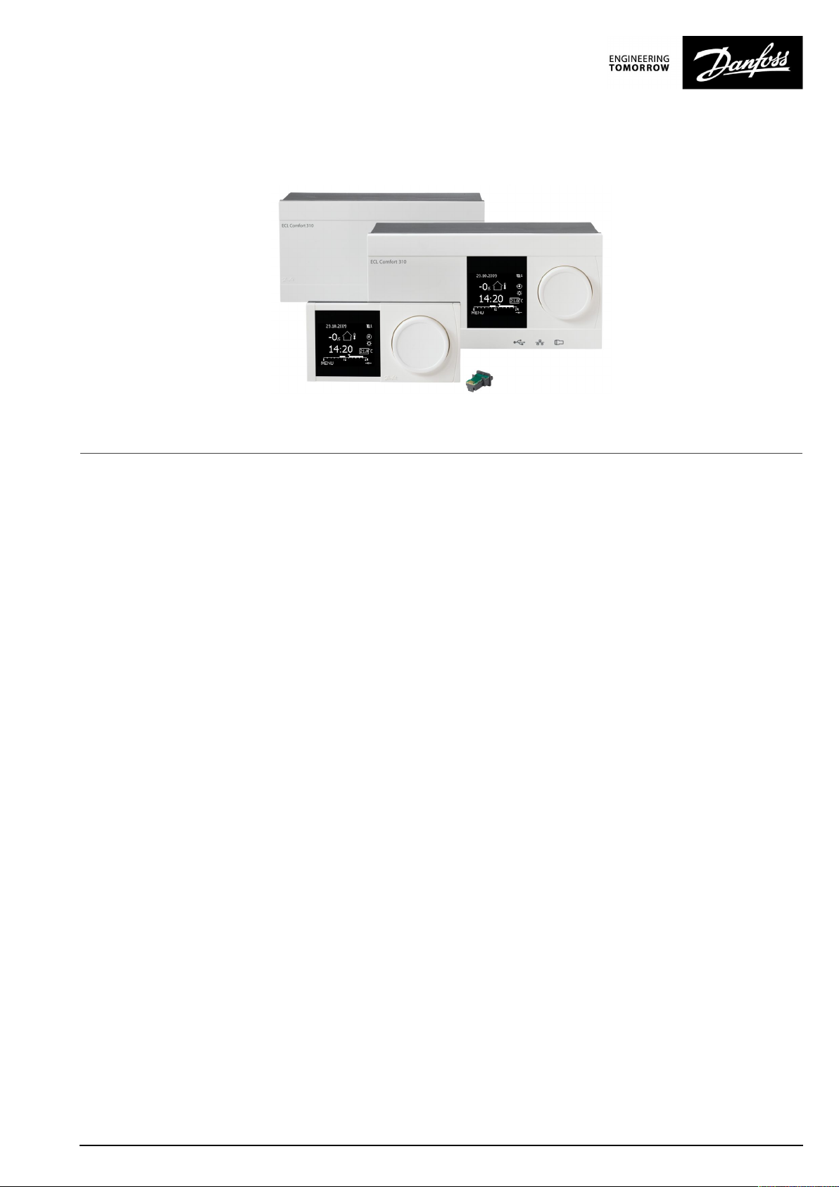
ECLComfort310isavailableas:
•ECLComfort310,230volta.c.(087H3040)
•ECLComfort310B,230volta.c.(087H3050)
•ECLComfort310,24volta.c.(087H3044)
2|©Danfoss|2021.06
AQ128686479024en-010601
Page 3
OperatingGuideECLComfort310,applicationA390
TheB-typehasnodisplayanddial.TheB-typeisoperatedby
meansoftheremotecontrolunitECA30/31:
•ECA30(087H3200)
•ECA31(087H3201)
InternalI/Omodule:
•ECA32(087H3202)
ThebasepartforECLComfort310,230voltand24volt:
•087H3230
AdditionaldocumentationforECLComfort310,modulesand
accessoriesisavailableonhttp://danfoss.com/.
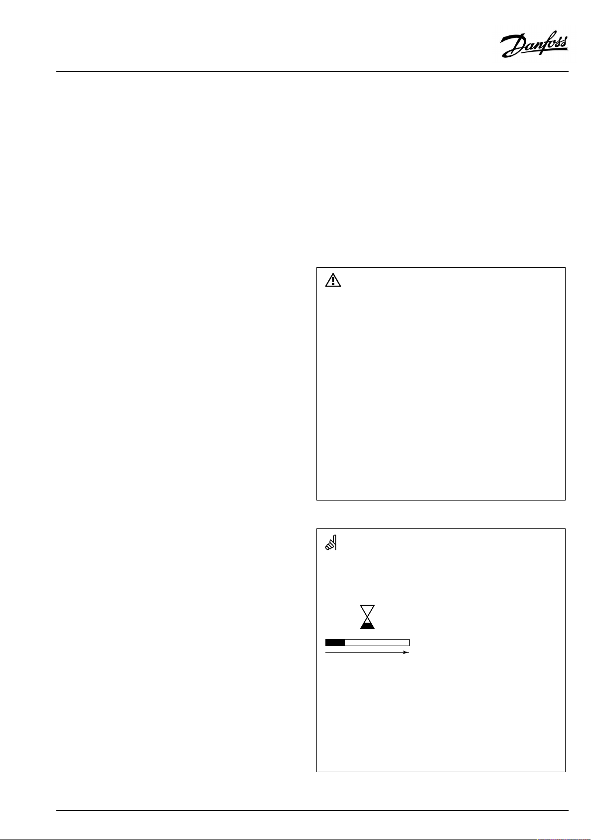
SafetyNote
Toavoidinjuryofpersonsanddamagestothedevice,itisabsolutely
necessarytoreadandobservetheseinstructionscarefully.
Necessaryassembly,start-up,andmaintenanceworkmustbe
performedbyqualifiedandauthorizedpersonnelonly.
Locallegislationsmustberespected.Thiscomprisesalsocable
dimensionsandtypeofisolation(doubleisolatedat230V).
AfusefortheECLComfortinstallationismax.10Atypically.
TheambienttemperaturerangesforECLComfortinoperationare:
ECLComfort210/310:0-55°C
ECLComfort296:0-45°C.
Exceedingthetemperaturerangecanresultinmalfunctions.
Installationmustbeavoidedifthereisariskforcondensation(dew).
Thewarningsignisusedtoemphasizespecialconditionsthatshould
betakenintoconsideration.
Automaticupdateofcontrollersoftware(firmware):
Thesoftwareofthecontrollerisupdatedautomaticallywhenthekey
isinserted(asofcontrollerversion1.11(ECL210/310)andversion
1.58(ECL296)).Thefollowinganimationwillbeshownwhenthe
softwareisbeingupdated:
Progressbar
Duringupdate:
•DonotremovetheKEY
Ifthekeyisremovedbeforethehour-glassisshown,youhave
tostartafresh.
•Donotdisconnectthepower
Ifthepowerisinterruptedwhenthehour-glassisshown,the
controllerwillnotwork.
•Manualupdateofcontrollersoftware(firmware):
Seethesection"Automatic/manualupdateoffirmware"
AQ128686479024en-010601
©Danfoss|2021.06|3
Page 4
OperatingGuideECLComfort310,applicationA390
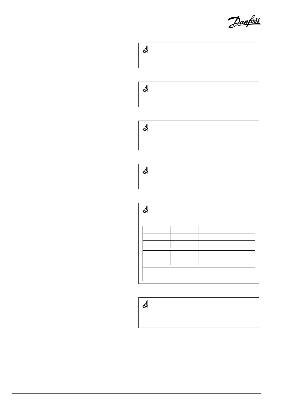
Thissymbolindicatesthatthisparticularpieceofinformationshould
bereadwithspecialattention.
Applicationkeysmightbereleasedbeforealldisplaytextsare
translated.InthiscasethetextisinEnglish.
AsthisOperatingGuidecoversseveralsystemtypes,specialsystem
settingswillbemarkedwithasystemtype.Allsystemtypesareshown
inthechapter:'Identifyingyoursystemtype'.
°C(degreesCelsius)isameasuredtemperaturevaluewhereasK
(Kelvin)oftenisusedfortemperaturedifferences.
TheIDno.isuniquefortheselectedparameter.
ExampleFirstdigitSeconddigitLastthreedigits
1117411174
-
12174
IfanIDdescriptionismentionedmorethanonce,itmeansthatthere
arespecialsettingsforoneormoresystemtypes.Itwillbemarked
withthesystemtypeinquestion(e.g.12174-A266.9).
ParametersindicatedwithanIDno.like"1x607"meanauniversal
parameter.
xstandsforcircuit/parametergroup.
1
-
Circuit1Parameterno.
2
Circuit2Parameterno.
174
4|©Danfoss|2021.06
AQ128686479024en-010601
Page 5
OperatingGuideECLComfort310,applicationA390
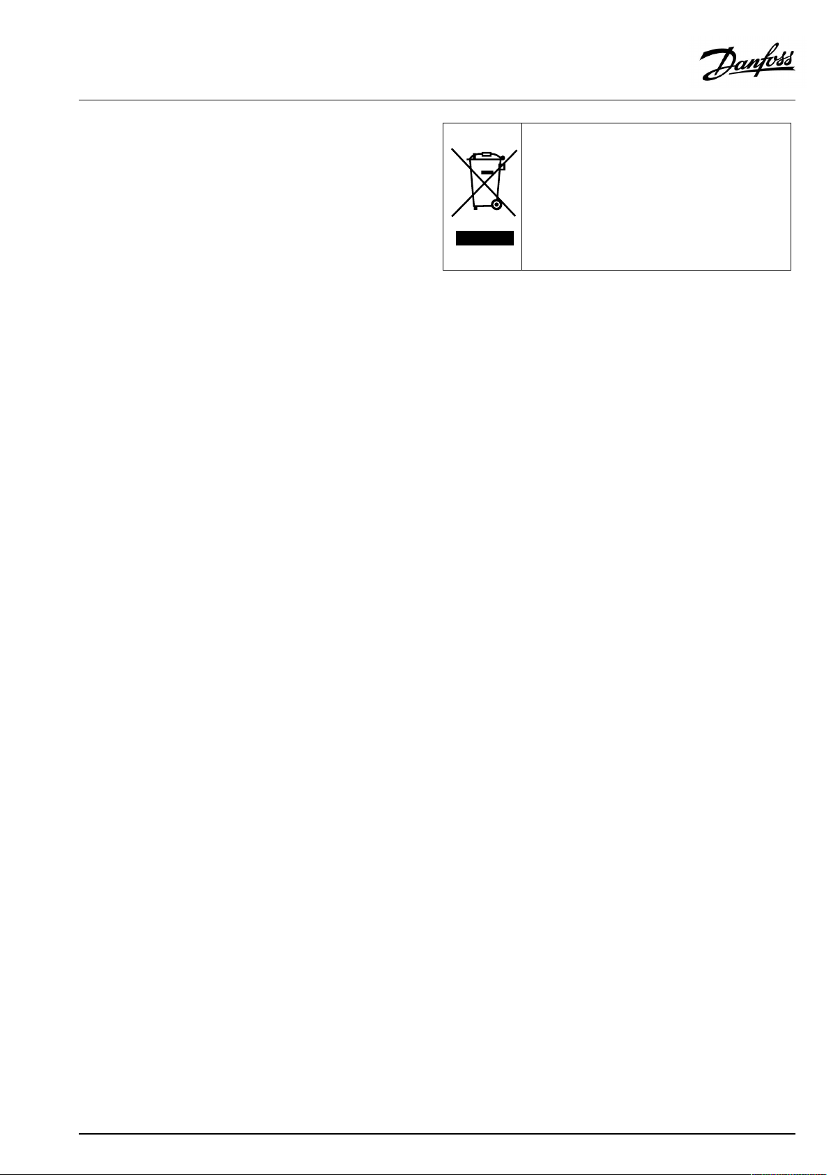
DisposalNote
Thissymbolontheproductindicatesthatitmaynot
bedisposedofashouseholdwaste.
Itmustbehandedovertotheapplicabletake-back
schemefortherecyclingofelectricalandelectronic
equipment.
•Disposeoftheproductthroughchannelsprovided
forthispurpose.
•Complywithalllocalandcurrentlyapplicablelaws
andregulations.
AQ128686479024en-010601
©Danfoss|2021.06|5
Page 6
OperatingGuideECLComfort310,applicationA390
2.0Installation
2.1Beforeyoustart
TheECLapplicationkeyA390contains6subtypes:A390.1,A390.2,
A390.3,A390.11,A390.12andA390.13.The6differentapplications
areheating,coolingandDHWapplicationsinvariouscombinations.
TheheatingbasedapplicationsA390.1,A390.2,A390.11,
A390.12andA390.13areveryflexible.
Thebasicprinciplesforaheatingcircuit
(examplereferringtoA390.1,circuit1)
Typically,theflowtemperatureisadjustedaccordingtoyour
requirements.Theflowtemperaturesensor(S3)isthemost
importantsensor.ThedesiredflowtemperatureatS3iscalculated
intheECLcontroller,basedontheoutdoortemperature(S1)and
thedesiredroomtemperature.Thelowertheoutdoortemperature,
thehigherthedesiredflowtemperature.
Bymeansofaweekschedule,theheatingcircuitcanbein‘Comfort’
or‘Saving’mode(twovaluesforthedesiredroomtemperature).
InSavingmodetheheatingcanbereducedorswitchedofftotally.
Themotorizedcontrolvalve(M1)isopenedgraduallywhenthe
flowtemperatureislowerthanthedesiredflowtemperatureand
viceversa.
Thereturntemperature(S5)canbelimited,forexamplenottobe
toohigh.Ifso,thedesiredflowtemperatureatS3canbeadjusted
(typicallytoalowervalue),thusresultinginagradualclosingof
themotorizedcontrolvalve.Furthermore,thereturntemperature
limitationcanbedependentontheoutdoortemperature.
Typically,thelowertheoutdoortemperature,thehigherthe
acceptedreturntemperature.
Inboiler-basedheatingsupplythereturntemperatureshouldnot
betoolow(sameadjustmentprocedureasabove).
Ifthemeasuredroomtemperaturedoesnotequalthedesired
roomtemperature,thedesiredflowtemperaturecanbeadjusted.
Thecirculationpump,P1,isONatheatdemandoratfrost
protection.
TheheatingcanbeswitchedOFFwhentheoutdoortemperatureis
higherthanaselectablevalue.
AconnectedfloworenergymeterbasedonM-bussignalcan
limitthefloworenergytoasetmaximumvalue.Furthermorethe
limitationcanbeinrelationtotheoutdoortemperature.Typically,
thelowertheoutdoortemperature,thehighertheacceptedflow/
power.
Thefrostprotectionmodemaintainsaselectableflowtemperature,
forexample10°C.
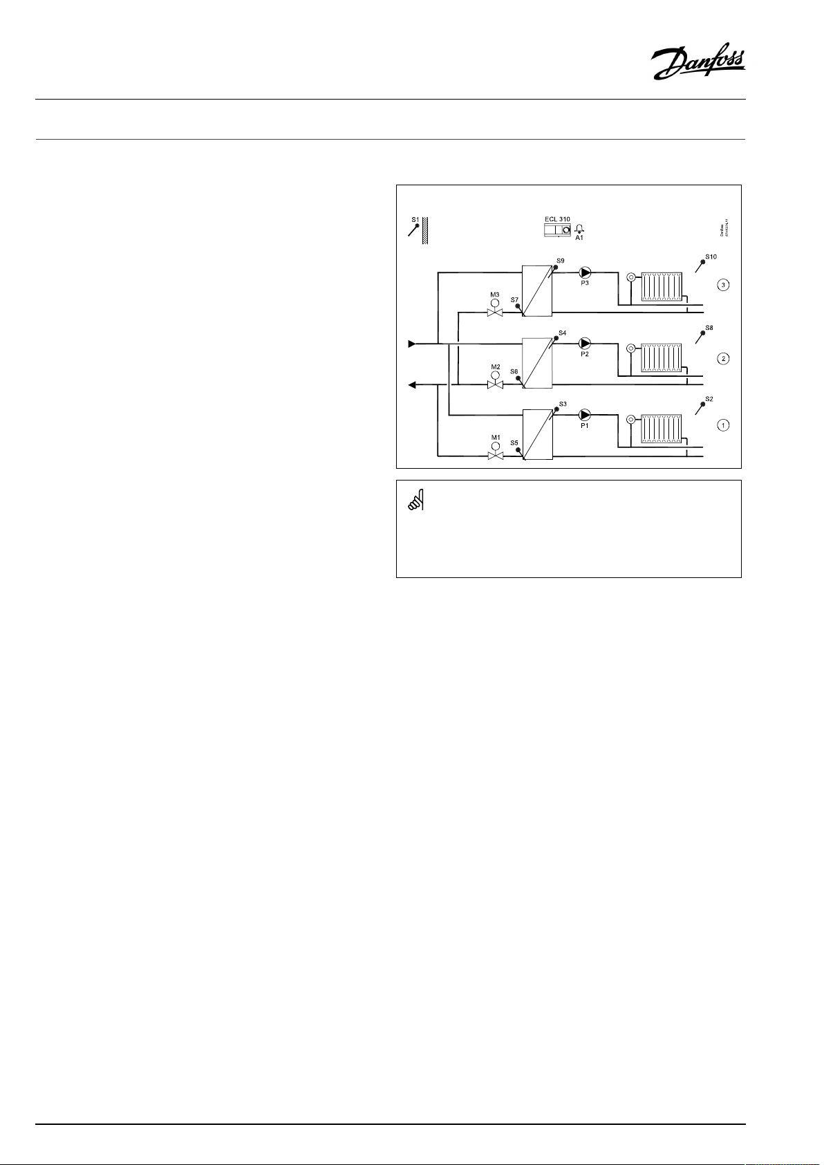
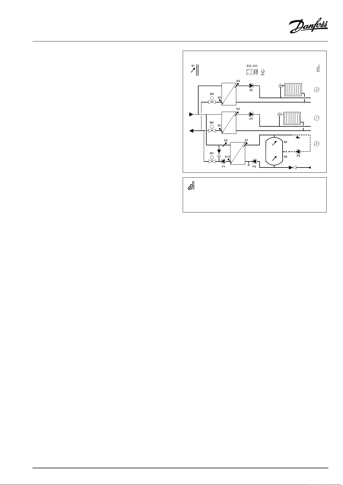
TypicalA390.1application:
Theshowndiagramisafundamentalandsimplifiedexampleanddoes
notcontainallcomponentsthatarenecessaryinasystem.
AllnamedcomponentsareconnectedtotheECLComfortcontroller.
Listofcomponents:
ECL310
S1
S2
S3
S4
S5
S6
S7
S8
S9
S10
P1
P2
P3
M1
M2
M3
A1
ElectroniccontrollerECLComfort310
Outdoortemperaturesensor
(Optional)Roomtemperaturesensor,circuit1
Flowtemperaturesensor,circuit1
Flowtemperaturesensor,circuit2
(Optional)Returntemperaturesensor,circuit1
(Optional)Returntemperaturesensor,circuit2
(Optional)Returntemperaturesensor,circuit3
(Optional)Roomtemperaturesensor,circuit2
Flowtemperaturesensor,circuit3
(Optional)Roomtemperaturesensor,circuit3
Circulationpump,heating,circuit1
Circulationpump,heating,circuit2
Circulationpump,heating,circuit3
Motorizedcontrolvalve(3-pointcontrolled),circuit1
Alternative:Thermoactuator(DanfosstypeABV)
Motorizedcontrolvalve(3-pointcontrolled),circuit2
Alternative:Thermoactuator(DanfosstypeABV)
Motorizedcontrolvalve(3-pointcontrolled),circuit3
Alternative:Thermoactuator(DanfosstypeABV)
Alarm
6|©Danfoss|2021.06
AQ128686479024en-010601
Page 7
OperatingGuideECLComfort310,applicationA390
A390.1,A390.2,A390.3,A390.11andA390.12:
Circuit1canactasmasterandtheremainingcircuitscanactas
slaves.
A390.2:
ThemotorizedcontrolvalvesM1,M2andM3arecontrolledby
meansof0-10voltsignals.Thecontrolsignalscomefromthe
internalI/OextensionmoduleECA32.The3-pointoutputsinthe
ECL310aredisabled.
A390.3,A390.11,A390.12,A390.13
ThemotorizedcontrolvalvesM1,M2andM3arecontrolledby
meansofeither3-pointor0-10voltsignals.Bothtypesofoutputs
areactive.The0–10VoltsignalscomefromtheinternalI/O
extensionmoduleECA32.
A390.11andA390.13:
Eachoftheheatingcircuitscanbesettoutilizetheroom
temperaturesensorS7.
Ifthereisademandfortwoseparateroomtemperaturesensors,
S7canbeusedforoneoftheheatingcircuitsandECA30forthe
otherheatingcircuit.
A390.11,A390.12andA390.13:
TheheatingcircuitscanbeclosedduringDHWheating(priority).
A390.13:
DHWheatinghaspriority.
A390.1,A390.2,A390.11,A390.12andA390.13:
AlarmA1(=relay6)canbeactivatedif:
•Theactualflowtemperaturediffersfromthedesiredflow
temperature.
•Ifatemperaturesensororitsconnectiondisconnects/short
circuits.(See:Commoncontrollersettings>System>Raw
inputoverview).
Heatingrelatedcircuits,ingeneral:
Exerciseofcirculationpumpsandcontrolvalvesinperiodswithout
heatingdemandcanbearranged.
ModbuscommunicationtoaSCADAsystemcanbeestablished.
AconnectedfloworenergymeterbasedonM-bussignalcan
limitthefloworpowertoasetmaximumvalue.Furthermore,the
limitationcanbeinrelationtotheoutdoortemperature.Typically,
thelowertheoutdoortemperature,thehighertheacceptedflow/
power.
M-busdatacanbetransferredtotheModbuscommunication.
A390,ingeneral:
UptotwoRemoteControlUnits,ECA30/31canbeconnectedto
oneECLcontrollerinordertocontroltheECLcontrollerremotely.
AdditionalECLComfortcontrollerscanbeconnectedviatheECL
485businordertoutilizecommonoutdoortemperaturesignal,
timeanddatesignals.
TheECLcontrollersintheECL485systemcanworkinmasterslavesystem.
Unusedinputscan,bymeansofanoverrideswitchorrelaycontact,
beusedforoverridingthescheduletoafixed'Comfort' ,'Saving',
'Frostprotection'or'Constanttemperature'mode.
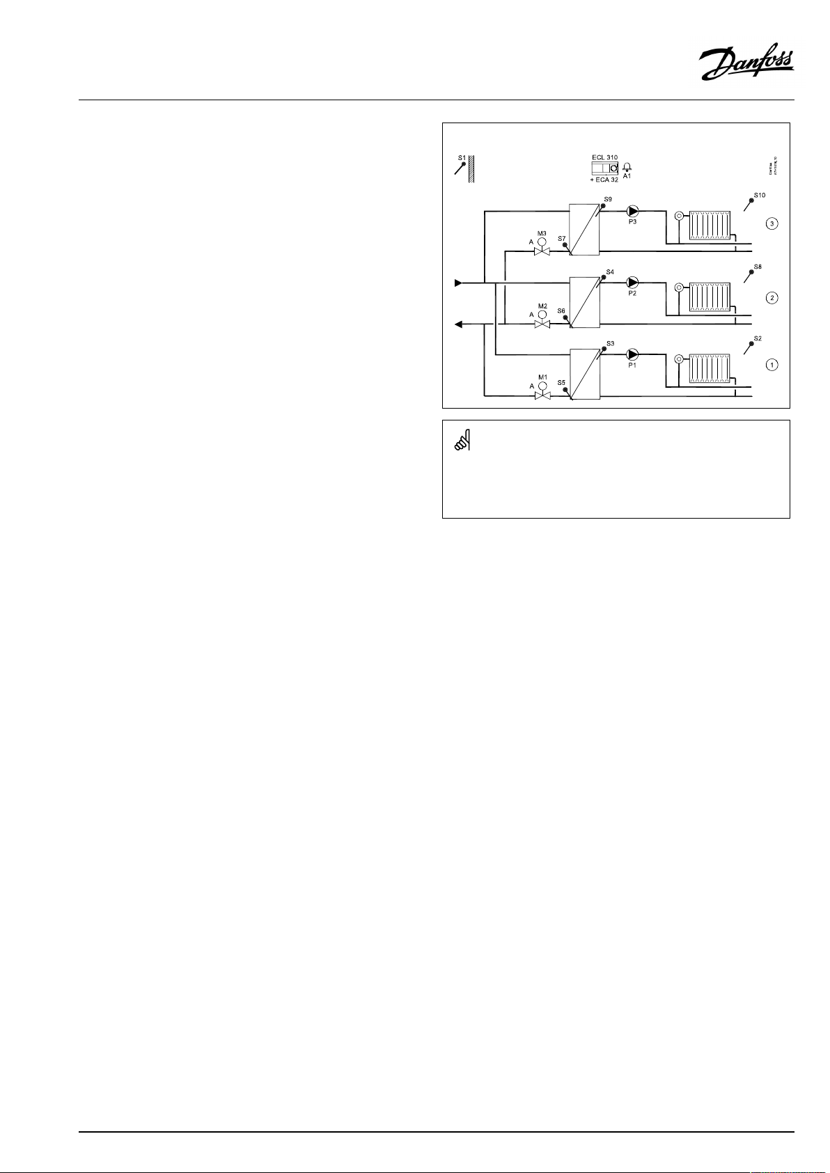
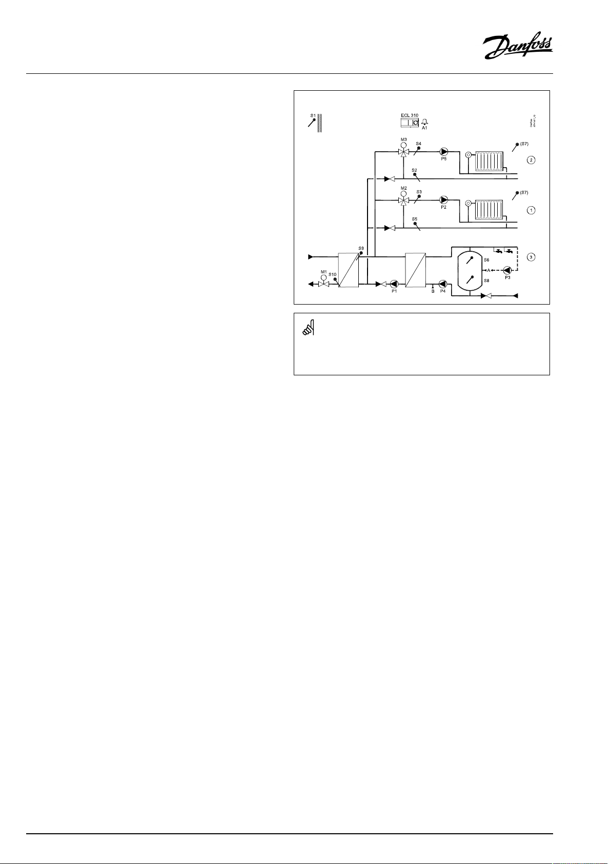
TypicalA390.2application:
Theshowndiagramisafundamentalandsimplifiedexampleanddoes
notcontainallcomponentsthatarenecessaryinasystem.
AllnamedcomponentsareconnectedtotheECLComfortcontroller.
Listofcomponents:
ECL310
ECA32
S1
S2
S3
S4
S5
ElectroniccontrollerECLComfort310
Built-inextensionmodule
Outdoortemperaturesensor
(Optional)Roomtemperaturesensor,circuit1
Flowtemperaturesensor,circuit1
Flowtemperaturesensor,circuit2
(Optional)Returntemperaturesensor,
circuit1
S6
(Optional)Returntemperaturesensor,
circuit2
S7
(Optional)Returntemperaturesensor,
circuit3
S8
S9
S10
P1
P2
P3
M1
(Optional)Roomtemperaturesensor,circuit2
Flowtemperaturesensor,circuit3
(Optional)Roomtemperaturesensor,circuit3
Circulationpump,circuit1
Circulationpump,circuit2
Circulationpump,circuit3
Motorizedcontrolvalve(0-10voltcontrolled),
circuit1
M2
Motorizedcontrolvalve(0-10voltcontrolled),
circuit2
M3
Motorizedcontrolvalve(0-10voltcontrolled),
circuit3
AQ128686479024en-010601
©Danfoss|2021.06|7
Page 8
OperatingGuideECLComfort310,applicationA390
ThecoolingapplicationA390.3isveryflexible.
Thebasicprinciplesforacoolingcircuit
(examplereferringtoA390.3,circuit1)
Typically,theflowtemperatureisadjustedaccordingtoyour
requirements.TheflowtemperaturesensorS3isthemost
importantsensor.ThedesiredflowtemperatureatS3issetin
theECLcontroller.Furthermore,theoutdoortemperatureS1can
influencethedesiredflowtemperature.Thehighertheoutdoor
temperature,thelowerthedesiredflowtemperature.
Bymeansoftheweekschedule,thecoolingcircuitcanbein
‘Comfort’or‘Saving’mode(twovaluesforthedesiredflow
temperature).
Theweekschedulealsocontrolstwovalues(‘Comfort’and
‘Saving’)forthedesiredroomtemperature.Ifthemeasuredroom
temperaturedoesnotequalthedesiredroomtemperature,the
desiredflowtemperaturecanbeadjusted.
ThemotorizedcontrolvalveM1isopenedgraduallywhenthe
flowtemperatureishigherthanthedesiredflowtemperatureand
viceversa.
ThereturntemperatureS5tothecoolingsupplyshouldnotbetoo
low.Ifso,thedesiredflowtemperaturecanbeadjusted(typicallyto
ahighervalue),thusresultinginagradualclosingofthemotorized
controlvalve.
ThecirculationpumpP1isONatcoolingdemand.
Aconnectedfloworenergymeter(M-bus)canlimittheflowor
energytoasetmaximumvalue.
Thestandbymodemaintainsaselectableflowtemperature,for
example30°C.
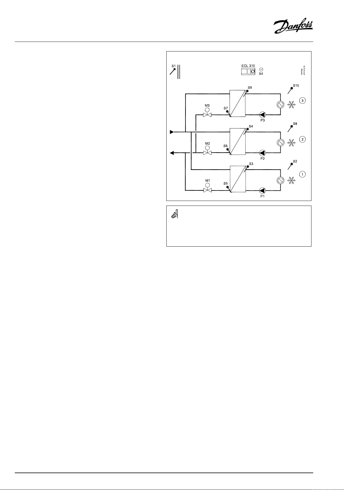
TypicalA390.3application:
Theshowndiagramisafundamentalandsimplifiedexampleanddoes
notcontainallcomponentsthatarenecessaryinasystem.
AllnamedcomponentsareconnectedtotheECLComfortcontroller.
Listofcomponents:
ECL310
ECA32
S1
S2
S3
S4
S5
S6
S7
S8
S9
S10
P1
P2
P3
M1
ElectroniccontrollerECLComfort310
(notillustrated)*)
Outdoortemperaturesensor
(Optional)Roomtemperaturesensor,circuit1
Flowtemperaturesensor,circuit1
Flowtemperaturesensor,circuit2
(Optional)Returntemperaturesensor,circuit1
(Optional)Returntemperaturesensor,circuit2
(Optional)Returntemperaturesensor,circuit3
(Optional)Roomtemperaturesensor,circuit2
Flowtemperaturesensor,circuit3
(Optional)Roomtemperaturesensor,circuit3
Circulationpump,circuit1
Circulationpump,circuit2
Circulationpump,circuit3
Motorizedcontrolvalve(3-pointand/or0-10Volt
controlled),circuit1
Alternative:Thermoactuator(DanfosstypeABV)
M2
Motorizedcontrolvalve(3-pointand/or0-10Volt
controlled),circuit2
Alternative:Thermoactuator(DanfosstypeABV)
M3
Motorizedcontrolvalve(3-pointand/or0-10Volt
controlled),circuit3
Alternative:Thermoactuator(DanfosstypeABV)
X4
*)
Extraoutput(Schedule4)
Usedfor0-10Voltcontrolofmotorizedcontrolvalve.
8|©Danfoss|2021.06
AQ128686479024en-010601
Page 9
OperatingGuideECLComfort310,applicationA390
ThebasicprinciplesforaDomesticHotWatercircuit(DHW)
(examplereferringtoA390.11,circuit4)
Bymeansofaweekschedule(upto3'Comfort'periods/day),the
DHWcircuitcanbein'Comfort'or'Saving'mode(twodifferent
temperaturevaluesforthedesiredDHWtemperatureatS6).
TheDHWheatingtemperaturesensorS3isthemostimportant
sensor.IfthemeasuredDHWtemperature(S6)getslowerthanthe
desiredDHWtemperature,theDHWheatingpump(P4)isswitched
ONandtheheatingcirculationpumpP1isswitchedOFF.
ThemotorizedcontrolvalveM1iscontrolledinordertomaintain
theDHWheatingtemperatureatS3.
TheDHWheatingtemperatureisdeterminedbythedesiredDHW
temperatureatS6plusthechargingdifference.
TheDHWchargingpumpP7canbeswitchedONdependingon1)
theDHWheatingtemperatureisreached,or2)adelay.
TheDHWheatingtemperatureatS3istypically5–10degrees
higherthanthedesiredDHWtemperature.
DHWtankwith1temperaturesensor(S6):
WhenthemeasuredDHWtemperature(S6)getshigherthanthe
desiredDHWtemperature,theDHWheatingpump(P4)andthe
DHWchargingpump(P7)areswitchedOFF.Thepost-runtimecan
besetindividually.
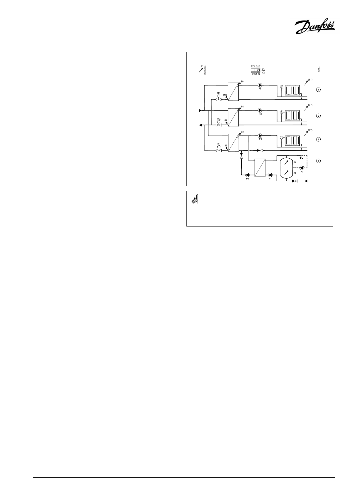
TypicalA390.11application:(upto3xheating,1xDHW)
Theshowndiagramisafundamentalandsimplifiedexampleanddoes
notcontainallcomponentsthatarenecessaryinasystem.
AllnamedcomponentsareconnectedtotheECLComfortcontroller.
DHWtankwith2temperaturesensors(S6,upperandS8,
lower):
WhenthemeasuredDHWtemperature(S6)getshigherthanthe
desiredDHWtemperatureandthetemperatureatS8getshigher
thanthecut-outtemperature,theDHWheatingpump(P4)and
theDHWchargingpump(P7)areswitchedOFF.Thepost-runtime
canbesetindividually.
Thereturntemperature(S5)canbelimited,forexamplenottobe
toohigh.Ifso,thedesiredflowtemperatureatS3canbeadjusted
(typicallytoalowervalue),thusresultinginagradualclosingofthe
motorizedcontrolvalve.
Aflow/powerlimitationcanbearrangedbyusinganM-busbased
signalfromaflow/heatmeter.
A390.12:
TheDHWheatingcircuithasapreheatingcircuit,wheretheDHW
heatingtemperatureatS9isadaptedtothedesiredDHWcharging
temperatureatS7.IftheDHWchargingtemperatureatS7cannot
bereached,theECLcontrollergraduallyincreasesthedesiredDHW
heatingtemperatureatS9inordertoobtaintheDHWcharging
temperature.Amaximumtemperaturevaluecanbeset.
A390.12:
TheDHWcirculationcanbethroughtheDHWtank(connectionA)
orthroughtheheat-exchanger(connectionB).Thesolutionwith
connectionAresultsinclosingofthemotorizedcontrolvalveafter
theDHWtankchargingprocedure.Thesolutionwithconnection
BisusedtocompensatefortheheatlossintheDHWcirculation
pipe.Furthermore,afterDHWtankcharging,theDHWheating
temperature(atS7)iscontrolledaccordingtothedesiredDHW
temperature.
Listofcomponents:
ECL310
ECA32
S1
S2
S3
S4
S5
S6
S7
S8
ElectroniccontrollerECLComfort310
Built-inextensionmodule*)
Outdoortemperaturesensor
(Optional)Returntemperaturesensor,circuit2
Flowtemperaturesensor,circuit1
Flowtemperaturesensor,circuit2
(Optional)Returntemperaturesensor,circuit1
DHWtanktemperaturesensor,upper,circuit4
(Optional)Roomtemperaturesensor,circuit1/2/3
(Optional)DHWtanktemperaturesensor,lower,
circuit4
S9
S10
P1
P2
P3
P4
P5
P7
M1
Flowtemperaturesensor,circuit3
(Optional)Returntemperaturesensor,circuit3
Circulationpump,circuit1
Circulationpump,circuit2
DHWcirculationpump,circuit4
DHWheatingpump,circuit4
Circulationpump,circuit3
DHWchargingpump,circuit4
Motorizedcontrolvalve(3-pointand/or0-10Volt
controlled),circuit1
Alternative:Thermoactuator(DanfosstypeABV)
M2
Motorizedcontrolvalve(3-pointand/or0-10Volt
controlled),circuit2
Alternative:Thermoactuator(DanfosstypeABV)
M3
Motorizedcontrolvalve(3-pointand/or0-10Volt
controlled),circuit3
Alternative:Thermoactuator(DanfosstypeABV)
A1
*)
Alarm
Alsousedfor0-10Voltcontrolofmotorizedcontrol
valve.
AQ128686479024en-010601
©Danfoss|2021.06|9
Page 10

OperatingGuideECLComfort310,applicationA390
A390.13:
TheDHWheatinghaspriorityovertheheatingcircuits.
TheDHWcircuitisconsideredasthemastercircuitwhilethe
heatingcircuitsareslaves.
TemperaturesensorS9isthemostimportantsensor.
TheDHWcirculationcanbethroughtheDHWtank(connectionA)
orthroughtheheat-exchanger(connectionB).
Generalinformation:
The‘Frostprotection’modemaintainsaselectabletemperature,
forexample10°C.
Ananti-bacteriafunctionisavailableforactivationonselected
daysoftheweek.
Theoutdoortemperature(S1)isusedtoprotectthecirculation
circuitagainstfrost.
TheDHWcirculationpump(P3)hasaweekscheduleforupto3
ONperiodsperday.
Ameasuredtemperaturecanbeoffsetadjusted,ifneeded.
WhenanA390subtypehasbeenuploaded,theECLComfort
controllerstartsinmanualmode.Thiscanbeusedforcheckingthe
controlledcomponentsforcorrectfunctionality.
Theapplicationkeymustbeinsertedinordertochangesettings.
10|©Danfoss|2021.06
AQ128686479024en-010601
Page 11
OperatingGuideECLComfort310,applicationA390
TypicalA390.12application:
(upto2xheating,1xDHW)
TypicalA390.12application:(upto2xheating,1xDHW)
Theshowndiagramisafundamentalandsimplifiedexampleanddoes
notcontainallcomponentsthatarenecessaryinasystem.
AllnamedcomponentsareconnectedtotheECLComfortcontroller.
Listofcomponents:
ECL310
ECA32
S1
S2
S3
S4
S5
S6
S7
S8
ElectroniccontrollerECLComfort310
(notillustrated)*)
Outdoortemperaturesensor
(Optional)Returntemperaturesensor,circuit2
Flowtemperaturesensor,circuit1
Flowtemperaturesensor,circuit2
(Optional)Returntemperaturesensor,circuit1
DHWtanktemperaturesensor,upper,circuit3
DHWchargingtemperaturesensor,circuit3
(Optional)DHWtanktemperaturesensor,lower,
circuit3
S9
S10
P1
P2
P3
P4
P5
M1
DHWheatingtemperaturesensor,circuit3
(Optional)Returntemperaturesensor,circuit3
DHWheatingpump,circuit3
Circulationpump,circuit1
DHWcirculationpump,circuit3
DHWchargingpump,circuit3
Circulationpump,circuit2
Motorizedcontrolvalve(3-pointand/or0-10Volt
controlled),circuit3
M2
Motorizedcontrolvalve(3-pointand/or0-10Volt
controlled),circuit1
Alternative:Thermoactuator(DanfosstypeABV)
M3
Motorizedcontrolvalve(3-pointand/or0-10Volt
controlled),circuit2
Alternative:Thermoactuator(DanfosstypeABV)
A1
A/B
*)
Alarm
Internal/externalconnectionsforDHWcirculation
Usedfor0-10Voltcontrolofmotorizedcontrolvalve.
AQ128686479024en-010601
©Danfoss|2021.06|11
Page 12
OperatingGuideECLComfort310,applicationA390
TypicalA390.13application:
(1xDHW,upto2xheating)
TypicalA390.13application:(1xDHW,upto2xheating)
Theshowndiagramisafundamentalandsimplifiedexampleanddoes
notcontainallcomponentsthatarenecessaryinasystem.
AllnamedcomponentsareconnectedtotheECLComfortcontroller.
Listofcomponents:
ECL310
ECA32
S1
S2
S3
S4
S5
S6
S7
S8
ElectroniccontrollerECLComfort310
(notillustrated)*)
Outdoortemperaturesensor
(Optional)Returntemperaturesensor,circuit2
Flowtemperaturesensor,circuit1
Flowtemperaturesensor,circuit2
(Optional)Returntemperaturesensor,circuit1
DHWtanktemperaturesensor,upper,circuit3
(Optional)Roomtemperaturesensor,circuit1/2
(Optional)DHWtanktemperaturesensor,lower,
circuit3
S9
S10
P1
P2
P3
P4
P5
M1
DHWheatingtemperaturesensor,circuit3
(Optional)Returntemperaturesensor,circuit3
DHWheatingpump,circuit3
Circulationpump,circuit1
DHWcirculationpump,circuit3
DHWchargingpump,circuit3
Circulationpump,circuit2
Motorizedcontrolvalve(3-pointand/or0-10Volt
controlled),circuit3
M2
Motorizedcontrolvalve(3-pointand/or0-10Volt
controlled),circuit1
Alternative:Thermoactuator(DanfosstypeABV)
M3
Motorizedcontrolvalve(3-pointand/or0-10Volt
controlled),circuit2
Alternative:Thermoactuator(DanfosstypeABV)
A1
A/B
*)
Alarm
Internal/externalconnectionsforDHWcirculation
Usedfor0-10Voltcontrolofmotorizedcontrolvalve.
12|©Danfoss|2021.06
AQ128686479024en-010601
Page 13

OperatingGuideECLComfort310,applicationA390
Thecontrollerispre-programmedwithfactorysettingsthatareshown
inthe‘ParameterIDoverview’appendix.
AQ128686479024en-010601
©Danfoss|2021.06|13
Page 14
OperatingGuideECLComfort310,applicationA390
2.2Identifyingthesystemtype
Sketchyourapplication
TheECLComfortcontrollerseriesisdesignedforawiderange
ofheating,domestichot-water(DHW)andcoolingsystemswith
differentconfigurationsandcapacities.Ifyoursystemdiffers
fromthediagramsshownhere,youmaywanttomakeasketch
ofthesystemabouttobeinstalled.Thismakesiteasiertouse
theOperatingGuide,whichwillguideyoustep-by-stepfrom
installationtofinaladjustmentsbeforetheend-usertakesover.
TheECLComfortcontrollerisauniversalcontrollerthatcanbe
usedforvarioussystems.Basedontheshownstandardsystems,
itispossibletoconfigureadditionalsystems.Inthischapteryou
findthemostfrequentlyusedsystems.Ifyoursystemisnotquite
asshownbelow,findthediagramwhichhasthebestresemblance
withyoursystemandmakeyourowncombinations.
SeetheInstallationGuide(deliveredwiththeapplicationkey)for
applicationtypes/sub-types.
Thecirculationpump(s)inheatingcircuit(s)canbeplacedintheflow
aswellasthereturn.Placethepumpaccordingtothemanufacturer’s
specification.
14|©Danfoss|2021.06
AQ128686479024en-010601
Page 15
OperatingGuideECLComfort310,applicationA390
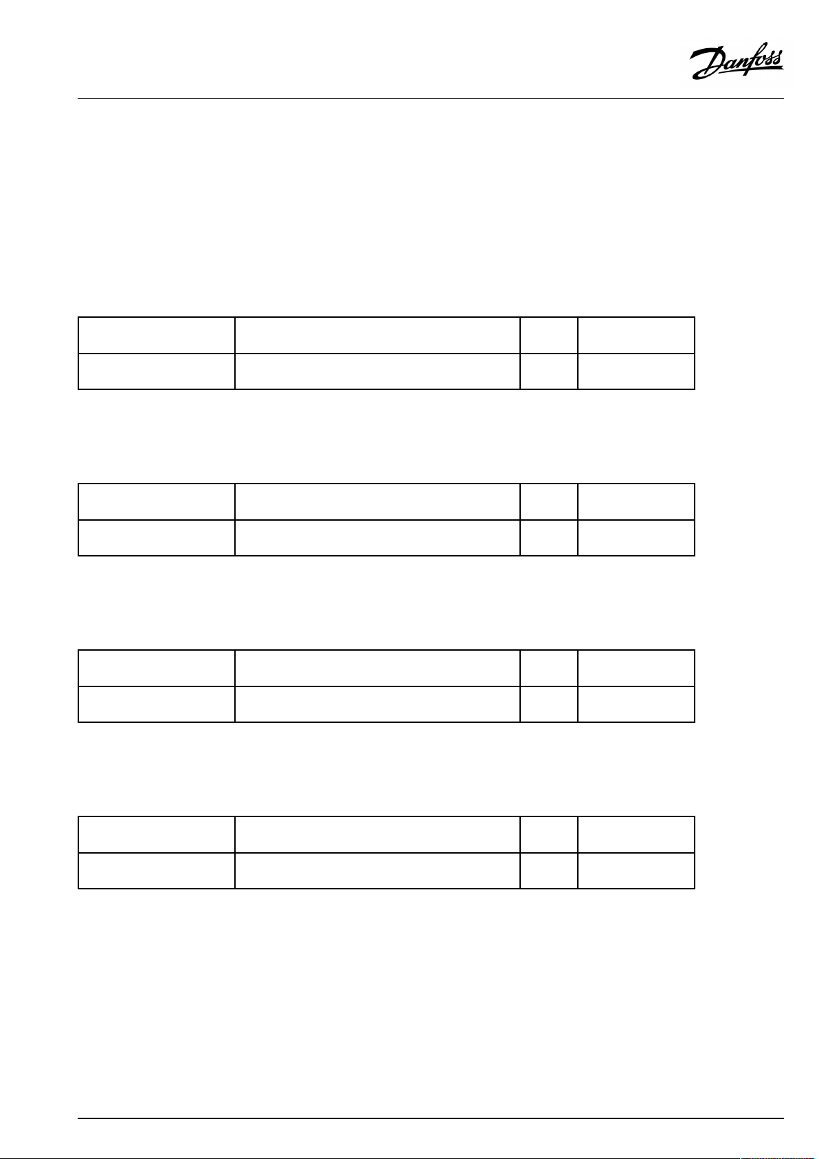
Adviceforsettings:
Factorysettingsinthesubtypeswillrunthemostapplication
examples.Someoftheapplicationexamplesneedchangeof
dedicatedsettings.
SeetheInstallationGuideforapplicationsandsubtypes,delivered
withtheapplicationkey.
A390.1,ex.c
A390.11,ex.d
Circuit1mustbeabletoreceivetheheatdemandfromcircuit2
and/or3.
Issue:
Heatingcircuit(1):
Heatdemand
*Thisvalueisaddedtotheheatdemandvaluefromcircuit2and/
or3.
Circuit2and/or3mustbeabletosendtheheatdemandtocircuit
1.
Issue:
Heatingcircuit(2/3):
Heatdemand
A390.3,ex.b
Circuit1mustbeabletoreceivethecooldemandfromcircuit2
and/or3.
Issue:
Coolingcircuit(1):
Cooldemand
Navigation:
MENU\Settings\Application:
'Demandoffset'
Navigation:
MENU\Settings\Application:
'SenddesiredT'
Navigation:
MENU\Settings\Application:
'Demandoffset'
IDno.:
11017
IDno.:
12500
13500
IDno.:
11017
Recommended
setting:
3K*
Recommended
setting:
ON
ON
Recommended
setting:
-3K*
Thisvalueisaddedtothecooldemandvaluefromcircuit2and/
or3.
Circuit2and/or3mustbeabletosendthecooldemandtocircuit
1.
Issue:
Coolingcircuit(2/3):
Cooldemand
AQ128686479024en-010601
Navigation:
MENU\Settings\Application:
'SenddesiredT'
IDno.:
12500
13500
Recommended
setting:
ON
ON
©Danfoss|2021.06|15
Page 16
OperatingGuideECLComfort310,applicationA390
Adviceforsettings:
A390.11,ex.c
Onepumpandchange-overvalvesystem:
Issue:
DHWcircuit(4):
Change-overvalve
A390.11,ex.e
DHWheatingconnectedprimarily:
Issue:
DHWcircuit(4):
Change-overvalve
DHWcircuit(4):
Tankprimarily
A390.12,ex.a
A390.12,ex.b
A390.13,ex.a
DHWcirculationpipecanbeconnectedtotheDHWtankat'A'
forinternalcirculationortotheheat-exchangerat'B'forexternal
circulation.
Issue:
DHWcircuit(3):
InternalDHWcirculation
DHWcircuit(3):
ExternalDHWcirculation
Navigation:
MENU\Settings\Application:
'Ch.-o.valve/P'
Navigation:
MENU\Settings\Application:
'Ch.-o.valve/P'
MENU\Settings\Application:
'Tank,sec./prim'
Navigation:
MENU\Settings\Application:
'Cont.Tcontrol'
MENU\Settings\Application:
'Cont.Tcontrol'
IDno.:
14051
IDno.:
14051
14053
IDno.:
13054
13054
Recommended
setting:
OFF
Recommended
setting:
OFF
ON
Recommended
setting:
OFF
ON
A390.12,ex.b
Circuit1mustbeabletoreceivetheheatdemandfromcircuit2.
Issue:
Heatingcircuit(1):
Heatdemand
*Thisvalueisaddedtotheheatdemandvaluefromcircuit2.
Circuit2mustbeabletosendtheheatdemandtocircuit1.
Issue:
Heatingcircuit(2):
Heatdemand
16|©Danfoss|2021.06
Navigation:
MENU\Settings\Application:
'Demandoffset'
Navigation:
MENU\Settings\Application:
'SenddesiredT'
IDno.:
11017
IDno.:
12500
Recommended
setting:
3K*
Recommended
setting:
ON
AQ128686479024en-010601
Page 17
OperatingGuideECLComfort310,applicationA390
2.3Mounting
2.3.1MountingtheECLComfortcontroller
Foreasyaccess,youshouldmounttheECLComfortcontrollernear
thesystem.Selectoneofthefollowingmethodsusingthesame
basepart(codeno.087H3230):
•Mountingonawall
•MountingonaDINrail(35mm)
TheECLComfort310canonlybemountedintheECLComfort
310basepart.
Screws,PGcableglandsandrawlplugsarenotsupplied.
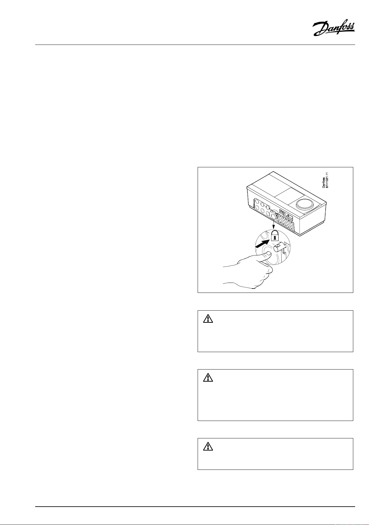
LockingtheECLComfort210/310controller
InordertofastentheECLComfortcontrollertoitsbasepart,secure
thecontrollerwiththelockingpin.
Topreventinjuriestopersonsorthecontroller,thecontrollerhasto
besecurelylockedintothebase.Forthispurpose,pressthelocking
pinintothebaseuntilaclickisheardandthecontrollernolonger
canberemovedfromthebase.
Ifthecontrollerisnotsecurelylockedintothebasepart,thereisarisk
thatthecontrollerduringoperationcanunlockfromthebaseandthe
basewithterminals(andalsothe230Va.c.connections)areexposed.
Topreventinjuriestopersons,alwaysmakesurethatthecontroller
issecurelylockedintoitsbase.Ifthisisnotthecase,thecontroller
shouldnotbeoperated!
Theeasywaytolockthecontrollertoitsbaseorunlockitistousea
screwdriveraslever.
AQ128686479024en-010601
©Danfoss|2021.06|17
Page 18
OperatingGuideECLComfort310,applicationA390
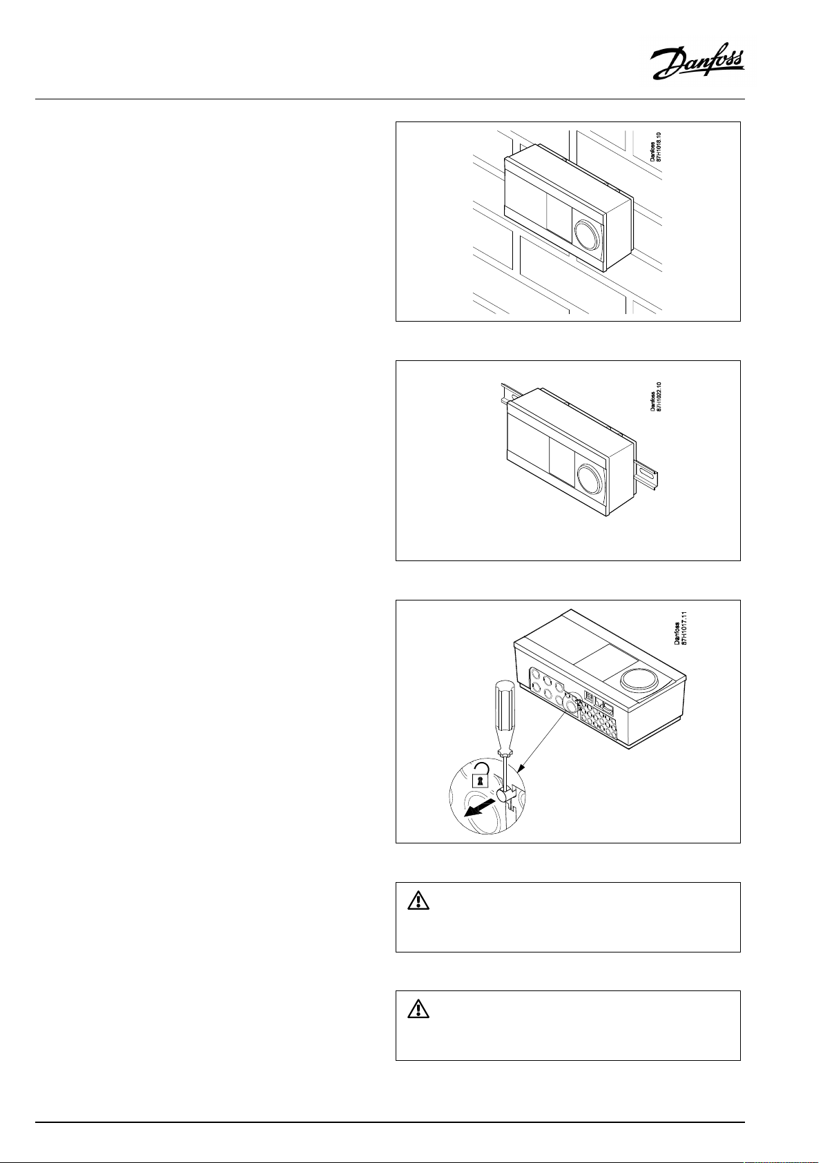
Mountingonawall
Mountthebasepartonawallwithasmoothsurface.Establishthe
electricalconnectionsandpositionthecontrollerinthebasepart.
Securethecontrollerwiththelockingpin.
MountingonaDINrail(35mm)
MountthebasepartonaDINrail.Establishtheelectrical
connectionsandpositionthecontrollerinthebasepart.Secure
thecontrollerwiththelockingpin.
DismountingtheECLComfortcontroller
Inordertoremovethecontrollerfromthebasepart,pulloutthe
lockingpinbymeansofascrewdriver.Thecontrollercannowbe
removedfromthebasepart.
Theeasywaytolockthecontrollertoitsbaseorunlockitistousea
screwdriveraslever.
18|©Danfoss|2021.06
BeforeremovingtheECLComfortcontrollerfromthebasepart,ensure
thatthesupplyvoltageisdisconnected.
AQ128686479024en-010601
Page 19
OperatingGuideECLComfort310,applicationA390
2.3.2MountingtheRemoteControlUnitsECA30/31
Selectoneofthefollowingmethods:
•Mountingonawall,ECA30/31
•Mountinginapanel,ECA30
Screwsandrawlplugsarenotsupplied.
Mountingonawall
MountthebasepartoftheECA30/31onawallwithasmooth
surface.Establishtheelectricalconnections.PlacetheECA30/
31inthebasepart.
Mountinginapanel
MounttheECA30inapanelusingtheECA30framekit(ordercode
no.087H3236).Establishtheelectricalconnections.Securethe
framewiththeclamp.PlacetheECA30inthebasepart.TheECA
30canbeconnectedtoanexternalroomtemperaturesensor.
TheECA31mustnotbemountedinapanelifthehumidity
functionistobeused.
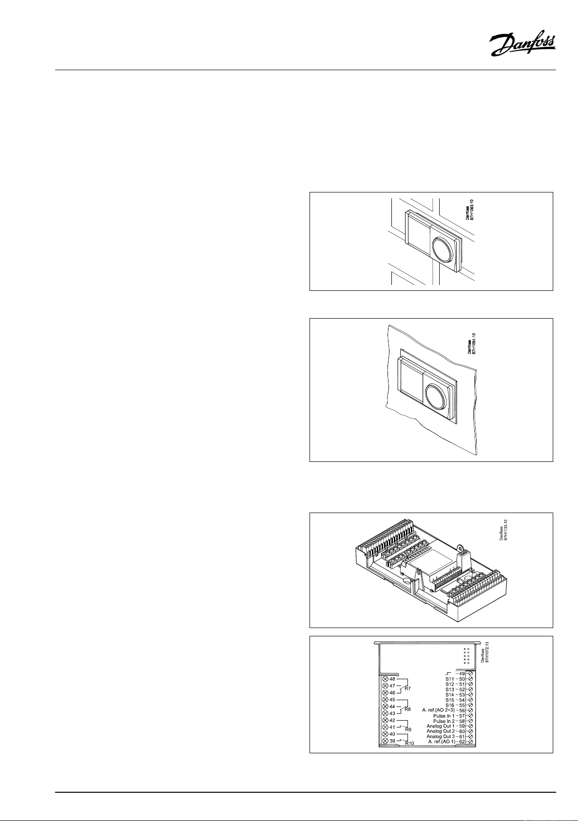
2.3.3MountingtheinternalI/OmoduleECA32
MountingoftheinternalI/OmoduleECA32
TheECA32module(ordercodeno.087H3202)mustbeinserted
intotheECLComfort310/310Bbasepartforadditionalinputand
outputsignalsinrelevantapplications.
TheconnectionbetweentheECLComfort310/310BandECA32
isa10-pole(2x5)connector.Theconnectionisautomatically
establishedwhentheECLComfort310/310Bisplacedonthe
basepart.
AQ128686479024en-010601
©Danfoss|2021.06|19
Page 20
OperatingGuideECLComfort310,applicationA390
2.4Placingthetemperaturesensors
Itisimportantthatthesensorsaremountedinthecorrectposition
inyoursystem.
Thetemperaturesensormentionedbelowaresensorsusedforthe
ECLComfort210/296/310serieswhichnotallwillbeneeded
foryourapplication!
Outdoortemperaturesensor(ESMT)
Theoutdoorsensorshouldbemountedonthatsideofthebuilding
whereitislesslikelytobeexposedtodirectsunshine.Itshouldnot
beplacedclosetodoors,windowsorairoutlets.
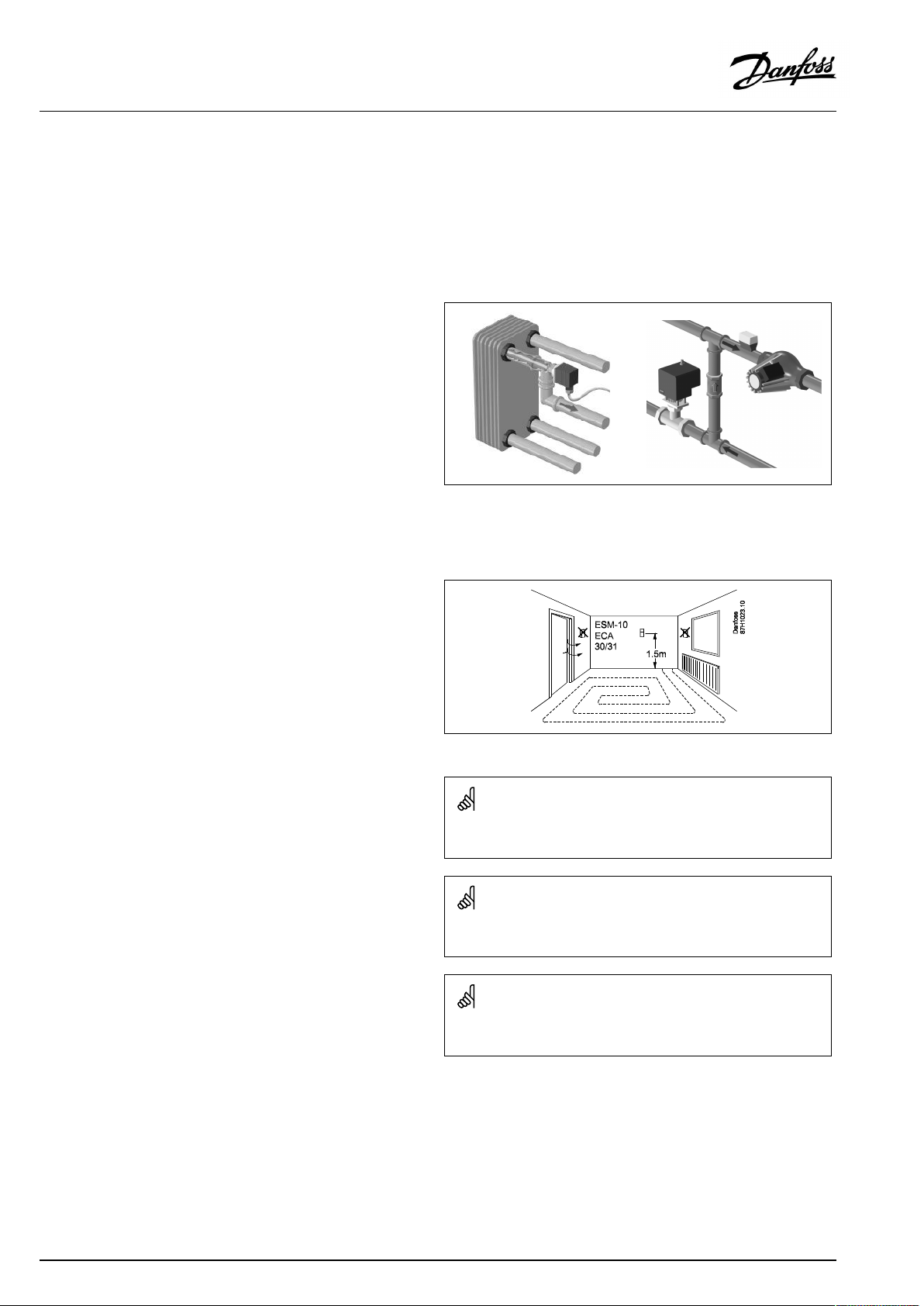
Flowtemperaturesensor(ESMU,ESM-11orESMC)
Placethesensormax.15cmfromthemixingpoint.Insystems
withheatexchanger,DanfossrecommendsthattheESMU-typeto
beinsertedintotheexchangerflowoutlet.
Makesurethatthesurfaceofthepipeiscleanandevenwhere
thesensorismounted.
Returntemperaturesensor(ESMU,ESM-11orESMC)
Thereturntemperaturesensorshouldalwaysbeplacedsothatit
measuresarepresentativereturntemperature.
Roomtemperaturesensor
(ESM-10,ECA30/31RemoteControlUnit)
Placetheroomsensorintheroomwherethetemperatureistobe
controlled.Donotplaceitonoutsidewallsorclosetoradiators,
windowsordoors.
Boilertemperaturesensor(ESMU,ESM-11orESMC)
Placethesensoraccordingtotheboilermanufacturer’s
specification.
Airducttemperaturesensor(ESMB-12orESMUtypes)
Placethesensorsothatitmeasuresarepresentativetemperature.
DHWtemperaturesensor(ESMUorESMB-12)
PlacetheDHWtemperaturesensoraccordingtothemanufacturer’s
specification.
Slabtemperaturesensor(ESMB-12)
Placethesensorinaprotectiontubeintheslab.
ESM-11:Donotmovethesensorafterithasbeenfastenedinorderto
avoiddamagetothesensorelement.
ESM-11,ESMCandESMB-12:Useheatconductingpasteforquick
measurementofthetemperature.
ESMUandESMB-12:Usingasensorpockettoprotectthesensorwill,
however,resultinaslowertemperaturemeasurement.
20|©Danfoss|2021.06
AQ128686479024en-010601
Page 21
OperatingGuideECLComfort310,applicationA390
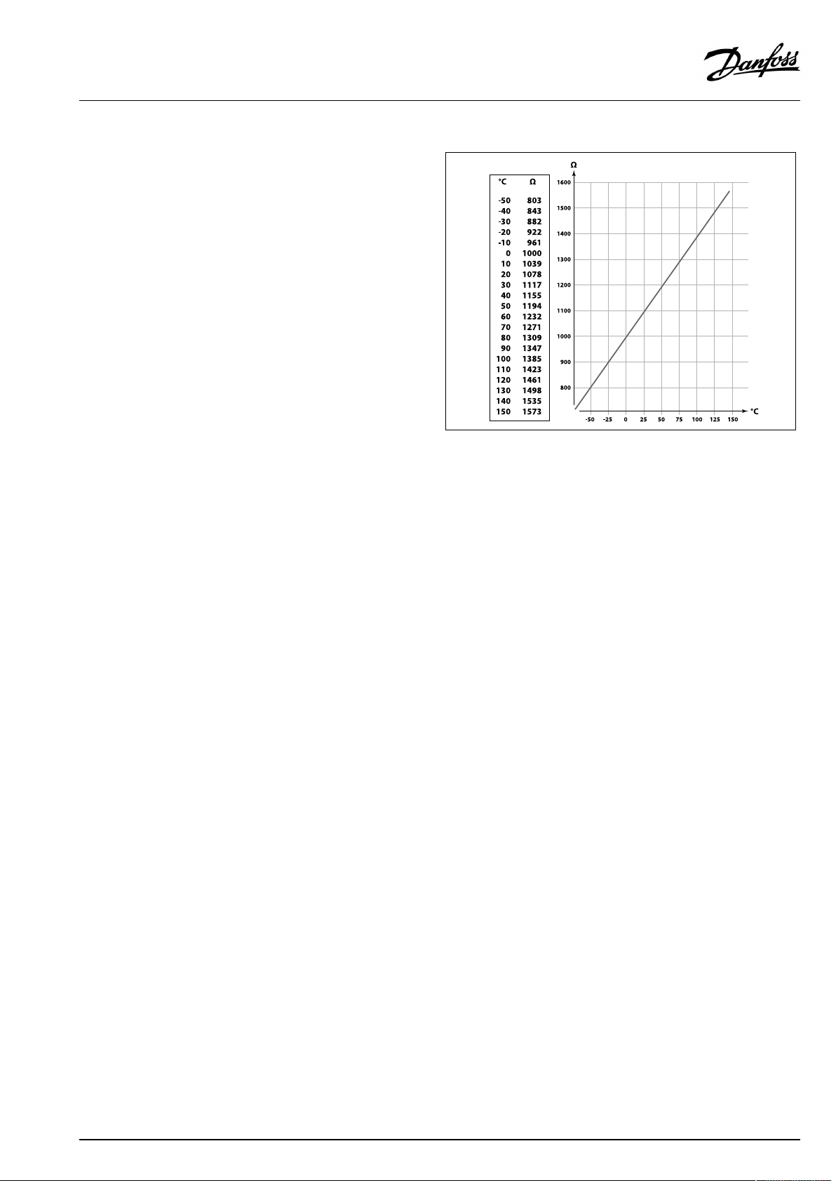
Pt1000temperaturesensor(IEC751B,1000Ω/0°C)
Relationshipbetweentemperatureandohmicvalue:
AQ128686479024en-010601
©Danfoss|2021.06|21
Page 22
OperatingGuideECLComfort310,applicationA390
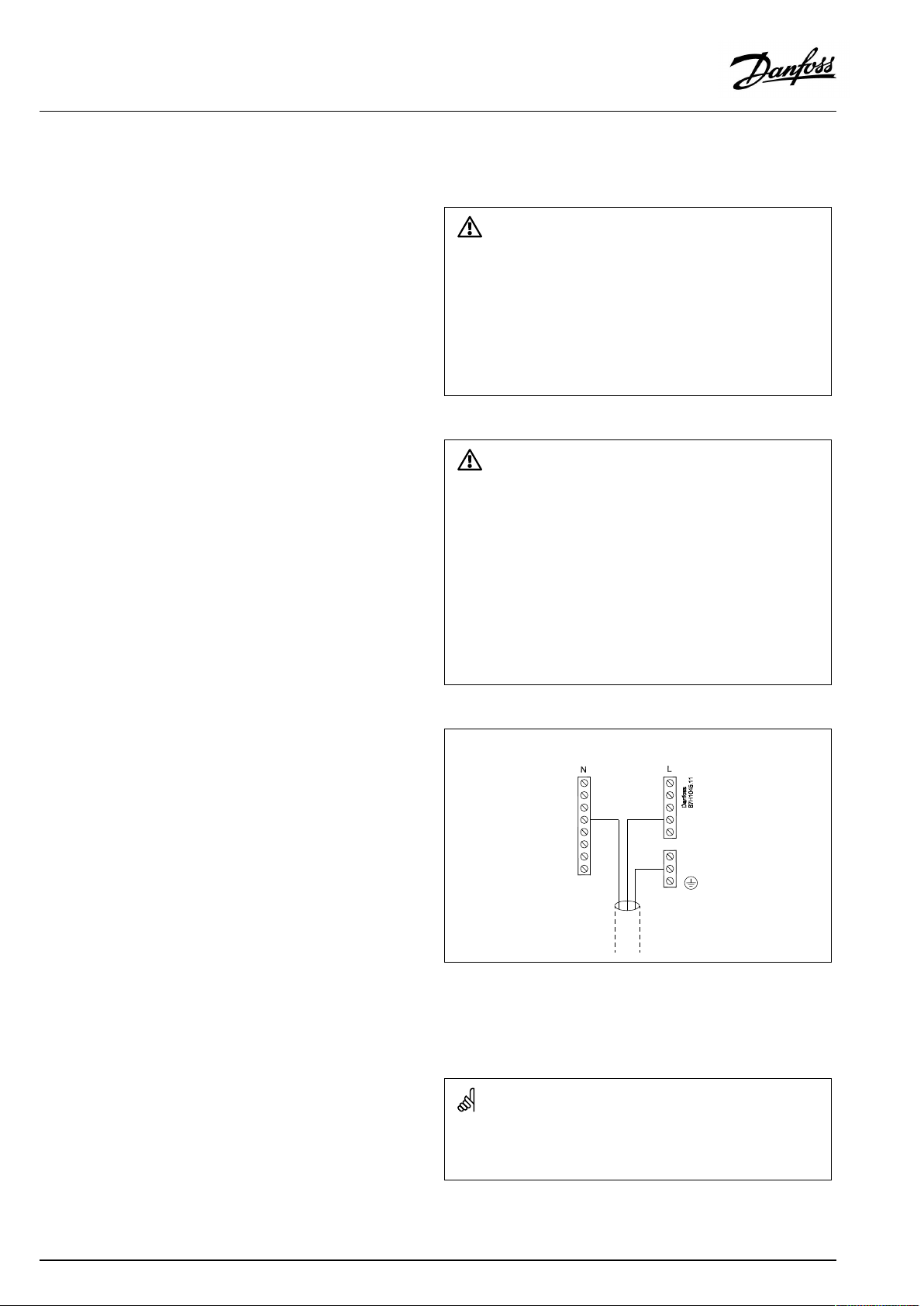
2.5Electricalconnections
2.5.1Electricalconnections230Va.c.
Warning
ElectricconductorsonPCB(PrintedCircuitBoard)forsupplyvoltage,
relaycontactsandtriacoutputsdonothavemutualsafetydistanceof
minimum6mm.Theoutputsarenotallowedtobeusedasgalvanic
separated(voltfree)outputs.
Ifagalvanicseparatedoutputisneeded,anauxiliaryrelayis
recommended.
24Voltcontrolledunits,forexampleactuators,aretobecontrolledby
meansofECLComfort310,24Voltversion.
SafetyNote
Necessaryassembly,start-up,andmaintenanceworkmustbe
performedbyqualifiedandauthorizedpersonnelonly.
Locallegislationsmustberespected.Thiscomprisesalsocablesize
andisolation(reinforcedtype).
Thecommongroundterminalisusedforconnectionofrelevant
components(pumps,motorizedcontrolvalves).
SeealsotheInstallationGuide(deliveredwiththeapplicationkey)
forapplicationspecificconnections.
AfusefortheECLComfortinstallationismax.10Atypically.
TheambienttemperaturerangefortheECLComfortinoperationis
0-55°C.Exceedingthistemperaturerangecanresultinmalfunctions.
Installationmustbeavoidedifthereisariskforcondensation(dew).
ECL210/310
22|©Danfoss|2021.06
Wirecrosssection:0.5-1.5mm²
Incorrectconnectioncandamagetheelectronicoutputs.
Max.2x1.5mm²wirescanbeinsertedintoeachscrewterminal.
AQ128686479024en-010601
Page 23
OperatingGuideECLComfort310,applicationA390
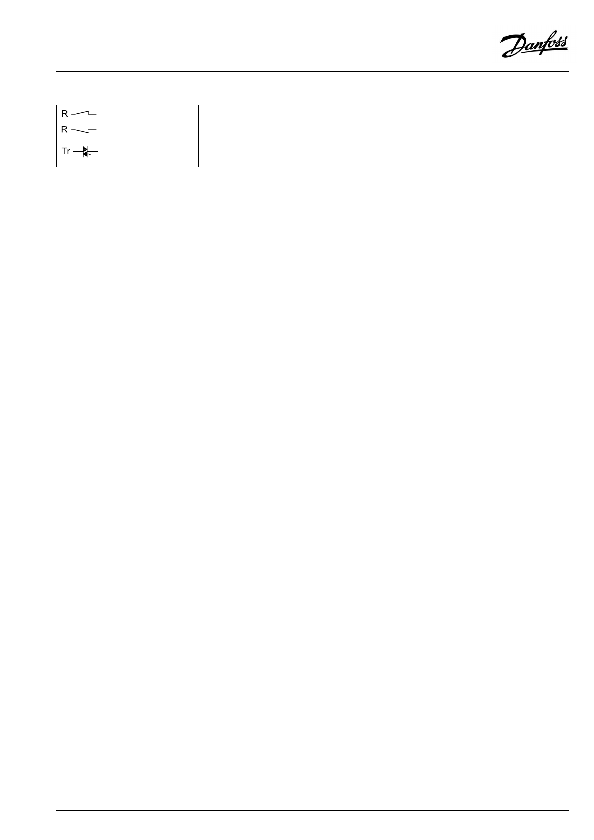
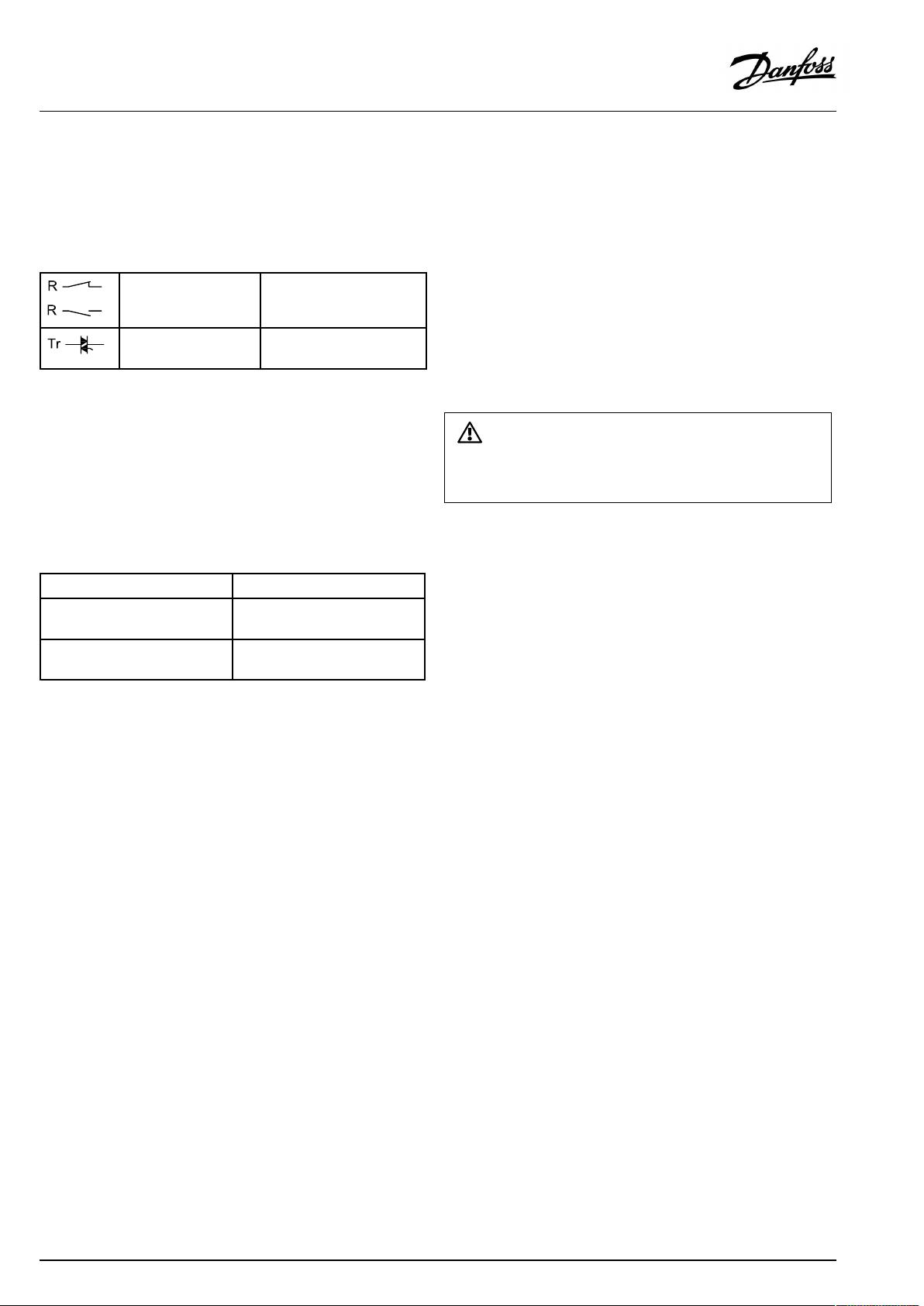
Maximumloadratings:
Relayterminals
Triac(=electronic
relay)terminals
4(2)A/230Va.c.
(4Aforohmicload,2Afor
inductiveload)
0,2A/230Va.c.
AQ128686479024en-010601
©Danfoss|2021.06|23
Page 24
OperatingGuideECLComfort310,applicationA390
2.5.2Electricalconnections24Va.c.
SeealsotheInstallationGuide(deliveredwiththeapplicationkey)
forapplicationspecificconnections.
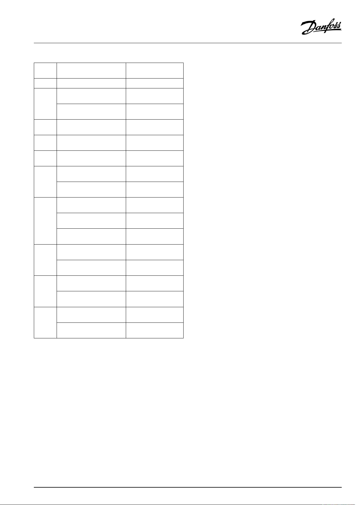
Maximumloadratings:
Relayterminals
Triac(=electronic
relay)terminals
Maximumloadrating,ECA32
Max.voltage,relayoutputs
Max.loadonrelayoutputs
Max.loadonanalogue
outputs
4(2)A/24Va.c.
(4Aforohmicload,2Afor
inductiveload)
1A/24Va.c.
250Va.c.
4Aforohmicload,2Afor
inductiveload
2mAeach(min.resistance
5KΩ)
Donotconnect230Va.c.poweredcomponentstoa24Va.c.power
suppliedcontrollerdirectly.Useauxilliaryrelays(K)toseparate230
Va.c.from24Va.c.
24|©Danfoss|2021.06
AQ128686479024en-010601
Page 25
OperatingGuideECLComfort310,applicationA390
2.5.3Electricalconnections,safetythermostats,ingeneral
SeealsotheInstallationGuide(deliveredwiththeapplicationkey)
forapplicationspecificconnections.
WhenSTisactivatedbyahightemperature,thesafetycircuitinthe
motorizedcontrolvalveclosesthevalveimmediately.
WhenST1isactivatedbyahightemperature(theTRtemperature),the
motorizedcontrolvalveisclosedgradually.Atahighertemperature
(theSTtemperature),thesafetycircuitinthemotorizedcontrolvalve
closesthevalveimmediately.
AQ128686479024en-010601
©Danfoss|2021.06|25
Page 26

OperatingGuideECLComfort310,applicationA390
2.5.4Electricalconnections,Pt1000temperaturesensorsandsignals
2.5.5Electricalconnections,Pt1000temperaturesensors
SeetheInstallationGuide(deliveredwiththeapplicationkey)for
sensorandinputconnections.
26|©Danfoss|2021.06
AQ128686479024en-010601
Page 27
OperatingGuideECLComfort310,applicationA390
A390:
Sensor
S1
S2
S3
S4
S5
S6
S7
S8
S9
S10
Description
Outdoortemp.sensor*
A390.1/2/3:Roomtemp.
sensor**
A390.11/12/13:Return
temp.sensor
Flowtemp.sensor***
Flowtemp.sensor***
Returntemp.sensor****ESM-11/ESMB/ESMC
A390.1/2/3:Returntemp.
sensor****
A390.11/12/13:DHWtank
temp.sensor,upper****
A390.1/2/3:Returntemp.
sensor****
A390.11/13:Roomtemp.
sensor**
A390.12:DHWcharging
temp.sensor****
A390.1/2/3:Roomtemp.
sensor**
A390.11/12/13:DHWtank
temp.sensor,lower****
A390.1/2/3/11/13:Flow
temp.sensor***
A390.12:DHWcharging
temp.sensor****
A390.1/2/3:Roomtemp.
sensor**
A390.11/12/13:Return
temp.sensor****
Type
(recomm.)
ESMT
ESM-10
ESM-11/ESMB/ESMC
/ESMU
ESM-11/ESMB/ESMC
/ESMU
ESM-11/ESMB/ESMC
/ESMU
/ESMU
ESM-11/ESMB/ESMC
/ESMU
ESMB/ESMU
ESM-11/ESMB/ESMC
/ESMU
ESM-10
ESM-11/ESMB/ESMC
/ESMU
ESM-10
ESMB/ESMU
ESM-11/ESMB/ESMC
/ESMU
ESM-11/ESMB/ESMC
/ESMU
ESM-10
ESM-11/ESMB/ESMC
/ESMU
*
Iftheoutdoortemperaturesensorisnotconnectedorthe
cableisshort-circuited,thecontrollerassumesthatthe
outdoortemperatureis0(zero)°C.
**
Onlyforroomtemperaturesensorconnection.Theroom
temperaturesignalcanalsobeavailablefromaRemote
ControlUnit(ECA30/31).See'Electricalconnections,ECA
30/31'.
***
Theflowtemperaturesensormustalwaysbeconnected
inordertohavethedesiredfunctionality.Ifthesensoris
notconnectedorthecableisshort-circuited,themotorized
controlvalvecloses(safetyfunction).
****
Thetemperaturesensormustbeconnectedinordertohave
thedesiredfunctionality.
AQ128686479024en-010601
©Danfoss|2021.06|27
Page 28
OperatingGuideECLComfort310,applicationA390
2.5.6Electricalconnections,ECA30/31
Wirecrosssectionforsensorconnections:Min.0.4mm².
Totalcablelength:Max.200m(allsensorsincl.internalECL485
communicationbus)
Cablelengthsofmorethan200mmaycausenoisesensibility(EMC).
Terminal
ECL
Terminal
ECA30/31
30
31
4
1
322
333
4
5
*
Afteranexternalroomtemperaturesensorhasbeenconnected,
Description
Twistedpair
Twistedpair
Ext.roomtemperature
sensor*
Type
(recomm.)
Cable2x
twistedpair
ESM-10
ECA30/31mustberepowered.
ThecommunicationtotheECA30/31mustbesetupintheECL
Comfortcontrollerin'ECAaddr.'
TheECA30/31mustbesetupaccordingly.
AfterapplicationsetuptheECA30/31isreadyafter2–5min.A
progressbarintheECA30/31isdisplayed.
Iftheactualapplicationcontainstwoheatingcircuits,itispossible
toconnectanECA30/31toeachcircuit.Theelectricalconnections
aredoneinparallel.
28|©Danfoss|2021.06
Max.2ECA30/31canbeconnectedtoanECLComfort310controller
ortoECLComfort210/296/310controllersinamaster-slavesystem.
ECAinformationmessage:
‘Applicationreq.newerECA’:
Thesoftware(firmware)ofyourECAdoesnotcomplywiththe
software(firmware)ofyourECLComfortcontroller.Pleasecontact
yourDanfosssalesoffice.
AQ128686479024en-010601
Page 29
OperatingGuideECLComfort310,applicationA390
Someapplicationsdonotcontainfunctionsrelatedtoactualroom
temperature.TheconnectedECA30/31willonlyfunctionasremote
control.
SetupproceduresforECA30/31:Seesection‘Miscellaneous’ .
Totalcablelength:Max.200m(allsensorsincl.internalECL485
communicationbus).
Cablelengthsofmorethan200mmaycausenoisesensibility(EMC).
AQ128686479024en-010601
©Danfoss|2021.06|29
Page 30
OperatingGuideECLComfort310,applicationA390
2.5.7Electricalconnections,master/slavesystems
Thecontrollercanbeusedasmasterorslaveinmaster/slave
systemsviatheinternalECL485communicationbus(2xtwisted
paircable).
TheECL485communicationbusisnotcompatiblewiththeECL
businECLComfort110,200,300and301!
Terminal
Description
Type
(recomm.)
30
Commonterminal
+12V*,ECL485communicationbus
31
*OnlyforECA30/31andmaster/
slavecommunication
32
B,ECL485communicationbus
33
A,ECL485communicationbus
Cable2x
twistedpair
ECL485buscable
MaximumrecommendedlengthoftheECL485busiscalculatedlike
this:
Subtract"TotallengthofallinputcablesofallECLcontrollersinthe
master-slavesystem"from200m.
Simpleexamplefortotallengthofallinputcables,3xECL:
1xECL
3xECL
3xECLReturntemp.sensor:
3xECLRoomtemp.sensor:
Total:
Outdoortemp.sensor:
Flowtemp.sensor:
15m
18m
18m
30m
81m
2.5.8Electricalconnections,communication
Electricalconnections,Modbus
ECLComfort210:Non-galvanicisolatedModbusconnections
ECLComfort296:GalvanicisolatedModbusconnections
ECLComfort310:GalvanicisolatedModbusconnections
MaximumrecommendedlengthoftheECL485bus:
200-81m=119m
30|©Danfoss|2021.06
AQ128686479024en-010601
Page 31

OperatingGuideECLComfort310,applicationA390
2.5.9Electricalconnections,communication
Electricalconnections,M-bus
ECLComfort210:Notimplemented
ECLComfort296:Onboard,non-galvanicisolated.Max.cable
length50m.
ECLComfort310:Onboard,non-galvanicisolated.Max.cable
length50m.
AQ128686479024en-010601
©Danfoss|2021.06|31
Page 32

OperatingGuideECLComfort310,applicationA390
2.6InsertingtheECLApplicationKey
2.6.1InsertingtheECLApplicationKey
TheECLApplicationKeycontains
•theapplicationanditssubtypes,
•currentlyavailablelanguages,
•factorysettings:e.g.schedules,desiredtemperatures,
limitationvaluesetc.Itisalwayspossibletorecoverthefactory
settings,
•memoryforusersettings:specialuser/systemsettings.
Afterhavingpowered-upthecontroller,differentsituationsmight
beexisting:
1.Thecontrollerisnewfromthefactory,theECLApplicationKey
isnotinserted.
2.Thecontrolleralreadyrunsanapplication.TheECLApplication
Keyisinserted,buttheapplicationneedstobechanged.
3.Acopyofthecontrollerssettingsisneededforconfiguring
anothercontroller.
ECLComfort210/310
ECLComfort210/310
Usersettingsare,amongothers,desiredroomtemperature,desired
DHWtemperature,schedules,heatcurve,limitationvaluesetc.
Systemsettingsare,amongothers,communicationset-up,display
brightnessetc.
32|©Danfoss|2021.06
ECLComfort296
AQ128686479024en-010601
Page 33

OperatingGuideECLComfort310,applicationA390
Automaticupdateofcontrollersoftware(firmware):
Thesoftwareofthecontrollerisupdatedautomaticallywhenthekey
isinserted(asofcontrollerversion1.11(ECL210/310)andversion
1.58(ECL296)).Thefollowinganimationwillbeshownwhenthe
softwareisbeingupdated:
Progressbar
Duringupdate:
•DonotremovetheKEY
Ifthekeyisremovedbeforethehour-glassisshown,youhave
tostartafresh.
•Donotdisconnectthepower
Ifthepowerisinterruptedwhenthehour-glassisshown,the
controllerwillnotwork.
•Manualupdateofcontrollersoftware(firmware):
Seethesection"Automatic/manualupdateoffirmware"
The“Keyoverview”doesnotinform—throughECA30/31—about
thesubtypesoftheapplicationkey.
Keyinserted/notinserted,description:
ECLComfort210/310,controllerversionslowerthan1.36:
-
Takeouttheapplicationkey;for20minutes
settingscanbechanged.
-
Powerupthecontrollerwithoutthe
applicationkeyinserted;for20minutes
settingscanbechanged.
ECLComfort210/310,controllerversions1.36andup:
-
Takeouttheapplicationkey;for20minutes
settingscanbechanged.
-
Powerupthecontrollerwithoutthe
applicationkeyinserted;settingscannotbe
changed.
ECLComfort296,controllerversions1.58andup:
-
Takeouttheapplicationkey;for20minutes
settingscanbechanged.
-
Powerupthecontrollerwithoutthe
applicationkeyinserted;settingscannotbe
changed.
AQ128686479024en-010601
©Danfoss|2021.06|33
Page 34

OperatingGuideECLComfort310,applicationA390
ApplicationKey:Situation1
Thecontrollerisnewfromthefactory,theECLApplicationKey
isnotinserted.
AnanimationfortheECLApplicationKeyinsertionisdisplayed.
InserttheApplicationKey.
ApplicationKeynameandVersionisindicated(example:A266
Ver.1.03).
IftheECLApplicationKeyisnotsuitableforthecontroller,a"cross"
isdisplayedovertheECLApplicationKey-symbol.
Action:Purpose:
Selectlanguage
Confirm
Selectapplication(subtype)
Somekeyshaveonlyoneapplication.
Confirmwith‘Yes’
Set'Time&Date'
Turnandpushthedialtoselectand
change'Hours' ,'Minutes','Date',
'Month'and'Year' .
Choose''Next'
Confirmwith‘Yes’
Goto‘Aut.daylight’
Choosewhether‘ Aut.daylight´*
shouldbeactiveornot
*‘Aut.daylight’istheautomaticchangeoverbetweensummer
andwintertime.
DependingonthecontentsoftheECLApplicationKey,procedure
AorBistakingplace:
A
TheECLApplicationkeycontainsfactorysettings:
Thecontrollerreads/transfersdatafromtheECLApplicationKey
toECLcontroller.
Examples:
YESorNO
Theapplicationisinstalled,andthecontrollerresetsandstartsup.
B
TheECLApplicationkeycontainschangedsystemsettings:
Pushthedialrepeatedly.
’NO’:
’YES*:
Ifthekeycontainsusersettings:
Pushthedialrepeatedly.
‘NO:
‘YES*:
*If‘YES’cannotbechosen,theECLApplicationKeydoesnot
containanyspecialsettings.
Choose‘Startcopying’andconfirmwith'Yes'.
34|©Danfoss|2021.06
OnlyfactorysettingsfromtheECLApplicationKeywill
becopiedtothecontroller.
Specialsystemsettings(differingfromthefactory
settings)willbecopiedtothecontroller.
OnlyfactorysettingsfromtheECLApplicationKeywill
becopiedtothecontroller.
Specialusersettings(differingfromthefactorysettings)
willbecopiedtothecontroller.
AQ128686479024en-010601
Page 35

OperatingGuideECLComfort310,applicationA390
(Example):
The"i"intheupperrightcornerindicatesthat-besidesthefactory
settings-thesubtypealsocontainsspecialuser/systemssettings.
ApplicationKey:Situation2
Thecontrolleralreadyrunsanapplication.TheECLApplication
Keyisinserted,buttheapplicationneedstobechanged.
TochangetoanotherapplicationontheECLApplicationKey,the
currentapplicationinthecontrollermustbeerased(deleted).
BeawarethattheApplicationKeymustbeinserted.
Action:Purpose:
Choose‘MENU’inanycircuit
Confirm
Choosethecircuitselectoratthetop
rightcornerinthedisplay
Confirm
Choose‘Commoncontrollersettings’
Confirm
Choose‘Keyfunctions’
Confirm
Choose‘Eraseapplication’
Confirmwith‘Yes’
Thecontrollerresetsandisreadytobeconfigured.
Followtheproceduredescribedinsituation1.
Examples:
AQ128686479024en-010601
©Danfoss|2021.06|35
Page 36

OperatingGuideECLComfort310,applicationA390
ApplicationKey:Situation3
Acopyofthecontrollerssettingsisneededforconfiguring
anothercontroller.
Thisfunctionisused
•forsaving(backup)ofspecialuserandsystemsettings
•whenanotherECLComfortcontrollerofthesametype(210,
296or310)mustbeconfiguredwiththesameapplicationbut
user/systemsettingsdifferfromthefactorysettings.
HowtocopytoanotherECLComfortcontroller:
Action:Purpose:
Choose‘MENU’
Confirm
Choosethecircuitselectoratthetop
rightcornerinthedisplay
Confirm
Choose'Commoncontrollersettings'
Confirm
Goto‘Keyfunctions’
Confirm
Choose‘Copy’
Confirm
Choose‘To’ .
‘ECL’or‘KEY’willbeindicated.Choose
’ECL’orKEY’
Pushthedialrepeatedlytochoose
copydirection
Choose‘Systemsettings’or‘User
settings’
Pushthedialrepeatedlytochoose
‘Yes’or‘No’in‘Copy’ .Pushtoconfirm.
Choose‘Startcopying’
TheApplicationKeyorthecontroller
isupdatedwithspecialsystemoruser
settings.
Examples:
*
’ECL’or‘KEY’ .
**
‘NO’or‘YES’
*
‘ECL’:
‘KEY’:
**
‘NO’:
‘YES’:
36|©Danfoss|2021.06
DatawillbecopiedfromtheApplicationKeytothe
ECLController.
DatawillbecopiedfromtheECLControllertothe
ApplicationKey.
ThesettingsfromtheECLcontrollerwillnotbecopied
totheApplicationKeyortotheECLComfortcontroller.
Specialsettings(differingfromthefactorysettings)will
becopiedtotheApplicationKeyortotheECLComfort
controller.IfYEScannotbechosen,therearenospecial
settingstobecopied.
AQ128686479024en-010601
Page 37

OperatingGuideECLComfort310,applicationA390
Language
Atapplicationupload,alanguagemustbeselected.*
IfanotherlanguagethanEnglishisselected,theselectedlanguage
ANDEnglishwillbeuploadedintotheECLcontroller.
ThismakesserviceeasyforEnglishspeakingservicepeople,just
becausetheEnglishlanguagemenuscanbevisiblebychanging
theactualsetlanguageintoEnglish.
(Navigation:MENU>Commoncontroller>System>Language)
Iftheuploadedlanguageisnotsuitable,theapplicationmustbe
erased.UserandSystemsettingscanbesavedontheapplication
keybeforeerasing.
Afternewuploadwithpreferredlanguage,theexistingUserand
Systemsettingscanbeuploaded.
*)
(ECLComfort310,24Volt)Iflanguagecannotbeselected,the
powersupplyisnota.c.(alternatingcurrent).
2.6.2ECLApplicationKey,copyingdata
Generalprinciples
Whenthecontrollerisconnectedandoperating,youcancheck
andadjustallorsomeofthebasicsettings.Thenewsettingscan
bestoredontheKey.
Factorysettingscanalwaysberestored.
HowtoupdatetheECLApplicationKeyaftersettingshave
beenchanged?
AllnewsettingscanbestoredontheECLApplicationKey.
Howtostorefactorysettinginthecontrollerfromthe
ApplicationKey?
PleasereadtheparagraphconcerningApplicationKey,Situation
1:Thecontrollerisnewfromthefactory,theECLApplicationKey
isnotinserted.
HowtostorepersonalsettingsfromthecontrollertotheKey?
PleasereadtheparagraphconcerningApplicationKey,Situation3:
Acopyofthecontrollerssettingsisneededforconfiguringanother
controller
Asamainrule,theECLApplicationKeyshouldalwaysremainin
thecontroller.IftheKeyisremoved,itisnotpossibletochange
settings.
Makeanoteofnewsettingsinthe'Settingsoverview'table.
DonotremovetheECLApplicationKeywhilecopying.Thedataon
theECLApplicationKeycanbedamaged!
ItispossibletocopysettingsfromoneECLComfortcontrollerto
anothercontrollerprovidedthatthetwocontrollersarefromthesame
series(210or310).
Furthermore,whentheECLComfortcontrollerhasbeenuploaded
withanapplicationkey,minimumversion2.44,itispossibletoupload
personalsettingsfromapplicationkeys,minimumversion2.14.
AQ128686479024en-010601
©Danfoss|2021.06|37
Page 38

OperatingGuideECLComfort310,applicationA390
The“Keyoverview”doesnotinform—throughECA30/31—about
thesubtypesoftheapplicationkey.
Keyinserted/notinserted,description:
ECLComfort210/310,controllerversionslowerthan1.36:
-
Takeouttheapplicationkey;for20minutes
settingscanbechanged.
-
Powerupthecontrollerwithoutthe
applicationkeyinserted;for20minutes
settingscanbechanged.
ECLComfort210/310,controllerversions1.36andup:
-
Takeouttheapplicationkey;for20minutes
settingscanbechanged.
-
Powerupthecontrollerwithoutthe
applicationkeyinserted;settingscannotbe
changed.
ECLComfort296,controllerversions1.58andup:
-
Takeouttheapplicationkey;for20minutes
settingscanbechanged.
-
Powerupthecontrollerwithoutthe
applicationkeyinserted;settingscannotbe
changed.
38|©Danfoss|2021.06
AQ128686479024en-010601
Page 39

OperatingGuideECLComfort310,applicationA390
2.7Checklist
IstheECLComfortcontrollerreadyforuse?
Makesurethatthecorrectpowersupplyisconnectedtoterminals9and10(230Vor24V).
Makesurethecorrectphaseconditionsareconnected:
230V:Live=terminal9andNeutral=terminal10
24V:SP=terminal9andSN=terminal10
Checkthattherequiredcontrolledcomponents(actuator,pumpetc.)areconnectedtothecorrectterminals.
Checkthatallsensors/signalsareconnectedtothecorrectterminals(see'Electricalconnections').
Mountthecontrollerandswitchonthepower.
IstheECLApplicationKeyinserted(see'InsertingtheApplicationKey').
DoestheECLComfortcontrollercontainanexistingapplication(see'InsertingtheApplicationKey').
Isthecorrectlanguagechosen(see'Language'in'Commoncontrollersettings').
Isthetime&datesetcorrectly(see'Time&Date'in'Commoncontrollersettings').
Istherightapplicationchosen(see'Identifyingthesystemtype').
Checkthatallsettingsinthecontroller(see'Settingsoverview')aresetorthatthefactorysettingscomplywithyour
requirements.
Choosemanualoperation(see'Manualcontrol').Checkthatvalvesopenandclose,andthatrequiredcontrolled
components(pumpetc.)startandstopwhenoperatedmanually.
Checkthatthetemperatures/signalsshowninthedisplaymatchtheactualconnectedcomponents.
Havingcompletedthemanualoperationcheck,choosecontrollermode(scheduled,comfort,savingorfrostprotection).
AQ128686479024en-010601
©Danfoss|2021.06|39
Page 40

OperatingGuideECLComfort310,applicationA390
2.8Navigation,ECLApplicationKeyA390
Parameterlist,applicationA390,Heating
Home
MENU
ScheduleSchedule
Settings
Sub-menu
IDnos.
Flow
temperature
Roomlimit
Returnlimit
Flow/Actual
powerlimitActuallimit
Optimization
1x178
1x177
1x004
1x182
1x183
1x015
1x031
1x032
1x033
1x034
1x035
1x036
1x037
1x085
11029
1x028
1x119
1x117
1x118
1x116
1x112
1x113
1x10⁹
1x115
1x011
1x012
1x013
1x014
1x026
1x020
1x021
1x179
11043
Function
Heatcurve
Temp.max.
Temp.min.
DesiredT
Infl.-max.
Infl.-min.
Adapt.time
HighToutX1
LowlimitY1
LowToutX2
HighlimitY2
Infl.-max.
Infl.-min.
Adapt.time
Priority
DHW,ret.Tlimit
Con.T,ret.Tlim.
HighToutX1
LowlimitY1
LowToutX2
HighlimitY2
Adapt.time
Filterconstant
Inputtype
Units
Autosaving
Boost
Ramp
Optimizer
Pre-stop
Basedon
Totalstop
Summer,cut-out
Paralleloperation
A390
A390.1A390.2A390.11A390.12A390.13
(((((
(((((
(((((
(((((
(((((
(((((
(((((
(((((
(((((
(((((
(((((
(((((
(((((
(((((
(((((
(((((
(((
(((((
(((((
(((((
(((((
(((((
(((((
(((((
(((((
(((((
(((((
(((((
(((((
(((((
(((((
(((((
(((((
(((((
(((((
(((((
(
40|©Danfoss|2021.06
AQ128686479024en-010601
Page 41

OperatingGuideECLComfort310,applicationA390
Parameterlist,applicationA390,Heating,continued
Home
MENU
Settings
HolidayHoliday
Alarm
Influence
overview
Sub-menu
IDnos.
Controlpar.
Application
Heatcut-out
Temp.monitor
Alarmoverview
Des.flowTInfluencesource
1x174
1x184
1x185
1x186
1x187
1x189
1x024
1x010
11017
11050
1x500
1x022
1x023
1x052
1x077
1x078
1x040
1x093
1x141
1x142
11393
11392
1x179
1x395
11397
11396
1x398
1x399
1x147
1x148
1x149
1x150
Function
Motorpr
Xp
Tn
Mrun
Nz
Min.act.time
Actuator
ECAaddr.
Demandoffset
Pdemand
SenddesiredT
Pexercise
Mexercise
DHWpriority
PfrostT
PheatT
Ppost-run
Frostpr.T
Ext.input
Ext.mode
Sum.start,day
Sum.start,month
Summer,cut-out
Summer,filter
Winterstart,day
Win.start,month
Winter,cut-out
Winter,filter
Upperdifference
Lowerdifference
Delay
Lowesttemp.
A390
A390.1A390.2A390.11A390.12A390.13
(((((
(((((
(((((
((((
(((((
((((
((((
(((((
((((
((((
(((((
(((((
(((((
(((((
(((((
(((((
(((((
(((((
(((((
(((((
(((((
(((((
(((((
(((((
(((((
(((((
(((((
(((((
(((((
(((((
(((((
(((((
(((((
(((((
(((((
AQ128686479024en-010601
©Danfoss|2021.06|41
Page 42

OperatingGuideECLComfort310,applicationA390
Parameterlist,applicationA390,Cooling
Home
MENU
ScheduleSchedule
Settings
Sub-menu
IDnos.
Flow
temperature
Roomlimit
Returnlimit
Compensation1
Compensation2
Flow/Actual
powerlimit
Controlpar.
1x018
1x019
1x178
1x177
1x015
1x182
1x183
1x030
1x037
1x035
1x036
1x160
1x061
1x062
1x063
1x164
1x065
1x066
1x067
1x111
1x112
1x113
1x10⁹
1x115
1x114
1x174
1x184
1x185
1x186
1x187
1x189
1x024
Function
Des.Tcomfort
Des.Tsaving
Temp.max.
Temp.min
Adapt.time
Infl.-max.
Infl.-min.
Limit
Adapt.time
Infl.-max.
Infl.-min.
Limit
Adapt.time
Infl.-max.
Infl.-min.
Limit
Adapt.time
Infl.-max.
Infl.-min.
Limit
Adapt.time
Filterconstant
Inputtype
Units
Pulse
Motorpr
Xp
Tn
Mrun
Nz
Min.act.time
Actuator
A390
A390.3
(
(
(
(
(
(
(
(
(
(
(
(
(
(
(
(
(
(
(
(
(
(
(
(
(
(
(
(
(
(
(
(
(
(
42|©Danfoss|2021.06
AQ128686479024en-010601
Page 43

OperatingGuideECLComfort310,applicationA390
Parameterlist,applicationA390,Cooling,continued
Home
MENU
Settings
HolidayHoliday
InfluenceoverviewDes.flowTInfluencesource
Sub-menu
Application
IDnos.
1x010
11017
11050
1x500
1x022
1x023
1x070
1x092
1x040
1x141
1x142
Function
ECAaddr.
Demandoffset
Pdemand
SenddesiredT
Pexercise
Mexercise
PcoolT
StandbyT
Ppost-run
Ext.input
Ext.mode
A390
A390.3
(
(
(
(
(
(
(
(
(
(
(
(
(
AQ128686479024en-010601
©Danfoss|2021.06|43
Page 44

OperatingGuideECLComfort310,applicationA390
Parameterlist,applicationA390,DHW
Home
MENU
ScheduleSchedule
Schedulecirc.PSchedulecirc.P
Settings
Sub-menu
IDnos.
Tank
temperature
Returnlimit
Flow/powerlimitActual
Contr.par.
Application
13178
13177
1x193
1x195
1x194
1x152
13068
1x030
1x035
1x036
1x037
1x111
13112
13113
13109
13115
1x174
1x184
1x185
1x186
1x187
1x189
13017
13050
14051
14053
1x055
1x054
1x044
1x045
1x041
1x059
1x042
1x500
1x076
1x093
1x141
1x142
Function
Temp.max.
Temp.min.
Chargedifference
Startdifference
Stopdifference
Max.chargeT
FlowTadapt.time
Limit
Infl.-max.
Infl.-min.
Adapt.time
Limit
Adapt.time
Filterconstant
Inputtype
Units
Motorpr
Xp
Tn
Mrun
Nz
Min.act.time
Demandoffset
Pdemand
Ch.-o.valve/P
Tank,sec./prim.
Circ.Ppriority
Contr.Tcontrol
Max.DHWtime
DHWdeact.time
DHWPpost-run
Pchargedelay
Char.Ppost-run
SenddesiredT
Circ.PfrostT
Frostpr.T
Ext.input
Ext.mode
A390
A390.11A390.12A390.13
(((
(((
(
(
(((
(((
(((
((
(
(((
((
((
((
(((
(((
((
((
((
((
((
((
((
((
((
((
(
(
(
(
(((
((
((
((
(((
(((
(((
(((
(((
(((
(((
(((
44|©Danfoss|2021.06
AQ128686479024en-010601
Page 45

OperatingGuideECLComfort310,applicationA390
Parameterlist,applicationA390,DHW,continued
Home
MENU
Settings
HolidayHoliday
Alarm
InfluenceoverviewDes.flowTInfluencesource
Sub-menu
IDnos.
Anti-bacteriaDay,days
Temp.monitor
Alarmoverview
1x147
1x148
1x149
1x150
Function
Starttime
Duration
DesiredT
Upperdifference
Lowerdifference
Delay
Lowesttemp.
A390
A390.11A390.12A390.13
(((
(((
(((
(((
(((
((
((
((
((
((
(((
AQ128686479024en-010601
©Danfoss|2021.06|45
Page 46

OperatingGuideECLComfort310,applicationA390
Parameterlist,applicationA390,Commoncontroller
Home
MENU
Sub-menu
Time&date
Schedule
Holiday
Inputoverview1
Inputoverview2
Inputoverview3
Inputoverview4
Log1
Log2
Log3
Log4
Outputoverride
Keyfunctions
System
IDnos.
Function
Newapplication
Application
Factorysetting
Copy
Keyoverview
ECLversion
Extension
Ethernet
Portalconfig.
M-busconfig.
Energymeters
Rawinput
overview
Alarm
Display
Communication
Language
A390.1A390.2A390.3A390.11A390.12A390.13
((((((
((
((
((
((
((
((
((
((
((
((
((
((
((
((
((
((
((
((
((
((
((
((
((
((
A390
(
((((
((((
((((
((((
(
((((
((((
((((
(
((((
((((
((((
((((
((((
((((
((((
((((
((((
((((
((((
((((
((((
((((
((((
((((
((((
46|©Danfoss|2021.06
AQ128686479024en-010601
Page 47

OperatingGuideECLComfort310,applicationA390
3.0Dailyuse
3.1Howtonavigate
Younavigateinthecontrollerbyturningthedialleftorrightto
thedesiredposition().
Thedialhasabuilt-inaccellerator.Thefasteryouturnthedial,the
fasteritreachesthelimitsofanywidesettingrange.
Thepositionindicatorinthedisplay(
youare.
Pushthedialtoconfirmyourchoices().
Thedisplayexamplesarefromatwo-circuitapplication:One
heatingcircuit()andonedomestichot-water(DHW)circuit().
Theexamplesmightdifferfromyourapplication.
)willalwaysshowyouwhere
ExampleshowsECL210/310
Heatingcircuit():DHWcircuit();
Somegeneralsettingswhichapplytotheentirecontrollerare
locatedinaspecificpartofthecontroller.
Toenter‘Commoncontrollersettings’:
Action:Purpose:
Choose‘MENU’inanycircuit
Confirm
Choosethecircuitselectoratthetop
rightcornerinthedisplay
Confirm
Choose‘Commoncontrollersettings’
Confirm
Examples:
Circuitselector
AQ128686479024en-010601
©Danfoss|2021.06|47
Page 48

OperatingGuideECLComfort310,applicationA390
3.2Understandingthecontrollerdisplay
ThissectiondescribesthefunctioningeneralfortheECLComfort
210/296/310series.Theshowndisplaysaretypicalandnot
applicationrelated.Theymightdifferfromthedisplaysinyour
application.
Choosingafavoritedisplay
Yourfavoritedisplayisthedisplayyouhavechosenasthedefault
display.Thefavoritedisplaywillgiveyouaquickoverviewofthe
temperaturesorunitsthatyouwanttomonitoringeneral.
Ifthedialhasnotbeenactivatedfor20min.,thecontrollerwill
reverttotheoverviewdisplayyouhavechosenasfavorite.
Toshiftbetweendisplays:Turnthedialuntilyoureachthedisplay
selector(
turntochooseyourfavoriteoverviewdisplay.Pushthedialagain.
)atthebottomrightsideofthedisplay.Pushthedialand
Heatingcircuit
Overviewdisplay1informsabout:
actualoutdoortemperature,controllermode,
actualroomtemperature,desiredroomtemperature.
Overviewdisplay2informsabout:
actualoutdoortemperature,trendinoutdoortemperature,
controllermode,max.andmin.outdoortemperaturessince
midnightaswellasdesiredroomtemperature.
Overviewdisplay3informsabout:
date,actualoutdoortemperature,controllermode,time,desired
roomtemperatureaswellasshowsthecomfortscheduleofthe
currentday.
Overviewdisplay4informsabout:
stateofthecontrolledcomponents,actualflowtemperature,
(desiredflowtemperature),controllermode,returntemperature
(limitationvalue),influenceondesiredflowtemperature.
ThevalueabovetheV2symbolindicates0–100%oftheanalogue
signal(0–10V).
Note:
Anactualflowtemperaturevaluemustbepresent,otherwisethe
circuit'scontrolvalvewillclose.
Overviewdisplay1:Overviewdisplay2:
Overviewdisplay3:Overviewdisplay4:
Exampleofoverviewdisplaywith
Influenceindication:
Example,favoritedisplay1in
A230.3,wheremin.desiredroom
temperatureisindicated(22.7):
Dependentonthechosendisplay,theoverviewdisplaysforthe
heatingcircuitinformyouabout:
•actualoutdoortemperature(-0.5)
•controllermode()
•actualroomtemperature(24.5)
•desiredroomtemperature(20.7°C)
•trendinoutdoortemperature(
)
•min.andmax.outdoortemperaturessincemidnight(
•date(23.02.2010)
•time(7:43)
•comfortscheduleofthecurrentday(0-12-24)
•stateofthecontrolledcomponents(M2,P2)
•actualflowtemperature(49°C),(desiredflowtemperature(31))
•returntemperature(24°C)(limitationtemperature(50))
48|©Danfoss|2021.06
)
AQ128686479024en-010601
Page 49

OperatingGuideECLComfort310,applicationA390
Settingthedesiredtemperature
Dependingonthechosencircuitandmode,itispossibletoenter
alldailysettingsdirectlyfromtheoverviewdisplays(seealsothe
nextpageconcerningsymbols).
Thesettingofthedesiredroomtemperatureisimportantevenifa
roomtemperaturesensor/RemoteControlUnitisnotconnected.
Ifthetemperaturevalueisdisplayedas
"--"
thesensorinquestionisnotconnected.
"---"
thesensorconnectionisshort-circuited.
Settingthedesiredroomtemperature
Thedesiredroomtemperaturecaneasilybeadjustedinthe
overviewdisplaysfortheheatingcircuit.
Action:Purpose:
Examples:
Desiredroomtemperature
Confirm
Adjustthedesiredroomtemperature
Confirm
Thisoverviewdisplayinformsaboutoutdoortemperature,actual
roomtemperatureaswellasdesiredroomtemperature.
Thedisplayexampleisforcomfortmode.Ifyouwanttochange
thedesiredroomtemperatureforsavingmode,choosethemode
selectorandselectsaving.
20.5
21.0
Thesettingofthedesiredroomtemperatureisimportantevenifa
roomtemperaturesensor/RemoteControlUnitisnotconnected.
AQ128686479024en-010601
©Danfoss|2021.06|49
Page 50

OperatingGuideECLComfort310,applicationA390
SettingthedesiredDHWtemperature
ThedesiredDHWtemperaturecaneasilybeadjustedinthe
overviewdisplaysfortheDHWcircuit.
Action:Purpose:
DesiredDHWtemperature
Examples:
50
Confirm
AdjustthedesiredDHWtemperature
55
Confirm
InadditiontotheinformationaboutdesiredandactualDHW
temperature,thetoday'sscheduleisvisible.
Thedisplayexampleindicatesthatthecontrollerisinscheduled
operationandincomfortmode.
Settingthedesiredroomtemperature,ECA30/ECA31
Thedesiredroomtemperaturecanbesetexactlyasinthe
controller.However,othersymbolscanbepresentinthedisplay
(pleasesee'Whatdothesymbolsmean?').
WiththeECA30/ECA31youcanoverridethedesiredroom
temperaturesetinthecontrollertemporarilybymeansoftheoverride
functions:
50|©Danfoss|2021.06
AQ128686479024en-010601
Page 51

OperatingGuideECLComfort310,applicationA390
3.3Ageneraloverview:Whatdothesymbolsmean?
Symbol
Description
Outdoortemp.
Relativehumidityindoor
Roomtemp.
DHWtemp.
Positionindicator
Scheduledmode
Comfortmode
Savingmode
Frostprotectionmode
Manualmode
Standby
Coolingmode
Symbol
Temperature
Mode
Description
Alarm
Letter
Event
Monitoringtemperaturesensor
connection
Displayselector
Max.andmin.value
Trendinoutdoortemperature
Windspeedsensor
Sensornotconnectedornotused
Sensorconnectionshort-circuited
Fixedcomfortday(holiday)
Activeinfluence
Heatingactive(+)
Coolingactive(-)
Activeoutputoverride
Optimizedstartorstoptime
Heating
Cooling
DHW
Commoncontrollersettings
PumpON
PumpOFF
FanON
FanOFF
Actuatoropens
Actuatorcloses
Actuator,analoguecontrol
signal
Pump/fanspeed
DamperON
Circuit
Controlled
component
Numberofheatexchangers
Additionalsymbols,ECA30/31:
Symbol
InECA30/31onlythesymbolsthatarerelevanttotheapplicationin
thecontrolleraredisplayed.
Description
ECARemoteControlUnit
Connectionaddress(master:15,slaves:1-9)
15
Dayoff
Holiday
Relaxing(extendedcomfortperiod)
Goingout(extendedsavingperiod)
DamperOFF
AQ128686479024en-010601
©Danfoss|2021.06|51
Page 52

OperatingGuideECLComfort310,applicationA390
3.4Monitoringtemperaturesandsystemcomponents
ThissectiondescribesthefunctioningeneralfortheECLComfort
210/296/310series.Theshowndisplaysaretypicalandnot
applicationrelated.Theymightdifferfromthedisplaysinyour
application.
Heatingcircuit
Theoverviewdisplayintheheatingcircuitensuresaquick
overviewoftheactualand(desired)temperaturesaswellasthe
actualstateofthesystemcomponents.
Displayexample:
49°C
(31)
24°C
(50)
DHWcircuit
TheoverviewdisplayintheDHWcircuitensuresaquickoverview
oftheactualand(desired)temperaturesaswellastheactualstate
ofthesystemcomponents.
Displayexample(heatexchanger):
50°C
(50)
(30)
Flowtemperature
Desiredflowtemperature
Returntemperature
Returntemperaturelimitation
Flowtemperature
Desiredflowtemperature
--
Returntemperature:sensornotconnected
Returntemperaturelimitation
Displayexamplewithheatexchanger:
Inputoverview
Anotheroptiontogetaquickoverviewofmeasuredtemperatures
isthe'Inputoverview'whichisvisibleinthecommoncontroller
settings(howtoenterthecommoncontrollersettings,see
‘Introductiontocommoncontrollersettings’ .)
Asthisoverview(seedisplayexample)onlystatesthemeasured
actualtemperatures,itisread-only.
52|©Danfoss|2021.06
AQ128686479024en-010601
Page 53

OperatingGuideECLComfort310,applicationA390
3.5Influenceoverview
ThissectiondescribesthefunctioningeneralfortheECLComfort
210/296/310series.Theshowndisplaysaretypicalandnot
applicationrelated.Theymightdifferfromthedisplaysinyour
application.
Themenugivesanoverviewoftheinfluencesonthedesired
flowtemperature.Itdiffersfromapplicationtoapplicationwhich
parametersarelisted.Itcanbehelpfulinaservicesituationto
explainunexpectedconditionsortemperaturesamongothers.
Ifthedesiredflowtemperatureisinfluenced(corrected)byoneor
moreparameters,itisindicatedbyasmalllinewitharrow-down,
arrow-upordouble-arrow:
Arrow-down:
Theparameterinquestionreducesthedesiredflowtemperature.
Arrow-up:
Theparameterinquestionincreasesthedesiredflowtemperature.
Double-arrow:
Theparameterinquestioncreatesanoverride(e.g.Holiday).
Straightline:
Noactiveinfluence.
Intheexample,thearrowinthesymbolpointsdownwardsfor
'Roomlim. ' .Thismeansthattheactualroomtemperatureis
higherthanthedesiredroomtemperaturewhichagainresultsina
decreaseofthedesiredflowtemperature.
ExampleofoverviewdisplaywithInfluenceindication:
AQ128686479024en-010601
©Danfoss|2021.06|53
Page 54

OperatingGuideECLComfort310,applicationA390
3.6Manualcontrol
ThissectiondescribesthefunctioningeneralfortheECLComfort
210/296/310series.Theshowndisplaysaretypicalandnot
applicationrelated.Theymightdifferfromthedisplaysinyour
application.
Itispossibletomanuallycontroltheinstalledcomponents.
Manualcontrolcanonlybeselectedinfavoritedisplaysinwhich
thesymbolsforthecontrolledcomponents(valve,pumpetc.)are
visible.
Action:Purpose:
Choosemodeselector
Confirm
Choosemanualmode
Confirm
Choosepump
Confirm
SwitchONthepump
SwitchOFFthepump.
Confirmpumpmode
Choosemotorizedcontrolvalve
Confirm
Openthevalve
Stopopeningthevalve
Closethevalve
Examples:
ControlledcomponentsCircuitselector
Duringmanualoperation:
•Allcontrolfunctionsaredeactivated
•Outputoverrideisnotpossible
•Frostprotectionisnotactive
Stopclosingthevalve
Confirmvalvemode
Toleavemanualcontrol,usethemodeselectortoselectthe
desiredmode.Pushthedial.
Manualcontrolistypicallyusedwhencommisioningthe
installation.Thecontrolledcomponents,valve,pumpetc.,canbe
controlledforcorrectfunction.
54|©Danfoss|2021.06
Whenmanualcontrolisselectedforonecircuit,itisautomatically
selectedforallcircuits!
Manualcontrolof0–10voltcontrolledactuator:
Theactuatorsymbolhasavalue(in%)whichcanbechanged.The%
valueiscorrespondingtoavoltageintherange0–10volt.
AQ128686479024en-010601
Page 55

OperatingGuideECLComfort310,applicationA390
3.7Schedule
3.7.1Setyourschedule
ThissectiondescribesthescheduleingeneralfortheECLComfort
210/296/310series.Theshowndisplaysaretypicalandnot
applicationrelated.Theymightdifferfromthedisplaysinyour
application.Insomeapplications,however,theremightbemore
thanoneschedule.Additionalschedulescanbefoundin‘Common
controllersettings’ .
Thescheduleconsistsofa7-dayweek:
=
M
Monday
=
T
Tuesday
=
W
Wednesday
=
T
Thursday
=
F
Friday
=
S
Saturday
=
S
Sunday
Theschedulewillday-by-dayshowyouthestartandstoptimesof
yourcomfortperiods(heating/DHWcircuits).
Changingyourschedule:
Action:
Purpose:
Choose'MENU'inanyoftheoverview
displays
Confirm
Confirmthechoice'Schedule'
Choosethedaytochange
Confirm*
GotoStart1
Confirm
Adjustthetime
Confirm
GotoStop1,Start2etc.etc.
Returnto'MENU'
Confirm
Choose'Yes'or'No'in'Save'
Confirm
Examples:
*Severaldayscanbemarked
Thechosenstartandstoptimeswillbevalidforallthechosendays
(inthisexampleThursdayandSaturday).
Youcansetmax.3comfortperiodsaday.Youcandeleteacomfort
periodbysettingstartandstoptimestothesamevalue.
AQ128686479024en-010601
Eachcircuithasitsownschedule.Tochangetoanothercircuit,goto
'Home',turnthedialandchoosethedesiredcircuit.
Thestartandstoptimescanbesetinhalf-hourly(30min.)intervals.
©Danfoss|2021.06|55
Page 56

OperatingGuideECLComfort310,applicationA390
4.0Settingsoverview
Forfactorysettingsandsettingrange,seeappendix“ParameterIDoverview” .
ParametersindicatedwithanIDno.like"1x607"meanauniversalparameter.xstandsforcircuit/parametergroup.
SettingIDPage
Heatcurve
Actual(actualfloworpower)
Extendedheatcut-outsetting
Extendedwintercut-outsetting
Day
Starttime
Duration
DesiredT
DesiredT(Desiredflowtemperature)
ECAaddr.(ECAaddress,choiceofRemoteControlUnit)
Autosaving(savingtemp.dependentonoutdoortemp.)
Boost
Ramp(referenceramping)
Optimizer(optimizingtimeconstant)
Adapt.time(adaptiontime)
Demandoffset
Des.TComfort
Des.TSaving
Basedon(optimizationbasedonroom/outdoortemp.)
Totalstop
Pexercise(pumpexercise)
Mexercise(valveexercise)
Actuator
Pre-stop(optimizedstoptime)
Con.T,re.Tlim.(Constanttemperaturemode,return
temperaturelimitation)
DHW,ret.Tlimit
Limit(returntemp.limitation)
HighToutX1(returntemp.limitation,highlimit,X-axis)
LowlimitY1(returntemp.limitation,lowlimit,Y-axis)
LowToutX2(returntemp.limitation,lowlimit,X-axis)
HighlimitY2(returntemp.limitation,highlimit,Y-axis)
Infl.-max.(returntemp.limitation-max.influence)
Infl.-min.(returntemp.limitation-min.influence)
Adapt.time(adaptationtime)
Ppost-run
DHWPpost-run(DHWpump,post-run)
Char.Ppost-run(DHWchargingpump,post-run)
Paralleloperation
1x00461
1x01093
1x01182
1x01283
1x01384
1x01484
1x01564
1x01793
1x01862
1x01962
1x02085
1x02185
1x02295
1x02395
1x02490
1x02686
1x02869
1x02970
1x03070
1x031
1x032
1x033
1x034
1x035
1x03672
1x03773
1x04095
1x04195
1x04296
1x04386
Factorysettingsincircuit(s)
1
60
79
106
106
113
113
114
114
71
71
71
71
71
23
56|©Danfoss|2021.06
AQ128686479024en-010601
Page 57

OperatingGuideECLComfort310,applicationA390
SettingIDPage
Max.DHWtime
DHWdeact.time(DHWdeactivationtime)
Pdemand
Ch.-o.valve/P(changeovervalve/pump)
DHWpriority(closedvalve/normaloperation)
Tank,sec./prim.(Tanksecondarilyorprimarilyconnected)
Cont.Tcontrol
Circ.Ppriority
Pchargedelay(Chargingpump,delayedstart)
Limit(compensationtemp.,1.point)
Adapt.time(adaptationtime)
Infl.-max.(compensationtemp.,1.point)
Infl.-min.(compensationtemp.,1.point)
Limit(compensationtemp.,2.point)
Adapt.time(adaptationtime)
Infl.-max.(compensationtemp.,2.point)
Infl.-min.(compensationtemp.,2.point)
FlowTadapttime(Flowtemperature,adaptationtime)
PcoolT(coolingdemand)
Circ.PfrostT
PfrostT(circulationpump,frostprotectiontemp.)
PheatT(heatdemand)
Priority(priorityforreturntemp.limitation)
StandbyT
Frostpr.T(frostprotectiontemp.)
Inputtype
Limit(limitationvalue)
Adapt.time(adaptationtime)
Filterconstant
Units
HighlimitY2(flow/powerlimitation,highlimit,Y-axis)
LowlimitY1(flow/powerlimitation,lowlimit,Y-axis)
LowToutX2(flow/powerlimitation,lowlimit,X-axis)
HighToutX1(flow/powerlimitation,highlimit,X-axis)
Ext.input(externaloverride)
Ext.mode(externaloverridemode)
Upperdifference
Lowerdifference
Delay,example
Lowesttemp.
Max.chargeT(maximumheating/chargingtemperature)
Motorpr.(motorprotection)
1x04496
1x04596
1x05096
1x05197
1x05297
1x05397
1x05498
1x05598
1x05998
1x060
1x061
1x062
1x063
1x06476
1x06576
1x06676
1x06776
1x068108
1x07099
1x07699
1x07799
1x07899
1x08573
1x092100
1x093100
1x10979
1x111
1x11280
1x11380
1x115
1x11680
1x117
1x11881
1x11981
1x141
1x142101
1x147
1x148116
1x149
1x150
1x152108
1x174
Factorysettingsincircuit(s)
1
74
74
74
75
79
80
81
100
116
117
117
90
23
AQ128686479024en-010601
©Danfoss|2021.06|57
Page 58

OperatingGuideECLComfort310,applicationA390
SettingIDPage
Temp.min.
Temp.min.
Temp.max.
Temp.max.
Summer,cut-out(limitforheatingcut-out)
Infl.-max.(roomtemp.limitation,max.)
Infl.-min.(roomtemp.limitation,min.)
Xp(proportionalband)
Tn(integrationtimeconstant)
Mrun(runningtimeofthemotorizedcontrolvalve)
Nz(neutralzone)
Min.act.time(min.activationtimegearmotor)
Chargedifference
Stopdifference
Startdifference
SenddesiredT
1x177
1x177
1x17862
1x178109
1x17987
1x18265
1x18365
1x18491
1x18591
1x18691
1x18791
1x18992
1x193109
1x194109
1x195
1x500103
Factorysettingsincircuit(s)
1
62
108
111
23
58|©Danfoss|2021.06
AQ128686479024en-010601
Page 59

OperatingGuideECLComfort310,applicationA390
5.0Settings
5.1IntroductiontoSettings
Descriptionsofsettings(parameter'sfunctions)aredividedinto
groupsasusedintheECLComfort210/296/310controller's
menustructure.Examples:"Flowtemperature" ,"Roomlimit"and
soon.Eachgroupstartswithageneralexplanation.
Thedescriptionsofeachparameterareinnumericorder,relatedto
theparameter'sIDnumbers.Youmightcomeacrossdifferences
betweentheorderinthisOperatingGuideandtheECLComfort
210/296/310controllers.
Someparameterdescriptionsarerelatedtospecificapplication
subtypes.Thismeansthatyoumightnotseetherelatedparameter
intheactualsubtypeintheECLcontroller.
Thenote"SeeAppendix… "referstotheAppendixattheendof
thisOperatingGuide,whereparameter'ssettingrangesandfactory
settingsarelisted.
Thenavigationhints(forexampleMENU>Settings>Returnlimit
…)covermultiplesubtypes.
SomeparameterdescriptionsrefertoDuctorFloworInlet
temperaturebecausetheparametersinquestionareusedinother
applicationstoo.
AQ128686479024en-010601
©Danfoss|2021.06|59
Page 60

OperatingGuideECLComfort310,applicationA390
5.2Flowtemperature
TheECLComfortcontrollerdeterminesandcontrolstheflow
temperaturerelatedtotheoutdoortemperature.Thisrelationship
iscalledtheheatcurve.
Theheatcurveissetbymeansof6coordinatepoints.Thedesired
flowtemperatureissetat6pre-definedoutdoortemperature
values.
Theshownvaluefortheheatcurveisanaveragevalue(slope),
basedontheactualsettings.
Desiredflowtemperature
Outdoor
temp.
Desiredflowtemp.
A
BC
Your
settings
-30°C45°C75°C95°C
-15°C40°C60°C90°C
-5°C35°C50°C80°C
0°C32°C45°C70°C
5°C30°C40°C60°C
15°C25°C28°C35°C
A:Exampleforfloorheating
B:Factorysettings
C:Exampleforradiatorheating(highdemand)
MENU>Settings>Flowtemperature
Heatcurve
1
0.1...4.01.0
Theheatcurvecanbechangedintwoways:
1.Thevalueoftheslopeischanged(seeheatcurveexamples
onnextpage)
2.Thecoordinatesoftheheatcurvearechanged
Changethevalueoftheslope:
Pushthedialtoenter/changetheslopevalueoftheheatcurve
(example:1.0).
Whentheslopeoftheheatcurveischangedbymeansoftheslope
value,thecommonpointforallheatcurveswillbeadesiredflow
temperature=24.6°Catanoutdoortemperature=20°Canda
desiredroomtemperature=20.0°C.
Slopechanges
Coordinatechanges
Changethecoordinates:
Pushthedialtoenter/changethecoordinatesoftheheatcurve
(example:-30,75).
Theheatcurverepresentsthedesiredflowtemperaturesat
differentoutdoortemperaturesandatadesiredroomtemperature
of20°C.
Ifthedesiredroomtemperatureischanged,thedesiredflow
temperaturealsochanges:
(DesiredroomT-20)×HC×2.5
where"HC"istheHeatCurveslopeand"2.5"isaconstant.
60|©Danfoss|2021.06
Thecalculatedflowtemperaturecanbeinfluencedbythe‘Boost’and
‘Ramp’functionsetc.
Example:
Heatcurve:
Desiredflowtemp.:
Desiredroomtemp.:
Calculation(22–20)×1.0×2.5=
Result:
Thedesiredflowtemperaturewillbecorrectedfrom50°Cto55°C.
1.0
50°C
22°C
5
AQ128686479024en-010601
Page 61

OperatingGuideECLComfort310,applicationA390
Choosingaheatcurveslope
Theheatcurvesrepresentthedesiredflowtemperatureatdifferentoutdoortemperaturesandatadesiredroomtemperatureof20°C.
Thesmallarrows()indicate6differentoutdoortemperaturevaluesatwhichyoucanchangetheheatcurve.
TheECLComfort210/296/310controlstheDHWtemperature
accordingtothedesiredflowtemperatureforexampleunderthe
influenceofthereturntemperature.
ActualDHWtemp.
ThedesiredDHWtemperatureissetintheoverviewdisplay.
50.3:
50:
ActualDHWtemperature
DesiredDHWtemperature
ParametersindicatedwithanIDno.like"1x607"meanauniversal
parameter.
xstandsforcircuit/parametergroup.
DesiredDHW
temp.
AQ128686479024en-010601
©Danfoss|2021.06|61
Page 62

OperatingGuideECLComfort310,applicationA390
MENU>Settings>Flowtemperature
DesiredT(Desiredflowtemperature)
WhentheECLComfortisinoverridemode,type"Const.T",thedesiredflow
temperaturecanbeset.
A"Const.T"relatedreturntemperaturelimitationcanalsobeset.SeeMENU
>Settings>Returnlimit>'Con.T,ret.Tlim. '
SeeAppendix“ParameterIDoverview”
MENU>Settings>Flowtemperature
Des.TComfort
SettingofdesiredflowtemperaturewhentheECLcontrollerisincomfort
mode.
1x004
Overridemode
WhenECLComfortisinScheduledmode,acontact(switch)signalcan
beappliedtoaninputinordertooverridetoComfort,Saving,Frost
ProtectionorConstanttemperature.Aslongasthecontact(switch)
signalisapplied,theoverrideisactive.
The"DesiredT"valuecanbeinfluencedby:
•temp.max.
•temp.min.
•roomtemp.limit
•returntemp.limit
•flow/powerlimit
1x018
Thissettinghasnoinfluenceifthecontrollerreceivesanexternalvalue
forthedesiredflowtemperature.
SeeAppendix“ParameterIDoverview”
MENU>Settings>Flowtemperature
Des.TSaving
SettingofdesiredflowtemperaturewhentheECLcontrollerisinsaving
mode.
1x019
SeeAppendix“ParameterIDoverview”
MENU>Settings>Flowtemperature
Temp.min.
1x177
SeeAppendix“ParameterIDoverview”
Setthemin.flowtemperatureforthesystem.Thedesiredflow
temperaturewillnotbelowerthanthissetting.Adjustthefactory
setting,ifrequired.
Thissettinghasnoinfluenceifthecontrollerreceivesanexternalvalue
forthedesiredflowtemperature.
‘Temp.min.’isoverruledif'Totalstop'isactiveinSavingmodeor
'Cut-out'isactive.
‘Temp.min.’canbeoverruledbytheinfluencefromthereturn
temperaturelimitation(see'Priority').
Thesettingfor‘Temp.max. ’hashigherprioritythan‘Temp.min.’ .
62|©Danfoss|2021.06
AQ128686479024en-010601
Page 63

OperatingGuideECLComfort310,applicationA390
MENU>Settings>Flowtemperature
Temp.max.
1x178
SeeAppendix“ParameterIDoverview”
Setthemax.flowtemperatureforthesystem.Thedesired
temperaturewillnotbehigherthanthissetting.Adjustthefactory
setting,ifrequired.
Thesettingof‘heatcurve’ispossibleforheatingcircuitsonly.
Thesettingfor‘Temp.max. ’hashigherprioritythan‘Temp.min.’ .
AQ128686479024en-010601
©Danfoss|2021.06|63
Page 64

OperatingGuideECLComfort310,applicationA390
5.3Roomlimit
Thissectionisonlyrelevantifyouhaveinstalledaroom
temperaturesensororaRemoteControlUnit.
Thecontrolleradjuststhedesiredflowtemperaturetocompensate
forthedifferencebetweenthedesiredandtheactualroom
temperature.
Iftheroomtemperatureishigherthanthedesiredvalue,the
desiredflowtemperaturecanbereduced.
The'Infl.-max.'(Influence,max.roomtemp.)determineshow
muchthedesiredflowtemperatureshouldbereduced.
Usethisinfluencetypetoavoidatoohighroomtemperature.The
controllerwillallowforfreeheatgains,i.e.solarradiationetc.
Iftheroomtemperatureislowerthanthedesiredvalue,thedesired
flowtemperaturecanbeincreased.
The'Infl.-min.'(Influence,min.roomtemperature)determines
howmuchthedesiredflowtemperatureshouldbeincreased.
Usethisinfluencetoavoidatoolowroomtemperature.
Atypicalsettingwillbe-4.0for'Infl.-max.'and4.0for'Infl.-min. '
Influence
‘Infl.-min.’(min.limitation)
Desiredroomtemperature
Actualroomtemperature
‘Infl.-max. ’(max.limitation)
The‘Infl.-max.’and'Infl.-min. 'determinehowmuchtheroom
temperatureshouldinfluencethedesiredflowtemperature.
Ifthe‘Infl. ’factoristoohighand/orthe‘Adapt.time’toolow,thereis
ariskofunstablecontrol.
Example1:
Theactualroomtemperatureis2degreestoohigh.
The‘Infl.-max.’issetto-4.0.
The‘Infl.-min.’issetto3.0.
Result:
Thedesiredflowtemperatureisdecreasedby2x-4.0=8.0degrees.
ParametersindicatedwithanIDno.like"1x607"meanauniversal
parameter.
xstandsforcircuit/parametergroup.
Example2:
Theactualroomtemperatureis3degreestoolow.
The‘Infl.-max.’issetto-4.0.
The‘Infl.-min.’issetto3.0.
Result:
Thedesiredflowtemperatureisincreasedby3x3.0=9.0degrees.
64|©Danfoss|2021.06
AQ128686479024en-010601
Page 65

OperatingGuideECLComfort310,applicationA390
MENU>Settings>Roomlimit
Adapt.time(adaptiontime)
Controlshowfasttheactualroomtemperatureadaptstothedesiredroom
temperature(Icontrol).
SeeAppendix“ParameterIDoverview”
OFF:
Thecontrolfunctionisnotinfluencedbythe'Adapt.
time'.
Minor
Thedesiredroomtemperatureisadaptedquickly.
value:
Major
Thedesiredroomtemperatureisadaptedslowly.
value:
MENU>Settings>Roomlimit
Infl.-max.(roomtemp.limitation,max.)
Determineshowmuchthedesiredflowtemperaturewillbeinfluenced
(decreased)iftheactualroomtemperatureishigherthanthedesiredroom
temperature(Pcontrol).
SeeAppendix“ParameterIDoverview”
0.0:
-2.0:
-5.0:
-9.9:
Noinfluence
Minorinfluence
Mediuminfluence
Maximuminfluence
1x015
Theadaptationfunctioncancorrectthedesiredroomtemperature
withmax.8Kxheatcurveslopevalue.
1x182
=
X
#1#
#2#
#3#
Roomtemperature
=
Desiredroomtemperature
=
Negativeinfluence(1x082)whenactualroomtemp.getshigher
thandesiredroomtemp.
=
Positiveinfluence(1x083)whenactualroomtemp.getslowerthan
desiredroomtemp.
The‘Infl.-max.’and'Infl.-min. 'determinehowmuchtheroom
temperatureshouldinfluencethedesiredflowtemperature.
Ifthe‘Infl. ’factoristoohighand/orthe‘Adapt.time’toolow,thereis
ariskofunstablecontrol.
Example
Theactualroomtemperatureis2degreestoohigh.
The‘Infl.-max.’issetto-4.0.
Theheatcurveslopeis1.8(see'Heatcurve'in'Flowtemperature').
Result:
Thedesiredflowtemperatureischangedby(2x-4.0x1.8)
–14.4degrees.
Inapplicationsubtypes,whereaheatcurveslopevalueisnotpresent,
theheatcurveslopevalueissetto1:
Result:
Thedesiredflowtemperatureischangedby(2x-4.0x1):
–8.0degrees.
AQ128686479024en-010601
©Danfoss|2021.06|65
Page 66

OperatingGuideECLComfort310,applicationA390
MENU>Settings>Roomlimit
Infl.-min.(roomtemp.limitation,min.)
Determineshowmuchthedesiredflowtemperaturewillbeinfluenced
(increased)iftheactualroomtemperatureislowerthanthedesiredroom
temperature(Pcontrol).
SeeAppendix“ParameterIDoverview”
9.9:
5.0:
2.0:
0.0:
Maximuminfluence
Mediuminfluence
Minorinfluence
Noinfluence
Example
1x183
Theactualroomtemperatureis2degreestoolow.
The‘Infl.-min.’issetto4.0.
Theheatcurveslopeis1.8(see'Heatcurve'in'Flowtemperature').
Result:
Thedesiredflowtemperatureischangedby(2x4.0x1.8)
14.4degrees.
Inapplicationsubtypes,whereaheatcurveslopevalueisnotpresent,
theheatcurveslopevalueissetto1:
Result:
Thedesiredflowtemperatureischangedby(2x4.0x1):
8.0degrees.
66|©Danfoss|2021.06
AQ128686479024en-010601
Page 67

OperatingGuideECLComfort310,applicationA390
5.4Returnlimit
Thereturntemperaturelimitationisbasedontheoutdoor
temperature.Typicallyindistrictheatingsystemsahigherreturn
temperatureisacceptedatadecreaseinoutdoortemperature.The
relationshipbetweenthereturntemperaturelimitsandoutdoor
temperatureissetintwocoordinates.
Theoutdoortemperaturecoordinatesaresetin'HighToutX1'
and'LowToutX2' .Thereturntemperaturecoordinatesaresetin
'HighlimitY2'and'LowlimitY1' .
Thecontrollerautomaticallychangesthedesiredflowtemperature
toobtainanacceptablereturntemperaturewhenthereturn
temperaturefallsbeloworgetshigherthanthecalculatedlimit.
ThislimitationisbasedonaPIregulationwhereP('Infl.'factor)
respondsquicklytodeviationsandI('Adapt.time')responds
slowerandovertimeremovesthesmalloffsetsbetweenthe
desiredandactualvalues.Thisisdonebychangingthedesired
flowtemperature.
X
Y
#X1#
#X2#
#Y1#
#Y2#
=
Outdoortemperature
=
Limitationtemperature
=
HighTout(1x031)
=
LowTout(1x033)
=
Lowlimit(1x032)
=
Highlimit(1x034)
DHWcircuit
Thereturntemperaturelimitationisbasedonaconstant
temperaturevalue.
Thecontrollerautomaticallychangesthedesiredflowtemperature
toobtainanacceptablereturntemperaturewhenthereturn
temperaturefallsbeloworgetshigherthanthesetlimit.
ThislimitationisbasedonaPIregulationwhereP('Infl.'factor)
respondsquicklytodeviationsandI('Adapt.time')responds
slowerandovertimeremovesthesmalloffsetsbetweenthe
desiredandactualvalues.Thisisdonebychangingthedesired
flowtemperature.
Thecalculatedlimitisshowninbrackets()inthemonitoringdisplay.
Seethesection"Monitoringtemperaturesandsystemcomponents" .
=
X
#1#
#2#
#3#
#4#
#5#
Returntemperature
=
Limitationtemperature
Negativeinfluence(1x035)whenreturntemp.getshigherthan
=
limit.temp.
Negativeinfluence(1x036)whenreturntemp.getslowerthan
=
limit.temp.
Positiveinfluence(1x036)whenreturntemp.getslowerthanlimit.
=
temp.
Positiveinfluence(1x035)whenreturntemp.getshigherthan
=
limit.temp.
Ifthe‘Infl. ’factoristoohighand/orthe‘Adapt.time’toolow,thereis
ariskofunstablecontrol.
AQ128686479024en-010601
©Danfoss|2021.06|67
Page 68

OperatingGuideECLComfort310,applicationA390
Example,maximumreturntemperaturelimitation;
returntemperaturegetshigherthanlimit
=
T
Temperature
=
Y
Temperature
=
X
Time
=
#1#
Returntemperature
=
#2#
Returntemperaturelimit
=
#3#
Desiredflowtemperature
=
#4#
Actionpoint
68|©Danfoss|2021.06
AQ128686479024en-010601
Page 69

OperatingGuideECLComfort310,applicationA390
Example,minimumreturntemperaturelimitation;
returntemperaturegetslowerthanlimit
=
T
Y
X
#1#
#2#
#3#
#4#
Temperature
=
Temperature
=
Time
=
Returntemperature
=
Returntemperaturelimit
=
Desiredflowtemperature
=
Actionpoint
ParametersindicatedwithanIDno.like"1x607"meanauniversal
parameter.
xstandsforcircuit/parametergroup.
ThereturntemperaturelimitationfortheDHWcircuitisbasedonthe
settingin'Limit(returntemp.limitation)' .
Theinfluencefactorsaresetintheheatingcircuit.
Ifthereturntemperaturelimitationvalueintheheatingcircuitis
higherthanthereturntemperaturelimitationvalueintheDHWcircuit,
thehighestvalueisused.
AQ128686479024en-010601
©Danfoss|2021.06|69
Page 70

OperatingGuideECLComfort310,applicationA390
MENU>Settings>Returnlimit
Con.T,re.Tlim.(Constanttemperaturemode,return
temperaturelimitation)
The"Con.T ,ret.Tlimit"isthereturntemperaturelimitationvaluewhenthe
circuitissettooverridemodetype"Const.T"(=Constanttemperature).
SeeAppendix“ParameterIDoverview”
Value:Setthereturntemperaturelimitation
MENU>Settings>Returnlimit
DHW,ret.Tlimit
WhenanaddressedslaveisactiveinDHW-tankheating/charging,the
returntemperaturelimitationinthemastercanbeset.
Notes:
•Themastercircuitmustbesettoreactonthedesiredflowtemperature
intheslave(s).See"Demandoffset"(ID11017).
•Theslave(s)mustbesettosendits/theirdesiredflowtemperatureto
themaster.See"SenddesiredT"(ID1x500).
SeeAppendix“ParameterIDoverview”
OFF:
Noinfluencefromslaves.Thereturntemperature
limitationisrelatedtosettingsin"Returnlimit" .
Value:
Returntemperaturelimitationvaluewhenslaveisin
DHWtankheating/chargingoperation.
1x028
1x029
#1#=Master,exampleA266,address15
#2#=Slave,exampleA237,address9
#3#=Slave,exampleA367,address6
MENU>Settings>Returnlimit
Limit(returntemp.limitation)
Setthereturntemperaturevalueyouacceptforthesystem.
1x030
SeeAppendix“ParameterIDoverview”
Whenthereturntemperaturefallsbeloworgetshigherthanthe
setvalue,thecontrollerautomaticallychangesthedesiredflow/
ducttemperaturetoobtainanacceptablereturntemperature.The
influenceissetin'Infl.-max. 'and'Infl.-min.' .
SomeexamplesofapplicationswithDHW-tankheating/chargingare:
•A217,A237,A247,A367,A377
ThereturntemperaturelimitationfortheDHWcircuitisbasedonthe
settingin'Limit(returntemp.limitation)' .
Theinfluencefactorsaresetinheatingcircuit1.
70|©Danfoss|2021.06
AQ128686479024en-010601
Page 71

OperatingGuideECLComfort310,applicationA390
MENU>Settings>Returnlimit
Ifthereturntemperaturelimitationvalueinheatingcircuit1ishigher
thanthereturntemperaturelimitationvalueintheDHWcircuit,the
highestvalueisused.
HighToutX1(returntemp.limitation,highlimit,X-axis)
Settheoutdoortemperaturevalueforthelowreturntemperaturelimitation.
SeeAppendix“ParameterIDoverview”
ThecorrespondingYcoordinateissetin'LowlimitY1' .
MENU>Settings>Returnlimit
LowlimitY1(returntemp.limitation,lowlimit,Y-axis)
Setthereturntemperaturelimitationreferringtotheoutdoortemperature
valuesetin'HighToutX1' .
SeeAppendix“ParameterIDoverview”
ThecorrespondingXcoordinateissetin'HighToutX1' .
MENU>Settings>Returnlimit
LowToutX2(returntemp.limitation,lowlimit,X-axis)
Settheoutdoortemperaturevalueforthehighreturntemperature
limitation.
1x031
1x032
1x033
SeeAppendix“ParameterIDoverview”
ThecorrespondingYcoordinateissetin'HighlimitY2'.
MENU>Settings>Returnlimit
HighlimitY2(returntemp.limitation,highlimit,Y-axis)
Setthereturntemperaturelimitationreferringtotheoutdoortemperature
valuesetin'LowToutX2' .
SeeAppendix“ParameterIDoverview”
ThecorrespondingXcoordinateissetin'LowToutX2' .
AQ128686479024en-010601
1x034
©Danfoss|2021.06|71
Page 72

OperatingGuideECLComfort310,applicationA390
MENU>Settings>Returnlimit
Infl.-max.(returntemp.limitation-max.influence)
Determineshowmuchthedesiredflowtemperaturewillbeinfluencedifthe
returntemperatureishigherthanthecalculatedlimit.
SeeAppendix“ParameterIDoverview”
Influencehigherthan0:
Thedesiredflowtemperatureisincreased,whenthereturn
temperaturegetshigherthanthecalculatedlimit.
Influencelowerthan0:
Thedesiredflowtemperatureisdecreased,whenthereturn
temperaturegetshigherthanthecalculatedlimit.
1x035
=
X
#1#
#2#
#3#
#4#
#5#
Returntemperature
=
Limitationtemperature
Negativeinfluence(1x035)whenreturntemp.getshigherthan
=
limit.temp.
Negativeinfluence(1x036)whenreturntemp.getslowerthan
=
limit.temp.
Positiveinfluence(1x036)whenreturntemp.getslowerthanlimit.
=
temp.
Positiveinfluence(1x035)whenreturntemp.getshigherthan
=
limit.temp.
Ifthe‘Infl. ’factoristoohighand/orthe‘Adapt.time’toolow,thereis
ariskofunstablecontrol.
Example
Thereturnlimitisactiveabove50°C.
Theinfluenceissetto-2.0.
Theactualreturntemperatureis2degreestoohigh.
Result:
Thedesiredflowtemperatureischangedby-2.0x2=-4.0degrees.
Normally,thissettingislowerthan0indistrictheatingsystemsto
avoidatoohighreturntemperature.
Typically,thissettingis0inboilersystemsbecauseahigherreturn
temperatureisacceptable(seealso'Infl.-min. ').
72|©Danfoss|2021.06
AQ128686479024en-010601
Page 73

OperatingGuideECLComfort310,applicationA390
MENU>Settings>Returnlimit
Infl.-min.(returntemp.limitation-min.influence)
Determineshowmuchthedesiredflowtemperaturewillbeinfluencedifthe
returntemperatureislowerthanthecalculatedlimit.
SeeAppendix“ParameterIDoverview”
Influencehigherthan0:
Thedesiredflowtemperatureisincreased,whenthereturn
temperaturegetsbelowthecalculatedlimit.
Influencelowerthan0:
Thedesiredflowtemperatureisdecreased,whenthereturn
temperaturegetsbelowthecalculatedlimit.
MENU>Settings>Returnlimit
Adapt.time(adaptationtime)
Controlshowfastthereturntemperatureadaptstothedesiredreturn
temperaturelimit(Integrationcontrol).
SeeAppendix“ParameterIDoverview”
OFF:
Thecontrolfunctionisnotinfluencedbythe‘Adapt.
time’ .
Minor
Thedesiredtemperatureisadaptedquickly.
value:
Major
Thedesiredtemperatureisadaptedslowly.
value:
Example
1x036
1x037
Thereturnlimitisactivebelow50°C.
Theinfluenceissetto-3.0.
Theactualreturntemperatureis2degreestoolow.
Result:
Thedesiredflowtemperatureischangedby-3.0x2=-6.0degrees.
Normally,thissettingis0indistrictheatingsystemsbecausealower
returntemperatureisacceptable.
Typically,thissettingishigherthan0inboilersystemstoavoidatoo
lowreturntemperature(seealso'Infl.-max.').
Theadaptationfunctioncancorrectthedesiredflowtemperature
withmax.8K.
MENU>Settings>Returnlimit
Priority(priorityforreturntemp.limitation)
Choosewhetherthereturntemperaturelimitationshouldoverruletheset
min.flowtemperature‘Temp.min. ’.
SeeAppendix“ParameterIDoverview”
OFF:
ON:
Themin.flowtemperaturelimitisnotoverruled.
Themin.flowtemperaturelimitisoverruled.
1x085
IfyouhaveaDHWapplication:
Pleasealsosee‘Paralleloperation’(ID11043).
IfyouhaveaDHWapplication:
Whendependentparalleloperationisinfunction:
•Desiredflowtemperaturefortheheatingcircuitwillbeminimum
limited,when"Priorityforreturntemperature"(ID1x085)isset
toOFF.
•Desiredflowtemperaturefortheheatingcircuitwillnotbe
minimumlimited,when"Priorityforreturntemperature"
(ID1x085)issettoON.
AQ128686479024en-010601
©Danfoss|2021.06|73
Page 74

OperatingGuideECLComfort310,applicationA390
5.5Compensation1
Alimitvalueforthecompensationtemperaturemakesitpossible
tochangethedesiredflow/ducttemperature.
Theinfluencefromthecompensationtemperaturecanresultin
anincreaseoradecreasedesiredflow/ducttemperature.The
compensationtemperatureisoftentheoutdoortemperaturebut
couldforexamplebearoomtemperature.
Thisapplicationcontains2compensationtemperaturelimits:
Compensation1(Comp.1)andCompensation2(Comp.2).
Intheparameterdescriptions"Sx"isusedforthecompensation
temperature.
ParametersindicatedwithanIDno.like"1x607"meanauniversal
parameter.
xstandsforcircuit/parametergroup.
MENU>Settings>Compensation1
Limit(compensationtemp.,1.point)
Setthecompensationtemperaturelimitpoint1.
1x060
SeeAppendix“ParameterIDoverview”
WhenthecompensationtemperaturemeasuredbySxfallsbelow
orgetshigherthanthesetvalue,thecontrollerautomatically
changesthedesiredflow/ducttemperature.Theinfluenceisset
in'Infl.-max. 'and'Infl.-min.' .
MENU>Settings>Compensation1
Adapt.time(adaptationtime)
Controlshowfastthecompensation/surfacetemperatureinfluencesthe
desiredflow/ducttemperature.
1x061
SeeAppendix“ParameterIDoverview”
OFF:
Thecontrolfunctionisnotinfluencedbythe‘Adapt.
time’ .
Minor
Thedesiredflow/ducttemperatureisadaptedquickly.
value:
Major
Thedesiredflow/ducttemperatureisadaptedslowly.
value:
Value:Settheadaptationtime
Influence
Temp.Sx
Compensation1
Theadaptationfunctioncancorrectthedesiredflow/duct
temperaturewithmax.8K.
74|©Danfoss|2021.06
AQ128686479024en-010601
Page 75

OperatingGuideECLComfort310,applicationA390
MENU>Settings>Compensation1
Infl.-max.(compensationtemp.,1.point)
Determineshowmuchthedesiredflow/ducttemperaturewillbeinfluenced
ifthecompensationtemperatureishigherthanthesetlimit.
SeeAppendix“ParameterIDoverview”
Influencehigherthan0:
Thedesiredflow/ducttemperatureisincreased,whenthe
compensationtemperaturegetsabovethesetlimit.
Influencelowerthan0:
Thedesiredflow/ducttemperatureisdecreased,whenthe
compensationtemperaturegetsabovethesetlimit.
MENU>Settings>Compensation1
Infl.-min.(compensationtemp.,1.point)
Determineshowmuchthedesiredflow/ducttemperaturewillbeinfluenced
ifthecompensationtemperatureislowerthanthesetlimit.
SeeAppendix“ParameterIDoverview”
Influencehigherthan0:
Thedesiredflow/ducttemperatureisincreased,whenthe
compensationtemperaturegetsbelowthesetlimit.
Example
1x062
1x063
Thelimitvalueissetto5°C.
‘Infl.max.’issetto-1.5.
Theactualcompensationtemperatureis7°C(2degreesabovethe
limitvalue).
Result:
Thedesiredflow/ducttemperatureischangedby-1.5x2=-3.0
degrees.
Example
Thelimitvalueissetto5°C.
‘Infl.min.’issetto2.5.
Theactualcompensationtemperatureis2°C(3degreesbelowthe
limitvalue).
Result:
Thedesiredflow/ducttemperatureischangedby2.5x3=7.5
degrees.
Influencelowerthan0:
Thedesiredflow/ducttemperatureisdecreased,whenthe
compensationtemperaturegetsbelowthesetlimit.
AQ128686479024en-010601
©Danfoss|2021.06|75
Page 76

OperatingGuideECLComfort310,applicationA390
5.6Compensation2
Thisextracompensationtemperaturelimitsettingmakesitpossible
tochangethedesiredflow/ducttemperatureinrelationtoa
secondtemperaturelimitationpoint.Themeasuredcompensation
temperatureisthesameasinsection"Compensation1".
Intheparameterdescriptions"Sx"isusedforthecompensation
temperature.
ParametersindicatedwithanIDno.like"1x607"meanauniversal
parameter.
xstandsforcircuit/parametergroup.
MENU>Settings>Compensation2
Limit(compensationtemp.,2.point)
Setthecompensationtemperaturelimitpoint2.
1x064
SeeAppendix“ParameterIDoverview”
WhenthecompensationtemperaturemeasuredbySxfallsbelow
orgetshigherthanthesetvalue,thecontrollerautomatically
changesthedesiredflow/ducttemperature.Theinfluenceisset
in'Infl.-max. 'and'Infl.-min.' .
MENU>Settings>Compensation2
Adapt.time(adaptationtime)
Controlshowfastthecompensationtemperatureinfluencesthedesired
flow/ducttemperature.
1x065
SeeAppendix“ParameterIDoverview”
OFF:
Thecontrolfunctionisnotinfluencedbythe‘Adapt.
time’ .
Minor
Thedesiredflow/ducttemperatureisadaptedquickly.
value:
Major
Thedesiredflow/ducttemperatureisadaptedslowly.
value:
Influence
Temp.Sx
Compensation2
Theadaptationfunctioncancorrectthedesiredflow/duct
temperaturewithmax.8K.
MENU>Settings>Compensation2
Infl.-max.(compensationtemp.,2.point)
Determineshowmuchthedesiredflow/ducttemperaturewillbeinfluenced
ifthecompensationtemperatureishigherthanthesetlimit.
SeeAppendix“ParameterIDoverview”
Influencehigherthan0:
Thedesiredflow/ducttemperatureisincreased,whenthe
compensationtemperaturegetsabovethesetlimit.
Influencelowerthan0:
Thedesiredflow/ducttemperatureisdecreased,whenthe
compensationtemperaturegetsabovethesetlimit.
76|©Danfoss|2021.06
Example
1x066
Thelimitvalueissetto25°C.
‘Infl.max.'issetto2.5.
Theactualcompensationtemperatureis28°C(3degreesabovelimit
value).
Thedesiredflow/ducttemperatureischangedby2.5x3=7.5
degrees.
AQ128686479024en-010601
Page 77

OperatingGuideECLComfort310,applicationA390
MENU>Settings>Compensation2
Infl.-min.(compensationtemp.,2.point)
CircuitSettingrange
Determineshowmuchthedesiredflow/ducttemperaturewillbeinfluenced
ifthecompensationtemperatureislowerthanthesetlimit.
Factorysetting
SeeAppendix“ParameterIDoverview”
Influencehigherthan0:
Thedesiredflow/ducttemperatureisincreased,whenthe
compensationtemperaturegetsbelowthesetlimit.
Influencelowerthan0:
Thedesiredflow/ducttemperatureisdecreased,whenthe
compensationtemperaturegetsbelowthesetlimit.
Example
1x067
Thelimitvalueissetto25°C.
‘Infl.min.’issetto0.5.
Theactualcompensationtemperatureis23°C(2degreesbelowthe
limitvalue).
Result:
Thedesiredflow/ducttemperatureischangedby0.5x2=1.0degree.
AQ128686479024en-010601
©Danfoss|2021.06|77
Page 78

OperatingGuideECLComfort310,applicationA390
5.7Flow/powerlimit
Heatingcircuit
Afloworenergymetercanbeconnected(M-bussignal)totheECL
controllerinordertolimitthefloworconsumedpower.
Theflow/powerlimitationcanbebasedontheoutdoor
temperature.Typically,indistrictheatingsystemsahigherflowor
powerisacceptedatloweroutdoortemperatures.
Therelationshipbetweenthefloworpowerlimitsandtheoutdoor
temperatureissetintwocoordinates.
Theoutdoortemperaturecoordinatesaresetin'HighToutX1'
and'LowToutX2'.
Thefloworpowercoordinatesaresetin'LowlimitY1'and'High
limitY2' .Basedonthesesettings,thecontrollercalculatesthe
limitationvalue.
Whentheflow/powergetshigherthanthecalculatedlimit,the
controllergraduallyreducesthedesiredflowtemperaturetoobtain
anacceptablemax.floworpowerconsumption.
X
Y
#X1#
#X2#
#Y1#
#Y2#
=
Outdoortemperature
=
Limitation,floworpower
=
HighTout(1x119)
=
LowTout(1x118)
=
Lowlimit(1x117)
=
Highlimit(1x116)
=
X
Y
#1#
#2#
#3#
Ifthe‘Adapt.time’istoohigh,thereisariskofunstablecontrol.
Time
=
Floworpower
=
Floworpowerlimit
=
Actualfloworenergy
=
Desiredflowtemperature
78|©Danfoss|2021.06
AQ128686479024en-010601
Page 79

OperatingGuideECLComfort310,applicationA390
DHWcircuit
Afloworenergymetercanbeconnected(M-bussignal)totheECL
controllerinordertolimitthefloworconsumedpower.
Whentheflow/powergetshigherthanthesetlimit,thecontroller
graduallyreducesthedesiredflowtemperaturetoobtainan
acceptablemax.floworpowerconsumption.
=
X
Y
#1#
#2#
#3#
Time
=
Floworpower
=
Floworpowerlimit
=
Actualfloworenergy
=
Desiredflowtemperature
ParametersindicatedwithanIDno.like"1x607"meanauniversal
parameter.
xstandsforcircuit/parametergroup.
MENU>Settings>Flow/powerlimit
Inputtype
Choiceofinputtypefromflow/energymeter
SeeAppendix“ParameterIDoverview”
OFF:
EM1-
Noinput
Flow/energymetersignalfromM-bus.
EM5:
MENU>Settings>Flow/powerlimit
Actual(actualfloworpower)
Thevalueistheactualfloworpowerbasedonthesignalfromflow/energy
meter.
1x10⁹
AQ128686479024en-010601
©Danfoss|2021.06|79
Page 80

OperatingGuideECLComfort310,applicationA390
MENU>Settings>Flow/powerlimit
Limit(limitationvalue)
Thisvalueisinsomeapplicationsacalculatedlimitationvalue,basedonthe
actualoutdoortemperature.
Inotherapplicationsthevalueisaselectablelimitationvalue.
SeeAppendix“ParameterIDoverview”
MENU>Settings>Flow/powerlimit
Adapt.time(adaptationtime)
Controlshowfasttheflow/powerlimitationadaptstothedesired
limitation.
SeeAppendix“ParameterIDoverview”
OFF:
Thecontrolfunctionisnotinfluencedbythe‘Adapt.
time’ .
Minor
Thedesiredtemperatureisadaptedquickly.
value:
Major
Thedesiredtemperatureisadaptedslowly.
value:
MENU>Settings>Flow/powerlimit
1x111
1x112
Ifthe‘Adapt.time’istoolow,thereisariskofunstablecontrol.
Filterconstant
Thevalueofthefilterconstantdeterminesthedampeningofthemeasured
value.
Thehigherthevalue,themoredampening.
Bythis,atooquickchangeofthemeasuredvaluecanbeavoided.
SeeAppendix“ParameterIDoverview”
Minor
Lowerdampening
value:
Major
Higherdampening
value:
MENU>Settings>Flow/powerlimit
Units
Choiceofunitsformeasuredvalues.
SeeAppendix“ParameterIDoverview”
Flowvaluesareexpressedasl/horm³/h
PowervaluesareexpressedaskW,MWorGW.
1x113
1x115
Listforsettingrangeof'Units':
l/h
m³/h
kW
MW
GW
80|©Danfoss|2021.06
AQ128686479024en-010601
Page 81

OperatingGuideECLComfort310,applicationA390
MENU>Settings>Flow/powerlimit
HighlimitY2(flow/powerlimitation,highlimit,Y-axis)
Settheflow/powerlimitationreferringtotheoutdoortemperatureset
in'LowToutX2' .
SeeAppendix“ParameterIDoverview”
ThecorrespondingXcoordinateissetin'LowToutX2' .
MENU>Settings>Flow/powerlimit
LowlimitY1(flow/powerlimitation,lowlimit,Y-axis)
Settheflow/powerlimitationreferringtotheoutdoortemperaturesetin
'HighToutX1' .
SeeAppendix“ParameterIDoverview”
ThecorrespondingXcoordinateissetin'HighToutX1' .
MENU>Settings>Flow/powerlimit
LowToutX2(flow/powerlimitation,lowlimit,X-axis)
Settheoutdoortemperaturevalueforthehighflow/powerlimitation.
1x116
1x117
Thelimitationfunctioncanoverruletheset'Temp.min'ofthedesired
flowtemperature.
1x118
SeeAppendix“ParameterIDoverview”
ThecorrespondingYcoordinateissetin'HighlimitY2'.
MENU>Settings>Flow/powerlimit
HighToutX1(flow/powerlimitation,highlimit,X-axis)
Settheoutdoortemperaturevalueforthelowflow/powerlimitation.
SeeAppendix“ParameterIDoverview”
ThecorrespondingYcoordinateissetin'LowlimitY1' .
1x119
AQ128686479024en-010601
©Danfoss|2021.06|81
Page 82

OperatingGuideECLComfort310,applicationA390
5.8Optimization
Thesection"Optimization"describesspecificapplicationrelated
issues.
Theparameters'Autosaving' ,'Boost','Optimizer','Totalstop'areall
relatedtoheatingmodeonly.
'Summer,cut-out'determine,atrisingoutdoortemperature,the
stopofheating.
ParametersindicatedwithanIDno.like"1x607"meanauniversal
parameter.
xstandsforcircuit/parametergroup.
82|©Danfoss|2021.06
AQ128686479024en-010601
Page 83

OperatingGuideECLComfort310,applicationA390
MENU>Settings>Optimization
Autosaving(savingtemp.dependentonoutdoortemp.)
Belowthesetvaluefortheoutdoortemperature,thesavingtemperature
settinghasnoinfluence.Abovethesetvaluefortheoutdoortemperature,
thesavingtemperaturerelatestotheactualoutdoortemperature.The
functionisrelevantindistrictheatinginstallationsinordertoavoidabig
changeinthedesiredflowtemperatureafterasavingperiod.
SeeAppendix“ParameterIDoverview”
OFF:
Thesavingtemperaturedoesnotdependonthe
outdoortemperature;thereductionis100%.
Value:Thesavingtemperaturedependsontheoutdoor
temperature.Whentheoutdoortemperatureisabove
10°C,thereductionis100%.Thelowertheoutdoor
temperature,thelessthetemperaturereduction.
Belowthesetvalue,thesavingtemperaturesetting
hasnoinfluence.
Comforttemperature:
Thedesiredroomtemperaturein
Comfortmode
Savingtemperature:
ThedesiredroomtemperatureinSaving
mode
ThedesiredroomtemperaturesforComfortandSavingmodes
aresetinthedisplayoverviews.
1x011
=
X
Y
#1#
#2#
#3#
Example:
Actualoutdoortemperature(T.out):
DesiredroomtemperaturesettinginComfortmode:
DesiredroomtemperaturesettinginSavingmode:
Settingin‘Autosaving’:
Outdoortemperature(°C)
=
Desiredroomtemperature(°C)
=
Desiredroomtemperature(°C),Comfortmode
=
Desiredroomtemperature(°C),Savingmode
=
Autosavingtemperature(°C),ID11011
–5°C
22°C
16°C
–15°C
Theconditionfortheoutdoortemperatureinfluence:
T.out.influence=(10-T.out)/(10-setting)=
(10-(-5))/(10-(-15))=
15/25=0,6
ThecorrecteddesiredroomtemperatureinSavingmode:
T.room.ref.Saving+(T.out.influencex(T.room.ref.ComfortT.room.ref.Saving))
16+(0,6x(22-16))=19,6°C
=
X
Y
Outdoortemperature(°C)
=
Desiredroomtemperature(°C)
AQ128686479024en-010601
©Danfoss|2021.06|83
Page 84

OperatingGuideECLComfort310,applicationA390
MENU>Settings>Optimization
Boost
Shortenstheheating-upperiodbyincreasingthedesiredflowtemperature
bythepercentageyouset.
SeeAppendix“ParameterIDoverview”
OFF:
Value:
Theboostfunctionisnotactive.
Thedesiredflowtemperatureisincreasedtemporarily
withthesetpercentage.
Inordertoshortentheheating-upperiodafterasaving
temperatureperiod,thedesiredflowtemperaturecanbeincreased
temporarily(max.1hour).Atoptimizingtheboostisactiveinthe
optimizationperiod('Optimizer').
IfaroomtemperaturesensororanECA30/31isconnected,the
booststopswhentheroomtemperatureisreached.
MENU>Settings>Optimization
Ramp(referenceramping)
Thetime(minutes)inwhichthedesiredflowtemperatureincreases
graduallytoavoidloadpeaksintheheatsupply.
SeeAppendix“ParameterIDoverview”
1x012
1x013
OFF:
Value:
Therampingfunctionisnotactive.
Thedesiredflowtemperatureisincreasedgraduallywith
thesetminutes.
Inordertoavoidloadpeaksinthesupplynetwork,theflow
temperaturecanbesettoincreasegraduallyafteraperiodwith
savingtemperature.Thiscausesthevalvetoopengradually.
=
X
Y
#1#
Time
=
Desiredflowtemperature
=
Rampingtime
=
Comforttemperature
=
Savingtemperature
84|©Danfoss|2021.06
AQ128686479024en-010601
Page 85

OperatingGuideECLComfort310,applicationA390
MENU>Settings>Optimization
Optimizer(optimizingtimeconstant)
Optimizesthestartandstoptimesforthecomforttemperatureperiodto
obtainthebestcomfortatthelowestenergyconsumption.
Thelowertheoutdoortemperature,theearliertheheatingcut-in.Thelower
theoutdoortemperature,thelatertheheatingcut-out.
Theoptimizedheatingcut-outtimecanbeautomaticordisabled.The
calculatedstartandstoptimesarebasedonthesettingoftheoptimizing
timeconstant.
SeeAppendix“ParameterIDoverview”
Adjusttheoptimizingtimeconstant.
Thevalueconsistsofatwodigitnumber.Thetwodigitshavethe
followingmeaning(digit1=TableI,digit2=TableII).
OFF:
Nooptimization.Theheatingstartsandstopsatthe
timessetintheschedule.
10...59:
SeetablesIandII.
TableI:
1x014
Systemtype
LeftdigitHeataccumulationofthe
building
Radiator
1-light
systems
2-medium
3-heavy
Floorheating
4-medium
systems
5-heavy
TableII:
RightdigitDimensioningtemperatureCapacity
-0-50°Clarge
-1
-45°C
-5
-25°C
normal
MENU>Settings>Optimization
Basedon(optimizationbasedonroom/outdoortemp.)
Theoptimizedstartandstoptimecanbebasedoneitherroomoroutdoor
temperature.
SeeAppendix“ParameterIDoverview”
OUT:
Optimizationbasedonoutdoortemperature.Usethis
settingiftheroomtemperatureisnotmeasured.
ROOM:
Optimizationbasedonroomtemperature,ifmeasured.
-9
Dimensioningtemperature:
Thelowestoutdoortemperature(usuallydeterminedbyyoursystem
designerinconnectionwiththedesignoftheheatingsystem)atwhich
theheatingsystemcanmaintainthedesignedroomtemperature.
Example
Thesystemtypeisradiator,andtheheataccumulationofthebuilding
ismedium.
Theleftdigitis2.
Thedimensioningtemperatureis-25°C,andthecapacityisnormal.
Therightdigitis5.
Result:
Thesettingistobechangedto25.
1x020
-5°C
small
AQ128686479024en-010601
©Danfoss|2021.06|85
Page 86

OperatingGuideECLComfort310,applicationA390
MENU>Settings>Optimization
Totalstop
Decidewhetheryouwantatotalstopduringthesavingtemperatureperiod.
1x021
SeeAppendix“ParameterIDoverview”
OFF:
Nototalstop.Thedesiredflowtemperatureisreduced
accordingto:
•desiredroomtemperatureinsavingmode
•autosaving
ON:
Thedesiredflowtemperatureisloweredtothesetvalue
in‘Frostpr. ’Thecirculationpumpisstoppedbutfrost
protectionisstillactive,see'PfrostT' .
Totalstop=OFF
Totalstop=ON
X
Y
=
Time
=
Desiredflowtemperature
=
Comforttemperature
=
Savingtemperature
=
Frostprotection
MENU>Settings>Optimization
Pre-stop(optimizedstoptime)
Disabletheoptimizedstoptime.
SeeAppendix“ParameterIDoverview”
OFF:
ON:
Theoptimizedstoptimeisdisabled.
Theoptimizedstoptimeisenabled.
Themin.flowtemperaturelimitation('Temp.min.')isoverruledwhen
'Totalstop'isON.
1x026
Example:OptimizationofComfortfrom07:00-22:00
=
X
#1#
#2#
#3#
#4#
#5#
Time
=
Schedule
=
Prestop=OFF
=
Prestop=ON
=
Optimizedstart
=
Optimizedstop
86|©Danfoss|2021.06
AQ128686479024en-010601
Page 87

OperatingGuideECLComfort310,applicationA390
MENU>Settings>Optimization
Paralleloperation
ChoosewhethertheheatingcircuitistooperateparalleltotheDHWcircuit.
SeeAppendix“ParameterIDoverview”
OFF:
DHWheatinghas100%priority.Theheatingcircuit
circulationpumpisOFFduringDHWheating.
1...99K:
Dependentparalleloperation.Theheatingcircuit
circulationpumpisONifthedifferencebetweenDHW
heatingtemperature(chargingtemperature)and
desiredflowtemperatureislessthanthesetvalue.
ON:
Paralleloperation.Theheatingcircuitcirculationpump
isONduringDHWheating.
MENU>Settings>Optimization
Summer,cut-out(limitforheatingcut-out)
SeeAppendix“ParameterIDoverview”
1x043
=
X
Y
#1#
#2#
#3#
#4#
#5#
Summer,cut-out
1x179
Time
=
Temperature
=
Acceptabledeviation(Paralleloperation,1x043)
=
DesiredDHWheatingtemperature
=
ActualDHWheatingtemperature
=
100%paralleloperation
=
100%DHWpriority
TheheatingcanbeswitchedOFFwhentheoutdoortemperatureis
higherthanthesetvalue.Thevalveclosesandafterthepost-run
time,theheatingcirculationpumpstops.‘Temp.min.’willbe
overruled.
TheheatingsystemswitchesONagainwhentheoutdoor
temperatureandtheaccumulated(filtered)outdoortemperature
becomelowerthanthesetlimit.
Thisfunctioncansaveenergy.
Setthevalueforoutdoortemperatureatwhichyouwantthe
heatingsystemtoswitchOFF .
=
X
Y
#1#
#2#
#3#
#4#
#5#
Time
=
Temperature
=
Actualoutdoortemperature
=
Cut-outtemperature(1x179)
=
Accummulated(filtered)outdoortemperature
=
Heatingenabled
=
Heatingdisabled
Theheatingcut-outisonlyactivewhenthecontrollermodeisin
scheduledoperation.Whenthecut-outvalueissettoOFF,thereis
noheatingcut-out.
AQ128686479024en-010601
©Danfoss|2021.06|87
Page 88

OperatingGuideECLComfort310,applicationA390
5.9Controlparameters
Controlofvalves
Themotorizedcontrolvalvesarecontrolledbymeansofeither
3-pointcontrolora0-10voltcontrolsignaloramixofthese.
Valvecontrol(heating):
Themotorizedcontrolvalveisopenedgraduallywhentheflow
temperatureislowerthanthedesiredflowtemperatureandvice
versa.
Valvecontrol(cooling):
Themotorizedcontrolvalveisoperatedoppositelyinrelationto
heatingapplication.
Thefollowingexplanationsforactuatortypesarerelatedtoheating
applications.
Thewaterflowthroughthecontrolvalveismanagedbymeans
ofanelectricactuator.Thecombination"actuator"and"control
valve"isalsocalledmotorizedcontrolvalve.Theactuatorcanin
thiswaygraduallyincreaseordecreasetheflowinordertochange
thesuppliedenergy.Differenttypesofactuatorsareavailable.
3-pointcontrolledactuator:
Theelectricactuatorcontainsareversiblegear-motor.Electric
"open"and"close"signalscomefromtheelectronicoutputsofthe
ECLComfortcontrollerinordertomanagethecontrolvalve.The
signalsareintheECLComfortcontrollerexpressedas"Arrow-up"
(open)and"Arrow-down"(close)anddisplayedatthevalvesymbol.
Whentheflowtemperature(forexampleatS3)islowerthanthe
desiredflowtemperature,shortopen-signalscomefromtheECL
Comfortcontrollerinordertograduallyincreasetheflow.Bythis,
theflowtemperaturewillalignwiththedesiredtemperature.
Oppositely,whentheflowtemperatureishigherthanthedesired
flowtemperature,shortclose-signalscomefromtheECLComfort
controllerinordertograduallyreducetheflow.Again,theflow
temperaturealignswiththedesiredtemperature.
Neitheropen-signalsnorclose-signalswillcomeaslongastheflow
temperaturecorrespondstothedesiredtemperature.
88|©Danfoss|2021.06
AQ128686479024en-010601
Page 89

OperatingGuideECLComfort310,applicationA390
0-10voltcontrolledactuator
Thiselectricactuatorcontainsareversiblegear-motor.Acontrol
voltagebetween0and10voltcomesfromtheextensionmodule
ECA32inordertomanagethecontrolvalve.ThevoltageintheECL
Comfortcontrollerisexpressedasa%valueanddisplayedatthe
valvesymbol.Example:45%correspondsto4.5volt.
Whentheflowtemperature(forexampleatS3)islowerthan
thedesiredflowtemperature,thecontrolvoltageisgradually
increasedinordertograduallyincreasetheflow.Bythis,theflow
temperaturewillalignwiththedesiredtemperature.
Thecontrolvoltageremainsonaconstantvalueaslongastheflow
temperaturecorrespondstothedesiredtemperature.
Oppositely,whentheflowtemperatureishigherthanthedesired
flowtemperature,thecontrolvoltageisgraduallyreducedinorder
toreducetheflow.Again,theflowtemperaturealignswiththe
desiredtemperature.
Thermo-actuator,DanfosstypeABV
Danfossthermo-actuatortypeABVisaslowactingvalveactuator.
InsidetheABVanelectricheatcoilwillheatathermostaticelement
whenanelectricsignalisapplied.Whenheatingthethermostatic
elementitexpandsinordertomanagethecontrolvalve.
Twobasictypesareavailable:ABVNC(NormalClosed)andABVNO
(normalopen).Forexample,ABVNCkeepsa2-portcontrolvalve
closedwhennoopen-signalsareapplied.
Electricopen-signalscomefromtheelectronicoutputoftheECL
Comfortcontrollerinordertomanagethecontrolvalve.When
open-signalsareappliedtotheABVNC,thevalvegraduallyopens.
Open-signalsareintheECLComfortcontrollerexpressedas
"Arrow-up"(open)anddisplayedatthevalvesymbol.
Whentheflowtemperature(forexampleatS3)islowerthanthe
desiredflowtemperature,relativelylongopen-signalscomefrom
theECLComfortcontrollerinordertoincreasetheflow.Bythis,
theflowtemperaturewillovertimebealignedwiththedesired
temperature.
Oppositely,whentheflowtemperatureishigherthanthedesired
flowtemperature,relativelyshortopen-signalscomefromtheECL
Comfortcontrollerinordertoreducetheflow.Again,theflow
temperaturealigns,overtime,withthedesiredtemperature.
ThecontroloftheDanfossthermo-actuatortypeABVusesaunique
designedalgorithmandisbasedonthePWMprinciple(Pulse
WidthModulation),wherethedurationofthepulsedetermines
themanagementofthecontrolvalve.Thepulsesarerepeated
each10sec.
Aslongastheflowtemperaturecorrespondstothedesired
temperature,thedurationoftheopen-signalswillremainconstant.
AQ128686479024en-010601
©Danfoss|2021.06|89
Page 90

OperatingGuideECLComfort310,applicationA390
TheapplicationA390.1controlsthemotorizedcontrolvalvesby
meansof3-pointcontrol.
TheapplicationA390.2controlsthemotorizedcontrolvalvesby
meansofa0-10voltcontrolsignal.
TheapplicationsA390.3,A390.11,A390.12andA390.13cancontrol
themotorizedcontrolvalvesbymeansof3-pointcontroland0–
10Volt.Bothoutputtypesareactive.
Pleasesee‘Settingsinallheatingcircuits’section‘Control
parameters’ .
Applicationexample,A390.1
ParametersindicatedwithanIDno.like"1x607"meanauniversal
parameter.
xstandsforcircuit/parametergroup.
MENU>Settings>Controlparameters
Actuator
ABV/GEAR
Selectionofvalveactuatortype.
ABV:
GEAR:
DanfosstypeABV(thermoactuator).
Gearmotorbasedactuator.
1x024
GEAR
Whenselecting"ABV",thecontrolparameters:
•Motorprotection(ID1x174)
•Xp(ID1x184)
•Tn(ID1x185)
•Mrun(ID1x186)
•Nz(ID1x187)
•Min.act.time(ID1x189)
arenotconsidered.
90|©Danfoss|2021.06
AQ128686479024en-010601
Page 91

OperatingGuideECLComfort310,applicationA390
MENU>Settings>Controlparameters
Motorpr.(motorprotection)
Preventsthecontrollerfromunstabletemperaturecontrol(andresulting
actuatoroscillations).Thiscanoccuratverylowload.Themotorprotection
increasesthelifetimeofallinvolvedcomponents.
SeeAppendix“ParameterIDoverview”
OFF:
Value:
Motorprotectionisnotactivated.
Motorprotectionisactivatedafterthesetactivation
delayinminutes.
MENU>Settings>Controlparameters
Xp(proportionalband)
SeeAppendix“ParameterIDoverview”
Settheproportionalband.Ahighervaluewillresultinastablebut
slowcontroloftheflowtemperature.
MENU>Settings>Controlparameters
Tn(integrationtimeconstant)
1x174
Recommendedforductsystemswithvariableload.
1x184
1x185
SeeAppendix“ParameterIDoverview”
Setahighintegrationtimeconstant(inseconds)toobtainaslow
butstablereactiontodeviations.
Alowintegrationtimeconstantwillmakethecontrollerreactfast
butwithlessstability.
MENU>Settings>Controlparameters
Mrun(runningtimeofthemotorizedcontrolvalve)
‘Mrun’isthetimeinsecondsittakesthecontrolledcomponenttomove
fromfullyclosedtofullyopenposition.
SeeAppendix“ParameterIDoverview”
Setthe‘Mrun’accordingtotheexamplesormeasuretherunning
timebymeansofastopwatch.
1x186
Howtocalculatetherunningtimeofamotorizedcontrolvalve
Therunningtimeofthemotorizedcontrolvalveiscalculatedusing
thefollowingmethods:
Seatedvalves
Runningtime=
Example:
Rotatingvalves
Runningtime=
Example:90degr.x2sec./degr.=180sec.
Valvestroke(mm)xactuatorspeed(sec./mm)
5.0mmx15sec./mm=75sec.
Turningdegreesxactuatorspeed(sec./degr.)
Thesetting"Mrun"isnotpresentwhenthevalveiscontrolledby
meansofa0-10voltsignal.
AQ128686479024en-010601
©Danfoss|2021.06|91
Page 92
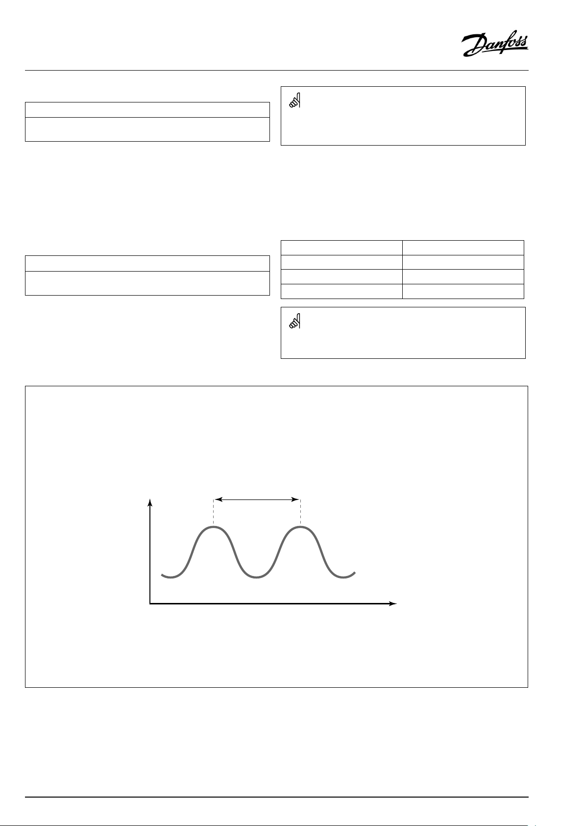
OperatingGuideECLComfort310,applicationA390
MENU>Settings>Controlparameters
Nz(neutralzone)
Whentheactualflowtemperatureiswithintheneutralzone,thecontroller
doesnotactivatethemotorizedcontrolvalve.
SeeAppendix“ParameterIDoverview”
Settheacceptableflowtemperaturedeviation.
Settheneutralzonetoahighvalueifyoucanacceptahigh
variationinflowtemperature.
MENU>Settings>Controlparameters
Min.act.time(min.activationtimegearmotor)
Themin.pulseperiodof20ms(milliseconds)foractivationofthegear
motor.
SeeAppendix“ParameterIDoverview”
1x187
Theneutralzoneissymmetricalaroundthedesiredflowtemperature
value,i.e.halfthevalueisaboveandhalfthevalueisbelowthis
temperature.
SettingexampleValuex20ms
1x189
240ms
10200ms
501000ms
Thesettingshouldbekeptashighasacceptabletoincreasethe
lifetimeoftheactuator(gearmotor).
IfyouwanttotunethePIregulationprecisely,youcanusethefollowingmethod:
•Setthe‘Tn’(integrationtimeconstant)toitsmax.value(999sec.).
•Decreasethevalueforthe‘Xp’(proportionalband)untilthesystemstartshunting(i.e.getsunstable)withaconstantamplitude(it
mightbenecessarytoforcethesystembysettinganextremelowvalue).
•Findthecriticaltimeperiodonthetemperaturerecorderoruseastopwatch.
Temp.
Criticaltimeperiod
Time
Thiscriticaltimeperiodwillbecharacteristicforthesystem,andyoucanevaluatethesettingsfromthiscriticalperiod.
‘Tn’=
0.85xcriticaltimeperiod
‘Xp’=
2.2xproportionalbandvalueinthecriticaltimeperiod
Iftheregulationseemstobetooslow,youcandecreasetheproportionalbandvalueby10%.Makesurethereisaconsumption
whenyousettheparameters.
92|©Danfoss|2021.06
AQ128686479024en-010601
Page 93

OperatingGuideECLComfort310,applicationA390
5.10Application
Thesection"Application"describesspecificapplicationrelated
issues.
Someoftheparameterdescriptionsareuniversalfordifferent
applicationkeys.
ParametersindicatedwithanIDno.like"1x607"meanauniversal
parameter.
xstandsforcircuit/parametergroup.
MENU>Settings>Application
ECAaddr.(ECAaddress,choiceofRemoteControlUnit)
Decidestheroomtemperaturesignaltransferandcommunicationwiththe
RemoteControlUnit.
SeeAppendix“ParameterIDoverview”
OFF:
NoRemoteControlUnit.Onlyroomtemperaturesensor,
ifany.
A:
B:
RemoteControlUnitECA30/31withaddressA.
RemoteControlUnitECA30/31withaddressB.
1x010
TheRemoteControlUnitmustbesetaccordingly(AorB).
AQ128686479024en-010601
©Danfoss|2021.06|93
Page 94
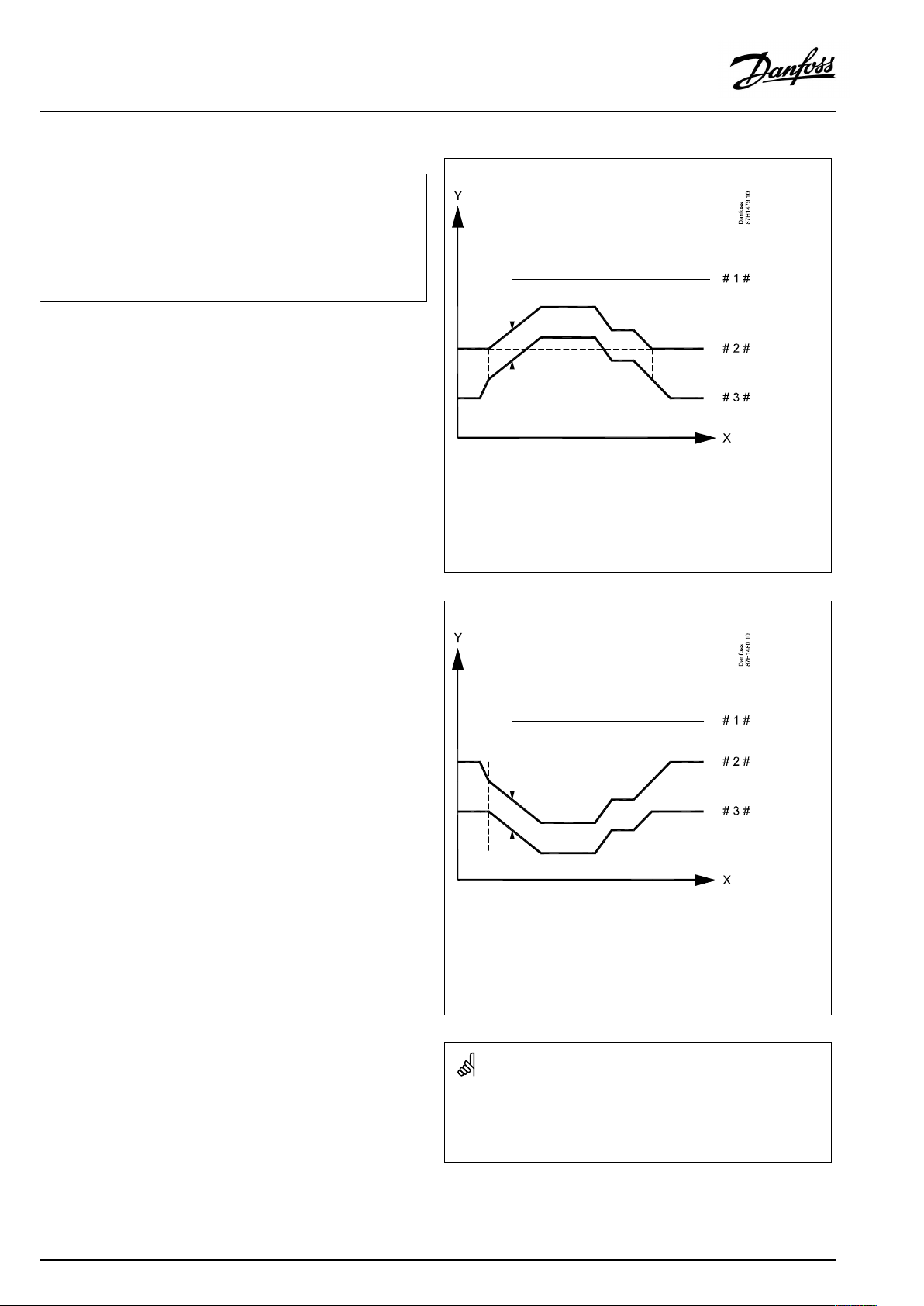
OperatingGuideECLComfort310,applicationA390
MENU>Settings>Application
Demandoffset
Thedesiredflowtemperatureinthemastercircuitcanbeinfluencedbythe
demandforadesiredflowtemperatureinanothercontroller(slave)or
anothercircuit.
The‘Demandoffset’cancompensateforheatingorcoolinglossesbetween
masterandslavecontrolledsystems.
Circuit1isthemastercircuitinmostapplications.
SeeAppendix“ParameterIDoverview”
1x017
Heatingapplication
*
**
OFF:
Value:
heatingapplications:OFF/1...20K
coolingapplications:-20...-1K/OFF
heatingapplications:OFF
coolingapplications:OFF
Thedesiredflowtemperatureisnotinfluencedbythe
demandofanyothercontroller(slave)orcircuit.
Thedesiredflowtemperatureisincreased(heating)or
decreased(cooling)bythesetvaluein‘Demandoffset’ .
X
Y
#1#
#2#
#3#
Coolingapplication
=
Time
=
Desiredflowtemperatures
=
Demandoffset
=
Desiredflowtemperature,master
=
Desiredflowtemperature,slave
94|©Danfoss|2021.06
=
X
Y
#1#
#2#
#3#
Heatingapplications:
Whensetting"Demandoffset"toavalue,thereturntemperature
limitationwillreactaccordingtothehighestheating/DHWlimitation
value.
Time
=
Desiredflowtemperatures
=
Demandoffset
=
Desiredflowtemperature,slave
=
Desiredflowtemperature,master
AQ128686479024en-010601
Page 95

OperatingGuideECLComfort310,applicationA390
MENU>Settings>Application
Whensetting"Demandoffset"toavalue,thereturntemperature
limitationwillreactaccordingtothehighestlimitationvalue(Heating
/DHW).
Pexercise(pumpexercise)
Exercisesthepumptoavoidblockinginperiodswithoutheating/cooling
demand.
SeeAppendix“ParameterIDoverview”
OFF:
ON:
Thepumpexerciseisnotactive.
ThepumpisswitchedONfor1minuteeverythirddayat
noon(12:14hours).
MENU>Settings>Application
Mexercise(valveexercise)
Exercisesthevalvetoavoidblockinginperiodswithoutheating/cooling
demand.
SeeAppendix“ParameterIDoverview”
OFF:
ON:
Thevalveexerciseisnotactive.
Thevalveopensfor7minutesandclosesfor7minutes
everythirddayatnoon(12:00hours).
1x022
1x023
MENU>Settings>Application
Ppost-run
Heatingapplications:
ThecirculationpumpintheheatingcircuitcanbeONforanumberof
minutes(m)afterheatingstop.Heatingstopiswhenthedesiredflow
temperaturegetslowerthanthesettingin'PheatT'(IDno.1x078).
Coolingapplications:
ThecirculationpumpinthecoolingcircuitcanbeONforanumberof
minutes(m)aftercoolingstop.Coolingstopiswhenthedesiredflow
temperaturegetshigherthanthesettingin'PcoolT'(IDno.1x070).
ThisPpost-runfunctioncanutilizetheremainingenergyinforexamplea
heatexchanger.
SeeAppendix“ParameterIDoverview”
0:
Thecirculationpumpstopsimmediatelyafterheating
orcoolingstop.
Value:
ThecirculationpumpisONforthesettimeafterheating
orcoolingstop.
AQ128686479024en-010601
1x040
©Danfoss|2021.06|95
Page 96

OperatingGuideECLComfort310,applicationA390
MENU>Settings>Application
DHWPpost-run(DHWpump,post-run)
SettheDHWpumppost-runtime(minutes).TheDHWpumpcancontinue
tobeswitchedONaftertheDHWheatingprocedureinordertoutilizethe
remainingheatintheheatexchanger/boiler.
SeeAppendix“ParameterIDoverview”
Value:
Setthenumberofminutesforthepost-run.
MENU>Settings>Application
Char.Ppost-run(DHWchargingpump,post-run)
SettheDHWchargingpumppost-runtime(minutes).TheDHWcharging
pumpcancontinuetobeswitchedONaftertheDHWheatingprocedurein
ordertoutilizetheremainingheatintheheatexchanger.
SeeAppendix“ParameterIDoverview”
Value:
Setthenumberofminutesforthepost-run.
MENU>Settings>Application
1x041
1x042
Max.DHWtime
SetthemaxDHWheatingtime(minutes).WhenDHWheatingisactiveand
theset'Max.DHWtime'expires,DHWheatingisdeactivated.
1x044
SeeAppendix“ParameterIDoverview”
OFF:
IftheDHWtemperatureislowerthantheDHWcharging
cut-intemperature,theDHWchargingremainsactive
forunlimitedperiodoftime.IftheDHWtemperatureis
higherthantheDHWchargingcut-intemperature,the
chargingisdeactivatedafter35minutes.
Value:
TheDHWheating/chargingisdeactivatedwhentheset
'Max.DHWtime'(inminutes)expires.
MENU>Settings>Application
DHWdeact.time(DHWdeactivationtime)
Setthetime(minutes)thatmustelapseafteraDHWheatingperiodbeforea
newDHWheatingperiodcanbestarted.
1x045
SeeAppendix“ParameterIDoverview”
Value:WhentheDHWheating/chargingtimehasreachedits
maximum,DHWcanonlybeheated/chargedagain
afterthesetdeactivationtime(inminutes)hasexpired.
96|©Danfoss|2021.06
AQ128686479024en-010601
Page 97

OperatingGuideECLComfort310,applicationA390
MENU>Settings>Application
Pdemand
Thecirculationpumpinthemastercircuitcanbecontrolledinrelationto
themastercircuit'sdemandorslavecircuit'sdemand.
SeeAppendix“ParameterIDoverview”
Heatingapplications:
OFF:
ThecirculationpumpisONwhenthedesiredflow
temperatureintheheatingcircuitishigherthanthe
valuesetin'PheatT'.
ON:
ThecirculationpumpisONwhenthedesiredflow
temperaturefromslavesishigherthanthevaluesetin
'PheatT'.
Coolingapplications:
OFF:
ThecirculationpumpisONwhenthedesiredflow
temperatureinthecoolingcircuitislowerthanthevalue
setin'PcoolT'.
ON:
ThecirculationpumpisONwhenthedesiredflow
temperaturefromslavesislowerthanthevaluesetin
'PcoolT'.
MENU>Settings>Application
1x050
Thecirculationpumpisalwayscontrolledaccordingtofrostprotection
conditions.
Ch.-o.valve/P(changeovervalve/pump)
ChoosewhethertheDHWheatingcontrolisbasedonachangeovervalve
orapump.
SeeAppendix“ParameterIDoverview”
OFF:
ON:
Changeovervalve
Pump
MENU>Settings>Application
DHWpriority(closedvalve/normaloperation)
Theheatingcircuitcanbeclosedwhenthecontrolleractsasslaveandwhen
DHWheating/chargingisactiveinthemaster.
SeeAppendix“ParameterIDoverview”
OFF:
Theflowtemperaturecontrolremainsunchanged
duringactiveDHWheating/charginginthemaster
controller.
ON:
Thevalveintheheatingcircuitisclosed*duringactive
DHWheating/charginginthemastercontroller.
*Thedesiredflowtemperatureissettothevaluesetin
‘Frostpr.T’
1x051
Whenthechangeovervalveischosen,pumpP1isONatheatingas
wellasatDHWheatingdemand.
Whenthepumpischosen,pumpP1isONatheatingandOFFatDHW
heatingdemand.
Aparalleloption(heatingandDHWheatinginparallel)exists,based
onthesetting‘Paralleloperation’ .
1x052
Thissettingmustbeconsideredifthiscontrollerisaslave.
AQ128686479024en-010601
©Danfoss|2021.06|97
Page 98

OperatingGuideECLComfort310,applicationA390
MENU>Settings>Application
Tank,sec./prim.(Tanksecondarilyorprimarily
connected)
ChoosewhethertheheatingoftheDHWtankisdependentontheflow
temperatureatS3.
SeeAppendix“ParameterIDoverview”
OFF:
TheDHWtankisplacedonthesecondarysideofthe
heatexchangerandtheS3temperaturedetermines
theDHWheating.
ON:
TheDHWtankisplacedontheprimarysideoftheheat
exchangerandtheS3temperaturehasnoinfluence
ontheDHWheating.
MENU>Settings>Application
Cont.Tcontrol
ThedesiredDHWheating/chargingtemperaturecanbeloweredwhenthe
DHWheating/chargingprocedurehaselapsed.
SeeAppendix“ParameterIDoverview”
OFF:
Thedesiredheating/chargingtemperatureislowered
to10°C.Typically,theDHWiscirculatedthroughthe
DHWtank.
ON:
Thedesiredheating/chargingtemperatureislowered
tothedesiredDHWtemperature.Typically,theDHW
iscirculatedthroughtheheatexchangerinorderto
compensatefortheheatlossintheDHWcirculation
pipe.
1x053
1x054
MENU>Settings>Application
Circ.Ppriority
ChoosewhethertheDHWcirculationpumpshouldbeONduringDHW
heating.
SeeAppendix“ParameterIDoverview”
OFF:
TheDHWcirculationpumpisswitchedOFFduringDHW
heating.
ON:
TheDHWcirculationpumpisnotswitchedOFFduring
DHWheating.
1x055
Whenthe'Circ.Ppriority'issettoOFF ,theschedulefortheDHW
circulationpumpisoverruled.
98|©Danfoss|2021.06
AQ128686479024en-010601
Page 99

OperatingGuideECLComfort310,applicationA390
MENU>Settings>Application
Pchargedelay(Chargingpump,delayedstart)
ConditionsforswitchingtheDHWheating/chargingpumpONatDHW
heating/chargingdemand.
Correctsettingcanavoiddischarging.
SeeAppendix“ParameterIDoverview”
OFF:
DHWheating/chargingpumpisswitchedONwhen
DHWheating/chargingtemperatureisOK.
0:
Value:
DHWheating/chargingpumpisswitchedON.
DHWheating/chargingpumpisswitchedONafterthe
setnumberofminutes.
MENU>Settings>Application
PcoolT(coolingdemand)
Whenthedesiredflowtemperatureisbelowthesettemperaturein‘PcoolT’ ,
thecontrollerautomaticallyswitchesONthecirculationpump.
SeeAppendix“ParameterIDoverview”
Value:
ThecirculationpumpisswitchedONwhenthedesired
flowtemperatureisbelowthesetvalue.
1x059
Whenthesetting"OFF"isselected,thetemperaturesensorforDHW
heating/chargingmustbeplacedintheheat-exchanger.
1x070
Thevalveisfullyclosedaslongasthepumpisnotswitchedon.
MENU>Settings>Application
Circ.PfrostT
SettheoutdoortemperaturevalueatwhichtheDHWcirculationpumpisto
beactivetoprotecttheDHWcircuitagainstfrost.
SeeAppendix“ParameterIDoverview”
OFF:
Value:
TheDHWcirculationpumpisnotactive.
TheDHWcirculationpumpisactivewhentheoutdoor
temperatureislowerthanthesetvalue.
MENU>Settings>Application
PfrostT(circulationpump,frostprotectiontemp.)
Frostprotection,basedontheoutdoortemperature.
Whentheoutdoortemperaturegetsbelowthesettemperaturevaluein‘P
frostT’ ,thecontrollerautomaticallyswitchesONthecirculationpump(for
exampleP1orX3)toprotectthesystem.
SeeAppendix“ParameterIDoverview”
OFF:
Value:
Nofrostprotection.
CirculationpumpisONwhentheoutdoortemperature
isbelowthesetvalue.
1x076
1x077
Undernormalconditions,yoursystemisnotfrostprotectedifyour
settingisbelow0°CorOFF.
Forwater-basedsystems,asettingof2°Cisrecommended.
Iftheoutdoortemperaturesensorisnotconnectedandthefactory
settinghasnotbeenchangedto'OFF' ,thecirculationpumpisalways
ON.
AQ128686479024en-010601
©Danfoss|2021.06|99
Page 100

OperatingGuideECLComfort310,applicationA390
MENU>Settings>Application
PheatT(heatdemand)
Whenthedesiredflowtemperatureisabovethesettemperaturein‘PheatT’ ,
thecontrollerautomaticallyswitchesONthecirculationpump.
1x078
SeeAppendix“ParameterIDoverview”
Value:ThecirculationpumpisswitchedONwhenthedesired
flowtemperatureisabovethesetvalue.
MENU>Settings>Application
StandbyT
Setthedesiredflowtemperatureforthecontrollerwhenitisinstandby
mode.
1x092
SeeAppendix“ParameterIDoverview”
Value:
Desiredflowtemperatureatstandby.
MENU>Settings>Application
Frostpr .T(frostprotectiontemp.)
SetthedesiredflowtemperatureattheflowtemperaturesensorS3to
protectthesystemagainstfrost(atheatingcut-out,totalstopetc.).
Whentheflowtemperaturegetslowerthanthesetting,themotorized
controlvalveopensgradually.
1x093
Thevalveisfullyclosedaslongasthepumpisnotswitchedon.
Thefrostprotectiontemperaturecanalsobesetinyourfavorite
displaywhenthemodeselectorisinfrostprotectionmode.
SeeAppendix“ParameterIDoverview”
100|©Danfoss|2021.06
AQ128686479024en-010601
 Loading...