

Page 1
OperatingGuide
ECLComfort310,applicationA367
1.0TableofContents
1.0TableofContents...............................................1
1.1Importantsafetyandproductinformation.....................2
2.0Installation........................................................5
2.1Beforeyoustart.....................................................5
2.2Identifyingthesystemtype......................................10
2.3Mounting...........................................................11
2.4Placingthetemperaturesensors................................15
2.5Electricalconnections.............................................17
2.6InsertingtheECLApplicationKey..............................26
2.7Checklist............................................................33
2.8Navigation,ECLApplicationKeyA367.........................34
3.0Dailyuse.........................................................37
3.1Howtonavigate...................................................37
3.2Understandingthecontrollerdisplay..........................38
3.3Ageneraloverview:Whatdothesymbolsmean?...........42
3.4Monitoringtemperaturesandsystem
components........................................................43
3.5Influenceoverview................................................44
3.6Manualcontrol.....................................................45
3.7Schedule............................................................46
4.0Settingsoverview............................................47
5.0Settings...........................................................50
5.1IntroductiontoSettings..........................................50
5.2Flowtemperature..................................................51
5.3Roomlimit..........................................................55
5.4Returnlimit.........................................................57
5.5Flow/powerlimit.................................................64
5.6Optimization........................................................69
5.7Controlparameters................................................76
5.8Application.........................................................80
5.9Heatcut-out........................................................90
5.10Tanktemperature..................................................93
5.11Alarm................................................................98
5.12Alarmoverview..................................................101
5.13Anti-bacteria......................................................102
6.0Commoncontrollersettings............................104
6.1Introductionto‘Commoncontrollersettings’..............104
6.2Time&Date.......................................................105
6.3Holiday............................................................106
6.4Inputoverview...................................................108
6.5Log.................................................................109
6.6Outputoverride..................................................110
6.7Keyfunctions.....................................................111
6.8System.............................................................113
7.0Miscellaneous................................................120
7.1ECA30/31setupprocedures.................................120
7.2Overridefunction................................................128
7.3Severalcontrollersinthesamesystem......................131
7.4Frequentlyaskedquestions....................................134
7.5Definitions........................................................137
7.6Type(ID6001),overview.......................................141
7.7Automatic/manualupdateoffirmware.....................142
7.8ParameterIDoverview..........................................143
©Danfoss|2021.03AQ005186455839en-010401|1
Page 2
OperatingGuideECLComfort310,applicationA367
1.1Importantsafetyandproductinformation
1.1.1Importantsafetyandproductinformation
ThisInstallationGuideisassociatedwithECLApplicationKeyA367
(ordercodeno.087H3813).
ThefunctionscanberealizedinECLComfort310whichincludes
M-bus,ModbusandEthernet(Internet)communication.
TheapplicationsA367.1andA367.2complywithECLComfort
controller310asofsoftwareversion1.11(visibleatstart-upofthe
controllerandin‘Commoncontrollersettings’in‘System’).
AdditionaldocumentationforECLComfort310,modulesand
accessoriesisavailableonhttp://heating.danfoss.com/.
Applicationkeysmightbereleasedbeforealldisplaytextsare
translated.InthiscasethetextisinEnglish.
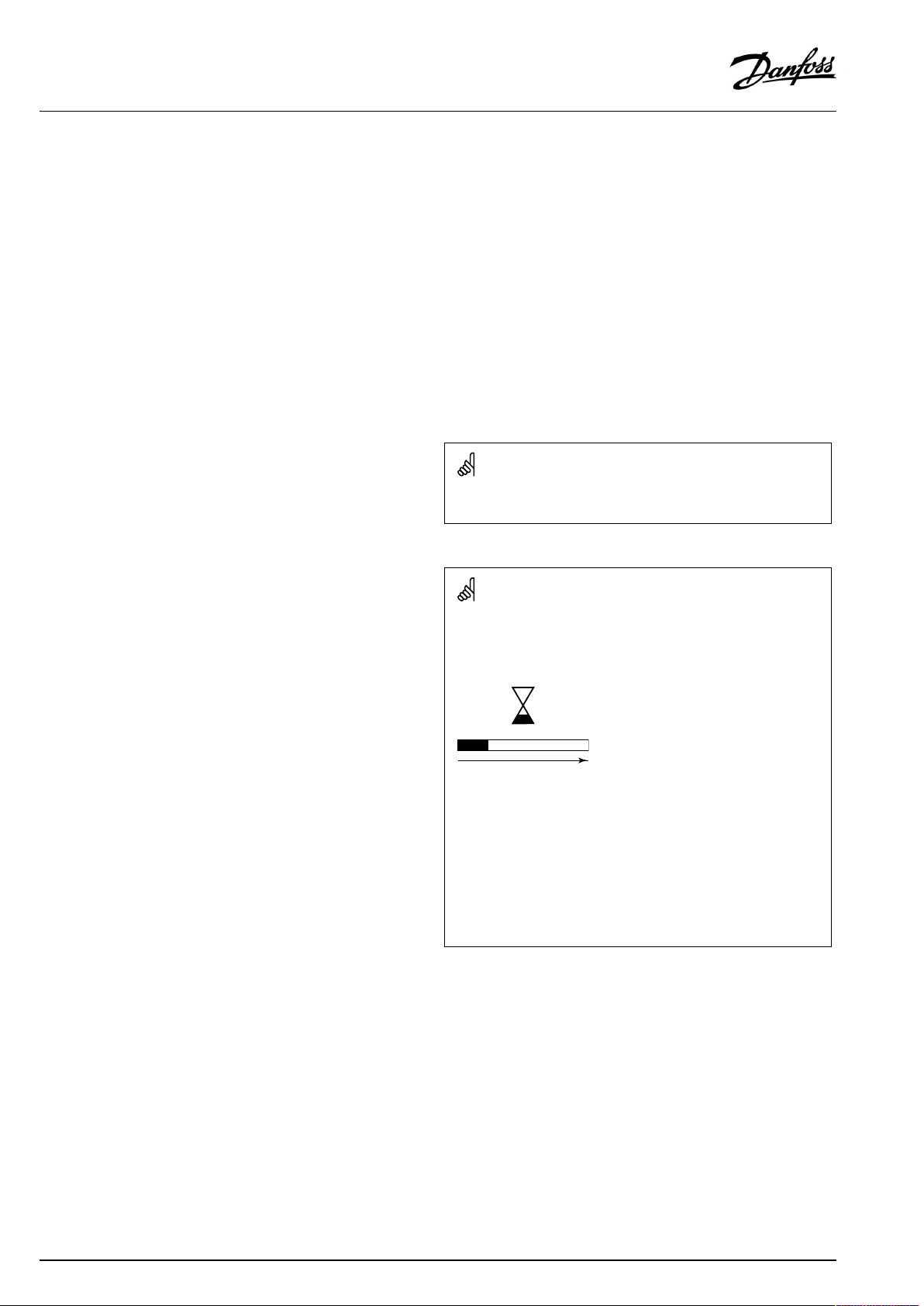
Automaticupdateofcontrollersoftware(firmware):
Thesoftwareofthecontrollerisupdatedautomaticallywhenthekey
isinserted(asofcontrollerversion1.11(ECL210/310)andversion
1.58(ECL296)).Thefollowinganimationwillbeshownwhenthe
softwareisbeingupdated:
Progressbar
Duringupdate:
•DonotremovetheKEY
Ifthekeyisremovedbeforethehour-glassisshown,youhave
tostartafresh.
•Donotdisconnectthepower
Ifthepowerisinterruptedwhenthehour-glassisshown,the
controllerwillnotwork.
•Manualupdateofcontrollersoftware(firmware):
Seethesection"Automatic/manualupdateoffirmware"
2|©Danfoss|2021.03
AQ005186455839en-010401
Page 3
OperatingGuideECLComfort310,applicationA367
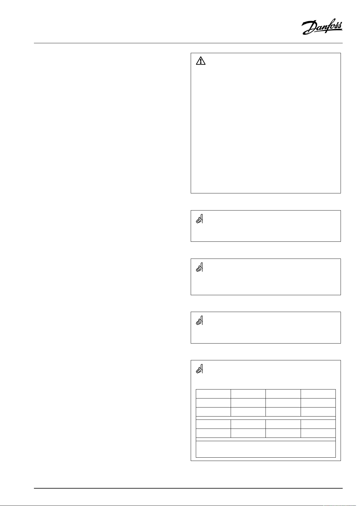
SafetyNote
Toavoidinjuryofpersonsanddamagestothedevice,itisabsolutely
necessarytoreadandobservetheseinstructionscarefully.
Necessaryassembly,start-up,andmaintenanceworkmustbe
performedbyqualifiedandauthorizedpersonnelonly.
Locallegislationsmustberespected.Thiscomprisesalsocable
dimensionsandtypeofisolation(doubleisolatedat230V).
AfusefortheECLComfortinstallationismax.10Atypically.
TheambienttemperaturerangesforECLComfortinoperationare:
ECLComfort210/310:0-55°C
ECLComfort296:0-45°C.
Exceedingthetemperaturerangecanresultinmalfunctions.
Installationmustbeavoidedifthereisariskforcondensation(dew).
Thewarningsignisusedtoemphasizespecialconditionsthatshould
betakenintoconsideration.
Thissymbolindicatesthatthisparticularpieceofinformationshould
bereadwithspecialattention.
AsthisOperatingGuidecoversseveralsystemtypes,specialsystem
settingswillbemarkedwithasystemtype.Allsystemtypesareshown
inthechapter:'Identifyingyoursystemtype'.
°C(degreesCelsius)isameasuredtemperaturevaluewhereasK
(Kelvin)oftenisusedfortemperaturedifferences.
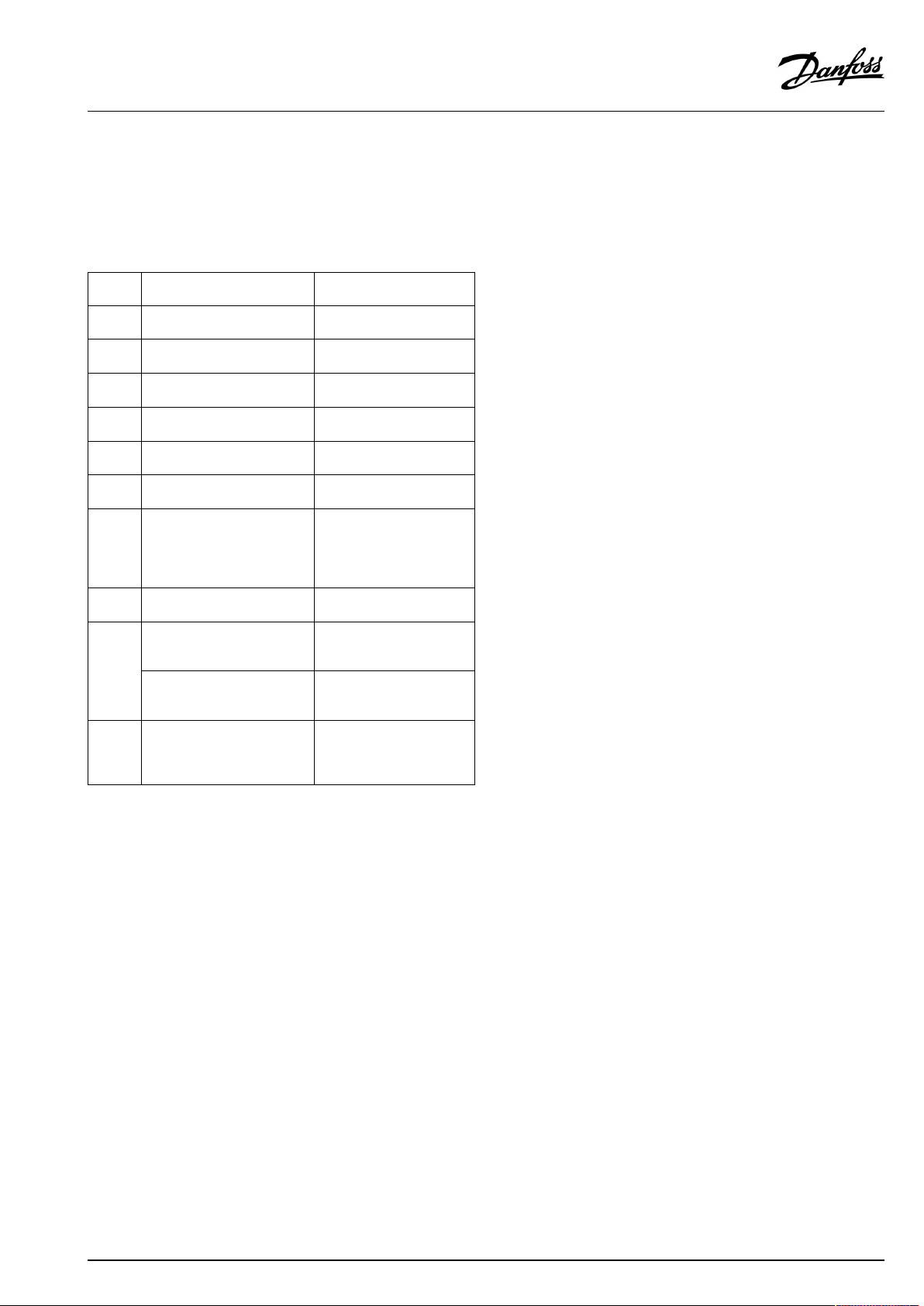
TheIDno.isuniquefortheselectedparameter.
ExampleFirstdigitSeconddigitLastthreedigits
1117411174
-
Circuit1Parameterno.
12174
IfanIDdescriptionismentionedmorethanonce,itmeansthatthere
arespecialsettingsforoneormoresystemtypes.Itwillbemarked
withthesystemtypeinquestion(e.g.12174-A266.9).
1
-
2
Circuit2Parameterno.
AQ005186455839en-010401
174
©Danfoss|2021.03|3
Page 4
OperatingGuideECLComfort310,applicationA367
ParametersindicatedwithanIDno.like"1x607"meanauniversal
parameter.
xstandsforcircuit/parametergroup.
DisposalNote
Thissymbolontheproductindicatesthatitmaynot
bedisposedofashouseholdwaste.
Itmustbehandedovertotheapplicabletake-back
schemefortherecyclingofelectricalandelectronic
equipment.
•Disposeoftheproductthroughchannelsprovided
forthispurpose.
•Complywithalllocalandcurrentlyapplicablelaws
andregulations.
4|©Danfoss|2021.03
AQ005186455839en-010401
Page 5
OperatingGuideECLComfort310,applicationA367
2.0Installation
2.1Beforeyoustart
Thetwoapplications,A367.1andA367.2arealmostidentical.
However,A367.2hassomeextrafunctionswhicharedescribed
separately.
Theapplicationsareveryflexible.Thesearethebasicprinciples:
Heating(circuit1):
Typically,theflowtemperatureisadjustedaccordingtoyour
requirements.TheflowtemperaturesensorS3isthemost
importantsensor.ThedesiredflowtemperatureatS3iscalculated
intheECLcontroller,basedontheoutdoortemperature(S1).
Thelowertheoutdoortemperature,thehigherthedesiredflow
temperature.Bymeansofaweekschedule(upto3‘Comfort’
periods/day),theheatingcircuit1canbein‘Comfort’or
‘Saving’mode(twodifferenttemperaturevaluesfordesiredroom
temperature).
ThemotorizedcontrolvalveM1isopenedgraduallywhenthe
flowtemperatureislowerthanthedesiredflowtemperatureand
viceversa.
Thereturntemperature(S5)tothedistrictheatingsupplyshould
notbetoohigh.Ifso,thedesiredflowtemperaturecanbeadjusted
(typicallytoalowervalue),thusresultinginagradualclosingofthe
motorizedcontrolvalve.
Inboiler-basedheatingsupplythereturntemperatureshouldnot
betoolow(sameadjustmentprocedureasabove).
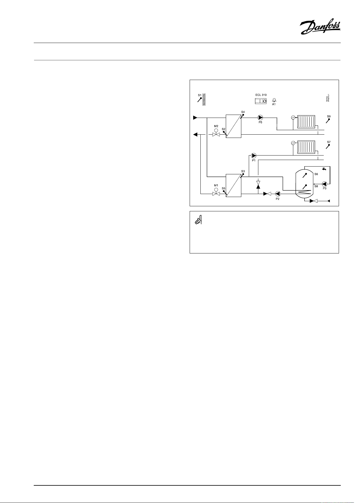
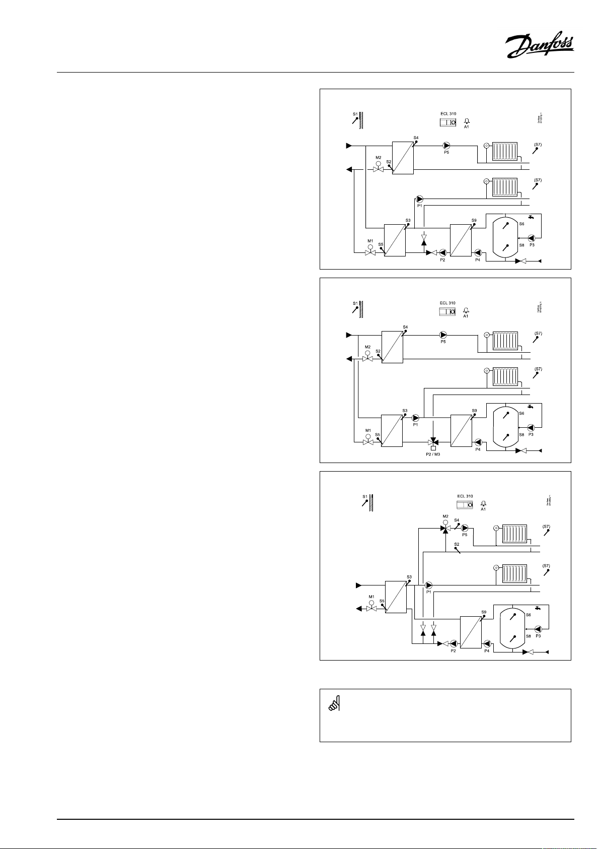
TypicalA367application:
Theshowndiagramisafundamentalandsimplifiedexampleanddoes
notcontainallcomponentsthatarenecessaryinasystem.
AllnamedcomponentsareconnectedtotheECLComfortcontroller.
Furthermore,thereturntemperaturelimitationcandepend
ontheoutdoortemperature.Typically,thelowertheoutdoor
temperature,thehighertheacceptedreturntemperature.
Ifthemeasuredroomtemperature(S7)doesnotequalthedesired
roomtemperature,thedesiredflowtemperaturecanbeadjusted.
Thecirculationpump(P1)isONatheatdemandoratfrost
protection.Thecirculationpump(P1)isswitchedOFFwhen
heatingtheDHW.Ifthesystemhasachangeovervalve(P2/M3)
betweentheheatingandDHWcircuit,thecirculationpump(P1)
isONwhenheatingtheDHW.
TheheatingcanbeswitchedOFFwhentheoutdoortemperatureis
higherthanaselectablevalue.
Listofcomponents:
S1
Outdoortemperaturesensor
S2Returntemperaturesensor,circuit2
S3
Flowtemperaturesensor,circuit1
S4
Flowtemperaturesensor,circuit2
S5Returntemperaturesensor,circuit1
S6
DHWtanktemperaturesensor,upper
S7Roomtemperaturesensor,circuit1
S8
DHWtanktemperaturesensor,lower
S9Roomtemperaturesensor,circuit2
P1
Circulationpump,heating,circuit1
P2
DHWheatingpump,circuit3
P3
DHWcirculationpump,circuit3
P5
Circulationpump,heating,circuit2
M1
Motorizedcontrolvalve,circuit1andDHW
M2
Motorizedcontrolvalve,circuit2
(M3)
(Changeovervalve,circuit1,heating/DHW)
R6
Relayoutput,alarm
AQ005186455839en-010401
©Danfoss|2021.03|5
Page 6
OperatingGuideECLComfort310,applicationA367
Heating(circuit2):
Thiscircuitworksaftersameprinciplesascircuit1.
TheflowtemperaturesensorS4isthemostimportantsensor.
Bymeansofaweekschedule(upto3‘Comfort’periods/day),the
heatingcircuit2canbein‘Comfort’or‘Saving’mode(twodifferent
temperaturevaluesfordesiredroomtemperature).Themotorized
controlvalveM2controlsthecircuit.
Thereturntemperature(S2)enableslimitationasdescribed
previously.
IfthemeasuredroomtemperatureS9(S7inA367.2)doesnot
equalthedesiredroomtemperature,thedesiredflowtemperature
canbeadjusted.
Thecirculationpump(P5)isONatheatdemandoratfrost
protection.
TheheatingcanbeswitchedOFFwhentheoutdoortemperatureis
higherthanaselectablevalue.
Heatingcircuit2canbeconnectedafterheatingcircuit1.Ifso,the
desiredflowtemperatureatS3canbeinfluencedbythedesired
flowtemperatureatS4.
A367.2heatingcircuit1and2:
Theheatingcircuit1and2canusethesameroomtemperature
sensor(S7).However,eachheatingcircuitcanhaveanECA30,
RemoteControlUnit,inordertohaveseparateroomtemperature
signals.Anothersolution:UseS7foroneoftheheatingcircuitsand
ECA30fortheotherheatingcircuit.
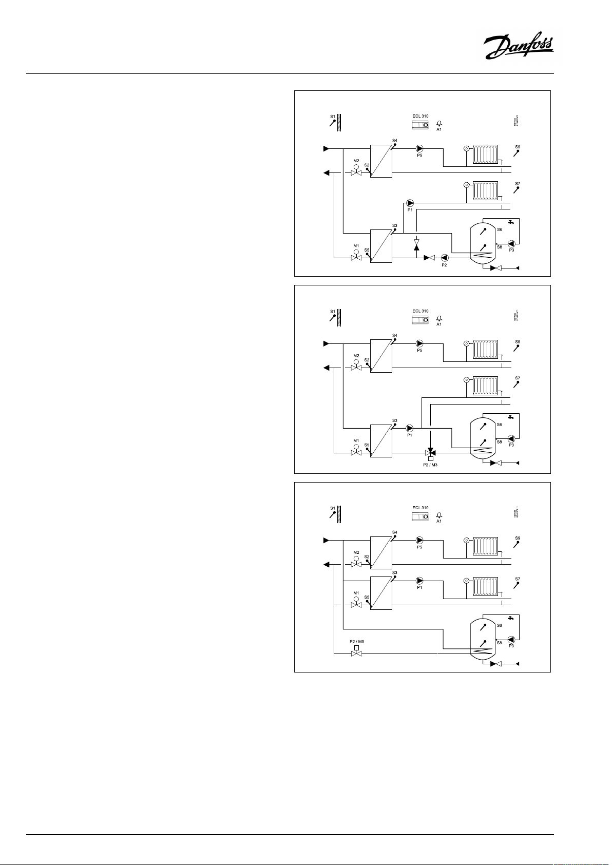
A367.1examplea:
A367.1exampleb:
A367.1examplec:
6|©Danfoss|2021.03
AQ005186455839en-010401
Page 7
OperatingGuideECLComfort310,applicationA367
DomesticHotWater(DHW ,circuit3):
Bymeansofaweekschedule(upto3Comfortperiods/day),the
DHWcircuitcanbein‘Comfort’or‘Saving’mode(twodifferent
temperaturevaluesfordesiredDHWtemperature).
A367.1:
IfthemeasuredDHWtemperature(S6)islowerthanthedesired
DHWtemperature,theheatingcirculationpump(P1)isswitched
OFFandtheDHWheatingpump(P2)isswitchedON.The
motorizedcontrolvalve(M1)iscontrolledinordertomaintainthe
DHWheatingtemperatureatS3.
TheDHWheatingtemperatureistypically10-15degreeshigher
thanthedesiredDHWtemperature.
DHWtankwith1temperaturesensor:
WhenthemeasuredDHWtemperature(S6)getshigherthanthe
desiredDHWtemperature,theDHWheatingpump(P2)isswitched
OFF.Apost-runtimecanbeset.Themotorizedcontrolvalve(M1)
willhereaftermaintainthedesiredflowtemperatureintheheating
circuit.
DHWtankwith2temperaturesensors:
WhenthemeasuredDHWtemperature(S6)getshigherthanthe
desiredDHWtemperatureandthelowertemperature(atS8)gets
higherthanthecut-outtemperature,theDHWheatingpump(P2)
isswitchedOFF.Apost-runtimecanbeset.Themotorizedcontrol
valve(M1)willhereaftermaintainthedesiredflowtemperaturein
theheatingcircuit.
A367.1exampled:
A367.1examplee:
AQ005186455839en-010401
©Danfoss|2021.03|7
Page 8
OperatingGuideECLComfort310,applicationA367
A367.2:
IfthemeasuredDHWtemperature(S6)islowerthanthedesired
DHWtemperature,theheatingcirculationpump(P1)isswitched
OFFandtheDHWpump(P2)isswitchedON.Themotorizedcontrol
valve(M1)iscontrolledinordertomaintaintheDHWheating
temperatureatS3.
TheDHWheatingtemperatureisdeterminedbythedesiredDHW
chargingtemperatureatS9.WhentheDHWheatingtemperature
isreached,(ormax.3minutesafterDHWheatingdemand),the
DHWchargingpumpP4isswitchedON.
TheDHWchargingtemperatureistypically5-10degreeshigher
thanthedesiredDHWtemperature.
IftheDHWchargingtemperatureatS9cannotbereached,the
ECLcontrollergraduallyincreasesthedesiredDHWheating
temperatureatS3inordertoobtainthechargingtemperature.
Amax.valuecanbeset.
DHWtankwith1temperaturesensor:
WhenthemeasuredDHWtemperature(S6)getshigherthanthe
desiredDHWtemperature,theDHWpump(P2)andDHWcharging
pump(P4)areswitchedOFF .Post-runtimescanbeset.The
motorizedcontrolvalve(M1)willhereaftermaintainthedesired
flowtemperatureintheheatingcircuit.
DHWtankwith2temperaturesensors:
WhenthemeasuredDHWtemperature(S6)getshigherthanthe
desiredDHWtemperatureandthelowertemperature(atS8)gets
higherthanthecut-outtemperature,theDHWpump(P2)and
DHWchargingpump(P4)areswitchedOFF.Post-runtimescanbe
set.Themotorizedcontrolvalve(M1)willhereaftermaintainthe
desiredflowtemperatureintheheatingcircuit.
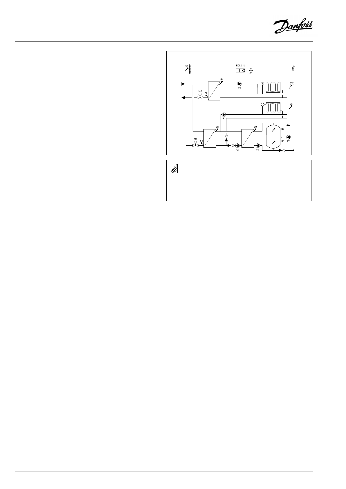
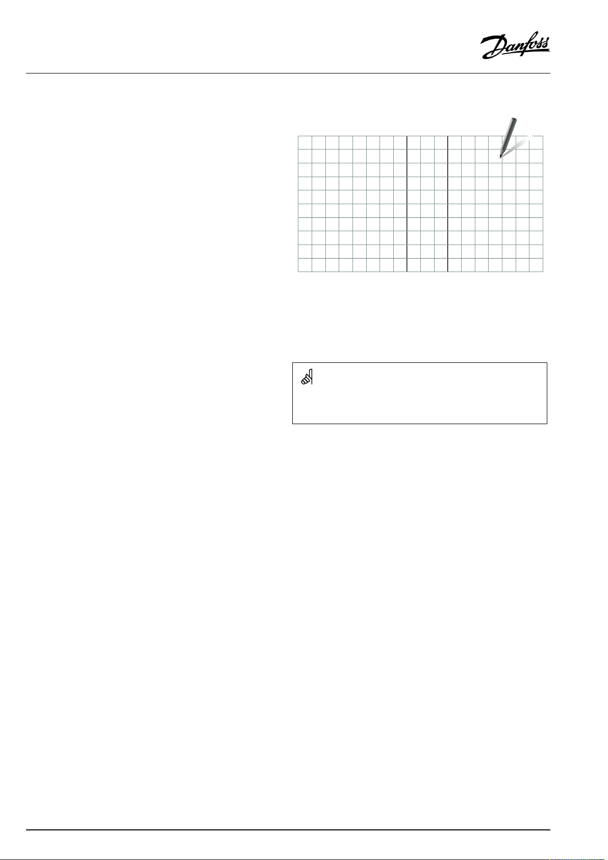
TypicalA367.2application:
Theshowndiagramisafundamentalandsimplifiedexampleanddoes
notcontainallcomponentsthatarenecessaryinasystem.
AllnamedcomponentsareconnectedtotheECLComfortcontroller.
Listofcomponents:
S1
Outdoortemperaturesensor
S2Returntemperaturesensor,circuit2
S3
Flowtemperaturesensor,circuit1
S4
Flowtemperaturesensor,circuit2
S5Returntemperaturesensor,circuit1
S6
DHWtanktemperaturesensor,upper
S7
Roomtemperaturesensor,circuit1/2
S8
DHWtanktemperaturesensor,lower
S9
DHWchargingtemperaturesensor,circuit3
P1
Circulationpump,heating,circuit1
P2
DHWheatingpump,circuit3
P3
DHWcirculationpump,circuit3
P4
DHWchargingpump,circuit3
P5
Circulationpump,heating,circuit2
M1
Motorizedcontrolvalve,circuit1andDHW
M2
Motorizedcontrolvalve,circuit2
(M3)
(Changeovervalve,circuit1,heating/DHW)
R6
Relayoutput,alarm
8|©Danfoss|2021.03
AQ005186455839en-010401
Page 9
OperatingGuideECLComfort310,applicationA367
DHWcircuit,ingeneral:
Iftheinstallationhasachangeovervalve(P2/M3),alsocalled
priority-valve,betweentheheatingandtheDHWcircuits,the
changeovervalveisactivatedatDHWheatingdemand.The
circulationpump(P1)isONwhenheatingtheDHW.
Parallelmodeintwo-pumpapplications:
IftheDHWheatingtemperaturehasavalueclosetothedesired
flowtemperatureintheheatingcircuit,thecirculationpump(P1)in
theheatingcircuitwillnotbeswitchedOFFduringDHWheating.
Thereturntemperature(S5),whentheDHWheatingisactive,can
belimitedtoafixedvalue.
Ananti-bacteriafunctionisavailableforactivationonselected
daysoftheweek.
A367.1only:TheDHWcircuitcanbeconnectedprimarilyandthe
valve‘P2/M3’operatesasON/OFFvalve.
TheDHWcirculationpump(P3)hasaweekscheduleforupto3
ON-periods/day.
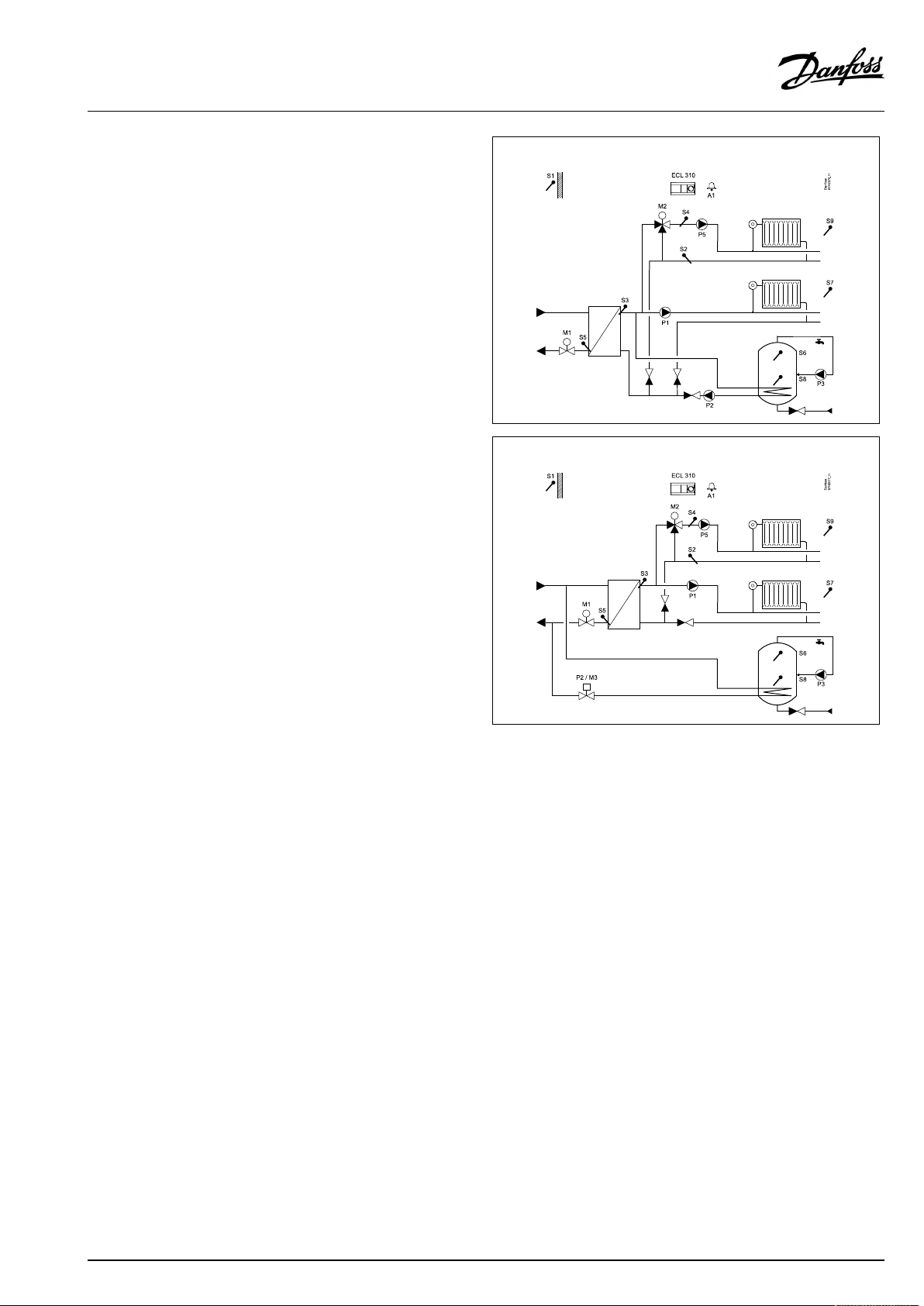
A367.2examplea:
A367.2exampleb:
A367.2examplec:
Thecontrollerispre-programmedwithfactorysettingsthatareshown
inthe‘ParameterIDoverview’appendix.
AQ005186455839en-010401
©Danfoss|2021.03|9
Page 10
OperatingGuideECLComfort310,applicationA367
2.2Identifyingthesystemtype
Sketchyourapplication
TheECLComfortcontrollerseriesisdesignedforawiderange
ofheating,domestichot-water(DHW)andcoolingsystemswith
differentconfigurationsandcapacities.Ifyoursystemdiffers
fromthediagramsshownhere,youmaywanttomakeasketch
ofthesystemabouttobeinstalled.Thismakesiteasiertouse
theOperatingGuide,whichwillguideyoustep-by-stepfrom
installationtofinaladjustmentsbeforetheend-usertakesover.
TheECLComfortcontrollerisauniversalcontrollerthatcanbe
usedforvarioussystems.Basedontheshownstandardsystems,
itispossibletoconfigureadditionalsystems.Inthischapteryou
findthemostfrequentlyusedsystems.Ifyoursystemisnotquite
asshownbelow,findthediagramwhichhasthebestresemblance
withyoursystemandmakeyourowncombinations.
SeetheInstallationGuide(deliveredwiththeapplicationkey)for
applicationtypes/sub-types.
Thecirculationpump(s)inheatingcircuit(s)canbeplacedintheflow
aswellasthereturn.Placethepumpaccordingtothemanufacturer’s
specification.
10|©Danfoss|2021.03
AQ005186455839en-010401
Page 11
OperatingGuideECLComfort310,applicationA367
2.3Mounting
2.3.1MountingtheECLComfortcontroller
SeetheInstallationGuidewhichisdeliveredtogetherwiththe
ECLComfortcontroller.
Foreasyaccess,youshouldmounttheECLComfortcontrollernear
thesystem.
ECLComfort210/296/310canbemounted
•onawall
•onaDINrail(35mm)
ECLComfort296canbemounted
•inapanelcut-out
ECLComfort210canbemountedinanECLComfort310basepart
(forfutureupgrade).
Screws,PGcableglandsandrawlplugsarenotsupplied.
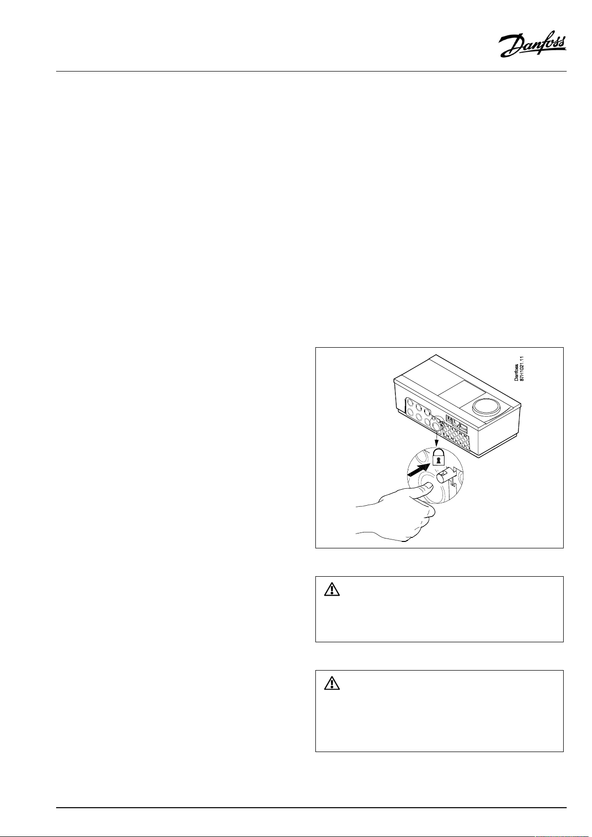
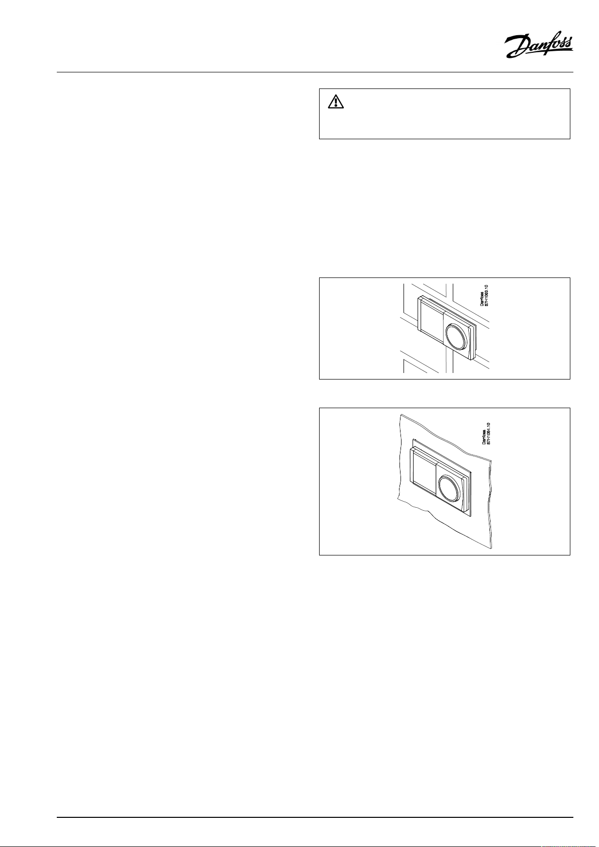
LockingtheECLComfort210/310controller
InordertofastentheECLComfortcontrollertoitsbasepart,secure
thecontrollerwiththelockingpin.
Topreventinjuriestopersonsorthecontroller,thecontrollerhasto
besecurelylockedintothebase.Forthispurpose,pressthelocking
pinintothebaseuntilaclickisheardandthecontrollernolonger
canberemovedfromthebase.
Ifthecontrollerisnotsecurelylockedintothebasepart,thereisarisk
thatthecontrollerduringoperationcanunlockfromthebaseandthe
basewithterminals(andalsothe230Va.c.connections)areexposed.
Topreventinjuriestopersons,alwaysmakesurethatthecontroller
issecurelylockedintoitsbase.Ifthisisnotthecase,thecontroller
shouldnotbeoperated!
AQ005186455839en-010401
©Danfoss|2021.03|11
Page 12
OperatingGuideECLComfort310,applicationA367
Mountingonawall
Mountthebasepartonawallwithasmoothsurface.Establishthe
electricalconnectionsandpositionthecontrollerinthebasepart.
Securethecontrollerwiththelockingpin.
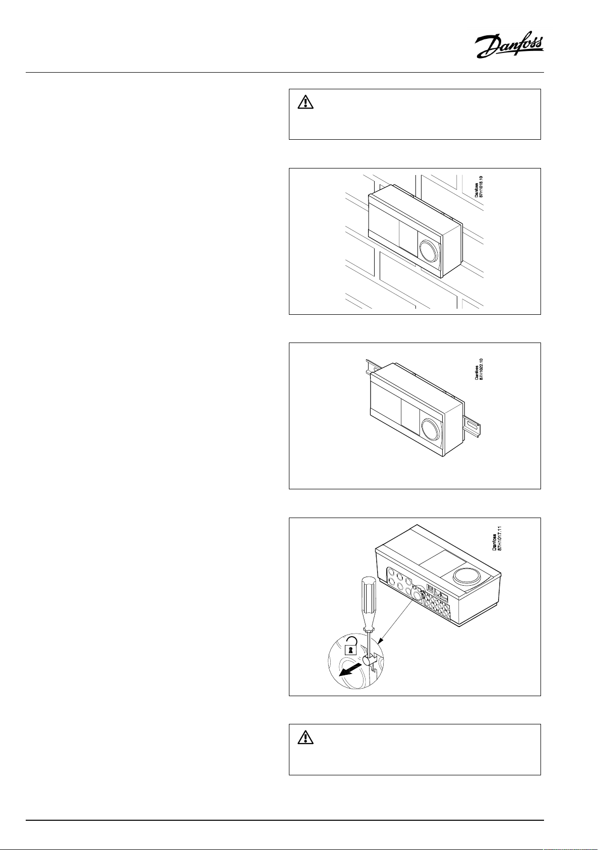
MountingonaDINrail(35mm)
MountthebasepartonaDINrail.Establishtheelectrical
connectionsandpositionthecontrollerinthebasepart.Secure
thecontrollerwiththelockingpin.
Theeasywaytolockthecontrollertoitsbaseorunlockitistousea
screwdriveraslever.
DismountingtheECLComfortcontroller
Inordertoremovethecontrollerfromthebasepart,pulloutthe
lockingpinbymeansofascrewdriver.Thecontrollercannowbe
removedfromthebasepart.
Theeasywaytolockthecontrollertoitsbaseorunlockitistousea
screwdriveraslever.
12|©Danfoss|2021.03
AQ005186455839en-010401
Page 13
OperatingGuideECLComfort310,applicationA367
2.3.2MountingtheRemoteControlUnitsECA30/31
Selectoneofthefollowingmethods:
•Mountingonawall,ECA30/31
•Mountinginapanel,ECA30
Screwsandrawlplugsarenotsupplied.
Mountingonawall
MountthebasepartoftheECA30/31onawallwithasmooth
surface.Establishtheelectricalconnections.PlacetheECA30/
31inthebasepart.
BeforeremovingtheECLComfortcontrollerfromthebasepart,ensure
thatthesupplyvoltageisdisconnected.
Mountinginapanel
MounttheECA30inapanelusingtheECA30framekit(ordercode
no.087H3236).Establishtheelectricalconnections.Securethe
framewiththeclamp.PlacetheECA30inthebasepart.TheECA
30canbeconnectedtoanexternalroomtemperaturesensor.
TheECA31mustnotbemountedinapanelifthehumidity
functionistobeused.
AQ005186455839en-010401
©Danfoss|2021.03|13
Page 14
OperatingGuideECLComfort310,applicationA367
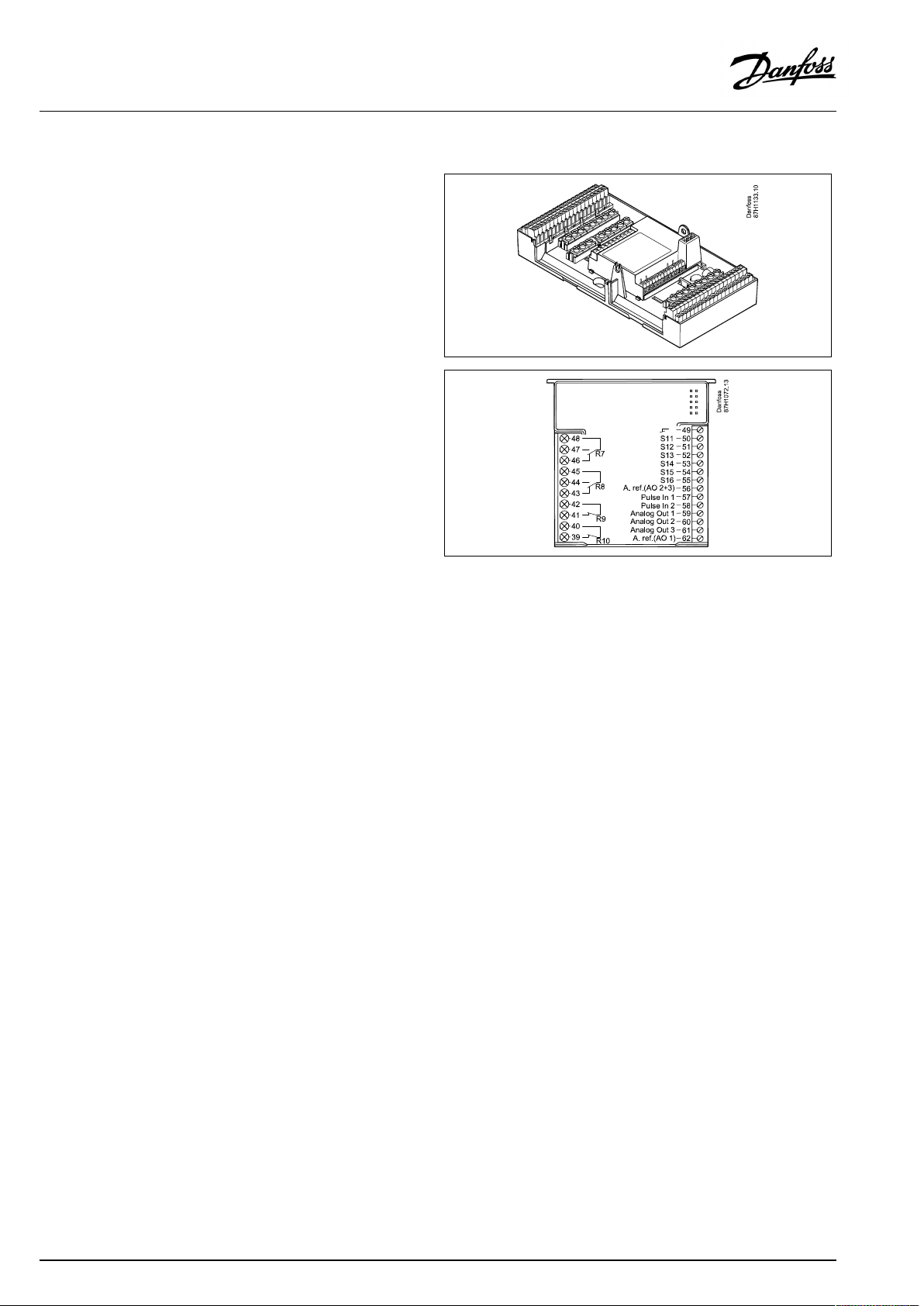
2.3.3MountingtheinternalI/OmoduleECA32
MountingoftheinternalI/OmoduleECA32
TheECA32module(ordercodeno.087H3202)mustbeinserted
intotheECLComfort310/310Bbasepartforadditionalinputand
outputsignalsinrelevantapplications.
TheconnectionbetweentheECLComfort310/310BandECA32
isa10-pole(2x5)connector.Theconnectionisautomatically
establishedwhentheECLComfort310/310Bisplacedonthe
basepart.
14|©Danfoss|2021.03
AQ005186455839en-010401
Page 15
OperatingGuideECLComfort310,applicationA367
2.4Placingthetemperaturesensors
2.4.1Placingthetemperaturesensors
Itisimportantthatthesensorsaremountedinthecorrectposition
inyoursystem.
Thetemperaturesensormentionedbelowaresensorsusedforthe
ECLComfort210/296/310serieswhichnotallwillbeneeded
foryourapplication!
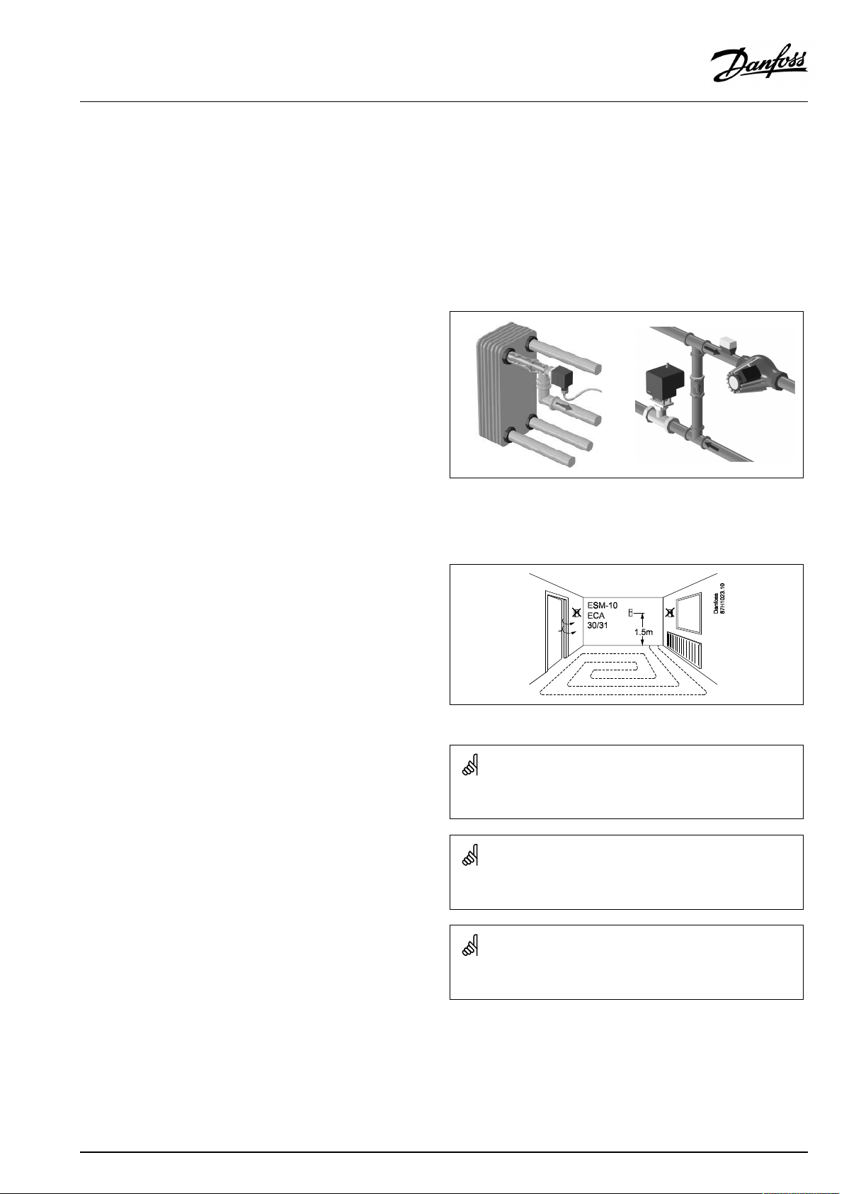
Outdoortemperaturesensor(ESMT)
Theoutdoorsensorshouldbemountedonthatsideofthebuilding
whereitislesslikelytobeexposedtodirectsunshine.Itshouldnot
beplacedclosetodoors,windowsorairoutlets.
Flowtemperaturesensor(ESMU,ESM-11orESMC)
Placethesensormax.15cmfromthemixingpoint.Insystems
withheatexchanger,DanfossrecommendsthattheESMU-typeto
beinsertedintotheexchangerflowoutlet.
Makesurethatthesurfaceofthepipeiscleanandevenwhere
thesensorismounted.
Returntemperaturesensor(ESMU,ESM-11orESMC)
Thereturntemperaturesensorshouldalwaysbeplacedsothatit
measuresarepresentativereturntemperature.
Roomtemperaturesensor
(ESM-10,ECA30/31RemoteControlUnit)
Placetheroomsensorintheroomwherethetemperatureistobe
controlled.Donotplaceitonoutsidewallsorclosetoradiators,
windowsordoors.
Boilertemperaturesensor(ESMU,ESM-11orESMC)
Placethesensoraccordingtotheboilermanufacturer’s
specification.
Airducttemperaturesensor(ESMB-12orESMUtypes)
Placethesensorsothatitmeasuresarepresentativetemperature.
DHWtemperaturesensor(ESMUorESMB-12)
PlacetheDHWtemperaturesensoraccordingtothemanufacturer’s
specification.
Slabtemperaturesensor(ESMB-12)
Placethesensorinaprotectiontubeintheslab.
ESM-11:Donotmovethesensorafterithasbeenfastenedinorderto
avoiddamagetothesensorelement.
ESM-11,ESMCandESMB-12:Useheatconductingpasteforquick
measurementofthetemperature.
ESMUandESMB-12:Usingasensorpockettoprotectthesensorwill,
however,resultinaslowertemperaturemeasurement.
AQ005186455839en-010401
©Danfoss|2021.03|15
Page 16
OperatingGuideECLComfort310,applicationA367
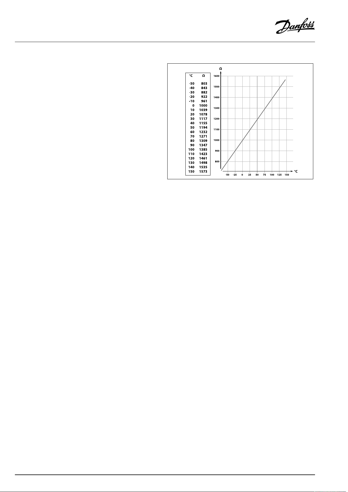
Pt1000temperaturesensor(IEC751B,1000Ω/0°C)
Relationshipbetweentemperatureandohmicvalue:
16|©Danfoss|2021.03
AQ005186455839en-010401
Page 17
OperatingGuideECLComfort310,applicationA367
2.5Electricalconnections
2.5.1Electricalconnections230Va.c.
Warning
ElectricconductorsonPCB(PrintedCircuitBoard)forsupplyvoltage,
relaycontactsandtriacoutputsdonothavemutualsafetydistanceof
minimum6mm.Theoutputsarenotallowedtobeusedasgalvanic
separated(voltfree)outputs.
Ifagalvanicseparatedoutputisneeded,anauxiliaryrelayis
recommended.
24Voltcontrolledunits,forexampleactuators,aretobecontrolledby
meansofECLComfort310,24Voltversion.
SafetyNote
Necessaryassembly,start-up,andmaintenanceworkmustbe
performedbyqualifiedandauthorizedpersonnelonly.
Locallegislationsmustberespected.Thiscomprisesalsocablesize
andisolation(reinforcedtype).
AfusefortheECLComfortinstallationismax.10Atypically.
TheambienttemperaturerangefortheECLComfortinoperationis
0-55°C.Exceedingthistemperaturerangecanresultinmalfunctions.
Installationmustbeavoidedifthereisariskforcondensation(dew).
AQ005186455839en-010401
©Danfoss|2021.03|17
Page 18
OperatingGuideECLComfort310,applicationA367
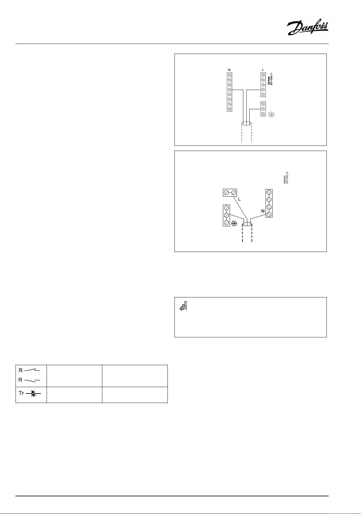
Thecommongroundterminalisusedforconnectionofrelevant
components(pumps,motorizedcontrolvalves).
ECL210/310
ECL296
SeealsotheInstallationGuide(deliveredwiththeapplicationkey)
forapplicationspecificconnections.
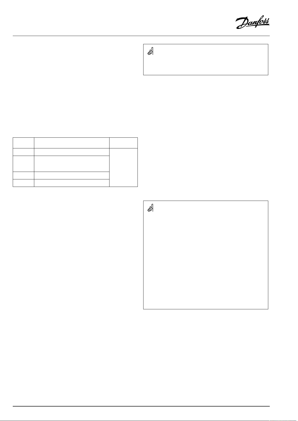
Maximumloadratings:
Relayterminals
4(2)A/230Va.c.
(4Aforohmicload,2Afor
inductiveload)
Triac(=electronic
0,2A/230Va.c.
relay)terminals
Wirecrosssection:0.5-1.5mm²
Incorrectconnectioncandamagetheelectronicoutputs.
Max.2x1.5mm²wirescanbeinsertedintoeachscrewterminal.
18|©Danfoss|2021.03
AQ005186455839en-010401
Page 19
OperatingGuideECLComfort310,applicationA367
2.5.2Electricalconnections24Va.c.
SeealsotheInstallationGuide(deliveredwiththeapplicationkey)
forapplicationspecificconnections.
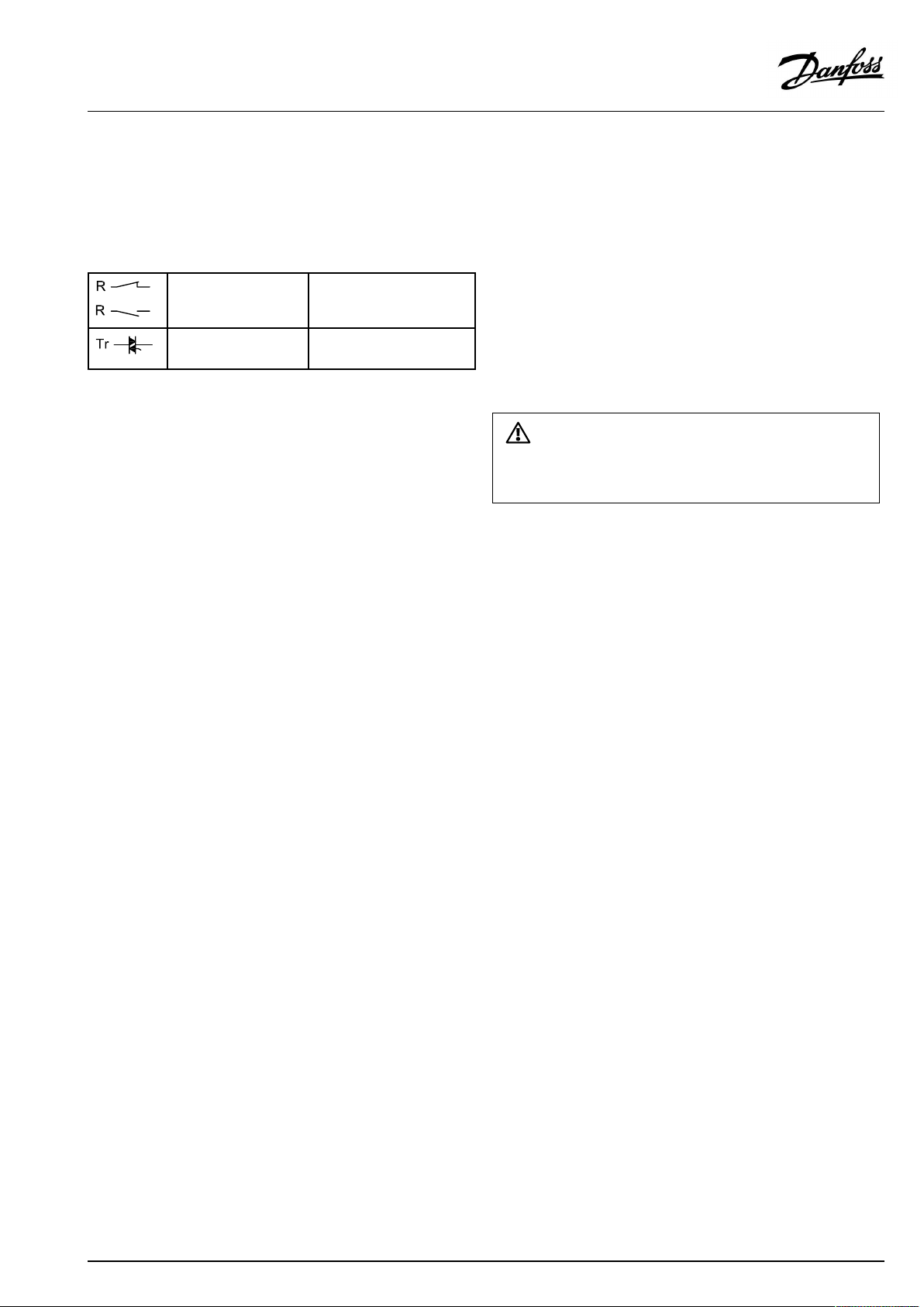
Maximumloadratings:
Relayterminals
Triac(=electronic
relay)terminals
4(2)A/24Va.c.
(4Aforohmicload,2Afor
inductiveload)
1A/24Va.c.
Donotconnect230Va.c.poweredcomponentstoa24Va.c.power
suppliedcontrollerdirectly.Useauxilliaryrelays(K)toseparate230
Va.c.from24Va.c.
AQ005186455839en-010401
©Danfoss|2021.03|19
Page 20
OperatingGuideECLComfort310,applicationA367
2.5.3Electricalconnections,safetythermostats,ingeneral
SeealsotheInstallationGuide(deliveredwiththeapplicationkey)
forapplicationspecificconnections.
WhenSTisactivatedbyahightemperature,thesafetycircuitinthe
motorizedcontrolvalveclosesthevalveimmediately.
WhenST1isactivatedbyahightemperature(theTRtemperature),the
motorizedcontrolvalveisclosedgradually.Atahighertemperature
(theSTtemperature),thesafetycircuitinthemotorizedcontrolvalve
closesthevalveimmediately.
20|©Danfoss|2021.03
AQ005186455839en-010401
Page 21
OperatingGuideECLComfort310,applicationA367
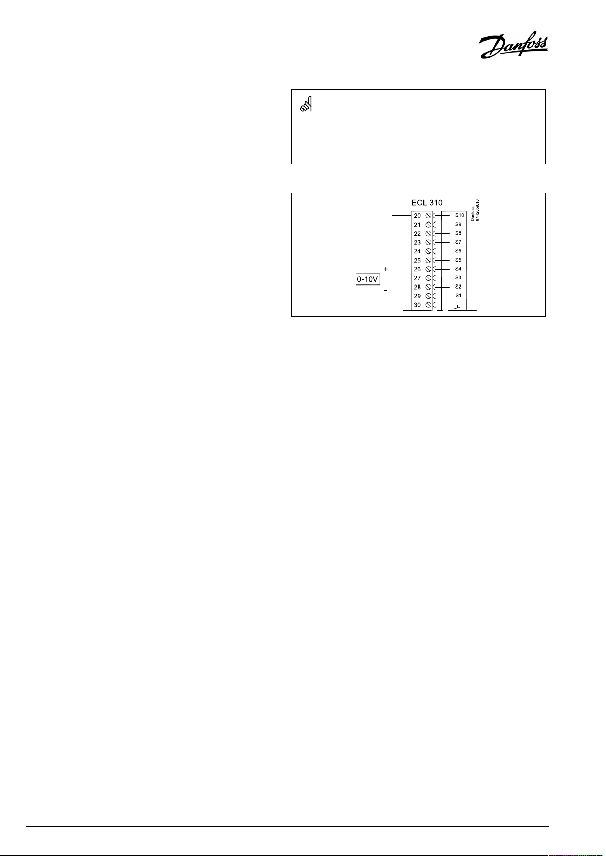
2.5.4Electricalconnections,Pt1000temperaturesensorsandsignals
SeetheInstallationGuide(deliveredwiththeapplicationkey)for
sensorandinputconnections.
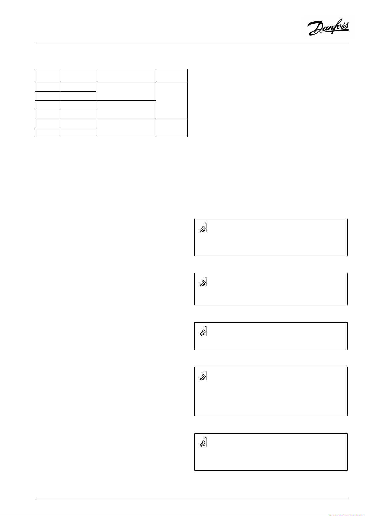
A367:
Sensor
S1
S2Returntemperaturesensor,
S3
S4
S5Returntemperaturesensor,
S6
S7Roomtemperature
S8
S10
Description
Outdoortemperature
sensor*
heatingcircuit2
Flowtemperaturesensor,
heatingcircuit1**
Flowtemperaturesensor,
heatingcircuit2**
heatingcircuit1
DHWtanktemperature
sensor,upper***
sensor****:
A367.1:heatingcircuit1
A367.2:heatingcircuit1/
heatingcircuit2
DHWtanktemperature
sensor,lower
Roomtemperature
sensor****:
A367.1heatingcircuit2only
DHWchargingtemperature
sensor:
A367.2DHWcircuitonly
Voltagesignal(0-10V)for
externalcontrolofdesired
flowtemperature,heating
circuit1
Type
(recomm.)
ESMT
ESM-11/ESMB/
ESMC/ESMU
ESM-11/ESMB/
ESMC/ESMU
ESM-11/ESMB/
ESMC/ESMU
ESM-11/ESMB/
ESMC/ESMU
ESMB/
ESMU
ESM-10
ESMB/
ESMU
ESM-10 S9
ESM-11/ESMB/
ESMC/ESMU
*
Iftheoutdoortemperaturesensorisnotconnectedorthe
cableisshort-circuited,thecontrollerassumesthatthe
outdoortemperatureis0(zero)°C.Theoutdoortemperature
sensoriscommonforbothheatingcircuits.
**
Theflowtemperaturesensormustalwaysbeconnected
inordertohavethedesiredfunctionality.Ifthesensoris
notconnectedorthecableisshort-circuited,themotorized
controlvalvecloses(safetyfunction).
***
Thissensorisusedifonlyonetanktemperaturesensoris
required.
****
Onlyforroomtemperaturesensorconnection.Theroom
temperaturesignalcanalternativelybeavailablefroma
RemoteControlUnit(ECA30/31).See'Electricalconnections,
ECA30/31'.
AQ005186455839en-010401
©Danfoss|2021.03|21
Page 22
OperatingGuideECLComfort310,applicationA367
Connectionofvoltagesignal(0–10V)forexternalcontrolof
desiredflowtemperature
Wirecrosssectionforsensorconnections:Min.0.4mm².
Totalcablelength:Max.200m(allsensorsincl.internalECL485
communicationbus)
Cablelengthsofmorethan200mmaycausenoisesensibility(EMC).
22|©Danfoss|2021.03
AQ005186455839en-010401
Page 23
OperatingGuideECLComfort310,applicationA367
2.5.5Electricalconnections,ECA30/31
Terminal
ECL
Terminal
ECA30/31
30
31
4
1
322
333
4
5
*
Afteranexternalroomtemperaturesensorhasbeenconnected,
Description
Twistedpair
Twistedpair
Ext.roomtemperature
sensor*
Type
(recomm.)
Cable2x
twistedpair
ESM-10
ECA30/31mustberepowered.
ThecommunicationtotheECA30/31mustbesetupintheECL
Comfortcontrollerin'ECAaddr.'
TheECA30/31mustbesetupaccordingly.
AfterapplicationsetuptheECA30/31isreadyafter2–5min.A
progressbarintheECA30/31isdisplayed.
Iftheactualapplicationcontainstwoheatingcircuits,itispossible
toconnectanECA30/31toeachcircuit.Theelectricalconnections
aredoneinparallel.
Max.2ECA30/31canbeconnectedtoanECLComfort310controller
ortoECLComfort210/296/310controllersinamaster-slavesystem.
SetupproceduresforECA30/31:Seesection‘Miscellaneous’ .
ECAinformationmessage:
‘Applicationreq.newerECA’:
Thesoftware(firmware)ofyourECAdoesnotcomplywiththe
software(firmware)ofyourECLComfortcontroller.Pleasecontact
yourDanfosssalesoffice.
Someapplicationsdonotcontainfunctionsrelatedtoactualroom
temperature.TheconnectedECA30/31willonlyfunctionasremote
control.
AQ005186455839en-010401
©Danfoss|2021.03|23
Page 24
OperatingGuideECLComfort310,applicationA367
2.5.6Electricalconnections,master/slavesystems
Thecontrollercanbeusedasmasterorslaveinmaster/slave
systemsviatheinternalECL485communicationbus(2xtwisted
paircable).
TheECL485communicationbusisnotcompatiblewiththeECL
businECLComfort110,200,300and301!
Totalcablelength:Max.200m(allsensorsincl.internalECL485
communicationbus).
Cablelengthsofmorethan200mmaycausenoisesensibility(EMC).
Terminal
Description
Type
(recomm.)
30
Commonterminal
+12V*,ECL485communicationbus
31
*OnlyforECA30/31andmaster/
slavecommunication
32
B,ECL485communicationbus
33
A,ECL485communicationbus
Cable2x
twistedpair
ECL485buscable
MaximumrecommendedlengthoftheECL485busiscalculatedlike
this:
Subtract"TotallengthofallinputcablesofallECLcontrollersinthe
master-slavesystem"from200m.
Simpleexamplefortotallengthofallinputcables,3xECL:
1xECL
3xECL
3xECLReturntemp.sensor:
3xECLRoomtemp.sensor:
Total:
Outdoortemp.sensor:
Flowtemp.sensor:
15m
18m
18m
30m
81m
2.5.7Electricalconnections,communication
Electricalconnections,Modbus
ECLComfort210:Non-galvanicisolatedModbusconnections
ECLComfort296:GalvanicisolatedModbusconnections
ECLComfort310:GalvanicisolatedModbusconnections
24|©Danfoss|2021.03
MaximumrecommendedlengthoftheECL485bus:
200-81m=119m
AQ005186455839en-010401
Page 25

OperatingGuideECLComfort310,applicationA367
2.5.8Electricalconnections,communication
Electricalconnections,M-bus
ECLComfort210:Notimplemented
ECLComfort296:Onboard,non-galvanicisolated.Max.cable
length50m.
ECLComfort310:Onboard,non-galvanicisolated.Max.cable
length50m.
AQ005186455839en-010401
©Danfoss|2021.03|25
Page 26
OperatingGuideECLComfort310,applicationA367
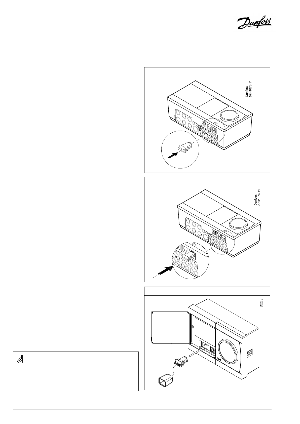
2.6InsertingtheECLApplicationKey
2.6.1InsertingtheECLApplicationKey
TheECLApplicationKeycontains
•theapplicationanditssubtypes,
•currentlyavailablelanguages,
•factorysettings:e.g.schedules,desiredtemperatures,
limitationvaluesetc.Itisalwayspossibletorecoverthefactory
settings,
•memoryforusersettings:specialuser/systemsettings.
Afterhavingpowered-upthecontroller,differentsituationsmight
beexisting:
1.Thecontrollerisnewfromthefactory,theECLApplicationKey
isnotinserted.
2.Thecontrolleralreadyrunsanapplication.TheECLApplication
Keyisinserted,buttheapplicationneedstobechanged.
3.Acopyofthecontrollerssettingsisneededforconfiguring
anothercontroller.
ECLComfort210/310
ECLComfort210/310
Usersettingsare,amongothers,desiredroomtemperature,desired
DHWtemperature,schedules,heatcurve,limitationvaluesetc.
Systemsettingsare,amongothers,communicationset-up,display
brightnessetc.
26|©Danfoss|2021.03
ECLComfort296
AQ005186455839en-010401
Page 27
OperatingGuideECLComfort310,applicationA367
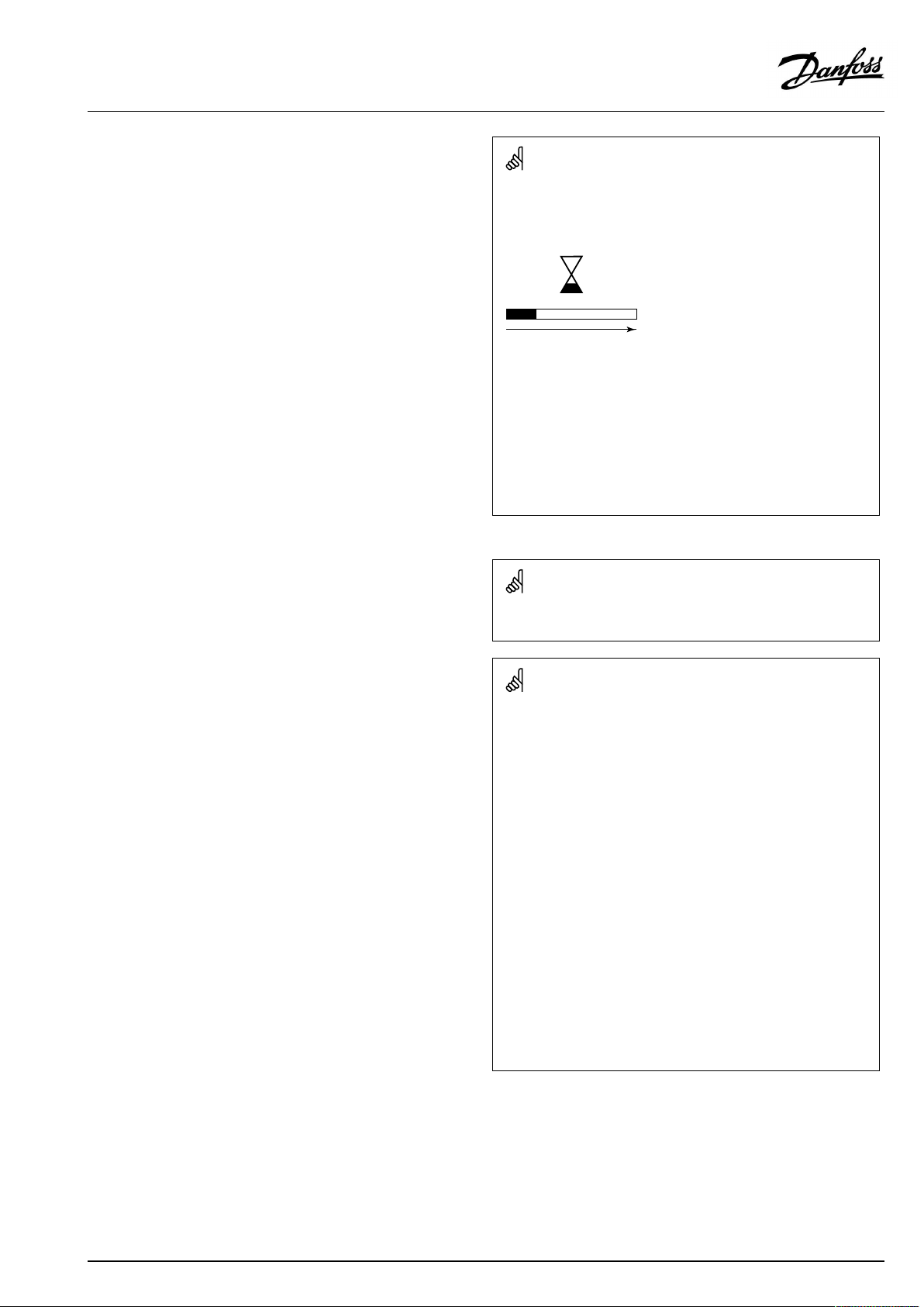
Automaticupdateofcontrollersoftware(firmware):
Thesoftwareofthecontrollerisupdatedautomaticallywhenthekey
isinserted(asofcontrollerversion1.11(ECL210/310)andversion
1.58(ECL296)).Thefollowinganimationwillbeshownwhenthe
softwareisbeingupdated:
Progressbar
Duringupdate:
•DonotremovetheKEY
Ifthekeyisremovedbeforethehour-glassisshown,youhave
tostartafresh.
•Donotdisconnectthepower
Ifthepowerisinterruptedwhenthehour-glassisshown,the
controllerwillnotwork.
•Manualupdateofcontrollersoftware(firmware):
Seethesection"Automatic/manualupdateoffirmware"
The“Keyoverview”doesnotinform—throughECA30/31—about
thesubtypesoftheapplicationkey.
Keyinserted/notinserted,description:
ECLComfort210/310,controllerversionslowerthan1.36:
-
Takeouttheapplicationkey;for20minutes
settingscanbechanged.
-
Powerupthecontrollerwithoutthe
applicationkeyinserted;for20minutes
settingscanbechanged.
ECLComfort210/310,controllerversions1.36andup:
-
Takeouttheapplicationkey;for20minutes
settingscanbechanged.
-
Powerupthecontrollerwithoutthe
applicationkeyinserted;settingscannotbe
changed.
ECLComfort296,controllerversions1.58andup:
-
Takeouttheapplicationkey;for20minutes
settingscanbechanged.
-
Powerupthecontrollerwithoutthe
applicationkeyinserted;settingscannotbe
changed.
AQ005186455839en-010401
©Danfoss|2021.03|27
Page 28
OperatingGuideECLComfort310,applicationA367
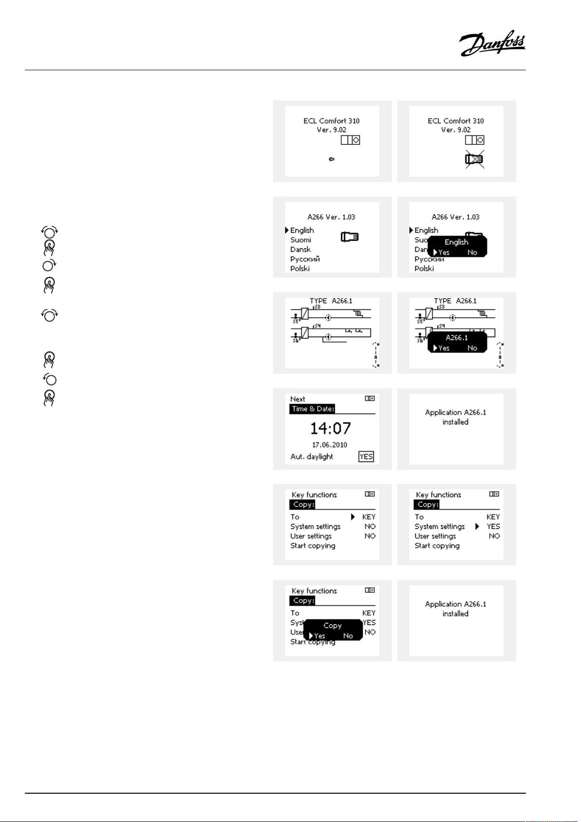
ApplicationKey:Situation1
Thecontrollerisnewfromthefactory,theECLApplicationKey
isnotinserted.
AnanimationfortheECLApplicationKeyinsertionisdisplayed.
InserttheApplicationKey.
ApplicationKeynameandVersionisindicated(example:A266
Ver.1.03).
IftheECLApplicationKeyisnotsuitableforthecontroller,a"cross"
isdisplayedovertheECLApplicationKey-symbol.
Action:Purpose:
Selectlanguage
Confirm
Selectapplication(subtype)
Somekeyshaveonlyoneapplication.
Confirmwith‘Yes’
Set'Time&Date'
Turnandpushthedialtoselectand
change'Hours' ,'Minutes','Date',
'Month'and'Year' .
Choose''Next'
Confirmwith‘Yes’
Goto‘Aut.daylight’
Choosewhether‘ Aut.daylight´*
shouldbeactiveornot
*‘Aut.daylight’istheautomaticchangeoverbetweensummer
andwintertime.
DependingonthecontentsoftheECLApplicationKey,procedure
AorBistakingplace:
A
TheECLApplicationkeycontainsfactorysettings:
Thecontrollerreads/transfersdatafromtheECLApplicationKey
toECLcontroller.
Examples:
YESorNO
Theapplicationisinstalled,andthecontrollerresetsandstartsup.
B
TheECLApplicationkeycontainschangedsystemsettings:
Pushthedialrepeatedly.
’NO’:
’YES*:
Ifthekeycontainsusersettings:
Pushthedialrepeatedly.
‘NO:
‘YES*:
*If‘YES’cannotbechosen,theECLApplicationKeydoesnot
containanyspecialsettings.
Choose‘Startcopying’andconfirmwith'Yes'.
28|©Danfoss|2021.03
OnlyfactorysettingsfromtheECLApplicationKeywill
becopiedtothecontroller.
Specialsystemsettings(differingfromthefactory
settings)willbecopiedtothecontroller.
OnlyfactorysettingsfromtheECLApplicationKeywill
becopiedtothecontroller.
Specialusersettings(differingfromthefactorysettings)
willbecopiedtothecontroller.
AQ005186455839en-010401
Page 29
OperatingGuideECLComfort310,applicationA367
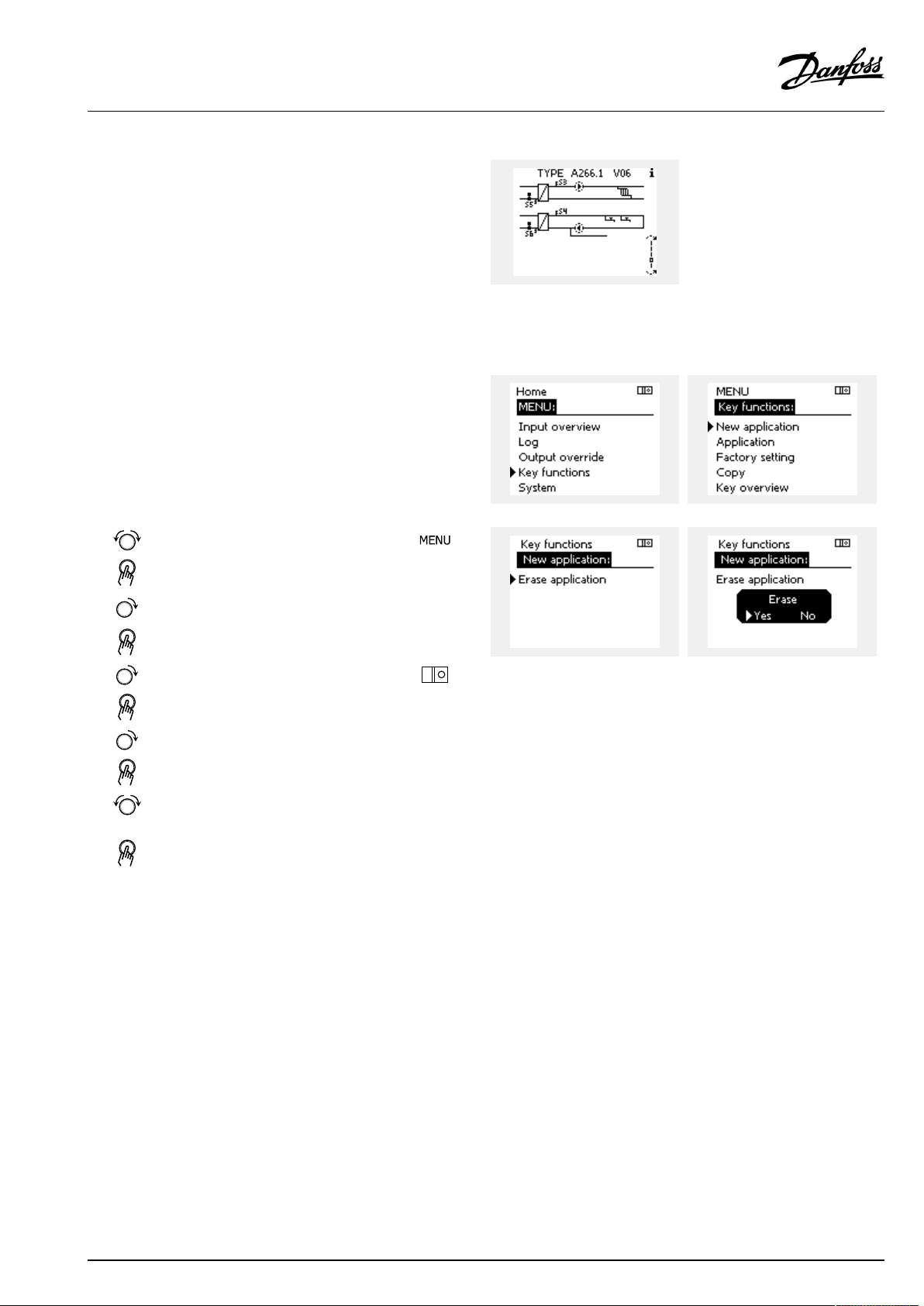
(Example):
The"i"intheupperrightcornerindicatesthat-besidesthefactory
settings-thesubtypealsocontainsspecialuser/systemssettings.
ApplicationKey:Situation2
Thecontrolleralreadyrunsanapplication.TheECLApplication
Keyisinserted,buttheapplicationneedstobechanged.
TochangetoanotherapplicationontheECLApplicationKey,the
currentapplicationinthecontrollermustbeerased(deleted).
BeawarethattheApplicationKeymustbeinserted.
Action:Purpose:
Choose‘MENU’inanycircuit
Confirm
Choosethecircuitselectoratthetop
rightcornerinthedisplay
Confirm
Choose‘Commoncontrollersettings’
Confirm
Choose‘Keyfunctions’
Confirm
Choose‘Eraseapplication’
Confirmwith‘Yes’
Thecontrollerresetsandisreadytobeconfigured.
Followtheproceduredescribedinsituation1.
Examples:
AQ005186455839en-010401
©Danfoss|2021.03|29
Page 30
OperatingGuideECLComfort310,applicationA367
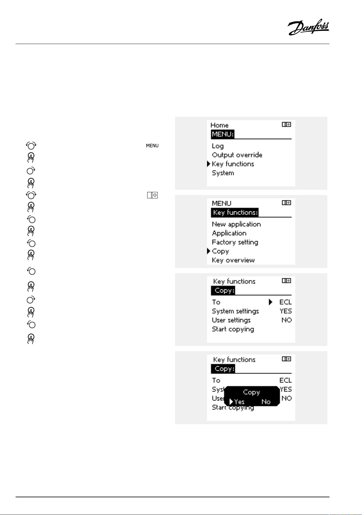
ApplicationKey:Situation3
Acopyofthecontrollerssettingsisneededforconfiguring
anothercontroller.
Thisfunctionisused
•forsaving(backup)ofspecialuserandsystemsettings
•whenanotherECLComfortcontrollerofthesametype(210,
296or310)mustbeconfiguredwiththesameapplicationbut
user/systemsettingsdifferfromthefactorysettings.
HowtocopytoanotherECLComfortcontroller:
Action:Purpose:
Choose‘MENU’
Confirm
Choosethecircuitselectoratthetop
rightcornerinthedisplay
Confirm
Choose'Commoncontrollersettings'
Confirm
Goto‘Keyfunctions’
Confirm
Choose‘Copy’
Confirm
Choose‘To’ .
‘ECL’or‘KEY’willbeindicated.Choose
’ECL’orKEY’
Pushthedialrepeatedlytochoose
copydirection
Choose‘Systemsettings’or‘User
settings’
Pushthedialrepeatedlytochoose
‘Yes’or‘No’in‘Copy’ .Pushtoconfirm.
Choose‘Startcopying’
TheApplicationKeyorthecontroller
isupdatedwithspecialsystemoruser
settings.
Examples:
*
’ECL’or‘KEY’ .
**
‘NO’or‘YES’
*
‘ECL’:
‘KEY’:
**
‘NO’:
‘YES’:
30|©Danfoss|2021.03
DatawillbecopiedfromtheApplicationKeytothe
ECLController.
DatawillbecopiedfromtheECLControllertothe
ApplicationKey.
ThesettingsfromtheECLcontrollerwillnotbecopied
totheApplicationKeyortotheECLComfortcontroller.
Specialsettings(differingfromthefactorysettings)will
becopiedtotheApplicationKeyortotheECLComfort
controller.IfYEScannotbechosen,therearenospecial
settingstobecopied.
AQ005186455839en-010401
Page 31
OperatingGuideECLComfort310,applicationA367
Language
Atapplicationupload,alanguagemustbeselected.*
IfanotherlanguagethanEnglishisselected,theselectedlanguage
ANDEnglishwillbeuploadedintotheECLcontroller.
ThismakesserviceeasyforEnglishspeakingservicepeople,just
becausetheEnglishlanguagemenuscanbevisiblebychanging
theactualsetlanguageintoEnglish.
(Navigation:MENU>Commoncontroller>System>Language)
Iftheuploadedlanguageisnotsuitable,theapplicationmustbe
erased.UserandSystemsettingscanbesavedontheapplication
keybeforeerasing.
Afternewuploadwithpreferredlanguage,theexistingUserand
Systemsettingscanbeuploaded.
*)
(ECLComfort310,24Volt)Iflanguagecannotbeselected,the
powersupplyisnota.c.(alternatingcurrent).
2.6.2ECLApplicationKey,copyingdata
Generalprinciples
Whenthecontrollerisconnectedandoperating,youcancheck
andadjustallorsomeofthebasicsettings.Thenewsettingscan
bestoredontheKey.
Factorysettingscanalwaysberestored.
HowtoupdatetheECLApplicationKeyaftersettingshave
beenchanged?
AllnewsettingscanbestoredontheECLApplicationKey.
Howtostorefactorysettinginthecontrollerfromthe
ApplicationKey?
PleasereadtheparagraphconcerningApplicationKey,Situation
1:Thecontrollerisnewfromthefactory,theECLApplicationKey
isnotinserted.
HowtostorepersonalsettingsfromthecontrollertotheKey?
PleasereadtheparagraphconcerningApplicationKey,Situation3:
Acopyofthecontrollerssettingsisneededforconfiguringanother
controller
Asamainrule,theECLApplicationKeyshouldalwaysremainin
thecontroller.IftheKeyisremoved,itisnotpossibletochange
settings.
Makeanoteofnewsettingsinthe'Settingsoverview'table.
DonotremovetheECLApplicationKeywhilecopying.Thedataon
theECLApplicationKeycanbedamaged!
ItispossibletocopysettingsfromoneECLComfortcontrollerto
anothercontrollerprovidedthatthetwocontrollersarefromthesame
series(210or310).
Furthermore,whentheECLComfortcontrollerhasbeenuploaded
withanapplicationkey,minimumversion2.44,itispossibletoupload
personalsettingsfromapplicationkeys,minimumversion2.14.
AQ005186455839en-010401
©Danfoss|2021.03|31
Page 32

OperatingGuideECLComfort310,applicationA367
The“Keyoverview”doesnotinform—throughECA30/31—about
thesubtypesoftheapplicationkey.
Keyinserted/notinserted,description:
ECLComfort210/310,controllerversionslowerthan1.36:
-
Takeouttheapplicationkey;for20minutes
settingscanbechanged.
-
Powerupthecontrollerwithoutthe
applicationkeyinserted;for20minutes
settingscanbechanged.
ECLComfort210/310,controllerversions1.36andup:
-
Takeouttheapplicationkey;for20minutes
settingscanbechanged.
-
Powerupthecontrollerwithoutthe
applicationkeyinserted;settingscannotbe
changed.
ECLComfort296,controllerversions1.58andup:
-
Takeouttheapplicationkey;for20minutes
settingscanbechanged.
-
Powerupthecontrollerwithoutthe
applicationkeyinserted;settingscannotbe
changed.
32|©Danfoss|2021.03
AQ005186455839en-010401
Page 33

OperatingGuideECLComfort310,applicationA367
2.7Checklist
IstheECLComfortcontrollerreadyforuse?
Makesurethatthecorrectpowersupplyisconnectedtoterminals9and10(230Vor24V).
Makesurethecorrectphaseconditionsareconnected:
230V:Live=terminal9andNeutral=terminal10
24V:SP=terminal9andSN=terminal10
Checkthattherequiredcontrolledcomponents(actuator,pumpetc.)areconnectedtothecorrectterminals.
Checkthatallsensors/signalsareconnectedtothecorrectterminals(see'Electricalconnections').
Mountthecontrollerandswitchonthepower.
IstheECLApplicationKeyinserted(see'InsertingtheApplicationKey').
DoestheECLComfortcontrollercontainanexistingapplication(see'InsertingtheApplicationKey').
Isthecorrectlanguagechosen(see'Language'in'Commoncontrollersettings').
Isthetime&datesetcorrectly(see'Time&Date'in'Commoncontrollersettings').
Istherightapplicationchosen(see'Identifyingthesystemtype').
Checkthatallsettingsinthecontroller(see'Settingsoverview')aresetorthatthefactorysettingscomplywithyour
requirements.
Choosemanualoperation(see'Manualcontrol').Checkthatvalvesopenandclose,andthatrequiredcontrolled
components(pumpetc.)startandstopwhenoperatedmanually.
Checkthatthetemperatures/signalsshowninthedisplaymatchtheactualconnectedcomponents.
Havingcompletedthemanualoperationcheck,choosecontrollermode(scheduled,comfort,savingorfrostprotection).
AQ005186455839en-010401
©Danfoss|2021.03|33
Page 34

OperatingGuideECLComfort310,applicationA367
2.8Navigation,ECLApplicationKeyA367
Navigation,applicationA367.1andA367.2(*A367.2only)
Home
MENU
ScheduleSelectableSelectableSelectable
Schedulecirc.PSelectable
Settings
Flowtemperature
(circuit1)
Tanktemperature
(circuit3)
Roomlimit
Returnlimit
Flow/powerlimitActualActualActual
Optimization
Controlpar.
Heating,circuit1Heating,circuit2DHW,circuit3
IDno.
11178
11177
11182
11183
11015
11031
11032
11033
11034
11035
11036
11037
11085
11119
11117
11118
11116
11112
11113
11109
11115
11011
11012
11013
11014
11026
11020
11021
11179
11043
11174
11184
11185
11186
11187
11189
Function
HeatcurveHeatcurve13193Chargedifference
Temp.max.
Temp.min.
Ext.desiredT
Infl.—max.
Infl.—min.
Adapt.time
HighToutX1
LowlimitY1
LowToutX2
HighlimitY2
Infl.-max.
Infl.-min.
Adapt.time
Priority
ActuallimitActuallimit
HighToutX1
LowlimitY1
LowToutX2
HighlimitY2
Adapt.time
Filterconstant
Inputtype
Units
Autosaving
Boost
Ramp
Optimizer
Prestop
Basedon
Totalstop
Cut-out
Paralleloperation
Motorpr.
Xp
Tn
Mrun
Nz
Min.act.time
IDno.
12178
12177
12182
12183
12015
11031
12032
12033
12034
12035
12036
12037
12085
12119
12117
12118
12116
12112
12113
12109
12115
12011
12012
12013
12014
12026
12020
12021
12179
12174
12184
12185
12186
12187
12189
Function
Temp.max.
Temp.min.
Infl.—max.
Infl.—min.
Adapt.time
HighToutX1
LowlimitY1
LowToutX2
HighlimitY2
Infl.-max.
Infl.-min.
Adapt.time
Priority
HighToutX1
LowlimitY1
LowToutX2
HighlimitY2
Adapt.time
Filterconstant
Inputtype
Units
Autosaving
Boost
Ramp
Optimizer
Prestop
Basedon
Totalstop
Cut-out
Motorpr.
Xp
Tn
Mrun
Nz
Min.act.time
IDno.
13195
13194
13152
13068
13030
13111
Function
Startdifference
Stopdifference
Max.chargeT
FlowTadapttime*
Limit
Limit
34|©Danfoss|2021.03
AQ005186455839en-010401
Page 35

OperatingGuideECLComfort310,applicationA367
Navigation,applicationA367.1and367.2continued(*A367.1only,**A367.2only)
Home
MENU
Settings
HolidaySelectableSelectableSelectable
Alarm
Influence
overview
Application
Anti-bacteriaSelectable
Temp.monitor.
AlarmoverviewSelectableSelectable
Des.flowT
(circuits1&2)
Des.DHWT
(circuit3)
Heating,circuit1Heating,circuit2DHW,circuit3
IDno.
11010
11017
11050
11500
11022
11023
11052
11077
11078
11040
11093
11141
11142
11147
11148
11149
11150
Function
ECAaddr.
Demandoffset
Pdemand
SenddesiredT
Pexercise
Mexercise
DHWpriority
PfrostT
PheatT
Ppost-run
Frostpr.T
Ext.input
Ext.mode
Upperdifference
Lowerdifference
Delay
Lowesttemp.
Returnlim.Returnlim.Holiday
Roomlim.Roomlim.Ext.override
Flow/powerlim.Flow/powerlim.Anti-bacteria
HolidayHolidaySCADAoverride
Ext.overrideExt.override
ECAoverrideECAoverride
BoostBoost
RampRamp
Slave,demand
Heatingcut-outHeatingcut-out
DHWpriorityDHWpriority
DHWinfluence
SCADAoffsetSCADAoffset
Ext.desiredT
IDno.
12010
12500
12022
12023
12052
12077
12078
12040
12093
12141
12142
12147
12148
12149
12150
Function
ECAaddr.
SenddesiredT
Pexercise
Mexercise
DHWpriority
PfrostT
PheatT
Ppost-run
Frostpr.T
Ext.input
Ext.mode
Upperdifference
Lowerdifference
Delay
Lowesttemp.
IDno.
13051
13053
13055
13044
13045
13041
13042
13500
13076
13093
13141
13142
Function
Ch.-o.valve/P
Tank,sec./prim.*
Circ.Ppriority
Max.DHWtime
DHWdeact.time
DHWPpost-run
Char.Ppost-run**
SenddesiredT
Circ.PfrostT
Frostpr.T
Ext.input
Ext.mode
AQ005186455839en-010401
©Danfoss|2021.03|35
Page 36

OperatingGuideECLComfort310,applicationA367
Navigation,applicationA367.1andA367.2(*A367.2only),Commoncontrollersettings
Home
MENU
Time&Date
HolidaySelectable
InputoverviewsCircuit1Circuit2Circuit3
Log1,2&3(sensors)
Outputoverride
Keyfunctions
SystemECLversion
LogtodayOutdoorTOutdoorTTankTup.&des.
Logyesterday
Log2daysFlowT&desiredFlowT&desired
Log4daysReturnT&limitReturnT&limit
NewapplicationEraseapplication
Application
FactorysettingSystemsettings
Copy
Keyoverview
Extension
Ethernet
M-busconfig
EnergyMeters
Display
Communication
Language
IDno.
60058
60059
2048
2150
2151
2050
Function
Selectable
OutdoorTOutdoorTTankupperT
Outdooracc.TOutdooracc.TTanklowerT
RoomTRoomT
FlowTFlowT
ReturnTReturnT
Ext.desiredT
RoomTRoomT
M1,P1,M2,P5,P2,P3,P4*,A1
Usersettings
Gotofactory
To
Systemsettings
Usersettings
Startcopying
Codeno.
Hardware
Software
Buildno.
Serialno.
MAC
Productionweek
Selectable
Selectable
Backlight
Contrast
38
Modbusaddr.
ECL485addr.
Servicepin
Ext.reset
Language
Commoncontrollersettings
ChargeT*
TankTup.&low.
36|©Danfoss|2021.03
AQ005186455839en-010401
Page 37

OperatingGuideECLComfort310,applicationA367
3.0Dailyuse
3.1Howtonavigate
Younavigateinthecontrollerbyturningthedialleftorrightto
thedesiredposition().
Thedialhasabuilt-inaccellerator.Thefasteryouturnthedial,the
fasteritreachesthelimitsofanywidesettingrange.
Thepositionindicatorinthedisplay(
youare.
Pushthedialtoconfirmyourchoices().
Thedisplayexamplesarefromatwo-circuitapplication:One
heatingcircuit()andonedomestichot-water(DHW)circuit().
Theexamplesmightdifferfromyourapplication.
)willalwaysshowyouwhere
ExampleshowsECL210/310
Heatingcircuit():DHWcircuit();
Somegeneralsettingswhichapplytotheentirecontrollerare
locatedinaspecificpartofthecontroller.
Toenter‘Commoncontrollersettings’:
Action:Purpose:
Choose‘MENU’inanycircuit
Confirm
Choosethecircuitselectoratthetop
rightcornerinthedisplay
Confirm
Choose‘Commoncontrollersettings’
Confirm
Examples:
Circuitselector
AQ005186455839en-010401
©Danfoss|2021.03|37
Page 38

OperatingGuideECLComfort310,applicationA367
3.2Understandingthecontrollerdisplay
ThissectiondescribesthefunctioningeneralfortheECLComfort
210/296/310series.Theshowndisplaysaretypicalandnot
applicationrelated.Theymightdifferfromthedisplaysinyour
application.
Choosingafavoritedisplay
Yourfavoritedisplayisthedisplayyouhavechosenasthedefault
display.Thefavoritedisplaywillgiveyouaquickoverviewofthe
temperaturesorunitsthatyouwanttomonitoringeneral.
Ifthedialhasnotbeenactivatedfor20min.,thecontrollerwill
reverttotheoverviewdisplayyouhavechosenasfavorite.
Toshiftbetweendisplays:Turnthedialuntilyoureachthedisplay
selector(
turntochooseyourfavoriteoverviewdisplay.Pushthedialagain.
)atthebottomrightsideofthedisplay.Pushthedialand
Heatingcircuit
Overviewdisplay1informsabout:
actualoutdoortemperature,controllermode,
actualroomtemperature,desiredroomtemperature.
Overviewdisplay2informsabout:
actualoutdoortemperature,trendinoutdoortemperature,
controllermode,max.andmin.outdoortemperaturessince
midnightaswellasdesiredroomtemperature.
Overviewdisplay3informsabout:
date,actualoutdoortemperature,controllermode,time,desired
roomtemperatureaswellasshowsthecomfortscheduleofthe
currentday.
Overviewdisplay4informsabout:
stateofthecontrolledcomponents,actualflowtemperature,
(desiredflowtemperature),controllermode,returntemperature
(limitationvalue),influenceondesiredflowtemperature.
ThevalueabovetheV2symbolindicates0–100%oftheanalogue
signal(0–10V).
Note:
Anactualflowtemperaturevaluemustbepresent,otherwisethe
circuit'scontrolvalvewillclose.
Overviewdisplay1:Overviewdisplay2:
Overviewdisplay3:Overviewdisplay4:
Exampleofoverviewdisplaywith
Influenceindication:
Example,favoritedisplay1in
A230.3,wheremin.desiredroom
temperatureisindicated(22.7):
Dependentonthechosendisplay,theoverviewdisplaysforthe
heatingcircuitinformyouabout:
•actualoutdoortemperature(-0.5)
•controllermode()
•actualroomtemperature(24.5)
•desiredroomtemperature(20.7°C)
•trendinoutdoortemperature(
)
•min.andmax.outdoortemperaturessincemidnight(
•date(23.02.2010)
•time(7:43)
•comfortscheduleofthecurrentday(0-12-24)
•stateofthecontrolledcomponents(M2,P2)
•actualflowtemperature(49°C),(desiredflowtemperature(31))
•returntemperature(24°C)(limitationtemperature(50))
38|©Danfoss|2021.03
)
AQ005186455839en-010401
Page 39

OperatingGuideECLComfort310,applicationA367
Thesettingofthedesiredroomtemperatureisimportantevenifa
roomtemperaturesensor/RemoteControlUnitisnotconnected.
Ifthetemperaturevalueisdisplayedas
"--"
thesensorinquestionisnotconnected.
"---"
thesensorconnectionisshort-circuited.
DHWcircuit
Overviewdisplay1informsabout:
actualDHWtemperature,controllermode,desiredDHW
temperatureaswellasthecomfortscheduleofthecurrentday.
Overviewdisplay2informsabout:
stateofthecontrolledcomponents,actualDHWtemperature,
(desiredDHWtemperature),controllermode,returntemperature
(limitationvalue),influenceondesiredDHWtemperature.
Dependentonchosendisplay,theoverviewdisplaysfortheDHW
circuitinformyouabout:
•actualDHWtemperature(50.3)
•controllermode(
)
•desiredDHWtemperature(50°C)
•comfortscheduleofthecurrentday(0-12-24)
•stateofthecontrolledcomponents(M1,P1)
•actualDHWtemperature(50°C),(desiredDHWtemperature(50))
•returntemperature(--°C)(limitationtemperature(30))
Settingthedesiredtemperature
Dependingonthechosencircuitandmode,itispossibletoenter
alldailysettingsdirectlyfromtheoverviewdisplays(seealsothe
nextpageconcerningsymbols).
Overviewdisplay1:Overviewdisplay2:
Exampleofoverviewdisplaywith
Influenceindication:
AQ005186455839en-010401
©Danfoss|2021.03|39
Page 40

OperatingGuideECLComfort310,applicationA367
Settingthedesiredroomtemperature
Thedesiredroomtemperaturecaneasilybeadjustedinthe
overviewdisplaysfortheheatingcircuit.
Action:Purpose:
Examples:
Desiredroomtemperature
Confirm
Adjustthedesiredroomtemperature
Confirm
Thisoverviewdisplayinformsaboutoutdoortemperature,actual
roomtemperatureaswellasdesiredroomtemperature.
Thedisplayexampleisforcomfortmode.Ifyouwanttochange
thedesiredroomtemperatureforsavingmode,choosethemode
selectorandselectsaving.
20.5
21.0
Overviewofsettingrangeandsettingsfordesiredroomtemperature:
Factorysetting
Frostprotection*
Mode
Comfort
Saving
Settingrange
5...40°C20°C
5...40°C16°C
5...40°C10°C
Settingthedesiredroomtemperature,ECA30/ECA31
Thedesiredroomtemperaturecanbesetexactlyasinthe
controller.However,othersymbolscanbepresentinthedisplay
(pleasesee'Whatdothesymbolsmean?').
*relatedtodesiredflowtemperature
Thesettingofthedesiredroomtemperatureisimportantevenifa
roomtemperaturesensor/RemoteControlUnitisnotconnected.
WiththeECA30/ECA31youcanoverridethedesiredroom
temperaturesetinthecontrollertemporarilybymeansoftheoverride
functions:
40|©Danfoss|2021.03
AQ005186455839en-010401
Page 41

OperatingGuideECLComfort310,applicationA367
SettingthedesiredDHWtemperature
ThedesiredDHWtemperaturecaneasilybeadjustedinthe
overviewdisplaysfortheDHWcircuit.
Action:Purpose:
DesiredDHWtemperature
Confirm
AdjustthedesiredDHWtemperature
Confirm
InadditiontotheinformationaboutdesiredandactualDHW
temperature,thetoday'sscheduleisvisible.
Thedisplayexampleindicatesthatthecontrollerisinscheduled
operationandincomfortmode.
Examples:
50
55
OverviewofsettingrangeandsettingsforDHWmodes:
Factorysetting
Frostprotection*
Mode
Comfort
Saving
Settingrange
10...150°C50°C
10...150°C10°C
5...40°C10°C
*relatedtodesiredflowtemperature
AQ005186455839en-010401
©Danfoss|2021.03|41
Page 42

OperatingGuideECLComfort310,applicationA367
3.3Ageneraloverview:Whatdothesymbolsmean?
Symbol
Description
Outdoortemp.
Relativehumidityindoor
Roomtemp.
DHWtemp.
Positionindicator
Scheduledmode
Comfortmode
Savingmode
Frostprotectionmode
Manualmode
Standby
Coolingmode
Symbol
Temperature
Mode
Description
Alarm
Letter
Event
Monitoringtemperaturesensor
connection
Displayselector
Max.andmin.value
Trendinoutdoortemperature
Windspeedsensor
Sensornotconnectedornotused
Sensorconnectionshort-circuited
Fixedcomfortday(holiday)
Activeinfluence
Heatingactive(+)
Coolingactive(-)
Activeoutputoverride
Optimizedstartorstoptime
Heating
Cooling
DHW
Commoncontrollersettings
PumpON
PumpOFF
FanON
FanOFF
Actuatoropens
Actuatorcloses
Actuator,analoguecontrol
signal
Pump/fanspeed
DamperON
Circuit
Controlled
component
Numberofheatexchangers
Additionalsymbols,ECA30/31:
Symbol
InECA30/31onlythesymbolsthatarerelevanttotheapplicationin
thecontrolleraredisplayed.
Description
ECARemoteControlUnit
Connectionaddress(master:15,slaves:1-9)
15
Dayoff
Holiday
Relaxing(extendedcomfortperiod)
Goingout(extendedsavingperiod)
42|©Danfoss|2021.03
DamperOFF
AQ005186455839en-010401
Page 43

OperatingGuideECLComfort310,applicationA367
3.4Monitoringtemperaturesandsystemcomponents
ThissectiondescribesthefunctioningeneralfortheECLComfort
210/296/310series.Theshowndisplaysaretypicalandnot
applicationrelated.Theymightdifferfromthedisplaysinyour
application.
Heatingcircuit
Theoverviewdisplayintheheatingcircuitensuresaquick
overviewoftheactualand(desired)temperaturesaswellasthe
actualstateofthesystemcomponents.
Displayexample:
49°C
(31)
24°C
(50)
DHWcircuit
TheoverviewdisplayintheDHWcircuitensuresaquickoverview
oftheactualand(desired)temperaturesaswellastheactualstate
ofthesystemcomponents.
Displayexample(heatexchanger):
50°C
(50)
(30)
Flowtemperature
Desiredflowtemperature
Returntemperature
Returntemperaturelimitation
Flowtemperature
Desiredflowtemperature
--
Returntemperature:sensornotconnected
Returntemperaturelimitation
Displayexamplewithheatexchanger:
Inputoverview
Anotheroptiontogetaquickoverviewofmeasuredtemperatures
isthe'Inputoverview'whichisvisibleinthecommoncontroller
settings(howtoenterthecommoncontrollersettings,see
‘Introductiontocommoncontrollersettings’ .)
Asthisoverview(seedisplayexample)onlystatesthemeasured
actualtemperatures,itisread-only.
AQ005186455839en-010401
©Danfoss|2021.03|43
Page 44

OperatingGuideECLComfort310,applicationA367
3.5Influenceoverview
ThissectiondescribesthefunctioningeneralfortheECLComfort
210/296/310series.Theshowndisplaysaretypicalandnot
applicationrelated.Theymightdifferfromthedisplaysinyour
application.
Themenugivesanoverviewoftheinfluencesonthedesired
flowtemperature.Itdiffersfromapplicationtoapplicationwhich
parametersarelisted.Itcanbehelpfulinaservicesituationto
explainunexpectedconditionsortemperaturesamongothers.
Ifthedesiredflowtemperatureisinfluenced(corrected)byoneor
moreparameters,itisindicatedbyasmalllinewitharrow-down,
arrow-upordouble-arrow:
Arrow-down:
Theparameterinquestionreducesthedesiredflowtemperature.
Arrow-up:
Theparameterinquestionincreasesthedesiredflowtemperature.
Double-arrow:
Theparameterinquestioncreatesanoverride(e.g.Holiday).
Straightline:
Noactiveinfluence.
Intheexample,thearrowinthesymbolpointsdownwardsfor
'Roomlim. ' .Thismeansthattheactualroomtemperatureis
higherthanthedesiredroomtemperaturewhichagainresultsina
decreaseofthedesiredflowtemperature.
ExampleofoverviewdisplaywithInfluenceindication:
44|©Danfoss|2021.03
AQ005186455839en-010401
Page 45

OperatingGuideECLComfort310,applicationA367
3.6Manualcontrol
ThissectiondescribesthefunctioningeneralfortheECLComfort
210/296/310series.Theshowndisplaysaretypicalandnot
applicationrelated.Theymightdifferfromthedisplaysinyour
application.
Itispossibletomanuallycontroltheinstalledcomponents.
Manualcontrolcanonlybeselectedinfavoritedisplaysinwhich
thesymbolsforthecontrolledcomponents(valve,pumpetc.)are
visible.
Action:Purpose:
Choosemodeselector
Confirm
Choosemanualmode
Confirm
Choosepump
Confirm
SwitchONthepump
SwitchOFFthepump.
Confirmpumpmode
Choosemotorizedcontrolvalve
Confirm
Openthevalve
Stopopeningthevalve
Closethevalve
Examples:
ControlledcomponentsCircuitselector
Duringmanualoperation:
•Allcontrolfunctionsaredeactivated
•Outputoverrideisnotpossible
•Frostprotectionisnotactive
Stopclosingthevalve
Confirmvalvemode
Toleavemanualcontrol,usethemodeselectortoselectthe
desiredmode.Pushthedial.
Manualcontrolistypicallyusedwhencommisioningthe
installation.Thecontrolledcomponents,valve,pumpetc.,canbe
controlledforcorrectfunction.
AQ005186455839en-010401
Whenmanualcontrolisselectedforonecircuit,itisautomatically
selectedforallcircuits!
©Danfoss|2021.03|45
Page 46

OperatingGuideECLComfort310,applicationA367
3.7Schedule
3.7.1Setyourschedule
ThissectiondescribesthescheduleingeneralfortheECLComfort
210/296/310series.Theshowndisplaysaretypicalandnot
applicationrelated.Theymightdifferfromthedisplaysinyour
application.Insomeapplications,however,theremightbemore
thanoneschedule.Additionalschedulescanbefoundin‘Common
controllersettings’ .
Thescheduleconsistsofa7-dayweek:
=
M
Monday
=
T
Tuesday
=
W
Wednesday
=
T
Thursday
=
F
Friday
=
S
Saturday
=
S
Sunday
Theschedulewillday-by-dayshowyouthestartandstoptimesof
yourcomfortperiods(heating/DHWcircuits).
Changingyourschedule:
Action:
Purpose:
Choose'MENU'inanyoftheoverview
displays
Confirm
Confirmthechoice'Schedule'
Choosethedaytochange
Confirm*
GotoStart1
Confirm
Adjustthetime
Confirm
GotoStop1,Start2etc.etc.
Returnto'MENU'
Confirm
Choose'Yes'or'No'in'Save'
Confirm
Examples:
*Severaldayscanbemarked
Thechosenstartandstoptimeswillbevalidforallthechosendays
(inthisexampleThursdayandSaturday).
Youcansetmax.3comfortperiodsaday.Youcandeleteacomfort
periodbysettingstartandstoptimestothesamevalue.
46|©Danfoss|2021.03
Eachcircuithasitsownschedule.Tochangetoanothercircuit,goto
'Home',turnthedialandchoosethedesiredcircuit.
Thestartandstoptimescanbesetinhalf-hourly(30min.)intervals.
AQ005186455839en-010401
Page 47

OperatingGuideECLComfort310,applicationA367
4.0Settingsoverview
Forfactorysettingsandsettingrange,seeappendix“ParameterIDoverview” .
ParametersindicatedwithanIDno.like"1x607"meanauniversalparameter.xstandsforcircuit/parametergroup.
SettingIDPage
Heatcurve
Ext.desiredT—(ECLComfort310)
Actual(actualfloworpower)
Extendedheatcut-outsetting
Extendedwintercut-outsetting
Day
Starttime
Duration
DesiredT
DesiredT(Desiredflowtemperature)
ECAaddr.(ECAaddress,choiceofRemoteControlUnit)
Autosaving(savingtemp.dependentonoutdoortemp.)
Boost
Ramp(referenceramping)
Optimizer(optimizingtimeconstant)
Adapt.time(adaptiontime)
Demandoffset
Basedon(optimizationbasedonroom/outdoortemp.)
Totalstop
Pexercise(pumpexercise)
Mexercise(valveexercise)
Actuator
Pre-stop(optimizedstoptime)
Con.T,re.Tlim.(Constanttemperaturemode,return
temperaturelimitation)
Limit(returntemp.limitation)
Limit(returntemp.limitation)
HighToutX1(returntemp.limitation,highlimit,X-axis)
LowlimitY1(returntemp.limitation,lowlimit,Y-axis)
LowToutX2(returntemp.limitation,lowlimit,X-axis)
HighlimitY2(returntemp.limitation,highlimit,Y-axis)
Infl.-max.(returntemp.limitation-max.influence)
Infl.-min.(returntemp.limitation-min.influence)
Adapt.time(adaptationtime)
Ppost-run
DHWPpost-run(DHWpump,post-run)
Char.Ppost-run(DHWchargingpump,post-run)
Paralleloperation
Max.DHWtime
1x00452
1x01080
1x01169
1x01270
1x013
1x014
1x015
1x01780
1x02072
1x02172
1x02280
1x02381
1x024
1x02673
1x02859
1x03060
1x03065
1x03160
1x03260
1x03361
1x03461
1x03561
1x03662
1x03763
1x04081
1x04181
1x04281
1x04373
1x04482
Factorysettingsincircuit(s)
1
51
53
66
91
91
102
102
103
103
71
71
55
77
23
AQ005186455839en-010401
©Danfoss|2021.03|47
Page 48

OperatingGuideECLComfort310,applicationA367
SettingIDPage
DHWdeact.time(DHWdeactivationtime)
Pdemand
Ch.-o.valve/P(changeovervalve/pump)
DHWpriority(closedvalve/normaloperation)
Tank,sec./prim.(Tanksecondarilyorprimarilyconnected)
Circ.Ppriority
Pchargedelay(Chargingpump,delayedstart)
FlowTadapttime(Flowtemperature,adaptationtime)
Circ.PfrostT
PfrostT(circulationpump,frostprotectiontemp.)
PheatT(heatdemand)
Priority(priorityforreturntemp.limitation)
Frostpr.T(frostprotectiontemp.)
Inputtype
Limit(limitationvalue)
Adapt.time(adaptationtime)
Filterconstant
Units
HighlimitY2(flow/powerlimitation,highlimit,Y-axis)
LowlimitY1(flow/powerlimitation,lowlimit,Y-axis)
LowToutX2(flow/powerlimitation,lowlimit,X-axis)
HighToutX1(flow/powerlimitation,highlimit,X-axis)
Ext.input(externaloverride)
Ext.mode(externaloverridemode)
Upperdifference
Lowerdifference
Delay,example
Lowesttemp.
Max.chargeT(maximumheating/chargingtemperature)
Motorpr.(motorprotection)
Temp.min.
Temp.max.
Summer,cut-out(limitforheatingcut-out)
Infl.-max.(roomtemp.limitation,max.)
Infl.-min.(roomtemp.limitation,min.)
Xp(proportionalband)
Tn(integrationtimeconstant)
Mrun(runningtimeofthemotorizedcontrolvalve)
Nz(neutralzone)
Min.act.time(min.activationtimegearmotor)
Chargedifference
Stopdifference
1x04582
1x05082
1x05183
1x05283
1x05383
1x05584
1x05984
1x06893
1x07684
1x07784
1x07885
1x08563
1x09385
1x10965
1x111
1x11266
1x11366
1x115
1x11667
1x117
1x11867
1x11968
1x141
1x14286
1x147
1x14899
1x14999
1x150100
1x15293
1x17477
1x177
1x17853
1x179
1x182
1x18356
1x18478
1x18578
1x18678
1x18778
1x18979
1x19393
1x19494
Factorysettingsincircuit(s)
1
66
67
67
85
98
53
74
55
23
48|©Danfoss|2021.03
AQ005186455839en-010401
Page 49

OperatingGuideECLComfort310,applicationA367
Startdifference
SenddesiredT
SettingIDPage
1x19596
1x50088
Factorysettingsincircuit(s)
1
23
AQ005186455839en-010401
©Danfoss|2021.03|49
Page 50

OperatingGuideECLComfort310,applicationA367
5.0Settings
5.1IntroductiontoSettings
Descriptionsofsettings(parameter'sfunctions)aredividedinto
groupsasusedintheECLComfort210/296/310controller's
menustructure.Examples:"Flowtemperature" ,"Roomlimit"and
soon.Eachgroupstartswithageneralexplanation.
Thedescriptionsofeachparameterareinnumericorder,relatedto
theparameter'sIDnumbers.Youmightcomeacrossdifferences
betweentheorderinthisOperatingGuideandtheECLComfort
210/296/310controllers.
Someparameterdescriptionsarerelatedtospecificapplication
subtypes.Thismeansthatyoumightnotseetherelatedparameter
intheactualsubtypeintheECLcontroller.
Thenote"SeeAppendix… "referstotheAppendixattheendof
thisOperatingGuide,whereparameter'ssettingrangesandfactory
settingsarelisted.
Thenavigationhints(forexampleMENU>Settings>Returnlimit
…)covermultiplesubtypes.
50|©Danfoss|2021.03
AQ005186455839en-010401
Page 51

OperatingGuideECLComfort310,applicationA367
5.2Flowtemperature
TheECLComfortcontrollerdeterminesandcontrolstheflow
temperaturerelatedtotheoutdoortemperature.Thisrelationship
iscalledtheheatcurve.
Theheatcurveissetbymeansof6coordinatepoints.Thedesired
flowtemperatureissetat6pre-definedoutdoortemperature
values.
Theshownvaluefortheheatcurveisanaveragevalue(slope),
basedontheactualsettings.
Desiredflowtemperature
Outdoor
temp.
Desiredflowtemp.
A
BC
Your
settings
-30°C45°C75°C95°C
-15°C40°C60°C90°C
-5°C35°C50°C80°C
0°C32°C45°C70°C
5°C30°C40°C60°C
15°C25°C28°C35°C
A:Exampleforfloorheating
B:Factorysettings
C:Exampleforradiatorheating(highdemand)
MENU>Settings>Flowtemperature
Heatcurve
1
0.1...4.01.0
Theheatcurvecanbechangedintwoways:
1.Thevalueoftheslopeischanged(seeheatcurveexamples
onnextpage)
2.Thecoordinatesoftheheatcurvearechanged
Changethevalueoftheslope:
Pushthedialtoenter/changetheslopevalueoftheheatcurve
(example:1.0).
Whentheslopeoftheheatcurveischangedbymeansoftheslope
value,thecommonpointforallheatcurveswillbeadesiredflow
temperature=24.6°Catanoutdoortemperature=20°Canda
desiredroomtemperature=20.0°C.
Slopechanges
Coordinatechanges
Changethecoordinates:
Pushthedialtoenter/changethecoordinatesoftheheatcurve
(example:-30,75).
Theheatcurverepresentsthedesiredflowtemperaturesat
differentoutdoortemperaturesandatadesiredroomtemperature
of20°C.
Ifthedesiredroomtemperatureischanged,thedesiredflow
temperaturealsochanges:
(DesiredroomT-20)×HC×2.5
where"HC"istheHeatCurveslopeand"2.5"isaconstant.
AQ005186455839en-010401
Thecalculatedflowtemperaturecanbeinfluencedbythe‘Boost’and
‘Ramp’functionsetc.
Example:
Heatcurve:
Desiredflowtemp.:
Desiredroomtemp.:
Calculation(22–20)×1.0×2.5=
Result:
Thedesiredflowtemperaturewillbecorrectedfrom50°Cto55°C.
1.0
50°C
22°C
5
©Danfoss|2021.03|51
Page 52
OperatingGuideECLComfort310,applicationA367
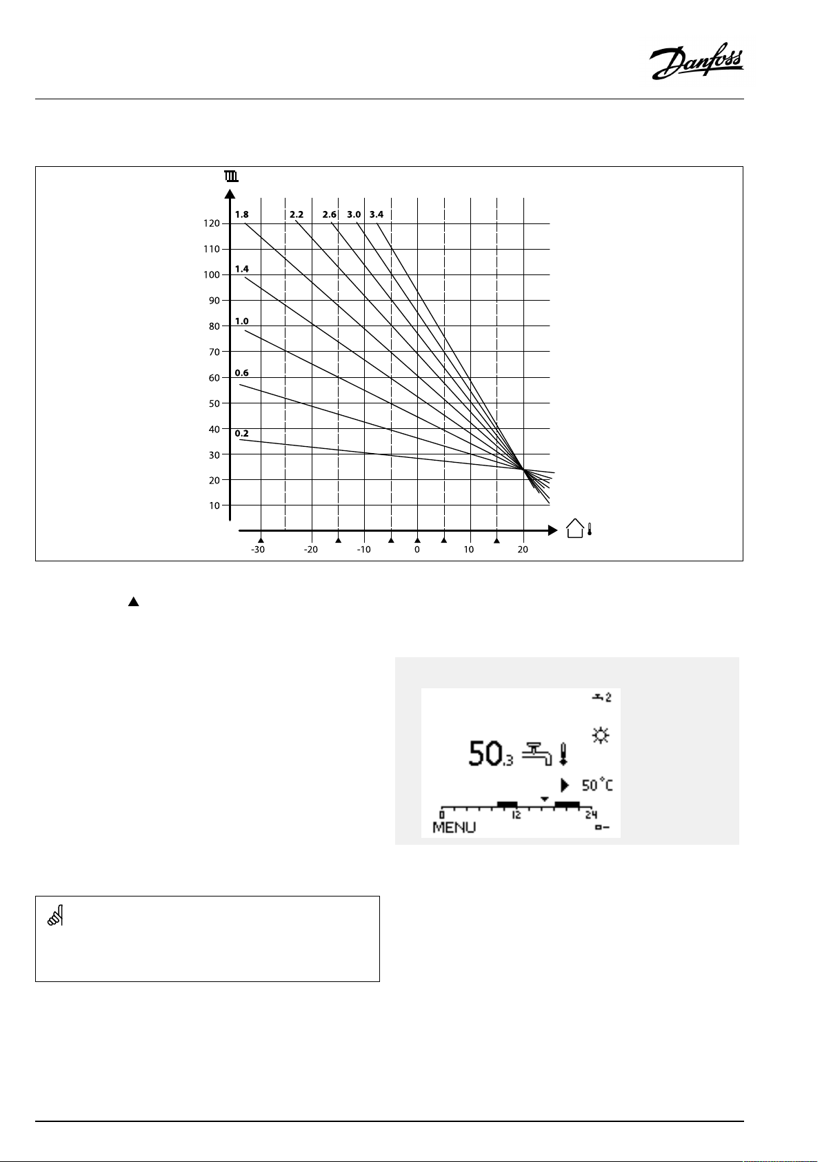
Choosingaheatcurveslope
Theheatcurvesrepresentthedesiredflowtemperatureatdifferentoutdoortemperaturesandatadesiredroomtemperatureof20°C.
Thesmallarrows()indicate6differentoutdoortemperaturevaluesatwhichyoucanchangetheheatcurve.
TheECLComfort210/296/310controlstheDHWtemperature
accordingtothedesiredflowtemperatureforexampleunderthe
influenceofthereturntemperature.
ActualDHWtemp.
ThedesiredDHWtemperatureissetintheoverviewdisplay.
50.3:
50:
ActualDHWtemperature
DesiredDHWtemperature
ParametersindicatedwithanIDno.like"1x607"meanauniversal
parameter.
xstandsforcircuit/parametergroup.
DesiredDHW
temp.
52|©Danfoss|2021.03
AQ005186455839en-010401
Page 53

OperatingGuideECLComfort310,applicationA367
MENU>Settings>Flowtemperature
DesiredT(Desiredflowtemperature)
WhentheECLComfortisinoverridemode,type"Const.T",thedesiredflow
temperaturecanbeset.
A"Const.T"relatedreturntemperaturelimitationcanalsobeset.SeeMENU
>Settings>Returnlimit>'Con.T,ret.Tlim. '
1x004
SeeAppendix“ParameterIDoverview”
MENU>Settings>Flowtemperature
Temp.min.
1x177
SeeAppendix“ParameterIDoverview”
Setthemin.flowtemperatureforthesystem.Thedesiredflow
temperaturewillnotbelowerthanthissetting.Adjustthefactory
setting,ifrequired.
Overridemode
WhenECLComfortisinScheduledmode,acontact(switch)signalcan
beappliedtoaninputinordertooverridetoComfort,Saving,Frost
ProtectionorConstanttemperature.Aslongasthecontact(switch)
signalisapplied,theoverrideisactive.
The"DesiredT"valuecanbeinfluencedby:
•temp.max.
•temp.min.
•roomtemp.limit
•returntemp.limit
•flow/powerlimit
‘Temp.min.’isoverruledif'Totalstop'isactiveinSavingmodeor
'Cut-out'isactive.
‘Temp.min.’canbeoverruledbytheinfluencefromthereturn
temperaturelimitation(see'Priority').
MENU>Settings>Flowtemperature
Temp.max.
1x178
SeeAppendix“ParameterIDoverview”
Setthemax.flowtemperatureforthesystem.Thedesired
temperaturewillnotbehigherthanthissetting.Adjustthefactory
setting,ifrequired.
Thesettingfor‘Temp.max. ’hashigherprioritythan‘Temp.min.’ .
Thesettingof‘heatcurve’ispossibleforheatingcircuitsonly.
Thesettingfor‘Temp.max. ’hashigherprioritythan‘Temp.min.’ .
AQ005186455839en-010401
©Danfoss|2021.03|53
Page 54

OperatingGuideECLComfort310,applicationA367
Externalsignalfordesiredflowtemperature
Avoltage(0-10V)canbeappliedtotheinputterminalS10in
ordertodeterminethedesiredflowtemperature.
ThemeasuredvoltageoninputS10mustbeconvertedtoa
temperaturevaluebythecontroller.Whenthevoltagegetshigher,
thedesiredflowtemperatureincreases.
Thefollowingsettingssetupthescaling.
MENU>Settings>Flowtemperature
Ext.desiredT—(ECLComfort310)
CircuitSettingrange
1
Theactualdesiredflowtemperatureisindicatedbytheunit°C.
Read-outonly
Factorysetting
Read-out:
--:
°C:
Externalvoltagesignalisnotconnected..
Externalvoltagesignalconvertedtodesiredflow
temperature.
Pushthedialtoseethegraphandenterthevaluesetsfortheinput
voltage(1and10volt)anddisplayeddesiredflowtemperature.
Example:Relationshipbetweeninputvoltageanddisplayeddesiredflow
temperature
Desiredflowtemp.(°C)
Volt
Thisexampleshowsthat1voltcorrespondsto10.0°Cand10volt
correspondto100°C.
Desiredflowtemperature:
10...120°C
Fixedvoltagesettings:1Vand10V
Factorysettings:
(1,10)and(10,100)
Thismeansthatthe‘Desiredflowtemperature’is10°Cat1.0V
and100°Cat10V.
Typically,thehigherthevoltage,thehigherthedisplayeddesired
flowtemperature.
Theexternalvoltagesignalmustbehigherthan1.0Vinorderto
activatetheoverride.
54|©Danfoss|2021.03
AQ005186455839en-010401
Page 55

OperatingGuideECLComfort310,applicationA367
5.3Roomlimit
ThefollowingsectionisageneraldescriptionforRoom
temperaturelimitation.
Thissectionisonlyrelevantifyouhaveinstalledaroom
temperaturesensororaRemoteControlUnitforutilizingtheroom
temperaturesignal.
Inthefollowingdescriptionisreferredto"flowtemperature"in
general.
Thecontrolleradjuststhedesiredflowtemperaturetocompensate
forthedifferencebetweenthedesiredandtheactualroom
temperature.
Iftheroomtemperatureishigherthanthedesiredvalue,the
desiredflowtemperaturecanbereduced.
The'Infl.-max.'(Influence,max.roomtemp.)determineshow
muchthedesiredflowtemperatureshouldbereduced.
Usethisinfluencetypetoavoidatoohighroomtemperature.
Thecontrollerwillallowforfreeheatgains,i.e.solarradiationor
heatfromafireplaceetc.
Iftheroomtemperatureislowerthanthedesiredvalue,thedesired
flowtemperaturecanbeincreased.
The'Infl.-min.'(Influence,min.roomtemperature)determines
howmuchthedesiredflowtemperatureshouldbeincreased.
Usethisinfluencetypetoavoidatoolowroomtemperature.
Thiscouldforexamplebecausedbywindysurroundings.
Atypicalsettingwillbe-4.0for'Infl.-max.'and4.0for'Infl.-min. '
ParametersindicatedwithanIDno.like"1x607"meanauniversal
parameter.
xstandsforcircuit/parametergroup.
MENU>Settings>Roomlimit
Adapt.time(adaptiontime)
Controlshowfasttheactualroomtemperatureadaptstothedesiredroom
temperature(Icontrol).
1x015
SeeAppendix“ParameterIDoverview”
OFF:
Thecontrolfunctionisnotinfluencedbythe'Adapt.
time'.
Minor
Thedesiredroomtemperatureisadaptedquickly.
value:
Major
Thedesiredroomtemperatureisadaptedslowly.
value:
Theadaptationfunctioncancorrectthedesiredroomtemperature
withmax.8Kxheatcurveslopevalue.
AQ005186455839en-010401
©Danfoss|2021.03|55
Page 56

OperatingGuideECLComfort310,applicationA367
MENU>Settings>Roomlimit
Infl.-max.(roomtemp.limitation,max.)
Determineshowmuchthedesiredflowtemperaturewillbeinfluenced
(decreased)iftheactualroomtemperatureishigherthanthedesiredroom
temperature(Pcontrol).
SeeAppendix“ParameterIDoverview”
0.0:
-2.0:
-5.0:
-9.9:
Noinfluence
Minorinfluence
Mediuminfluence
Maximuminfluence
1x182
=
X
#1#
#2#
#3#
Roomtemperature
=
Desiredroomtemperature
=
Negativeinfluence(1x082)whenactualroomtemp.getshigher
thandesiredroomtemp.
=
Positiveinfluence(1x083)whenactualroomtemp.getslowerthan
desiredroomtemp.
The‘Infl.-max.’and'Infl.-min. 'determinehowmuchtheroom
temperatureshouldinfluencethedesiredflowtemperature.
Ifthe‘Infl. ’factoristoohighand/orthe‘Adapt.time’toolow,thereis
ariskofunstablecontrol.
Example
Theactualroomtemperatureis2degreestoohigh.
The‘Infl.-max.’issetto-4.0.
Theheatcurveslopeis1.8(see'Heatcurve'in'Flowtemperature').
Result:
Thedesiredflowtemperatureischangedby(2x-4.0x1.8)
–14.4degrees.
MENU>Settings>Roomlimit
Infl.-min.(roomtemp.limitation,min.)
Determineshowmuchthedesiredflowtemperaturewillbeinfluenced
(increased)iftheactualroomtemperatureislowerthanthedesiredroom
temperature(Pcontrol).
SeeAppendix“ParameterIDoverview”
9.9:
5.0:
2.0:
0.0:
Maximuminfluence
Mediuminfluence
Minorinfluence
Noinfluence
Inapplicationsubtypes,whereaheatcurveslopevalueisnotpresent,
theheatcurveslopevalueissetto1:
Result:
Thedesiredflowtemperatureischangedby(2x-4.0x1):
–8.0degrees.
Example
1x183
Theactualroomtemperatureis2degreestoolow.
The‘Infl.-min.’issetto4.0.
Theheatcurveslopeis1.8(see'Heatcurve'in'Flowtemperature').
Result:
Thedesiredflowtemperatureischangedby(2x4.0x1.8)
14.4degrees.
Inapplicationsubtypes,whereaheatcurveslopevalueisnotpresent,
theheatcurveslopevalueissetto1:
Result:
Thedesiredflowtemperatureischangedby(2x4.0x1):
8.0degrees.
56|©Danfoss|2021.03
AQ005186455839en-010401
Page 57
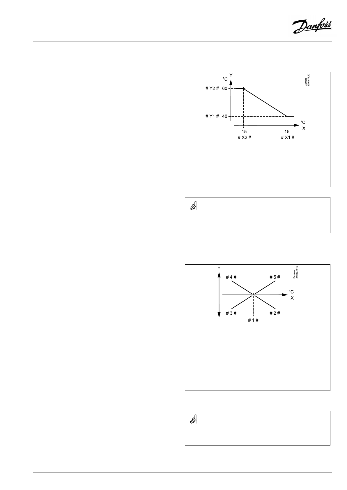
OperatingGuideECLComfort310,applicationA367
5.4Returnlimit
Thereturntemperaturelimitationisbasedontheoutdoor
temperature.Typicallyindistrictheatingsystemsahigherreturn
temperatureisacceptedatadecreaseinoutdoortemperature.The
relationshipbetweenthereturntemperaturelimitsandoutdoor
temperatureissetintwocoordinates.
Theoutdoortemperaturecoordinatesaresetin'HighToutX1'
and'LowToutX2' .Thereturntemperaturecoordinatesaresetin
'HighlimitY2'and'LowlimitY1' .
Thecontrollerautomaticallychangesthedesiredflowtemperature
toobtainanacceptablereturntemperaturewhenthereturn
temperaturefallsbeloworgetshigherthanthecalculatedlimit.
ThislimitationisbasedonaPIregulationwhereP('Infl.'factor)
respondsquicklytodeviationsandI('Adapt.time')responds
slowerandovertimeremovesthesmalloffsetsbetweenthe
desiredandactualvalues.Thisisdonebychangingthedesired
flowtemperature.
X
Y
#X1#
#X2#
#Y1#
#Y2#
=
Outdoortemperature
=
Limitationtemperature
=
HighTout(1x031)
=
LowTout(1x033)
=
Lowlimit(1x032)
=
Highlimit(1x034)
DHWcircuit
Thereturntemperaturelimitationisbasedonaconstant
temperaturevalue.
Thecontrollerautomaticallychangesthedesiredflowtemperature
toobtainanacceptablereturntemperaturewhenthereturn
temperaturefallsbeloworgetshigherthanthesetlimit.
ThislimitationisbasedonaPIregulationwhereP('Infl.'factor)
respondsquicklytodeviationsandI('Adapt.time')responds
slowerandovertimeremovesthesmalloffsetsbetweenthe
desiredandactualvalues.Thisisdonebychangingthedesired
flowtemperature.
Thecalculatedlimitisshowninbrackets()inthemonitoringdisplay.
Seethesection"Monitoringtemperaturesandsystemcomponents" .
=
X
#1#
#2#
#3#
#4#
#5#
Returntemperature
=
Limitationtemperature
Negativeinfluence(1x035)whenreturntemp.getshigherthan
=
limit.temp.
Negativeinfluence(1x036)whenreturntemp.getslowerthan
=
limit.temp.
Positiveinfluence(1x036)whenreturntemp.getslowerthanlimit.
=
temp.
Positiveinfluence(1x035)whenreturntemp.getshigherthan
=
limit.temp.
Ifthe‘Infl. ’factoristoohighand/orthe‘Adapt.time’toolow,thereis
ariskofunstablecontrol.
AQ005186455839en-010401
©Danfoss|2021.03|57
Page 58

OperatingGuideECLComfort310,applicationA367
Example,maximumreturntemperaturelimitation;
returntemperaturegetshigherthanlimit
=
T
Y
X
#1#
#2#
#3#
#4#
Temperature
=
Temperature
=
Time
=
Returntemperature
=
Returntemperaturelimit
=
Desiredflowtemperature
=
Actionpoint
58|©Danfoss|2021.03
AQ005186455839en-010401
Page 59

OperatingGuideECLComfort310,applicationA367
Example,minimumreturntemperaturelimitation;
returntemperaturegetslowerthanlimit
=
T
Y
X
#1#
#2#
#3#
#4#
Temperature
=
Temperature
=
Time
=
Returntemperature
=
Returntemperaturelimit
=
Desiredflowtemperature
=
Actionpoint
ParametersindicatedwithanIDno.like"1x607"meanauniversal
parameter.
xstandsforcircuit/parametergroup.
ThereturntemperaturelimitationfortheDHWcircuitisbasedonthe
settingin'Limit(returntemp.limitation)' .
Theinfluencefactorsaresetintheheatingcircuit.
Ifthereturntemperaturelimitationvalueintheheatingcircuitis
higherthanthereturntemperaturelimitationvalueintheDHWcircuit,
thehighestvalueisused.
AQ005186455839en-010401
©Danfoss|2021.03|59
Page 60

OperatingGuideECLComfort310,applicationA367
MENU>Settings>Returnlimit
Con.T,re.Tlim.(Constanttemperaturemode,return
temperaturelimitation)
The"Con.T ,ret.Tlimit"isthereturntemperaturelimitationvaluewhenthe
circuitissettooverridemodetype"Const.T"(=Constanttemperature).
1x028
SeeAppendix“ParameterIDoverview”
Value:Setthereturntemperaturelimitation
MENU>Settings>Returnlimit
Limit(returntemp.limitation)
Setthereturntemperaturevalueyouacceptforthesystem.
1x030
SeeAppendix“ParameterIDoverview”
Whenthereturntemperaturefallsbeloworgetshigherthanthe
setvalue,thecontrollerautomaticallychangesthedesiredflow/
ducttemperaturetoobtainanacceptablereturntemperature.The
influenceissetin'Infl.-max. 'and'Infl.-min.' .
MENU>Settings>Returnlimit
HighToutX1(returntemp.limitation,highlimit,X-axis)
Settheoutdoortemperaturevalueforthelowreturntemperaturelimitation.
SeeAppendix“ParameterIDoverview”
ThecorrespondingYcoordinateissetin'LowlimitY1' .
ThereturntemperaturelimitationfortheDHWcircuitisbasedonthe
settingin'Limit(returntemp.limitation)' .
Theinfluencefactorsaresetinheatingcircuit1.
Ifthereturntemperaturelimitationvalueinheatingcircuit1ishigher
thanthereturntemperaturelimitationvalueintheDHWcircuit,the
highestvalueisused.
1x031
60|©Danfoss|2021.03
AQ005186455839en-010401
Page 61
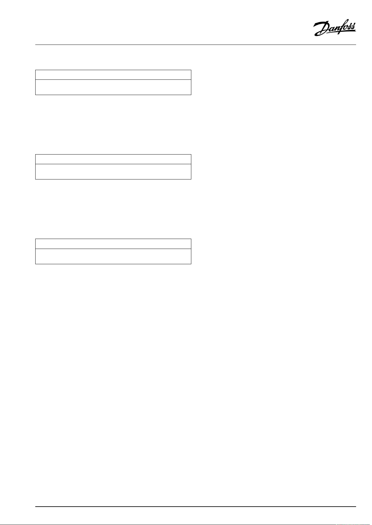
OperatingGuideECLComfort310,applicationA367
MENU>Settings>Returnlimit
LowlimitY1(returntemp.limitation,lowlimit,Y-axis)
Setthereturntemperaturelimitationreferringtotheoutdoortemperature
valuesetin'HighToutX1' .
SeeAppendix“ParameterIDoverview”
ThecorrespondingXcoordinateissetin'HighToutX1' .
MENU>Settings>Returnlimit
LowToutX2(returntemp.limitation,lowlimit,X-axis)
Settheoutdoortemperaturevalueforthehighreturntemperature
limitation.
SeeAppendix“ParameterIDoverview”
ThecorrespondingYcoordinateissetin'HighlimitY2'.
MENU>Settings>Returnlimit
HighlimitY2(returntemp.limitation,highlimit,Y-axis)
Setthereturntemperaturelimitationreferringtotheoutdoortemperature
valuesetin'LowToutX2' .
1x032
1x033
1x034
SeeAppendix“ParameterIDoverview”
ThecorrespondingXcoordinateissetin'LowToutX2' .
AQ005186455839en-010401
©Danfoss|2021.03|61
Page 62
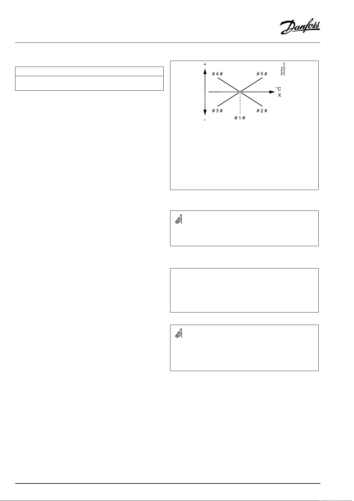
OperatingGuideECLComfort310,applicationA367
MENU>Settings>Returnlimit
Infl.-max.(returntemp.limitation-max.influence)
Determineshowmuchthedesiredflowtemperaturewillbeinfluencedifthe
returntemperatureishigherthanthecalculatedlimit.
SeeAppendix“ParameterIDoverview”
Influencehigherthan0:
Thedesiredflowtemperatureisincreased,whenthereturn
temperaturegetshigherthanthecalculatedlimit.
Influencelowerthan0:
Thedesiredflowtemperatureisdecreased,whenthereturn
temperaturegetshigherthanthecalculatedlimit.
1x035
=
X
#1#
#2#
#3#
#4#
#5#
Returntemperature
=
Limitationtemperature
Negativeinfluence(1x035)whenreturntemp.getshigherthan
=
limit.temp.
Negativeinfluence(1x036)whenreturntemp.getslowerthan
=
limit.temp.
Positiveinfluence(1x036)whenreturntemp.getslowerthanlimit.
=
temp.
Positiveinfluence(1x035)whenreturntemp.getshigherthan
=
limit.temp.
Ifthe‘Infl. ’factoristoohighand/orthe‘Adapt.time’toolow,thereis
ariskofunstablecontrol.
Example
Thereturnlimitisactiveabove50°C.
Theinfluenceissetto-2.0.
Theactualreturntemperatureis2degreestoohigh.
Result:
Thedesiredflowtemperatureischangedby-2.0x2=-4.0degrees.
Normally,thissettingislowerthan0indistrictheatingsystemsto
avoidatoohighreturntemperature.
Typically,thissettingis0inboilersystemsbecauseahigherreturn
temperatureisacceptable(seealso'Infl.-min. ').
62|©Danfoss|2021.03
AQ005186455839en-010401
Page 63
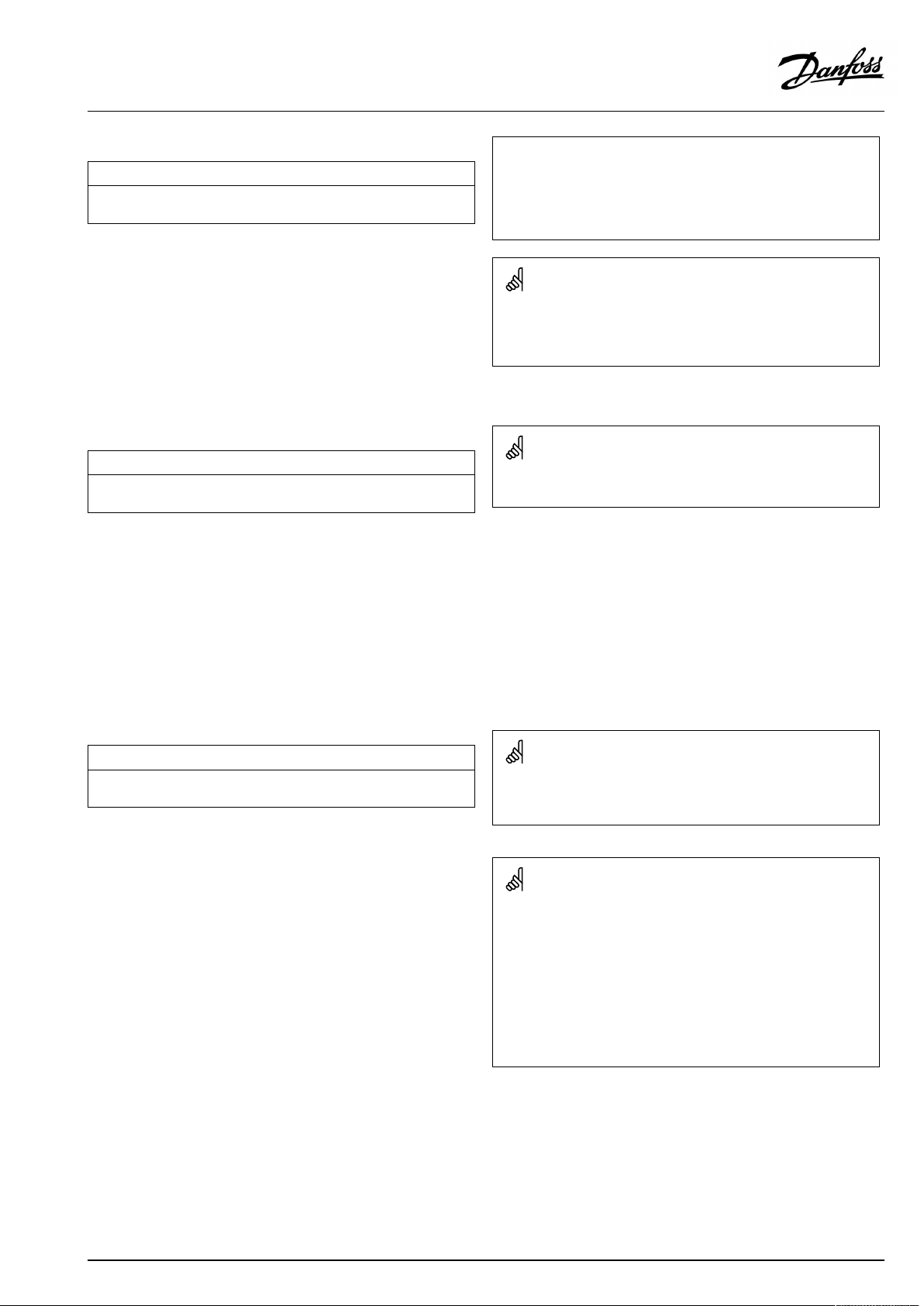
OperatingGuideECLComfort310,applicationA367
MENU>Settings>Returnlimit
Infl.-min.(returntemp.limitation-min.influence)
Determineshowmuchthedesiredflowtemperaturewillbeinfluencedifthe
returntemperatureislowerthanthecalculatedlimit.
SeeAppendix“ParameterIDoverview”
Influencehigherthan0:
Thedesiredflowtemperatureisincreased,whenthereturn
temperaturegetsbelowthecalculatedlimit.
Influencelowerthan0:
Thedesiredflowtemperatureisdecreased,whenthereturn
temperaturegetsbelowthecalculatedlimit.
MENU>Settings>Returnlimit
Adapt.time(adaptationtime)
Controlshowfastthereturntemperatureadaptstothedesiredreturn
temperaturelimit(Integrationcontrol).
SeeAppendix“ParameterIDoverview”
OFF:
Thecontrolfunctionisnotinfluencedbythe‘Adapt.
time’ .
Minor
Thedesiredtemperatureisadaptedquickly.
value:
Major
Thedesiredtemperatureisadaptedslowly.
value:
Example
1x036
1x037
Thereturnlimitisactivebelow50°C.
Theinfluenceissetto-3.0.
Theactualreturntemperatureis2degreestoolow.
Result:
Thedesiredflowtemperatureischangedby-3.0x2=-6.0degrees.
Normally,thissettingis0indistrictheatingsystemsbecausealower
returntemperatureisacceptable.
Typically,thissettingishigherthan0inboilersystemstoavoidatoo
lowreturntemperature(seealso'Infl.-max.').
Theadaptationfunctioncancorrectthedesiredflowtemperature
withmax.8K.
MENU>Settings>Returnlimit
Priority(priorityforreturntemp.limitation)
Choosewhetherthereturntemperaturelimitationshouldoverruletheset
min.flowtemperature‘Temp.min. ’.
SeeAppendix“ParameterIDoverview”
OFF:
ON:
Themin.flowtemperaturelimitisnotoverruled.
Themin.flowtemperaturelimitisoverruled.
1x085
IfyouhaveaDHWapplication:
Pleasealsosee‘Paralleloperation’(ID11043).
IfyouhaveaDHWapplication:
Whendependentparalleloperationisinfunction:
•Desiredflowtemperaturefortheheatingcircuitwillbeminimum
limited,when"Priorityforreturntemperature"(ID1x085)isset
toOFF.
•Desiredflowtemperaturefortheheatingcircuitwillnotbe
minimumlimited,when"Priorityforreturntemperature"
(ID1x085)issettoON.
AQ005186455839en-010401
©Danfoss|2021.03|63
Page 64

OperatingGuideECLComfort310,applicationA367
5.5Flow/powerlimit
Heatingcircuit
Afloworenergymetercanbeconnected(M-bussignal)totheECL
controllerinordertolimitthefloworconsumedpower.
Theflow/powerlimitationcanbebasedontheoutdoor
temperature.Typically,indistrictheatingsystemsahigherflowor
powerisacceptedatloweroutdoortemperatures.
Therelationshipbetweenthefloworpowerlimitsandtheoutdoor
temperatureissetintwocoordinates.
Theoutdoortemperaturecoordinatesaresetin'HighToutX1'
and'LowToutX2'.
Thefloworpowercoordinatesaresetin'LowlimitY1'and'High
limitY2' .Basedonthesesettings,thecontrollercalculatesthe
limitationvalue.
Whentheflow/powergetshigherthanthecalculatedlimit,the
controllergraduallyreducesthedesiredflowtemperaturetoobtain
anacceptablemax.floworpowerconsumption.
X
Y
#X1#
#X2#
#Y1#
#Y2#
=
Outdoortemperature
=
Limitation,floworpower
=
HighTout(1x119)
=
LowTout(1x118)
=
Lowlimit(1x117)
=
Highlimit(1x116)
=
X
Y
#1#
#2#
#3#
Ifthe‘Adapt.time’istoohigh,thereisariskofunstablecontrol.
Time
=
Floworpower
=
Floworpowerlimit
=
Actualfloworenergy
=
Desiredflowtemperature
64|©Danfoss|2021.03
AQ005186455839en-010401
Page 65

OperatingGuideECLComfort310,applicationA367
DHWcircuit
Afloworenergymetercanbeconnected(M-bussignal)totheECL
controllerinordertolimitthefloworconsumedpower.
Whentheflow/powergetshigherthanthesetlimit,thecontroller
graduallyreducesthedesiredflowtemperaturetoobtainan
acceptablemax.floworpowerconsumption.
=
X
Y
#1#
#2#
#3#
Time
=
Floworpower
=
Floworpowerlimit
=
Actualfloworenergy
=
Desiredflowtemperature
ParametersindicatedwithanIDno.like"1x607"meanauniversal
parameter.
xstandsforcircuit/parametergroup.
MENU>Settings>Flow/powerlimit
Limit(returntemp.limitation)
Setthereturntemperaturevalueyouacceptforthesystem.
1x030
SeeAppendix“ParameterIDoverview”
Whenthereturntemperaturefallsbeloworgetshigherthanthe
setvalue,thecontrollerautomaticallychangesthedesiredflow/
ducttemperaturetoobtainanacceptablereturntemperature.The
influenceissetin'Infl.-max. 'and'Infl.-min.' .
AQ005186455839en-010401
©Danfoss|2021.03|65
Page 66

OperatingGuideECLComfort310,applicationA367
MENU>Settings>Flow/powerlimit
Inputtype
Choiceofinputtypefromflow/energymeter
SeeAppendix“ParameterIDoverview”
OFF:
IM1-
Noinput
Flow/energymetersignalbasedonpulses.
IM5:
EM1-
Flow/energymetersignalfromM-bus.
EM5:
MENU>Settings>Flow/powerlimit
Actual(actualfloworpower)
Thevalueistheactualfloworpowerbasedonthesignalfromflow/energy
meter.
MENU>Settings>Flow/powerlimit
Limit(limitationvalue)
Thisvalueisinsomeapplicationsacalculatedlimitationvalue,basedonthe
actualoutdoortemperature.
Inotherapplicationsthevalueisaselectablelimitationvalue.
1x10⁹
ThesettingrangeforIMandEMdependsonchosensubtype.
1x111
SeeAppendix“ParameterIDoverview”
MENU>Settings>Flow/powerlimit
Adapt.time(adaptationtime)
Controlshowfasttheflow/powerlimitationadaptstothedesired
limitation.
SeeAppendix“ParameterIDoverview”
OFF:
Thecontrolfunctionisnotinfluencedbythe‘Adapt.
time’ .
Minor
Thedesiredtemperatureisadaptedquickly.
value:
Major
Thedesiredtemperatureisadaptedslowly.
value:
1x112
Ifthe‘Adapt.time’istoolow,thereisariskofunstablecontrol.
66|©Danfoss|2021.03
AQ005186455839en-010401
Page 67

OperatingGuideECLComfort310,applicationA367
MENU>Settings>Flow/powerlimit
Filterconstant
Thevalueofthefilterconstantdeterminesthedampeningofthemeasured
value.
Thehigherthevalue,themoredampening.
Bythis,atooquickchangeofthemeasuredvaluecanbeavoided.
SeeAppendix“ParameterIDoverview”
Minor
Lowerdampening
value:
Major
Higherdampening
value:
MENU>Settings>Flow/powerlimit
Units
Choiceofunitsformeasuredvalues.
SeeAppendix“ParameterIDoverview”
Flowvaluesareexpressedasl/horm³/h
PowervaluesareexpressedaskW,MWorGW.
1x113
1x115
Listforsettingrangeof'Units':
l/h
m³/h
kW
MW
GW
MENU>Settings>Flow/powerlimit
HighlimitY2(flow/powerlimitation,highlimit,Y-axis)
Settheflow/powerlimitationreferringtotheoutdoortemperatureset
in'LowToutX2' .
SeeAppendix“ParameterIDoverview”
ThecorrespondingXcoordinateissetin'LowToutX2' .
MENU>Settings>Flow/powerlimit
LowlimitY1(flow/powerlimitation,lowlimit,Y-axis)
Settheflow/powerlimitationreferringtotheoutdoortemperaturesetin
'HighToutX1' .
SeeAppendix“ParameterIDoverview”
ThecorrespondingXcoordinateissetin'HighToutX1' .
1x116
1x117
Thelimitationfunctioncanoverruletheset'Temp.min'ofthedesired
flowtemperature.
AQ005186455839en-010401
©Danfoss|2021.03|67
Page 68

OperatingGuideECLComfort310,applicationA367
MENU>Settings>Flow/powerlimit
LowToutX2(flow/powerlimitation,lowlimit,X-axis)
Settheoutdoortemperaturevalueforthehighflow/powerlimitation.
SeeAppendix“ParameterIDoverview”
ThecorrespondingYcoordinateissetin'HighlimitY2'.
MENU>Settings>Flow/powerlimit
HighToutX1(flow/powerlimitation,highlimit,X-axis)
Settheoutdoortemperaturevalueforthelowflow/powerlimitation.
SeeAppendix“ParameterIDoverview”
ThecorrespondingYcoordinateissetin'LowlimitY1' .
1x118
1x119
68|©Danfoss|2021.03
AQ005186455839en-010401
Page 69

OperatingGuideECLComfort310,applicationA367
5.6Optimization
Thesection"Optimization"describesspecificapplicationrelated
issues.
Theparameters'Autosaving' ,'Boost','Optimizer','Totalstop'areall
relatedtoheatingmodeonly.
'Summer,cut-out'determine,atrisingoutdoortemperature,the
stopofheating.
ParametersindicatedwithanIDno.like"1x607"meanauniversal
parameter.
xstandsforcircuit/parametergroup.
AQ005186455839en-010401
©Danfoss|2021.03|69
Page 70
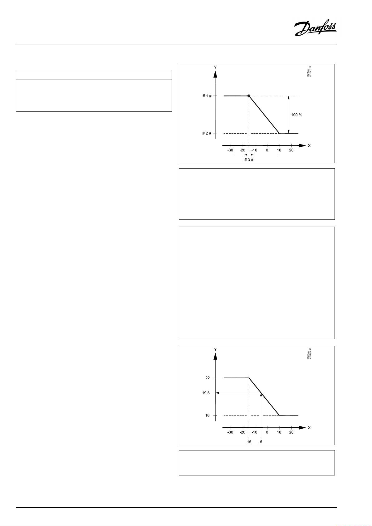
OperatingGuideECLComfort310,applicationA367
MENU>Settings>Optimization
Autosaving(savingtemp.dependentonoutdoortemp.)
Belowthesetvaluefortheoutdoortemperature,thesavingtemperature
settinghasnoinfluence.Abovethesetvaluefortheoutdoortemperature,
thesavingtemperaturerelatestotheactualoutdoortemperature.The
functionisrelevantindistrictheatinginstallationsinordertoavoidabig
changeinthedesiredflowtemperatureafterasavingperiod.
SeeAppendix“ParameterIDoverview”
OFF:
Thesavingtemperaturedoesnotdependonthe
outdoortemperature;thereductionis100%.
Value:Thesavingtemperaturedependsontheoutdoor
temperature.Whentheoutdoortemperatureisabove
10°C,thereductionis100%.Thelowertheoutdoor
temperature,thelessthetemperaturereduction.
Belowthesetvalue,thesavingtemperaturesetting
hasnoinfluence.
Comforttemperature:
Thedesiredroomtemperaturein
Comfortmode
Savingtemperature:
ThedesiredroomtemperatureinSaving
mode
ThedesiredroomtemperaturesforComfortandSavingmodes
aresetinthedisplayoverviews.
1x011
=
X
Y
#1#
#2#
#3#
Example:
Actualoutdoortemperature(T.out):
DesiredroomtemperaturesettinginComfortmode:
DesiredroomtemperaturesettinginSavingmode:
Settingin‘Autosaving’:
Outdoortemperature(°C)
=
Desiredroomtemperature(°C)
=
Desiredroomtemperature(°C),Comfortmode
=
Desiredroomtemperature(°C),Savingmode
=
Autosavingtemperature(°C),ID11011
–5°C
22°C
16°C
–15°C
Theconditionfortheoutdoortemperatureinfluence:
T.out.influence=(10-T.out)/(10-setting)=
(10-(-5))/(10-(-15))=
15/25=0,6
ThecorrecteddesiredroomtemperatureinSavingmode:
T.room.ref.Saving+(T.out.influencex(T.room.ref.ComfortT.room.ref.Saving))
16+(0,6x(22-16))=19,6°C
=
X
Y
Outdoortemperature(°C)
=
Desiredroomtemperature(°C)
70|©Danfoss|2021.03
AQ005186455839en-010401
Page 71

OperatingGuideECLComfort310,applicationA367
MENU>Settings>Optimization
Boost
Shortenstheheating-upperiodbyincreasingthedesiredflowtemperature
bythepercentageyouset.
SeeAppendix“ParameterIDoverview”
OFF:
Value:
Theboostfunctionisnotactive.
Thedesiredflowtemperatureisincreasedtemporarily
withthesetpercentage.
Inordertoshortentheheating-upperiodafterasaving
temperatureperiod,thedesiredflowtemperaturecanbeincreased
temporarily(max.1hour).Atoptimizingtheboostisactiveinthe
optimizationperiod('Optimizer').
IfaroomtemperaturesensororanECA30/31isconnected,the
booststopswhentheroomtemperatureisreached.
MENU>Settings>Optimization
Ramp(referenceramping)
Thetime(minutes)inwhichthedesiredflowtemperatureincreases
graduallytoavoidloadpeaksintheheatsupply.
SeeAppendix“ParameterIDoverview”
1x012
1x013
OFF:
Value:
Therampingfunctionisnotactive.
Thedesiredflowtemperatureisincreasedgraduallywith
thesetminutes.
Inordertoavoidloadpeaksinthesupplynetwork,theflow
temperaturecanbesettoincreasegraduallyafteraperiodwith
savingtemperature.Thiscausesthevalvetoopengradually.
X
Y
#1#
=
Time
=
Desiredflowtemperature
=
Rampingtime
=
Comforttemperature
=
Savingtemperature
AQ005186455839en-010401
©Danfoss|2021.03|71
Page 72

OperatingGuideECLComfort310,applicationA367
MENU>Settings>Optimization
Optimizer(optimizingtimeconstant)
Optimizesthestartandstoptimesforthecomforttemperatureperiodto
obtainthebestcomfortatthelowestenergyconsumption.
Thelowertheoutdoortemperature,theearliertheheatingcut-in.Thelower
theoutdoortemperature,thelatertheheatingcut-out.
Theoptimizedheatingcut-outtimecanbeautomaticordisabled.The
calculatedstartandstoptimesarebasedonthesettingoftheoptimizing
timeconstant.
SeeAppendix“ParameterIDoverview”
Adjusttheoptimizingtimeconstant.
Thevalueconsistsofatwodigitnumber.Thetwodigitshavethe
followingmeaning(digit1=TableI,digit2=TableII).
OFF:
Nooptimization.Theheatingstartsandstopsatthe
timessetintheschedule.
10...59:
SeetablesIandII.
TableI:
1x014
Systemtype
LeftdigitHeataccumulationofthe
building
Radiator
1-light
systems
2-medium
3-heavy
Floorheating
4-medium
systems
5-heavy
TableII:
RightdigitDimensioningtemperatureCapacity
-0-50°Clarge
-1
-45°C
-5
-25°C
normal
MENU>Settings>Optimization
Basedon(optimizationbasedonroom/outdoortemp.)
Theoptimizedstartandstoptimecanbebasedoneitherroomoroutdoor
temperature.
SeeAppendix“ParameterIDoverview”
OUT:
Optimizationbasedonoutdoortemperature.Usethis
settingiftheroomtemperatureisnotmeasured.
ROOM:
Optimizationbasedonroomtemperature,ifmeasured.
-9
Dimensioningtemperature:
Thelowestoutdoortemperature(usuallydeterminedbyyoursystem
designerinconnectionwiththedesignoftheheatingsystem)atwhich
theheatingsystemcanmaintainthedesignedroomtemperature.
Example
Thesystemtypeisradiator,andtheheataccumulationofthebuilding
ismedium.
Theleftdigitis2.
Thedimensioningtemperatureis-25°C,andthecapacityisnormal.
Therightdigitis5.
Result:
Thesettingistobechangedto25.
1x020
-5°C
small
72|©Danfoss|2021.03
AQ005186455839en-010401
Page 73

OperatingGuideECLComfort310,applicationA367
MENU>Settings>Optimization
Totalstop
Decidewhetheryouwantatotalstopduringthesavingtemperatureperiod.
1x021
SeeAppendix“ParameterIDoverview”
OFF:
Nototalstop.Thedesiredflowtemperatureisreduced
accordingto:
•desiredroomtemperatureinsavingmode
•autosaving
ON:
Thedesiredflowtemperatureisloweredtothesetvalue
in‘Frostpr. ’Thecirculationpumpisstoppedbutfrost
protectionisstillactive,see'PfrostT' .
Totalstop=OFF
Totalstop=ON
X
Y
=
Time
=
Desiredflowtemperature
=
Comforttemperature
=
Savingtemperature
=
Frostprotection
MENU>Settings>Optimization
Pre-stop(optimizedstoptime)
Disabletheoptimizedstoptime.
SeeAppendix“ParameterIDoverview”
OFF:
ON:
Theoptimizedstoptimeisdisabled.
Theoptimizedstoptimeisenabled.
Themin.flowtemperaturelimitation('Temp.min.')isoverruledwhen
'Totalstop'isON.
1x026
Example:OptimizationofComfortfrom07:00-22:00
=
X
#1#
#2#
#3#
#4#
#5#
Time
=
Schedule
=
Prestop=OFF
=
Prestop=ON
=
Optimizedstart
=
Optimizedstop
AQ005186455839en-010401
©Danfoss|2021.03|73
Page 74
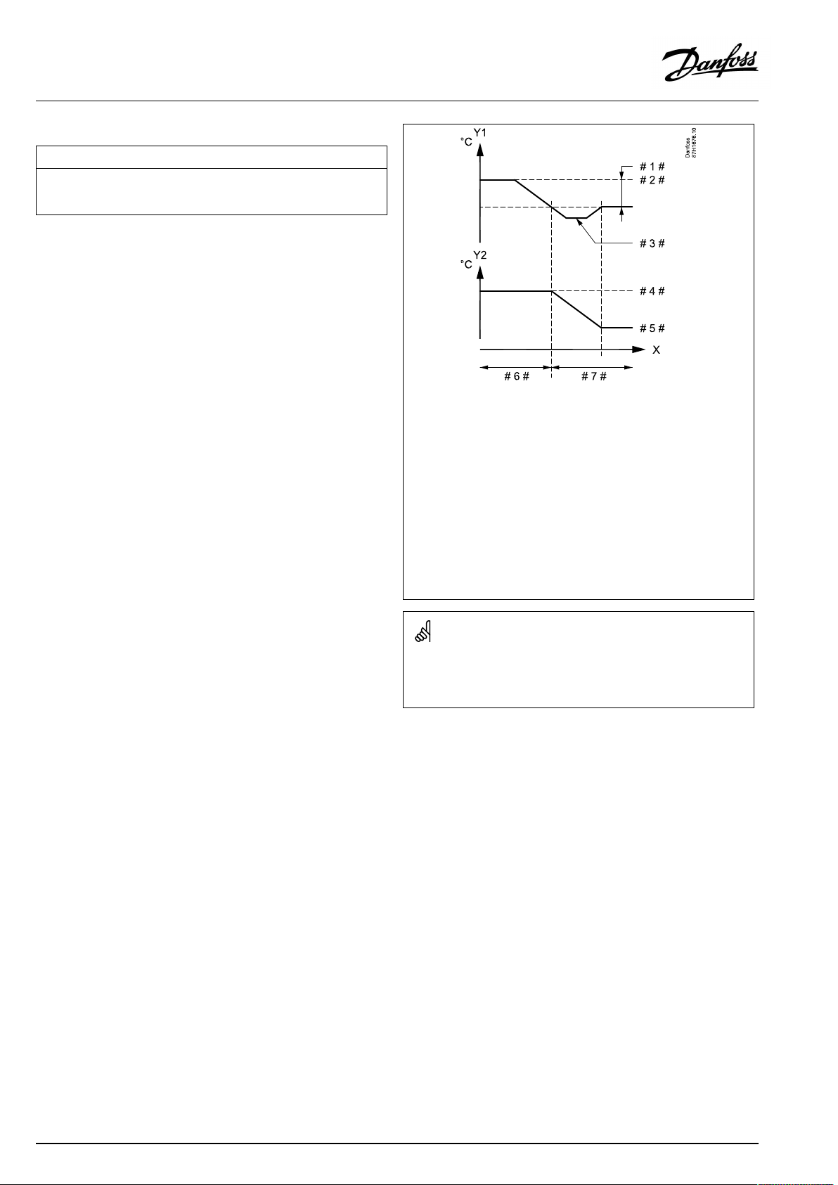
OperatingGuideECLComfort310,applicationA367
MENU>Settings>Optimization
Paralleloperation
ChoosewhethertheheatingcircuitistooperateindependenceoftheDHW
circuit.Thisfunctionmightbeusefulifaninstallationhaslimitedpower
orflow.
SeeAppendix“ParameterIDoverview”
OFF:
Independentparalleloperation,i.e.theDHWand
theheatingcircuitsoperateindependentlyofeach
other.ItmakesnodifferencewhetherthedesiredDHW
temperaturecanbereachedornot.
Value:Dependentparalleloperation,i.e.thedesiredheating
temperaturedependsontheDHWdemand.Choose
howmuchtheDHWtemperaturecandropbeforethe
desiredheatingtemperaturehastobedecreased.
1x043
=
X
Y1
Y2
#1#
#2#
#3#
#4#
#5#
#6#
#7#
Time
=
Temperature
=
Temperature
=
Acceptabledeviation(Paralleloperation,1x043)
=
DesiredDHWtemperature
=
ActualDHWtemperature
=
Desiredheatingtemperature
=
Reducedheatingtemperature
=
100%paralleloperation
=
Paralleloperationwithdecreasedheatingtemperature
IftheactualDHWtemperaturedeviatesmorethanthesetvalue,the
gearmotorM2intheheatingcircuitwillgraduallyclosetosuchan
extentthattheDHWtemperaturestabilizesatthelowestacceptable
value.
74|©Danfoss|2021.03
AQ005186455839en-010401
Page 75

OperatingGuideECLComfort310,applicationA367
MENU>Settings>Optimization
Summer,cut-out(limitforheatingcut-out)
1x179
SeeAppendix“ParameterIDoverview”
TheheatingcanbeswitchedOFFwhentheoutdoortemperatureis
higherthanthesetvalue.Thevalveclosesandafterthepost-run
time,theheatingcirculationpumpstops.‘Temp.min.’willbe
overruled.
TheheatingsystemswitchesONagainwhentheoutdoor
temperatureandtheaccumulated(filtered)outdoortemperature
becomelowerthanthesetlimit.
Thisfunctioncansaveenergy.
Setthevalueforoutdoortemperatureatwhichyouwantthe
heatingsystemtoswitchOFF .
Summer,cut-out
=
X
Y
#1#
#2#
#3#
#4#
#5#
Time
=
Temperature
=
Actualoutdoortemperature
=
Cut-outtemperature(1x179)
=
Accummulated(filtered)outdoortemperature
=
Heatingenabled
=
Heatingdisabled
Theheatingcut-outisonlyactivewhenthecontrollermodeisin
scheduledoperation.Whenthecut-outvalueissettoOFF,thereis
noheatingcut-out.
AQ005186455839en-010401
©Danfoss|2021.03|75
Page 76

OperatingGuideECLComfort310,applicationA367
5.7Controlparameters
Controlofvalves
Themotorizedcontrolvalvesarecontrolledbymeansof3-point
controlsignal.
Valvecontrol:
Themotorizedcontrolvalveisopenedgraduallywhentheflow
temperatureislowerthanthedesiredflowtemperatureandvice
versa.
Thewaterflowthroughthecontrolvalveismanagedbymeans
ofanelectricactuator.Thecombination"actuator"and"control
valve"isalsocalledmotorizedcontrolvalve.Theactuatorcanin
thiswaygraduallyincreaseordecreasetheflowinordertochange
thesuppliedenergy.Differenttypesofactuatorsareavailable.
3-pointcontrolledactuator:
Theelectricactuatorcontainsareversiblegear-motor.Electric
"open"and"close"signalscomefromtheelectronicoutputsofthe
ECLComfortcontrollerinordertomanagethecontrolvalve.The
signalsareintheECLComfortcontrollerexpressedas"Arrow-up"
(open)and"Arrow-down"(close)anddisplayedatthevalvesymbol.
Whentheflowtemperature(forexampleatS3)islowerthanthe
desiredflowtemperature,shortopen-signalscomefromtheECL
Comfortcontrollerinordertograduallyincreasetheflow.Bythis,
theflowtemperaturewillalignwiththedesiredtemperature.
Oppositely,whentheflowtemperatureishigherthanthedesired
flowtemperature,shortclose-signalscomefromtheECLComfort
controllerinordertograduallyreducetheflow.Again,theflow
temperaturealignswiththedesiredtemperature.
Neitheropen-signalsnorclose-signalswillcomeaslongastheflow
temperaturecorrespondstothedesiredtemperature.
76|©Danfoss|2021.03
AQ005186455839en-010401
Page 77
OperatingGuideECLComfort310,applicationA367
Thermo-hydraulicactuator,ABV
Danfossthermo-actuatortypeABVisaslowactingvalveactuator.
InsidetheABVanelectricheatcoilwillheatathermostaticelement
whenanelectricsignalisapplied.Whenheatingthethermostatic
elementitexpandsinordertomanagethecontrolvalve.
Twobasictypesareavailable:ABVNC(NormalClosed)andABVNO
(normalopen).Forexample,ABVNCkeepsa2-portcontrolvalve
closedwhennoopen-signalsareapplied.
Electricopen-signalscomefromtheelectronicoutputoftheECL
Comfortcontrollerinordertomanagethecontrolvalve.When
open-signalsareappliedtotheABVNC,thevalvegraduallyopens.
Open-signalsareintheECLComfortcontrollerexpressedas
"Arrow-up"(open)anddisplayedatthevalvesymbol.
Whentheflowtemperature(forexampleatS3)islowerthanthe
desiredflowtemperature,relativelylongopen-signalscomefrom
theECLComfortcontrollerinordertoincreasetheflow.Bythis,
theflowtemperaturewillovertimebealignedwiththedesired
temperature.
Oppositely,whentheflowtemperatureishigherthanthedesired
flowtemperature,relativelyshortopen-signalscomefromtheECL
Comfortcontrollerinordertoreducetheflow.Again,theflow
temperaturealigns,overtime,withthedesiredtemperature.
ThecontroloftheDanfossthermo-actuatortypeABVusesaunique
designedalgorithmandisbasedonthePWMprinciple(Pulse
WidthModulation),wherethedurationofthepulsedetermines
themanagementofthecontrolvalve.Thepulsesarerepeated
each10sec.
Aslongastheflowtemperaturecorrespondstothedesired
temperature,thedurationoftheopen-signalswillremainconstant.
ParametersindicatedwithanIDno.like"1x607"meanauniversal
parameter.
xstandsforcircuit/parametergroup.
MENU>Settings>Controlparameters
Actuator
ABV/GEAR
1x024
GEAR
Selectionofvalveactuatortype.
Whenselecting"ABV",thecontrolparameters:
•Motorprotection(ID1x174)
ABV:
GEAR:
AQ005186455839en-010401
DanfosstypeABV(thermoactuator).
Gearmotorbasedactuator.
•Xp(ID1x184)
•Tn(ID1x185)
•Mrun(ID1x186)
•Nz(ID1x187)
•Min.act.time(ID1x189)
arenotconsidered.
©Danfoss|2021.03|77
Page 78

OperatingGuideECLComfort310,applicationA367
MENU>Settings>Controlparameters
Motorpr.(motorprotection)
Preventsthecontrollerfromunstabletemperaturecontrol(andresulting
actuatoroscillations).Thiscanoccuratverylowload.Themotorprotection
increasesthelifetimeofallinvolvedcomponents.
SeeAppendix“ParameterIDoverview”
OFF:
Value:
Motorprotectionisnotactivated.
Motorprotectionisactivatedafterthesetactivation
delayinminutes.
MENU>Settings>Controlparameters
Xp(proportionalband)
SeeAppendix“ParameterIDoverview”
Settheproportionalband.Ahighervaluewillresultinastablebut
slowcontroloftheflowtemperature.
MENU>Settings>Controlparameters
Tn(integrationtimeconstant)
1x174
Recommendedforductsystemswithvariableload.
1x184
1x185
SeeAppendix“ParameterIDoverview”
Setahighintegrationtimeconstant(inseconds)toobtainaslow
butstablereactiontodeviations.
Alowintegrationtimeconstantwillmakethecontrollerreactfast
butwithlessstability.
MENU>Settings>Controlparameters
Mrun(runningtimeofthemotorizedcontrolvalve)
‘Mrun’isthetimeinsecondsittakesthecontrolledcomponenttomove
fromfullyclosedtofullyopenposition.
SeeAppendix“ParameterIDoverview”
Setthe‘Mrun’accordingtotheexamplesormeasuretherunning
timebymeansofastopwatch.
1x186
Howtocalculatetherunningtimeofamotorizedcontrolvalve
Therunningtimeofthemotorizedcontrolvalveiscalculatedusing
thefollowingmethods:
Seatedvalves
Runningtime=
Example:
Rotatingvalves
Runningtime=
Example:90degr.x2sec./degr.=180sec.
Valvestroke(mm)xactuatorspeed(sec./mm)
5.0mmx15sec./mm=75sec.
Turningdegreesxactuatorspeed(sec./degr.)
78|©Danfoss|2021.03
AQ005186455839en-010401
Page 79
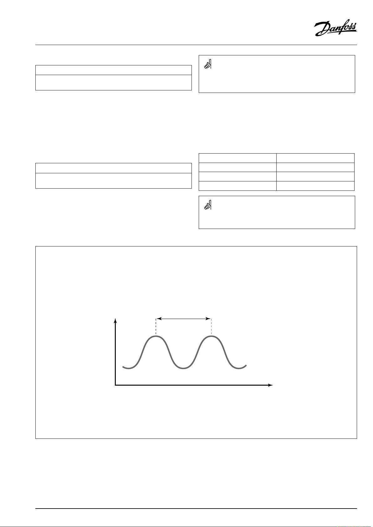
OperatingGuideECLComfort310,applicationA367
MENU>Settings>Controlparameters
Nz(neutralzone)
Whentheactualflowtemperatureiswithintheneutralzone,thecontroller
doesnotactivatethemotorizedcontrolvalve.
SeeAppendix“ParameterIDoverview”
Settheacceptableflowtemperaturedeviation.
Settheneutralzonetoahighvalueifyoucanacceptahigh
variationinflowtemperature.
MENU>Settings>Controlparameters
Min.act.time(min.activationtimegearmotor)
Themin.pulseperiodof20ms(milliseconds)foractivationofthegear
motor.
SeeAppendix“ParameterIDoverview”
1x187
Theneutralzoneissymmetricalaroundthedesiredflowtemperature
value,i.e.halfthevalueisaboveandhalfthevalueisbelowthis
temperature.
SettingexampleValuex20ms
1x189
240ms
10200ms
501000ms
Thesettingshouldbekeptashighasacceptabletoincreasethe
lifetimeoftheactuator(gearmotor).
IfyouwanttotunethePIregulationprecisely,youcanusethefollowingmethod:
•Setthe‘Tn’(integrationtimeconstant)toitsmax.value(999sec.).
•Decreasethevalueforthe‘Xp’(proportionalband)untilthesystemstartshunting(i.e.getsunstable)withaconstantamplitude(it
mightbenecessarytoforcethesystembysettinganextremelowvalue).
•Findthecriticaltimeperiodonthetemperaturerecorderoruseastopwatch.
Temp.
Criticaltimeperiod
Time
Thiscriticaltimeperiodwillbecharacteristicforthesystem,andyoucanevaluatethesettingsfromthiscriticalperiod.
‘Tn’=
0.85xcriticaltimeperiod
‘Xp’=
2.2xproportionalbandvalueinthecriticaltimeperiod
Iftheregulationseemstobetooslow,youcandecreasetheproportionalbandvalueby10%.Makesurethereisaconsumption
whenyousettheparameters.
AQ005186455839en-010401
©Danfoss|2021.03|79
Page 80

OperatingGuideECLComfort310,applicationA367
5.8Application
Thesection"Application"describesspecificapplicationrelated
issues.
Someoftheparameterdescriptionsareuniversalfordifferent
applicationkeys.
ParametersindicatedwithanIDno.like"1x607"meanauniversal
parameter.
xstandsforcircuit/parametergroup.
MENU>Settings>Application
ECAaddr.(ECAaddress,choiceofRemoteControlUnit)
Decidestheroomtemperaturesignaltransferandcommunicationwiththe
RemoteControlUnit.
SeeAppendix“ParameterIDoverview”
OFF:
NoRemoteControlUnit.Onlyroomtemperaturesensor,
ifany.
A:
B:
RemoteControlUnitECA30/31withaddressA.
RemoteControlUnitECA30/31withaddressB.
MENU>Settings>Application
Demandoffset
Thedesiredflowtemperatureinheatingcircuit1canbeinfluencedbythe
demandforadesiredflowtemperaturefromanothercontroller(slave)or
anothercircuit.
SeeAppendix“ParameterIDoverview”
OFF:
Thedesiredflowtemperatureincircuit1isnot
influencedbythedemandofanyothercontroller(slave
orcircuit2).
Value:
Thedesiredflowtemperatureisincreasedbytheset
valuein‘Demandoffset’ ,ifthedemandoftheslave/
circuit2ishigher.
1x010
TheRemoteControlUnitmustbesetaccordingly(AorB).
Temp.
1x017
Settingin
‘Demandoffset’
Des.flowtemp.,
circuit1
Des.flowtemp.,
circuit2
Time
80|©Danfoss|2021.03
Thefunctionof‘Demandoffset’cancompensateforheatlosses
betweenmasterandslavecontrolledsystems.
Whensetting"Demandoffset"toavalue,thereturntemperature
limitationwillreactaccordingtothehighestlimitationvalue(Heating
/DHW).
AQ005186455839en-010401
Page 81

OperatingGuideECLComfort310,applicationA367
MENU>Settings>Application
Pexercise(pumpexercise)
Exercisesthepumptoavoidblockinginperiodswithoutheatdemand.
SeeAppendix“ParameterIDoverview”
OFF:
ON:
Thepumpexerciseisnotactive.
ThepumpisswitchedONfor1minuteeverythirddayat
noon(12:14hours).
MENU>Settings>Application
Mexercise(valveexercise)
Exercisesthevalvetoavoidblockinginperiodswithoutheatdemand.
SeeAppendix“ParameterIDoverview”
OFF:
ON:
Thevalveexerciseisnotactive.
Thevalveopensfor7minutesandclosesfor7minutes
everythirddayatnoon(12:00hours).
MENU>Settings>Application
1x022
1x023
Ppost-run
Heatingapplications:
ThecirculationpumpintheheatingcircuitcanbeONforanumberof
minutes(m)afterheatingstop.Heatingstopiswhenthedesiredflow
temperaturegetslowerthanthesettingin'PheatT'(IDno.1x078).
Coolingapplications:
ThecirculationpumpinthecoolingcircuitcanbeONforanumberof
minutes(m)aftercoolingstop.Coolingstopiswhenthedesiredflow
temperaturegetshigherthanthesettingin'PcoolT'(IDno.1x070).
ThisPpost-runfunctioncanutilizetheremainingenergyinforexamplea
heatexchanger.
SeeAppendix“ParameterIDoverview”
0:
Thecirculationpumpstopsimmediatelyafterheating
orcoolingstop.
Value:
ThecirculationpumpisONforthesettimeafterheating
orcoolingstop.
MENU>Settings>Application
DHWPpost-run(DHWpump,post-run)
SettheDHWpumppost-runtime(minutes).TheDHWpumpcancontinue
tobeswitchedONaftertheDHWheatingprocedureinordertoutilizethe
remainingheatintheheatexchanger/boiler.
1x040
1x041
SeeAppendix“ParameterIDoverview”
Value:
Setthenumberofminutesforthepost-run.
AQ005186455839en-010401
©Danfoss|2021.03|81
Page 82

OperatingGuideECLComfort310,applicationA367
MENU>Settings>Application
Char.Ppost-run(DHWchargingpump,post-run)
SettheDHWchargingpumppost-runtime(minutes).TheDHWcharging
pumpcancontinuetobeswitchedONaftertheDHWheatingprocedurein
ordertoutilizetheremainingheatintheheatexchanger.
SeeAppendix“ParameterIDoverview”
Value:
Setthenumberofminutesforthepost-run.
MENU>Settings>Application
Max.DHWtime
SetthemaxDHWheatingtime(minutes).WhenDHWheatingisactiveand
theset'Max.DHWtime'expires,DHWheatingisdeactivated.
SeeAppendix“ParameterIDoverview”
OFF:
IftheDHWtemperatureislowerthantheDHWcharging
cut-intemperature,theDHWchargingremainsactive
forunlimitedperiodoftime.IftheDHWtemperatureis
higherthantheDHWchargingcut-intemperature,the
chargingisdeactivatedafter35minutes.
Value:
TheDHWheating/chargingisdeactivatedwhentheset
'Max.DHWtime'(inminutes)expires.
1x042
1x044
MENU>Settings>Application
DHWdeact.time(DHWdeactivationtime)
Setthetime(minutes)thatmustelapseafteraDHWheatingperiodbeforea
newDHWheatingperiodcanbestarted.
1x045
SeeAppendix“ParameterIDoverview”
Value:WhentheDHWheating/chargingtimehasreachedits
maximum,DHWcanonlybeheated/chargedagain
afterthesetdeactivationtime(inminutes)hasexpired.
82|©Danfoss|2021.03
AQ005186455839en-010401
Page 83
OperatingGuideECLComfort310,applicationA367
MENU>Settings>Application
Pdemand
Thecirculationpumpinthemastercircuitcanbecontrolledinrelationto
themastercircuit'sdemandorslavecircuit'sdemand.
SeeAppendix“ParameterIDoverview”
Heatingapplications:
OFF:
ThecirculationpumpisONwhenthedesiredflow
temperatureintheheatingcircuitishigherthanthe
valuesetin'PheatT'.
ON:
ThecirculationpumpisONwhenthedesiredflow
temperaturefromslavesishigherthanthevaluesetin
'PheatT'.
Coolingapplications:
OFF:
ThecirculationpumpisONwhenthedesiredflow
temperatureinthecoolingcircuitislowerthanthevalue
setin'PcoolT'.
ON:
ThecirculationpumpisONwhenthedesiredflow
temperaturefromslavesislowerthanthevaluesetin
'PcoolT'.
MENU>Settings>Application
1x050
Thecirculationpumpisalwayscontrolledaccordingtofrostprotection
conditions.
Ch.-o.valve/P(changeovervalve/pump)
ChoosewhethertheDHWheatingcontrolisbasedonachangeovervalve
orapump.
SeeAppendix“ParameterIDoverview”
OFF:
ON:
Changeovervalve
Pump
MENU>Settings>Application
DHWpriority(closedvalve/normaloperation)
Theheatingcircuitcanbeclosedwhenthecontrolleractsasslaveandwhen
DHWheating/chargingisactiveinthemaster.
SeeAppendix“ParameterIDoverview”
OFF:
Theflowtemperaturecontrolremainsunchanged
duringactiveDHWheating/charginginthemaster
controller.
ON:
Thevalveintheheatingcircuitisclosed*duringactive
DHWheating/charginginthemastercontroller.
*Thedesiredflowtemperatureissettothevaluesetin
‘Frostpr.T’
1x051
Whenthechangeovervalveischosen,pumpP1isONatheatingas
wellasatDHWheatingdemand.
Whenthepumpischosen,pumpP1isONatheatingandOFFatDHW
heatingdemand.
Aparalleloption(heatingandDHWheatinginparallel)exists,based
onthesetting‘Paralleloperation’ .
1x052
Thissettingmustbeconsideredifthiscontrollerisaslave.
AQ005186455839en-010401
©Danfoss|2021.03|83
Page 84

OperatingGuideECLComfort310,applicationA367
MENU>Settings>Application
Tank,sec./prim.(Tanksecondarilyorprimarily
connected)
ChoosewhethertheheatingoftheDHWtankisdependentontheflow
temperatureatS3.
SeeAppendix“ParameterIDoverview”
OFF:
TheDHWtankisplacedonthesecondarysideofthe
heatexchangerandtheS3temperaturedetermines
theDHWheating.
ON:
TheDHWtankisplacedontheprimarysideoftheheat
exchangerandtheS3temperaturehasnoinfluence
ontheDHWheating.
MENU>Settings>Application
Circ.Ppriority
ChoosewhethertheDHWcirculationpumpshouldbeONduringDHW
heating.
SeeAppendix“ParameterIDoverview”
OFF:
TheDHWcirculationpumpisswitchedOFFduringDHW
heating.
ON:
TheDHWcirculationpumpisnotswitchedOFFduring
DHWheating.
1x053
1x055
Whenthe'Circ.Ppriority'issettoOFF ,theschedulefortheDHW
circulationpumpisoverruled.
MENU>Settings>Application
Pchargedelay(Chargingpump,delayedstart)
ConditionsforswitchingtheDHWheating/chargingpumpONatDHW
heating/chargingdemand.
Correctsettingcanavoiddischarging.
SeeAppendix“ParameterIDoverview”
OFF:
DHWheating/chargingpumpisswitchedONwhen
DHWheating/chargingtemperatureisOK.
0:
Value:
DHWheating/chargingpumpisswitchedON.
DHWheating/chargingpumpisswitchedONafterthe
setnumberofminutes.
MENU>Settings>Application
Circ.PfrostT
SettheoutdoortemperaturevalueatwhichtheDHWcirculationpumpisto
beactivetoprotecttheDHWcircuitagainstfrost.
SeeAppendix“ParameterIDoverview”
OFF:
Value:
TheDHWcirculationpumpisnotactive.
TheDHWcirculationpumpisactivewhentheoutdoor
temperatureislowerthanthesetvalue.
1x059
Whenthesetting"OFF"isselected,thetemperaturesensorforDHW
heating/chargingmustbeplacedintheheat-exchanger.
1x076
84|©Danfoss|2021.03
AQ005186455839en-010401
Page 85

OperatingGuideECLComfort310,applicationA367
MENU>Settings>Application
PfrostT(circulationpump,frostprotectiontemp.)
Frostprotection,basedontheoutdoortemperature.
Whentheoutdoortemperaturegetsbelowthesettemperaturevaluein‘P
frostT’ ,thecontrollerautomaticallyswitchesONthecirculationpump(for
exampleP1orX3)toprotectthesystem.
1x077
SeeAppendix“ParameterIDoverview”
OFF:
Nofrostprotection.
Value:CirculationpumpisONwhentheoutdoortemperature
isbelowthesetvalue.
MENU>Settings>Application
PheatT(heatdemand)
Whenthedesiredflowtemperatureisabovethesettemperaturein‘PheatT’ ,
thecontrollerautomaticallyswitchesONthecirculationpump.
1x078
SeeAppendix“ParameterIDoverview”
Value:
ThecirculationpumpisswitchedONwhenthedesired
flowtemperatureisabovethesetvalue.
Undernormalconditions,yoursystemisnotfrostprotectedifyour
settingisbelow0°CorOFF.
Forwater-basedsystems,asettingof2°Cisrecommended.
Iftheoutdoortemperaturesensorisnotconnectedandthefactory
settinghasnotbeenchangedto'OFF' ,thecirculationpumpisalways
ON.
Thevalveisfullyclosedaslongasthepumpisnotswitchedon.
MENU>Settings>Application
Frostpr .T(frostprotectiontemp.)
SetthedesiredflowtemperatureattemperaturesensorS3toprotectthe
systemagainstfrost(atheatingcut-out,totalstopetc.).
WhenthetemperatureatS3getslowerthanthesetting,themotorized
controlvalveopensgradually.
SeeAppendix“ParameterIDoverview”
1x093
Thefrostprotectiontemperaturecanalsobesetinyourfavorite
displaywhenthemodeselectorisinfrostprotectionmode.
AQ005186455839en-010401
©Danfoss|2021.03|85
Page 86

OperatingGuideECLComfort310,applicationA367
Overridemodefunctions:
ThefollowingsettingsdescribethefunctioningeneralfortheECL
Comfort210/296/310series.Theexplainedmodesaretypical
andnotapplicationrelated.Theymightdifferfromtheoverride
modesinyourapplication.
MENU>Settings>Application
Ext.input(externaloverride)
Choosetheinputfor'Ext.input'(externaloverride).Bymeansofaswitch
thecontrollercanbeoverriddento‘Comfort’,'Saving' ,'Frostprotection'or
'Constanttemperature'mode.
1x141
SeeAppendix“ParameterIDoverview”
OFF:
S1...S16:
Noinputshavebeenselectedforexternaloverride.
Inputselectedforexternaloverride.
IfS1...S6ischosenasoverrideinput,theoverrideswitchmusthave
gold-platedcontacts.
IfS7...S16ischosenasoverrideinput,theoverrideswitchcanbea
standardcontact.
Seethedrawingsforconnectionexamplesofoverrideswitchand
overriderelaytoinputS8.
S7...S16arerecommendedforoverrideswitch.
Example:Connectionofanoverrideswitch
Example:Connectionofanoverriderelay
IfECA32ismounted,alsoS11...S16canbeused.
IfECA35ismounted,alsoS11orS12canbeused.
Chooseonlyanunusedinputforoverride.Ifanalreadyusedinputis
appliedforoverride,thefunctionalityofthisinputisalsoneglected.
Seealso‘Ext.mode’.
86|©Danfoss|2021.03
AQ005186455839en-010401
Page 87

OperatingGuideECLComfort310,applicationA367
MENU>Settings>Application
Ext.mode(externaloverridemode)
ThemodeoverridecanbeactivatedforSaving,Comfort,Frostpr.or
ConstantTmode.
Foroverride,thecontrollermodemustbeinscheduledmode.
SeeAppendix“ParameterIDoverview”
Chooseanoverridemode:
SAVING:
Thecircuitinquestionisinsavingmodewhenthe
overrideswitchisclosed.
COMFORT:
Thecircuitinquestionisincomfortmodewhenthe
overrideswitchisclosed.
FROSTPR.:
TheheatingorDHWcircuitcloses,butisstillfrost
protected.
CONSTANTT:
Thecircuitinquestioncontrolsaconstant
temperature*)
*)
Seealso'DesiredT'(1x004),settingofdesiredflow
temperature(MENU>Settings>Flowtemperature)
Seealso'Con.T,ret.Tlim. '(1x028),settingofreturn
temperaturelimitation(MENU>Settings>Return
limit)
Theprocessdiagramsshowthefunctionality.
1x142
Seealso‘Ext.input’.
Example:OverridetoComfortmode
#1#=Overrideswitch(notactivated/activated)
#2#=Functionmode(Schedule/Comfort)
#3#=Time
Example:OverridetoSavingmode
#1#=Overrideswitch(notactivated/activated)
#2#=Functionmode(Schedule/Saving)
#3#=Time
Theresultofoverrideto'Saving'modedependsonthesettingin
'Totalstop'.
Totalstop=OFF:Heatingreduced
Totalstop=ON:Heatingstopped
AQ005186455839en-010401
©Danfoss|2021.03|87
Page 88

OperatingGuideECLComfort310,applicationA367
Example:OverridetoFrostprotectionmode
#1#=Overrideswitch(notactivated/activated)
#2#=Functionmode(Schedule/Frostpr.)
#3#=Time
Example:OverridetoConstanttemperaturemode
#1#=Overrideswitch(notactivated/activated)
#2#=Functionmode(Schedule/Const.T)
#3#=Time
The"Const.T"valuecanbeinfluencedby:
•temp.max.
•temp.min.
•roomtemp.limit
•returntemp.limit
•flow/powerlimit
88|©Danfoss|2021.03
AQ005186455839en-010401
Page 89

OperatingGuideECLComfort310,applicationA367
MENU>Settings>Application
SenddesiredT
Whenthecontrolleractsasaslavecontrollerinamaster/slavesystem,
informationaboutthedesiredflowtemperaturecanbesenttothemaster
controllerviatheECL485bus.
Stand-alonecontroller:
Sub-circuitscansendthedesiredflowtemperaturetothemastercircuit.
SeeAppendix“ParameterIDoverview”
OFF:
Informationaboutthedesiredflowtemperatureisnot
senttothemastercontroller.
ON:
Informationaboutthedesiredflowtemperatureissent
tothemastercontroller.
1x500
Inthemastercontroller,'Demandoffset'mustbesettoavalueinorder
toreactonadesiredflowtemperaturefromaslavecontroller.
Whenthecontrolleractsasaslave,itsaddressmustbe1,2,3...9in
ordertosendthedesiredtemperaturetothemaster(seethesection
‘Miscellaneous’ ,‘Severalcontrollersinthesamesystem’).
AQ005186455839en-010401
©Danfoss|2021.03|89
Page 90

OperatingGuideECLComfort310,applicationA367
5.9Heatcut-out
MENU>Settings>Heatcut-out
Thesetting“Summercut-out”under“Optimization”fortheheating
circuitinquestiondeterminesaheatingcut-outwhentheoutdoor
temperatureexceedsthesetvalue.
Afilteringconstantforcalculatingtheaccumulatedoutdoor
temperatureisinternallysettoavalueof"250".Thisfiltering
constantrepresentsanaveragebuildingwithsolidouterandinner
walls(bricks).
Anoptionfordifferentiatedcut-outtemperatures,basedona
setsummerperiod,canbeutilizedinordertoavoiddiscomfort
atfallingoutdoortemperature.Furthermore,separatefiltering
constantscanbeset.
ThefactorysetvaluesforSummerperiodstartandWinterperiod
startaresettosamedate:May,20(Date=20,Month=5).
Thismeans:
•"Differentiatedcut-outtemperatures"aredisabled(notactive)
•Separate"Filteringconstant"valuesaredisabled(notactive)
Inordertoenabledifferentiated
•cut-outtemperaturebasedonsummer/winterperiod
•filteringconstants
thestartdatesfortheperiodsmustbedifferent.
90|©Danfoss|2021.03
AQ005186455839en-010401
Page 91

OperatingGuideECLComfort310,applicationA367
5.9.1Differentiatedheatcut-out
Tosetdifferentiatedcut-outparametersforaheatingcircuitfor
“Summer”and“Winter”goto“Heatcut-out”:
(MENU>Settings>Heatcut-out)
Thisfunctionisactivewhenthedatesfor“Summer”and“Winter”
aredifferentinthe“Heatcut-out”menu.
ParametersindicatedwithanIDno.like"1x607"meanauniversal
parameter.
xstandsforcircuit/parametergroup.
MENU>Settings>Heatcut-out
Extendedheatcut-outsetting
ParameterIDSettingrange
Summerday
Summermonth
Summercut-out
Summerfilter
1x393
1x392
1x179
1x395
**
**
**
**
Factory
setting
SeeAppendix“ParameterIDoverview”
MENU>Settings>Heatcut-out
Extendedwintercut-outsetting
ParameterIDSettingrange
Winterday
Wintermonth
Wintercut-out
Winterfilter
1x397
1x396
1x398
1x399
**
**
**
**
Factory
SeeAppendix“ParameterIDoverview”
Theabovesettingsofthedatesforthecut-outfunctionareonly
tobedoneintheheatingcircuit1andarevalidforotherheating
circuitsinthecontrolleraswell,ifapplicable.
Thecut-outtemperaturesaswellasthefilterconstantaretobeset
individuallyperheatingcircuit.
setting
Theheatingcut-outisonlyactivewhenthecontrollermodeisin
scheduledoperation.Whenthecut-outvalueissettoOFF,thereis
noheatingcut-out.
AQ005186455839en-010401
©Danfoss|2021.03|91
Page 92

OperatingGuideECLComfort310,applicationA367
5.9.2Summer/winterfilterconstant
Thefilterconstantof250isapplicableforaveragebuildings.A
filterconstantof1iscloseswitchingaccordingtoactualoutdoor
temperaturemeaninglowfiltering(very“light”building).
Afilterconstantof300isthentobechosenifabigfilteringis
needed(veryheavybuilding).
Forheatingcircuitswheretheheatcut-outisdemandedaccording
tothesameoutdoortemperatureforthewholeyear,butdifferent
filteringiswanted,differentdateshavetobesetinthe“Heat
cut-out”menuenablingaselectionofafilterconstantdifferent
fromthefactorysetting.
Thesedifferentvalueshavetobesetinboththe“Summer”and
“Winter”menu.
92|©Danfoss|2021.03
AQ005186455839en-010401
Page 93
OperatingGuideECLComfort310,applicationA367
5.10Tanktemperature
ParametersindicatedwithanIDno.like"1x607"meanauniversal
parameter.
xstandsforcircuit/parametergroup.
MENU>Settings>Tanktemperature
FlowTadapttime(Flowtemperature,adaptationtime)
Settheadaptationtime(inseconds)forthedesiredtemperatureinthe
primarycircuit,basedonthedesiredchargingtemperature.
TheECLComfortcontrollergraduallyincreasesthedesiredflowtemperature
intheprimarycircuitinordertomaintainthedesiredchargingtemperature.
1x068
SeeAppendix“ParameterIDoverview”
OFF:
Thedesiredflowtemperatureintheprimarycircuitis
notadaptedtothedesiredchargingtemperature.
Low
Theadaptationisquick.
value:
High
Theadaptationisslow.
value:
MENU>Settings>Tanktemperature
Max.chargeT(maximumheating/chargingtemperature)
Setthemax.heating/chargingtemperaturefortheDHW.
1x152
SeeAppendix“ParameterIDoverview”
Value:Setthetemperature.
Thedesiredheating/chargingtemperaturecannotbehigherthanthe
settemperaturein'Max.chargeT’ .
NOTE:
ThedesiredDHWtemperaturewillbereducedif"Max.chargeT"is
lowerthan(DesiredDHWtemp.+Chargedifference).
Example:
DesiredDHWtemp.=
Chargedifference=
Max.chargeT=
50°C
10K
55°C
Result:
DesiredDHWtemp.willbereducedto45°C.
AQ005186455839en-010401
©Danfoss|2021.03|93
Page 94

OperatingGuideECLComfort310,applicationA367
MENU>Settings>Tanktemperature
Chargedifference
SetthenumberofdegreesabovethedesiredDHWtemperaturethatwill
resultintheDHWheating(charging)temperature.
SeeAppendix“ParameterIDoverview”
Value:
NumberofdegreestobeaddedtothedesiredDHW
temperaturetoobtaintheDHWheating(charging)
temperature.
1x193
=
X
#1#
#2#
#3#
#4#
#5#
ThedesiredDHWtemperatureisrelatedtothetanktemperature
sensor.
Iftwotanktemperaturesensorsareinstalled,therelationistothe
uppertanktemperaturesensor.
Time
=
Chargingdifference(ID1x193)
=
DesiredDHWtemperature
=
Startdifference(ID1x195)
=
ActualDHWtemperature
=
DHWheating/chargingactivity
94|©Danfoss|2021.03
AQ005186455839en-010401
Page 95
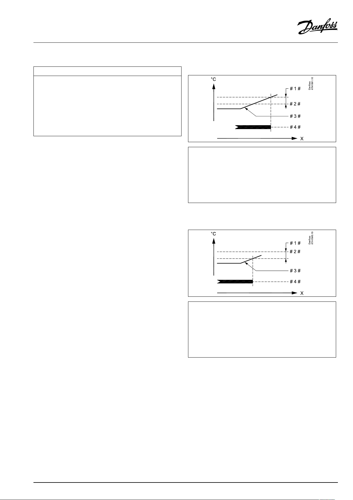
OperatingGuideECLComfort310,applicationA367
MENU>Settings>Tanktemperature
Stopdifference
OneDHWtanktemperaturesensor:
SetthenumberofdegreesaboveorbelowthedesiredDHWtemperature
thatwillstoptheDHWheating/charging.
TwoDHWtanktemperaturesensors:
SetthenumberofdegreesbelowthedesiredDHWtemperature,but
measuredbythelowertanktemperaturesensorthatwillstoptheDHW
heating/charging.
NOTE:Ifconditionforstop,relatedtothelowerDHWtanktemperature
sensor,ispresent,thestopisdonewhentheupperDHWtanktemperature
sensorhasatemperature2Khigherthanthestartdifferencelevel.
SeeAppendix“ParameterIDoverview”
Value:
Setthenumberofdegrees.
OneDHWtanktemperaturesensor(examplewithpositive‘Stop
difference’value):
1x194
=
X
#1#
#2#
#3#
#4#
Time
=
Stopdifference(ID1x194)
=
DesiredDHWtemperature
=
ActualDHWtemperature
=
DHWheating/chargingactivity
OneDHWtanktemperaturesensor(examplewithnegative‘Stop
difference’value):
=
X
#1#
#2#
#3#
#4#
Time
=
Stopdifference(ID1x194)
=
DesiredDHWtemperature
=
ActualDHWtemperature
=
DHWheating/chargingactivity
AQ005186455839en-010401
©Danfoss|2021.03|95
Page 96

OperatingGuideECLComfort310,applicationA367
TwoDHWtanktemperaturesensors,upperandlower.Upper
tanktemperatureisOKbeforelowertanktemperature:
=
X
#1#
#2#
#3#
#4#
#5#
#6#
Time
=
Startdifference(ID1x195)
=
DesiredDHWtemperature
=
Stopdifference(ID1x194)
=
UpperDHWtanktemperaturesensor
=
LowerDHWtanktemperaturesensor
=
DHWheating/chargingactivity
TwoDHWtanktemperaturesensors,upperandlower.Lower
tanktemperatureisOKbeforeuppertanktemperature:
=
X
#1#
#2#
#3#
#4#
#5#
#6#
Time
=
Startdifference(ID1x195)
=
DesiredDHWtemperature
=
Stopdifference(ID1x194)
=
UpperDHWtanktemperaturesensor
=
LowerDHWtanktemperaturesensor
=
DHWheating/chargingactivity
96|©Danfoss|2021.03
AQ005186455839en-010401
Page 97

OperatingGuideECLComfort310,applicationA367
MENU>Settings>Tanktemperature
Startdifference
SetthenumberofdegreesbelowthedesiredDHWtemperaturethatwill
starttheDHWheating(charging).
SeeAppendix“ParameterIDoverview”
Value:
Setthenumberofdegrees.
1x195
=
X
#1#
#2#
#3#
#4#
#5#
Example:
DesiredDHWtemp.:
Startdifference:
Result:
TheDHWheatingstartswhenthetemperaturemeasuredbythetank
temperaturesensor(upper)islowerthan52°C.
Time
=
Chargingdifference(ID1x193)
=
DesiredDHWtemperature
=
Startdifference(ID1x195)
=
ActualDHWtemperature
=
DHWheating/chargingactivity
55°C
-3K
AQ005186455839en-010401
©Danfoss|2021.03|97
Page 98

OperatingGuideECLComfort310,applicationA367
5.11Alarm
Thesection"Alarm"describesspecificapplicationrelatedissues.
ApplicationA367offersdifferenttypesofalarms:
Type:
1
2
Thealarmfunctionsactivatethealarmbellsymbol.
ThealarmfunctionsactivateA1,whichisrelay6intheECLComfort
310controller:
Thealarmrelaycanactivatealamp,ahorn,aninputtoanalarm
transmittingdeviceetc.
Thealarmsymbol/relayisactivated:
•(type1)aslongasthealarmreasonispresent(automaticreset).
•(type2)evenifthealarmreasondisappearsagain(manual
reset).
Alarmtype1:
Iftheflowtemperaturedeviatesmorethanthesetdifferencesfrom
thedesiredflowtemperature,thealarmsymbol/relaywillbe
activatedafterasetdelay.
Iftheflowtemperaturebecomesacceptable,thealarmsymbol/
relaywillbede-activated.
Alarmtype2:
Selectedtemperaturesensorscanbemonitored.
Shouldtheconnectiontothetemperaturesensorbedisconnected,
short-circuitedorthesensorgetsdefective,thealarmsymbol
/relaywillbeactivated.Inthe"Rawinputoverview"(MENU>
Commoncontrollersettings>System>Rawinputoverview)the
sensorinquestionismarkedandthealarmcanbereset.
Description:
Actualflowtemperaturediffers
fromthedesiredflowtemperature.
Disconnectionorshort-circuiting
ofatemperaturesensororits
connection.
ParametersindicatedwithanIDno.like"1x607"meanauniversal
parameter.
xstandsforcircuit/parametergroup.
98|©Danfoss|2021.03
AQ005186455839en-010401
Page 99

OperatingGuideECLComfort310,applicationA367
MENU>Settings>Alarm
Upperdifference
Thealarmisactivatediftheactualflowtemperatureincreasesmorethan
thesetdifference(acceptabletemperaturedifferenceabovethedesired
flowtemperature).Seealso'Delay' .
SeeAppendix“ParameterIDoverview”
1x147
Upperdifference
OFF:
Value:
Therelatedalarmfunctionisnotactive.
Thealarmfunctionisactiveiftheactualtemperature
getsabovetheacceptabledifference.
MENU>Settings>Alarm
Lowerdifference
Thealarmisactivatediftheactualflowtemperaturedecreasesmorethan
thesetdifference(acceptabletemperaturedifferencebelowthedesired
flowtemperature).Seealso'Delay' .
SeeAppendix“ParameterIDoverview”
OFF:
Value:
Therelatedalarmfunctionisnotactive.
Thealarmfunctionisactiveiftheactualtemperature
getsbelowtheacceptabledifference.
=
X
Y
#1#
#2#
1x148
Time
=
Temperature
=
Upperdifference
=
Desiredflowtemperature
Lowerdifference
=
X
Y
#1#
#2#
Time
=
Temperature
=
Lowerdifference
=
Desiredflowtemperature
AQ005186455839en-010401
©Danfoss|2021.03|99
Page 100

OperatingGuideECLComfort310,applicationA367
MENU>Settings>Alarm
Delay,example
Ifanalarmconditionfromeither'Upperdifference'or'Lowerdifference'is
presentforalongertimethanthesetdelay(inminutes),thealarmfunction
isactivated.
SeeAppendix“ParameterIDoverview”
1x149
Delay,example
Value:
Thealarmfunctionwillbeactivatedifthealarm
conditionremainsafterthesetdelay.
MENU>Settings>Alarm
Lowesttemp.
Thealarmfunctionwillnotbeactivatedifthedesiredflowtemperature
islowerthanthesetvalue.
SeeAppendix“ParameterIDoverview”
=
X
Y
#1#
#2#
#3#
#4#
1x150
Ifthecauseofthealarmdisappears,thealarmindicationandoutput
alsodisappear.
Time
=
Temperature
=
Lowerdifference
=
Desiredflowtemperature
=
Actualflowtemperature
=
Delay(ID1x149)
100|©Danfoss|2021.03
AQ005186455839en-010401
 Loading...