

Page 1
OperatingGuide
ECLComfort310,applicationA361
1.0TableofContents
1.0TableofContents...............................................1
1.1Importantsafetyandproductinformation.....................2
2.0Installation........................................................5
2.1Beforeyoustart.....................................................5
2.2Identifyingthesystemtype.......................................9
2.3Mounting...........................................................10
2.4Placingthetemperaturesensors................................14
2.5Electricalconnections.............................................16
2.6InsertingtheECLApplicationKey..............................25
2.7Checklist............................................................32
2.8Navigation,ECLApplicationKeyA361.........................33
3.0Dailyuse.........................................................36
3.1Howtonavigate...................................................36
3.2Understandingthecontrollerdisplay..........................37
3.3Ageneraloverview:Whatdothesymbolsmean?...........40
3.4Monitoringtemperaturesandsystem
components........................................................41
3.5Influenceoverview................................................42
3.6Manualcontrol.....................................................43
3.7Schedule............................................................44
4.0Settingsoverview............................................45
5.0Settings...........................................................47
5.1IntroductiontoSettings..........................................47
5.2Flowtemperature..................................................48
5.3Returnlimit.........................................................53
5.4Flow/powerlimit.................................................57
5.5Optimization........................................................61
5.6Controlparameters................................................67
5.7Pumpcontrol.......................................................71
5.8Refillwater..........................................................74
5.9Application.........................................................79
5.10Alarm................................................................84
5.11Alarmoverview....................................................88
6.0Commoncontrollersettings..............................89
6.1Introductionto‘Commoncontrollersettings’................89
6.2Time&Date.........................................................90
6.3Holiday..............................................................91
6.4Inputoverview.....................................................93
6.5Log...................................................................94
6.6Outputoverride....................................................95
6.7Keyfunctions.......................................................96
6.8System...............................................................98
7.0Miscellaneous................................................105
7.1ECA30/31setupprocedures.................................105
7.2Overridefunction................................................113
7.3Severalcontrollersinthesamesystem......................116
7.4Frequentlyaskedquestions....................................119
7.5Definitions........................................................122
7.6Type(ID6001),overview.......................................126
7.7Automatic/manualupdateoffirmware.....................127
7.8ParameterIDoverview..........................................128
©Danfoss|2021.02AQ000086455681en-010402|1
Page 2
OperatingGuideECLComfort310,applicationA361
1.1Importantsafetyandproductinformation
1.1.1Importantsafetyandproductinformation
ThisInstallationGuideisassociatedwithECLApplicationKeyA361
(ordercodeno.087H3804).
ThefunctionscanberealizedwithECLComfort310.
TheapplicationA361complieswithECLComfortcontroller310as
ofsoftwareversion1.10(visibleatstart-upofthecontrollerandin
‘Commoncontrollersettings’in‘System’).
AdditionaldocumentationforECLComfort210and310,modules
andaccessoriesisavailableonhttp://heating.danfoss.com/.
Applicationkeysmightbereleasedbeforealldisplaytextsare
translated.InthiscasethetextisinEnglish.
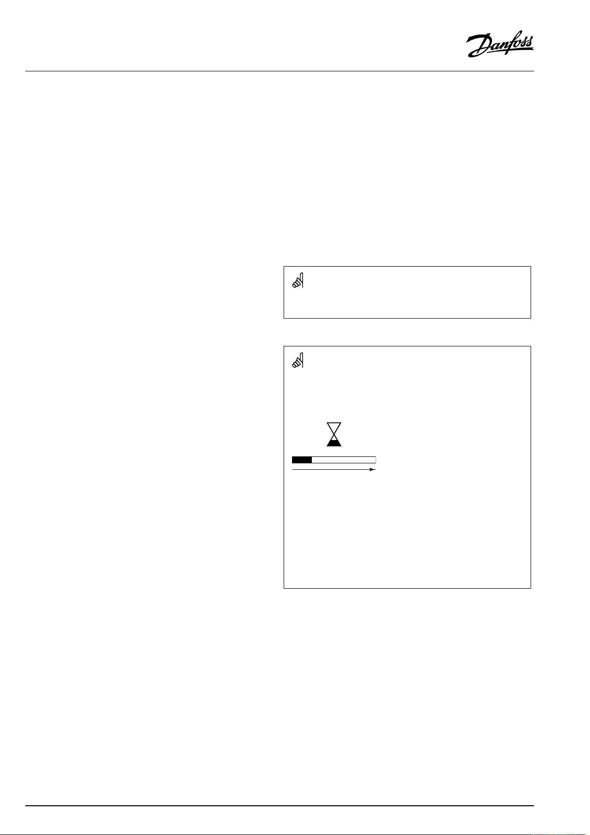
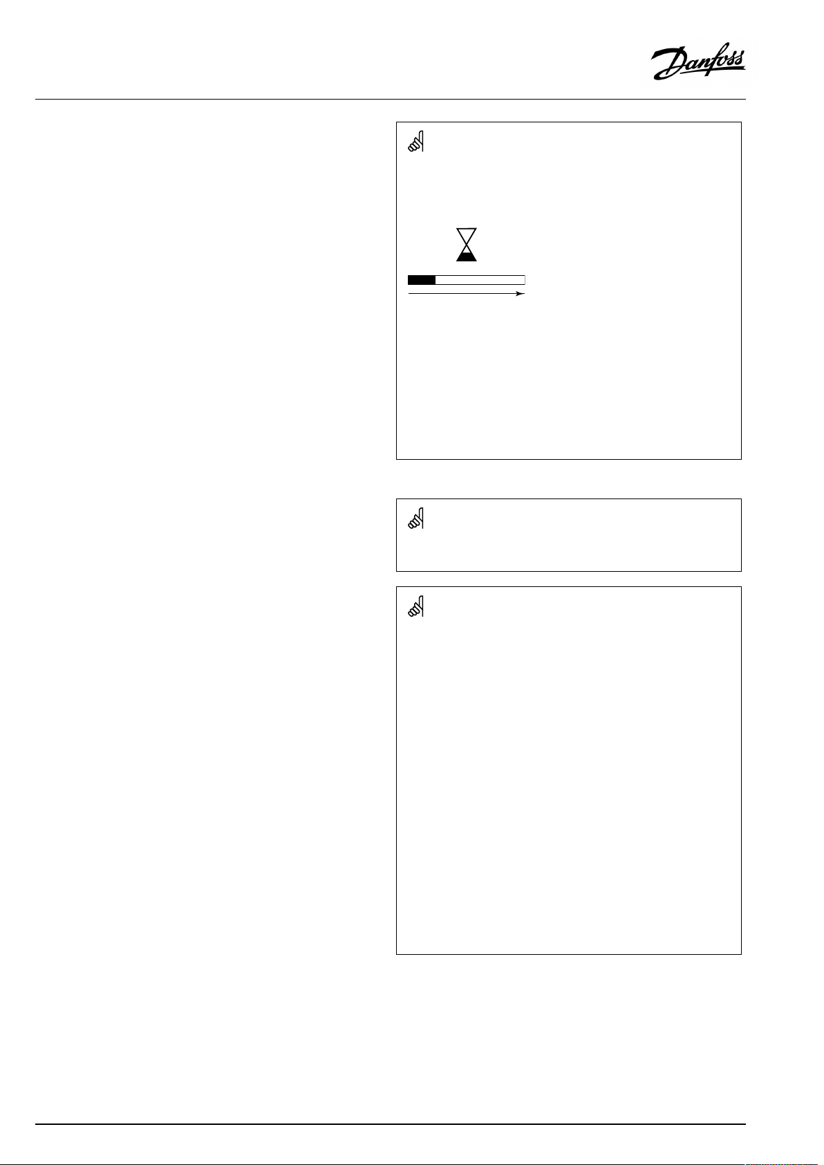
Automaticupdateofcontrollersoftware(firmware):
Thesoftwareofthecontrollerisupdatedautomaticallywhenthekey
isinserted(asofcontrollerversion1.11(ECL210/310)andversion
1.58(ECL296)).Thefollowinganimationwillbeshownwhenthe
softwareisbeingupdated:
Progressbar
Duringupdate:
•DonotremovetheKEY
Ifthekeyisremovedbeforethehour-glassisshown,youhave
tostartafresh.
•Donotdisconnectthepower
Ifthepowerisinterruptedwhenthehour-glassisshown,the
controllerwillnotwork.
•Manualupdateofcontrollersoftware(firmware):
Seethesection"Automatic/manualupdateoffirmware"
2|©Danfoss|2021.02
AQ000086455681en-010402
Page 3
OperatingGuideECLComfort310,applicationA361
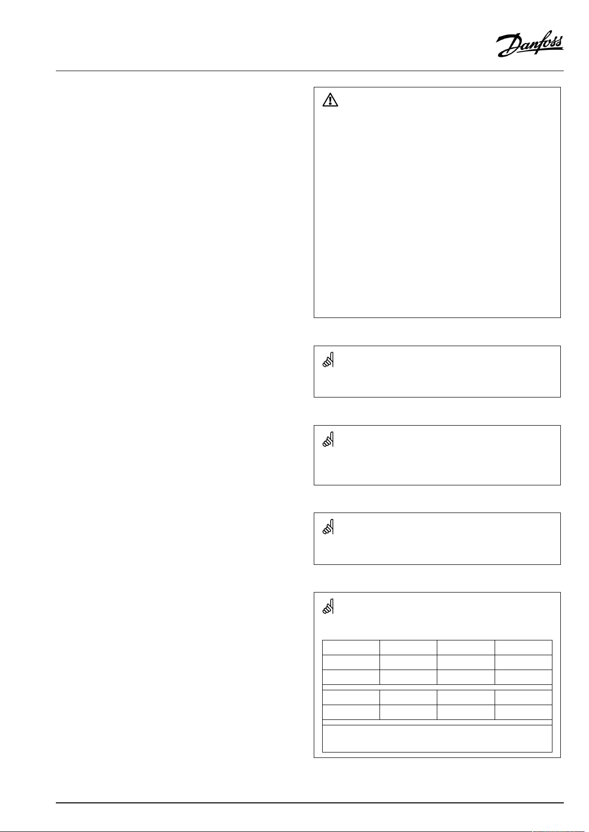
SafetyNote
Toavoidinjuryofpersonsanddamagestothedevice,itisabsolutely
necessarytoreadandobservetheseinstructionscarefully.
Necessaryassembly,start-up,andmaintenanceworkmustbe
performedbyqualifiedandauthorizedpersonnelonly.
Locallegislationsmustberespected.Thiscomprisesalsocable
dimensionsandtypeofisolation(doubleisolatedat230V).
AfusefortheECLComfortinstallationismax.10Atypically.
TheambienttemperaturerangesforECLComfortinoperationare:
ECLComfort210/310:0-55°C
ECLComfort296:0-45°C.
Exceedingthetemperaturerangecanresultinmalfunctions.
Installationmustbeavoidedifthereisariskforcondensation(dew).
Thewarningsignisusedtoemphasizespecialconditionsthatshould
betakenintoconsideration.
Thissymbolindicatesthatthisparticularpieceofinformationshould
bereadwithspecialattention.
AsthisOperatingGuidecoversseveralsystemtypes,specialsystem
settingswillbemarkedwithasystemtype.Allsystemtypesareshown
inthechapter:'Identifyingyoursystemtype'.
°C(degreesCelsius)isameasuredtemperaturevaluewhereasK
(Kelvin)oftenisusedfortemperaturedifferences.
TheIDno.isuniquefortheselectedparameter.
ExampleFirstdigitSeconddigitLastthreedigits
1117411174
-
Circuit1Parameterno.
12174
IfanIDdescriptionismentionedmorethanonce,itmeansthatthere
arespecialsettingsforoneormoresystemtypes.Itwillbemarked
withthesystemtypeinquestion(e.g.12174-A266.9).
1
-
2
Circuit2Parameterno.
AQ000086455681en-010402
174
©Danfoss|2021.02|3
Page 4
OperatingGuideECLComfort310,applicationA361
ParametersindicatedwithanIDno.like"1x607"meanauniversal
parameter.
xstandsforcircuit/parametergroup.
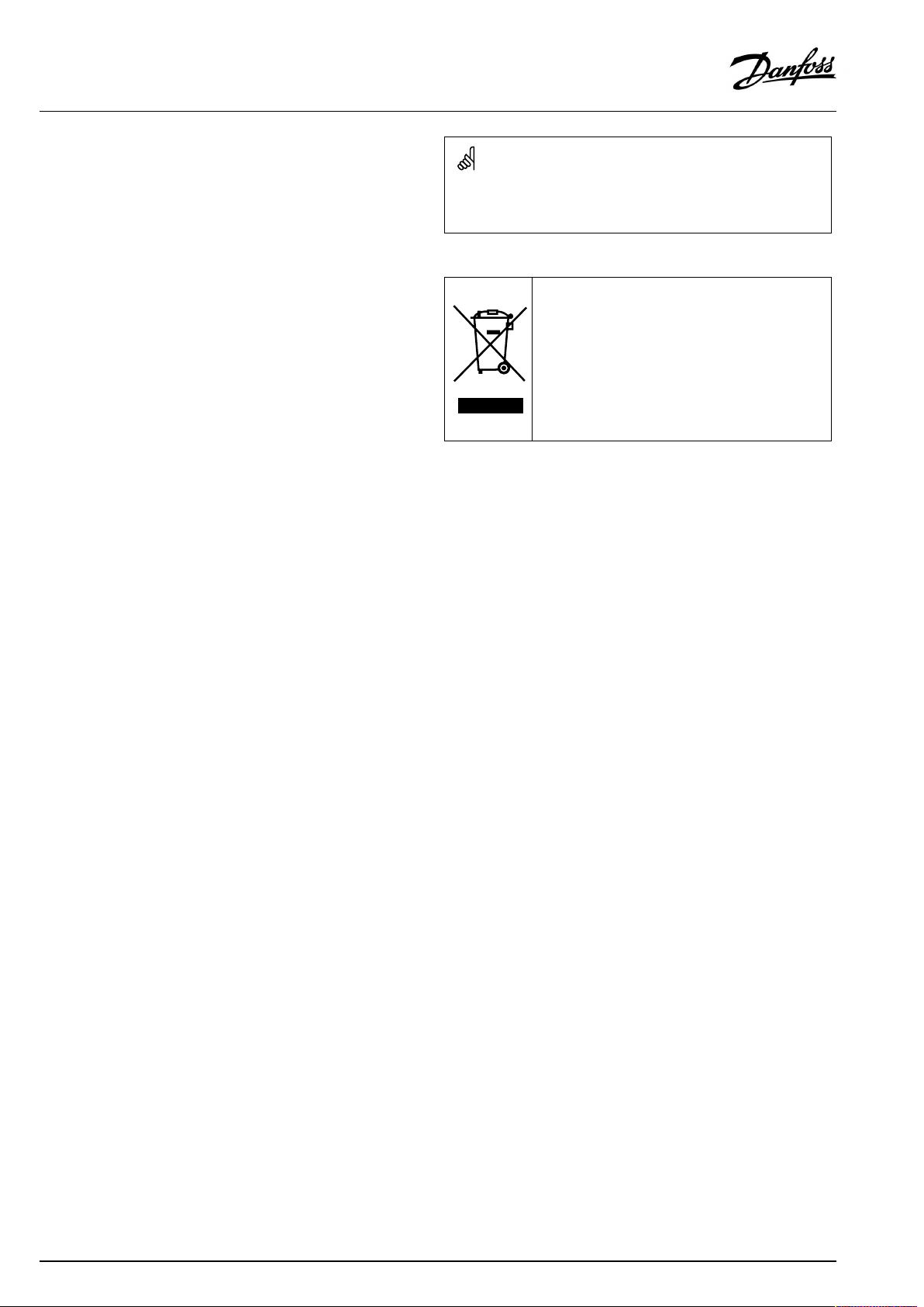
DisposalNote
Thissymbolontheproductindicatesthatitmaynot
bedisposedofashouseholdwaste.
Itmustbehandedovertotheapplicabletake-back
schemefortherecyclingofelectricalandelectronic
equipment.
•Disposeoftheproductthroughchannelsprovided
forthispurpose.
•Complywithalllocalandcurrentlyapplicablelaws
andregulations.
4|©Danfoss|2021.02
AQ000086455681en-010402
Page 5
OperatingGuideECLComfort310,applicationA361
2.0Installation
2.1Beforeyoustart
TheapplicationA361.1isveryflexible.Thesearethebasic
principles:
Heating(circuit1and2):
Typically,theflowtemperatureisadjustedaccordingtoyour
requirements.TheflowtemperaturesensorS3(circuit1)and
S4(circuit2)arethemostimportantsensors.Thedesiredflow
temperaturesatS3andS4arecalculatedintheECLcontroller,
basedontheoutdoortemperature(S1).Thelowertheoutdoor
temperature,thehigherthedesiredflowtemperature.
Bymeansofaweekschedule,theheatingcircuitcanbein
‘Comfort’or‘Saving’mode(twodifferenttemperaturevaluesfor
desiredroomtemperature).
ThemotorizedcontrolvalvesM1(circuit1)andM2(circuit2)are
openedgraduallywhentheflowtemperatureislowerthanthe
desiredflowtemperatureandviceversa.
ThereturntemperaturesS5(circuit1)andS6(circuit2)tothe
districtheatingsupplyshouldnotbetoohigh.Ifso,thedesired
flowtemperaturecanbeadjusted(typicallytoalowervalue),thus
resultinginagradualclosingofthemotorizedcontrolvalves.
Inboiler-basedheatingsupplythereturntemperatureshouldnot
betoolow(sameadjustmentprocedureasabove).
Furthermore,thereturntemperaturelimitationcanbedependent
oftheoutdoortemperature.Typically,thelowertheoutdoor
temperature,thehighertheacceptedreturntemperature.
ThecirculationpumpinquestionisONatheatdemandoratfrost
protection.
TheheatingcanbeswitchedOFFwhentheoutdoortemperatureis
higherthanaselectablevalue.
Thestaticpressureonthesecondaryside(consumerside)can1)
bemeasuredasa0-10Vsignal(fromapressuretransmitter)or
2)beaswitchsignalfromapressureswitch.Incaseofatoolow
pressure,therefillwaterfunctionwillsupplementwithwaterfrom
thesupplyside.
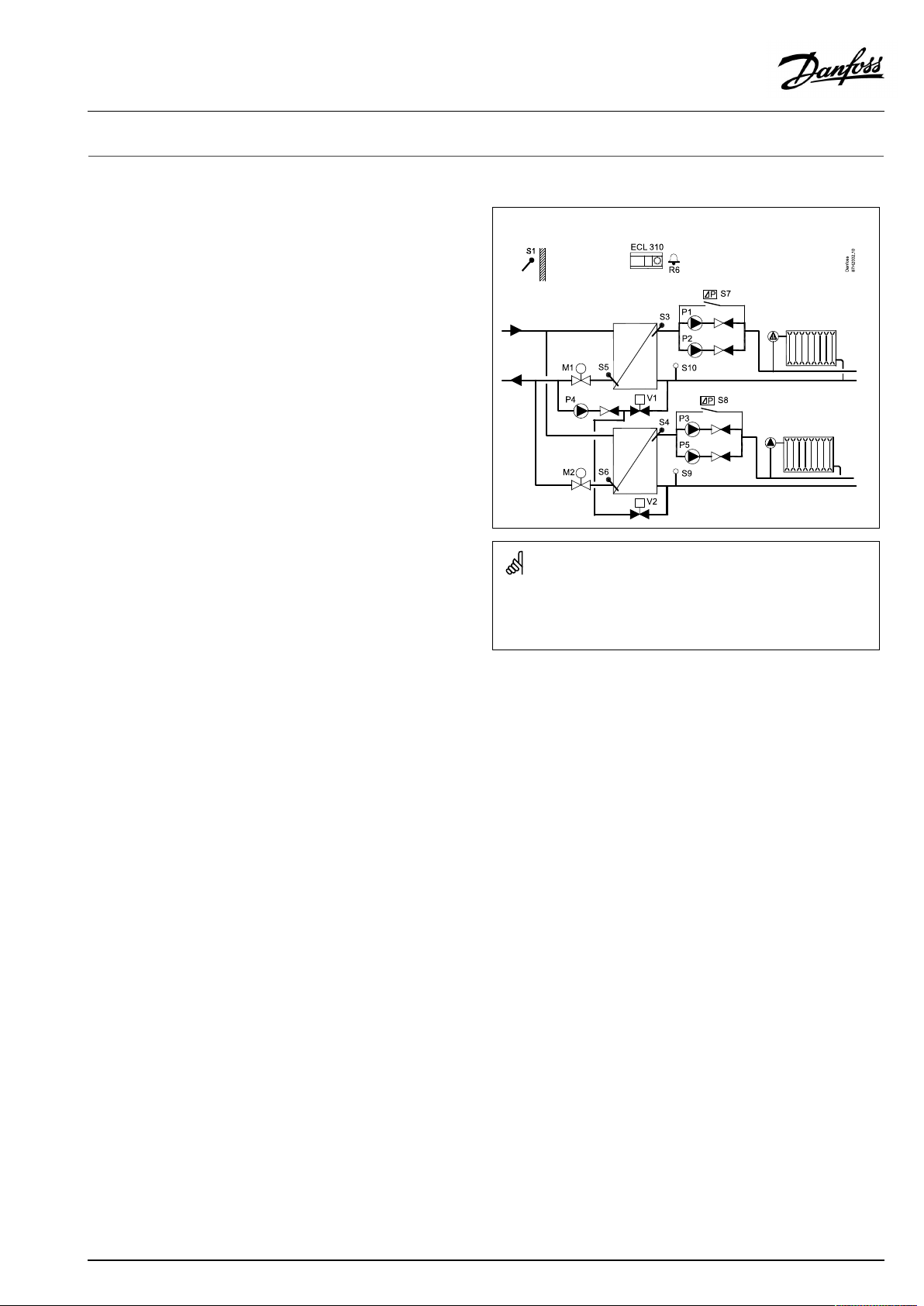
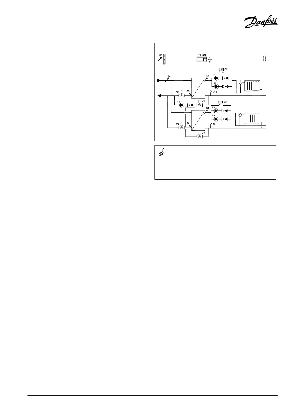
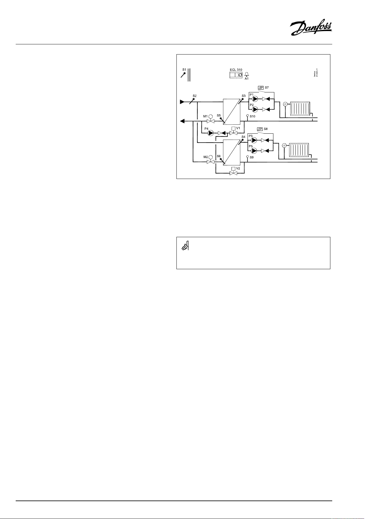
TypicalA361.1application:
Theshowndiagramisafundamentalandsimplifiedexampleanddoes
notcontainallcomponentsthatarenecessaryinasystem.
AllnamedcomponentsareconnectedtotheECLComfortcontroller.
Listofcomponents:
S1
Outdoortemperaturesensor
S3
Flowtemperaturesensor,circuit1
S4
Flowtemperaturesensor,circuit2
S5Returntemperaturesensor,circuit1
S6Returntemperaturesensor,circuit2
S7
Differentialpressureswitch,circuit1
S8
Differentialpressureswitch,circuit2
S9
Pressuretransmitterorpressureswitch,circuit2
S10
Pressuretransmitterorpressureswitch,circuit1
P1
Circulationpump,circuit1
P2
Circulationpump,circuit1
P3
Circulationpump,circuit2
P4
Refillwaterpump
P5
Circulationpump,circuit2
M1
Motorizedcontrolvalve,circuit1
M2
Motorizedcontrolvalve,circuit2
V1
Solenoidvalve,circuit1,refillwatervalve
V2
Solenoidvalve,circuit2,refillwatervalve
R6
Relayoutput,alarm
AQ000086455681en-010402
©Danfoss|2021.02|5
Page 6
OperatingGuideECLComfort310,applicationA361
ApplicationA361.1ingeneral:
ThecirculationpumpsP1andP2(circuit1)/P3andP5(circuit2)
workinshiftaccordingtoaschedule.Onepumpisusedasspare
pumpandtheotherpumpisworking.Incaseofmalfunction
(missingdifferentialpressure)ofonepump,theotherpumpwill
takeover.Analarmwillbegeneratedandthedefectivepumpcan
beinspected/repaired.
Alarm(relay6)canbeactivatedif:
•Theactualflowtemperaturediffersfromthedesiredflow
temperature.
•Theactivatedcirculationpumpdoesnotgenerateapressure
difference.
•Therefillwaterfunctiondoesnotgenerateapressurewithin
apresettime.
ModbuscommunicationtoaSCADAsystemcanbeestablished.
M-buscommunicationenablesconnectiontofloworenergymeter.
Thecontrollercanlimitthefloworenergytoasetmaximumbut
alsoinrelationtotheoutdoortemperature.
Furthermore,theM-busdatacanbetransferredtotheModbus
communication.
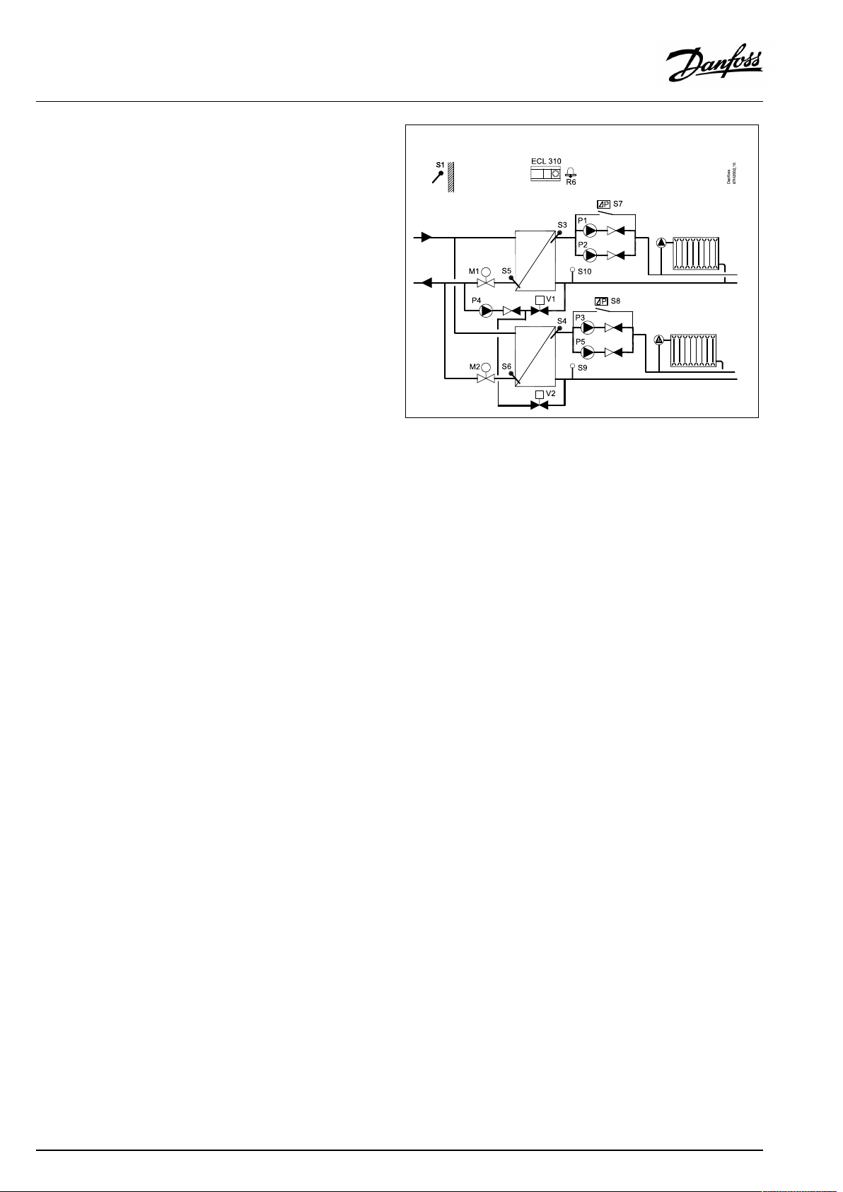
TypicalA361.1application:
6|©Danfoss|2021.02
AQ000086455681en-010402
Page 7
OperatingGuideECLComfort310,applicationA361
TheapplicationA361.2isveryflexible.Thesearethebasic
principles:
Heating(circuit1and2):
Typically,theflowtemperatureisadjustedaccordingtoyour
requirements.TheflowtemperaturesensorS3(circuit1)and
S4(circuit2)arethemostimportantsensors.Thedesiredflow
temperaturesatS3andS4arecalculatedintheECLcontroller,
basedontheoutdoortemperature(S1).Thelowertheoutdoor
temperature,thehigherthedesiredflowtemperature.
Thesupplytemperature(S2)isusedto1)controltheS3andS4
temperaturesinrelationtotheS2temperatureor2)maximizethe
limitofthedesiredflowtemperature.
Thefactorysetting,wherethesupplytemperature(S2)determines
thedesiredflowtemperature,doesnotchangethedesiredflow
temperatureaccordingto‘Comfort’or‘Saving’mode.
However,ifthesupplytemperature(S2)determinesamax.
limitationofthedesiredflowtemperature,the‘Comfort’and
‘Saving’modewillhavetwodifferenttemperaturevaluesfor
desiredroomtemperature.
ThemotorizedcontrolvalvesM1(circuit1)andM2(circuit2)are
openedgraduallywhentheflowtemperatureislowerthanthe
desiredflowtemperatureandviceversa.
ThereturntemperaturesS5(circuit1)andS6(circuit2)tothe
districtheatingsupplyshouldnotbetoohigh.Ifso,thedesired
flowtemperaturecanbeadjusted(typicallytoalowervalue),thus
resultinginagradualclosingofthemotorizedcontrolvalves.
Inboiler-basedheatingsupplythereturntemperatureshouldnot
betoolow(sameadjustmentprocedureasabove).
Furthermore,thereturntemperaturelimitationcanbedependent
oftheoutdoortemperature.Typically,thelowertheoutdoor
temperature,thehighertheacceptedreturntemperature.
ThecirculationpumpinquestionisONatheatdemandoratfrost
protection.
TheheatingcanbeswitchedOFFwhentheoutdoortemperatureis
higherthanaselectablevalue.
Thestaticpressureonthesecondaryside(consumerside)can1)
bemeasuredasa0-10Vsignal(fromapressuretransmitter)or
2)beaswitchsignalfromapressureswitch.Incaseofatoolow
pressure,therefillwaterfunctionwillsupplementwithwaterfrom
thesupplyside.
TypicalA361.2application:
Theshowndiagramisafundamentalandsimplifiedexampleanddoes
notcontainallcomponentsthatarenecessaryinasystem.
AllnamedcomponentsareconnectedtotheECLComfortcontroller.
Listofcomponents:
S1
Outdoortemperaturesensor
S2
Supplyflowtemperaturesensor
S3
Flowtemperaturesensor,circuit1
S4
Flowtemperaturesensor,circuit2
S5Returntemperaturesensor,circuit1
S6Returntemperaturesensor,circuit2
S7
Differentialpressureswitch,circuit1
S8
Differentialpressureswitch,circuit2
S9
Pressuretransmitterorpressureswitch,circuit2
S10
Pressuretransmitterorpressureswitch,circuit1
P1
Circulationpump,circuit1
P2
Circulationpump,circuit1
P3
Circulationpump,circuit2
P4
Refillwaterpump
P5
Circulationpump,circuit2
M1
Motorizedcontrolvalve,circuit1
M2
Motorizedcontrolvalve,circuit2
V1
Solenoidvalve,circuit1,refillwatervalve
V2
Solenoidvalve,circuit2,refillwatervalve
R6
Relayoutput,alarm
AQ000086455681en-010402
©Danfoss|2021.02|7
Page 8
OperatingGuideECLComfort310,applicationA361
ApplicationA361.2ingeneral:
ThecirculationpumpsP1andP2(circuit1)/P3andP5(circuit2)
workinshiftaccordingtoaschedule.Onepumpisusedasspare
pumpandtheotherpumpisworking.Incaseofmalfunction
(missingdifferentialpressure)ofonepump,theotherpumpwill
takeover.Analarmwillbegeneratedandthedefectivepumpcan
beinspected/repaired.
Alarm(relay6)canbeactivatedif:
•Theactualflowtemperaturediffersfromthedesiredflow
temperature.
•Theactivatedcirculationpumpdoesnotgenerateapressure
difference.
•Therefillwaterfunctiondoesnotgenerateapressurewithin
apresettime.
ModbuscommunicationtoaSCADAsystemcanbeestablished.
M-buscommunicationenablesconnectiontofloworenergymeter.
Thecontrollercanlimitthefloworenergytoasetmaximumbut
alsoinrelationtotheoutdoortemperature.
Furthermore,theM-busdatacanbetransferredtotheModbus
communication.
TypicalA361.2application:
Thecontrollerispre-programmedwithfactorysettingsthatareshown
inthe‘ParameterIDoverview’appendix.
8|©Danfoss|2021.02
AQ000086455681en-010402
Page 9
OperatingGuideECLComfort310,applicationA361
2.2Identifyingthesystemtype
Sketchyourapplication
TheECLComfortcontrollerseriesisdesignedforawiderange
ofheating,domestichot-water(DHW)andcoolingsystemswith
differentconfigurationsandcapacities.Ifyoursystemdiffers
fromthediagramsshownhere,youmaywanttomakeasketch
ofthesystemabouttobeinstalled.Thismakesiteasiertouse
theOperatingGuide,whichwillguideyoustep-by-stepfrom
installationtofinaladjustmentsbeforetheend-usertakesover.
TheECLComfortcontrollerisauniversalcontrollerthatcanbe
usedforvarioussystems.Basedontheshownstandardsystems,
itispossibletoconfigureadditionalsystems.Inthischapteryou
findthemostfrequentlyusedsystems.Ifyoursystemisnotquite
asshownbelow,findthediagramwhichhasthebestresemblance
withyoursystemandmakeyourowncombinations.
SeetheInstallationGuide(deliveredwiththeapplicationkey)for
applicationtypes/sub-types.
Thecirculationpump(s)inheatingcircuit(s)canbeplacedintheflow
aswellasthereturn.Placethepumpaccordingtothemanufacturer’s
specification.
AQ000086455681en-010402
©Danfoss|2021.02|9
Page 10
OperatingGuideECLComfort310,applicationA361
2.3Mounting
2.3.1MountingtheECLComfortcontroller
SeetheInstallationGuidewhichisdeliveredtogetherwiththe
ECLComfortcontroller.
Foreasyaccess,youshouldmounttheECLComfortcontrollernear
thesystem.
ECLComfort210/296/310canbemounted
•onawall
•onaDINrail(35mm)
ECLComfort296canbemounted
•inapanelcut-out
ECLComfort210canbemountedinanECLComfort310basepart
(forfutureupgrade).
Screws,PGcableglandsandrawlplugsarenotsupplied.
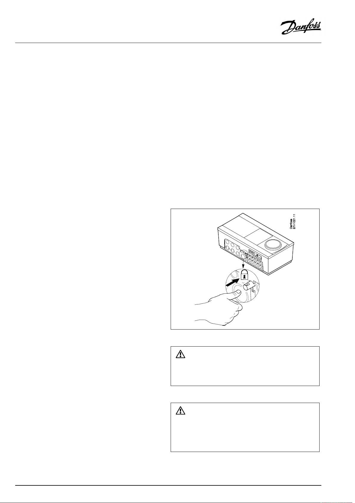
LockingtheECLComfort210/310controller
InordertofastentheECLComfortcontrollertoitsbasepart,secure
thecontrollerwiththelockingpin.
10|©Danfoss|2021.02
Topreventinjuriestopersonsorthecontroller,thecontrollerhasto
besecurelylockedintothebase.Forthispurpose,pressthelocking
pinintothebaseuntilaclickisheardandthecontrollernolonger
canberemovedfromthebase.
Ifthecontrollerisnotsecurelylockedintothebasepart,thereisarisk
thatthecontrollerduringoperationcanunlockfromthebaseandthe
basewithterminals(andalsothe230Va.c.connections)areexposed.
Topreventinjuriestopersons,alwaysmakesurethatthecontroller
issecurelylockedintoitsbase.Ifthisisnotthecase,thecontroller
shouldnotbeoperated!
AQ000086455681en-010402
Page 11
OperatingGuideECLComfort310,applicationA361
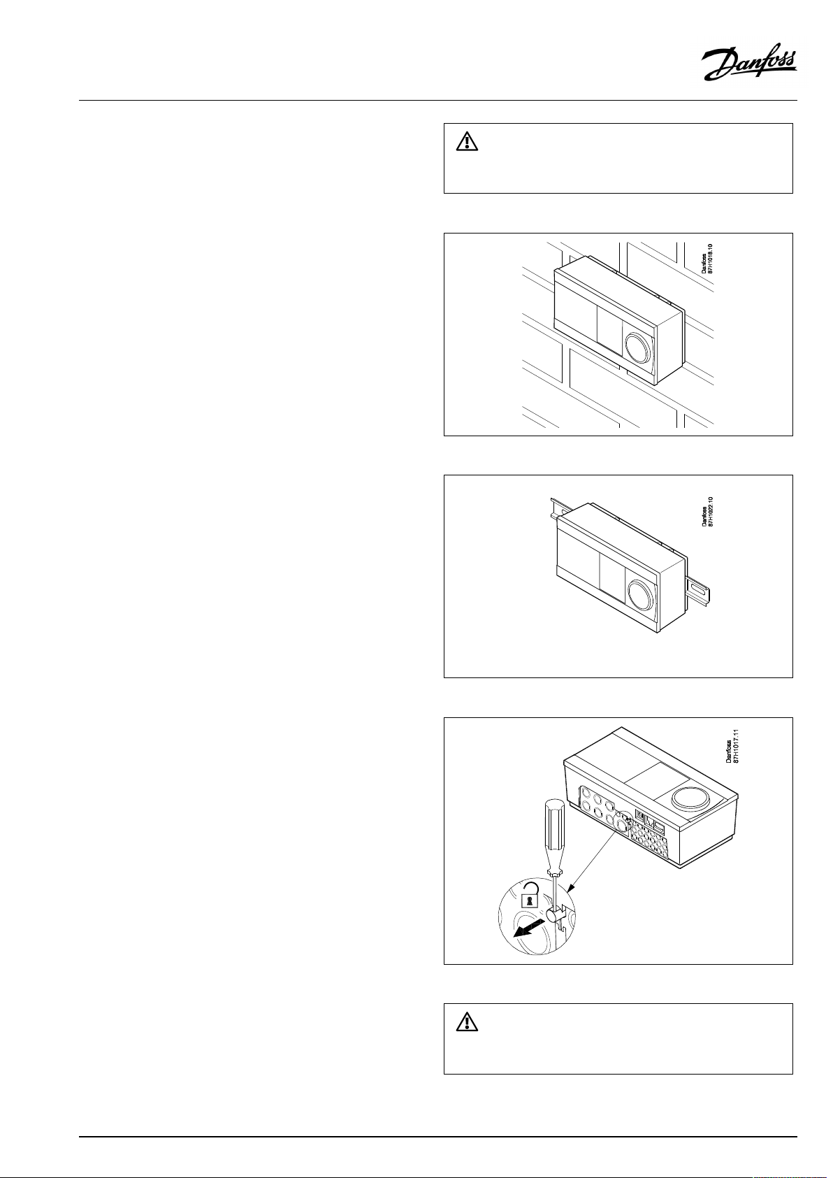
Mountingonawall
Mountthebasepartonawallwithasmoothsurface.Establishthe
electricalconnectionsandpositionthecontrollerinthebasepart.
Securethecontrollerwiththelockingpin.
MountingonaDINrail(35mm)
MountthebasepartonaDINrail.Establishtheelectrical
connectionsandpositionthecontrollerinthebasepart.Secure
thecontrollerwiththelockingpin.
Theeasywaytolockthecontrollertoitsbaseorunlockitistousea
screwdriveraslever.
DismountingtheECLComfortcontroller
Inordertoremovethecontrollerfromthebasepart,pulloutthe
lockingpinbymeansofascrewdriver.Thecontrollercannowbe
removedfromthebasepart.
Theeasywaytolockthecontrollertoitsbaseorunlockitistousea
screwdriveraslever.
AQ000086455681en-010402
©Danfoss|2021.02|11
Page 12
OperatingGuideECLComfort310,applicationA361
2.3.2MountingtheRemoteControlUnitsECA30/31
Selectoneofthefollowingmethods:
•Mountingonawall,ECA30/31
•Mountinginapanel,ECA30
Screwsandrawlplugsarenotsupplied.
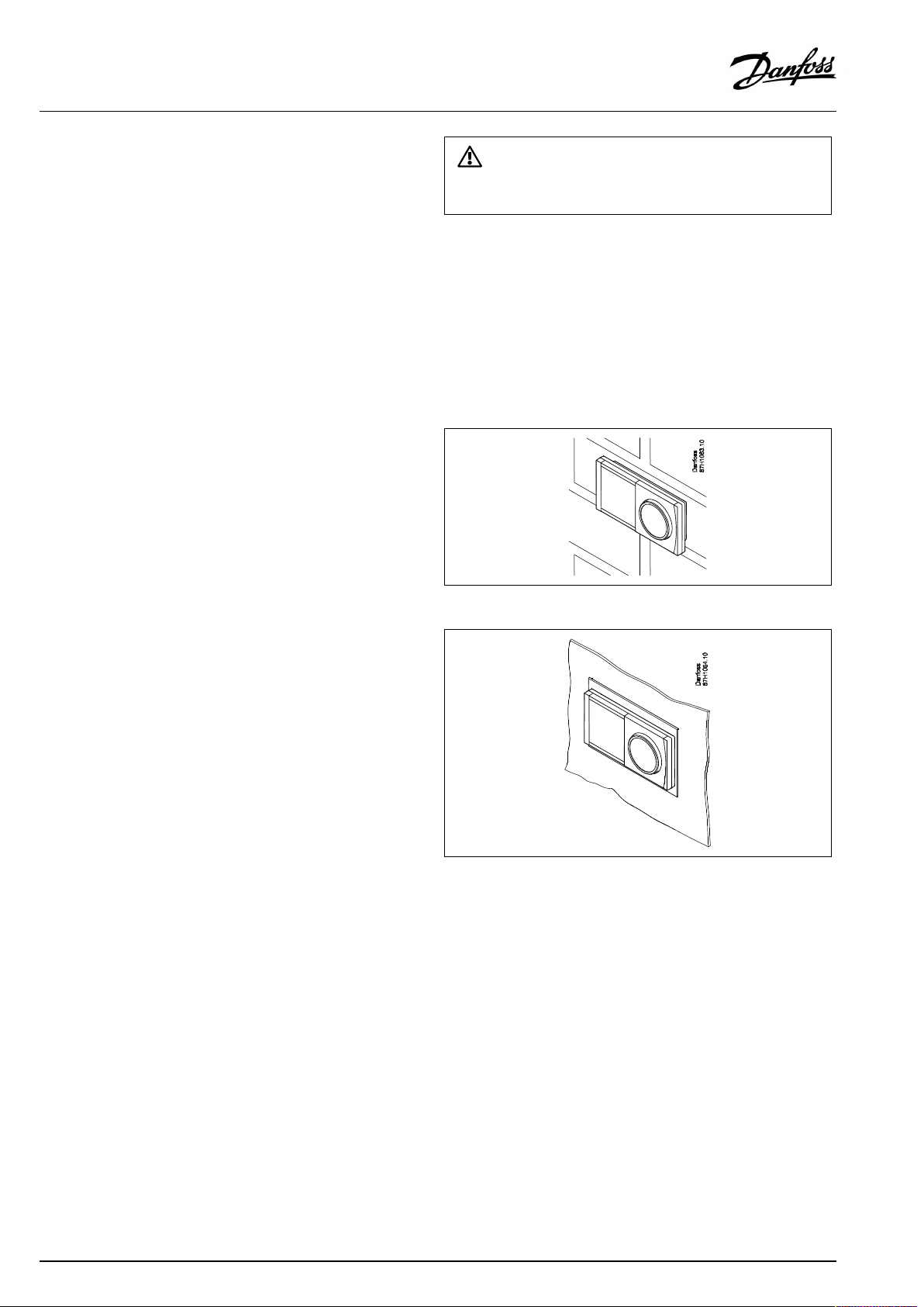
Mountingonawall
MountthebasepartoftheECA30/31onawallwithasmooth
surface.Establishtheelectricalconnections.PlacetheECA30/
31inthebasepart.
BeforeremovingtheECLComfortcontrollerfromthebasepart,ensure
thatthesupplyvoltageisdisconnected.
Mountinginapanel
MounttheECA30inapanelusingtheECA30framekit(ordercode
no.087H3236).Establishtheelectricalconnections.Securethe
framewiththeclamp.PlacetheECA30inthebasepart.TheECA
30canbeconnectedtoanexternalroomtemperaturesensor.
TheECA31mustnotbemountedinapanelifthehumidity
functionistobeused.
12|©Danfoss|2021.02
AQ000086455681en-010402
Page 13
OperatingGuideECLComfort310,applicationA361
2.3.3MountingtheinternalI/OmoduleECA32
MountingoftheinternalI/OmoduleECA32
TheECA32module(ordercodeno.087H3202)mustbeinserted
intotheECLComfort310/310Bbasepartforadditionalinputand
outputsignalsinrelevantapplications.
TheconnectionbetweentheECLComfort310/310BandECA32
isa10-pole(2x5)connector.Theconnectionisautomatically
establishedwhentheECLComfort310/310Bisplacedonthe
basepart.
AQ000086455681en-010402
©Danfoss|2021.02|13
Page 14
OperatingGuideECLComfort310,applicationA361
2.4Placingthetemperaturesensors
2.4.1Placingthetemperaturesensors
Itisimportantthatthesensorsaremountedinthecorrectposition
inyoursystem.
Thetemperaturesensormentionedbelowaresensorsusedforthe
ECLComfort210/296/310serieswhichnotallwillbeneeded
foryourapplication!
Outdoortemperaturesensor(ESMT)
Theoutdoorsensorshouldbemountedonthatsideofthebuilding
whereitislesslikelytobeexposedtodirectsunshine.Itshouldnot
beplacedclosetodoors,windowsorairoutlets.
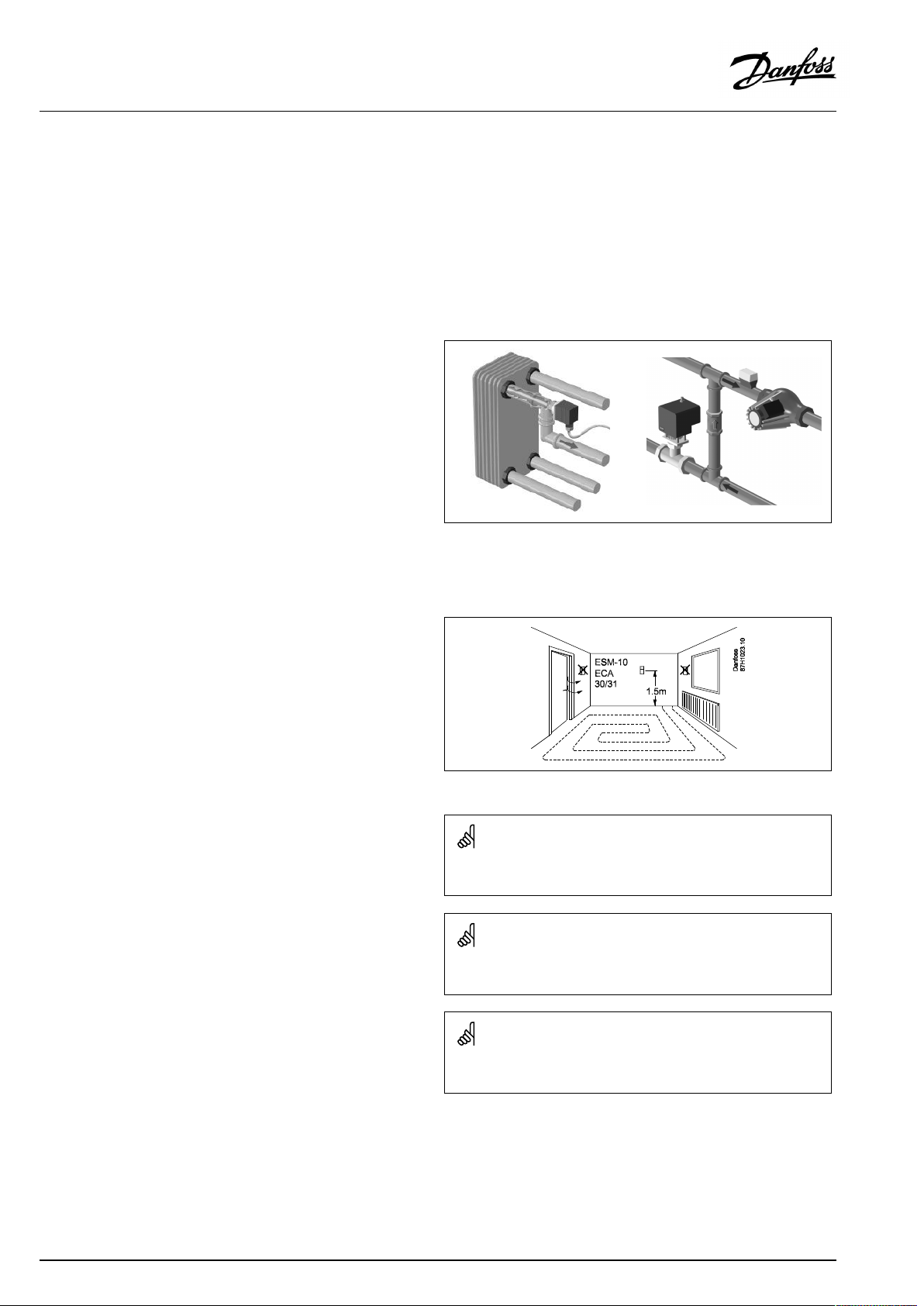
Flowtemperaturesensor(ESMU,ESM-11orESMC)
Placethesensormax.15cmfromthemixingpoint.Insystems
withheatexchanger,DanfossrecommendsthattheESMU-typeto
beinsertedintotheexchangerflowoutlet.
Makesurethatthesurfaceofthepipeiscleanandevenwhere
thesensorismounted.
Returntemperaturesensor(ESMU,ESM-11orESMC)
Thereturntemperaturesensorshouldalwaysbeplacedsothatit
measuresarepresentativereturntemperature.
Roomtemperaturesensor
(ESM-10,ECA30/31RemoteControlUnit)
Placetheroomsensorintheroomwherethetemperatureistobe
controlled.Donotplaceitonoutsidewallsorclosetoradiators,
windowsordoors.
Boilertemperaturesensor(ESMU,ESM-11orESMC)
Placethesensoraccordingtotheboilermanufacturer’s
specification.
Airducttemperaturesensor(ESMB-12orESMUtypes)
Placethesensorsothatitmeasuresarepresentativetemperature.
DHWtemperaturesensor(ESMUorESMB-12)
PlacetheDHWtemperaturesensoraccordingtothemanufacturer’s
specification.
Slabtemperaturesensor(ESMB-12)
Placethesensorinaprotectiontubeintheslab.
ESM-11:Donotmovethesensorafterithasbeenfastenedinorderto
avoiddamagetothesensorelement.
ESM-11,ESMCandESMB-12:Useheatconductingpasteforquick
measurementofthetemperature.
ESMUandESMB-12:Usingasensorpockettoprotectthesensorwill,
however,resultinaslowertemperaturemeasurement.
14|©Danfoss|2021.02
AQ000086455681en-010402
Page 15
OperatingGuideECLComfort310,applicationA361
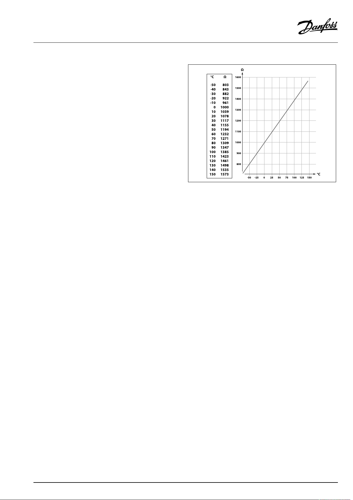
Pt1000temperaturesensor(IEC751B,1000Ω/0°C)
Relationshipbetweentemperatureandohmicvalue:
AQ000086455681en-010402
©Danfoss|2021.02|15
Page 16
OperatingGuideECLComfort310,applicationA361
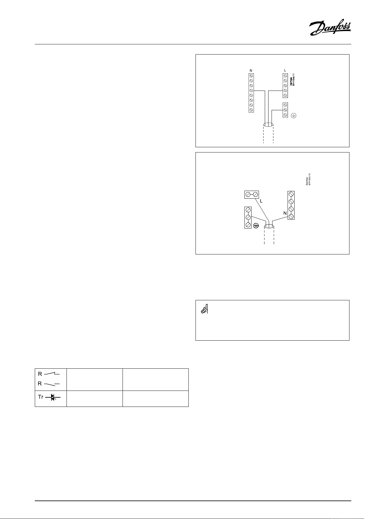
2.5Electricalconnections
2.5.1Electricalconnections230Va.c.
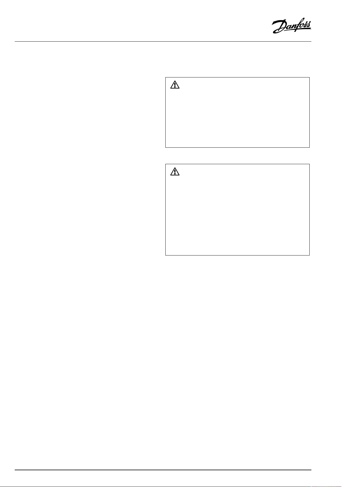
Warning
ElectricconductorsonPCB(PrintedCircuitBoard)forsupplyvoltage,
relaycontactsandtriacoutputsdonothavemutualsafetydistanceof
minimum6mm.Theoutputsarenotallowedtobeusedasgalvanic
separated(voltfree)outputs.
Ifagalvanicseparatedoutputisneeded,anauxiliaryrelayis
recommended.
24Voltcontrolledunits,forexampleactuators,aretobecontrolledby
meansofECLComfort310,24Voltversion.
SafetyNote
Necessaryassembly,start-up,andmaintenanceworkmustbe
performedbyqualifiedandauthorizedpersonnelonly.
Locallegislationsmustberespected.Thiscomprisesalsocablesize
andisolation(reinforcedtype).
AfusefortheECLComfortinstallationismax.10Atypically.
TheambienttemperaturerangefortheECLComfortinoperationis
0-55°C.Exceedingthistemperaturerangecanresultinmalfunctions.
Installationmustbeavoidedifthereisariskforcondensation(dew).
16|©Danfoss|2021.02
AQ000086455681en-010402
Page 17
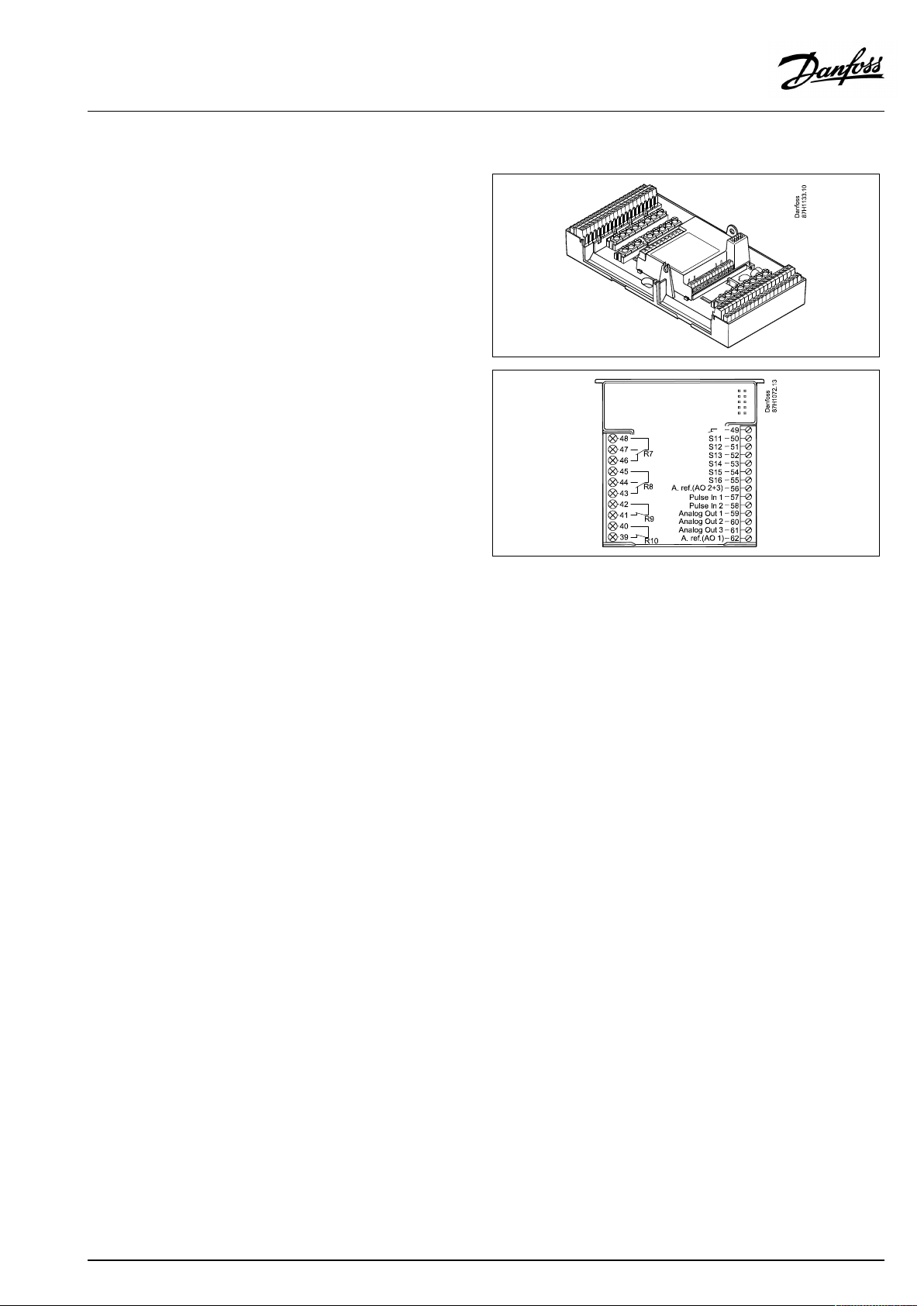
OperatingGuideECLComfort310,applicationA361
Thecommongroundterminalisusedforconnectionofrelevant
components(pumps,motorizedcontrolvalves).
ECL210/310
ECL296
SeealsotheInstallationGuide(deliveredwiththeapplicationkey)
forapplicationspecificconnections.
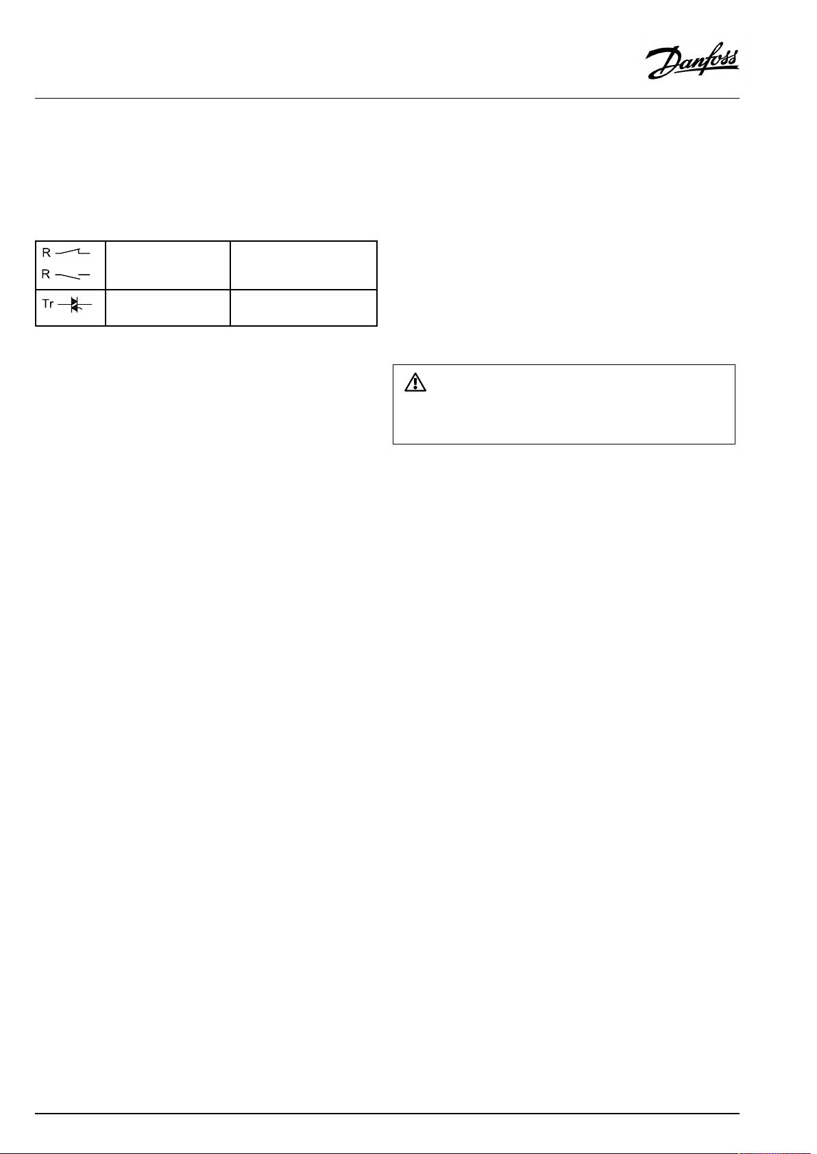
Maximumloadratings:
Relayterminals
4(2)A/230Va.c.
(4Aforohmicload,2Afor
inductiveload)
Triac(=electronic
0,2A/230Va.c.
relay)terminals
Wirecrosssection:0.5-1.5mm²
Incorrectconnectioncandamagetheelectronicoutputs.
Max.2x1.5mm²wirescanbeinsertedintoeachscrewterminal.
AQ000086455681en-010402
©Danfoss|2021.02|17
Page 18
OperatingGuideECLComfort310,applicationA361
2.5.2Electricalconnections24Va.c.
SeealsotheInstallationGuide(deliveredwiththeapplicationkey)
forapplicationspecificconnections.
Maximumloadratings:
Relayterminals
Triac(=electronic
relay)terminals
4(2)A/24Va.c.
(4Aforohmicload,2Afor
inductiveload)
1A/24Va.c.
Donotconnect230Va.c.poweredcomponentstoa24Va.c.power
suppliedcontrollerdirectly.Useauxilliaryrelays(K)toseparate230
Va.c.from24Va.c.
18|©Danfoss|2021.02
AQ000086455681en-010402
Page 19
OperatingGuideECLComfort310,applicationA361
2.5.3Electricalconnections,safetythermostats,ingeneral
SeealsotheInstallationGuide(deliveredwiththeapplicationkey)
forapplicationspecificconnections.
WhenSTisactivatedbyahightemperature,thesafetycircuitinthe
motorizedcontrolvalveclosesthevalveimmediately.
WhenST1isactivatedbyahightemperature(theTRtemperature),the
motorizedcontrolvalveisclosedgradually.Atahighertemperature
(theSTtemperature),thesafetycircuitinthemotorizedcontrolvalve
closesthevalveimmediately.
AQ000086455681en-010402
©Danfoss|2021.02|19
Page 20
OperatingGuideECLComfort310,applicationA361
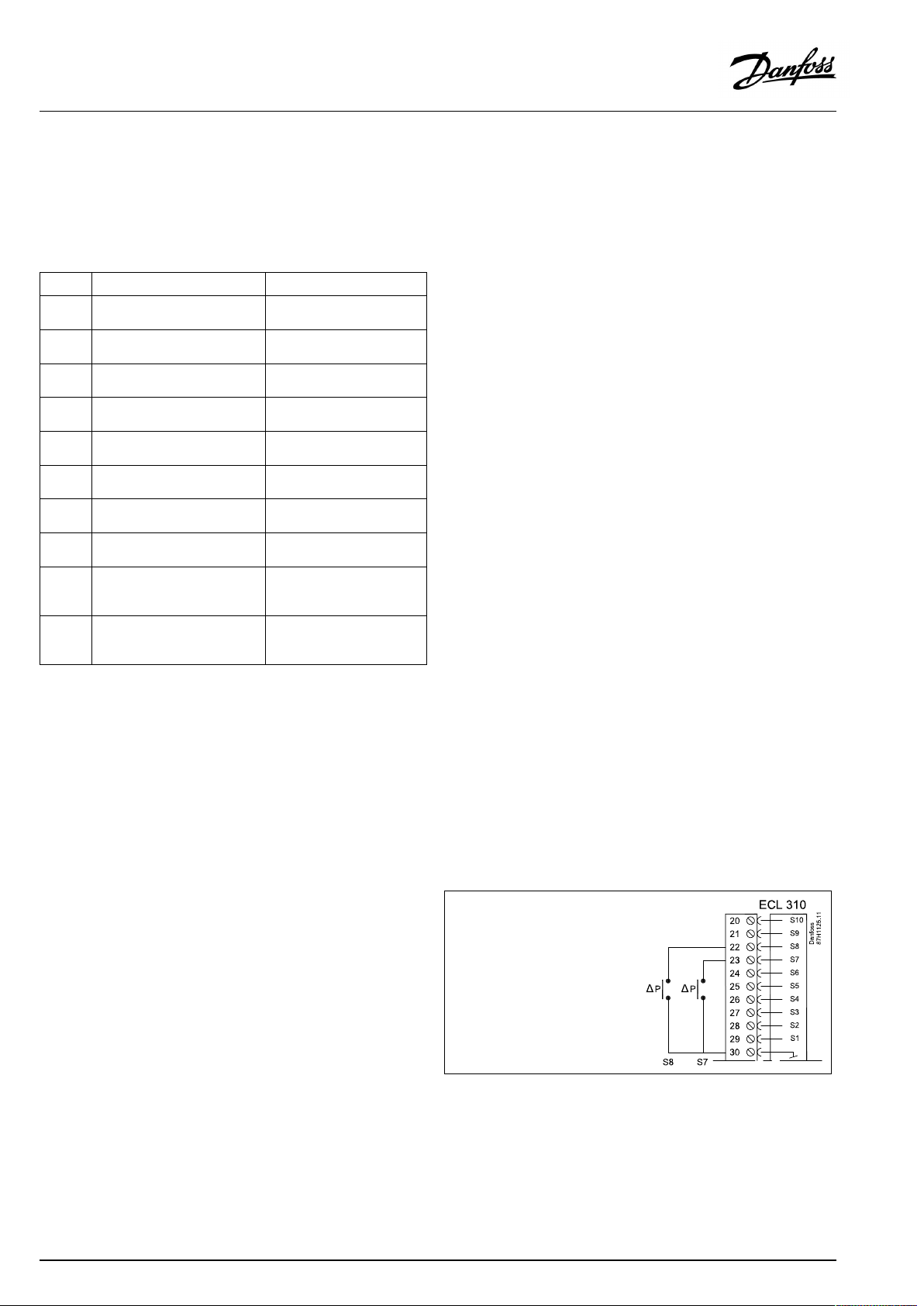
2.5.4Electricalconnections,Pt1000temperaturesensorsandsignals
SeetheInstallationGuide(deliveredwiththeapplicationkey)for
sensorandinputconnections.
A361.1/A361.2:
Sensor
S1
S2
S3
S4
S5Returntemperaturesensor,
S6Returntemperaturesensor,
S7
S8
S9
S10
*
**
***
Description
Outdoortemperature
sensor*
Supplyflowtemperature
sensor**
Flowtemperaturesensor***,
circuit1
Flowtemperaturesensor***,
circuit2
circuit1
circuit2
Differentialpressureswitch,
circuit1
Differentialpressureswitch,
circuit2
Pressuretransmitter(0–10
Vor4–20mA)orpressure
switch,circuit2
Pressuretransmitter(0–10
Vor4–20mA)orpressure
switch,circuit1
Iftheoutdoortemperaturesensorisnotconnectedorthe
cableisshort-circuited,thecontrollerassumesthatthe
outdoortemperatureis0(zero)°C.
OnlyforapplicationA361.2.
Theflowtemperaturesensormustalwaysbeconnected
inordertohavethedesiredfunctionality.Ifthesensoris
notconnectedorthecableisshort-circuited,themotorized
controlvalvecloses(safetyfunction).
Recommendedtype
ESMT
ESM-11/ESMB/
ESMC/ESMU
ESM-11/ESMB/
ESMC/ESMU
ESM-11/ESMB/
ESMC/ESMU
ESM-11/ESMB/
ESMC/ESMU
ESM-11/ESMB/
ESMC/ESMU
Connectionof2differentialpressureswitches
20|©Danfoss|2021.02
AQ000086455681en-010402
Page 21
OperatingGuideECLComfort310,applicationA361
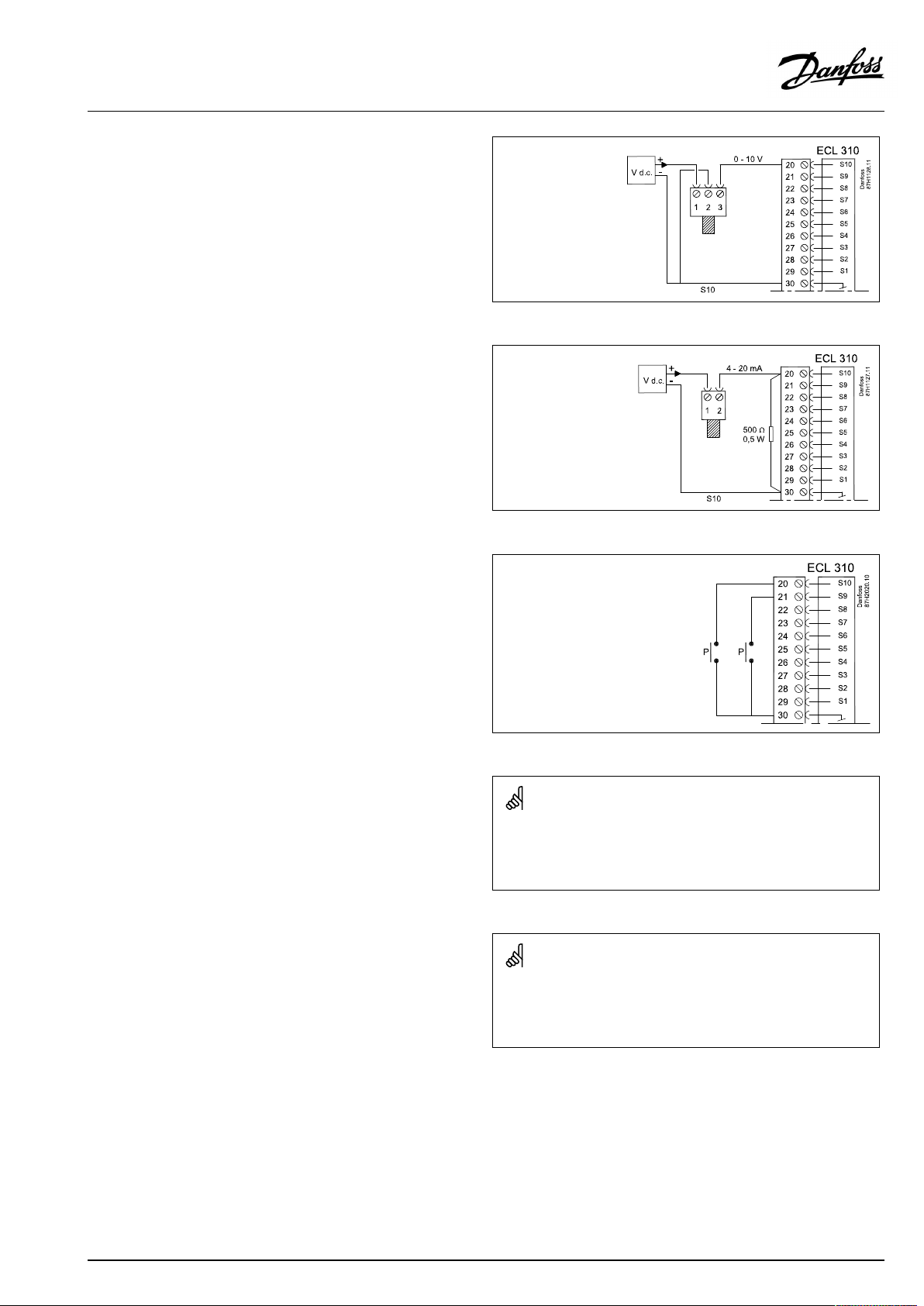
Connectionofapressuretransmitterwith0-10Voutput
ExampleofapressuretransmitterconnectiontoS10.Pressure
transmittercanbeconnectedinthesamewaytoS9.
Connectionofapressuretransmitterwith4-20mAoutput
The4-20mAsignalisconvertedtoa2-10Vsignalbymeansofthe
500ohmresistor.
ExampleofapressuretransmitterconnectiontoS10.Pressure
transmittercanbeconnectedinthesamewaytoS9.
Connectionof2pressureswitches
Wirecrosssectionforsensorconnections:Min.0.4mm².
Totalcablelength:Max.200m(allsensorsincl.internalECL485
communicationbus)
Cablelengthsofmorethan200mmaycausenoisesensibility(EMC).
Wirecrosssectionforsensorconnections:Min.0.4mm².
Totalcablelength:Max.200m(allsensorsincl.internalECL485
communicationbus).
Cablelengthsofmorethan200mmaycausenoisesensibility(EMC).
AQ000086455681en-010402
©Danfoss|2021.02|21
Page 22
OperatingGuideECLComfort310,applicationA361
2.5.5Electricalconnections,ECA30/31
Terminal
ECL
Terminal
ECA30/31
30
31
4
1
322
333
4
5
*
Afteranexternalroomtemperaturesensorhasbeenconnected,
Description
Twistedpair
Twistedpair
Ext.roomtemperature
sensor*
Type
(recomm.)
Cable2x
twistedpair
ESM-10
ECA30/31mustberepowered.
ThecommunicationtotheECA30/31mustbesetupintheECL
Comfortcontrollerin'ECAaddr.'
TheECA30/31mustbesetupaccordingly.
AfterapplicationsetuptheECA30/31isreadyafter2–5min.A
progressbarintheECA30/31isdisplayed.
Iftheactualapplicationcontainstwoheatingcircuits,itispossible
toconnectanECA30/31toeachcircuit.Theelectricalconnections
aredoneinparallel.
Max.2ECA30/31canbeconnectedtoanECLComfort310controller
ortoECLComfort210/296/310controllersinamaster-slavesystem.
SetupproceduresforECA30/31:Seesection‘Miscellaneous’ .
ECAinformationmessage:
‘Applicationreq.newerECA’:
Thesoftware(firmware)ofyourECAdoesnotcomplywiththe
software(firmware)ofyourECLComfortcontroller.Pleasecontact
yourDanfosssalesoffice.
Someapplicationsdonotcontainfunctionsrelatedtoactualroom
temperature.TheconnectedECA30/31willonlyfunctionasremote
control.
22|©Danfoss|2021.02
AQ000086455681en-010402
Page 23
OperatingGuideECLComfort310,applicationA361
2.5.6Electricalconnections,master/slavesystems
Thecontrollercanbeusedasmasterorslaveinmaster/slave
systemsviatheinternalECL485communicationbus(2xtwisted
paircable).
TheECL485communicationbusisnotcompatiblewiththeECL
businECLComfort110,200,300and301!
Totalcablelength:Max.200m(allsensorsincl.internalECL485
communicationbus).
Cablelengthsofmorethan200mmaycausenoisesensibility(EMC).
Terminal
Description
Type
(recomm.)
30
Commonterminal
+12V*,ECL485communicationbus
31
*OnlyforECA30/31andmaster/
slavecommunication
32
B,ECL485communicationbus
33
A,ECL485communicationbus
Cable2x
twistedpair
ECL485buscable
MaximumrecommendedlengthoftheECL485busiscalculatedlike
this:
Subtract"TotallengthofallinputcablesofallECLcontrollersinthe
master-slavesystem"from200m.
Simpleexamplefortotallengthofallinputcables,3xECL:
1xECL
3xECL
3xECLReturntemp.sensor:
3xECLRoomtemp.sensor:
Total:
Outdoortemp.sensor:
Flowtemp.sensor:
15m
18m
18m
30m
81m
2.5.7Electricalconnections,communication
Electricalconnections,Modbus
ECLComfort210:Non-galvanicisolatedModbusconnections
ECLComfort296:GalvanicisolatedModbusconnections
ECLComfort310:GalvanicisolatedModbusconnections
AQ000086455681en-010402
MaximumrecommendedlengthoftheECL485bus:
200-81m=119m
©Danfoss|2021.02|23
Page 24

OperatingGuideECLComfort310,applicationA361
2.5.8Electricalconnections,communication
Electricalconnections,M-bus
ECLComfort210:Notimplemented
ECLComfort296:Onboard,non-galvanicisolated.Max.cable
length50m.
ECLComfort310:Onboard,non-galvanicisolated.Max.cable
length50m.
24|©Danfoss|2021.02
AQ000086455681en-010402
Page 25
OperatingGuideECLComfort310,applicationA361
2.6InsertingtheECLApplicationKey
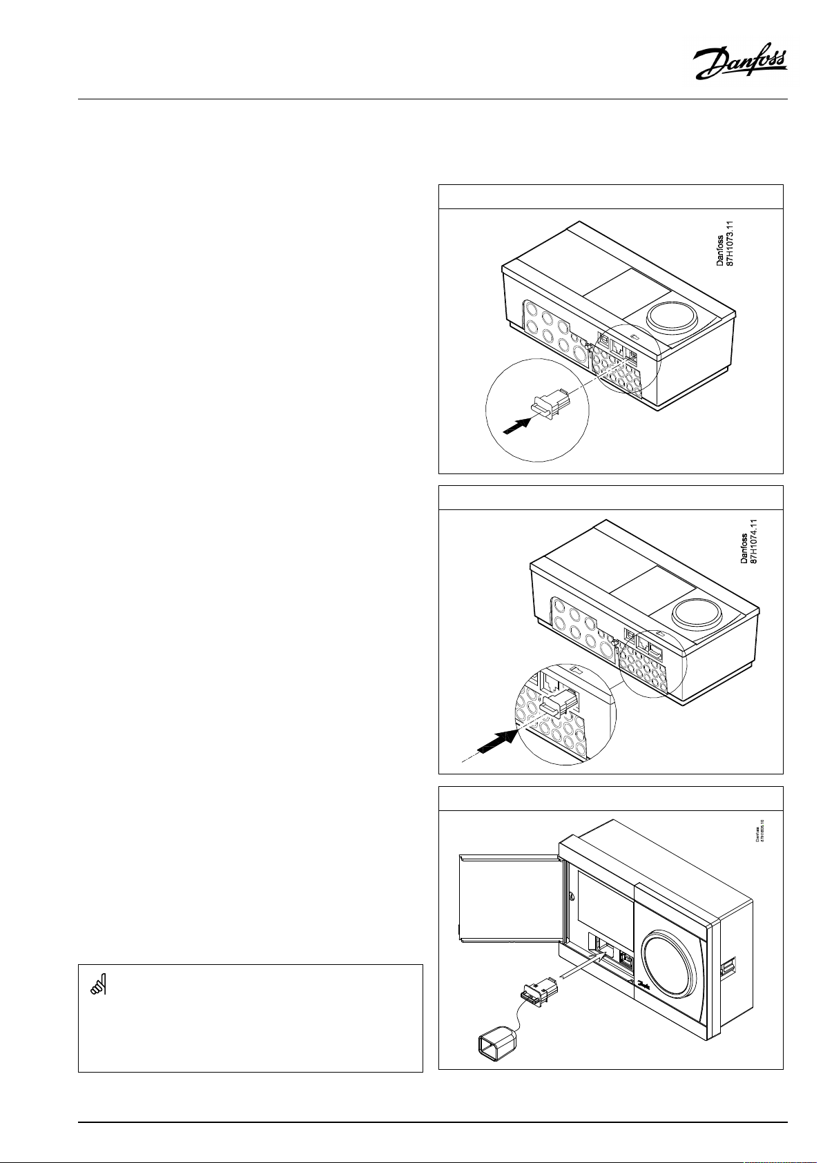
2.6.1InsertingtheECLApplicationKey
TheECLApplicationKeycontains
•theapplicationanditssubtypes,
•currentlyavailablelanguages,
•factorysettings:e.g.schedules,desiredtemperatures,
limitationvaluesetc.Itisalwayspossibletorecoverthefactory
settings,
•memoryforusersettings:specialuser/systemsettings.
Afterhavingpowered-upthecontroller,differentsituationsmight
beexisting:
1.Thecontrollerisnewfromthefactory,theECLApplicationKey
isnotinserted.
2.Thecontrolleralreadyrunsanapplication.TheECLApplication
Keyisinserted,buttheapplicationneedstobechanged.
3.Acopyofthecontrollerssettingsisneededforconfiguring
anothercontroller.
ECLComfort210/310
ECLComfort210/310
Usersettingsare,amongothers,desiredroomtemperature,desired
DHWtemperature,schedules,heatcurve,limitationvaluesetc.
Systemsettingsare,amongothers,communicationset-up,display
brightnessetc.
AQ000086455681en-010402
ECLComfort296
©Danfoss|2021.02|25
Page 26
OperatingGuideECLComfort310,applicationA361
Automaticupdateofcontrollersoftware(firmware):
Thesoftwareofthecontrollerisupdatedautomaticallywhenthekey
isinserted(asofcontrollerversion1.11(ECL210/310)andversion
1.58(ECL296)).Thefollowinganimationwillbeshownwhenthe
softwareisbeingupdated:
Progressbar
Duringupdate:
•DonotremovetheKEY
Ifthekeyisremovedbeforethehour-glassisshown,youhave
tostartafresh.
•Donotdisconnectthepower
Ifthepowerisinterruptedwhenthehour-glassisshown,the
controllerwillnotwork.
•Manualupdateofcontrollersoftware(firmware):
Seethesection"Automatic/manualupdateoffirmware"
The“Keyoverview”doesnotinform—throughECA30/31—about
thesubtypesoftheapplicationkey.
Keyinserted/notinserted,description:
ECLComfort210/310,controllerversionslowerthan1.36:
-
Takeouttheapplicationkey;for20minutes
settingscanbechanged.
-
Powerupthecontrollerwithoutthe
applicationkeyinserted;for20minutes
settingscanbechanged.
ECLComfort210/310,controllerversions1.36andup:
-
Takeouttheapplicationkey;for20minutes
settingscanbechanged.
-
Powerupthecontrollerwithoutthe
applicationkeyinserted;settingscannotbe
changed.
ECLComfort296,controllerversions1.58andup:
-
Takeouttheapplicationkey;for20minutes
settingscanbechanged.
-
Powerupthecontrollerwithoutthe
applicationkeyinserted;settingscannotbe
changed.
26|©Danfoss|2021.02
AQ000086455681en-010402
Page 27
OperatingGuideECLComfort310,applicationA361
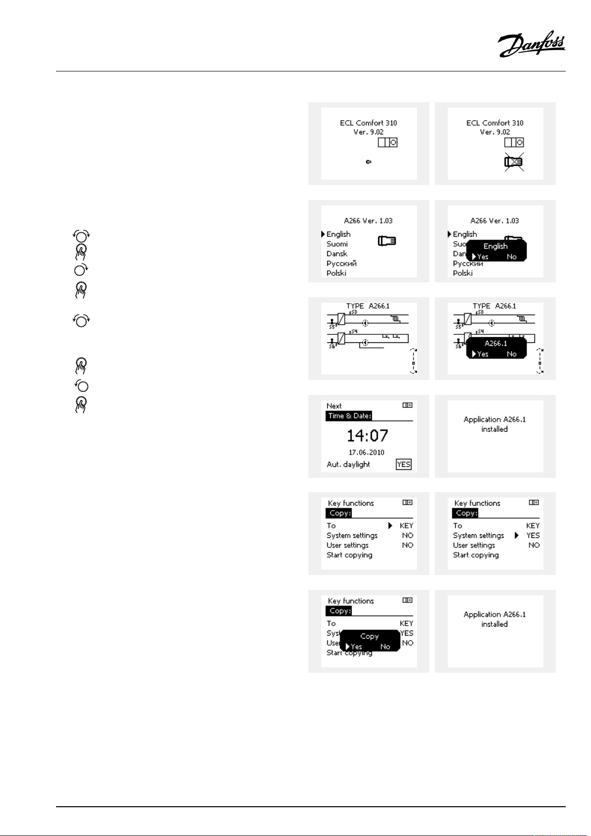
ApplicationKey:Situation1
Thecontrollerisnewfromthefactory,theECLApplicationKey
isnotinserted.
AnanimationfortheECLApplicationKeyinsertionisdisplayed.
InserttheApplicationKey.
ApplicationKeynameandVersionisindicated(example:A266
Ver.1.03).
IftheECLApplicationKeyisnotsuitableforthecontroller,a"cross"
isdisplayedovertheECLApplicationKey-symbol.
Action:Purpose:
Selectlanguage
Confirm
Selectapplication(subtype)
Somekeyshaveonlyoneapplication.
Confirmwith‘Yes’
Set'Time&Date'
Turnandpushthedialtoselectand
change'Hours' ,'Minutes','Date',
'Month'and'Year' .
Choose''Next'
Confirmwith‘Yes’
Goto‘Aut.daylight’
Choosewhether‘ Aut.daylight´*
shouldbeactiveornot
*‘Aut.daylight’istheautomaticchangeoverbetweensummer
andwintertime.
DependingonthecontentsoftheECLApplicationKey,procedure
AorBistakingplace:
A
TheECLApplicationkeycontainsfactorysettings:
Thecontrollerreads/transfersdatafromtheECLApplicationKey
toECLcontroller.
Examples:
YESorNO
Theapplicationisinstalled,andthecontrollerresetsandstartsup.
B
TheECLApplicationkeycontainschangedsystemsettings:
Pushthedialrepeatedly.
’NO’:
’YES*:
Ifthekeycontainsusersettings:
Pushthedialrepeatedly.
‘NO:
‘YES*:
*If‘YES’cannotbechosen,theECLApplicationKeydoesnot
containanyspecialsettings.
Choose‘Startcopying’andconfirmwith'Yes'.
AQ000086455681en-010402
OnlyfactorysettingsfromtheECLApplicationKeywill
becopiedtothecontroller.
Specialsystemsettings(differingfromthefactory
settings)willbecopiedtothecontroller.
OnlyfactorysettingsfromtheECLApplicationKeywill
becopiedtothecontroller.
Specialusersettings(differingfromthefactorysettings)
willbecopiedtothecontroller.
©Danfoss|2021.02|27
Page 28
OperatingGuideECLComfort310,applicationA361
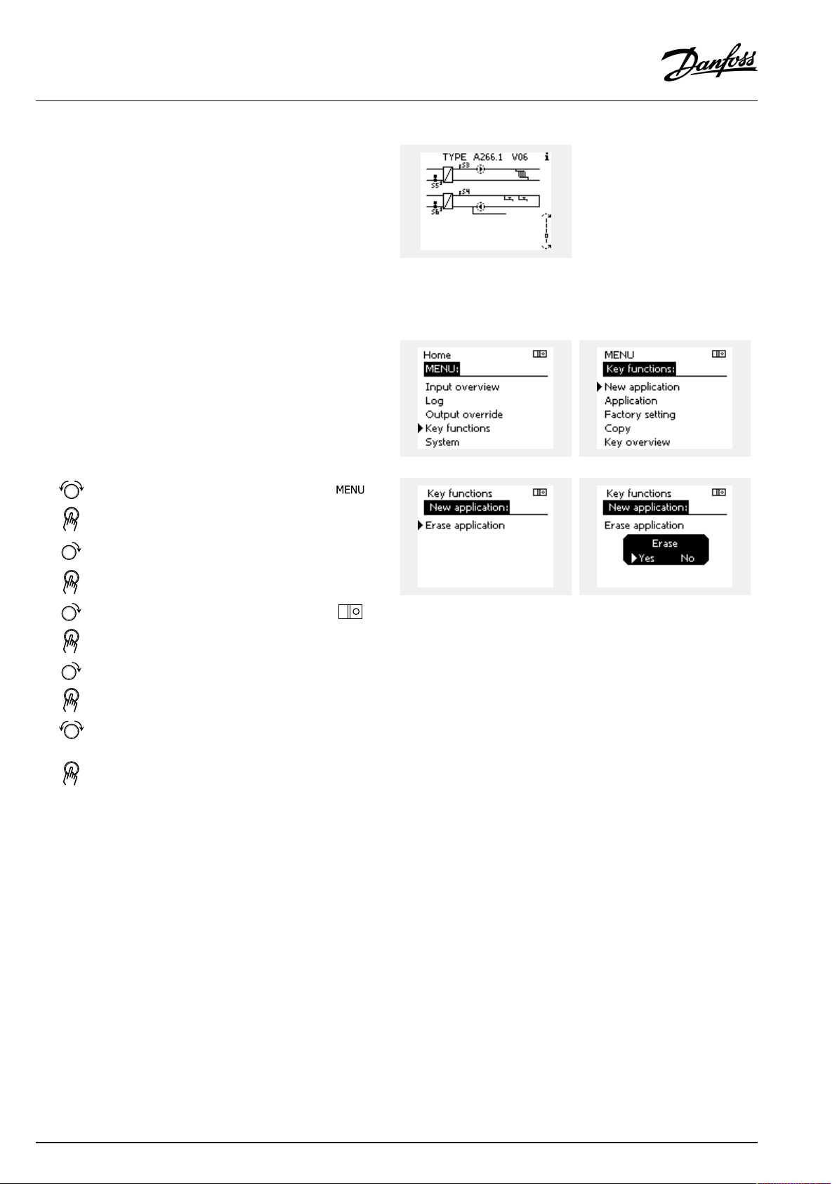
(Example):
The"i"intheupperrightcornerindicatesthat-besidesthefactory
settings-thesubtypealsocontainsspecialuser/systemssettings.
ApplicationKey:Situation2
Thecontrolleralreadyrunsanapplication.TheECLApplication
Keyisinserted,buttheapplicationneedstobechanged.
TochangetoanotherapplicationontheECLApplicationKey,the
currentapplicationinthecontrollermustbeerased(deleted).
BeawarethattheApplicationKeymustbeinserted.
Action:Purpose:
Choose‘MENU’inanycircuit
Confirm
Choosethecircuitselectoratthetop
rightcornerinthedisplay
Confirm
Choose‘Commoncontrollersettings’
Confirm
Choose‘Keyfunctions’
Confirm
Choose‘Eraseapplication’
Confirmwith‘Yes’
Thecontrollerresetsandisreadytobeconfigured.
Followtheproceduredescribedinsituation1.
Examples:
28|©Danfoss|2021.02
AQ000086455681en-010402
Page 29
OperatingGuideECLComfort310,applicationA361
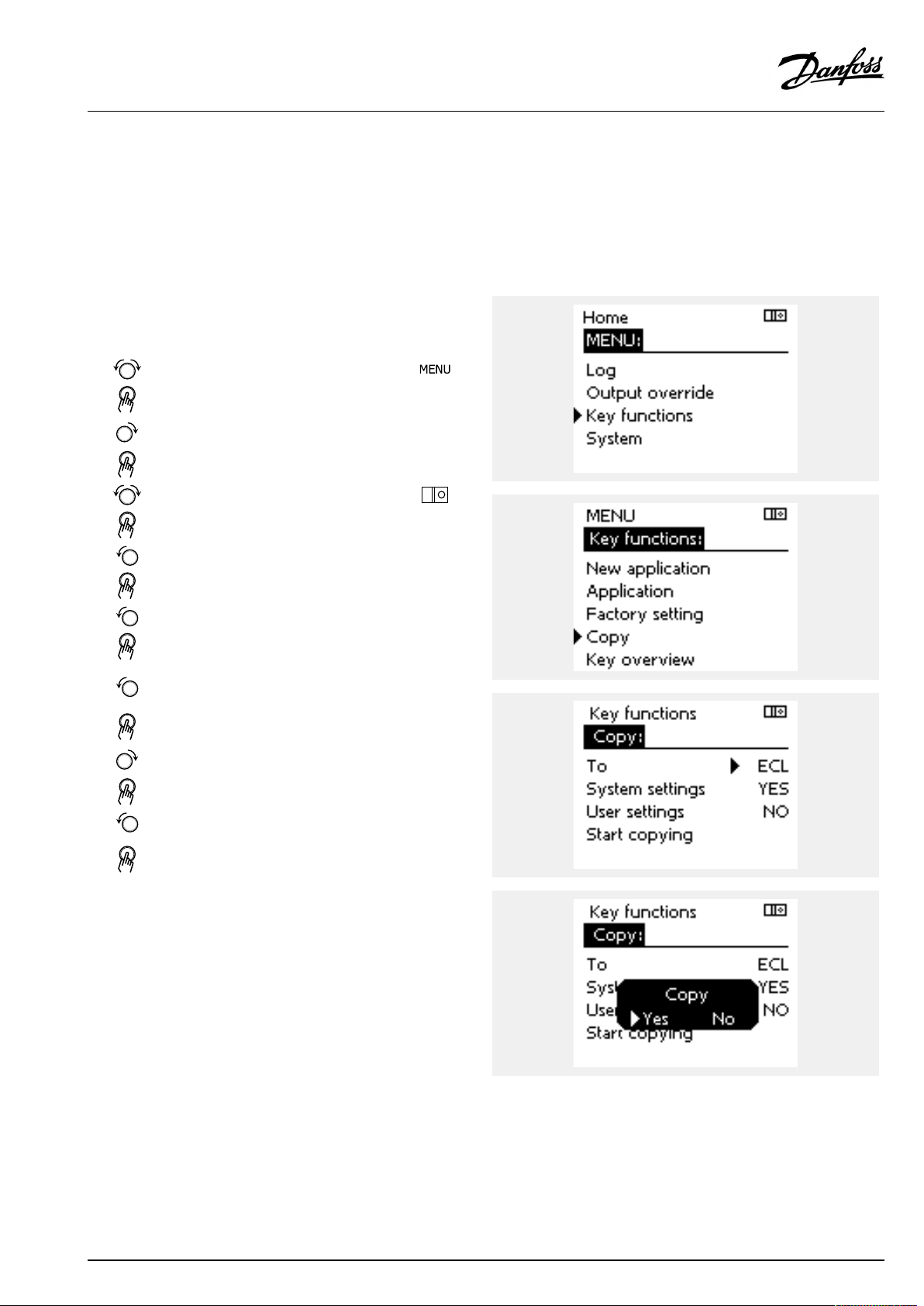
ApplicationKey:Situation3
Acopyofthecontrollerssettingsisneededforconfiguring
anothercontroller.
Thisfunctionisused
•forsaving(backup)ofspecialuserandsystemsettings
•whenanotherECLComfortcontrollerofthesametype(210,
296or310)mustbeconfiguredwiththesameapplicationbut
user/systemsettingsdifferfromthefactorysettings.
HowtocopytoanotherECLComfortcontroller:
Action:Purpose:
Choose‘MENU’
Confirm
Choosethecircuitselectoratthetop
rightcornerinthedisplay
Confirm
Choose'Commoncontrollersettings'
Confirm
Goto‘Keyfunctions’
Confirm
Choose‘Copy’
Confirm
Choose‘To’ .
‘ECL’or‘KEY’willbeindicated.Choose
’ECL’orKEY’
Pushthedialrepeatedlytochoose
copydirection
Choose‘Systemsettings’or‘User
settings’
Pushthedialrepeatedlytochoose
‘Yes’or‘No’in‘Copy’ .Pushtoconfirm.
Choose‘Startcopying’
TheApplicationKeyorthecontroller
isupdatedwithspecialsystemoruser
settings.
Examples:
*
’ECL’or‘KEY’ .
**
‘NO’or‘YES’
*
‘ECL’:
‘KEY’:
**
‘NO’:
‘YES’:
AQ000086455681en-010402
DatawillbecopiedfromtheApplicationKeytothe
ECLController.
DatawillbecopiedfromtheECLControllertothe
ApplicationKey.
ThesettingsfromtheECLcontrollerwillnotbecopied
totheApplicationKeyortotheECLComfortcontroller.
Specialsettings(differingfromthefactorysettings)will
becopiedtotheApplicationKeyortotheECLComfort
controller.IfYEScannotbechosen,therearenospecial
settingstobecopied.
©Danfoss|2021.02|29
Page 30
OperatingGuideECLComfort310,applicationA361
Language
Atapplicationupload,alanguagemustbeselected.*
IfanotherlanguagethanEnglishisselected,theselectedlanguage
ANDEnglishwillbeuploadedintotheECLcontroller.
ThismakesserviceeasyforEnglishspeakingservicepeople,just
becausetheEnglishlanguagemenuscanbevisiblebychanging
theactualsetlanguageintoEnglish.
(Navigation:MENU>Commoncontroller>System>Language)
Iftheuploadedlanguageisnotsuitable,theapplicationmustbe
erased.UserandSystemsettingscanbesavedontheapplication
keybeforeerasing.
Afternewuploadwithpreferredlanguage,theexistingUserand
Systemsettingscanbeuploaded.
*)
(ECLComfort310,24Volt)Iflanguagecannotbeselected,the
powersupplyisnota.c.(alternatingcurrent).
2.6.2ECLApplicationKey,copyingdata
Generalprinciples
Whenthecontrollerisconnectedandoperating,youcancheck
andadjustallorsomeofthebasicsettings.Thenewsettingscan
bestoredontheKey.
Factorysettingscanalwaysberestored.
HowtoupdatetheECLApplicationKeyaftersettingshave
beenchanged?
AllnewsettingscanbestoredontheECLApplicationKey.
Howtostorefactorysettinginthecontrollerfromthe
ApplicationKey?
PleasereadtheparagraphconcerningApplicationKey,Situation
1:Thecontrollerisnewfromthefactory,theECLApplicationKey
isnotinserted.
HowtostorepersonalsettingsfromthecontrollertotheKey?
PleasereadtheparagraphconcerningApplicationKey,Situation3:
Acopyofthecontrollerssettingsisneededforconfiguringanother
controller
Asamainrule,theECLApplicationKeyshouldalwaysremainin
thecontroller.IftheKeyisremoved,itisnotpossibletochange
settings.
Makeanoteofnewsettingsinthe'Settingsoverview'table.
DonotremovetheECLApplicationKeywhilecopying.Thedataon
theECLApplicationKeycanbedamaged!
ItispossibletocopysettingsfromoneECLComfortcontrollerto
anothercontrollerprovidedthatthetwocontrollersarefromthesame
series(210or310).
Furthermore,whentheECLComfortcontrollerhasbeenuploaded
withanapplicationkey,minimumversion2.44,itispossibletoupload
personalsettingsfromapplicationkeys,minimumversion2.14.
30|©Danfoss|2021.02
AQ000086455681en-010402
Page 31

OperatingGuideECLComfort310,applicationA361
The“Keyoverview”doesnotinform—throughECA30/31—about
thesubtypesoftheapplicationkey.
Keyinserted/notinserted,description:
ECLComfort210/310,controllerversionslowerthan1.36:
-
Takeouttheapplicationkey;for20minutes
settingscanbechanged.
-
Powerupthecontrollerwithoutthe
applicationkeyinserted;for20minutes
settingscanbechanged.
ECLComfort210/310,controllerversions1.36andup:
-
Takeouttheapplicationkey;for20minutes
settingscanbechanged.
-
Powerupthecontrollerwithoutthe
applicationkeyinserted;settingscannotbe
changed.
ECLComfort296,controllerversions1.58andup:
-
Takeouttheapplicationkey;for20minutes
settingscanbechanged.
-
Powerupthecontrollerwithoutthe
applicationkeyinserted;settingscannotbe
changed.
AQ000086455681en-010402
©Danfoss|2021.02|31
Page 32

OperatingGuideECLComfort310,applicationA361
2.7Checklist
IstheECLComfortcontrollerreadyforuse?
Makesurethatthecorrectpowersupplyisconnectedtoterminals9and10(230Vor24V).
Makesurethecorrectphaseconditionsareconnected:
230V:Live=terminal9andNeutral=terminal10
24V:SP=terminal9andSN=terminal10
Checkthattherequiredcontrolledcomponents(actuator,pumpetc.)areconnectedtothecorrectterminals.
Checkthatallsensors/signalsareconnectedtothecorrectterminals(see'Electricalconnections').
Mountthecontrollerandswitchonthepower.
IstheECLApplicationKeyinserted(see'InsertingtheApplicationKey').
DoestheECLComfortcontrollercontainanexistingapplication(see'InsertingtheApplicationKey').
Isthecorrectlanguagechosen(see'Language'in'Commoncontrollersettings').
Isthetime&datesetcorrectly(see'Time&Date'in'Commoncontrollersettings').
Istherightapplicationchosen(see'Identifyingthesystemtype').
Checkthatallsettingsinthecontroller(see'Settingsoverview')aresetorthatthefactorysettingscomplywithyour
requirements.
Choosemanualoperation(see'Manualcontrol').Checkthatvalvesopenandclose,andthatrequiredcontrolled
components(pumpetc.)startandstopwhenoperatedmanually.
Checkthatthetemperatures/signalsshowninthedisplaymatchtheactualconnectedcomponents.
Havingcompletedthemanualoperationcheck,choosecontrollermode(scheduled,comfort,savingorfrostprotection).
32|©Danfoss|2021.02
AQ000086455681en-010402
Page 33

OperatingGuideECLComfort310,applicationA361
2.8Navigation,ECLApplicationKeyA361
Navigation,applicationsA361,circuit1and2(*application361.2only)
Home
IDno.
MENU
ScheduleSelectableSelectable
Settings
Flowtemperature
11178
11177
11300
11301
11302
11303
Returnlimit
Flow/powerlimitActualActual
Optimization
Controlpar.
11031
11032
11033
11034
11035
11036
11037
11085
11119
11117
11118
11116
11112
11113
11109
11115
11011
11012
11013
11014
11026
11021
11179
11174
11184
11185
11186
11187
Circuit1,HeatingCircuit2,Heating
Function
HeatcurveHeatcurve
Temp.max.
Temp.min.
Highsupp.TX2*
HighTmaxY2*
LowsupplyTX1*
LowTmaxY1*
HighToutX1
LowlimitY1
LowToutX2
HighlimitY2
Infl.-max.
Infl.-min.
Adapt.time
Priority
LimitLimit
HighToutX1
LowlimitY1
LowToutX2
HighlimitY2
Adapt.time
Filterconstant
Inputtype
Units
Autosaving
Boost
Ramp
Optimizer
Prestop
Totalstop
Cut-out
Motorpr.
Xp
Tn
Mrun
Nz
IDno.
11178
12177
12300
12301
12302
12303
12031
12032
12033
12034
12035
12036
12037
12085
12119
12117
12118
12116
12112
12113
12109
12115
12011
12012
12013
12014
12026
12021
12179
12174
12184
12185
12186
12187
Function
Temp.max.
Temp.min.
Highsupp.TX2*
HighTmaxY2*
LowsupplyTX1*
LowTmaxY1*
HighToutX1
LowlimitY1
LowToutX2
HighlimitY2
Infl.-max.
Infl.-min.
Adapt.time
Priority
HighToutX1
LowlimitY1
LowToutX2
HighlimitY2
Adapt.time
Filterconstant
Inputtype
Units
Autosaving
Boost
Ramp
Optimizer
Prestop
Totalstop
Cut-out
Motorpr.
Xp
Tn
Mrun
Nz
AQ000086455681en-010402
©Danfoss|2021.02|33
Page 34

OperatingGuideECLComfort310,applicationA361
Navigation,applicationA361,circuit1andcircuit2continued
Home
MENU
Settings
HolidaySelectableSelectable
Alarm
InfluenceoverviewDes.flowT
Pumpcontrol
Refillwater
Application
Temp.monitor.
Clearalarm
AlarmoverviewSelectableSelectable
IDno.
11314
11310
11313
11311
11312
11022
11327
11323
11321
11322
11320
11325
11326
11017
11023
11052
11077
11078
11093
11141
11142
11189
11147
11148
11149
11150
11315
11324
Circuit1,HeatingCircuit2,Heating
Function
Chan.-overtime
Retrytime
Stab.time
Change,duration
Changetime
Pexercise
PressurePressure
Inputtype
Time-out
Pressure,des.
Pressure,diff.
Pexercise
Valvedelay
No.ofpumps
Demandoffset
Mexercise
DHWpriority
PfrostT
PheatT
Frostpr.T
Ext.input
Ext.mode
Min.act.time
Upperdifference
Lowerdifference
Delay
Lowesttemp.
Circ.pumps
Refillwater
Returnlim.Returnlim.
Flow/powerlim.Flow/powerlim.
HolidayHoliday
Ext.overrideExt.override
BoostBoost
RampRamp
Slave,demand
Heatingcut-outHeatingcut-out
DHWpriorityDHWpriority
IDno.
12314
12310
12313
12311
12312
12022
12327
12323
12321
12322
12320
12325
12326
12023
12052
12077
12078
12093
12141
12142
12189
12147
12148
12149
12150
12315
12324
Function
Chan.-overtime
Retrytime
Stab.time
Change,duration
Changetime
Pexercise
Inputtype
Time-out
Pressure,des.
Pressure,diff.
Pexercise
Valvedelay
No.ofpumps
Mexercise
DHWpriority
PfrostT
PheatT
Frostpr.T
Ext.input
Ext.mode
Min.act.time
Upperdifference
Lowerdifference
Delay
Lowesttemp.
Circ.pumps
Refillwater
34|©Danfoss|2021.02
AQ000086455681en-010402
Page 35

OperatingGuideECLComfort310,applicationA361
Navigation,applicationA361,Commoncontrollersettings(*applicationA361.2only)
Home
MENU
Time&Date
HolidaySelectable
Inputoverview1
Inputoverview2
Log1(sensors)
Log2(sensors)
Outputoverride
Keyfunctions
SystemECLversion
OutdoorTLogtoday
SupplyT*Logyesterday
Heatingflow&des.
HeatreturnT&limitLog4days
Staticpressure
OutdoorTLogtoday
SupplyT*Logyesterday
Heatingflow&des.
HeatreturnT&limitLog4days
Staticpressure
NewapplicationEraseapplication
Application
FactorysettingSystemsettings
Copy
Keyoverview
Extension
Ethernet
M-busconfig
EnergyMeters
Display
Communication
Language
Commoncontrollersettings
IDno.
60058
60059
38
2048
2150
2151
2050
Function
Selectable
OutdoorT
SupplyT*
HeatflowT
HeatreturnT
Staticpressure
S7status
OutdoorT
SupplyT*
HeatflowT
HeatreturnT
Staticpressure
S8status
Log2days
Log2days
M1,P1,P2,M2,P3,P5,V1,V2,
P4,A1
Usersettings
Gotofactory
To
Systemsettings
Usersettings
Startcopying
Codeno.
Hardware
Software
Buildno.
Serialno.
MAC
Productionweek
Selectable
Selectable
Backlight
Contrast
Modbusaddr.
ECL485addr.
Servicepin
Ext.reset
Language
AQ000086455681en-010402
©Danfoss|2021.02|35
Page 36

OperatingGuideECLComfort310,applicationA361
3.0Dailyuse
3.1Howtonavigate
Younavigateinthecontrollerbyturningthedialleftorrightto
thedesiredposition().
Thedialhasabuilt-inaccellerator.Thefasteryouturnthedial,the
fasteritreachesthelimitsofanywidesettingrange.
Thepositionindicatorinthedisplay(
youare.
Pushthedialtoconfirmyourchoices().
Thedisplayexamplesarefromatwo-circuitapplication:One
heatingcircuit()andonedomestichot-water(DHW)circuit().
Theexamplesmightdifferfromyourapplication.
)willalwaysshowyouwhere
ExampleshowsECL210/310
Heatingcircuit():DHWcircuit();
Somegeneralsettingswhichapplytotheentirecontrollerare
locatedinaspecificpartofthecontroller.
Toenter‘Commoncontrollersettings’:
Action:Purpose:
Choose‘MENU’inanycircuit
Confirm
Choosethecircuitselectoratthetop
rightcornerinthedisplay
Confirm
Choose‘Commoncontrollersettings’
Confirm
Examples:
Circuitselector
36|©Danfoss|2021.02
AQ000086455681en-010402
Page 37

OperatingGuideECLComfort310,applicationA361
3.2Understandingthecontrollerdisplay
ThissectiondescribesthefunctioningeneralfortheECLComfort
210/296/310series.Theshowndisplaysaretypicalandnot
applicationrelated.Theymightdifferfromthedisplaysinyour
application.
Choosingafavoritedisplay
Yourfavoritedisplayisthedisplayyouhavechosenasthedefault
display.Thefavoritedisplaywillgiveyouaquickoverviewofthe
temperaturesorunitsthatyouwanttomonitoringeneral.
Ifthedialhasnotbeenactivatedfor20min.,thecontrollerwill
reverttotheoverviewdisplayyouhavechosenasfavorite.
Toshiftbetweendisplays:Turnthedialuntilyoureachthedisplay
selector(
turntochooseyourfavoriteoverviewdisplay.Pushthedialagain.
)atthebottomrightsideofthedisplay.Pushthedialand
Heatingcircuit
Overviewdisplay1informsabout:
actualoutdoortemperature,controllermode,
actualroomtemperature,desiredroomtemperature.
Overviewdisplay2informsabout:
actualoutdoortemperature,trendinoutdoortemperature,
controllermode,max.andmin.outdoortemperaturessince
midnightaswellasdesiredroomtemperature.
Overviewdisplay3informsabout:
date,actualoutdoortemperature,controllermode,time,desired
roomtemperatureaswellasshowsthecomfortscheduleofthe
currentday.
Overviewdisplay4informsabout:
stateofthecontrolledcomponents,actualflowtemperature,
(desiredflowtemperature),controllermode,returntemperature
(limitationvalue),influenceondesiredflowtemperature.
ThevalueabovetheV2symbolindicates0–100%oftheanalogue
signal(0–10V).
Note:
Anactualflowtemperaturevaluemustbepresent,otherwisethe
circuit'scontrolvalvewillclose.
Overviewdisplay1:Overviewdisplay2:
Overviewdisplay3:Overviewdisplay4:
Exampleofoverviewdisplaywith
Influenceindication:
Example,favoritedisplay1in
A230.3,wheremin.desiredroom
temperatureisindicated(22.7):
Dependentonthechosendisplay,theoverviewdisplaysforthe
heatingcircuitinformyouabout:
•actualoutdoortemperature(-0.5)
•controllermode()
•actualroomtemperature(24.5)
•desiredroomtemperature(20.7°C)
•trendinoutdoortemperature(
)
•min.andmax.outdoortemperaturessincemidnight(
•date(23.02.2010)
•time(7:43)
•comfortscheduleofthecurrentday(0-12-24)
•stateofthecontrolledcomponents(M2,P2)
•actualflowtemperature(49°C),(desiredflowtemperature(31))
•returntemperature(24°C)(limitationtemperature(50))
AQ000086455681en-010402
)
©Danfoss|2021.02|37
Page 38

OperatingGuideECLComfort310,applicationA361
Settingthedesiredtemperature
Dependingonthechosencircuitandmode,itispossibletoenter
alldailysettingsdirectlyfromtheoverviewdisplays(seealsothe
nextpageconcerningsymbols).
Thesettingofthedesiredroomtemperatureisimportantevenifa
roomtemperaturesensor/RemoteControlUnitisnotconnected.
Ifthetemperaturevalueisdisplayedas
"--"
thesensorinquestionisnotconnected.
"---"
thesensorconnectionisshort-circuited.
Settingthedesiredroomtemperature
Thedesiredroomtemperaturecaneasilybeadjustedinthe
overviewdisplaysfortheheatingcircuit.
Action:Purpose:
Examples:
Desiredroomtemperature
Confirm
Adjustthedesiredroomtemperature
Confirm
Thisoverviewdisplayinformsaboutoutdoortemperature,actual
roomtemperatureaswellasdesiredroomtemperature.
Thedisplayexampleisforcomfortmode.Ifyouwanttochange
thedesiredroomtemperatureforsavingmode,choosethemode
selectorandselectsaving.
20.5
21.0
38|©Danfoss|2021.02
Thesettingofthedesiredroomtemperatureisimportantevenifa
roomtemperaturesensor/RemoteControlUnitisnotconnected.
AQ000086455681en-010402
Page 39

OperatingGuideECLComfort310,applicationA361
Settingthedesiredroomtemperature,ECA30/ECA31
Thedesiredroomtemperaturecanbesetexactlyasinthe
controller.However,othersymbolscanbepresentinthedisplay
(pleasesee'Whatdothesymbolsmean?').
WiththeECA30/ECA31youcanoverridethedesiredroom
temperaturesetinthecontrollertemporarilybymeansoftheoverride
functions:
AQ000086455681en-010402
©Danfoss|2021.02|39
Page 40
OperatingGuideECLComfort310,applicationA361
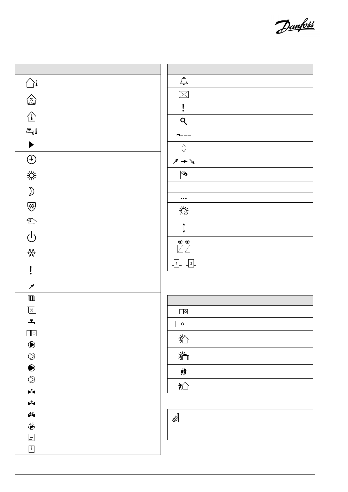
3.3Ageneraloverview:Whatdothesymbolsmean?
Symbol
Description
Outdoortemp.
Relativehumidityindoor
Roomtemp.
DHWtemp.
Positionindicator
Scheduledmode
Comfortmode
Savingmode
Frostprotectionmode
Manualmode
Standby
Coolingmode
Symbol
Temperature
Mode
Description
Alarm
Letter
Event
Monitoringtemperaturesensor
connection
Displayselector
Max.andmin.value
Trendinoutdoortemperature
Windspeedsensor
Sensornotconnectedornotused
Sensorconnectionshort-circuited
Fixedcomfortday(holiday)
Activeinfluence
Heatingactive(+)
Coolingactive(-)
Activeoutputoverride
Optimizedstartorstoptime
Heating
Cooling
DHW
Commoncontrollersettings
PumpON
PumpOFF
FanON
FanOFF
Actuatoropens
Actuatorcloses
Actuator,analoguecontrol
signal
Pump/fanspeed
DamperON
Circuit
Controlled
component
Numberofheatexchangers
Additionalsymbols,ECA30/31:
Symbol
InECA30/31onlythesymbolsthatarerelevanttotheapplicationin
thecontrolleraredisplayed.
Description
ECARemoteControlUnit
Connectionaddress(master:15,slaves:1-9)
15
Dayoff
Holiday
Relaxing(extendedcomfortperiod)
Goingout(extendedsavingperiod)
40|©Danfoss|2021.02
DamperOFF
AQ000086455681en-010402
Page 41

OperatingGuideECLComfort310,applicationA361
3.4Monitoringtemperaturesandsystemcomponents
ThissectiondescribesthefunctioningeneralfortheECLComfort
210/296/310series.Theshowndisplaysaretypicalandnot
applicationrelated.Theymightdifferfromthedisplaysinyour
application.
Heatingcircuit
Theoverviewdisplayintheheatingcircuitensuresaquick
overviewoftheactualand(desired)temperaturesaswellasthe
actualstateofthesystemcomponents.
Displayexample:
49°C
(31)
24°C
(50)
Inputoverview
Anotheroptiontogetaquickoverviewofmeasuredtemperatures
isthe'Inputoverview'whichisvisibleinthecommoncontroller
settings(howtoenterthecommoncontrollersettings,see
‘Introductiontocommoncontrollersettings’ .)
Asthisoverview(seedisplayexample)onlystatesthemeasured
actualtemperatures,itisread-only.
Flowtemperature
Desiredflowtemperature
Returntemperature
Returntemperaturelimitation
AQ000086455681en-010402
©Danfoss|2021.02|41
Page 42

OperatingGuideECLComfort310,applicationA361
3.5Influenceoverview
ThissectiondescribesthefunctioningeneralfortheECLComfort
210/296/310series.Theshowndisplaysaretypicalandnot
applicationrelated.Theymightdifferfromthedisplaysinyour
application.
Themenugivesanoverviewoftheinfluencesonthedesired
flowtemperature.Itdiffersfromapplicationtoapplicationwhich
parametersarelisted.Itcanbehelpfulinaservicesituationto
explainunexpectedconditionsortemperaturesamongothers.
Ifthedesiredflowtemperatureisinfluenced(corrected)byoneor
moreparameters,itisindicatedbyasmalllinewitharrow-down,
arrow-upordouble-arrow:
Arrow-down:
Theparameterinquestionreducesthedesiredflowtemperature.
Arrow-up:
Theparameterinquestionincreasesthedesiredflowtemperature.
Double-arrow:
Theparameterinquestioncreatesanoverride(e.g.Holiday).
Straightline:
Noactiveinfluence.
Intheexample,thearrowinthesymbolpointsdownwardsfor
'Roomlim. ' .Thismeansthattheactualroomtemperatureis
higherthanthedesiredroomtemperaturewhichagainresultsina
decreaseofthedesiredflowtemperature.
ExampleofoverviewdisplaywithInfluenceindication:
42|©Danfoss|2021.02
AQ000086455681en-010402
Page 43

OperatingGuideECLComfort310,applicationA361
3.6Manualcontrol
ThissectiondescribesthefunctioningeneralfortheECLComfort
210/296/310series.Theshowndisplaysaretypicalandnot
applicationrelated.Theymightdifferfromthedisplaysinyour
application.
Itispossibletomanuallycontroltheinstalledcomponents.
Manualcontrolcanonlybeselectedinfavoritedisplaysinwhich
thesymbolsforthecontrolledcomponents(valve,pumpetc.)are
visible.
Action:Purpose:
Choosemodeselector
Confirm
Choosemanualmode
Confirm
Choosepump
Confirm
SwitchONthepump
SwitchOFFthepump.
Confirmpumpmode
Choosemotorizedcontrolvalve
Confirm
Openthevalve
Stopopeningthevalve
Closethevalve
Examples:
ControlledcomponentsCircuitselector
Duringmanualoperation:
•Allcontrolfunctionsaredeactivated
•Outputoverrideisnotpossible
•Frostprotectionisnotactive
Stopclosingthevalve
Confirmvalvemode
Toleavemanualcontrol,usethemodeselectortoselectthe
desiredmode.Pushthedial.
Manualcontrolistypicallyusedwhencommisioningthe
installation.Thecontrolledcomponents,valve,pumpetc.,canbe
controlledforcorrectfunction.
AQ000086455681en-010402
Whenmanualcontrolisselectedforonecircuit,itisautomatically
selectedforallcircuits!
©Danfoss|2021.02|43
Page 44

OperatingGuideECLComfort310,applicationA361
3.7Schedule
3.7.1Setyourschedule
ThissectiondescribesthescheduleingeneralfortheECLComfort
210/296/310series.Theshowndisplaysaretypicalandnot
applicationrelated.Theymightdifferfromthedisplaysinyour
application.Insomeapplications,however,theremightbemore
thanoneschedule.Additionalschedulescanbefoundin‘Common
controllersettings’ .
Thescheduleconsistsofa7-dayweek:
=
M
Monday
=
T
Tuesday
=
W
Wednesday
=
T
Thursday
=
F
Friday
=
S
Saturday
=
S
Sunday
Theschedulewillday-by-dayshowyouthestartandstoptimesof
yourcomfortperiods(heating/DHWcircuits).
Changingyourschedule:
Action:
Purpose:
Choose'MENU'inanyoftheoverview
displays
Confirm
Confirmthechoice'Schedule'
Choosethedaytochange
Confirm*
GotoStart1
Confirm
Adjustthetime
Confirm
GotoStop1,Start2etc.etc.
Returnto'MENU'
Confirm
Choose'Yes'or'No'in'Save'
Confirm
Examples:
*Severaldayscanbemarked
Thechosenstartandstoptimeswillbevalidforallthechosendays
(inthisexampleThursdayandSaturday).
Youcansetmax.3comfortperiodsaday.Youcandeleteacomfort
periodbysettingstartandstoptimestothesamevalue.
44|©Danfoss|2021.02
Eachcircuithasitsownschedule.Tochangetoanothercircuit,goto
'Home',turnthedialandchoosethedesiredcircuit.
Thestartandstoptimescanbesetinhalf-hourly(30min.)intervals.
AQ000086455681en-010402
Page 45

OperatingGuideECLComfort310,applicationA361
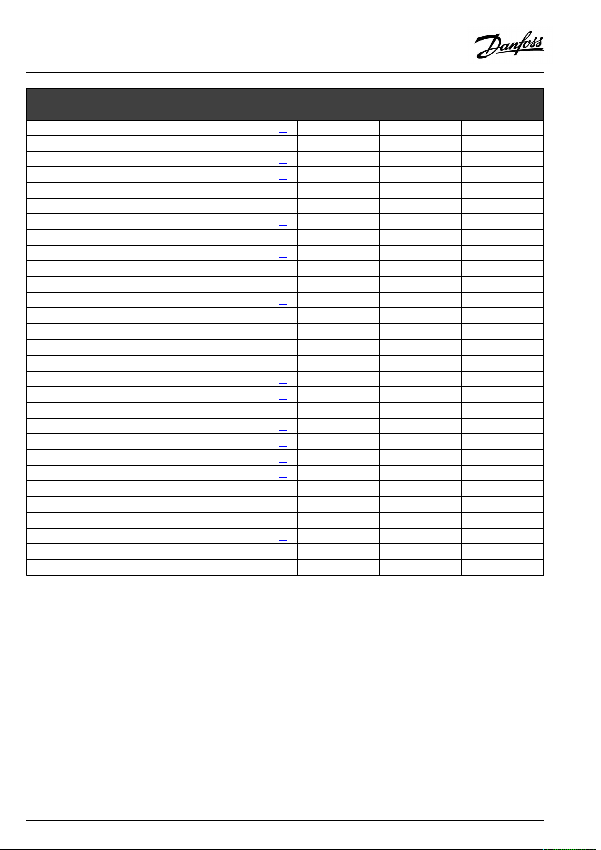
4.0Settingsoverview
Forfactorysettingsandsettingrange,seeappendix“ParameterIDoverview” .
ParametersindicatedwithanIDno.like"1x607"meanauniversalparameter.xstandsforcircuit/parametergroup.
SettingIDPage
Heatcurve
Heatcurve
Actual(actualfloworpower)
Pressure
Pressure,des.(desiredpressure)
Autosaving(savingtemp.dependentonoutdoortemp.)
Boost
Ramp(referenceramping)
Optimizer(optimizingtimeconstant)
Demandoffset
Totalstop
Pexercise(pumpexercise)
Mexercise(valveexercise)
Pre-stop(optimizedstoptime)
HighToutX1(returntemp.limitation,highlimit,X-axis)
LowlimitY1(returntemp.limitation,lowlimit,Y-axis)
LowToutX2(returntemp.limitation,lowlimit,X-axis)
HighlimitY2(returntemp.limitation,highlimit,Y-axis)
Infl.-max.(returntemp.limitation-max.influence)
Infl.-min.(returntemp.limitation-min.influence)
Adapt.time(adaptationtime)
DHWpriority(closedvalve/normaloperation)
PfrostT(circulationpump,frostprotectiontemp.)
PheatT(heatdemand)
Priority(priorityforreturntemp.limitation)
Frostpr.T(frostprotectiontemp.)
Inputtype
Limit(limitationvalue)
Adapt.time(adaptationtime)
Filterconstant
Units
HighlimitY2(flow/powerlimitation,highlimit,Y-axis)
LowlimitY1(flow/powerlimitation,lowlimit,Y-axis)
LowToutX2(flow/powerlimitation,lowlimit,X-axis)
HighToutX1(flow/powerlimitation,highlimit,X-axis)
Ext.input(externaloverride)
Ext.mode(externaloverridemode)
Upperdifference
1x01161
1x01262
1x01363
1x01463
1x01779
1x02164
1x022
1x02379
1x02665
1x031
1x032
1x033
1x034
1x035
1x036
1x037
1x05279
1x07780
1x07880
1x08556
1x09380
1x10958
1x111
1x11258
1x11359
1x115
1x11659
1x117
1x11860
1x11960
1x141
1x14281
1x147
Factorysettingsincircuit(s)
1
48
50
58
74
75
71
54
54
54
55
55
55
55
58
59
60
80
85
23
AQ000086455681en-010402
©Danfoss|2021.02|45
Page 46
OperatingGuideECLComfort310,applicationA361
SettingIDPage
Lowerdifference
Delay,example
Lowesttemp.
Motorpr.(motorprotection)
Temp.min.
Temp.max.
Summer,cut-out(limitforheatingcut-out)
Xp(proportionalband)
Tn(integrationtimeconstant)
Mrun(runningtimeofthemotorizedcontrolvalve)
Nz(neutralzone)
Min.act.time(min.activationtimegearmotor)
Highsupp.TX2(highvalueofsupplytemp.)
HighTmaxY2(highvalueofmaxlimitation)
LowsupplyTX1(lowvalueofsupplytemp.)
LowTmaxY1(lowvalueofmaxlimitation)
Retrytime
Change,duration
Changetime(changeovertime)
Stab.time(stabilizationtime)
Chan.-overtime(change-overtime)
Circ.pumps
Pexercise(pumpexercise)
Pressure,diff.(switchingdifference)
Time-out
Refillwater
Valvedelay
No.ofpumps
Inputtype
1x14885
1x14985
1x15086
1x174
1x17751
1x178
1x17966
1x18468
1x18569
1x18669
1x18769
1x18983
1x300
1x301
1x302
1x30352
1x310
1x311
1x31272
1x31372
1x31472
1x31586
1x320
1x322
1x323
1x32486
1x32576
1x326
1x327
Factorysettingsincircuit(s)
1
68
51
51
51
51
71
71
75
75
75
77
77
23
46|©Danfoss|2021.02
AQ000086455681en-010402
Page 47

OperatingGuideECLComfort310,applicationA361
5.0Settings
5.1IntroductiontoSettings
Descriptionsofsettings(parameter'sfunctions)aredividedinto
groupsasusedintheECLComfort210/296/310controller's
menustructure.Examples:"Flowtemperature" ,"Roomlimit"and
soon.Eachgroupstartswithageneralexplanation.
Thedescriptionsofeachparameterareinnumericorder,relatedto
theparameter'sIDnumbers.Youmightcomeacrossdifferences
betweentheorderinthisOperatingGuideandtheECLComfort
210/296/310controllers.
Someparameterdescriptionsarerelatedtospecificapplication
subtypes.Thismeansthatyoumightnotseetherelatedparameter
intheactualsubtypeintheECLcontroller.
Thenote"SeeAppendix… "referstotheAppendixattheendof
thisOperatingGuide,whereparameter'ssettingrangesandfactory
settingsarelisted.
Thenavigationhints(forexampleMENU>Settings>Returnlimit
…)covermultiplesubtypes.
AQ000086455681en-010402
©Danfoss|2021.02|47
Page 48

OperatingGuideECLComfort310,applicationA361
5.2Flowtemperature
TheECLComfortcontrollerdeterminesandcontrolstheflow
temperaturerelatedtotheoutdoortemperature.Thisrelationship
iscalledtheheatcurve.
Theheatcurveissetbymeansof6coordinatepoints.Thedesired
flowtemperatureissetat6pre-definedoutdoortemperature
values.
Theshownvaluefortheheatcurveisanaveragevalue(slope),
basedontheactualsettings.
Desiredflowtemperature
Outdoor
temp.
Desiredflowtemp.
A
BC
Your
settings
-30°C45°C75°C95°C
-15°C40°C60°C90°C
-5°C35°C50°C80°C
0°C32°C45°C70°C
5°C30°C40°C60°C
15°C25°C28°C35°C
A:Exampleforfloorheating
B:Factorysettings
C:Exampleforradiatorheating(highdemand)
MENU>Settings>Flowtemperature
Heatcurve
1
0.1...4.01.0
Theheatcurvecanbechangedintwoways:
1.Thevalueoftheslopeischanged(seeheatcurveexamples
onnextpage)
2.Thecoordinatesoftheheatcurvearechanged
Changethevalueoftheslope:
Pushthedialtoenter/changetheslopevalueoftheheatcurve
(example:1.0).
Whentheslopeoftheheatcurveischangedbymeansoftheslope
value,thecommonpointforallheatcurveswillbeadesiredflow
temperature=24.6°Catanoutdoortemperature=20°Canda
desiredroomtemperature=20.0°C.
Slopechanges
Coordinatechanges
Changethecoordinates:
Pushthedialtoenter/changethecoordinatesoftheheatcurve
(example:-30,75).
Theheatcurverepresentsthedesiredflowtemperaturesat
differentoutdoortemperaturesandatadesiredroomtemperature
of20°C.
Ifthedesiredroomtemperatureischanged,thedesiredflow
temperaturealsochanges:
(DesiredroomT-20)×HC×2.5
where"HC"istheHeatCurveslopeand"2.5"isaconstant.
48|©Danfoss|2021.02
Thecalculatedflowtemperaturecanbeinfluencedbythe‘Boost’and
‘Ramp’functionsetc.
Example:
Heatcurve:
Desiredflowtemp.:
Desiredroomtemp.:
Calculation(22–20)×1.0×2.5=
Result:
Thedesiredflowtemperaturewillbecorrectedfrom50°Cto55°C.
1.0
50°C
22°C
5
AQ000086455681en-010402
Page 49

OperatingGuideECLComfort310,applicationA361
Choosingaheatcurveslope
Theheatcurvesrepresentthedesiredflowtemperatureatdifferentoutdoortemperaturesandatadesiredroomtemperatureof20°C.
Thesmallarrows()indicate6differentoutdoortemperaturevaluesatwhichyoucanchangetheheatcurve.
Max.limitationofthedesiredflowtemperature:
IntheapplicationA361.1themax.limitationvalueisselectable
in‘Temp.max. ’ .
Max.limitationofthedesiredflowtemperature:
IntheapplicationA361.2thedesiredflowtemperatureormax.
limitationvaluedependsonthesupplytemperature(S2).The
relationshipissetinthefoursettings‘Highsupp.TX2’ ,‘HighTmax
Y2’ ,‘LowsupplyTX1’and‘LowTmaxY1’ .
Whensettingtheheatcurvecoordinatesasdescribedinthe
section'A361.1’ ,thedesiredflowtemperaturecanbelimitedtoa
maximumaccordingtothesupplytemperature(S2).
AQ000086455681en-010402
©Danfoss|2021.02|49
Page 50
OperatingGuideECLComfort310,applicationA361
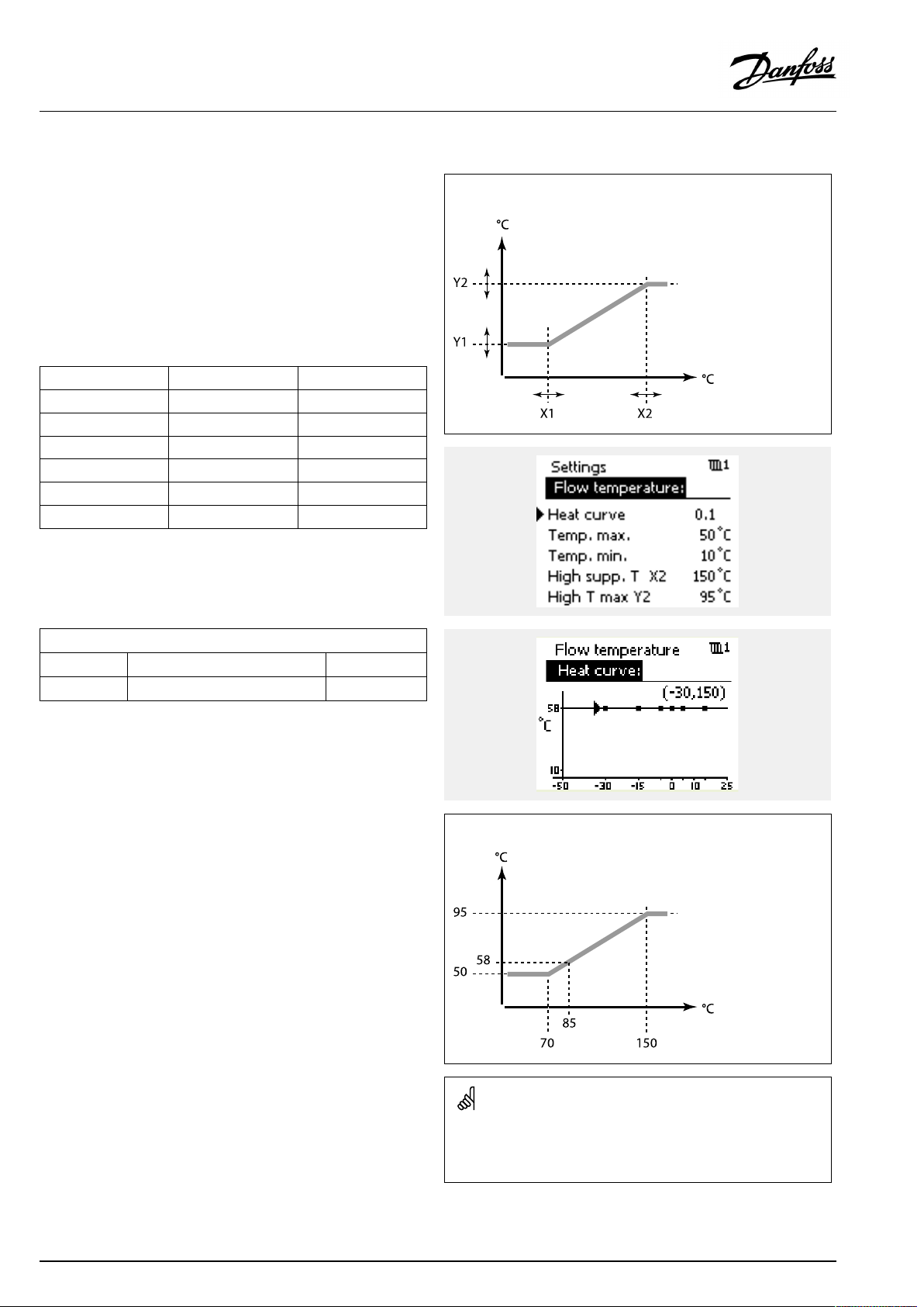
5.2.1A361.2
TheECLComfortcontrollerdeterminesandcontrolstheflow
temperaturerelatedtothesupplytemperature(S2).This
relationshipissetinthecontroller.
Theheatcurveissetinallcoordinatepointstothemax.desired
flowtemperature(150°C).Thedesiredflowtemperaturewill
alwaysbeinrelationtothesupplytemperature(S2).
Theshownvaluefortheheatcurveisanaveragevalue(slope),
basedontheactualsettings.
Outdoortemp.
FactorysettingY oursettings
-30°C150°C
-15°C150°C
-5°C150°C
0°C150°C
5°C150°C
15°C150°C
Adjustthedesiredflowtemperatureat-30,-15,-5,0,5,and15°C,
ifrequired.
MENU>Settings>Flowtemperature
Desiredflowtemperature
Supplytemp.(S2)
Heatcurve
CircuitSettingrange
1
Read-outonly
Factorysetting
Thefactorysetting(ageneraldesiredflowtemperatureof150°C)is
limitedtoamax.valuebasedonthesupplytemperature(S2)and
thesettingsinparameters‘Highsupp.TX2’ ,‘HighTmaxY2’ ,‘Low
supplyTX1’and‘LowTmaxY1’ .
Desiredflowtemperature
Supplytemp.(S2)
50|©Danfoss|2021.02
Theaboveheatcurveisanexampleofasupplytemperature(S2)of
85°C.Thedesiredflowtemperature(58°C)isbasedontheset-upof
therelationshipbetweenthesupplytemperature(S2)andthedesired
flowtemperature.
AQ000086455681en-010402
Page 51

OperatingGuideECLComfort310,applicationA361
ParametersindicatedwithanIDno.like"1x607"meanauniversal
parameter.
xstandsforcircuit/parametergroup.
MENU>Settings>Flowtemperature
Temp.min.
1x177
SeeAppendix“ParameterIDoverview”
Setthemin.flowtemperatureforthesystem.Thedesiredflow
temperaturewillnotbelowerthanthissetting.Adjustthefactory
setting,ifrequired.
MENU>Settings>Flowtemperature
Temp.max.
1x178
SeeAppendix“ParameterIDoverview”
Setthemax.flowtemperatureforthesystem.Thedesired
temperaturewillnotbehigherthanthissetting.Adjustthefactory
setting,ifrequired.
MENU>Settings>Flowtemperature
Highsupp.TX2(highvalueofsupplytemp.)
1x300
‘Temp.min.’isoverruledif'Totalstop'isactiveinSavingmodeor
'Cut-out'isactive.
‘Temp.min.’canbeoverruledbytheinfluencefromthereturn
temperaturelimitation(see'Priority').
Thesettingfor‘Temp.max. ’hashigherprioritythan‘Temp.min.’ .
Thesettingof‘heatcurve’ispossibleforheatingcircuitsonly.
Thesettingfor‘Temp.max. ’hashigherprioritythan‘Temp.min.’ .
SeeAppendix“ParameterIDoverview”
Setthehighvalueforthesupplytemperatureinrelationtothe
desiredmax.flowtemperature.Whenthesupplytemperatureis
abovethesetvalue,themax.limitationoftheflowtemperatureis
theY2value.Whenthesupplytemperatureisbelowthesetvalue,
themax.limitationoftheflowtemperaturewillbelower.
MENU>Settings>Flowtemperature
HighTmaxY2(highvalueofmaxlimitation)
1x301
SeeAppendix“ParameterIDoverview”
Setthehighvalueforthemax.limitationofthedesiredflow
temperature.
AQ000086455681en-010402
©Danfoss|2021.02|51
Page 52

OperatingGuideECLComfort310,applicationA361
MENU>Settings>Flowtemperature
LowsupplyTX1(lowvalueofsupplytemp.)
1x302
SeeAppendix“ParameterIDoverview”
Setthelowvalueforthesupplytemperatureinrelationtothe
desiredmax.flowtemperature.Whenthesupplytemperatureis
belowthesetvalue,themax.limitationoftheflowtemperatureis
theY1value.Whenthesupplytemperatureisabovethesetvalue,
themax.limitationoftheflowtemperaturewillbehigher.
MENU>Settings>Flowtemperature
LowTmaxY1(lowvalueofmaxlimitation)
1x303
SeeAppendix“ParameterIDoverview”
Setthelowvalueforthemax.limitationofthedesiredflow
temperature.
52|©Danfoss|2021.02
AQ000086455681en-010402
Page 53

OperatingGuideECLComfort310,applicationA361
5.3Returnlimit
Thereturntemperaturelimitationisbasedontheoutdoor
temperature.Typicallyindistrictheatingsystemsahigherreturn
temperatureisacceptedatadecreaseinoutdoortemperature.The
relationshipbetweenthereturntemperaturelimitsandoutdoor
temperatureissetintwocoordinates.
Theoutdoortemperaturecoordinatesaresetin'HighToutX1'
and'LowToutX2' .Thereturntemperaturecoordinatesaresetin
'HighlimitY2'and'LowlimitY1' .
Thecontrollerautomaticallychangesthedesiredflowtemperature
toobtainanacceptablereturntemperaturewhenthereturn
temperaturefallsbeloworgetshigherthanthecalculatedlimit.
ThislimitationisbasedonaPIregulationwhereP('Infl.'factor)
respondsquicklytodeviationsandI('Adapt.time')responds
slowerandovertimeremovesthesmalloffsetsbetweenthe
desiredandactualvalues.Thisisdonebychangingthedesired
flowtemperature.
X
Y
#X1#
#X2#
#Y1#
#Y2#
=
Outdoortemperature
=
Limitationtemperature
=
HighTout(1x031)
=
LowTout(1x033)
=
Lowlimit(1x032)
=
Highlimit(1x034)
Example,maximumreturntemperaturelimitation;
returntemperaturegetshigherthanlimit
Thecalculatedlimitisshowninbrackets()inthemonitoringdisplay.
Seethesection"Monitoringtemperaturesandsystemcomponents" .
=
T
Temperature
=
Y
Temperature
=
X
Time
=
#1#
Returntemperature
=
#2#
Returntemperaturelimit
=
#3#
Desiredflowtemperature
=
#4#
Actionpoint
AQ000086455681en-010402
©Danfoss|2021.02|53
Page 54

OperatingGuideECLComfort310,applicationA361
Example,minimumreturntemperaturelimitation;
returntemperaturegetslowerthanlimit
=
T
Y
X
#1#
#2#
#3#
#4#
Temperature
=
Temperature
=
Time
=
Returntemperature
=
Returntemperaturelimit
=
Desiredflowtemperature
=
Actionpoint
ParametersindicatedwithanIDno.like"1x607"meanauniversal
parameter.
xstandsforcircuit/parametergroup.
MENU>Settings>Returnlimit
HighToutX1(returntemp.limitation,highlimit,X-axis)
Settheoutdoortemperaturevalueforthelowreturntemperaturelimitation.
SeeAppendix“ParameterIDoverview”
ThecorrespondingYcoordinateissetin'LowlimitY1' .
MENU>Settings>Returnlimit
LowlimitY1(returntemp.limitation,lowlimit,Y-axis)
Setthereturntemperaturelimitationreferringtotheoutdoortemperature
valuesetin'HighToutX1' .
SeeAppendix“ParameterIDoverview”
ThecorrespondingXcoordinateissetin'HighToutX1' .
1x031
1x032
54|©Danfoss|2021.02
AQ000086455681en-010402
Page 55

OperatingGuideECLComfort310,applicationA361
MENU>Settings>Returnlimit
LowToutX2(returntemp.limitation,lowlimit,X-axis)
Settheoutdoortemperaturevalueforthehighreturntemperature
limitation.
SeeAppendix“ParameterIDoverview”
ThecorrespondingYcoordinateissetin'HighlimitY2'.
MENU>Settings>Returnlimit
HighlimitY2(returntemp.limitation,highlimit,Y-axis)
Setthereturntemperaturelimitationreferringtotheoutdoortemperature
valuesetin'LowToutX2' .
SeeAppendix“ParameterIDoverview”
ThecorrespondingXcoordinateissetin'LowToutX2' .
MENU>Settings>Returnlimit
Infl.-max.(returntemp.limitation-max.influence)
Determineshowmuchthedesiredflowtemperaturewillbeinfluencedifthe
returntemperatureishigherthanthesetlimit.
SeeAppendix“ParameterIDoverview”
1x033
1x034
Example
1x035
Thereturnlimitisactiveabove50°C.
Theinfluenceissetto0.5.
Theactualreturntemperatureis2degreestoohigh.
Result:
Thedesiredflowtemperatureischangedby0.5x2=1.0degree.
Influencehigherthan0:
Thedesiredflowtemperatureisincreased,whenthereturn
temperaturegetshigherthanthesetlimit.
Influencelowerthan0:
Thedesiredflowtemperatureisdecreased,whenthereturn
temperaturegetshigherthanthesetlimit.
MENU>Settings>Returnlimit
Infl.-min.(returntemp.limitation-min.influence)
Determineshowmuchthedesiredflowtemperaturewillbeinfluencedifthe
returntemperatureislowerthanthecalculatedlimit.
SeeAppendix“ParameterIDoverview”
Influencehigherthan0:
Thedesiredflowtemperatureisincreased,whenthereturn
temperaturegetsbelowthecalculatedlimit.
Influencelowerthan0:
Thedesiredflowtemperatureisdecreased,whenthereturn
temperaturegetsbelowthecalculatedlimit.
Example
1x036
Thereturnlimitisactivebelow50°C.
Theinfluenceissetto-3.0.
Theactualreturntemperatureis2degreestoolow.
Result:
Thedesiredflowtemperatureischangedby-3.0x2=-6.0degrees.
Normally,thissettingis0indistrictheatingsystemsbecausealower
returntemperatureisacceptable.
Typically,thissettingishigherthan0inboilersystemstoavoidatoo
lowreturntemperature(seealso'Infl.-max.').
AQ000086455681en-010402
©Danfoss|2021.02|55
Page 56

OperatingGuideECLComfort310,applicationA361
MENU>Settings>Returnlimit
Adapt.time(adaptationtime)
Controlshowfastthereturntemperatureadaptstothedesiredreturn
temperaturelimit(Integrationcontrol).
SeeAppendix“ParameterIDoverview”
OFF:
Thecontrolfunctionisnotinfluencedbythe‘Adapt.
time’ .
Minor
Thedesiredtemperatureisadaptedquickly.
value:
Major
Thedesiredtemperatureisadaptedslowly.
value:
MENU>Settings>Returnlimit
Priority(priorityforreturntemp.limitation)
Choosewhetherthereturntemperaturelimitationshouldoverruletheset
min.flowtemperature‘Temp.min. ’.
SeeAppendix“ParameterIDoverview”
OFF:
ON:
Themin.flowtemperaturelimitisnotoverruled.
Themin.flowtemperaturelimitisoverruled.
1x037
Theadaptationfunctioncancorrectthedesiredflowtemperature
withmax.8K.
1x085
IfyouhaveaDHWapplication:
Pleasealsosee‘Paralleloperation’(ID11043).
IfyouhaveaDHWapplication:
Whendependentparalleloperationisinfunction:
•Desiredflowtemperaturefortheheatingcircuitwillbeminimum
limited,when"Priorityforreturntemperature"(ID1x085)isset
toOFF.
•Desiredflowtemperaturefortheheatingcircuitwillnotbe
minimumlimited,when"Priorityforreturntemperature"
(ID1x085)issettoON.
56|©Danfoss|2021.02
AQ000086455681en-010402
Page 57

OperatingGuideECLComfort310,applicationA361
5.4Flow/powerlimit
Heatingcircuit
AfloworenergymetercanbeconnectedtotheECLcontrollerin
ordertolimitthefloworconsumedpower.Thesignalfromthe
floworenergymeterisapulsesignal.
WhentheapplicationrunsinanECLComfort296/310controller,
theflow/powersignalcanbeobtainedfromaflow/energymeter
viatheM-busconnection.
Theflow/powerlimitationcanbebasedontheoutdoor
temperature.Typically,indistrictheatingsystemsahigherflowor
powerisacceptedatloweroutdoortemperatures.
Therelationshipbetweenthefloworpowerlimitsandtheoutdoor
temperatureissetintwocoordinates.
Theoutdoortemperaturecoordinatesaresetin'HighToutX1'
and'LowToutX2'.
Thefloworpowercoordinatesaresetin'LowlimitY1'and'High
limitY2' .Basedonthesesettings,thecontrollercalculatesthe
limitationvalue.
Whentheflow/powergetshigherthanthecalculatedlimit,the
controllergraduallyreducesthedesiredflowtemperaturetoobtain
anacceptablemax.floworpowerconsumption.
X
Y
#X1#
#X2#
#Y1#
#Y2#
X
Y
#1#
#2#
#3#
=
Outdoortemperature
=
Limitation,floworpower
=
HighTout(1x119)
=
LowTout(1x118)
=
Lowlimit(1x117)
=
Highlimit(1x116)
=
Time
=
Floworpower
=
Floworpowerlimit
=
Actualfloworenergy
=
Desiredflowtemperature
Theparameter'Units'(ID1x115)hasareducedsettingrangewhen
theflow/energysignalcomesviaM-bus.
AQ000086455681en-010402
Ifthe‘Adapt.time’istoohigh,thereisariskofunstablecontrol.
©Danfoss|2021.02|57
Page 58

OperatingGuideECLComfort310,applicationA361
ParametersindicatedwithanIDno.like"1x607"meanauniversal
parameter.
xstandsforcircuit/parametergroup.
MENU>Settings>Flow/powerlimit
Pulsebasedsignalforflow/power ,appliedtoinputS7
Formonitoring:
Frequencyrangeis0.01-200Hz
Forlimitation:
Minimumfrequencyisrecommendedtobe1Hzinordertohavea
stablecontrol.Furthermore,thepulsesmustappearregularly.
Inputtype
Choiceofinputtypefromflow/energymeter
SeeAppendix“ParameterIDoverview”
OFF:
IM1-
Noinput
Flow/energymetersignalbasedonpulses.
IM5:
EM1-
Flow/energymetersignalfromM-bus.
EM5:
MENU>Settings>Flow/powerlimit
Actual(actualfloworpower)
Thevalueistheactualfloworpowerbasedonthesignalfromflow/energy
meter.
MENU>Settings>Flow/powerlimit
Limit(limitationvalue)
Thisvalueisinsomeapplicationsacalculatedlimitationvalue,basedonthe
actualoutdoortemperature.
Inotherapplicationsthevalueisaselectablelimitationvalue.
1x10⁹
ThesettingrangeforIMandEMdependsonchosensubtype.
1x111
SeeAppendix“ParameterIDoverview”
58|©Danfoss|2021.02
AQ000086455681en-010402
Page 59

OperatingGuideECLComfort310,applicationA361
MENU>Settings>Flow/powerlimit
Adapt.time(adaptationtime)
Controlshowfasttheflow/powerlimitationadaptstothedesired
limitation.
SeeAppendix“ParameterIDoverview”
OFF:
Thecontrolfunctionisnotinfluencedbythe‘Adapt.
time’ .
Minor
Thedesiredtemperatureisadaptedquickly.
value:
Major
Thedesiredtemperatureisadaptedslowly.
value:
MENU>Settings>Flow/powerlimit
Filterconstant
Thevalueofthefilterconstantdeterminesthedampeningofthemeasured
value.
Thehigherthevalue,themoredampening.
Bythis,atooquickchangeofthemeasuredvaluecanbeavoided.
SeeAppendix“ParameterIDoverview”
Minor
Lowerdampening
value:
Major
Higherdampening
value:
1x112
Ifthe‘Adapt.time’istoolow,thereisariskofunstablecontrol.
1x113
MENU>Settings>Flow/powerlimit
Units
Choiceofunitsformeasuredvalues.
SeeAppendix“ParameterIDoverview”
Unitstotheleft:pulsevalue.
Unitstotheright:actualandlimitationvalues.
Thevaluefromtheflowmeterisexpressedasmlorl.
ThevaluefromtheenergymeterisexpressedasWh,kWh,MWh
orGWh.
Thevaluesfortheactualflowandtheflowlimitationareexpressed
asl/horm³/h.
Thevaluesfortheactualpowerandthepowerlimitationare
expressedaskW,MWorGW.
1x115
Listforsettingrangeof'Units':
ml,l/h
l,l/h
ml,m³/h
l,m³/h
Wh,kW
kWh,kW
kWh,MW
MWh,MW
MWh,GW
GWh,GW
Example1:
'Units'(11115):
'Pulse'(11114):
l,m³/h
10
Eachpulserepresents10litresandtheflowisexpressedascubic
meters(m³)perhour.
Example2:
'Units'(11115):
'Pulse'(11114):
kWh,kW(=kiloWatthour,kiloWatt)
1
Eachpulserepresents1kiloWatthourandthepoweris
expressedinkiloWatt.
AQ000086455681en-010402
©Danfoss|2021.02|59
Page 60
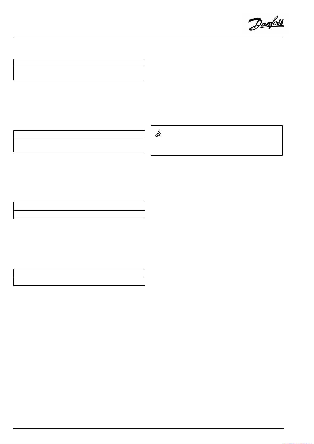
OperatingGuideECLComfort310,applicationA361
MENU>Settings>Flow/powerlimit
HighlimitY2(flow/powerlimitation,highlimit,Y-axis)
Settheflow/powerlimitationreferringtotheoutdoortemperatureset
in'LowToutX2' .
SeeAppendix“ParameterIDoverview”
ThecorrespondingXcoordinateissetin'LowToutX2' .
MENU>Settings>Flow/powerlimit
LowlimitY1(flow/powerlimitation,lowlimit,Y-axis)
Settheflow/powerlimitationreferringtotheoutdoortemperaturesetin
'HighToutX1' .
SeeAppendix“ParameterIDoverview”
ThecorrespondingXcoordinateissetin'HighToutX1' .
MENU>Settings>Flow/powerlimit
LowToutX2(flow/powerlimitation,lowlimit,X-axis)
Settheoutdoortemperaturevalueforthehighflow/powerlimitation.
1x116
1x117
Thelimitationfunctioncanoverruletheset'Temp.min'ofthedesired
flowtemperature.
1x118
SeeAppendix“ParameterIDoverview”
ThecorrespondingYcoordinateissetin'HighlimitY2'.
MENU>Settings>Flow/powerlimit
HighToutX1(flow/powerlimitation,highlimit,X-axis)
Settheoutdoortemperaturevalueforthelowflow/powerlimitation.
SeeAppendix“ParameterIDoverview”
ThecorrespondingYcoordinateissetin'LowlimitY1' .
1x119
60|©Danfoss|2021.02
AQ000086455681en-010402
Page 61
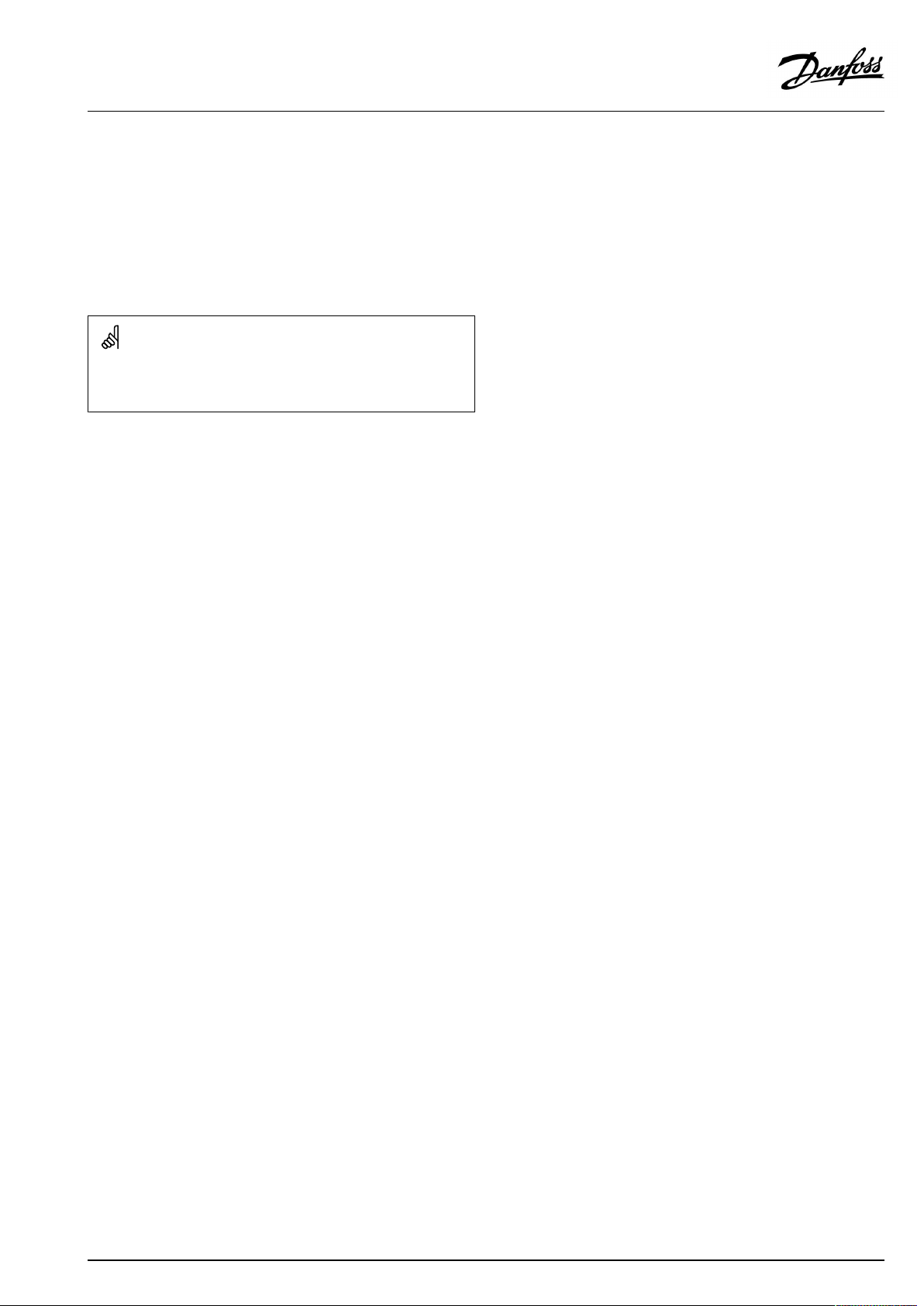
OperatingGuideECLComfort310,applicationA361
5.5Optimization
Thesection"Optimization"describesspecificapplicationrelated
issues.
Theparameters'Autosaving' ,'Boost','Optimizer','Totalstop'areall
relatedtoheatingmodeonly.
'Summer,cut-out'determine,atrisingoutdoortemperature,the
stopofheating.
ParametersindicatedwithanIDno.like"1x607"meanauniversal
parameter.
xstandsforcircuit/parametergroup.
AQ000086455681en-010402
©Danfoss|2021.02|61
Page 62
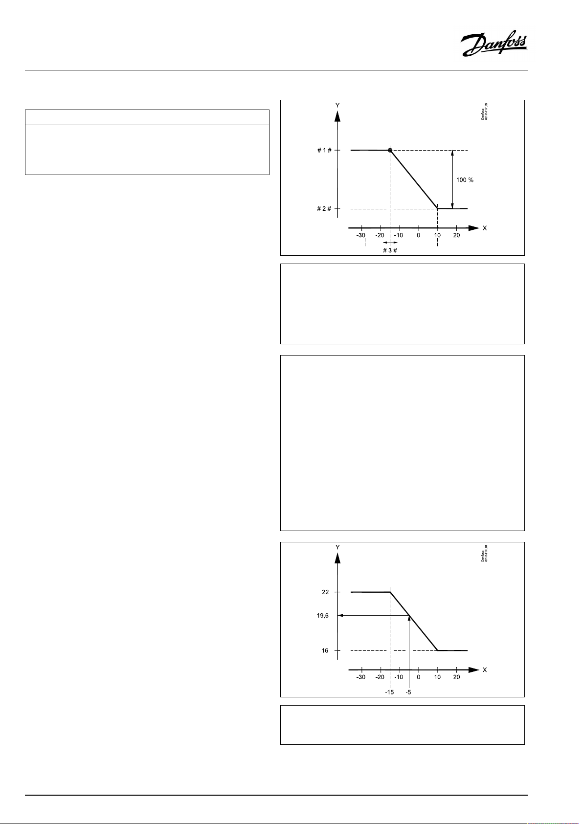
OperatingGuideECLComfort310,applicationA361
MENU>Settings>Optimization
Autosaving(savingtemp.dependentonoutdoortemp.)
Belowthesetvaluefortheoutdoortemperature,thesavingtemperature
settinghasnoinfluence.Abovethesetvaluefortheoutdoortemperature,
thesavingtemperaturerelatestotheactualoutdoortemperature.The
functionisrelevantindistrictheatinginstallationsinordertoavoidabig
changeinthedesiredflowtemperatureafterasavingperiod.
SeeAppendix“ParameterIDoverview”
OFF:
Thesavingtemperaturedoesnotdependonthe
outdoortemperature;thereductionis100%.
Value:Thesavingtemperaturedependsontheoutdoor
temperature.Whentheoutdoortemperatureisabove
10°C,thereductionis100%.Thelowertheoutdoor
temperature,thelessthetemperaturereduction.
Belowthesetvalue,thesavingtemperaturesetting
hasnoinfluence.
Comforttemperature:
Thedesiredroomtemperaturein
Comfortmode
Savingtemperature:
ThedesiredroomtemperatureinSaving
mode
ThedesiredroomtemperaturesforComfortandSavingmodes
aresetinthedisplayoverviews.
1x011
=
X
Y
#1#
#2#
#3#
Example:
Actualoutdoortemperature(T.out):
DesiredroomtemperaturesettinginComfortmode:
DesiredroomtemperaturesettinginSavingmode:
Settingin‘Autosaving’:
Outdoortemperature(°C)
=
Desiredroomtemperature(°C)
=
Desiredroomtemperature(°C),Comfortmode
=
Desiredroomtemperature(°C),Savingmode
=
Autosavingtemperature(°C),ID11011
–5°C
22°C
16°C
–15°C
Theconditionfortheoutdoortemperatureinfluence:
T.out.influence=(10-T.out)/(10-setting)=
(10-(-5))/(10-(-15))=
15/25=0,6
ThecorrecteddesiredroomtemperatureinSavingmode:
T.room.ref.Saving+(T.out.influencex(T.room.ref.ComfortT.room.ref.Saving))
16+(0,6x(22-16))=19,6°C
=
X
Y
Outdoortemperature(°C)
=
Desiredroomtemperature(°C)
62|©Danfoss|2021.02
AQ000086455681en-010402
Page 63
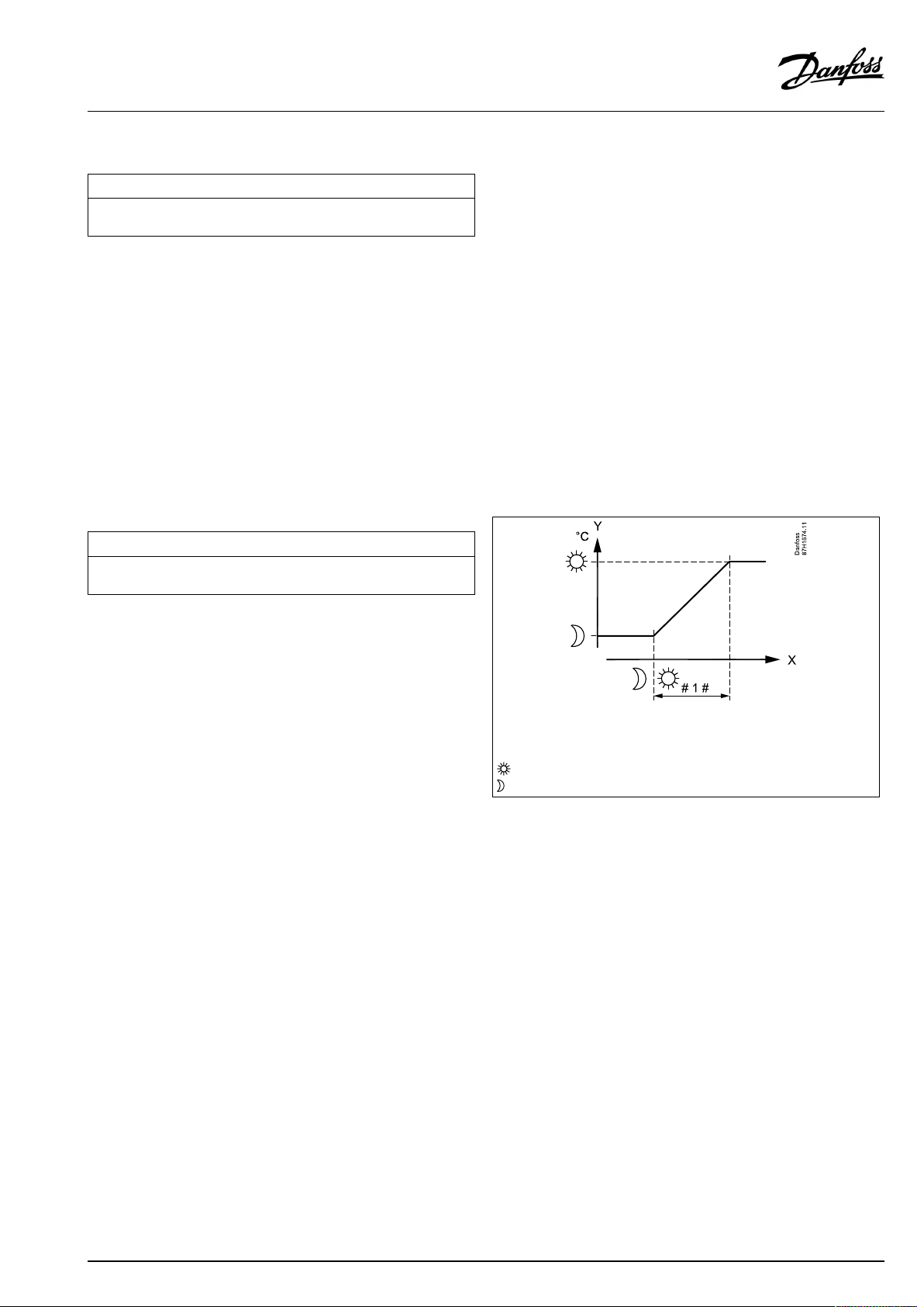
OperatingGuideECLComfort310,applicationA361
MENU>Settings>Optimization
Boost
Shortenstheheating-upperiodbyincreasingthedesiredflowtemperature
bythepercentageyouset.
SeeAppendix“ParameterIDoverview”
OFF:
Value:
Theboostfunctionisnotactive.
Thedesiredflowtemperatureisincreasedtemporarily
withthesetpercentage.
Inordertoshortentheheating-upperiodafterasaving
temperatureperiod,thedesiredflowtemperaturecanbeincreased
temporarily(max.1hour).Atoptimizingtheboostisactiveinthe
optimizationperiod('Optimizer').
IfaroomtemperaturesensororanECA30/31isconnected,the
booststopswhentheroomtemperatureisreached.
MENU>Settings>Optimization
Ramp(referenceramping)
Thetime(minutes)inwhichthedesiredflowtemperatureincreases
graduallytoavoidloadpeaksintheheatsupply.
SeeAppendix“ParameterIDoverview”
1x012
1x013
OFF:
Value:
Therampingfunctionisnotactive.
Thedesiredflowtemperatureisincreasedgraduallywith
thesetminutes.
Inordertoavoidloadpeaksinthesupplynetwork,theflow
temperaturecanbesettoincreasegraduallyafteraperiodwith
savingtemperature.Thiscausesthevalvetoopengradually.
=
X
Y
#1#
Time
=
Desiredflowtemperature
=
Rampingtime
=
Comforttemperature
=
Savingtemperature
AQ000086455681en-010402
©Danfoss|2021.02|63
Page 64

OperatingGuideECLComfort310,applicationA361
MENU>Settings>Optimization
Optimizer(optimizingtimeconstant)
Optimizesthestartandstoptimesforthecomforttemperatureperiodto
obtainthebestcomfortatthelowestenergyconsumption.
Thelowertheoutdoortemperature,theearliertheheatingcut-in.Thelower
theoutdoortemperature,thelatertheheatingcut-out.
Theoptimizedheatingcut-outtimecanbeautomaticordisabled.The
calculatedstartandstoptimesarebasedonthesettingoftheoptimizing
timeconstant.
SeeAppendix“ParameterIDoverview”
Adjusttheoptimizingtimeconstant.
Thevalueconsistsofatwodigitnumber.Thetwodigitshavethe
followingmeaning(digit1=TableI,digit2=TableII).
OFF:
Nooptimization.Theheatingstartsandstopsatthe
timessetintheschedule.
10...59:
SeetablesIandII.
TableI:
1x014
Systemtype
LeftdigitHeataccumulationofthe
building
Radiator
1-light
systems
2-medium
3-heavy
Floorheating
4-medium
systems
5-heavy
TableII:
RightdigitDimensioningtemperatureCapacity
-0-50°Clarge
-1
-45°C
-5
-25°C
normal
-9
Dimensioningtemperature:
Thelowestoutdoortemperature(usuallydeterminedbyyoursystem
designerinconnectionwiththedesignoftheheatingsystem)atwhich
theheatingsystemcanmaintainthedesignedroomtemperature.
Example
Thesystemtypeisradiator,andtheheataccumulationofthebuilding
ismedium.
Theleftdigitis2.
Thedimensioningtemperatureis-25°C,andthecapacityisnormal.
Therightdigitis5.
Result:
Thesettingistobechangedto25.
-5°C
small
64|©Danfoss|2021.02
AQ000086455681en-010402
Page 65

OperatingGuideECLComfort310,applicationA361
MENU>Settings>Optimization
Totalstop
Settingthe'Totalstop'toOFForONgivesdifferentresults,dependingonthe
actualapplication.Theconditionsare:
-Roomtemperaturecontrolledapplications
-Totalstopduringthesavingtemperatureperiod
SeeAppendix“ParameterIDoverview”
OFF:
Nototalstop.
Heatingapplicationsingeneral:
Savingmode:
Thedesiredflow/duct
temperatureisreduced
accordingtodesiredduct/
roomtemperature.
Comfortmode:Iftheroomtemperaturegets
higherthandesiredroom
temperature,theheating
switchesOFF .
Seealsotheheatingrelatedexamples.
Coolingapplications:
Savingmode:
Themotorizedcontrolvalve
closes.
ON:
Totalstop.
Heatingapplicationswithdesiredducttemperature:
Savingmode:
Thedesiredflowtemperature
issetto'Frostpr.T'(Frost
protectiontemperature).
Heatingapplicationswithdesiredroomtemperature:
Savingmode:
Theheatingisstoppedaslong
astheroomtemperatureis
higherthanthedesiredroom
temperature.
Seealsotheheatingrelatedexamples.
Coolingapplications:
Savingmode:
Themotorizedcontrolvalve
closes.
Ingeneral,whentotalstopisON,theheatingorcooling
closestotallywhenthecontrollergoesintosavingmode.
However,when'Totalstop'isON,thecontrollerhasroom
temperaturerelatedfunctionsalsoincomfortmode.
Theexamplesbelowarerelatedtoheatingapplications:
1x021
Desiredflowtemp.°C
Totalstop=ON
‘Frostpr. ’
Time
Desiredflowtemp.°C
Totalstop=OFF
‘Frostpr. ’
Time
Themin.flowtemperaturelimitation('Temp.min.')isoverruledwhen
'Totalstop'isON.
AQ000086455681en-010402
©Danfoss|2021.02|65
Page 66

OperatingGuideECLComfort310,applicationA361
MENU>Settings>Optimization
Pre-stop(optimizedstoptime)
Disabletheoptimizedstoptime.
SeeAppendix“ParameterIDoverview”
1x026
Example:OptimizationofComfortfrom07:00-22:00
OFF:
ON:
Theoptimizedstoptimeisdisabled.
Theoptimizedstoptimeisenabled.
MENU>Settings>Optimization
Summer,cut-out(limitforheatingcut-out)
1x179
SeeAppendix“ParameterIDoverview”
TheheatingcanbeswitchedOFFwhentheoutdoortemperatureis
higherthanthesetvalue.Thevalveclosesandafterthepost-run
time,theheatingcirculationpumpstops.‘Temp.min.’willbe
overruled.
TheheatingsystemswitchesONagainwhentheoutdoor
temperatureandtheaccumulated(filtered)outdoortemperature
becomelowerthanthesetlimit.
Thisfunctioncansaveenergy.
Setthevalueforoutdoortemperatureatwhichyouwantthe
heatingsystemtoswitchOFF .
X
#1#
#2#
#3#
#4#
#5#
Summer,cut-out
=
X
=
Y
=
#1#
=
#2#
=
#3#
=
#4#
=
#5#
=
Time
=
Schedule
=
Prestop=OFF
=
Prestop=ON
=
Optimizedstart
=
Optimizedstop
Time
Temperature
Actualoutdoortemperature
Cut-outtemperature(1x179)
Accummulated(filtered)outdoortemperature
Heatingenabled
Heatingdisabled
66|©Danfoss|2021.02
Theheatingcut-outisonlyactivewhenthecontrollermodeisin
scheduledoperation.Whenthecut-outvalueissettoOFF,thereis
noheatingcut-out.
AQ000086455681en-010402
Page 67

OperatingGuideECLComfort310,applicationA361
5.6Controlparameters
Controlofvalves
Themotorizedcontrolvalvesarecontrolledbymeansof3-point
controlsignal.
Valvecontrol:
Themotorizedcontrolvalveisopenedgraduallywhentheflow
temperatureislowerthanthedesiredflowtemperatureandvice
versa.
Thewaterflowthroughthecontrolvalveismanagedbymeans
ofanelectricactuator.Thecombination"actuator"and"control
valve"isalsocalledmotorizedcontrolvalve.Theactuatorcanin
thiswaygraduallyincreaseordecreasetheflowinordertochange
thesuppliedenergy.Differenttypesofactuatorsareavailable.
3-pointcontrolledactuator:
Theelectricactuatorcontainsareversiblegear-motor.Electric
"open"and"close"signalscomefromtheelectronicoutputsofthe
ECLComfortcontrollerinordertomanagethecontrolvalve.The
signalsareintheECLComfortcontrollerexpressedas"Arrow-up"
(open)and"Arrow-down"(close)anddisplayedatthevalvesymbol.
Whentheflowtemperature(forexampleatS3)islowerthanthe
desiredflowtemperature,shortopen-signalscomefromtheECL
Comfortcontrollerinordertograduallyincreasetheflow.Bythis,
theflowtemperaturewillalignwiththedesiredtemperature.
Oppositely,whentheflowtemperatureishigherthanthedesired
flowtemperature,shortclose-signalscomefromtheECLComfort
controllerinordertograduallyreducetheflow.Again,theflow
temperaturealignswiththedesiredtemperature.
Neitheropen-signalsnorclose-signalswillcomeaslongastheflow
temperaturecorrespondstothedesiredtemperature.
AQ000086455681en-010402
©Danfoss|2021.02|67
Page 68

OperatingGuideECLComfort310,applicationA361
Thermo-hydraulicactuator,ABV
Danfossthermo-actuatortypeABVisaslowactingvalveactuator.
InsidetheABVanelectricheatcoilwillheatathermostaticelement
whenanelectricsignalisapplied.Whenheatingthethermostatic
elementitexpandsinordertomanagethecontrolvalve.
Twobasictypesareavailable:ABVNC(NormalClosed)andABVNO
(normalopen).Forexample,ABVNCkeepsa2-portcontrolvalve
closedwhennoopen-signalsareapplied.
Electricopen-signalscomefromtheelectronicoutputoftheECL
Comfortcontrollerinordertomanagethecontrolvalve.When
open-signalsareappliedtotheABVNC,thevalvegraduallyopens.
Open-signalsareintheECLComfortcontrollerexpressedas
"Arrow-up"(open)anddisplayedatthevalvesymbol.
Whentheflowtemperature(forexampleatS3)islowerthanthe
desiredflowtemperature,relativelylongopen-signalscomefrom
theECLComfortcontrollerinordertoincreasetheflow.Bythis,
theflowtemperaturewillovertimebealignedwiththedesired
temperature.
Oppositely,whentheflowtemperatureishigherthanthedesired
flowtemperature,relativelyshortopen-signalscomefromtheECL
Comfortcontrollerinordertoreducetheflow.Again,theflow
temperaturealigns,overtime,withthedesiredtemperature.
ThecontroloftheDanfossthermo-actuatortypeABVusesaunique
designedalgorithmandisbasedonthePWMprinciple(Pulse
WidthModulation),wherethedurationofthepulsedetermines
themanagementofthecontrolvalve.Thepulsesarerepeated
each10sec.
Aslongastheflowtemperaturecorrespondstothedesired
temperature,thedurationoftheopen-signalswillremainconstant.
ParametersindicatedwithanIDno.like"1x607"meanauniversal
parameter.
xstandsforcircuit/parametergroup.
MENU>Settings>Controlparameters
Motorpr.(motorprotection)
Preventsthecontrollerfromunstabletemperaturecontrol(andresulting
actuatoroscillations).Thiscanoccuratverylowload.Themotorprotection
increasesthelifetimeofallinvolvedcomponents.
1x174
SeeAppendix“ParameterIDoverview”
Recommendedforductsystemswithvariableload.
OFF:
Value:
68|©Danfoss|2021.02
Motorprotectionisnotactivated.
Motorprotectionisactivatedafterthesetactivation
delayinminutes.
AQ000086455681en-010402
Page 69
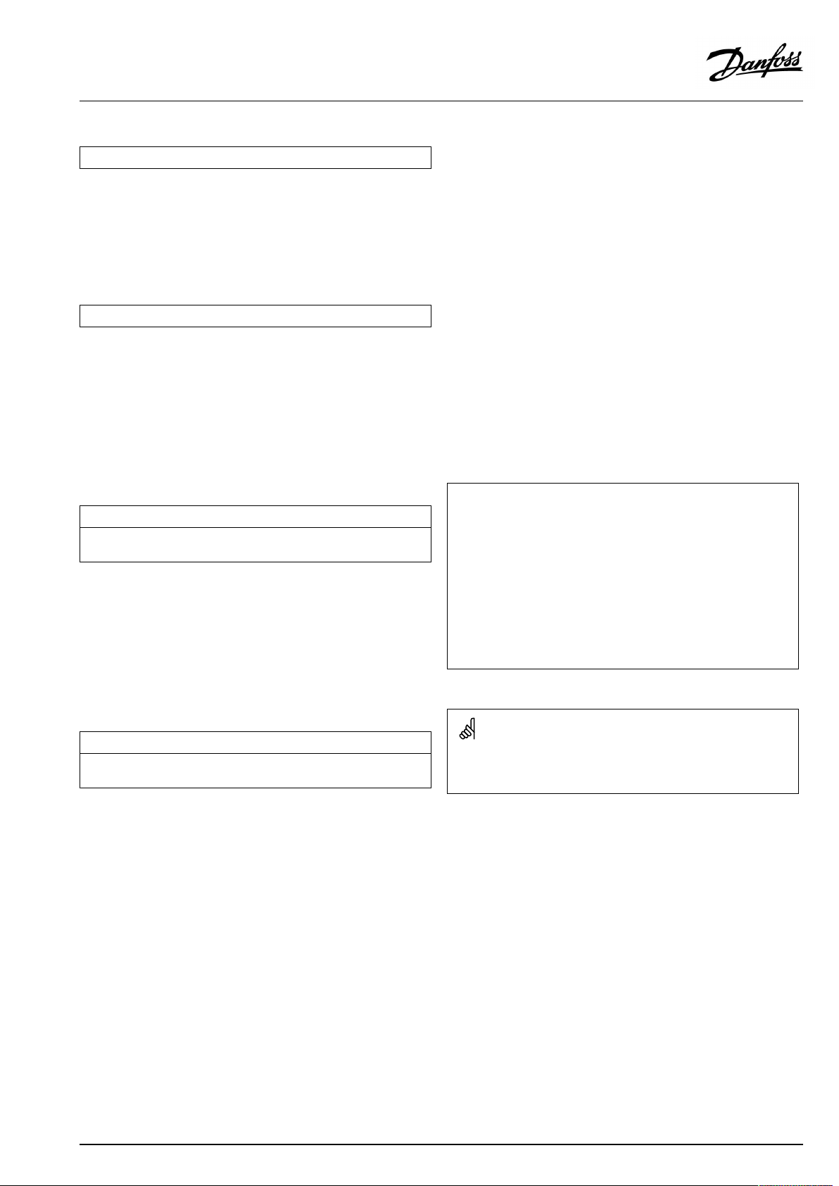
OperatingGuideECLComfort310,applicationA361
MENU>Settings>Controlparameters
Xp(proportionalband)
SeeAppendix“ParameterIDoverview”
Settheproportionalband.Ahighervaluewillresultinastablebut
slowcontroloftheflowtemperature.
MENU>Settings>Controlparameters
Tn(integrationtimeconstant)
SeeAppendix“ParameterIDoverview”
Setahighintegrationtimeconstant(inseconds)toobtainaslow
butstablereactiontodeviations.
Alowintegrationtimeconstantwillmakethecontrollerreactfast
butwithlessstability.
MENU>Settings>Controlparameters
Mrun(runningtimeofthemotorizedcontrolvalve)
‘Mrun’isthetimeinsecondsittakesthecontrolledcomponenttomove
fromfullyclosedtofullyopenposition.
SeeAppendix“ParameterIDoverview”
Setthe‘Mrun’accordingtotheexamplesormeasuretherunning
timebymeansofastopwatch.
1x184
1x185
1x186
Howtocalculatetherunningtimeofamotorizedcontrolvalve
Therunningtimeofthemotorizedcontrolvalveiscalculatedusing
thefollowingmethods:
Seatedvalves
Runningtime=
Example:
Rotatingvalves
Runningtime=
Example:90degr.x2sec./degr.=180sec.
Valvestroke(mm)xactuatorspeed(sec./mm)
5.0mmx15sec./mm=75sec.
Turningdegreesxactuatorspeed(sec./degr.)
MENU>Settings>Controlparameters
Nz(neutralzone)
Whentheactualflowtemperatureiswithintheneutralzone,thecontroller
doesnotactivatethemotorizedcontrolvalve.
SeeAppendix“ParameterIDoverview”
Settheacceptableflowtemperaturedeviation.
Settheneutralzonetoahighvalueifyoucanacceptahigh
variationinflowtemperature.
1x187
Theneutralzoneissymmetricalaroundthedesiredflowtemperature
value,i.e.halfthevalueisaboveandhalfthevalueisbelowthis
temperature.
AQ000086455681en-010402
©Danfoss|2021.02|69
Page 70

OperatingGuideECLComfort310,applicationA361
IfyouwanttotunethePIregulationprecisely,youcanusethefollowingmethod:
•Setthe‘Tn’(integrationtimeconstant)toitsmax.value(999sec.).
•Decreasethevalueforthe‘Xp’(proportionalband)untilthesystemstartshunting(i.e.getsunstable)withaconstantamplitude(it
mightbenecessarytoforcethesystembysettinganextremelowvalue).
•Findthecriticaltimeperiodonthetemperaturerecorderoruseastopwatch.
Temp.
Thiscriticaltimeperiodwillbecharacteristicforthesystem,andyoucanevaluatethesettingsfromthiscriticalperiod.
‘Tn’=
0.85xcriticaltimeperiod
‘Xp’=
2.2xproportionalbandvalueinthecriticaltimeperiod
Iftheregulationseemstobetooslow,youcandecreasetheproportionalbandvalueby10%.Makesurethereisaconsumption
whenyousettheparameters.
Criticaltimeperiod
Time
70|©Danfoss|2021.02
AQ000086455681en-010402
Page 71

OperatingGuideECLComfort310,applicationA361
5.7Pumpcontrol
Thisapplicationcanoperatewithoneortwocirculationpumps.
Whenoperatingwithtwocirculationpumps,thepumpsare
controlledalternately,accordingtoatimeset-up.Whenapumpis
switchedONthecontrolleriswaitingfordifferentialpressure(S7
forheatingcircuit,S8forDHWcircuit)tobuildup.Ifdifferential
pressureisnotachieved,analarmisgeneratedandtheECL
ComfortcontrollerswitchesONtheotherpump.
Ifnoneofthepumpscancomeintooperation(detectedbymeans
ofthedifferentialpressureswitch),thealarmisactivatedandthe
motorizedcontrolvalvecloses(asafetyfunction).
ParametersindicatedwithanIDno.like"1x607"meanauniversal
parameter.
xstandsforcircuit/parametergroup.
MENU>Settings>Pumpcontrol
Pexercise(pumpexercise)
Exercisesthepumptoavoidblockinginperiodswithoutheatdemand.
SeeAppendix“ParameterIDoverview”
OFF:
ON:
Thepumpexerciseisnotactive.
ThepumpisswitchedONfor1minuteeverythirddayat
noon(12:14hours).
MENU>Settings>Pumpcontrol
Retrytime
Ifanalarmhasbeengeneratedforthepumporalarmshavebeengenerated
forbothpumps,thissettingwilldeterminethetimebetweenthetimeofthe
alarmandtheretrytimeforrepeatedpumpstart.
SeeAppendix“ParameterIDoverview”
OFF:
Noretrytimerequiredafteranalarm.Thepumpor
pumpsinquestionwillnotberestarted.
1...99:
Afteranalarm,thepumporpumpswillberestarted
afterthesettime.
1x022
1x310
AQ000086455681en-010402
©Danfoss|2021.02|71
Page 72

OperatingGuideECLComfort310,applicationA361
MENU>Settings>Pumpcontrol
Change,duration
Thenumberofdaysbetweenshiftofcirculationpumps.Theshifttakesplace
atthetimesetin'Changetime' .
SeeAppendix“ParameterIDoverview”
MENU>Settings>Pumpcontrol
Changetime(changeovertime)
Theexacttimeoftheday,wheretheshiftmusttakeplace.Thedayisdivided
into24hours.Thefactorysettinghereis12whichmeans12:00(noon).
1x311
=
X
#1#
#2#
#3#
1x312
Time
=
PumpP3
=
PumpP5
=
Change,duration(days)
SeeAppendix“ParameterIDoverview”
MENU>Settings>Pumpcontrol
Stab.time(stabilizationtime)
Settingofmax.timetoelapsebetweenpumpstartcommandandfeedback
fromdifferentialpressureswitch.
Ifthedifferentialpressureswitchdoesnotgivefeedbackwithinthesettime,
thealarmwillbeactivatedandtheotherpumpwillgetastartcommand.
SeeAppendix“ParameterIDoverview”
=
X
#1#
#2#
#3#
1x313
Time
=
PumpP3
=
PumpP5
=
Changetime(clocktime)
Ifthechosenstabilizationtime(‘Stab.time’)istooshort,theactive
pumpwillstopimmediatelyafterthestabilizationtimehaselapsed.
72|©Danfoss|2021.02
AQ000086455681en-010402
Page 73

OperatingGuideECLComfort310,applicationA361
MENU>Settings>Pumpcontrol
Chan.-overtime(change-overtime)
Settingoftimetoelapsebetweenthepumpstopcommandforonepump
andthestartcommandfortheotherpump.
Thechange-overtimecanensurethatapumpisstoppedefficientlybefore
theotherpumpstarts.
SeeAppendix“ParameterIDoverview”
OFF:
1...99:
Onecirculationpumpintheapplication.
Timeforchange-over.
1x314
=
X
#1#
#2#
#3#
Time
=
PumpP3
=
PumpP5
=
Change-overtime(sec.)
‘Chan.-overtime’hastobechoseninsystemswithtwopumps.
Thestatusofthedifferentialpressureswitchisshownin'Input
overview'.
(Navigation:MENU>Commoncontroller>Inputoverview).
Example:
S7status...OFF/ON
OFF:
Thedifferentialpressureswitchisclosed(differential
pressureisOK)
ON:
Thedifferentialpressureswitchisopen(differential
pressureisnotOK)
AQ000086455681en-010402
©Danfoss|2021.02|73
Page 74

OperatingGuideECLComfort310,applicationA361
5.8Refillwater
Leaksontheconsumerssidewillresultinfallingstaticpressureand
therebyapoorsupplyofheating.Arefillwaterfunctioncaninject
watertoincreasethestaticpressure.
Thisapplicationcanmonitorthestaticpressureandenablethe
refillwaterfunctionwhenthepressureistoolow.
Thepressureismeasuredbymeansofapressuretransmitter
(givinga0-10voltsignalinrelationtothemeasuredpressure)or
apressureswitch.
Whenapressuretransmittersignalisused,twosettingsinthe
controllerrepresentpressuresetpointanddifference.
Whenapressureswitchsignalisused,thesetpointand(maybe)
theswitchingdifferenceissetonthepressureswitch.
Whenatoolowpressureisdetectedtherefillwaterpumpis
switchedONand,afterasettime,theON-OFFvalveisactivated.
Ifthepressureisnotachievedwithinasettime,analarmis
generated.TheECLComfortcontrollerswitchesOFFthecirculation
pumpsafter60secondsandthecontrolvalvecloses(asafety
function).
MENU>Settings>Refillwater
Pressure
CircuitSettingrange
1
Read-outonly
Factorysetting
Theread-outcanbeavalue(inbar):
•Thepressureismeasuredbymeansofapressuretransmitter.
Thetransmittersendsthemeasuredpressureasa0-10Vora
4-20mAsignal.Thevoltagesignalcanbeapplieddirectlyto
inputS10.Acurrentsignalisconvertedbymeansofaresistor
toavoltageandthenappliedtoinputS10.Themeasured
voltageoninputS10mustbeconvertedtoapressurevalueby
thecontroller.Thisproceduresetsupthescaling.
Pushthedialtoseethegraphandenterthevaluesetsforthe
inputvoltage(2and10volt)anddisplayedpressure(inbar).
Pressurevaluerange:0.0...30.0bar
Fixedvoltagesettings:2Vand10V
Factorysettings:(2.0,0)and(10,20.0)
Thismeansthatthe‘Pressure'is0.0barat2Vand20.0barat
10V.
Typically,thehigherthevoltage,thehigherthedisplayed
pressure.
Ortheread-outcanbeOFForON:
•Thepressureismeasuredbymeansofapressureswitch.The
pressureswitchhasanopencontactwhenmeasuringatoolow
pressure(shownasOFF).WhenmeasuredpressureisOK,the
contactisclosed(shownasON).
Thepressureswitchcontact(potentialfree)isconnected
directlytoinputS10.
=
X
Y
#1#
#2#
Volt
=
Bar
=
0bar
=
30,0bar
Thisscalingmenuisalwaysshown,regardlesswhetherapressure
transmitterorapressureswitchisused.
74|©Danfoss|2021.02
AQ000086455681en-010402
Page 75

OperatingGuideECLComfort310,applicationA361
ParametersindicatedwithanIDno.like"1x607"meanauniversal
parameter.
xstandsforcircuit/parametergroup.
MENU>Settings>Refillwater
Pexercise(pumpexercise)
Thetimethepumpisactivatedduringexercise.Exercisetakesplaceevery
day(at12:00).
SeeAppendix“ParameterIDoverview”
OFF:
1...200:
Nopumpexercise.
Activationtimeduringexercise.
MENU>Settings>Refillwater
Pressure,des.(desiredpressure)
Readoutofthecalculateddesiredpressureattheinlet/outlet.
Accesstoconversion(scale)settings:Pushdial.
SeeAppendix“ParameterIDoverview”
Settherelationshipbetweenoutdoortemperatureanddesired
pressure.
1x320
MENU>Settings>Refillwater
Pressure,diff.(switchingdifference)
Settingoftheswitchingdifferenceformeasuredstaticpressure(pressure
transmitter).Thedifferenceissymmetricalaroundthe'Pressuredes. 'See
also'Pressuredes. '
SeeAppendix“ParameterIDoverview”
AQ000086455681en-010402
=
X
Y
1x322
Thesettingsin'Pressure,des. 'and'Pressure,diff.'havenoinfluence
whenapressureswitchisused.
Outdoortemperature
=
Desiredpressure(Pascal)
©Danfoss|2021.02|75
Page 76

OperatingGuideECLComfort310,applicationA361
MENU>Settings>Refillwater
Time-out
Settingofthemax.timeforrefill.Thepressure,measuredbyS10,mustbe
OKwithinthesettime.Ifnot,therefillwaterfunctionstopsandanalarm
isactivated.
SeeAppendix“ParameterIDoverview”
1x323
=
X
#1#
#2#
#3#
Time
=
PressureOK/notOK
=
Refillpump
=
Time-out
76|©Danfoss|2021.02
=
X
#1#
#2#
#3#
#4#
Time
=
PressureOK/notOK
=
Refillpump
=
Time-out
=
Alarm
AQ000086455681en-010402
Page 77
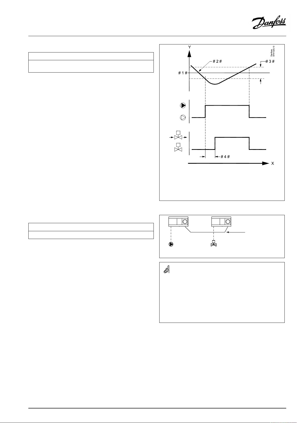
OperatingGuideECLComfort310,applicationA361
MENU>Settings>Refillwater
Valvedelay
SettingofthetimeforactivationoftheON/OFFvalveafterstartoftherefill
waterpump.
SeeAppendix“ParameterIDoverview”
1x325
=
X
Y
#1#
#2#
#3#
#4#
Time
=
Pressure
=
Pressuredesired
=
Actualpressure
=
Pressuredifference
=
Valvedelay
MENU>Settings>Refillwater
No.ofpumps
Settingofthenumberofpumpsintherefillwatercircuit.
SeeAppendix“ParameterIDoverview”
OFF:
Therefillwaterpumpfunctioniscontrolledbythe
mastercontroller.
1...2:
Therefillwaterfunctionhasoneortwopumps.
1x326
Refillwater
pump
WhenselectingOFFandademandforrefilloccurs,thecontroller
fortheactualcircuitsendstherequirementviatheECL485
communicationbustothemastercontroller.
Themastermustberunninganapplicationwithrefillwaterfunction.
Themasterstartstherefillwaterpumpandsends,viatheECL485
communicationbus,amessagethattherefillwaterpumpisstarted.
Therefillwatervalvethenopens.
Theslavemusthaveanaddress1...9.
Refillwater
valve
ECL485
communication
bus
AQ000086455681en-010402
©Danfoss|2021.02|77
Page 78

OperatingGuideECLComfort310,applicationA361
MENU>Settings>Refillwater
Inputtype
Choiceofpressureinputsignal.
SeeAppendix“ParameterIDoverview”
OFF:
Pressuresignalisnotrequired.Therefillwaterfunction
isdisabled.
AI:
DI:
Theinputsignalisananalogsignal(0-10V).
Theinputsignalisadigitalsignal(switchOFForON).
1x327
Whenselecting‘OFF’ ,therefillwatersystemcouldbeself-acting.
Thestaticpressureisshownin'Inputoverview'asavalueinbaror
OFF/ON.
Example:
OFF:
Thepressureswitchisopen(pressureisnotOK)
ON:
Thepressureswitchisclosed(pressureisOK)
78|©Danfoss|2021.02
AQ000086455681en-010402
Page 79
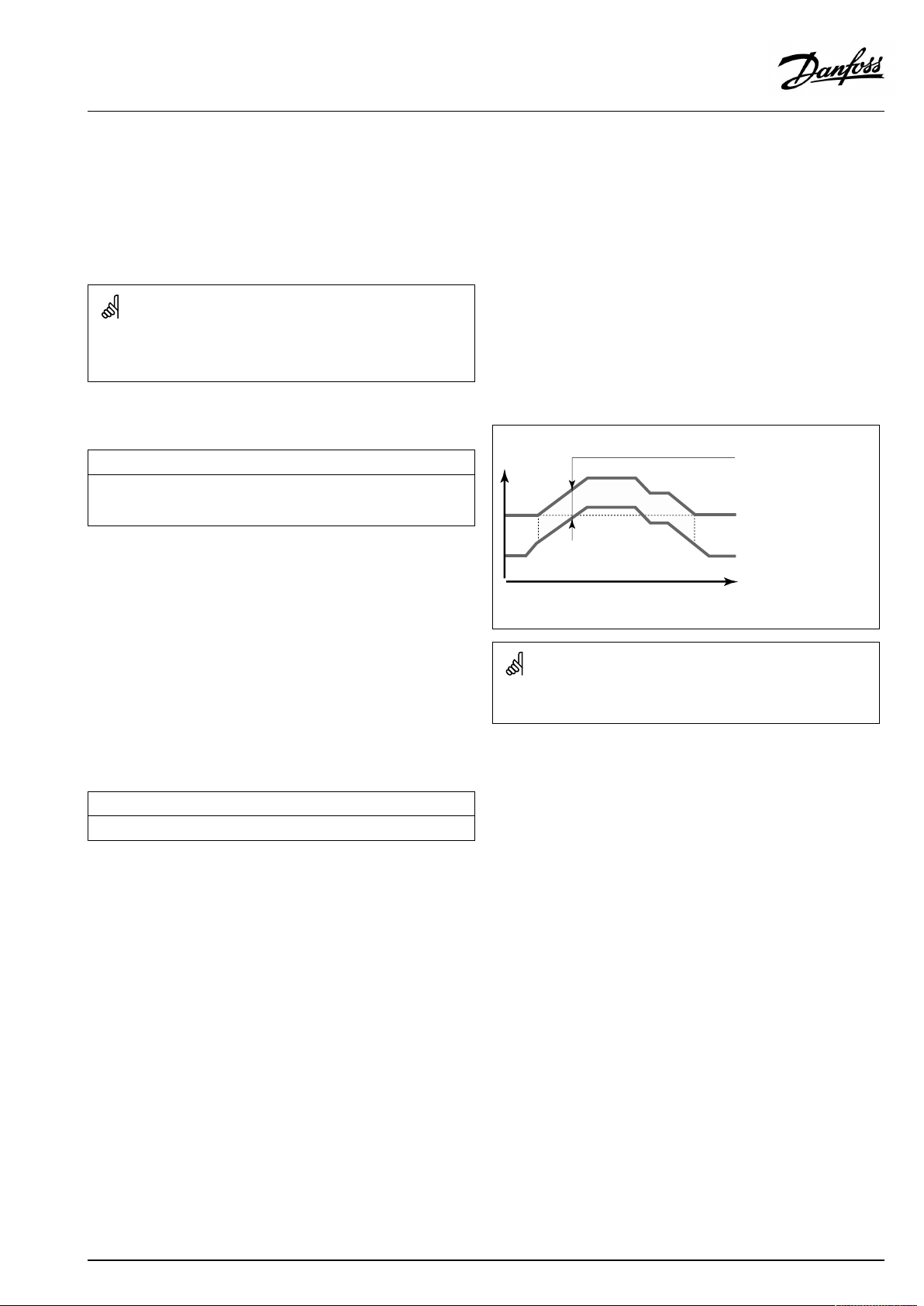
OperatingGuideECLComfort310,applicationA361
5.9Application
Thesection"Application"describesspecificapplicationrelated
issues.
Someoftheparameterdescriptionsareuniversalfordifferent
applicationkeys.
ParametersindicatedwithanIDno.like"1x607"meanauniversal
parameter.
xstandsforcircuit/parametergroup.
MENU>Settings>Application
Demandoffset
Thedesiredflowtemperatureinheatingcircuit1canbeinfluencedbythe
demandforadesiredflowtemperaturefromanothercontroller(slave)or
anothercircuit.
SeeAppendix“ParameterIDoverview”
OFF:
Thedesiredflowtemperatureincircuit1isnot
influencedbythedemandofanyothercontroller(slave
orcircuit2).
Value:
Thedesiredflowtemperatureisincreasedbytheset
valuein‘Demandoffset’ ,ifthedemandoftheslave/
circuit2ishigher.
MENU>Settings>Application
Mexercise(valveexercise)
Exercisesthevalvetoavoidblockinginperiodswithoutheatdemand.
SeeAppendix“ParameterIDoverview”
Temp.
1x017
Thefunctionof‘Demandoffset’cancompensateforheatlosses
betweenmasterandslavecontrolledsystems.
1x023
Settingin
‘Demandoffset’
Des.flowtemp.,
circuit1
Des.flowtemp.,
circuit2
Time
OFF:
ON:
AQ000086455681en-010402
Thevalveexerciseisnotactive.
Thevalveopensfor7minutesandclosesfor7minutes
everythirddayatnoon(12:00hours).
©Danfoss|2021.02|79
Page 80

OperatingGuideECLComfort310,applicationA361
MENU>Settings>Application
DHWpriority(closedvalve/normaloperation)
Theheatingcircuitcanbeclosedwhenthecontrolleractsasslaveandwhen
DHWheating/chargingisactiveinthemaster.
SeeAppendix“ParameterIDoverview”
OFF:
Theflowtemperaturecontrolremainsunchanged
duringactiveDHWheating/charginginthemaster
controller.
ON:
Thevalveintheheatingcircuitisclosed*duringactive
DHWheating/charginginthemastercontroller.
*Thedesiredflowtemperatureissettothevaluesetin
‘Frostpr.T’
MENU>Settings>Application
PfrostT(circulationpump,frostprotectiontemp.)
Frostprotection,basedontheoutdoortemperature.
Whentheoutdoortemperaturegetsbelowthesettemperaturevaluein‘P
frostT’ ,thecontrollerautomaticallyswitchesONthecirculationpump(for
exampleP1orX3)toprotectthesystem.
SeeAppendix“ParameterIDoverview”
OFF:
Value:
Nofrostprotection.
CirculationpumpisONwhentheoutdoortemperature
isbelowthesetvalue.
1x052
Thissettingmustbeconsideredifthiscontrollerisaslave.
1x077
Undernormalconditions,yoursystemisnotfrostprotectedifyour
settingisbelow0°CorOFF.
Forwater-basedsystems,asettingof2°Cisrecommended.
Iftheoutdoortemperaturesensorisnotconnectedandthefactory
settinghasnotbeenchangedto'OFF' ,thecirculationpumpisalways
ON.
MENU>Settings>Application
PheatT(heatdemand)
Whenthedesiredflowtemperatureisabovethesettemperaturein‘PheatT’ ,
thecontrollerautomaticallyswitchesONthecirculationpump.
1x078
SeeAppendix“ParameterIDoverview”
Value:
ThecirculationpumpisswitchedONwhenthedesired
flowtemperatureisabovethesetvalue.
MENU>Settings>Application
Frostpr .T(frostprotectiontemp.)
SetthedesiredflowtemperatureattemperaturesensorS3toprotectthe
systemagainstfrost(atheatingcut-out,totalstopetc.).
WhenthetemperatureatS3getslowerthanthesetting,themotorized
controlvalveopensgradually.
1x093
SeeAppendix“ParameterIDoverview”
Thevalveisfullyclosedaslongasthepumpisnotswitchedon.
Thefrostprotectiontemperaturecanalsobesetinyourfavorite
displaywhenthemodeselectorisinfrostprotectionmode.
80|©Danfoss|2021.02
AQ000086455681en-010402
Page 81

OperatingGuideECLComfort310,applicationA361
Overridemodefunctions:
ThefollowingsettingsdescribethefunctioningeneralfortheECL
Comfort210/296/310series.Theexplainedmodesaretypical
andnotapplicationrelated.Theymightdifferfromtheoverride
modesinyourapplication.
MENU>Settings>Application
Ext.input(externaloverride)
Choosetheinputfor'Ext.input'(externaloverride).Bymeansofaswitch
thecontrollercanbeoverriddento‘Comfort’,'Saving' ,'Frostprotection'or
'Constanttemperature'mode.
1x141
SeeAppendix“ParameterIDoverview”
OFF:
S1...S16:
Noinputshavebeenselectedforexternaloverride.
Inputselectedforexternaloverride.
IfS1...S6ischosenasoverrideinput,theoverrideswitchmusthave
gold-platedcontacts.
IfS7...S16ischosenasoverrideinput,theoverrideswitchcanbea
standardcontact.
Seethedrawingsforconnectionexamplesofoverrideswitchand
overriderelaytoinputS8.
S7...S16arerecommendedforoverrideswitch.
Example:Connectionofanoverrideswitch
Example:Connectionofanoverriderelay
IfECA32ismounted,alsoS11...S16canbeused.
IfECA35ismounted,alsoS11orS12canbeused.
Chooseonlyanunusedinputforoverride.Ifanalreadyusedinputis
appliedforoverride,thefunctionalityofthisinputisalsoneglected.
Seealso‘Ext.mode’.
AQ000086455681en-010402
©Danfoss|2021.02|81
Page 82

OperatingGuideECLComfort310,applicationA361
MENU>Settings>Application
Ext.mode(externaloverridemode)
ThemodeoverridecanbeactivatedforSaving,Comfort,Frostpr.or
ConstantTmode.
Foroverride,thecontrollermodemustbeinscheduledmode.
SeeAppendix“ParameterIDoverview”
Chooseanoverridemode:
SAVING:
Thecircuitinquestionisinsavingmodewhenthe
overrideswitchisclosed.
COMFORT:
Thecircuitinquestionisincomfortmodewhenthe
overrideswitchisclosed.
FROSTPR.:
TheheatingorDHWcircuitcloses,butisstillfrost
protected.
CONSTANTT:
Thecircuitinquestioncontrolsaconstant
temperature*)
*)
Seealso'DesiredT'(1x004),settingofdesiredflow
temperature(MENU>Settings>Flowtemperature)
Seealso'Con.T,ret.Tlim. '(1x028),settingofreturn
temperaturelimitation(MENU>Settings>Return
limit)
Theprocessdiagramsshowthefunctionality.
1x142
Seealso‘Ext.input’.
Example:OverridetoComfortmode
#1#=Overrideswitch(notactivated/activated)
#2#=Functionmode(Schedule/Comfort)
#3#=Time
Example:OverridetoSavingmode
#1#=Overrideswitch(notactivated/activated)
#2#=Functionmode(Schedule/Saving)
#3#=Time
Theresultofoverrideto'Saving'modedependsonthesettingin
'Totalstop'.
Totalstop=OFF:Heatingreduced
Totalstop=ON:Heatingstopped
82|©Danfoss|2021.02
AQ000086455681en-010402
Page 83
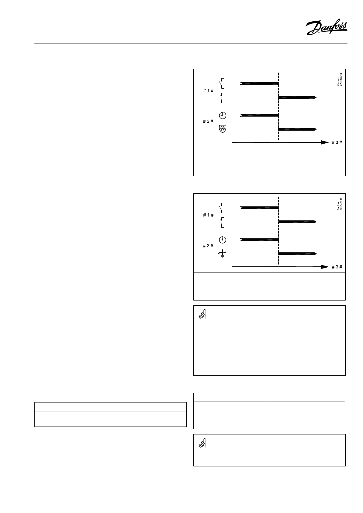
OperatingGuideECLComfort310,applicationA361
Example:OverridetoFrostprotectionmode
#1#=Overrideswitch(notactivated/activated)
#2#=Functionmode(Schedule/Frostpr.)
#3#=Time
Example:OverridetoConstanttemperaturemode
MENU>Settings>Application
Min.act.time(min.activationtimegearmotor)
Themin.pulseperiodof20ms(milliseconds)foractivationofthegear
motor.
SeeAppendix“ParameterIDoverview”
#1#=Overrideswitch(notactivated/activated)
#2#=Functionmode(Schedule/Const.T)
#3#=Time
The"Const.T"valuecanbeinfluencedby:
•temp.max.
•temp.min.
•roomtemp.limit
•returntemp.limit
•flow/powerlimit
SettingexampleValuex20ms
1x189
240ms
10200ms
501000ms
Thesettingshouldbekeptashighasacceptabletoincreasethe
lifetimeoftheactuator(gearmotor).
AQ000086455681en-010402
©Danfoss|2021.02|83
Page 84

OperatingGuideECLComfort310,applicationA361
5.10Alarm
Thesection"Alarm"describesspecificapplicationrelatedissues.
ApplicationA231offerstwotypesofalarms:
Type:
1
1
2
2
Thealarmfunctionsactivatethealarmbellsymbol.
ThealarmfunctionsactivateA1(Relay4).
Thealarmrelaycanactivatealamp,ahorn,aninputtoanalarm
transmittingdeviceetc.
Thealarmsymbol/relayisactivated:
•(type1)aslongasthealarmreasonispresent(automaticreset).
•(type2)evenifthealarmreasondisappearsagain(manual
reset).
Alarmtype1:
•Iftheflowtemperaturedeviatesmorethanthesetdifferences
fromthedesiredflowtemperature,thealarmsymbol/relay
willbeactivated.
Iftheflowtemperaturebecomesacceptable,thealarmsymbol/
relaywillbede-activated.
Description:
Actualflowtemperaturediffersfromthedesired
flowtemperature
A331.1,A331.2:
TheuniversalalarminputS9isactivated
Anactivatedcirculationpumpdoesnotgenerate
apressuredifference
Therefillwaterfunctiondoesnotgeneratea
pressurewithinsettime
•IftheuniversalalarminputS9isactivated.
IftheuniversalalarminputS9isde-activated,thealarmsymbol/
relaywillbede-activated.
Alarmtype2:
•IfpumpdifferentialpressureS7isnotregistered,thealarm
symbol/relaywillbeactivated.Furthermore,thecontrolvalve
willclose.
Thisalarmmustbemanuallyreset.
•IfRefillwaterfunctionhasnotgeneratedacceptablepressure,
thealarmsymbol/relaywillbeactivated.
Thisalarmmustbemanuallyreset.
ParametersindicatedwithanIDno.like"1x607"meanauniversal
parameter.
xstandsforcircuit/parametergroup.
84|©Danfoss|2021.02
AQ000086455681en-010402
Page 85

OperatingGuideECLComfort310,applicationA361
5.10.1Temp.monitor.
MENU>Settings>Alarm
Upperdifference
Thealarmisactivatediftheactualflowtemperatureincreasesmorethan
thesetdifference(acceptabletemperaturedifferenceabovethedesired
flowtemperature).Seealso'Delay' .
SeeAppendix“ParameterIDoverview”
1x147
Upperdifference
OFF:
Value:
Therelatedalarmfunctionisnotactive.
Thealarmfunctionisactiveiftheactualtemperature
getsabovetheacceptabledifference.
MENU>Settings>Alarm
Lowerdifference
Thealarmisactivatediftheactualflowtemperaturedecreasesmorethan
thesetdifference(acceptabletemperaturedifferencebelowthedesired
flowtemperature).Seealso'Delay' .
SeeAppendix“ParameterIDoverview”
OFF:
Value:
Therelatedalarmfunctionisnotactive.
Thealarmfunctionisactiveiftheactualtemperature
getsbelowtheacceptabledifference.
=
X
Y
#1#
#2#
1x148
Time
=
Temperature
=
Upperdifference
=
Desiredflowtemperature
Lowerdifference
=
X
Y
#1#
#2#
AQ000086455681en-010402
Time
=
Temperature
=
Lowerdifference
=
Desiredflowtemperature
©Danfoss|2021.02|85
Page 86

OperatingGuideECLComfort310,applicationA361
MENU>Settings>Alarm
Delay,example
Ifanalarmconditionfromeither'Upperdifference'or'Lowerdifference'is
presentforalongertimethanthesetdelay(inminutes),thealarmfunction
isactivated.
SeeAppendix“ParameterIDoverview”
1x149
Delay,example
Value:
Thealarmfunctionwillbeactivatedifthealarm
conditionremainsafterthesetdelay.
MENU>Settings>Alarm
Lowesttemp.
Thealarmfunctionwillnotbeactivatedifthedesiredflowtemperature
islowerthanthesetvalue.
SeeAppendix“ParameterIDoverview”
5.10.2Clearalarm
=
X
Y
#1#
#2#
#3#
#4#
1x150
Ifthecauseofthealarmdisappears,thealarmindicationandoutput
alsodisappear.
Time
=
Temperature
=
Lowerdifference
=
Desiredflowtemperature
=
Actualflowtemperature
=
Delay(ID1x149)
Clearalarm
Ifanalarmhasbeengenerated,abellisshowninoneof
thefavoritedisplay(see‘Monitoringtemperaturesandsystem
components’)orinanoverviewdisplay(see‘Understandingthe
controllerdisplay’).Thefollowingmenusareusedtolocatethe
alarmcauseandreset(clear)thealarmsignal.Evenwhenthecause
ofthealarmhasdisappeared,theindicationwillstillbeactiveuntil
theclearalarmprocedurehasbeencarriedout.
MENU>Settings>Alarm
Circ.pumps
Choosewhetherthealarmshouldbeclearedornot.
1x315
SeeAppendix“ParameterIDoverview”
OFF:
ON:
Thealarmhasnotbeenactivated.
Thealarmhasbeenactivated.
Clearalarmprocedure:
Ifthestatusis‘ON’:Change‘ON’to‘OFF’ .
Ifthestatusis‘OFF’:Itisnotpossibletochangeitto‘ON’ .
86|©Danfoss|2021.02
AQ000086455681en-010402
Page 87

OperatingGuideECLComfort310,applicationA361
MENU>Settings>Alarm
Refillwater
Choosewhetherthealarmshouldbeclearedornot.
SeeAppendix“ParameterIDoverview”
OFF:
ON:
Thealarmhasnotbeenactivated.
Thealarmhasbeenactivated.
Clearalarmprocedure:
Ifthestatusis‘ON’:Change‘ON’to‘OFF’ .
Ifthestatusis‘OFF’:Itisnotpossibletochangeitto‘ON’ .
1x324
AQ000086455681en-010402
©Danfoss|2021.02|87
Page 88

OperatingGuideECLComfort310,applicationA361
5.11Alarmoverview
MENU>Alarm>Alarmoverview
Thismenushowsthealarmtypes,forexample:
•"2:T emp.monitor"
•"32:Tsensordefect"
Thealarmhasbeenactivatedifthealarmsymbol(abell)(
presenttotherightofthealarmtype.
Resettinganalarm,ingeneral:
)is
MENU>Alarm>Alarmoverview:
Lookforalarmsymbolinspecificline.
(Example:"2:Temp.monitor")
Movecursortothelineinquestion.
Pushdial.
Alarmoverview:
Alarmsourcesarelistedinthisoverviewmenu.
Someexamples:
"2:Temp.monitor"
"5:Pump1"
"10:DigitalS12"
"32:Tsensordefect"
Thealarmoverviewliststhecomponentsorfunctionsthatcould
causeanalarm.
Thenumbertotheleft(i.e.1,5,6,7)relatestothealarmnumber
whichissentbyModbuscommunicationtoaSCADAsystem.
Twoalarmtypescanbepresent,ie.thealarmsthatareloggedand
thealarmsthatarenotlogged.
Example:
Thealarmtypefor‘Refillwater’ ,‘Pump3’and‘Pump5’arelogged
alarms.Thismeansthatthealarmsymbolwillremainuntil
thealarmhasbeenclearedevenifthecauseofthealarmhas
disappeared.
Thealarmtypefor‘Temp.monitor’e.g.isnotaloggedalarmwhich
meansthatthealarmsymbolwillonlybepresentaslongasthe
alarmcauseexists.
Relatedtotheexamples,thenumbers2,5and10areusedinthealarm
communicationtotheBMS/SCADAsystem.
Relatedtotheexamples,"Temp.monitor" ,"Pump1"and"DigitalS12"
arethealarmpoints.
Relatedtotheexamples,"32:Tsensordefect"indicatesthemonitoring
ofconnectedsensors.
Alarmnumbersandalarmpointsmightdifferdependingonactual
application.
Example:
’PumpP5’has
causedanalarm.
Thealarmoverviewwillonlylistcomponentsorfunctionsthatcould
causeanalarm.
88|©Danfoss|2021.02
AQ000086455681en-010402
Page 89
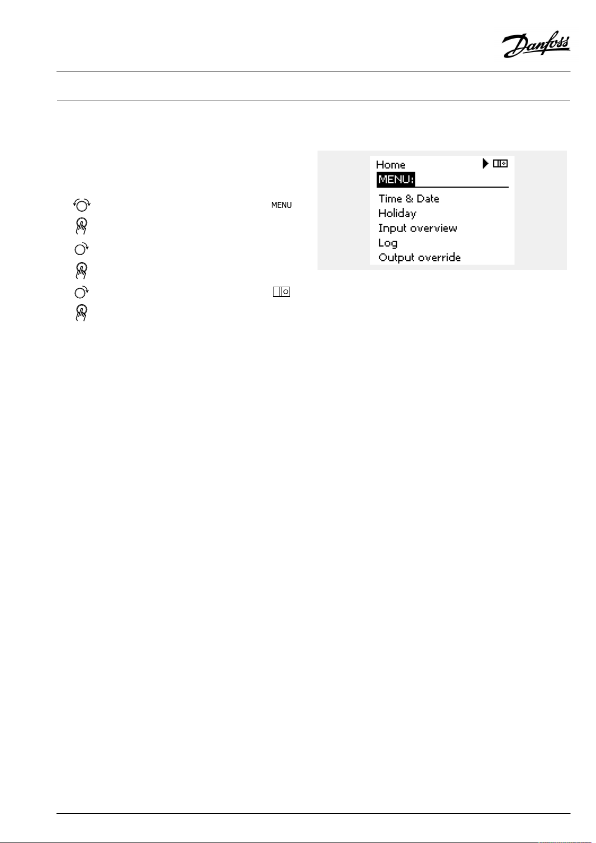
OperatingGuideECLComfort310,applicationA361
6.0Commoncontrollersettings
6.1Introductionto‘Commoncontrollersettings’
Somegeneralsettingswhichapplytotheentirecontrollerare
locatedinaspecificpartofthecontroller.
Toenter‘Commoncontrollersettings’:
Action:Purpose:
Choose‘MENU’inanycircuit
Confirm
Choosethecircuitselectoratthetop
rightcornerinthedisplay
Confirm
Choose‘Commoncontrollersettings’
Confirm
Examples:
Circuitselector
AQ000086455681en-010402
©Danfoss|2021.02|89
Page 90
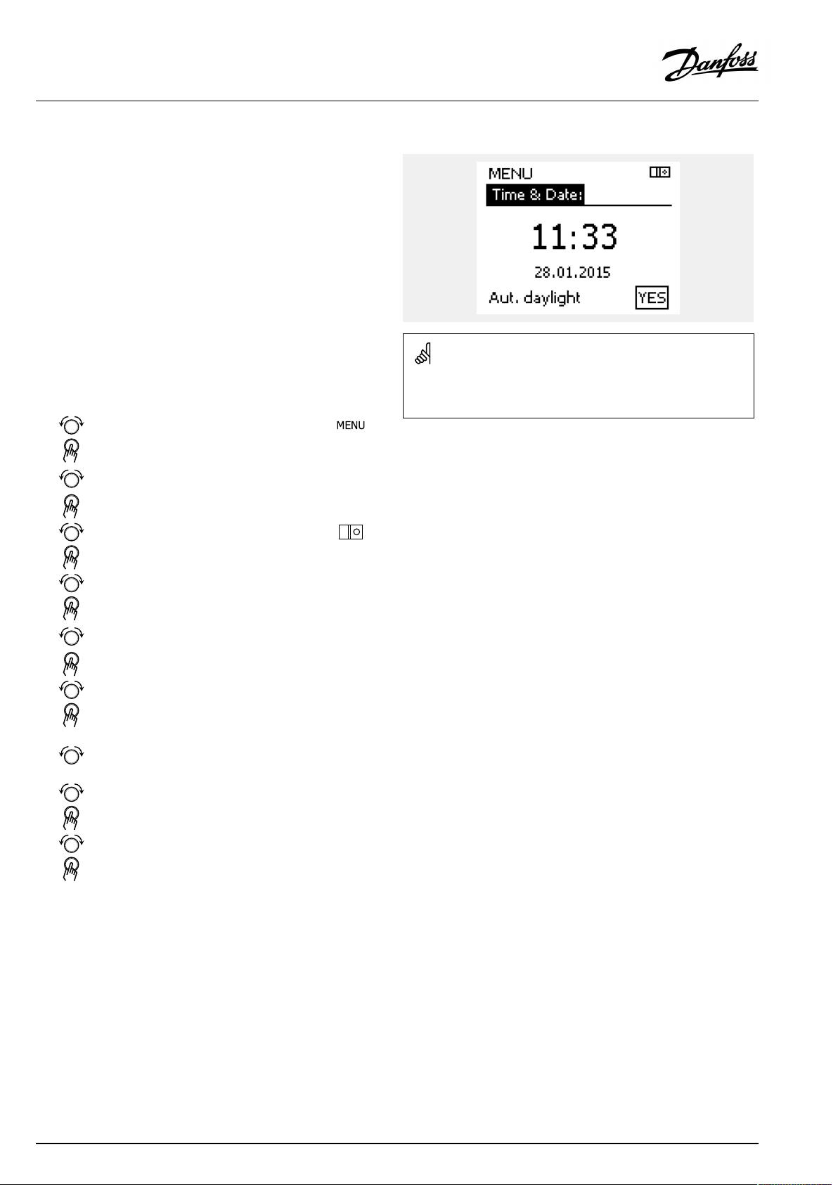
OperatingGuideECLComfort310,applicationA361
6.2Time&Date
Itisonlynecessarytosetthecorrectdateandtimeinconnection
withthefirstuseoftheECLComfortcontrollerorafterapower
breakofmorethan72hours.
Thecontrollerhasa24hourclock.
Aut.daylight(Daylightsavingtimechangeover)
YES:
NO:
Thecontroller’sbuilt-inclockautomaticallychanges+/
-onehouronthestandardizeddaysfordaylightsaving
timechangeoverforCentralEurope.
Youchangemanuallybetweensummerandwintertime
bysettingtheclockbackwardorforward.
Howtosettimeanddate:
Action:
Purpose:
Choose‘MENU’
Confirm
Choosethecircuitselectoratthetop
rightcornerinthedisplay
Confirm
Choose'Commoncontrollersettings'
Confirm
Goto‘Time&Date’
Confirm
Placethecursoratthepositiontobe
changed
Confirm
Enterthedesiredvalue
Confirm
Movethecursortothenextposition
tobechanged.Continueuntil‘Time&
Date’hasbeenset.
Finallymovethecursorto‘MENU’
Whencontrollersareconnectedasslavesinamaster/slavesystem
Examples:
(viaECL485communicationbus),theywillreceive‘Time&Date’from
themaster.
90|©Danfoss|2021.02
Confirm
Movethecursorto‘HOME’
Confirm
AQ000086455681en-010402
Page 91

OperatingGuideECLComfort310,applicationA361
6.3Holiday
ThissectiondescribesthefunctioningeneralfortheECLComfort
210/296/310series.Theshowndisplaysaretypicalandnot
applicationrelated.Theymightdifferfromthedisplaysinyour
application.
Thereisaholidayprogramforeachcircuitandaholidayprogram
forthecommoncontroller.
Eachholidayprogramcontainsoneormoreschedules.Each
schedulecanbesettoastartdateandanenddate.Thesetperiod
startsonthestartdateat00.00andstopsontheenddateat00.00.
SelectablemodesareComfort,Saving,FrostprotectionorComfort
7-23(before7andafter23,themodeisscheduled).
Howtosetyourholidayschedule:
Action:
Purpose:
Examples:
Choose‘MENU’
Confirm
Choosethecircuitselectoratthetop
rightcornerinthedisplay
Confirm
Chooseacircuitor'Commoncontroller
settings'
Heating
DHW
Commoncontrollersettings
Confirm
Goto‘Holiday’
Confirm
Theholidayprograminthe‘Commoncontrollersettings’isvalidfor
allcircuits.Theholidayprogramcanalsobesetindividuallyinthe
heatingorDHWcircuits.
Theenddatemustbeatleastbeonedaylaterthanthestartdate.
Chooseaschedule
Confirm
Confirmchoiceofmodeselector
Choosemode
Comfort
·Comfort7–23
Saving
·Frostprotection
Confirm
Enterthestarttimefirstandthenthe
endtime
Confirm
Goto‘Menu’
Confirm
Choose‘Yes’or‘No’in‘Save’ .Choose
thenextschedule,ifrequired
AQ000086455681en-010402
©Danfoss|2021.02|91
Page 92

OperatingGuideECLComfort310,applicationA361
Holiday,specificcircuit/CommonController
Whensettingoneholidayprograminspecificcircuitandanother
holidayprograminCommonController,aprioritywillbetaken
intoaccount:
1.Comfort
2.Comfort7-23
3.Saving
4.Frostprotection
Holiday,deletingasetperiod:
•ChoosetheScheduleinquestion
•Changethemodeto"Clock"
•Confirm
Example1:
Circuit1:
Holidaysetto"Saving"
CommonController:
Holidaysetto"Comfort"
Result:
Aslongas"Comfort"isactiveinCommonController,circuit1willbein
"Comfort".
Example2:
Circuit1:
Holidaysetto"Comfort"
CommonController:
Holidaysetto"Saving"
Result:
Aslongas"Comfort"isactiveincircuit1,itwillbein"Comfort".
Example3:
Circuit1:
Holidaysetto"Frostprotection"
TheECA30/31cannotoverridetheholidayscheduleofthe
controllertemporarily.
However,itispossibletomakeuseofthefollowingoptionsfrom
theECA30/31whenthecontrollerisinscheduledmode:
Dayoff
Holiday
Relaxing(extendedcomfortperiod)
Goingout(extendedsavingperiod)
CommonController:
Holidaysetto"Saving"
Result:
Aslongas"Saving"isactiveinCommonController,circuit1willbe
in"Saving".
Energy-savingtrick:
Use'Goingout'(theextendedsavingperiod)forairingpurposes(e.g.
forventilatingtheroomsbymeansoffreshairfromopenwindows).
ConnectionsandsetupproceduresforECA30/31:
Seesection'Miscellaneous'.
Quickguide"ECA30/31tooverridemode":
1.GotoECAMENU
2.Movecursorto"Clock"symbol
3.Selectthe"Clock"symbol
4.Chooseandselectoneof4overridefunctions
5.Belowtheoverridesymbol:Sethoursordate
6.Belowhours/date:Setdesiredroomtemperaturefortheoverride
period
92|©Danfoss|2021.02
AQ000086455681en-010402
Page 93
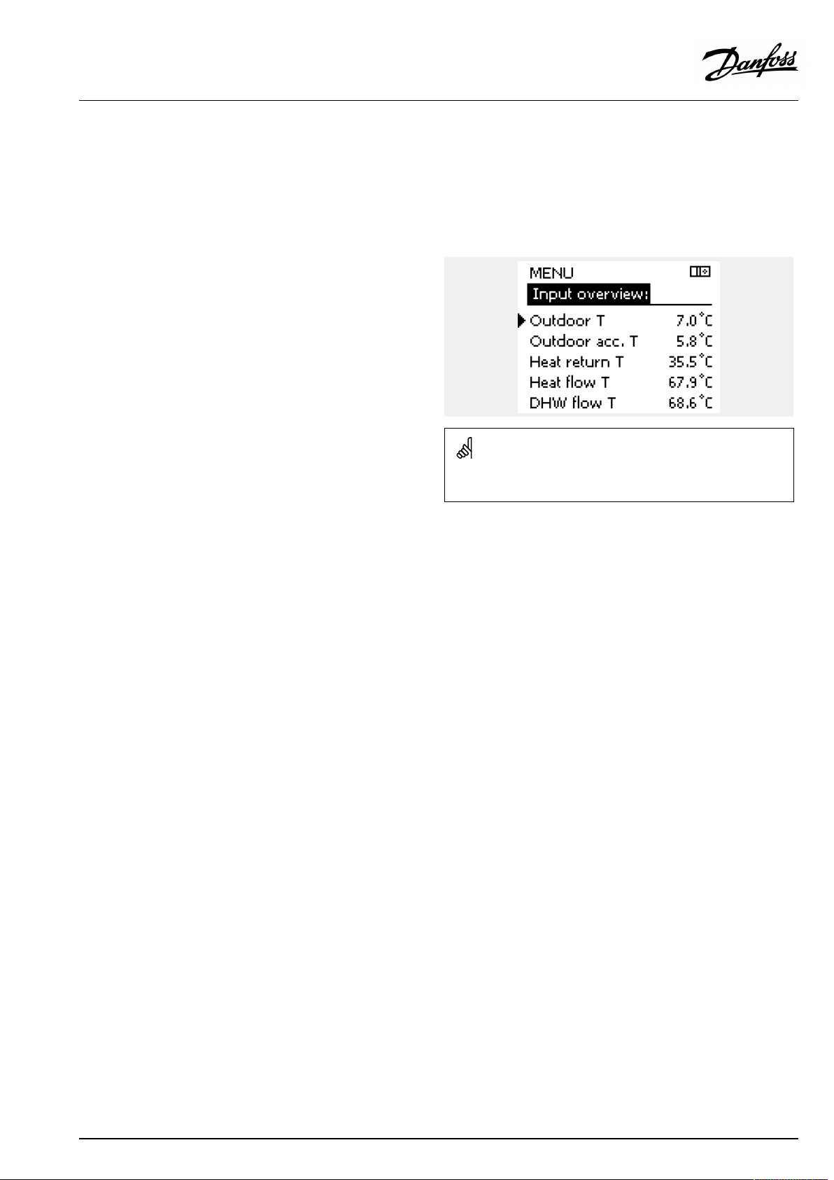
OperatingGuideECLComfort310,applicationA361
6.4Inputoverview
ThissectiondescribesthefunctioningeneralfortheECLComfort
210/296/310series.Theshowndisplaysaretypicalandnot
applicationrelated.Theymightdifferfromthedisplaysinyour
application.
Theinputoverviewislocatedinthecommoncontrollersettings.
Thisoverviewwillalwaysshowyoutheactualtemperaturesinthe
system(read-only).
"Outdooracc.T"means"Accummulatedoutdoortemperature"andis
acalculatedvalueintheECLComfortcontroller.
AQ000086455681en-010402
©Danfoss|2021.02|93
Page 94

OperatingGuideECLComfort310,applicationA361
6.5Log
ThissectiondescribesthefunctioningeneralfortheECLComfort
210/296/310series.Theshowndisplaysaretypicalandnot
applicationrelated.Theymightdifferfromthedisplaysinyour
application.
Thelogfunction(temperaturehistory)allowsyoutomonitorthe
logsoftoday,yesterday,thepast2daysaswellasthepast4days
fortheconnectedsensors.
Thereisalogdisplayfortherelevantsensor,showingthemeasured
temperature.
Thelogfunctionisonlyavailableinthe'Commoncontroller
settings'.
Example1:
1daylogforyesterdayshowingthedevelopmentinoutdoor
temperatureduringthepast24hours.
Example2:
Today’slogfortheactualheatingflowtemperatureaswellasthe
desiredtemperature.
Example3:
Yesterday’slogfortheDHWflowtemperatureaswellasthedesired
temperature.
94|©Danfoss|2021.02
AQ000086455681en-010402
Page 95

OperatingGuideECLComfort310,applicationA361
6.6Outputoverride
ThissectiondescribesthefunctioningeneralfortheECLComfort
210/296/310series.Theshowndisplaysaretypicalandnot
applicationrelated.Theymightdifferfromthedisplaysinyour
application.
Theoutputoverrideisusedtodisableoneormoreofthecontrolled
components.Thiscouldamongothersbeusefulinaservice
situation.
Action:Purpose:
Choose'MENU'inanyoftheoverview
displays
Confirm
Choosethecircuitselectoratthetop
rightcornerinthedisplay
Confirm
Choosecommoncontrollersettings
Confirm
Choose'Outputoverride'
Confirm
Chooseacontrolledcomponent
Confirm
Adjustthestatusofthecontrolled
component:
Motorizedcontrolvalve:AUTO,STOP ,
CLOSE,OPEN
Pump:AUTO,OFF ,ON
Confirmstatuschange
Examples:
M1,P1etc.
ControlledcomponentsCircuitselector
"Manualcontrol"hashigherprioritythan"Outputoverride".
Whentheselectedcontrolledcomponent(output)isnot‘AUTO’ ,the
ECLComfortcontrollerdoesnotcontrolthecomponentinquestion
(pumpormotorizedcontrolvalvee.g.).Frostprotectionisnotactive.
Remembertochangethestatusbackagainassoonasanoverride
isnotrequiredanylonger.
AQ000086455681en-010402
Whenoutputoverrideofacontrolledcomponentisactivethesymbol
‘!’isshowntotherightofthemodeindicatorintheenduserdisplays.
©Danfoss|2021.02|95
Page 96

OperatingGuideECLComfort310,applicationA361
6.7Keyfunctions
NewapplicationEraseapplication:
ApplicationGivesanoverviewovertheactual
FactorysettingSystemsettings:
Copy
Keyoverview
Removestheexistingapplication.As
soonastheECLkeyisinserted,another
applicationcanbechosen.
applicationintheECLcontroller.Push
thedialagaintoexittheoverview.
Systemsettingsare,amongothers,
communicationset-up,display
brightnessetc.
Usersettings:
Usersettingsare,amongothers,desired
roomtemperature,desiredDHW
temperature,schedules,heatcurve,
limitationvaluesetc.
Gotofactory:
Restoresthefactorysettings.
To:
Copydirection
Systemsettings
Usersettings
Startcopying
GivesanoverviewovertheinsertedECL
key.(Example:A266Ver.2.30).
Turnthedialtoseethesubtypes.Push
thedialagaintoexittheoverview.
Amoredetaileddescriptionofhowtousetheindividual‘Key
functions’canalsobeseenin‘InsertingtheECLapplicationkey’ .
96|©Danfoss|2021.02
AQ000086455681en-010402
Page 97

OperatingGuideECLComfort310,applicationA361
The“Keyoverview”doesnotinform—throughECA30/31—about
thesubtypesoftheapplicationkey.
Keyinserted/notinserted,description:
ECLComfort210/310,controllerversionslowerthan1.36:
-
Takeouttheapplicationkey;for20minutes
settingscanbechanged.
-
Powerupthecontrollerwithoutthe
applicationkeyinserted;for20minutes
settingscanbechanged.
ECLComfort210/310,controllerversions1.36andup:
-
Takeouttheapplicationkey;for20minutes
settingscanbechanged.
-
Powerupthecontrollerwithoutthe
applicationkeyinserted;settingscannotbe
changed.
ECLComfort296,controllerversions1.58andup:
-
Takeouttheapplicationkey;for20minutes
settingscanbechanged.
-
Powerupthecontrollerwithoutthe
applicationkeyinserted;settingscannotbe
changed.
AQ000086455681en-010402
©Danfoss|2021.02|97
Page 98

OperatingGuideECLComfort310,applicationA361
6.8System
6.8.1ECLversion
In‘ECLversion’youwillalwaysbeabletofindanoverviewofthe
datarelatedtoyourelectroniccontroller.
Pleasehavethisinformationavailableifyouneedtocontactyour
Danfosssalesorganizationconcerningthecontroller.
InformationaboutyourECLApplicationKeycanbefoundin‘Key
functions’and‘Keyoverview’ .
Codeno.:
Hardware:
Software:Software(firmware)versionof
Serialno.:
Productionweek:Weekno.andyear(WW.YYYY)
6.8.2Extension
ECLComfort310/310B:
‘Extension’willofferyouinformationaboutadditionalmodules,if
any.AnexamplecouldbetheECA32module.
TheDanfosssalesandorderno.
forthecontroller
Hardwareversionofthe
controller
thecontroller
Uniquenumberforthe
individualcontroller
Example,ECLversion
6.8.3Ethernet
ECLComfort296/310/310BhaveaModbus/TCPcommunication
interfacethatallowstheECLcontrollertobeconnectedtoan
Ethernetnetwork.ThisallowsremoteaccesstotheECL296/310/
310Bcontrollerbasedonstandardcommunicationinfrastructures.
In‘Ethernet’itispossibletosetuptherequiredIPaddresses.
6.8.4Portalconfig
ECLComfort296/310/310BhaveaModbus/TCPcommunication
interfacethatallowstheECLcontrollertobemonitoredand
controlledviatheECLPortal.
ECLPortalrelatedparametersaresethere.
DocumentationforECLPortal:Seehttps://ecl.portal.danfoss.com
6.8.5M-busconfig
ECLComfort296/310/310BhaveanM-buscommunication
interfacethatallowsenergymeterstobeconnectedasslaves.
M-busrelatedparametersaresethere.
98|©Danfoss|2021.02
AQ000086455681en-010402
Page 99

OperatingGuideECLComfort310,applicationA361
6.8.6EnergymeterandM-bus,generalinformation
ECLComfort296/310/310Bonly
WhenusingtheApplicationKeyintheECLComfort296/310
/310B,upto5energymeterscanbeconnectedtotheM-bus
connections.
Connectionofenergymetercan:
•limittheflow
•limitthepower
•transferenergymeterdatatotheECLPortal,viaEthernet,and/
oraSCADAsystem,viaModbus.
Manyapplicationswithcontrolofheating,DHWorcoolingcircuit
havethepossibilitytoreactonenergymeterdata.
Toverifyifactualapplicationkeycanbesettoreactonenergy
meterdata:
SeeCircuit>MENU>Settings>Flow/power.
TheECLComfort296/310/310Bcanalwaysbeusedfor
monitoringpurposeofupto5energymeters.
TheECLComfort296/310/310BactasanM-busmasterandmust
besettocommunicatewithconnectedenergymeter(s).
SeeMENU>Commoncontroller>System>M-busconfig.
EnergymeterdataacquisitionfromECLPortalispossiblewithout
settinguptheM-busconfiguration.
Technicalinfo:
•TheM-busdataarebasedonstandardEN-1434.
•DanfossrecommendsACsuppliedenergymetersinorderto
avoidbatterydraining.
MENU>Commoncontroller>System>M-busconfig.
State
CircuitSettingrange
Read-out
Factorysetting
---
InformationaboutthecurrentM-busactivity.
IDLE:
INIT:
SCAN:
GATEW:
Normalstate
Thecommandforinitializationhasbeenactivated
Thecommandforscanninghasbeenactivated
ThecommandGatewayhasbeenactivated
MENU>Commoncontroller>System>M-busconfig.
TheECLComfort296/310/310BwillreturntoIDLEwhencommands
havebeencompleted.
Gatewayisusedforread-outofenergymeterviaECLPortal.
Baud(bitspersecond)
CircuitSettingrange
-
300/600/1200/2400
ThecommunicationspeedbetweenECLComfort296/310/310B
andtheconnectedenergymeter(s).
AQ000086455681en-010402
5997
Factorysetting
300
Typically,300or2400baudisused.
IfECLComfort296/310/310BareconnectedtotheECLPortal,abaud
rateof2400isrecommendable,providedtheenergymeterallowsthis.
©Danfoss|2021.02|99
Page 100

OperatingGuideECLComfort310,applicationA361
MENU>Commoncontroller>System>M-busconfig.
Command
CircuitSettingrange
-
NONE/INIT/SCAN/GA TEWNONE
Factorysetting
TheECLComfort296/310/310BareM-busmasters.Inordertoverify
connectedenergymeters,differentcommandscanbeactivated.
NONE:
INIT:
SCAN:
Nocommandactivated
Initializationisactivated
Scanningisactivatedinordertosearchforconnected
energymeters.TheECLComfort296/310/310B
detecttheM-busaddressesofupto5connected
energymetersandplacetheseautomaticallyinthe
"Energymeters"section.Theverifiedaddressisplaced
after"Energymeter1(2,3,4,5)"
GATEW:
TheECLComfort296/310/310Bactasagateway
betweenenergymetersandECLPortal.Usedonlyfor
service.
MENU>Commoncontroller>System>M-busconfig.
M-busaddress
Energymeter1(2,3,4,5)
CircuitSettingrange
-
0-255255
Factorysetting
Thesetorverifiedaddressofenergymeter1(2,3,4,5).
5998
Scantimecantakeupto12minutes.
Whenallenergymetersarefound,thecommandcanbechanged
toINITorNONE.
6000
0:
1-250:
251-254:
Normallynotused
ValidM-busaddresses
Specialfunctions.UseonlyM-busaddress254when
oneenergymeterisconnected.
255:
Notused
MENU>Commoncontroller>System>M-busconfig.
Type
Energymeter1(2,3,4,5)
CircuitSettingrange
-
0-40
Factorysetting
SelectingdatarangefromtheM-bustelegram..
0:
1:
2:
3:
4:
Smalldataset,smallunits
Smalldataset,largeunits
Largedataset,smallunits
Largedataset,largeunits
Volumeandenergydataonly
(example:HydroPortPulse)
6001
Dataexamples:
0:
Flowtemp.,returntemp.,flow,power,acc.volume,acc.energy.
3:
Flowtemp.,returntemp.,flow,power,acc.volume,acc.energy,
tariff1,tariff2.
Seealsothe"Instructions,ECLComfort210/310,communication
description"forfurtherdetails.
SeealsoAppendixfordetaileddescriptionof"Type".
100|©Danfoss|2021.02
AQ000086455681en-010402
 Loading...