

Page 1
OperatingGuide
ECLComfort210/296/310,applicationA247/A347
1.0TableofContents
1.0TableofContents...............................................1
1.1Importantsafetyandproductinformation.....................2
2.0Installation........................................................6
2.1Beforeyoustart.....................................................6
2.2Identifyingthesystemtype......................................15
2.3Mounting...........................................................21
2.4Placingthetemperaturesensors................................25
2.5Electricalconnections.............................................27
2.6InsertingtheECLApplicationKey..............................36
2.7Checklist............................................................43
2.8Navigation,ECLApplicationKeyA247/A347................44
3.0Dailyuse.........................................................50
3.1Howtonavigate...................................................50
3.2Understandingthecontrollerdisplay..........................51
3.3Ageneraloverview:Whatdothesymbolsmean?...........55
3.4Monitoringtemperaturesandsystem
components........................................................56
3.5Influenceoverview................................................57
3.6Manualcontrol.....................................................58
3.7Schedule............................................................59
4.0Settingsoverview............................................60
5.0Settings...........................................................63
5.1IntroductiontoSettings..........................................63
5.2Flowtemperature..................................................64
5.3Roomlimit..........................................................68
5.4Returnlimit.........................................................70
5.5Flow/powerlimit.................................................76
5.6Optimization........................................................81
5.7Controlparameters................................................88
5.8Application.........................................................93
5.9Heatcut-out......................................................104
5.10Tanktemperature................................................107
5.11Alarm..............................................................112
5.12Alarmoverview..................................................115
5.13Anti-bacteria......................................................116
6.0Commoncontrollersettings............................118
6.1Introductionto‘Commoncontrollersettings’..............118
6.2Time&Date.......................................................119
6.3Holiday............................................................120
6.4Inputoverview...................................................122
6.5Log.................................................................123
6.6Outputoverride..................................................124
6.7Keyfunctions.....................................................125
6.8System.............................................................127
7.0Miscellaneous................................................134
7.1ECA30/31setupprocedures.................................134
7.2Overridefunction................................................142
7.3Severalcontrollersinthesamesystem......................145
7.4Frequentlyaskedquestions....................................148
7.5Definitions........................................................151
7.6Type(ID6001),overview.......................................155
7.7Automatic/manualupdateoffirmware.....................156
7.8ParameterIDoverview..........................................157
©Danfoss|2021.12AQ192386469094en-010802|1
Page 2

OperatingGuideECLComfort210/296/310,applicationA247/A347
1.1Importantsafetyandproductinformation
ThisInstallationGuideisassociatedwithECLApplicationKeyA247
(ordercodeno.087H3808).
TheA247Keycontains6subtypes:
A247.1…A247.3(applicableinECLComfort210and310)
A347.1…A347.3(applicableinECLComfort310)
•A247.1:HeatingandDHWcharging/heating
•A247.2:HeatingandDHWcharging
•A247.3:HeatingandadvancedDHWcharging
•A347.1:HeatingandDHWcharging/heating.M-busoptional
•A347.2:HeatingandDHWcharging.M-busoptional
•A347.3:HeatingandDHWcharging.MonitoringofDHW
circulationreturn.M-busoptional
TheA247applicationkeyalsocontainsaFloor(Screed)Drying
Program.Seeseparatedocumentation.
SeetheMountingGuide(deliveredwiththeapplicationkey)for
applicationexamplesandelectricalconnections.
ThedescribedfunctionsarerealizedinECLComfort210forbasic
solutionsandinECLComfort310foradvancedsolutions,for
exampleM-bus,ModbusandEthernet(Internet)communication.
TheapplicationKeyA247complieswithECLComfort210and
ECLComfort310controllersasofsoftwareversion1.11(visible
atstart-upofthecontrollerandin'Commoncontrollersettings'
in'System').
UptotwoRemoteControlUnits,ECA30orECA31,canbe
connectedandthebuilt-inroomtemperaturesensorcanbe
utilized.
TogetherwiththeECLComfort310,theadditionalInternalI/O
moduleECA32(ordercodeno.087H3202)canbeusedforextra
datacommunicationtoSCADA:
•Temperature,Pt1000(default)
•0-10voltsignals
Theset-upofinputtypecanbedonebymeansoftheDanfoss
Software"ECLTool".
Navigation:Danfoss.com>Products&Solutions>DistrictHeating
andCooling>T ools&Software>ECLTool.
TheURLis:
https://www.danfoss.com/en/service-and-support/downloads/
TheInternalI/OmoduleECA32isplacedinthebasepartforECL
Comfort310.
ECLComfort210isavailableas:
•ECLComfort210,230volta.c.(087H3020)
•ECLComfort210B,230volta.c.(087H3030)
ECLComfort310isavailableas:
•ECLComfort310,230volta.c.(087H3040)
•ECLComfort310B,230volta.c.(087H3050)
•ECLComfort310,24volta.c.(087H3044)
AdditionaldocumentationforECLComfort210and310,modules
andaccessoriesisavailableonhttp://danfoss.com/.
2|©Danfoss|2021.12
AQ192386469094en-010802
Page 3
OperatingGuideECLComfort210/296/310,applicationA247/A347
TheB-typeshavenodisplayanddial.TheB-typesareoperatedby
meansoftheRemoteControlunitECA30/31:
•ECA30(087H3200)
•ECA31(087H3201)
BasepartsforECLComfort:
•forECLComfort210,230volta.c.(087H3220)
•forECLComfort296,230volta.c.(087H3240)
•forECLComfort310,230volta.c.and24volta.c(087H3230)
AdditionaldocumentationforECLComfort210,296and310,
modulesandaccessoriesisavailableonhttp://danfoss.com/.
DocumentationforECLPortal:Seehttps://ecl.portal.danfoss.com.
Applicationkeysmightbereleasedbeforealldisplaytextsare
translated.InthiscasethetextisinEnglish.
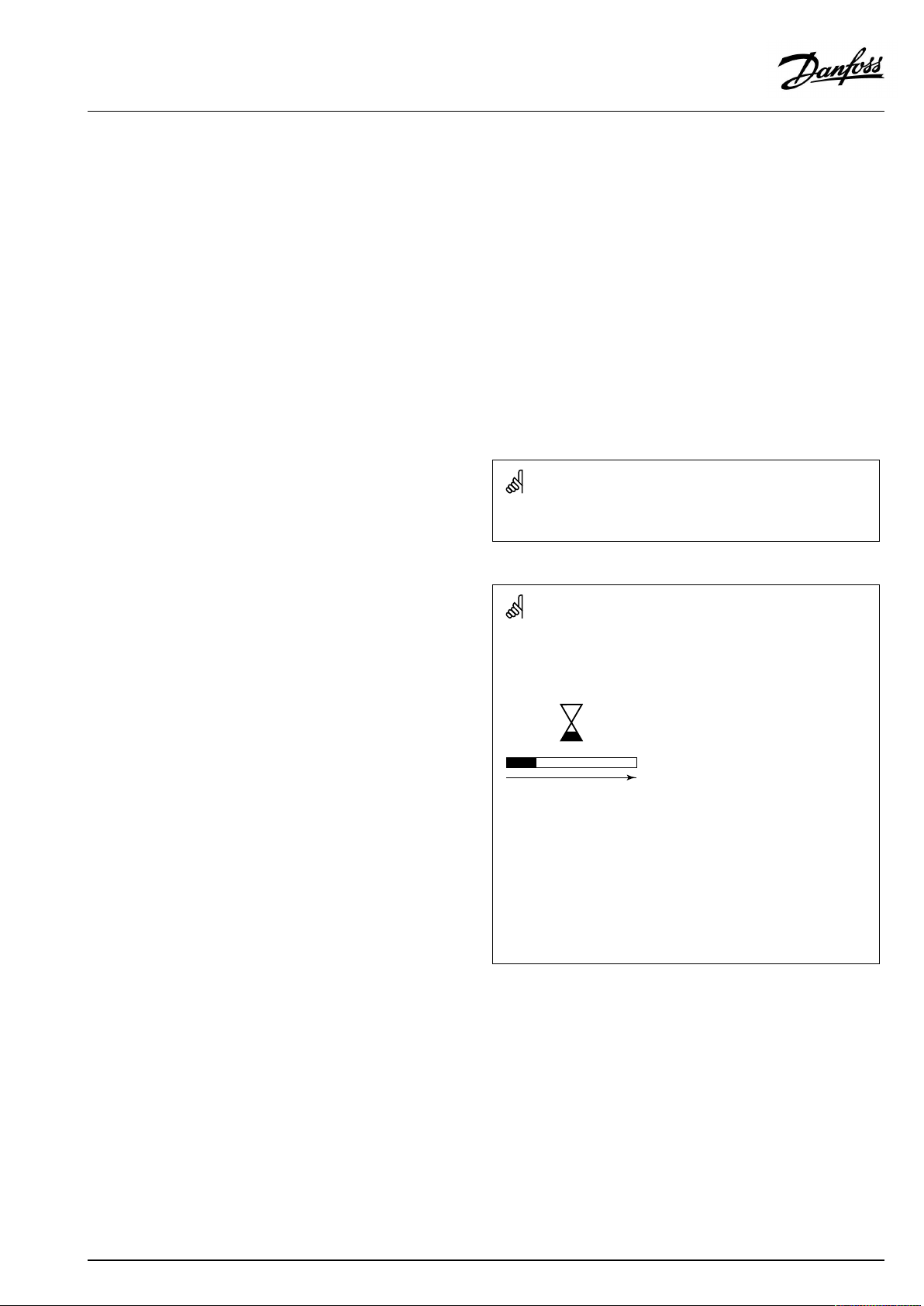
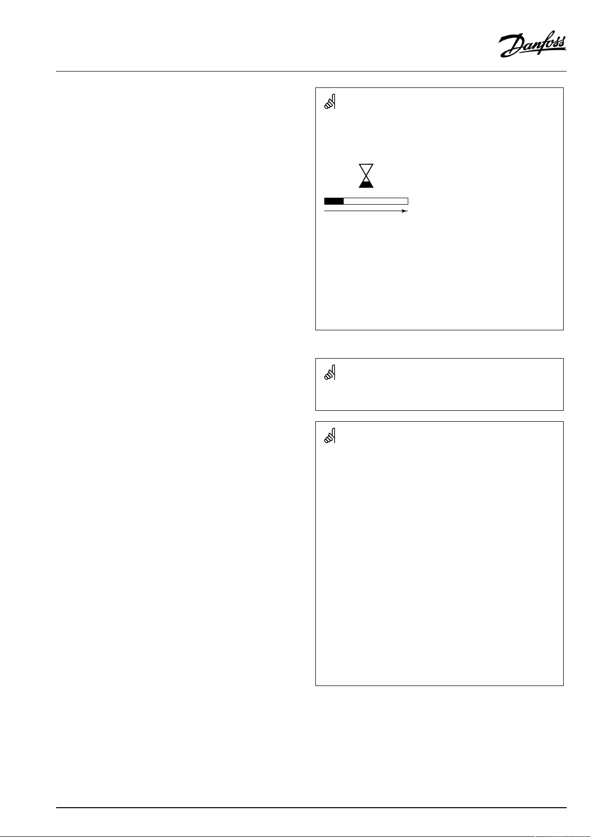
Automaticupdateofcontrollersoftware(firmware):
Thesoftwareofthecontrollerisupdatedautomaticallywhenthekey
isinserted(asofcontrollerversion1.11(ECL210/310)andversion
1.58(ECL296)).Thefollowinganimationwillbeshownwhenthe
softwareisbeingupdated:
Progressbar
Duringupdate:
•DonotremovetheKEY
Ifthekeyisremovedbeforethehour-glassisshown,youhave
tostartafresh.
•Donotdisconnectthepower
Ifthepowerisinterruptedwhenthehour-glassisshown,the
controllerwillnotwork.
•Manualupdateofcontrollersoftware(firmware):
Seethesection"Automatic/manualupdateoffirmware"
AQ192386469094en-010802
©Danfoss|2021.12|3
Page 4
OperatingGuideECLComfort210/296/310,applicationA247/A347
SafetyNote
Toavoidinjuryofpersonsanddamagestothedevice,itisabsolutely
necessarytoreadandobservetheseinstructionscarefully.
Necessaryassembly,start-up,andmaintenanceworkmustbe
performedbyqualifiedandauthorizedpersonnelonly.
Locallegislationsmustberespected.Thiscomprisesalsocable
dimensionsandtypeofisolation(doubleisolatedat230V).
AfusefortheECLComfortinstallationismax.10Atypically.
TheambienttemperaturerangesforECLComfortinoperationare:
ECLComfort210/310/311:0-55°C
ECLComfort296:0-45°C.
Exceedingthetemperaturerangecanresultinmalfunctions.
Installationmustbeavoidedifthereisariskforcondensation(dew).
Thewarningsignisusedtoemphasizespecialconditionsthatshould
betakenintoconsideration.
Thissymbolindicatesthatthisparticularpieceofinformationshould
bereadwithspecialattention.
AsthisOperatingGuidecoversseveralsystemtypes,specialsystem
settingswillbemarkedwithasystemtype.Allsystemtypesareshown
inthechapter:'Identifyingyoursystemtype'.
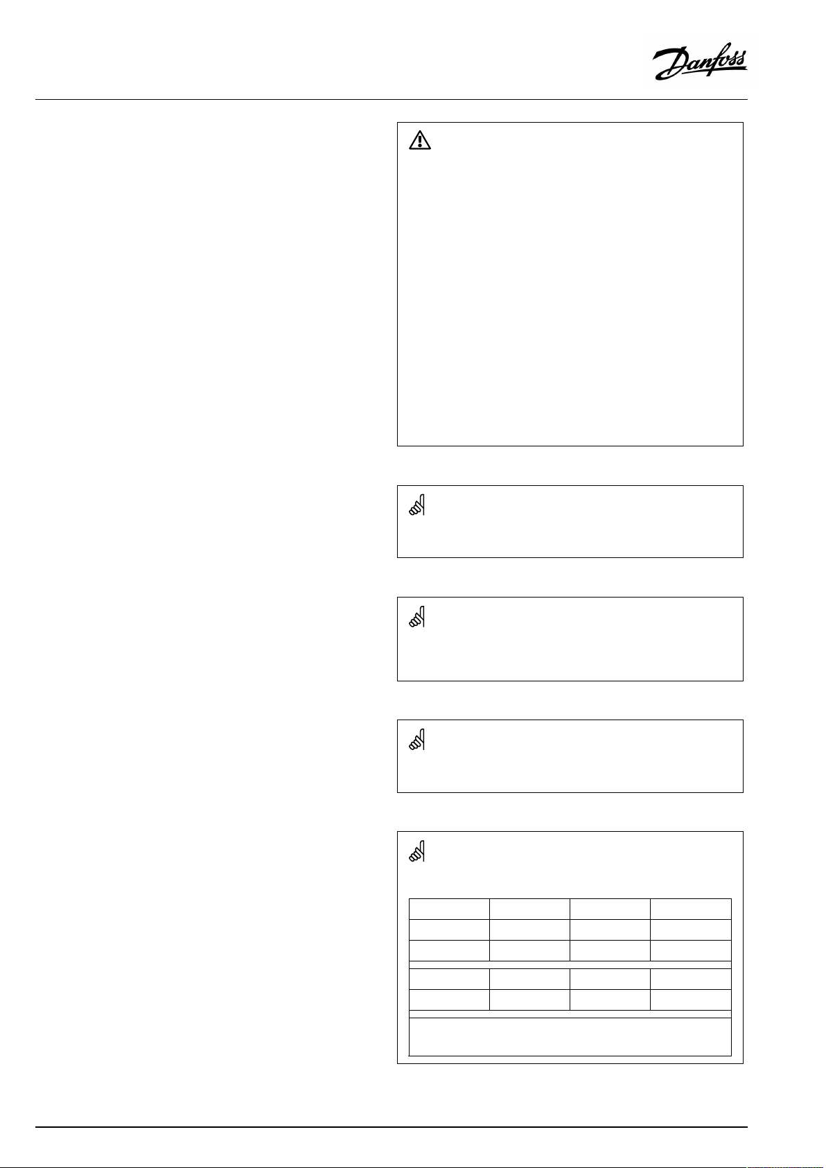
°C(degreesCelsius)isameasuredtemperaturevaluewhereasK
(Kelvin)oftenisusedfortemperaturedifferences.
TheIDno.isuniquefortheselectedparameter.
ExampleFirstdigitSeconddigitLastthreedigits
1117411174
-
Circuit1Parameterno.
4|©Danfoss|2021.12
12174
IfanIDdescriptionismentionedmorethanonce,itmeansthatthere
arespecialsettingsforoneormoresystemtypes.Itwillbemarked
withthesystemtypeinquestion(e.g.12174-A266.9).
1
-
2
Circuit2Parameterno.
174
AQ192386469094en-010802
Page 5
OperatingGuideECLComfort210/296/310,applicationA247/A347
ParametersindicatedwithanIDno.like"1x607"meanauniversal
parameter.
xstandsforcircuit/parametergroup.
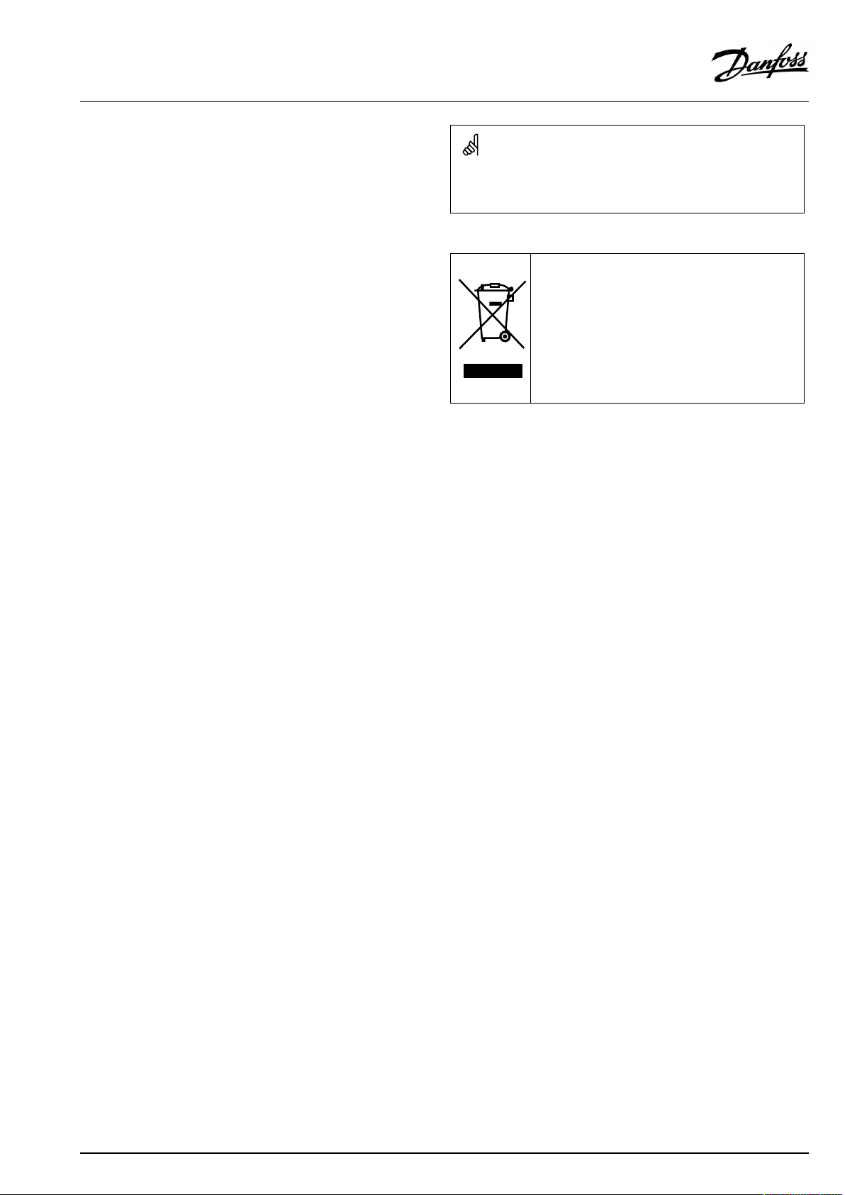
DisposalNote
Thissymbolontheproductindicatesthatitmaynot
bedisposedofashouseholdwaste.
Itmustbehandedovertotheapplicabletake-back
schemefortherecyclingofelectricalandelectronic
equipment.
•Disposeoftheproductthroughchannelsprovided
forthispurpose.
•Complywithalllocalandcurrentlyapplicablelaws
andregulations.
AQ192386469094en-010802
©Danfoss|2021.12|5
Page 6
OperatingGuideECLComfort210/296/310,applicationA247/A347
2.0Installation
2.1Beforeyoustart
Theapplications(subtypes)intheA247applicationkeyarevery
flexibleandalmostidentical.However,someapplicationshave
extrafunctionswhicharedescribedseparately.
Thesearethebasicprinciples:
Heating(circuit1):
Typically,theflowtemperatureisadjustedaccordingtoyour
requirements.TheflowtemperaturesensorS3isthemost
importantsensor.ThedesiredflowtemperatureatS3iscalculated
intheECLcontroller,basedontheoutdoortemperatureS1andthe
desiredroomtemperature.Thelowertheoutdoortemperature,
thehigherthedesiredflowtemperature.
Bymeansofaweekschedule(upto3‘Comfort’periods/day),the
heatingcircuitcanbein‘Comfort’or‘Saving’mode(twodifferent
temperaturevaluesfordesiredroomtemperature).
InSavingmodetheheatingcanbereducedorswitchedofftotally.
ThemotorizedcontrolvalveM2isopenedgraduallywhenthe
flowtemperatureislowerthanthedesiredflowtemperatureand
viceversa.
Thereturntemperature(S5)tothedistrictheatingsupplyshould
notbetoohigh.Ifso,thedesiredflowtemperaturecanbeadjusted
(typicallytoalowervalue),thusresultinginagradualclosingofthe
motorizedcontrolvalve.
Inboiler-basedheatingsupplythereturntemperatureshouldnot
betoolow(sameadjustmentprocedureasabove).
Furthermore,thereturntemperaturelimitationcanbedependent
oftheoutdoortemperature.Typically,thelowertheoutdoor
temperature,thehighertheacceptedreturntemperature.
Ifthemeasuredroomtemperature(RemotecontrolunitECA30/
31)doesnotequalthedesiredroomtemperature,thedesiredflow
temperaturecanbeadjusted.
Thecirculationpump(P1)isONatheatdemandoratfrost
protection.
TheheatingcanbeswitchedOFFwhentheoutdoortemperatureis
higherthanaselectablevalue.
A247.1,A247.2:
Aconnectedfloworenergymeterbasedonpulses(S7)canlimit
thefloworenergytoasetmaximumvalue.Furthermore,the
limitationcanbeinrelationtotheoutdoortemperature.
Typically,thelowertheoutdoortemperature,thehigherthe
acceptedflow/power.
WhenthesubtypesA347.1-A347.3areused(onlyinECLComfort
310),theflow/powersignalcancomeasanM-bussignal.
Thefrostprotectionmodemaintainsaselectableflowtemperature,
forexample10°C.
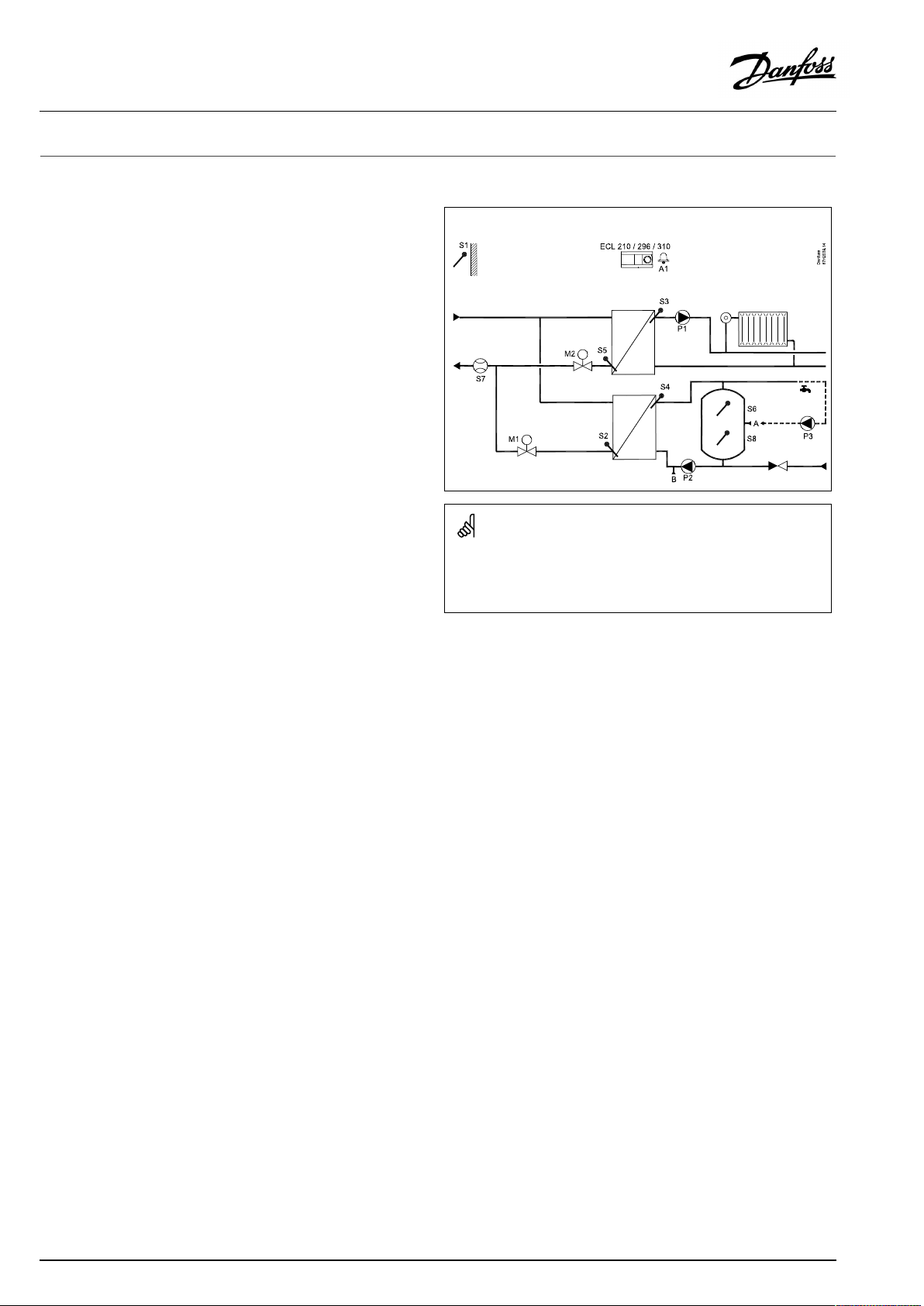
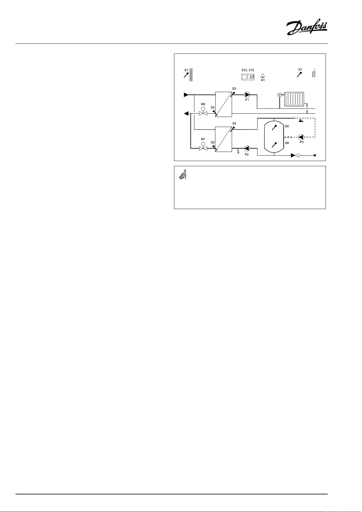
TypicalA247.1application,examplea:
Theshowndiagramisafundamentalandsimplifiedexampleanddoes
notcontainallcomponentsthatarenecessaryinasystem.
AllnamedcomponentsareconnectedtotheECLComfortcontroller.
Listofcomponents:
ECL210/310
S1
S2DHWreturntemperaturesensor,circuit2
S3
S4
S5Returntemperaturesensor,circuit1
S6
S7
S8
P1
P2
P3
M1
M2
A1
A/B
ElectroniccontrollerECLComfort210or310
Outdoortemperaturesensor
Flowtemperaturesensor,circuit1
DHWflowtemperaturesensor,circuit2
DHWtanktemperaturesensor,upper
Flow/energymeter(pulsesignal)
DHWtanktemperaturesensor,lower
Circulationpump,heating,circuit1
Chargingpump,DHW,circuit2
Circulationpump,DHW,circuit2
Motorizedcontrolvalve(3-pointcontrolled),circuit2
Alternative:Thermoactuator(DanfosstypeABV)
Motorizedcontrolvalve(3-pointcontrolled),circuit1
Alternative:Thermoactuator(DanfosstypeABV)
Alarm
Internal/externalconnectionsforDHWcirculation
Analarmcanbeactivatediftheactualflowtemperaturediffers
fromthedesiredflowtemperature.
6|©Danfoss|2021.12
AQ192386469094en-010802
Page 7

OperatingGuideECLComfort210/296/310,applicationA247/A347
A247.1,A247.2,A247.3:
TheroomtemperaturesignalcanbeachievedfromtheRemote
ControlUnitECA30/31,ifconnected.
A347.1,A347.2,A347.3:
Theroomtemperaturesignalcanbeachievedfromtheroom
temperaturesensorS7ortheRemoteControlUnitECA30/31,if
connected.
A347.1,A347.2,A347.3:
Thedesiredflowtemperatureofheatingcircuit1can,viaS10,be
controlledbymeansofanexternalvoltageintherange0-10volt.
Heatingcircuit,ingeneral:
Exerciseofcirculationpumpandcontrolvalveinperiodswithout
heatingdemandcanbearranged.
AQ192386469094en-010802
©Danfoss|2021.12|7
Page 8
OperatingGuideECLComfort210/296/310,applicationA247/A347
DomesticHotWater ,DHW(circuit2):
Bymeansofaweekschedule(upto3‘Comfort’periods/day),the
DHWcircuitcanbein‘Comfort’or‘Saving’mode(twodifferent
temperaturevaluesfordesiredDHWtemperature).
Chargingstart,DHWtankwith1or2temperaturesensors
WhenthemeasuredDHWtemperatureS6getslowerthanthe
charging-starttemperature,theDHWchargingpump(P2)is
switchedON.
Themotorizedcontrolvalve(M1)iscontrolledinordertomaintain
thechargingtemperatureatS4.
Adelayedstartofchargingpumpcanbearranged.Also,itcan
bearrangedthatthestartofthechargingpumpdependson
thechargingtemperature.Inthiscase,S4mustbeplacedinthe
heat-exchanger.
TheDHWchargingtemperatureisdeterminedbythedesiredDHW
temperatureatS6plusthesetchargingdifference.Thecharging
temperatureistypically5–10degreeshigherthanthedesired
DHWtemperature.
Thereturntemperature,whentheDHWheating/chargingis
active,canbelimitedtoafixedvalue.
A247.2:
WhenthemeasuredDHWtemperatureS6getslowerthanthe
charging-starttemperature,theDHWheatingpump(P2)is
switchedONandthemotorizedcontrolvalveM1iscontrolledin
ordertomaintainthechargingtemperatureatS4.Thecharging
pumpisswitchedONwhentheS4temperatureisacceptable.
A247.1,examplea
Charging-starttemperature:
DesiredDHWtemperature+Startdifference.
Example:
50°C+(-3K)=47°C
A247.3:
TheDHWheatingcircuithasapreheatingcircuit,wheretheDHW
heatingtemperatureatS4isadaptedtothedesiredDHWcharging
temperatureatS7.IftheDHWchargingtemperatureatS7cannot
bereached,theECLcontrollergraduallyincreasesthedesiredDHW
heatingtemperatureatS4inordertoobtaintheDHWcharging
temperature.TheECLcontrollerrememberstheadaptedS4
temperature.Amaximumtemperaturevaluecanbeset.
A347.2:
TheDHWheatingcircuithasapreheatingcircuit,wheretheDHW
heatingtemperatureatS4isadaptedtothedesiredDHWcharging
temperatureatS9.IftheDHWchargingtemperatureatS9cannot
bereached,theECLcontrollergraduallyincreasesthedesiredDHW
heatingtemperatureatS4inordertoobtaintheDHWcharging
temperature.TheECLcontrollerrememberstheadaptedS4
temperature.Amaximumtemperaturevaluecanbeset.
8|©Danfoss|2021.12
AQ192386469094en-010802
Page 9

OperatingGuideECLComfort210/296/310,applicationA247/A347
Chargingstop,DHWtankwith1temperaturesensor:
WhenthemeasuredDHWtemperatureS6getshigherthan
thecharging-stoptemperature,theDHWchargingpumpP2is
switchedOFF.Apost-runtimecanbeset.
Chargingstop,DHWtankwith2temperaturesensors:
WhenthemeasuredDHWtemperatureS6gets2Khigherthan
thecharging-starttemperatureANDthelowertanktemperature
S8getshigherthanthecharging-stoptemperature,theDHW
chargingpumpP2isswitchedOFF.Apost-runtimecanbeset.
DHWcirculation
InchargingapplicationstheDHWcirculationcanbethrough
theDHWtank(connectionA)orthroughtheheat-exchanger
(connectionB).
ThesolutionwithconnectionAresultsinclosingofthemotorized
controlvalveaftertheDHWtankchargingprocedure.
ThesolutionwithconnectionBstopstheDHWchargingpump
aftertheDHWtankchargingprocedure.Thetemperatureatthe
chargingtemperaturesensorismaintainedaccordingtothevalue
ofthedesiredDHWtemperatureinordertocompensateforthe
heatlossintheDHWcirculationpipe.
Flow/powerlimitation
A247.1,A247.2:
Aconnectedfloworenergymeterbasedonpulses(S7)canlimit
thefloworpowertoasetmaximumvalue.
Charging-stoptemperature:
DesiredDHWtemperature+Stopdifference.
Example,S6only:
50°C+(3K)=53°C
Example,S6andS8:
50°C+(-8K)=42°C
A347.1,A347.2,A347.3(onlyinECLComfort310):
Theflow/powersignalcancomeasanM-bussignal.
Ananti-bacteriafunctionisavailableforactivationonselected
daysoftheweek.
TheDHWcirculationpumpP3hasaweekscheduleforupto3
ON-periodsperday.
IfthedesiredDHWtemperaturecannotbereached,theheating
circuitcanbeclosedgraduallytoallowmoreenergytotheDHW
circuit.
AQ192386469094en-010802
©Danfoss|2021.12|9
Page 10
OperatingGuideECLComfort210/296/310,applicationA247/A347
A247,ingeneral
UptotwoRemoteControlUnits,ECA30/31canbeconnectedto
oneECLcontrollerinordertocontroltheECLcontrollerremotely.
HolidayprogramsarepresentforHeatingandDHWcircuits.
Besides,aholidayprogramispresentfortheentirecontroller.
Exerciseofcirculationpumpsandcontrolvalveinperiodswithout
heatingdemandcanbearranged.
AdditionalECLComfortcontrollerscanbeconnectedviatheECL
485businordertoutilizecommonoutdoortemperaturesignal,
timeanddatesignals.TheECLcontrollersintheECL485system
canworkinmaster-slavesystem.
Unusedinputcan,bymeansofanoverrideswitch,beused
tooverridethescheduletoafixed'Comfort' ,'Saving','Frost
protection'or'Constanttemperature'mode.
ModbuscommunicationtoaSCADAsystemcanbeestablished.
TheM-busdata(ECLComfort310)canfurthermorebetransferred
totheModbuscommunication.
Alarm
A247.1:
AlarmA1(=relay4)canbeactivated:
•iftheactualflowtemperaturediffersfromthedesiredflow
temperature
•ifatemperaturesensororitsconnectiondisconnects/short
circuits.(See:Commoncontrollersettings>System>Raw
inputoverview)
A347.1,A347.2,A347.3:
AlarmA1(=relay6)canbeactivated:
•iftheactualflowtemperaturediffersfromthedesiredflow
temperature
•ifatemperaturesensororitsconnectiondisconnects/short
circuits.(See:Commoncontrollersettings>System>Raw
inputoverview)
WhentheA247hasbeenuploadedtheECLComfortcontroller
startsinManualmode.Thiscanbeusedforcheckingthecontrolled
componentsforcorrectfunctionality.
Inputconfiguration
Inputs(asfromS7andup)whicharenotreservedforthe
applicationcanbeconfiguredtobePt1000,0-10Volt,frequency
(pulsecounter)ordigitalinput.Thisfeaturemakesitpossibleto
monitorextrasignals,suchastemperatures,pressures,ON/OFF
conditions,viaModbusandECLPortal.
TheconfigurationisdonebymeansoftheECLTool(freesoftware
fordownload)ordirectlyinadedicatedmenuintheECLPortalor
theconnectionforModbus(BMS/SCADA).
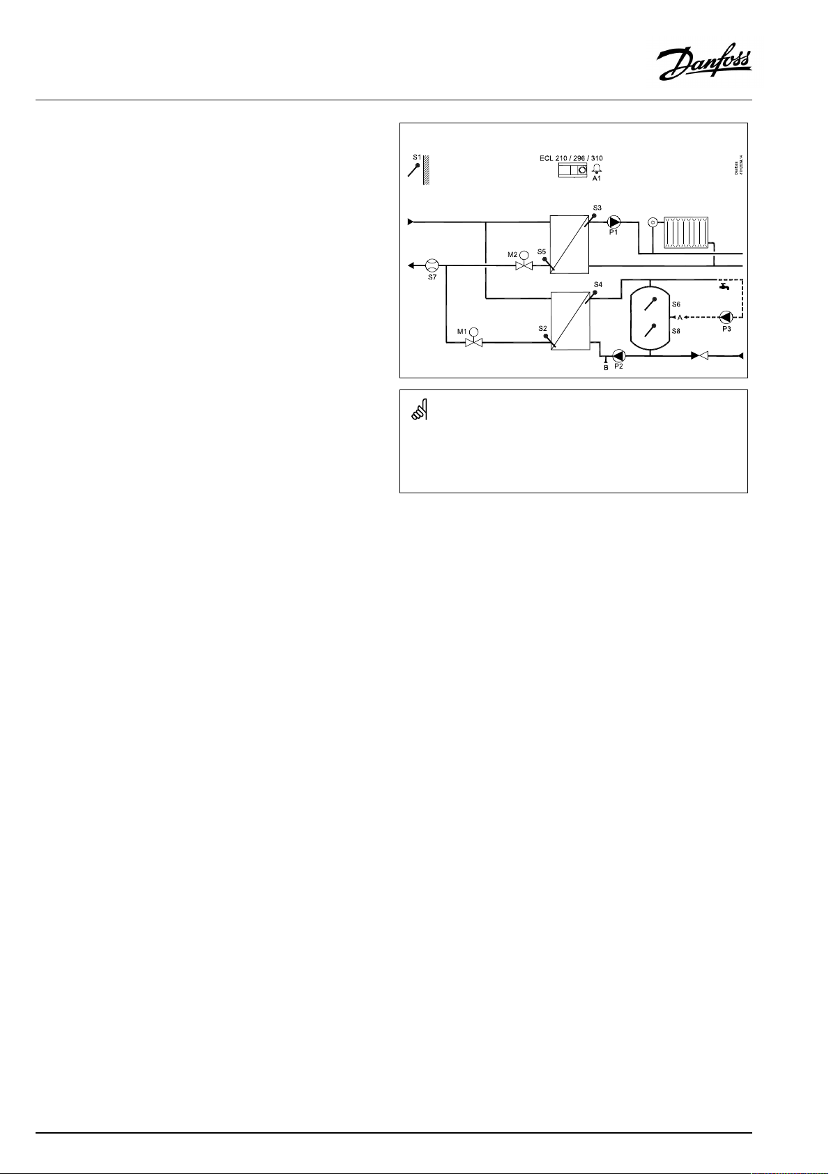
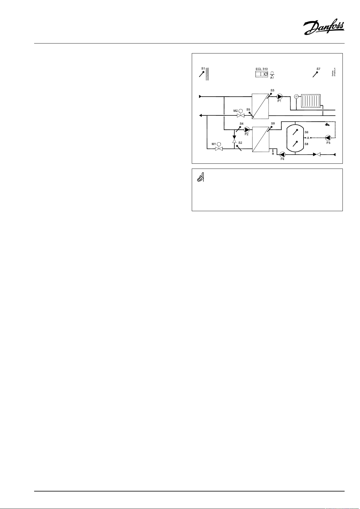
TypicalA247.2application,examplea:
Theshowndiagramisafundamentalandsimplifiedexampleanddoes
notcontainallcomponentsthatarenecessaryinasystem.
AllnamedcomponentsareconnectedtotheECLComfortcontroller.
Listofcomponents:
ECL210/310
S1
ElectroniccontrollerECLComfort210or310
Outdoortemperaturesensor
S2DHWreturntemperaturesensor,circuit2
S3
S4
Flowtemperaturesensor,circuit1
DHWflowtemperaturesensor,circuit2
S5Returntemperaturesensor,circuit1
S6
S7
S8
P1
P2
P3
P4
M1
DHWtanktemperaturesensor,upper
Flow/energymeter(pulsesignal)
DHWtanktemperaturesensor,lower
Circulationpump,heating,circuit1
DHWheatingpump,circuit2
Circulationpump,DHW,circuit2
DHWchargingpump,circuit2
Motorizedcontrolvalve(3-pointcontrolled),
circuit2
Alternative:Thermoactuator(DanfosstypeABV)
M2
Motorizedcontrolvalve(3-pointcontrolled),
circuit1
Alternative:Thermoactuator(DanfosstypeABV)
A/B
Internal/externalconnectionsforDHWcirculation
10|©Danfoss|2021.12
AQ192386469094en-010802
Page 11
OperatingGuideECLComfort210/296/310,applicationA247/A347
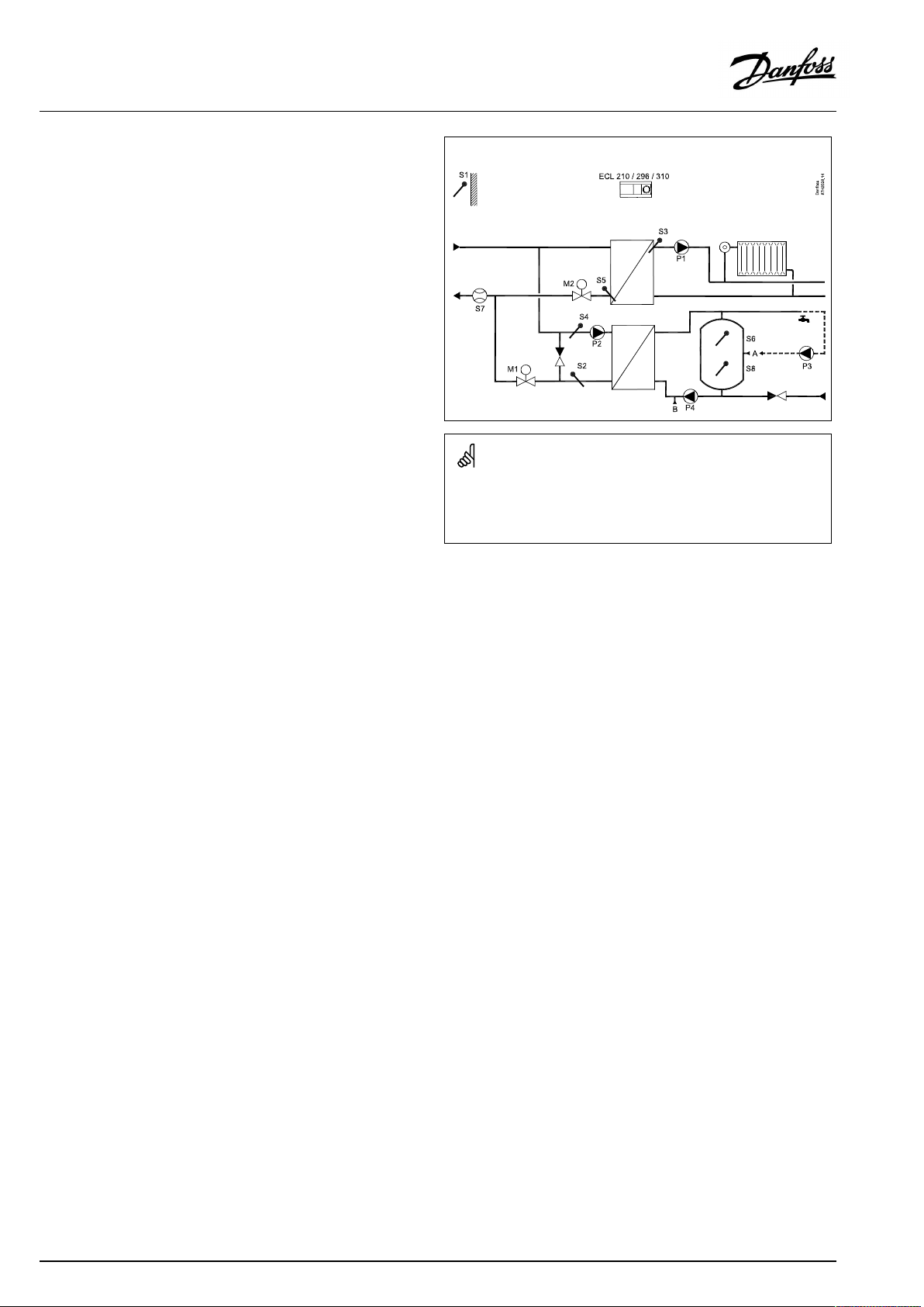
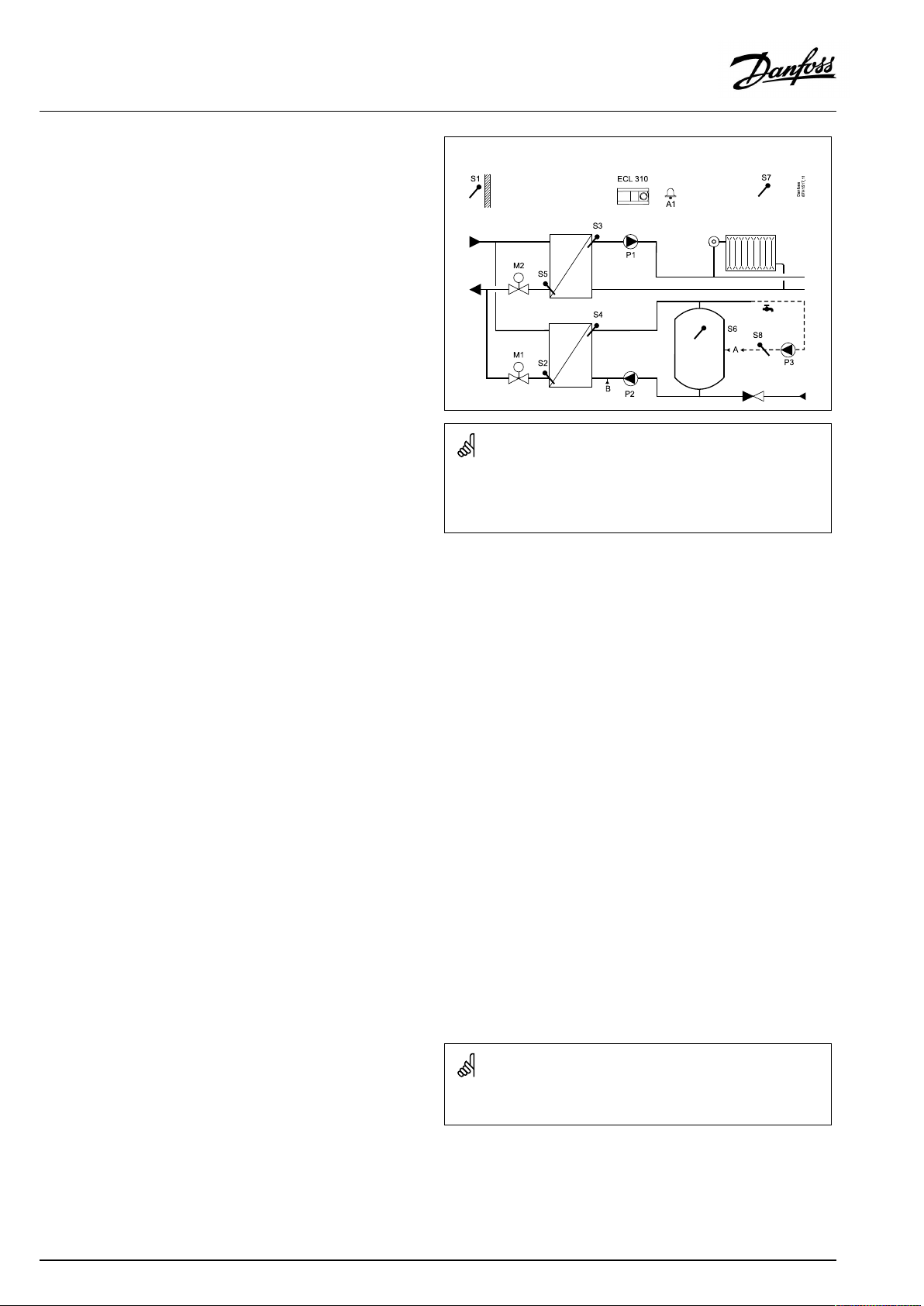
TypicalA247.3application,examplea:
Theshowndiagramisafundamentalandsimplifiedexampleanddoes
notcontainallcomponentsthatarenecessaryinasystem.
AllnamedcomponentsareconnectedtotheECLComfortcontroller.
Listofcomponents:
ECL210/310
S1
ElectroniccontrollerECLComfort210or310
Outdoortemperaturesensor
S2DHWreturntemperaturesensor,circuit2
S3
S4
Flowtemperaturesensor,circuit1
DHWheatingtemperaturesensor,circuit2
S5Returntemperaturesensor,circuit1
S6
S7
S8
P1
P2
P3
P4
M1
DHWtanktemperaturesensor,upper
DHWchargingtemperaturesensor,circuit2
DHWtanktemperaturesensor,lower
Circulationpump,heating,circuit1
DHWheatingpump,circuit2
Circulationpump,DHW,circuit2
DHWchargingpump,circuit2
Motorizedcontrolvalve(3-pointcontrolled),
circuit2
Alternative:Thermoactuator(DanfosstypeABV)
M2
Motorizedcontrolvalve(3-pointcontrolled),
circuit1
Alternative:Thermoactuator(DanfosstypeABV)
A/B
Internal/externalconnectionsforDHWcirculation
AQ192386469094en-010802
©Danfoss|2021.12|11
Page 12
OperatingGuideECLComfort210/296/310,applicationA247/A347
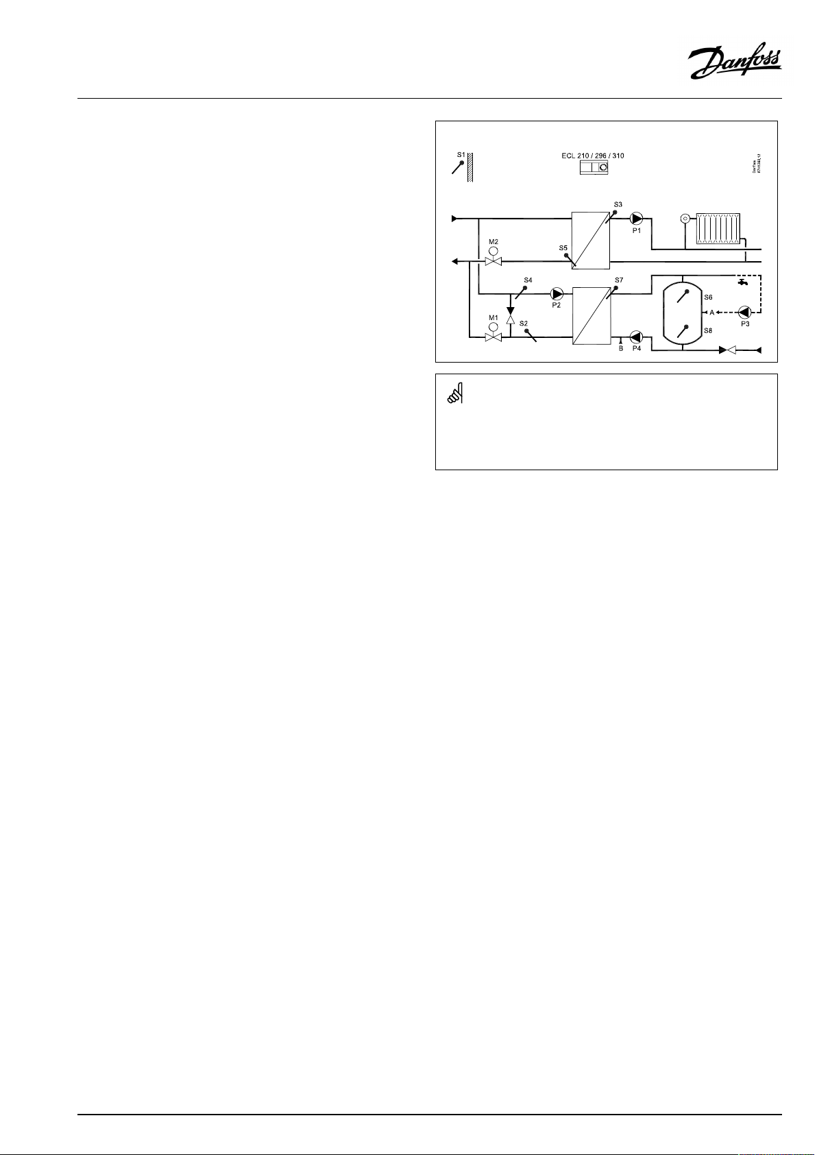
TypicalA347.1application,examplea:
Theshowndiagramisafundamentalandsimplifiedexampleanddoes
notcontainallcomponentsthatarenecessaryinasystem.
AllnamedcomponentsareconnectedtotheECLComfortcontroller.
Listofcomponents:
ECL310
S1
ElectroniccontrollerECLComfort310
Outdoortemperaturesensor
S2DHWreturntemperaturesensor,circuit2
S3
S4
Flowtemperaturesensor,circuit1
DHWflowtemperaturesensor,circuit2
S5Returntemperaturesensor,circuit1
S6
DHWtanktemperaturesensor,upper
S7Roomtemperaturesensor,circuit1
S8
S10
DHWtanktemperaturesensor,lower
Externalvoltage(0–10V)forexternalsettingof
desiredflowtemperature,circuit1
P1
P2
P3
M1
Circulationpump,heating,circuit1
Chargingpump,DHW,circuit2
Circulationpump,DHW,circuit2
Motorizedcontrolvalve(3-pointcontrolled),circuit2
Alternative:Thermoactuator(DanfosstypeABV)
M2
Motorizedcontrolvalve(3-pointcontrolled),circuit1
Alternative:Thermoactuator(DanfosstypeABV)
A1
A/B
Alarm
Internal/externalconnectionsforDHWcirculation
12|©Danfoss|2021.12
AQ192386469094en-010802
Page 13
OperatingGuideECLComfort210/296/310,applicationA247/A347
TypicalA347.2application,examplea:
Theshowndiagramisafundamentalandsimplifiedexampleanddoes
notcontainallcomponentsthatarenecessaryinasystem.
AllnamedcomponentsareconnectedtotheECLComfortcontroller.
Listofcomponents:
ECL310
S1
ElectroniccontrollerECLComfort310
Outdoortemperaturesensor
S2DHWreturntemperaturesensor,circuit2
S3
S4
Flowtemperaturesensor,circuit1
DHWheatingtemperaturesensor,circuit2
S5Returntemperaturesensor,circuit1
S6
DHWtanktemperaturesensor,upper
S7Roomtemperaturesensor,circuit1
S8
S9
S10
DHWtanktemperaturesensor,lower
DHWchargingtemperaturesensor,circuit2
Externalvoltage(0–10V)forexternalsettingof
desiredflowtemperature,circuit1
P1
P2
P3
M1
Circulationpump,heating,circuit1
Chargingpump,DHW,circuit2
Circulationpump,DHW,circuit2
Motorizedcontrolvalve(3-pointcontrolled),circuit2
Alternative:Thermoactuator(DanfosstypeABV)
M2
Motorizedcontrolvalve(3-pointcontrolled),circuit1
Alternative:Thermoactuator(DanfosstypeABV)
A1
A/B
Alarm
Internal/externalconnectionsforDHWcirculation
AQ192386469094en-010802
©Danfoss|2021.12|13
Page 14
OperatingGuideECLComfort210/296/310,applicationA247/A347
TypicalA347.3application,examplea:
Theshowndiagramisafundamentalandsimplifiedexampleanddoes
notcontainallcomponentsthatarenecessaryinasystem.
AllnamedcomponentsareconnectedtotheECLComfortcontroller.
Listofcomponents:
ECL310
S1
ElectroniccontrollerECLComfort310
Outdoortemperaturesensor
S2DHWreturntemperaturesensor,circuit2
S3
S4
Flowtemperaturesensor,circuit1
DHWchargingtemperaturesensor,circuit2
S5Returntemperaturesensor,circuit1
S6
DHWtanktemperaturesensor,upper
S7Roomtemperaturesensor,circuit1
S8
S10
DHWcirculationreturntemperaturesensor
Externalvoltage(0–10V)forexternalsettingof
desiredflowtemperature,circuit1
P1
P2
P3
M1
Circulationpump,heating,circuit1
Chargingpump,DHW,circuit2
Circulationpump,DHW,circuit2
Motorizedcontrolvalve(3-pointcontrolled),circuit2
Alternative:Thermoactuator(DanfosstypeABV)
M2
Motorizedcontrolvalve(3-pointcontrolled),circuit1
Alternative:Thermoactuator(DanfosstypeABV)
A1
A/B
Alarm
Internal/externalconnectionsforDHWcirculation
14|©Danfoss|2021.12
Thecontrollerispre-programmedwithfactorysettingsthatareshown
inthe‘ParameterIDoverview’appendix.
AQ192386469094en-010802
Page 15
OperatingGuideECLComfort210/296/310,applicationA247/A347
2.2Identifyingthesystemtype
Sketchyourapplication
TheECLComfortcontrollerseriesisdesignedforawiderange
ofheating,domestichot-water(DHW)andcoolingsystemswith
differentconfigurationsandcapacities.Ifyoursystemdiffers
fromthediagramsshownhere,youmaywanttomakeasketch
ofthesystemabouttobeinstalled.Thismakesiteasiertouse
theOperatingGuide,whichwillguideyoustep-by-stepfrom
installationtofinaladjustmentsbeforetheend-usertakesover.
TheECLComfortcontrollerisauniversalcontrollerthatcanbe
usedforvarioussystems.Basedontheshownstandardsystems,
itispossibletoconfigureadditionalsystems.Inthischapteryou
findthemostfrequentlyusedsystems.Ifyoursystemisnotquite
asshownbelow,findthediagramwhichhasthebestresemblance
withyoursystemandmakeyourowncombinations.
SeetheInstallationGuide(deliveredwiththeapplicationkey)for
applicationtypes/sub-types.
Thecirculationpump(s)inheatingcircuit(s)canbeplacedintheflow
aswellasthereturn.Placethepumpaccordingtothemanufacturer’s
specification.
AQ192386469094en-010802
©Danfoss|2021.12|15
Page 16
OperatingGuideECLComfort210/296/310,applicationA247/A347
Adviceforsettings:
Factorysettingsinthesubtypeswillrunthemostapplication
examples.Someoftheapplicationexamplesneedchangeof
dedicatedsettings.
Seethedocumentationforapplicationsandsubtypes,delivered
withtheapplicationkey.
A247.1,ex.a
A347.1,ex.a
DHWcirculationpipecanbeconnectedtotheDHWtankat'A'
forinternalcirculationortotheheat-exchangerat'B'forexternal
circulation.
Issue:
DHWcircuit(2):
InternalDHWcirculation
DHWcircuit(2):
ExternalDHWcirculation
A247.1,ex.b
A347.1,ex.b
Nospecialsettingsrequired.
A247.1,ex.c
A347.1,ex.c
Circuit2mustbeabletoreceivetheheatdemandfromcircuit1.
Issue:
Heatingcircuit(1):
Heatdemand
DHWcircuit(2):
Heatdemand
Navigation:
MENU\Settings\Application:'Cont.Tcontrol'
MENU\Settings\Application:'Cont.Tcontrol'
Navigation:
MENU\Settings\Application:'Demandoffset'
MENU\Settings\Application:'Demandoffset'
IDno.:
12054
12054
IDno.:
11017
12017
Recommended
setting:
OFF
ON
Recommended
setting:
OFF
3K*
*Thisvalueisaddedtotheheatdemandvaluefromcircuit1.
16|©Danfoss|2021.12
AQ192386469094en-010802
Page 17
OperatingGuideECLComfort210/296/310,applicationA247/A347
Adviceforsettings:
A247.2,ex.a
A347.2,ex.a
DHWcirculationpipecanbeconnectedtotheDHWtankat'A'
forinternalcirculationortotheheat-exchangerat'B'forexternal
circulation.
Issue:
DHWcircuit(2):
InternalDHWcirculation
DHWcircuit(2):
ExternalDHWcirculation
A247.2,ex.b
A347.2,ex.b
Circuit1mustbeabletoreceivetheheatdemandfromcircuit2.
Issue:
Heatingcircuit(1):
Heatdemand
DHWcircuit(2):
Heatdemand
*Thisvalueisaddedtotheheatdemandvaluefromcircuit2.
DHWcirculationpipecanbeconnectedtotheDHWtankat'A'
forinternalcirculationortotheheat-exchangerat'B'forexternal
circulation.
Navigation:
MENU\Settings\Application:'Cont.Tcontrol'
MENU\Settings\Application:'Cont.Tcontrol'
Navigation:
MENU\Settings\Application:'Demandoffset'
MENU\Settings\Application:'Demandoffset'
IDno.:
12054
12054
IDno.:
11017
12017
Recommended
setting:
OFF
ON
Recommended
setting:
3K*
OFF
Issue:
DHWcircuit(2):
InternalDHWcirculation
DHWcircuit(2):
ExternalDHWcirculation
Navigation:
MENU\Settings\Application:'Cont.Tcontrol'
MENU\Settings\Application:'Cont.Tcontrol'
IDno.:
12054
12054
Recommended
setting:
OFF
ON
AQ192386469094en-010802
©Danfoss|2021.12|17
Page 18

OperatingGuideECLComfort210/296/310,applicationA247/A347
Adviceforsettings:
A247.2,ex.c
A347.2,ex.c
Circuit2mustbeabletoreceivetheheatdemandfromcircuit1.
Issue:
Heatingcircuit(1):
Heatdemand
DHWcircuit(2):
Heatdemand
*Thisvalueisaddedtotheheatdemandvaluefromcircuit1.
DHWcirculationpipecanbeconnectedtotheDHWtankat'A'
forinternalcirculationortotheheat-exchangerat'B'forexternal
circulation.
Issue:
DHWcircuit(2):
InternalDHWcirculation
DHWcircuit(2):
ExternalDHWcirculation
Navigation:
MENU\Settings\Application:'Demandoffset'
MENU\Settings\Application:'Demandoffset'
Navigation:
MENU\Settings\Application:'Cont.Tcontrol'
MENU\Settings\Application:'Cont.Tcontrol'
IDno.:
11017
12017
IDno.:
12054
12054
Recommended
setting:
OFF
3K*
Recommended
setting:
OFF
ON
18|©Danfoss|2021.12
AQ192386469094en-010802
Page 19
OperatingGuideECLComfort210/296/310,applicationA247/A347
Adviceforsettings:
A247.3,ex.a
DHWcirculationpipecanbeconnectedtotheDHWtankat'A'
forinternalcirculationortotheheat-exchangerat'B'forexternal
circulation.
Issue:
DHWcircuit(2):
InternalDHWcirculation
DHWcircuit(2):
ExternalDHWcirculation
A247.3,ex.b
Circuit1mustbeabletoreceivetheheatdemandfromcircuit2.
Issue:
Heatingcircuit(1):
Heatdemand
DHWcircuit(2):
Heatdemand
*Thisvalueisaddedtotheheatdemandvaluefromcircuit2.
DHWcirculationpipecanbeconnectedtotheDHWtankat'A'
forinternalcirculationortotheheat-exchangerat'B'forexternal
circulation.
Navigation:
MENU\Settings\Application:'Cont.Tcontrol'
MENU\Settings\Application:'Cont.Tcontrol'
Navigation:
MENU\Settings\Application:'Demandoffset'
MENU\Settings\Application:'Demandoffset'
IDno.:
12054
12054
IDno.:
11017
12017
Recommended
setting:
OFF
ON
Recommended
setting:
3K*
OFF
Issue:
DHWcircuit(2):
InternalDHWcirculation
DHWcircuit(2):
ExternalDHWcirculation
Navigation:
MENU\Settings\Application:'Cont.Tcontrol'
MENU\Settings\Application:'Cont.Tcontrol'
IDno.:
12054
12054
Recommended
setting:
OFF
ON
AQ192386469094en-010802
©Danfoss|2021.12|19
Page 20

OperatingGuideECLComfort210/296/310,applicationA247/A347
Adviceforsettings:
A247.3,ex.c
Circuit2mustbeabletoreceivetheheatdemandfromcircuit1.
Issue:
Heatingcircuit(1):
Heatdemand
DHWcircuit(2):
Heatdemand
*Thisvalueisaddedtotheheatdemandvaluefromcircuit1.
DHWcirculationpipecanbeconnectedtotheDHWtankat'A'
forinternalcirculationortotheheat-exchangerat'B'forexternal
circulation.
Issue:
DHWcircuit(2):
InternalDHWcirculation
DHWcircuit(2):
ExternalDHWcirculation
A347.3,ex.a
Nospecialsettingsrequired.
Navigation:
MENU\Settings\Application:'Demandoffset'
MENU\Settings\Application:'Demandoffset'
Navigation:
MENU\Settings\Application:'Cont.Tcontrol'
MENU\Settings\Application:'Cont.Tcontrol'
IDno.:
11017
12017
IDno.:
12054
12054
Recommended
setting:
OFF
3K*
Recommended
setting:
OFF
ON
20|©Danfoss|2021.12
AQ192386469094en-010802
Page 21
OperatingGuideECLComfort210/296/310,applicationA247/A347
2.3Mounting
2.3.1MountingtheECLComfortcontroller
SeetheInstallationGuidewhichisdeliveredtogetherwiththe
ECLComfortcontroller.
Foreasyaccess,youshouldmounttheECLComfortcontrollernear
thesystem.
ECLComfort210/296/310canbemounted
•onawall
•onaDINrail(35mm)
ECLComfort296canbemounted
•inapanelcut-out
ECLComfort210canbemountedinanECLComfort310basepart
(forfutureupgrade).
Screws,PGcableglandsandrawlplugsarenotsupplied.
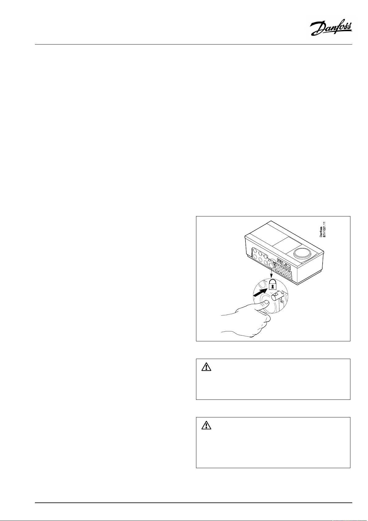
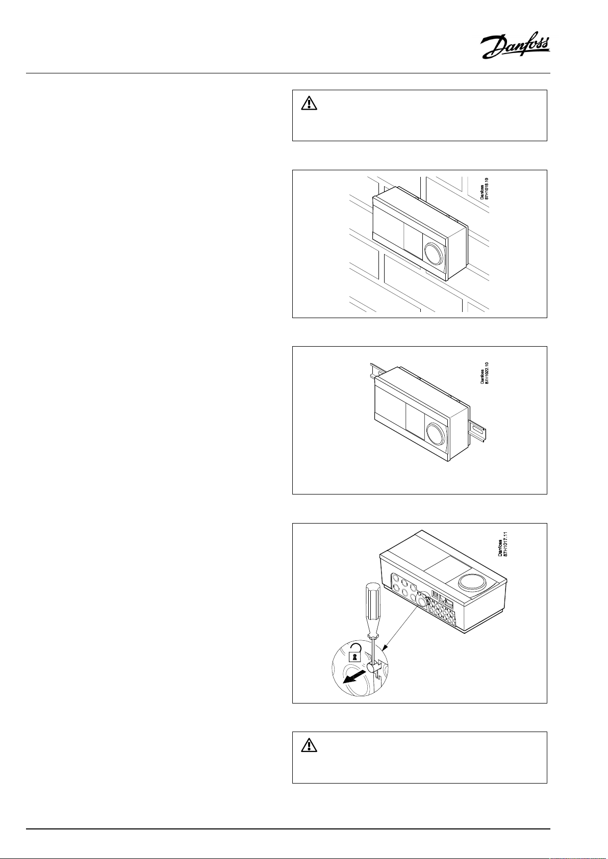
LockingtheECLComfort210/310controller
InordertofastentheECLComfortcontrollertoitsbasepart,secure
thecontrollerwiththelockingpin.
Topreventinjuriestopersonsorthecontroller,thecontrollerhasto
besecurelylockedintothebase.Forthispurpose,pressthelocking
pinintothebaseuntilaclickisheardandthecontrollernolonger
canberemovedfromthebase.
Ifthecontrollerisnotsecurelylockedintothebasepart,thereisarisk
thatthecontrollerduringoperationcanunlockfromthebaseandthe
basewithterminals(andalsothe230Va.c.connections)areexposed.
Topreventinjuriestopersons,alwaysmakesurethatthecontroller
issecurelylockedintoitsbase.Ifthisisnotthecase,thecontroller
shouldnotbeoperated!
AQ192386469094en-010802
©Danfoss|2021.12|21
Page 22
OperatingGuideECLComfort210/296/310,applicationA247/A347
Mountingonawall
Mountthebasepartonawallwithasmoothsurface.Establishthe
electricalconnectionsandpositionthecontrollerinthebasepart.
Securethecontrollerwiththelockingpin.
MountingonaDINrail(35mm)
MountthebasepartonaDINrail.Establishtheelectrical
connectionsandpositionthecontrollerinthebasepart.Secure
thecontrollerwiththelockingpin.
Theeasywaytolockthecontrollertoitsbaseorunlockitistousea
screwdriveraslever.
DismountingtheECLComfortcontroller
Inordertoremovethecontrollerfromthebasepart,pulloutthe
lockingpinbymeansofascrewdriver.Thecontrollercannowbe
removedfromthebasepart.
Theeasywaytolockthecontrollertoitsbaseorunlockitistousea
screwdriveraslever.
22|©Danfoss|2021.12
AQ192386469094en-010802
Page 23
OperatingGuideECLComfort210/296/310,applicationA247/A347
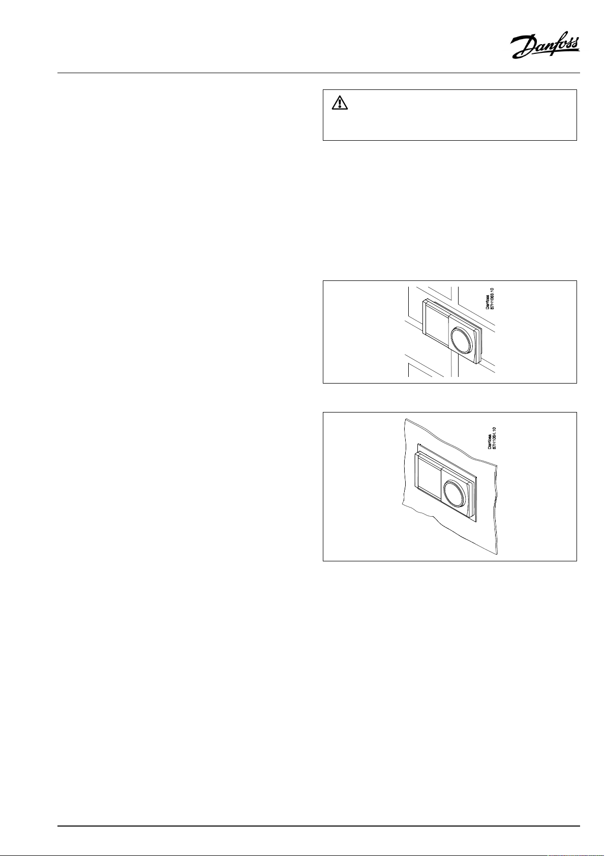
2.3.2MountingtheRemoteControlUnitsECA30/31
Selectoneofthefollowingmethods:
•Mountingonawall,ECA30/31
•Mountinginapanel,ECA30
Screwsandrawlplugsarenotsupplied.
Mountingonawall
MountthebasepartoftheECA30/31onawallwithasmooth
surface.Establishtheelectricalconnections.PlacetheECA30/
31inthebasepart.
BeforeremovingtheECLComfortcontrollerfromthebasepart,ensure
thatthesupplyvoltageisdisconnected.
Mountinginapanel
MounttheECA30inapanelusingtheECA30framekit(ordercode
no.087H3236).Establishtheelectricalconnections.Securethe
framewiththeclamp.PlacetheECA30inthebasepart.TheECA
30canbeconnectedtoanexternalroomtemperaturesensor.
TheECA31mustnotbemountedinapanelifthehumidity
functionistobeused.
AQ192386469094en-010802
©Danfoss|2021.12|23
Page 24
OperatingGuideECLComfort210/296/310,applicationA247/A347
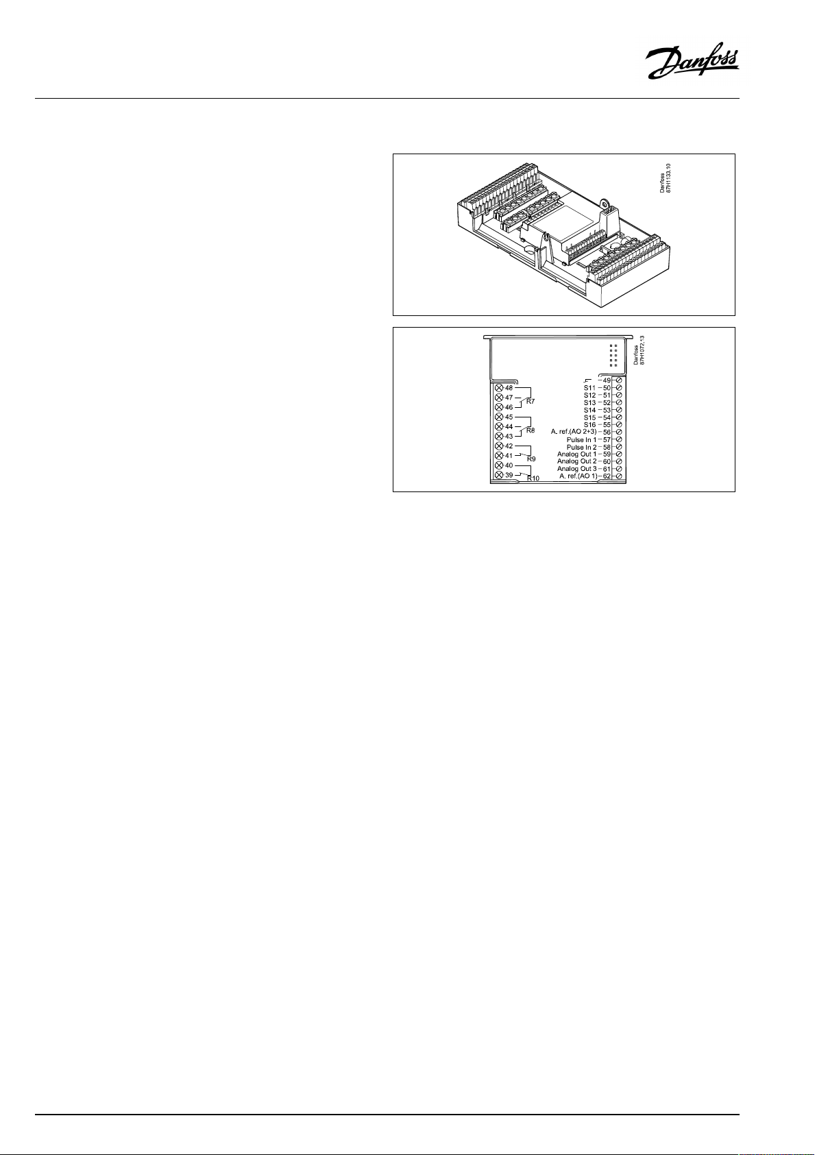
2.3.3MountingtheinternalI/OmoduleECA32
MountingoftheinternalI/OmoduleECA32
TheECA32module(ordercodeno.087H3202)mustbeinserted
intotheECLComfort310/310Bbasepartforadditionalinputand
outputsignalsinrelevantapplications.
TheconnectionbetweentheECLComfort310/310BandECA32
isa10-pole(2x5)connector.Theconnectionisautomatically
establishedwhentheECLComfort310/310Bisplacedonthe
basepart.
24|©Danfoss|2021.12
AQ192386469094en-010802
Page 25
OperatingGuideECLComfort210/296/310,applicationA247/A347
2.4Placingthetemperaturesensors
2.4.1Placingthetemperaturesensors
Itisimportantthatthesensorsaremountedinthecorrectposition
inyoursystem.
Thetemperaturesensormentionedbelowaresensorsusedforthe
ECLComfort210/296/310serieswhichnotallwillbeneeded
foryourapplication!
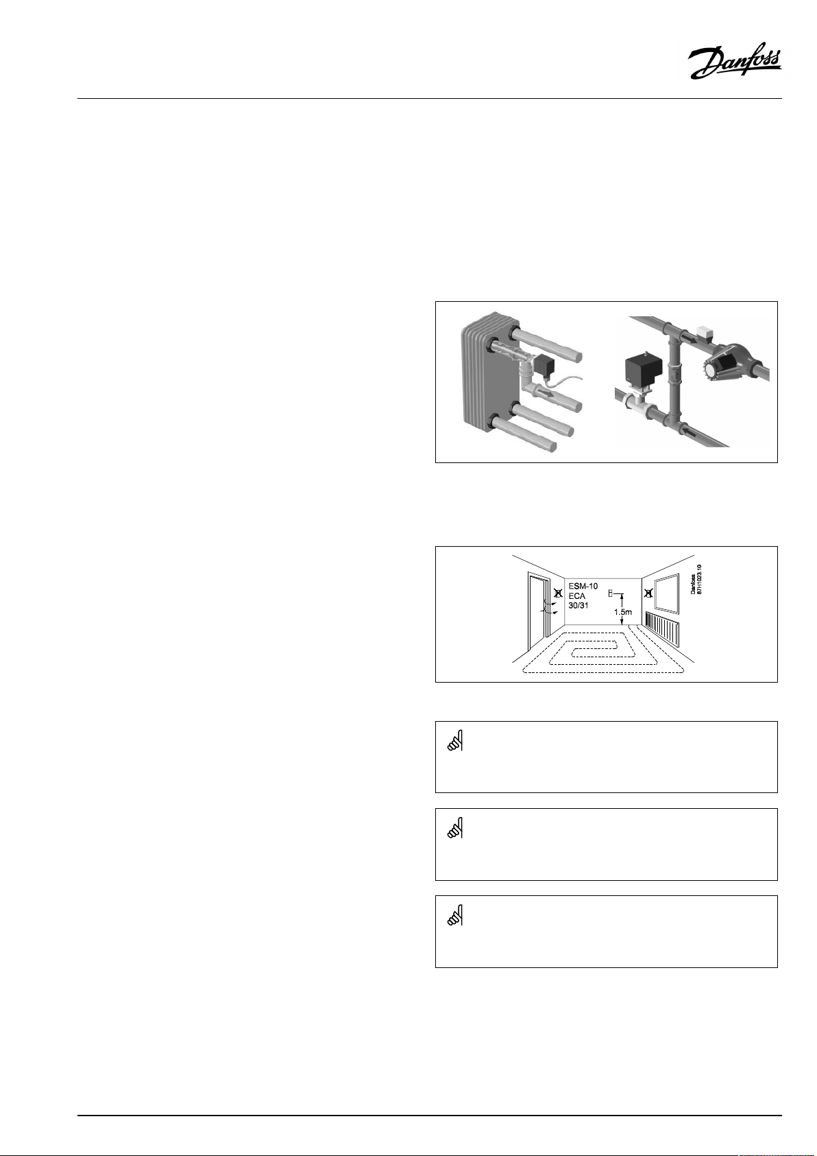
Outdoortemperaturesensor(ESMT)
Theoutdoorsensorshouldbemountedonthatsideofthebuilding
whereitislesslikelytobeexposedtodirectsunshine.Itshouldnot
beplacedclosetodoors,windowsorairoutlets.
Flowtemperaturesensor(ESMU,ESM-11orESMC)
Placethesensormax.15cmfromthemixingpoint.Insystems
withheatexchanger,DanfossrecommendsthattheESMU-typeto
beinsertedintotheexchangerflowoutlet.
Makesurethatthesurfaceofthepipeiscleanandevenwhere
thesensorismounted.
Returntemperaturesensor(ESMU,ESM-11orESMC)
Thereturntemperaturesensorshouldalwaysbeplacedsothatit
measuresarepresentativereturntemperature.
Roomtemperaturesensor
(ESM-10,ECA30/31RemoteControlUnit)
Placetheroomsensorintheroomwherethetemperatureistobe
controlled.Donotplaceitonoutsidewallsorclosetoradiators,
windowsordoors.
Boilertemperaturesensor(ESMU,ESM-11orESMC)
Placethesensoraccordingtotheboilermanufacturer’s
specification.
Airducttemperaturesensor(ESMB-12orESMUtypes)
Placethesensorsothatitmeasuresarepresentativetemperature.
DHWtemperaturesensor(ESMUorESMB-12)
PlacetheDHWtemperaturesensoraccordingtothemanufacturer’s
specification.
Slabtemperaturesensor(ESMB-12)
Placethesensorinaprotectiontubeintheslab.
ESM-11:Donotmovethesensorafterithasbeenfastenedinorderto
avoiddamagetothesensorelement.
ESM-11,ESMCandESMB-12:Useheatconductingpasteforquick
measurementofthetemperature.
ESMUandESMB-12:Usingasensorpockettoprotectthesensorwill,
however,resultinaslowertemperaturemeasurement.
AQ192386469094en-010802
©Danfoss|2021.12|25
Page 26
OperatingGuideECLComfort210/296/310,applicationA247/A347
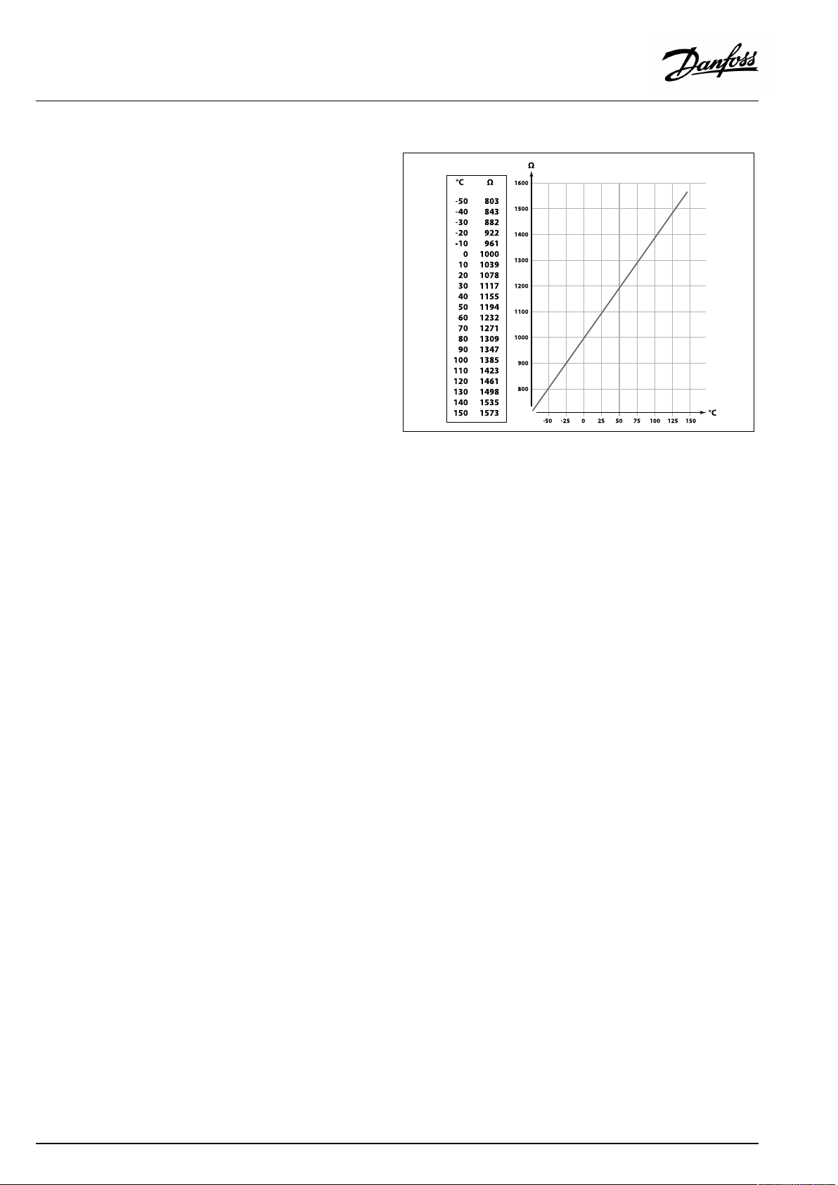
Pt1000temperaturesensor(IEC751B,1000Ω/0°C)
Relationshipbetweentemperatureandohmicvalue:
26|©Danfoss|2021.12
AQ192386469094en-010802
Page 27
OperatingGuideECLComfort210/296/310,applicationA247/A347
2.5Electricalconnections
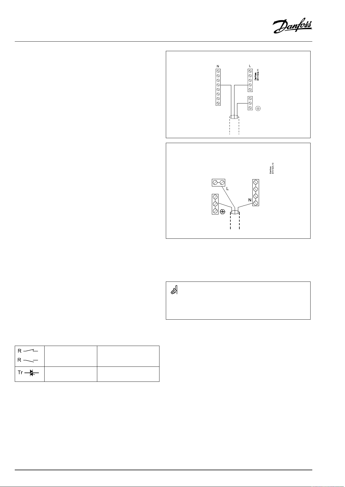
2.5.1Electricalconnections230Va.c.
Warning
ElectricconductorsonPCB(PrintedCircuitBoard)forsupplyvoltage,
relaycontactsandtriacoutputsdonothavemutualsafetydistanceof
minimum6mm.Theoutputsarenotallowedtobeusedasgalvanic
separated(voltfree)outputs.
Ifagalvanicseparatedoutputisneeded,anauxiliaryrelayis
recommended.
24Voltcontrolledunits,forexampleactuators,aretobecontrolledby
meansofECLComfort310,24Voltversion.
SafetyNote
Necessaryassembly,start-up,andmaintenanceworkmustbe
performedbyqualifiedandauthorizedpersonnelonly.
Locallegislationsmustberespected.Thiscomprisesalsocablesize
andisolation(reinforcedtype).
AfusefortheECLComfortinstallationismax.10Atypically.
TheambienttemperaturerangefortheECLComfortinoperationis
0-55°C.Exceedingthistemperaturerangecanresultinmalfunctions.
Installationmustbeavoidedifthereisariskforcondensation(dew).
AQ192386469094en-010802
©Danfoss|2021.12|27
Page 28
OperatingGuideECLComfort210/296/310,applicationA247/A347
Thecommongroundterminalisusedforconnectionofrelevant
components(pumps,motorizedcontrolvalves).
ECL210/310
ECL296
SeealsotheInstallationGuide(deliveredwiththeapplicationkey)
forapplicationspecificconnections.
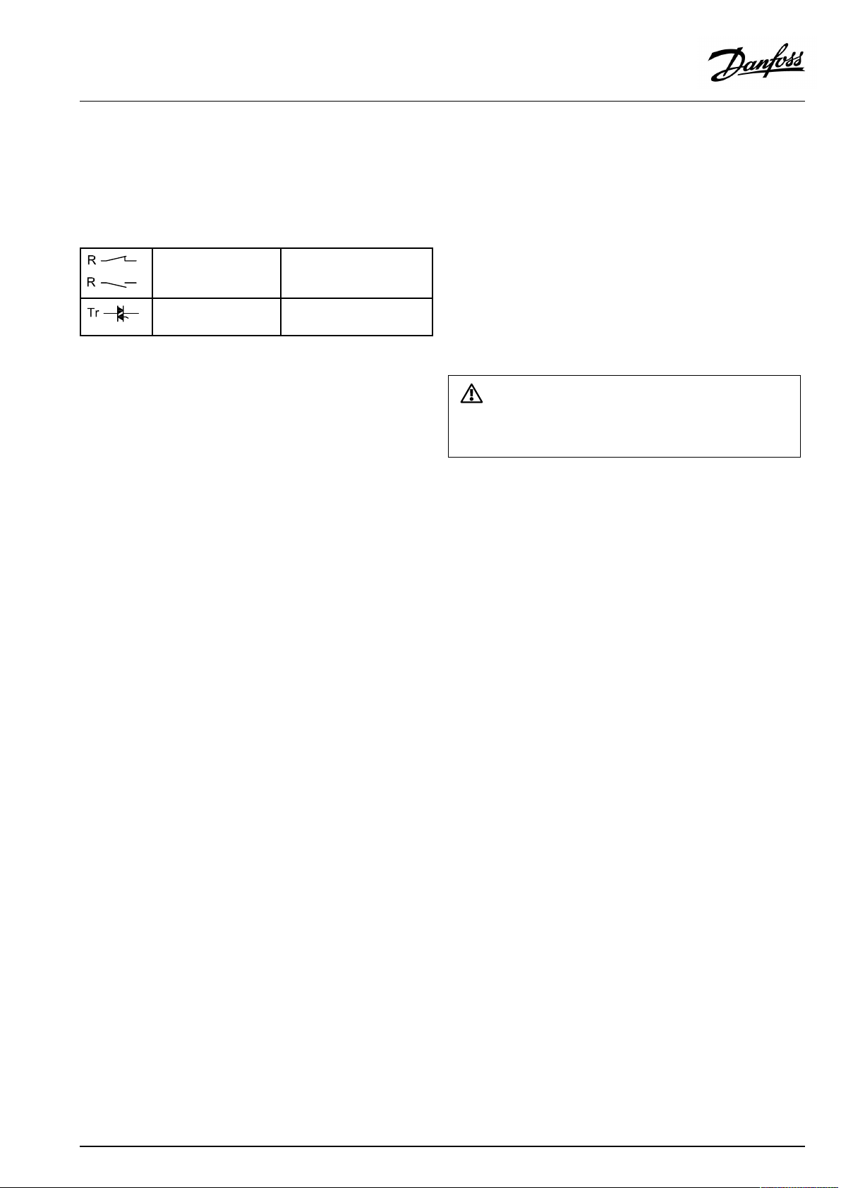
Maximumloadratings:
Relayterminals
4(2)A/230Va.c.
(4Aforohmicload,2Afor
inductiveload)
Triac(=electronic
0,2A/230Va.c.
relay)terminals
Wirecrosssection:0.5-1.5mm²
Incorrectconnectioncandamagetheelectronicoutputs.
Max.2x1.5mm²wirescanbeinsertedintoeachscrewterminal.
28|©Danfoss|2021.12
AQ192386469094en-010802
Page 29
OperatingGuideECLComfort210/296/310,applicationA247/A347
2.5.2Electricalconnections24Va.c.
SeealsotheInstallationGuide(deliveredwiththeapplicationkey)
forapplicationspecificconnections.
Maximumloadratings:
Relayterminals
Triac(=electronic
relay)terminals
4(2)A/24Va.c.
(4Aforohmicload,2Afor
inductiveload)
1A/24Va.c.
Donotconnect230Va.c.poweredcomponentstoa24Va.c.power
suppliedcontrollerdirectly.Useauxilliaryrelays(K)toseparate230
Va.c.from24Va.c.
AQ192386469094en-010802
©Danfoss|2021.12|29
Page 30
OperatingGuideECLComfort210/296/310,applicationA247/A347
2.5.3Electricalconnections,safetythermostats,230Va.c.or24Va.c.
SeealsotheInstallationGuide(deliveredwiththeapplicationkey)
forapplicationspecificconnections.
Theconnectiondiagramsshowvarioussolutions/examples:
Safetythermostat,1–stepclosing:
Motorizedcontrolvalvewithoutsafetyfunction
Safetythermostat,1–stepclosing:
Motorizedcontrolvalvewithsafetyfunction
Safetythermostat,2–stepclosing:
Motorizedcontrolvalvewithsafetyfunction
WhenSTisactivatedbyahightemperature,thesafetycircuitinthe
motorizedcontrolvalveclosesthevalveimmediately.
WhenST1isactivatedbyahightemperature(theTRtemperature),the
motorizedcontrolvalveisclosedgradually.Atahighertemperature
(theSTtemperature),thesafetycircuitinthemotorizedcontrolvalve
closesthevalveimmediately.
30|©Danfoss|2021.12
AQ192386469094en-010802
Page 31

OperatingGuideECLComfort210/296/310,applicationA247/A347
2.5.4Electricalconnections,Pt1000temperaturesensorsandsignals
SeetheInstallationGuide(deliveredwiththeapplicationkey)for
sensorandinputconnections.
A247/A347:
Sensor
S1
S2DHWreturntemperature
S3
S4
S5Returntemperaturesensor
S6
S7
S8
S9
S10
Description
Outdoortemperature
sensor*
sensor
Flowtemperaturesensor***
(heating)
A247.1,A247.2,A347.1,
A347.3:
DHWchargingtemperature
sensor***
A247.3,A347.2:
DHWheatingtemperature
sensor***
(heating)
UpperDHWtank
temperaturesensor***
A247.1,A247.2,A247.3:
Flow/energymeter(pulse
signal)
A347.1,A347.2,A347.3:
Roomtemperaturesensor**
Alternative:ECA30/31
A247.1,A247.2,A247.3,
A347.1,A347.2:
LowerDHWtank
temperaturesensor****
A347.3:
DHWcirculationreturn
temperaturesensor
A347.2:
DHWchargingtemperature
sensor***
A347.1,A347.2,A347.3:
Voltagesignal(0-10V)for
externalcontrolofdesired
flowtemperatureincircuit1
Recommendedtype
ESMT
ESM-11/ESMB/
ESMC/ESMU
ESM-11/ESMB/
ESMC/ESMU
ESM-11/ESMB/
ESMC/ESMU
ESM-11/ESMB/
ESMC/ESMU
ESMB/
ESMU
ESM-10
ESMB/
ESMU
ESM-11/ESMB/
ESMC/ESMU
ESM-11/ESMB/
ESMC/ESMU
*
Iftheoutdoortemperaturesensorisnotconnectedorthe
cableisshort-circuited,thecontrollerassumesthatthe
outdoortemperatureis0(zero)°C.
**
Onlyforroomtemperaturesensorconnection.Theroom
temperaturesignalcanalsobeavailablefromaRemote
ControlUnit(ECA30/31).SeetheMountingGuide(delivered
withtheapplicationkey)forspecificconnections.
***
Thetemperaturesensormustalwaysbeconnectedinorderto
havethedesiredfunctionality.Ifthesensorisnotconnected
orthecableisshort-circuited,themotorizedcontrolvalve
closes(safetyfunction).
****
ThissensorisusedwhentwoDHWtanktemperaturesensors
arerequired.
AQ192386469094en-010802
©Danfoss|2021.12|31
Page 32

OperatingGuideECLComfort210/296/310,applicationA247/A347
A347.1/A347.2/A347.3:
Connectionofvoltagesignal(0–10V)forexternalcontrolof
desiredflowtemperature
Wirecrosssectionforsensorconnections:Min.0.4mm².
Totalcablelength:Max.200m(allsensorsincl.internalECL485
communicationbus).
Cablelengthsofmorethan200mmaycausenoisesensibility(EMC).
Connectionofflowmeter
SeetheInstallationGuide(deliveredwiththeapplicationkey).
32|©Danfoss|2021.12
AQ192386469094en-010802
Page 33
OperatingGuideECLComfort210/296/310,applicationA247/A347
2.5.5Electricalconnections,ECA30/31
Terminal
ECL
Terminal
ECA30/31
30
31
4
1
322
333
4
5
*
Afteranexternalroomtemperaturesensorhasbeenconnected,
Description
Twistedpair
Twistedpair
Ext.roomtemperature
sensor*
Type
(recomm.)
Cable2x
twistedpair
ESM-10
ECA30/31mustberepowered.
ThecommunicationtotheECA30/31mustbesetupintheECL
Comfortcontrollerin'ECAaddr.'
TheECA30/31mustbesetupaccordingly.
AfterapplicationsetuptheECA30/31isreadyafter2–5min.A
progressbarintheECA30/31isdisplayed.
Iftheactualapplicationcontainstwoheatingcircuits,itispossible
toconnectanECA30/31toeachcircuit.Theelectricalconnections
aredoneinparallel.
Max.2ECA30/31canbeconnectedtoanECLComfort310controller
ortoECLComfort210/296/310controllersinamaster-slavesystem.
SetupproceduresforECA30/31:Seesection‘Miscellaneous’ .
ECAinformationmessage:
‘Applicationreq.newerECA’:
Thesoftware(firmware)ofyourECAdoesnotcomplywiththe
software(firmware)ofyourECLComfortcontroller.Pleasecontact
yourDanfosssalesoffice.
Someapplicationsdonotcontainfunctionsrelatedtoactualroom
temperature.TheconnectedECA30/31willonlyfunctionasremote
control.
AQ192386469094en-010802
©Danfoss|2021.12|33
Page 34
OperatingGuideECLComfort210/296/310,applicationA247/A347
2.5.6Electricalconnections,master/slavesystems
Thecontrollercanbeusedasmasterorslaveinmaster/slave
systemsviatheinternalECL485communicationbus(2xtwisted
paircable).
TheECL485communicationbusisnotcompatiblewiththeECL
businECLComfort110,200,300and301!
Totalcablelength:Max.200m(allsensorsincl.internalECL485
communicationbus).
Cablelengthsofmorethan200mmaycausenoisesensibility(EMC).
Terminal
Description
Type
(recomm.)
30
Commonterminal
+12V*,ECL485communicationbus
31
*OnlyforECA30/31andmaster/
slavecommunication
32
B,ECL485communicationbus
33
A,ECL485communicationbus
Cable2x
twistedpair
ECL485buscable
MaximumrecommendedlengthoftheECL485busiscalculatedlike
this:
Subtract"TotallengthofallinputcablesofallECLcontrollersinthe
master-slavesystem"from200m.
Simpleexamplefortotallengthofallinputcables,3xECL:
1xECL
3xECL
3xECLReturntemp.sensor:
3xECLRoomtemp.sensor:
Total:
Outdoortemp.sensor:
Flowtemp.sensor:
15m
18m
18m
30m
81m
2.5.7Electricalconnections,communication
Electricalconnections,Modbus
ECLComfort210:Non-galvanicisolatedModbusconnections
ECLComfort296:GalvanicisolatedModbusconnections
ECLComfort310:GalvanicisolatedModbusconnections
34|©Danfoss|2021.12
MaximumrecommendedlengthoftheECL485bus:
200-81m=119m
AQ192386469094en-010802
Page 35

OperatingGuideECLComfort210/296/310,applicationA247/A347
2.5.8Electricalconnections,communication
Electricalconnections,M-bus
ECLComfort210:Notimplemented
ECLComfort296:Onboard,non-galvanicisolated.Max.cable
length50m.
ECLComfort310:Onboard,non-galvanicisolated.Max.cable
length50m.
AQ192386469094en-010802
©Danfoss|2021.12|35
Page 36

OperatingGuideECLComfort210/296/310,applicationA247/A347
2.6InsertingtheECLApplicationKey
2.6.1InsertingtheECLApplicationKey
TheECLApplicationKeycontains
•theapplicationanditssubtypes,
•currentlyavailablelanguages,
•factorysettings:e.g.schedules,desiredtemperatures,
limitationvaluesetc.Itisalwayspossibletorecoverthefactory
settings,
•memoryforusersettings:specialuser/systemsettings.
Afterhavingpowered-upthecontroller,differentsituationsmight
beexisting:
1.Thecontrollerisnewfromthefactory,theECLApplicationKey
isnotinserted.
2.Thecontrolleralreadyrunsanapplication.TheECLApplication
Keyisinserted,buttheapplicationneedstobechanged.
3.Acopyofthecontrollerssettingsisneededforconfiguring
anothercontroller.
ECLComfort210/310
ECLComfort210/310
Usersettingsare,amongothers,desiredroomtemperature,desired
DHWtemperature,schedules,heatcurve,limitationvaluesetc.
Systemsettingsare,amongothers,communicationset-up,display
brightnessetc.
36|©Danfoss|2021.12
ECLComfort296
AQ192386469094en-010802
Page 37
OperatingGuideECLComfort210/296/310,applicationA247/A347
Automaticupdateofcontrollersoftware(firmware):
Thesoftwareofthecontrollerisupdatedautomaticallywhenthekey
isinserted(asofcontrollerversion1.11(ECL210/310)andversion
1.58(ECL296)).Thefollowinganimationwillbeshownwhenthe
softwareisbeingupdated:
Progressbar
Duringupdate:
•DonotremovetheKEY
Ifthekeyisremovedbeforethehour-glassisshown,youhave
tostartafresh.
•Donotdisconnectthepower
Ifthepowerisinterruptedwhenthehour-glassisshown,the
controllerwillnotwork.
•Manualupdateofcontrollersoftware(firmware):
Seethesection"Automatic/manualupdateoffirmware"
The“Keyoverview”doesnotinform—throughECA30/31—about
thesubtypesoftheapplicationkey.
Keyinserted/notinserted,description:
ECLComfort210/310,controllerversionslowerthan1.36:
-
Takeouttheapplicationkey;for20minutes
settingscanbechanged.
-
Powerupthecontrollerwithoutthe
applicationkeyinserted;for20minutes
settingscanbechanged.
ECLComfort210/310,controllerversions1.36andup:
-
Takeouttheapplicationkey;for20minutes
settingscanbechanged.
-
Powerupthecontrollerwithoutthe
applicationkeyinserted;settingscannotbe
changed.
ECLComfort296,controllerversions1.58andup:
-
Takeouttheapplicationkey;for20minutes
settingscanbechanged.
-
Powerupthecontrollerwithoutthe
applicationkeyinserted;settingscannotbe
changed.
AQ192386469094en-010802
©Danfoss|2021.12|37
Page 38
OperatingGuideECLComfort210/296/310,applicationA247/A347
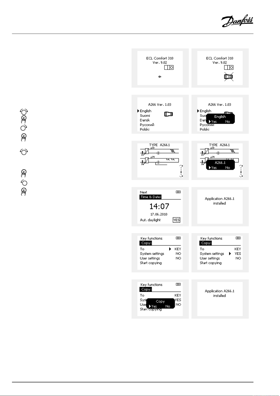
ApplicationKey:Situation1
Thecontrollerisnewfromthefactory,theECLApplicationKey
isnotinserted.
AnanimationfortheECLApplicationKeyinsertionisdisplayed.
InserttheApplicationKey.
ApplicationKeynameandVersionisindicated(example:A266
Ver.1.03).
IftheECLApplicationKeyisnotsuitableforthecontroller,a"cross"
isdisplayedovertheECLApplicationKey-symbol.
Action:Purpose:
Selectlanguage
Confirm
Selectapplication(subtype)
Somekeyshaveonlyoneapplication.
Confirmwith‘Yes’
Set'Time&Date'
Turnandpushthedialtoselectand
change'Hours' ,'Minutes','Date',
'Month'and'Year' .
Choose''Next'
Confirmwith‘Yes’
Goto‘Aut.daylight’
Choosewhether‘ Aut.daylight´*
shouldbeactiveornot
*‘Aut.daylight’istheautomaticchangeoverbetweensummer
andwintertime.
DependingonthecontentsoftheECLApplicationKey,procedure
AorBistakingplace:
A
TheECLApplicationkeycontainsfactorysettings:
Thecontrollerreads/transfersdatafromtheECLApplicationKey
toECLcontroller.
Examples:
YESorNO
Theapplicationisinstalled,andthecontrollerresetsandstartsup.
B
TheECLApplicationkeycontainschangedsystemsettings:
Pushthedialrepeatedly.
’NO’:
’YES*:
Ifthekeycontainsusersettings:
Pushthedialrepeatedly.
‘NO:
‘YES*:
*If‘YES’cannotbechosen,theECLApplicationKeydoesnot
containanyspecialsettings.
Choose‘Startcopying’andconfirmwith'Yes'.
38|©Danfoss|2021.12
OnlyfactorysettingsfromtheECLApplicationKeywill
becopiedtothecontroller.
Specialsystemsettings(differingfromthefactory
settings)willbecopiedtothecontroller.
OnlyfactorysettingsfromtheECLApplicationKeywill
becopiedtothecontroller.
Specialusersettings(differingfromthefactorysettings)
willbecopiedtothecontroller.
AQ192386469094en-010802
Page 39

OperatingGuideECLComfort210/296/310,applicationA247/A347
(Example):
The"i"intheupperrightcornerindicatesthat-besidesthefactory
settings-thesubtypealsocontainsspecialuser/systemssettings.
ApplicationKey:Situation2
Thecontrolleralreadyrunsanapplication.TheECLApplication
Keyisinserted,buttheapplicationneedstobechanged.
TochangetoanotherapplicationontheECLApplicationKey,the
currentapplicationinthecontrollermustbeerased(deleted).
BeawarethattheApplicationKeymustbeinserted.
Action:Purpose:
Choose‘MENU’inanycircuit
Confirm
Choosethecircuitselectoratthetop
rightcornerinthedisplay
Confirm
Choose‘Commoncontrollersettings’
Confirm
Choose‘Keyfunctions’
Confirm
Choose‘Eraseapplication’
Confirmwith‘Yes’
Thecontrollerresetsandisreadytobeconfigured.
Followtheproceduredescribedinsituation1.
Examples:
AQ192386469094en-010802
©Danfoss|2021.12|39
Page 40
OperatingGuideECLComfort210/296/310,applicationA247/A347
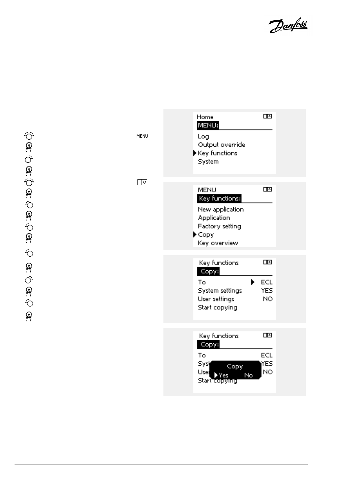
ApplicationKey:Situation3
Acopyofthecontrollerssettingsisneededforconfiguring
anothercontroller.
Thisfunctionisused
•forsaving(backup)ofspecialuserandsystemsettings
•whenanotherECLComfortcontrollerofthesametype(210,
296or310)mustbeconfiguredwiththesameapplicationbut
user/systemsettingsdifferfromthefactorysettings.
HowtocopytoanotherECLComfortcontroller:
Action:Purpose:
Choose‘MENU’
Confirm
Choosethecircuitselectoratthetop
rightcornerinthedisplay
Confirm
Choose'Commoncontrollersettings'
Confirm
Goto‘Keyfunctions’
Confirm
Choose‘Copy’
Confirm
Choose‘To’ .
‘ECL’or‘KEY’willbeindicated.Choose
’ECL’orKEY’
Pushthedialrepeatedlytochoose
copydirection
Choose‘Systemsettings’or‘User
settings’
Pushthedialrepeatedlytochoose
‘Yes’or‘No’in‘Copy’ .Pushtoconfirm.
Choose‘Startcopying’
TheApplicationKeyorthecontroller
isupdatedwithspecialsystemoruser
settings.
Examples:
*
’ECL’or‘KEY’ .
**
‘NO’or‘YES’
*
‘ECL’:
‘KEY’:
**
‘NO’:
‘YES’:
40|©Danfoss|2021.12
DatawillbecopiedfromtheApplicationKeytothe
ECLController.
DatawillbecopiedfromtheECLControllertothe
ApplicationKey.
ThesettingsfromtheECLcontrollerwillnotbecopied
totheApplicationKeyortotheECLComfortcontroller.
Specialsettings(differingfromthefactorysettings)will
becopiedtotheApplicationKeyortotheECLComfort
controller.IfYEScannotbechosen,therearenospecial
settingstobecopied.
AQ192386469094en-010802
Page 41

OperatingGuideECLComfort210/296/310,applicationA247/A347
Language
Atapplicationupload,alanguagemustbeselected.*
IfanotherlanguagethanEnglishisselected,theselectedlanguage
ANDEnglishwillbeuploadedintotheECLcontroller.
ThismakesserviceeasyforEnglishspeakingservicepeople,just
becausetheEnglishlanguagemenuscanbevisiblebychanging
theactualsetlanguageintoEnglish.
(Navigation:MENU>Commoncontroller>System>Language)
Iftheuploadedlanguageisnotsuitable,theapplicationmustbe
erased.UserandSystemsettingscanbesavedontheapplication
keybeforeerasing.
Afternewuploadwithpreferredlanguage,theexistingUserand
Systemsettingscanbeuploaded.
*)
(ECLComfort310,24Volt)Iflanguagecannotbeselected,the
powersupplyisnota.c.(alternatingcurrent).
2.6.2ECLApplicationKey,copyingdata
Generalprinciples
Whenthecontrollerisconnectedandoperating,youcancheck
andadjustallorsomeofthebasicsettings.Thenewsettingscan
bestoredontheKey.
Factorysettingscanalwaysberestored.
HowtoupdatetheECLApplicationKeyaftersettingshave
beenchanged?
AllnewsettingscanbestoredontheECLApplicationKey.
Howtostorefactorysettinginthecontrollerfromthe
ApplicationKey?
PleasereadtheparagraphconcerningApplicationKey,Situation
1:Thecontrollerisnewfromthefactory,theECLApplicationKey
isnotinserted.
HowtostorepersonalsettingsfromthecontrollertotheKey?
PleasereadtheparagraphconcerningApplicationKey,Situation3:
Acopyofthecontrollerssettingsisneededforconfiguringanother
controller
Asamainrule,theECLApplicationKeyshouldalwaysremainin
thecontroller.IftheKeyisremoved,itisnotpossibletochange
settings.
Makeanoteofnewsettingsinthe'Settingsoverview'table.
DonotremovetheECLApplicationKeywhilecopying.Thedataon
theECLApplicationKeycanbedamaged!
ItispossibletocopysettingsfromoneECLComfortcontrollerto
anothercontrollerprovidedthatthetwocontrollersarefromthesame
series(210or310).
Furthermore,whentheECLComfortcontrollerhasbeenuploaded
withanapplicationkey,minimumversion2.44,itispossibletoupload
personalsettingsfromapplicationkeys,minimumversion2.14.
AQ192386469094en-010802
©Danfoss|2021.12|41
Page 42

OperatingGuideECLComfort210/296/310,applicationA247/A347
The“Keyoverview”doesnotinform—throughECA30/31—about
thesubtypesoftheapplicationkey.
Keyinserted/notinserted,description:
ECLComfort210/310,controllerversionslowerthan1.36:
-
Takeouttheapplicationkey;for20minutes
settingscanbechanged.
-
Powerupthecontrollerwithoutthe
applicationkeyinserted;for20minutes
settingscanbechanged.
ECLComfort210/310,controllerversions1.36andup:
-
Takeouttheapplicationkey;for20minutes
settingscanbechanged.
-
Powerupthecontrollerwithoutthe
applicationkeyinserted;settingscannotbe
changed.
ECLComfort296,controllerversions1.58andup:
-
Takeouttheapplicationkey;for20minutes
settingscanbechanged.
-
Powerupthecontrollerwithoutthe
applicationkeyinserted;settingscannotbe
changed.
42|©Danfoss|2021.12
AQ192386469094en-010802
Page 43

OperatingGuideECLComfort210/296/310,applicationA247/A347
2.7Checklist
IstheECLComfortcontrollerreadyforuse?
Makesurethatthecorrectpowersupplyisconnectedtoterminals9and10(230Vor24V).
Makesurethecorrectphaseconditionsareconnected:
230V:Live=terminal9andNeutral=terminal10
24V:SP=terminal9andSN=terminal10
Checkthattherequiredcontrolledcomponents(actuator,pumpetc.)areconnectedtothecorrectterminals.
Checkthatallsensors/signalsareconnectedtothecorrectterminals(see'Electricalconnections').
Mountthecontrollerandswitchonthepower.
IstheECLApplicationKeyinserted(see'InsertingtheApplicationKey').
DoestheECLComfortcontrollercontainanexistingapplication(see'InsertingtheApplicationKey').
Isthecorrectlanguagechosen(see'Language'in'Commoncontrollersettings').
Isthetime&datesetcorrectly(see'Time&Date'in'Commoncontrollersettings').
Istherightapplicationchosen(see'Identifyingthesystemtype').
Checkthatallsettingsinthecontroller(see'Settingsoverview')aresetorthatthefactorysettingscomplywithyour
requirements.
Choosemanualoperation(see'Manualcontrol').Checkthatvalvesopenandclose,andthatrequiredcontrolled
components(pumpetc.)startandstopwhenoperatedmanually.
Checkthatthetemperatures/signalsshowninthedisplaymatchtheactualconnectedcomponents.
Havingcompletedthemanualoperationcheck,choosecontrollermode(scheduled,comfort,savingorfrostprotection).
AQ192386469094en-010802
©Danfoss|2021.12|43
Page 44

OperatingGuideECLComfort210/296/310,applicationA247/A347
2.8Navigation,ECLApplicationKeyA247/A347
Navigation,A247/A347,applicationsA247.1,A247.2,A247.3,A347.1,A347.2,A247.3,heating
Home
MENU
ScheduleSelectable
Settings
Flowtemperature
Roomlimit
Returnlimit
Flow/powerlimitActual
Optimization
IDno.
11178
11177
11004
11182Infl.-max.((((((
11183
11015
11031
11032
11033
11034
11035
11036
11037
11085
11029DHW,ret.Tlimit
11028
11119
11117
11118
11116
11112
11113
11109
11115
11114
11011
11012
11013
11014
11026
11020
11021
11179
11043
ApplicationsA247/A347
Function
Heatcurve((((((
Temp.max.
Temp.min.
DesiredT
Infl.-min.
Adapt.time
HighToutX1
LowlimitY1
LowToutX2
HighlimitY2
Infl.–max.
Infl.–min.
Adapt.time
Priority
Con.T,ret.Tlim.
Actuallimit
HighToutX1
LowlimitY1
LowToutX2
HighlimitY2
Adapt.time
Filterconstant
Inputtype
Units
Pulse
Autosaving
Boost
Ramp
Optimizer
Pre-stop
Basedon
Totalstop
Summer,cut-out
Paralleloperation
A247.1A247.2A247.3A347.1A347.2A347.3
((((((
((((((
(((
(((
((((((
((((((
((((((
((((((
((((((
((((((
((((((
((((((
((((((
((((((
((((((
((((((
((((((
((((((
((((((
((((((
((((((
((((((
((((((
((((((
((((((
((((((
((
((((((
((((((
((((((
((((((
((((((
((((((
((((((
((((((
((((((
(((
(((
44|©Danfoss|2021.12
AQ192386469094en-010802
Page 45

OperatingGuideECLComfort210/296/310,applicationA247/A347
Navigation,A247/A347,applicationsA247.1,A247.2,A247.3,A347.1,A347.2,A247.3,heatingcontinued
Home
MENU
Settings
HolidaySelectable
Alarm
Controlpar.
Application
Heatcut-out
Temp.monitor.
AlarmoverviewClearalarm((((((
IDno.
11174
11184
11185
11186
11187
11189
11024
11010
11017
11050
11500
11022
11023
11052
11077
11078
11040
11093
11141
11142
11393
11392
11179
11395
11397
11396
11398
11399
11147
11148
11149
11150
ApplicationsA247/A347
Function
Motorpr.
Xp((((((
Tn((((((
Mrun((((((
Nz((((((
Min.act.time((((((
Actuator((((((
ECAaddr.((((((
Demandoffset((((((
Pdemand((((((
SenddesiredT
Pexercise((((((
Mexercise((((((
DHWpriority((((((
PfrostT
PheatT
Ppost-run((((((
Frostpr.T((((((
Ext.input((((((
Ext.mode
Sum.start,day
Sum.start,month
Summer,cut-out((((((
Summer,filter
Winterstart,day
Win.start,month
Winter,cut-out
Winter,filter
Upperdifference
Lowerdifference
Delay
Lowesttemp.((((((
Temp.monitor.((((((
Tsensordefect((((((
A247.1A247.2A247.3A347.1A347.2A347.3
((((((
((((((
((((((
((((((
((((((
((((((
((((((
((((((
((((((
((((((
((((((
((((((
((((((
((((((
((((((
((((((
AQ192386469094en-010802
©Danfoss|2021.12|45
Page 46

OperatingGuideECLComfort210/296/310,applicationA247/A347
Navigation,A247/A347,applicationsA247.1,A247.2,A247.3,A347.1,A347.2,A247.3,heatingcontinued
Home
MENU
InfluenceDes.flowT
overview
IDno.
ApplicationsA247/A347
Function
Returnlim.
Roomlim.((((((
Parallelprioity((((((
Flow/powerlim.((((((
Holiday((((((
Ext.override((((((
ECAoverride((((((
Boost((((((
Ramp((((((
Slave,demand((((((
Heatingcut-out((((((
DHWpriority((((((
SCADAoffset
Ext.desiredT
A247.1A247.2A247.3A347.1A347.2A347.3
((((((
((((((
(((
46|©Danfoss|2021.12
AQ192386469094en-010802
Page 47

OperatingGuideECLComfort210/296/310,applicationA247/A347
Navigation,A247/A347,applicationsA247.1,A247.2,A247.3,A347.1,A347.2,A247.3,DHW
Home
MENU
ScheduleSelectable
Schedule
circ.P
Settings
Tanktemperature
Returnlimit
Flow/powerlimitActual
Controlpar.
IDno.
12193Chargedifference((((((
12195
12194
12152
12068
12030
12035
12036
12037
12111
12112
12113
12109
12115
12114
12174
12184
12185
12186
12187
12189
12024
ApplicationsA247/A347
Function
Selectable
Startdifference((((((
Stopdifference
Max.chargeT
FlowTadapttime
Limit
Infl.-max.((((((
Infl.-min.((((((
Adapt.time
Actuallimit
Limit((((((
Adapt.time
Filterconstant
Inputtype((((((
Units((((((
Pulse
Motorpr.
Xp((((((
Tn((((((
Mrun((((((
Nz((((((
Min.act.time((((((
Actuator((((((
A247.1A247.2A247.3A347.1A347.2A347.3
((((((
((((((
(((
(((
(
((((((
((((((
((((((
((((((
((((((
((((((
((
((((((
(((
(((
(
AQ192386469094en-010802
©Danfoss|2021.12|47
Page 48

OperatingGuideECLComfort210/296/310,applicationA247/A347
Navigation,A247/A347,applicationsA247.1,A247.2,A247.3,A347.1,A347.2,A247.3,DHWcontinued
Home
MENU
Settings
HolidaySelectable
Alarm
Influence
overview
Application
Anti-bacteriaSelectable
Temp.monitor.
AlarmoverviewClearalarm
Des.DHWT
IDno.
12017
12050
12055
12054
12044
12045
12041
12059
12042
12500
12076
12093
12141
12142
12147
12148
12149
12150
ApplicationsA247/A347
Function
Demandoffset((((((
Pdemand((((((
Circ.Ppriority((((((
Cont.Tcontrol((((((
Max.DHWtime((((((
DHWdeact.time((((((
DHWPpost-run((((((
Pchargedelay((((((
Char.Ppost-run(((
SenddesiredT((((((
Circ.PfrostT
Frostpr.T((((((
Ext.input((((((
Ext.mode
Upperdifference
Lowerdifference
Delay
Lowesttemp.((((((
Temp.monitor.((((((
Tsensordefect
Returnlim.
Flow/powerlim.
Holiday
Ext.override((((((
Anti-bacteria((((((
Slave,demand((((((
SCADAoverride((((((
A247.1A247.2A247.3A347.1A347.2A347.3
((((((
((((((
((((((
((((((
((((((
((((((
((((((
((((((
((((((
((((((
((((((
((((((
48|©Danfoss|2021.12
AQ192386469094en-010802
Page 49
OperatingGuideECLComfort210/296/310,applicationA247/A347
Navigation,applicationA247.1,A247.2,A247.3/A347.1,A347.2,A347.3,Commoncontrollersettings
Home
MENU
Time&Date
HolidaySelectable
Inputoverview
Log(sensors)
Outputoverride
Keyfunctions
SystemECLversion
OutdoorTLogtoday
RoomT&desiredLogyesterday
Heatingflow&desired
HeatreturnT&limitLog4days
DHWflow&des.
DHWreturnT&lim.
TankTup.&des.
TankTup.&low.
NewapplicationEraseapplication
Application
FactorysettingSystemsettings
Copy
Keyoverview
Extension
Ethernet
Portalconfig
M-busconfig
EnergyMeters
Rawinputoverview
Alarm
Display
Communication
Language
IDno.
60058
60059
38
39
2048
2150
2151
2050
Commoncontrollersettings
Function
Selectable
OutdoorT
Outdooracc.T
RoomT
HeatflowT
HeatreturnT
DHWflowT
DHWreturnT
ChargeT(onlyA247.3,A347.2)
TankupperT
TanklowerT
Ext.desiredT(onlyA347.1,A347.2,A347.3)
Log2days
M1,P2,M2,P1,P3,A1,P4*
*onlyA247.2,A247.3,A347.2
Usersettings
Gotofactory
To
Systemsettings
Usersettings
Startcopying
Codeno.
Hardware
Software
Buildno.
Serialno.
MAC
Productionweek
Selectable
Selectable
Selectable
Selectable
Backlight
Contrast
Modbusaddr.
Baud
ECL485addr.
Servicepin
Ext.reset
Language
AQ192386469094en-010802
©Danfoss|2021.12|49
Page 50
OperatingGuideECLComfort210/296/310,applicationA247/A347
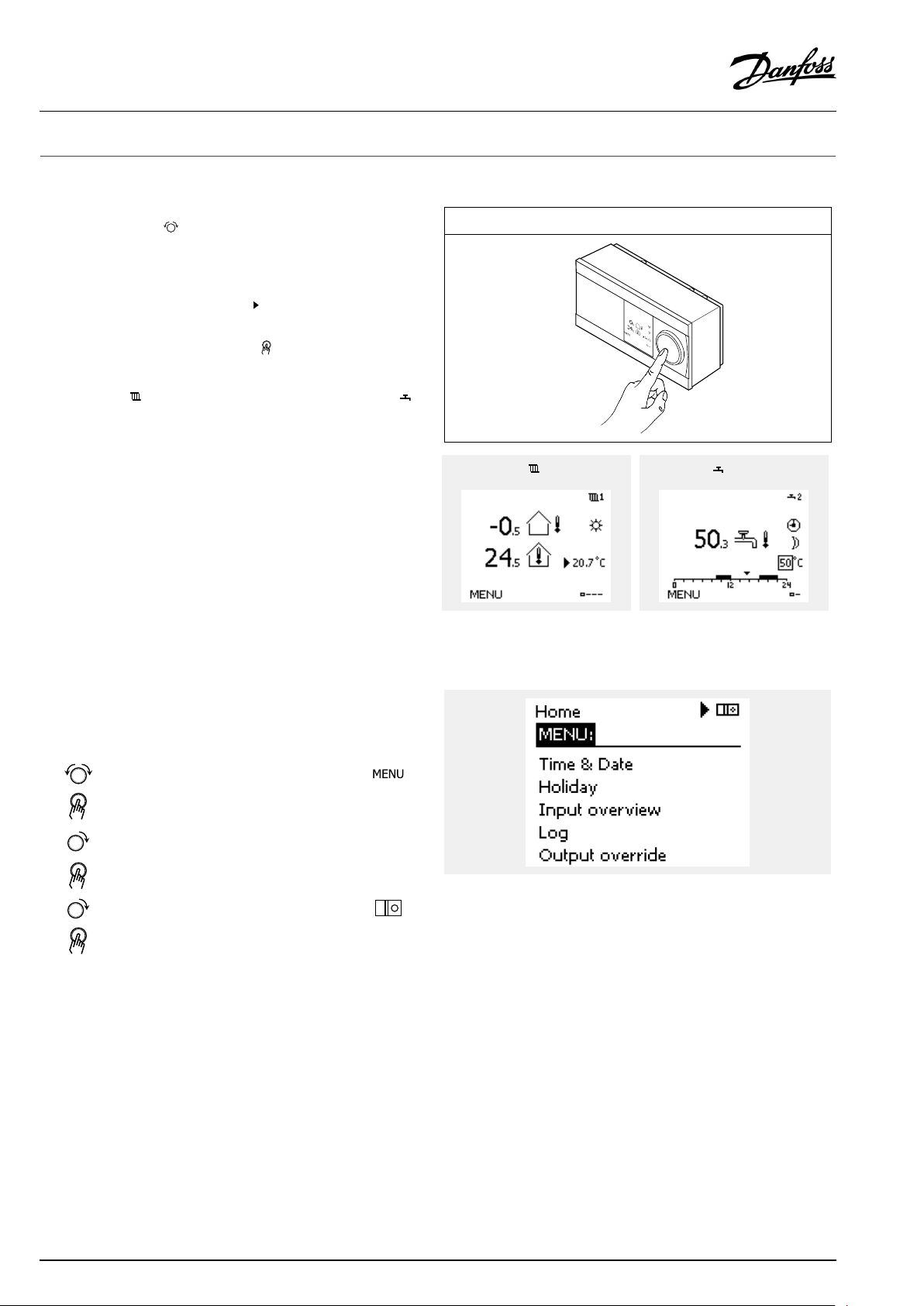
3.0Dailyuse
3.1Howtonavigate
Younavigateinthecontrollerbyturningthedialleftorrightto
thedesiredposition().
Thedialhasabuilt-inaccellerator.Thefasteryouturnthedial,the
fasteritreachesthelimitsofanywidesettingrange.
Thepositionindicatorinthedisplay(
youare.
Pushthedialtoconfirmyourchoices().
Thedisplayexamplesarefromatwo-circuitapplication:One
heatingcircuit()andonedomestichot-water(DHW)circuit().
Theexamplesmightdifferfromyourapplication.
)willalwaysshowyouwhere
ExampleshowsECL210/310
Heatingcircuit():DHWcircuit();
Somegeneralsettingswhichapplytotheentirecontrollerare
locatedinaspecificpartofthecontroller.
Toenter‘Commoncontrollersettings’:
Action:Purpose:
Choose‘MENU’inanycircuit
Confirm
Choosethecircuitselectoratthetop
rightcornerinthedisplay
Confirm
Choose‘Commoncontrollersettings’
Confirm
Examples:
Circuitselector
50|©Danfoss|2021.12
AQ192386469094en-010802
Page 51
OperatingGuideECLComfort210/296/310,applicationA247/A347
3.2Understandingthecontrollerdisplay
ThissectiondescribesthefunctioningeneralfortheECLComfort
210/296/310series.Theshowndisplaysaretypicalandnot
applicationrelated.Theymightdifferfromthedisplaysinyour
application.
Choosingafavoritedisplay
Yourfavoritedisplayisthedisplayyouhavechosenasthedefault
display.Thefavoritedisplaywillgiveyouaquickoverviewofthe
temperaturesorunitsthatyouwanttomonitoringeneral.
Ifthedialhasnotbeenactivatedfor20min.,thecontrollerwill
reverttotheoverviewdisplayyouhavechosenasfavorite.
Toshiftbetweendisplays:Turnthedialuntilyoureachthedisplay
selector(
turntochooseyourfavoriteoverviewdisplay.Pushthedialagain.
)atthebottomrightsideofthedisplay.Pushthedialand
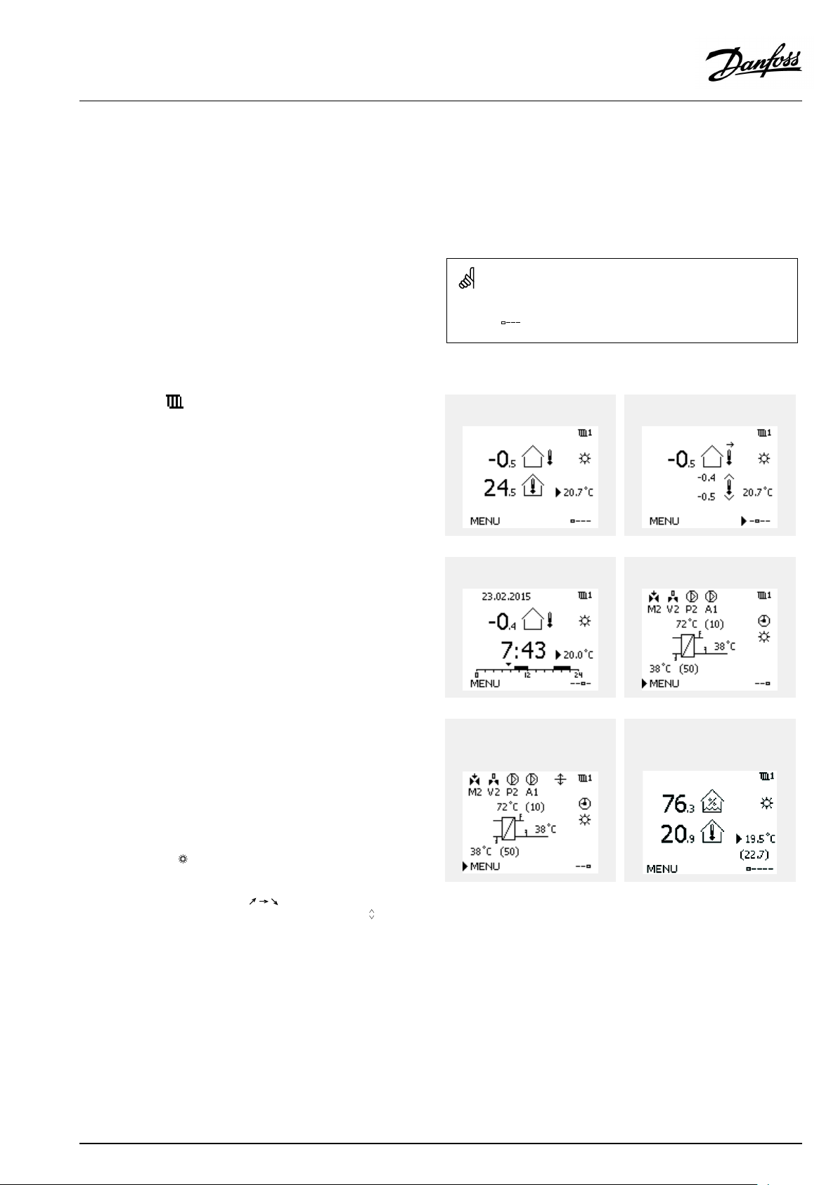
Heatingcircuit
Overviewdisplay1informsabout:
actualoutdoortemperature,controllermode,
actualroomtemperature,desiredroomtemperature.
Overviewdisplay2informsabout:
actualoutdoortemperature,trendinoutdoortemperature,
controllermode,max.andmin.outdoortemperaturessince
midnightaswellasdesiredroomtemperature.
Overviewdisplay3informsabout:
date,actualoutdoortemperature,controllermode,time,desired
roomtemperatureaswellasshowsthecomfortscheduleofthe
currentday.
Overviewdisplay4informsabout:
stateofthecontrolledcomponents,actualflowtemperature,
(desiredflowtemperature),controllermode,returntemperature
(limitationvalue),influenceondesiredflowtemperature.
ThevalueabovetheV2symbolindicates0–100%oftheanalogue
signal(0–10V).
Note:
Anactualflowtemperaturevaluemustbepresent,otherwisethe
circuit'scontrolvalvewillclose.
Overviewdisplay1:Overviewdisplay2:
Overviewdisplay3:Overviewdisplay4:
Exampleofoverviewdisplaywith
Influenceindication:
Example,favoritedisplay1in
A230.3,wheremin.desiredroom
temperatureisindicated(22.7):
Dependentonthechosendisplay,theoverviewdisplaysforthe
heatingcircuitinformyouabout:
•actualoutdoortemperature(-0.5)
•controllermode()
•actualroomtemperature(24.5)
•desiredroomtemperature(20.7°C)
•trendinoutdoortemperature(
)
•min.andmax.outdoortemperaturessincemidnight(
•date(23.02.2010)
•time(7:43)
•comfortscheduleofthecurrentday(0-12-24)
•stateofthecontrolledcomponents(M2,P2)
•actualflowtemperature(49°C),(desiredflowtemperature(31))
•returntemperature(24°C)(limitationtemperature(50))
AQ192386469094en-010802
)
©Danfoss|2021.12|51
Page 52
OperatingGuideECLComfort210/296/310,applicationA247/A347
Thesettingofthedesiredroomtemperatureisimportantevenifa
roomtemperaturesensor/RemoteControlUnitisnotconnected.
Ifthetemperaturevalueisdisplayedas
"--"
thesensorinquestionisnotconnected.
"---"
thesensorconnectionisshort-circuited.
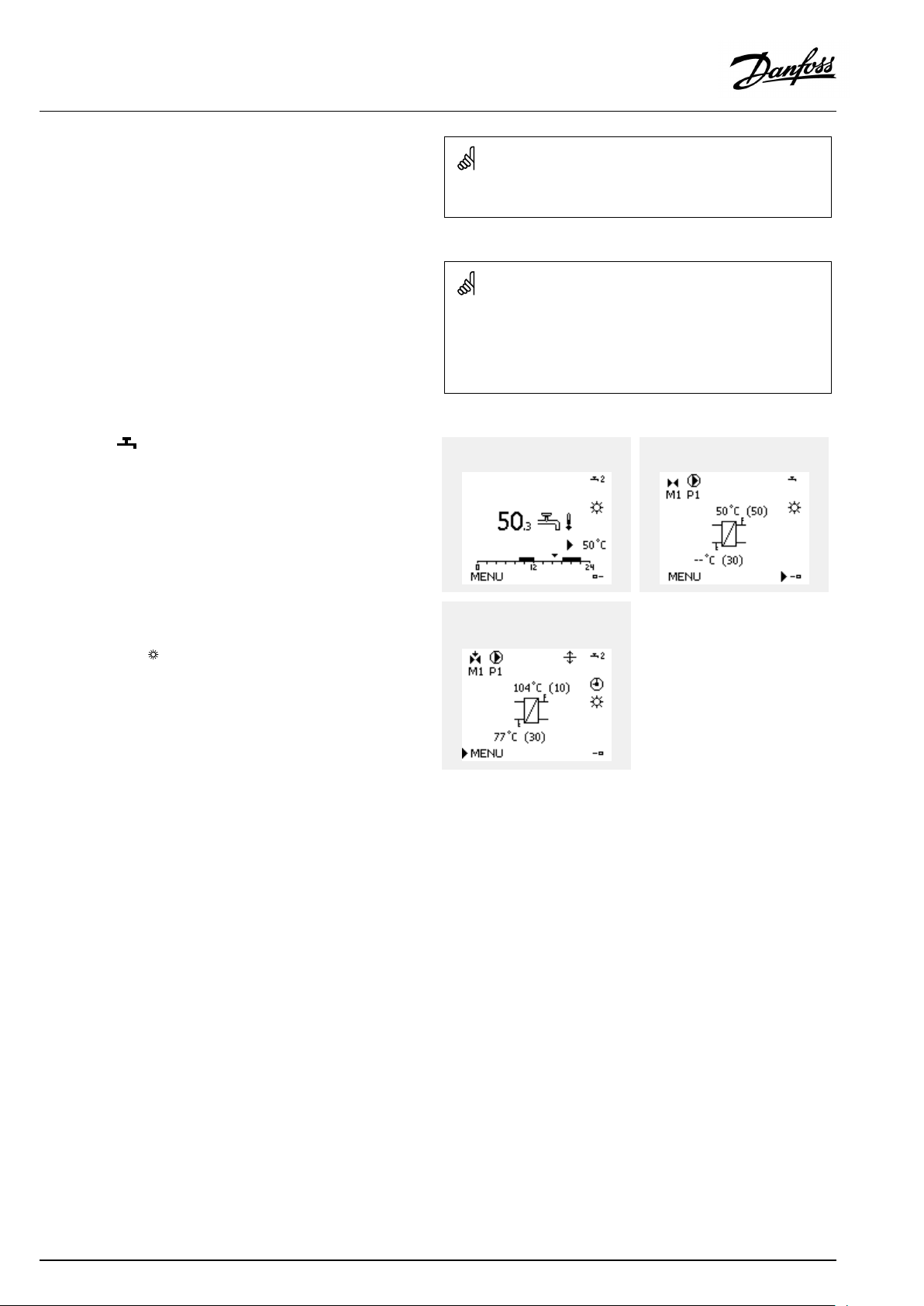
DHWcircuit
Overviewdisplay1informsabout:
actualDHWtemperature,controllermode,desiredDHW
temperatureaswellasthecomfortscheduleofthecurrentday.
Overviewdisplay2informsabout:
stateofthecontrolledcomponents,actualDHWtemperature,
(desiredDHWtemperature),controllermode,returntemperature
(limitationvalue),influenceondesiredDHWtemperature.
Dependentonchosendisplay,theoverviewdisplaysfortheDHW
circuitinformyouabout:
•actualDHWtemperature(50.3)
•controllermode(
)
•desiredDHWtemperature(50°C)
•comfortscheduleofthecurrentday(0-12-24)
•stateofthecontrolledcomponents(M1,P1)
•actualDHWtemperature(50°C),(desiredDHWtemperature(50))
•returntemperature(--°C)(limitationtemperature(30))
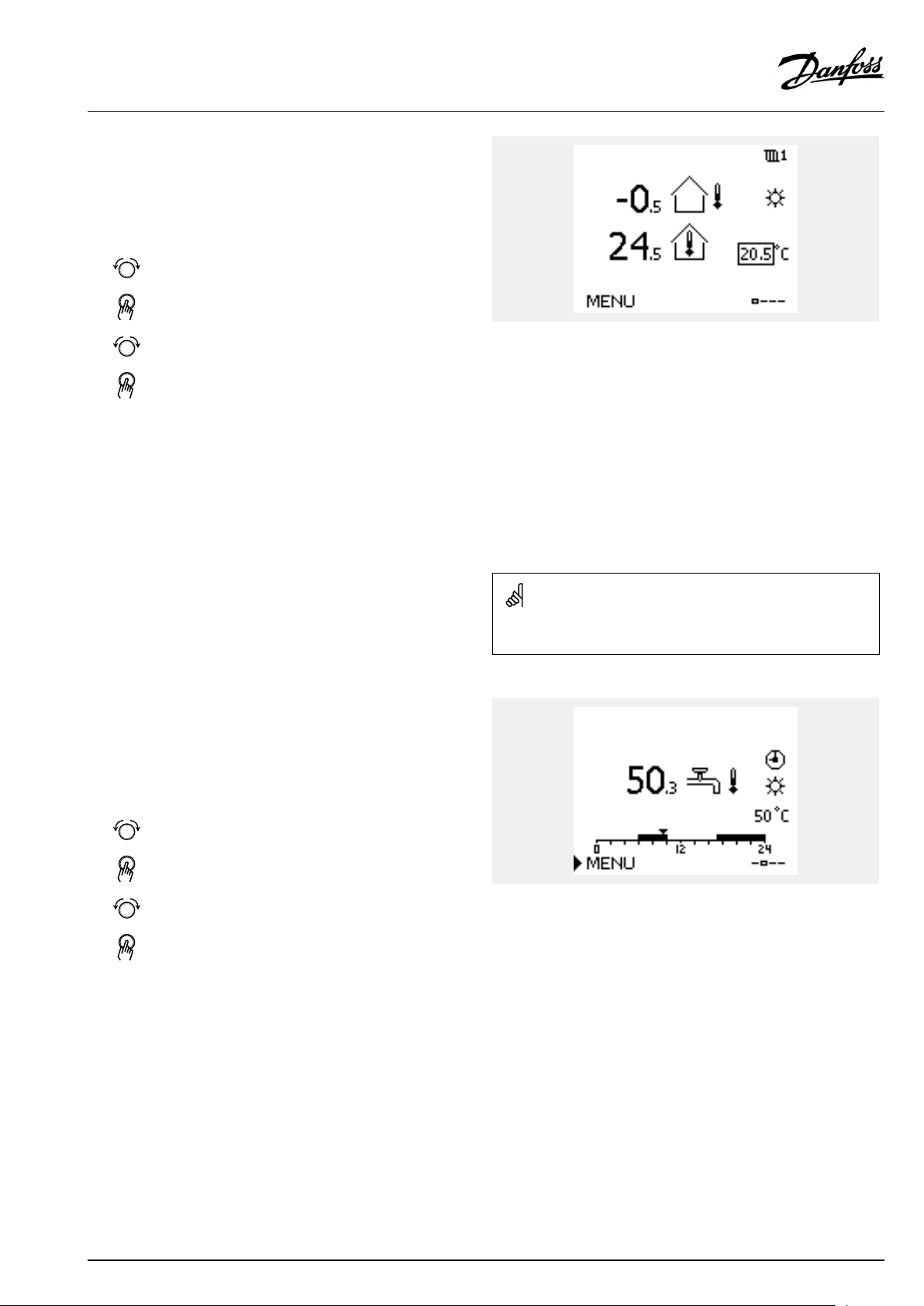
Settingthedesiredtemperature
Dependingonthechosencircuitandmode,itispossibletoenter
alldailysettingsdirectlyfromtheoverviewdisplays(seealsothe
nextpageconcerningsymbols).
Overviewdisplay1:Overviewdisplay2:
Exampleofoverviewdisplaywith
Influenceindication:
52|©Danfoss|2021.12
AQ192386469094en-010802
Page 53
OperatingGuideECLComfort210/296/310,applicationA247/A347
Settingthedesiredroomtemperature
Thedesiredroomtemperaturecaneasilybeadjustedinthe
overviewdisplaysfortheheatingcircuit.
Action:Purpose:
Desiredroomtemperature
Confirm
Adjustthedesiredroomtemperature
Confirm
Thisoverviewdisplayinformsaboutoutdoortemperature,actual
roomtemperatureaswellasdesiredroomtemperature.
Thedisplayexampleisforcomfortmode.Ifyouwanttochange
thedesiredroomtemperatureforsavingmode,choosethemode
selectorandselectsaving.
Examples:
20.5
21.0
Thesettingofthedesiredroomtemperatureisimportantevenifa
roomtemperaturesensor/RemoteControlUnitisnotconnected.
SettingthedesiredDHWtemperature
ThedesiredDHWtemperaturecaneasilybeadjustedinthe
overviewdisplaysfortheDHWcircuit.
Action:Purpose:
DesiredDHWtemperature
Confirm
AdjustthedesiredDHWtemperature
Confirm
InadditiontotheinformationaboutdesiredandactualDHW
temperature,thetoday'sscheduleisvisible.
Thedisplayexampleindicatesthatthecontrollerisinscheduled
operationandincomfortmode.
Examples:
50
55
AQ192386469094en-010802
©Danfoss|2021.12|53
Page 54

OperatingGuideECLComfort210/296/310,applicationA247/A347
Settingthedesiredroomtemperature,ECA30/ECA31
Thedesiredroomtemperaturecanbesetexactlyasinthe
controller.However,othersymbolscanbepresentinthedisplay
(pleasesee'Whatdothesymbolsmean?').
WiththeECA30/ECA31youcanoverridethedesiredroom
temperaturesetinthecontrollertemporarilybymeansoftheoverride
functions:
54|©Danfoss|2021.12
AQ192386469094en-010802
Page 55

OperatingGuideECLComfort210/296/310,applicationA247/A347
3.3Ageneraloverview:Whatdothesymbolsmean?
Symbol
Description
Outdoortemp.
Relativehumidityindoor
Roomtemp.
DHWtemp.
Positionindicator
Scheduledmode
Comfortmode
Savingmode
Frostprotectionmode
Manualmode
Standby
Coolingmode
Symbol
Temperature
Mode
Description
Alarm
Letter
Event
Monitoringtemperaturesensor
connection
Displayselector
Max.andmin.value
Trendinoutdoortemperature
Windspeedsensor
Sensornotconnectedornotused
Sensorconnectionshort-circuited
Fixedcomfortday(holiday)
Activeinfluence
Heatingactive(+)
Coolingactive(-)
Activeoutputoverride
Optimizedstartorstoptime
Heating
Cooling
DHW
Commoncontrollersettings
PumpON
PumpOFF
FanON
FanOFF
Actuatoropens
Actuatorcloses
Actuator,analoguecontrol
signal
Pump/fanspeed
DamperON
Circuit
Controlled
component
Numberofheatexchangers
Additionalsymbols,ECA30/31:
Symbol
InECA30/31onlythesymbolsthatarerelevanttotheapplicationin
thecontrolleraredisplayed.
Description
ECARemoteControlUnit
Connectionaddress(master:15,slaves:1-9)
15
Dayoff
Holiday
Relaxing(extendedcomfortperiod)
Goingout(extendedsavingperiod)
DamperOFF
AQ192386469094en-010802
©Danfoss|2021.12|55
Page 56
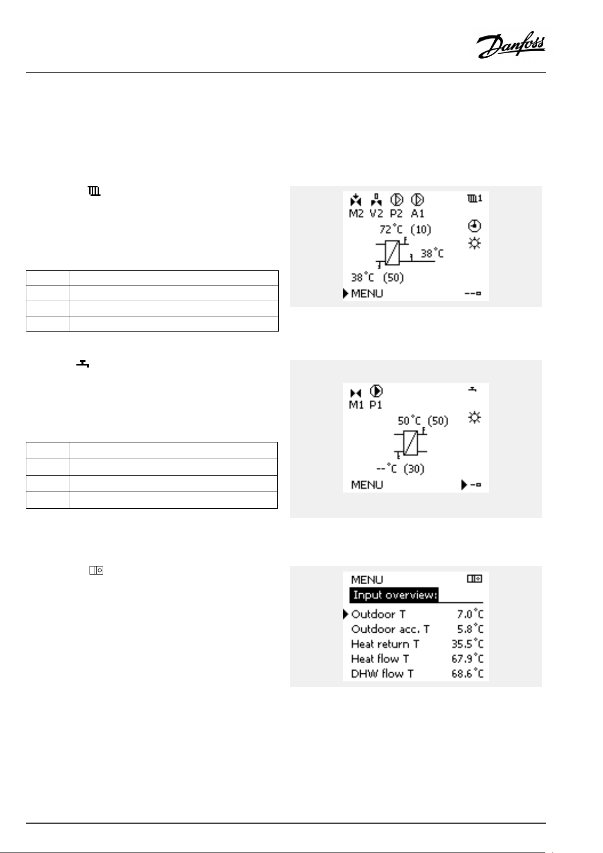
OperatingGuideECLComfort210/296/310,applicationA247/A347
3.4Monitoringtemperaturesandsystemcomponents
ThissectiondescribesthefunctioningeneralfortheECLComfort
210/296/310series.Theshowndisplaysaretypicalandnot
applicationrelated.Theymightdifferfromthedisplaysinyour
application.
Heatingcircuit
Theoverviewdisplayintheheatingcircuitensuresaquick
overviewoftheactualand(desired)temperaturesaswellasthe
actualstateofthesystemcomponents.
Displayexample:
49°C
(31)
24°C
(50)
DHWcircuit
TheoverviewdisplayintheDHWcircuitensuresaquickoverview
oftheactualand(desired)temperaturesaswellastheactualstate
ofthesystemcomponents.
Displayexample(heatexchanger):
50°C
(50)
(30)
Flowtemperature
Desiredflowtemperature
Returntemperature
Returntemperaturelimitation
Flowtemperature
Desiredflowtemperature
--
Returntemperature:sensornotconnected
Returntemperaturelimitation
Displayexamplewithheatexchanger:
Inputoverview
Anotheroptiontogetaquickoverviewofmeasuredtemperatures
isthe'Inputoverview'whichisvisibleinthecommoncontroller
settings(howtoenterthecommoncontrollersettings,see
‘Introductiontocommoncontrollersettings’ .)
Asthisoverview(seedisplayexample)onlystatesthemeasured
actualtemperatures,itisread-only.
56|©Danfoss|2021.12
AQ192386469094en-010802
Page 57
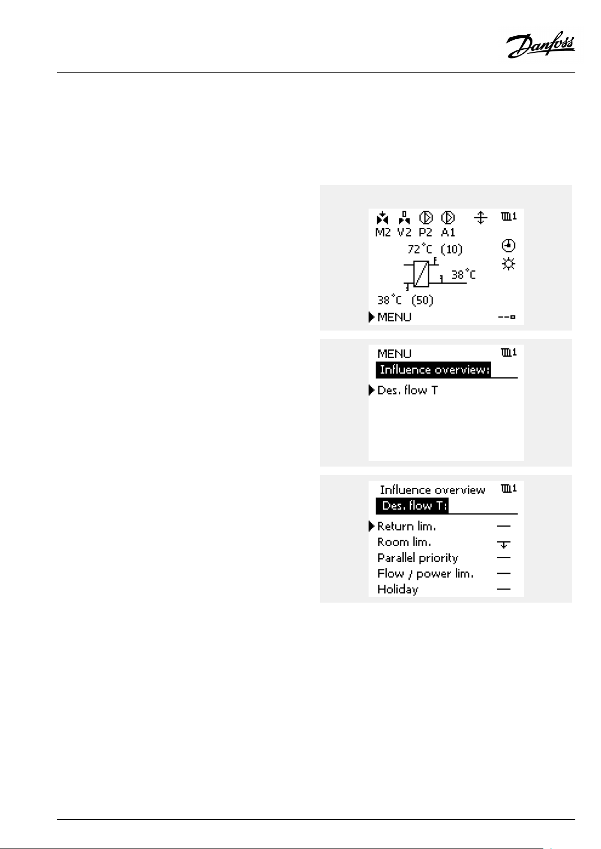
OperatingGuideECLComfort210/296/310,applicationA247/A347
3.5Influenceoverview
ThissectiondescribesthefunctioningeneralfortheECLComfort
210/296/310series.Theshowndisplaysaretypicalandnot
applicationrelated.Theymightdifferfromthedisplaysinyour
application.
Themenugivesanoverviewoftheinfluencesonthedesired
flowtemperature.Itdiffersfromapplicationtoapplicationwhich
parametersarelisted.Itcanbehelpfulinaservicesituationto
explainunexpectedconditionsortemperaturesamongothers.
Ifthedesiredflowtemperatureisinfluenced(corrected)byoneor
moreparameters,itisindicatedbyasmalllinewitharrow-down,
arrow-upordouble-arrow:
Arrow-down:
Theparameterinquestionreducesthedesiredflowtemperature.
Arrow-up:
Theparameterinquestionincreasesthedesiredflowtemperature.
Double-arrow:
Theparameterinquestioncreatesanoverride(e.g.Holiday).
Straightline:
Noactiveinfluence.
Intheexample,thearrowinthesymbolpointsdownwardsfor
'Roomlim. ' .Thismeansthattheactualroomtemperatureis
higherthanthedesiredroomtemperaturewhichagainresultsina
decreaseofthedesiredflowtemperature.
ExampleofoverviewdisplaywithInfluenceindication:
AQ192386469094en-010802
©Danfoss|2021.12|57
Page 58

OperatingGuideECLComfort210/296/310,applicationA247/A347
3.6Manualcontrol
ThissectiondescribesthefunctioningeneralfortheECLComfort
210/296/310series.Theshowndisplaysaretypicalandnot
applicationrelated.Theymightdifferfromthedisplaysinyour
application.
Itispossibletomanuallycontroltheinstalledcomponents.
Manualcontrolcanonlybeselectedinfavoritedisplaysinwhich
thesymbolsforthecontrolledcomponents(valve,pumpetc.)are
visible.
Action:Purpose:
Choosemodeselector
Confirm
Choosemanualmode
Confirm
Choosepump
Confirm
SwitchONthepump
SwitchOFFthepump.
Confirmpumpmode
Choosemotorizedcontrolvalve
Confirm
Openthevalve
Stopopeningthevalve
Closethevalve
Examples:
ControlledcomponentsCircuitselector
Duringmanualoperation:
•Allcontrolfunctionsaredeactivated
•Outputoverrideisnotpossible
•Frostprotectionisnotactive
Stopclosingthevalve
Confirmvalvemode
Toleavemanualcontrol,usethemodeselectortoselectthe
desiredmode.Pushthedial.
Manualcontrolistypicallyusedwhencommisioningthe
installation.Thecontrolledcomponents,valve,pumpetc.,canbe
controlledforcorrectfunction.
58|©Danfoss|2021.12
Whenmanualcontrolisselectedforonecircuit,itisautomatically
selectedforallcircuits!
AQ192386469094en-010802
Page 59

OperatingGuideECLComfort210/296/310,applicationA247/A347
3.7Schedule
3.7.1Setyourschedule
ThissectiondescribesthescheduleingeneralfortheECLComfort
210/296/310series.Theshowndisplaysaretypicalandnot
applicationrelated.Theymightdifferfromthedisplaysinyour
application.Insomeapplications,however,theremightbemore
thanoneschedule.Additionalschedulescanbefoundin‘Common
controllersettings’ .
Thescheduleconsistsofa7-dayweek:
=
M
Monday
=
T
Tuesday
=
W
Wednesday
=
T
Thursday
=
F
Friday
=
S
Saturday
=
S
Sunday
Theschedulewillday-by-dayshowyouthestartandstoptimesof
yourcomfortperiods(heating/DHWcircuits).
Changingyourschedule:
Action:
Purpose:
Choose'MENU'inanyoftheoverview
displays
Confirm
Confirmthechoice'Schedule'
Choosethedaytochange
Confirm*
GotoStart1
Confirm
Adjustthetime
Confirm
GotoStop1,Start2etc.etc.
Returnto'MENU'
Confirm
Choose'Yes'or'No'in'Save'
Confirm
Examples:
*Severaldayscanbemarked
Thechosenstartandstoptimeswillbevalidforallthechosendays
(inthisexampleThursdayandSaturday).
Youcansetmax.3comfortperiodsaday.Youcandeleteacomfort
periodbysettingstartandstoptimestothesamevalue.
AQ192386469094en-010802
Eachcircuithasitsownschedule.Tochangetoanothercircuit,goto
'Home',turnthedialandchoosethedesiredcircuit.
Thestartandstoptimescanbesetinhalf-hourly(30min.)intervals.
©Danfoss|2021.12|59
Page 60

OperatingGuideECLComfort210/296/310,applicationA247/A347
4.0Settingsoverview
Forfactorysettingsandsettingrange,seeappendix“ParameterIDoverview” .
ParametersindicatedwithanIDno.like"1x607"meanauniversalparameter.xstandsforcircuit/parametergroup.
SettingIDPage
Heatcurve
Ext.desiredT—(ECLComfort310)
Actual(actualfloworpower)
Xpactual
Extendedheatcut-outsetting
Extendedwintercut-outsetting
Day
Starttime
Duration
DesiredT
DesiredT(Desiredflowtemperature)
ECAaddr.(ECAaddress,choiceofRemoteControlUnit)
Autosaving(savingtemp.dependentonoutdoortemp.)
Boost
Ramp(referenceramping)
Optimizer(optimizingtimeconstant)
Adapt.time(adaptiontime)
Demandoffset
Basedon(optimizationbasedonroom/outdoortemp.)
Totalstop
Pexercise(pumpexercise)
Mexercise(valveexercise)
Actuator
Pre-stop(optimizedstoptime)
Con.T,re.Tlim.(Constanttemperaturemode,return
temperaturelimitation)
DHW,ret.Tlimit
Limit(returntemp.limitation)
HighToutX1(returntemp.limitation,highlimit,X-axis)
LowlimitY1(returntemp.limitation,lowlimit,Y-axis)
LowToutX2(returntemp.limitation,lowlimit,X-axis)
HighlimitY2(returntemp.limitation,highlimit,Y-axis)
Infl.-max.(returntemp.limitation-max.influence)
Infl.-min.(returntemp.limitation-min.influence)
Adapt.time(adaptationtime)
Ppost-run
DHWPpost-run(DHWpump,post-run)
Char.Ppost-run(DHWchargingpump,post-run)
Paralleloperation
1x00465
1x01093
1x01181
1x01282
1x01383
1x01483
1x01568
1x01793
1x02084
1x02184
1x02294
1x02395
1x02489
1x02685
1x02872
1x02972
1x03073
1x03173
1x03273
1x03373
1x034
1x035
1x036
1x037
1x04095
1x04195
1x04295
1x04385
Factorysettingsincircuit(s)
1
64
66
77
90
105
105
116
116
117
117
74
74
74
74
60|©Danfoss|2021.12
AQ192386469094en-010802
Page 61

OperatingGuideECLComfort210/296/310,applicationA247/A347
SettingIDPage
Max.DHWtime
DHWdeact.time(DHWdeactivationtime)
Pdemand
DHWpriority(closedvalve/normaloperation)
Cont.Tcontrol
Circ.Ppriority
Pchargedelay(Chargingpump,delayedstart)
FlowTadapttime(Flowtemperature,adaptationtime)
Circ.PfrostT
PfrostT(circulationpump,frostprotectiontemp.)
PheatT(heatdemand)
Priority(priorityforreturntemp.limitation)
Frostpr.T(frostprotectiontemp.)
Inputtype
Limit(limitationvalue)
Adapt.time(adaptationtime)
Filterconstant
Pulse
Units
HighlimitY2(flow/powerlimitation,highlimit,Y-axis)
LowlimitY1(flow/powerlimitation,lowlimit,Y-axis)
LowToutX2(flow/powerlimitation,lowlimit,X-axis)
HighToutX1(flow/powerlimitation,highlimit,X-axis)
Ext.input(externaloverride)
Ext.mode(externaloverridemode)
Upperdifference
Lowerdifference
Delay,example
Lowesttemp.
Max.chargeT(maximumheating/chargingtemperature)
Motorpr.(motorprotection)
Temp.min.
Temp.max.
Summer,cut-out(limitforheatingcut-out)
Infl.-max.(roomtemp.limitation,max.)
Infl.-min.(roomtemp.limitation,min.)
Xp(proportionalband)
Tn(integrationtimeconstant)
Mrun(runningtimeofthemotorizedcontrolvalve)
Nz(neutralzone)
Min.act.time(min.activationtimegearmotor)
Chargedifference
1x04496
1x04596
1x05096
1x05297
1x05497
1x05597
1x05998
1x068107
1x07698
1x07798
1x07898
1x085
1x09399
1x10⁹
1x111
1x11278
1x11378
1x114
1x115
1x11679
1x117
1x11880
1x11980
1x141
1x142100
1x147
1x148113
1x149
1x150
1x152107
1x174
1x177
1x17866
1x17986
1x18268
1x18369
1x18490
1x18590
1x18690
1x18791
1x18991
1x193107
Factorysettingsincircuit(s)
1
75
77
78
78
79
79
99
113
114
114
89
66
AQ192386469094en-010802
©Danfoss|2021.12|61
Page 62

OperatingGuideECLComfort210/296/310,applicationA247/A347
Stopdifference
Startdifference
SenddesiredT
SettingIDPage
1x194108
1x195110
1x500102
Factorysettingsincircuit(s)
1
62|©Danfoss|2021.12
AQ192386469094en-010802
Page 63

OperatingGuideECLComfort210/296/310,applicationA247/A347
5.0Settings
5.1IntroductiontoSettings
Descriptionsofsettings(parameter'sfunctions)aredividedinto
groupsasusedintheECLComfort210/296/310controller's
menustructure.Examples:"Flowtemperature" ,"Roomlimit"and
soon.Eachgroupstartswithageneralexplanation.
Thedescriptionsofeachparameterareinnumericorder,relatedto
theparameter'sIDnumbers.Youmightcomeacrossdifferences
betweentheorderinthisOperatingGuideandtheECLComfort
210/296/310controllers.
Someparameterdescriptionsarerelatedtospecificapplication
subtypes.Thismeansthatyoumightnotseetherelatedparameter
intheactualsubtypeintheECLcontroller.
Thenote"SeeAppendix… "referstotheAppendixattheendof
thisOperatingGuide,whereparameter'ssettingrangesandfactory
settingsarelisted.
Thenavigationhints(forexampleMENU>Settings>Returnlimit
…)covermultiplesubtypes.
AQ192386469094en-010802
©Danfoss|2021.12|63
Page 64

OperatingGuideECLComfort210/296/310,applicationA247/A347
5.2Flowtemperature
TheECLComfortcontrollerdeterminesandcontrolstheflow
temperaturerelatedtotheoutdoortemperature.Thisrelationship
iscalledtheheatcurve.
Theheatcurveissetbymeansof6coordinatepoints.Thedesired
flowtemperatureissetat6pre-definedoutdoortemperature
values.
Theshownvaluefortheheatcurveisanaveragevalue(slope),
basedontheactualsettings.
Desiredflowtemperature
Outdoor
temp.
Desiredflowtemp.
A
BC
Your
settings
-30°C45°C75°C95°C
-15°C40°C60°C90°C
-5°C35°C50°C80°C
0°C32°C45°C70°C
5°C30°C40°C60°C
15°C25°C28°C35°C
A:Exampleforfloorheating
B:Factorysettings
C:Exampleforradiatorheating(highdemand)
MENU>Settings>Flowtemperature
Heatcurve
1
0.1...4.01.0
Theheatcurvecanbechangedintwoways:
1.Thevalueoftheslopeischanged(seeheatcurveexamples
onnextpage)
2.Thecoordinatesoftheheatcurvearechanged
Changethevalueoftheslope:
Pushthedialtoenter/changetheslopevalueoftheheatcurve
(example:1.0).
Whentheslopeoftheheatcurveischangedbymeansoftheslope
value,thecommonpointforallheatcurveswillbeadesiredflow
temperature=24.6°Catanoutdoortemperature=20°Canda
desiredroomtemperature=20.0°C.
Slopechanges
Coordinatechanges
Changethecoordinates:
Pushthedialtoenter/changethecoordinatesoftheheatcurve
(example:-30,75).
Theheatcurverepresentsthedesiredflowtemperaturesat
differentoutdoortemperaturesandatadesiredroomtemperature
of20°C.
Ifthedesiredroomtemperatureischanged,thedesiredflow
temperaturealsochanges:
(DesiredroomT-20)×HC×2.5
where"HC"istheHeatCurveslopeand"2.5"isaconstant.
64|©Danfoss|2021.12
Thecalculatedflowtemperaturecanbeinfluencedbythe‘Boost’and
‘Ramp’functionsetc.
Example:
Heatcurve:
Desiredflowtemp.:
Desiredroomtemp.:
Calculation(22–20)×1.0×2.5=
Result:
Thedesiredflowtemperaturewillbecorrectedfrom50°Cto55°C.
1.0
50°C
22°C
5
AQ192386469094en-010802
Page 65
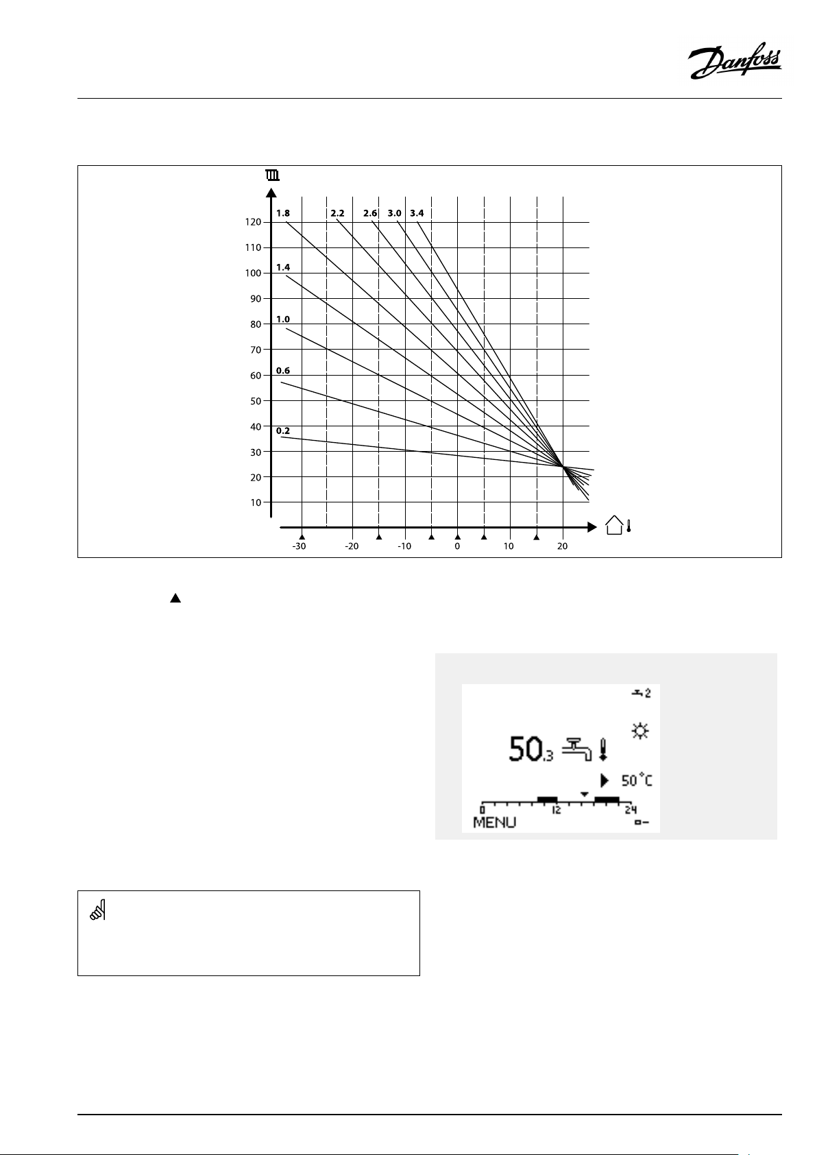
OperatingGuideECLComfort210/296/310,applicationA247/A347
Choosingaheatcurveslope
Theheatcurvesrepresentthedesiredflowtemperatureatdifferentoutdoortemperaturesandatadesiredroomtemperatureof20°C.
Thesmallarrows()indicate6differentoutdoortemperaturevaluesatwhichyoucanchangetheheatcurve.
TheECLComfort210/296/310controlstheDHWtemperature
accordingtothedesiredflowtemperatureforexampleunderthe
influenceofthereturntemperature.
ActualDHWtemp.
ThedesiredDHWtemperatureissetintheoverviewdisplay.
50.3:
50:
ActualDHWtemperature
DesiredDHWtemperature
ParametersindicatedwithanIDno.like"1x607"meanauniversal
parameter.
xstandsforcircuit/parametergroup.
DesiredDHW
temp.
AQ192386469094en-010802
©Danfoss|2021.12|65
Page 66

OperatingGuideECLComfort210/296/310,applicationA247/A347
MENU>Settings>Flowtemperature
DesiredT(Desiredflowtemperature)
WhentheECLComfortisinoverridemode,type"Const.T",thedesiredflow
temperaturecanbeset.
A"Const.T"relatedreturntemperaturelimitationcanalsobeset.SeeMENU
>Settings>Returnlimit>'Con.T,ret.Tlim. '
1x004
SeeAppendix“ParameterIDoverview”
MENU>Settings>Flowtemperature
Temp.min.
1x177
SeeAppendix“ParameterIDoverview”
Setthemin.flowtemperatureforthesystem.Thedesiredflow
temperaturewillnotbelowerthanthissetting.Adjustthefactory
setting,ifrequired.
Overridemode
WhenECLComfortisinScheduledmode,acontact(switch)signalcan
beappliedtoaninputinordertooverridetoComfort,Saving,Frost
ProtectionorConstanttemperature.Aslongasthecontact(switch)
signalisapplied,theoverrideisactive.
The"DesiredT"valuecanbeinfluencedby:
•temp.max.
•temp.min.
•roomtemp.limit
•returntemp.limit
•flow/powerlimit
‘Temp.min.’isoverruledif'Totalstop'isactiveinSavingmodeor
'Cut-out'isactive.
‘Temp.min.’canbeoverruledbytheinfluencefromthereturn
temperaturelimitation(see'Priority').
MENU>Settings>Flowtemperature
Temp.max.
1x178
SeeAppendix“ParameterIDoverview”
Setthemax.flowtemperatureforthesystem.Thedesired
temperaturewillnotbehigherthanthissetting.Adjustthefactory
setting,ifrequired.
Thesettingfor‘Temp.max. ’hashigherprioritythan‘Temp.min.’ .
Thesettingof‘heatcurve’ispossibleforheatingcircuitsonly.
Thesettingfor‘Temp.max. ’hashigherprioritythan‘Temp.min.’ .
66|©Danfoss|2021.12
AQ192386469094en-010802
Page 67

OperatingGuideECLComfort210/296/310,applicationA247/A347
Externalsignalfordesiredflowtemperature
Avoltage(0-10V)canbeappliedtotheinputterminalS10in
ordertodeterminethedesiredflowtemperature.
ThemeasuredvoltageoninputS10mustbeconvertedtoa
temperaturevaluebythecontroller.Whenthevoltagegetshigher,
thedesiredflowtemperatureincreases.
Thefollowingsettingssetupthescaling.
MENU>Settings>Flowtemperature
Ext.desiredT—(ECLComfort310)
CircuitSettingrange
1
Theactualdesiredflowtemperatureisindicatedbytheunit°C.
Read-outonly
Factorysetting
Read-out:
--:
°C:
Externalvoltagesignalisnotconnected..
Externalvoltagesignalconvertedtodesiredflow
temperature.
Pushthedialtoseethegraphandenterthevaluesetsfortheinput
voltage(1and10volt)anddisplayeddesiredflowtemperature.
Example:Relationshipbetweeninputvoltageanddisplayeddesiredflow
temperature
Desiredflowtemp.(°C)
Volt
Thisexampleshowsthat1voltcorrespondsto10.0°Cand10volt
correspondto100°C.
Desiredflowtemperature:
10...120°C
Fixedvoltagesettings:1Vand10V
Factorysettings:
(1,10)and(10,100)
Thismeansthatthe‘Desiredflowtemperature’is10°Cat1.0V
and100°Cat10V.
Typically,thehigherthevoltage,thehigherthedisplayeddesired
flowtemperature.
Theexternalvoltagesignalmustbehigherthan1.0Vinorderto
activatetheoverride.
AQ192386469094en-010802
©Danfoss|2021.12|67
Page 68
OperatingGuideECLComfort210/296/310,applicationA247/A347
5.3Roomlimit
ThefollowingsectionisageneraldescriptionforRoom
temperaturelimitation.
Thissectionisonlyrelevantifyouhaveinstalledaroom
temperaturesensororaRemoteControlUnitforutilizingtheroom
temperaturesignal.
Inthefollowingdescriptionisreferredto"flowtemperature"in
general.
Thecontrolleradjuststhedesiredflowtemperaturetocompensate
forthedifferencebetweenthedesiredandtheactualroom
temperature.
Iftheroomtemperatureishigherthanthedesiredvalue,the
desiredflowtemperaturecanbereduced.
The'Infl.-max.'(Influence,max.roomtemp.)determineshow
muchthedesiredflowtemperatureshouldbereduced.
Usethisinfluencetypetoavoidatoohighroomtemperature.
Thecontrollerwillallowforfreeheatgains,i.e.solarradiationor
heatfromafireplaceetc.
Iftheroomtemperatureislowerthanthedesiredvalue,thedesired
flowtemperaturecanbeincreased.
The'Infl.-min.'(Influence,min.roomtemperature)determines
howmuchthedesiredflowtemperatureshouldbeincreased.
Usethisinfluencetypetoavoidatoolowroomtemperature.
Thiscouldforexamplebecausedbywindysurroundings.
Atypicalsettingwillbe-4.0for'Infl.-max.'and4.0for'Infl.-min. '
ParametersindicatedwithanIDno.like"1x607"meanauniversal
parameter.
xstandsforcircuit/parametergroup.
MENU>Settings>Roomlimit
Adapt.time(adaptiontime)
Controlshowfasttheactualroomtemperatureadaptstothedesiredroom
temperature(Icontrol).
1x015
SeeAppendix“ParameterIDoverview”
OFF:
Thecontrolfunctionisnotinfluencedbythe'Adapt.
time'.
Minor
Thedesiredroomtemperatureisadaptedquickly.
value:
Major
Thedesiredroomtemperatureisadaptedslowly.
value:
Theadaptationfunctioncancorrectthedesiredroomtemperature
withmax.8Kxheatcurveslopevalue.
68|©Danfoss|2021.12
AQ192386469094en-010802
Page 69
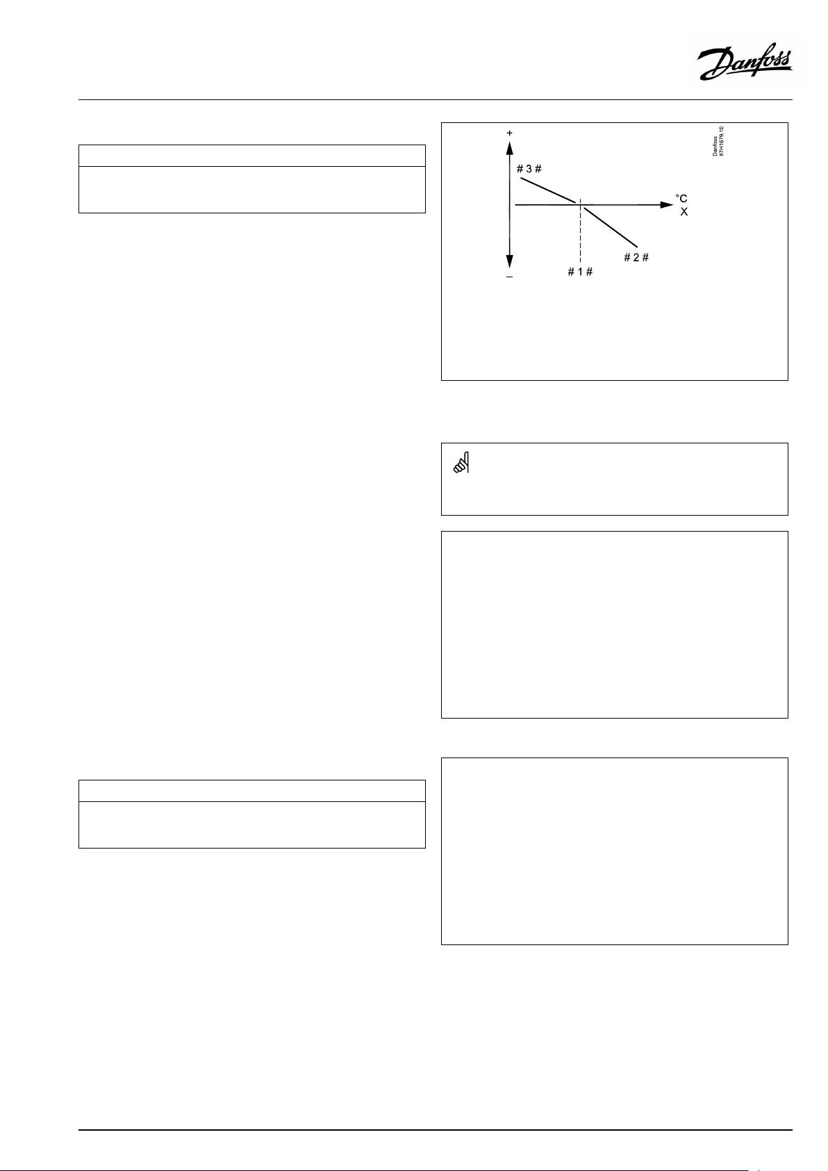
OperatingGuideECLComfort210/296/310,applicationA247/A347
MENU>Settings>Roomlimit
Infl.-max.(roomtemp.limitation,max.)
Determineshowmuchthedesiredflowtemperaturewillbeinfluenced
(decreased)iftheactualroomtemperatureishigherthanthedesiredroom
temperature(Pcontrol).
SeeAppendix“ParameterIDoverview”
0.0:
-2.0:
-5.0:
-9.9:
Noinfluence
Minorinfluence
Mediuminfluence
Maximuminfluence
1x182
=
X
#1#
#2#
#3#
Roomtemperature
=
Desiredroomtemperature
=
Negativeinfluence(1x082)whenactualroomtemp.getshigher
thandesiredroomtemp.
=
Positiveinfluence(1x083)whenactualroomtemp.getslowerthan
desiredroomtemp.
The‘Infl.-max.’and'Infl.-min. 'determinehowmuchtheroom
temperatureshouldinfluencethedesiredflowtemperature.
Ifthe‘Infl. ’factoristoohighand/orthe‘Adapt.time’toolow,thereis
ariskofunstablecontrol.
Example
Theactualroomtemperatureis2degreestoohigh.
The‘Infl.-max.’issetto-4.0.
Theheatcurveslopeis1.8(see'Heatcurve'in'Flowtemperature').
Result:
Thedesiredflowtemperatureischangedby(2x-4.0x1.8)
–14.4degrees.
MENU>Settings>Roomlimit
Infl.-min.(roomtemp.limitation,min.)
Determineshowmuchthedesiredflowtemperaturewillbeinfluenced
(increased)iftheactualroomtemperatureislowerthanthedesiredroom
temperature(Pcontrol).
SeeAppendix“ParameterIDoverview”
9.9:
5.0:
2.0:
0.0:
Maximuminfluence
Mediuminfluence
Minorinfluence
Noinfluence
Inapplicationsubtypes,whereaheatcurveslopevalueisnotpresent,
theheatcurveslopevalueissetto1:
Result:
Thedesiredflowtemperatureischangedby(2x-4.0x1):
–8.0degrees.
Example
1x183
Theactualroomtemperatureis2degreestoolow.
The‘Infl.-min.’issetto4.0.
Theheatcurveslopeis1.8(see'Heatcurve'in'Flowtemperature').
Result:
Thedesiredflowtemperatureischangedby(2x4.0x1.8)
14.4degrees.
Inapplicationsubtypes,whereaheatcurveslopevalueisnotpresent,
theheatcurveslopevalueissetto1:
Result:
Thedesiredflowtemperatureischangedby(2x4.0x1):
8.0degrees.
AQ192386469094en-010802
©Danfoss|2021.12|69
Page 70
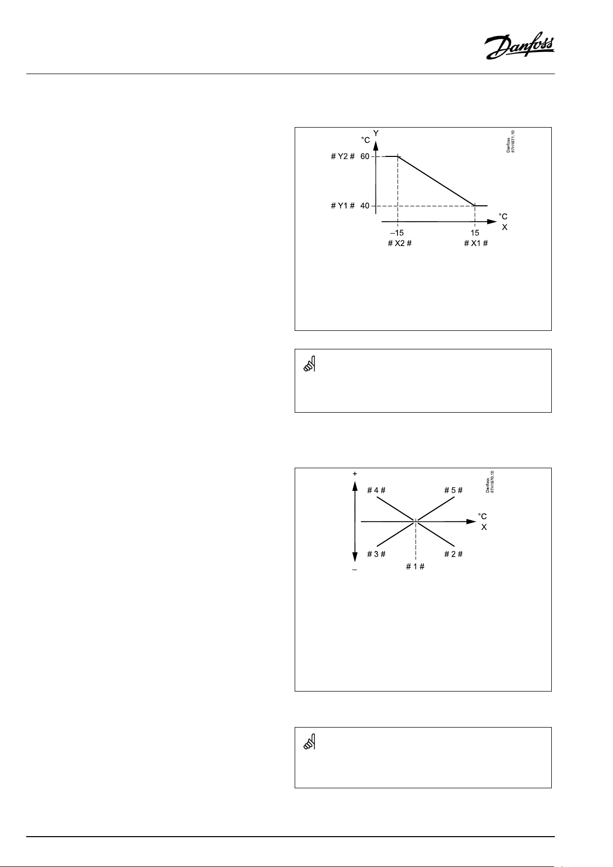
OperatingGuideECLComfort210/296/310,applicationA247/A347
5.4Returnlimit
Thereturntemperaturelimitationisbasedontheoutdoor
temperature.Typicallyindistrictheatingsystemsahigherreturn
temperatureisacceptedatadecreaseinoutdoortemperature.The
relationshipbetweenthereturntemperaturelimitsandoutdoor
temperatureissetintwocoordinates.
Theoutdoortemperaturecoordinatesaresetin'HighToutX1'
and'LowToutX2' .Thereturntemperaturecoordinatesaresetin
'HighlimitY2'and'LowlimitY1' .
Thecontrollerautomaticallychangesthedesiredflowtemperature
toobtainanacceptablereturntemperaturewhenthereturn
temperaturefallsbeloworgetshigherthanthecalculatedlimit.
ThislimitationisbasedonaPIregulationwhereP('Infl.'factor)
respondsquicklytodeviationsandI('Adapt.time')responds
slowerandovertimeremovesthesmalloffsetsbetweenthe
desiredandactualvalues.Thisisdonebychangingthedesired
flowtemperature.
X
Y
#X1#
#X2#
#Y1#
#Y2#
=
Outdoortemperature
=
Limitationtemperature
=
HighTout(1x031)
=
LowTout(1x033)
=
Lowlimit(1x032)
=
Highlimit(1x034)
DHWcircuit
Thereturntemperaturelimitationisbasedonaconstant
temperaturevalue.
Thecontrollerautomaticallychangesthedesiredflowtemperature
toobtainanacceptablereturntemperaturewhenthereturn
temperaturefallsbeloworgetshigherthanthesetlimit.
ThislimitationisbasedonaPIregulationwhereP('Infl.'factor)
respondsquicklytodeviationsandI('Adapt.time')responds
slowerandovertimeremovesthesmalloffsetsbetweenthe
desiredandactualvalues.Thisisdonebychangingthedesired
flowtemperature.
Thecalculatedlimitisshowninbrackets()inthemonitoringdisplay.
Seethesection"Monitoringtemperaturesandsystemcomponents" .
=
X
#1#
#2#
#3#
#4#
#5#
Returntemperature
=
Limitationtemperature
Negativeinfluence(1x035)whenreturntemp.getshigherthan
=
limit.temp.
Negativeinfluence(1x036)whenreturntemp.getslowerthan
=
limit.temp.
Positiveinfluence(1x036)whenreturntemp.getslowerthanlimit.
=
temp.
Positiveinfluence(1x035)whenreturntemp.getshigherthan
=
limit.temp.
70|©Danfoss|2021.12
Ifthe‘Infl. ’factoristoohighand/orthe‘Adapt.time’toolow,thereis
ariskofunstablecontrol.
AQ192386469094en-010802
Page 71
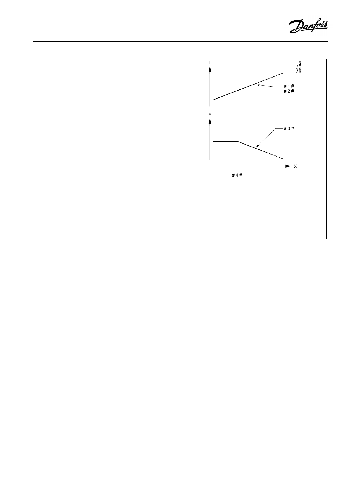
OperatingGuideECLComfort210/296/310,applicationA247/A347
Example,maximumreturntemperaturelimitation;
returntemperaturegetshigherthanlimit
=
T
Y
X
#1#
#2#
#3#
#4#
Temperature
=
Temperature
=
Time
=
Returntemperature
=
Returntemperaturelimit
=
Desiredflowtemperature
=
Actionpoint
AQ192386469094en-010802
©Danfoss|2021.12|71
Page 72
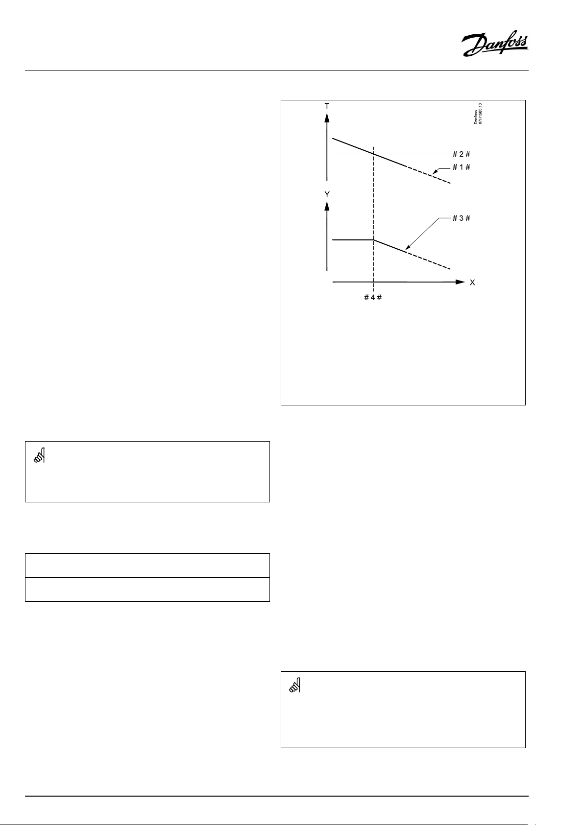
OperatingGuideECLComfort210/296/310,applicationA247/A347
Example,minimumreturntemperaturelimitation;
returntemperaturegetslowerthanlimit
=
T
Temperature
=
Y
Temperature
=
X
Time
=
#1#
Returntemperature
=
#2#
Returntemperaturelimit
=
#3#
Desiredflowtemperature
=
#4#
Actionpoint
ParametersindicatedwithanIDno.like"1x607"meanauniversal
parameter.
xstandsforcircuit/parametergroup.
MENU>Settings>Returnlimit
Con.T,re.Tlim.(Constanttemperaturemode,return
temperaturelimitation)
The"Con.T ,ret.Tlimit"isthereturntemperaturelimitationvaluewhenthe
circuitissettooverridemodetype"Const.T"(=Constanttemperature).
SeeAppendix“ParameterIDoverview”
Value:Setthereturntemperaturelimitation
1x028
Overridemode
WhenECLComfortisinScheduledmode,acontact(switch)signalcan
beappliedtoaninputinordertooverridetoComfort,Saving,Frost
ProtectionorConstanttemperature.Aslongasthecontact(switch)
signalisapplied,theoverrideisactive.
72|©Danfoss|2021.12
AQ192386469094en-010802
Page 73
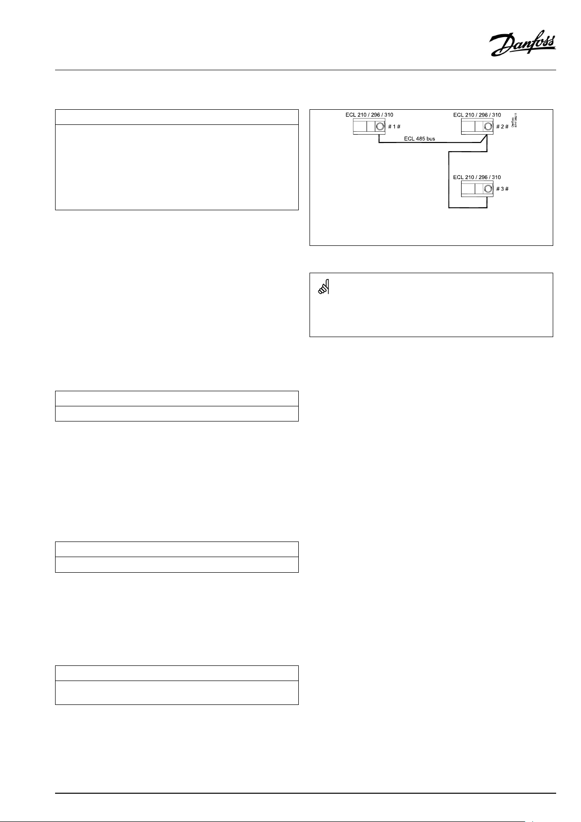
OperatingGuideECLComfort210/296/310,applicationA247/A347
MENU>Settings>Returnlimit
DHW,ret.Tlimit
WhenanaddressedslaveisactiveinDHW-tankheating/charging,the
returntemperaturelimitationinthemastercanbeset.
Notes:
•Themastercircuitmustbesettoreactonthedesiredflowtemperature
intheslave(s).See"Demandoffset"(ID11017).
•Theslave(s)mustbesettosendits/theirdesiredflowtemperatureto
themaster.See"SenddesiredT"(ID1x500).
SeeAppendix“ParameterIDoverview”
OFF:
Noinfluencefromslaves.Thereturntemperature
limitationisrelatedtosettingsin"Returnlimit" .
Value:Returntemperaturelimitationvaluewhenslaveisin
DHWtankheating/chargingoperation.
MENU>Settings>Returnlimit
Limit(returntemp.limitation)
Setthereturntemperaturevalueyouacceptforthesystem.
1x029
#1#=Master,exampleA266,address15
#2#=Slave,exampleA237,address9
#3#=Slave,exampleA367,address6
SomeexamplesofapplicationswithDHW-tankheating/chargingare:
•A217,A237,A247,A367,A377
1x030
SeeAppendix“ParameterIDoverview”
Whenthereturntemperaturefallsbeloworgetshigherthanthe
setvalue,thecontrollerautomaticallychangesthedesiredflow/
ducttemperaturetoobtainanacceptablereturntemperature.The
influenceissetin'Infl.-max. 'and'Infl.-min.' .
MENU>Settings>Returnlimit
HighToutX1(returntemp.limitation,highlimit,X-axis)
Settheoutdoortemperaturevalueforthelowreturntemperaturelimitation.
1x031
SeeAppendix“ParameterIDoverview”
ThecorrespondingYcoordinateissetin'LowlimitY1' .
MENU>Settings>Returnlimit
LowlimitY1(returntemp.limitation,lowlimit,Y-axis)
Setthereturntemperaturelimitationreferringtotheoutdoortemperature
valuesetin'HighToutX1' .
1x032
SeeAppendix“ParameterIDoverview”
ThecorrespondingXcoordinateissetin'HighToutX1' .
AQ192386469094en-010802
©Danfoss|2021.12|73
Page 74

OperatingGuideECLComfort210/296/310,applicationA247/A347
MENU>Settings>Returnlimit
LowToutX2(returntemp.limitation,lowlimit,X-axis)
Settheoutdoortemperaturevalueforthehighreturntemperature
limitation.
SeeAppendix“ParameterIDoverview”
ThecorrespondingYcoordinateissetin'HighlimitY2'.
MENU>Settings>Returnlimit
HighlimitY2(returntemp.limitation,highlimit,Y-axis)
Setthereturntemperaturelimitationreferringtotheoutdoortemperature
valuesetin'LowToutX2' .
SeeAppendix“ParameterIDoverview”
ThecorrespondingXcoordinateissetin'LowToutX2' .
MENU>Settings>Returnlimit
Infl.-max.(returntemp.limitation-max.influence)
Determineshowmuchthedesiredflowtemperaturewillbeinfluencedifthe
returntemperatureishigherthanthesetlimit.
SeeAppendix“ParameterIDoverview”
1x033
1x034
Example
1x035
Thereturnlimitisactiveabove50°C.
Theinfluenceissetto0.5.
Theactualreturntemperatureis2degreestoohigh.
Result:
Thedesiredflowtemperatureischangedby0.5x2=1.0degree.
Influencehigherthan0:
Thedesiredflowtemperatureisincreased,whenthereturn
temperaturegetshigherthanthesetlimit.
Influencelowerthan0:
Thedesiredflowtemperatureisdecreased,whenthereturn
temperaturegetshigherthanthesetlimit.
MENU>Settings>Returnlimit
Infl.-min.(returntemp.limitation-min.influence)
Determineshowmuchthedesiredflowtemperaturewillbeinfluencedifthe
returntemperatureislowerthanthecalculatedlimit.
SeeAppendix“ParameterIDoverview”
Influencehigherthan0:
Thedesiredflowtemperatureisincreased,whenthereturn
temperaturegetsbelowthecalculatedlimit.
Influencelowerthan0:
Thedesiredflowtemperatureisdecreased,whenthereturn
temperaturegetsbelowthecalculatedlimit.
Example
1x036
Thereturnlimitisactivebelow50°C.
Theinfluenceissetto-3.0.
Theactualreturntemperatureis2degreestoolow.
Result:
Thedesiredflowtemperatureischangedby-3.0x2=-6.0degrees.
Normally,thissettingis0indistrictheatingsystemsbecausealower
returntemperatureisacceptable.
Typically,thissettingishigherthan0inboilersystemstoavoidatoo
lowreturntemperature(seealso'Infl.-max.').
74|©Danfoss|2021.12
AQ192386469094en-010802
Page 75

OperatingGuideECLComfort210/296/310,applicationA247/A347
MENU>Settings>Returnlimit
Adapt.time(adaptationtime)
Controlshowfastthereturntemperatureadaptstothedesiredreturn
temperaturelimit(Integrationcontrol).
SeeAppendix“ParameterIDoverview”
OFF:
Thecontrolfunctionisnotinfluencedbythe‘Adapt.
time’ .
Minor
Thedesiredtemperatureisadaptedquickly.
value:
Major
Thedesiredtemperatureisadaptedslowly.
value:
MENU>Settings>Returnlimit
Priority(priorityforreturntemp.limitation)
Choosewhetherthereturntemperaturelimitationshouldoverruletheset
min.flowtemperature‘Temp.min. ’.
SeeAppendix“ParameterIDoverview”
OFF:
ON:
Themin.flowtemperaturelimitisnotoverruled.
Themin.flowtemperaturelimitisoverruled.
1x037
Theadaptationfunctioncancorrectthedesiredflowtemperature
withmax.8K.
1x085
IfyouhaveaDHWapplication:
Pleasealsosee‘Paralleloperation’(ID11043).
IfyouhaveaDHWapplication:
Whendependentparalleloperationisinfunction:
•Desiredflowtemperaturefortheheatingcircuitwillbeminimum
limited,when"Priorityforreturntemperature"(ID1x085)isset
toOFF.
•Desiredflowtemperaturefortheheatingcircuitwillnotbe
minimumlimited,when"Priorityforreturntemperature"
(ID1x085)issettoON.
AQ192386469094en-010802
©Danfoss|2021.12|75
Page 76

OperatingGuideECLComfort210/296/310,applicationA247/A347
5.5Flow/powerlimit
Heatingcircuit
AfloworenergymetercanbeconnectedtotheECLcontrollerin
ordertolimitthefloworconsumedpower.Thesignalfromthe
floworenergymeterisapulsesignal.
WhentheapplicationrunsinanECLComfort296/310controller,
theflow/powersignalcanbeobtainedfromaflow/energymeter
viatheM-busconnection.
Theflow/powerlimitationcanbebasedontheoutdoor
temperature.Typically,indistrictheatingsystemsahigherflowor
powerisacceptedatloweroutdoortemperatures.
Therelationshipbetweenthefloworpowerlimitsandtheoutdoor
temperatureissetintwocoordinates.
Theoutdoortemperaturecoordinatesaresetin'HighToutX1'
and'LowToutX2'.
Thefloworpowercoordinatesaresetin'LowlimitY1'and'High
limitY2' .Basedonthesesettings,thecontrollercalculatesthe
limitationvalue.
Whentheflow/powergetshigherthanthecalculatedlimit,the
controllergraduallyreducesthedesiredflowtemperaturetoobtain
anacceptablemax.floworpowerconsumption.
X
Y
#X1#
#X2#
#Y1#
#Y2#
X
Y
#1#
#2#
#3#
=
Outdoortemperature
=
Limitation,floworpower
=
HighTout(1x119)
=
LowTout(1x118)
=
Lowlimit(1x117)
=
Highlimit(1x116)
=
Time
=
Floworpower
=
Floworpowerlimit
=
Actualfloworenergy
=
Desiredflowtemperature
76|©Danfoss|2021.12
Ifthe‘Adapt.time’istoohigh,thereisariskofunstablecontrol.
AQ192386469094en-010802
Page 77

OperatingGuideECLComfort210/296/310,applicationA247/A347
DHWcircuit
AfloworenergymetercanbeconnectedtotheECLcontrollerin
ordertolimitthefloworconsumedpower.Thesignalfromthe
floworenergymeterisapulsesignal.
WhentheapplicationrunsinanECLComfort310controller,the
flow/powersignalcanbeobtainedfromaflow/energymeter
viatheM-busconnection.
Whentheflow/powergetshigherthanthecalculatedlimit,the
controllergraduallyreducesthedesiredflowtemperaturetoobtain
anacceptablemax.floworpowerconsumption.
=
X
Y
#1#
#2#
#3#
Time
=
Floworpower
=
Floworpowerlimit
=
Actualfloworenergy
=
Desiredflowtemperature
Theparameter'Units'(ID1x115)hasareducedsettingrangewhen
theflow/energysignalcomesviaM-bus.
ParametersindicatedwithanIDno.like"1x607"meanauniversal
parameter.
xstandsforcircuit/parametergroup.
MENU>Settings>Flow/powerlimit
Inputtype
Choiceofinputtypefromflow/energymeter
Pulsebasedsignalforflow/power ,appliedtoinputS7
Formonitoring:
Frequencyrangeis0.01-200Hz
Forlimitation:
Minimumfrequencyisrecommendedtobe1Hzinordertohavea
stablecontrol.Furthermore,thepulsesmustappearregularly.
1x10⁹
ThesettingrangeforIMandEMdependsonchosensubtype.
SeeAppendix“ParameterIDoverview”
OFF:
IM1-
Noinput
Flow/energymetersignalbasedonpulses.
IM5:
EM1-
Flow/energymetersignalfromM-bus.
EM5:
AQ192386469094en-010802
©Danfoss|2021.12|77
Page 78

OperatingGuideECLComfort210/296/310,applicationA247/A347
MENU>Settings>Flow/powerlimit
Actual(actualfloworpower)
Thevalueistheactualfloworpowerbasedonthesignalfromflow/energy
meter.
MENU>Settings>Flow/powerlimit
Limit(limitationvalue)
Thisvalueisinsomeapplicationsacalculatedlimitationvalue,basedonthe
actualoutdoortemperature.
Inotherapplicationsthevalueisaselectablelimitationvalue.
SeeAppendix“ParameterIDoverview”
MENU>Settings>Flow/powerlimit
Adapt.time(adaptationtime)
Controlshowfasttheflow/powerlimitationadaptstothedesired
limitation.
SeeAppendix“ParameterIDoverview”
OFF:
Thecontrolfunctionisnotinfluencedbythe‘Adapt.
time’ .
Minor
Thedesiredtemperatureisadaptedquickly.
value:
Major
Thedesiredtemperatureisadaptedslowly.
value:
MENU>Settings>Flow/powerlimit
1x111
1x112
Ifthe‘Adapt.time’istoolow,thereisariskofunstablecontrol.
Filterconstant
Thevalueofthefilterconstantdeterminesthedampeningofthemeasured
value.
Thehigherthevalue,themoredampening.
Bythis,atooquickchangeofthemeasuredvaluecanbeavoided.
SeeAppendix“ParameterIDoverview”
Minor
Lowerdampening
value:
Major
Higherdampening
value:
MENU>Settings>Flow/powerlimit
Pulse
Setthevalueofthepulsesfromtheflow/energymeter.
SeeAppendix“ParameterIDoverview”
OFF:
1...9999:
Noinput.
Pulsevalue.
1x113
Example:
1x114
Onepulsecanrepresentanumberoflitres(fromaflowmeter)
oranumberofkWh(fromaenergymeter).
78|©Danfoss|2021.12
AQ192386469094en-010802
Page 79

OperatingGuideECLComfort210/296/310,applicationA247/A347
MENU>Settings>Flow/powerlimit
Pulsebasedsignalforflow/power ,appliedtoinputS7
Formonitoring:
Frequencyrangeis0.01-200Hz
Forlimitation:
Minimumfrequencyisrecommendedtobe1Hzinordertohavea
stablecontrol.Furthermore,thepulsesmustappearregularly.
Units
Choiceofunitsformeasuredvalues.
SeeAppendix“ParameterIDoverview”
Unitstotheleft:pulsevalue.
Unitstotheright:actualandlimitationvalues.
Thevaluefromtheflowmeterisexpressedasmlorl.
ThevaluefromtheenergymeterisexpressedasWh,kWh,MWh
orGWh.
Thevaluesfortheactualflowandtheflowlimitationareexpressed
asl/horm³/h.
Thevaluesfortheactualpowerandthepowerlimitationare
expressedaskW,MWorGW.
1x115
Listforsettingrangeof'Units':
ml,l/h
l,l/h
ml,m³/h
l,m³/h
Wh,kW
kWh,kW
kWh,MW
MWh,MW
MWh,GW
GWh,GW
Example1:
'Units'(11115):
'Pulse'(11114):
l,m³/h
10
Eachpulserepresents10litresandtheflowisexpressedascubic
meters(m³)perhour.
Example2:
'Units'(11115):
'Pulse'(11114):
kWh,kW(=kiloWatthour,kiloWatt)
1
Eachpulserepresents1kiloWatthourandthepoweris
expressedinkiloWatt.
MENU>Settings>Flow/powerlimit
HighlimitY2(flow/powerlimitation,highlimit,Y-axis)
Settheflow/powerlimitationreferringtotheoutdoortemperatureset
in'LowToutX2' .
SeeAppendix“ParameterIDoverview”
ThecorrespondingXcoordinateissetin'LowToutX2' .
AQ192386469094en-010802
Listforsettingrangeof'Units'whenM-busconnectiontoflowor
energymeter:
l/h
m³/h
kW
MW
GW
1x116
©Danfoss|2021.12|79
Page 80
OperatingGuideECLComfort210/296/310,applicationA247/A347
MENU>Settings>Flow/powerlimit
LowlimitY1(flow/powerlimitation,lowlimit,Y-axis)
Settheflow/powerlimitationreferringtotheoutdoortemperaturesetin
'HighToutX1' .
SeeAppendix“ParameterIDoverview”
ThecorrespondingXcoordinateissetin'HighToutX1' .
MENU>Settings>Flow/powerlimit
LowToutX2(flow/powerlimitation,lowlimit,X-axis)
Settheoutdoortemperaturevalueforthehighflow/powerlimitation.
SeeAppendix“ParameterIDoverview”
ThecorrespondingYcoordinateissetin'HighlimitY2'.
MENU>Settings>Flow/powerlimit
HighToutX1(flow/powerlimitation,highlimit,X-axis)
Settheoutdoortemperaturevalueforthelowflow/powerlimitation.
1x117
Thelimitationfunctioncanoverruletheset'Temp.min'ofthedesired
flowtemperature.
1x118
1x119
SeeAppendix“ParameterIDoverview”
ThecorrespondingYcoordinateissetin'LowlimitY1' .
80|©Danfoss|2021.12
AQ192386469094en-010802
Page 81

OperatingGuideECLComfort210/296/310,applicationA247/A347
5.6Optimization
Thesection"Optimization"describesspecificapplicationrelated
issues.
Theparameters'Autosaving' ,'Boost','Optimizer','Totalstop'areall
relatedtoheatingmodeonly.
'Summer,cut-out'determine,atrisingoutdoortemperature,the
stopofheating.
ParametersindicatedwithanIDno.like"1x607"meanauniversal
parameter.
xstandsforcircuit/parametergroup.
AQ192386469094en-010802
©Danfoss|2021.12|81
Page 82
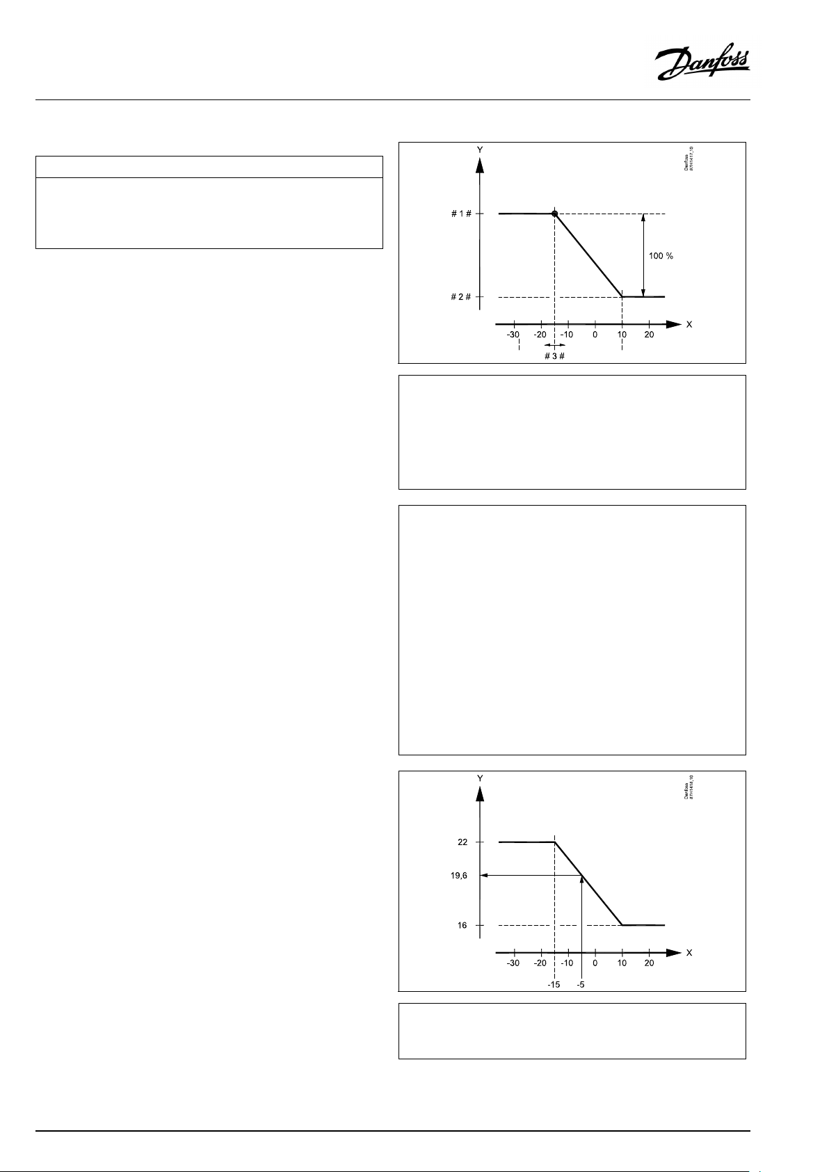
OperatingGuideECLComfort210/296/310,applicationA247/A347
MENU>Settings>Optimization
Autosaving(savingtemp.dependentonoutdoortemp.)
Belowthesetvaluefortheoutdoortemperature,thesavingtemperature
settinghasnoinfluence.Abovethesetvaluefortheoutdoortemperature,
thesavingtemperaturerelatestotheactualoutdoortemperature.The
functionisrelevantindistrictheatinginstallationsinordertoavoidabig
changeinthedesiredflowtemperatureafterasavingperiod.
SeeAppendix“ParameterIDoverview”
OFF:
Thesavingtemperaturedoesnotdependonthe
outdoortemperature;thereductionis100%.
Value:Thesavingtemperaturedependsontheoutdoor
temperature.Whentheoutdoortemperatureisabove
10°C,thereductionis100%.Thelowertheoutdoor
temperature,thelessthetemperaturereduction.
Belowthesetvalue,thesavingtemperaturesetting
hasnoinfluence.
Comforttemperature:
Thedesiredroomtemperaturein
Comfortmode
Savingtemperature:
ThedesiredroomtemperatureinSaving
mode
ThedesiredroomtemperaturesforComfortandSavingmodes
aresetinthedisplayoverviews.
1x011
=
X
Y
#1#
#2#
#3#
Example:
Actualoutdoortemperature(T.out):
DesiredroomtemperaturesettinginComfortmode:
DesiredroomtemperaturesettinginSavingmode:
Settingin‘Autosaving’:
Outdoortemperature(°C)
=
Desiredroomtemperature(°C)
=
Desiredroomtemperature(°C),Comfortmode
=
Desiredroomtemperature(°C),Savingmode
=
Autosavingtemperature(°C),ID11011
–5°C
22°C
16°C
–15°C
Theconditionfortheoutdoortemperatureinfluence:
T.out.influence=(10-T.out)/(10-setting)=
(10-(-5))/(10-(-15))=
15/25=0,6
ThecorrecteddesiredroomtemperatureinSavingmode:
T.room.ref.Saving+(T.out.influencex(T.room.ref.ComfortT.room.ref.Saving))
16+(0,6x(22-16))=19,6°C
=
X
Y
Outdoortemperature(°C)
=
Desiredroomtemperature(°C)
82|©Danfoss|2021.12
AQ192386469094en-010802
Page 83
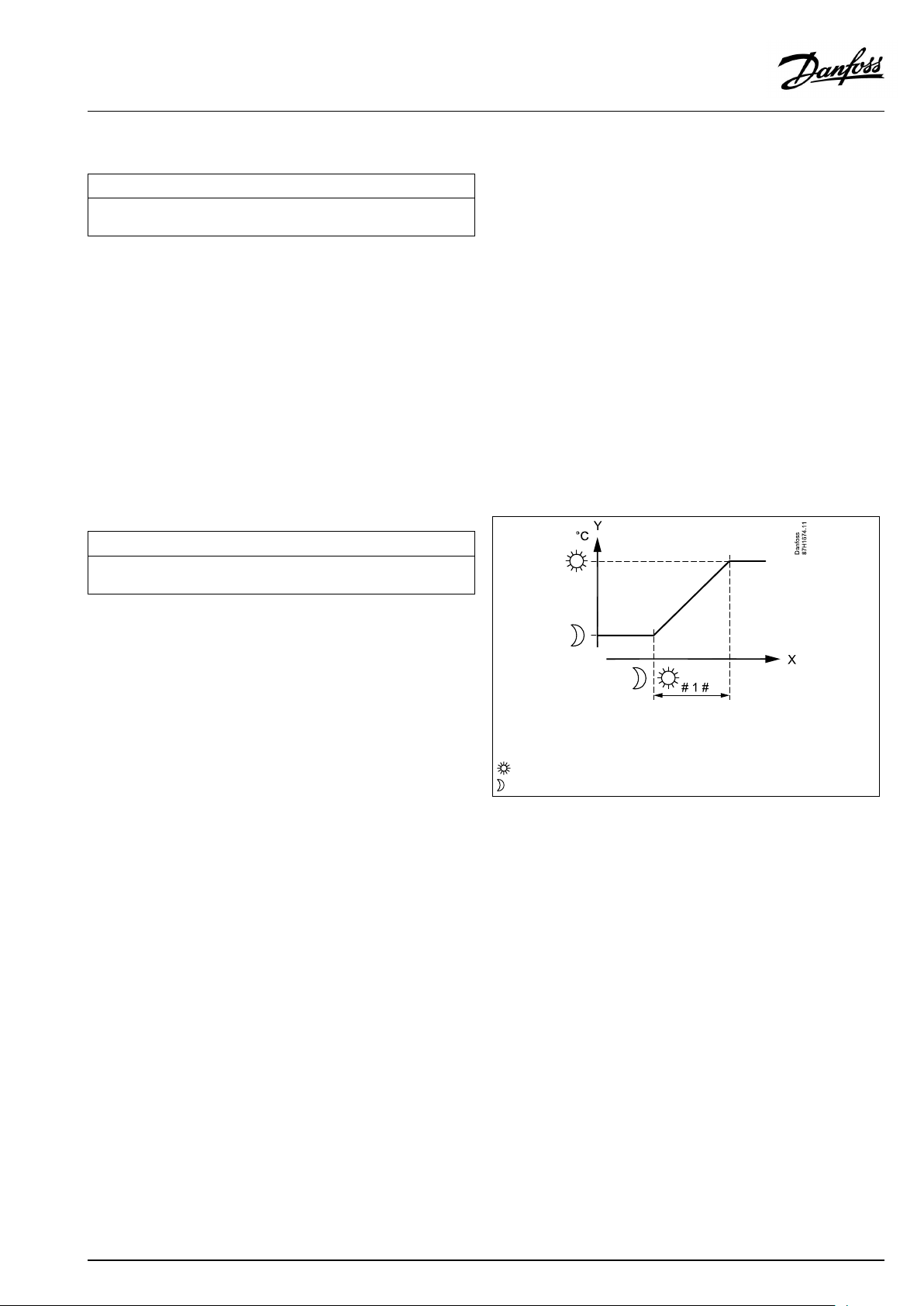
OperatingGuideECLComfort210/296/310,applicationA247/A347
MENU>Settings>Optimization
Boost
Shortenstheheating-upperiodbyincreasingthedesiredflowtemperature
bythepercentageyouset.
SeeAppendix“ParameterIDoverview”
OFF:
Value:
Theboostfunctionisnotactive.
Thedesiredflowtemperatureisincreasedtemporarily
withthesetpercentage.
Inordertoshortentheheating-upperiodafterasaving
temperatureperiod,thedesiredflowtemperaturecanbeincreased
temporarily(max.1hour).Atoptimizingtheboostisactiveinthe
optimizationperiod('Optimizer').
IfaroomtemperaturesensororanECA30/31isconnected,the
booststopswhentheroomtemperatureisreached.
MENU>Settings>Optimization
Ramp(referenceramping)
Thetime(minutes)inwhichthedesiredflowtemperatureincreases
graduallytoavoidloadpeaksintheheatsupply.
SeeAppendix“ParameterIDoverview”
1x012
1x013
OFF:
Value:
Therampingfunctionisnotactive.
Thedesiredflowtemperatureisincreasedgraduallywith
thesetminutes.
Inordertoavoidloadpeaksinthesupplynetwork,theflow
temperaturecanbesettoincreasegraduallyafteraperiodwith
savingtemperature.Thiscausesthevalvetoopengradually.
X
Y
#1#
=
Time
=
Desiredflowtemperature
=
Rampingtime
=
Comforttemperature
=
Savingtemperature
AQ192386469094en-010802
©Danfoss|2021.12|83
Page 84
OperatingGuideECLComfort210/296/310,applicationA247/A347
MENU>Settings>Optimization
Optimizer(optimizingtimeconstant)
Optimizesthestartandstoptimesforthecomforttemperatureperiodto
obtainthebestcomfortatthelowestenergyconsumption.
Thelowertheoutdoortemperature,theearliertheheatingcut-in.Thelower
theoutdoortemperature,thelatertheheatingcut-out.
Theoptimizedheatingcut-outtimecanbeautomaticordisabled.The
calculatedstartandstoptimesarebasedonthesettingoftheoptimizing
timeconstant.
SeeAppendix“ParameterIDoverview”
Adjusttheoptimizingtimeconstant.
Thevalueconsistsofatwodigitnumber.Thetwodigitshavethe
followingmeaning(digit1=TableI,digit2=TableII).
OFF:
Nooptimization.Theheatingstartsandstopsatthe
timessetintheschedule.
10...59:
SeetablesIandII.
TableI:
1x014
Systemtype
LeftdigitHeataccumulationofthe
building
Radiator
1-light
systems
2-medium
3-heavy
Floorheating
4-medium
systems
5-heavy
TableII:
RightdigitDimensioningtemperatureCapacity
-0-50°Clarge
-1
-45°C
-5
-25°C
normal
MENU>Settings>Optimization
Basedon(optimizationbasedonroom/outdoortemp.)
Theoptimizedstartandstoptimecanbebasedoneitherroomoroutdoor
temperature.
SeeAppendix“ParameterIDoverview”
OUT:
Optimizationbasedonoutdoortemperature.Usethis
settingiftheroomtemperatureisnotmeasured.
ROOM:
Optimizationbasedonroomtemperature,ifmeasured.
-9
Dimensioningtemperature:
Thelowestoutdoortemperature(usuallydeterminedbyyoursystem
designerinconnectionwiththedesignoftheheatingsystem)atwhich
theheatingsystemcanmaintainthedesignedroomtemperature.
Example
Thesystemtypeisradiator,andtheheataccumulationofthebuilding
ismedium.
Theleftdigitis2.
Thedimensioningtemperatureis-25°C,andthecapacityisnormal.
Therightdigitis5.
Result:
Thesettingistobechangedto25.
1x020
-5°C
small
84|©Danfoss|2021.12
AQ192386469094en-010802
Page 85
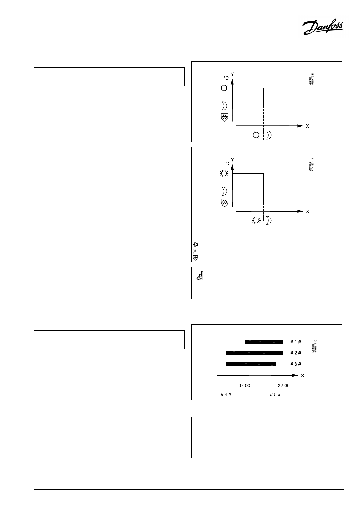
OperatingGuideECLComfort210/296/310,applicationA247/A347
MENU>Settings>Optimization
Totalstop
Decidewhetheryouwantatotalstopduringthesavingtemperatureperiod.
1x021
SeeAppendix“ParameterIDoverview”
OFF:
Nototalstop.Thedesiredflowtemperatureisreduced
accordingto:
•desiredroomtemperatureinsavingmode
•autosaving
ON:
Thedesiredflowtemperatureisloweredtothesetvalue
in‘Frostpr. ’Thecirculationpumpisstoppedbutfrost
protectionisstillactive,see'PfrostT' .
Totalstop=OFF
Totalstop=ON
X
Y
=
Time
=
Desiredflowtemperature
=
Comforttemperature
=
Savingtemperature
=
Frostprotection
MENU>Settings>Optimization
Pre-stop(optimizedstoptime)
Disabletheoptimizedstoptime.
SeeAppendix“ParameterIDoverview”
OFF:
ON:
Theoptimizedstoptimeisdisabled.
Theoptimizedstoptimeisenabled.
Themin.flowtemperaturelimitation('Temp.min.')isoverruledwhen
'Totalstop'isON.
1x026
Example:OptimizationofComfortfrom07:00-22:00
=
X
#1#
#2#
#3#
#4#
#5#
Time
=
Schedule
=
Prestop=OFF
=
Prestop=ON
=
Optimizedstart
=
Optimizedstop
AQ192386469094en-010802
©Danfoss|2021.12|85
Page 86
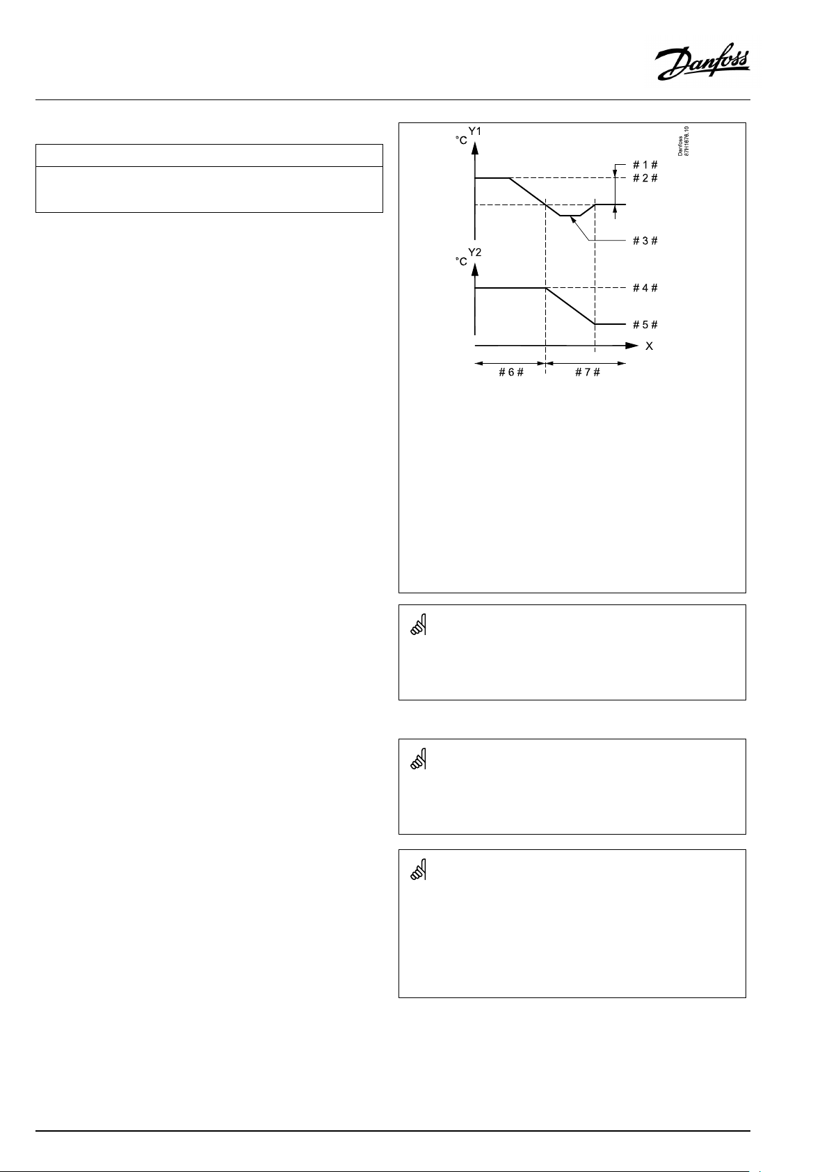
OperatingGuideECLComfort210/296/310,applicationA247/A347
MENU>Settings>Optimization
Paralleloperation
ChoosewhethertheheatingcircuitistooperateindependenceoftheDHW
circuit.Thisfunctionmightbeusefulifaninstallationhaslimitedpower
orflow.
SeeAppendix“ParameterIDoverview”
OFF:
Independentparalleloperation,i.e.theDHWand
theheatingcircuitsoperateindependentlyofeach
other.ItmakesnodifferencewhetherthedesiredDHW
temperaturecanbereachedornot.
Value:Dependentparalleloperation,i.e.thedesiredheating
temperaturedependsontheDHWdemand.Choose
howmuchtheDHWtemperaturecandropbeforethe
desiredheatingtemperaturehastobedecreased.
1x043
=
X
Y1
Y2
#1#
#2#
#3#
#4#
#5#
#6#
#7#
Time
=
Temperature
=
Temperature
=
Acceptabledeviation(Paralleloperation,1x043)
=
DesiredDHWtemperature
=
ActualDHWtemperature
=
Desiredheatingtemperature
=
Reducedheatingtemperature
=
100%paralleloperation
=
Paralleloperationwithdecreasedheatingtemperature
IftheactualDHWtemperaturedeviatesmorethanthesetvalue,the
gearmotorM2intheheatingcircuitwillgraduallyclosetosuchan
extentthattheDHWtemperaturestabilizesatthelowestacceptable
value.
IncasetheParalleloperationisactive(atoolowDHWtemperature
andthereforeareducedheatingcircuittemperature),aslave's
temperaturedemandwillnotchangethedesiredflowtemperaturein
theheatingcircuit.
Whendependentparalleloperationisinfunction:
•Desiredflowtemperaturefortheheatingcircuitwillbeminimum
limited,when"Priorityforreturntemperature"(ID1x085)isset
toOFF.
•Desiredflowtemperaturefortheheatingcircuitwillnotbe
minimumlimited,when"Priorityforreturntemperature"
(ID1x085)issettoON.
86|©Danfoss|2021.12
AQ192386469094en-010802
Page 87
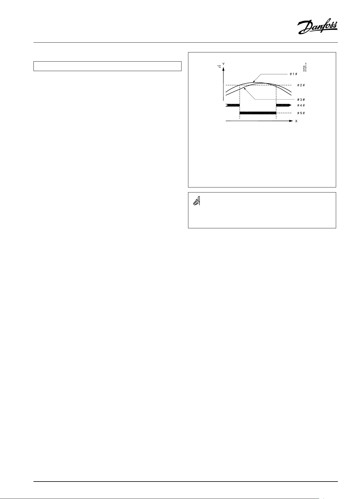
OperatingGuideECLComfort210/296/310,applicationA247/A347
MENU>Settings>Optimization
Summer,cut-out(limitforheatingcut-out)
1x179
SeeAppendix“ParameterIDoverview”
TheheatingcanbeswitchedOFFwhentheoutdoortemperatureis
higherthanthesetvalue.Thevalveclosesandafterthepost-run
time,theheatingcirculationpumpstops.‘Temp.min.’willbe
overruled.
TheheatingsystemswitchesONagainwhentheoutdoor
temperatureandtheaccumulated(filtered)outdoortemperature
becomelowerthanthesetlimit.
Thisfunctioncansaveenergy.
Setthevalueforoutdoortemperatureatwhichyouwantthe
heatingsystemtoswitchOFF .
Summer,cut-out
=
X
Y
#1#
#2#
#3#
#4#
#5#
Time
=
Temperature
=
Actualoutdoortemperature
=
Cut-outtemperature(1x179)
=
Accummulated(filtered)outdoortemperature
=
Heatingenabled
=
Heatingdisabled
Theheatingcut-outisonlyactivewhenthecontrollermodeisin
scheduledoperation.Whenthecut-outvalueissettoOFF,thereis
noheatingcut-out.
AQ192386469094en-010802
©Danfoss|2021.12|87
Page 88

OperatingGuideECLComfort210/296/310,applicationA247/A347
5.7Controlparameters
Controlofvalves
Themotorizedcontrolvalvesarecontrolledbymeansof3-point
controlsignal.
Valvecontrol:
Themotorizedcontrolvalveisopenedgraduallywhentheflow
temperatureislowerthanthedesiredflowtemperatureandvice
versa.
Thewaterflowthroughthecontrolvalveismanagedbymeans
ofanelectricactuator.Thecombination"actuator"and"control
valve"isalsocalledmotorizedcontrolvalve.Theactuatorcanin
thiswaygraduallyincreaseordecreasetheflowinordertochange
thesuppliedenergy.Differenttypesofactuatorsareavailable.
3-pointcontrolledactuator:
Theelectricactuatorcontainsareversiblegear-motor.Electric
"open"and"close"signalscomefromtheelectronicoutputsofthe
ECLComfortcontrollerinordertomanagethecontrolvalve.The
signalsareintheECLComfortcontrollerexpressedas"Arrow-up"
(open)and"Arrow-down"(close)anddisplayedatthevalvesymbol.
Whentheflowtemperature(forexampleatS3)islowerthanthe
desiredflowtemperature,shortopen-signalscomefromtheECL
Comfortcontrollerinordertograduallyincreasetheflow.Bythis,
theflowtemperaturewillalignwiththedesiredtemperature.
Oppositely,whentheflowtemperatureishigherthanthedesired
flowtemperature,shortclose-signalscomefromtheECLComfort
controllerinordertograduallyreducetheflow.Again,theflow
temperaturealignswiththedesiredtemperature.
Neitheropen-signalsnorclose-signalswillcomeaslongastheflow
temperaturecorrespondstothedesiredtemperature.
88|©Danfoss|2021.12
AQ192386469094en-010802
Page 89
OperatingGuideECLComfort210/296/310,applicationA247/A347
Thermo-hydraulicactuator,ABV
Danfossthermo-actuatortypeABVisaslowactingvalveactuator.
InsidetheABVanelectricheatcoilwillheatathermostaticelement
whenanelectricsignalisapplied.Whenheatingthethermostatic
elementitexpandsinordertomanagethecontrolvalve.
Twobasictypesareavailable:ABVNC(NormalClosed)andABVNO
(normalopen).Forexample,ABVNCkeepsa2-portcontrolvalve
closedwhennoopen-signalsareapplied.
Electricopen-signalscomefromtheelectronicoutputoftheECL
Comfortcontrollerinordertomanagethecontrolvalve.When
open-signalsareappliedtotheABVNC,thevalvegraduallyopens.
Open-signalsareintheECLComfortcontrollerexpressedas
"Arrow-up"(open)anddisplayedatthevalvesymbol.
Whentheflowtemperature(forexampleatS3)islowerthanthe
desiredflowtemperature,relativelylongopen-signalscomefrom
theECLComfortcontrollerinordertoincreasetheflow.Bythis,
theflowtemperaturewillovertimebealignedwiththedesired
temperature.
Oppositely,whentheflowtemperatureishigherthanthedesired
flowtemperature,relativelyshortopen-signalscomefromtheECL
Comfortcontrollerinordertoreducetheflow.Again,theflow
temperaturealigns,overtime,withthedesiredtemperature.
ThecontroloftheDanfossthermo-actuatortypeABVusesaunique
designedalgorithmandisbasedonthePWMprinciple(Pulse
WidthModulation),wherethedurationofthepulsedetermines
themanagementofthecontrolvalve.Thepulsesarerepeated
each10sec.
Aslongastheflowtemperaturecorrespondstothedesired
temperature,thedurationoftheopen-signalswillremainconstant.
ParametersindicatedwithanIDno.like"1x607"meanauniversal
parameter.
xstandsforcircuit/parametergroup.
MENU>Settings>Controlparameters
Actuator
ABV/GEAR
1x024
GEAR
Selectionofvalveactuatortype.
Whenselecting"ABV",thecontrolparameters:
•Motorprotection(ID1x174)
ABV:
GEAR:
AQ192386469094en-010802
DanfosstypeABV(thermoactuator).
Gearmotorbasedactuator.
•Xp(ID1x184)
•Tn(ID1x185)
•Mrun(ID1x186)
•Nz(ID1x187)
•Min.act.time(ID1x189)
arenotconsidered.
©Danfoss|2021.12|89
Page 90

OperatingGuideECLComfort210/296/310,applicationA247/A347
MENU>Settings>Controlparameters
Motorpr.(motorprotection)
Preventsthecontrollerfromunstabletemperaturecontrol(andresulting
actuatoroscillations).Thiscanoccuratverylowload.Themotorprotection
increasesthelifetimeofallinvolvedcomponents.
SeeAppendix“ParameterIDoverview”
OFF:
Value:
Motorprotectionisnotactivated.
Motorprotectionisactivatedafterthesetactivation
delayinminutes.
MENU>Settings>Controlparameters
Xp(proportionalband)
SeeAppendix“ParameterIDoverview”
Settheproportionalband.Ahighervaluewillresultinastablebut
slowcontroloftheflowtemperature.
MENU>Settings>Controlparameters
Xpactual
‘Xpactual’istheread-outoftheactualXp(proportionalband)basedon
thesupplytemperature.Xpisdeterminedbysettingsrelatedtothesupply
temperature.Typically,thehigherthesupplytemperature,thehighertheXp
mustbeinordertoachieveastabletemperaturecontrol.
1x174
Recommendedforductsystemswithvariableload.
1x184
Xpsettingrange:
5...250K
Fixedsupplytemperaturesettings:65°Cand90°C
Factorysettings:
(65,40)and(90,120)
Thismeansthatthe‘Xp’is40Kat65°Csupplytemperature,and
‘Xp’is120Kat90°C.
SetthedesiredXpvaluesatthetwofixedsupplytemperatures.
Ifthesupplytemperatureisnotmeasured(thesupplytemperature
sensorisnotconnected),theXpvalueatthesetting65°Cisused.
MENU>Settings>Controlparameters
Tn(integrationtimeconstant)
1x185
SeeAppendix“ParameterIDoverview”
Setahighintegrationtimeconstant(inseconds)toobtainaslow
butstablereactiontodeviations.
Alowintegrationtimeconstantwillmakethecontrollerreactfast
butwithlessstability.
90|©Danfoss|2021.12
AQ192386469094en-010802
Page 91

OperatingGuideECLComfort210/296/310,applicationA247/A347
MENU>Settings>Controlparameters
Mrun(runningtimeofthemotorizedcontrolvalve)
‘Mrun’isthetimeinsecondsittakesthecontrolledcomponenttomove
fromfullyclosedtofullyopenposition.
SeeAppendix“ParameterIDoverview”
Setthe‘Mrun’accordingtotheexamplesormeasuretherunning
timebymeansofastopwatch.
MENU>Settings>Controlparameters
1x186
Howtocalculatetherunningtimeofamotorizedcontrolvalve
Therunningtimeofthemotorizedcontrolvalveiscalculatedusing
thefollowingmethods:
Seatedvalves
Runningtime=
Example:
Rotatingvalves
Runningtime=
Example:90degr.x2sec./degr.=180sec.
Valvestroke(mm)xactuatorspeed(sec./mm)
5.0mmx15sec./mm=75sec.
Turningdegreesxactuatorspeed(sec./degr.)
Nz(neutralzone)
Whentheactualflowtemperatureiswithintheneutralzone,thecontroller
doesnotactivatethemotorizedcontrolvalve.
SeeAppendix“ParameterIDoverview”
Settheacceptableflowtemperaturedeviation.
Settheneutralzonetoahighvalueifyoucanacceptahigh
variationinflowtemperature.
MENU>Settings>Controlparameters
Min.act.time(min.activationtimegearmotor)
Themin.pulseperiodof20ms(milliseconds)foractivationofthegear
motor.
SeeAppendix“ParameterIDoverview”
1x187
Theneutralzoneissymmetricalaroundthedesiredflowtemperature
value,i.e.halfthevalueisaboveandhalfthevalueisbelowthis
temperature.
SettingexampleValuex20ms
1x189
240ms
10200ms
501000ms
Thesettingshouldbekeptashighasacceptabletoincreasethe
lifetimeoftheactuator(gearmotor).
AQ192386469094en-010802
©Danfoss|2021.12|91
Page 92

OperatingGuideECLComfort210/296/310,applicationA247/A347
IfyouwanttotunethePIregulationprecisely,youcanusethefollowingmethod:
•Setthe‘Tn’(integrationtimeconstant)toitsmax.value(999sec.).
•Decreasethevalueforthe‘Xp’(proportionalband)untilthesystemstartshunting(i.e.getsunstable)withaconstantamplitude(it
mightbenecessarytoforcethesystembysettinganextremelowvalue).
•Findthecriticaltimeperiodonthetemperaturerecorderoruseastopwatch.
Temp.
Thiscriticaltimeperiodwillbecharacteristicforthesystem,andyoucanevaluatethesettingsfromthiscriticalperiod.
‘Tn’=
0.85xcriticaltimeperiod
‘Xp’=
2.2xproportionalbandvalueinthecriticaltimeperiod
Iftheregulationseemstobetooslow,youcandecreasetheproportionalbandvalueby10%.Makesurethereisaconsumption
whenyousettheparameters.
Criticaltimeperiod
Time
92|©Danfoss|2021.12
AQ192386469094en-010802
Page 93

OperatingGuideECLComfort210/296/310,applicationA247/A347
5.8Application
Thesection"Application"describesspecificapplicationrelated
issues.
Someoftheparameterdescriptionsareuniversalfordifferent
applicationkeys.
PumpP2istheDHWpump.Post-runtimeissetin"DHWP
post-run"(ID1x041).
PumpP4istheDHWchargingpump.Post-runtimeissetin"Char.
Ppost-run"(ID1x042).
ParametersindicatedwithanIDno.like"1x607"meanauniversal
parameter.
xstandsforcircuit/parametergroup.
MENU>Settings>Application
ECAaddr.(ECAaddress,choiceofRemoteControlUnit)
Decidestheroomtemperaturesignaltransferandcommunicationwiththe
RemoteControlUnit.
SeeAppendix“ParameterIDoverview”
OFF:
NoRemoteControlUnit.Onlyroomtemperaturesensor,
ifany.
A:
B:
RemoteControlUnitECA30/31withaddressA.
RemoteControlUnitECA30/31withaddressB.
1x010
TheRemoteControlUnitmustbesetaccordingly(AorB).
AQ192386469094en-010802
©Danfoss|2021.12|93
Page 94

OperatingGuideECLComfort210/296/310,applicationA247/A347
MENU>Settings>Application
Demandoffset
Thedesiredflowtemperatureinheatingcircuit1orDHW-circuit2canbe
influencedbythedemandforadesiredflowtemperaturefromanother
controller(slave)oranothercircuit.
SeeAppendix“ParameterIDoverview”
OFF:
Thedesiredflowtemperatureincircuit1orcircuit2is
notinfluencedbythedemandofanyothercontroller
(slaveorcircuit2).
Value:
Thedesiredflowtemperatureisincreasedbytheset
valuein‘Demandoffset’ ,ifthedemandoftheslave/
circuit1orcircuit2ishigher.
Heatingapplication
1x017
=
X
Y
#1#
#2#
#3#
Time
=
Desiredflowtemperatures
=
Demandoffset
=
Desiredflowtemperature,master
=
Desiredflowtemperature,slave
'Demandoffset'withavalueistobeusedintheMastercontrolleronly.
Ifbothcircuitsaresetwithavaluein"Demandoffset"thefunctionality
isdisabled.
Thefunctionof‘Demandoffset’cancompensateforheatlosses
betweenmasterandslavecontrolledsystems.
Whensetting"Demandoffset"toavalue,thereturntemperature
limitationwillreactaccordingtothehighestlimitationvalue(Heating
/DHW).
94|©Danfoss|2021.12
AQ192386469094en-010802
Page 95

OperatingGuideECLComfort210/296/310,applicationA247/A347
MENU>Settings>Application
Pexercise(pumpexercise)
Exercisesthepumptoavoidblockinginperiodswithoutheatdemand.
SeeAppendix“ParameterIDoverview”
OFF:
ON:
Thepumpexerciseisnotactive.
ThepumpisswitchedONfor1minuteeverythirddayat
noon(12:14hours).
MENU>Settings>Application
Mexercise(valveexercise)
Exercisesthevalvetoavoidblockinginperiodswithoutheatdemand.
SeeAppendix“ParameterIDoverview”
OFF:
ON:
Thevalveexerciseisnotactive.
Thevalveopensfor7minutesandclosesfor7minutes
everythirddayatnoon(12:00hours).
MENU>Settings>Application
1x022
1x023
Ppost-run
Heatingapplications:
ThecirculationpumpintheheatingcircuitcanbeONforanumberof
minutes(m)afterheatingstop.Heatingstopiswhenthedesiredflow
temperaturegetslowerthanthesettingin'PheatT'(IDno.1x078).
Coolingapplications:
ThecirculationpumpinthecoolingcircuitcanbeONforanumberof
minutes(m)aftercoolingstop.Coolingstopiswhenthedesiredflow
temperaturegetshigherthanthesettingin'PcoolT'(IDno.1x070).
ThisPpost-runfunctioncanutilizetheremainingenergyinforexamplea
heatexchanger.
SeeAppendix“ParameterIDoverview”
0:
Thecirculationpumpstopsimmediatelyafterheating
orcoolingstop.
Value:
ThecirculationpumpisONforthesettimeafterheating
orcoolingstop.
MENU>Settings>Application
DHWPpost-run(DHWpump,post-run)
SettheDHWpumppost-runtime(minutes).TheDHWpumpcancontinue
tobeswitchedONaftertheDHWheatingprocedureinordertoutilizethe
remainingheatintheheatexchanger/boiler.
1x040
1x041
SeeAppendix“ParameterIDoverview”
Value:
Setthenumberofminutesforthepost-run.
AQ192386469094en-010802
©Danfoss|2021.12|95
Page 96

OperatingGuideECLComfort210/296/310,applicationA247/A347
MENU>Settings>Application
Char.Ppost-run(DHWchargingpump,post-run)
SettheDHWchargingpumppost-runtime(minutes).TheDHWcharging
pumpcancontinuetobeswitchedONaftertheDHWheatingprocedurein
ordertoutilizetheremainingheatintheheatexchanger.
SeeAppendix“ParameterIDoverview”
Value:
Setthenumberofminutesforthepost-run.
MENU>Settings>Application
Max.DHWtime
SetthemaxDHWheatingtime(minutes).WhenDHWheatingisactiveand
theset'Max.DHWtime'expires,DHWheatingisdeactivated.
SeeAppendix“ParameterIDoverview”
OFF:
IftheDHWtemperatureislowerthantheDHWcharging
cut-intemperature,theDHWchargingremainsactive
forunlimitedperiodoftime.IftheDHWtemperatureis
higherthantheDHWchargingcut-intemperature,the
chargingisdeactivatedafter35minutes.
Value:
TheDHWheating/chargingisdeactivatedwhentheset
'Max.DHWtime'(inminutes)expires.
1x042
1x044
MENU>Settings>Application
DHWdeact.time(DHWdeactivationtime)
Setthetime(minutes)thatmustelapseafteraDHWheatingperiodbeforea
newDHWheatingperiodcanbestarted.
1x045
SeeAppendix“ParameterIDoverview”
Value:WhentheDHWheating/chargingtimehasreachedits
maximum,DHWcanonlybeheated/chargedagain
afterthesetdeactivationtime(inminutes)hasexpired.
96|©Danfoss|2021.12
AQ192386469094en-010802
Page 97
OperatingGuideECLComfort210/296/310,applicationA247/A347
MENU>Settings>Application
Pdemand
Thecirculationpumpinthemastercircuitcanbecontrolledinrelationto
themastercircuit'sdemandorslavecircuit'sdemand.
SeeAppendix“ParameterIDoverview”
Heatingapplications:
OFF:
ThecirculationpumpisONwhenthedesiredflow
temperatureintheheatingcircuitishigherthanthe
valuesetin'PheatT'.
ON:
ThecirculationpumpisONwhenthedesiredflow
temperaturefromslavesishigherthanthevaluesetin
'PheatT'.
Coolingapplications:
OFF:
ThecirculationpumpisONwhenthedesiredflow
temperatureinthecoolingcircuitislowerthanthevalue
setin'PcoolT'.
ON:
ThecirculationpumpisONwhenthedesiredflow
temperaturefromslavesislowerthanthevaluesetin
'PcoolT'.
MENU>Settings>Application
1x050
Thecirculationpumpisalwayscontrolledaccordingtofrostprotection
conditions.
DHWpriority(closedvalve/normaloperation)
Theheatingcircuitcanbeclosedwhenthecontrolleractsasslaveandwhen
DHWheating/chargingisactiveinthemaster.
SeeAppendix“ParameterIDoverview”
OFF:
Theflowtemperaturecontrolremainsunchanged
duringactiveDHWheating/charginginthemaster
controller.
ON:
Thevalveintheheatingcircuitisclosed*duringactive
DHWheating/charginginthemastercontroller.
*Thedesiredflowtemperatureissettothevaluesetin
‘Frostpr.T’
MENU>Settings>Application
Cont.Tcontrol
ThedesiredDHWheating/chargingtemperaturecanbeloweredwhenthe
DHWheating/chargingprocedurehaselapsed.
SeeAppendix“ParameterIDoverview”
OFF:
Thedesiredheating/chargingtemperatureislowered
to10°C.Typically,theDHWiscirculatedthroughthe
DHWtank.
ON:
Thedesiredheating/chargingtemperatureislowered
tothedesiredDHWtemperature.Typically,theDHW
iscirculatedthroughtheheatexchangerinorderto
compensatefortheheatlossintheDHWcirculation
pipe.
1x052
Thissettingmustbeconsideredifthiscontrollerisaslave.
1x054
AQ192386469094en-010802
©Danfoss|2021.12|97
Page 98
OperatingGuideECLComfort210/296/310,applicationA247/A347
MENU>Settings>Application
Circ.Ppriority
ChoosewhethertheDHWcirculationpumpshouldbeONduringDHW
heating.
SeeAppendix“ParameterIDoverview”
OFF:
TheDHWcirculationpumpisswitchedOFFduringDHW
heating.
ON:
TheDHWcirculationpumpisnotswitchedOFFduring
DHWheating.
MENU>Settings>Application
Pchargedelay(Chargingpump,delayedstart)
ConditionsforswitchingtheDHWheating/chargingpumpONatDHW
heating/chargingdemand.
Correctsettingcanavoiddischarging.
SeeAppendix“ParameterIDoverview”
OFF:
DHWheating/chargingpumpisswitchedONwhen
DHWheating/chargingtemperatureisOK.
0:
Value:
DHWheating/chargingpumpisswitchedON.
DHWheating/chargingpumpisswitchedONafterthe
setnumberofminutes.
1x055
Whenthe'Circ.Ppriority'issettoOFF ,theschedulefortheDHW
circulationpumpisoverruled.
1x059
Whenthesetting"OFF"isselected,thetemperaturesensorforDHW
heating/chargingmustbeplacedintheheat-exchanger.
MENU>Settings>Application
Circ.PfrostT
SettheoutdoortemperaturevalueatwhichtheDHWcirculationpumpisto
beactivetoprotecttheDHWcircuitagainstfrost.
SeeAppendix“ParameterIDoverview”
OFF:
Value:
TheDHWcirculationpumpisnotactive.
TheDHWcirculationpumpisactivewhentheoutdoor
temperatureislowerthanthesetvalue.
MENU>Settings>Application
PfrostT(circulationpump,frostprotectiontemp.)
Frostprotection,basedontheoutdoortemperature.
Whentheoutdoortemperaturegetsbelowthesettemperaturevaluein‘P
frostT’ ,thecontrollerautomaticallyswitchesONthecirculationpump(for
exampleP1orX3)toprotectthesystem.
SeeAppendix“ParameterIDoverview”
OFF:
Value:
Nofrostprotection.
CirculationpumpisONwhentheoutdoortemperature
isbelowthesetvalue.
1x076
1x077
Undernormalconditions,yoursystemisnotfrostprotectedifyour
settingisbelow0°CorOFF.
Forwater-basedsystems,asettingof2°Cisrecommended.
Iftheoutdoortemperaturesensorisnotconnectedandthefactory
settinghasnotbeenchangedto'OFF' ,thecirculationpumpisalways
ON.
98|©Danfoss|2021.12
AQ192386469094en-010802
Page 99
OperatingGuideECLComfort210/296/310,applicationA247/A347
MENU>Settings>Application
PheatT(heatdemand)
Whenthedesiredflowtemperatureisabovethesettemperaturein‘PheatT’ ,
thecontrollerautomaticallyswitchesONthecirculationpump.
1x078
SeeAppendix“ParameterIDoverview”
Value:ThecirculationpumpisswitchedONwhenthedesired
flowtemperatureisabovethesetvalue.
MENU>Settings>Application
Frostpr .T(frostprotectiontemp.)
SetthedesiredflowtemperatureattemperaturesensorS3toprotectthe
systemagainstfrost(atheatingcut-out,totalstopetc.).
WhenthetemperatureatS3getslowerthanthesetting,themotorized
controlvalveopensgradually.
1x093
SeeAppendix“ParameterIDoverview”
Thevalveisfullyclosedaslongasthepumpisnotswitchedon.
Thefrostprotectiontemperaturecanalsobesetinyourfavorite
displaywhenthemodeselectorisinfrostprotectionmode.
AQ192386469094en-010802
©Danfoss|2021.12|99
Page 100

OperatingGuideECLComfort210/296/310,applicationA247/A347
Overridemodefunctions:
ThefollowingsettingsdescribethefunctioningeneralfortheECL
Comfort210/296/310series.Theexplainedmodesaretypical
andnotapplicationrelated.Theymightdifferfromtheoverride
modesinyourapplication.
MENU>Settings>Application
Ext.input(externaloverride)
Choosetheinputfor'Ext.input'(externaloverride).Bymeansofaswitch
thecontrollercanbeoverriddento‘Comfort’,'Saving' ,'Frostprotection'or
'Constanttemperature'mode.
1x141
SeeAppendix“ParameterIDoverview”
OFF:
S1...S16:
Noinputshavebeenselectedforexternaloverride.
Inputselectedforexternaloverride.
IfS1...S6ischosenasoverrideinput,theoverrideswitchmusthave
gold-platedcontacts.
IfS7...S16ischosenasoverrideinput,theoverrideswitchcanbea
standardcontact.
Seethedrawingsforconnectionexamplesofoverrideswitchand
overriderelaytoinputS8.
S7...S16arerecommendedforoverrideswitch.
Example:Connectionofanoverrideswitch
Example:Connectionofanoverriderelay
IfECA32ismounted,alsoS11...S16canbeused.
IfECA35ismounted,alsoS11orS12canbeused.
Chooseonlyanunusedinputforoverride.Ifanalreadyusedinputis
appliedforoverride,thefunctionalityofthisinputisalsoneglected.
Seealso‘Ext.mode’.
100|©Danfoss|2021.12
AQ192386469094en-010802
 Loading...