

Page 1
OperatingGuide
ECLComfort310,applicationA333
1.0TableofContents
1.0TableofContents...............................................1
1.1Importantsafetyandproductinformation.....................2
2.0Installation........................................................5
2.1Beforeyoustart.....................................................5
2.2Identifyingthesystemtype......................................10
2.3Mounting...........................................................15
2.4Placingthetemperaturesensors................................18
2.5Electricalconnections.............................................20
2.6InsertingtheECLApplicationKey..............................51
2.7Checklist............................................................58
2.8Navigation,ECLApplicationKeyA333.........................59
3.0Dailyuse.........................................................64
3.1Howtonavigate...................................................64
3.2Understandingthecontrollerdisplay..........................65
3.3Ageneraloverview:Whatdothesymbolsmean?...........68
3.4Monitoringtemperaturesandsystem
components........................................................69
3.5Influenceoverview................................................70
3.6Manualcontrol.....................................................71
3.7Schedule............................................................72
4.0Settingsoverview............................................73
5.0Settings...........................................................76
5.1IntroductiontoSettings..........................................76
5.2Flowtemperature..................................................77
5.3Returnlimit.........................................................79
5.4Flow/powerlimit.................................................82
5.5Optimization........................................................85
5.6Controlparameters1..............................................90
5.7Controlparameters,refillpump(s)..............................95
5.8Controlparameters,circulationpump(s)....................100
5.9Pumpcontrol.....................................................103
5.10Refillwater........................................................106
5.11Refilltank..........................................................113
5.12Application.......................................................116
5.13Watermeter......................................................120
5.14Flowmeter........................................................121
5.15S7,S8,S9,S10pressure.........................................124
5.16Alarm..............................................................127
6.0Commoncontrollersettings............................132
6.1Introductionto‘Commoncontrollersettings’..............132
6.2Time&Date.......................................................133
6.3Holiday............................................................134
6.4Inputoverview...................................................136
6.5Log.................................................................137
6.6Outputoverride..................................................138
6.7Keyfunctions.....................................................139
6.8System.............................................................141
7.0Miscellaneous................................................148
7.1ECA30/31setupprocedures.................................148
7.2Overridefunction................................................156
7.3Severalcontrollersinthesamesystem......................159
7.4Frequentlyaskedquestions....................................162
7.5Definitions........................................................165
7.6Type(ID6001),overview.......................................169
7.7Automatic/manualupdateoffirmware.....................170
7.8ParameterIDoverview..........................................171
©Danfoss|2021.04AQ076586461441en-010401|1
Page 2
OperatingGuideECLComfort310,applicationA333
1.1Importantsafetyandproductinformation
1.1.1Importantsafetyandproductinformation
ThisInstallationGuideisassociatedwithECLApplicationKeyA333
(ordercodeno.087H3818).
ThefunctionsarerealizedinECLComfort310foradvanced
solutions,e.g.M-bus,ModbusandEthernet(Internet)
communication.
TheapplicationA333complieswithECLComfortcontrollers310as
ofsoftwareversion1.11(visibleatstart-upofthecontrollerandin
‘Commoncontrollersettings’in‘System’).
TheapplicationA333workswiththeInternalI/OmoduleECA32
(ordercodeno.087H3202).
AdditionaldocumentationforECLComfort310,modulesand
accessoriesisavailableonwww.ecl.doc.danfoss.com.
Applicationkeysmightbereleasedbeforealldisplaytextsare
translated.InthiscasethetextisinEnglish.
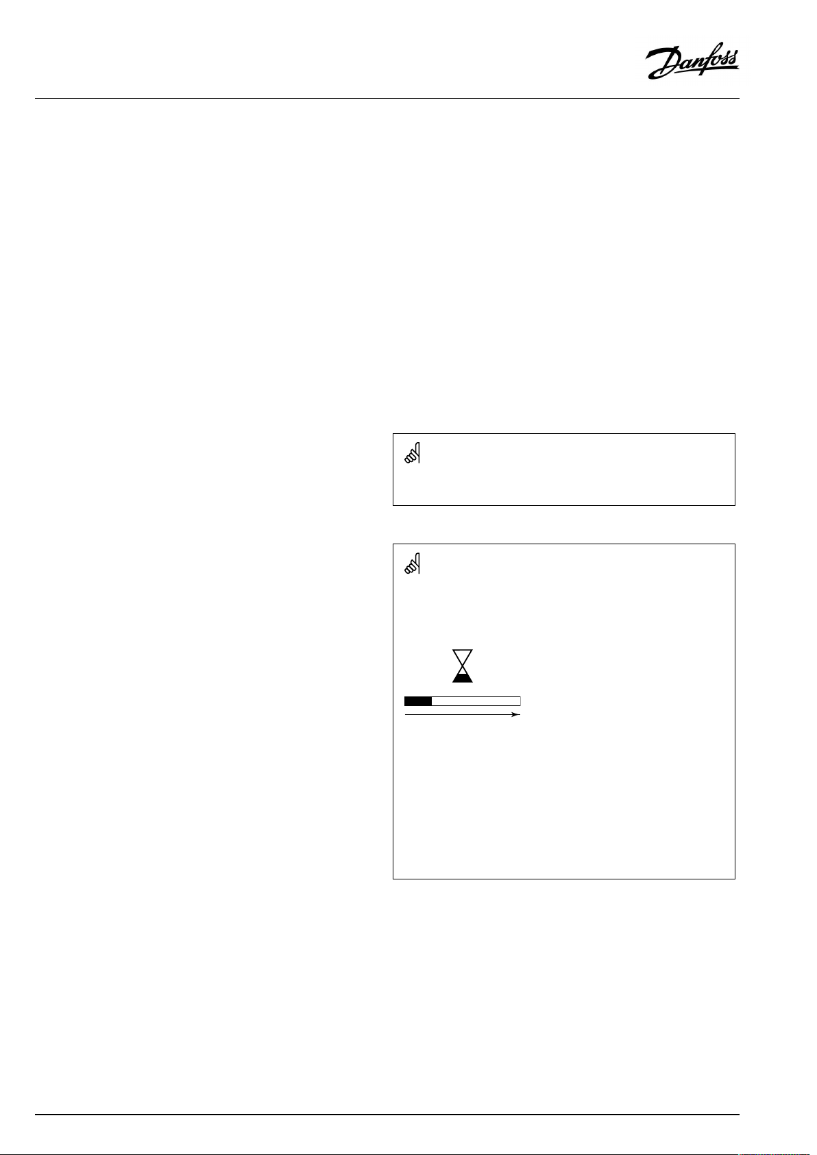
Automaticupdateofcontrollersoftware(firmware):
Thesoftwareofthecontrollerisupdatedautomaticallywhenthekey
isinserted(asofcontrollerversion1.11(ECL210/310)andversion
1.58(ECL296)).Thefollowinganimationwillbeshownwhenthe
softwareisbeingupdated:
Progressbar
Duringupdate:
•DonotremovetheKEY
Ifthekeyisremovedbeforethehour-glassisshown,youhave
tostartafresh.
•Donotdisconnectthepower
Ifthepowerisinterruptedwhenthehour-glassisshown,the
controllerwillnotwork.
•Manualupdateofcontrollersoftware(firmware):
Seethesection"Automatic/manualupdateoffirmware"
2|©Danfoss|2021.04
AQ076586461441en-010401
Page 3
OperatingGuideECLComfort310,applicationA333
SafetyNote
Toavoidinjuryofpersonsanddamagestothedevice,itisabsolutely
necessarytoreadandobservetheseinstructionscarefully.
Necessaryassembly,start-up,andmaintenanceworkmustbe
performedbyqualifiedandauthorizedpersonnelonly.
Locallegislationsmustberespected.Thiscomprisesalsocable
dimensionsandtypeofisolation(doubleisolatedat230V).
AfusefortheECLComfortinstallationismax.10Atypically.
TheambienttemperaturerangesforECLComfortinoperationare:
ECLComfort210/310:0-55°C
ECLComfort296:0-45°C.
Exceedingthetemperaturerangecanresultinmalfunctions.
Installationmustbeavoidedifthereisariskforcondensation(dew).
Thewarningsignisusedtoemphasizespecialconditionsthatshould
betakenintoconsideration.
Thissymbolindicatesthatthisparticularpieceofinformationshould
bereadwithspecialattention.
AsthisOperatingGuidecoversseveralsystemtypes,specialsystem
settingswillbemarkedwithasystemtype.Allsystemtypesareshown
inthechapter:'Identifyingyoursystemtype'.
°C(degreesCelsius)isameasuredtemperaturevaluewhereasK
(Kelvin)oftenisusedfortemperaturedifferences.
TheIDno.isuniquefortheselectedparameter.
ExampleFirstdigitSeconddigitLastthreedigits
1117411174
-
Circuit1Parameterno.
12174
IfanIDdescriptionismentionedmorethanonce,itmeansthatthere
arespecialsettingsforoneormoresystemtypes.Itwillbemarked
withthesystemtypeinquestion(e.g.12174-A266.9).
1
-
2
Circuit2Parameterno.
AQ076586461441en-010401
174
©Danfoss|2021.04|3
Page 4
OperatingGuideECLComfort310,applicationA333
ParametersindicatedwithanIDno.like"1x607"meanauniversal
parameter.
xstandsforcircuit/parametergroup.
DisposalNote
Thissymbolontheproductindicatesthatitmaynot
bedisposedofashouseholdwaste.
Itmustbehandedovertotheapplicabletake-back
schemefortherecyclingofelectricalandelectronic
equipment.
•Disposeoftheproductthroughchannelsprovided
forthispurpose.
•Complywithalllocalandcurrentlyapplicablelaws
andregulations.
4|©Danfoss|2021.04
AQ076586461441en-010401
Page 5
OperatingGuideECLComfort310,applicationA333
2.0Installation
2.1Beforeyoustart
TheA333applicationkeycontains3subtypes:A333.1,A333.2
andA333.3whicharealmostidentical.
Differentandextrafunctionsaredescribedadditionally.
TheapplicationA333.1isveryflexible.
Thesearethebasicprinciples:
Typically,theflowtemperatureisadjustedaccordingtoyour
requirements.
TheflowtemperaturesensorS3isthemostimportantsensor.The
desiredflowtemperatureatS3iscalculatedintheECLcontroller,
basedontheoutdoortemperature(S1)andthedesiredroom
temperature.Thelowertheoutdoortemperature,thehigherthe
desiredflowtemperature.
Bymeansofaweekschedule(upto3'Comfort'periods/day),the
heatingcircuitcanbein'Comfort'or'Saving'mode(twodifferent
temperaturevaluesforthedesiredroomtemperature).
InSavingmodetheheatingcanbereducedorswitchedofftotally.
ThemotorizedcontrolvalveM1isopenedgraduallywhentheflow
temperatureS3islowerthanthedesiredflowtemperatureand
viceversa.
Thereturntemperature(S5)canbelimited,forexamplenottobe
toohigh.Ifso,thedesiredflowtemperatureatS3canbeadjusted
(typicallytoalowervalue),thusresultinginagradualclosingof
themotorizedcontrolvalve.Furthermore,thereturntemperature
limitationcanbedependentontheoutdoortemperature.
Typically,thelowertheoutdoortemperature,thehigherthe
acceptedreturntemperature.
Inboiler-basedheatingsupplythereturntemperatureshouldnot
betoolow(sameadjustmentprocedureasabove).
AconnectedfloworenergymeterbasedonM-bussignalcan
limitthefloworenergytoasetmaximumvalue.Furthermorethe
limitationcanbeinrelationtotheoutdoortemperature.Typically,
thelowertheoutdoortemperature,thehighertheacceptedflow/
power.
ThecirculationpumpsP1andP2areoperatedalternately.One
circulationpumpisusedasworkingpumpandtheothercirculation
pumpisusedassparepump.Thecirculationpumpinquestionis
ONatheatdemandoratfrostprotection.Thealternationtime
canbesetasanumberofdaysandasettimeontheshiftday.A
solutionwithasinglecirculationpumpcanalsobeselected.
BymeansofthepressuredifferencebetweenS9andS10the
ECLcontrollerverifiesthatthecirculationpumpinquestionis
operating.
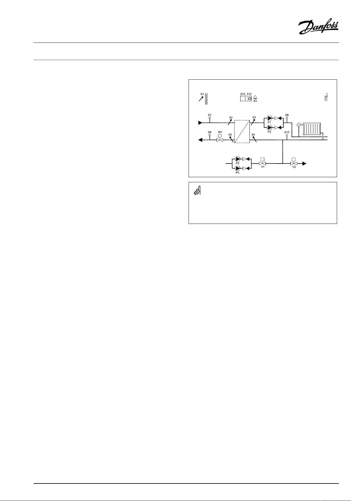
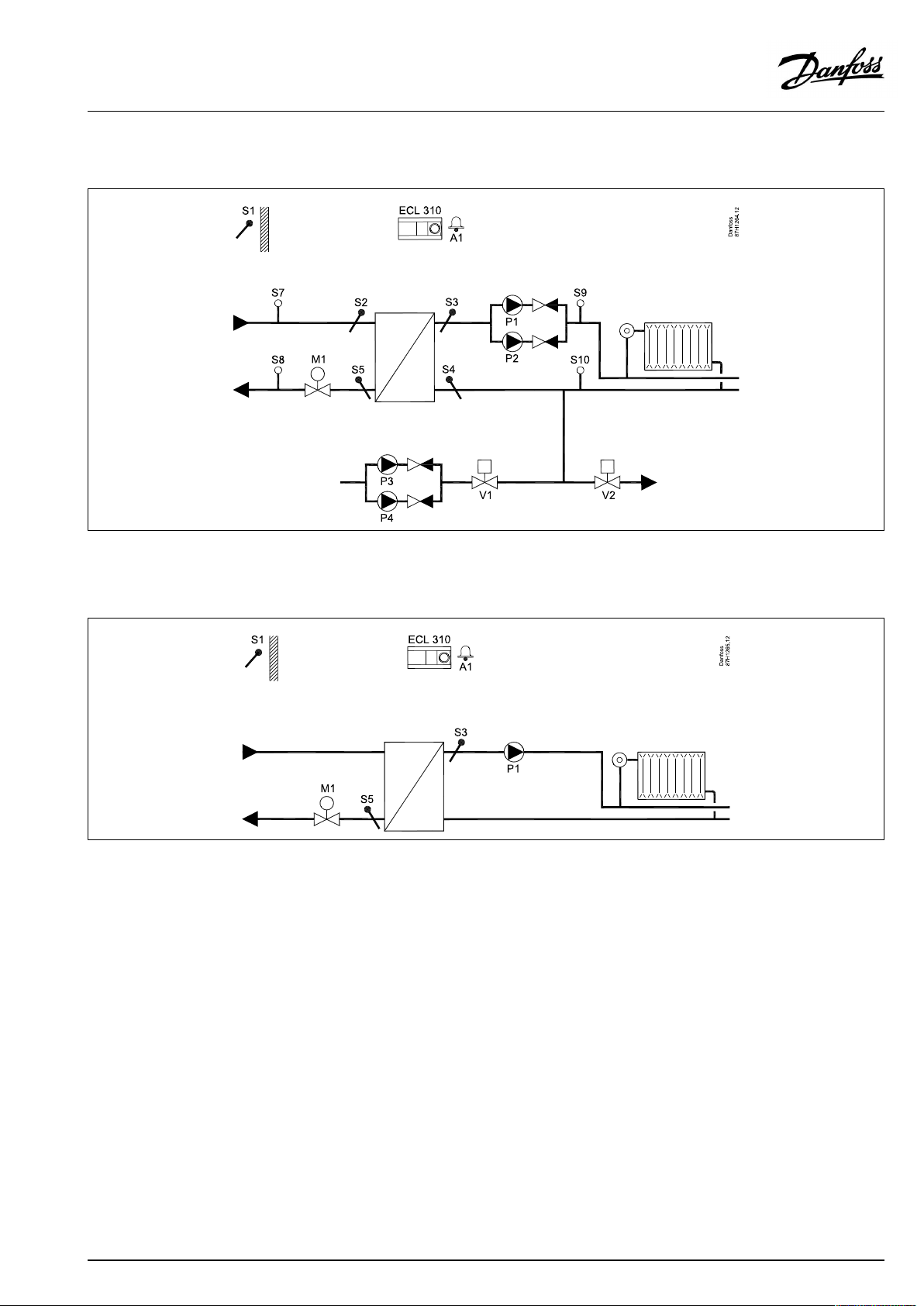
ApplicationA333.1:
Theshowndiagramisafundamentalandsimplifiedexampleanddoes
notcontainallcomponentsthatarenecessaryinasystem.
AllnamedcomponentsareconnectedtotheECLComfortcontroller.
Listofcomponents:
ECL310
ElectroniccontrollerECLComfort310
S1
Outdoortemperaturesensor
S2
(Optional)Primarysupplytemperaturesensor.For
monitoringpurpose
S3
Secondaryflowtemperaturesensor
S4
(Optional)Secondaryreturntemperaturesensor.For
monitoringpurpose
S5
(Optional)Primaryreturntemperaturesensor
S7
(Optional)Primarysupplypressuresensor.Formonitoring
purpose
S8
(Optional)Primaryreturnpressuresensor.Formonitoring
purpose
S9
Secondaryflowpressuresensor
S10
Secondaryreturnpressuresensor
M1
Motorizedcontrolvalve(3-pointcontrolled)
P1/P2
Circulationpumps
P3/P4
Refillwaterpumps
V1
Refillwatervalve
V2
Pressurereleasevalve
A1
Alarm
Thepressuredifferenceonthesecondarysideisbasedonthestatic
pressuresatS9andS10.Thepressuresaremeasuredas0-10volt
signals(frompressuretransmitters)andconverted(scaled)inthe
ECLcontrollertoappropriatepressurevalues.
AQ076586461441en-010401
©Danfoss|2021.04|5
Page 6

OperatingGuideECLComfort310,applicationA333
Ifanacceptablepressuredifferenceisnotdetected,theECL
controlleractivatesthealarmandshiftstheoperatingcommandto
theoppositecirculationpump.
TheheatingcanbeswitchedOFFautomaticallywhentheoutdoor
temperatureishigherthanaselectablevalue.
TheFrostprotectionmodemaintainsaselectableflowtemperature,
forexample10°C.
Incaseofatoolowpressure,measuredbyS10,therefillwater
functionwillsupplementwithwaterfromawatersource.
ArefillpumpisswitchedONandtheON/OFFvalveV1opens.
TherefillpumpsP3andP4areoperatedalternately.Onepumpis
usedasworkingpumpandtheotherpumpisusedassparepump.
Thealternationtimecanbesetasanumberofdays.
Asolutionwithasinglerefillpumpcanalsobeselected.
Incaseofatoohighpressure,measuredbyS10,thereleasevalve
V2(ON/OFF)willopeninordertoreducethepressure.
6|©Danfoss|2021.04
AQ076586461441en-010401
Page 7
OperatingGuideECLComfort310,applicationA333
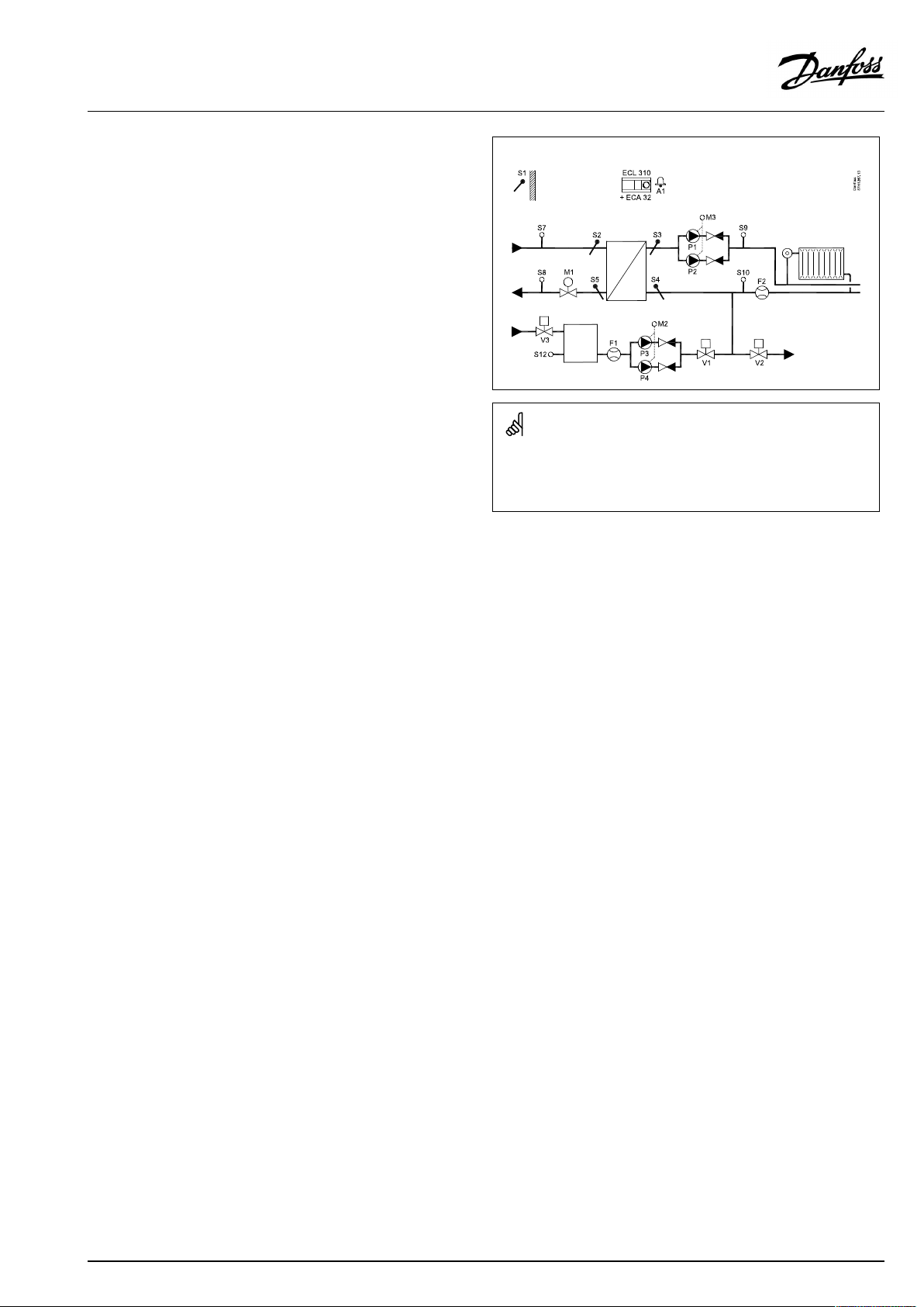
TheapplicationA333.2isveryflexibleandworkslikeA333.1,
andwiththeseadditionalfeatures:
*
ThecirculationpumpsP1/P2can,asanalternativetoON-OFF
control,bespeedcontrolledbymeansofa0-10voltsignal.
ThedesiredpressuredifferencebetweenS9andS10issetfor
thespeedcontrolprocedure.
Aflow-meterF2(pulsesignal,analoguesignalS13orM-Bus)
measuresthecirculationofwaterintheheatingcircuit.
*
Thelevelintherefillwaterstoragetankismeasuredby
meansofthepressuresensorS12.Whenatoolowpressure
ismeasured,theON/OFFvalveV3opens.Anacceptable
pressurewillclosetheV3valve.
*
TherefillwaterpumpsP3/P4can,asanalternativetoON-OFF
control,bespeedcontrolledbymeansofa0-10voltsignal.
ThedesiredpressureatS10issetforthespeedcontrol
procedure.
Aflow-meterF1(pulsesignalorM-Bus)measurestheinjected
refillwater.
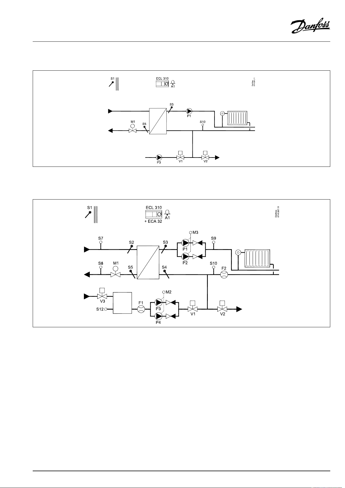
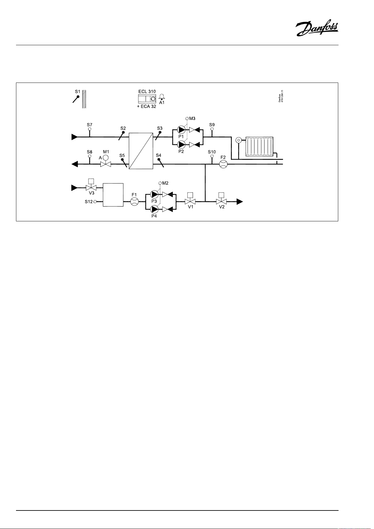
ApplicationA333.2:
Theshowndiagramisafundamentalandsimplifiedexampleanddoes
notcontainallcomponentsthatarenecessaryinasystem.
AllnamedcomponentsareconnectedtotheECLComfortcontroller.
Listofcomponents:
ECL310
ECA32
ElectroniccontrollerECLComfort310
Built-inextensionmodule
S1
Outdoortemperaturesensor
S2
(Optional)Primarysupplytemperaturesensor.For
monitoringpurpose
S3
Secondaryflowtemperaturesensor
S4
(Optional)Secondaryreturntemperaturesensor.For
monitoringpurpose
S5
(Optional)Primaryreturntemperaturesensor
S7
(Optional)Primarysupplypressuresensor.Formonitoring
purpose
S8
(Optional)Primaryreturnpressuresensor.Formonitoring
purpose
S9
Secondaryflowpressuresensor
S10
Secondaryreturnpressuresensor
F1
(Optional)Flowmeter(pulseorM-bussignal)
F2
(Optional)Flowmeter(pulse,0-10voltorM-bussignal)
M1
Motorizedcontrolvalve(3-pointcontrolled)
M2
Speedcontrol(0-10volt)ofP3/P4
M3
Speedcontrol(0-10volt)ofP1/P2
P1/P2
Circulationpumps
P3/P4
Refillwaterpumps
V1
Refillwatervalve
V2
Pressurereleasevalve
V3
Refillwatertankvalve
A1
Alarm
AQ076586461441en-010401
©Danfoss|2021.04|7
Page 8
OperatingGuideECLComfort310,applicationA333
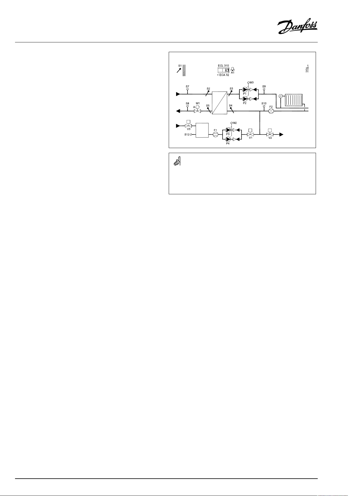
TheapplicationA333.3isveryflexibleandworkslikeA333.2,
butwiththisfeature:
*
ThemotorizedcontrolvalveM1iscontrolledbymeansofa
0-10voltsignal.
ApplicationA333.2:
Theshowndiagramisafundamentalandsimplifiedexampleanddoes
notcontainallcomponentsthatarenecessaryinasystem.
AllnamedcomponentsareconnectedtotheECLComfortcontroller.
Listofcomponents:
ECL310
ECA32
ElectroniccontrollerECLComfort310
Built-inextensionmodule
S1
Outdoortemperaturesensor
S2
(Optional)Primarysupplytemperaturesensor.For
monitoringpurpose
S3
Secondaryflowtemperaturesensor
S4
(Optional)Secondaryreturntemperaturesensor.For
monitoringpurpose
S5
(Optional)Primaryreturntemperaturesensor
S7
(Optional)Primarysupplypressuresensor.Formonitoring
purpose
S8
(Optional)Primaryreturnpressuresensor.Formonitoring
purpose
S9
Secondaryflowpressuresensor
S10
Secondaryreturnpressuresensor
F1
(Optional)Flowmeter(pulseorM-bussignal)
F2
(Optional)Flowmeter(pulse,0-10voltorM-bussignal)
M1
Motorizedcontrolvalve(0-10voltcontrolled)
M2
Speedcontrol(0-10volt)ofP3/P4
M3
Speedcontrol(0-10volt)ofP1/P2
P1/P2
Circulationpumps
P3/P4
Refillwaterpumps
V1
Refillwatervalve
V2
Pressurereleasevalve
V3
Refillwatertankvalve
A1
Alarm
8|©Danfoss|2021.04
AQ076586461441en-010401
Page 9
OperatingGuideECLComfort310,applicationA333
ApplicationA333ingeneral:
UptotwoRemoteControlUnits,theECA30canbeconnectedto
oneECLcontrollerinordertocontroltheECLcontrollerremotely.
Exerciseofcirculationpumpsandcontrolvalveinperiodswithout
heatingdemandcanbearranged.
AdditionalECLComfortcontrollerscanbeconnectedviatheECL
485businordertoutilizecommonoutdoortemperaturesignal,
timeanddatesignals.TheECLControllersintheECL485system
canworkinmaster-slavesystem.
Aconnectedfloworenergymeter(basedonM-bussignal)can
limitthefloworenergytoasetmaximumandinrelationtothe
outdoortemperature.
Unusedinputcan,bymeansofanoverrideswitch,beusedto
overridethescheduletoafixed'Comfort'or'Saving'mode.
ModbuscommunicationtoaSCADAsystemcanbeestablished.
TheM-busdatacanfurthermorebetransferredtotheModbus
communication.
AlarmA1(=relay6)canbeactivated:
•iftheactualflowtemperaturediffersfromthedesiredflow
temperature.
•ifatemperaturesensororitsconnectiondisconnects/short
circuits.(See:Commoncontrollersettings>System>Raw
inputoverview).
•ifthecirculationpump(s)do(es)notgenerateacceptable
pressure.
•iftherefillwaterpump(s)do(es)notgenerateacceptable
pressure.
•ifmeasuredpressuresarenotinsideanacceptablepressure
range.
Thecontrollerispre-programmedwithfactorysettingsthatareshown
inthe‘ParameterIDoverview’appendix.
AQ076586461441en-010401
©Danfoss|2021.04|9
Page 10
OperatingGuideECLComfort310,applicationA333
2.2Identifyingthesystemtype
Sketchyourapplication
TheECLComfortcontrollerseriesisdesignedforawiderange
ofheating,domestichot-water(DHW)andcoolingsystemswith
differentconfigurationsandcapacities.Ifyoursystemdiffers
fromthediagramsshownhere,youmaywanttomakeasketch
ofthesystemabouttobeinstalled.Thismakesiteasiertouse
theOperatingGuide,whichwillguideyoustep-by-stepfrom
installationtofinaladjustmentsbeforetheend-usertakesover.
TheECLComfortcontrollerisauniversalcontrollerthatcanbe
usedforvarioussystems.Basedontheshownstandardsystems,
itispossibletoconfigureadditionalsystems.Inthischapteryou
findthemostfrequentlyusedsystems.Ifyoursystemisnotquite
asshownbelow,findthediagramwhichhasthebestresemblance
withyoursystemandmakeyourowncombinations.
SeetheInstallationGuide(deliveredwiththeapplicationkey)for
applicationtypes/sub-types.
Thecirculationpump(s)inheatingcircuit(s)canbeplacedintheflow
aswellasthereturn.Placethepumpaccordingtothemanufacturer’s
specification.
10|©Danfoss|2021.04
AQ076586461441en-010401
Page 11
OperatingGuideECLComfort310,applicationA333
A333.1,ex.a
Heatingsystemwithcontrolofupto2circulationpumpsandupto2refillwaterpumps
A333.1,ex.b
Basicheatingsystem
AQ076586461441en-010401
©Danfoss|2021.04|11
Page 12
OperatingGuideECLComfort310,applicationA333
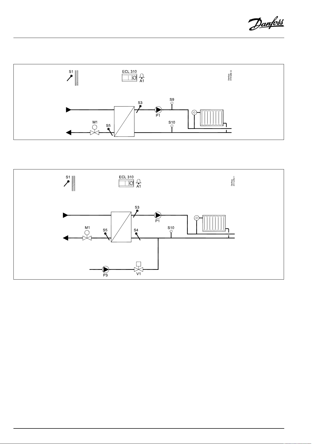
A333.1,ex.c
Heatingsystemwithcirculationpumpfeedback
A333.1,ex.d
Heatingsystemwithrefillwatersystem
12|©Danfoss|2021.04
AQ076586461441en-010401
Page 13
OperatingGuideECLComfort310,applicationA333
A333.1,ex.e
Heatingsystemwithrefillwaterandexcesspressuresystem
A333.2,ex.a
HeatingsystemwithON/OFFandspeedcontrolofupto2circulationpumpsandupto2refillwaterpumps.Refillwaterstoragecontrol.
AQ076586461441en-010401
©Danfoss|2021.04|13
Page 14
OperatingGuideECLComfort310,applicationA333
A333.3,ex.a
HeatingsystemwithON/OFFandspeedcontrolofupto2circulationpumpsandupto2refillwaterpumps.Refillwaterstoragecontrol.
ControlvalveM1iscontrolledby0-10voltsignal.
14|©Danfoss|2021.04
AQ076586461441en-010401
Page 15
OperatingGuideECLComfort310,applicationA333
2.3Mounting
2.3.1MountingtheECLComfortcontroller
SeetheInstallationGuidewhichisdeliveredtogetherwiththe
ECLComfortcontroller.
Foreasyaccess,youshouldmounttheECLComfortcontrollernear
thesystem.
ECLComfort210/296/310canbemounted
•onawall
•onaDINrail(35mm)
ECLComfort296canbemounted
•inapanelcut-out
ECLComfort210canbemountedinanECLComfort310basepart
(forfutureupgrade).
Screws,PGcableglandsandrawlplugsarenotsupplied.
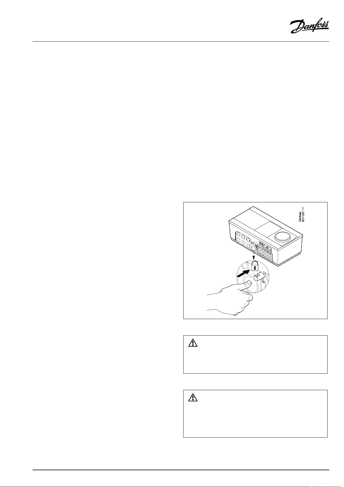
LockingtheECLComfort210/310controller
InordertofastentheECLComfortcontrollertoitsbasepart,secure
thecontrollerwiththelockingpin.
Topreventinjuriestopersonsorthecontroller,thecontrollerhasto
besecurelylockedintothebase.Forthispurpose,pressthelocking
pinintothebaseuntilaclickisheardandthecontrollernolonger
canberemovedfromthebase.
Ifthecontrollerisnotsecurelylockedintothebasepart,thereisarisk
thatthecontrollerduringoperationcanunlockfromthebaseandthe
basewithterminals(andalsothe230Va.c.connections)areexposed.
Topreventinjuriestopersons,alwaysmakesurethatthecontroller
issecurelylockedintoitsbase.Ifthisisnotthecase,thecontroller
shouldnotbeoperated!
AQ076586461441en-010401
©Danfoss|2021.04|15
Page 16
OperatingGuideECLComfort310,applicationA333
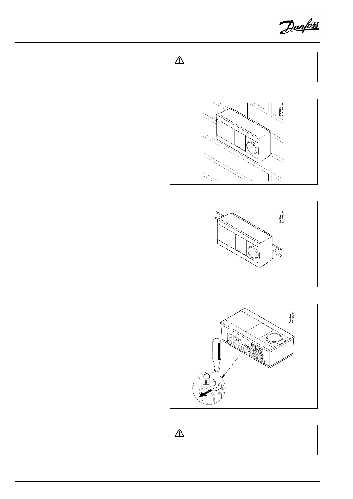
Mountingonawall
Mountthebasepartonawallwithasmoothsurface.Establishthe
electricalconnectionsandpositionthecontrollerinthebasepart.
Securethecontrollerwiththelockingpin.
MountingonaDINrail(35mm)
MountthebasepartonaDINrail.Establishtheelectrical
connectionsandpositionthecontrollerinthebasepart.Secure
thecontrollerwiththelockingpin.
Theeasywaytolockthecontrollertoitsbaseorunlockitistousea
screwdriveraslever.
DismountingtheECLComfortcontroller
Inordertoremovethecontrollerfromthebasepart,pulloutthe
lockingpinbymeansofascrewdriver.Thecontrollercannowbe
removedfromthebasepart.
Theeasywaytolockthecontrollertoitsbaseorunlockitistousea
screwdriveraslever.
16|©Danfoss|2021.04
AQ076586461441en-010401
Page 17
OperatingGuideECLComfort310,applicationA333
2.3.2MountingtheRemoteControlUnitsECA30/31
Selectoneofthefollowingmethods:
•Mountingonawall,ECA30/31
•Mountinginapanel,ECA30
Screwsandrawlplugsarenotsupplied.
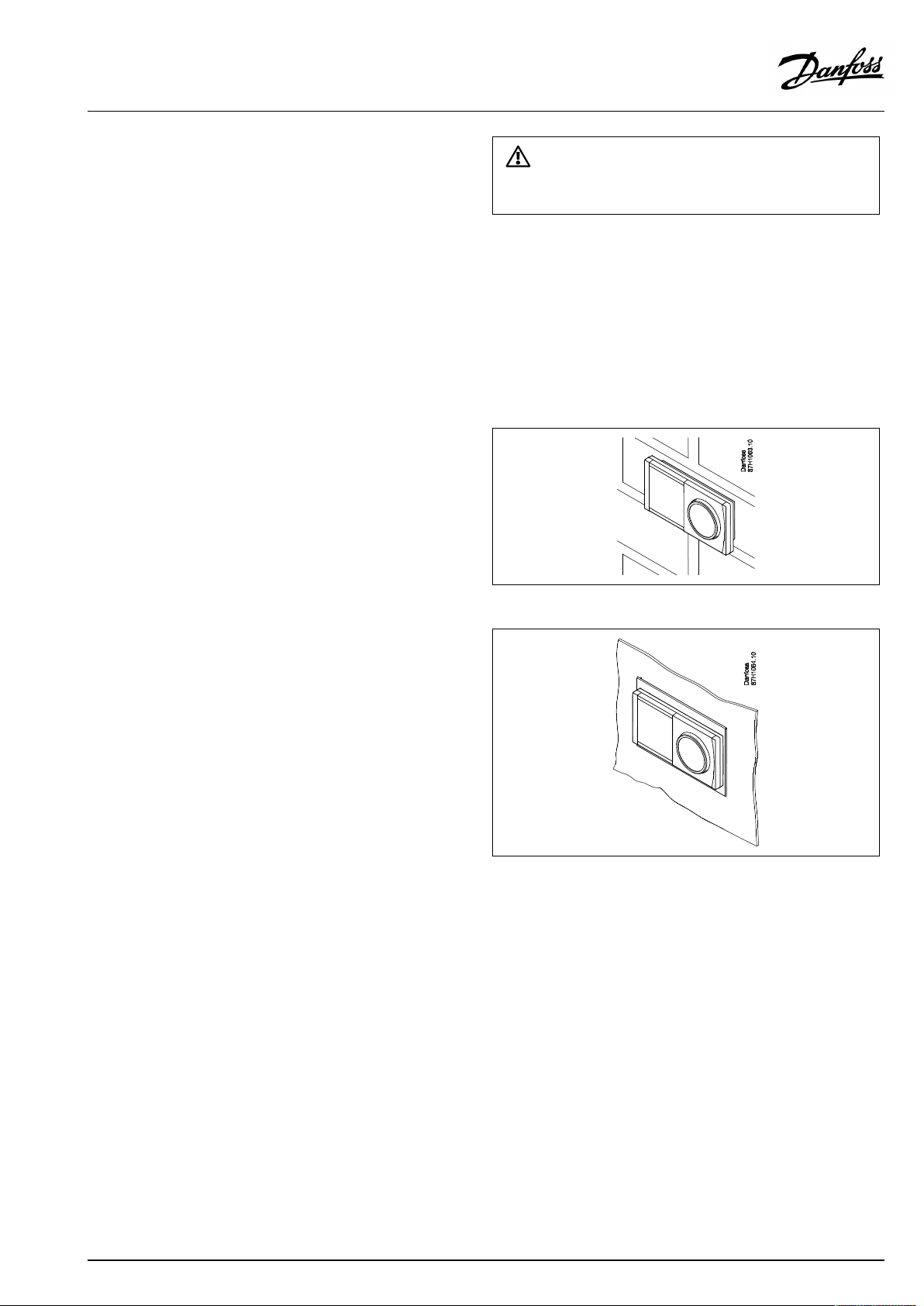
Mountingonawall
MountthebasepartoftheECA30/31onawallwithasmooth
surface.Establishtheelectricalconnections.PlacetheECA30/
31inthebasepart.
BeforeremovingtheECLComfortcontrollerfromthebasepart,ensure
thatthesupplyvoltageisdisconnected.
Mountinginapanel
MounttheECA30inapanelusingtheECA30framekit(ordercode
no.087H3236).Establishtheelectricalconnections.Securethe
framewiththeclamp.PlacetheECA30inthebasepart.TheECA
30canbeconnectedtoanexternalroomtemperaturesensor.
TheECA31mustnotbemountedinapanelifthehumidity
functionistobeused.
AQ076586461441en-010401
©Danfoss|2021.04|17
Page 18
OperatingGuideECLComfort310,applicationA333
2.4Placingthetemperaturesensors
2.4.1Placingthetemperaturesensors
Itisimportantthatthesensorsaremountedinthecorrectposition
inyoursystem.
Thetemperaturesensormentionedbelowaresensorsusedforthe
ECLComfort210/296/310serieswhichnotallwillbeneeded
foryourapplication!
Outdoortemperaturesensor(ESMT)
Theoutdoorsensorshouldbemountedonthatsideofthebuilding
whereitislesslikelytobeexposedtodirectsunshine.Itshouldnot
beplacedclosetodoors,windowsorairoutlets.
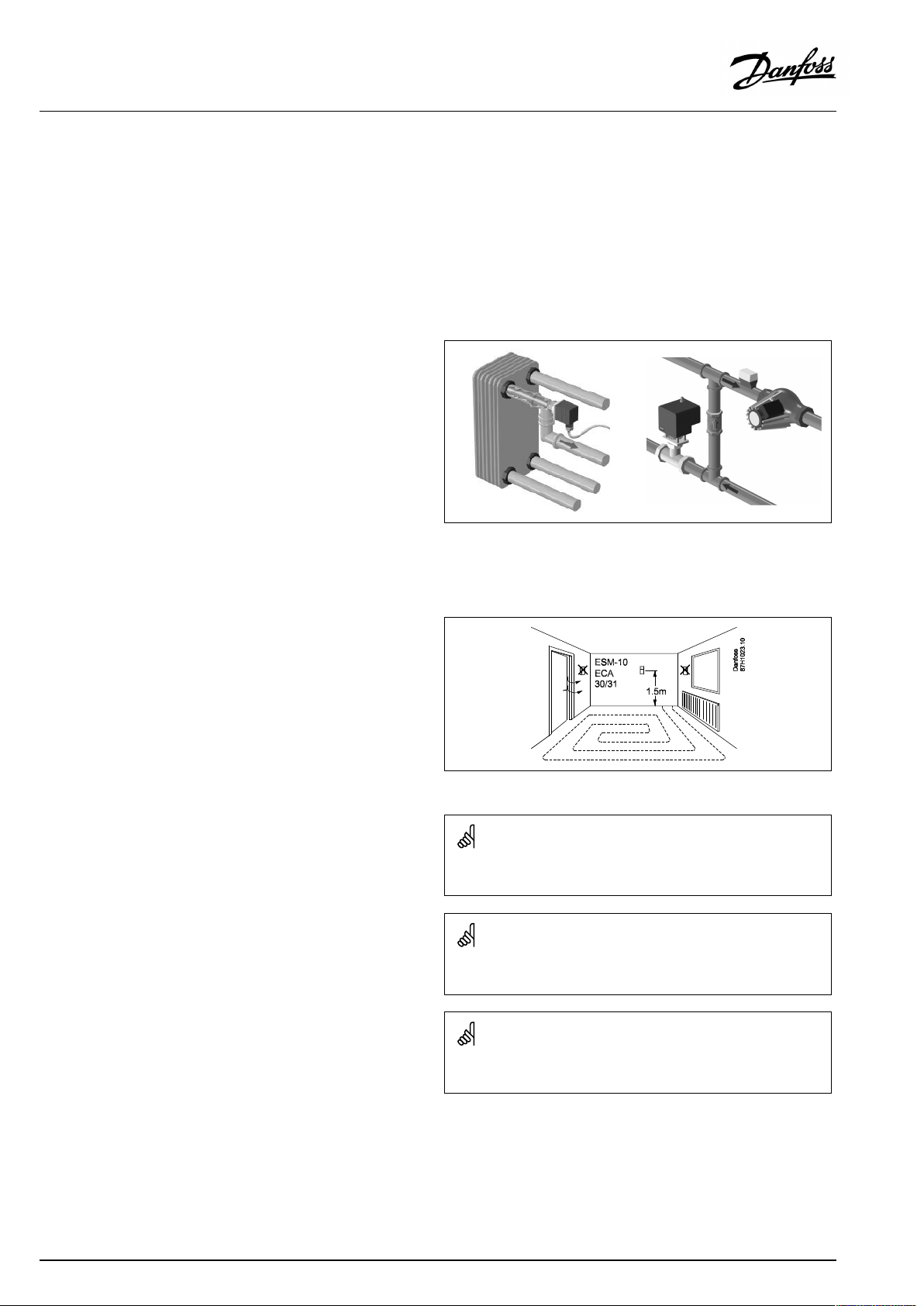
Flowtemperaturesensor(ESMU,ESM-11orESMC)
Placethesensormax.15cmfromthemixingpoint.Insystems
withheatexchanger,DanfossrecommendsthattheESMU-typeto
beinsertedintotheexchangerflowoutlet.
Makesurethatthesurfaceofthepipeiscleanandevenwhere
thesensorismounted.
Returntemperaturesensor(ESMU,ESM-11orESMC)
Thereturntemperaturesensorshouldalwaysbeplacedsothatit
measuresarepresentativereturntemperature.
Roomtemperaturesensor
(ESM-10,ECA30/31RemoteControlUnit)
Placetheroomsensorintheroomwherethetemperatureistobe
controlled.Donotplaceitonoutsidewallsorclosetoradiators,
windowsordoors.
Boilertemperaturesensor(ESMU,ESM-11orESMC)
Placethesensoraccordingtotheboilermanufacturer’s
specification.
Airducttemperaturesensor(ESMB-12orESMUtypes)
Placethesensorsothatitmeasuresarepresentativetemperature.
DHWtemperaturesensor(ESMUorESMB-12)
PlacetheDHWtemperaturesensoraccordingtothemanufacturer’s
specification.
Slabtemperaturesensor(ESMB-12)
Placethesensorinaprotectiontubeintheslab.
ESM-11:Donotmovethesensorafterithasbeenfastenedinorderto
avoiddamagetothesensorelement.
ESM-11,ESMCandESMB-12:Useheatconductingpasteforquick
measurementofthetemperature.
ESMUandESMB-12:Usingasensorpockettoprotectthesensorwill,
however,resultinaslowertemperaturemeasurement.
18|©Danfoss|2021.04
AQ076586461441en-010401
Page 19
OperatingGuideECLComfort310,applicationA333
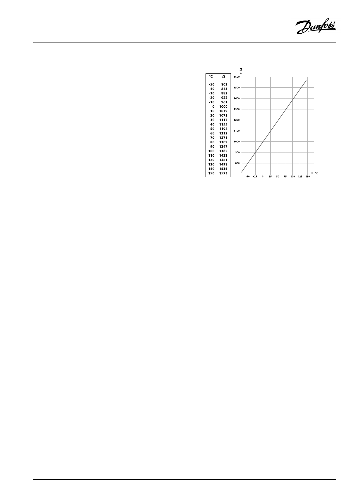
Pt1000temperaturesensor(IEC751B,1000Ω/0°C)
Relationshipbetweentemperatureandohmicvalue:
AQ076586461441en-010401
©Danfoss|2021.04|19
Page 20
OperatingGuideECLComfort310,applicationA333
2.5Electricalconnections
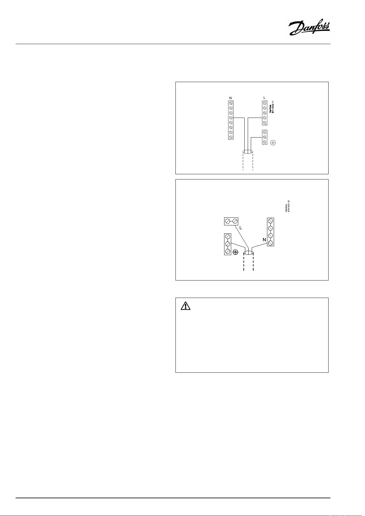
2.5.1Electricalconnections230Va.c.
Thecommongroundterminalisusedforconnectionofrelevant
components(pumps,motorizedcontrolvalves).
ECL210/310
ECL296
Warning
ElectricconductorsonPCB(PrintedCircuitBoard)forsupplyvoltage,
relaycontactsandtriacoutputsdonothavemutualsafetydistanceof
minimum6mm.Theoutputsarenotallowedtobeusedasgalvanic
separated(voltfree)outputs.
Ifagalvanicseparatedoutputisneeded,anauxiliaryrelayis
recommended.
24Voltcontrolledunits,forexampleactuators,aretobecontrolledby
meansofECLComfort310,24Voltversion.
20|©Danfoss|2021.04
AQ076586461441en-010401
Page 21

OperatingGuideECLComfort310,applicationA333
SafetyNote
Necessaryassembly,start-up,andmaintenanceworkmustbe
performedbyqualifiedandauthorizedpersonnelonly.
Locallegislationsmustberespected.Thiscomprisesalsocablesize
andisolation(reinforcedtype).
AfusefortheECLComfortinstallationismax.10Atypically.
TheambienttemperaturerangefortheECLComfortinoperationis
0-55°C.Exceedingthistemperaturerangecanresultinmalfunctions.
Installationmustbeavoidedifthereisariskforcondensation(dew).
AQ076586461441en-010401
©Danfoss|2021.04|21
Page 22
OperatingGuideECLComfort310,applicationA333
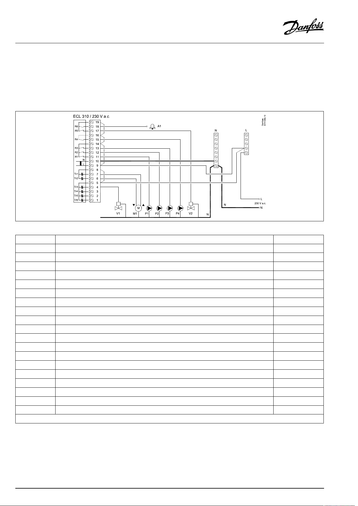
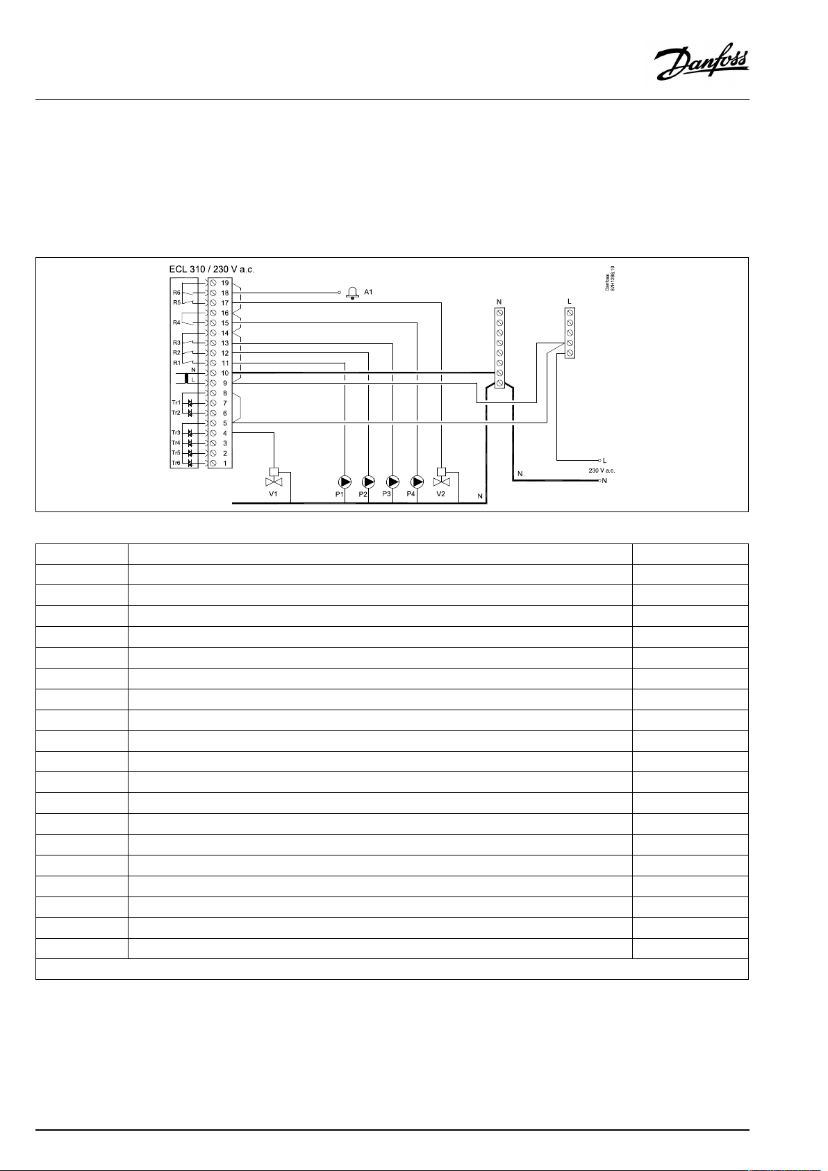
2.5.2Electricalconnections,230Va.c.,powersupply,pumps,dampers,motorizedcontrolvalvesetc.
ConnectionsforA333.1andA333.2,ingeneral:
SeealsotheMountingGuide(deliveredwiththeapplicationkey)forapplicationspecificconnections.
ApplicationA333.1/A333.2
Terminal
19
18
A1
17
V2
16
15
P4
14
13
P3
12
P2
11
P1
10
9
8
7
M1
6
M1
5
4
V1
3
2
1
*Relaycontacts:4Aforohmicload,2Aforinductiveload
Description
PhaseforON/OFFvalve/Alarm
Alarm
ON/OFFvalveforpressurerelease
Phaseforrefillwaterpump
Refillwaterpump
Phaseforcirculationpumps/refillwaterpump
Refillwaterpump
Circulationpump
Circulationpump
Supplyvoltage230Va.c.-neutral(N)
Supplyvoltage230Va.c.-live(L)
PhaseformotorizedcontrolvalveM1
Motorizedcontrolvalve-opening
Motorizedcontrolvalve-closing
PhaseforON/OFFvalveV1
ON/OFFvalveforrefillwater
Nottobeused
Nottobeused
Nottobeused
Max.load
4(2)A/230Va.c.*
4(2)A/230Va.c.*
4(2)A/230Va.c.*
4(2)A/230Va.c.*
4(2)A/230Va.c.*
4(2)A/230Va.c.*
0.2A/230Va.c.
0.2A/230Va.c.
0.2A/230Va.c.
Factoryestablishedjumpers:
5to8,9to14,Lto5andLto9,Nto10
22|©Danfoss|2021.04
AQ076586461441en-010401
Page 23

OperatingGuideECLComfort310,applicationA333
Wirecrosssection:0.5-1.5mm²
Incorrectconnectioncandamagetheelectronicoutputs.
Max.2x1.5mm²wirescanbeinsertedintoeachscrewterminal.
AQ076586461441en-010401
©Danfoss|2021.04|23
Page 24
OperatingGuideECLComfort310,applicationA333
2.5.3Electricalconnections,230Va.c.,powersupply,pumps,dampers,motorizedcontrolvalvesetc.
ConnectionsforA333.3,ingeneral:
SeealsotheMountingGuide(deliveredwiththeapplicationkey)forapplicationspecificconnections.
ApplicationA333.3
Terminal
19
18
A1
17
V2
16
15
P4
14
13
P3
12
P2
11
P1
10
9
8
7
6
5
4
V1
3
2
1
*Relaycontacts:4Aforohmicload,2Aforinductiveload
Description
PhaseforON/OFFvalve/Alarm
Alarm
ON/OFFvalveforpressurerelease
Phaseforrefillwaterpump
Refillwaterpump
Phaseforcirculationpumps/refillwaterpump
Refillwaterpump
Circulationpump
Circulationpump
Supplyvoltage230Va.c.-neutral(N)
Supplyvoltage230Va.c.-live(L)
Nottobeused
Nottobeused
Nottobeused
PhaseforON/OFFvalveV1
ON/OFFvalveforrefillwater
Nottobeused
Nottobeused
Nottobeused
Max.load
4(2)A/230Va.c.*
4(2)A/230Va.c.*
4(2)A/230Va.c.*
4(2)A/230Va.c.*
4(2)A/230Va.c.*
4(2)A/230Va.c.*
0.2A/230Va.c.
0.2A/230Va.c.
0.2A/230Va.c.
0.2A/230Va.c.
Factoryestablishedjumpers:
5to8,9to14,Lto5andLto9,Nto10
24|©Danfoss|2021.04
AQ076586461441en-010401
Page 25

OperatingGuideECLComfort310,applicationA333
Wirecrosssection:0.5-1.5mm²
Incorrectconnectioncandamagetheelectronicoutputs.
Max.2x1.5mm²wirescanbeinsertedintoeachscrewterminal.
AQ076586461441en-010401
©Danfoss|2021.04|25
Page 26

OperatingGuideECLComfort310,applicationA333
2.5.4Electricalconnections,ECA32
ConnectionsforA333.2andA333.3,ingeneral:
SeealsotheMountingGuide(deliveredwiththeapplicationkey)forapplicationspecificconnections.
Terminal
39
R10
40
R10
41
R9
42
R9
43
R8
44
R8
45
R8
46
R7
47
R7
48
R7
49
50
S11
51
S12
52
S13
53
54
55
Description
Relay10,notused
Relay9,notused
Relay8,notused
Relay7
V3,ON/OFFvalveforpressurerelease
PhaseforON/OFFvalveV3
Commonterminalforinputsignals
Input:PositionsignalfromM1,0-10volt
Input:Refillwaterlevelinstoragetank,0-10volt
Input:F2flowsignal,0-10volt
Nottobeused
Nottobeused
Nottobeused
Max.load
4(2)A/230Va.c.*
4(2)A/230Va.c.*
4(2)A/230Va.c.*
4(2)A/230Va.c.*
56
57
F1
58
F2
59
M1
60
M2
61
M3
62
*Relaycontacts:4Aforohmicload,2Aforinductiveload
**Min.resistance:5KΩ
ReferenceterminalforAnalogueout2(M2)and3(M3)
Input:Flow-meter,pulsetype
Input:Flow-meter,pulsetype
Analogueout1:0-10voltforcontrolofmotorizedcontrolvalveM1(A333.3)
Analogueout2:0-10voltforspeedcontrolofrefillwaterpumpsP3andP4(A333.2,A333.3)
Analogueout3:0-10voltforspeedcontrolofcirculationpumpsP1andP2(A333.2,A333.3)
ReferenceterminalforAnalogueout1(M1)
2mA**
2mA**
2mA**
26|©Danfoss|2021.04
AQ076586461441en-010401
Page 27
OperatingGuideECLComfort310,applicationA333
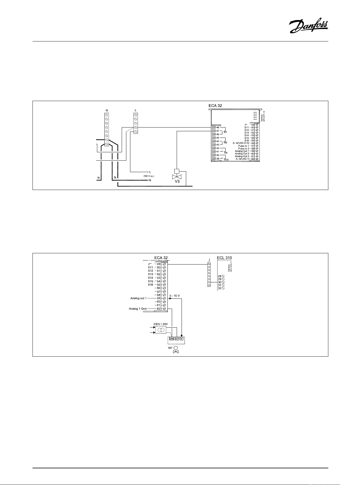
2.5.5Electricalconnections,ON/OFFvalveV3controlledfromrelayoutputinECA32
ConnectionsforA333.2andA333.3,ingeneral:
SeealsotheMountingGuide(deliveredwiththeapplicationkey)forapplicationspecificconnections.
ApplicationA333.2/A333.3
2.5.6Electricalconnections,230Va.c.,powersupply,motorizedcontrolvalveM1controlledby0-10voltfromECA32
ConnectionsforA333.3,ingeneral:
SeealsotheMountingGuide(deliveredwiththeapplicationkey)forapplicationspecificconnections.
ApplicationA333.3
Thetransformerforsupplyingtheactuatormustbeadouble-isolatedversion.
AQ076586461441en-010401
©Danfoss|2021.04|27
Page 28
OperatingGuideECLComfort310,applicationA333
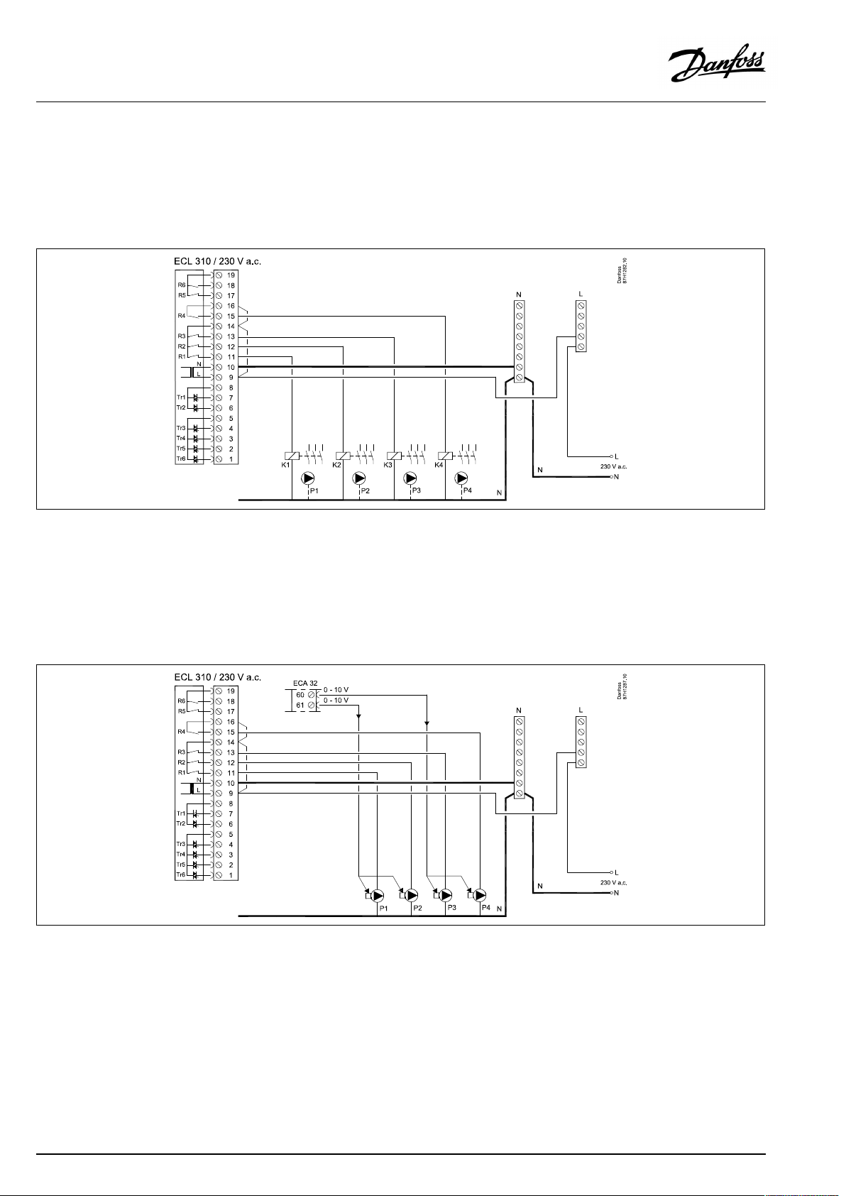
2.5.7Electricalconnections,230Va.c.,powersupply,controlof2or3phasepoweredpumps
ConnectionsforA333.1,ingeneral:
SeealsotheMountingGuide(deliveredwiththeapplicationkey)forapplicationspecificconnections.
ApplicationA333.1
2.5.8Electricalconnections,230Va.c.,powersupply,ON/OFFcontrolandspeedcontrolof1phasepoweredpumps
ConnectionsforA333.2andA333.3,ingeneral:
SeealsotheMountingGuide(deliveredwiththeapplicationkey)forapplicationspecificconnections.
ApplicationA333.2/A333.3
28|©Danfoss|2021.04
AQ076586461441en-010401
Page 29
OperatingGuideECLComfort310,applicationA333
2.5.9Electricalconnections,230Va.c.,powersupply,0-10voltforspeedcontrolof1phasepoweredpumps
ConnectionsforA333.2andA333.3,ingeneral:
SeealsotheMountingGuide(deliveredwiththeapplicationkey)forapplicationspecificconnections.
ApplicationA333.2/A333.3
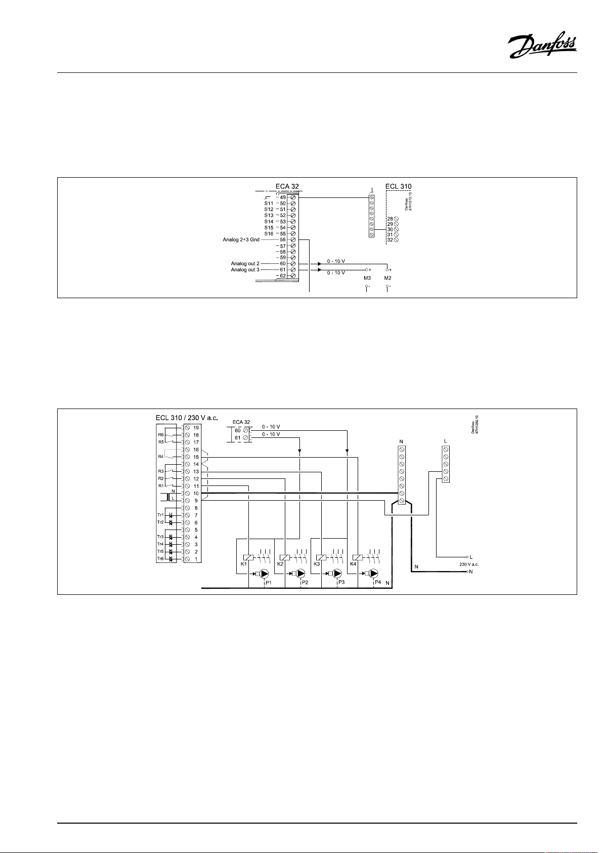
2.5.10Electricalconnections,230Va.c.,powersupply ,ON/OFFcontrolandspeedcontrolof2or3phasepoweredpumps
ConnectionsforA333.2andA333.3,ingeneral:
SeealsotheMountingGuide(deliveredwiththeapplicationkey)forapplicationspecificconnections.
ApplicationA333.2/A333.3
AQ076586461441en-010401
©Danfoss|2021.04|29
Page 30
OperatingGuideECLComfort310,applicationA333
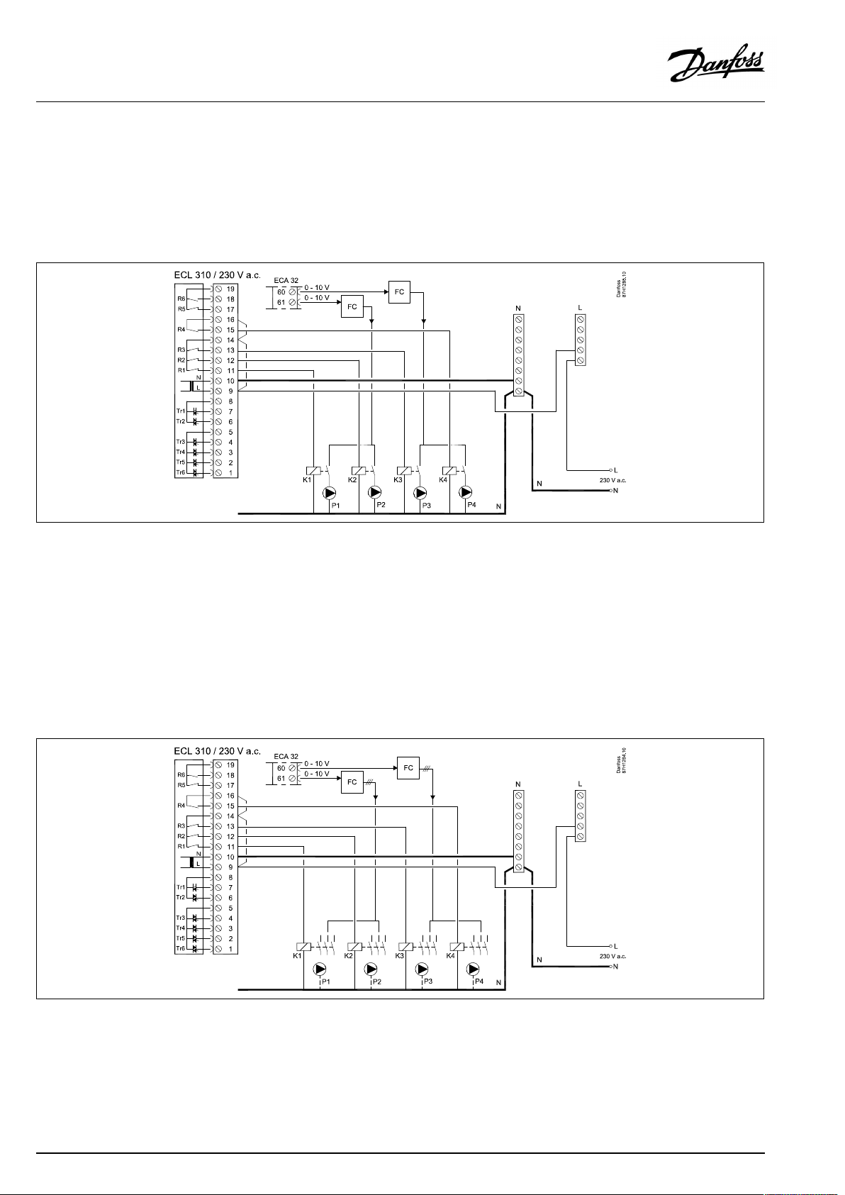
2.5.11Electricalconnections,230Va.c.,powersupply,ON/OFFcontrolandspeedcontrol(viaFrequencyConverter)of1
phasepoweredpumps
ConnectionsforA333.2andA333.3,ingeneral:
SeealsotheMountingGuide(deliveredwiththeapplicationkey)forapplicationspecificconnections.
ApplicationA333.2/A333.3
FC=FrequencyConverter
2.5.12Electricalconnections,230Va.c.,powersupply,ON/OFFcontrolandspeedcontrol(viaFrequencyConverter)of2
or3phasepoweredpumps
ConnectionsforA333.2andA333.3,ingeneral:
SeealsotheMountingGuide(deliveredwiththeapplicationkey)forapplicationspecificconnections.
ApplicationA333.2/A333.3
FC=FrequencyConverter
30|©Danfoss|2021.04
AQ076586461441en-010401
Page 31

OperatingGuideECLComfort310,applicationA333
2.5.13Electricalconnections,examplewithexternalStart/StopcontrolofaFrequencyConverterforcirculationpumpsP1/P2
ApplicationA333.2/A333.3
FC=FrequencyConverter
2.5.14Electricalconnections,examplewithexternalStart/StopcontrolofaFrequencyConverterforrefillwaterpumpsP3/P4
ApplicationA333.2/A333.3
FC=FrequencyConverter
AQ076586461441en-010401
©Danfoss|2021.04|31
Page 32

OperatingGuideECLComfort310,applicationA333
2.5.15Electricalconnections,safetythermostats,230Va.c.or24Va.c.
Withsafetythermostat,1–stepclosing:
Motorizedcontrolvalvewithoutsafetyfunction
Withsafetythermostat,1–stepclosing:
Motorizedcontrolvalvewithsafetyfunction
Withsafetythermostat,2–stepclosing:
Motorizedcontrolvalvewithsafetyfunction
32|©Danfoss|2021.04
AQ076586461441en-010401
Page 33

OperatingGuideECLComfort310,applicationA333
WhenSTisactivatedbyahightemperature,thesafetycircuitinthe
motorizedcontrolvalveclosesthevalveimmediately.
WhenST1isactivatedbyahightemperature(theTRtemperature),the
motorizedcontrolvalveisclosedgradually.Atahighertemperature
(theSTtemperature),thesafetycircuitinthemotorizedcontrolvalve
closesthevalveimmediately.
Wirecrosssection:0.5-1.5mm²
Incorrectconnectioncandamagetheelectronicoutputs.
Max.2x1.5mm²wirescanbeinsertedintoeachscrewterminal.
AQ076586461441en-010401
©Danfoss|2021.04|33
Page 34

OperatingGuideECLComfort310,applicationA333
2.5.16Electricalconnections,24Va.c.(ECL310only),powersupply,pumps,motorizedvalvesetc.
ConnectionsforA333.1andA333.2,ingeneral:
SeealsotheMountingGuide(deliveredwiththeapplicationkey)forapplicationspecificconnections.
ApplicationA333.1/A333.2
Terminal
19
18
A1
17
V2
16
15
P4
14
13
P3
12
P2
11
P1
10
9
8
7
M1
6
M1
5
4
V1
3
2
1
*Relaycontacts:4Aforohmicload,2Aforinductiveload
Description
Supplyvoltage(SP)forON/OFFvalve/Alarm
Alarm
ON/OFFvalveforpressurerelease
Supplyvoltage(SP)forrefillwaterpump
Refillwaterpump
Supplyvoltage(SP)forcirculationpumps/refillwaterpump
Refillwaterpump
Circulationpump
Circulationpump
Supplyvoltage24Va.c.-(SN)
Supplyvoltage24Va.c.-(SP)
Supplyvoltage(SP)formotorizedcontrolvalveM1
Motorizedcontrolvalve-opening
Motorizedcontrolvalve-closing
Supplyvoltage(SP)forON/OFFvalveV1
ON/OFFvalveforrefillwater
Nottobeused
Nottobeused
Nottobeused
Max.load
4(2)A/24Va.c.*
4(2)A/24Va.c.*
4(2)A/24Va.c.*
4(2)A/24Va.c.*
4(2)A/24Va.c.*
4(2)A/24Va.c.*
1A/24Va.c.
1A/24Va.c.
1A/24Va.c.
Factoryestablishedjumpers:
5to8,9to14,Lto5andLto9,Nto10
34|©Danfoss|2021.04
AQ076586461441en-010401
Page 35

OperatingGuideECLComfort310,applicationA333
Wirecrosssection:0.5-1.5mm²
Incorrectconnectioncandamagetheelectronicoutputs.
Max.2x1.5mm²wirescanbeinsertedintoeachscrewterminal.
Donotconnect230Va.c.poweredcomponentstoa24Va.c.power
suppliedcontrollerdirectly.Useauxilliaryrelays(K)toseparate230
Va.c.from24Va.c.
AQ076586461441en-010401
©Danfoss|2021.04|35
Page 36

OperatingGuideECLComfort310,applicationA333
2.5.17Electricalconnections,24Va.c.(ECL310only),powersupply,pumps,motorizedvalvesetc.
ConnectionsforA333.3,ingeneral:
SeealsotheMountingGuide(deliveredwiththeapplicationkey)forapplicationspecificconnections.
ApplicationA333.3
Terminal
19
18
A1
17
V2
16
15
P4
14
13
P3
12
P2
11
P1
10
9
8
7
6
5
4
V1
3
2
1
*Relaycontacts:4Aforohmicload,2Aforinductiveload
Description
Supplyvoltage(SP)forON/OFFvalve/Alarm
Alarm
ON/OFFvalveforpressurerelease
Supplyvoltage(SP)forrefillwaterpump
Refillwaterpump
Supplyvoltage(SP)forcirculationpumps/refillwaterpump
Refillwaterpump
Circulationpump
Circulationpump
Supplyvoltage24Va.c.-(SN)
Supplyvoltage24Va.c.-(SP)
Nottobeused
Nottobeused
Nottobeused
Supplyvoltage(SP)forON/OFFvalveV1
ON/OFFvalveforrefillwater
Nottobeused
Nottobeused
Nottobeused
Max.load
4(2)A/24Va.c.*
4(2)A/24Va.c.*
4(2)A/24Va.c.*
4(2)A/24Va.c.*
4(2)A/24Va.c.*
4(2)A/24Va.c.*
1A/24Va.c.
Factoryestablishedjumpers:
5to8,9to14,Lto5andLto9,Nto10
36|©Danfoss|2021.04
AQ076586461441en-010401
Page 37

OperatingGuideECLComfort310,applicationA333
Wirecrosssection:0.5-1.5mm²
Incorrectconnectioncandamagetheelectronicoutputs.
Max.2x1.5mm²wirescanbeinsertedintoeachscrewterminal.
Donotconnect230Va.c.poweredcomponentstoa24Va.c.power
suppliedcontrollerdirectly.Useauxilliaryrelays(K)toseparate230
Va.c.from24Va.c.
AQ076586461441en-010401
©Danfoss|2021.04|37
Page 38

OperatingGuideECLComfort310,applicationA333
2.5.18Electricalconnections,ECA32
ConnectionsforA333.2andA333.3,ingeneral:
SeealsotheMountingGuide(deliveredwiththeapplicationkey)forapplicationspecificconnections.
Terminal
39
R10
40
R10
41
R9
42
R9
43
R8
44
R8
45
R8
46
R7
47
R7
48
R7
49
50
S11
51
S12
52
S13
53
54
55
Description
Relay10,notused
Relay9,notused
Relay8,notused
Relay7
V3,ON/OFFvalveforpressurerelease
PhaseforON/OFFvalveV3
Commonterminalforinputsignals
Input:PositionsignalfromM1,0-10volt
Input:Refillwaterlevelinstoragetank,0-10volt
Input:F2flowsignal,0-10volt
Input:notused
Input:notused
Input:notused
Max.load
4(2)A/24Va.c.*
4(2)A/24Va.c.*
4(2)A/24Va.c.*
4(2)A/24Va.c.*
56
57
F1
58
F2
59
M1
60
M2
61
M3
62
*Relaycontacts:4Aforohmicload,2Aforinductiveload
**Min.resistance:5KΩ
ReferenceterminalforAnalogueout2(M2)and3(M3)
Input:Flow-meter,pulsetype
Input:Flow-meter,pulsetype
Analogueout1:0-10voltforcontrolofmotorizedcontrolvalveM1(A333.3)
Analogueout2:0-10voltforspeedcontrolofrefillwaterpumpsP3andP4(A333.2,A333.3)
Analogueout3:0-10voltforspeedcontrolofcirculationpumpsP1andP2(A333.2,A333.3)
ReferenceterminalforAnalogueout1(M1)
2mA**
2mA**
2mA**
38|©Danfoss|2021.04
AQ076586461441en-010401
Page 39

OperatingGuideECLComfort310,applicationA333
2.5.19Electricalconnections,24Va.c.,powersupply,ON/OFFvalveV3controlledfromrelayoutputinECA32
ConnectionsforA333.2andA333.3,ingeneral:
SeealsotheMountingGuide(deliveredwiththeapplicationkey)forapplicationspecificconnections.
ApplicationA333.2/A333.3
2.5.20Electricalconnections,24Va.c.,powersupply,motorizedcontrolvalveM1controlledby0-10voltfromECA32
ConnectionsforA333.3,ingeneral:
SeealsotheMountingGuide(deliveredwiththeapplicationkey)forapplicationspecificconnections.
ApplicationA333.3
Thetransformerforsupplyingtheactuatormustbeadouble-isolatedversion.
TheECLComfort310andtheactuatorforthecontrolvalveM1musthaveseparatetransformers.
AQ076586461441en-010401
©Danfoss|2021.04|39
Page 40

OperatingGuideECLComfort310,applicationA333
2.5.21Electricalconnections,24Va.c.,powersupply,controlof2or3phasepoweredpumps
ConnectionsforA333.1,ingeneral:
SeealsotheMountingGuide(deliveredwiththeapplicationkey)forapplicationspecificconnections.
ApplicationA333.1
2.5.22Electricalconnections,24Va.c.,powersupply,0-10voltforspeedcontrolof1,2or3phasepoweredpumps
ConnectionsforA333.2andA333.3,ingeneral:
SeealsotheMountingGuide(deliveredwiththeapplicationkey)forapplicationspecificconnections.
ApplicationA333.2/A333.3
40|©Danfoss|2021.04
AQ076586461441en-010401
Page 41

OperatingGuideECLComfort310,applicationA333
2.5.23Electricalconnections,24Va.c.,powersupply,ON/OFFcontrolandspeedcontrol(viaFrequencyConverter)of1,2
or3phasepoweredpumps
ConnectionsforA333.2andA333.3,ingeneral:
SeealsotheMountingGuide(deliveredwiththeapplicationkey)forapplicationspecificconnections.
ApplicationA333.2/A333.3
FC=FrequencyConverter
ElectricalconnectionsforexternalStart/StopcontrolofaFrequencyConverter:
Seeexamplesin"Electricalconnections,230Va.c. ”
AQ076586461441en-010401
©Danfoss|2021.04|41
Page 42

OperatingGuideECLComfort310,applicationA333
2.5.24Electricalconnections,Pt1000temperaturesensorsandsignals
ConnectionsforA333,ingeneral:
SeealsotheMountingGuide(deliveredwiththeapplicationkey)
forapplicationspecificconnections.
TerminalSensor/description
29and30
28and30
27and30
26and30
25and30
24and30Notused
23and30
22and30
21and30
20and30
*
**
S1
Outdoortemperature
sensor*
S2
Primarysupplytemperature
sensor
S3
Secondaryflowtemperature
sensor**
S4
Secondaryreturn
temperaturesensor
S5Primaryreturntemperature
sensor
S7
Pressuresignal(0-10volt)
S8
Pressuresignal(0-10volt)
S9
Pressuresignal(0-10volt)
S10
Pressuresignal(0-10volt)
Iftheoutdoortemperaturesensorisnotconnectedorthe
cableisshort-circuited,thecontrollerassumesthatthe
outdoortemperatureis0(zero)°C.
Thesensormustalwaysbeconnectedinordertohavethe
desiredfunctionality.Ifthesensorisnotconnectedorthe
cableisshort-circuited,themotorizedcontrolvalvecloses
(safetyfunction).
Type
(recomm.)
ESMT
ESM-11/ESMB/
ESMC/ESMU
ESM-11/ESMB/
ESMC/ESMU
ESM-11/ESMB/
ESMC/ESMU
ESM-11/ESMB/
ESMC/ESMU
42|©Danfoss|2021.04
AQ076586461441en-010401
Page 43

OperatingGuideECLComfort310,applicationA333
2.5.25Electricalconnections,pressuretransmitters,0-10volttypes
S7,S8,S9,S10
2.5.26Electricalconnections,pressuretransmitters,4-20mAtypes
S7,S8,S9,S10
4-20mAthrougharesistorof500ohmgivesavoltageof2-10volt.
AQ076586461441en-010401
©Danfoss|2021.04|43
Page 44

OperatingGuideECLComfort310,applicationA333
2.5.27Electricalconnections,ECA32
ConnectionsforA333.2andA333.3,ingeneral:
SeealsotheMountingGuide(deliveredwiththeapplicationkey)
forapplicationspecificconnections.
TerminalSensor/description
50and49
51and49
52and49
53and49Notused
54and49Notused
55and49Notused
S11
PositionsignalfromM1,0-10volt
S12
Refillwaterlevelinstoragetank,0-10volt
S13
F2flowsignal,0-10volt
56
57and49
58and49
Waterandflowmeters,possibilities:
WatermeterF1
(flowmeter)
FlowmeterF2
(flowmeter)
Usedforoutputsignal
F1
Watermeter(flowmeter),pulsetype
F2
Flowmeter,pulsetype
-pulsetype
-M-Bus
-pulsetype
-0-10volttype
-M-Bus
44|©Danfoss|2021.04
AQ076586461441en-010401
Page 45

OperatingGuideECLComfort310,applicationA333
2.5.28Electricalconnections,ECA32,flowmeters,pulsetypes
A333.2/A333.3
F1andF2,pulseinput
2.5.29Electricalconnections,ECA32,flowmeter ,0-10volttype
A333.2/A333.3
F2toinputS13(0-10voltinput)
AQ076586461441en-010401
©Danfoss|2021.04|45
Page 46

OperatingGuideECLComfort310,applicationA333
2.5.30Electricalconnections,ECA32,pressuretransmitter,0-10volttype
A333.2/A333.3
S12,levelinrefillwaterstoragetank
2.5.31Electricalconnections,ECA32,pressuretransmitter,4-20mAtype
A333.2/A333.3
S12,levelinrefillwaterstoragetank
4-20mAthrougharesistorof500ohmgivesavoltageof2-10volt
2.5.32Electricalconnections,ECA32,M1valveposition,0-10volttype
A333.2/A333.3
S11,valvepositionindication
46|©Danfoss|2021.04
AQ076586461441en-010401
Page 47

OperatingGuideECLComfort310,applicationA333
2.5.33Electricalconnections,ECA30/31
Terminal
ECL
Terminal
ECA30/31
30
31
4
1
322
333
4
5
*
Afteranexternalroomtemperaturesensorhasbeenconnected,
Description
Twistedpair
Twistedpair
Ext.roomtemperature
sensor*
Type
(recomm.)
Cable2x
twistedpair
ESM-10
ECA30/31mustberepowered.
ThecommunicationtotheECA30/31mustbesetupintheECL
Comfortcontrollerin'ECAaddr.'
TheECA30/31mustbesetupaccordingly.
AfterapplicationsetuptheECA30/31isreadyafter2–5min.A
progressbarintheECA30/31isdisplayed.
Iftheactualapplicationcontainstwoheatingcircuits,itispossible
toconnectanECA30/31toeachcircuit.Theelectricalconnections
aredoneinparallel.
Max.2ECA30/31canbeconnectedtoanECLComfort310controller
ortoECLComfort210/296/310controllersinamaster-slavesystem.
SetupproceduresforECA30/31:Seesection‘Miscellaneous’ .
AQ076586461441en-010401
©Danfoss|2021.04|47
Page 48

OperatingGuideECLComfort310,applicationA333
ECAinformationmessage:
‘Applicationreq.newerECA’:
Thesoftware(firmware)ofyourECAdoesnotcomplywiththe
software(firmware)ofyourECLComfortcontroller.Pleasecontact
yourDanfosssalesoffice.
Someapplicationsdonotcontainfunctionsrelatedtoactualroom
temperature.TheconnectedECA30/31willonlyfunctionasremote
control.
Totalcablelength:Max.200m(allsensorsincl.internalECL485
communicationbus).
Cablelengthsofmorethan200mmaycausenoisesensibility(EMC).
48|©Danfoss|2021.04
AQ076586461441en-010401
Page 49

OperatingGuideECLComfort310,applicationA333
2.5.34Electricalconnections,master/slavesystems
Thecontrollercanbeusedasmasterorslaveinmaster/slave
systemsviatheinternalECL485communicationbus(2xtwisted
paircable).
TheECL485communicationbusisnotcompatiblewiththeECL
businECLComfort110,200,300and301!
Terminal
Description
Type
(recomm.)
30
Commonterminal
+12V*,ECL485communicationbus
31
*OnlyforECA30/31andmaster/
slavecommunication
32
B,ECL485communicationbus
33
A,ECL485communicationbus
Cable2x
twistedpair
ECL485buscable
MaximumrecommendedlengthoftheECL485busiscalculatedlike
this:
Subtract"TotallengthofallinputcablesofallECLcontrollersinthe
master-slavesystem"from200m.
Simpleexamplefortotallengthofallinputcables,3xECL:
1xECL
3xECL
3xECLReturntemp.sensor:
3xECLRoomtemp.sensor:
Total:
Outdoortemp.sensor:
Flowtemp.sensor:
15m
18m
18m
30m
81m
MaximumrecommendedlengthoftheECL485bus:
200-81m=119m
AQ076586461441en-010401
©Danfoss|2021.04|49
Page 50

OperatingGuideECLComfort310,applicationA333
2.5.35Electricalconnections,communication
Electricalconnections,Modbus
Electricalconnections,M-bus
Example,M-busconnections
Electricalconnections,Modbus
ECLComfort210:Non-galvanicisolatedModbusconnections
ECLComfort296:GalvanicisolatedModbusconnections
ECLComfort310:GalvanicisolatedModbusconnections
Electricalconnections,M-bus
ECLComfort210:Notimplemented
ECLComfort296:Onboard,non-galvanicisolated.Max.cable
length50m.
ECLComfort310:Onboard,non-galvanicisolated.Max.cable
length50m.
50|©Danfoss|2021.04
AQ076586461441en-010401
Page 51

OperatingGuideECLComfort310,applicationA333
2.6InsertingtheECLApplicationKey
2.6.1InsertingtheECLApplicationKey
TheECLApplicationKeycontains
•theapplicationanditssubtypes,
•currentlyavailablelanguages,
•factorysettings:e.g.schedules,desiredtemperatures,
limitationvaluesetc.Itisalwayspossibletorecoverthefactory
settings,
•memoryforusersettings:specialuser/systemsettings.
Afterhavingpowered-upthecontroller,differentsituationsmight
beexisting:
1.Thecontrollerisnewfromthefactory,theECLApplicationKey
isnotinserted.
2.Thecontrolleralreadyrunsanapplication.TheECLApplication
Keyisinserted,buttheapplicationneedstobechanged.
3.Acopyofthecontrollerssettingsisneededforconfiguring
anothercontroller.
ECLComfort210/310
ECLComfort210/310
Usersettingsare,amongothers,desiredroomtemperature,desired
DHWtemperature,schedules,heatcurve,limitationvaluesetc.
Systemsettingsare,amongothers,communicationset-up,display
brightnessetc.
AQ076586461441en-010401
ECLComfort296
©Danfoss|2021.04|51
Page 52

OperatingGuideECLComfort310,applicationA333
Automaticupdateofcontrollersoftware(firmware):
Thesoftwareofthecontrollerisupdatedautomaticallywhenthekey
isinserted(asofcontrollerversion1.11(ECL210/310)andversion
1.58(ECL296)).Thefollowinganimationwillbeshownwhenthe
softwareisbeingupdated:
Progressbar
Duringupdate:
•DonotremovetheKEY
Ifthekeyisremovedbeforethehour-glassisshown,youhave
tostartafresh.
•Donotdisconnectthepower
Ifthepowerisinterruptedwhenthehour-glassisshown,the
controllerwillnotwork.
•Manualupdateofcontrollersoftware(firmware):
Seethesection"Automatic/manualupdateoffirmware"
52|©Danfoss|2021.04
AQ076586461441en-010401
Page 53

OperatingGuideECLComfort310,applicationA333
ApplicationKey:Situation1
Thecontrollerisnewfromthefactory,theECLApplicationKey
isnotinserted.
AnanimationfortheECLApplicationKeyinsertionisdisplayed.
InserttheApplicationKey.
ApplicationKeynameandVersionisindicated(example:A266
Ver.1.03).
IftheECLApplicationKeyisnotsuitableforthecontroller,a"cross"
isdisplayedovertheECLApplicationKey-symbol.
Action:Purpose:
Selectlanguage
Confirm
Selectapplication(subtype)
Somekeyshaveonlyoneapplication.
Confirmwith‘Yes’
Set'Time&Date'
Turnandpushthedialtoselectand
change'Hours' ,'Minutes','Date',
'Month'and'Year' .
Choose''Next'
Confirmwith‘Yes’
Goto‘Aut.daylight’
Choosewhether‘ Aut.daylight´*
shouldbeactiveornot
*‘Aut.daylight’istheautomaticchangeoverbetweensummer
andwintertime.
DependingonthecontentsoftheECLApplicationKey,procedure
AorBistakingplace:
A
TheECLApplicationkeycontainsfactorysettings:
Thecontrollerreads/transfersdatafromtheECLApplicationKey
toECLcontroller.
Examples:
YESorNO
Theapplicationisinstalled,andthecontrollerresetsandstartsup.
B
TheECLApplicationkeycontainschangedsystemsettings:
Pushthedialrepeatedly.
’NO’:
’YES*:
Ifthekeycontainsusersettings:
Pushthedialrepeatedly.
‘NO:
‘YES*:
*If‘YES’cannotbechosen,theECLApplicationKeydoesnot
containanyspecialsettings.
Choose‘Startcopying’andconfirmwith'Yes'.
AQ076586461441en-010401
OnlyfactorysettingsfromtheECLApplicationKeywill
becopiedtothecontroller.
Specialsystemsettings(differingfromthefactory
settings)willbecopiedtothecontroller.
OnlyfactorysettingsfromtheECLApplicationKeywill
becopiedtothecontroller.
Specialusersettings(differingfromthefactorysettings)
willbecopiedtothecontroller.
©Danfoss|2021.04|53
Page 54

OperatingGuideECLComfort310,applicationA333
ApplicationKey:Situation2
Thecontrolleralreadyrunsanapplication.TheECLApplication
Keyisinserted,buttheapplicationneedstobechanged.
TochangetoanotherapplicationontheECLApplicationKey,the
currentapplicationinthecontrollermustbeerased(deleted).
BeawarethattheApplicationKeymustbeinserted.
Action:Purpose:
Choose‘MENU’inanycircuit
Confirm
Choosethecircuitselectoratthetop
rightcornerinthedisplay
Confirm
Choose‘Commoncontrollersettings’
Confirm
Choose‘Keyfunctions’
Confirm
Choose‘Eraseapplication’
Confirmwith‘Yes’
Thecontrollerresetsandisreadytobeconfigured.
Followtheproceduredescribedinsituation1.
Examples:
54|©Danfoss|2021.04
AQ076586461441en-010401
Page 55

OperatingGuideECLComfort310,applicationA333
ApplicationKey:Situation3
Acopyofthecontrollerssettingsisneededforconfiguring
anothercontroller.
Thisfunctionisused
•forsaving(backup)ofspecialuserandsystemsettings
•whenanotherECLComfortcontrollerofthesametype(210,
296or310)mustbeconfiguredwiththesameapplicationbut
user/systemsettingsdifferfromthefactorysettings.
HowtocopytoanotherECLComfortcontroller:
Action:Purpose:
Choose‘MENU’
Confirm
Choosethecircuitselectoratthetop
rightcornerinthedisplay
Confirm
Choose'Commoncontrollersettings'
Confirm
Goto‘Keyfunctions’
Confirm
Choose‘Copy’
Confirm
Choose‘To’ .
‘ECL’or‘KEY’willbeindicated.Choose
’ECL’orKEY’
Pushthedialrepeatedlytochoose
copydirection
Choose‘Systemsettings’or‘User
settings’
Pushthedialrepeatedlytochoose
‘Yes’or‘No’in‘Copy’ .Pushtoconfirm.
Choose‘Startcopying’
TheApplicationKeyorthecontroller
isupdatedwithspecialsystemoruser
settings.
Examples:
*
’ECL’or‘KEY’ .
**
‘NO’or‘YES’
*
‘ECL’:
‘KEY’:
**
‘NO’:
‘YES’:
AQ076586461441en-010401
DatawillbecopiedfromtheApplicationKeytothe
ECLController.
DatawillbecopiedfromtheECLControllertothe
ApplicationKey.
ThesettingsfromtheECLcontrollerwillnotbecopied
totheApplicationKeyortotheECLComfortcontroller.
Specialsettings(differingfromthefactorysettings)will
becopiedtotheApplicationKeyortotheECLComfort
controller.IfYEScannotbechosen,therearenospecial
settingstobecopied.
©Danfoss|2021.04|55
Page 56

OperatingGuideECLComfort310,applicationA333
Language
Atapplicationupload,alanguagemustbeselected.*
IfanotherlanguagethanEnglishisselected,theselectedlanguage
ANDEnglishwillbeuploadedintotheECLcontroller.
ThismakesserviceeasyforEnglishspeakingservicepeople,just
becausetheEnglishlanguagemenuscanbevisiblebychanging
theactualsetlanguageintoEnglish.
(Navigation:MENU>Commoncontroller>System>Language)
Iftheuploadedlanguageisnotsuitable,theapplicationmustbe
erased.UserandSystemsettingscanbesavedontheapplication
keybeforeerasing.
Afternewuploadwithpreferredlanguage,theexistingUserand
Systemsettingscanbeuploaded.
*)
(ECLComfort310,24Volt)Iflanguagecannotbeselected,the
powersupplyisnota.c.(alternatingcurrent).
2.6.2ECLApplicationKey,copyingdata
Generalprinciples
Whenthecontrollerisconnectedandoperating,youcancheck
andadjustallorsomeofthebasicsettings.Thenewsettingscan
bestoredontheKey.
Factorysettingscanalwaysberestored.
HowtoupdatetheECLApplicationKeyaftersettingshave
beenchanged?
AllnewsettingscanbestoredontheECLApplicationKey.
Howtostorefactorysettinginthecontrollerfromthe
ApplicationKey?
PleasereadtheparagraphconcerningApplicationKey,Situation
1:Thecontrollerisnewfromthefactory,theECLApplicationKey
isnotinserted.
HowtostorepersonalsettingsfromthecontrollertotheKey?
PleasereadtheparagraphconcerningApplicationKey,Situation3:
Acopyofthecontrollerssettingsisneededforconfiguringanother
controller
Asamainrule,theECLApplicationKeyshouldalwaysremainin
thecontroller.IftheKeyisremoved,itisnotpossibletochange
settings.
Makeanoteofnewsettingsinthe'Settingsoverview'table.
DonotremovetheECLApplicationKeywhilecopying.Thedataon
theECLApplicationKeycanbedamaged!
ItispossibletocopysettingsfromoneECLComfortcontrollerto
anothercontrollerprovidedthatthetwocontrollersarefromthesame
series(210or310).
Furthermore,whentheECLComfortcontrollerhasbeenuploaded
withanapplicationkey,minimumversion2.44,itispossibletoupload
personalsettingsfromapplicationkeys,minimumversion2.14.
56|©Danfoss|2021.04
AQ076586461441en-010401
Page 57

OperatingGuideECLComfort310,applicationA333
The“Keyoverview”doesnotinform—throughECA30/31—about
thesubtypesoftheapplicationkey.
Keyinserted/notinserted,description:
ECLComfort210/310,controllerversionslowerthan1.36:
-
Takeouttheapplicationkey;for20minutes
settingscanbechanged.
-
Powerupthecontrollerwithoutthe
applicationkeyinserted;for20minutes
settingscanbechanged.
ECLComfort210/310,controllerversions1.36andup:
-
Takeouttheapplicationkey;for20minutes
settingscanbechanged.
-
Powerupthecontrollerwithoutthe
applicationkeyinserted;settingscannotbe
changed.
ECLComfort296,controllerversions1.58andup:
-
Takeouttheapplicationkey;for20minutes
settingscanbechanged.
-
Powerupthecontrollerwithoutthe
applicationkeyinserted;settingscannotbe
changed.
AQ076586461441en-010401
©Danfoss|2021.04|57
Page 58

OperatingGuideECLComfort310,applicationA333
2.7Checklist
IstheECLComfortcontrollerreadyforuse?
Makesurethatthecorrectpowersupplyisconnectedtoterminals9and10(230Vor24V).
Makesurethecorrectphaseconditionsareconnected:
230V:Live=terminal9andNeutral=terminal10
24V:SP=terminal9andSN=terminal10
Checkthattherequiredcontrolledcomponents(actuator,pumpetc.)areconnectedtothecorrectterminals.
Checkthatallsensors/signalsareconnectedtothecorrectterminals(see'Electricalconnections').
Mountthecontrollerandswitchonthepower.
IstheECLApplicationKeyinserted(see'InsertingtheApplicationKey').
DoestheECLComfortcontrollercontainanexistingapplication(see'InsertingtheApplicationKey').
Isthecorrectlanguagechosen(see'Language'in'Commoncontrollersettings').
Isthetime&datesetcorrectly(see'Time&Date'in'Commoncontrollersettings').
Istherightapplicationchosen(see'Identifyingthesystemtype').
Checkthatallsettingsinthecontroller(see'Settingsoverview')aresetorthatthefactorysettingscomplywithyour
requirements.
Choosemanualoperation(see'Manualcontrol').Checkthatvalvesopenandclose,andthatrequiredcontrolled
components(pumpetc.)startandstopwhenoperatedmanually.
Checkthatthetemperatures/signalsshowninthedisplaymatchtheactualconnectedcomponents.
Havingcompletedthemanualoperationcheck,choosecontrollermode(scheduled,comfort,savingorfrostprotection).
58|©Danfoss|2021.04
AQ076586461441en-010401
Page 59

OperatingGuideECLComfort310,applicationA333
2.8Navigation,ECLApplicationKeyA333
Parameterlist,applicationA333,Heating
Home
MENU
ScheduleSchedule
Settings
Sub-menu
Heating
Flow
temperature
Returnlimit
Flow/Actual
powerlimitActuallimit
Optimization
Controlpar.1
IDnos.
11178
11179
11031
11032
11033
11034
11035
11036
11037
11085
11119
11117
11118
11116
11112
11113
11109
11115
11011
11012
11013
11014
11026
11021
11179
15113
15607
15608
11174
11184
11185
11186
11187
11189
Function
Heatcurve
Temp.max.
Temp.min
HighToutX1
LowlimitY1
LowToutX2
HighlimitY2
Infl.-max.
Infl.-min.
Adapt.time
Priority
HighToutX1
LowlimitY1
LowToutX2
HighlimitY2
Adapt.time
Filterconstant
Inputtype
Units
Autosaving
Boost
Ramp
Optimizer
Pre-stop
Totalstop
Summer,cut-out
Position
Filterconstant
LowX
HighX
Motorpr
Xp
Tn
Mrun
Nz
Min.act.time
A333
A333.1A333.2A333.3
(((
(((
(((
(((
(((
(((
(((
(((
(((
(((
(((
(((
(((
(((
(((
(((
(((
(((
(((
(((
(((
(((
(((
(((
(((
(((
(((
(((
(((
((
((
((
((
(((
(((
(((
((
(((
((
AQ076586461441en-010401
©Danfoss|2021.04|59
Page 60

OperatingGuideECLComfort310,applicationA333
Parameterlist,applicationA333,Heating,continued
Home
MENU
Settings
Sub-menu
Heating
Controlpar.,Prefill
Controlpar.,Pcirc.
Pumpcontrol
RefillwaterTimeleft
IDnos.
11321
13184
13185
13187
13197
13165
13167
11331
111332
11330
11333
12322
12184
12185
12187
12197
12165
12167
11322
11314
11310
11313
11311
11312
11022
11316
12311
11321
13322
11318
11319
11323
11320
11325
11326
12316
Function
Pressure,des.
Xp
Tn
Nz
Td
V.out,max.
V.out,min.
Sleeplevel
Sleepmodetime
Wake-uplevel
Boost
Pressure,diff.
Xp
Tn
Nz
Td
V.out,max.
V.out,min.
Pressurediff.
Chan.-overtime
Retrytime
Stab.time
Change,duration
Changetime
Pexercise
Alarmhandling
Changeduration
Pressuredes.
Pressurediff.
Max.pressure
Max.press.diff.
Time-out
Pexercise
Valvedelay
No.ofpumps
Alarmhandling
A333
A333.1A333.2A333.3
((
((
((
((
((
((
((
((
((
((
((
((
((
((
((
((
((
((
(((
(((
(((
(((
(((
(((
(((
(((
(((
(((
(((
(((
(((
(((
(((
(((
(((
(((
(((
60|©Danfoss|2021.04
AQ076586461441en-010401
Page 61

OperatingGuideECLComfort310,applicationA333
Parameterlist,applicationA333,Heating,continued
Home
MENU
Settings
Sub-menu
Heating
Refilltank
Application
Watermeter
FlowmeterActual
S7pressurePressure
S8pressurePressure
S9pressurePressure
S10pressurePressure
IDnos.
16113
16607
16608
16602
16194
16195
11017
11500
11023
11052
11077
11078
11093
11141
11142
13513
13514
17607
17608
17109
17114
17115
14113
14607
14608
13113
13607
13608
12113
12607
12608
11113
11607
11608
Function
Level
Filterconstant
LowX
HighX
Level,desired
Stopdifference
Startdifference
Demandoffset
SenddesiredT
Mexercise
DHWpriority
PfrostT
PheatT
Frostpr.T
Ext.input
Ext.mode
CWconsump.
Pulsevalue
Preset
LowX
HighX
Inputtype
Pulse
Units
Filterconstant
LowX
HighX
Filterconstant
LowX
HighX
Filterconstant
LowX
HighX
Filterconstant
LowX
HighX
A333
A333.1A333.2A333.3
((
((
((
((
((
((
((
(((
(((
(((
(((
(((
(((
(((
(((
(((
((
((
((
((
((
((
((
((
((
(((
(((
(((
(((
(((
(((
(((
(((
(((
(((
(((
(((
(((
(((
(((
(((
AQ076586461441en-010401
©Danfoss|2021.04|61
Page 62

OperatingGuideECLComfort310,applicationA333
Parameterlist,applicationA333,Heating,continued
Home
MENU
HolidayHoliday
Alarm
Influenceoverview
Sub-menu
Heating
Temp.monitor
Refilltank
S7pressure
S8pressure
S9pressure
S10pressure
Lowpressure
Alarmoverview
Des.flowTInfluencesource
IDnos.
11147
11148
11149
11150
16614
16615
16617
14614
14615
14617
13614
13615
13617
12614
12615
12617
11614
11615
11617
15615
15617
Function
Upperdiff
Lowerdiff
Delay
Lowesttemp.
Alarmhigh
Alarmlow
Alarmtime-out
Alarmhigh
Alarmlow
Alarmtime-out
Alarmhigh
Alarmlow
Alarmtime-out
Alarmhigh
Alarmlow
Alarmtime-out
Alarmhigh
Alarmlow
Alarmtime-out
Alarmlow
Alarmtime-out
A333
A333.1A333.2A333.3
(((
(((
(((
(((
(((
((
((
((
(((
(((
(((
(((
(((
(((
(((
(((
(((
(((
(((
(((
(((
(((
(((
(((
62|©Danfoss|2021.04
AQ076586461441en-010401
Page 63

OperatingGuideECLComfort310,applicationA333
Parameterlist,applicationA333,Commoncontroller
Home
MENU
Sub-menu
Commoncontroller
Time&date
Inputoverview
Log
Outputoverride
Keyfunctions
System
IDnos.
Function
Newapplication
Application
Factorysetting
Copy
Keyoverview
ECLversion
Extension
Ethernet
Portalconfig.
M-busconfig.
Energymeters
Rawinputoverview
Alarm
Display
Communication
Language
A333
A333.1A333.2A333.3
(((
((
((
((
((
((
((
((
((
((
((
((
((
((
((
((
((
((
((
((
(
(
(
(
(
(
(
(
(
(
(
(
(
(
(
(
(
(
(
AQ076586461441en-010401
©Danfoss|2021.04|63
Page 64

OperatingGuideECLComfort310,applicationA333
3.0Dailyuse
3.1Howtonavigate
Younavigateinthecontrollerbyturningthedialleftorrightto
thedesiredposition().
Thedialhasabuilt-inaccellerator.Thefasteryouturnthedial,the
fasteritreachesthelimitsofanywidesettingrange.
Thepositionindicatorinthedisplay(
youare.
Pushthedialtoconfirmyourchoices().
Thedisplayexamplesarefromatwo-circuitapplication:One
heatingcircuit()andonedomestichot-water(DHW)circuit().
Theexamplesmightdifferfromyourapplication.
Somegeneralsettingswhichapplytotheentirecontrollerare
locatedinaspecificpartofthecontroller.
Toenter‘Commoncontrollersettings’:
Action:Purpose:
Choose‘MENU’inanycircuit
)willalwaysshowyouwhere
Examples:
Heatingcircuit():
Circuitselector
Confirm
Choosethecircuitselectoratthetop
rightcornerinthedisplay
Confirm
Choose‘Commoncontrollersettings’
Confirm
64|©Danfoss|2021.04
AQ076586461441en-010401
Page 65

OperatingGuideECLComfort310,applicationA333
3.2Understandingthecontrollerdisplay
ThissectiondescribesthefunctioningeneralfortheECLComfort
210/296/310series.Theshowndisplaysaretypicalandnot
applicationrelated.Theymightdifferfromthedisplaysinyour
application.
Choosingafavoritedisplay
Yourfavoritedisplayisthedisplayyouhavechosenasthedefault
display.Thefavoritedisplaywillgiveyouaquickoverviewofthe
temperaturesorunitsthatyouwanttomonitoringeneral.
Ifthedialhasnotbeenactivatedfor20min.,thecontrollerwill
reverttotheoverviewdisplayyouhavechosenasfavorite.
Toshiftbetweendisplays:Turnthedialuntilyoureachthedisplay
selector(
turntochooseyourfavoriteoverviewdisplay.Pushthedialagain.
)atthebottomrightsideofthedisplay.Pushthedialand
Heatingcircuit
Overviewdisplay1informsabout:
actualoutdoortemperature,controllermode,
actualroomtemperature,desiredroomtemperature.
Overviewdisplay2informsabout:
actualoutdoortemperature,trendinoutdoortemperature,
controllermode,max.andmin.outdoortemperaturessince
midnightaswellasdesiredroomtemperature.
Overviewdisplay3informsabout:
date,actualoutdoortemperature,controllermode,time,desired
roomtemperatureaswellasshowsthecomfortscheduleofthe
currentday.
Overviewdisplay4informsabout:
stateofthecontrolledcomponents,actualflowtemperature,
(desiredflowtemperature),controllermode,returntemperature
(limitationvalue),influenceondesiredflowtemperature.
ThevalueabovetheV2symbolindicates0–100%oftheanalogue
signal(0–10V).
Note:
Anactualflowtemperaturevaluemustbepresent,otherwisethe
circuit'scontrolvalvewillclose.
Overviewdisplay1:Overviewdisplay2:
Overviewdisplay3:Overviewdisplay4:
Exampleofoverviewdisplaywith
Influenceindication:
Example,favoritedisplay1in
A230.3,wheremin.desiredroom
temperatureisindicated(22.7):
Dependentonthechosendisplay,theoverviewdisplaysforthe
heatingcircuitinformyouabout:
•actualoutdoortemperature(-0.5)
•controllermode()
•actualroomtemperature(24.5)
•desiredroomtemperature(20.7°C)
•trendinoutdoortemperature(
)
•min.andmax.outdoortemperaturessincemidnight(
•date(23.02.2010)
•time(7:43)
•comfortscheduleofthecurrentday(0-12-24)
•stateofthecontrolledcomponents(M2,P2)
•actualflowtemperature(49°C),(desiredflowtemperature(31))
•returntemperature(24°C)(limitationtemperature(50))
AQ076586461441en-010401
)
©Danfoss|2021.04|65
Page 66

OperatingGuideECLComfort310,applicationA333
Settingthedesiredtemperature
Dependingonthechosencircuitandmode,itispossibletoenter
alldailysettingsdirectlyfromtheoverviewdisplays(seealsothe
nextpageconcerningsymbols).
Thesettingofthedesiredroomtemperatureisimportantevenifa
roomtemperaturesensor/RemoteControlUnitisnotconnected.
Ifthetemperaturevalueisdisplayedas
"--"
thesensorinquestionisnotconnected.
"---"
thesensorconnectionisshort-circuited.
Settingthedesiredroomtemperature
Thedesiredroomtemperaturecaneasilybeadjustedinthe
overviewdisplaysfortheheatingcircuit.
Action:Purpose:
Examples:
Desiredroomtemperature
Confirm
Adjustthedesiredroomtemperature
Confirm
Thisoverviewdisplayinformsaboutoutdoortemperature,actual
roomtemperatureaswellasdesiredroomtemperature.
Thedisplayexampleisforcomfortmode.Ifyouwanttochange
thedesiredroomtemperatureforsavingmode,choosethemode
selectorandselectsaving.
20.5
21.0
66|©Danfoss|2021.04
Thesettingofthedesiredroomtemperatureisimportantevenifa
roomtemperaturesensor/RemoteControlUnitisnotconnected.
AQ076586461441en-010401
Page 67

OperatingGuideECLComfort310,applicationA333
Settingthedesiredroomtemperature,ECA30/ECA31
Thedesiredroomtemperaturecanbesetexactlyasinthe
controller.However,othersymbolscanbepresentinthedisplay
(pleasesee'Whatdothesymbolsmean?').
WiththeECA30/ECA31youcanoverridethedesiredroom
temperaturesetinthecontrollertemporarilybymeansoftheoverride
functions:
AQ076586461441en-010401
©Danfoss|2021.04|67
Page 68

OperatingGuideECLComfort310,applicationA333
3.3Ageneraloverview:Whatdothesymbolsmean?
Symbol
Description
Outdoortemp.
Relativehumidityindoor
Roomtemp.
DHWtemp.
Positionindicator
Scheduledmode
Comfortmode
Savingmode
Frostprotectionmode
Manualmode
Standby
Coolingmode
Symbol
Temperature
Mode
Description
Alarm
Letter
Event
Monitoringtemperaturesensor
connection
Displayselector
Max.andmin.value
Trendinoutdoortemperature
Windspeedsensor
Sensornotconnectedornotused
Sensorconnectionshort-circuited
Fixedcomfortday(holiday)
Activeinfluence
Heatingactive(+)
Coolingactive(-)
Activeoutputoverride
Optimizedstartorstoptime
Heating
Cooling
DHW
Commoncontrollersettings
PumpON
PumpOFF
FanON
FanOFF
Actuatoropens
Actuatorcloses
Actuator,analoguecontrol
signal
Pump/fanspeed
DamperON
Circuit
Controlled
component
Numberofheatexchangers
Additionalsymbols,ECA30/31:
Symbol
InECA30/31onlythesymbolsthatarerelevanttotheapplicationin
thecontrolleraredisplayed.
Description
ECARemoteControlUnit
Connectionaddress(master:15,slaves:1-9)
15
Dayoff
Holiday
Relaxing(extendedcomfortperiod)
Goingout(extendedsavingperiod)
68|©Danfoss|2021.04
DamperOFF
AQ076586461441en-010401
Page 69

OperatingGuideECLComfort310,applicationA333
3.4Monitoringtemperaturesandsystemcomponents
ThissectiondescribesthefunctioningeneralfortheECLComfort
210/296/310series.Theshowndisplaysaretypicalandnot
applicationrelated.Theymightdifferfromthedisplaysinyour
application.
Heatingcircuit
Theoverviewdisplayintheheatingcircuitensuresaquick
overviewoftheactualand(desired)temperaturesaswellasthe
actualstateofthesystemcomponents.
Displayexample:
49°C
(31)
24°C
(50)
Inputoverview
Anotheroptiontogetaquickoverviewofmeasuredtemperatures
isthe'Inputoverview'whichisvisibleinthecommoncontroller
settings(howtoenterthecommoncontrollersettings,see
‘Introductiontocommoncontrollersettings’ .)
Asthisoverview(seedisplayexample)onlystatesthemeasured
actualtemperatures,itisread-only.
Flowtemperature
Desiredflowtemperature
Returntemperature
Returntemperaturelimitation
AQ076586461441en-010401
©Danfoss|2021.04|69
Page 70

OperatingGuideECLComfort310,applicationA333
3.5Influenceoverview
ThissectiondescribesthefunctioningeneralfortheECLComfort
210/296/310series.Theshowndisplaysaretypicalandnot
applicationrelated.Theymightdifferfromthedisplaysinyour
application.
Themenugivesanoverviewoftheinfluencesonthedesired
flowtemperature.Itdiffersfromapplicationtoapplicationwhich
parametersarelisted.Itcanbehelpfulinaservicesituationto
explainunexpectedconditionsortemperaturesamongothers.
Ifthedesiredflowtemperatureisinfluenced(corrected)byoneor
moreparameters,itisindicatedbyasmalllinewitharrow-down,
arrow-upordouble-arrow:
Arrow-down:
Theparameterinquestionreducesthedesiredflowtemperature.
Arrow-up:
Theparameterinquestionincreasesthedesiredflowtemperature.
Double-arrow:
Theparameterinquestioncreatesanoverride(e.g.Holiday).
Straightline:
Noactiveinfluence.
Intheexample,thearrowinthesymbolpointsdownwardsfor
'Roomlim. ' .Thismeansthattheactualroomtemperatureis
higherthanthedesiredroomtemperaturewhichagainresultsina
decreaseofthedesiredflowtemperature.
ExampleofoverviewdisplaywithInfluenceindication:
70|©Danfoss|2021.04
AQ076586461441en-010401
Page 71

OperatingGuideECLComfort310,applicationA333
3.6Manualcontrol
ThissectiondescribesthefunctioningeneralfortheECLComfort
210/296/310series.Theshowndisplaysaretypicalandnot
applicationrelated.Theymightdifferfromthedisplaysinyour
application.
Itispossibletomanuallycontroltheinstalledcomponents.
Manualcontrolcanonlybeselectedinfavoritedisplaysinwhich
thesymbolsforthecontrolledcomponents(valve,pumpetc.)are
visible.
Action:Purpose:
Choosemodeselector
Confirm
Choosemanualmode
Confirm
Choosepump
Confirm
SwitchONthepump
SwitchOFFthepump.
Confirmpumpmode
Choosemotorizedcontrolvalve
Confirm
Openthevalve
Stopopeningthevalve
Closethevalve
Examples:
ControlledcomponentsCircuitselector
Duringmanualoperation:
•Allcontrolfunctionsaredeactivated
•Outputoverrideisnotpossible
•Frostprotectionisnotactive
Stopclosingthevalve
Confirmvalvemode
Toleavemanualcontrol,usethemodeselectortoselectthe
desiredmode.Pushthedial.
Manualcontrolistypicallyusedwhencommisioningthe
installation.Thecontrolledcomponents,valve,pumpetc.,canbe
controlledforcorrectfunction.
AQ076586461441en-010401
Whenmanualcontrolisselectedforonecircuit,itisautomatically
selectedforallcircuits!
©Danfoss|2021.04|71
Page 72

OperatingGuideECLComfort310,applicationA333
3.7Schedule
3.7.1Setyourschedule
ThissectiondescribesthescheduleingeneralfortheECLComfort
210/296/310series.Theshowndisplaysaretypicalandnot
applicationrelated.Theymightdifferfromthedisplaysinyour
application.Insomeapplications,however,theremightbemore
thanoneschedule.Additionalschedulescanbefoundin‘Common
controllersettings’ .
Thescheduleconsistsofa7-dayweek:
=
M
Monday
=
T
Tuesday
=
W
Wednesday
=
T
Thursday
=
F
Friday
=
S
Saturday
=
S
Sunday
Theschedulewillday-by-dayshowyouthestartandstoptimesof
yourcomfortperiods(heating/DHWcircuits).
Changingyourschedule:
Action:
Purpose:
Choose'MENU'inanyoftheoverview
displays
Confirm
Confirmthechoice'Schedule'
Choosethedaytochange
Confirm*
GotoStart1
Confirm
Adjustthetime
Confirm
GotoStop1,Start2etc.etc.
Returnto'MENU'
Confirm
Choose'Yes'or'No'in'Save'
Confirm
Examples:
*Severaldayscanbemarked
Thechosenstartandstoptimeswillbevalidforallthechosendays
(inthisexampleThursdayandSaturday).
Youcansetmax.3comfortperiodsaday.Youcandeleteacomfort
periodbysettingstartandstoptimestothesamevalue.
72|©Danfoss|2021.04
Eachcircuithasitsownschedule.Tochangetoanothercircuit,goto
'Home',turnthedialandchoosethedesiredcircuit.
Thestartandstoptimescanbesetinhalf-hourly(30min.)intervals.
AQ076586461441en-010401
Page 73

OperatingGuideECLComfort310,applicationA333
4.0Settingsoverview
Forfactorysettingsandsettingrange,seeappendix“ParameterIDoverview” .
ParametersindicatedwithanIDno.like"1x607"meanauniversalparameter.xstandsforcircuit/parametergroup.
SettingIDPage
Heatcurve
Actual(actualfloworpower)
Pexercise(pumpexercise)
Pexercise(pumpexercise)
Frostpr.T(frostprotectiontemperature)
Inputtype
Ext.input(externaloverride)
Ext.mode(externaloverridemode)
Motorpr.(motorprotection)—onlyA333.1,A333.2
Nz(neutralzone)
Retrytime
Change,duration
Changetime
Stab.time(stabilizationtime)
Chan.-overtime(change-overtime)
Alarmhandling
Max.pressure
Max.pressurediff.
Pressuredes.(A333.2/A333.3)
Pressuredes.
Pressurediff.
Time-out
Valvedelay
No.ofpumps
Wakeuplevel(A333.2/A333.3)
Sleeplevel(A333.2/A333.3)
Sleepmodetime(A333.2/A333.3)
Boost(A333.2/A333.3)
Voutmax.(A333.2/A333.3)
Voutmin.(A333.2/A333.3)
Tn(integrationtime)(A333.2/A333.3)
Nz(neutralzone)(A333.2/A333.3)
Td(Timederivative)(A333.2/A333.3)
Changeduration
Alarmhandling
Pressurediff.(A333.2/A333.3)
Voutmax.(A333.2/A333.3)
Voutmin.(A333.2/A333.3)
Tn(integrationtime)(A333.2/A333.3)
11022105
11022110
11093
1110984
11141
11142118
11174
1118793
11310103
11311104
11312104
11313104
11314103
11316105
11318108
11319108
1132195
11321107
11322103
11323109
11325
11326
1133098
1133198
1133298
1133399
12165101
12167102
12185101
12187101
12197101
12311106
12316
12322100
1316597
1316797
1318596
Factorysettingsincircuit(s)
1
77
82
117
118
92
111
111
111
23
AQ076586461441en-010401
©Danfoss|2021.04|73
Page 74

OperatingGuideECLComfort310,applicationA333
SettingIDPage
Nz(neutralzone)(A333.2/A333.3)
Td(Timederivative)(A333.2/A333.3)
Pressurediff.
Alarmlow
Alarmtime-out
Filterconstant
Stopdifference(A333.2/A333.3)
Startdifference(A333.2/A333.3)
Level,desired(A333.2/A333.3)
LowX(A333.2/A333.3)
HighX(A333.2/A333.3)
Alarmhigh(A333.2/A333.3)
Alarmlow(A333.2/A333.3)
Alarmtime-out(A333.2/A333.3)
Inputtype(A333.2/A333.3)
Pulse(A333.2/A333.3)
Units(A333.2/A333.3)
LowX(A333.2/A333.3)
HighX(A333.2/A333.3)
Autosaving(savingtemp.dependentonoutdoortemp.)
Boost
Ramp(referenceramping)
Optimizer(optimizingtimeconstant)
Demandoffset
Totalstop
Mexercise(valveexercise)
Pre-stop(optimizedstoptime)
HighToutX1(returntemp.limitation,highlimit,X-axis)
LowlimitY1(returntemp.limitation,lowlimit,Y-axis)
LowToutX2(returntemp.limitation,lowlimit,X-axis)
HighlimitY2(returntemp.limitation,highlimit,Y-axis)
Infl.-max.(returntemp.limitation-max.influence)
Infl.-min.(returntemp.limitation-min.influence)
Adapt.time(adaptationtime)
DHWpriority(closedvalve/normaloperation)
PfrostT(circulationpump,frostprotectiontemp.)
PheatT(heatdemand)
Priority(priorityforreturntemp.limitation)
Frostpr.T(frostprotectiontemp.)
Limit(limitationvalue)
Adapt.time(adaptationtime)
Filterconstant
1318797
1319797
13322107
15615131
15617131
16113113
16194
16195
16602
16607
16608
16614128
16615129
16617129
17109122
17114
17115
17607121
17608122
1x01185
1x01285
1x01386
1x01486
1x017116
1x02188
1x023116
1x02687
1x03179
1x03279
1x03379
1x03479
1x03580
1x03680
1x03781
1x052116
1x077
1x078
1x08581
1x093
1x111
1x11283
1x11383
Factorysettingsincircuit(s)
1
115
115
114
114
114
122
123
117
117
117
82
23
74|©Danfoss|2021.04
AQ076586461441en-010401
Page 75

OperatingGuideECLComfort310,applicationA333
SettingIDPage
Filterconstant
Filterconstant(S7,S8,S9,S10)
Units
HighlimitY2(flow/powerlimitation,highlimit,Y-axis)
LowlimitY1(flow/powerlimitation,lowlimit,Y-axis)
LowToutX2(flow/powerlimitation,lowlimit,X-axis)
HighToutX1(flow/powerlimitation,highlimit,X-axis)
Upperdifference
Lowerdifference
Delay,example
Lowesttemp.
Motorpr.(motorprotection)
Temp.min.
Temp.max.
Summer,cut-out(limitforheatingcut-out)
Xp(proportionalband)
Xp(proportionalband)
Xp(proportionalband)
Tn(integrationtimeconstant)
Mrun(runningtimeofthemotorizedcontrolvalve)
Min.act.time(min.activationtimegearmotor)
SenddesiredT
Pulsevalue
Preset
LowX
LowX(S7,S8,S9,S10)
HighX
HighX(S7,S8,S9,S10)
Alarmhigh
Alarmlow
Alarmtime-out
Position(A333.2/A333.3)
TimeLeft
Level(A333.2/A333.3)
CWconsump.(A333.2/A333.3)
Actual(A333.2/A333.3)
Pressure(S7,S8,S9,S10)
1x11391
1x113125
1x115
1x11683
1x117
1x11883
1x11982
1x147
1x148127
1x149128
1x150128
1x174
1x177
1x17878
1x17988
1x18493
1x18496
1x184100
1x18593
1x18693
1x18994
1x500116
1x513120
1x514
1x60791
1x607125
1x60892
1x608126
1x614130
1x615130
1x617130
Read-
out
Read-
out
Read-
out
Read-
out
Read-
out
Read-
out
Factorysettingsincircuit(s)
1
84
83
127
92
78
120
90
106
113
120
121
124
23
AQ076586461441en-010401
©Danfoss|2021.04|75
Page 76

OperatingGuideECLComfort310,applicationA333
5.0Settings
5.1IntroductiontoSettings
Descriptionsofsettings(parameter'sfunctions)aredividedinto
groupsasusedintheECLComfort210/296/310controller's
menustructure.Examples:"Flowtemperature" ,"Roomlimit"and
soon.Eachgroupstartswithageneralexplanation.
Thedescriptionsofeachparameterareinnumericorder,relatedto
theparameter'sIDnumbers.Youmightcomeacrossdifferences
betweentheorderinthisOperatingGuideandtheECLComfort
210/296/310controllers.
Someparameterdescriptionsarerelatedtospecificapplication
subtypes.Thismeansthatyoumightnotseetherelatedparameter
intheactualsubtypeintheECLcontroller.
Thenote"SeeAppendix… "referstotheAppendixattheendof
thisOperatingGuide,whereparameter'ssettingrangesandfactory
settingsarelisted.
Thenavigationhints(forexampleMENU>Settings>Returnlimit
…)covermultiplesubtypes.
76|©Danfoss|2021.04
AQ076586461441en-010401
Page 77

OperatingGuideECLComfort310,applicationA333
5.2Flowtemperature
TheECLComfortcontrollerdeterminesandcontrolstheflow
temperaturerelatedtotheoutdoortemperature.Thisrelationship
iscalledtheheatcurve.
Theheatcurveissetbymeansof6coordinatepoints.Thedesired
flowtemperatureissetat6pre-definedoutdoortemperature
values.
Theshownvaluefortheheatcurveisanaveragevalue(slope),
basedontheactualsettings.
Desiredflowtemperature
Outdoor
temp.
Desiredflowtemp.
A
BC
Your
settings
-30°C45°C75°C95°C
-15°C40°C60°C90°C
-5°C35°C50°C80°C
0°C32°C45°C70°C
5°C30°C40°C60°C
15°C25°C28°C35°C
A:Exampleforfloorheating
B:Factorysettings
C:Exampleforradiatorheating(highdemand)
MENU>Settings>Flowtemperature
Heatcurve
1
0.1...4.01.0
Theheatcurvecanbechangedintwoways:
1.Thevalueoftheslopeischanged(seeheatcurveexamples
onnextpage)
2.Thecoordinatesoftheheatcurvearechanged
Changethevalueoftheslope:
Pushthedialtoenter/changetheslopevalueoftheheatcurve
(example:1.0).
Whentheslopeoftheheatcurveischangedbymeansoftheslope
value,thecommonpointforallheatcurveswillbeadesiredflow
temperature=24.6°Catanoutdoortemperature=20°Canda
desiredroomtemperature=20.0°C.
Slopechanges
Coordinatechanges
Changethecoordinates:
Pushthedialtoenter/changethecoordinatesoftheheatcurve
(example:-30,75).
Theheatcurverepresentsthedesiredflowtemperaturesat
differentoutdoortemperaturesandatadesiredroomtemperature
of20°C.
Ifthedesiredroomtemperatureischanged,thedesiredflow
temperaturealsochanges:
(DesiredroomT-20)×HC×2.5
where"HC"istheHeatCurveslopeand"2.5"isaconstant.
AQ076586461441en-010401
Thecalculatedflowtemperaturecanbeinfluencedbythe‘Boost’and
‘Ramp’functionsetc.
Example:
Heatcurve:
Desiredflowtemp.:
Desiredroomtemp.:
Calculation(22–20)×1.0×2.5=
Result:
Thedesiredflowtemperaturewillbecorrectedfrom50°Cto55°C.
1.0
50°C
22°C
5
©Danfoss|2021.04|77
Page 78

OperatingGuideECLComfort310,applicationA333
Choosingaheatcurveslope
Theheatcurvesrepresentthedesiredflowtemperatureatdifferentoutdoortemperaturesandatadesiredroomtemperatureof20°C.
Thesmallarrows()indicate6differentoutdoortemperaturevaluesatwhichyoucanchangetheheatcurve.
MENU>Settings>Flowtemperature
Temp.min.
SeeAppendix“ParameterIDoverview”
Setthemin.flowtemperatureforthesystem.Thedesiredflow
1x177
‘Temp.min.’isoverruledif'Totalstop'isactiveinSavingmodeor
'Cut-out'isactive.
‘Temp.min.’canbeoverruledbytheinfluencefromthereturn
temperaturelimitation(see'Priority').
temperaturewillnotbelowerthanthissetting.Adjustthefactory
setting,ifrequired.
Thesettingfor‘Temp.max. ’hashigherprioritythan‘Temp.min.’ .
MENU>Settings>Flowtemperature
Temp.max.
1x178
Thesettingof‘heatcurve’ispossibleforheatingcircuitsonly.
SeeAppendix“ParameterIDoverview”
Setthemax.flowtemperatureforthesystem.Thedesired
temperaturewillnotbehigherthanthissetting.Adjustthefactory
setting,ifrequired.
Thesettingfor‘Temp.max. ’hashigherprioritythan‘Temp.min.’ .
78|©Danfoss|2021.04
AQ076586461441en-010401
Page 79

OperatingGuideECLComfort310,applicationA333
5.3Returnlimit
Thereturntemperaturelimitationisbasedontheoutdoor
temperature.Typicallyindistrictheatingsystemsahigherreturn
temperatureisacceptedatadecreaseinoutdoortemperature.The
relationshipbetweenthereturntemperaturelimitsandoutdoor
temperatureissetintwocoordinates.
Theoutdoortemperaturecoordinatesaresetin'HighToutX1'
and'LowToutX2' .Thereturntemperaturecoordinatesaresetin
'HighlimitY2'and'LowlimitY1' .
Thecontrollerautomaticallychangesthedesiredflowtemperature
toobtainanacceptablereturntemperaturewhenthereturn
temperaturefallsbeloworgetshigherthanthecalculatedlimit.
ThislimitationisbasedonaPIregulationwhereP('Infl.'factor)
respondsquicklytodeviationsandI('Adapt.time')responds
slowerandovertimeremovesthesmalloffsetsbetweenthe
desiredandactualvalues.Thisisdonebychangingthedesired
flowtemperature.
MENU>Settings>Returnlimit
HighToutX1(returntemp.limitation,highlimit,X-axis)
Settheoutdoortemperaturevalueforthelowreturntemperaturelimitation.
1x031
Returntemperaturelimitation
HighlimitY2
LowlimitY1
Outdoortemp.
LowToutX2
Thecalculatedlimitisshowninbrackets()inthemonitoringdisplay.
Seethesection"Monitoringtemperaturesandsystemcomponents" .
HighToutX1
SeeAppendix“ParameterIDoverview”
ThecorrespondingYcoordinateissetin'LowlimitY1' .
MENU>Settings>Returnlimit
LowlimitY1(returntemp.limitation,lowlimit,Y-axis)
Setthereturntemperaturelimitationreferringtotheoutdoortemperature
valuesetin'HighToutX1' .
SeeAppendix“ParameterIDoverview”
ThecorrespondingXcoordinateissetin'HighToutX1' .
MENU>Settings>Returnlimit
LowToutX2(returntemp.limitation,lowlimit,X-axis)
Settheoutdoortemperaturevalueforthehighreturntemperature
limitation.
SeeAppendix“ParameterIDoverview”
1x032
1x033
ThecorrespondingYcoordinateissetin'HighlimitY2'.
AQ076586461441en-010401
©Danfoss|2021.04|79
Page 80

OperatingGuideECLComfort310,applicationA333
MENU>Settings>Returnlimit
HighlimitY2(returntemp.limitation,highlimit,Y-axis)
Setthereturntemperaturelimitationreferringtotheoutdoortemperature
valuesetin'LowToutX2' .
SeeAppendix“ParameterIDoverview”
ThecorrespondingXcoordinateissetin'LowToutX2' .
MENU>Settings>Returnlimit
Infl.-max.(returntemp.limitation-max.influence)
Determineshowmuchthedesiredflowtemperaturewillbeinfluencedifthe
returntemperatureishigherthanthecalculatedlimit.
SeeAppendix“ParameterIDoverview”
Influencehigherthan0:
Thedesiredflowtemperatureisincreased,whenthereturn
temperaturegetshigherthanthecalculatedlimit.
Influencelowerthan0:
Thedesiredflowtemperatureisdecreased,whenthereturn
temperaturegetshigherthanthecalculatedlimit.
1x034
1x035
=
X
#1#
#2#
#3#
#4#
#5#
Returntemperature
=
Limitationtemperature
Negativeinfluence(1x035)whenreturntemp.getshigherthan
=
limit.temp.
Negativeinfluence(1x036)whenreturntemp.getslowerthan
=
limit.temp.
Positiveinfluence(1x036)whenreturntemp.getslowerthanlimit.
=
temp.
Positiveinfluence(1x035)whenreturntemp.getshigherthan
=
limit.temp.
Ifthe‘Infl. ’factoristoohighand/orthe‘ Adapt.time’toolow,thereis
ariskofunstablecontrol.
Example
Thereturnlimitisactiveabove50°C.
Theinfluenceissetto-2.0.
Theactualreturntemperatureis2degreestoohigh.
Result:
Thedesiredflowtemperatureischangedby-2.0x2=-4.0degrees.
Normally,thissettingislowerthan0indistrictheatingsystemsto
avoidatoohighreturntemperature.
Typically,thissettingis0inboilersystemsbecauseahigherreturn
temperatureisacceptable(seealso'Infl.-min. ').
80|©Danfoss|2021.04
AQ076586461441en-010401
Page 81

OperatingGuideECLComfort310,applicationA333
MENU>Settings>Returnlimit
Infl.-min.(returntemp.limitation-min.influence)
Determineshowmuchthedesiredflowtemperaturewillbeinfluencedifthe
returntemperatureislowerthanthecalculatedlimit.
SeeAppendix“ParameterIDoverview”
Influencehigherthan0:
Thedesiredflowtemperatureisincreased,whenthereturn
temperaturegetsbelowthecalculatedlimit.
Influencelowerthan0:
Thedesiredflowtemperatureisdecreased,whenthereturn
temperaturegetsbelowthecalculatedlimit.
MENU>Settings>Returnlimit
Adapt.time(adaptationtime)
Controlshowfastthereturntemperatureadaptstothedesiredreturn
temperaturelimit(Integrationcontrol).
SeeAppendix“ParameterIDoverview”
OFF:
Thecontrolfunctionisnotinfluencedbythe‘Adapt.
time’ .
Minor
Thedesiredtemperatureisadaptedquickly.
value:
Major
Thedesiredtemperatureisadaptedslowly.
value:
Example
1x036
1x037
Thereturnlimitisactivebelow50°C.
Theinfluenceissetto-3.0.
Theactualreturntemperatureis2degreestoolow.
Result:
Thedesiredflowtemperatureischangedby-3.0x2=-6.0degrees.
Normally,thissettingis0indistrictheatingsystemsbecausealower
returntemperatureisacceptable.
Typically,thissettingishigherthan0inboilersystemstoavoidatoo
lowreturntemperature(seealso'Infl.-max.').
Theadaptationfunctioncancorrectthedesiredflowtemperature
withmax.8K.
MENU>Settings>Returnlimit
Priority(priorityforreturntemp.limitation)
Choosewhetherthereturntemperaturelimitationshouldoverruletheset
min.flowtemperature‘Temp.min. ’.
SeeAppendix“ParameterIDoverview”
OFF:
ON:
Themin.flowtemperaturelimitisnotoverruled.
Themin.flowtemperaturelimitisoverruled.
1x085
IfyouhaveaDHWapplication:
Pleasealsosee‘Paralleloperation’(ID11043).
IfyouhaveaDHWapplication:
Whendependentparalleloperationisinfunction:
•Desiredflowtemperaturefortheheatingcircuitwillbeminimum
limited,when"Priorityforreturntemperature"(ID1x085)isset
toOFF.
•Desiredflowtemperaturefortheheatingcircuitwillnotbe
minimumlimited,when"Priorityforreturntemperature"
(ID1x085)issettoON.
AQ076586461441en-010401
©Danfoss|2021.04|81
Page 82

OperatingGuideECLComfort310,applicationA333
5.4Flow/powerlimit
Afloworenergymetercanbeconnected(M-bussignal)totheECL
controllerinordertolimitthefloworconsumedpower.
Theflow/powerlimitationcanbebasedontheoutdoor
temperature.Typically,indistrictheatingsystemsahigherflowor
powerisacceptedatloweroutdoortemperatures.
Therelationshipbetweenthefloworpowerlimitsandtheoutdoor
temperatureissetintwocoordinates.
Theoutdoortemperaturecoordinatesaresetin'HighToutX1'
and'LowToutX2'.
Thefloworpowercoordinatesaresetin'LowlimitY1'and'High
limitY2' .Basedonthesesettings,thecontrollercalculatesthe
limitationvalue.
Whentheflow/powergetshigherthanthecalculatedlimit,the
controllergraduallyreducesthedesiredflowtemperaturetoobtain
anacceptablemax.floworpowerconsumption.
HighlimitY2
LowlimitY1
Flow/power
limitation
Desiredflow
temp.
Flow/powerlimitation
LowToutX2
Outdoortemp.
HighToutX1
Limit
Time
MENU>Settings>Flow/powerlimit
Actual(actualfloworpower)
Thevalueistheactualfloworpowerbasedonthesignalfromflow/energy
meter.
MENU>Settings>Flow/powerlimit
Limit(limitationvalue)
Thisvalueisinsomeapplicationsacalculatedlimitationvalue,basedonthe
actualoutdoortemperature.
Inotherapplicationsthevalueisaselectablelimitationvalue.
SeeAppendix“ParameterIDoverview”
Ifthe‘Adapt.time’istoohigh,thereisariskofunstablecontrol.
1x111
82|©Danfoss|2021.04
AQ076586461441en-010401
Page 83

OperatingGuideECLComfort310,applicationA333
MENU>Settings>Flow/powerlimit
HighToutX1(flow/powerlimitation,highlimit,X-axis)
Settheoutdoortemperaturevalueforthelowflow/powerlimitation.
SeeAppendix“ParameterIDoverview”
ThecorrespondingYcoordinateissetin'LowlimitY1' .
MENU>Settings>Flow/powerlimit
LowlimitY1(flow/powerlimitation,lowlimit,Y-axis)
Settheflow/powerlimitationreferringtotheoutdoortemperaturesetin
'HighToutX1' .
SeeAppendix“ParameterIDoverview”
ThecorrespondingXcoordinateissetin'HighToutX1' .
MENU>Settings>Flow/powerlimit
LowToutX2(flow/powerlimitation,lowlimit,X-axis)
Settheoutdoortemperaturevalueforthehighflow/powerlimitation.
1x119
1x117
Thelimitationfunctioncanoverruletheset'Temp.min'ofthedesired
flowtemperature.
1x118
SeeAppendix“ParameterIDoverview”
ThecorrespondingYcoordinateissetin'HighlimitY2'.
MENU>Settings>Flow/powerlimit
HighlimitY2(flow/powerlimitation,highlimit,Y-axis)
Settheflow/powerlimitationreferringtotheoutdoortemperatureset
in'LowToutX2' .
SeeAppendix“ParameterIDoverview”
ThecorrespondingXcoordinateissetin'LowToutX2' .
MENU>Settings>Flow/powerlimit
Adapt.time(adaptationtime)
Controlshowfasttheflow/powerlimitationadaptstothedesired
limitation.
SeeAppendix“ParameterIDoverview”
1x116
1x112
Ifthe‘Adapt.time’istoolow,thereisariskofunstablecontrol.
OFF:
Minor
value:
Major
value:
AQ076586461441en-010401
Thecontrolfunctionisnotinfluencedbythe‘Adapt.
time’ .
Thedesiredtemperatureisadaptedquickly.
Thedesiredtemperatureisadaptedslowly.
©Danfoss|2021.04|83
Page 84

OperatingGuideECLComfort310,applicationA333
MENU>Settings>Flow/powerlimit
Filterconstant
Thevalueofthefilterconstantdeterminesthedampeningofthemeasured
value.
Thehigherthevalue,themoredampening.
Bythis,atooquickchangeofthemeasuredvaluecanbeavoided.
SeeAppendix“ParameterIDoverview”
Minor
Lowerdampening
value:
Major
Higherdampening
value:
MENU>Settings>Flow/powerlimit
Inputtype
ChoiceofM-bussignalfromenergymeternumber1...5.Onlypossible
inECLComfort310.
OFF:
EM1...EM5:
NoM-bussignalacquired.
Energymeternumber.
MENU>Settings>Flow/powerlimit
1x113
11109
FloworpowerlimitationisbasedonM-bussignal(ECLComfort310
controllersonly).
Units
Choiceofunitsformeasuredvalues.
SeeAppendix“ParameterIDoverview”
Unitstotheleft:pulsevalue.
Unitstotheright:actualandlimitationvalues.
Thevaluefromtheflowmeterisexpressedasmlorl.
ThevaluefromtheenergymeterisexpressedasWh,kWh,MWh
orGWh.
Thevaluesfortheactualflowandtheflowlimitationareexpressed
asl/horm³/h.
Thevaluesfortheactualpowerandthepowerlimitationare
expressedaskW,MWorGW.
1x115
Listforsettingrangeof'Units':
ml,l/h
l,l/h
ml,m³/h
l,m³/h
Wh,kW
kWh,kW
kWh,MW
MWh,MW
MWh,GW
GWh,GW
Example1:
'Units'(11115):
'Pulse'(11114):
l,m³/h
10
Eachpulserepresents10litresandtheflowisexpressedascubic
meters(m³)perhour.
Example2:
'Units'(11115):
'Pulse'(11114):
kWh,kW(=kiloWatthour,kiloWatt)
1
Eachpulserepresents1kiloWatthourandthepoweris
expressedinkiloWatt.
84|©Danfoss|2021.04
AQ076586461441en-010401
Page 85

OperatingGuideECLComfort310,applicationA333
5.5Optimization
MENU>Settings>Optimization
Autosaving(savingtemp.dependentonoutdoortemp.)
Belowthesetvaluefortheoutdoortemperature,thesavingtemperature
settinghasnoinfluence.Abovethesetvaluefortheoutdoortemperature,
thesavingtemperaturerelatestotheactualoutdoortemperature.The
functionisrelevantindistrictheatinginstallationsinordertoavoidabig
changeinthedesiredflowtemperatureafterasavingperiod.
SeeAppendix“ParameterIDoverview”
OFF:
Thesavingtemperaturedoesnotdependonthe
outdoortemperature;thereductionis100%.
Value:Thesavingtemperaturedependsontheoutdoor
temperature.Whentheoutdoortemperatureisabove
10°C,thereductionis100%.Thelowertheoutdoor
temperature,thelessthetemperaturereduction.
Belowthesetvalue,thesavingtemperaturesetting
hasnoinfluence.
Comforttemperature:
Thedesiredroomtemperaturein
Comfortmode
Savingtemperature:
ThedesiredroomtemperatureinSaving
mode
ThedesiredroomtemperaturesforComfortandSavingmodes
aresetinthedisplayoverviews.
1x011
=
X
Y
#1#
#2#
#3#
Example:
Actualoutdoortemperature(T.out):
DesiredroomtemperaturesettinginComfortmode:
DesiredroomtemperaturesettinginSavingmode:
Settingin‘Autosaving’:
Outdoortemperature(°C)
=
Desiredroomtemperature(°C)
=
Desiredroomtemperature(°C),Comfortmode
=
Desiredroomtemperature(°C),Savingmode
=
Autosavingtemperature(°C),ID11011
–5°C
22°C
16°C
–15°C
Theconditionfortheoutdoortemperatureinfluence:
T.out.influence=(10-T.out)/(10-setting)=
(10-(-5))/(10-(-15))=
15/25=0,6
ThecorrecteddesiredroomtemperatureinSavingmode:
T.room.ref.Saving+(T.out.influencex(T.room.ref.ComfortT.room.ref.Saving))
16+(0,6x(22-16))=19,6°C
=
X
Y
Outdoortemperature(°C)
=
Desiredroomtemperature(°C)
AQ076586461441en-010401
©Danfoss|2021.04|85
Page 86

OperatingGuideECLComfort310,applicationA333
MENU>Settings>Optimization
Boost
Shortenstheheating-upperiodbyincreasingthedesiredflowtemperature
bythepercentageyouset.
SeeAppendix“ParameterIDoverview”
OFF:
Value:
Theboostfunctionisnotactive.
Thedesiredflowtemperatureisincreasedtemporarily
withthesetpercentage.
Inordertoshortentheheating-upperiodafterasaving
temperatureperiod,thedesiredflowtemperaturecanbeincreased
temporarily(max.1hour).Atoptimizingtheboostisactiveinthe
optimizationperiod('Optimizer').
IfaroomtemperaturesensororanECA30/31isconnected,the
booststopswhentheroomtemperatureisreached.
MENU>Settings>Optimization
Ramp(referenceramping)
Thetime(minutes)inwhichthedesiredflowtemperatureincreases
graduallytoavoidloadpeaksintheheatsupply.
SeeAppendix“ParameterIDoverview”
1x012
1x013
OFF:
Value:
Therampingfunctionisnotactive.
Thedesiredflowtemperatureisincreasedgraduallywith
thesetminutes.
Inordertoavoidloadpeaksinthesupplynetwork,theflow
temperaturecanbesettoincreasegraduallyafteraperiodwith
savingtemperature.Thiscausesthevalvetoopengradually.
X
Y
#1#
=
Time
=
Desiredflowtemperature
=
Rampingtime
=
Comforttemperature
=
Savingtemperature
86|©Danfoss|2021.04
AQ076586461441en-010401
Page 87

OperatingGuideECLComfort310,applicationA333
MENU>Settings>Optimization
Optimizer(optimizingtimeconstant)
Optimizesthestartandstoptimesforthecomforttemperatureperiodto
obtainthebestcomfortatthelowestenergyconsumption.
Thelowertheoutdoortemperature,theearliertheheatingcut-in.Thelower
theoutdoortemperature,thelatertheheatingcut-out.
Theoptimizedheatingcut-outtimecanbeautomaticordisabled.The
calculatedstartandstoptimesarebasedonthesettingoftheoptimizing
timeconstant.
SeeAppendix“ParameterIDoverview”
Adjusttheoptimizingtimeconstant.
Thevalueconsistsofatwodigitnumber.Thetwodigitshavethe
followingmeaning(digit1=TableI,digit2=TableII).
OFF:
Nooptimization.Theheatingstartsandstopsatthe
timessetintheschedule.
10...59:
SeetablesIandII.
TableI:
1x014
Systemtype
LeftdigitHeataccumulationofthe
building
Radiator
1-light
systems
2-medium
3-heavy
Floorheating
4-medium
systems
5-heavy
TableII:
RightdigitDimensioningtemperatureCapacity
-0-50°Clarge
-1
-45°C
-5
-25°C
normal
-9
Dimensioningtemperature:
Thelowestoutdoortemperature(usuallydeterminedbyyoursystem
designerinconnectionwiththedesignoftheheatingsystem)atwhich
theheatingsystemcanmaintainthedesignedroomtemperature.
Example
Thesystemtypeisradiator,andtheheataccumulationofthebuilding
ismedium.
Theleftdigitis2.
Thedimensioningtemperatureis-25°C,andthecapacityisnormal.
Therightdigitis5.
Result:
Thesettingistobechangedto25.
-5°C
small
AQ076586461441en-010401
©Danfoss|2021.04|87
Page 88

OperatingGuideECLComfort310,applicationA333
MENU>Settings>Optimization
Pre-stop(optimizedstoptime)
Disabletheoptimizedstoptime.
SeeAppendix“ParameterIDoverview”
1x026
Example:OptimizationofComfortfrom07:00-22:00
OFF:
ON:
Theoptimizedstoptimeisdisabled.
Theoptimizedstoptimeisenabled.
MENU>Settings>Optimization
Totalstop
Decidewhetheryouwantatotalstopduringthesavingtemperatureperiod.
1x021
SeeAppendix“ParameterIDoverview”
OFF:
Nototalstop.Thedesiredflowtemperatureisreduced
accordingto:
•desiredroomtemperatureinsavingmode
•autosaving
ON:
Thedesiredflowtemperatureisloweredtothesetvalue
in‘Frostpr. ’Thecirculationpumpisstoppedbutfrost
protectionisstillactive,see'PfrostT' .
X
#1#
#2#
#3#
#4#
#5#
Totalstop=OFF
Totalstop=ON
=
Time
=
Schedule
=
Prestop=OFF
=
Prestop=ON
=
Optimizedstart
=
Optimizedstop
88|©Danfoss|2021.04
X
Y
=
Time
=
Desiredflowtemperature
=
Comforttemperature
=
Savingtemperature
=
Frostprotection
Themin.flowtemperaturelimitation('Temp.min.')isoverruledwhen
'Totalstop'isON.
AQ076586461441en-010401
Page 89

OperatingGuideECLComfort310,applicationA333
MENU>Settings>Optimization
Summer,cut-out(limitforheatingcut-out)
1x179
SeeAppendix“ParameterIDoverview”
TheheatingcanbeswitchedOFFwhentheoutdoortemperatureis
higherthanthesetvalue.Thevalveclosesandafterthepost-run
time,theheatingcirculationpumpstops.‘Temp.min.’willbe
overruled.
TheheatingsystemswitchesONagainwhentheoutdoor
temperatureandtheaccumulated(filtered)outdoortemperature
becomelowerthanthesetlimit.
Thisfunctioncansaveenergy.
Setthevalueforoutdoortemperatureatwhichyouwantthe
heatingsystemtoswitchOFF .
Summer,cut-out
=
X
Y
#1#
#2#
#3#
#4#
#5#
Time
=
Temperature
=
Actualoutdoortemperature
=
Cut-outtemperature(1x179)
=
Accummulated(filtered)outdoortemperature
=
Heatingenabled
=
Heatingdisabled
Theheatingcut-outisonlyactivewhenthecontrollermodeisin
scheduledoperation.Whenthecut-outvalueissettoOFF,thereis
noheatingcut-out.
AQ076586461441en-010401
©Danfoss|2021.04|89
Page 90

OperatingGuideECLComfort310,applicationA333
5.6Controlparameters1
TheapplicationsA333.1andA333.2controlthemotorizedcontrol
valveM1bymeansof3-pointcontrol.
TheapplicationA333.3controlstheM1bymeansofa0-10volt
controlsignal.
ThemotorizedcontrolvalveM1isopenedgraduallywhentheflow
temperatureS3islowerthanthedesiredflowtemperatureand
viceversa.
3-pointcontrolledM1(A333.1andA333.2):
"Open"and"close"commandscomefromtheelectronicoutputsof
theECLComfortcontrollerandcontrolthepositionofM1.
Thecommandsareexpressedas"Arrow-up"(open)and
"Arrow-down"(close)anddisplayedattheM1symbol.
WhenthetemperatureatS3islowerthanthedesiredtemperature,
shortopen-commandscomefromtheECLComfortcontrollerin
ordertoopenM1morethanthemomentbefore.Bythis,theS3
temperaturealignswiththedesiredtemperature.
Oppositely,whenthetemperatureatS3ishigherthanthedesired
temperature,shortclose-commandscomefromtheECLComfort
controllerinordertocloseM1morethanthemomentbefore.
Again,theS3temperaturealignswiththedesiredtemperature.
Neitheropen-commandsnorclose-commandswillcomeaslongas
theflowtemperaturecorrespondstothedesiredtemperature.
0-10voltcontrolledM1(A333.3):
Acontrolvoltagebetween0and10voltcomesfromtheextension
moduleECA32andcontrolsthepositionofM1.Thevoltageis
expressedasa%valueanddisplayedattheM1symbol.
WhenthetemperatureatS3islowerthanthedesiredtemperature,
thecontrolvoltageisgraduallyincreasedinordertoopenM1more
thanthemomentbefore.Bythis,theS3temperaturealignswith
thedesiredtemperature.
Thecontrolvoltageremainsonafixedvalueaslongastheflow
temperaturecorrespondstothedesiredtemperature.
Oppositely,whenthetemperatureatS3ishigherthanthedesired
temperature,thecontrolvoltageisgraduallydecreasedinorderto
closeM1morethanthemomentbefore.Again,theS3temperature
alignswiththedesiredtemperature.
90|©Danfoss|2021.04
AQ076586461441en-010401
Page 91

OperatingGuideECLComfort310,applicationA333
MENU>Settings>Controlparameters1
Position(A333.2/A333.3)
CircuitSettingrange
1
PositionofthemotorizedcontrolvalveM1isindicatedasa%value.
A0-10voltsignalcomesfromapositionmeasuringinM1andisappliedto
inputS11(ECA32).Thisinputvoltageisconvertedtothedisplayed%value.
Accesstoconversion(scale)settings.
*)
2.0volt=0%,10.0volt=100%
-
Read-out
Factorysetting
Thepositionismeasuredbymeansofa0-10voltsignal.
Themeasuredvoltagemustbeconvertedtoapositionvalueby
thecontroller.
Thefollowingproceduresetsuptheconversion:
Pushthedialtoseethegraphandenterthevaluesetsforthe2
inputvoltagesandrelatedpositionvalues.
Positionvaluerange:0…100%
Thefactorysetvoltagevalues(2.0voltand10.0volt)canbe
changedinthefollowingtwoseparatemenus"LowX"and"HighX" .
Factorysettings:2.0,0(=2.0V/0%)and10.0,100(=10.0V/100%)
Thismeansthatthe"Position"is0%at2.0Vand100%at10.0V.
Typically,thehigherthevoltage,thehigherthedisplayedposition.
*)
=
X
Volt
=
Y
Position
Thisscalingmenuisalwaysdisplayed,regardlessapositionsignal
isapplied.
Thepositionisindicatedas0whenthepositionsignalisnotapplied.
MENU>Settings>Controlparameters1
Filterconstant
Thevalueofthefilterconstantdeterminesthedampeningofthemeasured
value.
Thehigherthevalue,themoredampening.
Bythis,atooquickchangeofthemeasuredvaluecanbeavoided.
SeeAppendix“ParameterIDoverview”
Minor
Lowerdampening
value:
Major
Higherdampening
value:
1x113
AQ076586461441en-010401
©Danfoss|2021.04|91
Page 92

OperatingGuideECLComfort310,applicationA333
MENU>Settings>Controlparameters1
LowX
Definitionofwhichvoltagevaluecorrespondstowhichpositionvalue.
Thevoltage(asa0-10voltsignal)comesfromapositionmeasuringin
M1andisappliedtoinputS11(ECA32).Thisinputvoltageisconvertedto
displaya%valueforthepositionofM1.
Seealso"Position"and"HighX" .
SeeAppendix“ParameterIDoverview”
MENU>Settings>Controlparameters1
HighX
Definitionofwhichvoltagevaluecorrespondstowhichpositionvalue.
Thevoltage(asa0-10voltsignal)comesfromapositionmeasuringin
M1andisappliedtoinputS11(ECA32).Thisinputvoltageisconvertedto
displaya%valueforthepositionofM1.
Seealso"Position"and"LowX" .
1x607
=
X
Y
#1#
1x608
Volt
=
Position
=
LowX
SeeAppendix“ParameterIDoverview”
MENU>Settings>Controlparameters1
Motorpr.(motorprotection)
Preventsthecontrollerfromunstabletemperaturecontrol(andresulting
actuatoroscillations).Thiscanoccuratverylowload.Themotorprotection
increasesthelifetimeofallinvolvedcomponents.
SeeAppendix“ParameterIDoverview”
OFF:
Value:
Motorprotectionisnotactivated.
Motorprotectionisactivatedafterthesetactivation
delayinminutes.
=
X
Y
#1#
1x174
Volt
=
Position
=
HighX
92|©Danfoss|2021.04
AQ076586461441en-010401
Page 93

OperatingGuideECLComfort310,applicationA333
MENU>Settings>Controlparameters1
Motorpr.(motorprotection)—onlyA333.1,A333.2
CircuitSettingrange
1
Preventsthecontrollerfromunstabletemperaturecontrol(andresulting
actuatoroscillations).Thiscanoccuratverylowload.Themotorprotection
increasesthelifetimeofallinvolvedcomponents.
OFF:
10...59:
Motorprotectionisnotactivated.
Motorprotectionisactivatedafterthesetactivation
OFF/10...59mOFF
Factorysetting
delayinminutes.
MENU>Settings>Controlparameters1
Xp(proportionalband)
SeeAppendix“ParameterIDoverview”
Settheproportionalband.Ahighervaluewillresultinastablebut
slowcontroloftheflowtemperature.
MENU>Settings>Controlparameters1
Tn(integrationtimeconstant)
11174
Recommendedforheatingsystemswithvariableload.
1x184
1x185
SeeAppendix“ParameterIDoverview”
Setahighintegrationtimeconstant(inseconds)toobtainaslow
butstablereactiontodeviations.
Alowintegrationtimeconstantwillmakethecontrollerreactfast
butwithlessstability.
MENU>Settings>Controlparameters1
Mrun(runningtimeofthemotorizedcontrolvalve)
‘Mrun’isthetimeinsecondsittakesthecontrolledcomponenttomove
fromfullyclosedtofullyopenposition.
SeeAppendix“ParameterIDoverview”
Setthe‘Mrun’accordingtotheexamplesormeasuretherunning
timebymeansofastopwatch.
1x186
Howtocalculatetherunningtimeofamotorizedcontrolvalve
Therunningtimeofthemotorizedcontrolvalveiscalculatedusing
thefollowingmethods:
Seatedvalves
Runningtime=
Example:
Rotatingvalves
Runningtime=
Example:90degr.x2sec./degr.=180sec.
Valvestroke(mm)xactuatorspeed(sec./mm)
5.0mmx15sec./mm=75sec.
Turningdegreesxactuatorspeed(sec./degr.)
AQ076586461441en-010401
©Danfoss|2021.04|93
Page 94

OperatingGuideECLComfort310,applicationA333
MENU>Settings>Controlparameters1
Nz(neutralzone)
CircuitSettingrange
1
1...9K3K
11187
Factorysetting
Settheacceptableflowtemperaturedeviation.
Settheneutralzonetoahighvalueifyoucanacceptahigh
variationinflowtemperature.Whentheactualflowtemperature
iswithintheneutralzone,thecontrollerdoesnotactivatethe
motorizedcontrolvalve.
MENU>Settings>Controlparameters1
Min.act.time(min.activationtimegearmotor)
Themin.pulseperiodof20ms(milliseconds)foractivationofthegear
motor.
1x189
SeeAppendix“ParameterIDoverview”
Theneutralzoneissymmetricalaroundthedesiredflowtemperature
value,i.e.halfthevalueisaboveandhalfthevalueisbelowthis
temperature.
SettingexampleValuex20ms
240ms
10200ms
501000ms
Thesettingshouldbekeptashighasacceptabletoincreasethe
lifetimeoftheactuator(gearmotor).
94|©Danfoss|2021.04
AQ076586461441en-010401
Page 95

OperatingGuideECLComfort310,applicationA333
5.7Controlparameters,refillpump(s)
Controlparametersforrefillwaterpump(s),applications
A333.2/A333.3
TherefillwaterpumpsP3/P4canbespeedcontrolledbymeansof
a0-10voltsignal.Thespeedcontrolsignalcomesfromtheoutput
M2(terminals60and56)ontheECA32module.
AdesiredpressureatS10issetforthespeedcontrolprocedure.
Thecontrolvoltageisexpressedasa%valueanddisplayedatthe
M2symbol.
WhenthepressureatS10getstoolow,arefillpump(P3orP4)is
switchedON.
Thecontrolvoltageisgraduallyincreasedinordertoincreasethe
speedoftherefillwaterpump.Bythis,thepressurealignswith
thedesiredpressure.
Thecontrolvoltageremainsonafixedvalueaslongasthepressure
correspondstothedesiredpressure.
Thecontrolvoltagecanbelimitedtoamaximumandaminimum
%value.
Sleepfunction:
Inordertoprotectarefillpumpagainstatoolowspeed,the"Sleep
function"canbeused.
WhenthespeedcontrolvoltageforM2getslowerthan"Sleep
level",thecontrolvoltageiscommandedto0%afteraperiod
("Sleepmodetime").Therefillpumpstops.
Afterelapseofthe"Sleepmodetime"andacontinueddemandfor
refill,thecontrolvoltageiscommandedto"Wake-uplevel"and
startstherefillpump.A"Boost"canbeaddedtothe"Wake-up
level".
AQ076586461441en-010401
©Danfoss|2021.04|95
Page 96

OperatingGuideECLComfort310,applicationA333
MENU>Settings>Controlparameters,refillpump(s)
Pressuredes.(A333.2/A333.3)
CircuitSettingrange
1
SettingofdesiredpressureatS10inordertospeedcontroltherefillpump(s)
P3/P4.
0.2-25.0:
SetthedesiredpressureatS10(inbar)
0.2...25.0bar3.0bar
11321
Factorysetting
=
X
Y
#1#
#2#
#3#
#4#
#5#
#6#
Time
=
Pressure
=
Pressuredesired
=
Actualpressure
=
Pressuredifference
=
Neutralzone,Nz
=
Refillwaterpump
=
Speedcontrolsignal(0-10V)
MENU>Settings>Controlparameters,refillpump(s)
Xp(proportionalband)
SeeAppendix“ParameterIDoverview”
Settheproportionalband.Ahighervaluewillresultinastablebut
slowcontroloftheflowtemperature.
Theparameter"Pressuredes. "isalsousedinapplicationA333.1for
settingdesiredpressureforON/OFFcontrolofrefillpump(s)P3/P4.
1x184
96|©Danfoss|2021.04
AQ076586461441en-010401
Page 97

OperatingGuideECLComfort310,applicationA333
MENU>Settings>Controlparameters,refillpump(s)
Tn(integrationtime)(A333.2/A333.3)
CircuitSettingrange
1
SettheintegrationtimeforthecontrolofthepressureatS10.
Lowvalue:
Controllerreactsfast,butwithlessstability
1...999sec25sec
Factorysetting
Highvalue:Controllerreactsslowandwithhigherstability
MENU>Settings>Controlparameters,refillpump(s)
Nz(neutralzone)(A333.2/A333.3)
CircuitSettingrange
1
SettheacceptablepressuredeviationatS10.
Whentheactualpressureiswithintheneutralzone,thecontrollerdoes
notchangetherefillpumpspeed.
0.1...2.0bar0.4bar
Factorysetting
Lowvalue:Alowvariationinpressureisacceptable
Highvalue:Ahighvariationinpressureisacceptable
13185
13187
Theneutralzoneissymmetricalaroundthedesiredpressurevalue,i.e.
halfthevalueisaboveandhalfthevalueisbelowthispressure.
MENU>Settings>Controlparameters,refillpump(s)
Td(Timederivative)(A333.2/A333.3)
CircuitSettingrange
1
TheTdrelatedfunctioncanavoidatooaggressivereactioninthespeed
controlprocedure.
0:
Lowvalue:
Highvalue:
Noinfluence
Minorinfluence
Majorinfluence
0...250sec0sec
Factorysetting
MENU>Settings>Controlparameters,refillpump(s)
Voutmax.(A333.2/A333.3)
CircuitSettingrange
1
Theoutputvoltageforcontrollingthespeedoftherefillpumpcanbelimited
toamaximumvalue.
Seealso"Voutmin" .
0-100:
Thevaluein%expressesthemaximumvoltage
0...100%100%
Factorysetting
forcontrollingtheanalogueoutputforthespeed
controloftherefillpump.
13197
13165
Example:
Asettingof60%meansthattheoutputvoltagewillbe6voltasa
maximum.
Thesettingof"V.outmin"haspriorityover"V.outmax" .
AQ076586461441en-010401
©Danfoss|2021.04|97
Page 98

OperatingGuideECLComfort310,applicationA333
MENU>Settings>Controlparameters,refillpump(s)
Voutmin.(A333.2/A333.3)
CircuitSettingrange
1
Theoutputvoltageforcontrollingthespeedoftherefillpumpcanbelimited
toaminimumvalue.
Seealso"Voutmax" .
0-100:
Thevaluein%expressesthemaximumvoltagefor
0...100%0%
Factorysetting
controllingtheanalogueoutputforthespeedcontrol
oftherefillpump.
MENU>Settings>Controlparameters,refillpump(s)
Sleeplevel(A333.2/A333.3)
CircuitSettingrange
1
Whenthespeedcontrolsignalgetsbelowthe"Sleeplevel"value,thespeed
willbesetto0(zero)%afterelapseof"Sleepmodetime".
Therefillpumpstops(goesintosleepmode).
Thesetvalueisalsothespeedlevelatanewrefillprocedure.
Thisfunctionprotectstherefillpumpagainstlowspeed.
Seealso:"Sleepmodetime"and"Wakeuplevel" .
OFF:
1-100:
Thesleepfunctionisdisabled
Thesleepfunctionisenabled
OFF/1...100%
Factorysetting
13167
11331
20%
Example:
Asettingof15%meansthattheoutputvoltagewillbe1.5voltasa
minimum.
Thesettingof"V.outmin"haspriorityover"V.outmax" .
MENU>Settings>Controlparameters,refillpump(s)
Sleepmodetime(A333.2/A333.3)
CircuitSettingrange
1
The"Sleepmodetime"determinesadelayedstopoftherefillpumpattoo
lowspeed.
Seealso:"Sleeplevel"and"Wakeuplevel" .
0-300:
Setthesleepmodetime(inseconds)
0...300sec10sec
Factorysetting
=
X
Y
#1#
#2#
#3#
#4#
11332
Time
=
Speedcontrolsignal(0-10V)(%))
=
Actualcontrolsignal
=
Sleeplevel
=
Wake-uplevel
=
Sleepmodetime
98|©Danfoss|2021.04
AQ076586461441en-010401
Page 99

OperatingGuideECLComfort310,applicationA333
MENU>Settings>Controlparameters,refillpump(s)
Wakeuplevel(A333.2/A333.3)
CircuitSettingrange
1
Afterelapseofthe"Sleepmode"timeandacontinuedrefilldemand,the
refillwaterpumprestartswithaspeedlevelasthesetvalue.
Seealso:"Sleeplevel"and"Sleepmodetime" .
0-100:
Settherestartspeedlevel
0...100%40%
MENU>Settings>Controlparameters,refillpump(s)
Boost(A333.2/A333.3)
CircuitSettingrange
1
The"Wake-uplevel"canbeincreasedwitha%value.
0-100:
Settheboostlevel
0...100%5%
11330
Factorysetting
11333
Factorysetting
Example:
"Wake-uplevel"=40%
"Boost"=15%
Result:Theincreased"Wake-uplevel"=40x1.15=46%
AQ076586461441en-010401
©Danfoss|2021.04|99
Page 100

OperatingGuideECLComfort310,applicationA333
5.8Controlparameters,circulationpump(s)
Controlparametersforcirculationpump(s),applications
A333.2/A333.3
ThecirculationpumpsP1/P2canbespeedcontrolledbymeansof
a0-10voltsignal.Thespeedcontrolsignalcomesfromtheoutput
M3(terminals61and56)ontheECA32module.
AdesiredpressuredifferencebetweenS9andS10issetforthe
speedcontrolprocedure.
Thecontrolvoltageisexpressedasa%valueanddisplayedatthe
M3symbol.
Whenthepressuredifferencegetslowerthanthedesiredpressure
difference,thecontrolvoltageisgraduallyincreasedinorderto
increasethespeedofthecirculationpumpmorethanthemoment
before.Bythis,thepressuredifferencealignswiththedesired
pressuredifference.
Thecontrolvoltageremainsonafixedvalueaslongasthepressure
differencecorrespondstothedesiredpressuredifference.
Thecontrolvoltagecanbelimitedtoamaximum.andaminimum
%value.
MENU>Settings>Controlparameters,circulationpump(s)
Pressurediff.(A333.2/A333.3)
CircuitSettingrange
1
SettingofdesiredpressuredifferencebetweenS9andS10inordertospeed
controlthecirculationpump(s)P1/P2.
0.1-5.0:
SetthedesiredpressuredifferencebetweenS9and
0.1...5.0bar1.5bar
S10(inbar)
12322
Factorysetting
=
X
Y
#1#
#2#
#3#
#4#
Time
=
Pressure
=
Pressurediff.,desired
=
Actualpressuredifference
=
Neutralzone,Nz
=
Speedcontrolsignal(0-10V)
100|©Danfoss|2021.04
AQ076586461441en-010401
 Loading...