

Page 1
OperatingGuide
ECLComfort310,applicationA319
1.0TableofContents
1.0TableofContents...............................................1
1.1Importantsafetyandproductinformation.....................2
2.0Installation........................................................6
2.1Beforeyoustart.....................................................6
2.2Identifyingthesystemtype.......................................9
2.3Mounting...........................................................11
2.4Placingthetemperaturesensors................................15
2.5Electricalconnections.............................................17
2.6InsertingtheECLApplicationKey..............................28
2.7Checklist............................................................35
2.8Navigation,ECLApplicationKeyA319.........................36
3.0Dailyuse.........................................................40
3.1Howtonavigate...................................................40
3.2Understandingthecontrollerdisplay..........................41
3.3Ageneraloverview:Whatdothesymbolsmean?...........44
3.4Monitoringtemperaturesandsystem
components........................................................45
3.5Influenceoverview................................................46
3.6Manualcontrol.....................................................47
3.7Schedule............................................................48
4.0Settingsoverview............................................49
5.0Settings...........................................................51
5.1IntroductiontoSettings..........................................51
5.2Flowtemperature..................................................52
5.3Returnlimit.........................................................55
5.4Controlparameters................................................59
5.5Application.........................................................65
5.6Tanktemperature..................................................72
5.7Alarm................................................................75
5.8Alarmoverview....................................................78
7.0Miscellaneous..................................................95
7.1ECA30/31setupprocedures...................................95
7.2Overridefunction................................................103
7.3Severalcontrollersinthesamesystem......................106
7.4Frequentlyaskedquestions....................................109
7.5Definitions........................................................112
7.6Type(ID6001),overview.......................................116
7.7Automatic/manualupdateoffirmware.....................117
7.8ParameterIDoverview..........................................118
6.0Commoncontrollersettings..............................79
6.1Introductionto‘Commoncontrollersettings’................79
6.2Time&Date.........................................................80
6.3Holiday..............................................................81
6.4Inputoverview.....................................................83
6.5Log...................................................................84
6.6Outputoverride....................................................85
6.7Keyfunctions.......................................................86
6.8System...............................................................88
©Danfoss|2021.06AQ152886470424en-010601|1
Page 2

OperatingGuideECLComfort310,applicationA319
1.1Importantsafetyandproductinformation
1.1.1Importantsafetyandproductinformation
ThisOperatingGuideisassociatedwiththeECLApplicationKey
A319(codeno.087H3831)
TheECLApplicationKeyA319containstwosubtypes:
•A319.1:Heatingsupply,directlyfrombuffer
•A319.2:asA319.1,butwithmixingcircuitafterthebuffer
SeetheInstallationGuideforelectricalconnections.
ThedescribedfunctionsarerealizedinECLComfort310whichalso
allowsM-bus,ModbusandEthernet(Internet)communication.
TheApplicationKeyA319complieswithECLComfort310
controllersasofsoftwareversion1.11(visibleatstart-upofthe
controllerandin'Commoncontrollersettings'in'System').
UptotwoRemoteControlUnits,ECA30orECA31,canbe
connected.
TheapplicationA319workswithadditionalInternalI/Omodules:
•TheextensionmoduleECA32gives0-10Voltsignalforspeed
controlofchargingandcirculationpumps
•TheextensionmoduleECA35gives0-10Voltsignalforspeed
controlofchargingandcirculationpumps.ECA35canalso
givePWM*signalforspeedcontrolofchargingandcirculation
pumps.
TheECLComfort310workswitheitheroneECA32oroneECA
35.TheInternalI/Omoduleinquestionisplacedinthebasepart
oftheECLComfort310.
*PWM=PulseWidthModulation
TogetherwiththeECLComfort310theadditionalInternalI/O
modulescanalsobeusedforextradatacommunicationtoSCADA:
•Temperature,Pt1000(default)
•0-10voltsignals
Theset-upofinputtypecanbedonebymeansoftheDanfoss
Software"ECLTool".
Navigation:Danfoss.com>Products&Solutions>DistrictHeating
andCooling>T ools&Software>ECLTool.
TheURLis:
https://www.danfoss.com/en/service-and-support/downloads
ECLComfort310isavailableas:
•ECLComfort310,230volta.c.(codeno.087H3040)
•ECLComfort310B,230volta.c.(codeno.087H3050)
•ECLComfort310,24volta.c.(codeno.087H3044)
TheB-typehasnodisplayanddial.
TheB-typeisoperatedbymeansoftheremotecontrolunit
ECA30/31:
•ECA30(codeno.087H3200)
•ECA31(codeno.087H3201)
2|©Danfoss|2021.06
AQ152886470424en-010601
Page 3
OperatingGuideECLComfort310,applicationA319
InternalI/Omodules:
•ECA32(codeno.087H3202)
•ECA35(codeno.087H3205)
BasepartforECLComfort310,230voltand24volt:(codeno.
087H3230).
AdditionaldocumentationforECLComfort210and310,modules
andaccessoriesisavailableonhttp://danfoss.com/.
Applicationkeysmightbereleasedbeforealldisplaytextsare
translated.InthiscasethetextisinEnglish.
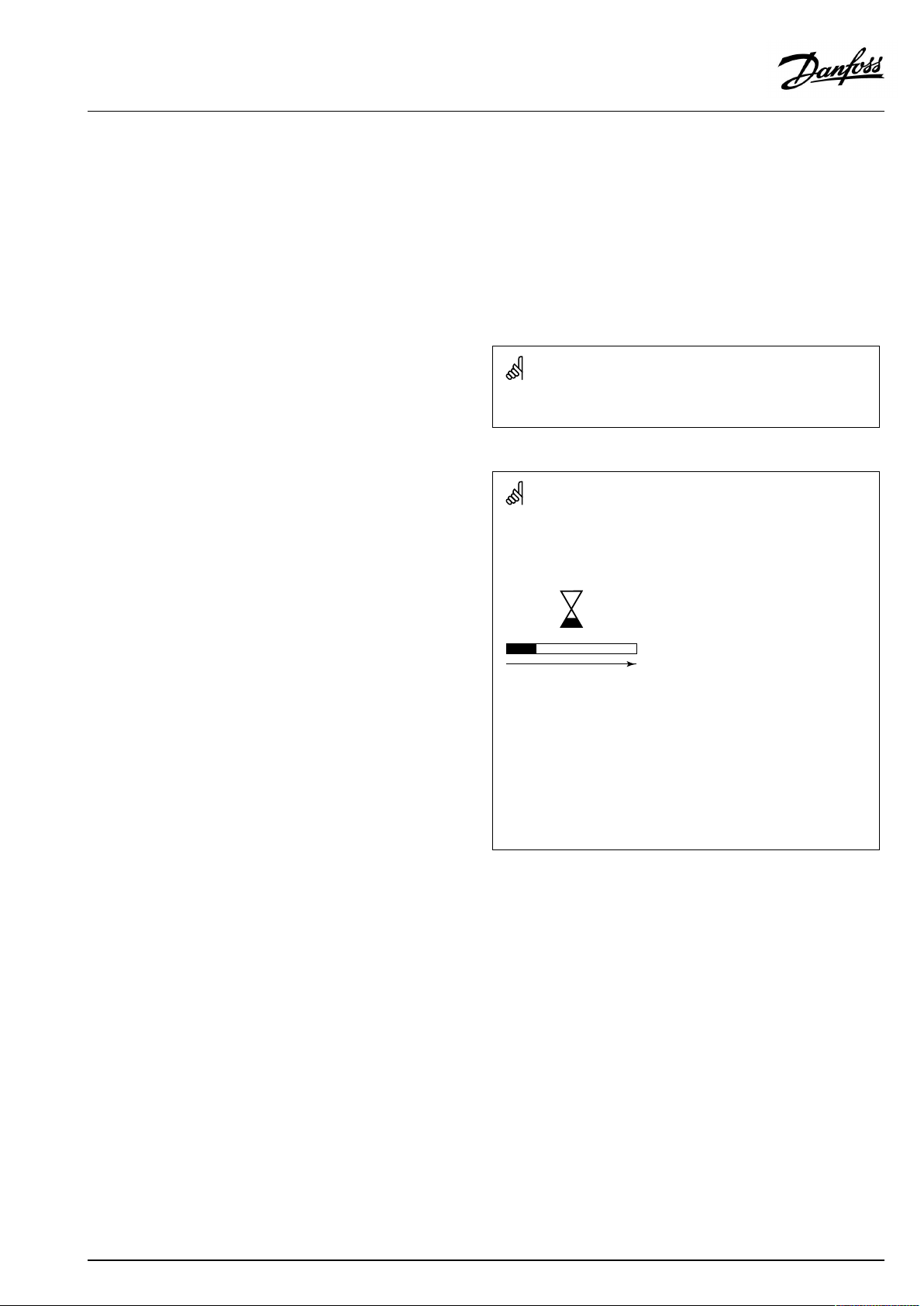
Automaticupdateofcontrollersoftware(firmware):
Thesoftwareofthecontrollerisupdatedautomaticallywhenthekey
isinserted(asofcontrollerversion1.11(ECL210/310)andversion
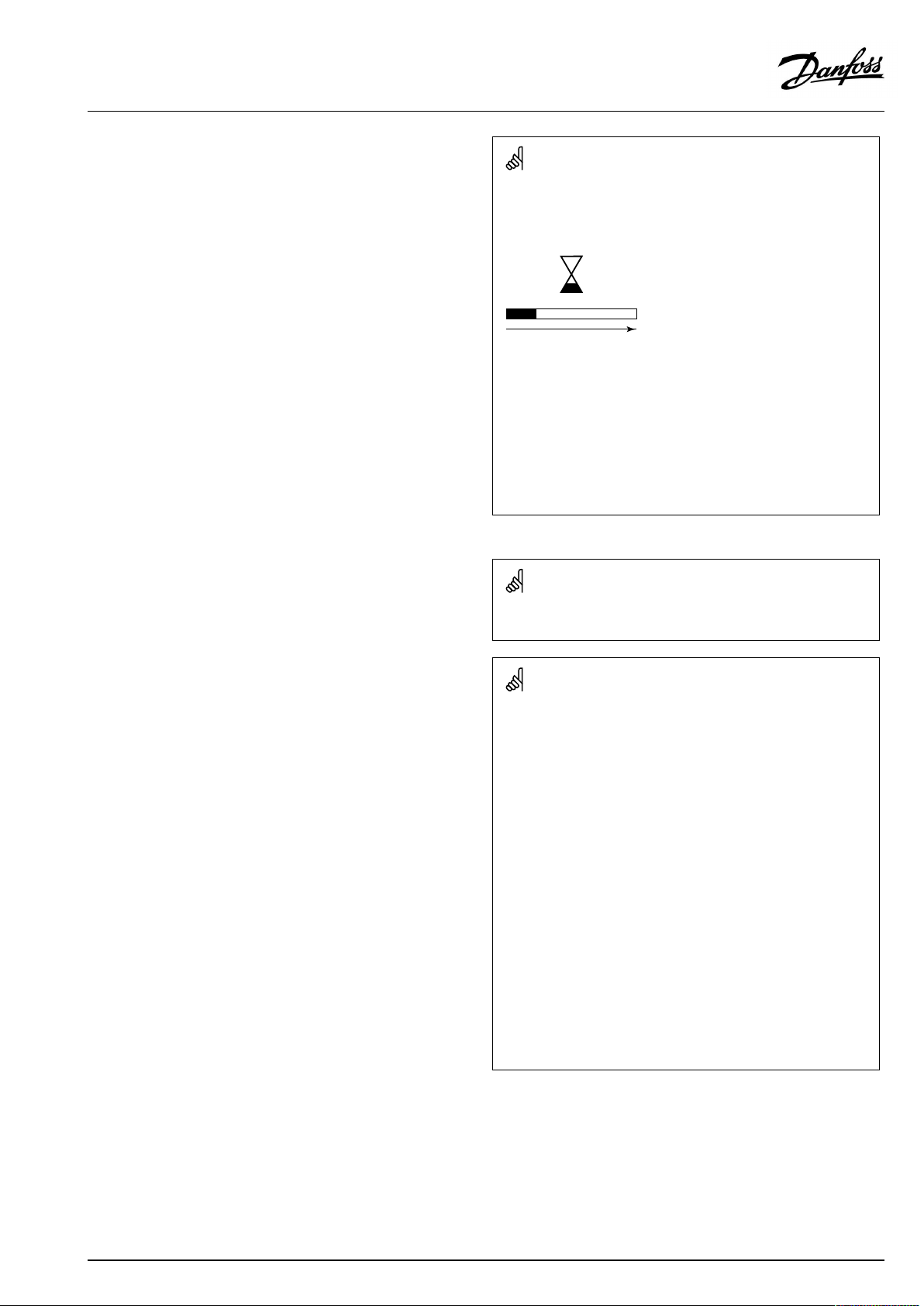
1.58(ECL296)).Thefollowinganimationwillbeshownwhenthe
softwareisbeingupdated:
Progressbar
Duringupdate:
•DonotremovetheKEY
Ifthekeyisremovedbeforethehour-glassisshown,youhave
tostartafresh.
•Donotdisconnectthepower
Ifthepowerisinterruptedwhenthehour-glassisshown,the
controllerwillnotwork.
•Manualupdateofcontrollersoftware(firmware):
Seethesection"Automatic/manualupdateoffirmware"
AQ152886470424en-010601
©Danfoss|2021.06|3
Page 4
OperatingGuideECLComfort310,applicationA319
SafetyNote
Toavoidinjuryofpersonsanddamagestothedevice,itisabsolutely
necessarytoreadandobservetheseinstructionscarefully.
Necessaryassembly,start-up,andmaintenanceworkmustbe
performedbyqualifiedandauthorizedpersonnelonly.
Locallegislationsmustberespected.Thiscomprisesalsocable
dimensionsandtypeofisolation(doubleisolatedat230V).
AfusefortheECLComfortinstallationismax.10Atypically.
TheambienttemperaturerangesforECLComfortinoperationare:
ECLComfort210/310:0-55°C
ECLComfort296:0-45°C.
Exceedingthetemperaturerangecanresultinmalfunctions.
Installationmustbeavoidedifthereisariskforcondensation(dew).
Thewarningsignisusedtoemphasizespecialconditionsthatshould
betakenintoconsideration.
Thissymbolindicatesthatthisparticularpieceofinformationshould
bereadwithspecialattention.
AsthisOperatingGuidecoversseveralsystemtypes,specialsystem
settingswillbemarkedwithasystemtype.Allsystemtypesareshown
inthechapter:'Identifyingyoursystemtype'.
°C(degreesCelsius)isameasuredtemperaturevaluewhereasK
(Kelvin)oftenisusedfortemperaturedifferences.
TheIDno.isuniquefortheselectedparameter.
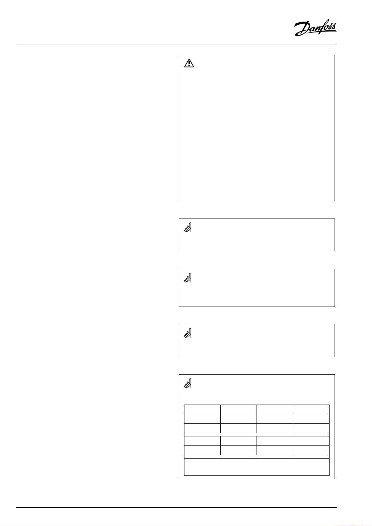
ExampleFirstdigitSeconddigitLastthreedigits
1117411174
-
Circuit1Parameterno.
4|©Danfoss|2021.06
12174
IfanIDdescriptionismentionedmorethanonce,itmeansthatthere
arespecialsettingsforoneormoresystemtypes.Itwillbemarked
withthesystemtypeinquestion(e.g.12174-A266.9).
1
-
2
Circuit2Parameterno.
174
AQ152886470424en-010601
Page 5
OperatingGuideECLComfort310,applicationA319
ParametersindicatedwithanIDno.like"1x607"meanauniversal
parameter.
xstandsforcircuit/parametergroup.
DisposalNote
Thissymbolontheproductindicatesthatitmaynot
bedisposedofashouseholdwaste.
Itmustbehandedovertotheapplicabletake-back
schemefortherecyclingofelectricalandelectronic
equipment.
•Disposeoftheproductthroughchannelsprovided
forthispurpose.
•Complywithalllocalandcurrentlyapplicablelaws
andregulations.
AQ152886470424en-010601
©Danfoss|2021.06|5
Page 6
OperatingGuideECLComfort310,applicationA319
2.0Installation
2.1Beforeyoustart
TheECLapplicationkeyA319contains2subtypes:A319.1and
A319.2.
Theseheatingbasedapplicationsareveryflexible.
ThebasicprinciplesforapplicationA319.1:
Temperaturecontrolofbuffer
ThebuffertemperatureS6isadjustedaccordingtoyour
requirements.ThesupplytemperaturesensorS2,thebuffer
temperaturesensorsS6andS8andthechargingtemperature
sensorS3arethemostimportantsensorsandmustbeconnected.
ThedesiredbuffertemperatureatS6iscalculatedintheECL
controller,basedonthedemandfromtheheatingcircuit
(consumer).ThisdemandisaresultoftheoutdoortemperatureS1,
theheatcurveandadesiredroomtemperature.Acompensation
fortheheatlossbetweenbuffertankandconsumercanbeset
as"Demandoffset" .
ThechargingtemperatureatS3isbasedonthedesiredbuffer
temperatureatS6andachargingdifference.
Startbufferchargingprocess:
1.BuffertemperatureS6temperaturegetslowerthan('Desired
buffertemperature'+'Startdifference').
Anexample:60°C+(-7)=53°C
2.X1isswitchedON
3.M1opensinordertoincreasethesupplytemperatureS2
4.P2isswitchedONwhensupplytemperatureS2getshigher
than('Desiredbuffertemperature'+'Pumpstartdiff. ').
Example:60°C+3K=63°C
V2startswithminimumspeed,forexample20%
5.M1controlsthechargingtemperatureatS3
6.V2increasesthespeedaslongasthechargingtemperatureis
equaltothedesiredchargingtemperature.
Stopbufferchargingprocess:
1.BuffertemperatureS6temperaturegetshigherthan('Desired
buffertemperature'+'Startdifference)
AND
LowerbuffertemperatureS8getshigherthan('Desiredbuffer
temperature'+'Stopdifference).
Anexample:S6temperaturehigherthan(60°C+(-7)=53°C)
AND(60°C+(-4)=56°C)
2.P2isswitchedOFF ,respecting'Char.Ppost-run'.V2changes
to0%.
NOTE:Post-runisnotrespectedifchargingtemperatureS3islower
thandesiredchargingtemperature.
3.X1isswitchedOFF
4.M1closesormaintainsthedesiredtemperatureatS3.
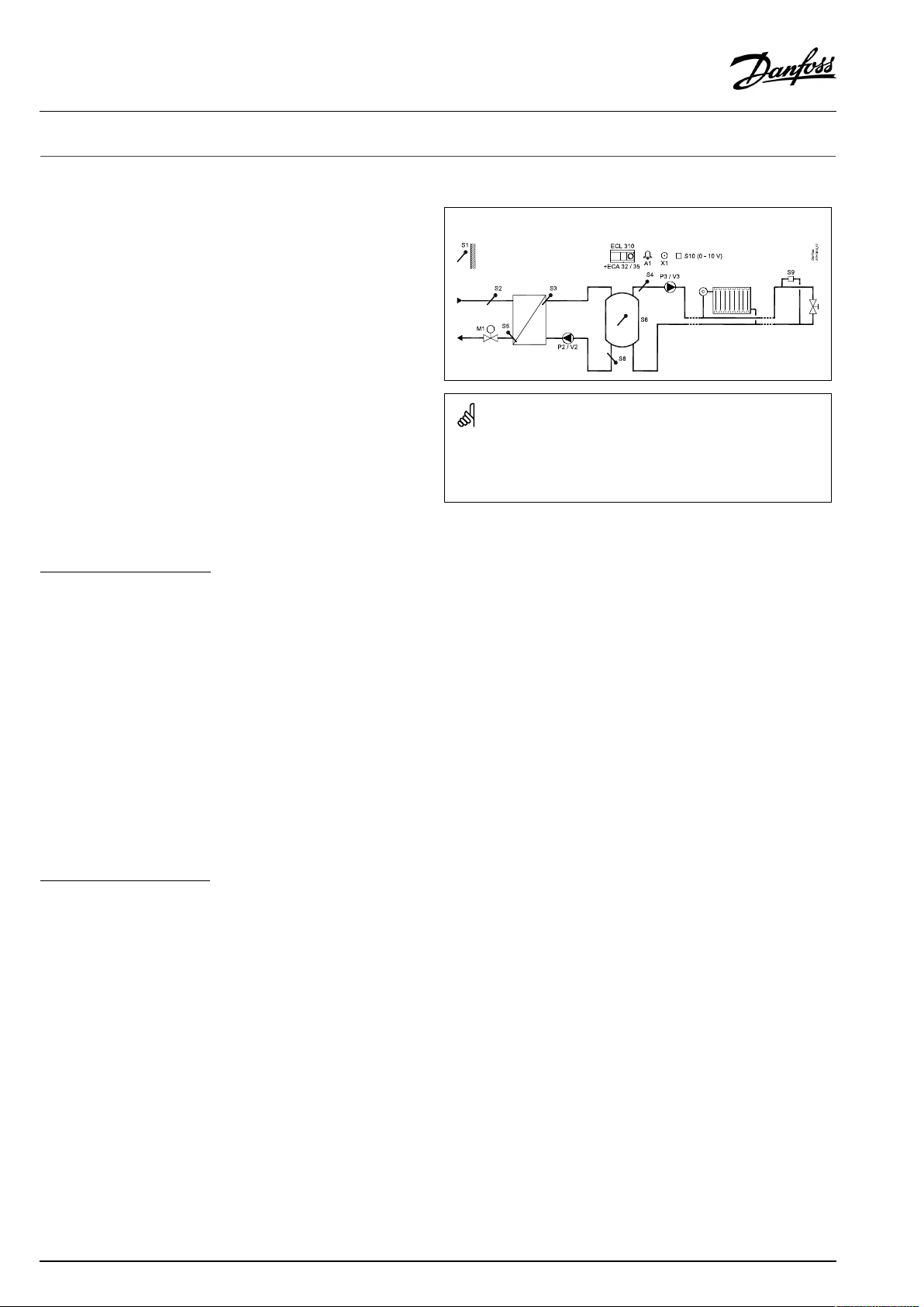
TypicalA319.1application:
Theshowndiagramisafundamentalandsimplifiedexampleanddoes
notcontainallcomponentsthatarenecessaryinasystem.
AllnamedcomponentsareconnectedtotheECLComfortcontroller.
Listofcomponents:
ECL310
ECA32
ECA35
S1
S2
S3
S4
S5Returntemperaturesensor
S6
S7
S8
S9
S10
P2
V2
P3
V3
M1
X1
A1
ECLComfort310controller
Built-inextensionmodule,0-10Voutputs
Built-inextensionmodule,0-10Voutputsand
PWMoutputs
Outdoortemperaturesensor
(mandatory)Supplytemperaturesensor
(mandatory)Chargingtemperaturesensor
(monitoringonly)Flowtemperaturesensor
(mandatory)Upperbuffertemperaturesensor
notused
(mandatory)Lowerbuffertemperaturesensor
Pressuredifferencetransmitter(0-10V)
0-10VinputfordesiredtemperatureatS6
Chargingpump(ON-OFFcontrolled)
Speedcontrolofchargingpump(0-10VorPWM)
Circulationpump(ON-OFFcontrolled)
Speedcontrolofcirculationpump(0-10Vor
PWM)
Motorizedcontrolvalve(3-pointcontrolled)
Heatdemandsignal
Alarm
6|©Danfoss|2021.06
AQ152886470424en-010601
Page 7

OperatingGuideECLComfort310,applicationA319
Bymeansofaweekschedule,thecircuitcanbein‘Comfort’or
‘Saving’mode(twovaluesforthedesiredroomtemperature).In
'Saving'modetheheatingcanbereducedorswitchedofftotally.
Themotorizedcontrolvalve(M1)isopenedgraduallywhen
thechargingtemperatureislowerthanthedesiredcharging
temperatureandviceversa.
ThereturntemperatureS5canbelimited,forexamplenottobe
toohigh.Ifso,thedesiredchargingtemperatureatS3canbe
adjusted(typicallytoalowervalue);thisresultsinagradualclosing
ofthemotorizedcontrolvalve.
Furthermore,thereturntemperaturelimitationcanbedependent
ontheoutdoortemperature.Typically,thelowertheoutdoor
temperature,thehighertheacceptedreturntemperature.
TheON-OFFoutputX1isONatheatingdemand.
ThecirculationpumpP3isONatheatingdemandoratfrost
protection.
Unusedinputcan,bymeansofanoverrideswitchorrelaycontact,
beusedforoverridingthescheduletoafixed'Comfort' ,'Saving',
'Frostprotection'or'Constanttemperature'mode.
UptotwoRemoteControlUnits,ECA30/31canbeconnectedto
oneECLcontrollerinordertocontroltheECLcontrollerremotely.
The'Frostprotection'modemaintainsaselectabletemperature,
forexample10°C.
AdditionalECLComfortcontrollerscanbeconnectedviatheECL
485businordertoutilizecommonoutdoortemperaturesignal,
timeanddatesignals.TheECLControllersintheECL485bus
systemcanworkasmasterandslaves.
AlarmA1(=relay6)canbeactivatedif:
•theactualchargingtemperaturediffersfromthedesiredcharge
temperature
•thesupplytemperaturedoesnotreachthenecessarylevel
•atemperaturesensororitsconnectiondisconnects/short
circuits.(See:Commoncontrollersettings>System>Raw
inputoverview)
Pressuredifferencecontrol(optional):
ThecirculationpumpP3/V3can,asanalternativetoON-OFF
control,bespeedcontrolledbymeansofa0-10voltsignalora
PWMsignal.ThedesiredpressuredifferenceatS9canbesetforthe
speedcontrolprocedure.
AQ152886470424en-010601
©Danfoss|2021.06|7
Page 8
OperatingGuideECLComfort310,applicationA319
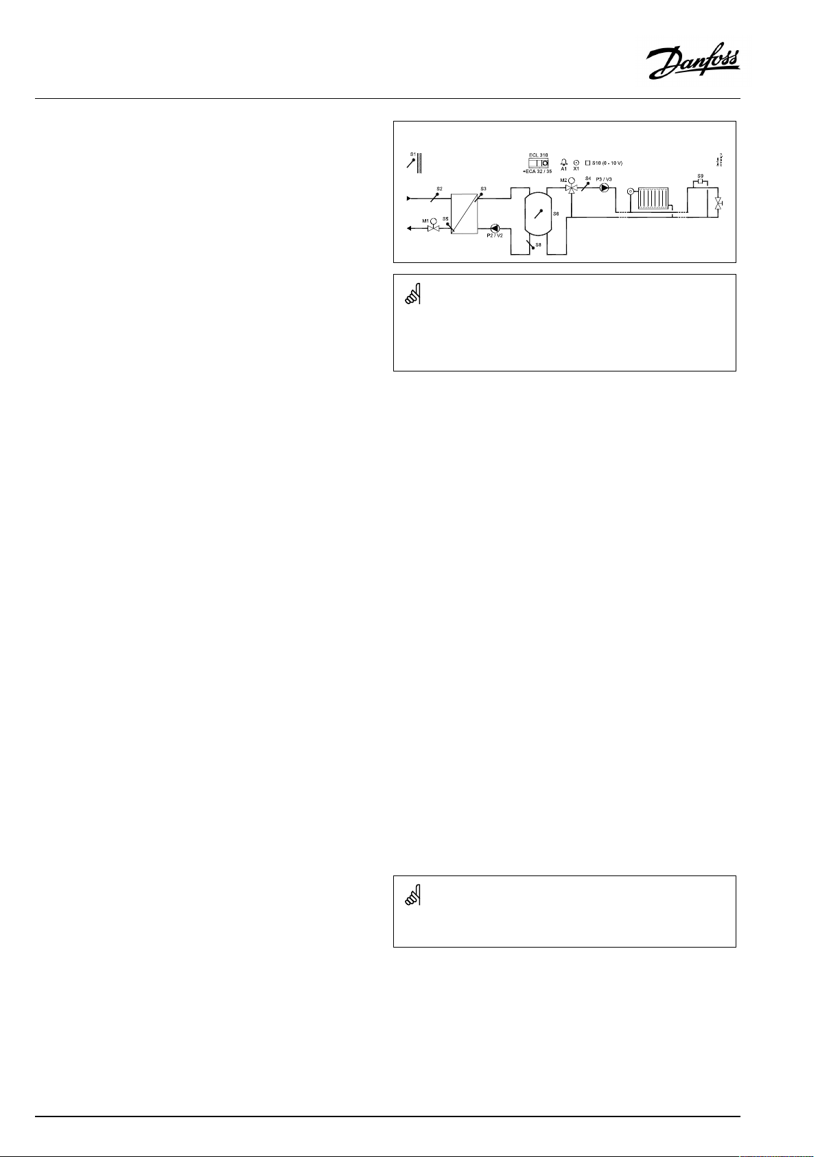
ThebasicprinciplesforapplicationA319.2:
TheapplicationA319.2workslikeA319.1andwiththeseadditional
features:
Themotorizedcontrolvalve(M2)isopenedgraduallywhenthe
flowtemperatureS4islowerthanthedesiredflowtemperature
andviceversa.
TypicalA319.2application:
Theshowndiagramisafundamentalandsimplifiedexampleanddoes
notcontainallcomponentsthatarenecessaryinasystem.
AllnamedcomponentsareconnectedtotheECLComfortcontroller.
Listofcomponents:
ECL310
ECA32
ECA35
ECLComfort310controller
Built-inextensionmodule,0-10Voutputs
Built-inextensionmodule,0-10Voutputsand
PWMoutputs
S1
S2
S3
S4
Outdoortemperaturesensor
(mandatory)Supplytemperaturesensor
(mandatory)Chargingtemperaturesensor
(mandatory)Flowtemperaturesensor
S5Returntemperaturesensor
S6
S8
S9
S10
P2
V2
P3
V3
(mandatory)Upperbuffertemperaturesensor
(mandatory)Lowerbuffertemperaturesensor
Pressuredifferencetransmitter(0-10V)
0-10VinputfordesiredtemperatureatS6
Chargingpump(ON-OFFcontrolled)
Speedcontrolofchargingpump(0-10VorPWM)
Circulationpump(ON-OFFcontrolled)
Speedcontrolofcirculationpump(0-10Vor
PWM)
M1
M2
X1
A1
Motorizedcontrolvalve(3-pointcontrolled)
Motorizedcontrolvalve(3-pointcontrolled)
Heatdemandsignal
Alarm
8|©Danfoss|2021.06
Thecontrollerispre-programmedwithfactorysettingsthatareshown
inthe‘ParameterIDoverview’appendix.
AQ152886470424en-010601
Page 9
OperatingGuideECLComfort310,applicationA319
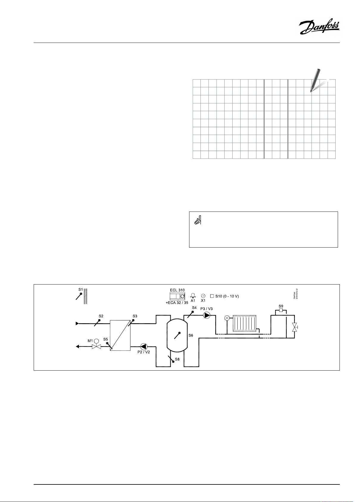
2.2Identifyingthesystemtype
Sketchyourapplication
TheECLComfortcontrollerseriesisdesignedforawiderange
ofheating,domestichot-water(DHW)andcoolingsystemswith
differentconfigurationsandcapacities.Ifyoursystemdiffers
fromthediagramsshownhere,youmaywanttomakeasketch
ofthesystemabouttobeinstalled.Thismakesiteasiertouse
theOperatingGuide,whichwillguideyoustep-by-stepfrom
installationtofinaladjustmentsbeforetheend-usertakesover.
TheECLComfortcontrollerisauniversalcontrollerthatcanbe
usedforvarioussystems.Basedontheshownstandardsystems,
itispossibletoconfigureadditionalsystems.Inthischapteryou
findthemostfrequentlyusedsystems.Ifyoursystemisnotquite
asshownbelow,findthediagramwhichhasthebestresemblance
withyoursystemandmakeyourowncombinations.
SeetheInstallationGuide(deliveredwiththeapplicationkey)for
applicationtypes/sub-types.
Thecirculationpump(s)inheatingcircuit(s)canbeplacedintheflow
aswellasthereturn.Placethepumpaccordingtothemanufacturer’s
specification.
A319.1,ex.a
Chargingcontrolofbuffertemperatureandheatingsupplydirectlyfrombuffer.Controlofpressuredifference.
Sensoradvice:
SensorS3,S6andS8mustbeconnected.Ifnot,thechargingprocesswillnotwork.
IfpressuredifferencesensorS9isnotconnected,thespeedcontrolofP3/V3isnotinaction.
AQ152886470424en-010601
©Danfoss|2021.06|9
Page 10
OperatingGuideECLComfort310,applicationA319
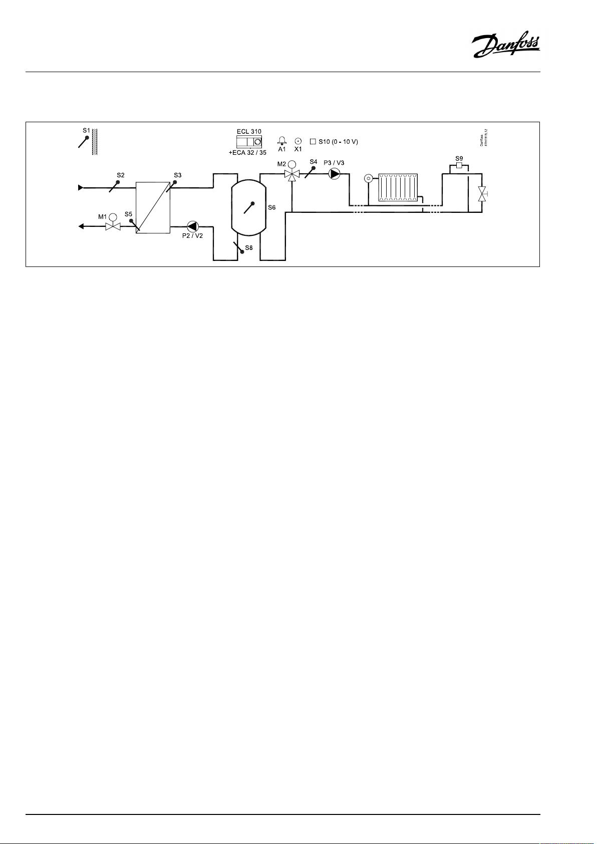
A319.2,ex.a
Chargingcontrolofbuffertemperatureandheatingsupplyfrombufferviamixingcircuit.Controlofpressuredifference.
Sensoradvice:
SensorS3,S4,S6andS8mustbeconnected.Ifnot,thechargingprocesswillnotwork.
IfpressuredifferencesensorS9isnotconnected,thespeedcontrolofP3/V3isnotinaction.
10|©Danfoss|2021.06
AQ152886470424en-010601
Page 11
OperatingGuideECLComfort310,applicationA319
2.3Mounting
2.3.1MountingtheECLComfortcontroller
SeetheInstallationGuidewhichisdeliveredtogetherwiththe
ECLComfortcontroller.
Foreasyaccess,youshouldmounttheECLComfortcontrollernear
thesystem.
ECLComfort210/296/310canbemounted
•onawall
•onaDINrail(35mm)
ECLComfort296canbemounted
•inapanelcut-out
ECLComfort210canbemountedinanECLComfort310basepart
(forfutureupgrade).
Screws,PGcableglandsandrawlplugsarenotsupplied.
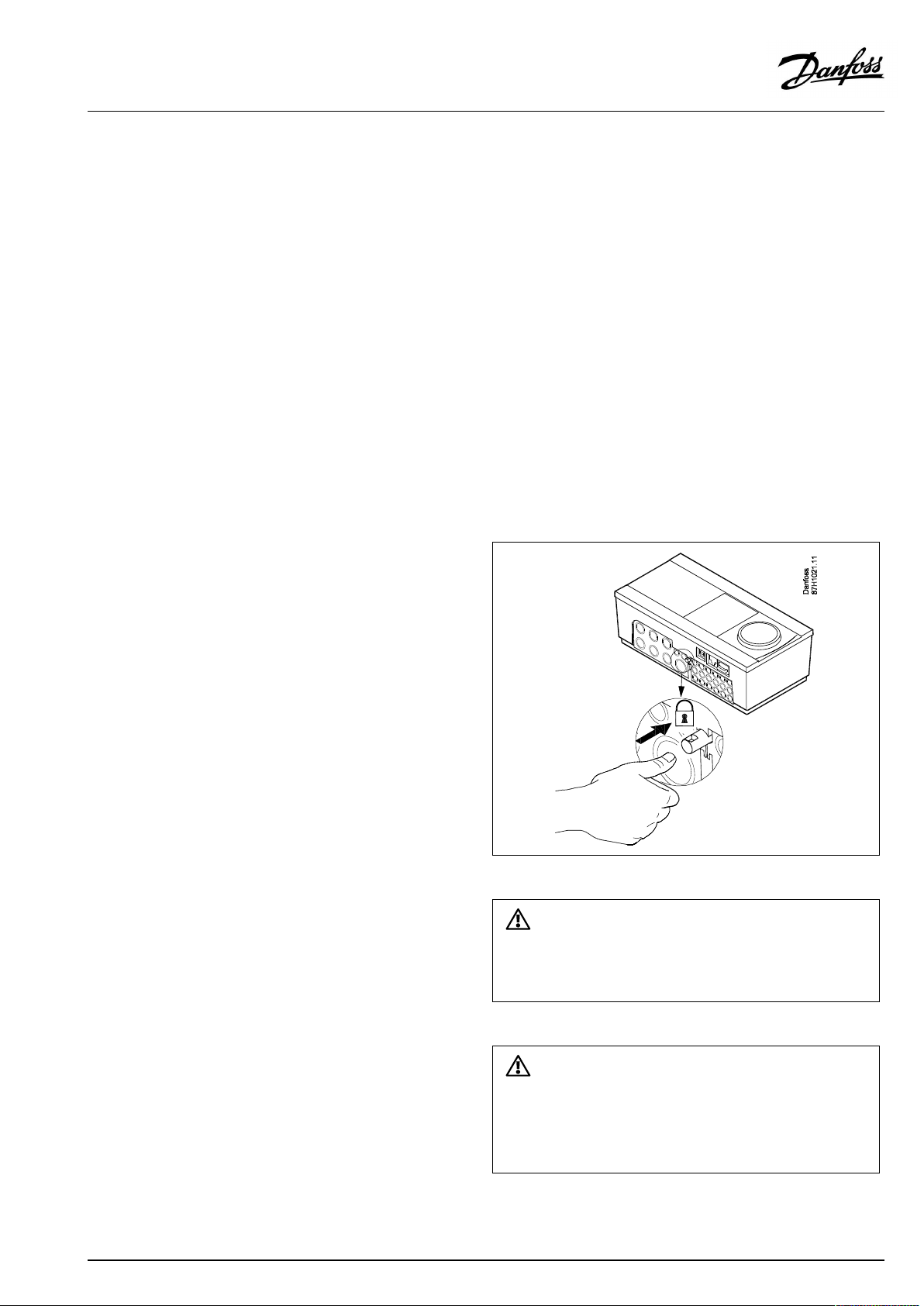
LockingtheECLComfort210/310controller
InordertofastentheECLComfortcontrollertoitsbasepart,secure
thecontrollerwiththelockingpin.
Topreventinjuriestopersonsorthecontroller,thecontrollerhasto
besecurelylockedintothebase.Forthispurpose,pressthelocking
pinintothebaseuntilaclickisheardandthecontrollernolonger
canberemovedfromthebase.
Ifthecontrollerisnotsecurelylockedintothebasepart,thereisarisk
thatthecontrollerduringoperationcanunlockfromthebaseandthe
basewithterminals(andalsothe230Va.c.connections)areexposed.
Topreventinjuriestopersons,alwaysmakesurethatthecontroller
issecurelylockedintoitsbase.Ifthisisnotthecase,thecontroller
shouldnotbeoperated!
AQ152886470424en-010601
©Danfoss|2021.06|11
Page 12
OperatingGuideECLComfort310,applicationA319
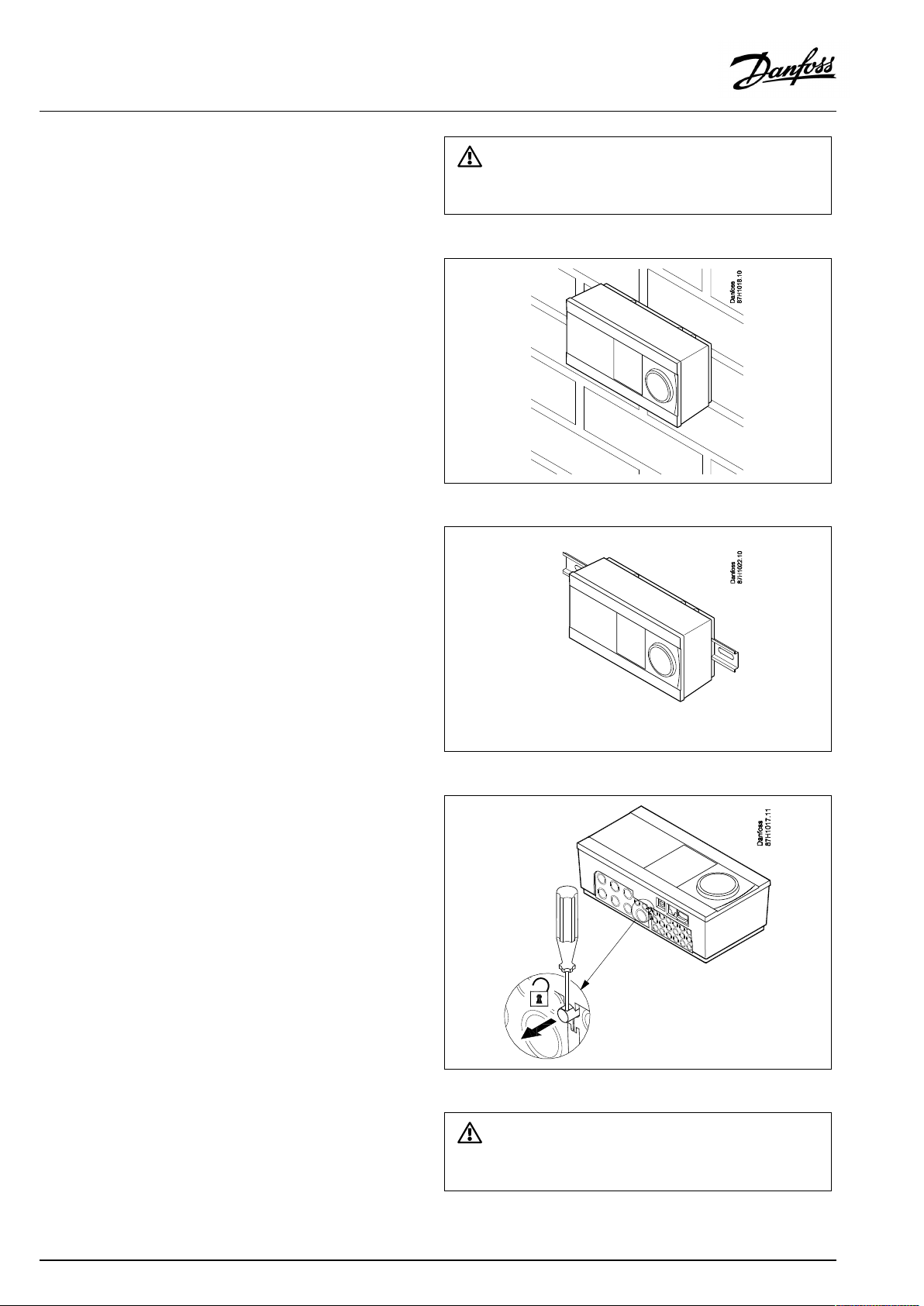
Mountingonawall
Mountthebasepartonawallwithasmoothsurface.Establishthe
electricalconnectionsandpositionthecontrollerinthebasepart.
Securethecontrollerwiththelockingpin.
MountingonaDINrail(35mm)
MountthebasepartonaDINrail.Establishtheelectrical
connectionsandpositionthecontrollerinthebasepart.Secure
thecontrollerwiththelockingpin.
Theeasywaytolockthecontrollertoitsbaseorunlockitistousea
screwdriveraslever.
DismountingtheECLComfortcontroller
Inordertoremovethecontrollerfromthebasepart,pulloutthe
lockingpinbymeansofascrewdriver.Thecontrollercannowbe
removedfromthebasepart.
Theeasywaytolockthecontrollertoitsbaseorunlockitistousea
screwdriveraslever.
12|©Danfoss|2021.06
AQ152886470424en-010601
Page 13
OperatingGuideECLComfort310,applicationA319
2.3.2MountingtheRemoteControlUnitsECA30/31
Selectoneofthefollowingmethods:
•Mountingonawall,ECA30/31
•Mountinginapanel,ECA30
Screwsandrawlplugsarenotsupplied.
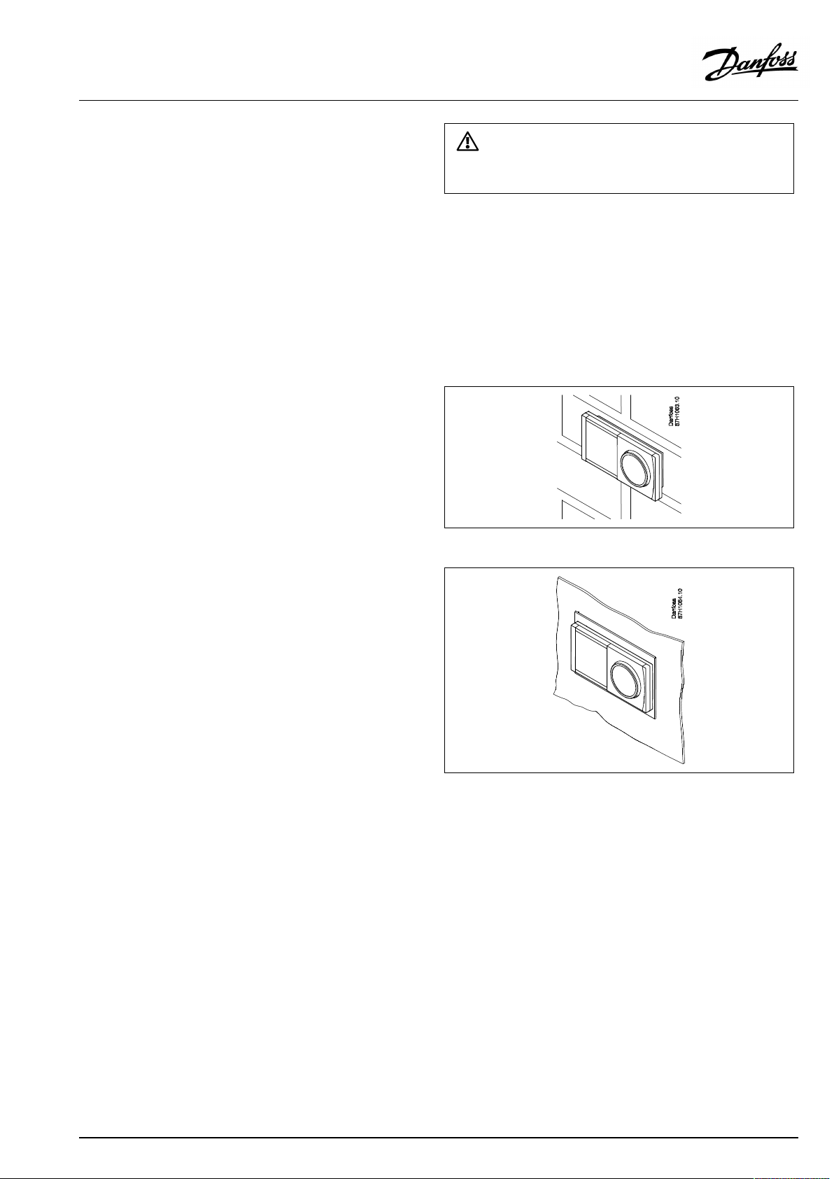
Mountingonawall
MountthebasepartoftheECA30/31onawallwithasmooth
surface.Establishtheelectricalconnections.PlacetheECA30/
31inthebasepart.
BeforeremovingtheECLComfortcontrollerfromthebasepart,ensure
thatthesupplyvoltageisdisconnected.
Mountinginapanel
MounttheECA30inapanelusingtheECA30framekit(ordercode
no.087H3236).Establishtheelectricalconnections.Securethe
framewiththeclamp.PlacetheECA30inthebasepart.TheECA
30canbeconnectedtoanexternalroomtemperaturesensor.
TheECA31mustnotbemountedinapanelifthehumidity
functionistobeused.
AQ152886470424en-010601
©Danfoss|2021.06|13
Page 14
OperatingGuideECLComfort310,applicationA319
2.3.3MountingtheinternalI/OmoduleECA32orECA35
TheECA32module(ordercodeno.087H3202)orECA35module
(ordercodeno.087H3205)canbeinsertedintotheECLComfort
310/310Bbasepartforadditionalinputandoutputsignalsin
relevantapplications.
ECA32
ECA35
14|©Danfoss|2021.06
AQ152886470424en-010601
Page 15
OperatingGuideECLComfort310,applicationA319
2.4Placingthetemperaturesensors
2.4.1Placingthetemperaturesensors
Itisimportantthatthesensorsaremountedinthecorrectposition
inyoursystem.
Thetemperaturesensormentionedbelowaresensorsusedforthe
ECLComfort210/296/310serieswhichnotallwillbeneeded
foryourapplication!
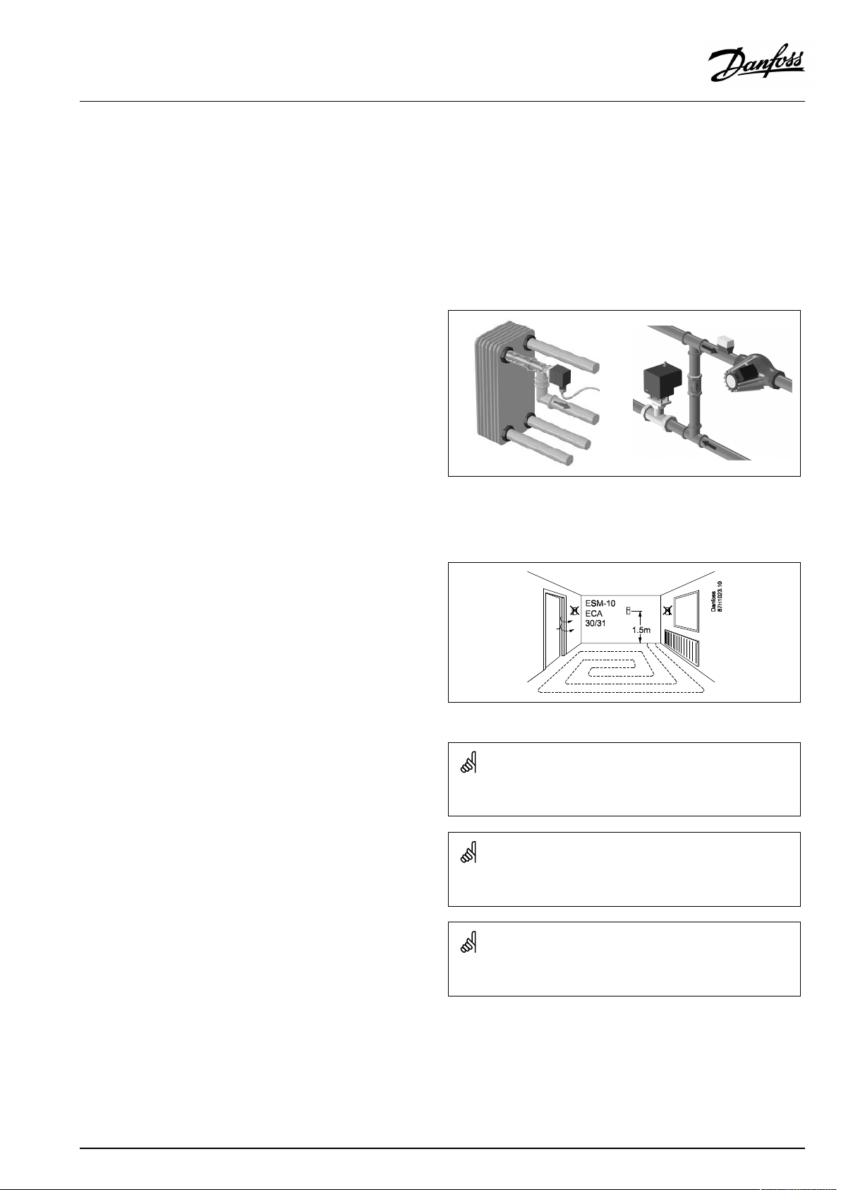
Outdoortemperaturesensor(ESMT)
Theoutdoorsensorshouldbemountedonthatsideofthebuilding
whereitislesslikelytobeexposedtodirectsunshine.Itshouldnot
beplacedclosetodoors,windowsorairoutlets.
Flowtemperaturesensor(ESMU,ESM-11orESMC)
Placethesensormax.15cmfromthemixingpoint.Insystems
withheatexchanger,DanfossrecommendsthattheESMU-typeto
beinsertedintotheexchangerflowoutlet.
Makesurethatthesurfaceofthepipeiscleanandevenwhere
thesensorismounted.
Returntemperaturesensor(ESMU,ESM-11orESMC)
Thereturntemperaturesensorshouldalwaysbeplacedsothatit
measuresarepresentativereturntemperature.
Roomtemperaturesensor
(ESM-10,ECA30/31RemoteControlUnit)
Placetheroomsensorintheroomwherethetemperatureistobe
controlled.Donotplaceitonoutsidewallsorclosetoradiators,
windowsordoors.
Boilertemperaturesensor(ESMU,ESM-11orESMC)
Placethesensoraccordingtotheboilermanufacturer’s
specification.
Airducttemperaturesensor(ESMB-12orESMUtypes)
Placethesensorsothatitmeasuresarepresentativetemperature.
DHWtemperaturesensor(ESMUorESMB-12)
PlacetheDHWtemperaturesensoraccordingtothemanufacturer’s
specification.
Slabtemperaturesensor(ESMB-12)
Placethesensorinaprotectiontubeintheslab.
ESM-11:Donotmovethesensorafterithasbeenfastenedinorderto
avoiddamagetothesensorelement.
ESM-11,ESMCandESMB-12:Useheatconductingpasteforquick
measurementofthetemperature.
ESMUandESMB-12:Usingasensorpockettoprotectthesensorwill,
however,resultinaslowertemperaturemeasurement.
AQ152886470424en-010601
©Danfoss|2021.06|15
Page 16
OperatingGuideECLComfort310,applicationA319
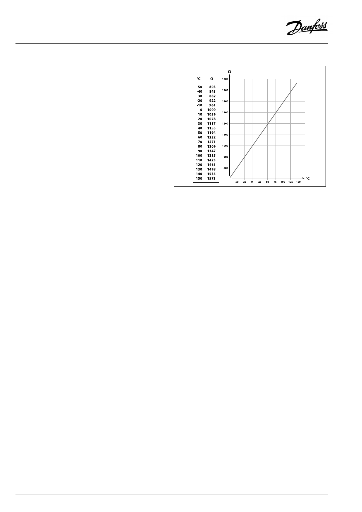
Pt1000temperaturesensor(IEC751B,1000Ω/0°C)
Relationshipbetweentemperatureandohmicvalue:
16|©Danfoss|2021.06
AQ152886470424en-010601
Page 17
OperatingGuideECLComfort310,applicationA319
2.5Electricalconnections
2.5.1Electricalconnections230Va.c.
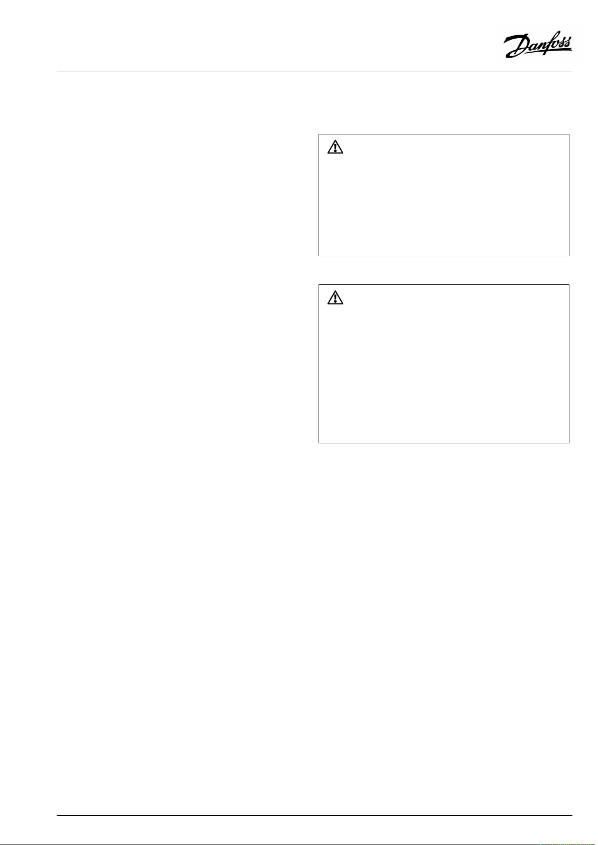
Warning
ElectricconductorsonPCB(PrintedCircuitBoard)forsupplyvoltage,
relaycontactsandtriacoutputsdonothavemutualsafetydistanceof
minimum6mm.Theoutputsarenotallowedtobeusedasgalvanic
separated(voltfree)outputs.
Ifagalvanicseparatedoutputisneeded,anauxiliaryrelayis
recommended.
24Voltcontrolledunits,forexampleactuators,aretobecontrolledby
meansofECLComfort310,24Voltversion.
SafetyNote
Necessaryassembly,start-up,andmaintenanceworkmustbe
performedbyqualifiedandauthorizedpersonnelonly.
Locallegislationsmustberespected.Thiscomprisesalsocablesize
andisolation(reinforcedtype).
AfusefortheECLComfortinstallationismax.10Atypically.
TheambienttemperaturerangefortheECLComfortinoperationis
0-55°C.Exceedingthistemperaturerangecanresultinmalfunctions.
Installationmustbeavoidedifthereisariskforcondensation(dew).
AQ152886470424en-010601
©Danfoss|2021.06|17
Page 18
OperatingGuideECLComfort310,applicationA319
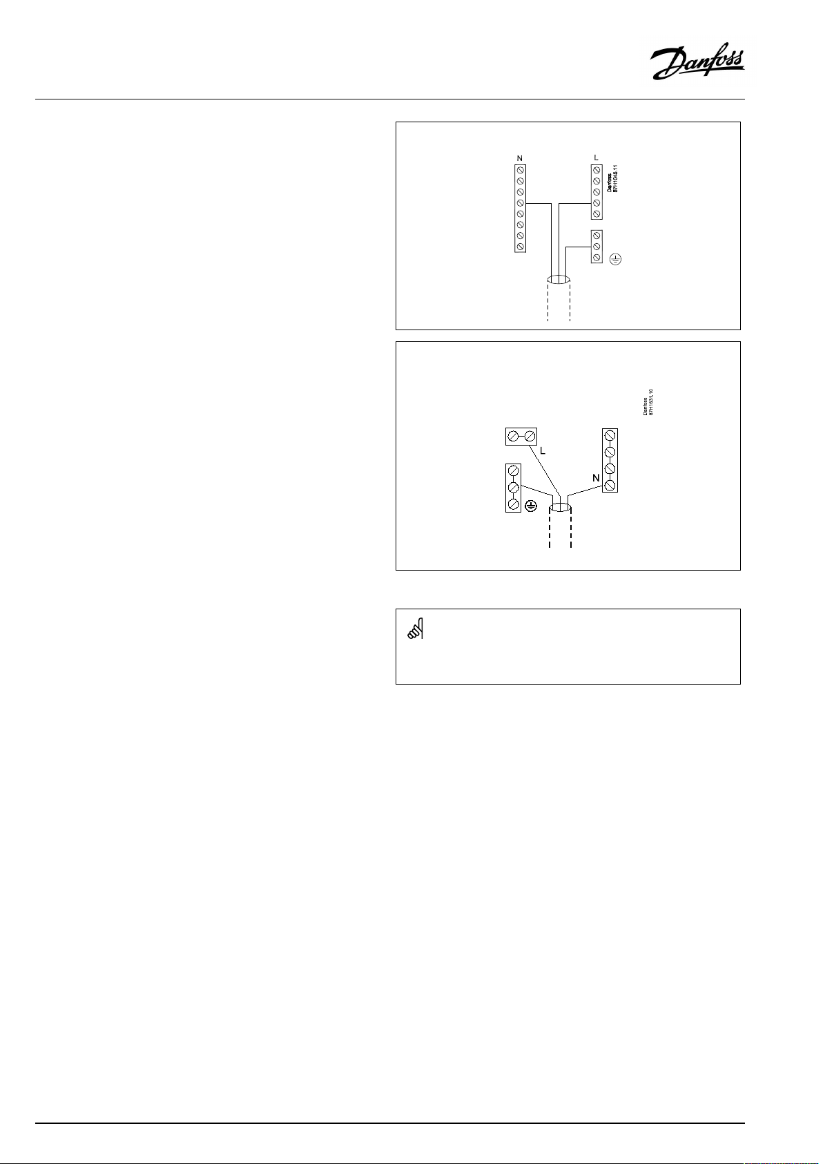
Thecommongroundterminalisusedforconnectionofrelevant
components(pumps,motorizedcontrolvalves).
ECL210/310
ECL296
Factoryestablishedjumpersinthebasepart:
5to8,9to14,Lto5andLto9,Nto10
18|©Danfoss|2021.06
AQ152886470424en-010601
Page 19
OperatingGuideECLComfort310,applicationA319
2.5.2Electricalconnections,230Va.c.,powersupply,pumps,motorizedcontrolvalvesetc.
Connections,ingeneral.
SeealsotheInstallationGuide(deliveredwiththeapplicationkey)forapplicationspecificconnections.
Maximumloadratings:
Relayterminals
4(2)A/230Va.c.
(4Aforohmicload,2Aforinductiveload)
Triac(electronicrelay)terminals
0,2A/230Va.c.
Wirecrosssection:0.5-1.5mm²
Incorrectconnectioncandamagetheelectronicoutputs.
Max.2x1.5mm²wirescanbeinsertedintoeachscrewterminal.
2.5.3Electricalconnections,24Va.c.,powersupply,pumps,motorizedcontrolvalvesetc.
Connections,ingeneral.
SeealsotheInstallationGuide(deliveredwiththeapplicationkey)forapplicationspecificconnections.
Maximumloadratings:
Relayterminals
4(2)A/24Va.c.
(4Aforohmicload,2Aforinductiveload)
Triac(electronicrelay)terminals
1A/24Va.c.
Donotconnect230Va.c.poweredcomponentstoa24Va.c.power
suppliedcontrollerdirectly.Useauxilliaryrelays(K)toseparate230
Va.c.from24Va.c.
Wirecrosssection:0.5-1.5mm²
Incorrectconnectioncandamagetheelectronicoutputs.
Max.2x1.5mm²wirescanbeinsertedintoeachscrewterminal.
AQ152886470424en-010601
©Danfoss|2021.06|19
Page 20

OperatingGuideECLComfort310,applicationA319
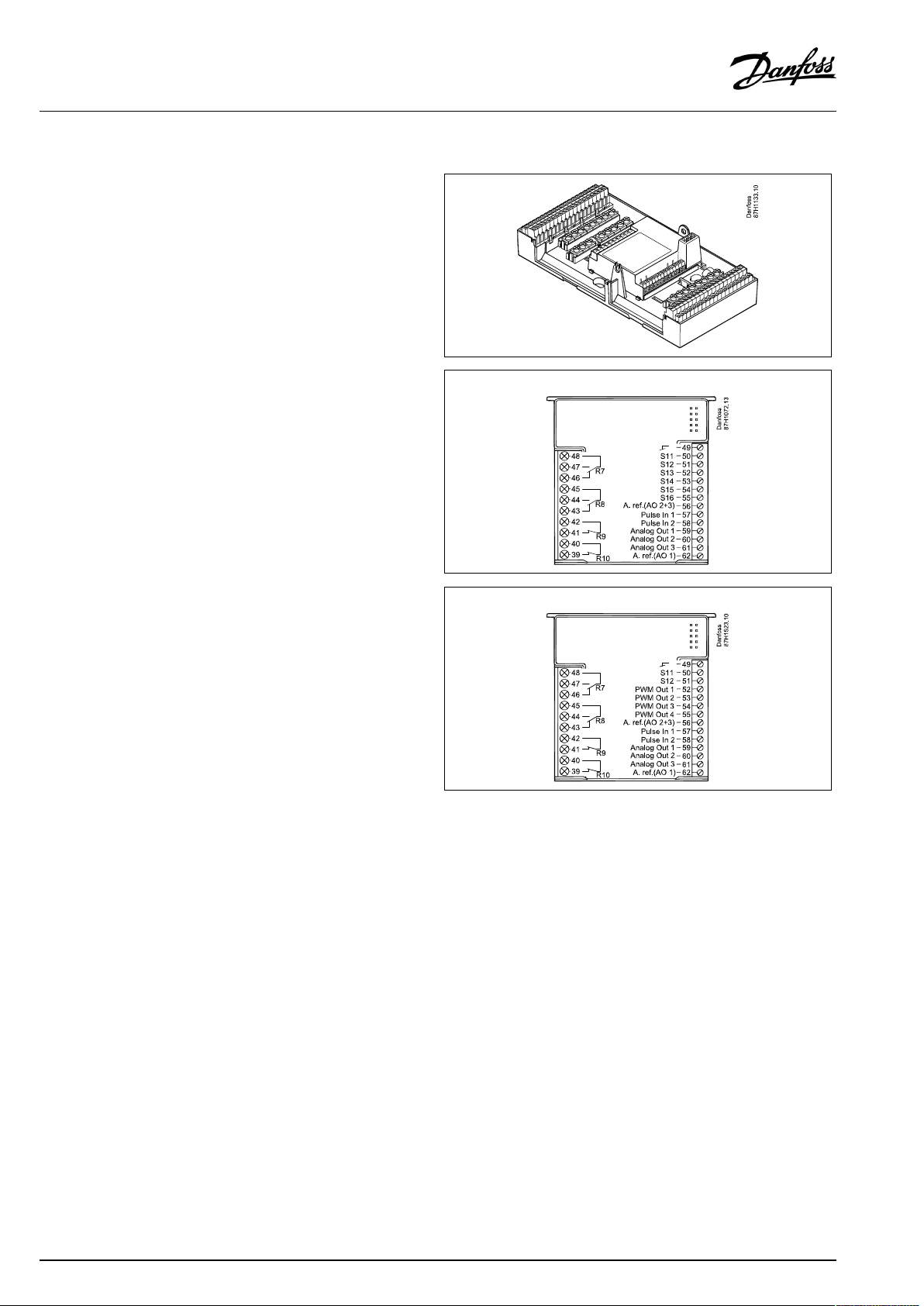
Electricalconnections,ECA32/ECA35
Connections,ingeneral.
SeealsotheInstallationGuide(deliveredwiththeapplicationkey)forapplicationspecificconnections.
Maximumloadratings:
Terminals
ECA32ECA35
PWMOut1(52)
PWMOut2(53)
PWMOut3(54)
PWMOut4(55)
AnalogOut1(59)AnalogOut1(59)47kΩ*
AnalogOut2(60)AnalogOut2(60)47kΩ*
AnalogOut3(61)AnalogOut3(61)47kΩ*
*Thevalueisaminimum.
5kΩ*
5kΩ*
5kΩ*
5kΩ*
20|©Danfoss|2021.06
AQ152886470424en-010601
Page 21
OperatingGuideECLComfort310,applicationA319
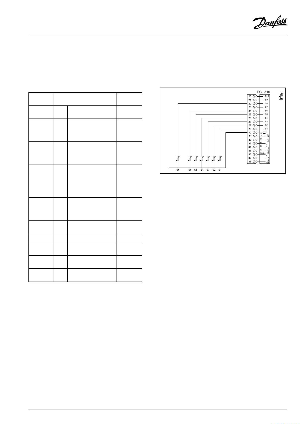
2.5.4Electricalconnections,Pt1000temperaturesensors
SeealsotheInstallationGuide(deliveredwiththeapplicationkey)
forapplicationspecificconnections.
A319
TerminalSensor/description
29and30
28and30
27and30
26and30
25and30
24and30
23and30
22and30
21and30
20and30
S1
Outdoortemperature
sensor*
S2
Supplytemperature
sensor
S3
Chargingtemperature
sensor**
A319.1:
S4
Flowtemperature
sensor,monitoring
A319.2:
Flowtemperature
sensor
S5Returntemperature
sensor
S6
Upperbuffer-tank
temperaturesensor
S7
notused
S8
Upperbuffer-tank
temperaturesensor
S9
Pressuredifference
transmitter(0-10V)
S10
0-10Voltasdesired
temperature
Type
(recom.)
ESMT
ESM-11/
ESMB/
ESMC/
ESMU
ESM-11/
ESMB/
ESMC/
ESMU
ESM-11/
ESMB/
ESMC/
ESMU
ESM-11/
ESMB/
ESMC/
ESMU
ESMB/
ESMU
ESMB/
ESMU
Temperaturesensorsmustbeconnectedinordertohavethe
desiredfunctionality.
*
Iftheoutdoortemperaturesensorisnotconnectedorthe
sensorcableisshort-circuited,thecontrollerassumesthat
theoutdoortemperatureis0(zero)°C.
**
Ifthesensorisnotconnectedorthesensorcableis
short-circuited,themotorizedcontrolvalvecloses(safety
function).
Factoryestablishedjumper:
30tocommonterminal.
AQ152886470424en-010601
©Danfoss|2021.06|21
Page 22
OperatingGuideECLComfort310,applicationA319
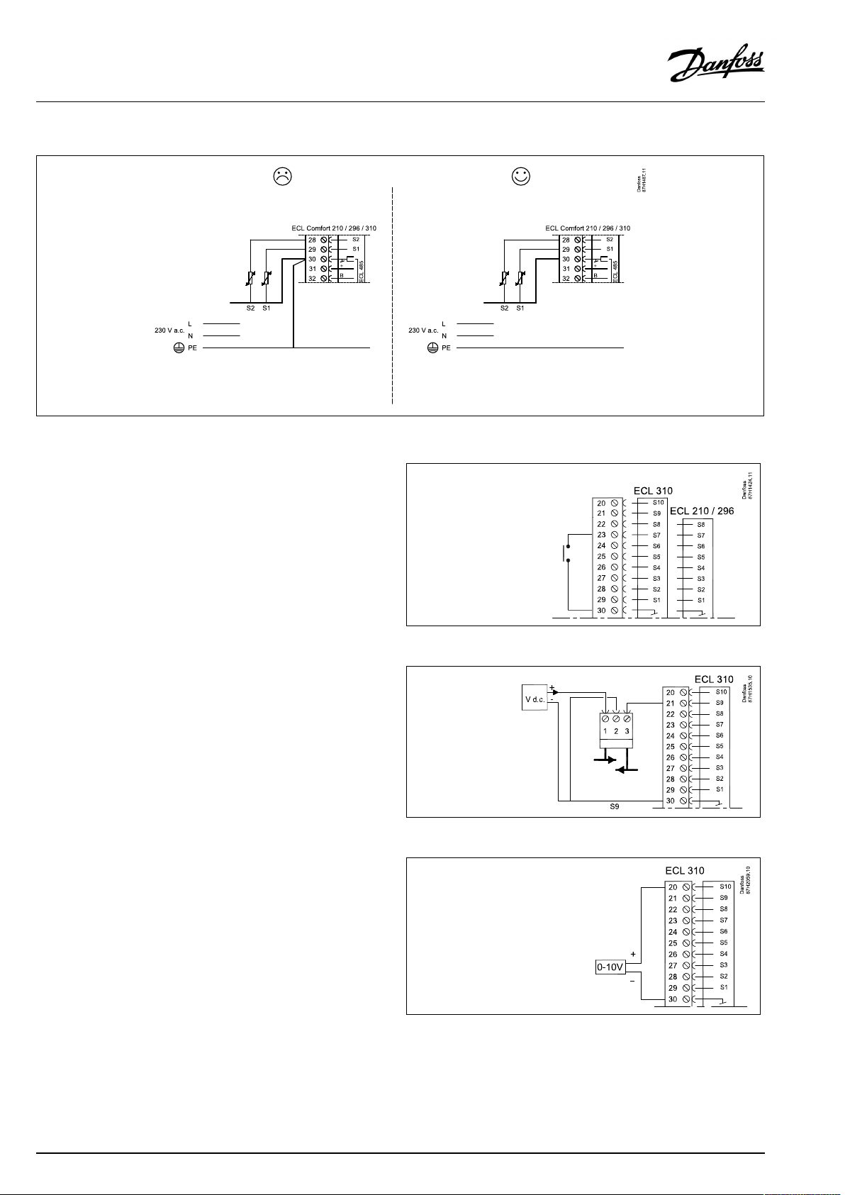
Inputconnnections
Exampleofoverridecontact,connectedtoS7:
(ignoreECL210)
ConnectionofinputS9:
Pressuredifferencetransmitter,0-10Volt
ConnectionofinputS10:
Controlvoltagefordesiredtemperature
22|©Danfoss|2021.06
AQ152886470424en-010601
Page 23
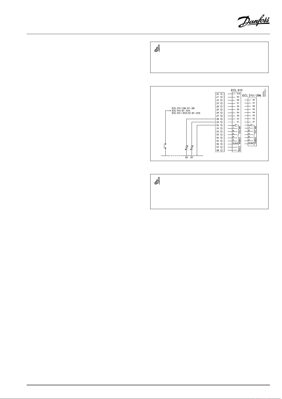
OperatingGuideECLComfort310,applicationA319
Connectionofswitchforexternaloverride
Wirecrosssection:0.5-1.5mm²
Incorrectconnectioncandamagetheelectronicoutputs.
Max.2x1.5mm²wirescanbeinsertedintoeachscrewterminal.
Wirecrosssectionforsensorconnections:Min.0.4mm².
Totalcablelength:Max.200m(allsensorsincl.internalECL485
communicationbus).
Cablelengthsofmorethan200mmaycausenoisesensibility(EMC).
AQ152886470424en-010601
©Danfoss|2021.06|23
Page 24
OperatingGuideECLComfort310,applicationA319
2.5.5Electricalconnections,ECA30/31
Terminal
ECL
Terminal
ECA30/31
30
31
4
1
322
333
4
5
*
Afteranexternalroomtemperaturesensorhasbeenconnected,
Description
Twistedpair
Twistedpair
Ext.roomtemperature
sensor*
Type
(recomm.)
Cable2x
twistedpair
ESM-10
ECA30/31mustberepowered.
ThecommunicationtotheECA30/31mustbesetupintheECL
Comfortcontrollerin'ECAaddr.'
TheECA30/31mustbesetupaccordingly.
AfterapplicationsetuptheECA30/31isreadyafter2–5min.A
progressbarintheECA30/31isdisplayed.
Iftheactualapplicationcontainstwoheatingcircuits,itispossible
toconnectanECA30/31toeachcircuit.Theelectricalconnections
aredoneinparallel.
Max.2ECA30/31canbeconnectedtoanECLComfort310controller
ortoECLComfort210/296/310controllersinamaster-slavesystem.
SetupproceduresforECA30/31:Seesection‘Miscellaneous’ .
ECAinformationmessage:
‘Applicationreq.newerECA’:
Thesoftware(firmware)ofyourECAdoesnotcomplywiththe
software(firmware)ofyourECLComfortcontroller.Pleasecontact
yourDanfosssalesoffice.
Someapplicationsdonotcontainfunctionsrelatedtoactualroom
temperature.TheconnectedECA30/31willonlyfunctionasremote
control.
24|©Danfoss|2021.06
AQ152886470424en-010601
Page 25

OperatingGuideECLComfort310,applicationA319
Totalcablelength:Max.200m(allsensorsincl.internalECL485
communicationbus).
Cablelengthsofmorethan200mmaycausenoisesensibility(EMC).
AQ152886470424en-010601
©Danfoss|2021.06|25
Page 26
OperatingGuideECLComfort310,applicationA319
2.5.6Electricalconnections,master/slavesystems
Thecontrollercanbeusedasmasterorslaveinmaster/slave
systemsviatheinternalECL485communicationbus(2xtwisted
paircable).
TheECL485communicationbusisnotcompatiblewiththeECL
businECLComfort110,200,300and301!
Terminal
Description
Type
(recomm.)
30
Commonterminal
+12V*,ECL485communicationbus
31
*OnlyforECA30/31andmaster/
slavecommunication
32
B,ECL485communicationbus
33
A,ECL485communicationbus
Cable2x
twistedpair
Totalcablelength:Max.200m(allsensorsincl.internalECL485
communicationbus).
Cablelengthsofmorethan200mmaycausenoisesensibility(EMC).
ECL485buscable
MaximumrecommendedlengthoftheECL485busiscalculatedlike
this:
Subtract"TotallengthofallinputcablesofallECLcontrollersinthe
master-slavesystem"from200m.
Simpleexamplefortotallengthofallinputcables,3xECL:
1xECL
3xECL
3xECLReturntemp.sensor:
3xECLRoomtemp.sensor:
Total:
MaximumrecommendedlengthoftheECL485bus:
200-81m=119m
Outdoortemp.sensor:
Flowtemp.sensor:
15m
18m
18m
30m
81m
26|©Danfoss|2021.06
AQ152886470424en-010601
Page 27
OperatingGuideECLComfort310,applicationA319
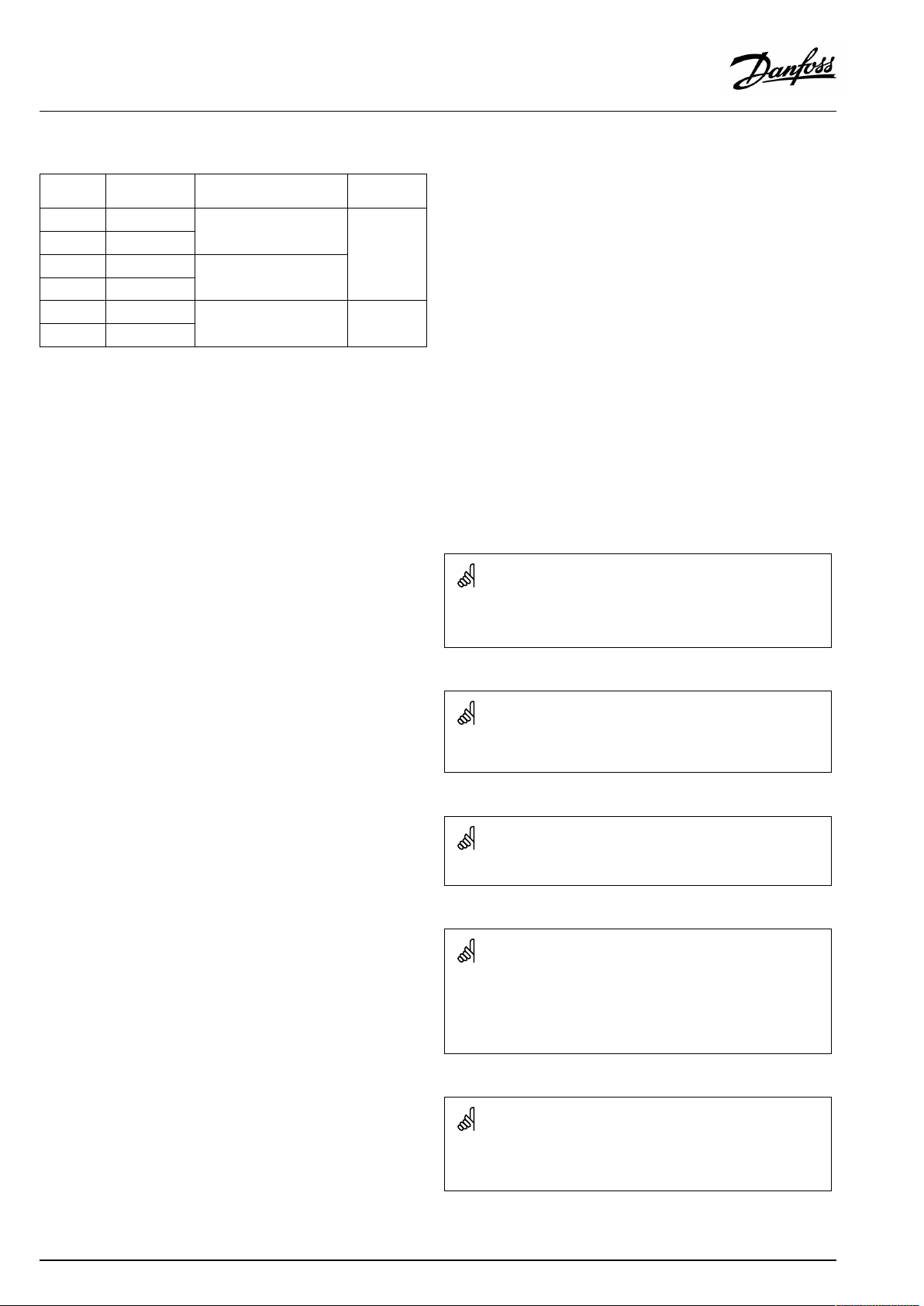
2.5.7Electricalconnections,communication
Electricalconnections,Modbus
ECLComfort210:Non-galvanicisolatedModbusconnections
ECLComfort296:GalvanicisolatedModbusconnections
ECLComfort310:GalvanicisolatedModbusconnections
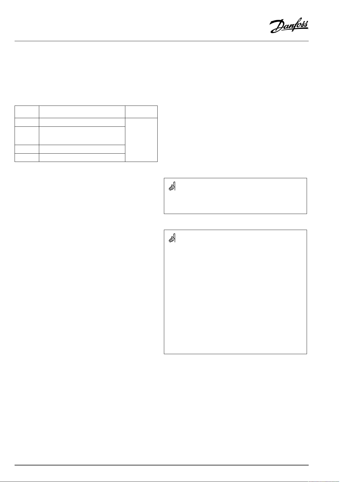
Electricalconnections,M-bus
ECLComfort210:Notimplemented
ECLComfort296:Onboard
ECLComfort310:Onboard
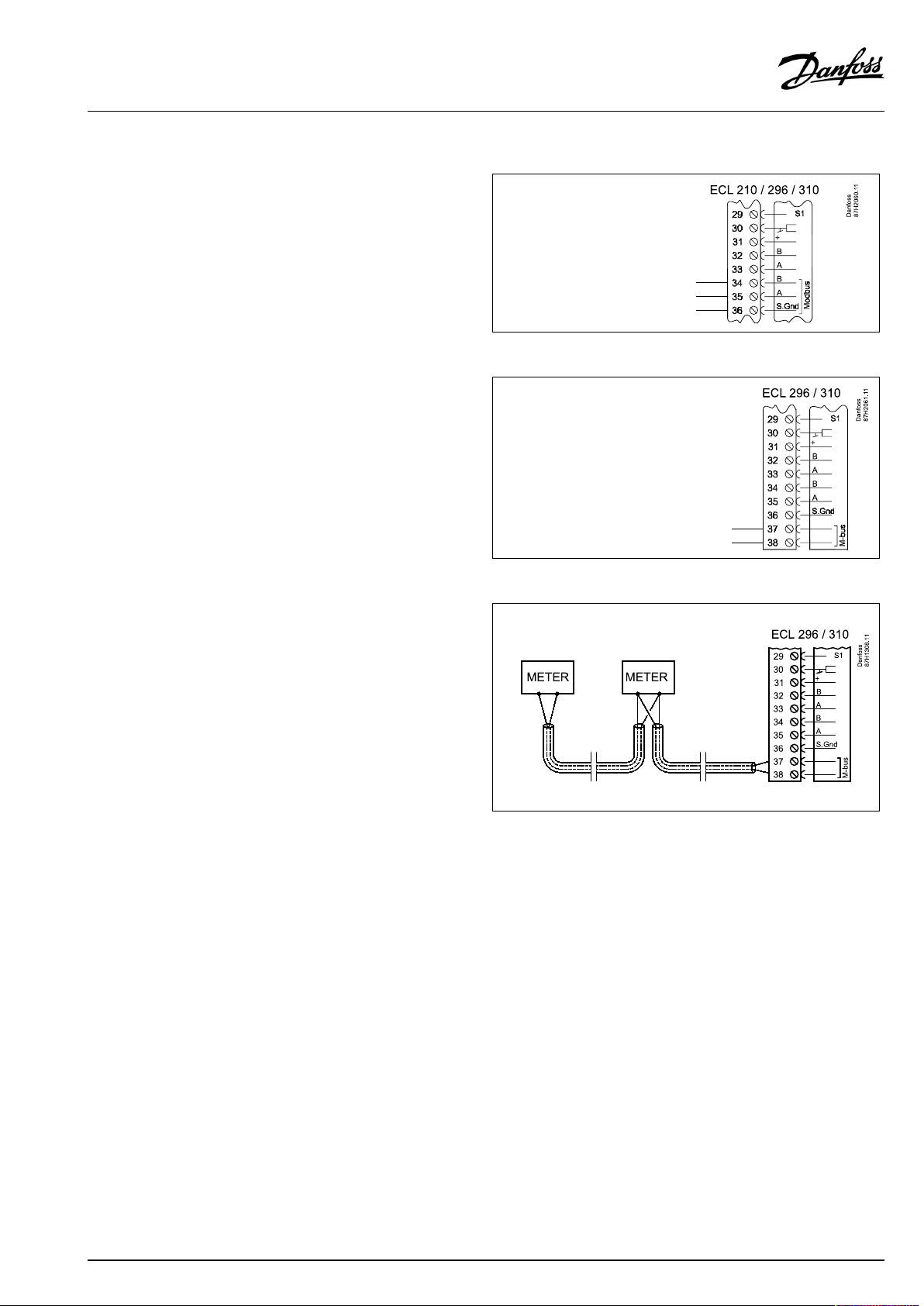
Example,M-busconnections
(ECLComfort296/310and310Bonly)
AQ152886470424en-010601
©Danfoss|2021.06|27
Page 28
OperatingGuideECLComfort310,applicationA319
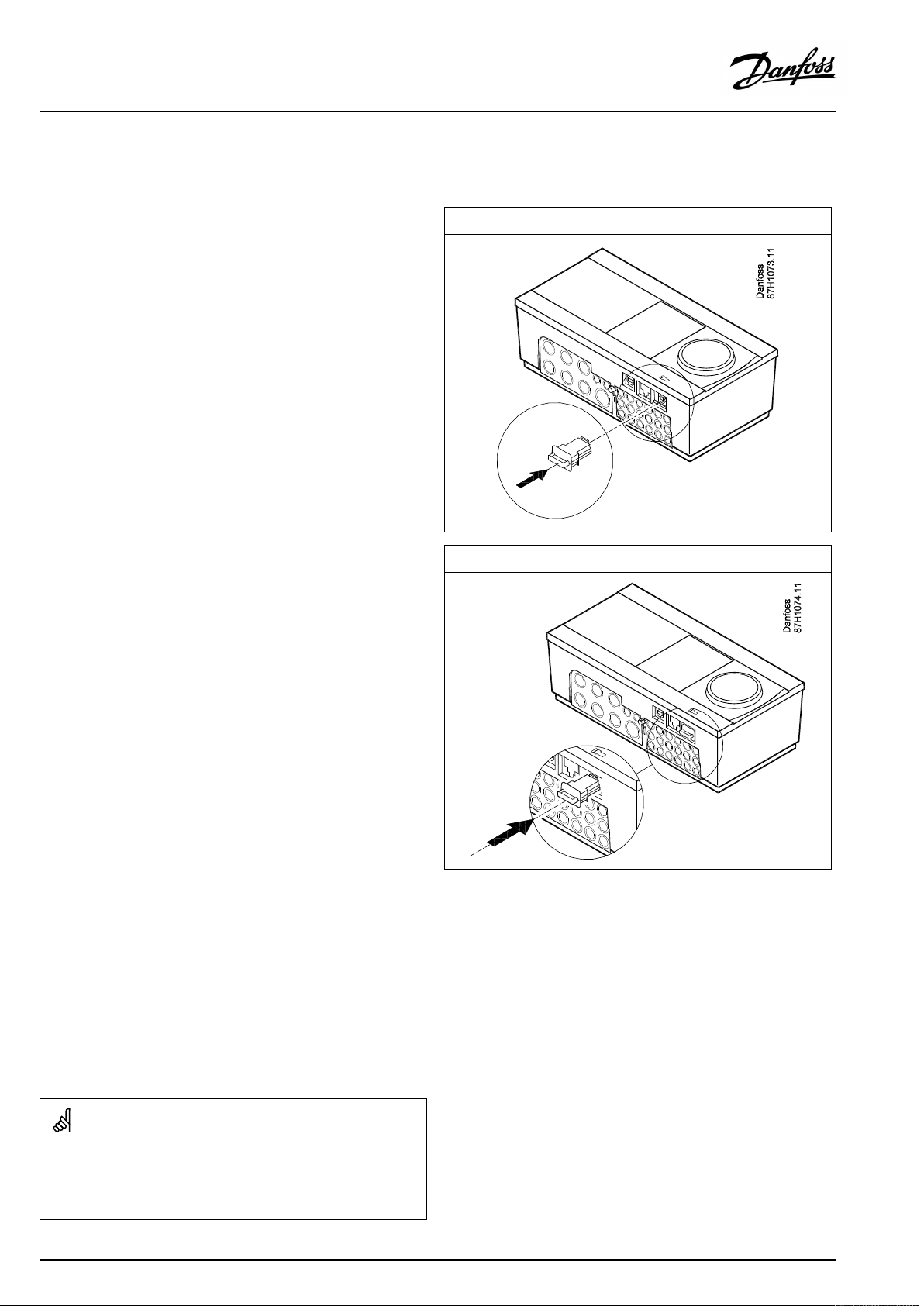
2.6InsertingtheECLApplicationKey
2.6.1InsertingtheECLApplicationKey
TheECLApplicationKeycontains
•theapplicationanditssubtypes,
•currentlyavailablelanguages,
•factorysettings:e.g.schedules,desiredtemperatures,
limitationvaluesetc.Itisalwayspossibletorecoverthefactory
settings,
•memoryforusersettings:specialuser/systemsettings.
Afterhavingpowered-upthecontroller,differentsituationsmight
beexisting:
1.Thecontrollerisnewfromthefactory,theECLApplicationKey
isnotinserted.
2.Thecontrolleralreadyrunsanapplication.TheECLApplication
Keyisinserted,buttheapplicationneedstobechanged.
3.Acopyofthecontrollerssettingsisneededforconfiguring
anothercontroller.
ECLComfort210/310
ECLComfort210/310
Usersettingsare,amongothers,desiredroomtemperature,desired
DHWtemperature,schedules,heatcurve,limitationvaluesetc.
Systemsettingsare,amongothers,communicationset-up,display
brightnessetc.
28|©Danfoss|2021.06
AQ152886470424en-010601
Page 29
OperatingGuideECLComfort310,applicationA319
Automaticupdateofcontrollersoftware(firmware):
Thesoftwareofthecontrollerisupdatedautomaticallywhenthekey
isinserted(asofcontrollerversion1.11(ECL210/310)andversion
1.58(ECL296)).Thefollowinganimationwillbeshownwhenthe
softwareisbeingupdated:
Progressbar
Duringupdate:
•DonotremovetheKEY
Ifthekeyisremovedbeforethehour-glassisshown,youhave
tostartafresh.
•Donotdisconnectthepower
Ifthepowerisinterruptedwhenthehour-glassisshown,the
controllerwillnotwork.
•Manualupdateofcontrollersoftware(firmware):
Seethesection"Automatic/manualupdateoffirmware"
The“Keyoverview”doesnotinform—throughECA30/31—about
thesubtypesoftheapplicationkey.
Keyinserted/notinserted,description:
ECLComfort210/310,controllerversionslowerthan1.36:
-
Takeouttheapplicationkey;for20minutes
settingscanbechanged.
-
Powerupthecontrollerwithoutthe
applicationkeyinserted;for20minutes
settingscanbechanged.
ECLComfort210/310,controllerversions1.36andup:
-
Takeouttheapplicationkey;for20minutes
settingscanbechanged.
-
Powerupthecontrollerwithoutthe
applicationkeyinserted;settingscannotbe
changed.
ECLComfort296,controllerversions1.58andup:
-
Takeouttheapplicationkey;for20minutes
settingscanbechanged.
-
Powerupthecontrollerwithoutthe
applicationkeyinserted;settingscannotbe
changed.
AQ152886470424en-010601
©Danfoss|2021.06|29
Page 30
OperatingGuideECLComfort310,applicationA319
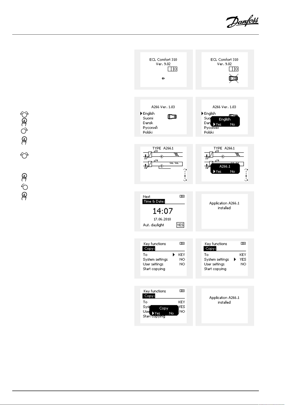
ApplicationKey:Situation1
Thecontrollerisnewfromthefactory,theECLApplicationKey
isnotinserted.
AnanimationfortheECLApplicationKeyinsertionisdisplayed.
InserttheApplicationKey.
ApplicationKeynameandVersionisindicated(example:A266
Ver.1.03).
IftheECLApplicationKeyisnotsuitableforthecontroller,a"cross"
isdisplayedovertheECLApplicationKey-symbol.
Action:Purpose:
Selectlanguage
Confirm
Selectapplication(subtype)
Somekeyshaveonlyoneapplication.
Confirmwith‘Yes’
Set'Time&Date'
Turnandpushthedialtoselectand
change'Hours' ,'Minutes','Date',
'Month'and'Year' .
Choose''Next'
Confirmwith‘Yes’
Goto‘Aut.daylight’
Choosewhether‘ Aut.daylight´*
shouldbeactiveornot
*‘Aut.daylight’istheautomaticchangeoverbetweensummer
andwintertime.
DependingonthecontentsoftheECLApplicationKey,procedure
AorBistakingplace:
A
TheECLApplicationkeycontainsfactorysettings:
Thecontrollerreads/transfersdatafromtheECLApplicationKey
toECLcontroller.
Examples:
YESorNO
Theapplicationisinstalled,andthecontrollerresetsandstartsup.
B
TheECLApplicationkeycontainschangedsystemsettings:
Pushthedialrepeatedly.
’NO’:
’YES*:
Ifthekeycontainsusersettings:
Pushthedialrepeatedly.
‘NO:
‘YES*:
*If‘YES’cannotbechosen,theECLApplicationKeydoesnot
containanyspecialsettings.
Choose‘Startcopying’andconfirmwith'Yes'.
30|©Danfoss|2021.06
OnlyfactorysettingsfromtheECLApplicationKeywill
becopiedtothecontroller.
Specialsystemsettings(differingfromthefactory
settings)willbecopiedtothecontroller.
OnlyfactorysettingsfromtheECLApplicationKeywill
becopiedtothecontroller.
Specialusersettings(differingfromthefactorysettings)
willbecopiedtothecontroller.
AQ152886470424en-010601
Page 31
OperatingGuideECLComfort310,applicationA319
(Example):
The"i"intheupperrightcornerindicatesthat-besidesthefactory
settings-thesubtypealsocontainsspecialuser/systemssettings.
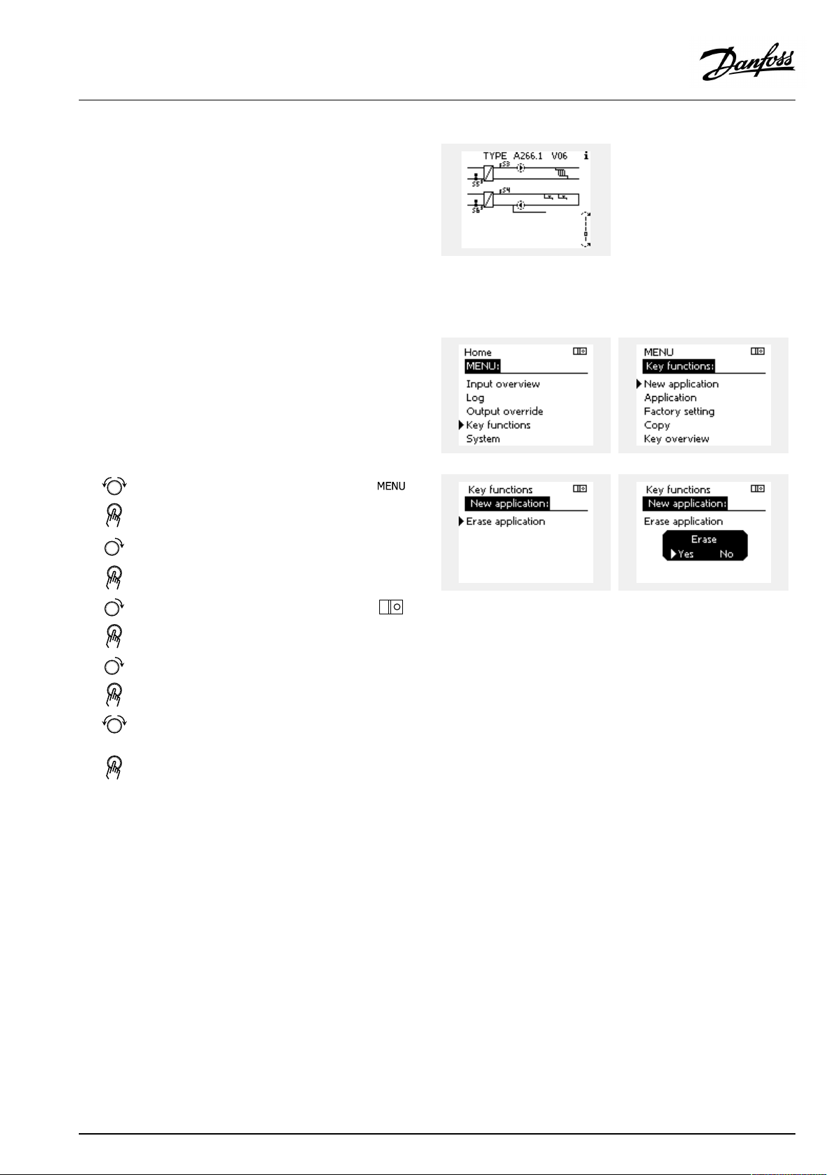
ApplicationKey:Situation2
Thecontrolleralreadyrunsanapplication.TheECLApplication
Keyisinserted,buttheapplicationneedstobechanged.
TochangetoanotherapplicationontheECLApplicationKey,the
currentapplicationinthecontrollermustbeerased(deleted).
BeawarethattheApplicationKeymustbeinserted.
Action:Purpose:
Choose‘MENU’inanycircuit
Confirm
Choosethecircuitselectoratthetop
rightcornerinthedisplay
Confirm
Choose‘Commoncontrollersettings’
Confirm
Choose‘Keyfunctions’
Confirm
Choose‘Eraseapplication’
Confirmwith‘Yes’
Thecontrollerresetsandisreadytobeconfigured.
Followtheproceduredescribedinsituation1.
Examples:
AQ152886470424en-010601
©Danfoss|2021.06|31
Page 32

OperatingGuideECLComfort310,applicationA319
ApplicationKey:Situation3
Acopyofthecontrollerssettingsisneededforconfiguring
anothercontroller.
Thisfunctionisused
•forsaving(backup)ofspecialuserandsystemsettings
•whenanotherECLComfortcontrollerofthesametype(210,
296or310)mustbeconfiguredwiththesameapplicationbut
user/systemsettingsdifferfromthefactorysettings.
HowtocopytoanotherECLComfortcontroller:
Action:Purpose:
Choose‘MENU’
Confirm
Choosethecircuitselectoratthetop
rightcornerinthedisplay
Confirm
Choose'Commoncontrollersettings'
Confirm
Goto‘Keyfunctions’
Confirm
Choose‘Copy’
Confirm
Choose‘To’ .
‘ECL’or‘KEY’willbeindicated.Choose
’ECL’orKEY’
Pushthedialrepeatedlytochoose
copydirection
Choose‘Systemsettings’or‘User
settings’
Pushthedialrepeatedlytochoose
‘Yes’or‘No’in‘Copy’ .Pushtoconfirm.
Choose‘Startcopying’
TheApplicationKeyorthecontroller
isupdatedwithspecialsystemoruser
settings.
Examples:
*
’ECL’or‘KEY’ .
**
‘NO’or‘YES’
*
‘ECL’:
‘KEY’:
**
‘NO’:
‘YES’:
32|©Danfoss|2021.06
DatawillbecopiedfromtheApplicationKeytothe
ECLController.
DatawillbecopiedfromtheECLControllertothe
ApplicationKey.
ThesettingsfromtheECLcontrollerwillnotbecopied
totheApplicationKeyortotheECLComfortcontroller.
Specialsettings(differingfromthefactorysettings)will
becopiedtotheApplicationKeyortotheECLComfort
controller.IfYEScannotbechosen,therearenospecial
settingstobecopied.
AQ152886470424en-010601
Page 33

OperatingGuideECLComfort310,applicationA319
Language
Atapplicationupload,alanguagemustbeselected.*
IfanotherlanguagethanEnglishisselected,theselectedlanguage
ANDEnglishwillbeuploadedintotheECLcontroller.
ThismakesserviceeasyforEnglishspeakingservicepeople,just
becausetheEnglishlanguagemenuscanbevisiblebychanging
theactualsetlanguageintoEnglish.
(Navigation:MENU>Commoncontroller>System>Language)
Iftheuploadedlanguageisnotsuitable,theapplicationmustbe
erased.UserandSystemsettingscanbesavedontheapplication
keybeforeerasing.
Afternewuploadwithpreferredlanguage,theexistingUserand
Systemsettingscanbeuploaded.
*)
(ECLComfort310,24Volt)Iflanguagecannotbeselected,the
powersupplyisnota.c.(alternatingcurrent).
2.6.2ECLApplicationKey,copyingdata
Generalprinciples
Whenthecontrollerisconnectedandoperating,youcancheck
andadjustallorsomeofthebasicsettings.Thenewsettingscan
bestoredontheKey.
Factorysettingscanalwaysberestored.
HowtoupdatetheECLApplicationKeyaftersettingshave
beenchanged?
AllnewsettingscanbestoredontheECLApplicationKey.
Howtostorefactorysettinginthecontrollerfromthe
ApplicationKey?
PleasereadtheparagraphconcerningApplicationKey,Situation
1:Thecontrollerisnewfromthefactory,theECLApplicationKey
isnotinserted.
HowtostorepersonalsettingsfromthecontrollertotheKey?
PleasereadtheparagraphconcerningApplicationKey,Situation3:
Acopyofthecontrollerssettingsisneededforconfiguringanother
controller
Asamainrule,theECLApplicationKeyshouldalwaysremainin
thecontroller.IftheKeyisremoved,itisnotpossibletochange
settings.
Makeanoteofnewsettingsinthe'Settingsoverview'table.
DonotremovetheECLApplicationKeywhilecopying.Thedataon
theECLApplicationKeycanbedamaged!
ItispossibletocopysettingsfromoneECLComfortcontrollerto
anothercontrollerprovidedthatthetwocontrollersarefromthesame
series(210or310).
Furthermore,whentheECLComfortcontrollerhasbeenuploaded
withanapplicationkey,minimumversion2.44,itispossibletoupload
personalsettingsfromapplicationkeys,minimumversion2.14.
AQ152886470424en-010601
©Danfoss|2021.06|33
Page 34

OperatingGuideECLComfort310,applicationA319
The“Keyoverview”doesnotinform—throughECA30/31—about
thesubtypesoftheapplicationkey.
Keyinserted/notinserted,description:
ECLComfort210/310,controllerversionslowerthan1.36:
-
Takeouttheapplicationkey;for20minutes
settingscanbechanged.
-
Powerupthecontrollerwithoutthe
applicationkeyinserted;for20minutes
settingscanbechanged.
ECLComfort210/310,controllerversions1.36andup:
-
Takeouttheapplicationkey;for20minutes
settingscanbechanged.
-
Powerupthecontrollerwithoutthe
applicationkeyinserted;settingscannotbe
changed.
ECLComfort296,controllerversions1.58andup:
-
Takeouttheapplicationkey;for20minutes
settingscanbechanged.
-
Powerupthecontrollerwithoutthe
applicationkeyinserted;settingscannotbe
changed.
34|©Danfoss|2021.06
AQ152886470424en-010601
Page 35

OperatingGuideECLComfort310,applicationA319
2.7Checklist
IstheECLComfortcontrollerreadyforuse?
Makesurethatthecorrectpowersupplyisconnectedtoterminals9and10(230Vor24V).
Makesurethecorrectphaseconditionsareconnected:
230V:Live=terminal9andNeutral=terminal10
24V:SP=terminal9andSN=terminal10
Checkthattherequiredcontrolledcomponents(actuator,pumpetc.)areconnectedtothecorrectterminals.
Checkthatallsensors/signalsareconnectedtothecorrectterminals(see'Electricalconnections').
Mountthecontrollerandswitchonthepower.
IstheECLApplicationKeyinserted(see'InsertingtheApplicationKey').
DoestheECLComfortcontrollercontainanexistingapplication(see'InsertingtheApplicationKey').
Isthecorrectlanguagechosen(see'Language'in'Commoncontrollersettings').
Isthetime&datesetcorrectly(see'Time&Date'in'Commoncontrollersettings').
Istherightapplicationchosen(see'Identifyingthesystemtype').
Checkthatallsettingsinthecontroller(see'Settingsoverview')aresetorthatthefactorysettingscomplywithyour
requirements.
Choosemanualoperation(see'Manualcontrol').Checkthatvalvesopenandclose,andthatrequiredcontrolled
components(pumpetc.)startandstopwhenoperatedmanually.
Checkthatthetemperatures/signalsshowninthedisplaymatchtheactualconnectedcomponents.
Havingcompletedthemanualoperationcheck,choosecontrollermode(scheduled,comfort,savingorfrostprotection).
AQ152886470424en-010601
©Danfoss|2021.06|35
Page 36

OperatingGuideECLComfort310,applicationA319
2.8Navigation,ECLApplicationKeyA319
Navigation,A319.1andA319.2,circuits1and2
Home
MENU
Schedule
Schedule,Circ.pu.
Settings
A319
A319.1A319.2
CircuitCircuit
IDnos.
Weekplan,max.3comfort
periods/day
Factorysettings:
00.00-08.00,08.00-16.00,
16.00-24.00
Weekplan,max.3comfort
periods/day
Factorysettings:
00.00-08.00,08.00-16.00,
16.00-24.00
FlowtemperatureHeatcurve((
11178
11177
11004
Tanktemperature12195Startdifference((
12194
12371
12004
Returnlimit
Controlpar.1
Controlpar.2
12031
12032
12033
12034
12035
12036
12037
12080
12028
1218413184
1218513185
1218613186
1218713187
1218913189
1218414184
1218514185
12186
1218714187
12189
14165
14167
14171
Function
Temp.max.
Temp.min.
Ext.desiredT
DesiredT
Stopdifference
Pumpstartdiff.
DesiredT
HighToutX1
LowlimitY1
LowToutX2
HighlimitY2
Infl.-max.
Infl.-min.
Adapt.time
Delay
Con.T,ret.Tlim.
Xp
Tn
Mrun
Nz
Min.act.time
Xp
Tn
Mrun
Nz
Min.act.time
Voutmax.
Voutmin.
Reverseout
1
((
((
((
((
((
((
2
((
((
((
((
((
((
((
((
((
((
((
((
((
((
((
((
((
(((
(((
(((
((
((
((
1
(
(
2
36|©Danfoss|2021.06
AQ152886470424en-010601
Page 37

OperatingGuideECLComfort310,applicationA319
Navigation,A319.1andA319.2,circuits1and2,continued
Home
MENU
Settings
Holiday
Alarm
Influenceoverview
Des.flowT
A319
A319.1A319.2
CircuitCircuit
IDnos.
Controlpar.3
11558
11184
11185
11187
11165
11167
11171
Application11500SenddesiredT((
11077
11021
1109312093
11141
12141
1114212142
12017
12054
12042
ChargeT
SupplyT
Alarmoverview
Holiday
Ext.override
SCADAoffset
Ext.desiredT
Slave,demand
SCADAoverride
Returnlimit
12147
12148
12149
12150
12340
Function
Pressure,diff.
Pressurediff.des.
Xp
Tn
Nz
Voutmax.
Voutmin.
Reverseout
PfrostT
Totalstop
Frostpr.T
Ext.input
Ext.mode
Demandoffset
Cont.Tcontrol
Char.Ppost-run
Upperdifference
Lowerdifference
Delay
Lowesttemp.
Delay
ChargeT
SupplyT
Tsensordefect
1
((
((
((
((
((
((
((
((
((
((
((((
((((
((((
((
((
((((
((
((((
223
((
((
((
((
((
((
((
((
((
((
((
((
((
((
AQ152886470424en-010601
©Danfoss|2021.06|37
Page 38

OperatingGuideECLComfort310,applicationA319
Navigation,A319,Commoncontrollersettings
Home
MENU
Time&Date
ScheduleSelectable
Inputoverview
Log
Outputoverride
Keyfunctions
OutdoorTLogtoday
FlowT&desiredLogyesterday
Pressure,diff.&des.
ChargeT&des.Log4days
ReturnT&limit
SupplyT
TankTup&des.
TankTup&low.
NewapplicationEraseapplication
Application
FactorysettingSystemsettings
Copy
Keyoverview
IDno.
Commoncontrollersettings
Function
Selectable
OutdoorT
FlowT
ChargeT
SupplyT
Prim.returnT
TankupperT
TanklowerT
Pressure,diff.
Ext.desiredT
Log2days
M1
V2
P2
M2(A319.2only)
V3
P3
X1
A1
Usersettings
Gotofactory
To
Systemsettings
Usersettings
Startcopying
38|©Danfoss|2021.06
AQ152886470424en-010601
Page 39
OperatingGuideECLComfort310,applicationA319
Navigation,A319,Commoncontrollersettings,continued
Home
MENU
SystemECLversion
Extension
Ethernet(ECLComfort310only)
Portalconfig(ECLComfort310only)
M-busconfig(ECLComfort310only)
EnergyMeters
(ECLComfort310only)
Rawinputoverview
Alarm
Display
Communication
Language
IDno.
Commoncontrollersettings
Function
Codeno.
Hardware
Software
Serialno.
Productiondate
Addresstype
ECLportal
Portalstatus
Portalinfo
5998
Command
5997
Baud
6000
M-busaddress
6002
Scantime
6001
Type
EnergyMeter1....5
S1-S10(S1-S18whenECA32/35isinstalled)
32:
Tsensordefect
60058
Backlight
60059
Contrast
2048
ECL485addr.
38
Modbusaddr.
39
Baud
2150
Servicepin
2151
Ext.reset
2050
Language
AQ152886470424en-010601
©Danfoss|2021.06|39
Page 40

OperatingGuideECLComfort310,applicationA319
3.0Dailyuse
3.1Howtonavigate
Younavigateinthecontrollerbyturningthedialleftorrightto
thedesiredposition().
Thedialhasabuilt-inaccellerator.Thefasteryouturnthedial,the
fasteritreachesthelimitsofanywidesettingrange.
Thepositionindicatorinthedisplay(
youare.
Pushthedialtoconfirmyourchoices().
Thedisplayexamplesarefromatwo-circuitapplication:One
heatingcircuit()andonedomestichot-water(DHW)circuit().
Theexamplesmightdifferfromyourapplication.
)willalwaysshowyouwhere
ExampleshowsECL210/310
Heatingcircuit():DHWcircuit();
Somegeneralsettingswhichapplytotheentirecontrollerare
locatedinaspecificpartofthecontroller.
Toenter‘Commoncontrollersettings’:
Action:Purpose:
Choose‘MENU’inanycircuit
Confirm
Choosethecircuitselectoratthetop
rightcornerinthedisplay
Confirm
Choose‘Commoncontrollersettings’
Confirm
Examples:
Circuitselector
40|©Danfoss|2021.06
AQ152886470424en-010601
Page 41
OperatingGuideECLComfort310,applicationA319
3.2Understandingthecontrollerdisplay
ThissectiondescribesthefunctioningeneralfortheECLComfort
210/296/310series.Theshowndisplaysaretypicalandnot
applicationrelated.Theymightdifferfromthedisplaysinyour
application.
Choosingafavoritedisplay
Yourfavoritedisplayisthedisplayyouhavechosenasthedefault
display.Thefavoritedisplaywillgiveyouaquickoverviewofthe
temperaturesorunitsthatyouwanttomonitoringeneral.
Ifthedialhasnotbeenactivatedfor20min.,thecontrollerwill
reverttotheoverviewdisplayyouhavechosenasfavorite.
Toshiftbetweendisplays:Turnthedialuntilyoureachthedisplay
selector(
turntochooseyourfavoriteoverviewdisplay.Pushthedialagain.
)atthebottomrightsideofthedisplay.Pushthedialand
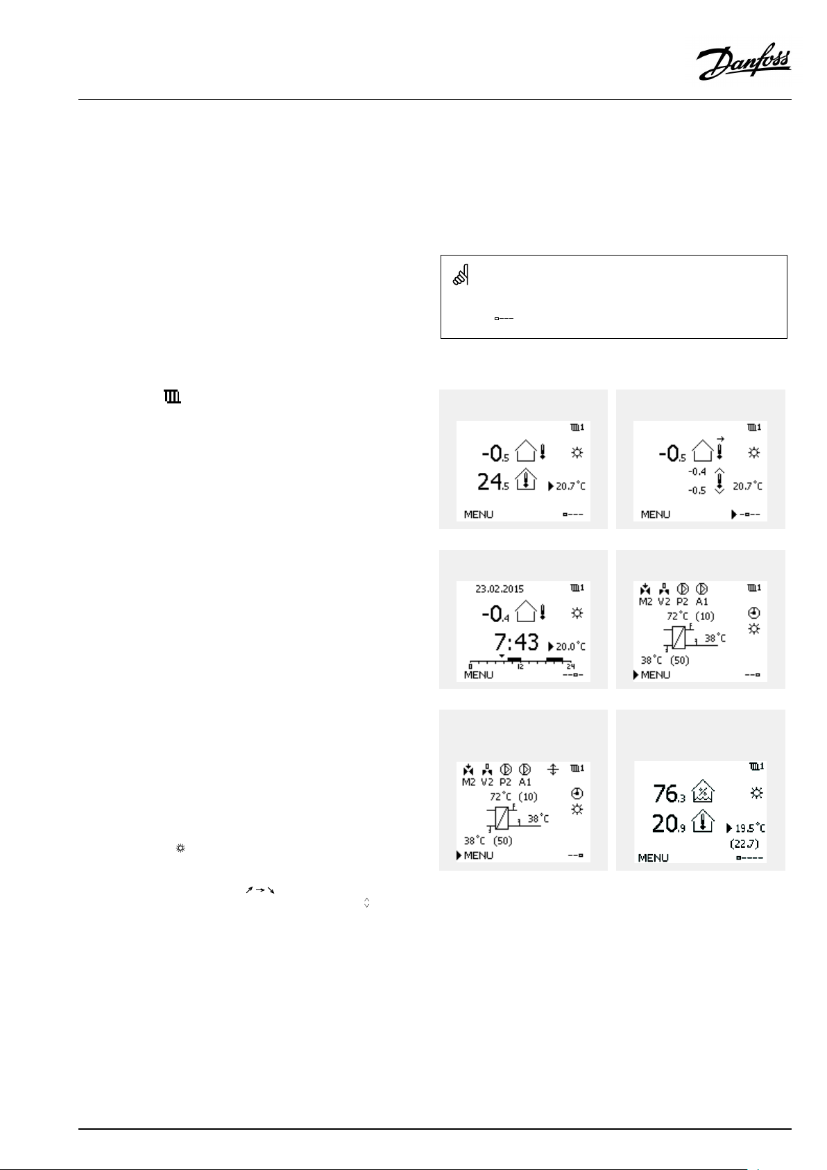
Heatingcircuit
Overviewdisplay1informsabout:
actualoutdoortemperature,controllermode,
actualroomtemperature,desiredroomtemperature.
Overviewdisplay2informsabout:
actualoutdoortemperature,trendinoutdoortemperature,
controllermode,max.andmin.outdoortemperaturessince
midnightaswellasdesiredroomtemperature.
Overviewdisplay3informsabout:
date,actualoutdoortemperature,controllermode,time,desired
roomtemperatureaswellasshowsthecomfortscheduleofthe
currentday.
Overviewdisplay4informsabout:
stateofthecontrolledcomponents,actualflowtemperature,
(desiredflowtemperature),controllermode,returntemperature
(limitationvalue),influenceondesiredflowtemperature.
ThevalueabovetheV2symbolindicates0–100%oftheanalogue
signal(0–10V).
Note:
Anactualflowtemperaturevaluemustbepresent,otherwisethe
circuit'scontrolvalvewillclose.
Overviewdisplay1:Overviewdisplay2:
Overviewdisplay3:Overviewdisplay4:
Exampleofoverviewdisplaywith
Influenceindication:
Example,favoritedisplay1in
A230.3,wheremin.desiredroom
temperatureisindicated(22.7):
Dependentonthechosendisplay,theoverviewdisplaysforthe
heatingcircuitinformyouabout:
•actualoutdoortemperature(-0.5)
•controllermode()
•actualroomtemperature(24.5)
•desiredroomtemperature(20.7°C)
•trendinoutdoortemperature(
)
•min.andmax.outdoortemperaturessincemidnight(
•date(23.02.2010)
•time(7:43)
•comfortscheduleofthecurrentday(0-12-24)
•stateofthecontrolledcomponents(M2,P2)
•actualflowtemperature(49°C),(desiredflowtemperature(31))
•returntemperature(24°C)(limitationtemperature(50))
AQ152886470424en-010601
)
©Danfoss|2021.06|41
Page 42

OperatingGuideECLComfort310,applicationA319
Settingthedesiredtemperature
Dependingonthechosencircuitandmode,itispossibletoenter
alldailysettingsdirectlyfromtheoverviewdisplays(seealsothe
nextpageconcerningsymbols).
Thesettingofthedesiredroomtemperatureisimportantevenifa
roomtemperaturesensor/RemoteControlUnitisnotconnected.
Ifthetemperaturevalueisdisplayedas
"--"
thesensorinquestionisnotconnected.
"---"
thesensorconnectionisshort-circuited.
Settingthedesiredroomtemperature
Thedesiredroomtemperaturecaneasilybeadjustedinthe
overviewdisplaysfortheheatingcircuit.
Action:Purpose:
Examples:
Desiredroomtemperature
Confirm
Adjustthedesiredroomtemperature
Confirm
Thisoverviewdisplayinformsaboutoutdoortemperature,actual
roomtemperatureaswellasdesiredroomtemperature.
Thedisplayexampleisforcomfortmode.Ifyouwanttochange
thedesiredroomtemperatureforsavingmode,choosethemode
selectorandselectsaving.
20.5
21.0
42|©Danfoss|2021.06
Thesettingofthedesiredroomtemperatureisimportantevenifa
roomtemperaturesensor/RemoteControlUnitisnotconnected.
AQ152886470424en-010601
Page 43

OperatingGuideECLComfort310,applicationA319
Settingthedesiredroomtemperature,ECA30/ECA31
Thedesiredroomtemperaturecanbesetexactlyasinthe
controller.However,othersymbolscanbepresentinthedisplay
(pleasesee'Whatdothesymbolsmean?').
WiththeECA30/ECA31youcanoverridethedesiredroom
temperaturesetinthecontrollertemporarilybymeansoftheoverride
functions:
AQ152886470424en-010601
©Danfoss|2021.06|43
Page 44

OperatingGuideECLComfort310,applicationA319
3.3Ageneraloverview:Whatdothesymbolsmean?
Symbol
Description
Outdoortemp.
Relativehumidityindoor
Roomtemp.
DHWtemp.
Positionindicator
Scheduledmode
Comfortmode
Savingmode
Frostprotectionmode
Manualmode
Standby
Coolingmode
Symbol
Temperature
Mode
Description
Alarm
Letter
Event
Monitoringtemperaturesensor
connection
Displayselector
Max.andmin.value
Trendinoutdoortemperature
Windspeedsensor
Sensornotconnectedornotused
Sensorconnectionshort-circuited
Fixedcomfortday(holiday)
Activeinfluence
Heatingactive(+)
Coolingactive(-)
Activeoutputoverride
Optimizedstartorstoptime
Heating
Cooling
DHW
Commoncontrollersettings
PumpON
PumpOFF
FanON
FanOFF
Actuatoropens
Actuatorcloses
Actuator,analoguecontrol
signal
Pump/fanspeed
DamperON
Circuit
Controlled
component
Numberofheatexchangers
Additionalsymbols,ECA30/31:
Symbol
InECA30/31onlythesymbolsthatarerelevanttotheapplicationin
thecontrolleraredisplayed.
Description
ECARemoteControlUnit
Connectionaddress(master:15,slaves:1-9)
15
Dayoff
Holiday
Relaxing(extendedcomfortperiod)
Goingout(extendedsavingperiod)
44|©Danfoss|2021.06
DamperOFF
AQ152886470424en-010601
Page 45

OperatingGuideECLComfort310,applicationA319
3.4Monitoringtemperaturesandsystemcomponents
ThissectiondescribesthefunctioningeneralfortheECLComfort
210/296/310series.Theshowndisplaysaretypicalandnot
applicationrelated.Theymightdifferfromthedisplaysinyour
application.
Heatingcircuit
Theoverviewdisplayintheheatingcircuitensuresaquick
overviewoftheactualand(desired)temperaturesaswellasthe
actualstateofthesystemcomponents.
Displayexample:
49°C
(31)
24°C
(50)
Inputoverview
Anotheroptiontogetaquickoverviewofmeasuredtemperatures
isthe'Inputoverview'whichisvisibleinthecommoncontroller
settings(howtoenterthecommoncontrollersettings,see
‘Introductiontocommoncontrollersettings’ .)
Asthisoverview(seedisplayexample)onlystatesthemeasured
actualtemperatures,itisread-only.
Flowtemperature
Desiredflowtemperature
Returntemperature
Returntemperaturelimitation
AQ152886470424en-010601
©Danfoss|2021.06|45
Page 46

OperatingGuideECLComfort310,applicationA319
3.5Influenceoverview
ThissectiondescribesthefunctioningeneralfortheECLComfort
210/296/310series.Theshowndisplaysaretypicalandnot
applicationrelated.Theymightdifferfromthedisplaysinyour
application.
Themenugivesanoverviewoftheinfluencesonthedesired
flowtemperature.Itdiffersfromapplicationtoapplicationwhich
parametersarelisted.Itcanbehelpfulinaservicesituationto
explainunexpectedconditionsortemperaturesamongothers.
Ifthedesiredflowtemperatureisinfluenced(corrected)byoneor
moreparameters,itisindicatedbyasmalllinewitharrow-down,
arrow-upordouble-arrow:
Arrow-down:
Theparameterinquestionreducesthedesiredflowtemperature.
Arrow-up:
Theparameterinquestionincreasesthedesiredflowtemperature.
Double-arrow:
Theparameterinquestioncreatesanoverride(e.g.Holiday).
Straightline:
Noactiveinfluence.
Intheexample,thearrowinthesymbolpointsdownwardsfor
'Roomlim. ' .Thismeansthattheactualroomtemperatureis
higherthanthedesiredroomtemperaturewhichagainresultsina
decreaseofthedesiredflowtemperature.
ExampleofoverviewdisplaywithInfluenceindication:
46|©Danfoss|2021.06
AQ152886470424en-010601
Page 47

OperatingGuideECLComfort310,applicationA319
3.6Manualcontrol
ThissectiondescribesthefunctioningeneralfortheECLComfort
210/296/310series.Theshowndisplaysaretypicalandnot
applicationrelated.Theymightdifferfromthedisplaysinyour
application.
Itispossibletomanuallycontroltheinstalledcomponents.
Manualcontrolcanonlybeselectedinfavoritedisplaysinwhich
thesymbolsforthecontrolledcomponents(valve,pumpetc.)are
visible.
Action:Purpose:
Choosemodeselector
Confirm
Choosemanualmode
Confirm
Choosepump
Confirm
SwitchONthepump
SwitchOFFthepump.
Confirmpumpmode
Choosemotorizedcontrolvalve
Confirm
Openthevalve
Stopopeningthevalve
Closethevalve
Examples:
ControlledcomponentsCircuitselector
Duringmanualoperation:
•Allcontrolfunctionsaredeactivated
•Outputoverrideisnotpossible
•Frostprotectionisnotactive
Stopclosingthevalve
Confirmvalvemode
Toleavemanualcontrol,usethemodeselectortoselectthe
desiredmode.Pushthedial.
Manualcontrolistypicallyusedwhencommisioningthe
installation.Thecontrolledcomponents,valve,pumpetc.,canbe
controlledforcorrectfunction.
AQ152886470424en-010601
Whenmanualcontrolisselectedforonecircuit,itisautomatically
selectedforallcircuits!
Manualcontrolof0–10Volt/PWMcontrolledpumpspeed:
TheV1andV2symbolshaveavalue(in%)whichcanbechanged.
The%valueiscorrespondingtoavoltage/PWMintherange0–10
Volt/0-100%PWM.
©Danfoss|2021.06|47
Page 48

OperatingGuideECLComfort310,applicationA319
3.7Schedule
3.7.1Setyourschedule
ThissectiondescribesthescheduleingeneralfortheECLComfort
210/296/310series.Theshowndisplaysaretypicalandnot
applicationrelated.Theymightdifferfromthedisplaysinyour
application.Insomeapplications,however,theremightbemore
thanoneschedule.Additionalschedulescanbefoundin‘Common
controllersettings’ .
Thescheduleconsistsofa7-dayweek:
=
M
Monday
=
T
Tuesday
=
W
Wednesday
=
T
Thursday
=
F
Friday
=
S
Saturday
=
S
Sunday
Theschedulewillday-by-dayshowyouthestartandstoptimesof
yourcomfortperiods(heating/DHWcircuits).
Changingyourschedule:
Action:
Purpose:
Choose'MENU'inanyoftheoverview
displays
Confirm
Confirmthechoice'Schedule'
Choosethedaytochange
Confirm*
GotoStart1
Confirm
Adjustthetime
Confirm
GotoStop1,Start2etc.etc.
Returnto'MENU'
Confirm
Choose'Yes'or'No'in'Save'
Confirm
Examples:
*Severaldayscanbemarked
Thechosenstartandstoptimeswillbevalidforallthechosendays
(inthisexampleThursdayandSaturday).
Youcansetmax.3comfortperiodsaday.Youcandeleteacomfort
periodbysettingstartandstoptimestothesamevalue.
48|©Danfoss|2021.06
Eachcircuithasitsownschedule.Tochangetoanothercircuit,goto
'Home',turnthedialandchoosethedesiredcircuit.
Thestartandstoptimescanbesetinhalf-hourly(30min.)intervals.
AQ152886470424en-010601
Page 49

OperatingGuideECLComfort310,applicationA319
4.0Settingsoverview
Forfactorysettingsandsettingrange,seeappendix“ParameterIDoverview” .
ParametersindicatedwithanIDno.like"1x607"meanauniversalparameter.xstandsforcircuit/parametergroup.
SettingIDPage
Heatcurve
Ext.desiredT—(ECLComfort310)
Pressure,diff.
DesiredT(Desiredflowtemperature)
DesiredT(Desiredflowtemperature)
Demandoffset
Totalstop
Con.T,re.Tlim.(Constanttemperaturemode,return
temperaturelimitation)
HighToutX1(returntemp.limitation,highlimit,X-axis)
LowlimitY1(returntemp.limitation,lowlimit,Y-axis)
LowToutX2(returntemp.limitation,lowlimit,X-axis)
HighlimitY2(returntemp.limitation,highlimit,Y-axis)
Infl.-max.(returntemp.limitation-max.influence)
Infl.-min.(returntemp.limitation-min.influence)
Adapt.time(adaptationtime)
Char.Ppost-run(Chargingpump,post-run)
Cont.Tcontrol(Continuedtemperaturecontrol)
PfrostT(circulationpump,frostprotectiontemp.)
Delay
Frostpr.T(frostprotectiontemp.)
Ext.input(externaloverride)
Ext.mode(externaloverridemode)
Upperdifference
Lowerdifference
Delay,example
Lowesttemp.
Voutmax.
Voutmin.
Reverseout
Temp.min.
Temp.max.
Xp(proportionalband)
Tn(integrationtimeconstant)
Mrun(runningtimeofthemotorizedcontrolvalve)
Nz(neutralzone)
Min.act.time(min.activationtimegearmotor)
Stopdifference
Startdifference
1x00453
1x00472
1x01765
1x02165
1x02856
1x03156
1x032
1x033
1x034
1x035
1x036
1x03758
1x04266
1x05466
1x07767
1x08058
1x09367
1x141
1x14268
1x14775
1x14876
1x14976
1x150
1x16561
1x16761
1x171
1x17754
1x178
1x18462
1x18562
1x18662
1x18763
1x18963
1x19472
1x19573
Factorysettingsincircuit(s)
1
52
52
60
57
57
57
57
57
67
77
61
54
2
AQ152886470424en-010601
©Danfoss|2021.06|49
Page 50

OperatingGuideECLComfort310,applicationA319
SettingIDPage
Delay
Pumpstartdiff.
SenddesiredT
Pressurediff.des.(Pressuredifference,desired)
1x340
1x371
1x50070
1x55863
Factorysettingsincircuit(s)
1
77
74
2
50|©Danfoss|2021.06
AQ152886470424en-010601
Page 51

OperatingGuideECLComfort310,applicationA319
5.0Settings
5.1IntroductiontoSettings
Descriptionsofsettings(parameter'sfunctions)aredividedinto
groupsasusedintheECLComfort210/296/310controller's
menustructure.Examples:"Flowtemperature" ,"Roomlimit"and
soon.Eachgroupstartswithageneralexplanation.
Thedescriptionsofeachparameterareinnumericorder,relatedto
theparameter'sIDnumbers.Youmightcomeacrossdifferences
betweentheorderinthisOperatingGuideandtheECLComfort
210/296/310controllers.
Someparameterdescriptionsarerelatedtospecificapplication
subtypes.Thismeansthatyoumightnotseetherelatedparameter
intheactualsubtypeintheECLcontroller.
Thenote"SeeAppendix… "referstotheAppendixattheendof
thisOperatingGuide,whereparameter'ssettingrangesandfactory
settingsarelisted.
Thenavigationhints(forexampleMENU>Settings>Returnlimit
…)covermultiplesubtypes.
AQ152886470424en-010601
©Danfoss|2021.06|51
Page 52

OperatingGuideECLComfort310,applicationA319
5.2Flowtemperature
TheECLComfortcontrollerdeterminesandcontrolstheflow
temperaturerelatedtotheoutdoortemperature.Thisrelationship
iscalledtheheatcurve.
Theheatcurveissetbymeansof6coordinatepoints.Thedesired
flowtemperatureissetat6pre-definedoutdoortemperature
values.
Theshownvaluefortheheatcurveisanaveragevalue(slope),
basedontheactualsettings.
Slopechanges
Outdoortemp.
(factorysettings)Yoursettings
-30°C75°C
-15°C70°C
-5°C65°C
0°C60°C
5°C60°C
15°C60°C
MENU>Settings>Flowtemperature
Desiredtemperature:
Heatcurve
CircuitSettingrange
1
0.1...4.01.0
Theheatcurvecanbechangedintwoways:
1.Thevalueoftheslopeischanged(seeheatcurveexamples
onnextpage)
2.Thecoordinatesoftheheatcurvearechanged
Example:
Heatcurve:
Desiredflowtemp.:
Desiredroomtemp.:
Calculation(22–20)×1.0×2.5=
Result:
Thedesiredflowtemperaturewillbecorrectedfrom50°Cto55°C.
Factorysetting
1.0
50°C
22°C
5
Changethevalueoftheslope:
Pushthedialtoenter/changetheslopevalueoftheheatcurve
(example:1.0).
Whentheslopeoftheheatcurveischangedbymeansoftheslope
value,thecommonpointforallheatcurveswillbeadesiredflow
temperature=24.6°Catanoutdoortemperature=20°C
Changethecoordinates:
Pushthedialtoenter/changethecoordinatesoftheheatcurve
(example:-30,75).
Theheatcurverepresentsthedesiredflowtemperaturesat
differentoutdoortemperaturesandatadesiredroomtemperature
of20°C.
Ifthedesiredroomtemperatureischanged,thedesiredflow
temperaturealsochanges:
(DesiredroomT-20)×HC×2.5
where"HC"istheHeatCurveslopeand"2.5"isaconstant.
52|©Danfoss|2021.06
AQ152886470424en-010601
Page 53

OperatingGuideECLComfort310,applicationA319
Externalsignalfordesiredflowtemperature
Avoltage(0-10V)canbeappliedtotheinputterminalS10in
ordertodeterminethedesiredflowtemperature.
ThemeasuredvoltageoninputS10mustbeconvertedtoa
temperaturevaluebythecontroller.Whenthevoltagegetshigher,
thedesiredflowtemperatureincreases.
Thefollowingsettingssetupthescaling.
MENU>Settings>Flowtemperature
Ext.desiredT—(ECLComfort310)
CircuitSettingrange
1
Theactualdesiredflowtemperatureisindicatedbytheunit°C.
Read-outonly
Factorysetting
Read-out:
--:
°C:
Externalvoltagesignalisnotconnected..
Externalvoltagesignalconvertedtodesiredflow
temperature.
Pushthedialtoseethegraphandenterthevaluesetsfortheinput
voltage(1and10volt)anddisplayeddesiredflowtemperature.
Example:Relationshipbetweeninputvoltageanddisplayeddesiredflow
temperature
Desiredflowtemp.(°C)
Volt
Thisexampleshowsthat1voltcorrespondsto10.0°Cand10volt
correspondto100°C.
Desiredflowtemperature:
10...120°C
Fixedvoltagesettings:1Vand10V
Factorysettings:
(1,10)and(10,100)
Thismeansthatthe‘Desiredflowtemperature’is10°Cat1.0V
and100°Cat10V.
Typically,thehigherthevoltage,thehigherthedisplayeddesired
flowtemperature.
ParametersindicatedwithanIDno.like"1x607"meanauniversal
parameter.
xstandsforcircuit/parametergroup.
Theexternalvoltagesignalmustbehigherthan1.0Vinorderto
activatetheoverride.
AQ152886470424en-010601
©Danfoss|2021.06|53
Page 54

OperatingGuideECLComfort310,applicationA319
MENU>Settings>Flowtemperature
DesiredT(Desiredflowtemperature)
WhentheECLComfortisinoverridemode,type"Const.T",thedesiredflow
temperaturecanbeset.
A"Const.T"relatedreturntemperaturelimitationcanalsobeset.SeeMENU
>Settings>Returnlimit>'Con.T,ret.Tlim. '
1x004
SeeAppendix“ParameterIDoverview”
MENU>Settings>Flowtemperature
Temp.min.
1x177
SeeAppendix“ParameterIDoverview”
Setthemin.flowtemperatureforthesystem.Thedesiredflow
temperaturewillnotbelowerthanthissetting.Adjustthefactory
setting,ifrequired.
Overridemode
WhenECLComfortisinScheduledmode,acontact(switch)signalcan
beappliedtoaninputinordertooverridetoComfort,Saving,Frost
ProtectionorConstanttemperature.Aslongasthecontact(switch)
signalisapplied,theoverrideisactive.
The"DesiredT"valuecanbeinfluencedby:
•temp.max.
•temp.min.
•roomtemp.limit
•returntemp.limit
•flow/powerlimit
‘Temp.min.’isoverruledif'Totalstop'isactiveinSavingmodeor
'Cut-out'isactive.
‘Temp.min.’canbeoverruledbytheinfluencefromthereturn
temperaturelimitation(see'Priority').
MENU>Settings>Flowtemperature
Temp.max.
1x178
SeeAppendix“ParameterIDoverview”
Setthemax.flowtemperatureforthesystem.Thedesired
temperaturewillnotbehigherthanthissetting.Adjustthefactory
setting,ifrequired.
Thesettingfor‘Temp.max. ’hashigherprioritythan‘Temp.min.’ .
Thesettingof‘heatcurve’ispossibleforheatingcircuitsonly.
Thesettingfor‘Temp.max. ’hashigherprioritythan‘Temp.min.’ .
54|©Danfoss|2021.06
AQ152886470424en-010601
Page 55

OperatingGuideECLComfort310,applicationA319
5.3Returnlimit
Thereturntemperaturelimitationisbasedontheoutdoor
temperature.Typicallyindistrictheatingsystemsahigherreturn
temperatureisacceptedatadecreaseinoutdoortemperature.The
relationshipbetweenthereturntemperaturelimitsandoutdoor
temperatureissetintwocoordinates.
Theoutdoortemperaturecoordinatesaresetin'HighToutX1'
and'LowToutX2' .Thereturntemperaturecoordinatesaresetin
'HighlimitY2'and'LowlimitY1' .
Thecontrollerautomaticallychangesthedesiredflowtemperature
toobtainanacceptablereturntemperaturewhenthereturn
temperaturefallsbeloworgetshigherthanthecalculatedlimit.
ThislimitationisbasedonaPIregulationwhereP('Infl.'factor)
respondsquicklytodeviationsandI('Adapt.time')responds
slowerandovertimeremovesthesmalloffsetsbetweenthe
desiredandactualvalues.Thisisdonebychangingthedesired
flowtemperature.
X
Y
#X1#
#X2#
#Y1#
#Y2#
=
Outdoortemperature
=
Limitationtemperature
=
HighTout(1x031)
=
LowTout(1x033)
=
Lowlimit(1x032)
=
Highlimit(1x034)
Example,maximumreturntemperaturelimitation;
returntemperaturegetshigherthanlimit
Thecalculatedlimitisshowninbrackets()inthemonitoringdisplay.
Seethesection"Monitoringtemperaturesandsystemcomponents" .
=
T
Temperature
=
Y
Temperature
=
X
Time
=
#1#
Returntemperature
=
#2#
Returntemperaturelimit
=
#3#
Desiredflowtemperature
=
#4#
Actionpoint
AQ152886470424en-010601
©Danfoss|2021.06|55
Page 56

OperatingGuideECLComfort310,applicationA319
Example,minimumreturntemperaturelimitation;
returntemperaturegetslowerthanlimit
=
T
Y
X
#1#
#2#
#3#
#4#
Temperature
=
Temperature
=
Time
=
Returntemperature
=
Returntemperaturelimit
=
Desiredflowtemperature
=
Actionpoint
ParametersindicatedwithanIDno.like"1x607"meanauniversal
parameter.
xstandsforcircuit/parametergroup.
MENU>Settings>Returnlimit
Con.T,re.Tlim.(Constanttemperaturemode,return
temperaturelimitation)
The"Con.T ,ret.Tlimit"isthereturntemperaturelimitationvaluewhenthe
circuitissettooverridemodetype"Const.T"(=Constanttemperature).
SeeAppendix“ParameterIDoverview”
Value:Setthereturntemperaturelimitation
1x028
56|©Danfoss|2021.06
AQ152886470424en-010601
Page 57

OperatingGuideECLComfort310,applicationA319
MENU>Settings>Returnlimit
HighToutX1(returntemp.limitation,highlimit,X-axis)
Settheoutdoortemperaturevalueforthelowreturntemperaturelimitation.
SeeAppendix“ParameterIDoverview”
ThecorrespondingYcoordinateissetin'LowlimitY1' .
MENU>Settings>Returnlimit
LowlimitY1(returntemp.limitation,lowlimit,Y-axis)
Setthereturntemperaturelimitationreferringtotheoutdoortemperature
valuesetin'HighToutX1' .
SeeAppendix“ParameterIDoverview”
ThecorrespondingXcoordinateissetin'HighToutX1' .
MENU>Settings>Returnlimit
LowToutX2(returntemp.limitation,lowlimit,X-axis)
Settheoutdoortemperaturevalueforthehighreturntemperature
limitation.
1x031
1x032
1x033
SeeAppendix“ParameterIDoverview”
ThecorrespondingYcoordinateissetin'HighlimitY2'.
MENU>Settings>Returnlimit
HighlimitY2(returntemp.limitation,highlimit,Y-axis)
Setthereturntemperaturelimitationreferringtotheoutdoortemperature
valuesetin'LowToutX2' .
SeeAppendix“ParameterIDoverview”
ThecorrespondingXcoordinateissetin'LowToutX2' .
MENU>Settings>Returnlimit
Infl.-max.(returntemp.limitation-max.influence)
Determineshowmuchthedesiredflowtemperaturewillbeinfluencedifthe
returntemperatureishigherthanthesetlimit.
SeeAppendix“ParameterIDoverview”
Influencehigherthan0:
Thedesiredflowtemperatureisincreased,whenthereturn
temperaturegetshigherthanthesetlimit.
1x034
Example
1x035
Thereturnlimitisactiveabove50°C.
Theinfluenceissetto0.5.
Theactualreturntemperatureis2degreestoohigh.
Result:
Thedesiredflowtemperatureischangedby0.5x2=1.0degree.
Influencelowerthan0:
Thedesiredflowtemperatureisdecreased,whenthereturn
temperaturegetshigherthanthesetlimit.
AQ152886470424en-010601
©Danfoss|2021.06|57
Page 58

OperatingGuideECLComfort310,applicationA319
MENU>Settings>Returnlimit
Infl.-min.(returntemp.limitation-min.influence)
Determineshowmuchthedesiredflowtemperaturewillbeinfluencedifthe
returntemperatureislowerthanthecalculatedlimit.
SeeAppendix“ParameterIDoverview”
Influencehigherthan0:
Thedesiredflowtemperatureisincreased,whenthereturn
temperaturegetsbelowthecalculatedlimit.
Influencelowerthan0:
Thedesiredflowtemperatureisdecreased,whenthereturn
temperaturegetsbelowthecalculatedlimit.
MENU>Settings>Returnlimit
Adapt.time(adaptationtime)
Controlshowfastthereturntemperatureadaptstothedesiredreturn
temperaturelimit(Integrationcontrol).
SeeAppendix“ParameterIDoverview”
OFF:
Thecontrolfunctionisnotinfluencedbythe‘Adapt.
time’ .
Minor
Thedesiredtemperatureisadaptedquickly.
value:
Major
Thedesiredtemperatureisadaptedslowly.
value:
Example
1x036
1x037
Thereturnlimitisactivebelow50°C.
Theinfluenceissetto-3.0.
Theactualreturntemperatureis2degreestoolow.
Result:
Thedesiredflowtemperatureischangedby-3.0x2=-6.0degrees.
Normally,thissettingis0indistrictheatingsystemsbecausealower
returntemperatureisacceptable.
Typically,thissettingishigherthan0inboilersystemstoavoidatoo
lowreturntemperature(seealso'Infl.-max.').
Theadaptationfunctioncancorrectthedesiredflowtemperature
withmax.8K.
MENU>Settings>Returnlimit
Delay
WhenthechargingpumphasbeenswitchedON,thecontrollerawaitsthe
set'Delay'beforeactivatingthereturntemperaturelimitation.
SeeAppendix“ParameterIDoverview”
1x080
58|©Danfoss|2021.06
AQ152886470424en-010601
Page 59

OperatingGuideECLComfort310,applicationA319
5.4Controlparameters
Controlofvalves
Themotorizedcontrolvalvesarecontrolledbymeansof3-point
controlsignal.
Valvecontrol:
Themotorizedcontrolvalveisopenedgraduallywhentheflow
temperatureislowerthanthedesiredflowtemperatureandvice
versa.
Thewaterflowthroughthecontrolvalveismanagedbymeans
ofanelectricactuator.Thecombination"actuator"and"control
valve"isalsocalledmotorizedcontrolvalve.Theactuatorcanin
thiswaygraduallyincreaseordecreasetheflowinordertochange
thesuppliedenergy.Differenttypesofactuatorsareavailable.
3-pointcontrolledactuator:
Theelectricactuatorcontainsareversiblegear-motor.Electric
"open"and"close"signalscomefromtheelectronicoutputsofthe
ECLComfortcontrollerinordertomanagethecontrolvalve.The
signalsareintheECLComfortcontrollerexpressedas"Arrow-up"
(open)and"Arrow-down"(close)anddisplayedatthevalvesymbol.
Whentheflowtemperature(forexampleatS3)islowerthanthe
desiredflowtemperature,shortopen-signalscomefromtheECL
Comfortcontrollerinordertograduallyincreasetheflow.Bythis,
theflowtemperaturewillalignwiththedesiredtemperature.
Oppositely,whentheflowtemperatureishigherthanthedesired
flowtemperature,shortclose-signalscomefromtheECLComfort
controllerinordertograduallyreducetheflow.Again,theflow
temperaturealignswiththedesiredtemperature.
Neitheropen-signalsnorclose-signalswillcomeaslongastheflow
temperaturecorrespondstothedesiredtemperature.
Speedcontrolofcirculationpump
ThecirculationpumpP3canbespeedcontrolledbymeansofa010voltsignaloraPWM(PulseWidthModulation)signal.Thespeed
controlsignal,as0-10V,comesfromthe"AnalogOut3"(terminals
61and56)ontheECA32or35module.
Thespeedcontrolsignal,asPWM,comesfromtheoutput"PWM
Out3"(terminals54and49)ontheECA35module.
AdesiredpressuredifferenceatS9issetforthespeedcontrol
procedure.
Thecontrolvoltage/PWMisexpressedasa%valueanddisplayed
attheV3symbol.
Whenthepressuredifferencegetslowerthanthedesiredpressure
difference,thecontrolvoltageisgraduallyincreasedinorderto
increasethespeedofthecirculationpumpmorethanthemoment
before.Bythis,thepressuredifferencealignswiththedesired
pressuredifference.
Thecontrolvoltage/PWMremainsonastablevalueaslongasthe
pressuredifferencecorrespondstothedesiredpressuredifference.
Thecontrolvoltage/PWMcanbelimitedtoamaximumanda
minimum%value.
Furthermore,thecontrolsignalcanbereversed;thismeansthe
higherthe%value,thelowerthespeed.
AQ152886470424en-010601
©Danfoss|2021.06|59
Page 60

OperatingGuideECLComfort310,applicationA319
Speedcontrolofchargingpump
ThechargingpumpP2canbespeedcontrolledbymeansofa010voltsignaloraPWM(PulseWidthModulation)signal.Thespeed
controlsignal,as0-10V,comesfromthe"AnalogOut2"(terminals
60and56)ontheECA32or35module.
Thespeedcontrolsignal,asPWM,comesfromtheoutput"PWM
Out2"(terminals53and49)ontheECA35module.
WhenthechargingtemperatureatS3islessthan2Kbelow
thedesiredchargingtemperature,thespeedwillbeincreased
gradually.
Thecontrolvoltage/PWMisexpressedasa%valueanddisplayed
attheV2symbol.
Whenthedifferencebetweenchargingtemperatureanddesired
chargingtemperaturebecomesmorethan2K,thespeedwillbe
decreasedgradually.
Thecontrolvoltage/PWMcanbelimitedtoamaximumanda
minimum%value.
Furthermore,thecontrolsignalcanbereversed;thismeansthe
higherthe%value,thelowerthespeed.
Thecontrolparametersareusedfordifferentissues,forexample
temperatureandpumpspeedcontrol.
ParametersXp(proportionalband)withID11184and14184are
specificallyusedforpumpspeedcontrol.
ParametersTn(integrationtimeconstant)withID11185and14185
arespecificallyusedforpumpspeedcontrol.
ParametersNz(neutralzone)withID11187and14187are
specificallyusedforpumpspeedcontrol.
ParametersVoutmax.andVoutmin.(ID1x165and1x167)are
settingthelimitsforthecontrolvoltageaswellasforthePWM
control.
ParametersindicatedwithanIDno.like"1x607"meanauniversal
parameter.
xstandsforcircuit/parametergroup.
60|©Danfoss|2021.06
AQ152886470424en-010601
Page 61

OperatingGuideECLComfort310,applicationA319
MENU>Settings>Controlparameters
Pressure,diff.
CircuitSettingrange
Read-out2.0Volt=0.0bar
PressuredifferencemeasuredatS9.Voltagefrompressuredifference
transmitterisconvertedtoapressuredifferencevalueinbar.
Settingofscaleat2.0Voltand10.0Volt.
Thepressuredifferenceismeasuredbymeansofa0-10voltsignal.
Themeasuredvoltagemustbeconvertedtoapressuredifference
valuebythecontroller.
Thefollowingproceduresetsuptheconversion:
Pushthedialtoseethegraphandenterthevaluesetsforthe2
inputvoltagesandrelatedpressuredifferencevalues.
Pressuredifferencevaluerange:0.0-20.0bar.
Thefactorysetvoltagevalues(2.0voltand10.0volt)cannotbe
changed.
Factorysettings:2,0(=2V/0.0bar)and10,10.0(=10V/10.0bar).
Thismeansthatthe"Pressuredifference"is0.0barat2Vand10.0
barat10V.
Typically,thehigherthevoltage,thehigherthedisplayedpressure
difference.
Factorysetting
10.0Volt=10.0bar
MENU>Settings>Controlparameters
Voutmax.
Theoutputvoltagecanbelimitedtoamaximumvalue.
SeeAppendix“ParameterIDoverview”
Thevaluein%expressesthemaximumvoltagefortheoutputin
question.
MENU>Settings>Controlparameters
Voutmin.
Theoutputvoltagecanbelimitedtoaminimumvalue.
SeeAppendix“ParameterIDoverview”
Thevaluein%expressestheminimumvoltagefortheoutputin
question.
1x165
Example
Asettingof60%meansthattheoutputvoltagewillbe6voltasa
maximum.
1x167
Example:
Asettingof20%meansthattheoutputvoltagewillbe2voltasa
minimum.
Thesetting'Reverseout'hasnoinfluenceonthe'Voutmax’or‘V
outmin'settings.
The'Voutmin'settinghashigherprioritythan'Voutmax' .
AQ152886470424en-010601
©Danfoss|2021.06|61
Page 62

OperatingGuideECLComfort310,applicationA319
MENU>Settings>Controlparameters
Reverseout
ValidonlywhentheinternalI/OmoduleECA35isused:
Theanalogoutput(0-10volt)canbearisingorafallingvoltageforrising
pressuredifferencedemand.AlsothePWMsignalcanbereversed.
SeeAppendix“ParameterIDoverview”
OFF:
Theanalogoutputvoltagewillriseatarisingpressure
differencedemand.
ThePWMsignalwillrisein%atarisingpressure
differencedemand.
ON:
Theanalogoutputvoltagewillfallatarisingpressure
differencedemand.
ThePWMsignalwillfallin%atarisingpressure
differencedemand.
MENU>Settings>Controlparameters
Xp(proportionalband)
SeeAppendix“ParameterIDoverview”
Settheproportionalband.Ahighervaluewillresultinastablebut
slowcontroloftheflowtemperature.
1x171
1x184
Specialfortheparameters11184/14184:
Settheproportionalbandforthespeedcontrol.Ahighervaluewill
resultinastable,butslowcontrolofthespeed.
MENU>Settings>Controlparameters
Tn(integrationtimeconstant)
SeeAppendix“ParameterIDoverview”
Setahighintegrationtimeconstant(inseconds)toobtainaslow
butstablereactiontodeviations.
Alowintegrationtimeconstantwillmakethecontrollerreactfast
butwithlessstability.
Specialfor11185/14185:
Settheintegrationtimeforthespeedcontrol.Setahighervalue
(inseconds)toobtainaslow,butstablereactiontodeviations.
Alowintegrationtimeconstantwillmakethecontrollerreactfast,
butwithlessstability.
1x185
62|©Danfoss|2021.06
AQ152886470424en-010601
Page 63

OperatingGuideECLComfort310,applicationA319
MENU>Settings>Controlparameters
Mrun(runningtimeofthemotorizedcontrolvalve)
‘Mrun’isthetimeinsecondsittakesthecontrolledcomponenttomove
fromfullyclosedtofullyopenposition.
SeeAppendix“ParameterIDoverview”
Setthe‘Mrun’accordingtotheexamplesormeasuretherunning
timebymeansofastopwatch.
MENU>Settings>Controlparameters
1x186
Howtocalculatetherunningtimeofamotorizedcontrolvalve
Therunningtimeofthemotorizedcontrolvalveiscalculatedusing
thefollowingmethods:
Seatedvalves
Runningtime=
Example:
Rotatingvalves
Runningtime=
Example:90degr.x2sec./degr.=180sec.
Valvestroke(mm)xactuatorspeed(sec./mm)
5.0mmx15sec./mm=75sec.
Turningdegreesxactuatorspeed(sec./degr.)
Nz(neutralzone)
Whentheactualflowtemperatureiswithintheneutralzone,thecontroller
doesnotactivatethemotorizedcontrolvalve.
SeeAppendix“ParameterIDoverview”
Settheacceptableflowtemperaturedeviation.
Settheneutralzonetoahighvalueifyoucanacceptahigh
variationinflowtemperature.
Specialfor11187/14187:
Settheacceptablepressuredifferencedeviation/temperature
deviation.
Whentheactualpressuredifference/temperatureiswithinthe
neutralzone,thecontrollerdoesnotchangethepumpspeed.
MENU>Settings>Controlparameters
Min.act.time(min.activationtimegearmotor)
Themin.pulseperiodof20ms(milliseconds)foractivationofthegear
motor.
SeeAppendix“ParameterIDoverview”
1x187
Theneutralzoneissymmetricalaroundthedesiredflowtemperature
value,i.e.halfthevalueisaboveandhalfthevalueisbelowthis
temperature.
SettingexampleValuex20ms
1x189
240ms
10200ms
501000ms
MENU>Settings>Controlparameters
Pressurediff.des.(Pressuredifference,desired)
Settingthedesiredpressuredifference.
SeeAppendix“ParameterIDoverview”
AQ152886470424en-010601
Thesettingshouldbekeptashighasacceptabletoincreasethe
lifetimeoftheactuator(gearmotor).
1x558
©Danfoss|2021.06|63
Page 64

OperatingGuideECLComfort310,applicationA319
IfyouwanttotunethePIregulationprecisely,youcanusethefollowingmethod:
•Setthe‘Tn’(integrationtimeconstant)toitsmax.value(999sec.).
•Decreasethevalueforthe‘Xp’(proportionalband)untilthesystemstartshunting(i.e.getsunstable)withaconstantamplitude(it
mightbenecessarytoforcethesystembysettinganextremelowvalue).
•Findthecriticaltimeperiodonthetemperaturerecorderoruseastopwatch.
Temp.
Thiscriticaltimeperiodwillbecharacteristicforthesystem,andyoucanevaluatethesettingsfromthiscriticalperiod.
‘Tn’=
0.85xcriticaltimeperiod
‘Xp’=
2.2xproportionalbandvalueinthecriticaltimeperiod
Iftheregulationseemstobetooslow,youcandecreasetheproportionalbandvalueby10%.Makesurethereisaconsumption
whenyousettheparameters.
Criticaltimeperiod
Time
64|©Danfoss|2021.06
AQ152886470424en-010601
Page 65

OperatingGuideECLComfort310,applicationA319
5.5Application
Thesection"Application"describesspecificapplicationrelated
issues.
Someoftheparameterdescriptionsareuniversalfordifferent
applicationkeys.
ParametersindicatedwithanIDno.like"1x607"meanauniversal
parameter.
xstandsforcircuit/parametergroup.
MENU>Settings>Application
Demandoffset
Thedesiredflowtemperatureincircuit2canbeinfluencedbythedemand
foradesiredflowtemperaturefromanothercircuitoranothercontroller
(slave).
SeeAppendix“ParameterIDoverview”
OFF:
Thedesiredflowtemperatureisnotinfluencedbythe
demandofanyothercircuitorcontroller(slave).
1...20:
Thedesiredflowtemperatureisincreasedbytheset
valuein‘Demandoffset’ ,ifthedemandofanothercircuit
orcontroller(slave)ishigher.
1x017
Thefunctionof‘Demandoffset’cancompensateforheatlosses
betweenmasterandslavecontrolledsystems.
AQ152886470424en-010601
©Danfoss|2021.06|65
Page 66

OperatingGuideECLComfort310,applicationA319
MENU>Settings>Application
Totalstop
Decidewhetheryouwantatotalstopduringthesavingtemperatureperiod.
1x021
SeeAppendix“ParameterIDoverview”
OFF:
Nototalstop.Thedesiredflowtemperatureisreduced
accordingto:
•desiredroomtemperatureinsavingmode
•autosaving
ON:
Thedesiredflowtemperatureisloweredtothesetvalue
in‘Frostpr. ’Thecirculationpumpisstoppedbutfrost
protectionisstillactive,see'PfrostT' .
Totalstop=OFF
Totalstop=ON
X
Y
=
Time
=
Desiredflowtemperature
=
Comforttemperature
=
Savingtemperature
=
Frostprotection
MENU>Settings>Application
Char.Ppost-run(Chargingpump,post-run)
Setthechargingpumppost-runtime(minutes).
ThechargingpumpcancontinuetobeswitchedONafterthebufferheating
procedureinordertoutilizetheremainingheatintheheatexchanger.
SeeAppendix“ParameterIDoverview”
0...30:
Setthenumberofminutesforthepost-run.
Themin.flowtemperaturelimitation('Temp.min.')isoverruledwhen
'Totalstop'isON.
1x042
The'Chargingpump,post-run'isnotrespectedifcharging
temperatureS3islowerthandesiredchargingtemperature.
66|©Danfoss|2021.06
AQ152886470424en-010601
Page 67

OperatingGuideECLComfort310,applicationA319
MENU>Settings>Application
Cont.Tcontrol(Continuedtemperaturecontrol)
ThedesiredheatingtemperatureatS4canbemaintainedafterthebuffer
heatingprocedurehaselapsed.
SeeAppendix“ParameterIDoverview”
OFF:
ThedesiredtemperatureatS4isnotmaintained.The
controlvalvecloses.
ON:
ThedesiredtemperatureatS4ismaintained.
MENU>Settings>Application
PfrostT(circulationpump,frostprotectiontemp.)
Frostprotection,basedontheoutdoortemperature.
Whentheoutdoortemperaturegetsbelowthesettemperaturevaluein‘P
frostT’ ,thecontrollerautomaticallyswitchesONthecirculationpump(for
exampleP1orX3)toprotectthesystem.
SeeAppendix“ParameterIDoverview”
OFF:
Value:
Nofrostprotection.
CirculationpumpisONwhentheoutdoortemperature
isbelowthesetvalue.
1x054
1x077
Undernormalconditions,yoursystemisnotfrostprotectedifyour
settingisbelow0°CorOFF.
Forwater-basedsystems,asettingof2°Cisrecommended.
Iftheoutdoortemperaturesensorisnotconnectedandthefactory
settinghasnotbeenchangedto'OFF' ,thecirculationpumpisalways
ON.
MENU>Settings>Application
Frostpr .T(frostprotectiontemp.)
SetthedesiredflowtemperatureattemperaturesensorS3toprotectthe
systemagainstfrost(atheatingcut-out,totalstopetc.).
WhenthetemperatureatS3getslowerthanthesetting,themotorized
controlvalveopensgradually.
SeeAppendix“ParameterIDoverview”
1x093
Thefrostprotectiontemperaturecanalsobesetinyourfavorite
displaywhenthemodeselectorisinfrostprotectionmode.
AQ152886470424en-010601
©Danfoss|2021.06|67
Page 68

OperatingGuideECLComfort310,applicationA319
Overridemodefunctions:
ThefollowingsettingsdescribethefunctioningeneralfortheECL
Comfort210/296/310series.Theexplainedmodesaretypical
andnotapplicationrelated.Theymightdifferfromtheoverride
modesinyourapplication.
MENU>Settings>Application
Ext.input(externaloverride)
Choosetheinputfor'Ext.input'(externaloverride).Bymeansofaswitch
thecontrollercanbeoverriddento‘Comfort’,'Saving' ,'Frostprotection'or
'Constanttemperature'mode.
1x141
SeeAppendix“ParameterIDoverview”
OFF:
S1...S16:
Noinputshavebeenselectedforexternaloverride.
Inputselectedforexternaloverride.
IfS1...S6ischosenasoverrideinput,theoverrideswitchmusthave
gold-platedcontacts.
IfS7...S16ischosenasoverrideinput,theoverrideswitchcanbea
standardcontact.
Seethedrawingsforconnectionexamplesofoverrideswitchand
overriderelaytoinputS8.
S7...S16arerecommendedforoverrideswitch.
Example:Connectionofanoverrideswitch
Example:Connectionofanoverriderelay
IfECA32ismounted,alsoS11...S16canbeused.
IfECA35ismounted,alsoS11orS12canbeused.
Chooseonlyanunusedinputforoverride.Ifanalreadyusedinputis
appliedforoverride,thefunctionalityofthisinputisalsoneglected.
Seealso‘Ext.mode’.
68|©Danfoss|2021.06
AQ152886470424en-010601
Page 69

OperatingGuideECLComfort310,applicationA319
MENU>Settings>Application
Ext.mode(externaloverridemode)
ThemodeoverridecanbeactivatedforSaving,Comfort,Frostpr.or
ConstantTmode.
Foroverride,thecontrollermodemustbeinscheduledmode.
SeeAppendix“ParameterIDoverview”
Chooseanoverridemode:
SAVING:
Thecircuitinquestionisinsavingmodewhenthe
overrideswitchisclosed.
COMFORT:
Thecircuitinquestionisincomfortmodewhenthe
overrideswitchisclosed.
FROSTPR.:
TheheatingorDHWcircuitcloses,butisstillfrost
protected.
CONSTANTT:
Thecircuitinquestioncontrolsaconstant
temperature*)
*)
Seealso'DesiredT'(1x004),settingofdesiredflow
temperature(MENU>Settings>Flowtemperature)
Seealso'Con.T,ret.Tlim. '(1x028),settingofreturn
temperaturelimitation(MENU>Settings>Return
limit)
Theprocessdiagramsshowthefunctionality.
1x142
Seealso‘Ext.input’.
Example:OverridetoComfortmode
#1#=Overrideswitch(notactivated/activated)
#2#=Functionmode(Schedule/Comfort)
#3#=Time
Example:OverridetoSavingmode
#1#=Overrideswitch(notactivated/activated)
#2#=Functionmode(Schedule/Saving)
#3#=Time
Theresultofoverrideto'Saving'modedependsonthesettingin
'Totalstop'.
Totalstop=OFF:Heatingreduced
Totalstop=ON:Heatingstopped
AQ152886470424en-010601
©Danfoss|2021.06|69
Page 70

OperatingGuideECLComfort310,applicationA319
Example:OverridetoFrostprotectionmode
#1#=Overrideswitch(notactivated/activated)
#2#=Functionmode(Schedule/Frostpr.)
#3#=Time
Example:OverridetoConstanttemperaturemode
#1#=Overrideswitch(notactivated/activated)
#2#=Functionmode(Schedule/Const.T)
#3#=Time
The"Const.T"valuecanbeinfluencedby:
•temp.max.
•temp.min.
•roomtemp.limit
•returntemp.limit
•flow/powerlimit
70|©Danfoss|2021.06
AQ152886470424en-010601
Page 71

OperatingGuideECLComfort310,applicationA319
MENU>Settings>Application
SenddesiredT
Whenthecontrolleractsasaslavecontrollerinamaster/slavesystem,
informationaboutthedesiredflowtemperaturecanbesenttothemaster
controllerviatheECL485bus.
Stand-alonecontroller:
Sub-circuitscansendthedesiredflowtemperaturetothemastercircuit.
SeeAppendix“ParameterIDoverview”
OFF:
Informationaboutthedesiredflowtemperatureisnot
senttothemastercontroller.
ON:
Informationaboutthedesiredflowtemperatureissent
tothemastercontroller.
1x500
Inthemastercontroller,'Demandoffset'mustbesettoavalueinorder
toreactonadesiredflowtemperaturefromaslavecontroller.
Whenthecontrolleractsasaslave,itsaddressmustbe1,2,3...9in
ordertosendthedesiredtemperaturetothemaster(seethesection
‘Miscellaneous’ ,‘Severalcontrollersinthesamesystem’).
AQ152886470424en-010601
©Danfoss|2021.06|71
Page 72

OperatingGuideECLComfort310,applicationA319
5.6Tanktemperature
Pleasenote:
ThebuffertanktemperaturesensorsS6andS8mustbeconnected.
ParametersindicatedwithanIDno.like"1x607"meanauniversal
parameter.
xstandsforcircuit/parametergroup.
MENU>Settings>Tanktemperature
DesiredT(Desiredflowtemperature)
WhentheECLComfortisinoverridemode,type"Const.T",thedesiredflow
temperaturecanbeset.
A"Const.T"relatedreturntemperaturelimitationcanalsobeset.SeeMENU
>Settings>Returnlimit>'Con.T,ret.Tlim. '
SeeAppendix“ParameterIDoverview”
1x004
Overridemode
WhenECLComfortisinScheduledmode,acontact(switch)signalcan
beappliedtoaninputinordertooverridetoComfort,Saving,Frost
ProtectionorConstanttemperature.Aslongasthecontact(switch)
signalisapplied,theoverrideisactive.
The"DesiredT"valuecanbeinfluencedby:
•temp.max.
•temp.min.
•roomtemp.limit
•returntemp.limit
•flow/powerlimit
72|©Danfoss|2021.06
AQ152886470424en-010601
Page 73

OperatingGuideECLComfort310,applicationA319
MENU>Settings>Tanktemperature
Stopdifference
Setthenumberofdegreesbelowthedesiredbuffertanktemperature,which
willstopthebuffertankcharging.
Thechargingstopprocessisrelatedtothelowerbuffertanktemperature
sensor.
SeeAppendix“ParameterIDoverview”
–50...–1:
Setthenumberofdegrees.
Examplewith‘Stopdifference’value:
1x194
=
X
Time
=
T
Temperature
=
#1#
Desiredbuffertanktemperature
=
#2#
'Stopdifference'
=
#3#
Lowerbuffertanktemperature
=
#4#
Buffertankcharging
Exampleshowingstopconditions:
=
X
Time
=
T
Temperature
=
#1#
Desiredbuffertanktemperature
=
#2#
‘Startdifference'
=
#3#
Upperbuffertanktemperature
=
#4#
'Stopdifference'
=
#5#
Lowerbuffertanktemperature
=
#6#
Buffertankcharging
AQ152886470424en-010601
©Danfoss|2021.06|73
Page 74

OperatingGuideECLComfort310,applicationA319
MENU>Settings>Tanktemperature
Startdifference
Setthenumberofdegreesbelowthedesiredbuffertanktemperature,which
willstartthebuffertankcharging.
Thechargingstartprocessisrelatedtotheupperbuffertanktemperature
sensor.
SeeAppendix“ParameterIDoverview”
-50...–1:
Setthenumberofdegrees.
Example:
1x195
Desiredbuffertanktemp.:
Startdifference:
Result:
Thebuffertankchargingstartswhenthetemperaturemeasuredby
theupperbuffertanktemperaturesensorgetslowerthan57°C.
60°C
-3K
Examplewith‘Startdifference’value:
=
X
T
#1#
#2#
#3#
#4#
Time
=
Temperature
=
Desiredbuffertanktemperature
=
'Startdifference'
=
Upperbuffertanktemperature
=
Buffertankcharging
MENU>Settings>Tanktemperature
Pumpstartdiff.
ChargingpumpP2isswitchedONwhensupplytemperatureS2getshigher
than('Desiredbuffertemperature'+'Pumpstartdiff. ').
Example:60°C+3K=63°C
SeeAppendix“ParameterIDoverview”
1x371
74|©Danfoss|2021.06
AQ152886470424en-010601
Page 75

OperatingGuideECLComfort310,applicationA319
5.7Alarm
Thesection"Alarm"describesspecificapplicationrelatedissues.
ApplicationA319offersdifferenttypesofalarms:
1.Actualchargingtemperaturediffersfromthedesiredcharging
temperature
2.Supplytemperatureistoolow
3.Disconnectionorshort-circuitingofatemperaturesensoror
itsconnection
ThealarmfunctionsactivateA1(relay6)andthealarmbell-symbol.
Thealarmrelaycanactivatealamp,ahorn,aninputtoanalarm
transmittingdeviceetc.
Thealarmsymbol/relayisactivated:
•aslongasthealarmreasonispresent(automaticreset).
Alarmtype1:
Ifthechargingtemperaturedeviatesmorethanthesetdifferences
fromthedesiredchargingtemperature,thealarmsymbol/relay
willbeactivated.
Ifthechargingtemperaturebecomesacceptable,thealarmsymbol
/relaywillbede-activated.
Alarmtype2:
Ifthesupplytemperaturedoesnotgetabove(desiredcharging
temp.+thesetting'Pumpstartdiff.'(ID12371)),thealarmsymbol
/relaywillbeactivated.
Thereisadelay('SupplyT,-Delay')whichmustelapsebeforethe
alarmisactivated.
NOTE:Toresetthealarm:Set'SupplyT,-Delay'to0minutes.
Alarmtype3:
Selectedtemperaturesensorscanbemonitored.
Shouldtheconnectiontothetemperaturesensorbedisconnected,
short-circuitedorthesensorgetsdefective,thealarmsymbol
/relaywillbeactivated.Inthe"Rawinputoverview"(MENU>
Commoncontrollersettings>System>Rawinputoverview)the
sensorinquestionismarkedandthealarmcanbereset.
Alarmoverview
1:Chargetemp.
3:Supplytemp.
32:Tsensordefect
ParametersindicatedwithanIDno.like"1x607"meanauniversal
parameter.
xstandsforcircuit/parametergroup.
AQ152886470424en-010601
©Danfoss|2021.06|75
Page 76

OperatingGuideECLComfort310,applicationA319
MENU>Settings>Alarm
Upperdifference
Thealarmisactivatediftheactualflowtemperatureincreasesmorethan
thesetdifference(acceptabletemperaturedifferenceabovethedesired
flowtemperature).Seealso'Delay' .
SeeAppendix“ParameterIDoverview”
1x147
Upperdifference
OFF:
Value:
Therelatedalarmfunctionisnotactive.
Thealarmfunctionisactiveiftheactualtemperature
getsabovetheacceptabledifference.
MENU>Settings>Alarm
Lowerdifference
Thealarmisactivatediftheactualflowtemperaturedecreasesmorethan
thesetdifference(acceptabletemperaturedifferencebelowthedesired
flowtemperature).Seealso'Delay' .
SeeAppendix“ParameterIDoverview”
OFF:
Value:
Therelatedalarmfunctionisnotactive.
Thealarmfunctionisactiveiftheactualtemperature
getsbelowtheacceptabledifference.
=
X
Y
#1#
#2#
1x148
Time
=
Temperature
=
Upperdifference
=
Desiredflowtemperature
Lowerdifference
=
X
Y
#1#
#2#
Time
=
Temperature
=
Lowerdifference
=
Desiredflowtemperature
76|©Danfoss|2021.06
AQ152886470424en-010601
Page 77

OperatingGuideECLComfort310,applicationA319
MENU>Settings>Alarm
Delay,example
Ifanalarmconditionfromeither'Upperdifference'or'Lowerdifference'is
presentforalongertimethanthesetdelay(inminutes),thealarmfunction
isactivated.
SeeAppendix“ParameterIDoverview”
1x149
Delay,example
Value:
Thealarmfunctionwillbeactivatedifthealarm
conditionremainsafterthesetdelay.
MENU>Settings>Alarm
Lowesttemp.
Thealarmfunctionwillnotbeactivatedifthedesiredflowtemperature
islowerthanthesetvalue.
SeeAppendix“ParameterIDoverview”
MENU>Settings>Alarm
=
X
Y
#1#
#2#
#3#
#4#
1x150
Ifthecauseofthealarmdisappears,thealarmindicationandoutput
alsodisappear.
Time
=
Temperature
=
Lowerdifference
=
Desiredflowtemperature
=
Actualflowtemperature
=
Delay(ID1x149)
Delay
ThealarmisactivatedifthesupplytemperatureS2doesnotgethigherthan
('Desiredbuffertemperature'+'Pumpstartdiff. ').
Example:60°C+3K=63°C
SeeAppendix“ParameterIDoverview”
1x340
AQ152886470424en-010601
©Danfoss|2021.06|77
Page 78

OperatingGuideECLComfort310,applicationA319
5.8Alarmoverview
MENU>Alarm>Alarmoverview
Thismenushowsthealarmtypes,forexample:
•"2:T emp.monitor"
•"32:Tsensordefect"
Thealarmhasbeenactivatedifthealarmsymbol(abell)(
presenttotherightofthealarmtype.
Resettinganalarm,ingeneral:
)is
MENU>Alarm>Alarmoverview:
Lookforalarmsymbolinspecificline.
(Example:"2:Temp.monitor")
Movecursortothelineinquestion.
Pushdial.
Alarmoverview:
Alarmsourcesarelistedinthisoverviewmenu.
Someexamples:
"2:Temp.monitor"
"5:Pump1"
"10:DigitalS12"
"32:Tsensordefect"
Relatedtotheexamples,thenumbers2,5and10areusedinthealarm
communicationtotheBMS/SCADAsystem.
Relatedtotheexamples,"Temp.monitor" ,"Pump1"and"DigitalS12"
arethealarmpoints.
Relatedtotheexamples,"32:Tsensordefect"indicatesthemonitoring
ofconnectedsensors.
Alarmnumbersandalarmpointsmightdifferdependingonactual
application.
78|©Danfoss|2021.06
AQ152886470424en-010601
Page 79

OperatingGuideECLComfort310,applicationA319
6.0Commoncontrollersettings
6.1Introductionto‘Commoncontrollersettings’
Somegeneralsettingswhichapplytotheentirecontrollerare
locatedinaspecificpartofthecontroller.
Toenter‘Commoncontrollersettings’:
Action:Purpose:
Choose‘MENU’inanycircuit
Confirm
Choosethecircuitselectoratthetop
rightcornerinthedisplay
Confirm
Choose‘Commoncontrollersettings’
Confirm
Examples:
Circuitselector
AQ152886470424en-010601
©Danfoss|2021.06|79
Page 80

OperatingGuideECLComfort310,applicationA319
6.2Time&Date
Itisonlynecessarytosetthecorrectdateandtimeinconnection
withthefirstuseoftheECLComfortcontrollerorafterapower
breakofmorethan72hours.
Thecontrollerhasa24hourclock.
Aut.daylight(Daylightsavingtimechangeover)
YES:
NO:
Thecontroller’sbuilt-inclockautomaticallychanges+/
-onehouronthestandardizeddaysfordaylightsaving
timechangeoverforCentralEurope.
Youchangemanuallybetweensummerandwintertime
bysettingtheclockbackwardorforward.
Howtosettimeanddate:
Action:
Purpose:
Choose‘MENU’
Confirm
Choosethecircuitselectoratthetop
rightcornerinthedisplay
Confirm
Choose'Commoncontrollersettings'
Confirm
Goto‘Time&Date’
Confirm
Placethecursoratthepositiontobe
changed
Confirm
Enterthedesiredvalue
Confirm
Movethecursortothenextposition
tobechanged.Continueuntil‘Time&
Date’hasbeenset.
Finallymovethecursorto‘MENU’
Whencontrollersareconnectedasslavesinamaster/slavesystem
Examples:
(viaECL485communicationbus),theywillreceive‘Time&Date’from
themaster.
80|©Danfoss|2021.06
Confirm
Movethecursorto‘HOME’
Confirm
AQ152886470424en-010601
Page 81

OperatingGuideECLComfort310,applicationA319
6.3Holiday
ThissectiondescribesthefunctioningeneralfortheECLComfort
210/296/310series.Theshowndisplaysaretypicalandnot
applicationrelated.Theymightdifferfromthedisplaysinyour
application.
Thereisaholidayprogramforeachcircuitandaholidayprogram
forthecommoncontroller.
Eachholidayprogramcontainsoneormoreschedules.Each
schedulecanbesettoastartdateandanenddate.Thesetperiod
startsonthestartdateat00.00andstopsontheenddateat00.00.
SelectablemodesareComfort,Saving,FrostprotectionorComfort
7-23(before7andafter23,themodeisscheduled).
Howtosetyourholidayschedule:
Action:
Purpose:
Examples:
Choose‘MENU’
Confirm
Choosethecircuitselectoratthetop
rightcornerinthedisplay
Confirm
Chooseacircuitor'Commoncontroller
settings'
Heating
DHW
Commoncontrollersettings
Confirm
Goto‘Holiday’
Confirm
Theholidayprograminthe‘Commoncontrollersettings’isvalidfor
allcircuits.Theholidayprogramcanalsobesetindividuallyinthe
heatingorDHWcircuits.
Theenddatemustbeatleastbeonedaylaterthanthestartdate.
Chooseaschedule
Confirm
Confirmchoiceofmodeselector
Choosemode
Comfort
·Comfort7–23
Saving
·Frostprotection
Confirm
Enterthestarttimefirstandthenthe
endtime
Confirm
Goto‘Menu’
Confirm
Choose‘Yes’or‘No’in‘Save’ .Choose
thenextschedule,ifrequired
AQ152886470424en-010601
©Danfoss|2021.06|81
Page 82

OperatingGuideECLComfort310,applicationA319
Holiday,specificcircuit/CommonController
Whensettingoneholidayprograminspecificcircuitandanother
holidayprograminCommonController,aprioritywillbetaken
intoaccount:
1.Comfort
2.Comfort7-23
3.Saving
4.Frostprotection
Holiday,deletingasetperiod:
•ChoosetheScheduleinquestion
•Changethemodeto"Clock"
•Confirm
Example1:
Circuit1:
Holidaysetto"Saving"
CommonController:
Holidaysetto"Comfort"
Result:
Aslongas"Comfort"isactiveinCommonController,circuit1willbein
"Comfort".
Example2:
Circuit1:
Holidaysetto"Comfort"
CommonController:
Holidaysetto"Saving"
Result:
Aslongas"Comfort"isactiveincircuit1,itwillbein"Comfort".
Example3:
Circuit1:
Holidaysetto"Frostprotection"
TheECA30/31cannotoverridetheholidayscheduleofthe
controllertemporarily.
However,itispossibletomakeuseofthefollowingoptionsfrom
theECA30/31whenthecontrollerisinscheduledmode:
Dayoff
Holiday
Relaxing(extendedcomfortperiod)
Goingout(extendedsavingperiod)
CommonController:
Holidaysetto"Saving"
Result:
Aslongas"Saving"isactiveinCommonController,circuit1willbe
in"Saving".
Energy-savingtrick:
Use'Goingout'(theextendedsavingperiod)forairingpurposes(e.g.
forventilatingtheroomsbymeansoffreshairfromopenwindows).
ConnectionsandsetupproceduresforECA30/31:
Seesection'Miscellaneous'.
Quickguide"ECA30/31tooverridemode":
1.GotoECAMENU
2.Movecursorto"Clock"symbol
3.Selectthe"Clock"symbol
4.Chooseandselectoneof4overridefunctions
5.Belowtheoverridesymbol:Sethoursordate
6.Belowhours/date:Setdesiredroomtemperaturefortheoverride
period
82|©Danfoss|2021.06
AQ152886470424en-010601
Page 83

OperatingGuideECLComfort310,applicationA319
6.4Inputoverview
ThissectiondescribesthefunctioningeneralfortheECLComfort
210/296/310series.Theshowndisplaysaretypicalandnot
applicationrelated.Theymightdifferfromthedisplaysinyour
application.
Theinputoverviewislocatedinthecommoncontrollersettings.
Thisoverviewwillalwaysshowyoutheactualtemperaturesinthe
system(read-only).
"Outdooracc.T"means"Accummulatedoutdoortemperature"andis
acalculatedvalueintheECLComfortcontroller.
AQ152886470424en-010601
©Danfoss|2021.06|83
Page 84

OperatingGuideECLComfort310,applicationA319
6.5Log
ThissectiondescribesthefunctioningeneralfortheECLComfort
210/296/310series.Theshowndisplaysaretypicalandnot
applicationrelated.Theymightdifferfromthedisplaysinyour
application.
Thelogfunction(temperaturehistory)allowsyoutomonitorthe
logsoftoday,yesterday,thepast2daysaswellasthepast4days
fortheconnectedsensors.
Thereisalogdisplayfortherelevantsensor,showingthemeasured
temperature.
Thelogfunctionisonlyavailableinthe'Commoncontroller
settings'.
Example1:
1daylogforyesterdayshowingthedevelopmentinoutdoor
temperatureduringthepast24hours.
Example2:
Today’slogfortheactualheatingflowtemperatureaswellasthe
desiredtemperature.
Example3:
Yesterday’slogfortheDHWflowtemperatureaswellasthedesired
temperature.
84|©Danfoss|2021.06
AQ152886470424en-010601
Page 85

OperatingGuideECLComfort310,applicationA319
6.6Outputoverride
ThissectiondescribesthefunctioningeneralfortheECLComfort
210/296/310series.Theshowndisplaysaretypicalandnot
applicationrelated.Theymightdifferfromthedisplaysinyour
application.
Theoutputoverrideisusedtodisableoneormoreofthecontrolled
components.Thiscouldamongothersbeusefulinaservice
situation.
Action:Purpose:
Choose'MENU'inanyoftheoverview
displays
Confirm
Choosethecircuitselectoratthetop
rightcornerinthedisplay
Confirm
Choosecommoncontrollersettings
Confirm
Choose'Outputoverride'
Confirm
Chooseacontrolledcomponent
Confirm
Adjustthestatusofthecontrolled
component:
Motorizedcontrolvalve:AUTO,STOP ,
CLOSE,OPEN
Pump:AUTO,OFF ,ON
Confirmstatuschange
Examples:
M1,P1etc.
ControlledcomponentsCircuitselector
"Manualcontrol"hashigherprioritythan"Outputoverride".
Whentheselectedcontrolledcomponent(output)isnot‘AUTO’ ,the
ECLComfortcontrollerdoesnotcontrolthecomponentinquestion
(pumpormotorizedcontrolvalvee.g.).Frostprotectionisnotactive.
Remembertochangethestatusbackagainassoonasanoverride
isnotrequiredanylonger.
AQ152886470424en-010601
Whenoutputoverrideofacontrolledcomponentisactivethesymbol
‘!’isshowntotherightofthemodeindicatorintheenduserdisplays.
©Danfoss|2021.06|85
Page 86

OperatingGuideECLComfort310,applicationA319
6.7Keyfunctions
NewapplicationEraseapplication:
ApplicationGivesanoverviewovertheactual
FactorysettingSystemsettings:
Copy
Keyoverview
Removestheexistingapplication.As
soonastheECLkeyisinserted,another
applicationcanbechosen.
applicationintheECLcontroller.Push
thedialagaintoexittheoverview.
Systemsettingsare,amongothers,
communicationset-up,display
brightnessetc.
Usersettings:
Usersettingsare,amongothers,desired
roomtemperature,desiredDHW
temperature,schedules,heatcurve,
limitationvaluesetc.
Gotofactory:
Restoresthefactorysettings.
To:
Copydirection
Systemsettings
Usersettings
Startcopying
GivesanoverviewovertheinsertedECL
key.(Example:A266Ver.2.30).
Turnthedialtoseethesubtypes.Push
thedialagaintoexittheoverview.
Amoredetaileddescriptionofhowtousetheindividual‘Key
functions’canalsobeseenin‘InsertingtheECLapplicationkey’ .
86|©Danfoss|2021.06
AQ152886470424en-010601
Page 87

OperatingGuideECLComfort310,applicationA319
The“Keyoverview”doesnotinform—throughECA30/31—about
thesubtypesoftheapplicationkey.
Keyinserted/notinserted,description:
ECLComfort210/310,controllerversionslowerthan1.36:
-
Takeouttheapplicationkey;for20minutes
settingscanbechanged.
-
Powerupthecontrollerwithoutthe
applicationkeyinserted;for20minutes
settingscanbechanged.
ECLComfort210/310,controllerversions1.36andup:
-
Takeouttheapplicationkey;for20minutes
settingscanbechanged.
-
Powerupthecontrollerwithoutthe
applicationkeyinserted;settingscannotbe
changed.
ECLComfort296,controllerversions1.58andup:
-
Takeouttheapplicationkey;for20minutes
settingscanbechanged.
-
Powerupthecontrollerwithoutthe
applicationkeyinserted;settingscannotbe
changed.
AQ152886470424en-010601
©Danfoss|2021.06|87
Page 88

OperatingGuideECLComfort310,applicationA319
6.8System
6.8.1ECLversion
In‘ECLversion’youwillalwaysbeabletofindanoverviewofthe
datarelatedtoyourelectroniccontroller.
Pleasehavethisinformationavailableifyouneedtocontactyour
Danfosssalesorganizationconcerningthecontroller.
InformationaboutyourECLApplicationKeycanbefoundin‘Key
functions’and‘Keyoverview’ .
Codeno.:
Hardware:
Software:Software(firmware)versionof
Serialno.:
Productionweek:Weekno.andyear(WW.YYYY)
6.8.2Extension
ECLComfort310/310B:
‘Extension’willofferyouinformationaboutadditionalmodules,if
any.AnexamplecouldbetheECA32module.
TheDanfosssalesandorderno.
forthecontroller
Hardwareversionofthe
controller
thecontroller
Uniquenumberforthe
individualcontroller
Example,ECLversion
6.8.3Ethernet
ECLComfort296/310/310BhaveaModbus/TCPcommunication
interfacethatallowstheECLcontrollertobeconnectedtoan
Ethernetnetwork.ThisallowsremoteaccesstotheECL296/310/
310Bcontrollerbasedonstandardcommunicationinfrastructures.
In‘Ethernet’itispossibletosetuptherequiredIPaddresses.
6.8.4Portalconfig
ECLComfort296/310/310BhaveaModbus/TCPcommunication
interfacethatallowstheECLcontrollertobemonitoredand
controlledviatheECLPortal.
ECLPortalrelatedparametersaresethere.
DocumentationforECLPortal:Seehttps://ecl.portal.danfoss.com
6.8.5M-busconfig
ECLComfort296/310/310BhaveanM-buscommunication
interfacethatallowsenergymeterstobeconnectedasslaves.
M-busrelatedparametersaresethere.
88|©Danfoss|2021.06
AQ152886470424en-010601
Page 89

OperatingGuideECLComfort310,applicationA319
6.8.6EnergymeterandM-bus,generalinformation
ECLComfort296/310/310Bonly
WhenusingtheApplicationKeyintheECLComfort296/310
/310B,upto5energymeterscanbeconnectedtotheM-bus
connections.
Connectionofenergymetercan:
•limittheflow
•limitthepower
•transferenergymeterdatatotheECLPortal,viaEthernet,and/
oraSCADAsystem,viaModbus.
Manyapplicationswithcontrolofheating,DHWorcoolingcircuit
havethepossibilitytoreactonenergymeterdata.
Toverifyifactualapplicationkeycanbesettoreactonenergy
meterdata:
SeeCircuit>MENU>Settings>Flow/power.
TheECLComfort296/310/310Bcanalwaysbeusedfor
monitoringpurposeofupto5energymeters.
TheECLComfort296/310/310BactasanM-busmasterandmust
besettocommunicatewithconnectedenergymeter(s).
SeeMENU>Commoncontroller>System>M-busconfig.
EnergymeterdataacquisitionfromECLPortalispossiblewithout
settinguptheM-busconfiguration.
Technicalinfo:
•TheM-busdataarebasedonstandardEN-1434.
•DanfossrecommendsACsuppliedenergymetersinorderto
avoidbatterydraining.
MENU>Commoncontroller>System>M-busconfig.
State
CircuitSettingrange
Read-out
Factorysetting
---
InformationaboutthecurrentM-busactivity.
IDLE:
INIT:
SCAN:
GATEW:
Normalstate
Thecommandforinitializationhasbeenactivated
Thecommandforscanninghasbeenactivated
ThecommandGatewayhasbeenactivated
MENU>Commoncontroller>System>M-busconfig.
TheECLComfort296/310/310BwillreturntoIDLEwhencommands
havebeencompleted.
Gatewayisusedforread-outofenergymeterviaECLPortal.
Baud(bitspersecond)
CircuitSettingrange
-
300/600/1200/2400
ThecommunicationspeedbetweenECLComfort296/310/310B
andtheconnectedenergymeter(s).
AQ152886470424en-010601
5997
Factorysetting
300
Typically,300or2400baudisused.
IfECLComfort296/310/310BareconnectedtotheECLPortal,abaud
rateof2400isrecommendable,providedtheenergymeterallowsthis.
©Danfoss|2021.06|89
Page 90

OperatingGuideECLComfort310,applicationA319
MENU>Commoncontroller>System>M-busconfig.
Command
CircuitSettingrange
-
NONE/INIT/SCAN/GA TEWNONE
Factorysetting
TheECLComfort296/310/310BareM-busmasters.Inordertoverify
connectedenergymeters,differentcommandscanbeactivated.
NONE:
INIT:
SCAN:
Nocommandactivated
Initializationisactivated
Scanningisactivatedinordertosearchforconnected
energymeters.TheECLComfort296/310/310B
detecttheM-busaddressesofupto5connected
energymetersandplacetheseautomaticallyinthe
"Energymeters"section.Theverifiedaddressisplaced
after"Energymeter1(2,3,4,5)"
GATEW:
TheECLComfort296/310/310Bactasagateway
betweenenergymetersandECLPortal.Usedonlyfor
service.
MENU>Commoncontroller>System>M-busconfig.
M-busaddress
Energymeter1(2,3,4,5)
CircuitSettingrange
-
0-255255
Factorysetting
Thesetorverifiedaddressofenergymeter1(2,3,4,5).
5998
Scantimecantakeupto12minutes.
Whenallenergymetersarefound,thecommandcanbechanged
toINITorNONE.
6000
0:
1-250:
251-254:
Normallynotused
ValidM-busaddresses
Specialfunctions.UseonlyM-busaddress254when
oneenergymeterisconnected.
255:
Notused
MENU>Commoncontroller>System>M-busconfig.
Type
Energymeter1(2,3,4,5)
CircuitSettingrange
-
0-40
Factorysetting
SelectingdatarangefromtheM-bustelegram..
0:
1:
2:
3:
4:
Smalldataset,smallunits
Smalldataset,largeunits
Largedataset,smallunits
Largedataset,largeunits
Volumeandenergydataonly
(example:HydroPortPulse)
6001
Dataexamples:
0:
Flowtemp.,returntemp.,flow,power,acc.volume,acc.energy.
3:
Flowtemp.,returntemp.,flow,power,acc.volume,acc.energy,
tariff1,tariff2.
Seealsothe"Instructions,ECLComfort210/310,communication
description"forfurtherdetails.
SeealsoAppendixfordetaileddescriptionof"Type".
90|©Danfoss|2021.06
AQ152886470424en-010601
Page 91

OperatingGuideECLComfort310,applicationA319
MENU>Commoncontroller>System>M-busconfig.
Scantime
Energymeter1(2,3,4,5)
CircuitSettingrange
-
1-3600sec60sec
Factorysetting
Settingthescanningtimeforacquiringdataofconnectedenergy
meter(s).
MENU>Commoncontroller>System>M-busconfig.
ID
Energymeter1(2,3,4,5)
CircuitSettingrange
Factorysetting
---
Informationabouttheenergymeter'sserialno.
MENU>Commoncontroller>System>Energymeters
Energymeter1(2,3,4,5)
CircuitSettingrange
-
0-40
Factorysetting
Informationfromactualenergymeterabout,forexample,ID,
temperatures,flow/volume,power/energy.
Theshowninformationdependsonthesettingsmadeinthe“M-bus
config. ”menu.
Read-out
Read-out
6002
Iftheenergymeterisbatterypowered,thescantimeshouldbesetto
ahighvaluetopreventatoofastbatterydraining.
Oppositely,iftheflow/powerlimitationfunctionisusedintheECL
Comfort310,thescantimeshouldbesettoalowvalueinorderto
havequicklimitation.
6.8.7Rawinputoverview
Measuredtemperatures,inputstatusandvoltagesaredisplayed.
Inaddition,adetectionofmalfunctionscanbechosenforactivated
temperatureinputs.
Monitoringthesensors:
Choosethesensorwhichmeasuresatemperature,forexamplethe
S5.Whenthedialispressed,amagnifyingglassappearsinthe
selectedline.TheS5temperatureisnowbeingmonitored.
Alarmindication:
Shouldtheconnectiontothetemperaturesensorbedisconnected,
short-circuitedorthesensoritselfbedefective,thealarmfunction
isactivated.
Inthe"Rawinputoverview"analarmsymbol
isshownatthe
defectivetemperaturesensorinquestion.
Resettingthealarm:
Choosethesensor(Snumber)forwhichyouwanttoclearthe
alarm.Pressthedial.Themagnifyingglass
andalarmsymbols
disappear.
Whenthedialispressedagain,themonitoringfunctionis
reactivated.
Thetemperaturesensorinputshaveameasuringrangefrom-60...
150°C.
Ifatemperaturesensororitsconnectionbreaks,thevalueindication
is"--".
Ifatemperaturesensororitsconnectionisshort-circuited,thevalue
indicationis"---" .
AQ152886470424en-010601
©Danfoss|2021.06|91
Page 92

OperatingGuideECLComfort310,applicationA319
6.8.8Sensoroffset(newfunctionalityasfromfirmware1.59)
Themeasuredtemperaturecanbeoffsetadjustedinorderto
compensateforcableresistanceoranot-optimumplaceforthe
temperaturesensor.Theadjustedtemperaturecanbeseenin"Raw
inputoverview"and"Inputoverview".
Commoncontroller>System>Sensoroffset
Sensor1...(temperaturesensor)
CircuitSettingrange
Settingtheoffsetofthemeasuredtemperature.
Factorysetting
**
Positive
offset
value:
Negative
offset
value:
6.8.9Display
Backlight(displaybrightness)
Adjustthebrightnessofthedisplay.
0:
10:
Contrast(displaycontrast)
Thetemperaturevalueisincreased
Thetemperaturevalueisdecreased
CircuitSettingrange
Weakbacklight.
Strongbacklight.
CircuitSettingrange
60058
Factorysetting
0...10
60059
Factorysetting
0...103
5
Adjustthecontrastofthedisplay.
0:
10:
6.8.10Communication
1...247:
92|©Danfoss|2021.06
Lowcontrast.
Highcontrast.
Modbusaddr .
CircuitSettingrange
1...247
SettheModbusaddressifthecontrollerispartofaModbus
network.
AssigntheModbusaddresswithinthestatedsetting
range.
38
Factorysetting
1
AQ152886470424en-010601
Page 93

OperatingGuideECLComfort310,applicationA319
ECL485addr.(master/slaveaddress)
CircuitSettingrange
Factorysetting
0...15
Thissetttingisrelevantifmorecontrollersareworkinginthesame
ECLComfortsystem(connectedviatheECL485communication
bus)and/orRemoteControlUnits(ECA30/31)areconnected.
0:
Thecontrollerworksasslave.
Theslavereceivesinformationabouttheoutdoor
temperature(S1),systemtime,andsignalforDHW
demandinthemaster.
1...9:
Thecontrollerworksasslave.
Theslavereceivesinformationabouttheoutdoor
temperature(S1),systemtime,andsignalforDHW
demandinthemaster.Theslavesendsinformation
aboutthedesiredflowtemperaturetothemaster.
10...14:
15:
Reserved.
TheECL485communicationbusisactive.
Thecontrollerismaster.Themastersendsinformation
abouttheoutdoortemperature(S1)andsystemtime.
ConnectedRemoteControlUnits(ECA30/31)are
powered.
TheECLComfortcontrollerscanbeconnectedviatheECL485
communicationbustoperformalargersystem(theECL485
communicationbuscanconnecttomax.16devices).
2048
15
Thetotalcablelengthofmax.200m(alldevicesincl.theinternalECL
485communicationbus)shouldnotbeexceeded.
Cablelengthsofmorethan200mmaycausenoisesensibility(EMC).
InasystemwithMASTER/SLAVEcontrollers,onlyoneMASTER
controllerwithaddress15isallowed.
IfbymistakemoreMASTERcontrollersarepresentinanECL485
communicationbussystem,decidewhichcontrolleristobeMASTER.
Changetheaddressintheremainingcontrollers.However,thesystem
willoperatebutnotbestablewithmorethanoneMASTERcontroller.
IntheMASTERcontroller,theaddressin‘ECL485addr.(master/slave
address)’ ,IDno.2048,mustalwaysbe15.
Eachslavemustbeconfiguredwithitsownaddress(1...9).
However,moreslavescanhavetheaddress0iftheyonlyhaveto
receiveinformationaboutoutdoortemperatureandsystemtime
(listeners).
ServicePin
CircuitSettingrange
Factorysetting
0/1
Thissettingisonlyusedinconnectionwithset-upofModbus
communication.
Notapplicableforthetimebeingandreservedforfuture
use!
Ext.reset
CircuitSettingrange
Factorysetting
2151
0/1
Thissettingisonlyusedinconnectionwithset-upofModbus
communication.
2150
0
0
0:
1:
AQ152886470424en-010601
Resetnotactivated.
Reset.
©Danfoss|2021.06|93
Page 94

OperatingGuideECLComfort310,applicationA319
6.8.11Language
Language
CircuitSettingrange
Chooseyourlanguage.
English/‘Local’English
2050
Factorysetting
Locallanguageisselectedduringinstallation.Ifyouwanttochangeto
anotherlocallanguage,theapplicationmustbereinstalled.However,
itisalwayspossibletochangebetweenthelocallanguageandEnglish.
94|©Danfoss|2021.06
AQ152886470424en-010601
Page 95

OperatingGuideECLComfort310,applicationA319
7.0Miscellaneous
7.1ECA30/31setupprocedures
ECA30(codeno.087H3200)isaremotecontrolunitwithbuilt-in
roomtemperaturesensor.
ECA31(codeno.087H3201)isaremotecontrolunitwithbuilt-in
roomtemperaturesensorandhumiditysensor(relativehumidity).
Anexternalroomtemperaturesensorcanbeconnectedtoboth
typestosubstitutethebuilt-insensor.
AnexternalroomtemperaturesensorwillberecognizedatECA
30/31power-up.
Connections:Seethesection'Electricalconnections' .
Max.twoECA30/31canbeconnectedtooneECLcontroller
orasystem(master-slave)consistingofseveralECLcontrollers
connectedonthesameECL485bus.Inthemaster-slavesystem
onlyoneoftheECLcontrollersismaster.TheECA30/31can,
amongothers,besetto:
•monitorandsettheECLcontrollerremotely
•measuretheroomtemperatureand(ECA31)humidity
•extendcomfort/savingperiodtemporarily
AfterapplicationuploadintheECLComfortcontroller,theremote
controlunitECA30/31willafterapprox.oneminuteaskto'Copy
application'.
ConfirmthisinordertouploadtheapplicationtotheECA30/31.
Menustructure
ThemenustructureofECA30/31isan"ECAMENU"andtheECL
menu,copiedfromtheECLComfortcontroller.
TheECAMENUcontains:
•ECAsettings
•ECAsystem
•ECAfactory
ECAsettings:Offsetadjustmentofthemeasuredroom
temperature.
Offsetadjustmentofrelativehumidity(ECA31only).
ECAsystem:Display,communication,overridesettingsandversion
info.
ECAfactory:EraseofallapplicationsintheECA30/31,restoreto
factorysettings,resetofECLaddressandfirmwareupdate.
PartoftheECA30/31displayinECLmode:
PartoftheECA30/31displayinECAmode:
Ifonlythe"ECAMENU"isshown,itcanindicatethattheECA30/31is
nothavingcorrectcommunicationaddress.
SeeECAMENU>ECAsystem>ECAcommunication:ECLaddress.
InmostcasestheECLaddresssettingmustbe"15".
RegardingECAsettings:
WhenECA30/31isnotusedasremoteunit,theoffsetadjustments
menu(s)arenotpresent.
AQ152886470424en-010601
©Danfoss|2021.06|95
Page 96

OperatingGuideECLComfort310,applicationA319
TheECLmenusareasdescribedfortheECLcontroller.
MostofthesettingsdonedirectlyintheECLcontrollercanbedone
viatheECA30/31too.
Allsettingscanbeseeneveniftheapplicationkeyisnotinsertedin
theECLcontroller.
Forchangingsettings,theapplicationkeymustbeinserted.
TheKeyoverview(MENU>'Commoncontrollersettings'>'Key
functions')doesnotshowtheapplicationsofthekey.
TheECA30/31willdisplaythisinformation(anXontheECA30/31
symbol)iftheapplicationintheECLcontrollerdoesnotcomplywith
theECA30/31:
Intheexample1.10iscurrentversionand1.42isdesiredversion.
DisplaypartofECA30/31:
Thisdisplayindicatesthatanapplicationhasnotbeenuploadedorthe
communicationtotheECLcontroller(master)isnotworkingproperly.
AnXontheECLcontrollersymbolindicateswrongsetupof
communicationaddresses.
DisplaypartofECA30/31:
NewerversionsofECA30/31indicatetheaddressnumberofthe
connectedECLComfortcontroller.
AddressnumbercanbechangedintheECAMENU.
Astand-aloneECLControllerhastheaddress15.
96|©Danfoss|2021.06
AQ152886470424en-010601
Page 97

OperatingGuideECLComfort310,applicationA319
WhenECA30/31isinECAMENUmode,thedateandmeasured
roomtemperatureisdisplayed.
ECAMENU>ECAsettings>ECAsensor
RoomTOffset
Settingrange
Factorysetting
–10.0...10.0K0.0K
Themeasuredroomtemperaturecanbecorrected
withanumberofKelvin.Thecorrectedvalueisused
bytheheatingcircuitintheECLcontroller.
Minus
value:
0.0K:
Plus
Theindicatedroomtemperatureislower.
Nocorrectionofthemeasuredroomtemperature.
Theindicatedroomtemperatureishigher.
value:
ECAMENU>ECAsettings>ECAsensor
RHoffset(ECA31only)
Settingrange
Factorysetting
–10.0...10.0%0.0%
Themeasuredrelativehumiditycanbecorrected
withanumberof%-values.Thecorrectedvalueis
usedbytheapplicationintheECLcontroller.
Minus
value:
Theindicatedrelativehumidityislower.
Example:
RoomToffset:
Displayedroomtemperature:
RoomToffset:
Displayedroomtemperature:
Example:
RHoffset:
Displayedrelativehumidity:
RHoffset:
Displayedrelativehumidity:
0.0K
21.9°C
1.5K
23.4°C
0.0%
43.4%
3.5%
46.9%
0.0%:
Plus
Nocorrectionofthemeasuredrelativehumidity.
Theindicatedrelativehumidityishigher.
value:
ECAMENU>ECAsystem>ECAdisplay
Backlight(displaybrightness)
Settingrange
Factorysetting
0...10
Adjustthebrightnessofthedisplay.
0:
10:
Weakbacklight.
Strongbacklight.
5
AQ152886470424en-010601
©Danfoss|2021.06|97
Page 98

OperatingGuideECLComfort310,applicationA319
ECAMENU>ECAsystem>ECAdisplay
Contrast(displaycontrast)
Settingrange
0...103
Adjustthecontrastofthedisplay.
Factorysetting
0:
10:
Lowcontrast.
Highcontrast.
ECAMENU>ECAsystem>ECAdisplay
Useasremote
Settingrange
Factorysetting
OFF/ON*)
ECA30/31canactasasimpleornormalremote
controlfortheECLcontroller.
OFF:
ON:
*):
Simpleremotecontrol,noroomtemperaturesignal.
Remotecontrol,roomtemperaturesignalisavailable.
Differently,dependingonchosenapplication.
ECAMENU>ECAsystem>ECAcommunication
Slaveaddr.(Slaveaddress)
Settingrange
Factorysetting
A/B
Thesettingof'Slaveaddr. 'isrelatedtothesetting
'ECAaddress'intheECLcontroller.
IntheECLcontrolleritisselectedfromwhichECA30
/31unittheroomtemperaturesignalisreceived.
WhensettoOFF:TheECAmenushowsdateandtime.
WhensettoON:TheECAmenushowsdateandroomtemperature
A
ForinstallationofanapplicationinanECLComfort210/296/310
controllerthe'Slaveaddr. 'mustbeA.
(andforECA31relativehumidity).
A:
B:
98|©Danfoss|2021.06
TheECA30/31hastheaddressA.
TheECA30/31hastheaddressB.
IftwoECA30/31areconnectedinthesameECL485bussystem,the
'Slaveaddr. 'mustbe"A"intheoneECA30/31unitand"B"intheother.
AQ152886470424en-010601
Page 99

OperatingGuideECLComfort310,applicationA319
ECAMENU>ECAsystem>ECAcommunication
Connectionaddr.(Connectionaddress)
Settingrange
1…9/15
SettingoftheaddresstowhichECLcontrollerthe
communicationmustrun.
Factorysetting
15
AnECA30/31caninanECL485bussystem(master–slave)besetto
communicate,onebyone,withalladdressedECLcontrollers.
1..9:
15:
Slavecontrollers.
Mastercontroller.
ECAMENU>ECAsystem>ECAoverride
Overrideaddr.(Overrideaddress)
Settingrange
Factorysetting
OFF/1…9/15OFF
Thefeature'Override'(toextendedcomfortor
savingperiodorholiday)mustbeaddressedtothe
ECLcontrollerinquestion.
OFF:
Overridenotpossible.
Example:
Connectionaddr.=15:TheECA30/31communicateswiththe
Connectionaddr.=2:TheECA30/31communicateswiththe
Theremustbeamastercontrollerpresentinordertobroadcasttime
anddateinformation.
AnECLComfortcontroller210/310,typeB(withoutdisplayanddial)
cannotbeassignedtotheaddress0(zero).
Overridefunctions:
ECLmastercontroller.
ECLcontrollerwithaddress2.
Extendedsavingmode:
Extendedcomfortmode:
Holidayawayfromhome:
1..9:
15:
Addressofslavecontrollerforoverride.
Addressofmastercontrollerforoverride.
OverridebymeansofsettingsinECA30/31arecancellediftheECL
Comfortcontrollergoesintoholidaymodeorischangedtoanother
modethanscheduledmode.
ThecircuitinquestionforoverrideintheECLcontrollermustbein
scheduledmode.
Seealsotheparameter'Overridecircuit' .
AQ152886470424en-010601
Holidayathome:
©Danfoss|2021.06|99
Page 100

OperatingGuideECLComfort310,applicationA319
ECAMENU>ECAsystem>ECAoverride
Overridecircuit
Settingrange
OFF/1…4OFF
Thefeature'Override'(toextendedcomfortor
savingperiodorholiday)mustbeaddressedtothe
heatingcircuitinquestion.
Factorysetting
ThecircuitinquestionforoverrideintheECLcontrollermustbein
scheduledmode.
Seealsotheparameter'Overrideaddr. ' .
OFF:
1…4:
Noheatingcircuitisselectedforoverride.
Theheatingcircuitnumberinquestion.
Example1:
(OneECLcontrollerandoneECA30/31)
Overrideofheating
circuit2:
Example2:
(SeveralECLcontrollersandoneECA30/31)
Overrideofheating
circuit1inECL
controllerwiththe
address6:
Quickguide"ECA30/31tooverridemode":
1.GotoECAMENU
2.Movecursorto"Clock"symbol
3.Selectthe"Clock"symbol
4.Chooseandselectoneof4overridefunctions
5.Belowtheoverridesymbol:Sethoursordate
6.Belowhours/date:Setdesiredroomtemperaturefortheoverride
period
Set'Connectionaddr. 'to15Set'Override
Set'Connectionaddr. 'to6Set'Override
circuit'to2
circuit'to1
ECAMENU>ECAsystem>ECAversion
ECAversion(read-outonly),examples
Codeno.
Hardware
Software
Buildno.
Serialno.
Productionweek
087H3200
A
1.42
5927
13579
23.2012
TheECAversioninformationisusefulinservicesituations.
100|©Danfoss|2021.06
ECA30/31:
Connectionaddress(master:15,slaves:1-9)
15
AQ152886470424en-010601
 Loading...