

Page 1
OperatingGuide
ECLComfort210/296/310,applicationA275/A375
1.0TableofContents
1.0TableofContents...............................................1
1.1Importantsafetyandproductinformation.....................2
2.0Installation........................................................7
2.1Beforeyoustart.....................................................7
2.2Identifyingthesystemtype......................................29
2.3Mounting...........................................................45
2.4Placingthetemperaturesensors................................48
2.5Electricalconnections.............................................50
2.6InsertingtheECLApplicationKey..............................59
2.7Checklist............................................................66
2.8Navigation,ECLApplicationKeyA275.........................67
3.0Dailyuse.........................................................79
3.1Howtonavigate...................................................79
3.2Understandingthecontrollerdisplay..........................80
3.3Ageneraloverview:Whatdothesymbolsmean?...........84
3.4Monitoringtemperaturesandsystem
components........................................................85
3.5Influenceoverview................................................87
3.6Manualcontrol.....................................................88
3.7Schedule............................................................89
4.0Settingsoverview............................................90
5.0Settings...........................................................93
5.1IntroductiontoSettings..........................................93
5.2Flow(boiler)temperature........................................94
5.3Tanktemperature..................................................98
5.4Roomlimit........................................................101
5.5Returnlimit.......................................................103
5.6Optimization......................................................108
5.7Boiler...............................................................114
5.8Controlparameters..............................................122
5.9Application.......................................................127
5.10Alarm..............................................................135
5.11Alarmoverview..................................................142
5.12Anti-bacteria......................................................143
6.0Commoncontrollersettings............................145
6.1Introductionto‘Commoncontrollersettings’..............145
6.2Time&Date.......................................................146
6.3Holiday............................................................147
6.4Inputoverview...................................................149
6.5Log.................................................................150
6.6Outputoverride..................................................151
6.7Keyfunctions.....................................................152
6.8System.............................................................154
7.0Miscellaneous................................................161
7.1ECA30/31setupprocedures.................................161
7.2Overridefunction................................................169
7.3Severalcontrollersinthesamesystem......................172
7.4Frequentlyaskedquestions....................................175
7.5Definitions........................................................179
7.6Type(ID6001),overview.......................................183
7.7Automatic/manualupdateoffirmware.....................184
7.8ParameterIDoverview..........................................185
©Danfoss|2021.04AQ042286456873en-010501|1
Page 2

OperatingGuideECLComfort210/296/310,applicationA275/A375
1.1Importantsafetyandproductinformation
1.1.1Importantsafetyandproductinformation
ThisOperatingGuideisassociatedwithECLApplicationKeyA275
(ordercodeno.087H3814).
TheECLapplicationkeyA275containstwosetsofapplications:
•A275(subtypesA275.1,A275.2,A275.3)
•A375(subtypesA375.1,A375.2,A375.3,A375.4,A375.5).A375
subtypesonlyruninECL310.
SubtypesA275.1,A275.2andA275.3arefor1-burnersolutions.
SubtypesA375.1,A375.2andA375.3areformultipleburner
solutions.
SubtypesA375.4andA375.5arefor1-burnersolutions,inclusive
0-10Voltcontrolofburnertemperature.
Thefunctionscanberealizedin:
•ECLComfort210(A275)forsimplesolutionsor
•ECLComfort296(A275)forsimplesolutions,buthaving
advancedcommunication,suchasM-bus,Modbusand
Ethernet(Internet)communicationor
•ECLComfort310(A275/A375)foradvancedsolutions,e.g.
M-bus,ModbusandEthernet(Internet)communication.
FloworpowerlimitationviaM-busisnotusedinA275/A375.
TheapplicationA275complieswithECLComfortcontroller210
and310asofsoftwareversion1.11(visibleatstart-upofthe
controllerandin‘Commoncontrollersettings’in‘System’).
TheApplicationKeyA275alsocomplieswithECLComfort296
controllersasoffirmwareversion1.58.
UptotwoRemoteControlUnits,ECA30orECA31,canbe
connectedforremotemonitoringandsetting.Thebuilt-inroom
temperaturesensorcanbeutilized.
ECLPortal,Internetbasedconnection,allowsECL296,310and
310Btobemonitoredandcontrolledremotelyviastandard
Internetbrowsers(forexampleInternetExplorer,GoogleChrome
andSafari).
SeetheInstallationGuide(deliveredwiththeapplicationkey)for
applicationexamplesandelectricalconnections.
AdditionaldocumentationforECLComfort210,296and310and
accessoriesareavailableonhttps://store.danfoss.com.
2|©Danfoss|2021.04
AQ042286456873en-010501
Page 3
OperatingGuideECLComfort210/296/310,applicationA275/A375
TogetherwiththeECLComfort310,theadditionalInternalI/O
moduleECA32(ordercodeno.087H3202)canbeusedforextra
datacommunicationtoSCADA:
•Temperature,Pt1000(default)
•0-10voltsignals
•Digitalinput
Theset-upofinputtypecanbedonebymeansoftheDanfoss
Software"ECLTool".
Navigation:Danfoss.com>Serviceandsupport>Downloads>
Tools>Heating>ECLTool.
TheURLis:
https://www.danfoss.com/en/service-and-support/downloads/
TheInternalI/OmoduleECA32isplacedinthebasepartforECL
Comfort310.
ECLComfort210isavailableas:
•ECLComfort210,230volta.c.(087H3020)
•ECLComfort210B,230volta.c.(087H3030)
ECLComfort296isavailableas:
•ECLComfort296,230volta.c.(087H3000)
ECLComfort310isavailableas:
•ECLComfort310,230volta.c.(087H3040)
•ECLComfort310B,230volta.c.(087H3050)
•ECLComfort310,24volta.c.(087H3044)
TheB-typeshavenodisplayanddial.TheB-typesareoperatedby
meansoftheRemoteControlunitECA30/31:
•ECA30(087H3200)
•ECA31(087H3201)
BasepartsforECLComfort:
•forECLComfort210,230volt(087H3220)
•forECLComfort296,230volt(087H3240)
•forECLComfort310,230voltand24volt(087H3230)
AdditionaldocumentationforECLComfort210,296and310,
modulesandaccessoriesisavailableonhttp://heating.danfoss.com/
orhttp://store.danfoss.com.
DocumentationforECLPortal:Seehttp://ecl.portal.danfoss.com.
A275/A375navigationingeneral:
A275.1/A375.1/A375.4A275.2/A375.2A275.3/A375.3/A375.5
CircuitCircuitCircuit
11
AQ042286456873en-010501
2
1
23
©Danfoss|2021.04|3
Page 4
OperatingGuideECLComfort210/296/310,applicationA275/A375
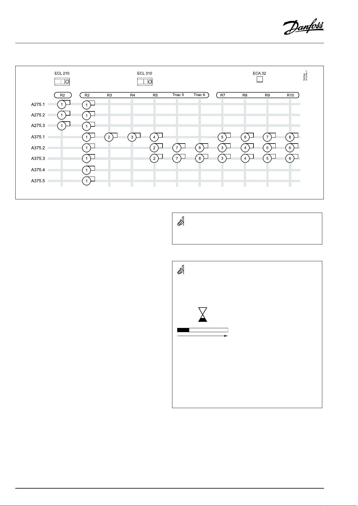
Burnercontroloverview:
R2–R10=relaynos.inECL/ECA32
Seethesection‘Electricalconnections’formoredetailedinformation.
Applicationkeysmightbereleasedbeforealldisplaytextsare
translated.InthiscasethetextisinEnglish.
Automaticupdateofcontrollersoftware(firmware):
Thesoftwareofthecontrollerisupdatedautomaticallywhenthekey
isinserted(asofcontrollerversion1.11(ECL210/310)andversion
1.58(ECL296)).Thefollowinganimationwillbeshownwhenthe
softwareisbeingupdated:
Progressbar
Duringupdate:
•DonotremovetheKEY
Ifthekeyisremovedbeforethehour-glassisshown,youhave
tostartafresh.
•Donotdisconnectthepower
Ifthepowerisinterruptedwhenthehour-glassisshown,the
controllerwillnotwork.
•Manualupdateofcontrollersoftware(firmware):
Seethesection"Automatic/manualupdateoffirmware"
4|©Danfoss|2021.04
AQ042286456873en-010501
Page 5
OperatingGuideECLComfort210/296/310,applicationA275/A375
SafetyNote
Toavoidinjuryofpersonsanddamagestothedevice,itisabsolutely
necessarytoreadandobservetheseinstructionscarefully.
Necessaryassembly,start-up,andmaintenanceworkmustbe
performedbyqualifiedandauthorizedpersonnelonly.
Locallegislationsmustberespected.Thiscomprisesalsocable
dimensionsandtypeofisolation(doubleisolatedat230V).
AfusefortheECLComfortinstallationismax.10Atypically.
TheambienttemperaturerangesforECLComfortinoperationare:
ECLComfort210/310:0-55°C
ECLComfort296:0-45°C.
Exceedingthetemperaturerangecanresultinmalfunctions.
Installationmustbeavoidedifthereisariskforcondensation(dew).
Thewarningsignisusedtoemphasizespecialconditionsthatshould
betakenintoconsideration.
Thissymbolindicatesthatthisparticularpieceofinformationshould
bereadwithspecialattention.
AsthisOperatingGuidecoversseveralsystemtypes,specialsystem
settingswillbemarkedwithasystemtype.Allsystemtypesareshown
inthechapter:'Identifyingyoursystemtype'.
°C(degreesCelsius)isameasuredtemperaturevaluewhereasK
(Kelvin)oftenisusedfortemperaturedifferences.
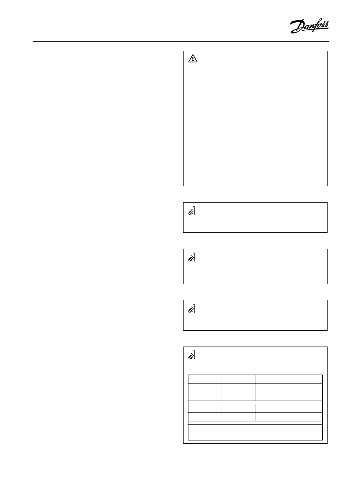
TheIDno.isuniquefortheselectedparameter.
ExampleFirstdigitSeconddigitLastthreedigits
1117411174
-
Circuit1Parameterno.
12174
IfanIDdescriptionismentionedmorethanonce,itmeansthatthere
arespecialsettingsforoneormoresystemtypes.Itwillbemarked
withthesystemtypeinquestion(e.g.12174-A266.9).
1
-
2
Circuit2Parameterno.
AQ042286456873en-010501
174
©Danfoss|2021.04|5
Page 6
OperatingGuideECLComfort210/296/310,applicationA275/A375
ParametersindicatedwithanIDno.like"1x607"meanauniversal
parameter.
xstandsforcircuit/parametergroup.
DisposalNote
Thissymbolontheproductindicatesthatitmaynot
bedisposedofashouseholdwaste.
Itmustbehandedovertotheapplicabletake-back
schemefortherecyclingofelectricalandelectronic
equipment.
•Disposeoftheproductthroughchannelsprovided
forthispurpose.
•Complywithalllocalandcurrentlyapplicablelaws
andregulations.
6|©Danfoss|2021.04
AQ042286456873en-010501
Page 7
OperatingGuideECLComfort210/296/310,applicationA275/A375
2.0Installation
2.1Beforeyoustart
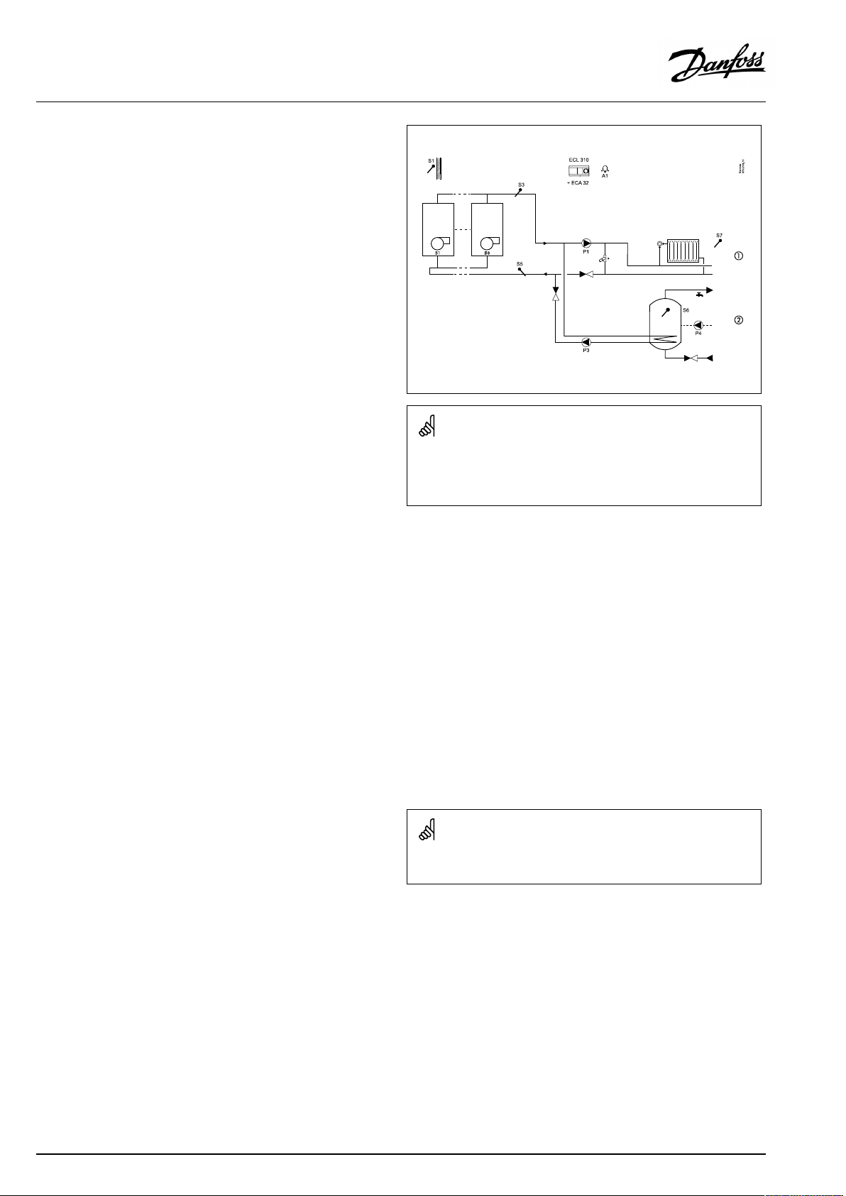
TheapplicationA275.1isveryflexible.Thesearethebasic
principles:
Heating(circuit1):
Typically,theboilertemperatureisadjustedaccordingtoyour
requirements.TheboilertemperaturesensorS3isthemost
importantsensor.Itmustbeplacedcorrectlyinordertomeasure
theboilertemperature.ThedesiredboilertemperatureatS3is
calculatedintheECLcontroller,basedontheoutdoortemperature
(S1)andthedesiredroomtemperature.Thelowertheoutdoor
temperature,thehigherthedesiredboilertemperature.Theboiler
temperatureisalsotheflowtemperatureinthedirectconnected
heatingcircuit.
Bymeansofaweekschedule(upto3‘Comfort’periods/day),the
heatingcircuitcanbein‘Comfort’or‘Saving’mode(twodifferent
temperaturevaluesforthedesiredroomtemperature).In'Saving'
modea'Totalstop'functioncanbeselectedinordertoswitchOFF
theheating.
TheburnerisswitchedONwhentheboilertemperatureis
lowerthanthedesiredboilertemperatureandswitchedOFF
whentheboilertemperatureishigherthanthedesiredboiler
temperature.AswitchingdifferencedeterminestheON/OFF
control.Furthermore,theboilerprotectionfunctionwillonly
switchONthecirculationpumpiftheboilertemperaturegets
aboveaminimumtemperature.AminimumON-timecanbesetfor
theburnerinordertoincreasetheboiler'sefficiency.
Thereturntemperature(S5)totheboilershouldnotbetoo
high(condensingboiler)ortoolow(oilorgasfiredboiler).Ifso,
thedesiredboilertemperaturecanbedecreasedorincreased.
Furthermore,thereturntemperaturelimitationcanbedependent
ontheoutdoortemperature.Typically,thelowertheoutdoor
temperature,thehighertheacceptedreturntemperature.
Ifthemeasuredroomtemperature(measuredbyS7ortheremote
controlunitECA30)doesnotequalthedesiredroomtemperature,
thedesiredboilertemperaturecanbeadjusted.
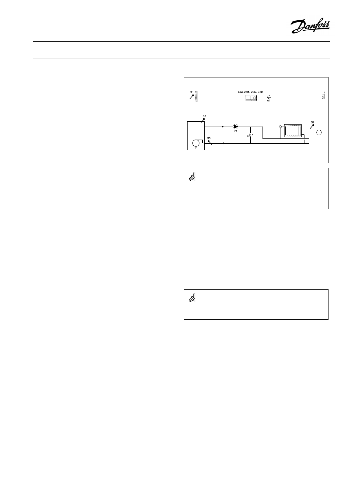
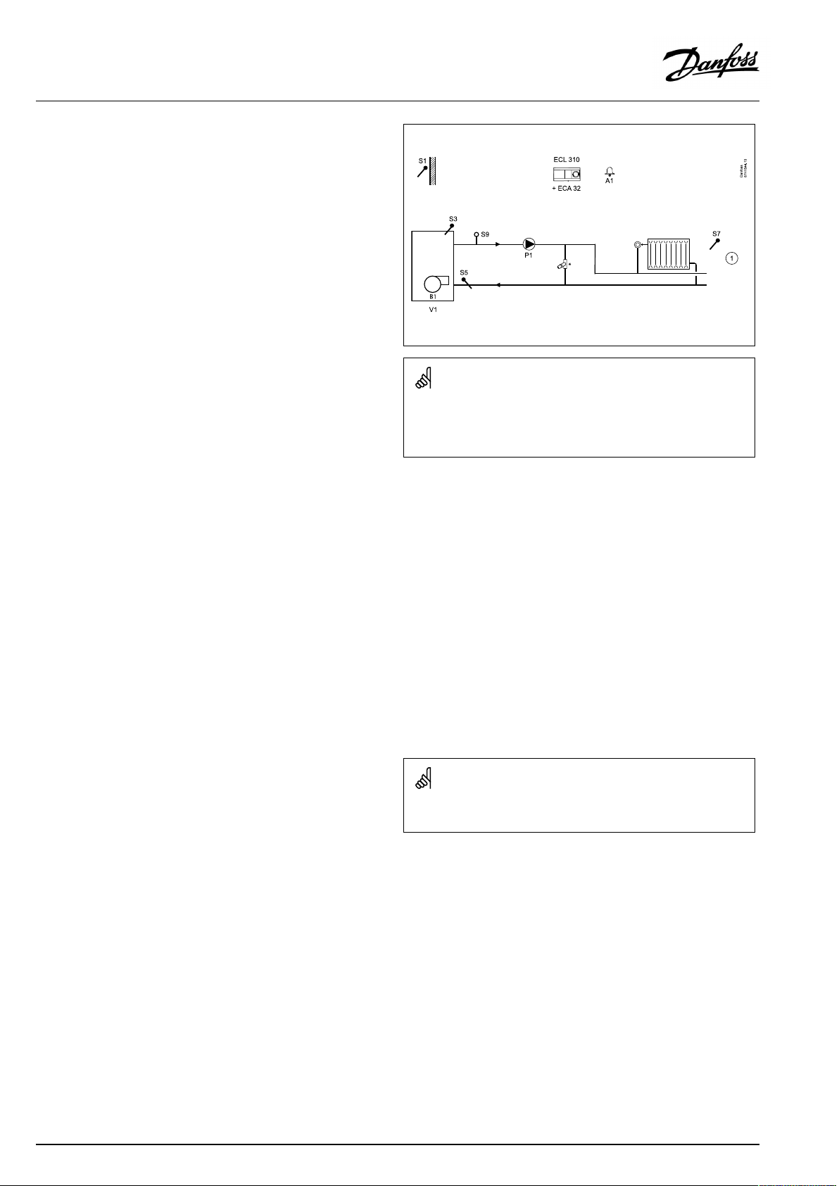
TypicalA275.1application:
*Pressurereliefvalve
Theshowndiagramisafundamentalandsimplifiedexampleanddoes
notcontainallcomponentsthatarenecessaryinasystem.
AllnamedcomponentsareconnectedtotheECLComfortcontroller.
Listofcomponents:
S1
Outdoortemperaturesensor
S3
(mandatory)Boilertemperaturesensor
S5Returntemperaturesensor
S7
Roomtemperaturesensor/ECA30
P1
Circulationpump
B1Burner
A1
Alarm
Thecirculationpump(P1)isONatheatdemandoratfrost
protection.
TheheatingcanbeswitchedOFFiftheoutdoortemperaturegets
higherthanasetvalue.
AQ042286456873en-010501
Thecontrollerispre-programmedwithfactorysettingsthatareshown
intherelevantchaptersofthisguide.
©Danfoss|2021.04|7
Page 8
OperatingGuideECLComfort210/296/310,applicationA275/A375
TheapplicationA275.2isveryflexible.Thesearethebasic
principles:
Heating(circuit1):
Typically,theboilertemperatureisadjustedaccordingtoyour
requirements.TheboilertemperaturesensorS3isthemost
importantsensor.Itmustbeplacedcorrectlyinordertomeasure
theboilertemperature.ThedesiredboilertemperatureatS3is
calculatedintheECLcontroller,basedontheoutdoortemperature
(S1)andthedesiredroomtemperature.Thelowertheoutdoor
temperature,thehigherthedesiredboilertemperature.Theboiler
temperatureisalsotheflowtemperatureinthedirectconnected
heatingcircuit.
Bymeansofaweekschedule(upto3‘Comfort’periods/day),the
heatingcircuitcanbein‘Comfort’or‘Saving’mode(twodifferent
temperaturevaluesforthedesiredroomtemperature).In'Saving'
modea'Totalstop'functioncanbeselectedinordertoswitchOFF
theheating.
TheburnerisswitchedONwhentheboilertemperatureis
lowerthanthedesiredboilertemperatureandswitchedOFF
whentheboilertemperatureishigherthanthedesiredboiler
temperature.AswitchingdifferencedeterminestheON/OFF
control.Furthermore,theboilerprotectionfunctionwillonly
switchONthecirculationpumpiftheboilertemperaturegets
aboveaminimumtemperature.AminimumON-timecanbesetfor
theburnerinordertoincreasetheboiler'sefficiency.
Thereturntemperature(S5)totheboilershouldnotbetoo
high(condensingboiler)ortoolow(oilorgasfiredboiler).Ifso,
thedesiredboilertemperaturecanbedecreasedorincreased.
Furthermore,thereturntemperaturelimitationcanbedependent
ontheoutdoortemperature.Typically,thelowertheoutdoor
temperature,thehighertheacceptedreturntemperature.
Ifthemeasuredroomtemperature(measuredbyS7ortheremote
controlunitECA30)doesnotequalthedesiredroomtemperature,
thedesiredboilertemperaturecanbeadjusted.
Thecirculationpump(P1)isONatheatdemandoratfrost
protection.
TheheatingcanbeswitchedOFFiftheoutdoortemperaturegets
higherthanasetvalue.
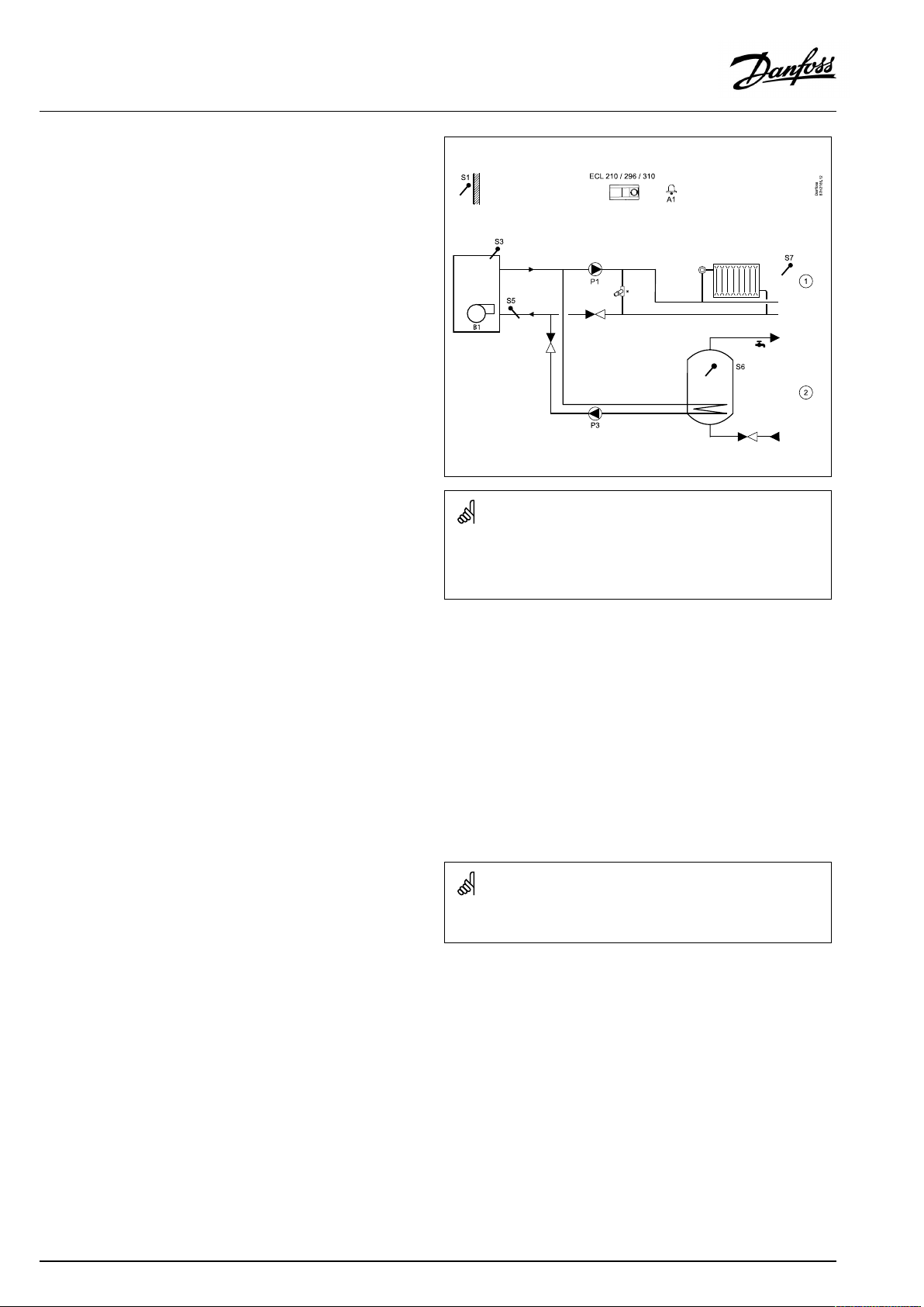
TypicalA275.2application:
*Pressurereliefvalve
Theshowndiagramisafundamentalandsimplifiedexampleanddoes
notcontainallcomponentsthatarenecessaryinasystem.
AllnamedcomponentsareconnectedtotheECLComfortcontroller.
Listofcomponents:
S1
Outdoortemperaturesensor
S3
(mandatory)Boilertemperaturesensor
S5Returntemperaturesensor
S6
DHWtanktemperaturesensor
S7
Roomtemperaturesensor/ECA30
P1
Circulationpump,heating
B1Burner
P3
DHWheatingpump
A1
Alarm
8|©Danfoss|2021.04
Thecontrollerispre-programmedwithfactorysettingsthatareshown
intherelevantchaptersofthisguide.
AQ042286456873en-010501
Page 9
OperatingGuideECLComfort210/296/310,applicationA275/A375
A275.2,basicprinciples,continued:
DHW(circuit2):
Bymeansofaweekschedule(upto3‘Comfort’periods/day),the
DHWcircuitcanbein‘Comfort’or‘Saving’mode(twodifferent
temperaturevaluesfordesiredDHWtemperature).
IfthemeasuredDHWtemperature(S6)islowerthanthedesired
DHWtemperature,theDHWheatingprocedurestarts:
•ThecirculationpumpP1intheheatingcircuitisswitchedOFF
•TheDHWheatingpumpP3isswitchedON
•ThedesiredboilertemperatureatS3isincreased.
Thedesiredboilertemperatureistypically10-15degreeshigher
thanthedesiredDHWtemperature.
WhenthemeasuredDHWtemperature(S6)getshigherthanthe
desiredDHWtemperature,theDHWheatingpump(P3)isswitched
OFF.StartandstopdifferencesdeterminetheON/OFFcontrol.A
post-runtimecanbeset.
Ananti-bacteriafunctionisavailableforactivationontheselected
daysoftheweek.
TheDHWheatinghaspriority,i.e.pumpP3isONandpumpP1is
OFF.Iftheapplicationhasachangeovervalve(priorityvalve)for
theDHWheating,thecirculationpumpP1isstillONduringDHW
heating.
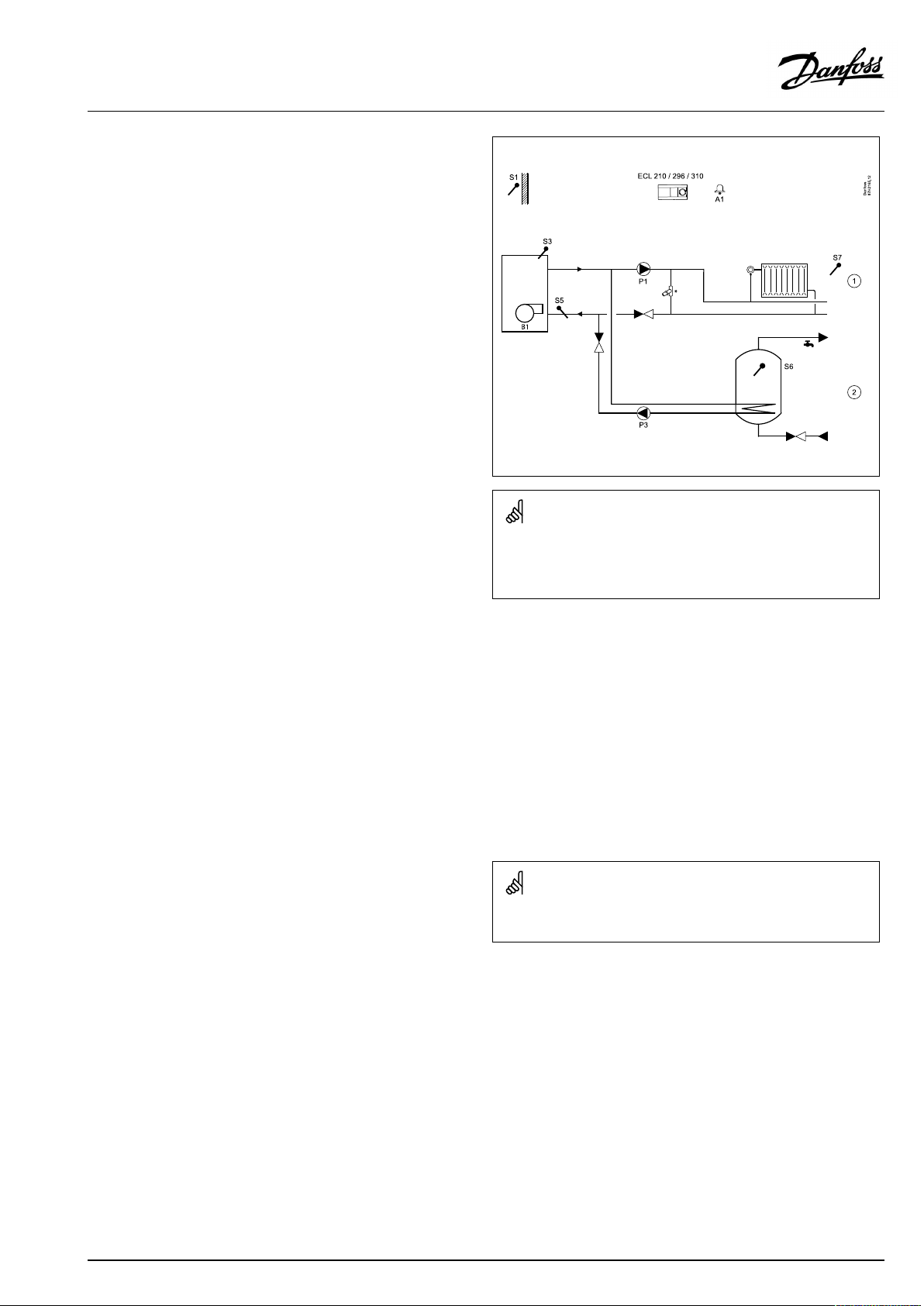
TypicalA275.2application:
*Pressurereliefvalve
Theshowndiagramisafundamentalandsimplifiedexampleanddoes
notcontainallcomponentsthatarenecessaryinasystem.
AllnamedcomponentsareconnectedtotheECLComfortcontroller.
Listofcomponents:
S1
Outdoortemperaturesensor
S3
(mandatory)Boilertemperaturesensor
S5Returntemperaturesensor
S6
DHWtanktemperaturesensor
S7
Roomtemperaturesensor/ECA30
P1
Circulationpump,heating
B1Burner
P3
DHWheatingpump
A1
Alarm
Thecontrollerispre-programmedwithfactorysettingsthatareshown
intherelevantchaptersofthisguide.
AQ042286456873en-010501
©Danfoss|2021.04|9
Page 10
OperatingGuideECLComfort210/296/310,applicationA275/A375
TheapplicationA275.3isveryflexible.Thesearethebasic
principles:
Heating(circuit1):
Typically,theboilertemperatureisadjustedaccordingtoyour
requirements.TheboilertemperaturesensorS3isthemost
importantsensor.Itmustbeplacedcorrectlyinordertomeasure
theboilertemperature.ThedesiredboilertemperatureatS3is
calculatedintheECLcontroller,basedontheoutdoortemperature
(S1)andthedesiredroomtemperature.Thelowertheoutdoor
temperature,thehigherthedesiredboilertemperature.Theboiler
temperatureisalsotheflowtemperatureinthedirectconnected
heatingcircuit.
Bymeansofaweekschedule(upto3‘Comfort’periods/day),the
heatingcircuitcanbein‘Comfort’or‘Saving’mode(twodifferent
temperaturevaluesforthedesiredroomtemperature).In'Saving'
modea'Totalstop'functioncanbeselectedinordertoswitchOFF
theheating.
TheburnerisswitchedONwhentheboilertemperatureis
lowerthanthedesiredboilertemperatureandswitchedOFF
whentheboilertemperatureishigherthanthedesiredboiler
temperature.AswitchingdifferencedeterminestheON/OFF
control.Furthermore,theboilerprotectionfunctionwillonly
switchONthecirculationpumpiftheboilertemperaturegets
aboveaminimumtemperature.AminimumON-timecanbesetfor
theburnerinordertoincreasetheboiler'sefficiency.
Thereturntemperature(S5)totheboilershouldnotbetoo
high(condensingboiler)ortoolow(oilorgasfiredboiler).Ifso,
thedesiredboilertemperaturecanbedecreasedorincreased.
Furthermore,thereturntemperaturelimitationcanbedependent
ontheoutdoortemperature.Typically,thelowertheoutdoor
temperature,thehighertheacceptedreturntemperature.
Ifthemeasuredroomtemperature(measuredbyS7ortheremote
controlunitECA30)doesnotequalthedesiredroomtemperature,
thedesiredboilertemperaturecanbeadjusted.
Thecirculationpump(P1)isONatheatdemandoratfrost
protection.
TheheatingcanbeswitchedOFFiftheoutdoortemperaturegets
higherthanasetvalue.
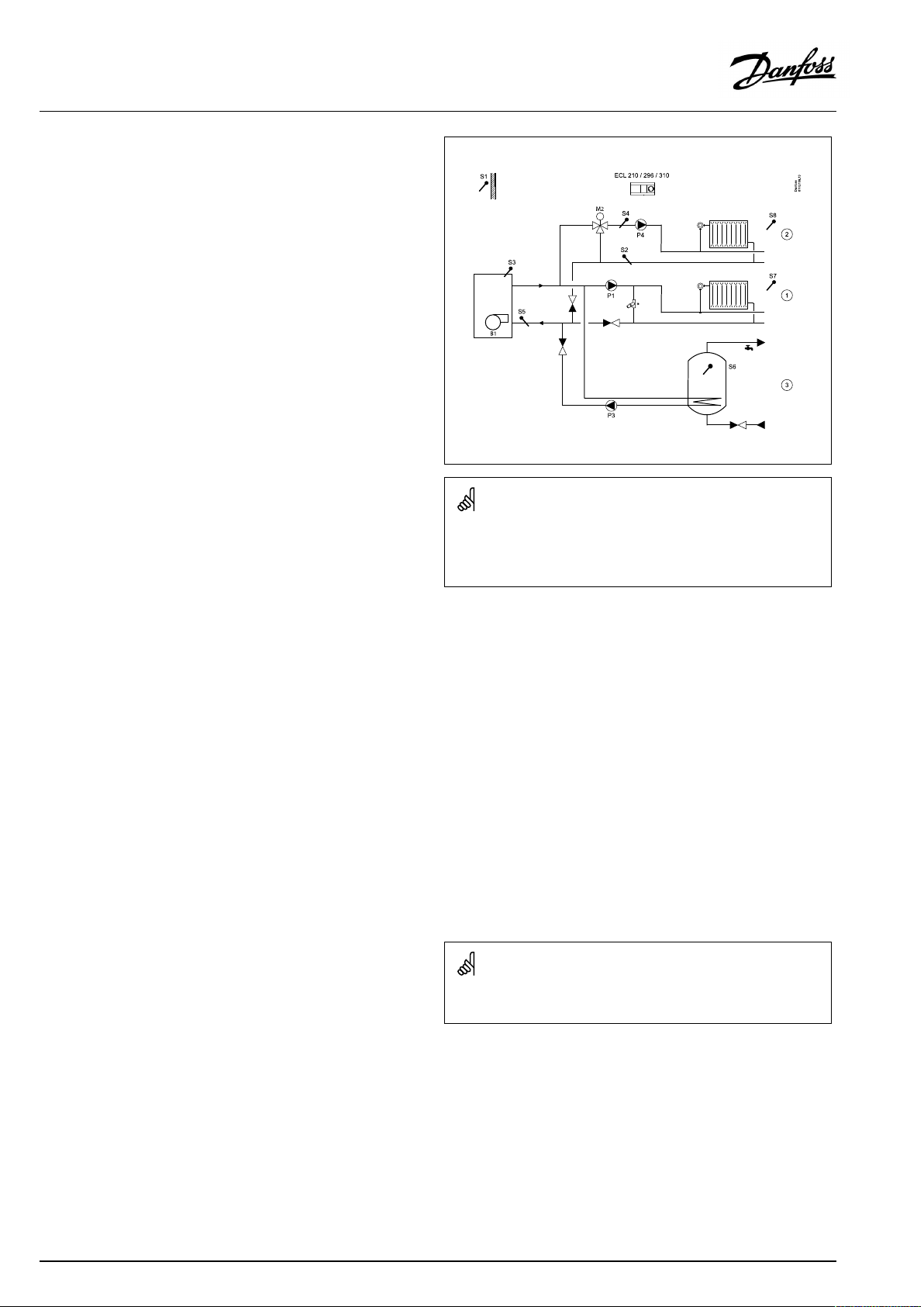
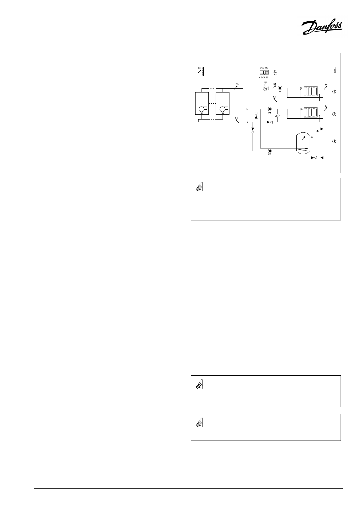
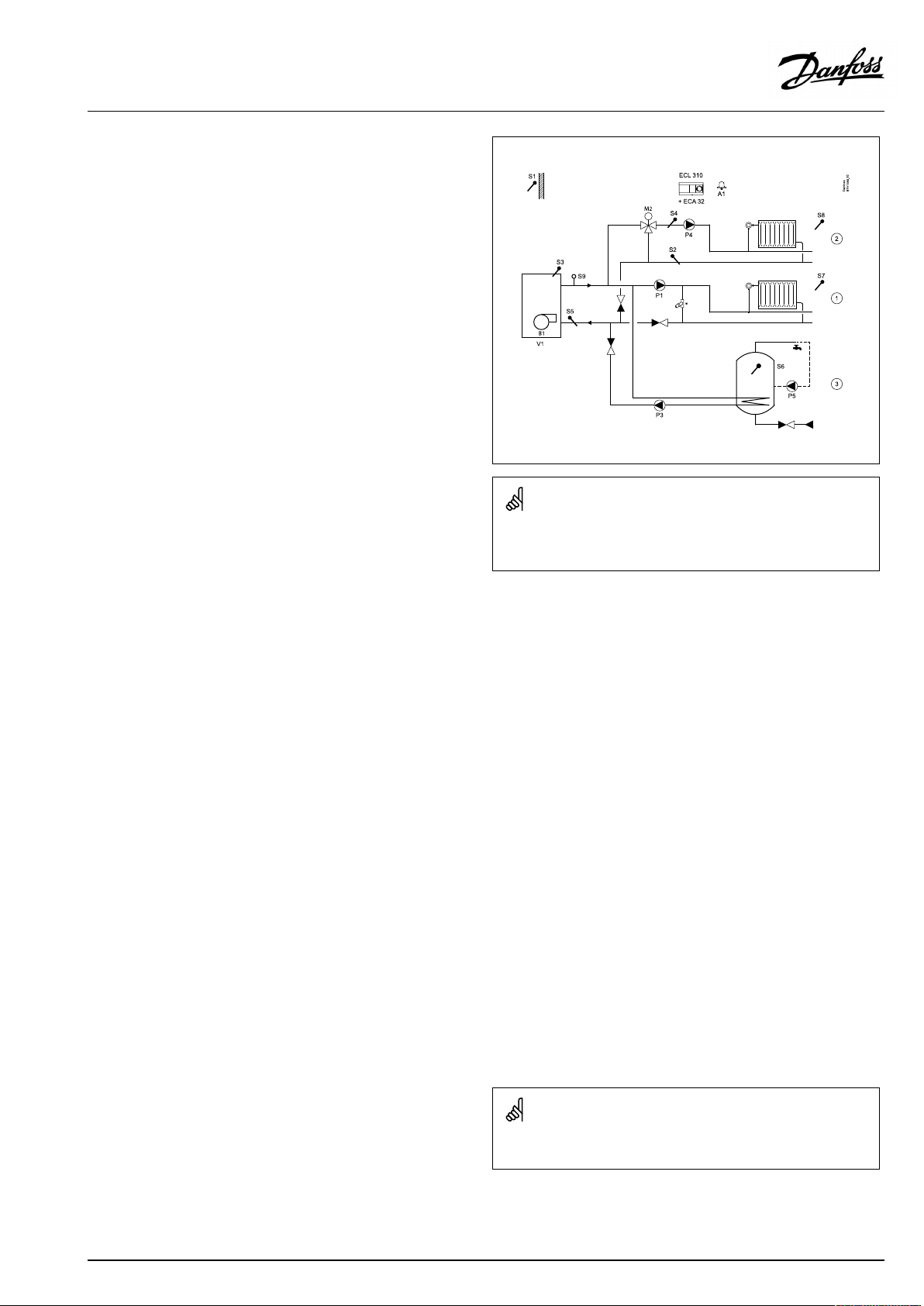
TypicalA275.3application:
*Pressurereliefvalve
Theshowndiagramisafundamentalandsimplifiedexampleanddoes
notcontainallcomponentsthatarenecessaryinasystem.
AllnamedcomponentsareconnectedtotheECLComfortcontroller.
Listofcomponents:
S1
Outdoortemperaturesensor
S2Returntemperaturesensor,circuit2
S3
(mandatory)Boilertemperaturesensor,circuit1
S4
Flowtemperaturesensor,circuit2
S5Returntemperaturesensor,circuit1
S6
DHWtanktemperaturesensor
S7
Roomtemperaturesensor/ECA30,circuit1
S8
Roomtemperaturesensor/ECA30,circuit2
M2
Motorizedcontrolvalve,circuit2
P1
Circulationpump,circuit1
B1Burner
P3
DHWheatingpump,circuit3
P4
Circulationpump,circuit2
10|©Danfoss|2021.04
Thecontrollerispre-programmedwithfactorysettingsthatareshown
intherelevantchaptersofthisguide.
AQ042286456873en-010501
Page 11
OperatingGuideECLComfort210/296/310,applicationA275/A375
A275.3,basicprinciples,continued:
Heating(circuit2):
Typically,theflowtemperatureisadjustedaccordingtoyour
requirements.TheflowtemperaturesensorS4isthemost
importantsensor.ThedesiredflowtemperatureatS4iscalculated
intheECLcontroller,basedontheoutdoortemperature(S1)and
thedesiredroomtemperature.Thelowertheoutdoortemperature,
thehigherthedesiredflowtemperature.
Bymeansofaweekschedule(upto3‘Comfort’periods/day),the
heatingcircuitcanbein‘Comfort’or‘Saving’mode(twodifferent
temperaturevaluesforthedesiredroomtemperature).In'Saving'
modea'Totalstop'functioncanbeselectedinordertoswitchOFF
theheating.
ThemotorizedcontrolvalveM2isopenedgraduallywhentheflow
temperature,S4,islowerthanthedesiredflowtemperatureand
viceversa.
ThedesiredflowtemperatureatS4willtypicallydeterminethe
desiredboilertemperature(S3).
Thereturntemperature(S2)canbelimited.Ifso,thedesiredflow
temperatureatS4canbedecreasedorincreased.
Furthermore,thereturntemperaturelimitationcanbedependent
ontheoutdoortemperature.Typically,thelowertheoutdoor
temperature,thehighertheacceptedreturntemperature.
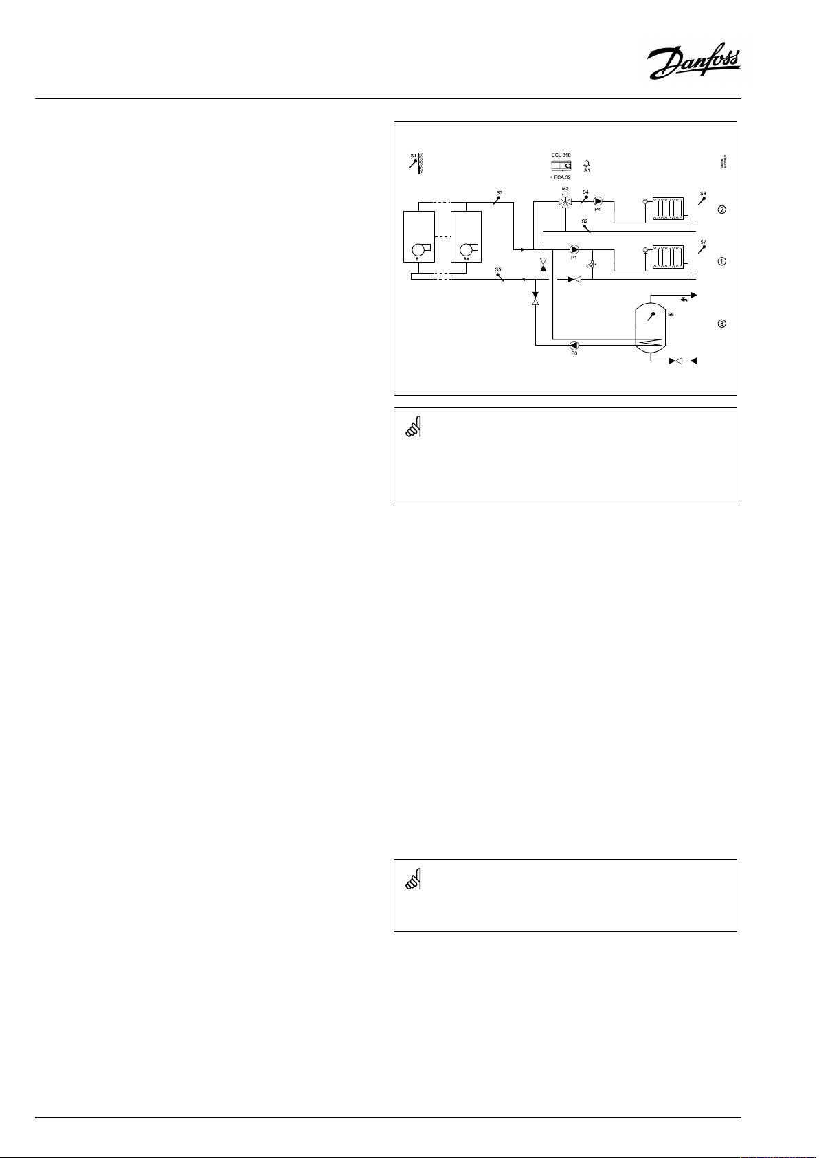
TypicalA275.3application:
*Pressurereliefvalve
Theshowndiagramisafundamentalandsimplifiedexampleanddoes
notcontainallcomponentsthatarenecessaryinasystem.
AllnamedcomponentsareconnectedtotheECLComfortcontroller.
Ifthemeasuredroomtemperature(measuredbyS8ortheremote
controlunitECA30)doesnotequalthedesiredroomtemperature,
thedesiredflowtemperaturecanbeadjusted.
Thecirculationpump(P4)isONatheatdemandoratfrost
protection.
TheheatingcanbeswitchedOFFwhentheoutdoortemperatureis
higherthanaselectablevalueoraDHWheatingpriorityispresent.
Listofcomponents:
S1
Outdoortemperaturesensor
S2Returntemperaturesensor,circuit2
S3
(mandatory)Boilertemperaturesensor,circuit1
S4
Flowtemperaturesensor,circuit2
S5Returntemperaturesensor,circuit1
S6
DHWtanktemperaturesensor
S7
Roomtemperaturesensor/ECA30,circuit1
S8
Roomtemperaturesensor/ECA30,circuit2
M2
Motorizedcontrolvalve,circuit2
P1
Circulationpump,circuit1
B1Burner
P3
DHWheatingpump,circuit3
P4
Circulationpump,circuit2
Thecontrollerispre-programmedwithfactorysettingsthatareshown
intherelevantchaptersofthisguide.
AQ042286456873en-010501
©Danfoss|2021.04|11
Page 12

OperatingGuideECLComfort210/296/310,applicationA275/A375
A275.3,basicprinciples,continued:
DHW(circuit3):
Bymeansofaweekschedule(upto3‘Comfort’periods/day),the
DHWcircuitcanbein‘Comfort’or‘Saving’mode(twodifferent
temperaturevaluesfordesiredDHWtemperature).
IfthemeasuredDHWtemperature(S6)islowerthanthedesired
DHWtemperature,theDHWheatingprocedurestarts:
•ThecirculationpumpP1intheheatingcircuitisswitchedOFF
•TheDHWheatingpumpP3isswitchedON
•ThedesiredboilertemperatureatS3isincreased.
Thedesiredboilertemperatureistypically10-15degreeshigher
thanthedesiredDHWtemperature.
WhenthemeasuredDHWtemperature(S6)getshigherthanthe
desiredDHWtemperature,theDHWheatingpump(P3)isswitched
OFF.StartandstopdifferencesdeterminetheON/OFFcontrol.A
post-runtimecanbeset.
Ananti-bacteriafunctionisavailableforactivationontheselected
daysoftheweek.
TheDHWheatinghaspriority,i.e.pumpP3isONandpumpP1is
OFF.Iftheapplicationhasachangeovervalve(priorityvalve)for
theDHWheating,thecirculationpumpP1isstillONduringDHW
heating.
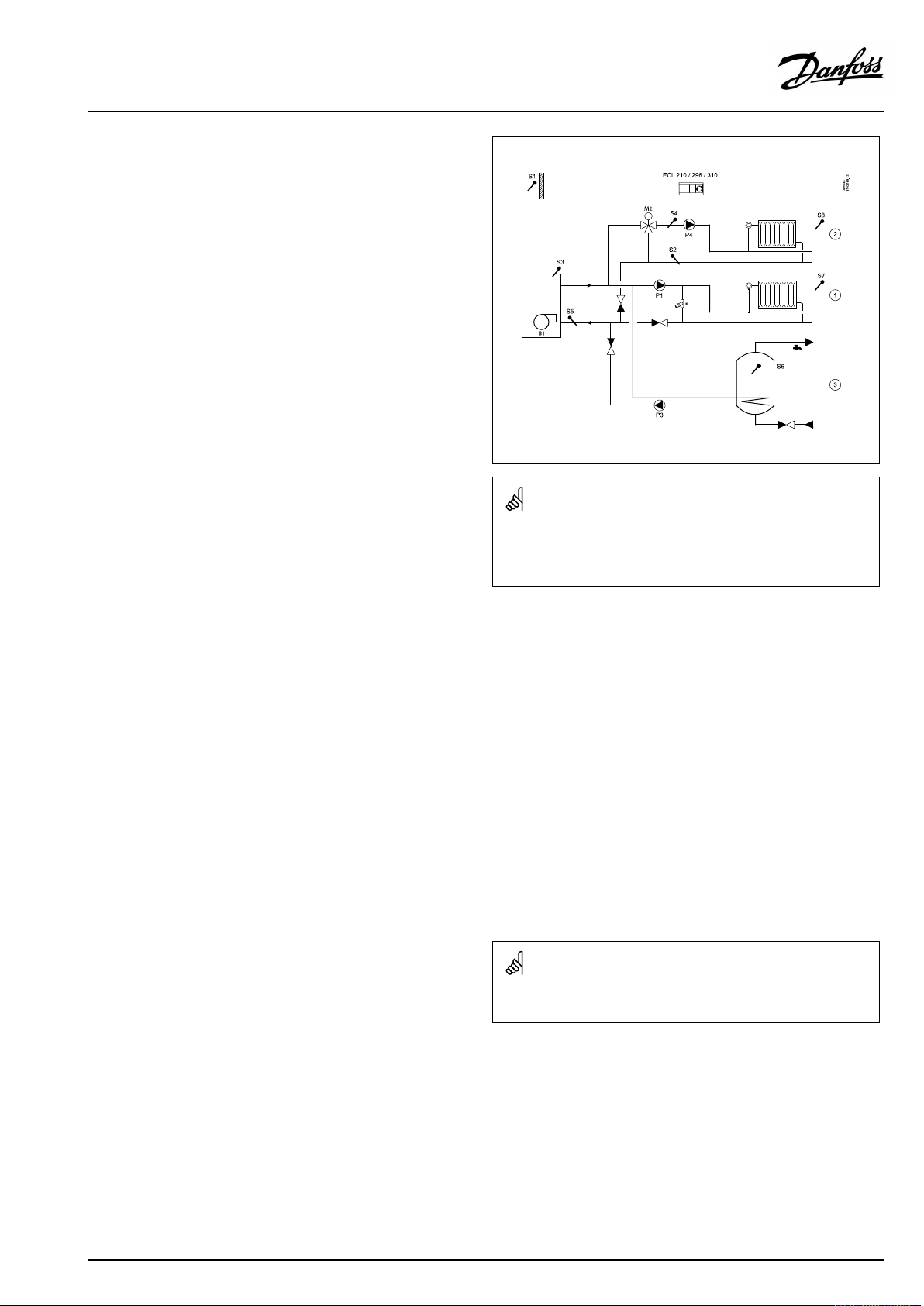
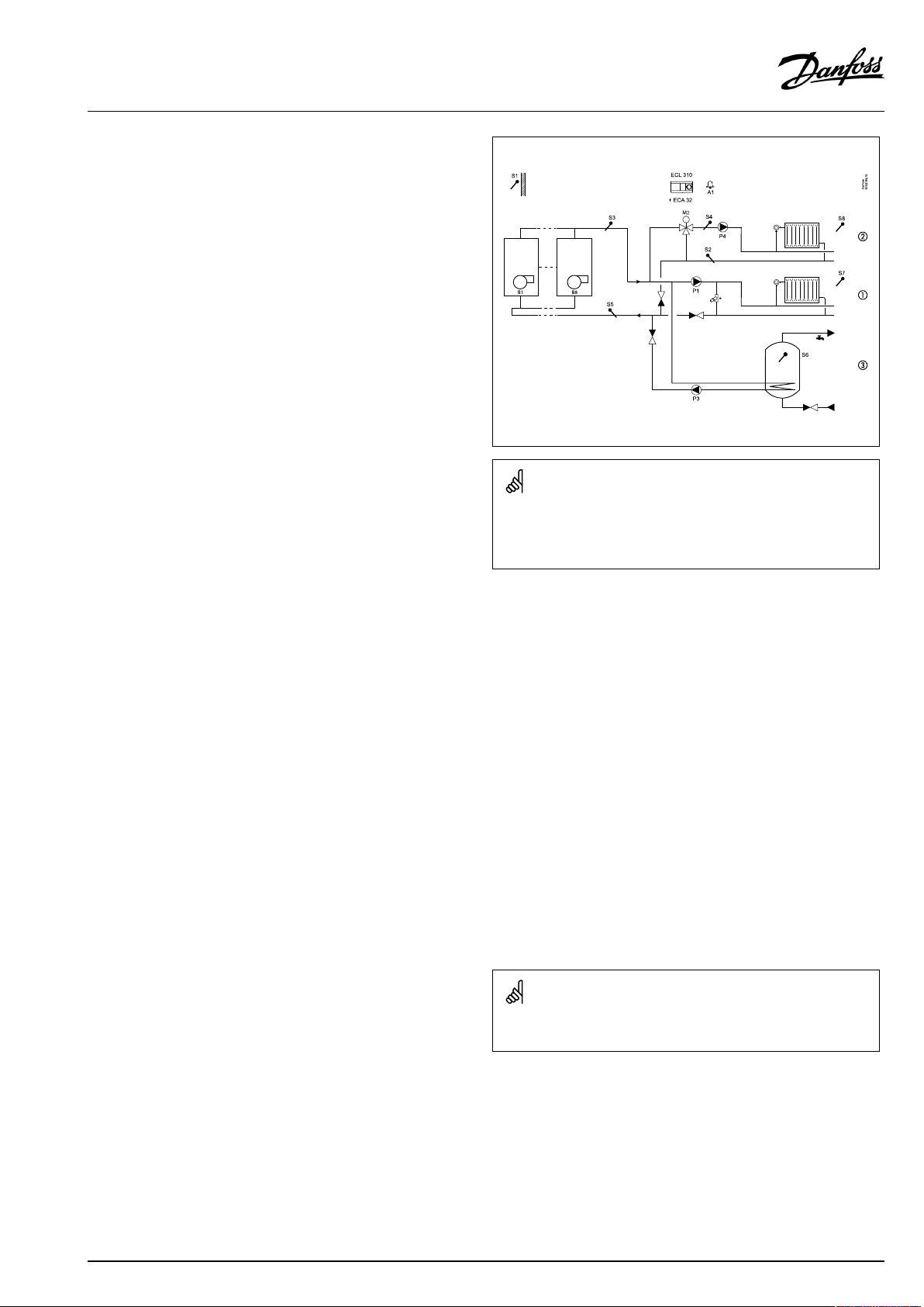
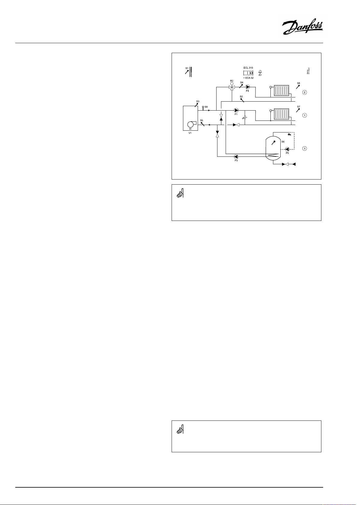
TypicalA275.3application:
*Pressurereliefvalve
Theshowndiagramisafundamentalandsimplifiedexampleanddoes
notcontainallcomponentsthatarenecessaryinasystem.
AllnamedcomponentsareconnectedtotheECLComfortcontroller.
Listofcomponents:
S1
Outdoortemperaturesensor
S2Returntemperaturesensor,circuit2
S3
(mandatory)Boilertemperaturesensor,circuit1
S4
Flowtemperaturesensor,circuit2
S5Returntemperaturesensor,circuit1
S6
DHWtanktemperaturesensor
S7
Roomtemperaturesensor/ECA30,circuit1
S8
Roomtemperaturesensor/ECA30,circuit2
M2
Motorizedcontrolvalve,circuit2
P1
Circulationpump,circuit1
B1Burner
P3
DHWheatingpump,circuit3
P4
Circulationpump,circuit2
Thecontrollerispre-programmedwithfactorysettingsthatareshown
intherelevantchaptersofthisguide.
12|©Danfoss|2021.04
AQ042286456873en-010501
Page 13

OperatingGuideECLComfort210/296/310,applicationA275/A375
ApplicationA275ingeneral:
UptotwoRemoteControlUnits,ECA30/31,canbeconnectedto
oneECLcontrollertocontroltheECLcontrollerremotely.
Exerciseofcirculationpumpsandcontrolvalveinperiodswithout
heatingdemandcanbearranged.
AdditionalECLComfortcontrollerscanbeconnectedviatheECL
485bustoutilizecommonoutdoortemperaturesignal,timeand
datesignals.
SeveralECLcontrollers,internallyconnectedviaECL485bus,work
inMaster/Slaveconnection.InaMaster/Slavesystemmaximum
2ECA30/31canbepresent.
Unusedinput(fromS7andup)can,bymeansofanoverride
switch,beusedtooverridethescheduletoafixed'Comfort'or
'Saving'mode.
Modbuscommunication(ECL296andECL310)toaSCADAsystem
canbeestablished.
ECLPortal,Internetbasedconnection,allowsECL296,310and
310Btobemonitoredandcontrolledremotelyviastandard
Internetbrowsers(forexampleInternetExplorer,GoogleChrome
andSafari).
Heat-meters:
Upto5heat-meterscanbeconnectedtotheM-busterminals(ECL
296/310).
DatacanbetransferredtotheSCADAsystemviaModbusandTCP/
IPtotheECLPortal.
ModbuscommunicationtoaSCADAsystemcanbeestablished.
TheM-busdata(ECLComfort296/310)canfurthermorebe
transferredtotheModbuscommunication.
Alarm,A275.1andA275.2:
AlarmA1(relayR4)andthealarmsymbol(
•ifatemperaturesensororitsconnectiondisconnects/
shortcircuits.
Alarm,A275.3:
Thealarmsymbol(
•iftheactualflowtemperatureatS4(heatingcircuit2),differs
fromthedesiredflowtemperature.
•ifatemperaturesensororitsconnectiondisconnects/
short-circuits.
)canbeactivated:
)canbeactivated:
AQ042286456873en-010501
©Danfoss|2021.04|13
Page 14

OperatingGuideECLComfort210/296/310,applicationA275/A375
ApplicationA275ingeneral,continued:
Offsetadjustment
Ameasuredtemperaturecanbeoffsetadjusted,ifneeded.
(Navigation:MENU>Commoncontroller>System>Sensoroffset)
Inputconfiguration
Inputs(asfromS7andup),whicharenotpartoftheapplication
canbeconfiguredtobePt1000,0-10Volt,frequency(pulse
counter)ordigitalinput.ThisfeaturemakesitpossibleinECL296/
310tocommunicateextrasignals,suchastemperatures,pressures,
ON/OFFconditions,viaModbusandECLPortal.
TheconfigurationisdonebymeansoftheECLTool(freesoftware
fordownload)ordirectlyinadedicatedmenuintheECLPortalor
theconnectionforModbus(BMS/SCADA).
Applicationupload
Theapplicationuploadprocedureisthefollowingafterhaving
powereduptheECLComfortcontroller:
1.Inserttheapplicationkey
2.Selectlanguage,*1,*2
3.Selectsubtype(theInstallationGuideshowssubtypes)
4.SetTimeandDate
TheECLComfortcontrollerinstallstheapplication,initializesand
restarts.Outputrelaysareactivated/de-activated(click-sounds
fromthiscanbeheard).Thisalsomeansthat,forexample,
circulationpumpscanbeswitchedONandOFFshortly.
*1:Seealsosection"InsertingtheECLApplicationKey" .
*2:(ECLComfort310,24Volt)Iflanguagecannotbeselected,the
powersupplyisnota.c.(alternatingcurrent).
Commissioning
WhentheselectedapplicationhasbeenuploadedtheECLComfort
controllerstartsinManualmode.Thiscanbeusedtoverifycorrect
connectionsof,forexample,temperature,pressureandflow
sensors.Alsoverifyingthecontrolledcomponents(valveactuators,
pumps,burneretc.)forcorrectfunctionalitycanbedone.
Theapplicationkeyisdeliveredwithfactorysettings.
Dependingonsystemtype,itmightbenecessarytochangesome
factorysettingsindividuallyforoptimizingthefunctionality.
Theapplicationkeymustbeinsertedforchangingsettings.
Power-down/power-up
WhenthepowersupplytotheECLComfortcontrolleris
disconnected(power-down),theoutputrelaysgotode-activated
position.
Thismeansthat,forexample,circulationpumpsandburnercanbe
switchedON.
SeetheelectricalconnectiondiagramsintheInstallationGuide.
Allrelaycontactsareshowninde-activatedsituation.Somerelay
contactsareclosed,somerelaycontactsareopen.
WhenthepowersupplytotheECLComfortcontrolleris
re-established(power-up),theoutputrelaysareactivated/
de-activated(click-soundsfromthiscanbeheard).Thisalsomeans
that,forexample,circulationpumpsandburnercanbeswitched
ONandOFFshortly.
ImportantforA275.3:
•Setthecorrectrunningtime"Mrun"oftheMotorizedControl
ValveM2.(Circuit2>MENU>Settings>Controlparameters
>Mrun).
14|©Danfoss|2021.04
AQ042286456873en-010501
Page 15

OperatingGuideECLComfort210/296/310,applicationA275/A375
Thecontrollerispre-programmedwithfactorysettingsthatareshown
inthe‘ParameterIDoverview’appendix.
AQ042286456873en-010501
©Danfoss|2021.04|15
Page 16
OperatingGuideECLComfort210/296/310,applicationA275/A375
TheapplicationA375.1isveryflexible.Thesearethebasic
principles:
TheapplicationsA375.1/A375.2/A375.3canON/OFFcontrolup
to8burnersteps.
InapplicationA375.1thefirst4burnerstepsarecontrolledby
relaysintheECL310.Thenext,max.4burnersteps,arecontrolled
byrelaysintheextensionmoduleECA32(placedinthebasepart
oftheECL310).
Heating(circuit1):
Typically,thecommonboilertemperatureisadjustedaccordingto
yourrequirements.TheboilertemperaturesensorS3isthemost
importantsensor.Itmustbeplacedcorrectlyinordertomeasure
thecommonboilertemperature.Thedesiredboilertemperature
atS3iscalculatedintheECLcontroller,basedontheoutdoor
temperature(S1)andthedesiredroomtemperature.Thelowerthe
outdoortemperature,thehigherthedesiredboilertemperature.
Theboilertemperatureisalsotheflowtemperatureinthedirect
connectedheatingcircuit.
Bymeansofaweekschedule(upto3‘Comfort’periods/day),the
heatingcircuitcanbein‘Comfort’or‘Saving’mode(twodifferent
temperaturevaluesforthedesiredroomtemperature).In'Saving'
modea'Totalstop'functioncanbeselectedinordertoswitchOFF
theheating.
ThefirstburnerstepisswitchedONwhenthecommonboiler
temperatureislowerthanthedesiredboilertemperature.The
controllerobservesthecommonboilertemperatureandswitches
ONthenextburnerstepifthecommonboilertemperaturedoes
notincreasesatisfactorily.TheswitchingOFFprocedureofburner
stepsisviceversa.AswitchingdifferencedeterminestheON/OFF
control.
Theburnerscanbecontrolledin:
•fixedsequence(example:Always1-2-3-4-5)or
•automaticrotatingsequence(example:Firstperiod:1-2-3-4-5,
secondperiod:2-3-4-5-1,thirdperiod:3-4-5-1-2andsoon)
•semi-automaticrotatingsequence(example:Firstperiod:1,
2-3-4-5,secondperiod:1,3-4-5-2,thirdperiod:1,4-5-2-3and
soon)
Furthermore,theboilerprotectionfunctionwillswitchONthe
circulationpumpwhentheboilertemperaturegetsabovea
minimumvalue.AminimumON-timecanbesetfortheburnerin
ordertoincreasetheboiler'sefficiency.
Thereturntemperature(S5)totheboilershouldnotbetoo
high(condensingboiler)ortoolow(oilorgasfiredboiler).Ifso,
thedesiredboilertemperaturecanbedecreasedorincreased.
Furthermore,thereturntemperaturelimitationcanbedependent
ontheoutdoortemperature.Typically,thelowertheoutdoor
temperature,thehighertheacceptedreturntemperature.
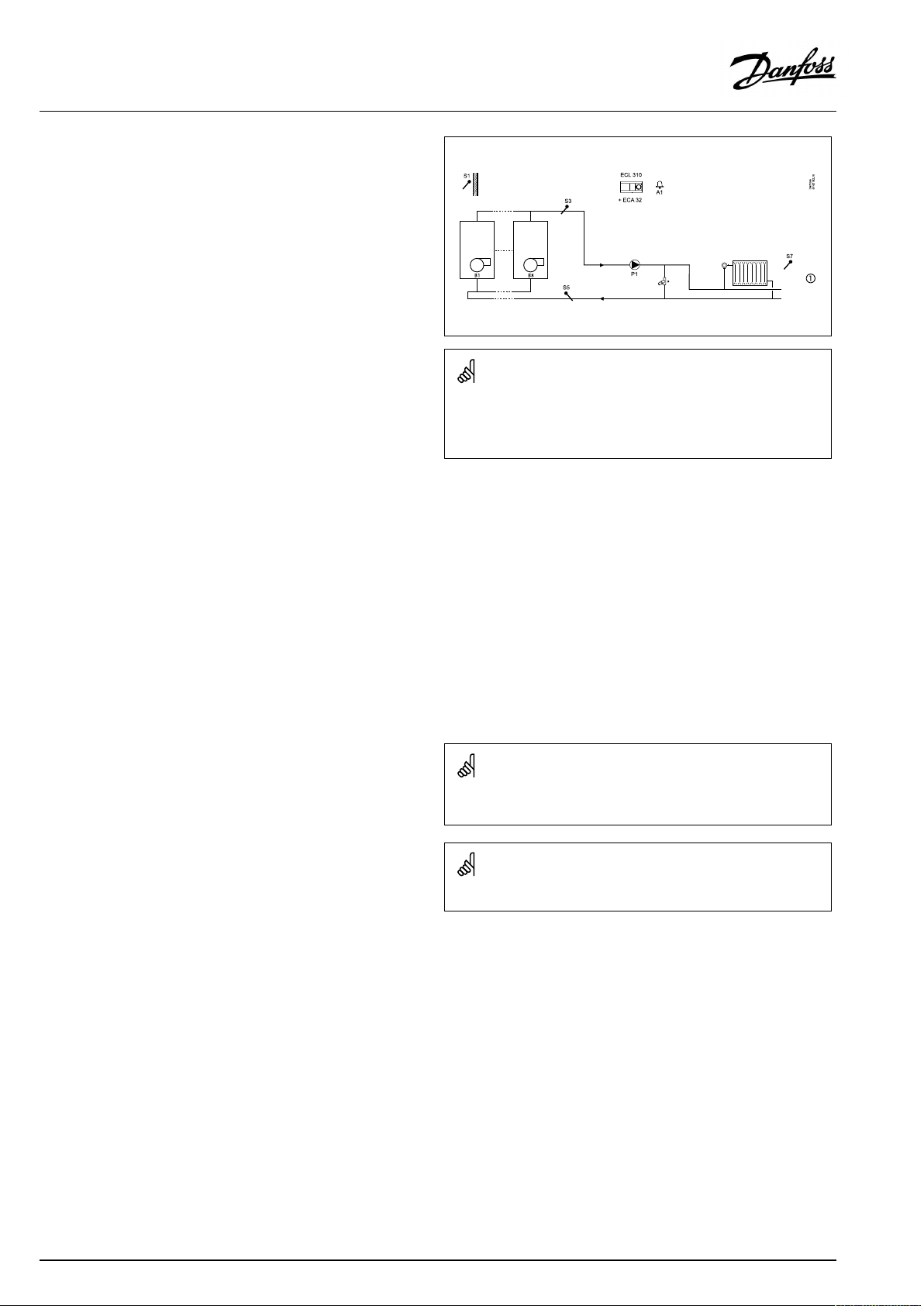
TypicalA375.1application:
*Pressurereliefvalve
Theshowndiagramisafundamentalandsimplifiedexampleanddoes
notcontainallcomponentsthatarenecessaryinasystem.
AllnamedcomponentsareconnectedtotheECLComfortcontroller.
Listofcomponents:
ECL310
ECA32
S1
S3
ElectroniccontrollerECLComfort310
Internalextensionmodulewithrelayoutputs
Outdoortemperaturesensor
(mandatory)Commonboilertemperaturesensor
S5Returntemperaturesensor
S7
(S10)
P1
Roomtemperaturesensor/ECA30
(Externaltemperaturecontrol,notillustrated)
Circulationpump
B1–B8Burner1...8
A1
Thecontrollerispre-programmedwithfactorysettingsthatareshown
intherelevantchaptersofthisguide.
Boilersequencerotation/shifttakesplaceatmidnight.
Alarm
Ifthemeasuredroomtemperature(S7orRemotecontrolunitECA
30)doesnotequalthedesiredroomtemperature,thedesired
boilertemperaturecanbeadjusted.
Thecirculationpump(P1)isONatheatdemandoratfrost
protection.
TheheatingcanbeswitchedOFFwhentheoutdoortemperatureis
higherthanasetvalue.
Thedesiredcommonboilertemperaturecan,viaS10,becontrolled
bymeansofanexternalvoltageintherange0-10volt.
16|©Danfoss|2021.04
AQ042286456873en-010501
Page 17
OperatingGuideECLComfort210/296/310,applicationA275/A375
TheapplicationA375.2isveryflexible.Thesearethebasic
principles:
TheapplicationsA375.1/A375.2/A375.3canON/OFFcontrolup
to8burnersteps.
InapplicationA375.2thefirst2burnerstepsarecontrolledby
relaysintheECL310.Thenext,max.4burnersteps,arecontrolled
byrelaysintheextensionmoduleECA32(placedinthebasepartof
theECL310).Thelast,max.2burnerstepsarecontrolledbytriacs
intheECL310.Auxillaryrelaysmustbeconnectedtothetriacs.
Heating(circuit1):
Typically,thecommonboilertemperatureisadjustedaccordingto
yourrequirements.TheboilertemperaturesensorS3isthemost
importantsensor.Itmustbeplacedcorrectlyinordertomeasure
thecommonboilertemperature.Thedesiredboilertemperature
atS3iscalculatedintheECLcontroller,basedontheoutdoor
temperature(S1)andthedesiredroomtemperature.Thelowerthe
outdoortemperature,thehigherthedesiredboilertemperature.
Theboilertemperatureisalsotheflowtemperatureinthedirect
connectedheatingcircuit.
Bymeansofaweekschedule(upto3‘Comfort’periods/day),the
heatingcircuitcanbein‘Comfort’or‘Saving’mode(twodifferent
temperaturevaluesforthedesiredroomtemperature).In'Saving'
modea'Totalstop'functioncanbeselectedinordertoswitchOFF
theheating.
ThefirstburnerstepisswitchedONwhenthecommonboiler
temperatureislowerthanthedesiredboilertemperature.The
controllerobservesthecommonboilertemperatureandswitches
ONthenextburnerstepifthecommonboilertemperaturedoes
notincreasesatisfactorily.TheswitchingOFFprocedureofburner
stepsisviceversa.AswitchingdifferencedeterminestheON/OFF
control.
Theburnerscanbecontrolledin:
•fixedsequence(example:Always1-2-3-4-5)or
•automaticrotatingsequence(example:Firstperiod:1-2-3-4-5,
secondperiod:2-3-4-5-1,thirdperiod:3-4-5-1-2andsoon)
•semi-automaticrotatingsequence(example:Firstperiod:1,
2-3-4-5,secondperiod:1,3-4-5-2,thirdperiod:1,4-5-2-3and
soon)
Furthermore,theboilerprotectionfunctionwillswitchONthe
circulationpumpwhentheboilertemperaturegetsabovea
minimumvalue.AminimumON-timecanbesetfortheburnerin
ordertoincreasetheboiler'sefficiency.
TypicalA375.2application:
*Pressurereliefvalve
Theshowndiagramisafundamentalandsimplifiedexampleanddoes
notcontainallcomponentsthatarenecessaryinasystem.
AllnamedcomponentsareconnectedtotheECLComfortcontroller.
Listofcomponents:
ECL310
ECA32
S1
S3
ElectroniccontrollerECLComfort310
Internalextensionmodulewithrelayoutputs
Outdoortemperaturesensor
(mandatory)Commonboilertemperaturesensor
S5Returntemperaturesensor
S6
S7
(S10)
P1
DHWtanktemperaturesensor
Roomtemperaturesensor/ECA30
(Externaltemperaturecontrol,notillustrated)
Circulationpump,heating
B1–B8Burner1...8
P3
A1
DHWheatingpump
Alarm
Thereturntemperature(S5)totheboilershouldnotbetoo
high(condensingboiler)ortoolow(oilorgasfiredboiler).Ifso,
thedesiredboilertemperaturecanbedecreasedorincreased.
Furthermore,thereturntemperaturelimitationcanbedependent
ontheoutdoortemperature.Typically,thelowertheoutdoor
temperature,thehighertheacceptedreturntemperature.
Ifthemeasuredroomtemperature(S7orRemotecontrolunitECA
30)doesnotequalthedesiredroomtemperature,thedesired
boilertemperaturecanbeadjusted.
Thecirculationpump(P1)isONatheatdemandoratfrost
protection.
TheheatingcanbeswitchedOFFwhentheoutdoortemperatureis
higherthanasetvalue.
Thedesiredcommonboilertemperaturecan,viaS10,becontrolled
bymeansofanexternalvoltageintherange0-10volt.
AQ042286456873en-010501
Thecontrollerispre-programmedwithfactorysettingsthatareshown
intherelevantchaptersofthisguide.
Boilersequencerotation/shifttakesplaceatmidnight.
©Danfoss|2021.04|17
Page 18
OperatingGuideECLComfort210/296/310,applicationA275/A375
A375.2,basicprinciples,continued:
DHW(circuit2):
Bymeansofaweekschedule(upto3‘Comfort’periods/day),the
DHWcircuitcanbein‘Comfort’or‘Saving’mode(twodifferent
temperaturevaluesfordesiredDHWtemperature).
IfthemeasuredDHWtemperature(S6)islowerthanthedesired
DHWtemperature,theDHWheatingprocedurestarts:
•ThecirculationpumpP1intheheatingcircuitisswitchedOFF
•TheDHWheatingpumpP3isswitchedON
•ThedesiredboilertemperatureatS3isincreased.
Thedesiredboilertemperatureistypically10-15degreeshigher
thanthedesiredDHWtemperature.
WhenthemeasuredDHWtemperature(S6)getshigherthanthe
desiredDHWtemperature,theDHWheatingpump(P3)isswitched
OFF.StartandstopdifferencesdeterminetheON/OFFcontrol.A
post-runtimecanbeset.
TheDHWcirculationpump(P4)hasaweekscheduleforupto3
ONperiodsperday.
Ananti-bacteriafunctionisavailableforactivationonselected
daysoftheweek.
TheDHWheatingcanhavepriority,i.e.pumpP3isONandpump
P1isOFF.Iftheapplicationhasachangeovervalve(priorityvalve)
fortheDHWheating,thecirculationpumpP1isstillONduring
DHWheating.
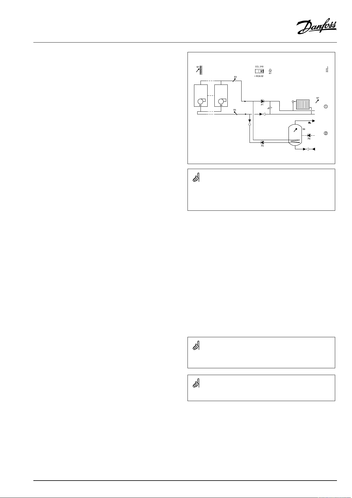
TypicalA375.2application:
*Pressurereliefvalve
Theshowndiagramisafundamentalandsimplifiedexampleanddoes
notcontainallcomponentsthatarenecessaryinasystem.
AllnamedcomponentsareconnectedtotheECLComfortcontroller.
Listofcomponents:
ECL310
ECA32
S1
S3
ElectroniccontrollerECLComfort310
Internalextensionmodulewithrelayoutputs
Outdoortemperaturesensor
(mandatory)Commonboilertemperaturesensor
S5Returntemperaturesensor
S6
S7
(S10)
P1
DHWtanktemperaturesensor
Roomtemperaturesensor/ECA30
(Externaltemperaturecontrol,notillustrated)
Circulationpump,heating
B1–B8Burner1...8
P3
A1
DHWheatingpump
Alarm
18|©Danfoss|2021.04
Thecontrollerispre-programmedwithfactorysettingsthatareshown
intherelevantchaptersofthisguide.
AQ042286456873en-010501
Page 19
OperatingGuideECLComfort210/296/310,applicationA275/A375
TheapplicationA375.3isveryflexible.Thesearethebasic
principles:
TheapplicationsA375.1/A375.2/A375.3canON/OFFcontrolup
to8burnersteps.
InapplicationA375.3thefirst2burnerstepsarecontrolledby
relaysintheECL310.Thenext,max.4burnersteps,arecontrolled
byrelaysintheextensionmoduleECA32(placedinthebasepartof
theECL310).Thelast,max.2burnerstepsarecontrolledbytriacs
intheECL310.Auxillaryrelaysmustbeconnectedtothetriacs.
Heating(circuit1):
Typically,thecommonboilertemperatureisadjustedaccordingto
yourrequirements.TheboilertemperaturesensorS3isthemost
importantsensor.Itmustbeplacedcorrectlyinordertomeasure
thecommonboilertemperature.Thedesiredboilertemperature
atS3iscalculatedintheECLcontroller,basedontheoutdoor
temperature(S1)andthedesiredroomtemperature.Thelowerthe
outdoortemperature,thehigherthedesiredboilertemperature.
Theboilertemperatureisalsotheflowtemperatureinthedirect
connectedheatingcircuit.
Bymeansofaweekschedule(upto3‘Comfort’periods/day),the
heatingcircuitcanbein‘Comfort’or‘Saving’mode(twodifferent
temperaturevaluesforthedesiredroomtemperature).In'Saving'
modea'Totalstop'functioncanbeselectedinordertoswitchOFF
theheating.
ThefirstburnerstepisswitchedONwhenthecommonboiler
temperatureislowerthanthedesiredboilertemperature.The
controllerobservesthecommonboilertemperatureandswitches
ONthenextburnerstepifthecommonboilertemperaturedoes
notincreasesatisfactorily.TheswitchingOFFprocedureofburner
stepsisviceversa.AswitchingdifferencedeterminestheON/OFF
control.
Theburnerscanbecontrolledin:
•fixedsequence(example:Always1-2-3-4-5)or
•automaticrotatingsequence(example:Firstperiod:1-2-3-4-5,
secondperiod:2-3-4-5-1,thirdperiod:3-4-5-1-2andsoon)
•semi-automaticrotatingsequence(example:Firstperiod:1,
2-3-4-5,secondperiod:1,3-4-5-2,thirdperiod:1,4-5-2-3and
soon)
Furthermore,theboilerprotectionfunctionwillswitchONthe
circulationpumpwhentheboilertemperaturegetsabovea
minimumvalue.AminimumON-timecanbesetfortheburnerin
ordertoincreasetheboiler'sefficiency.
Thereturntemperature(S5)totheboilershouldnotbetoo
high(condensingboiler)ortoolow(oilorgasfiredboiler).Ifso,
thedesiredboilertemperaturecanbedecreasedorincreased.
Furthermore,thereturntemperaturelimitationcanbedependent
ontheoutdoortemperature.Typically,thelowertheoutdoor
temperature,thehighertheacceptedreturntemperature.
TypicalA375.3application:
*Pressurereliefvalve
Theshowndiagramisafundamentalandsimplifiedexampleanddoes
notcontainallcomponentsthatarenecessaryinasystem.
AllnamedcomponentsareconnectedtotheECLComfortcontroller.
Listofcomponents:
ECL310
ECA32
S1
ElectroniccontrollerECLComfort310
Internalextensionmodulewithrelayoutputs
Outdoortemperaturesensor
S2Returntemperaturesensor,circuit2
S3
S4
(mandatory)Commonboilertemperaturesensor,circuit1
Flowtemperaturesensor,circuit2
S5Returntemperaturesensor,circuit1
S7
S8
(S10)
M2
P1
Roomtemperaturesensor/ECA30,circuit1
Roomtemperaturesensor/ECA30,circuit2
(Externaltemperaturecontrol,notillustrated)
Motorizedcontrolvalve,circuit2
Circulationpump,circuit1
B1–B8Burner1...8
P3
A1
DHWheatingpump,circuit3
Alarm
Ifthemeasuredroomtemperature(S7orRemotecontrolunitECA
30)doesnotequalthedesiredroomtemperature,thedesired
boilertemperaturecanbeadjusted.
Thecirculationpump(P1)isONatheatdemandoratfrost
protection.
TheheatingcanbeswitchedOFFwhentheoutdoortemperatureis
higherthanasetvalue.
Thedesiredcommonboilertemperaturecan,viaS10,becontrolled
bymeansofanexternalvoltageintherange0-10volt.
AQ042286456873en-010501
Thecontrollerispre-programmedwithfactorysettingsthatareshown
intherelevantchaptersofthisguide.
Boilersequencerotation/shifttakesplaceatmidnight.
©Danfoss|2021.04|19
Page 20
OperatingGuideECLComfort210/296/310,applicationA275/A375
A375.3,basicprinciples,continued:
Heating(circuit2):
Typically,theflowtemperatureisadjustedaccordingtoyour
requirements.TheflowtemperaturesensorS4isthemost
importantsensor.ThedesiredflowtemperatureatS4iscalculated
intheECLcontroller,basedontheoutdoortemperature(S1).
Thelowertheoutdoortemperature,thehigherthedesiredflow
temperature.
Bymeansofaweekschedule(upto3‘Comfort’periods/day),the
heatingcircuitcanbein‘Comfort’or‘Saving’mode(twodifferent
temperaturevaluesforthedesiredroomtemperature).In'Saving'
modea'Totalstop'functioncanbeselectedinordertoswitchOFF
theheating.
ThemotorizedcontrolvalveM2isopenedgraduallywhentheflow
temperature,S4,islowerthanthedesiredflowtemperatureand
viceversa.
ThedesiredflowtemperatureatS4willtypicallydeterminethe
desiredboilertemperature(S3).
Thereturntemperature(S2)canbelimited.Ifso,thedesiredflow
temperatureatS4canbedecreasedorincreased.
Furthermore,thereturntemperaturelimitationcanbedependent
ontheoutdoortemperature.Typically,thelowertheoutdoor
temperature,thehighertheacceptedreturntemperature.
Ifthemeasuredroomtemperature(measuredbyS8ortheremote
controlunitECA30)doesnotequalthedesiredroomtemperature,
thedesiredflowtemperaturecanbeadjusted.
Thecirculationpump(P4)isONatheatdemandoratfrost
protection.
TheheatingcanbeswitchedOFFwhentheoutdoortemperatureis
higherthanaselectablevalueoraDHWheatingpriorityispresent.
TypicalA375.3application:
*Pressurereliefvalve
Theshowndiagramisafundamentalandsimplifiedexampleanddoes
notcontainallcomponentsthatarenecessaryinasystem.
AllnamedcomponentsareconnectedtotheECLComfortcontroller.
Listofcomponents:
ECL310
ECA32
S1
ElectroniccontrollerECLComfort310
Internalextensionmodulewithrelayoutputs
Outdoortemperaturesensor
S2Returntemperaturesensor,circuit2
S3
S4
(mandatory)Commonboilertemperaturesensor,circuit1
Flowtemperaturesensor,circuit2
S5Returntemperaturesensor,circuit1
S7
S8
(S10)
M2
P1
Roomtemperaturesensor/ECA30,circuit1
Roomtemperaturesensor/ECA30,circuit2
(Externaltemperaturecontrol,notillustrated)
Motorizedcontrolvalve,circuit2
Circulationpump,circuit1
B1–B8Burner1...8
P3
A1
DHWheatingpump,circuit3
Alarm
20|©Danfoss|2021.04
Thecontrollerispre-programmedwithfactorysettingsthatareshown
intherelevantchaptersofthisguide.
AQ042286456873en-010501
Page 21
OperatingGuideECLComfort210/296/310,applicationA275/A375
A375.3,basicprinciples,continued:
DHW(circuit3):
Bymeansofaweekschedule(upto3‘Comfort’periods/day),the
DHWcircuitcanbein‘Comfort’or‘Saving’mode(twodifferent
temperaturevaluesfordesiredDHWtemperature).
IfthemeasuredDHWtemperature(S6)islowerthanthedesired
DHWtemperature,theDHWheatingprocedurestarts:
•ThecirculationpumpP1intheheatingcircuitisswitchedOFF
•TheDHWheatingpumpP3isswitchedON
•ThedesiredboilertemperatureatS3isincreased.
Thedesiredboilertemperatureistypically10-15degreeshigher
thanthedesiredDHWtemperature.
WhenthemeasuredDHWtemperature(S6)getshigherthanthe
desiredDHWtemperature,theDHWheatingpump(P3)isswitched
OFF.StartandstopdifferencesdeterminetheON/OFFcontrol.A
post-runtimecanbeset.
Ananti-bacteriafunctionisavailableforactivationonselected
daysoftheweek.
TheDHWheatingcanhavepriority,i.e.pumpP3isONandpump
P1isOFF.Iftheapplicationhasachangeovervalve(priorityvalve)
fortheDHWheating,thecirculationpumpP1isstillONduring
DHWheating.
TypicalA375.3application:
*Pressurereliefvalve
Theshowndiagramisafundamentalandsimplifiedexampleanddoes
notcontainallcomponentsthatarenecessaryinasystem.
AllnamedcomponentsareconnectedtotheECLComfortcontroller.
Listofcomponents:
ECL310
ECA32
S1
ElectroniccontrollerECLComfort310
Internalextensionmodulewithrelayoutputs
Outdoortemperaturesensor
S2Returntemperaturesensor,circuit2
S3
S4
(mandatory)Commonboilertemperaturesensor,circuit1
Flowtemperaturesensor,circuit2
S5Returntemperaturesensor,circuit1
S7
S8
(S10)
M2
P1
Roomtemperaturesensor/ECA30,circuit1
Roomtemperaturesensor/ECA30,circuit2
(Externaltemperaturecontrol,notillustrated)
Motorizedcontrolvalve,circuit2
Circulationpump,circuit1
B1–B8Burner1...8
P3
A1
DHWheatingpump,circuit3
Alarm
Thecontrollerispre-programmedwithfactorysettingsthatareshown
intherelevantchaptersofthisguide.
AQ042286456873en-010501
©Danfoss|2021.04|21
Page 22
OperatingGuideECLComfort210/296/310,applicationA275/A375
TheapplicationA375.4isveryflexible.Thesearethebasic
principles:
Heating(circuit1):
Typically,theboilertemperatureisadjustedaccordingtoyour
requirements.TheboilertemperaturesensorS3isthemost
importantsensor.Itmustbeplacedcorrectlytomeasuretheboiler
temperature.ThedesiredboilertemperatureatS3iscalculatedin
theECLcontroller,basedontheoutdoortemperature(S1)andthe
desiredroomtemperature.Thelowertheoutdoortemperature,
thehigherthedesiredboilertemperature.Theboilertemperature
isalsotheflowtemperatureinthedirectconnectedheatingcircuit.
Bymeansofaweekschedule(upto3‘Comfort’periods/day),the
heatingcircuitcanbein‘Comfort’or‘Saving’mode(twodifferent
temperaturevaluesforthedesiredroomtemperature).In'Saving'
modea'Totalstop'functioncanbeselectedtoswitchOFFthe
heating.
Theburneris,viarelayoutput2,switchedONwhentheboiler
temperatureislowerthanthedesiredboilertemperatureand
switchedOFFwhentheboilertemperatureishigherthanthe
desiredboilertemperature.Aswitchingdifferencedeterminesthe
ON/OFFcontrol.
Advancedboilercontrol:
1.A0-10VoltsignalfromtheinternalmoduleECA32canbe
appliedtotheboilerforsettingthedesiredboilertemperature.
2.A3-pointsignal,viaM3,canbeappliedtotheboilerforsetting
thedesiredboilertemperature.Itisrecommendedtoseparate
galvanicallytheECL'sM3outputfromtheboiler's3-pointinput.
Typically,thiscanbedonebymeansofSolid-Staterelays.
SeetheInstallationGuideforconnections.
TheboilerprotectionfunctionwillonlyswitchONthecirculation
pumpiftheboilertemperaturegetsaboveaminimum
temperature.AminimumON-timecanbesetfortheburnerto
increasetheboiler'sefficiency.
Thereturntemperature(S5)totheboilershouldnotbetoohigh
(condensingboiler)ortoolow(oilorgasfiredboiler).Ifso,the
desiredboilertemperaturecanbedecreasedorincreased.
Furthermore,thereturntemperaturelimitationcanbedependent
ontheoutdoortemperature.Typically,thelowertheoutdoor
temperature,thehighertheacceptedreturntemperature.
Ifthemeasuredroomtemperature(measuredbyS7ortheremote
controlunitECA30)doesnotequalthedesiredroomtemperature,
thedesiredboilertemperaturecanbeadjusted.
Thecirculationpump(P1)isONatheatdemandoratfrost
protection.
TypicalA375.4application:
*Pressurereliefvalve
Theshowndiagramisafundamentalandsimplifiedexampleanddoes
notcontainallcomponentsthatarenecessaryinasystem.
AllnamedcomponentsareconnectedtotheECLComfortcontroller.
Listofcomponents:
ECL310
ECA32
S1
S3
ElectroniccontrollerECLComfort310
Internalextensionmodulewithanalogoutputs
Outdoortemperaturesensor
(mandatory)Boilertemperaturesensor
S5Returntemperaturesensor
S7
Roomtemperaturesensor/ECA30
S9Pressuresensor
P1
B1
V1
M3
A1
Circulationpump
Burner,ON/OFFcontrol
Burner,0-10Vtemperaturecontrol
(notillustrated)3-pointcontrolofboilertemperature
Alarm
Thecontrollerispre-programmedwithfactorysettingsthatareshown
intherelevantchaptersofthisguide.
TheheatingcanbeswitchedOFFiftheoutdoortemperaturegets
higherthanasetvalue.
A375.4canalsoruntheinstallationslikeA275.1,ex.aandex.b.
ThedifferencebetweenA375.4andA275.1is:
•A375.4hasadvancedboilercontrol
•A375.4canmeasurepressureviatransmitterandgenerate
alarm
22|©Danfoss|2021.04
AQ042286456873en-010501
Page 23
OperatingGuideECLComfort210/296/310,applicationA275/A375
TheapplicationA375.5isveryflexible.Thesearethebasic
principles:
Heating(circuit1):
Typically,theboilertemperatureisadjustedaccordingtoyour
requirements.TheboilertemperaturesensorS3isthemost
importantsensor.Itmustbeplacedcorrectlytomeasuretheboiler
temperature.ThedesiredboilertemperatureatS3iscalculatedin
theECLcontroller,basedontheoutdoortemperature(S1)andthe
desiredroomtemperature.Thelowertheoutdoortemperature,
thehigherthedesiredboilertemperature.Theboilertemperature
isalsotheflowtemperatureinthedirectconnectedheatingcircuit.
Bymeansofaweekschedule(upto3‘Comfort’periods/day),the
heatingcircuitcanbein‘Comfort’or‘Saving’mode(twodifferent
temperaturevaluesforthedesiredroomtemperature).In'Saving'
modea'Totalstop'functioncanbeselectedtoswitchOFFthe
heating.
Theburneris,viarelayoutput2,switchedONwhentheboiler
temperatureislowerthanthedesiredboilertemperatureand
switchedOFFwhentheboilertemperatureishigherthanthe
desiredboilertemperature.Aswitchingdifferencedeterminesthe
ON/OFFcontrol.
Advancedboilercontrol:
1.A0-10VoltsignalfromtheinternalmoduleECA32canbe
appliedtotheboilerforsettingthedesiredboilertemperature.
2.A3-pointsignal,viaM3,canbeappliedtotheboilerforsetting
thedesiredboilertemperature.Itisrecommendedtoseparate
galvanicallytheECL'sM3outputfromtheboiler's3-pointinput.
Typically,thiscanbedonebymeansofSolid-Staterelays.
SeetheInstallationGuideforconnections.
TheboilerprotectionfunctionwillonlyswitchONthecirculation
pumpiftheboilertemperaturegetsaboveaminimum
temperature.AminimumON-timecanbesetfortheburnerto
increasetheboiler'sefficiency.
Thereturntemperature(S5)totheboilershouldnotbetoohigh
(condensingboiler)ortoolow(oilorgasfiredboiler).Ifso,the
desiredboilertemperaturecanbedecreasedorincreased.
Furthermore,thereturntemperaturelimitationcanbedependent
ontheoutdoortemperature.Typically,thelowertheoutdoor
temperature,thehighertheacceptedreturntemperature.
Ifthemeasuredroomtemperature(measuredbyS7ortheremote
controlunitECA30)doesnotequalthedesiredroomtemperature,
thedesiredboilertemperaturecanbeadjusted.
Thecirculationpump(P1)isONatheatdemandoratfrost
protection.
TheheatingcanbeswitchedOFFiftheoutdoortemperaturegets
higherthanasetvalue.
TypicalA375.5application:
*Pressurereliefvalve
Theshowndiagramisafundamentalandsimplifiedexampleanddoes
notcontainallcomponentsthatarenecessaryinasystem.
AllnamedcomponentsareconnectedtotheECLComfortcontroller.
Listofcomponents:
ECL310
ECA32
S1
ElectroniccontrollerECLComfort310
Internalextensionmodulewithanalogoutputs
Outdoortemperaturesensor
S2Returntemperaturesensor,circuit2
S3
S4
(mandatory)Boilertemperaturesensor
Flowtemperaturesensor,circuit2
S5Returntemperaturesensor
S6
S7
S8
DHWtanktemperaturesensor
Roomtemperaturesensor/ECA30
Roomtemperaturesensor/ECA30,circuit2
S9Pressuresensor
P1
P3
P4
P5
B1
V1
M2
M3
A1
Circulationpump
DHWheatingpump
Circulationpump,circuit2
DHWcirculationpump
Burner,ON/OFFcontrol
Burner,0-10Vtemperaturecontrol
Motorizedcontrolvalve,circuit2
(notillustrated)3-pointcontrolofboilertemperature
Alarm
Thecontrollerispre-programmedwithfactorysettingsthatareshown
intherelevantchaptersofthisguide.
AQ042286456873en-010501
©Danfoss|2021.04|23
Page 24
OperatingGuideECLComfort210/296/310,applicationA275/A375
A375.5,basicprinciples,continued:
Heating(circuit2):
Typically,theflowtemperatureisadjustedaccordingtoyour
requirements.TheflowtemperaturesensorS4isthemost
importantsensor.ThedesiredflowtemperatureatS4iscalculated
intheECLcontroller,basedontheoutdoortemperature(S1)and
thedesiredroomtemperature.Thelowertheoutdoortemperature,
thehigherthedesiredflowtemperature.
Bymeansofaweekschedule(upto3‘Comfort’periods/day),the
heatingcircuitcanbein‘Comfort’or‘Saving’mode(twodifferent
temperaturevaluesforthedesiredroomtemperature).In'Saving'
modea'Totalstop'functioncanbeselectedtoswitchOFFthe
heating.
ThemotorizedcontrolvalveM2isopenedgraduallywhentheflow
temperature,S4,islowerthanthedesiredflowtemperatureand
viceversa.
ThedesiredflowtemperatureatS4willtypicallydeterminethe
desiredboilertemperature(S3).
Thereturntemperature(S2)canbelimited.Ifso,thedesiredflow
temperatureatS4canbedecreasedorincreased.
Furthermore,thereturntemperaturelimitationcanbedependent
ontheoutdoortemperature.Typically,thelowertheoutdoor
temperature,thehighertheacceptedreturntemperature.
TypicalA375.5application:
*Pressurereliefvalve
Theshowndiagramisafundamentalandsimplifiedexampleanddoes
notcontainallcomponentsthatarenecessaryinasystem.
AllnamedcomponentsareconnectedtotheECLComfortcontroller.
Ifthemeasuredroomtemperature(measuredbyS8ortheremote
controlunitECA30)doesnotequalthedesiredroomtemperature,
thedesiredflowtemperaturecanbeadjusted.
Thecirculationpump(P4)isONatheatdemandoratfrost
protection.
TheheatingcanbeswitchedOFFwhentheoutdoortemperatureis
higherthanaselectablevalueoraDHWheatingpriorityispresent.
Listofcomponents:
ECL310
ECA32
S1
ElectroniccontrollerECLComfort310
Internalextensionmodulewithanalogoutputs
Outdoortemperaturesensor
S2Returntemperaturesensor,circuit2
S3
S4
(mandatory)Boilertemperaturesensor
Flowtemperaturesensor,circuit2
S5Returntemperaturesensor
S6
S7
S8
DHWtanktemperaturesensor
Roomtemperaturesensor/ECA30
Roomtemperaturesensor/ECA30,circuit2
S9Pressuresensor
P1
P3
P4
P5
B1
V1
M2
M3
A1
Circulationpump
DHWheatingpump
Circulationpump,circuit2
DHWcirculationpump
Burner,ON/OFFcontrol
Burner,0-10Vtemperaturecontrol
Motorizedcontrolvalve,circuit2
(notillustrated)3-pointcontrolofboilertemperature
Alarm
24|©Danfoss|2021.04
Thecontrollerispre-programmedwithfactorysettingsthatareshown
intherelevantchaptersofthisguide.
AQ042286456873en-010501
Page 25

OperatingGuideECLComfort210/296/310,applicationA275/A375
A375.5,basicprinciples,continued:
DHW(circuit3):
Bymeansofaweekschedule(upto3‘Comfort’periods/day),the
DHWcircuitcanbein‘Comfort’or‘Saving’mode(twodifferent
temperaturevaluesfordesiredDHWtemperature).
IfthemeasuredDHWtemperature(S6)islowerthanthedesired
DHWtemperature,theDHWheatingprocedurestarts:
•ThecirculationpumpP1intheheatingcircuitisswitchedOFF
•TheDHWheatingpumpP3isswitchedON
•ThedesiredboilertemperatureatS3isincreased.
Thedesiredboilertemperatureistypically10-15degreeshigher
thanthedesiredDHWtemperature.
WhenthemeasuredDHWtemperature(S6)getshigherthanthe
desiredDHWtemperature,theDHWheatingpump(P3)isswitched
OFF.StartandstopdifferencesdeterminetheON/OFFcontrol.A
post-runtimecanbeset.
Ananti-bacteriafunctionisavailableforactivationontheselected
daysoftheweek.
TheDHWheatinghaspriority,i.e.pumpP3isONandpumpP1is
OFF.Iftheapplicationhasachangeovervalve(priorityvalve)for
theDHWheating,thecirculationpumpP1isstillONduringDHW
heating.
TypicalA375.5application:
*Pressurereliefvalve
Theshowndiagramisafundamentalandsimplifiedexampleanddoes
notcontainallcomponentsthatarenecessaryinasystem.
AllnamedcomponentsareconnectedtotheECLComfortcontroller.
A375.5canalsoruntheinstallationslikeA275.3,ex.a.-A275.3,
ex.g.
ThedifferenciesbetweenA375.5andA275.3are:
•A375.5hasadvancedboilercontrol
•A375.5hasalarmoutput(A1)
•A375.4canmeasurepressureviatransmitterandgenerate
alarm
Listofcomponents:
ECL310
ECA32
S1
ElectroniccontrollerECLComfort310
Internalextensionmodulewithanalogoutputs
Outdoortemperaturesensor
S2Returntemperaturesensor,circuit2
S3
S4
(mandatory)Boilertemperaturesensor
Flowtemperaturesensor,circuit2
S5Returntemperaturesensor
S6
S7
S8
DHWtanktemperaturesensor
Roomtemperaturesensor/ECA30
Roomtemperaturesensor/ECA30,circuit2
S9Pressuresensor
P1
P3
P4
P5
B1
V1
M2
M3
A1
Circulationpump
DHWheatingpump
Circulationpump,circuit2
DHWcirculationpump
Burner,ON/OFFcontrol
Burner,0-10Vtemperaturecontrol
Motorizedcontrolvalve,circuit2
(notillustrated)3-pointcontrolofboilertemperature
Alarm
Thecontrollerispre-programmedwithfactorysettingsthatareshown
intherelevantchaptersofthisguide.
AQ042286456873en-010501
©Danfoss|2021.04|25
Page 26

OperatingGuideECLComfort210/296/310,applicationA275/A375
ApplicationA375ingeneral:
UptotwoRemoteControlUnits,ECA30/31,canbeconnectedto
oneECLcontrollertocontroltheECLcontrollerremotely.
Exerciseofcirculationpumpsandcontrolvalveinperiodswithout
heatingdemandcanbearranged.
AdditionalECLComfortcontrollerscanbeconnectedviatheECL
485bustoutilizecommonoutdoortemperaturesignal,timeand
datesignals.
SeveralECLcontrollers,internallyconnectedviaECL485bus,work
inMaster/Slaveconnection.InaMaster/Slavesystemmaximum
2ECA30/31canbepresent.
Unusedinput(fromS7andup)can,bymeansofanoverride
switch,beusedtooverridethescheduletoafixed'Comfort'or
'Saving'mode.
Modbuscommunication(ECL296andECL310)toaSCADAsystem
canbeestablished.
ECLPortal,Internetbasedconnection,allowsECL296,310and
310Btobemonitoredandcontrolledremotelyviastandard
Internetbrowsers(forexampleInternetExplorer,GoogleChrome
andSafari).
Heat-meters:
Upto5heat-meterscanbeconnectedtotheM-busterminals(ECL
296/310).
DatacanbetransferredtotheSCADAsystemviaModbusandTCP/
IPtotheECLPortal.
ModbuscommunicationtoaSCADAsystemcanbeestablished.
TheM-busdata(ECLComfort296/310)canfurthermorebe
transferredtotheModbuscommunication.
Alarm,A375:
AlarmA1(relayR6)andthealarmsymbol(
•ifatemperaturesensororitsconnectiondisconnects/
shortcircuits.
Alarm,A375.3andA375.5:
AlarmA1(relayR6)andthealarmsymbol(
•iftheactualflowtemperatureatS4(heatingcircuit2),differs
fromthedesiredflowtemperature.
Alarm,A375.4,A375.5:
AlarmA1(relayR6)andthealarmsymbol(
•ifthepressure,measuredbyS9,getshigherorlowerthanset
alarmvalues.
)canbeactivated:
)canbeactivated:
)canbeactivated:
26|©Danfoss|2021.04
AQ042286456873en-010501
Page 27

OperatingGuideECLComfort210/296/310,applicationA275/A375
ApplicationA375ingeneral,continued:
Offsetadjustment
Ameasuredtemperaturecanbeoffsetadjusted,ifneeded.
(Navigation:MENU>Commoncontroller>System>Sensoroffset)
Inputconfiguration
Inputs(asfromS7andup),whicharenotpartoftheapplication
canbeconfiguredtobePt1000,0-10Volt,frequency(pulse
counter)ordigitalinput.ThisfeaturemakesitpossibleinECL296/
310tocommunicateextrasignals,suchastemperatures,pressures,
ON/OFFconditions,viaModbusandECLPortal.
TheconfigurationisdonebymeansoftheECLTool(freesoftware
fordownload)ordirectlyinadedicatedmenuintheECLPortalor
theconnectionforModbus(BMS/SCADA).
Applicationupload
Theapplicationuploadprocedureisthefollowingafterhaving
powereduptheECLComfortcontroller:
1.Inserttheapplicationkey
2.Selectlanguage,*1,*2
3.Selectsubtype(theInstallationGuideshowssubtypes)
4.SetTimeandDate
TheECLComfortcontrollerinstallstheapplication,initializesand
restarts.Outputrelaysareactivated/de-activated(click-sounds
fromthiscanbeheard).Thisalsomeansthat,forexample,
circulationpumpscanbeswitchedONandOFFshortly.
*1:Seealsosection"InsertingtheECLApplicationKey" .
*2:(ECLComfort310,24Volt)Iflanguagecannotbeselected,the
powersupplyisnota.c.(alternatingcurrent).
Commissioning
WhentheselectedapplicationhasbeenuploadedtheECLComfort
controllerstartsinManualmode.Thiscanbeusedtoverifycorrect
connectionsof,forexample,temperature,pressureandflow
sensors.Alsoverifyingthecontrolledcomponents(valveactuators,
pumps,burneretc.)forcorrectfunctionalitycanbedone.
Theapplicationkeyisdeliveredwithfactorysettings.
Dependingonsystemtype,itmightbenecessarytochangesome
factorysettingsindividuallyforoptimizingthefunctionality.
Theapplicationkeymustbeinsertedforchangingsettings.
Power-down/power-up
WhenthepowersupplytotheECLComfortcontrolleris
disconnected(power-down),theoutputrelaysgotode-activated
position.
Thismeansthat,forexample,circulationpumpsandburnercanbe
switchedON.
SeetheelectricalconnectiondiagramsintheInstallationGuide.
Allrelaycontactsareshowninde-activatedsituation.Somerelay
contactsareclosed,somerelaycontactsareopen.
WhenthepowersupplytotheECLComfortcontrolleris
re-established(power-up),theoutputrelaysareactivated/
de-activated(click-soundsfromthiscanbeheard).Thisalsomeans
that,forexample,circulationpumpsandburnercanbeswitched
ONandOFFshortly.
ImportantforA375.3andA375.5:
•Setthecorrectrunningtime"Mrun"oftheMotorizedControl
ValveM2.(Circuit2>MENU>Settings>Controlparameters
>Mrun).
AQ042286456873en-010501
©Danfoss|2021.04|27
Page 28

OperatingGuideECLComfort210/296/310,applicationA275/A375
Thecontrollerispre-programmedwithfactorysettingsthatareshown
inthe‘ParameterIDoverview’appendix.
28|©Danfoss|2021.04
AQ042286456873en-010501
Page 29
OperatingGuideECLComfort210/296/310,applicationA275/A375
2.2Identifyingthesystemtype
Sketchyourapplication
TheECLComfortcontrollerseriesisdesignedforawiderange
ofheating,domestichot-water(DHW)andcoolingsystemswith
differentconfigurationsandcapacities.Ifyoursystemdiffers
fromthediagramsshownhere,youmaywanttomakeasketch
ofthesystemabouttobeinstalled.Thismakesiteasiertouse
theOperatingGuide,whichwillguideyoustep-by-stepfrom
installationtofinaladjustmentsbeforetheend-usertakesover.
TheECLComfortcontrollerisauniversalcontrollerthatcanbe
usedforvarioussystems.Basedontheshownstandardsystems,
itispossibletoconfigureadditionalsystems.Inthischapteryou
findthemostfrequentlyusedsystems.Ifyoursystemisnotquite
asshownbelow,findthediagramwhichhasthebestresemblance
withyoursystemandmakeyourowncombinations.
SeetheInstallationGuide(deliveredwiththeapplicationkey)for
applicationtypes/sub-types.
Thecirculationpump(s)inheatingcircuit(s)canbeplacedintheflow
aswellasthereturn.Placethepumpaccordingtothemanufacturer’s
specification.
AQ042286456873en-010501
©Danfoss|2021.04|29
Page 30

OperatingGuideECLComfort210/296/310,applicationA275/A375
A275applications:
SeetheInstallationGuide(deliveredwiththeapplicationkey)forapplicationexamplesandelectricalconnections.
A275.1,examplea
BoilerON/OFFcontrolforaheatingcircuit.
Thecomponentmarkedwith*isapressurereliefvalve.
A275.1,exampleb
BoilerON/OFFcontrolforaheatingcircuit.Theboilercircuitisequippedwithalowlossheader.
Thecomponentmarkedwith*isapressurereliefvalve.
A275.2,examplea
BoilerON/OFFcontrolforaheatingandaDHWcircuit.OptionalDHWpriority.
Thecomponentmarkedwith*isapressurereliefvalve.
AtDHWheatingP3isswitchedONandthedesiredboilertemperatureliesanumberofdegreesabovethedesiredDHWtemperature.
P1isswitchedOFF.
SpecialsettingsfortypeA275.2,examplea:
Navigation:
DHWcircuit(circuit2)
DHWheatingismanagedbypumpP3:
MENU\Settings\Application:'Ch.-o.valve/P'
ThedesiredDHWheatingtemperaturemustinfluencethedesiredboilertemperature:
MENU\Settings\Application:‘Tank,sec./prim.'
Pleasenote:
If'Ch.-o.valve/P'in12051issettoOFF,P3willbeswitchedonatDHWheating.Thedesiredboilertemperaturewillstillliea
numberofdegreesabovethedesiredDHWtemperatureandP1willremainswitchedON.
A275.2,exampleb
BoilerON/OFFcontrolforaheatingandaDHWcircuit.DHWpriority.
Thecomponentmarkedwith*isapressurereliefvalve.
AtDHWheatingP3(changeovervalve)isactivatedandthedesiredboilertemperatureliesanumberofdegreesabovethedesiredDHW
temperature.
P1iscontinuouslyswitchedON.
SpecialsettingsfortypeA275.2,exampleb:
IDno.:
12051
12053
Recommendedsetting:
ON
OFF
Navigation:
DHWcircuit(circuit2)
DHWheatingismanagedbychangeovervalveP3/M1:
MENU\Settings\Application:'Ch.-o.valve/P'
ThedesiredDHWheatingtemperaturemustinfluencethedesiredboilertemperature:
MENU\Settings\Application:‘Tank,sec./prim.'
30|©Danfoss|2021.04
IDno.:
12051
12053
Recommendedsetting:
OFF
OFF
AQ042286456873en-010501
Page 31

OperatingGuideECLComfort210/296/310,applicationA275/A375
SeetheInstallationGuide(deliveredwiththeapplicationkey)forapplicationexamplesandelectricalconnections.
A275.2,examplec
BoilerON/OFFcontrolforaheatingandaDHWcircuit.OptionalDHWpriority.Theboilercircuitisequippedwithalowlossheader.
Thecomponentmarkedwith*isapressurereliefvalve.
Thepumpintheboilercircuitisnotcontrolled.
AtDHWheatingP3isswitchedONandthedesiredboilertemperatureliesanumberofdegreesabovethedesiredDHWtemperature.
P1isswitchedOFF.
SpecialsettingsfortypeA275.2,examplec:
Navigation:IDno.:
DHWcircuit(circuit2)
DHWheatingismanagedbypumpP3:
MENU\Settings\Application:'Ch.-o.valve/P'
ThedesiredDHWheatingtemperaturemustinfluencethedesiredboilertemperature:
MENU\Settings\Application:‘Tank,sec./prim.'
Pleasenote:
If'Ch.-o.valve/P'in12051issettoOFF,P3willbeswitchedonatDHWheating.Thedesiredboilertemperaturewillstillliea
numberofdegreesabovethedesiredDHWtemperatureandP1remainswitchedON.
A275.2,exampled
BoilerON/OFFcontrolforaheatingandaDHWcircuit.DHWpriority.Theboilercircuitisequippedwithalowlossheader.
Thecomponentmarkedwith*isapressurereliefvalve.
Thepumpintheboilercircuitisnotcontrolled.
AtDHWheatingP3(changeovervalve)isactivatedandthedesiredboilertemperatureliesanumberofdegreesabovethedesiredDHW
temperature.
P1isswitchedON.
SpecialsettingsfortypeA275.2,exampled:
12051
12053
Recommendedsetting:
ON
OFF
Navigation:
DHWcircuit(circuit2)
DHWheatingismanagedbychangeovervalveP3/M1:
MENU\Settings\Application:'Ch.-o.valve/P'
ThedesiredDHWheatingtemperaturemustinfluencethedesiredboilertemperature:
MENU\Settings\Application:‘Tank,sec./prim.'
AQ042286456873en-010501
IDno.:
12051
12053
Recommendedsetting:
OFF
OFF
©Danfoss|2021.04|31
Page 32

OperatingGuideECLComfort210/296/310,applicationA275/A375
SeetheInstallationGuide(deliveredwiththeapplicationkey)forapplicationexamplesandelectricalconnections.
A275.3,examplea
BoilerON/OFFcontrolforadirectheatingcircuit(1),amixingcircuit(2)andaDHWcircuit(3).OptionalDHWpriority.
Thecomponentmarkedwith*isapressurereliefvalve.
Heatingcircuit2canalternativelybeafloorheatingcircuit.
AtDHWheatingP3isswitchedONandthedesiredboilertemperatureliesanumberofdegreesabovethedesiredDHWtemperature.
P1isswitchedOFF .Heatingcircuit2canbeclosedduringDHWheating.
SpecialsettingsfortypeA275.3,examplea:
Navigation:IDno.:
Heatingcircuit(circuit1)
Circuit1mustbeabletoreceiveaheatdemand(desiredflowtemperature)fromcircuit2:
MENU\Settings\Application:'Demandoffset'
**Thisvalueisaddedtotheheatdemandvaluefromcircuit2
Heatingcircuit(circuit2)
Circuit2mustbeabletosendaheatdemand(desiredflowtemperature)tocircuit1:
MENU\Settings\Application:'SenddesiredT'
Circuit2canbeclosedduringtheDHWheatingprocess:
MENU\Settings\Application:‘DHWpriority'
***Set'OFF'whennottobeclosed,set'ON'whentobeclosed
DHWcircuit(circuit3)
DHWheatingismanagedbypumpP3:
MENU\Settings\Application:'Ch.-o.valve/P'
ThedesiredDHWheatingtemperaturemustinfluencetheboilertemperature:
MENU\Settings\Application:‘Tank,sec./prim.'
11017
12500
12052
13051
13053
Recommendedsetting:
3K**
ON
***
ON
OFF
32|©Danfoss|2021.04
AQ042286456873en-010501
Page 33

OperatingGuideECLComfort210/296/310,applicationA275/A375
SeetheInstallationGuide(deliveredwiththeapplicationkey)forapplicationexamplesandelectricalconnections.
A275.3,exampleb
BoilerON/OFFcontrolforadirectheatingcircuit(1),amixingcircuit(2)andaDHWcircuit(3).PartlyDHWpriority.
Thecomponentmarkedwith*isapressurereliefvalve.
Heatingcircuit2canalternativelybeafloorheatingcircuit.
AtDHWheatingP3(changeovervalve)isactivatedandthedesiredboilertemperatureisanumberofdegreesabovethedesiredDHW
temperature.
P1iscontinuouslyswitchedON.
Heatingcircuit2canbeclosedduringDHWheating.
SpecialsettingsfortypeA275.3,exampleb:
Navigation:IDno.:
Heatingcircuit(circuit1)
Circuit1mustbeabletoreceiveaheatdemand(desiredflowtemperature)fromcircuit2:
MENU\Settings\Application:'Demandoffset'
**Thisvalueisaddedtotheheatdemandvaluefromcircuit2
Heatingcircuit(circuit2)
Circuit2mustbeabletosendaheatdemand(desiredflowtemperature)tocircuit1:
MENU\Settings\Application:'SenddesiredT'
Circuit2canbeclosedduringtheDHWheatingprocess:
MENU\Settings\Application:‘DHWpriority'
***Set'OFF'whennottobeclosed,set'ON'whentobeclosed
DHWcircuit(circuit3)
DHWheatingismanagedbychangeovervalveP3/M1:
MENU\Settings\Application:'Ch.-o.valve/P'
ThedesiredDHWheatingtemperaturemustinfluencetheboilertemperature:
MENU\Settings\Application:‘Tank,sec./prim.'
11017
12500
12052
13051
13053
Recommendedsetting:
3K**
ON
***
OFF
OFF
AQ042286456873en-010501
©Danfoss|2021.04|33
Page 34

OperatingGuideECLComfort210/296/310,applicationA275/A375
SeetheInstallationGuide(deliveredwiththeapplicationkey)forapplicationexamplesandelectricalconnections.
A275.3,examplec
BoilerON/OFFcontrolforadirectheatingcircuit(1),amixingcircuit(2)andaDHWcircuit(3).DHWpriority.
Thecomponentmarkedwith*isapressurereliefvalve.
Heatingcircuit2canalternativelybeafloorheatingcircuit.
AtDHWheating,P3(changeovervalve)isactivatedandthedesiredboilertemperatureisanumberofdegreesabovethedesiredDHW
temperature.
P1iscontinuouslyswitchedON.
Heatingcircuit2isclosedduringDHWheating.
SpecialsettingsfortypeA275.3,examplec:
Navigation:IDno.:
Heatingcircuit(circuit1)
Circuit1mustbeabletoreceiveaheatdemand(desiredflowtemperature)fromcircuit2:
MENU\Settings\Application:'Demandoffset'
**Thisvalueisaddedtotheheatdemandvaluefromcircuit2
Heatingcircuit(circuit2)
Circuit2mustbeabletosendaheatdemand(desiredflowtemperature)tocircuit1:
MENU\Settings\Application:'SenddesiredT'
Circuit2mustbeclosedduringtheDHWheatingprocess:
MENU\Settings\Application:‘DHWpriority'
DHWcircuit(circuit3)
DHWheatingismanagedbychangeovervalveP3/M1:
MENU\Settings\Application:'Ch.-o.valve/P'
ThedesiredDHWheatingtemperaturemustinfluencetheboilertemperature:
MENU\Settings\Application:‘Tank,sec./prim.'
11017
12500
12052
13051
13053
Recommendedsetting:
3K**
ON
ON
OFF
OFF
34|©Danfoss|2021.04
AQ042286456873en-010501
Page 35

OperatingGuideECLComfort210/296/310,applicationA275/A375
SeetheInstallationGuide(deliveredwiththeapplicationkey)forapplicationexamplesandelectricalconnections.
A275.3,exampled
BoilerON/OFFcontrolforadirectheatingcircuit(1),amixingcircuit(2)andaDHWcircuit(3).OptionalDHWpriority.Themixingcircuit
(2)iscontrolledbymeansofa4-portmixingvalve
Thecomponentmarkedwith*isapressurereliefvalve.
Heatingcircuit2canalternativelybeafloorheatingcircuit.
AtDHWheatingP3isswitchedONandthedesiredboilertemperatureisanumberofdegreesabovethedesiredDHWtemperature.
P1isswitchedOFF.
Heatingcircuit2canbeclosedduringDHWheating.
SpecialsettingsfortypeA275.3,exampled:
Navigation:IDno.:
Heatingcircuit(circuit1)
Circuit1mustbeabletoreceiveaheatdemand(desiredflowtemperature)fromcircuit2:
MENU\Settings\Application:'Demandoffset'
**Thisvalueisaddedtotheheatdemandvaluefromcircuit2
Heatingcircuit(circuit2)
Circuit2mustbeabletosendaheatdemand(desiredflowtemperature)tocircuit1:
MENU\Settings\Application:'SenddesiredT'
Circuit2canbeclosedduringtheDHWheatingprocess:
MENU\Settings\Application:‘DHWpriority'
***Set'OFF'whennottobeclosed,set'ON'whentobeclosed
DHWcircuit(circuit3)
DHWheatingismanagedbypumpP3:
MENU\Settings\Application:'Ch.-o.valve/P'
ThedesiredDHWheatingtemperaturemustinfluencetheboilertemperature:
MENU\Settings\Application:‘Tank,sec./prim.'
11017
12500
12052
13051
13053
Recommendedsetting:
3K**
ON
***
ON
OFF
AQ042286456873en-010501
©Danfoss|2021.04|35
Page 36

OperatingGuideECLComfort210/296/310,applicationA275/A375
SeetheInstallationGuide(deliveredwiththeapplicationkey)forapplicationexamplesandelectricalconnections.
A275.3,examplee
BoilerON/OFFcontrolforadirectheatingcircuit(1),amixingcircuit(2)andaDHWcircuit(3).OptionalDHWpriority.Theboiler
circuitisequippedwithalowlossheader.
Thecomponentmarkedwith*isapressurereliefvalve.
Thepumpintheboilercircuitisnotcontrolled.Heatingcircuit2canalternativelybeafloorheatingcircuit.
AtDHWheatingP3isswitchedONandthedesiredboilertemperatureliesanumberofdegreesabovethedesiredDHWtemperature.
P1isswitchedOFF .Heatingcircuit2canbeclosedduringDHWheating.
SpecialsettingsfortypeA275.3,examplee:
Navigation:IDno.:
Heatingcircuit(circuit1)
Circuit1mustbeabletoreceiveaheatdemand(desiredflowtemperature)fromcircuit2:
MENU\Settings\Application:'Demandoffset'
**Thisvalueisaddedtotheheatdemandvaluefromcircuit2
Heatingcircuit(circuit2)
Circuit2mustbeabletosendaheatdemand(desiredflowtemperature)tocircuit1:
MENU\Settings\Application:'SenddesiredT'
Circuit2canbeclosedduringtheDHWheatingprocess:
MENU\Settings\Application:‘DHWpriority'
***Set'OFF'whennottobeclosed,set'ON'whentobeclosed
DHWcircuit(circuit3)
DHWheatingismanagedbypumpP3:
MENU\Settings\Application:'Ch.-o.valve/P'
ThedesiredDHWheatingtemperaturemustinfluencetheboilertemperature:
MENU\Settings\Application:‘Tank,sec./prim.'
11017
12500
12052
13051
13053
Recommendedsetting:
3K**
ON
***
ON
OFF
36|©Danfoss|2021.04
AQ042286456873en-010501
Page 37

OperatingGuideECLComfort210/296/310,applicationA275/A375
SeetheInstallationGuide(deliveredwiththeapplicationkey)forapplicationexamplesandelectricalconnections.
A275.3,examplef
BoilerON/OFFcontrol,amixingcircuitcontrolandaDHWcircuitcontrol.OptionalDHWpriority.
Thecomponentmarkedwith*isapressurereliefvalve.
AtDHWheatingP3isswitchedONandthedesiredboilertemperatureliesanumberofdegreesabovethedesiredDHWtemperature.
Heatingcircuit2canbeclosedduringDHWheating.
SpecialsettingsfortypeA275.3,examplef:
Navigation:IDno.:
Boilercircuit(circuit1)
Circuit1mustbeabletoreceiveaheatdemand(desiredflowtemperature)fromcircuit2:
MENU\Settings\Application:'Demandoffset'
**Thisvalueisaddedtotheheatdemandvaluefromcircuit2
Heatingcircuit(circuit2)
Circuit2mustbeabletosendaheatdemand(desiredflowtemperature)tocircuit1:
MENU\Settings\Application:'SenddesiredT'
Circuit2canbeclosedduringtheDHWheatingprocess:
MENU\Settings\Application:‘DHWpriority'
***Set'OFF'whennottobeclosed,set'ON'whentobeclosed
DHWcircuit(circuit3)
DHWheatingismanagedbypumpP3:
MENU\Settings\Application:'Ch.-o.valve/P'
ThedesiredDHWheatingtemperaturemustinfluencetheboilertemperature:
MENU\Settings\Application:‘Tank,sec./prim.'
11017
12500
12052
13051
13053
Recommendedsetting:
3K**
ON
***
ON
OFF
AQ042286456873en-010501
©Danfoss|2021.04|37
Page 38

OperatingGuideECLComfort210/296/310,applicationA275/A375
SeetheInstallationGuide(deliveredwiththeapplicationkey)forapplicationexamplesandelectricalconnections.
A275.3,exampleg
BoilerON/OFFcontrolforadirectheatingcircuit(1)andamixingcircuit(2).
Thecomponentmarkedwith*isapressurereliefvalve.
Heatingcircuit2canalternativelybeafloorheatingcircuit.
SpecialsettingsfortypeA275.3,exampleg:
Navigation:IDno.:
Heatingcircuit(circuit1)
Circuit1mustbeabletoreceiveaheatdemand(desiredflowtemperature)fromcircuit2:
MENU\Settings\Application:'Demandoffset'
**Thisvalueisaddedtotheheatdemandvaluefromcircuit2
Heatingcircuit(circuit2)
Circuit2mustbeabletosendaheatdemand(desiredflowtemperature)tocircuit1:
MENU\Settings\Application:'SenddesiredT'
11017
12500
Recommendedsetting:
3K**
ON
38|©Danfoss|2021.04
AQ042286456873en-010501
Page 39

OperatingGuideECLComfort210/296/310,applicationA275/A375
A375applications:
SeetheInstallationGuide(deliveredwiththeapplicationkey)forapplicationexamplesandelectricalconnections.
A375.1,examplea
Oneboilerwith2xburnerON/OFFcontrolforaheatingcircuit.
Thecomponentmarkedwith*isapressurereliefvalve.
Fixedsequence:Burner1mustbeswitchedONbeforeburner2canbeswitchedON.
Burner1isactiveatlowheatdemand.Atincreasedheatdemandburner2isactivatedadditionally.
Thelastburnerstepcanbedisablediftheoutdoortemperatureishigherthanasetvalue.
SpecialsettingsfortypeA375.1,examplea:
Navigation:IDno.:
Heatingcircuit(circuit1)
Sequencetype(code)forcontrollingtheburners:
MENU\Settings\Boiler:'Sequencetype'
Numberoftotalburnersteps:
MENU\Settings\Boiler:‘Steps'
A375.1,exampleb
2xboilerON/OFFcontrolforaheatingcircuit.
Thecomponentmarkedwith*isapressurereliefvalve.
Rotatingsequence:Burner1isactivebeforeburner2.Nextdayburner2isactivebeforeburner1.
Oneburnerstepisactiveatlowheatdemand.Atincreasedheatdemand,thenextburnerstepisactivatedadditionally.
Thelastburnerstepcanbedisablediftheoutdoortemperatureishigherthanasetvalue.
SpecialsettingsfortypeA375.1,exampleb:
Navigation:
Heatingcircuit(circuit1)
Sequencetype(code)forcontrollingtheburners:
MENU\Settings\Boiler:'Sequencetype'
110723
110732
IDno.:
110720
Recommendedsetting:
Recommendedsetting:
Numberoftotalburnersteps:
MENU\Settings\Boiler:‘Steps'
AQ042286456873en-010501
110732
©Danfoss|2021.04|39
Page 40

OperatingGuideECLComfort210/296/310,applicationA275/A375
SeetheInstallationGuide(deliveredwiththeapplicationkey)forapplicationexamplesandelectricalconnections.
A375.1,examplec
Oneboilerwith2xburnerON/OFFcontrolforaheatingcircuit.Theboilercircuitisequippedwithalowlossheader.
Thecomponentmarkedwith*isapressurereliefvalve.
Thepumpintheboilerisnotcontrolled.
Fixedsequence:Burner1mustbeswitchedONbeforeburner2canbeswitchedON.
Burner1isactiveatlowheatdemand.Atincreasedheatdemandburner2isactivatedadditionally.
Thelastburnerstepcanbedisablediftheoutdoortemperatureishigherthanasetvalue.
SpecialsettingsfortypeA375.1,examplec:
Navigation:IDno.:
Heatingcircuit(circuit1)
Sequencetype(code)forcontrollingtheburners:
MENU\Settings\Boiler:'Sequencetype'
Numberoftotalburnersteps:
MENU\Settings\Boiler:‘Steps'
A375.1,exampled
2xboilerON/OFFcontrolforaheatingcircuit.Theboilercircuitisequippedwithalowlossheader.
Thecomponentmarkedwith*isapressurereliefvalve.
Thepumpsintheboilersarenotcontrolled.
Rotatingsequence:Burner1isactivebeforeburner2.Nextdayburner2isactivebeforeburner1.
Oneburnerstepisactiveatlowheatdemand.Atincreasedheatdemandthenextburnerstepisactivatedadditionally.
Thelastburnerstepcanbedisablediftheoutdoortemperatureishigherthanasetvalue.
SpecialsettingsfortypeA375.1,exampled:
Navigation:
Heatingcircuit(circuit1)
Sequencetype(code)forcontrollingtheburners:
MENU\Settings\Boiler:'Sequencetype'
110723
110732
IDno.:
110720
Recommendedsetting:
Recommendedsetting:
Numberoftotalburnersteps:
MENU\Settings\Boiler:‘Steps'
40|©Danfoss|2021.04
110732
AQ042286456873en-010501
Page 41

OperatingGuideECLComfort210/296/310,applicationA275/A375
SeetheInstallationGuide(deliveredwiththeapplicationkey)forapplicationexamplesandelectricalconnections.
A375.1,examplee
Twoboilerswith2xburnerON/OFFcontrolforaheatingcircuit.
Thecomponentmarkedwith*isapressurereliefvalve.
Fixedsequenceforeachboiler:Burner1(3)mustbeswitchedONbeforeburner2(4)canbeswitchedON.
Rotatingsequencefortheboilers:Boiler1isactivebeforeboiler2.Nextdayboiler2isactivebeforeboiler1.
Burnerstepsareactivatedaccordingtoheatdemand.
Thelastburnerstepcanbedisablediftheoutdoortemperatureishigherthanasetvalue.
SpecialsettingsfortypeA375.1,examplee:
Navigation:IDno.:
Heatingcircuit(circuit1)
Sequencetype(code)forcontrollingtheburners:
MENU\Settings\Boiler:'Sequencetype'
Numberoftotalburnersteps:
MENU\Settings\Boiler:‘Steps'
A375.1,examplef
Upto4xboilerON/OFFcontrolforaheatingcircuit.
Thecomponentmarkedwith*isapressurereliefvalve.
Rotatingsequenceoftheboilers:Boiler1-2-3-4.Nextday:Boiler2-3-4-1.Followingday:Boiler3-4-1-2andsoon.
Burnerstepsareactivatedaccordingtoheatdemand.
Thelastburnerstepcanbedisablediftheoutdoortemperatureishigherthanasetvalue.
SpecialsettingsfortypeA375.1,examplef:
Navigation:
Heatingcircuit(circuit1)
Sequencetype(code)forcontrollingtheburners:
MENU\Settings\Boiler:'Sequencetype'
11072
11073
IDno.:
110720
Recommendedsetting:
4
4
Recommendedsetting:
Numberoftotalburnersteps:
MENU\Settings\Boiler:‘Steps'
AQ042286456873en-010501
11073
©Danfoss|2021.04|41
4
Page 42

OperatingGuideECLComfort210/296/310,applicationA275/A375
SeetheInstallationGuide(deliveredwiththeapplicationkey)forapplicationexamplesandelectricalconnections.
A375.1,exampleg
Upto8xboilerON/OFFcontrolforaheatingcircuit.
Thecomponentmarkedwith*isapressurereliefvalve.
TheextensionmoduleECA32isusedtocontrolboiler5,6,7and8.
Rotatingsequencefortheboilers:Boiler1-2-3-4-5-6-7-8.Nextday:Boiler2-3-4-5-6-7-8-1.Followingday:Boiler3-4-
5-6-7-8-1-2andsoon.
Burnerstepsareactivatedaccordingtoheatdemand.
Thelastburnerstepcanbedisablediftheoutdoortemperatureishigherthanasetvalue.
SpecialsettingsfortypeA375.1,exampleg:
Navigation:IDno.:
Heatingcircuit(circuit1)
Sequencetype(code)forcontrollingtheburners:
MENU\Settings\Boiler:'Sequencetype'
Numberoftotalburnersteps:
MENU\Settings\Boiler:‘Steps'
A375.1,exampleh
Upto8xboilerON/OFFcontrolforaheatingcircuit.Thefirstboiler(highefficiency)hashighestpriority.
Thecomponentmarkedwith*isapressurereliefvalve.
Thefirstboilercanbeaheatpump.
TheextensionmoduleECA32isusedtocontrolboiler5,6,7and8.
Sequencefortheboilers:Boiler1,2-3-4-5-6-7-8.Nextday:Boiler1,3-4-5-6-7-8-2.Followingday:Boiler1,4-5-6-7
-8-2-3andsoon.
Burnerstepsareactivatedaccordingtoheatdemand.
Thelastburnerstepcanbedisablediftheoutdoortemperatureishigherthanasetvalue.
SpecialsettingsfortypeA375.1,exampleh:
Navigation:
Heatingcircuit(circuit1)
Sequencetype(code)forcontrollingtheburners:
MENU\Settings\Boiler:'Sequencetype'
110720
110731....8
IDno.:
11072
Recommendedsetting:
Recommendedsetting:
1
Numberoftotalburnersteps:
MENU\Settings\Boiler:‘Steps'
42|©Danfoss|2021.04
110731....8
AQ042286456873en-010501
Page 43

OperatingGuideECLComfort210/296/310,applicationA275/A375
SeetheInstallationGuide(deliveredwiththeapplicationkey)forapplicationexamplesandelectricalconnections.
A375.1,exampleI
Upto8xboilerON/OFFcontrolforaheatingcircuit.Thefirsttwoboilers(highefficiency)havehighestpriority.
Thecomponentmarkedwith*isapressurereliefvalve.
Thefirsttwoboilerscanbeheatpumps
TheextensionmoduleECA32isusedtocontrolboiler5,6,7and8.
Sequencefortheboilers:Boiler1,2,3-4-5-6-7-8.Nextday:Boiler1,2,4-5-6-7-8-3.Followingday:Boiler1,2,5-6-7-8-3
-4andsoon.
Burnerstepsareactivatedaccordingtoheatdemand.
Thelastburnerstepcanbedisablediftheoutdoortemperatureishigherthanasetvalue.
SpecialsettingsfortypeA375.1,examplei:
Navigation:IDno.:
Heatingcircuit(circuit1)
Sequencetype(code)forcontrollingtheburners:
MENU\Settings\Boiler:'Sequencetype'
Numberoftotalburnersteps:
MENU\Settings\Boiler:‘Steps'
110722
110731....8
Recommendedsetting:
A375.2,examplea
Upto8xboilerON/OFFcontrolforaheatingcircuitandaDHWcircuit.
Thecomponentmarkedwith*isapressurereliefvalve.
Theapplicationdrawingshowsageneralandbasicinstallation.
TheECLComfort310controllercontrolstheboilers1and2.TheextensionmoduleECA32controlsboiler3,4,5and6.TheECLComfort
310controllercontrolsboiler7and8viaauxillaryrelays.
Theburners/boilersarecontrolledasdescribedintheA375.1,examplesa-i.
TheDHWcircuitiscontrolledasdescribedintheA275.2examples.
AQ042286456873en-010501
©Danfoss|2021.04|43
Page 44

OperatingGuideECLComfort210/296/310,applicationA275/A375
SeetheInstallationGuide(deliveredwiththeapplicationkey)forapplicationexamplesandelectricalconnections.
A375.3,examplea
Upto8xboilerON/OFFcontrolforadirectheatingcircuit(1),amixingcircuit(2)andaDHWcircuit(3).OptionalDHWpriority.
Thecomponentmarkedwith*isapressurereliefvalve.
Theapplicationdrawingshowsageneralandbasicinstallation.
TheECLComfort310controllercontrolstheboilers1and2.TheextensionmoduleECA32controlsboiler3,4,5and6.TheECLComfort
310controllercontrolsboiler7and8viaauxillaryrelays.
Themixingcircuit(2)iscontrolledasdescribedintheA275.3examples.
TheDHWcircuit(3)iscontrolledasdescribedintheA275.2examples.
A375.4,examplea
BoilerON/OFFcontrolforaheatingcircuit.
Thecomponentmarkedwith*isapressurereliefvalve.
Inaddition,theboilercanbecontrolledbymeansofa0-10Voltsignal(fromECA32)forsettingtheboilertemperature.
Basedonameasuredpressure,S9,analarmcanbeactivated.
Settingsforpressurerelatedalarmarefound(Navigation):
Heatingcircuit(circuit1)\MENU\Alarm
A375.5,examplea
BoilerON/OFFcontrolforaheatingcircuit.
Thecomponentmarkedwith*isapressurereliefvalve.
Inaddition,theboilercanbecontrolledbymeansofa0-10Voltsignal(fromECA32)forsettingtheboilertemperature.
Basedonameasuredpressure,S9,analarmcanbeactivated.
Settingsforpressurerelatedalarmarefound(Navigation):
Heatingcircuit(circuit1)\MENU\Alarm
SpecialsettingsfortypeA375.5:SeespecialsettingsforA275.3,ex.a-A275.3,ex.g.
44|©Danfoss|2021.04
AQ042286456873en-010501
Page 45

OperatingGuideECLComfort210/296/310,applicationA275/A375
2.3Mounting
2.3.1MountingtheECLComfortcontroller
SeetheInstallationGuidewhichisdeliveredtogetherwiththe
ECLComfortcontroller.
Foreasyaccess,youshouldmounttheECLComfortcontrollernear
thesystem.
ECLComfort210/296/310canbemounted
•onawall
•onaDINrail(35mm)
ECLComfort296canbemounted
•inapanelcut-out
ECLComfort210canbemountedinanECLComfort310basepart
(forfutureupgrade).
Screws,PGcableglandsandrawlplugsarenotsupplied.
LockingtheECLComfort210/310controller
InordertofastentheECLComfortcontrollertoitsbasepart,secure
thecontrollerwiththelockingpin.
Topreventinjuriestopersonsorthecontroller,thecontrollerhasto
besecurelylockedintothebase.Forthispurpose,pressthelocking
pinintothebaseuntilaclickisheardandthecontrollernolonger
canberemovedfromthebase.
Ifthecontrollerisnotsecurelylockedintothebasepart,thereisarisk
thatthecontrollerduringoperationcanunlockfromthebaseandthe
basewithterminals(andalsothe230Va.c.connections)areexposed.
Topreventinjuriestopersons,alwaysmakesurethatthecontroller
issecurelylockedintoitsbase.Ifthisisnotthecase,thecontroller
shouldnotbeoperated!
AQ042286456873en-010501
©Danfoss|2021.04|45
Page 46

OperatingGuideECLComfort210/296/310,applicationA275/A375
Mountingonawall
Mountthebasepartonawallwithasmoothsurface.Establishthe
electricalconnectionsandpositionthecontrollerinthebasepart.
Securethecontrollerwiththelockingpin.
MountingonaDINrail(35mm)
MountthebasepartonaDINrail.Establishtheelectrical
connectionsandpositionthecontrollerinthebasepart.Secure
thecontrollerwiththelockingpin.
Theeasywaytolockthecontrollertoitsbaseorunlockitistousea
screwdriveraslever.
DismountingtheECLComfortcontroller
Inordertoremovethecontrollerfromthebasepart,pulloutthe
lockingpinbymeansofascrewdriver.Thecontrollercannowbe
removedfromthebasepart.
Theeasywaytolockthecontrollertoitsbaseorunlockitistousea
screwdriveraslever.
46|©Danfoss|2021.04
AQ042286456873en-010501
Page 47

OperatingGuideECLComfort210/296/310,applicationA275/A375
2.3.2MountingtheRemoteControlUnitsECA30/31
Selectoneofthefollowingmethods:
•Mountingonawall,ECA30/31
•Mountinginapanel,ECA30
Screwsandrawlplugsarenotsupplied.
Mountingonawall
MountthebasepartoftheECA30/31onawallwithasmooth
surface.Establishtheelectricalconnections.PlacetheECA30/
31inthebasepart.
BeforeremovingtheECLComfortcontrollerfromthebasepart,ensure
thatthesupplyvoltageisdisconnected.
Mountinginapanel
MounttheECA30inapanelusingtheECA30framekit(ordercode
no.087H3236).Establishtheelectricalconnections.Securethe
framewiththeclamp.PlacetheECA30inthebasepart.TheECA
30canbeconnectedtoanexternalroomtemperaturesensor.
TheECA31mustnotbemountedinapanelifthehumidity
functionistobeused.
AQ042286456873en-010501
©Danfoss|2021.04|47
Page 48

OperatingGuideECLComfort210/296/310,applicationA275/A375
2.4Placingthetemperaturesensors
2.4.1Placingthetemperaturesensors
Itisimportantthatthesensorsaremountedinthecorrectposition
inyoursystem.
Thetemperaturesensormentionedbelowaresensorsusedforthe
ECLComfort210/296/310serieswhichnotallwillbeneeded
foryourapplication!
Outdoortemperaturesensor(ESMT)
Theoutdoorsensorshouldbemountedonthatsideofthebuilding
whereitislesslikelytobeexposedtodirectsunshine.Itshouldnot
beplacedclosetodoors,windowsorairoutlets.
Flowtemperaturesensor(ESMU,ESM-11orESMC)
Placethesensormax.15cmfromthemixingpoint.Insystems
withheatexchanger,DanfossrecommendsthattheESMU-typeto
beinsertedintotheexchangerflowoutlet.
Makesurethatthesurfaceofthepipeiscleanandevenwhere
thesensorismounted.
Returntemperaturesensor(ESMU,ESM-11orESMC)
Thereturntemperaturesensorshouldalwaysbeplacedsothatit
measuresarepresentativereturntemperature.
Roomtemperaturesensor
(ESM-10,ECA30/31RemoteControlUnit)
Placetheroomsensorintheroomwherethetemperatureistobe
controlled.Donotplaceitonoutsidewallsorclosetoradiators,
windowsordoors.
Boilertemperaturesensor(ESMU,ESM-11orESMC)
Placethesensoraccordingtotheboilermanufacturer’s
specification.
Airducttemperaturesensor(ESMB-12orESMUtypes)
Placethesensorsothatitmeasuresarepresentativetemperature.
DHWtemperaturesensor(ESMUorESMB-12)
PlacetheDHWtemperaturesensoraccordingtothemanufacturer’s
specification.
Slabtemperaturesensor(ESMB-12)
Placethesensorinaprotectiontubeintheslab.
ESM-11:Donotmovethesensorafterithasbeenfastenedinorderto
avoiddamagetothesensorelement.
ESM-11,ESMCandESMB-12:Useheatconductingpasteforquick
measurementofthetemperature.
ESMUandESMB-12:Usingasensorpockettoprotectthesensorwill,
however,resultinaslowertemperaturemeasurement.
48|©Danfoss|2021.04
AQ042286456873en-010501
Page 49

OperatingGuideECLComfort210/296/310,applicationA275/A375
Pt1000temperaturesensor(IEC751B,1000Ω/0°C)
Relationshipbetweentemperatureandohmicvalue:
AQ042286456873en-010501
©Danfoss|2021.04|49
Page 50

OperatingGuideECLComfort210/296/310,applicationA275/A375
2.5Electricalconnections
2.5.1Electricalconnections230Va.c.
Warning
ElectricconductorsonPCB(PrintedCircuitBoard)forsupplyvoltage,
relaycontactsandtriacoutputsdonothavemutualsafetydistanceof
minimum6mm.Theoutputsarenotallowedtobeusedasgalvanic
separated(voltfree)outputs.
Ifagalvanicseparatedoutputisneeded,anauxiliaryrelayis
recommended.
24Voltcontrolledunits,forexampleactuators,aretobecontrolledby
meansofECLComfort310,24Voltversion.
SafetyNote
Necessaryassembly,start-up,andmaintenanceworkmustbe
performedbyqualifiedandauthorizedpersonnelonly.
Locallegislationsmustberespected.Thiscomprisesalsocablesize
andisolation(reinforcedtype).
AfusefortheECLComfortinstallationismax.10Atypically.
TheambienttemperaturerangefortheECLComfortinoperationis
0-55°C.Exceedingthistemperaturerangecanresultinmalfunctions.
Installationmustbeavoidedifthereisariskforcondensation(dew).
50|©Danfoss|2021.04
AQ042286456873en-010501
Page 51

OperatingGuideECLComfort210/296/310,applicationA275/A375
Thecommongroundterminalisusedforconnectionofrelevant
components(pumps,motorizedcontrolvalves).
ECL210/310
ECL296
SeealsotheInstallationGuide(deliveredwiththeapplicationkey)
forapplicationspecificconnections.
AQ042286456873en-010501
©Danfoss|2021.04|51
Page 52

OperatingGuideECLComfort210/296/310,applicationA275/A375
Maximumloadratings:
Wirecrosssection:0.5-1.5mm²
Incorrectconnectioncandamagetheelectronicoutputs.
Max.2x1.5mm²wirescanbeinsertedintoeachscrewterminal.
Relayterminals
4(2)A/230Va.c.
(4Aforohmicload,2Afor
inductiveload)
Triac(=electronic
0,2A/230Va.c.
relay)terminals
2.5.2Electricalconnections24Va.c.
SeealsotheInstallationGuide(deliveredwiththeapplicationkey)
forapplicationspecificconnections.
Maximumloadratings:
Relayterminals
4(2)A/24Va.c.
(4Aforohmicload,2Afor
inductiveload)
Triac(=electronic
1A/24Va.c.
relay)terminals
Donotconnect230Va.c.poweredcomponentstoa24Va.c.power
suppliedcontrollerdirectly.Useauxilliaryrelays(K)toseparate230
Va.c.from24Va.c.
52|©Danfoss|2021.04
AQ042286456873en-010501
Page 53

OperatingGuideECLComfort210/296/310,applicationA275/A375
2.5.3Electricalconnections,safetythermostats,ingeneral
SeealsotheInstallationGuide(deliveredwiththeapplicationkey)
forapplicationspecificconnections.
Theconnectiondiagramsshowvarioussolutions/examples:
Safetythermostat,1–stepclosing:
Motorizedcontrolvalvewithoutsafetyfunction
Safetythermostat,1–stepclosing:
Motorizedcontrolvalvewithsafetyfunction
Safetythermostat,2–stepclosing:
Motorizedcontrolvalvewithsafetyfunction
WhenSTisactivatedbyahightemperature,thesafetycircuitinthe
motorizedcontrolvalveclosesthevalveimmediately.
WhenST1isactivatedbyahightemperature(theTRtemperature),the
motorizedcontrolvalveisclosedgradually.Atahighertemperature
(theSTtemperature),thesafetycircuitinthemotorizedcontrolvalve
closesthevalveimmediately.
AQ042286456873en-010501
©Danfoss|2021.04|53
Page 54

OperatingGuideECLComfort210/296/310,applicationA275/A375
2.5.4Electricalconnections,Pt1000temperaturesensorsandsignals
SeealsotheInstallationGuide(deliveredwiththeapplicationkey)
forapplicationspecificconnections.
A275:
Sensor/description
S1
Outdoortemperaturesensor*
A275.3:
S2
Returntemperaturesensor,
circuit2
S3
Boilertemperaturesensor**,
circuit1
A275.3:
S4
Flowtemperaturesensor**,
circuit2
S5Returntemperaturesensor,
circuit1
A275.2:
S6
DHWtanktemperaturesensor,
circuit2.
A275.3:
DHWtanktemperaturesensor,
circuit3.
S7
Roomtemperaturesensor***,
circuit1
A275.3:
S8
Roomtemperaturesensor***,
circuit2
*
Iftheoutdoortemperaturesensorisnotconnectedorthe
cableisshort-circuited,thecontrollerassumesthatthe
outdoortemperatureis0(zero)°C.
**
Theboiler/flowtemperaturesensormustalwaysbe
connectedinordertohavethedesiredfunctionality.
•Iftheboilersensorisnotconnected,orthecableis
short-circuited,theboilerwillbeswitchedOFF(safety
function).
•Iftheflowsensorisnotconnected,orthecableis
short-circuited,themotorizedcontrolvalvecloses(safety
function).
***
Onlyforroomtemperaturesensorconnection.Theroom
temperaturesignalcanalsobeavailablefromaRemote
ControlUnit(ECA30/31).See'Electricalconnections,ECA
30/31'.
Type
(recomm.)
ESMT
ESM-11/ESMB/
ESMC/ESMU
ESMU/ESMB
ESM-11/ESMB/
ESMC/ESMU
ESM-11/ESMB/
ESMC/ESMU
ESM-11/ESMB/
ESMC/ESMU
ESM-10
ESM-10
54|©Danfoss|2021.04
AQ042286456873en-010501
Page 55
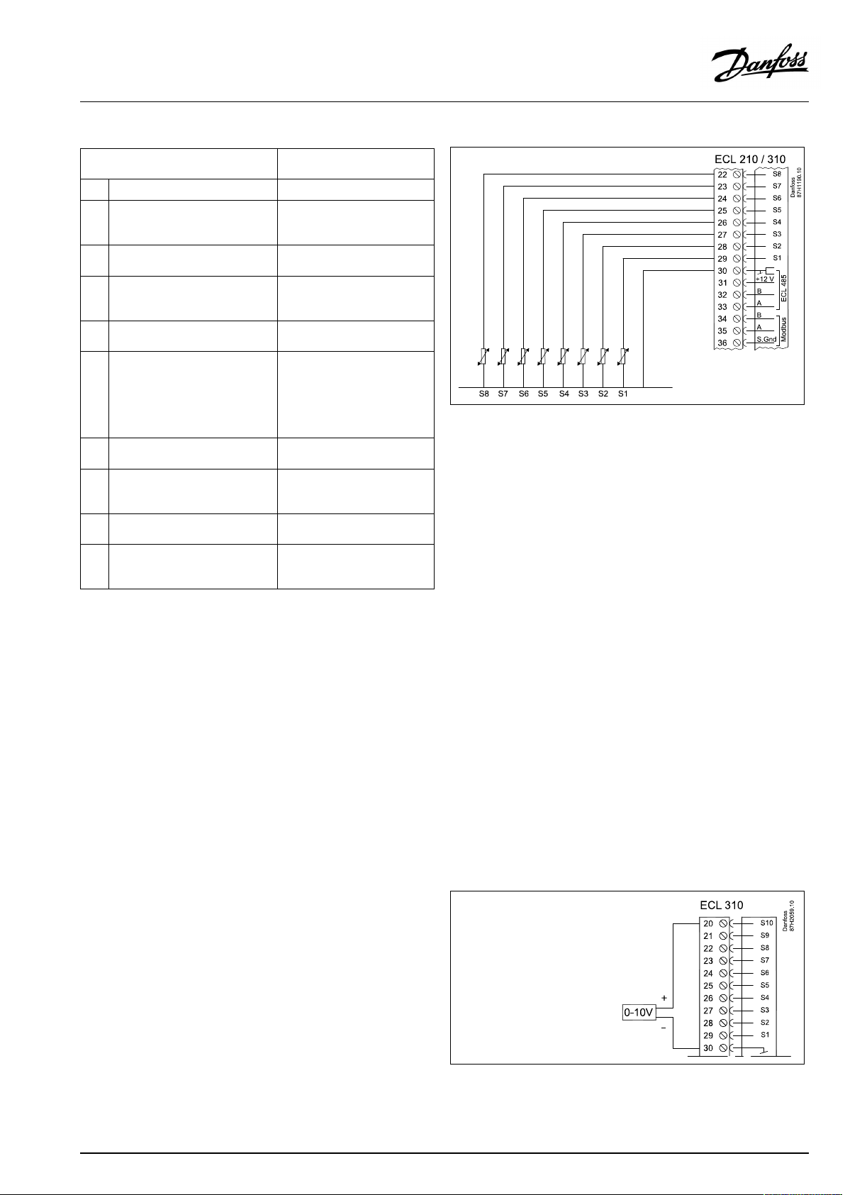
OperatingGuideECLComfort210/296/310,applicationA275/A375
A375:
Sensor/description
S1
Outdoortemperaturesensor*
A375.3,A375.5:
S2
Returntemperaturesensor,
circuit2
S3
Boilertemperaturesensor**,
circuit1
A375.3,A375.5:
S4
Flowtemperaturesensor**,
circuit2
S5Returntemperaturesensor,
circuit1
A375.2:
S6
DHWtanktemperaturesensor,
circuit2.
A375.3,A375.5:
DHWtanktemperaturesensor,
circuit3.
S7
Roomtemperaturesensor***,
circuit1
A375.3,A375.5
S8
Roomtemperaturesensor***,
circuit2
A375.4,A375.5:
S9
Pressuretransmitter,0-10V.
S10
Voltagesignal(0–10V)for
externalcontrolofdesired
boilertemperature,circuit1.
Type
(recomm.)
ESMT
ESM-11/ESMB/
ESMC/ESMU
ESMU/ESMB
ESM-11/ESMB/
ESMC/ESMU
ESM-11/ESMB/
ESMC/ESMU
ESM-11/ESMB/
ESMC/ESMU
ESM-10
ESM-10
*
Iftheoutdoortemperaturesensorisnotconnectedorthe
cableisshort-circuited,thecontrollerassumesthatthe
outdoortemperatureis0(zero)°C.
**
Theboiler/flowtemperaturesensormustalwaysbe
connectedinordertohavethedesiredfunctionality.
•Iftheboilersensorisnotconnected,orthecableis
short-circuited,theboilerwillbeswitchedOFF(safety
function).
•Iftheflowsensorisnotconnected,orthecableis
short-circuited,themotorizedcontrolvalvecloses(safety
function).
***
Onlyforroomtemperaturesensorconnection.Theroom
temperaturesignalcanalsobeavailablefromaRemote
ControlUnit(ECA30/31).See'Electricalconnections,ECA
30/31'.
SubtypesA375.1,A375.2andA375.3only:
Connectionofvoltagesignal(0–10V)forexternalcontrolof
desiredboilertemperature
AQ042286456873en-010501
©Danfoss|2021.04|55
Page 56

OperatingGuideECLComfort210/296/310,applicationA275/A375
A375.4,A375.5
Connectionofpressuretransmitter.
SeetheInstallationGuide(deliveredwiththeapplicationkey).
ScaleforconversionofvoltagetopressureissetintheECLComfort
(navigation:Circuit1>MENU>Alarm>S9pressure).
Thepressuretransmitterispoweredwith12-24Vd.c.
Outputtype:0-10V.
2.5.5Electricalconnections,ECA30/31
Terminal
ECL
*
Afteranexternalroomtemperaturesensorhasbeenconnected,
ECA30/31mustberepowered.
ThecommunicationtotheECA30/31mustbesetupintheECL
Comfortcontrollerin'ECAaddr.'
TheECA30/31mustbesetupaccordingly.
AfterapplicationsetuptheECA30/31isreadyafter2–5min.A
progressbarintheECA30/31isdisplayed.
Connectionofswitchforexternaloverride
Terminal
ECA30/31
30
31
322
333
4
1
4
5
Description
Twistedpair
Twistedpair
Ext.roomtemperature
sensor*
Type
(recomm.)
Cable2x
twistedpair
ESM-10
56|©Danfoss|2021.04
Usinganinputforoverriderequiresavoltfreecontact/switch.
IfS1...S6ischosenasoverrideinput,theoverrideswitchmusthave
gold-platedcontacts.
IfS7...S16ischosenasoverrideinput,theoverrideswitchcanbea
standardcontact.
AQ042286456873en-010501
Page 57

OperatingGuideECLComfort210/296/310,applicationA275/A375
Wirecrosssectionforsensorconnections:Min.0.4mm².
Totalcablelength:Max.200m(allsensorsincl.internalECL485
communicationbus)
Cablelengthsofmorethan200mmaycausenoisesensibility(EMC).
Iftheactualapplicationcontainstwoheatingcircuits,itispossible
toconnectanECA30/31toeachcircuit.Theelectricalconnections
aredoneinparallel.
Max.2ECA30/31canbeconnectedtoanECLComfort310controller
ortoECLComfort210/296/310controllersinamaster-slavesystem.
ECAinformationmessage:
‘Applicationreq.newerECA’:
Thesoftware(firmware)ofyourECAdoesnotcomplywiththe
software(firmware)ofyourECLComfortcontroller.Pleasecontact
yourDanfosssalesoffice.
Totalcablelength:Max.200m(allsensorsincl.internalECL485
communicationbus).
Cablelengthsofmorethan200mmaycausenoisesensibility(EMC).
Max.twoECA30/31canbeconnectedtoanECLComfortcontroller
ortomaster/slavesystemswithseveralECLComfortcontrollers.
AQ042286456873en-010501
©Danfoss|2021.04|57
Page 58
OperatingGuideECLComfort210/296/310,applicationA275/A375
2.5.6Electricalconnections,master/slavesystems
Thecontrollercanbeusedasmasterorslaveinmaster/slave
systemsviatheinternalECL485communicationbus(2xtwisted
paircable).
TheECL485communicationbusisnotcompatiblewiththeECL
businECLComfort110,200,300and301!
Terminal
Description
Type
(recomm.)
30
Commonterminal
+12V*,ECL485communicationbus
31
*OnlyforECA30/31andmaster/
slavecommunication
32
B,ECL485communicationbus
33
A,ECL485communicationbus
Cable2x
twistedpair
ECL485buscable
MaximumrecommendedlengthoftheECL485busiscalculatedlike
this:
Subtract"TotallengthofallinputcablesofallECLcontrollersinthe
master-slavesystem"from200m.
Simpleexamplefortotallengthofallinputcables,3xECL:
1xECL
3xECL
3xECLReturntemp.sensor:
3xECLRoomtemp.sensor:
Total:
Outdoortemp.sensor:
Flowtemp.sensor:
15m
18m
18m
30m
81m
Electricalconnections,Modbus
ECLComfort210:Non-galvanicisolatedModbusconnections
ECLComfort296:GalvanicisolatedModbusconnections
ECLComfort310:GalvanicisolatedModbusconnections
2.5.7Electricalconnections,communication
Electricalconnections,M-bus
ECLComfort210:Notimplemented
ECLComfort296:Onboard,non-galvanicisolated.Max.cable
length50m.
ECLComfort310:Onboard,non-galvanicisolated.Max.cable
length50m.
MaximumrecommendedlengthoftheECL485bus:
200-81m=119m
58|©Danfoss|2021.04
AQ042286456873en-010501
Page 59

OperatingGuideECLComfort210/296/310,applicationA275/A375
2.6InsertingtheECLApplicationKey
2.6.1InsertingtheECLApplicationKey
TheECLApplicationKeycontains
•theapplicationanditssubtypes,
•currentlyavailablelanguages,
•factorysettings:e.g.schedules,desiredtemperatures,
limitationvaluesetc.Itisalwayspossibletorecoverthefactory
settings,
•memoryforusersettings:specialuser/systemsettings.
Afterhavingpowered-upthecontroller,differentsituationsmight
beexisting:
1.Thecontrollerisnewfromthefactory,theECLApplicationKey
isnotinserted.
2.Thecontrolleralreadyrunsanapplication.TheECLApplication
Keyisinserted,buttheapplicationneedstobechanged.
3.Acopyofthecontrollerssettingsisneededforconfiguring
anothercontroller.
ECLComfort210/310
ECLComfort210/310
Usersettingsare,amongothers,desiredroomtemperature,desired
DHWtemperature,schedules,heatcurve,limitationvaluesetc.
Systemsettingsare,amongothers,communicationset-up,display
brightnessetc.
AQ042286456873en-010501
ECLComfort296
©Danfoss|2021.04|59
Page 60

OperatingGuideECLComfort210/296/310,applicationA275/A375
Automaticupdateofcontrollersoftware(firmware):
Thesoftwareofthecontrollerisupdatedautomaticallywhenthekey
isinserted(asofcontrollerversion1.11(ECL210/310)andversion
1.58(ECL296)).Thefollowinganimationwillbeshownwhenthe
softwareisbeingupdated:
Progressbar
Duringupdate:
•DonotremovetheKEY
Ifthekeyisremovedbeforethehour-glassisshown,youhave
tostartafresh.
•Donotdisconnectthepower
Ifthepowerisinterruptedwhenthehour-glassisshown,the
controllerwillnotwork.
•Manualupdateofcontrollersoftware(firmware):
Seethesection"Automatic/manualupdateoffirmware"
60|©Danfoss|2021.04
AQ042286456873en-010501
Page 61

OperatingGuideECLComfort210/296/310,applicationA275/A375
ApplicationKey:Situation1
Thecontrollerisnewfromthefactory,theECLApplicationKey
isnotinserted.
AnanimationfortheECLApplicationKeyinsertionisdisplayed.
InserttheApplicationKey.
ApplicationKeynameandVersionisindicated(example:A266
Ver.1.03).
IftheECLApplicationKeyisnotsuitableforthecontroller,a"cross"
isdisplayedovertheECLApplicationKey-symbol.
Action:Purpose:
Selectlanguage
Confirm
Selectapplication(subtype)
Somekeyshaveonlyoneapplication.
Confirmwith‘Yes’
Set'Time&Date'
Turnandpushthedialtoselectand
change'Hours' ,'Minutes','Date',
'Month'and'Year' .
Choose''Next'
Confirmwith‘Yes’
Goto‘Aut.daylight’
Choosewhether‘ Aut.daylight´*
shouldbeactiveornot
*‘Aut.daylight’istheautomaticchangeoverbetweensummer
andwintertime.
DependingonthecontentsoftheECLApplicationKey,procedure
AorBistakingplace:
A
TheECLApplicationkeycontainsfactorysettings:
Thecontrollerreads/transfersdatafromtheECLApplicationKey
toECLcontroller.
Examples:
YESorNO
Theapplicationisinstalled,andthecontrollerresetsandstartsup.
B
TheECLApplicationkeycontainschangedsystemsettings:
Pushthedialrepeatedly.
’NO’:
’YES*:
Ifthekeycontainsusersettings:
Pushthedialrepeatedly.
‘NO:
‘YES*:
*If‘YES’cannotbechosen,theECLApplicationKeydoesnot
containanyspecialsettings.
Choose‘Startcopying’andconfirmwith'Yes'.
AQ042286456873en-010501
OnlyfactorysettingsfromtheECLApplicationKeywill
becopiedtothecontroller.
Specialsystemsettings(differingfromthefactory
settings)willbecopiedtothecontroller.
OnlyfactorysettingsfromtheECLApplicationKeywill
becopiedtothecontroller.
Specialusersettings(differingfromthefactorysettings)
willbecopiedtothecontroller.
©Danfoss|2021.04|61
Page 62

OperatingGuideECLComfort210/296/310,applicationA275/A375
ApplicationKey:Situation2
Thecontrolleralreadyrunsanapplication.TheECLApplication
Keyisinserted,buttheapplicationneedstobechanged.
TochangetoanotherapplicationontheECLApplicationKey,the
currentapplicationinthecontrollermustbeerased(deleted).
BeawarethattheApplicationKeymustbeinserted.
Action:Purpose:
Choose‘MENU’inanycircuit
Confirm
Choosethecircuitselectoratthetop
rightcornerinthedisplay
Confirm
Choose‘Commoncontrollersettings’
Confirm
Choose‘Keyfunctions’
Confirm
Choose‘Eraseapplication’
Confirmwith‘Yes’
Thecontrollerresetsandisreadytobeconfigured.
Followtheproceduredescribedinsituation1.
Examples:
62|©Danfoss|2021.04
AQ042286456873en-010501
Page 63
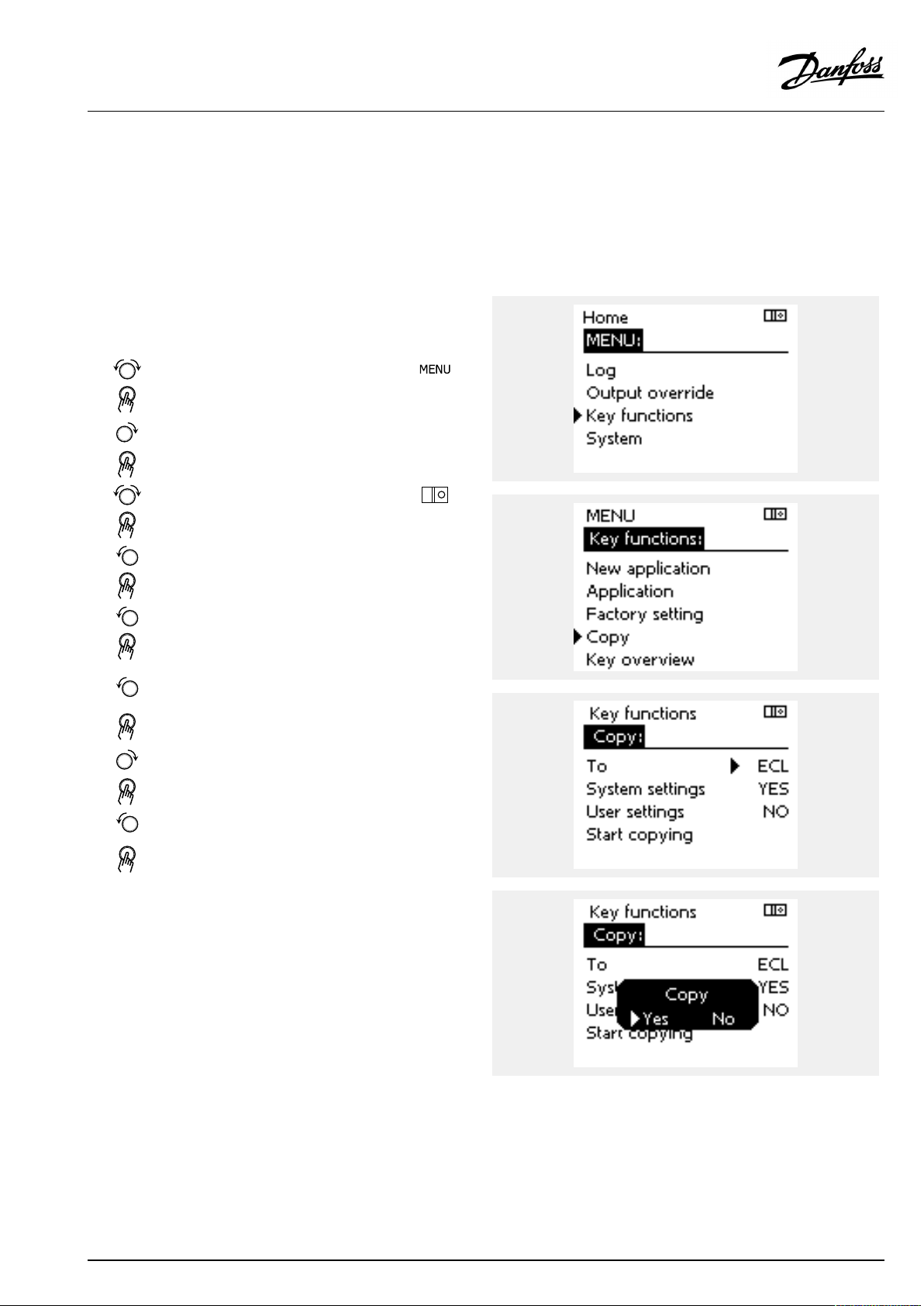
OperatingGuideECLComfort210/296/310,applicationA275/A375
ApplicationKey:Situation3
Acopyofthecontrollerssettingsisneededforconfiguring
anothercontroller.
Thisfunctionisused
•forsaving(backup)ofspecialuserandsystemsettings
•whenanotherECLComfortcontrollerofthesametype(210,
296or310)mustbeconfiguredwiththesameapplicationbut
user/systemsettingsdifferfromthefactorysettings.
HowtocopytoanotherECLComfortcontroller:
Action:Purpose:
Choose‘MENU’
Confirm
Choosethecircuitselectoratthetop
rightcornerinthedisplay
Confirm
Choose'Commoncontrollersettings'
Confirm
Goto‘Keyfunctions’
Confirm
Choose‘Copy’
Confirm
Choose‘To’ .
‘ECL’or‘KEY’willbeindicated.Choose
’ECL’orKEY’
Pushthedialrepeatedlytochoose
copydirection
Choose‘Systemsettings’or‘User
settings’
Pushthedialrepeatedlytochoose
‘Yes’or‘No’in‘Copy’ .Pushtoconfirm.
Choose‘Startcopying’
TheApplicationKeyorthecontroller
isupdatedwithspecialsystemoruser
settings.
Examples:
*
’ECL’or‘KEY’ .
**
‘NO’or‘YES’
*
‘ECL’:
‘KEY’:
**
‘NO’:
‘YES’:
AQ042286456873en-010501
DatawillbecopiedfromtheApplicationKeytothe
ECLController.
DatawillbecopiedfromtheECLControllertothe
ApplicationKey.
ThesettingsfromtheECLcontrollerwillnotbecopied
totheApplicationKeyortotheECLComfortcontroller.
Specialsettings(differingfromthefactorysettings)will
becopiedtotheApplicationKeyortotheECLComfort
controller.IfYEScannotbechosen,therearenospecial
settingstobecopied.
©Danfoss|2021.04|63
Page 64

OperatingGuideECLComfort210/296/310,applicationA275/A375
Language
Atapplicationupload,alanguagemustbeselected.*
IfanotherlanguagethanEnglishisselected,theselectedlanguage
ANDEnglishwillbeuploadedintotheECLcontroller.
ThismakesserviceeasyforEnglishspeakingservicepeople,just
becausetheEnglishlanguagemenuscanbevisiblebychanging
theactualsetlanguageintoEnglish.
(Navigation:MENU>Commoncontroller>System>Language)
Iftheuploadedlanguageisnotsuitable,theapplicationmustbe
erased.UserandSystemsettingscanbesavedontheapplication
keybeforeerasing.
Afternewuploadwithpreferredlanguage,theexistingUserand
Systemsettingscanbeuploaded.
*)
(ECLComfort310,24Volt)Iflanguagecannotbeselected,the
powersupplyisnota.c.(alternatingcurrent).
2.6.2ECLApplicationKey,copyingdata
Generalprinciples
Whenthecontrollerisconnectedandoperating,youcancheck
andadjustallorsomeofthebasicsettings.Thenewsettingscan
bestoredontheKey.
Factorysettingscanalwaysberestored.
HowtoupdatetheECLApplicationKeyaftersettingshave
beenchanged?
AllnewsettingscanbestoredontheECLApplicationKey.
Howtostorefactorysettinginthecontrollerfromthe
ApplicationKey?
PleasereadtheparagraphconcerningApplicationKey,Situation
1:Thecontrollerisnewfromthefactory,theECLApplicationKey
isnotinserted.
HowtostorepersonalsettingsfromthecontrollertotheKey?
PleasereadtheparagraphconcerningApplicationKey,Situation3:
Acopyofthecontrollerssettingsisneededforconfiguringanother
controller
Asamainrule,theECLApplicationKeyshouldalwaysremainin
thecontroller.IftheKeyisremoved,itisnotpossibletochange
settings.
Makeanoteofnewsettingsinthe'Settingsoverview'table.
DonotremovetheECLApplicationKeywhilecopying.Thedataon
theECLApplicationKeycanbedamaged!
ItispossibletocopysettingsfromoneECLComfortcontrollerto
anothercontrollerprovidedthatthetwocontrollersarefromthesame
series(210or310).
Furthermore,whentheECLComfortcontrollerhasbeenuploaded
withanapplicationkey,minimumversion2.44,itispossibletoupload
personalsettingsfromapplicationkeys,minimumversion2.14.
64|©Danfoss|2021.04
AQ042286456873en-010501
Page 65

OperatingGuideECLComfort210/296/310,applicationA275/A375
The“Keyoverview”doesnotinform—throughECA30/31—about
thesubtypesoftheapplicationkey.
Keyinserted/notinserted,description:
ECLComfort210/310,controllerversionslowerthan1.36:
-
Takeouttheapplicationkey;for20minutes
settingscanbechanged.
-
Powerupthecontrollerwithoutthe
applicationkeyinserted;for20minutes
settingscanbechanged.
ECLComfort210/310,controllerversions1.36andup:
-
Takeouttheapplicationkey;for20minutes
settingscanbechanged.
-
Powerupthecontrollerwithoutthe
applicationkeyinserted;settingscannotbe
changed.
ECLComfort296,controllerversions1.58andup:
-
Takeouttheapplicationkey;for20minutes
settingscanbechanged.
-
Powerupthecontrollerwithoutthe
applicationkeyinserted;settingscannotbe
changed.
AQ042286456873en-010501
©Danfoss|2021.04|65
Page 66

OperatingGuideECLComfort210/296/310,applicationA275/A375
2.7Checklist
IstheECLComfortcontrollerreadyforuse?
Makesurethatthecorrectpowersupplyisconnectedtoterminals9and10(230Vor24V).
Makesurethecorrectphaseconditionsareconnected:
230V:Live=terminal9andNeutral=terminal10
24V:SP=terminal9andSN=terminal10
Checkthattherequiredcontrolledcomponents(actuator,pumpetc.)areconnectedtothecorrectterminals.
Checkthatallsensors/signalsareconnectedtothecorrectterminals(see'Electricalconnections').
Mountthecontrollerandswitchonthepower.
IstheECLApplicationKeyinserted(see'InsertingtheApplicationKey').
DoestheECLComfortcontrollercontainanexistingapplication(see'InsertingtheApplicationKey').
Isthecorrectlanguagechosen(see'Language'in'Commoncontrollersettings').
Isthetime&datesetcorrectly(see'Time&Date'in'Commoncontrollersettings').
Istherightapplicationchosen(see'Identifyingthesystemtype').
Checkthatallsettingsinthecontroller(see'Settingsoverview')aresetorthatthefactorysettingscomplywithyour
requirements.
Choosemanualoperation(see'Manualcontrol').Checkthatvalvesopenandclose,andthatrequiredcontrolled
components(pumpetc.)startandstopwhenoperatedmanually.
Checkthatthetemperatures/signalsshowninthedisplaymatchtheactualconnectedcomponents.
Havingcompletedthemanualoperationcheck,choosecontrollermode(scheduled,comfort,savingorfrostprotection).
66|©Danfoss|2021.04
AQ042286456873en-010501
Page 67

OperatingGuideECLComfort210/296/310,applicationA275/A375
2.8Navigation,ECLApplicationKeyA275
Navigation,A275,circuits1,2and3
Home
A275.1A275.2A275.3
CircuitCircuitCircuit
MENU
Schedule
Settings
FlowtemperatureHeatcurve((((
Tanktemperature1219313193
Roomlimit
Returnlimit
Optimization
Controlpar.
Boiler
IDnos.
1117812178
11177
1118212182
1118312183
1101512015
1103112031
1103212032
1103312033
1103412034
1103512035
1103612036
1103712037
1108512085
1101112011
1101212012
1101412014
1102612026
1102012020
1102112021
1117912179
11046
11049
11071
11038
11047
Function
Temp.max.
12177
1219513195
1219413194
12013
12174
12184
12185
12186
12187
12189
Temp.min.
Chargedifference
Startdifference
Stopdifference
Infl.-max.
Infl.-min.
Adapt.time
HighToutX1
LowlimitY1
LowToutX2
HighlimitY2
Infl.-max.
Infl.-min.
Adapt.time
Priority
Autosaving
Boost
Ramp
Optimizer
Pre-stop
Basedon
Totalstop
Summer,Cut-out
Motorpr.
Xp
Tn
Mrun
Nz
Min.act.time
Difference
Max.Tlimit
Min.ONtime
StopatTout
Protection
11
((((((
((((
((((
((((
((((
((((
((((
((((
((((
((((
((((
((((
((((
((((
((((
((((
((((
((((
((((
((((
((((
(((
(((
(((
(((
(((
ApplicationA275
2
((
((
((
1
23
(
(
(
(
(
(
(
AQ042286456873en-010501
©Danfoss|2021.04|67
Page 68

OperatingGuideECLComfort210/296/310,applicationA275/A375
Navigation,A275,circuits1,2and3,continued
Home
MENU
Settings
Holiday
Alarm
Anti-bacteria
Influenceoverview
Des.flowT
Des.DHWT
Application
Temp.monitor.
Alarmoverview
ApplicationA275
A275.1A275.2A275.3
CircuitCircuitCircuit
IDnos.
1101012010ECAaddr.((((
11017
11050
1205113051
1205313053
1204113041
115001250013500
1102212022
12023
12052
12076
1107712077
1107812078
1104012040
110931209313093
11141
1214113141
111421214213142
12147
12148
12149
12150
Function
Demandoffset
Pdemand
Ch.-o.valve/P
Tank,sec./prim.
DHWPpost-run
SenddesiredT
Pexercise
Mexercise
DHWpriority
Circ.PfrostT
PfrostT
PheatT
Ppost-run
Frostpr.T
Ext.input
Ext.mode
Upperdifference
Lowerdifference
Delay
Lowesttemp.
11
(((
(((
((((((
((((
((((
((((
((((
((((((
((((((
((((((
((((((
((((
2
((
((
((
(
((
((
1
23
(
(
(
(
(
(
(
68|©Danfoss|2021.04
AQ042286456873en-010501
Page 69

OperatingGuideECLComfort210/296/310,applicationA275/A375
Navigation,applicationA275,Commoncontrollersettings
Home
MENU
Time&Date
HolidaySelectable
Inputoverview1
Inputoverview2
Inputoverview3
Log1(sensors)
Log2(sensors)
Log3(sensors)
Outputoverride
OutdoorTLogtoday
RoomT
RoomT&desiredLog2days
BoilerT&desiredLog4days
ReturnT&limit
OutdoorTLogtoday
RoomT
FlowT&desiredLog2days
ReturnT&limitLog4days
TankT&desired
TankT&desiredLogtoday
IDno.
ApplicationA275,Commoncontrollersettings
Function
Selectable
OutdoorT
Outdooracc.T
RoomT
BoilerT
ReturnT
OutdoorT
Outdooracc.T
RoomT
FlowT
ReturnT
TankT
TankT
Logyesterday
Logyesterday
Logyesterday
Log2days
Log4days
P1
B1
M2
P4
P3
A1
A275.1A275.2A275.3
(((
(((
(((
(((
(((
(((
(((
(
(
(
(
(
(
(
(((
((
((
(((
(((
(
(
(
(
(
(
(((
(((
(
(
((
((
AQ042286456873en-010501
©Danfoss|2021.04|69
Page 70

OperatingGuideECLComfort210/296/310,applicationA275/A375
Navigation,applicationA275,Commoncontrollersettings,continued
Home
MENU
Keyfunctions
SystemECLversion
ApplicationA275,Commoncontrollersettings
IDno.
NewapplicationEraseapplication
Application
FactorysettingSystemsettings
Copy
Keyoverview
Extension
Ethernet
Portalconfig
M-busconfig
EnergyMeters
Rawinputoverview
Sensoroffset
Alarm
Display
Communication
Language
60058
60059
38
39
2048
2150
2151
2050
Function
Usersettings
Gotofactory
To
Systemsettings
Usersettings
Startcopying
Codeno.
Hardware
Software
Buildno.
Serialno.
Productiondate
32:Tsensordefekt
Backlight
Contrast
Modbusaddr.
Baud
ECL485addr.
Servicepin
Ext.reset
Language
A275.1A275.2A275.3
(((
(((
(((
(((
(((
(((
(((
(((
(((
(((
(((
(((
(((
(((
(((
(((
(((
(((
(((
(((
(((
(((
(((
(((
(((
(((
(((
(((
(((
(((
(((
(((
70|©Danfoss|2021.04
AQ042286456873en-010501
Page 71

OperatingGuideECLComfort210/296/310,applicationA275/A375
Navigation,A375.1,A375.2andA375.3,circuits1,2and3
Home
MENU
Schedule
Schedulecirc.P
Settings
ApplicationA375
A375.1A375.2A375.3
CircuitCircuitCircuit
IDnos.
FlowtemperatureHeatcurve((((
1117812178
11177
12177
Tanktemperature1219313193
1219513195
1219413194
Roomlimit
Returnlimit
Optimization
Controlpar.
Boiler
1118212182
1118312183
1101512015
1103112031
1103212032
1103312033
1103412034
1103512035
1103612036
1103712037
1108512085
1101112011
1101212012
12013
1101412014
1102612026
1102012020
1102112021
1117912179
12174
12184
12185
12186
12187
12189
12024
11046
11049
11071
11072
11038
11047
11048
11074
11075
11073
Function
Temp.max.
Temp.min.
Ext.desiredT
Chargedifference
Startdifference
Stopdifference
Infl.-max.
Infl.-min.
Adapt.time
HighToutX1
LowlimitY1
LowToutX2
HighlimitY2
Infl.-max.
Infl.-min.
Adapt.time
Priority
Autosaving
Boost
Ramp
Optimizer
Pre-stop
Basedon
Totalstop
Summer,cut-out
Motorpr.
Xp
Tn
Mrun
Nz
Min.act.time
Actuator
Difference
Max.Tlimit
Min.ONtime
Sequencetype
StopatTout
Protection
Bandlimit
Reaction,o.band
Reaction,inband
Steps
11
((((((
((((
((((
(((
((((
((((
((((
((((
((((
((((
((((
((((
((((
((((
((((
((((
((((
((((
((((
((((
((((
((((
(((
(((
(((
(((
(((
(((
(((
(((
(((
(((
2
(
((
((
((
1
23
(
(
(
(
(
(
(
(
AQ042286456873en-010501
©Danfoss|2021.04|71
Page 72

OperatingGuideECLComfort210/296/310,applicationA275/A375
Navigation,A375.1,A375.2andA375.3,circuits1,2and3,continued
Home
MENU
Settings
Holiday
Alarm
Anti-bacteria
Influenceoverview
Des.flowT
Des.DHWT
Application
Temp.monitor.
Alarmoverview
ApplicationA375
A375.1A375.2A375.3
CircuitCircuitCircuit
IDnos.
1101012010ECAaddr.((((
11017
11050
1205113051
1205313053
12055
1204113041
115001250013500
1102212022
12023
12052
12076
1107712077
1107812078
1104012040
110931209313093
11141
1214113141
111421214213142
12147
12148
12149
12150
Function
Demandoffset
Pdemand
Ch.-o.valve/P
Tank,sec./prim.
Circ.Ppriority
DHWPpost-run
SenddesiredT
Pexercise
Mexercise
DHWpriority
Circ.PfrostT
PfrostT
PheatT
Ppost-run
Frostpr.T
Ext.input
Ext.mode
Upperdifference
Lowerdifference
Delay
Lowesttemp.
11
(((
(((
((((((
((((
((((
((((
((((
((((((
((((((
((((((
((((((
((((
2
((
((
(
((
(
((
((
1
23
(
(
(
(
(
(
(
72|©Danfoss|2021.04
AQ042286456873en-010501
Page 73

OperatingGuideECLComfort210/296/310,applicationA275/A375
Navigation,applicationA375.1,A375.2andA375.3,Commoncontrollersettings
Home
MENU
Time&Date
HolidaySelectable
Inputoverview1
Inputoverview2
Inputoverview3
Log1(sensors)
Log2(sensors)
Log3(sensors)
Outputoverride
OutdoorTLogtoday
RoomT
RoomT&desiredLog2days
BoilerT&desiredLog4days
ReturnT&limit
OutdoorTLogtoday
RoomT&desiredLogyesterday
FlowT&desiredLog2days
ReturnT&limitLog4days
TankT&desired
TankT&desiredLogtoday
IDno.
ApplicationA375,Commoncontrollersettings
Function
Selectable
OutdoorT
Outdooracc.T
RoomT
BoilerT
ReturnT
Ext.desiredT
OutdoorT
Outdooracc.T
RoomT
FlowT
ReturnT
TankT
TankT
Logyesterday
Logyesterday
Log2days
Log4days
P1
B1
B2
B3
B4
B5
B6
B7
B8
M2
P4
P3
A1
A375.1A375.2A375.3
(((
(((
(((
(((
(((
(((
(((
(((
(
(
(
(
(
(
(
(((
(
((
(((
(((
(
(
(
(
(
(
(
(
(
(((
(((
(((
(((
(((
(((
(((
(((
(((
(
((
((
(((
AQ042286456873en-010501
©Danfoss|2021.04|73
Page 74

OperatingGuideECLComfort210/296/310,applicationA275/A375
Navigation,applicationA375.1,A375.2andA375.3,Commoncontrollersettings,continued
Home
MENU
Keyfunctions
SystemECLversion
ApplicationA375,Commoncontrollersettings
IDno.
NewapplicationEraseapplication
Application
FactorysettingSystemsettings
Copy
Keyoverview
Extension
Ethernet
Portalconfig
M-busconfig
EnergyMeters
Rawinputoverview
Sensoroffset
Alarm
Display
Communication
Language
60058
60059
38
39
2048
2150
2151
2050
Function
Usersettings
Gotofactory
To
Systemsettings
Usersettings
Startcopying
Codeno.
Hardware
Software
Buildno.
Serialno.
Productiondate
32:Tsensordefekt
Backlight
Contrast
Modbusaddr.
Baud
ECL485addr.
Servicepin
Ext.reset
Language
A375.1A375.2A375.3
(((
(((
(((
(((
(((
(((
(((
(((
(((
(((
(((
(((
(((
(((
(((
(((
(((
(((
(((
(((
(((
(((
(((
(((
(((
(((
(((
(((
(((
(((
(((
(((
74|©Danfoss|2021.04
AQ042286456873en-010501
Page 75

OperatingGuideECLComfort210/296/310,applicationA275/A375
Navigation,A375.4andA375.5,circuits1,2and3
Home
MENU
Schedule
Schedulecirc.P
Settings
ApplicationA375
A375.4A375.5
CircuitCircuit
IDnos.
FlowtemperatureHeatcurve(((
1117812178
11177
11004
Tanktemperature13193
Roomlimit
Returnlimit
Optimization
Controlpar.
Boiler
1118212182
1118312183
1101512015
1103112031
1103212032
1103312033
1103412034
1103512035
1103612036
1103712037
1108512085
11029
11028
1101112011
1101212012
1101412014
1102612026
1102012020
1102112021
1117912179
11607
11608
11424
11046
11364
11184
11185
11186
11187
11189
12177
12013
12174
12184
12185
12186
12187
12189
12024
13195
13194
Function
Temp.max.
Temp.min.
DesiredT
Chargedifference
Startdifference
Stopdifference
Infl.-max.
Infl.-min.
Adapt.time
HighToutX1
LowlimitY1
LowToutX2
HighlimitY2
Infl.-max.
Infl.-min.
Adapt.time
Priority
DHW,ret.Tlimit
Con.T,ret.Tlim.
Autosaving
Boost
Ramp
Optimizer
Pre-stop
Basedon
Totalstop
Summer,cut-out
Motorpr.
Xp
Tn
Mrun
Nz
Min.act.time
Actuator
Controlvoltage
LowX
HighX
Min.offtime
Difference
Control,delay
Xp
Tn
Mrun
Nz
Min.act.time
11
((((
(((
(((
((
(((
(((
(((
(((
(((
(((
(((
(((
(((
(((
(((
((
((
(((
(((
(((
(((
(((
(((
(((
((
((
((
((
((
((
((
((
((
((
((
23
(
(
(
(
(
(
(
(
(
(
(
(
AQ042286456873en-010501
©Danfoss|2021.04|75
Page 76

OperatingGuideECLComfort210/296/310,applicationA275/A375
Navigation,A375.4andA375.5,circuits1,2and3,continued
Home
MENU
Settings
Holiday
Alarm
Anti-bacteria
Influenceoverview
Des.flowT
Des.DHWT
Application
S9pressure
Temp.monitor.
Alarmoverview
ApplicationA375
A375.4A375.5
CircuitCircuit
IDnos.
1101012010ECAaddr.(((
11017
11050
115001250013500
1102212022
12023
12052
12076
1107712077
1107812078
1104012040
110931209313093
11141
1214113141
111421214213142
12147
12148
12149
12150
13051
13053
13041
13607
13608
13614
13615
13617
Function
Demandoffset
Pdemand
Ch.-o.valve/P
Tank,sec./prim.
Circ.Ppriority
DHWPpost-run
SenddesiredT
Pexercise
Mexercise
DHWpriority
Circ.PfrostT
PfrostT
PheatT
Ppost-run
Frostpr.T
Ext.input
Ext.mode
Pressure
LowX
HighX
Alarmhigh
Alarmlow
Alarmtime-out
Upperdifference
Lowerdifference
Delay
Lowesttemp.
11
((
((
((((
(((
(((
(((
(((
((((
((((
((((
((((
((
((
((
((
((
((
(((
(((
23
(
(
(
(
(
(
(
(
(
(
(
76|©Danfoss|2021.04
AQ042286456873en-010501
Page 77

OperatingGuideECLComfort210/296/310,applicationA275/A375
Navigation,applicationA375.4andA375.5,Commoncontrollersettings
Home
MENU
Time&Date
HolidaySelectable
Inputoverview1
Inputoverview2
Inputoverview3
Log1(sensors)
Log2(sensors)
Log3(sensors)
Outputoverride
OutdoorTLogtoday
RoomT&desiredLogyesterday
BoilerT&desiredLog2days
ReturnT&limitLog4days
Pressure
OutdoorTLogtoday
RoomT&desiredLogyesterday
FlowT&desiredLog2days
ReturnT&limitLog4days
TankT&desiredLogtoday
IDno.
ApplicationA375,Commoncontrollersettings
Function
Selectable
OutdoorT
Outdooracc.T
RoomT
BoilerT
ReturnT
Pressure
OutdoorT
Outdooracc.T
RoomT
FlowT
ReturnT
TankT
Logyesterday
Log2days
Log4days
P1
B1
M2
M3
P4
P3
P5
A1
V1
A375.4A375.5
((
((
((
((
((
((
((
((
(
(
(
(
(
(
((
(
((
((
((
(
(
(
(
(
(
(
(
((
((
(
((
(
(
(
((
((
AQ042286456873en-010501
©Danfoss|2021.04|77
Page 78

OperatingGuideECLComfort210/296/310,applicationA275/A375
Navigation,applicationA375.4andA375.5,Commoncontrollersettings,continued
Home
MENU
Keyfunctions
SystemECLversion
ApplicationA375,Commoncontrollersettings
IDno.
NewapplicationEraseapplication
Application
FactorysettingSystemsettings
Copy
Keyoverview
Extension
Ethernet
Portalconfig
M-busconfig
EnergyMeters
Rawinputoverview
Sensoroffset
Alarm
Display
Communication
Language
60058
60059
38
39
2048
2150
2151
2050
Function
Usersettings
Gotofactory
To
Systemsettings
Usersettings
Startcopying
Codeno.
Hardware
Software
Buildno.
Serialno.
Productiondate
32:Tsensordefekt
Backlight
Contrast
Modbusaddr.
Baud
ECL485addr.
Servicepin
Ext.reset
Language
A375.4A375.5
((
((
((
((
((
((
((
((
((
((
((
((
((
((
((
((
((
((
((
((
((
((
((
((
((
((
((
((
((
((
((
((
78|©Danfoss|2021.04
AQ042286456873en-010501
Page 79

OperatingGuideECLComfort210/296/310,applicationA275/A375
3.0Dailyuse
3.1Howtonavigate
Younavigateinthecontrollerbyturningthedialleftorrightto
thedesiredposition().
Thedialhasabuilt-inaccellerator.Thefasteryouturnthedial,the
fasteritreachesthelimitsofanywidesettingrange.
Thepositionindicatorinthedisplay(
youare.
Pushthedialtoconfirmyourchoices().
Thedisplayexamplesarefromatwo-circuitapplication:One
heatingcircuit()andonedomestichot-water(DHW)circuit().
Theexamplesmightdifferfromyourapplication.
)willalwaysshowyouwhere
ExampleshowsECL210/310
Heatingcircuit():DHWcircuit();
Somegeneralsettingswhichapplytotheentirecontrollerare
locatedinaspecificpartofthecontroller.
Toenter‘Commoncontrollersettings’:
Action:Purpose:
Choose‘MENU’inanycircuit
Confirm
Choosethecircuitselectoratthetop
rightcornerinthedisplay
Confirm
Choose‘Commoncontrollersettings’
Confirm
Examples:
Circuitselector
AQ042286456873en-010501
©Danfoss|2021.04|79
Page 80

OperatingGuideECLComfort210/296/310,applicationA275/A375
3.2Understandingthecontrollerdisplay
ThissectiondescribesthefunctioningeneralfortheECLComfort
210/296/310series.Theshowndisplaysaretypicalandnot
applicationrelated.Theymightdifferfromthedisplaysinyour
application.
Choosingafavoritedisplay
Yourfavoritedisplayisthedisplayyouhavechosenasthedefault
display.Thefavoritedisplaywillgiveyouaquickoverviewofthe
temperaturesorunitsthatyouwanttomonitoringeneral.
Ifthedialhasnotbeenactivatedfor20min.,thecontrollerwill
reverttotheoverviewdisplayyouhavechosenasfavorite.
Toshiftbetweendisplays:Turnthedialuntilyoureachthedisplay
selector(
turntochooseyourfavoriteoverviewdisplay.Pushthedialagain.
)atthebottomrightsideofthedisplay.Pushthedialand
Heatingcircuit
Overviewdisplay1informsabout:
actualoutdoortemperature,controllermode,
actualroomtemperature,desiredroomtemperature.
Overviewdisplay2informsabout:
actualoutdoortemperature,trendinoutdoortemperature,
controllermode,max.andmin.outdoortemperaturessince
midnightaswellasdesiredroomtemperature.
Overviewdisplay3informsabout:
date,actualoutdoortemperature,controllermode,time,desired
roomtemperatureaswellasshowsthecomfortscheduleofthe
currentday.
Overviewdisplay4informsabout:
stateofthecontrolledcomponents,actualflowtemperature,
(desiredflowtemperature),controllermode,returntemperature
(limitationvalue),influenceondesiredflowtemperature.
ThevalueabovetheV2symbolindicates0–100%oftheanalogue
signal(0–10V).
Note:
Anactualflowtemperaturevaluemustbepresent,otherwisethe
circuit'scontrolvalvewillclose.
Overviewdisplay1:Overviewdisplay2:
Overviewdisplay3:Overviewdisplay4:
Exampleofoverviewdisplaywith
Influenceindication:
Example,favoritedisplay1in
A230.3,wheremin.desiredroom
temperatureisindicated(22.7):
Dependentonthechosendisplay,theoverviewdisplaysforthe
heatingcircuitinformyouabout:
•actualoutdoortemperature(-0.5)
•controllermode()
•actualroomtemperature(24.5)
•desiredroomtemperature(20.7°C)
•trendinoutdoortemperature(
)
•min.andmax.outdoortemperaturessincemidnight(
•date(23.02.2010)
•time(7:43)
•comfortscheduleofthecurrentday(0-12-24)
•stateofthecontrolledcomponents(M2,P2)
•actualflowtemperature(49°C),(desiredflowtemperature(31))
•returntemperature(24°C)(limitationtemperature(50))
80|©Danfoss|2021.04
)
AQ042286456873en-010501
Page 81

OperatingGuideECLComfort210/296/310,applicationA275/A375
Thesettingofthedesiredroomtemperatureisimportantevenifa
roomtemperaturesensor/RemoteControlUnitisnotconnected.
Ifthetemperaturevalueisdisplayedas
"--"
thesensorinquestionisnotconnected.
"---"
thesensorconnectionisshort-circuited.
DHWcircuit
Overviewdisplay1informsabout:
actualDHWtemperature,controllermode,desiredDHW
temperatureaswellasthecomfortscheduleofthecurrentday.
Overviewdisplay2informsabout:
stateofthecontrolledcomponents,actualDHWtemperature,
(desiredDHWtemperature),controllermode,returntemperature
(limitationvalue),influenceondesiredDHWtemperature.
Dependentonchosendisplay,theoverviewdisplaysfortheDHW
circuitinformyouabout:
•actualDHWtemperature(50.3)
•controllermode(
)
•desiredDHWtemperature(50°C)
•comfortscheduleofthecurrentday(0-12-24)
•stateofthecontrolledcomponents(M1,P1)
•actualDHWtemperature(50°C),(desiredDHWtemperature(50))
•returntemperature(--°C)(limitationtemperature(30))
Settingthedesiredtemperature
Dependingonthechosencircuitandmode,itispossibletoenter
alldailysettingsdirectlyfromtheoverviewdisplays(seealsothe
nextpageconcerningsymbols).
Overviewdisplay1:Overviewdisplay2:
Exampleofoverviewdisplaywith
Influenceindication:
AQ042286456873en-010501
©Danfoss|2021.04|81
Page 82

OperatingGuideECLComfort210/296/310,applicationA275/A375
Settingthedesiredroomtemperature
Thedesiredroomtemperaturecaneasilybeadjustedinthe
overviewdisplaysfortheheatingcircuit.
Action:Purpose:
Desiredroomtemperature
Confirm
Adjustthedesiredroomtemperature
Confirm
Thisoverviewdisplayinformsaboutoutdoortemperature,actual
roomtemperatureaswellasdesiredroomtemperature.
Thedisplayexampleisforcomfortmode.Ifyouwanttochange
thedesiredroomtemperatureforsavingmode,choosethemode
selectorandselectsaving.
Examples:
20.5
21.0
Thesettingofthedesiredroomtemperatureisimportantevenifa
roomtemperaturesensor/RemoteControlUnitisnotconnected.
SettingthedesiredDHWtemperature
ThedesiredDHWtemperaturecaneasilybeadjustedinthe
overviewdisplaysfortheDHWcircuit.
Action:Purpose:
DesiredDHWtemperature
Confirm
AdjustthedesiredDHWtemperature
Confirm
InadditiontotheinformationaboutdesiredandactualDHW
temperature,thetoday'sscheduleisvisible.
Thedisplayexampleindicatesthatthecontrollerisinscheduled
operationandincomfortmode.
Examples:
50
55
82|©Danfoss|2021.04
AQ042286456873en-010501
Page 83

OperatingGuideECLComfort210/296/310,applicationA275/A375
Settingthedesiredroomtemperature,ECA30/ECA31
Thedesiredroomtemperaturecanbesetexactlyasinthe
controller.However,othersymbolscanbepresentinthedisplay
(pleasesee'Whatdothesymbolsmean?').
WiththeECA30/ECA31youcanoverridethedesiredroom
temperaturesetinthecontrollertemporarilybymeansoftheoverride
functions:
AQ042286456873en-010501
©Danfoss|2021.04|83
Page 84

OperatingGuideECLComfort210/296/310,applicationA275/A375
3.3Ageneraloverview:Whatdothesymbolsmean?
Symbol
Description
Outdoortemp.
Relativehumidityindoor
Roomtemp.
DHWtemp.
Positionindicator
Scheduledmode
Comfortmode
Savingmode
Frostprotectionmode
Manualmode
Standby
Coolingmode
Symbol
Temperature
Mode
Description
Alarm
Letter
Event
Monitoringtemperaturesensor
connection
Displayselector
Max.andmin.value
Trendinoutdoortemperature
Windspeedsensor
Sensornotconnectedornotused
Sensorconnectionshort-circuited
Fixedcomfortday(holiday)
Activeinfluence
Heatingactive(+)
Coolingactive(-)
Activeoutputoverride
Optimizedstartorstoptime
Heating
Cooling
DHW
Commoncontrollersettings
PumpON
PumpOFF
FanON
FanOFF
Actuatoropens
Actuatorcloses
Actuator,analoguecontrol
signal
Pump/fanspeed
DamperON
Circuit
Controlled
component
Numberofheatexchangers
Additionalsymbols,ECA30/31:
Symbol
InECA30/31onlythesymbolsthatarerelevanttotheapplicationin
thecontrolleraredisplayed.
Description
ECARemoteControlUnit
Connectionaddress(master:15,slaves:1-9)
15
Dayoff
Holiday
Relaxing(extendedcomfortperiod)
Goingout(extendedsavingperiod)
84|©Danfoss|2021.04
DamperOFF
AQ042286456873en-010501
Page 85

OperatingGuideECLComfort210/296/310,applicationA275/A375
3.4Monitoringtemperaturesandsystemcomponents
ThissectiondescribesthefunctioningeneralfortheECLComfort
210/296/310series.Theshowndisplaysaretypicalandnot
applicationrelated.Theymightdifferfromthedisplaysinyour
application.
Boilercircuit
Theoverviewdisplayintheboilercircuitensuresaquickoverview
oftheactualand(desired)temperaturesaswellastheactualstate
ofthesystemcomponents.
Displayexample:
49°C
(45)
25°C
(35)
ThedisplayexampleisfromanA375applicationwith4boilers.In
theA275applications,thedisplaywillonlyshow1boiler.
Heatingcircuit
Theoverviewdisplayintheheatingcircuitensuresaquick
overviewoftheactualand(desired)temperaturesaswellasthe
actualstateofthesystemcomponents.
Displayexample:
49°C
(31)
24°C
(50)
DHWcircuit
TheoverviewdisplayintheDHWcircuitensuresaquickoverview
oftheactualand(desired)temperaturesaswellastheactualstate
ofthesystemcomponents.
Boilertemperature
Desiredboilertemperature
Returntemperature
Returntemperaturelimitation
Flowtemperature
Desiredflowtemperature
Returntemperature
Returntemperaturelimitation
Displayexamplewithheatexchanger:
Displayexample(heatexchanger):
50°C
(50)
--
(30)
AQ042286456873en-010501
Flowtemperature
Desiredflowtemperature
Returntemperature:sensornotconnected
Returntemperaturelimitation
©Danfoss|2021.04|85
Page 86

OperatingGuideECLComfort210/296/310,applicationA275/A375
Inputoverview
Anotheroptiontogetaquickoverviewofmeasuredtemperatures
isthe'Inputoverview'whichisvisibleinthecommoncontroller
settings(howtoenterthecommoncontrollersettings,see
‘Introductiontocommoncontrollersettings’ .)
Asthisoverview(seedisplayexample)onlystatesthemeasured
actualtemperatures,itisread-only.
86|©Danfoss|2021.04
AQ042286456873en-010501
Page 87

OperatingGuideECLComfort210/296/310,applicationA275/A375
3.5Influenceoverview
ThissectiondescribesthefunctioningeneralfortheECLComfort
210/296/310series.Theshowndisplaysaretypicalandnot
applicationrelated.Theymightdifferfromthedisplaysinyour
application.
Themenugivesanoverviewoftheinfluencesonthedesired
flowtemperature.Itdiffersfromapplicationtoapplicationwhich
parametersarelisted.Itcanbehelpfulinaservicesituationto
explainunexpectedconditionsortemperaturesamongothers.
Ifthedesiredflowtemperatureisinfluenced(corrected)byoneor
moreparameters,itisindicatedbyasmalllinewitharrow-down,
arrow-upordouble-arrow:
Arrow-down:
Theparameterinquestionreducesthedesiredflowtemperature.
Arrow-up:
Theparameterinquestionincreasesthedesiredflowtemperature.
Double-arrow:
Theparameterinquestioncreatesanoverride(e.g.Holiday).
Straightline:
Noactiveinfluence.
Intheexample,thearrowinthesymbolpointsdownwardsfor
'Roomlim. ' .Thismeansthattheactualroomtemperatureis
higherthanthedesiredroomtemperaturewhichagainresultsina
decreaseofthedesiredflowtemperature.
ExampleofoverviewdisplaywithInfluenceindication:
AQ042286456873en-010501
©Danfoss|2021.04|87
Page 88

OperatingGuideECLComfort210/296/310,applicationA275/A375
3.6Manualcontrol
ThissectiondescribesthefunctioningeneralfortheECLComfort
210/296/310series.Theshowndisplaysaretypicalandnot
applicationrelated.Theymightdifferfromthedisplaysinyour
application.
Itispossibletomanuallycontroltheinstalledcomponents.
Manualcontrolcanonlybeselectedinfavoritedisplaysinwhich
thesymbolsforthecontrolledcomponents(valve,pumpetc.)are
visible.
Action:Purpose:
Choosemodeselector
Confirm
Choosemanualmode
Confirm
Choosepump
Confirm
SwitchONthepump
SwitchOFFthepump.
Confirmpumpmode
Choosemotorizedcontrolvalve
Confirm
Openthevalve
Stopopeningthevalve
Closethevalve
Examples:
ControlledcomponentsCircuitselector
Duringmanualoperation:
•Allcontrolfunctionsaredeactivated
•Outputoverrideisnotpossible
•Frostprotectionisnotactive
Stopclosingthevalve
Confirmvalvemode
Toleavemanualcontrol,usethemodeselectortoselectthe
desiredmode.Pushthedial.
Manualcontrolistypicallyusedwhencommisioningthe
installation.Thecontrolledcomponents,valve,pumpetc.,canbe
controlledforcorrectfunction.
88|©Danfoss|2021.04
Whenmanualcontrolisselectedforonecircuit,itisautomatically
selectedforallcircuits!
AQ042286456873en-010501
Page 89

OperatingGuideECLComfort210/296/310,applicationA275/A375
3.7Schedule
3.7.1Setyourschedule
ThissectiondescribesthescheduleingeneralfortheECLComfort
210/296/310series.Theshowndisplaysaretypicalandnot
applicationrelated.Theymightdifferfromthedisplaysinyour
application.Insomeapplications,however,theremightbemore
thanoneschedule.Additionalschedulescanbefoundin‘Common
controllersettings’ .
Thescheduleconsistsofa7-dayweek:
=
M
Monday
=
T
Tuesday
=
W
Wednesday
=
T
Thursday
=
F
Friday
=
S
Saturday
=
S
Sunday
Theschedulewillday-by-dayshowyouthestartandstoptimesof
yourcomfortperiods(heating/DHWcircuits).
Changingyourschedule:
Action:
Purpose:
Choose'MENU'inanyoftheoverview
displays
Confirm
Confirmthechoice'Schedule'
Choosethedaytochange
Confirm*
GotoStart1
Confirm
Adjustthetime
Confirm
GotoStop1,Start2etc.etc.
Returnto'MENU'
Confirm
Choose'Yes'or'No'in'Save'
Confirm
Examples:
*Severaldayscanbemarked
Thechosenstartandstoptimeswillbevalidforallthechosendays
(inthisexampleThursdayandSaturday).
Youcansetmax.3comfortperiodsaday.Youcandeleteacomfort
periodbysettingstartandstoptimestothesamevalue.
AQ042286456873en-010501
Eachcircuithasitsownschedule.Tochangetoanothercircuit,goto
'Home',turnthedialandchoosethedesiredcircuit.
Thestartandstoptimescanbesetinhalf-hourly(30min.)intervals.
©Danfoss|2021.04|89
Page 90

OperatingGuideECLComfort210/296/310,applicationA275/A375
4.0Settingsoverview
Forfactorysettingsandsettingrange,seeappendix“ParameterIDoverview” .
ParametersindicatedwithanIDno.like"1x607"meanauniversalparameter.xstandsforcircuit/parametergroup.
SettingIDPage
Heatcurve
Ext.desiredT—(ECLComfort310)
Day
Starttime
Duration
DesiredT
Control,delay
Min.offtime
LowX
HighX
LowX
HighX
DesiredT(Desiredflowtemperature)
ECAaddr.(ECAaddress,choiceofRemoteControlUnit)
Autosaving(savingtemp.dependentonoutdoortemp.)
Boost
Ramp(referenceramping)
Optimizer(optimizingtimeconstant)
Adapt.time(adaptiontime)
Demandoffset
Basedon(optimizationbasedonroom/outdoortemp.)
Totalstop
Pexercise(pumpexercise)
Mexercise(valveexercise)
Actuator
Pre-stop(optimizedstoptime)
Con.T,re.Tlim.(Constanttemperaturemode,return
temperaturelimitation)
DHW,ret.Tlimit
HighToutX1(returntemp.limitation,highlimit,X-axis)
LowlimitY1(returntemp.limitation,lowlimit,Y-axis)
LowToutX2(returntemp.limitation,lowlimit,X-axis)
HighlimitY2(returntemp.limitation,highlimit,Y-axis)
Infl.-max.(returntemp.limitation-max.influence)
Infl.-min.(returntemp.limitation-min.influence)
Adapt.time(adaptationtime)
StopatTout
Ppost-run
DHWPpost-run(DHWpump,post-run)
11364120
11424120
11607121
11608121
13607138
13608138
1x00496
1x010127
1x011108
1x012109
1x013110
1x014110
1x015101
1x017127
1x020
1x021
1x022127
1x023127
1x024123
1x026112
1x028104
1x029104
1x031105
1x032105
1x033105
1x034105
1x035106
1x036106
1x037106
1x038
1x040128
1x041128
Factorysettingsincircuit(s)
1
94
96
143
143
144
144
111
111
114
23
90|©Danfoss|2021.04
AQ042286456873en-010501
Page 91

OperatingGuideECLComfort210/296/310,applicationA275/A375
SettingIDPage
Difference
Protection
Bandlimit(subtypesA375.1,A375.2andA375.3)
Max.Tlimit
Pdemand
Ch.-o.valve/P(changeovervalve/pump)
DHWpriority(closedvalve/normaloperation)
Tank,sec./prim.(Tanksecondarilyorprimarilyconnected)
Circ.Ppriority
Min.ONtime
Sequencetype(subtypesA375.1,A375.2,A375.3)
Steps(subtypesA375.1,A375.2,A375.3)
Reaction,o.band(outsideband)(subtypesA375.1,A375.2,
A375.3)
Reaction,inband(subtypesA375.1,A375.2,A375.3)
Circ.PfrostT
PfrostT(circulationpump,frostprotectiontemp.)
PheatT(heatdemand)
Priority(priorityforreturntemp.limitation)
Frostpr.T(frostprotectiontemp.)
Ext.input(externaloverride)
Ext.mode(externaloverridemode)
Upperdifference
Lowerdifference
Delay,example
Lowesttemp.
Motorpr.(motorprotection)
Temp.min.
Temp.max.
Summer,cut-out(limitforheatingcut-out)
Infl.-max.(roomtemp.limitation,max.)
Infl.-min.(roomtemp.limitation,min.)
Xp(proportionalband)
Xp(proportionalband)
Tn(integrationtimeconstant)
Tn(integrationtimeconstant)
Mrun(runningtimeofthemotorizedcontrolvalve)
Mrun(runningtimeofthemotorizedcontrolvalve)
Nz(neutralzone)
Nz(neutralzone)
Min.act.time(min.activationtimegearmotor)
Min.act.time(min.activationtimegearmotor)
Chargedifference
1x046
1x047
1x048
1x049
1x050128
1x051128
1x052129
1x053129
1x055129
1x071116
1x072116
1x073
1x074
1x075118
1x076130
1x077130
1x078130
1x085106
1x093130
1x141
1x142131
1x147
1x148139
1x149
1x150
1x174
1x177
1x17896
1x179112
1x182101
1x183102
1x184119
1x184124
1x185119
1x185124
1x186119
1x186124
1x187120
1x187124
1x189120
1x189125
1x19398
Factorysettingsincircuit(s)
1
114
114
115
115
117
117
131
139
141
141
123
96
23
AQ042286456873en-010501
©Danfoss|2021.04|91
Page 92

OperatingGuideECLComfort210/296/310,applicationA275/A375
Stopdifference
Startdifference
SenddesiredT
Alarmhigh
Alarmlow
Alarmtime-out
SettingIDPage
1x19498
1x19599
1x500133
1x614138
1x615138
1x617139
Factorysettingsincircuit(s)
1
23
92|©Danfoss|2021.04
AQ042286456873en-010501
Page 93

OperatingGuideECLComfort210/296/310,applicationA275/A375
5.0Settings
5.1IntroductiontoSettings
Descriptionsofsettings(parameter'sfunctions)aredividedinto
groupsasusedintheECLComfort210/296/310controller's
menustructure.Examples:"Flowtemperature" ,"Roomlimit"and
soon.Eachgroupstartswithageneralexplanation.
Thedescriptionsofeachparameterareinnumericorder,relatedto
theparameter'sIDnumbers.Youmightcomeacrossdifferences
betweentheorderinthisOperatingGuideandtheECLComfort
210/296/310controllers.
Someparameterdescriptionsarerelatedtospecificapplication
subtypes.Thismeansthatyoumightnotseetherelatedparameter
intheactualsubtypeintheECLcontroller.
Thenote"SeeAppendix… "referstotheAppendixattheendof
thisOperatingGuide,whereparameter'ssettingrangesandfactory
settingsarelisted.
Thenavigationhints(forexampleMENU>Settings>Returnlimit
…)covermultiplesubtypes.
AQ042286456873en-010501
©Danfoss|2021.04|93
Page 94

OperatingGuideECLComfort210/296/310,applicationA275/A375
5.2Flow(boiler)temperature
TheECLComfortcontrollerdeterminesandcontrolstheflow
temperaturerelatedtotheoutdoortemperature.Thisrelationship
iscalledtheheatcurve.
Theheatcurveissetbymeansof6coordinatepoints.Thedesired
flowtemperatureissetat6pre-definedoutdoortemperature
values.
Theshownvaluefortheheatcurveisanaveragevalue(slope),
basedontheactualsettings.
Outdoor
temp.
Desiredflowtemp.
A
BC
Your
settings
-30°C45°C75°C95°C
-15°C40°C60°C90°C
-5°C35°C50°C80°C
0°C32°C45°C70°C
5°C30°C40°C60°C
15°C25°C28°C35°C
Adjustthedesiredflowtemperatureat-30,-15,-5,0,5,and15°C,
ifrequired.
A:Exampleforfloorheating
B:Factorysettings
C:Exampleforradiatorheating(highdemand)
Desiredflowtemperature
Slopechanges
MENU>Settings>Flow(boiler)temperature
Heatcurve
CircuitSettingrange
20.1...4.01.0
Factorysetting
Theheatcurvecanbechangedintwoways:
1.Thevalueoftheslopeischanged(seeheatcurveexamples
onnextpage)
2.Thecoordinatesoftheheatcurvearechanged
Changethevalueoftheslope:
Pushthedialtoenter/changetheslopevalueoftheheatcurve
(example:1.0).
Whentheslopeoftheheatcurveischangedbymeansoftheslope
value,thecommonpointforallheatcurveswillbeadesiredflow
temperature=24.6°Catanoutdoortemperature=20°C
Changethecoordinates:
Pushthedialtoenter/changethecoordinatesoftheheatcurve
(example:-30,75).
Theheatcurverepresentsthedesiredflowtemperaturesat
differentoutdoortemperaturesandatadesiredroomtemperature
of20°C.
Ifthedesiredroomtemperatureischanged,thedesiredflow
temperaturealsochanges:
(DesiredroomT-20)×HC×2.5
where"HC"istheHeatCurveslopeand"2.5"isaconstant.
Coordinatechanges
Thecalculatedflowtemperaturecanbeinfluencedbythe‘Boost’and
‘Ramp’functionsetc.
Example:
Heatcurve:
Desiredflowtemp.:
Desiredroomtemp.:
Calculation(22–20)×1.0×2.5=
Result:
Thedesiredflowtemperaturewillbecorrectedfrom50°Cto55°C.
1.0
50°C
22°C
5
94|©Danfoss|2021.04
AQ042286456873en-010501
Page 95

OperatingGuideECLComfort210/296/310,applicationA275/A375
Choosingaheatcurveslope
Theheatcurvesrepresentthedesiredflowtemperatureatdifferentoutdoortemperaturesandatadesiredroomtemperatureof20°C.
Thesmallarrows()indicate6differentoutdoortemperaturevaluesatwhichyoucanchangetheheatcurve.
TheECLComfort210/296/310controlstheDHWtemperature
accordingtothedesiredflowtemperatureforexampleunderthe
influenceofthereturntemperature.
ActualDHWtemp.
ThedesiredDHWtemperatureissetintheoverviewdisplay.
50.3:
50:
ActualDHWtemperature
DesiredDHWtemperature
ParametersindicatedwithanIDno.like"1x607"meanauniversal
parameter.
xstandsforcircuit/parametergroup.
DesiredDHW
temp.
AQ042286456873en-010501
©Danfoss|2021.04|95
Page 96

OperatingGuideECLComfort210/296/310,applicationA275/A375
MENU>Settings>Flow(boiler)temperature
DesiredT(Desiredflowtemperature)
WhentheECLComfortisinoverridemode,type"Const.T",thedesiredflow
temperaturecanbeset.
A"Const.T"relatedreturntemperaturelimitationcanalsobeset.SeeMENU
>Settings>Returnlimit>'Con.T,ret.Tlim. '
1x004
SeeAppendix“ParameterIDoverview”
MENU>Settings>Flow(boiler)temperature
Temp.min.
1x177
SeeAppendix“ParameterIDoverview”
Setthemin.flowtemperatureforthesystem.Thedesiredflow
temperaturewillnotbelowerthanthissetting.Adjustthefactory
setting,ifrequired.
Overridemode
WhenECLComfortisinScheduledmode,acontact(switch)signalcan
beappliedtoaninputinordertooverridetoComfort,Saving,Frost
ProtectionorConstanttemperature.Aslongasthecontact(switch)
signalisapplied,theoverrideisactive.
The"DesiredT"valuecanbeinfluencedby:
•temp.max.
•temp.min.
•roomtemp.limit
•returntemp.limit
•flow/powerlimit
‘Temp.min.’isoverruledif'Totalstop'isactiveinSavingmodeor
'Cut-out'isactive.
‘Temp.min.’canbeoverruledbytheinfluencefromthereturn
temperaturelimitation(see'Priority').
MENU>Settings>Flow(boiler)temperature
Temp.max.
1x178
SeeAppendix“ParameterIDoverview”
Setthemax.flowtemperatureforthesystem.Thedesired
temperaturewillnotbehigherthanthissetting.Adjustthefactory
setting,ifrequired.
Thesettingfor‘Temp.max. ’hashigherprioritythan‘Temp.min.’ .
Thesettingof‘heatcurve’ispossibleforheatingcircuitsonly.
Thesettingfor‘Temp.max. ’hashigherprioritythan‘Temp.min.’ .
96|©Danfoss|2021.04
AQ042286456873en-010501
Page 97

OperatingGuideECLComfort210/296/310,applicationA275/A375
Externalsignalfordesiredflowtemperature
Avoltage(0-10V)canbeappliedtotheinputterminalS10in
ordertodeterminethedesiredflowtemperature.
ThemeasuredvoltageoninputS10mustbeconvertedtoa
temperaturevaluebythecontroller.Whenthevoltagegetshigher,
thedesiredflowtemperatureincreases.
Thefollowingsettingssetupthescaling.
MENU>Settings>Flow(boiler)temperature
Ext.desiredT—(ECLComfort310)
CircuitSettingrange
1
Theactualdesiredflowtemperatureisindicatedbytheunit°C.
Read-outonly
Factorysetting
Read-out:
--:
°C:
Externalvoltagesignalisnotconnected..
Externalvoltagesignalconvertedtodesiredflow
temperature.
Pushthedialtoseethegraphandenterthevaluesetsfortheinput
voltage(1and10volt)anddisplayeddesiredflowtemperature.
Example:Relationshipbetweeninputvoltageanddisplayeddesiredflow
temperature
Desiredflowtemp.(°C)
Volt
Thisexampleshowsthat1voltcorrespondsto10.0°Cand10volt
correspondto100°C.
Desiredflowtemperature:
10...120°C
Fixedvoltagesettings:1Vand10V
Factorysettings:
(1,10)and(10,100)
Thismeansthatthe‘Desiredflowtemperature’is10°Cat1.0V
and100°Cat10V.
Typically,thehigherthevoltage,thehigherthedisplayeddesired
flowtemperature.
Theexternalvoltagesignalmustbehigherthan1.0Vinorderto
activatetheoverride.
AQ042286456873en-010501
©Danfoss|2021.04|97
Page 98

OperatingGuideECLComfort210/296/310,applicationA275/A375
5.3Tanktemperature
ParametersindicatedwithanIDno.like"1x607"meanauniversal
parameter.
xstandsforcircuit/parametergroup.
MENU>Settings>Tanktemperature
Chargedifference
SetthenumberofdegreesabovethedesiredDHWtemperaturethatwill
resultintheDHWheating(charging)temperature.
SeeAppendix“ParameterIDoverview”
Value:
NumberofdegreestobeaddedtothedesiredDHW
temperaturetoobtaintheDHWheating(charging)
temperature.
1x193
=
X
#1#
#2#
#3#
#4#
#5#
ThedesiredDHWtemperatureisrelatedtothetanktemperature
sensor.
Iftwotanktemperaturesensorsareinstalled,therelationistothe
uppertanktemperaturesensor.
Time
=
Chargingdifference(ID1x193)
=
DesiredDHWtemperature
=
Startdifference(ID1x195)
=
ActualDHWtemperature
=
DHWheating/chargingactivity
98|©Danfoss|2021.04
AQ042286456873en-010501
Page 99

OperatingGuideECLComfort210/296/310,applicationA275/A375
MENU>Settings>Tanktemperature
Stopdifference
SetthenumberofdegreesaboveorbelowthedesiredDHWtemperature
thatwillstoptheDHWheating/charging.
SeeAppendix“ParameterIDoverview”
Value:
Setthenumberofdegrees.
OneDHWtanktemperaturesensor(examplewithpositive‘Stop
difference’value):
1x194
=
X
#1#
#2#
#3#
#4#
Time
=
Stopdifference(ID1x194)
=
DesiredDHWtemperature
=
ActualDHWtemperature
=
DHWheating/chargingactivity
OneDHWtanktemperaturesensor(examplewithnegative‘Stop
difference’value):
=
X
#1#
#2#
#3#
#4#
Time
=
Stopdifference(ID1x194)
=
DesiredDHWtemperature
=
ActualDHWtemperature
=
DHWheating/chargingactivity
AQ042286456873en-010501
©Danfoss|2021.04|99
Page 100

OperatingGuideECLComfort210/296/310,applicationA275/A375
MENU>Settings>Tanktemperature
Startdifference
SetthenumberofdegreesbelowthedesiredDHWtemperaturethatwill
starttheDHWheating(charging).
SeeAppendix“ParameterIDoverview”
Value:
Setthenumberofdegrees.
1x195
=
X
#1#
#2#
#3#
#4#
#5#
Example:
DesiredDHWtemp.:
Startdifference:
Result:
TheDHWheatingstartswhenthetemperaturemeasuredbythetank
temperaturesensor(upper)islowerthan52°C.
Time
=
Chargingdifference(ID1x193)
=
DesiredDHWtemperature
=
Startdifference(ID1x195)
=
ActualDHWtemperature
=
DHWheating/chargingactivity
55°C
-3K
100|©Danfoss|2021.04
AQ042286456873en-010501
 Loading...