

Page 1
OperatingGuide
ECLComfort210/310,applicationA267
1.0TableofContents
1.0TableofContents...............................................1
1.1Importantsafetyandproductinformation.....................2
2.0Installation........................................................5
2.1Beforeyoustart.....................................................5
2.2Identifyingthesystemtype.......................................8
2.3Mounting...........................................................14
2.4Placingthetemperaturesensors................................18
2.5Electricalconnections.............................................20
2.6InsertingtheECLApplicationKey..............................26
2.7Checklist............................................................33
2.8Navigation,ECLApplicationKeyA267.........................34
3.0Dailyuse.........................................................38
3.1Howtonavigate...................................................38
3.2Understandingthecontrollerdisplay..........................39
3.3Ageneraloverview:Whatdothesymbolsmean?...........43
3.4Monitoringtemperaturesandsystem
components........................................................44
3.5Influenceoverview................................................45
3.6Manualcontrol.....................................................46
3.7Schedule............................................................47
4.0Settingsoverview............................................48
5.0Settings...........................................................50
5.1IntroductiontoSettings..........................................50
5.2Flowtemperature..................................................51
5.3Roomlimit..........................................................54
5.4Returnlimit.........................................................56
5.5Optimization........................................................62
5.6Controlparameters................................................69
5.7Application.........................................................73
5.8Heatcut-out........................................................83
5.9Tanktemperature..................................................86
5.10Anti-bacteria........................................................89
6.0Commoncontrollersettings..............................91
6.1Introductionto‘Commoncontrollersettings’................91
6.2Time&Date.........................................................92
6.3Holiday..............................................................93
6.4Inputoverview.....................................................95
6.5Log...................................................................96
6.6Outputoverride....................................................97
6.7Keyfunctions.......................................................98
6.8System.............................................................100
7.0Miscellaneous................................................107
7.1ECA30/31setupprocedures.................................107
7.2Overridefunction................................................115
7.3Severalcontrollersinthesamesystem......................118
7.4Frequentlyaskedquestions....................................121
7.5Definitions........................................................124
7.6Type(ID6001),overview.......................................128
7.7Automatic/manualupdateoffirmware.....................129
7.8ParameterIDoverview..........................................130
©Danfoss|2021.03AQ026486454993en-010401|1
Page 2
OperatingGuideECLComfort210/310,applicationA267
1.1Importantsafetyandproductinformation
1.1.1Importantsafetyandproductinformation
ThisInstallationGuideisassociatedwithECLApplicationKeyA267
(ordercodeno.087H3816).
ThefunctionscanberealizedinECLComfort210aswellasECL
Comfort310.IftheA267keyisusedintheECLComfort310,the
functionalityremainsasintheECLComfort210.
TheapplicationA267complieswithECLComfortcontroller210
and310asofsoftwareversion1.11(visibleatstart-upofthe
controllerandin‘Commoncontrollersettings’in‘System’).
AdditionaldocumentationforECLComfort210andaccessoriesis
availableonhttp://heating.danfoss.com/.
Applicationkeysmightbereleasedbeforealldisplaytextsare
translated.InthiscasethetextisinEnglish.
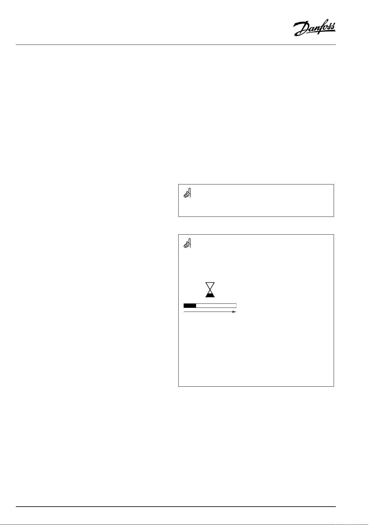
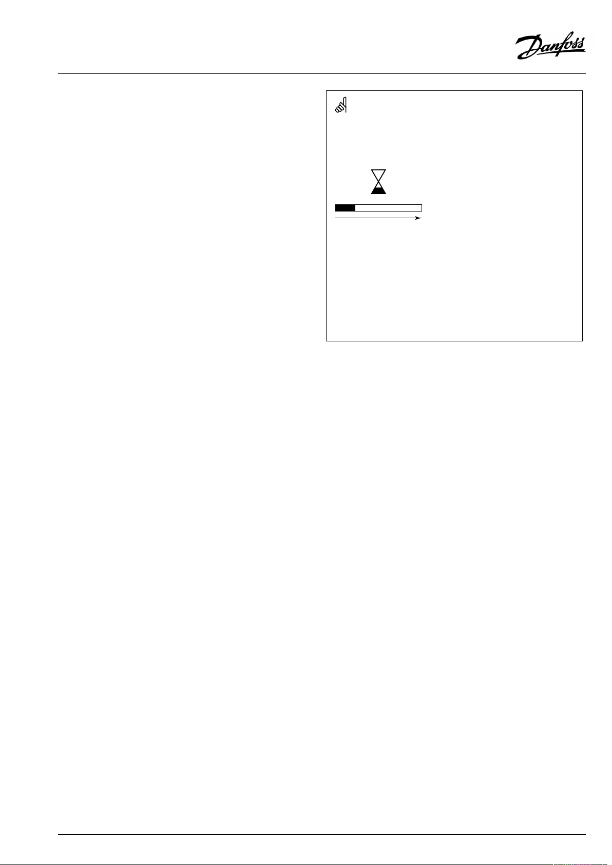
Automaticupdateofcontrollersoftware(firmware):
Thesoftwareofthecontrollerisupdatedautomaticallywhenthekey
isinserted(asofcontrollerversion1.11(ECL210/310)andversion
1.58(ECL296)).Thefollowinganimationwillbeshownwhenthe
softwareisbeingupdated:
Progressbar
Duringupdate:
•DonotremovetheKEY
Ifthekeyisremovedbeforethehour-glassisshown,youhave
tostartafresh.
•Donotdisconnectthepower
Ifthepowerisinterruptedwhenthehour-glassisshown,the
controllerwillnotwork.
•Manualupdateofcontrollersoftware(firmware):
Seethesection"Automatic/manualupdateoffirmware"
2|©Danfoss|2021.03
AQ026486454993en-010401
Page 3
OperatingGuideECLComfort210/310,applicationA267
SafetyNote
Toavoidinjuryofpersonsanddamagestothedevice,itisabsolutely
necessarytoreadandobservetheseinstructionscarefully.
Necessaryassembly,start-up,andmaintenanceworkmustbe
performedbyqualifiedandauthorizedpersonnelonly.
Locallegislationsmustberespected.Thiscomprisesalsocable
dimensionsandtypeofisolation(doubleisolatedat230V).
AfusefortheECLComfortinstallationismax.10Atypically.
TheambienttemperaturerangesforECLComfortinoperationare:
ECLComfort210/310:0-55°C
ECLComfort296:0-45°C.
Exceedingthetemperaturerangecanresultinmalfunctions.
Installationmustbeavoidedifthereisariskforcondensation(dew).
Thewarningsignisusedtoemphasizespecialconditionsthatshould
betakenintoconsideration.
Thissymbolindicatesthatthisparticularpieceofinformationshould
bereadwithspecialattention.
AsthisOperatingGuidecoversseveralsystemtypes,specialsystem
settingswillbemarkedwithasystemtype.Allsystemtypesareshown
inthechapter:'Identifyingyoursystemtype'.
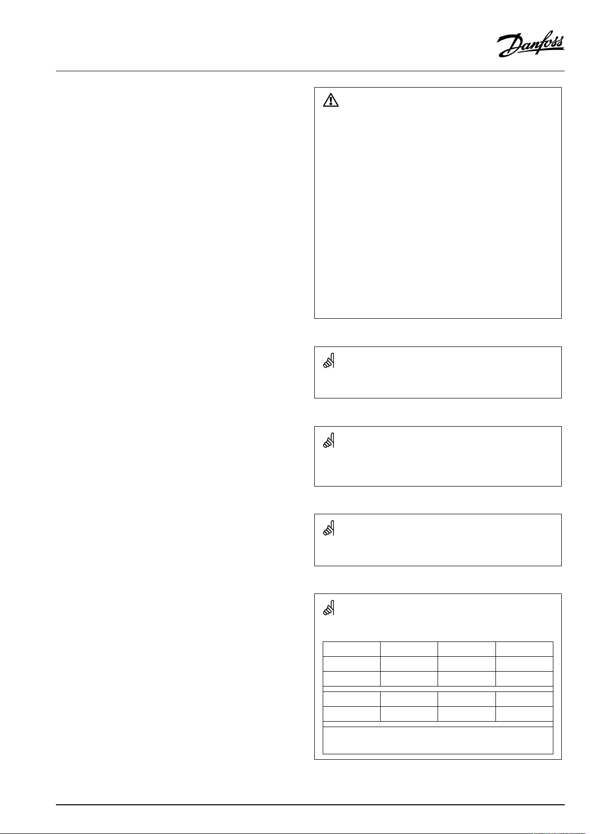
°C(degreesCelsius)isameasuredtemperaturevaluewhereasK
(Kelvin)oftenisusedfortemperaturedifferences.
TheIDno.isuniquefortheselectedparameter.
ExampleFirstdigitSeconddigitLastthreedigits
1117411174
-
Circuit1Parameterno.
12174
IfanIDdescriptionismentionedmorethanonce,itmeansthatthere
arespecialsettingsforoneormoresystemtypes.Itwillbemarked
withthesystemtypeinquestion(e.g.12174-A266.9).
1
-
2
Circuit2Parameterno.
AQ026486454993en-010401
174
©Danfoss|2021.03|3
Page 4
OperatingGuideECLComfort210/310,applicationA267
ParametersindicatedwithanIDno.like"1x607"meanauniversal
parameter.
xstandsforcircuit/parametergroup.
DisposalNote
Thissymbolontheproductindicatesthatitmaynot
bedisposedofashouseholdwaste.
Itmustbehandedovertotheapplicabletake-back
schemefortherecyclingofelectricalandelectronic
equipment.
•Disposeoftheproductthroughchannelsprovided
forthispurpose.
•Complywithalllocalandcurrentlyapplicablelaws
andregulations.
4|©Danfoss|2021.03
AQ026486454993en-010401
Page 5
OperatingGuideECLComfort210/310,applicationA267
2.0Installation
2.1Beforeyoustart
TheapplicationA267isveryflexible.Thesearethebasicprinciples:
Heating(circuit1):
Typically,theflowtemperatureisadjustedaccordingtoyour
requirements.TheflowtemperaturesensorS3isthemost
importantsensor.ThedesiredflowtemperatureatS3iscalculated
intheECLcontroller,basedontheoutdoortemperature(S1).
Thelowertheoutdoortemperature,thehigherthedesiredflow
temperature.Bymeansofaweekschedule(upto3‘Comfort’
periods/day),theheatingcircuit1canbein‘Comfort’or
‘Saving’mode(twodifferenttemperaturevaluesfordesiredroom
temperature).
ThemotorizedcontrolvalveM1isopenedgraduallywhenthe
flowtemperatureislowerthanthedesiredflowtemperatureand
viceversa.
Thereturntemperature(S5)tothedistrictheatingsupplyshould
notbetoohigh.Ifso,thedesiredflowtemperaturecanbeadjusted
(typicallytoalowervalue),thusresultinginagradualclosingofthe
motorizedcontrolvalve.
Furthermore,thereturntemperaturelimitationcandepend
ontheoutdoortemperature.Typically,thelowertheoutdoor
temperature,thehighertheacceptedreturntemperature.
Inboiler-basedheatingsupplythereturntemperatureshouldnot
betoolow(sameadjustmentprocedureasabove).
Ifthemeasuredroomtemperature(S7)doesnotequalthedesired
roomtemperature,thedesiredflowtemperaturecanbeadjusted.
Thecirculationpump(P1)isONatheatdemandoratfrost
protection.Thecirculationpump(P1)canbeswitchedOFF
whenheatingtheDHW(dependentpriority).Ifthesystemhas
achangeovervalve(P2)betweentheheatingandDHWheating
circuit,thecirculationpump(P1)isONwhenheatingtheDHW.
TheheatingcanbeswitchedOFFwhentheoutdoortemperatureis
higherthanaselectablevalue.
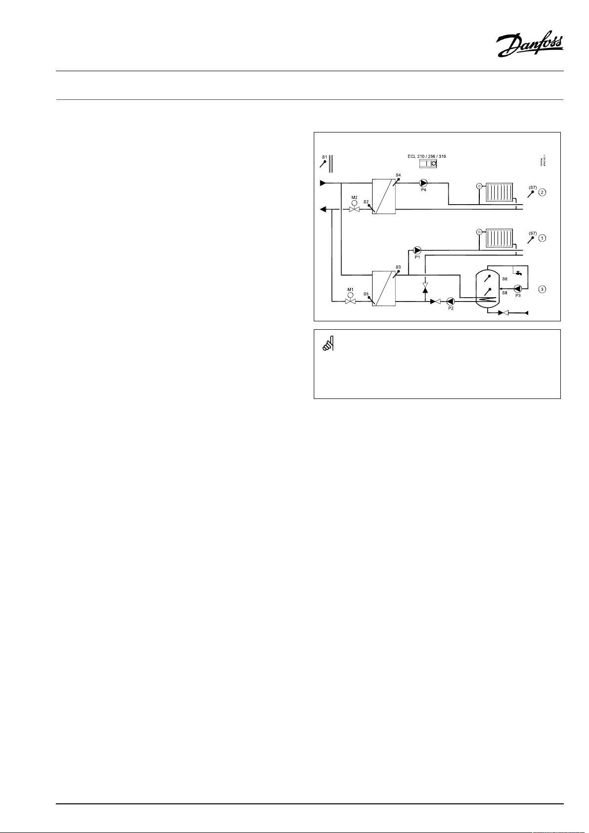
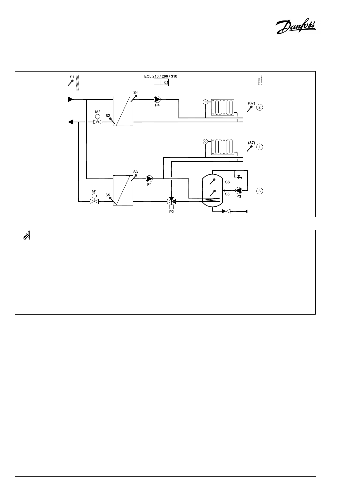
TypicalA267application:
Theshowndiagramisafundamentalandsimplifiedexampleanddoes
notcontainallcomponentsthatarenecessaryinasystem.
AllnamedcomponentsareconnectedtotheECLComfortcontroller.
Listofcomponents:
S1
Outdoortemperaturesensor
S2Returntemperaturesensor,circuit2
S3
Flowtemperaturesensor,circuit1
S4
Flowtemperaturesensor,circuit2
S5Returntemperaturesensor,circuit1
S6
DHWtanktemperaturesensor,upper
S7
Roomtemperaturesensor,circuits1and2
S8
DHWtanktemperaturesensor,lower
P1
Circulationpump,heating,circuit1
P2
DHWheatingpump,circuit3
P3
DHWcirculationpump,circuit3
P4
Circulationpump,heating,circuit2
M1
Motorizedcontrolvalve,circuits1and3
M2
Motorizedcontrolvalve,circuit2
AQ026486454993en-010401
©Danfoss|2021.03|5
Page 6
OperatingGuideECLComfort210/310,applicationA267
Heating(circuit2):
Thiscircuitworksaftersameprinciplesascircuit1.
TheflowtemperaturesensorS4isthemostimportantsensor.
Bymeansofaweekschedule(upto3‘Comfort’periods/day),the
heatingcircuit2canbein‘Comfort’or‘Saving’mode(twodifferent
temperaturevaluesfordesiredroomtemperature).Themotorized
controlvalveM2controlsthecircuit.
Thereturntemperature(S2)enableslimitationasdescribed
previously.
IfthemeasuredroomtemperatureS7doesnotequalthedesired
roomtemperature,thedesiredflowtemperaturecanbeadjusted.
Thecirculationpump(P4)isONatheatdemandoratfrost
protection.
TheheatingcanbeswitchedOFFwhentheoutdoortemperatureis
higherthanaselectablevalue.
Heatingcircuit2canbeconnectedafterheatingcircuit1.Ifso,the
desiredflowtemperatureatS3canbeinfluencedbythedesired
flowtemperatureatS4.
Heatingcircuits1and2:
Theheatingcircuits1and2canusethesameroomtemperature
sensor(S7).However,eachheatingcircuitcanhaveanECA30,
RemoteControlUnit,inordertohaveseparateroomtemperature
signals.Anothersolution:UseS7foroneoftheheatingcircuitsand
ECA30fortheotherheatingcircuit.
A267.1examplea:
A267.1exampleb:
A267.1examplec:
6|©Danfoss|2021.03
AQ026486454993en-010401
Page 7
OperatingGuideECLComfort210/310,applicationA267
DomesticHotWater(DHW ,circuit3):
Bymeansofaweekschedule(upto3Comfortperiods/day),the
DHWcircuitcanbein‘Comfort’or‘Saving’mode(twodifferent
temperaturevaluesfordesiredDHWtemperature).
IfthemeasuredDHWtemperature(S6)islowerthanthedesired
DHWtemperature,theheatingcirculationpump(P1)canbe
switchedOFFandtheDHWheatingpump(P2)isswitchedON.The
motorizedcontrolvalve(M1)iscontrolledinordertomaintainthe
DHWheatingtemperatureatS3.
TheDHWheatingtemperatureistypically10-15degreeshigher
thanthedesiredDHWtemperature.
DHWtankwith1temperaturesensor:
WhenthemeasuredDHWtemperature(S6)getshigherthanthe
desiredDHWtemperature,theDHWheatingpump(P2)isswitched
OFF.Apost-runtimecanbeset.Themotorizedcontrolvalve(M1)
willhereaftermaintainthedesiredflowtemperatureintheheating
circuit.
DHWtankwith2temperaturesensors:
WhenthemeasuredDHWtemperature(S6)getshigherthanthe
desiredDHWtemperatureandthelowertemperature(atS8)gets
higherthanthecut-outtemperature,theDHWheatingpump(P2)
isswitchedOFF.Apost-runtimecanbeset.Themotorizedcontrol
valve(M1)willhereaftermaintainthedesiredflowtemperaturein
theheatingcircuit.
A267.1exampled:
A267.1examplee:
Thecontrollerispre-programmedwithfactorysettingsthatareshown
inthe‘ParameterIDoverview’appendix.
AQ026486454993en-010401
©Danfoss|2021.03|7
Page 8
OperatingGuideECLComfort210/310,applicationA267
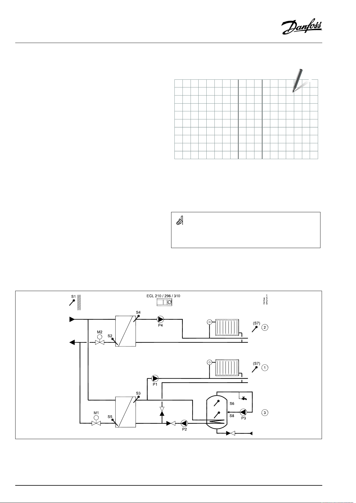
2.2Identifyingthesystemtype
Sketchyourapplication
TheECLComfortcontrollerseriesisdesignedforawiderange
ofheating,domestichot-water(DHW)andcoolingsystemswith
differentconfigurationsandcapacities.Ifyoursystemdiffers
fromthediagramsshownhere,youmaywanttomakeasketch
ofthesystemabouttobeinstalled.Thismakesiteasiertouse
theOperatingGuide,whichwillguideyoustep-by-stepfrom
installationtofinaladjustmentsbeforetheend-usertakesover.
TheECLComfortcontrollerisauniversalcontrollerthatcanbe
usedforvarioussystems.Basedontheshownstandardsystems,
itispossibletoconfigureadditionalsystems.Inthischapteryou
findthemostfrequentlyusedsystems.Ifyoursystemisnotquite
asshownbelow,findthediagramwhichhasthebestresemblance
withyoursystemandmakeyourowncombinations.
SeetheInstallationGuide(deliveredwiththeapplicationkey)for
applicationtypes/sub-types.
Thecirculationpump(s)inheatingcircuit(s)canbeplacedintheflow
aswellasthereturn.Placethepumpaccordingtothemanufacturer’s
specification.
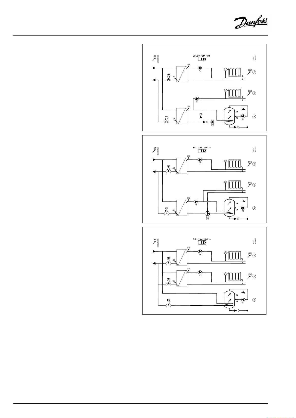
A267.1,examplea
Indirectlyconnectedsystemwith2heatingcircuitsandsecondarilyconnectedDHWtankwithinternalheatexchanger(optionalDHW
priority).
8|©Danfoss|2021.03
AQ026486454993en-010401
Page 9

OperatingGuideECLComfort210/310,applicationA267
SpecialsettingsfortypeA267.1,examplea:
DHWcircuit(circuit3)
TheDHWheatingiscontrolledbymeansofDHWheatingpumpP2.
Navigation:IDno.:
MENU\Settings\Application:'Ch.-o.valve/P'
TheDHWtankisconnectedsecondarily.
MENU\Settings\Application:‘Tank,sec./prim. '
Recommendedsetting:
13051
13053
ON
OFF
AQ026486454993en-010401
©Danfoss|2021.03|9
Page 10
OperatingGuideECLComfort210/310,applicationA267
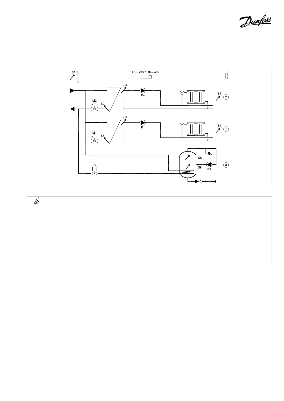
A267.1,exampleb
Indirectlyconnectedsystemwith2heatingcircuitsandsecondarilyconnectedDHWtankwithinternalheatexchanger(DHWpriority).
SpecialsettingsfortypeA267.1,exampleb:
DHWcircuit(circuit3)
TheDHWheatingiscontrolledbymeansofchangeovervalve*P2.
Navigation:IDno.:
MENU\Settings\Application:'Ch.-o.valve/P'
TheDHWtankisconnectedsecondarily.
MENU\Settings\Application:‘Tank,sec./prim. '
*
Thechangeovervalvecanbeofthistype:
DanfossAMZ113
Normalpowersupplied.Whenthecontrolvoltageisapplied(fromterminal12),thechangeovervalvechangesflowdirection.
13051
13053
Recommendedsetting:
OFF
OFF
10|©Danfoss|2021.03
AQ026486454993en-010401
Page 11
OperatingGuideECLComfort210/310,applicationA267
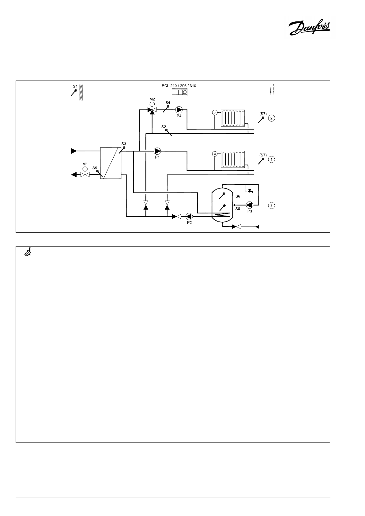
A267.1,examplec
Indirectlyconnectedsystemwith2heatingcircuitsandprimarilyconnectedDHWtankwithinternalheatexchanger(optionalDHW
priority).
SpecialsettingsfortypeA267.1,examplec:
DHWcircuit(circuit3)
TheDHWheatingiscontrolledbymeansofON/OFFvalve*P2.
Navigation:
MENU\Settings\Application:'Ch.-o.valve/P'
TheDHWtankisconnectedsecondarily.
MENU\Settings\Application:‘Tank,sec./prim.
*
Thechangeovervalvecanbeofthistype:
DanfossAMZ113
Normalpowersupplied.Whenthecontrolvoltageisapplied(fromterminal12),thechangeovervalvechangesflowdirection.
IDno.:
13051
13053
Recommendedsetting:
ON
ON
AQ026486454993en-010401
©Danfoss|2021.03|11
Page 12
OperatingGuideECLComfort210/310,applicationA267
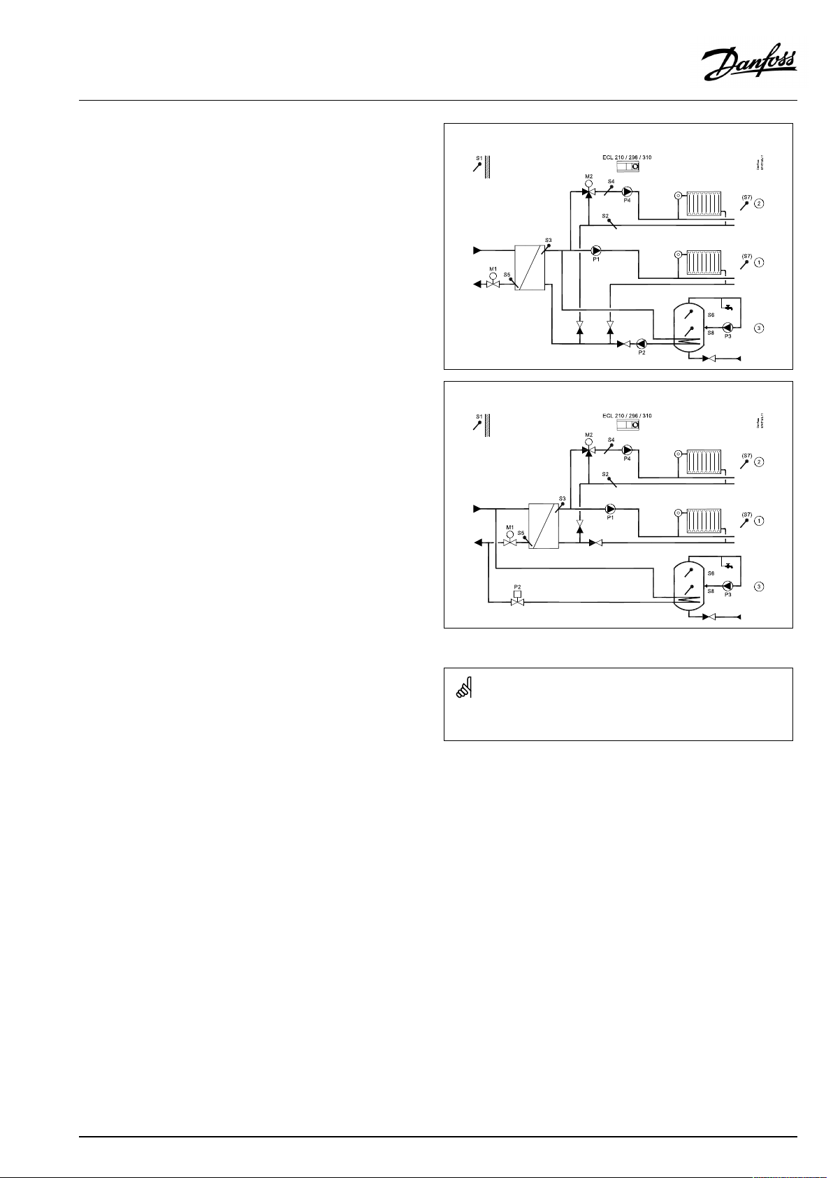
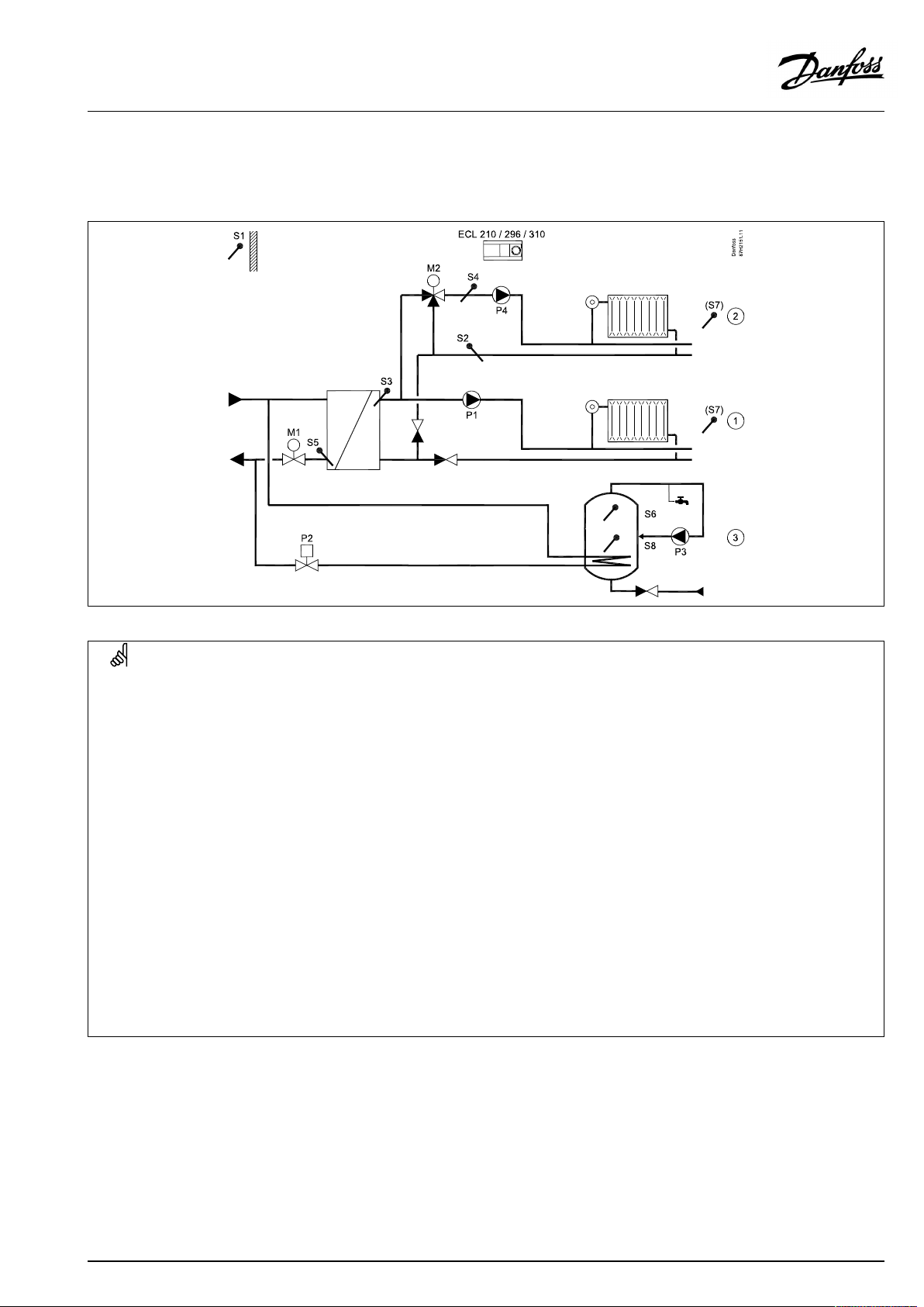
A267.1,exampled
Indirectlyconnectedsystemwith2heatingcircuits(circuit2isconnectedassubcircuit)andsecondarilyconnectedDHWtankwith
internalheatexchanger(optionalDHWpriority).
SpecialsettingsfortypeA267.1,exampled:
Heatingcircuit1
Heatingcircuit1mustreceiveinformationaboutandreactonthedesiredflowtemperaturefromheatingcircuit2.
Navigation:IDno.:
MENU\Settings\Application:'Demandoffset'
*
Thedesiredflowtemperatureinheatingcircuit1is5Kabovethedesiredflowtemperatureinheatingcircuit2.
Heatingcircuit2
Heatingcircuit2isconnectedsecondarilyandmustsendinformationaboutitsdesiredflowtemperaturetoheatingcircuit1.
Navigation:IDno.:
MENU\Settings\Application:'SenddesiredT'
DHWcircuit(circuit3)
TheDHWheatingiscontrolledbymeansofDHWheatingpumpP2.
Navigation:IDno.:
MENU\Settings\Application:'Ch.-o.valve/P'
TheDHWtankisconnectedsecondarily.
MENU\Settings\Application:‘Tank,sec./prim. '
11017
12500
13051
13053
Recommendedsetting:
5K*
Recommendedsetting:
ON
Recommendedsetting:
ON
OFF
12|©Danfoss|2021.03
AQ026486454993en-010401
Page 13
OperatingGuideECLComfort210/310,applicationA267
A267.1,examplee
Indirectlyconnectedsystemwith2heatingcircuits(circuit2isconnectedassubcircuit)andprimarilyconnectedDHWtankwith
internalheatexchanger(optionalDHWpriority).
SpecialsettingsfortypeA267.1,examplee:
Heatingcircuit1
Heatingcircuit1mustreceiveinformationaboutandreactonthedesiredflowtemperaturefromheatingcircuit2.
Navigation:
MENU\Settings\Application:'Demandoffset'
*
Thedesiredflowtemperatureinheatingcircuit1is5Kabovethedesiredflowtemperatureinheatingcircuit2.
Heatingcircuit2
Heatingcircuit2isconnectedsecondarilyandmustsendinformationaboutitsdesiredflowtemperaturetoheatingcircuit1.
Navigation:
MENU\Settings\Application:'SenddesiredT'
DHWcircuit(circuit3)
TheDHWheatingiscontrolledbymeansofON/OFFvalve**P2/M3.
Navigation:
MENU\Settings\Application:'Ch.-o.valve/P'
TheDHWtankisconnectedsecondarily.
MENU\Settings\Application:‘Tank,sec./prim. '
**
Thechangeovervalvecanbeofthistype:
DanfossAMZ113
Normalpowersupplied.Whenthecontrolvoltageisapplied(fromterminal12),thechangeovervalvechangesflowdirection.
IDno.:
11017
IDno.:
12500
IDno.:
13051
13053
Recommendedsetting:
5K*
Recommendedsetting:
ON
Recommendedsetting:
ON
ON
AQ026486454993en-010401
©Danfoss|2021.03|13
Page 14
OperatingGuideECLComfort210/310,applicationA267
2.3Mounting
2.3.1MountingtheECLComfortcontroller
SeetheInstallationGuidewhichisdeliveredtogetherwiththe
ECLComfortcontroller.
Foreasyaccess,youshouldmounttheECLComfortcontrollernear
thesystem.
ECLComfort210/296/310canbemounted
•onawall
•onaDINrail(35mm)
ECLComfort296canbemounted
•inapanelcut-out
ECLComfort210canbemountedinanECLComfort310basepart
(forfutureupgrade).
Screws,PGcableglandsandrawlplugsarenotsupplied.
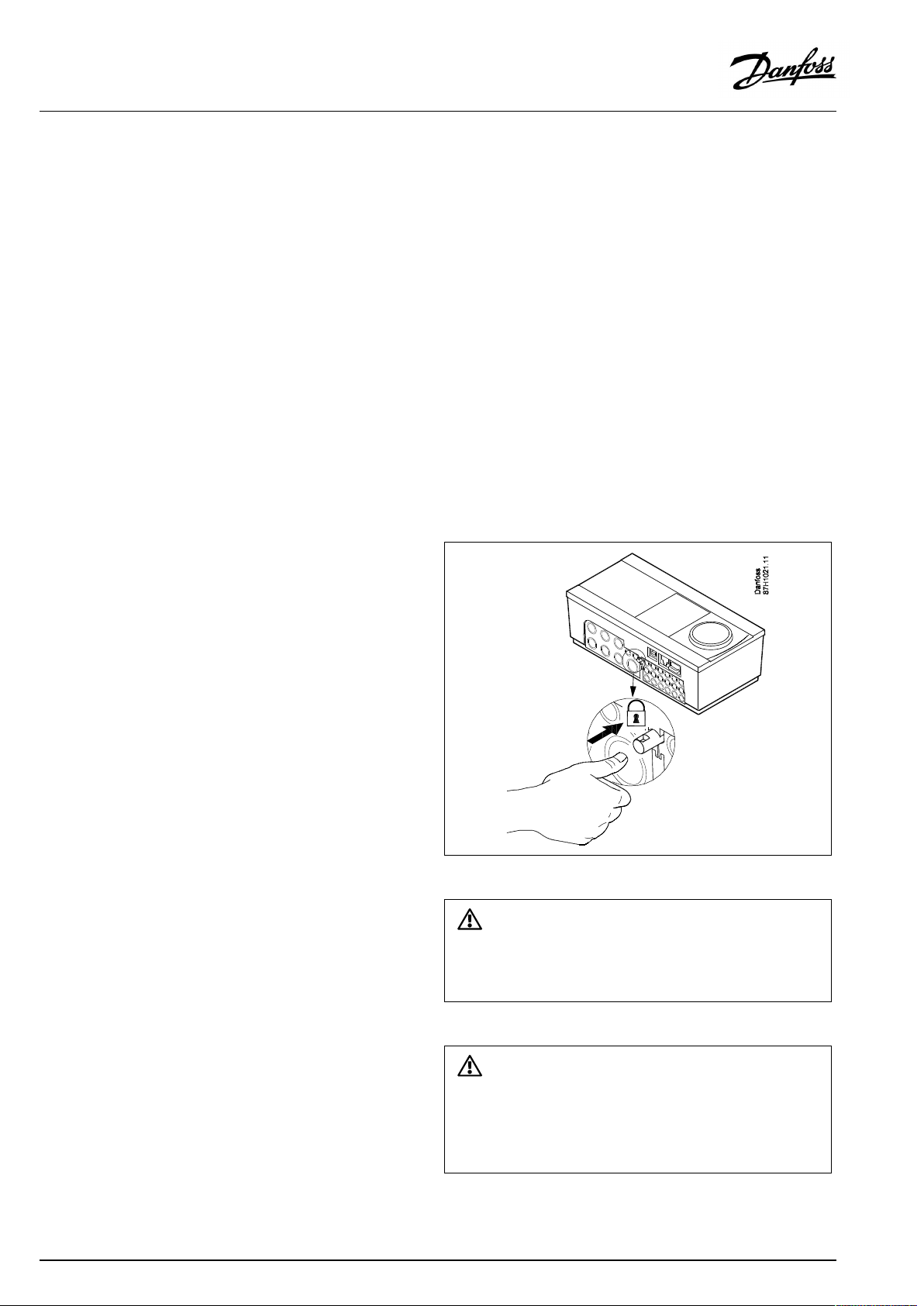
LockingtheECLComfort210/310controller
InordertofastentheECLComfortcontrollertoitsbasepart,secure
thecontrollerwiththelockingpin.
14|©Danfoss|2021.03
Topreventinjuriestopersonsorthecontroller,thecontrollerhasto
besecurelylockedintothebase.Forthispurpose,pressthelocking
pinintothebaseuntilaclickisheardandthecontrollernolonger
canberemovedfromthebase.
Ifthecontrollerisnotsecurelylockedintothebasepart,thereisarisk
thatthecontrollerduringoperationcanunlockfromthebaseandthe
basewithterminals(andalsothe230Va.c.connections)areexposed.
Topreventinjuriestopersons,alwaysmakesurethatthecontroller
issecurelylockedintoitsbase.Ifthisisnotthecase,thecontroller
shouldnotbeoperated!
AQ026486454993en-010401
Page 15
OperatingGuideECLComfort210/310,applicationA267
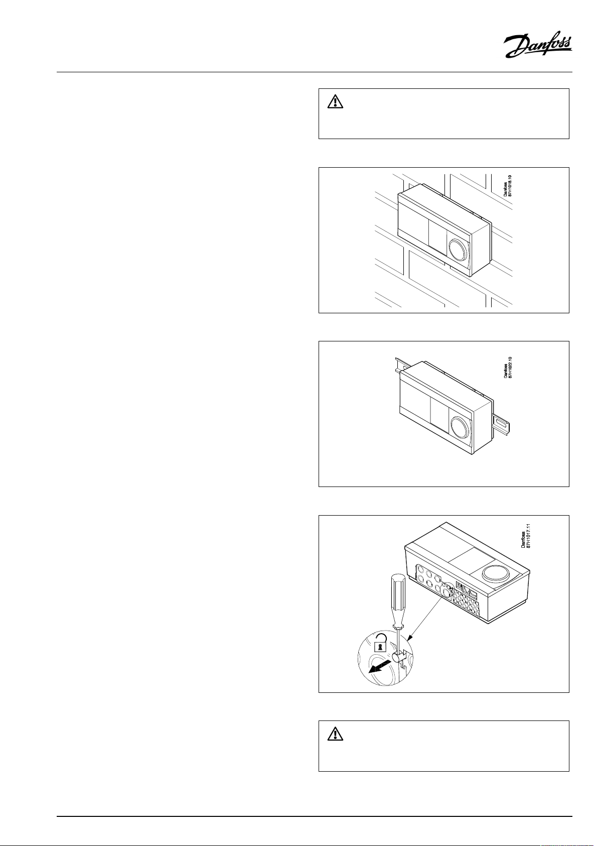
Mountingonawall
Mountthebasepartonawallwithasmoothsurface.Establishthe
electricalconnectionsandpositionthecontrollerinthebasepart.
Securethecontrollerwiththelockingpin.
MountingonaDINrail(35mm)
MountthebasepartonaDINrail.Establishtheelectrical
connectionsandpositionthecontrollerinthebasepart.Secure
thecontrollerwiththelockingpin.
Theeasywaytolockthecontrollertoitsbaseorunlockitistousea
screwdriveraslever.
DismountingtheECLComfortcontroller
Inordertoremovethecontrollerfromthebasepart,pulloutthe
lockingpinbymeansofascrewdriver.Thecontrollercannowbe
removedfromthebasepart.
Theeasywaytolockthecontrollertoitsbaseorunlockitistousea
screwdriveraslever.
AQ026486454993en-010401
©Danfoss|2021.03|15
Page 16
OperatingGuideECLComfort210/310,applicationA267
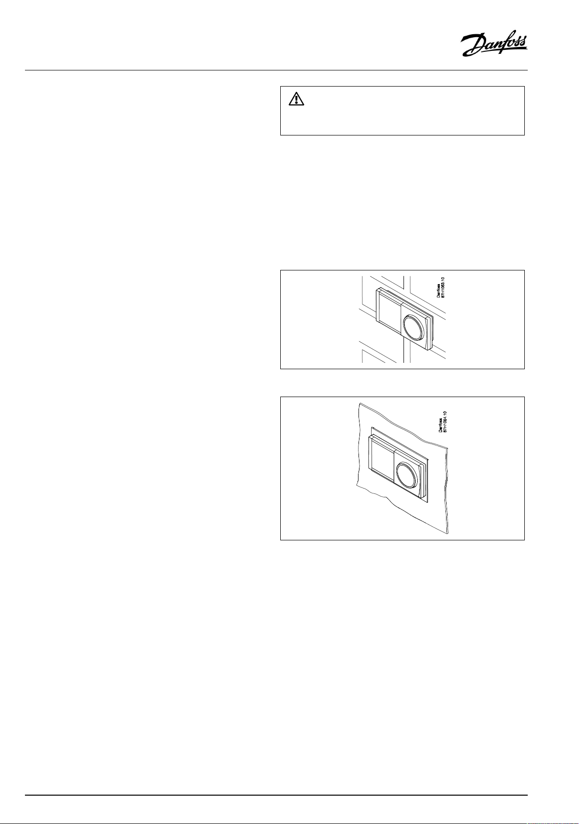
2.3.2MountingtheRemoteControlUnitsECA30/31
Selectoneofthefollowingmethods:
•Mountingonawall,ECA30/31
•Mountinginapanel,ECA30
Screwsandrawlplugsarenotsupplied.
Mountingonawall
MountthebasepartoftheECA30/31onawallwithasmooth
surface.Establishtheelectricalconnections.PlacetheECA30/
31inthebasepart.
BeforeremovingtheECLComfortcontrollerfromthebasepart,ensure
thatthesupplyvoltageisdisconnected.
Mountinginapanel
MounttheECA30inapanelusingtheECA30framekit(ordercode
no.087H3236).Establishtheelectricalconnections.Securethe
framewiththeclamp.PlacetheECA30inthebasepart.TheECA
30canbeconnectedtoanexternalroomtemperaturesensor.
TheECA31mustnotbemountedinapanelifthehumidity
functionistobeused.
16|©Danfoss|2021.03
AQ026486454993en-010401
Page 17
OperatingGuideECLComfort210/310,applicationA267
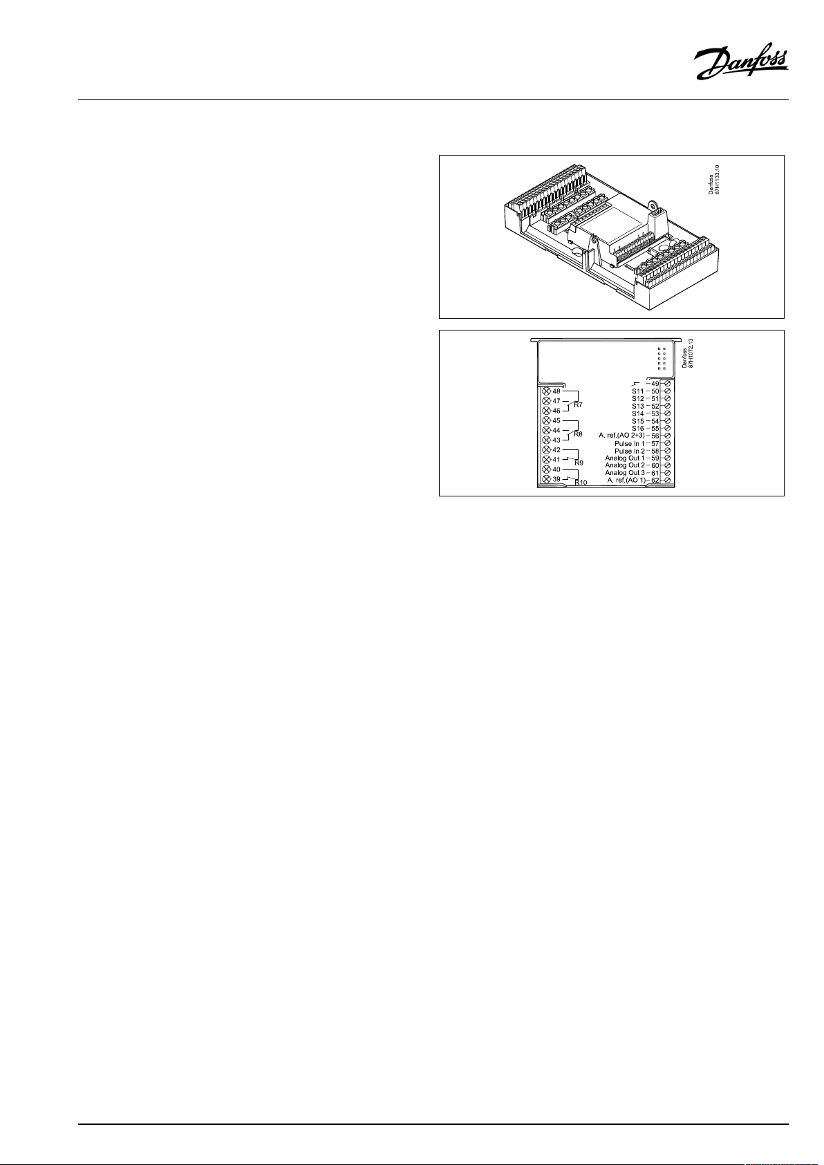
2.3.3MountingtheinternalI/OmoduleECA32
MountingoftheinternalI/OmoduleECA32
TheECA32module(ordercodeno.087H3202)mustbeinserted
intotheECLComfort310/310Bbasepartforadditionalinputand
outputsignalsinrelevantapplications.
TheconnectionbetweentheECLComfort310/310BandECA32
isa10-pole(2x5)connector.Theconnectionisautomatically
establishedwhentheECLComfort310/310Bisplacedonthe
basepart.
AQ026486454993en-010401
©Danfoss|2021.03|17
Page 18
OperatingGuideECLComfort210/310,applicationA267
2.4Placingthetemperaturesensors
2.4.1Placingthetemperaturesensors
Itisimportantthatthesensorsaremountedinthecorrectposition
inyoursystem.
Thetemperaturesensormentionedbelowaresensorsusedforthe
ECLComfort210/296/310serieswhichnotallwillbeneeded
foryourapplication!
Outdoortemperaturesensor(ESMT)
Theoutdoorsensorshouldbemountedonthatsideofthebuilding
whereitislesslikelytobeexposedtodirectsunshine.Itshouldnot
beplacedclosetodoors,windowsorairoutlets.
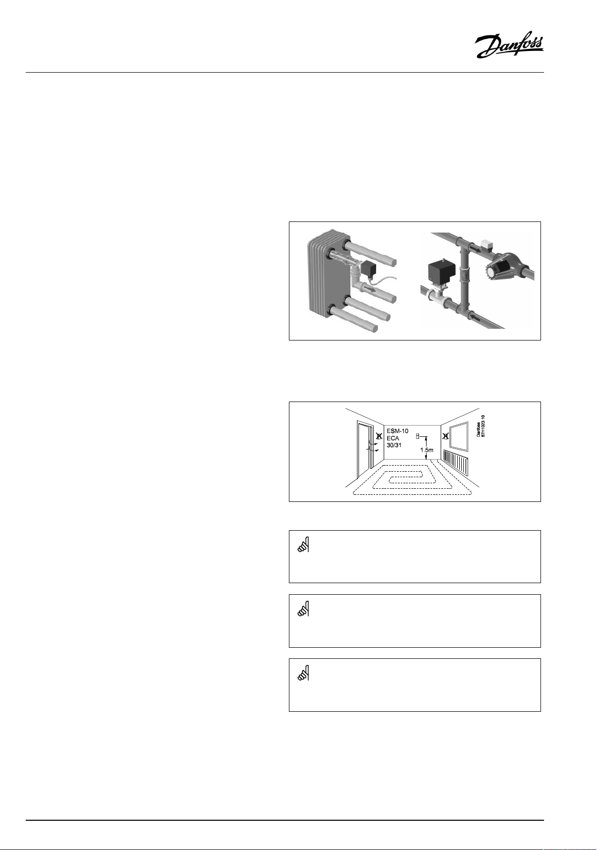
Flowtemperaturesensor(ESMU,ESM-11orESMC)
Placethesensormax.15cmfromthemixingpoint.Insystems
withheatexchanger,DanfossrecommendsthattheESMU-typeto
beinsertedintotheexchangerflowoutlet.
Makesurethatthesurfaceofthepipeiscleanandevenwhere
thesensorismounted.
Returntemperaturesensor(ESMU,ESM-11orESMC)
Thereturntemperaturesensorshouldalwaysbeplacedsothatit
measuresarepresentativereturntemperature.
Roomtemperaturesensor
(ESM-10,ECA30/31RemoteControlUnit)
Placetheroomsensorintheroomwherethetemperatureistobe
controlled.Donotplaceitonoutsidewallsorclosetoradiators,
windowsordoors.
Boilertemperaturesensor(ESMU,ESM-11orESMC)
Placethesensoraccordingtotheboilermanufacturer’s
specification.
Airducttemperaturesensor(ESMB-12orESMUtypes)
Placethesensorsothatitmeasuresarepresentativetemperature.
DHWtemperaturesensor(ESMUorESMB-12)
PlacetheDHWtemperaturesensoraccordingtothemanufacturer’s
specification.
Slabtemperaturesensor(ESMB-12)
Placethesensorinaprotectiontubeintheslab.
ESM-11:Donotmovethesensorafterithasbeenfastenedinorderto
avoiddamagetothesensorelement.
ESM-11,ESMCandESMB-12:Useheatconductingpasteforquick
measurementofthetemperature.
ESMUandESMB-12:Usingasensorpockettoprotectthesensorwill,
however,resultinaslowertemperaturemeasurement.
18|©Danfoss|2021.03
AQ026486454993en-010401
Page 19
OperatingGuideECLComfort210/310,applicationA267
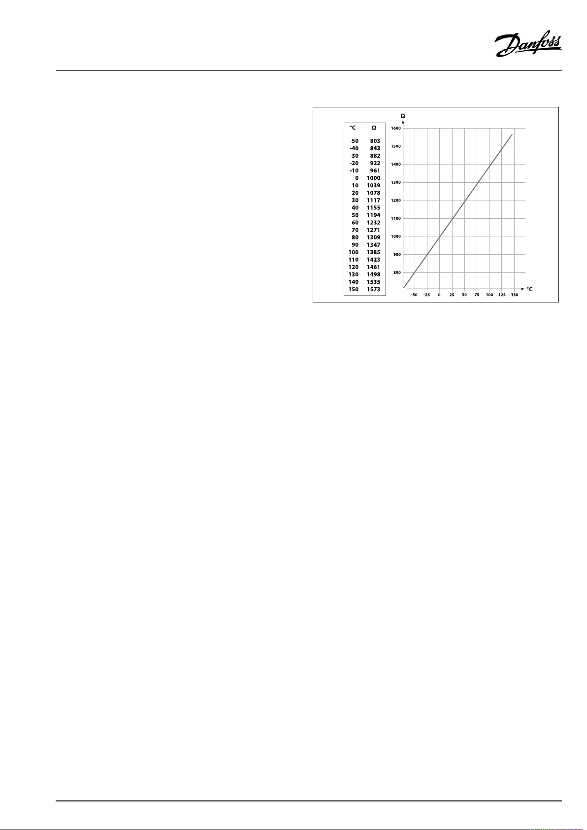
Pt1000temperaturesensor(IEC751B,1000Ω/0°C)
Relationshipbetweentemperatureandohmicvalue:
AQ026486454993en-010401
©Danfoss|2021.03|19
Page 20
OperatingGuideECLComfort210/310,applicationA267
2.5Electricalconnections
2.5.1Electricalconnections230Va.c.
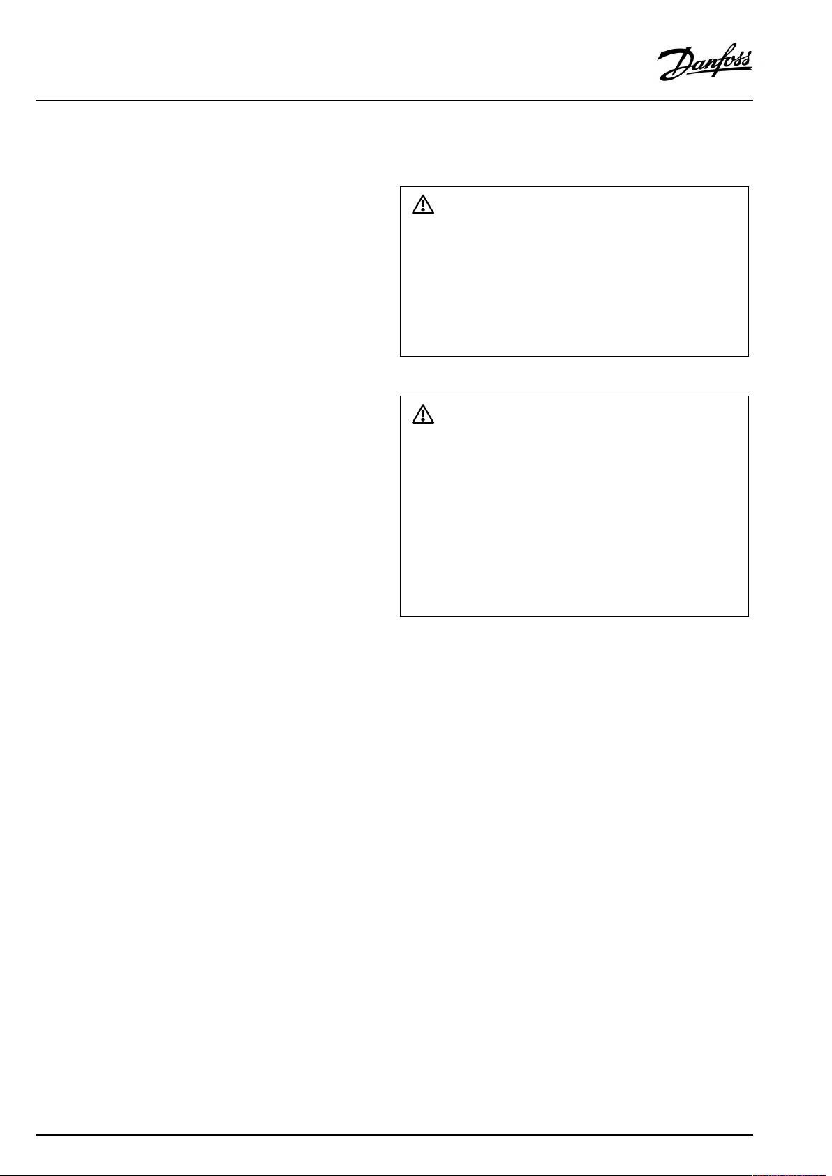
Warning
ElectricconductorsonPCB(PrintedCircuitBoard)forsupplyvoltage,
relaycontactsandtriacoutputsdonothavemutualsafetydistanceof
minimum6mm.Theoutputsarenotallowedtobeusedasgalvanic
separated(voltfree)outputs.
Ifagalvanicseparatedoutputisneeded,anauxiliaryrelayis
recommended.
24Voltcontrolledunits,forexampleactuators,aretobecontrolledby
meansofECLComfort310,24Voltversion.
SafetyNote
Necessaryassembly,start-up,andmaintenanceworkmustbe
performedbyqualifiedandauthorizedpersonnelonly.
Locallegislationsmustberespected.Thiscomprisesalsocablesize
andisolation(reinforcedtype).
AfusefortheECLComfortinstallationismax.10Atypically.
TheambienttemperaturerangefortheECLComfortinoperationis
0-55°C.Exceedingthistemperaturerangecanresultinmalfunctions.
Installationmustbeavoidedifthereisariskforcondensation(dew).
20|©Danfoss|2021.03
AQ026486454993en-010401
Page 21
OperatingGuideECLComfort210/310,applicationA267
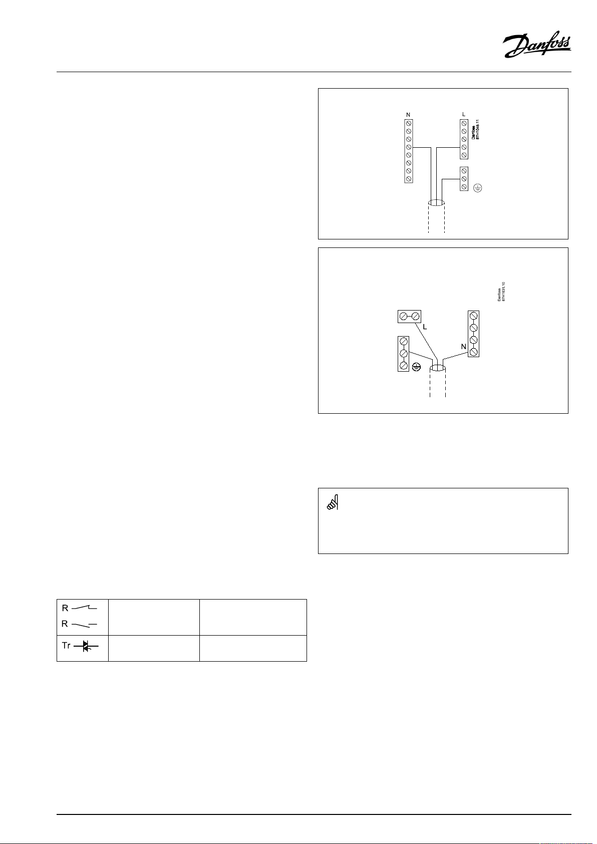
Thecommongroundterminalisusedforconnectionofrelevant
components(pumps,motorizedcontrolvalves).
ECL210/310
ECL296
SeealsotheInstallationGuide(deliveredwiththeapplicationkey)
forapplicationspecificconnections.
Maximumloadratings:
Relayterminals
4(2)A/230Va.c.
(4Aforohmicload,2Afor
inductiveload)
Triac(=electronic
0,2A/230Va.c.
relay)terminals
Wirecrosssection:0.5-1.5mm²
Incorrectconnectioncandamagetheelectronicoutputs.
Max.2x1.5mm²wirescanbeinsertedintoeachscrewterminal.
AQ026486454993en-010401
©Danfoss|2021.03|21
Page 22
OperatingGuideECLComfort210/310,applicationA267
2.5.2Electricalconnections,Pt1000temperaturesensorsandsignals
SeetheInstallationGuide(deliveredwiththeapplicationkey)for
sensorandinputconnections.
A267:
Sen-
Description
sor
S1
Outdoortemperature
Type
(recomm.)
ESMT
sensor*
S2Returntemperaturesensor,
heatingcircuit2
S3
Flowtemperaturesensor,
heatingcircuit1**
S4
Flowtemperaturesensor,
heatingcircuit2**
S5Returntemperaturesensor,
heatingcircuit1
S6
DHWtanktemperature
sensor,upper***
S7Roomtemperature
ESM-11/ESMB/
ESMC/ESMU
ESM-11/ESMB/
ESMC/ESMU
ESM-11/ESMB/
ESMC/ESMU
ESM-11/ESMB/
ESMC/ESMU
ESMB/
ESMU
ESM-10
sensor****,heatingcircuit1
and2
S8
DHWtanktemperature
sensor,lower
*
Iftheoutdoortemperaturesensorisnotconnectedorthe
ESMB/
ESMU
cableisshort-circuited,thecontrollerassumesthatthe
outdoortemperatureis0(zero)°C.Theoutdoortemperature
sensoriscommonforbothheatingcircuits.
**
Theflowtemperaturesensormustalwaysbeconnected
inordertohavethedesiredfunctionality.Ifthesensoris
notconnectedorthecableisshort-circuited,themotorized
controlvalvecloses(safetyfunction).
***
Thissensorisusedifonlyonetanktemperaturesensoris
required.
****
Onlyforroomtemperaturesensorconnection.Theroom
temperaturesignalcanalternativelybeavailablefroma
RemoteControlUnit(ECA30/31).See'Electricalconnections,
ECA30/31'.
22|©Danfoss|2021.03
Wirecrosssectionforsensorconnections:Min.0.4mm².
Totalcablelength:Max.200m(allsensorsincl.internalECL485
communicationbus).
Cablelengthsofmorethan200mmaycausenoisesensibility(EMC).
AQ026486454993en-010401
Page 23
OperatingGuideECLComfort210/310,applicationA267
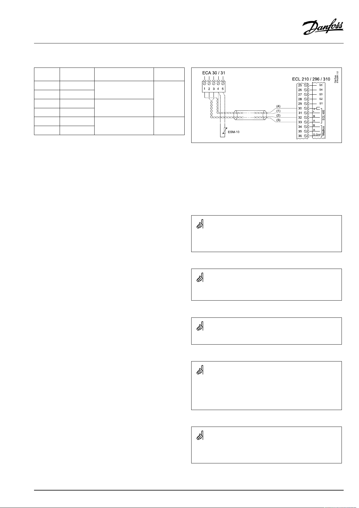
2.5.3Electricalconnections,ECA30/31
Terminal
ECL
Terminal
ECA30/31
30
31
4
1
322
333
4
5
*
Afteranexternalroomtemperaturesensorhasbeenconnected,
Description
Twistedpair
Twistedpair
Ext.roomtemperature
sensor*
Type
(recomm.)
Cable2x
twistedpair
ESM-10
ECA30/31mustberepowered.
ThecommunicationtotheECA30/31mustbesetupintheECL
Comfortcontrollerin'ECAaddr.'
TheECA30/31mustbesetupaccordingly.
AfterapplicationsetuptheECA30/31isreadyafter2–5min.A
progressbarintheECA30/31isdisplayed.
Iftheactualapplicationcontainstwoheatingcircuits,itispossible
toconnectanECA30/31toeachcircuit.Theelectricalconnections
aredoneinparallel.
Max.2ECA30/31canbeconnectedtoanECLComfort310controller
ortoECLComfort210/296/310controllersinamaster-slavesystem.
SetupproceduresforECA30/31:Seesection‘Miscellaneous’ .
ECAinformationmessage:
‘Applicationreq.newerECA’:
Thesoftware(firmware)ofyourECAdoesnotcomplywiththe
software(firmware)ofyourECLComfortcontroller.Pleasecontact
yourDanfosssalesoffice.
Someapplicationsdonotcontainfunctionsrelatedtoactualroom
temperature.TheconnectedECA30/31willonlyfunctionasremote
control.
AQ026486454993en-010401
©Danfoss|2021.03|23
Page 24
OperatingGuideECLComfort210/310,applicationA267
2.5.4Electricalconnections,master/slavesystems
Thecontrollercanbeusedasmasterorslaveinmaster/slave
systemsviatheinternalECL485communicationbus(2xtwisted
paircable).
TheECL485communicationbusisnotcompatiblewiththeECL
businECLComfort110,200,300and301!
Totalcablelength:Max.200m(allsensorsincl.internalECL485
communicationbus).
Cablelengthsofmorethan200mmaycausenoisesensibility(EMC).
Terminal
Description
Type
(recomm.)
30
Commonterminal
+12V*,ECL485communicationbus
31
*OnlyforECA30/31andmaster/
slavecommunication
32
B,ECL485communicationbus
33
A,ECL485communicationbus
Cable2x
twistedpair
ECL485buscable
MaximumrecommendedlengthoftheECL485busiscalculatedlike
this:
Subtract"TotallengthofallinputcablesofallECLcontrollersinthe
master-slavesystem"from200m.
Simpleexamplefortotallengthofallinputcables,3xECL:
1xECL
3xECL
3xECLReturntemp.sensor:
3xECLRoomtemp.sensor:
Total:
Outdoortemp.sensor:
Flowtemp.sensor:
15m
18m
18m
30m
81m
2.5.5Electricalconnections,communication
Electricalconnections,Modbus
ECLComfort210:Non-galvanicisolatedModbusconnections
ECLComfort296:GalvanicisolatedModbusconnections
ECLComfort310:GalvanicisolatedModbusconnections
24|©Danfoss|2021.03
MaximumrecommendedlengthoftheECL485bus:
200-81m=119m
AQ026486454993en-010401
Page 25

OperatingGuideECLComfort210/310,applicationA267
2.5.6Electricalconnections,communication
Electricalconnections,M-bus
ECLComfort210:Notimplemented
ECLComfort296:Onboard,non-galvanicisolated.Max.cable
length50m.
ECLComfort310:Onboard,non-galvanicisolated.Max.cable
length50m.
AQ026486454993en-010401
©Danfoss|2021.03|25
Page 26
OperatingGuideECLComfort210/310,applicationA267
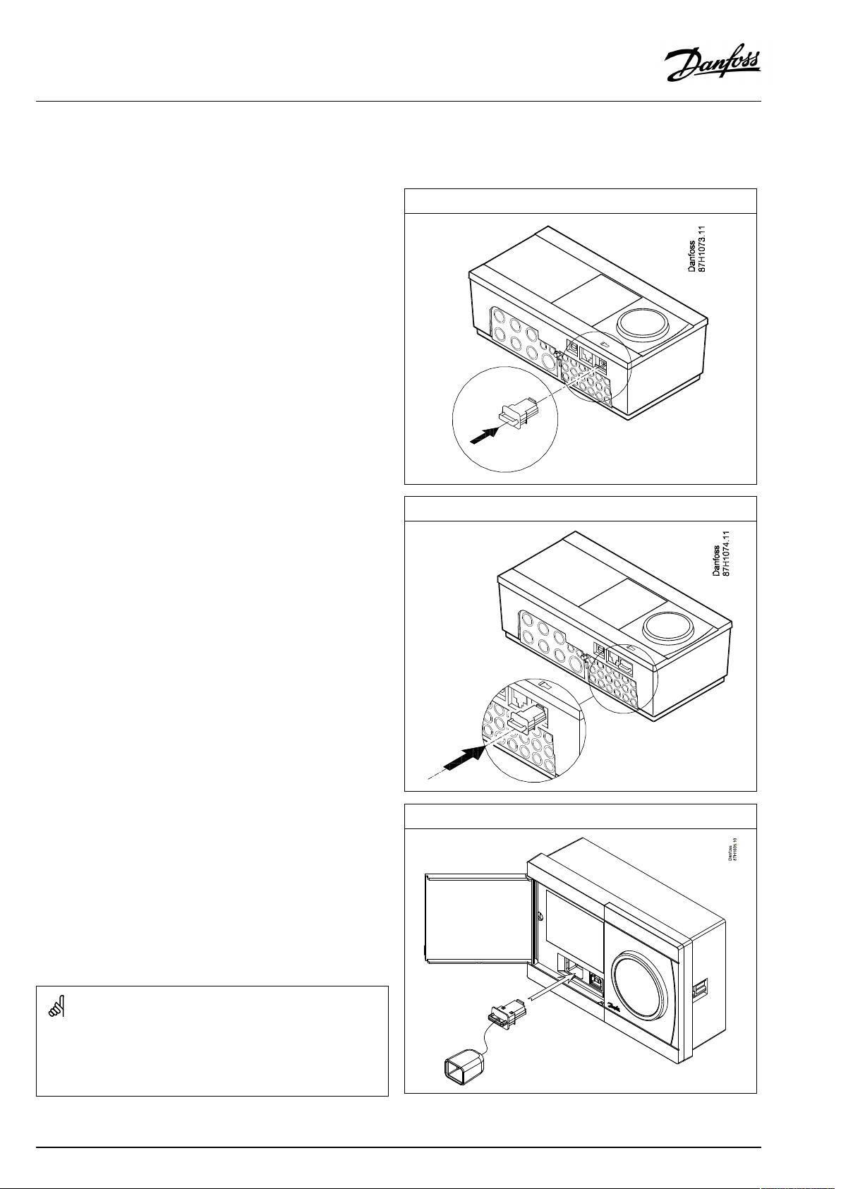
2.6InsertingtheECLApplicationKey
2.6.1InsertingtheECLApplicationKey
TheECLApplicationKeycontains
•theapplicationanditssubtypes,
•currentlyavailablelanguages,
•factorysettings:e.g.schedules,desiredtemperatures,
limitationvaluesetc.Itisalwayspossibletorecoverthefactory
settings,
•memoryforusersettings:specialuser/systemsettings.
Afterhavingpowered-upthecontroller,differentsituationsmight
beexisting:
1.Thecontrollerisnewfromthefactory,theECLApplicationKey
isnotinserted.
2.Thecontrolleralreadyrunsanapplication.TheECLApplication
Keyisinserted,buttheapplicationneedstobechanged.
3.Acopyofthecontrollerssettingsisneededforconfiguring
anothercontroller.
ECLComfort210/310
ECLComfort210/310
Usersettingsare,amongothers,desiredroomtemperature,desired
DHWtemperature,schedules,heatcurve,limitationvaluesetc.
Systemsettingsare,amongothers,communicationset-up,display
brightnessetc.
26|©Danfoss|2021.03
ECLComfort296
AQ026486454993en-010401
Page 27
OperatingGuideECLComfort210/310,applicationA267
Automaticupdateofcontrollersoftware(firmware):
Thesoftwareofthecontrollerisupdatedautomaticallywhenthekey
isinserted(asofcontrollerversion1.11(ECL210/310)andversion
1.58(ECL296)).Thefollowinganimationwillbeshownwhenthe
softwareisbeingupdated:
Progressbar
Duringupdate:
•DonotremovetheKEY
Ifthekeyisremovedbeforethehour-glassisshown,youhave
tostartafresh.
•Donotdisconnectthepower
Ifthepowerisinterruptedwhenthehour-glassisshown,the
controllerwillnotwork.
•Manualupdateofcontrollersoftware(firmware):
Seethesection"Automatic/manualupdateoffirmware"
AQ026486454993en-010401
©Danfoss|2021.03|27
Page 28
OperatingGuideECLComfort210/310,applicationA267
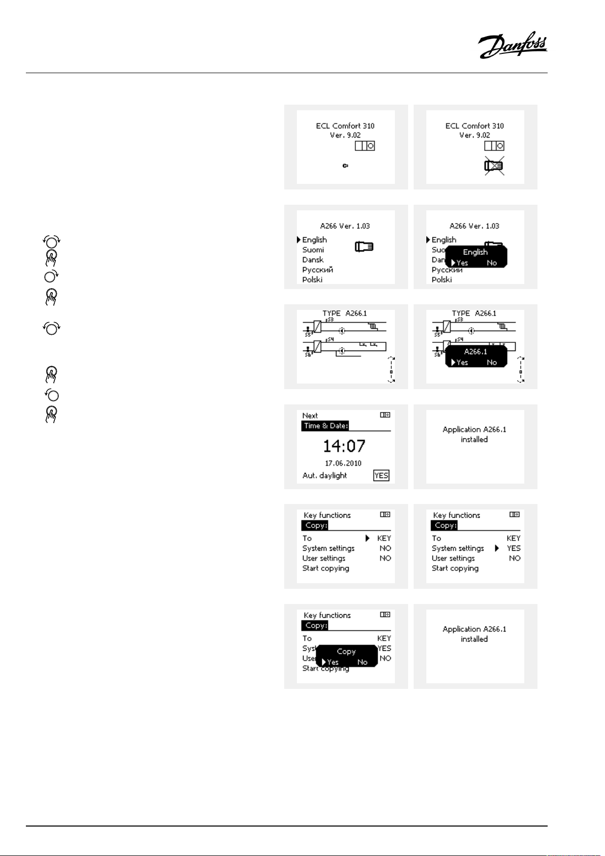
ApplicationKey:Situation1
Thecontrollerisnewfromthefactory,theECLApplicationKey
isnotinserted.
AnanimationfortheECLApplicationKeyinsertionisdisplayed.
InserttheApplicationKey.
ApplicationKeynameandVersionisindicated(example:A266
Ver.1.03).
IftheECLApplicationKeyisnotsuitableforthecontroller,a"cross"
isdisplayedovertheECLApplicationKey-symbol.
Action:Purpose:
Selectlanguage
Confirm
Selectapplication(subtype)
Somekeyshaveonlyoneapplication.
Confirmwith‘Yes’
Set'Time&Date'
Turnandpushthedialtoselectand
change'Hours' ,'Minutes','Date',
'Month'and'Year' .
Choose''Next'
Confirmwith‘Yes’
Goto‘Aut.daylight’
Choosewhether‘ Aut.daylight´*
shouldbeactiveornot
*‘Aut.daylight’istheautomaticchangeoverbetweensummer
andwintertime.
DependingonthecontentsoftheECLApplicationKey,procedure
AorBistakingplace:
A
TheECLApplicationkeycontainsfactorysettings:
Thecontrollerreads/transfersdatafromtheECLApplicationKey
toECLcontroller.
Examples:
YESorNO
Theapplicationisinstalled,andthecontrollerresetsandstartsup.
B
TheECLApplicationkeycontainschangedsystemsettings:
Pushthedialrepeatedly.
’NO’:
’YES*:
Ifthekeycontainsusersettings:
Pushthedialrepeatedly.
‘NO:
‘YES*:
*If‘YES’cannotbechosen,theECLApplicationKeydoesnot
containanyspecialsettings.
Choose‘Startcopying’andconfirmwith'Yes'.
28|©Danfoss|2021.03
OnlyfactorysettingsfromtheECLApplicationKeywill
becopiedtothecontroller.
Specialsystemsettings(differingfromthefactory
settings)willbecopiedtothecontroller.
OnlyfactorysettingsfromtheECLApplicationKeywill
becopiedtothecontroller.
Specialusersettings(differingfromthefactorysettings)
willbecopiedtothecontroller.
AQ026486454993en-010401
Page 29
OperatingGuideECLComfort210/310,applicationA267
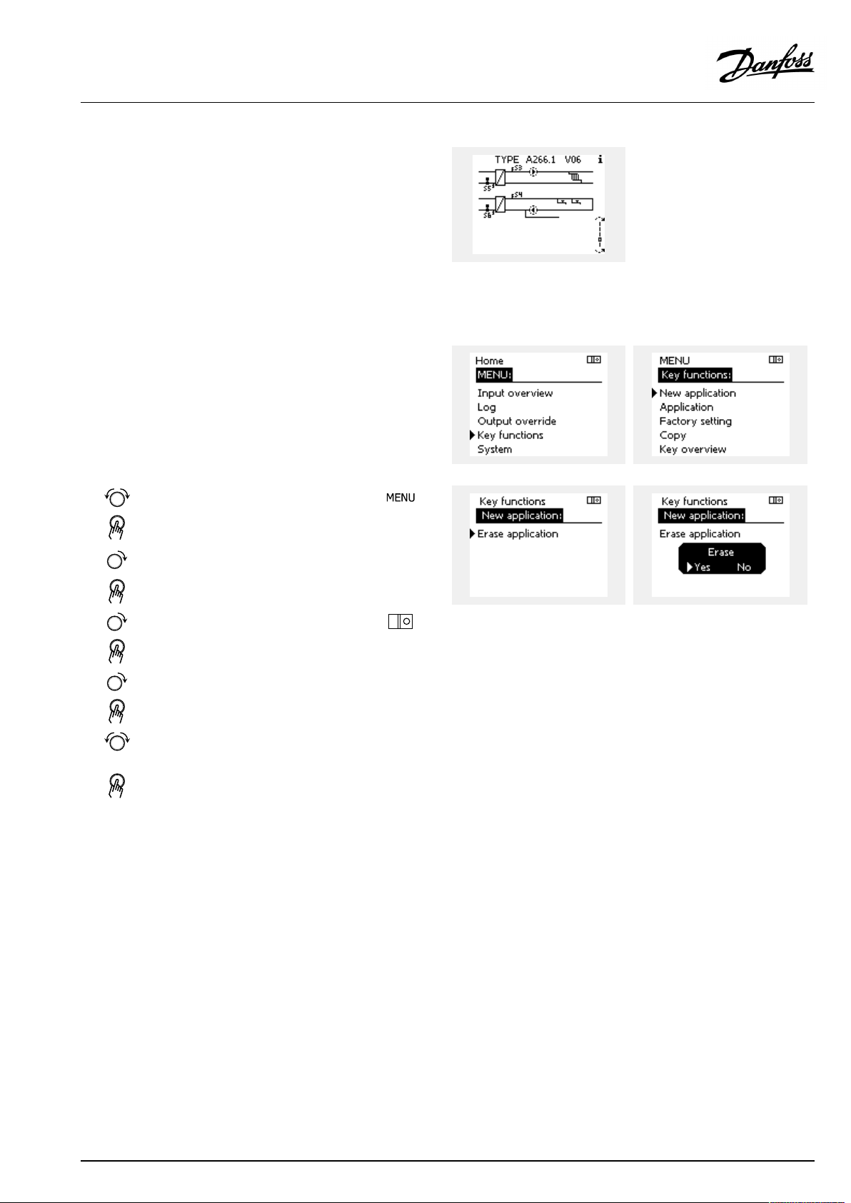
(Example):
The"i"intheupperrightcornerindicatesthat-besidesthefactory
settings-thesubtypealsocontainsspecialuser/systemssettings.
ApplicationKey:Situation2
Thecontrolleralreadyrunsanapplication.TheECLApplication
Keyisinserted,buttheapplicationneedstobechanged.
TochangetoanotherapplicationontheECLApplicationKey,the
currentapplicationinthecontrollermustbeerased(deleted).
BeawarethattheApplicationKeymustbeinserted.
Action:Purpose:
Choose‘MENU’inanycircuit
Confirm
Choosethecircuitselectoratthetop
rightcornerinthedisplay
Confirm
Choose‘Commoncontrollersettings’
Confirm
Choose‘Keyfunctions’
Confirm
Choose‘Eraseapplication’
Confirmwith‘Yes’
Thecontrollerresetsandisreadytobeconfigured.
Followtheproceduredescribedinsituation1.
Examples:
AQ026486454993en-010401
©Danfoss|2021.03|29
Page 30
OperatingGuideECLComfort210/310,applicationA267
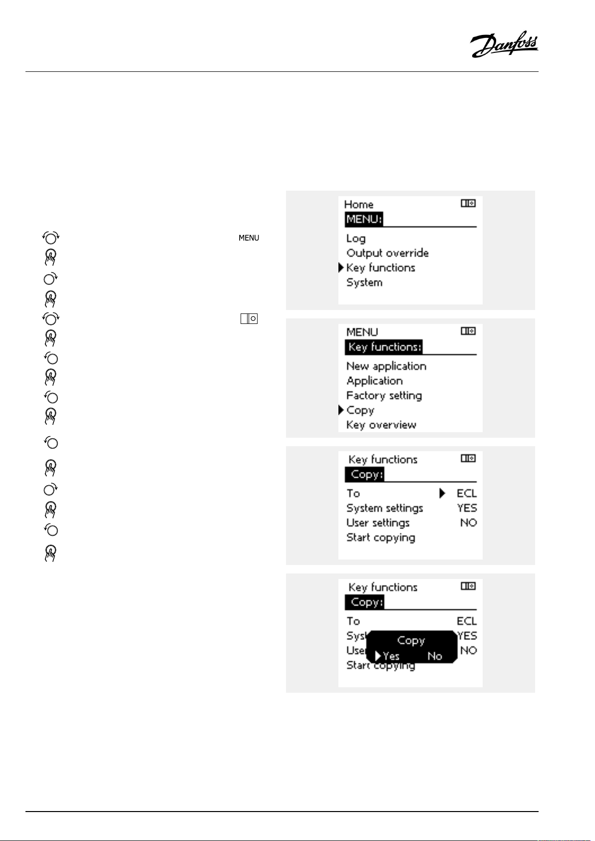
ApplicationKey:Situation3
Acopyofthecontrollerssettingsisneededforconfiguring
anothercontroller.
Thisfunctionisused
•forsaving(backup)ofspecialuserandsystemsettings
•whenanotherECLComfortcontrollerofthesametype(210,
296or310)mustbeconfiguredwiththesameapplicationbut
user/systemsettingsdifferfromthefactorysettings.
HowtocopytoanotherECLComfortcontroller:
Action:Purpose:
Choose‘MENU’
Confirm
Choosethecircuitselectoratthetop
rightcornerinthedisplay
Confirm
Choose'Commoncontrollersettings'
Confirm
Goto‘Keyfunctions’
Confirm
Choose‘Copy’
Confirm
Choose‘To’ .
‘ECL’or‘KEY’willbeindicated.Choose
’ECL’orKEY’
Pushthedialrepeatedlytochoose
copydirection
Choose‘Systemsettings’or‘User
settings’
Pushthedialrepeatedlytochoose
‘Yes’or‘No’in‘Copy’ .Pushtoconfirm.
Choose‘Startcopying’
TheApplicationKeyorthecontroller
isupdatedwithspecialsystemoruser
settings.
Examples:
*
’ECL’or‘KEY’ .
**
‘NO’or‘YES’
*
‘ECL’:
‘KEY’:
**
‘NO’:
‘YES’:
30|©Danfoss|2021.03
DatawillbecopiedfromtheApplicationKeytothe
ECLController.
DatawillbecopiedfromtheECLControllertothe
ApplicationKey.
ThesettingsfromtheECLcontrollerwillnotbecopied
totheApplicationKeyortotheECLComfortcontroller.
Specialsettings(differingfromthefactorysettings)will
becopiedtotheApplicationKeyortotheECLComfort
controller.IfYEScannotbechosen,therearenospecial
settingstobecopied.
AQ026486454993en-010401
Page 31

OperatingGuideECLComfort210/310,applicationA267
Language
Atapplicationupload,alanguagemustbeselected.*
IfanotherlanguagethanEnglishisselected,theselectedlanguage
ANDEnglishwillbeuploadedintotheECLcontroller.
ThismakesserviceeasyforEnglishspeakingservicepeople,just
becausetheEnglishlanguagemenuscanbevisiblebychanging
theactualsetlanguageintoEnglish.
(Navigation:MENU>Commoncontroller>System>Language)
Iftheuploadedlanguageisnotsuitable,theapplicationmustbe
erased.UserandSystemsettingscanbesavedontheapplication
keybeforeerasing.
Afternewuploadwithpreferredlanguage,theexistingUserand
Systemsettingscanbeuploaded.
*)
(ECLComfort310,24Volt)Iflanguagecannotbeselected,the
powersupplyisnota.c.(alternatingcurrent).
2.6.2ECLApplicationKey,copyingdata
Generalprinciples
Whenthecontrollerisconnectedandoperating,youcancheck
andadjustallorsomeofthebasicsettings.Thenewsettingscan
bestoredontheKey.
Factorysettingscanalwaysberestored.
HowtoupdatetheECLApplicationKeyaftersettingshave
beenchanged?
AllnewsettingscanbestoredontheECLApplicationKey.
Howtostorefactorysettinginthecontrollerfromthe
ApplicationKey?
PleasereadtheparagraphconcerningApplicationKey,Situation
1:Thecontrollerisnewfromthefactory,theECLApplicationKey
isnotinserted.
HowtostorepersonalsettingsfromthecontrollertotheKey?
PleasereadtheparagraphconcerningApplicationKey,Situation3:
Acopyofthecontrollerssettingsisneededforconfiguringanother
controller
Asamainrule,theECLApplicationKeyshouldalwaysremainin
thecontroller.IftheKeyisremoved,itisnotpossibletochange
settings.
Makeanoteofnewsettingsinthe'Settingsoverview'table.
DonotremovetheECLApplicationKeywhilecopying.Thedataon
theECLApplicationKeycanbedamaged!
ItispossibletocopysettingsfromoneECLComfortcontrollerto
anothercontrollerprovidedthatthetwocontrollersarefromthesame
series(210or310).
Furthermore,whentheECLComfortcontrollerhasbeenuploaded
withanapplicationkey,minimumversion2.44,itispossibletoupload
personalsettingsfromapplicationkeys,minimumversion2.14.
AQ026486454993en-010401
©Danfoss|2021.03|31
Page 32

OperatingGuideECLComfort210/310,applicationA267
The“Keyoverview”doesnotinform—throughECA30/31—about
thesubtypesoftheapplicationkey.
Keyinserted/notinserted,description:
ECLComfort210/310,controllerversionslowerthan1.36:
-
Takeouttheapplicationkey;for20minutes
settingscanbechanged.
-
Powerupthecontrollerwithoutthe
applicationkeyinserted;for20minutes
settingscanbechanged.
ECLComfort210/310,controllerversions1.36andup:
-
Takeouttheapplicationkey;for20minutes
settingscanbechanged.
-
Powerupthecontrollerwithoutthe
applicationkeyinserted;settingscannotbe
changed.
ECLComfort296,controllerversions1.58andup:
-
Takeouttheapplicationkey;for20minutes
settingscanbechanged.
-
Powerupthecontrollerwithoutthe
applicationkeyinserted;settingscannotbe
changed.
32|©Danfoss|2021.03
AQ026486454993en-010401
Page 33

OperatingGuideECLComfort210/310,applicationA267
2.7Checklist
IstheECLComfortcontrollerreadyforuse?
Makesurethatthecorrectpowersupplyisconnectedtoterminals9and10(230Vor24V).
Makesurethecorrectphaseconditionsareconnected:
230V:Live=terminal9andNeutral=terminal10
24V:SP=terminal9andSN=terminal10
Checkthattherequiredcontrolledcomponents(actuator,pumpetc.)areconnectedtothecorrectterminals.
Checkthatallsensors/signalsareconnectedtothecorrectterminals(see'Electricalconnections').
Mountthecontrollerandswitchonthepower.
IstheECLApplicationKeyinserted(see'InsertingtheApplicationKey').
DoestheECLComfortcontrollercontainanexistingapplication(see'InsertingtheApplicationKey').
Isthecorrectlanguagechosen(see'Language'in'Commoncontrollersettings').
Isthetime&datesetcorrectly(see'Time&Date'in'Commoncontrollersettings').
Istherightapplicationchosen(see'Identifyingthesystemtype').
Checkthatallsettingsinthecontroller(see'Settingsoverview')aresetorthatthefactorysettingscomplywithyour
requirements.
Choosemanualoperation(see'Manualcontrol').Checkthatvalvesopenandclose,andthatrequiredcontrolled
components(pumpetc.)startandstopwhenoperatedmanually.
Checkthatthetemperatures/signalsshowninthedisplaymatchtheactualconnectedcomponents.
Havingcompletedthemanualoperationcheck,choosecontrollermode(scheduled,comfort,savingorfrostprotection).
AQ026486454993en-010401
©Danfoss|2021.03|33
Page 34

OperatingGuideECLComfort210/310,applicationA267
2.8Navigation,ECLApplicationKeyA267
Navigation,A267,circuits1,2and3
Home
MENU
Schedule
Schedulecirc.P
Settings
Flowtemperature
Tanktemperature
Roomlimit
Returnlimit
Optimization
Controlpar.
ApplicationA267
IDnos.
1117812178
11177
1118212182Infl.-max.((
1118312183
1101512015
1103112031
1103212032
1103312033
1103412034
1103512035
1103612036
1103712037
1108512085
1101112011
1101212012
1101312013
1101412014
1102612026
1102012020
1102112021
1117912179
11043
11174
1118412184
1118512185
1118612186
1118712187
1118912189
12177
13193
13195
13194
13152
13030
12174
FunctionCircuit1Circuit2Circuit3
(((
Heatcurve
Temp.max.
Temp.min.
Chargedifference
Startdifference
Stopdifference
Max.chargeT
Infl.-min.
Adapt.time
Limit
HighToutX1
LowlimitY1
LowToutX2
HighlimitY2
Infl.-max.
Infl.-min.
Adapt.time
Priority
Autosaving
Boost
Ramp
Optimizer
Prestop
Basedon
Totalstop
Cut-out
Paralleloperation
Motorpr.
Xp
Tn
Mrun
Nz
Min.act.time
((
((
((
((
((
((
((
((
((
((
((
((
((
((
((
((
((
((
((
((
((
(
((
((
((
((
((
((
(
(
(
(
(
(
34|©Danfoss|2021.03
AQ026486454993en-010401
Page 35

OperatingGuideECLComfort210/310,applicationA267
Navigation,A267.1,circuits1,2and3,continued
Home
MENU
Settings
Holiday
InfluenceoverviewDes.flowT
Application
Anti-bacteria
Des.DHWT
IDnos.
1101012010
11017
11050
1150012500
1102212022
1102312023
1105212052
1107712077
1107812078
1104012040
110931209313093
11141
111421214213142
1214113141
ApplicationA267
FunctionCircuit1Circuit2Circuit3
ECAaddr.
Demandoffset
Pdemand
SenddesiredT
Pexercise
Mexercise
DHWpriority
PfrostT
PheatT
Ppost-run
13051
13053
13055
13044
13045
13041
13500
13076
Ch.-o.valve/P
Tank,sec./prim.
Circ.Ppriority
Max.DHWtime
DHWdeact.time
DHWPpost-run
SenddesiredT
Circ.PfrostT
Frostpr.T
Ext.input
Ext.mode
Returnlim.
Roomlim.
Holiday
Ext.override
Anti-bacteria
ECAoverride
Boost
Ramp
Slave,demand
Heatingcut-out
DHWpriority
DHWinfluence
SCADAoffset
SCADAoverride
((
(
(
((
((
((
((
((
((
((
(
(
(
(
(
(
(
(
(((
(((
(((
(
(((
((
(
((
((
(((
(((
(
((
((
((
(
((
((
(
((
(
AQ026486454993en-010401
©Danfoss|2021.03|35
Page 36

OperatingGuideECLComfort210/310,applicationA267
Navigation,applicationA267,Commoncontrollersettings
Home
MENU
Time&Date
HolidaySelectable
Inputoverview1
Inputoverview2
Inputoverview3
Log1(sensors)
Log2(sensors)
Log3(sensors)
Outputoverride
OutdoorTLogtoday
RoomT.
FlowTanddesiredLog2days
ReturnT&limitLog4days
OutdoorTLogtoday
RoomT.
FlowTanddesiredLog2days
ReturnT&limitLog4days
TankTup.&des.Logtoday
TankTup.&low.Logyesterday
ApplicationsA267,Commoncontrollersettings
IDno.
Function
Selectable
OutdoorT
Outdooracc.T
RoomT
FlowT
ReturnT
OutdoorT
Outdooracc.T
RoomT
FlowT
ReturnT
TankupperT
TanklowerT
Logyesterday
Logyesterday
Log2days
Log4days
M1
P1
M2
P4
P2
P3
A267
(
(
(
(
(
(
(
(
(
(
(
(
(
(
(
(
(
(
(
(
(
(
(
(
(
(
(
(
(
(
(
(
36|©Danfoss|2021.03
AQ026486454993en-010401
Page 37

OperatingGuideECLComfort210/310,applicationA267
Navigation,applicationsA267.1,Commoncontrollersettings,continued
Home
MENU
Keyfunctions
SystemECLversion
ApplicationA267.1Commoncontrollersettings
IDno.
NewapplicationEraseapplication
Application
FactorysettingSystemsettings
Copy
Keyoverview
Extension
Ethernet
Portalconfig
M-busconfig
EnergyMeters
Rawinputoverview
Alarm
Display
Communication
Language
60058
60059
38
2048
2150
2151
2050
Function
Usersettings
Gotofactory
To
Systemsettings
Usersettings
Startcopying
Codeno.
Hardware
Software
Buildno.
Serialno.
Productiondate
Temp.monitor.
Backlight
Contrast
Modbusaddr.
ECL485addr.
Servicepin
Ext.reset
Language
A267.1
(
(
(
(
(
(
(
(
(
(
(
(
(
(
(
(
(
(
(
(
(
(
(
(
(
(
(
(
(
AQ026486454993en-010401
©Danfoss|2021.03|37
Page 38

OperatingGuideECLComfort210/310,applicationA267
3.0Dailyuse
3.1Howtonavigate
Younavigateinthecontrollerbyturningthedialleftorrightto
thedesiredposition().
Thedialhasabuilt-inaccellerator.Thefasteryouturnthedial,the
fasteritreachesthelimitsofanywidesettingrange.
Thepositionindicatorinthedisplay(
youare.
Pushthedialtoconfirmyourchoices().
Thedisplayexamplesarefromatwo-circuitapplication:One
heatingcircuit()andonedomestichot-water(DHW)circuit().
Theexamplesmightdifferfromyourapplication.
)willalwaysshowyouwhere
ExampleshowsECL210/310
Heatingcircuit():DHWcircuit();
Somegeneralsettingswhichapplytotheentirecontrollerare
locatedinaspecificpartofthecontroller.
Toenter‘Commoncontrollersettings’:
Action:Purpose:
Choose‘MENU’inanycircuit
Confirm
Choosethecircuitselectoratthetop
rightcornerinthedisplay
Confirm
Choose‘Commoncontrollersettings’
Confirm
Examples:
Circuitselector
38|©Danfoss|2021.03
AQ026486454993en-010401
Page 39

OperatingGuideECLComfort210/310,applicationA267
3.2Understandingthecontrollerdisplay
ThissectiondescribesthefunctioningeneralfortheECLComfort
210/296/310series.Theshowndisplaysaretypicalandnot
applicationrelated.Theymightdifferfromthedisplaysinyour
application.
Choosingafavoritedisplay
Yourfavoritedisplayisthedisplayyouhavechosenasthedefault
display.Thefavoritedisplaywillgiveyouaquickoverviewofthe
temperaturesorunitsthatyouwanttomonitoringeneral.
Ifthedialhasnotbeenactivatedfor20min.,thecontrollerwill
reverttotheoverviewdisplayyouhavechosenasfavorite.
Toshiftbetweendisplays:Turnthedialuntilyoureachthedisplay
selector(
turntochooseyourfavoriteoverviewdisplay.Pushthedialagain.
)atthebottomrightsideofthedisplay.Pushthedialand
Heatingcircuit
Overviewdisplay1informsabout:
actualoutdoortemperature,controllermode,
actualroomtemperature,desiredroomtemperature.
Overviewdisplay2informsabout:
actualoutdoortemperature,trendinoutdoortemperature,
controllermode,max.andmin.outdoortemperaturessince
midnightaswellasdesiredroomtemperature.
Overviewdisplay3informsabout:
date,actualoutdoortemperature,controllermode,time,desired
roomtemperatureaswellasshowsthecomfortscheduleofthe
currentday.
Overviewdisplay4informsabout:
stateofthecontrolledcomponents,actualflowtemperature,
(desiredflowtemperature),controllermode,returntemperature
(limitationvalue),influenceondesiredflowtemperature.
ThevalueabovetheV2symbolindicates0–100%oftheanalogue
signal(0–10V).
Note:
Anactualflowtemperaturevaluemustbepresent,otherwisethe
circuit'scontrolvalvewillclose.
Overviewdisplay1:Overviewdisplay2:
Overviewdisplay3:Overviewdisplay4:
Exampleofoverviewdisplaywith
Influenceindication:
Example,favoritedisplay1in
A230.3,wheremin.desiredroom
temperatureisindicated(22.7):
Dependentonthechosendisplay,theoverviewdisplaysforthe
heatingcircuitinformyouabout:
•actualoutdoortemperature(-0.5)
•controllermode()
•actualroomtemperature(24.5)
•desiredroomtemperature(20.7°C)
•trendinoutdoortemperature(
)
•min.andmax.outdoortemperaturessincemidnight(
•date(23.02.2010)
•time(7:43)
•comfortscheduleofthecurrentday(0-12-24)
•stateofthecontrolledcomponents(M2,P2)
•actualflowtemperature(49°C),(desiredflowtemperature(31))
•returntemperature(24°C)(limitationtemperature(50))
AQ026486454993en-010401
)
©Danfoss|2021.03|39
Page 40

OperatingGuideECLComfort210/310,applicationA267
Thesettingofthedesiredroomtemperatureisimportantevenifa
roomtemperaturesensor/RemoteControlUnitisnotconnected.
Ifthetemperaturevalueisdisplayedas
"--"
thesensorinquestionisnotconnected.
"---"
thesensorconnectionisshort-circuited.
DHWcircuit
Overviewdisplay1informsabout:
actualDHWtemperature,controllermode,desiredDHW
temperatureaswellasthecomfortscheduleofthecurrentday.
Overviewdisplay2informsabout:
stateofthecontrolledcomponents,actualDHWtemperature,
(desiredDHWtemperature),controllermode,returntemperature
(limitationvalue),influenceondesiredDHWtemperature.
Dependentonchosendisplay,theoverviewdisplaysfortheDHW
circuitinformyouabout:
•actualDHWtemperature(50.3)
•controllermode(
)
•desiredDHWtemperature(50°C)
•comfortscheduleofthecurrentday(0-12-24)
•stateofthecontrolledcomponents(M1,P1)
•actualDHWtemperature(50°C),(desiredDHWtemperature(50))
•returntemperature(--°C)(limitationtemperature(30))
Settingthedesiredtemperature
Dependingonthechosencircuitandmode,itispossibletoenter
alldailysettingsdirectlyfromtheoverviewdisplays(seealsothe
nextpageconcerningsymbols).
Overviewdisplay1:Overviewdisplay2:
Exampleofoverviewdisplaywith
Influenceindication:
40|©Danfoss|2021.03
AQ026486454993en-010401
Page 41

OperatingGuideECLComfort210/310,applicationA267
Settingthedesiredroomtemperature
Thedesiredroomtemperaturecaneasilybeadjustedinthe
overviewdisplaysfortheheatingcircuit.
Action:Purpose:
Examples:
Desiredroomtemperature
Confirm
Adjustthedesiredroomtemperature
Confirm
Thisoverviewdisplayinformsaboutoutdoortemperature,actual
roomtemperatureaswellasdesiredroomtemperature.
Thedisplayexampleisforcomfortmode.Ifyouwanttochange
thedesiredroomtemperatureforsavingmode,choosethemode
selectorandselectsaving.
20.5
21.0
Overviewofsettingrangeandsettingsfordesiredroomtemperature:
Factorysetting
Frostprotection*
Mode
Comfort
Saving
Settingrange
5...40°C20°C
5...40°C16°C
5...40°C10°C
Settingthedesiredroomtemperature,ECA30/ECA31
Thedesiredroomtemperaturecanbesetexactlyasinthe
controller.However,othersymbolscanbepresentinthedisplay
(pleasesee'Whatdothesymbolsmean?').
*relatedtodesiredflowtemperature
Thesettingofthedesiredroomtemperatureisimportantevenifa
roomtemperaturesensor/RemoteControlUnitisnotconnected.
WiththeECA30/ECA31youcanoverridethedesiredroom
temperaturesetinthecontrollertemporarilybymeansoftheoverride
functions:
AQ026486454993en-010401
©Danfoss|2021.03|41
Page 42

OperatingGuideECLComfort210/310,applicationA267
SettingthedesiredDHWtemperature
ThedesiredDHWtemperaturecaneasilybeadjustedinthe
overviewdisplaysfortheDHWcircuit.
Action:Purpose:
DesiredDHWtemperature
Confirm
AdjustthedesiredDHWtemperature
Confirm
InadditiontotheinformationaboutdesiredandactualDHW
temperature,thetoday'sscheduleisvisible.
Thedisplayexampleindicatesthatthecontrollerisinscheduled
operationandincomfortmode.
Examples:
50
55
OverviewofsettingrangeandsettingsforDHWmodes:
Factorysetting
Frostprotection*
Mode
Comfort
Saving
Settingrange
10...150°C50°C
10...150°C10°C
5...40°C10°C
*relatedtodesiredflowtemperature
42|©Danfoss|2021.03
AQ026486454993en-010401
Page 43

OperatingGuideECLComfort210/310,applicationA267
3.3Ageneraloverview:Whatdothesymbolsmean?
Symbol
Description
Outdoortemp.
Relativehumidityindoor
Roomtemp.
DHWtemp.
Positionindicator
Scheduledmode
Comfortmode
Savingmode
Frostprotectionmode
Manualmode
Standby
Coolingmode
Symbol
Temperature
Mode
Description
Alarm
Letter
Event
Monitoringtemperaturesensor
connection
Displayselector
Max.andmin.value
Trendinoutdoortemperature
Windspeedsensor
Sensornotconnectedornotused
Sensorconnectionshort-circuited
Fixedcomfortday(holiday)
Activeinfluence
Heatingactive(+)
Coolingactive(-)
Activeoutputoverride
Optimizedstartorstoptime
Heating
Cooling
DHW
Commoncontrollersettings
PumpON
PumpOFF
FanON
FanOFF
Actuatoropens
Actuatorcloses
Actuator,analoguecontrol
signal
Pump/fanspeed
DamperON
Circuit
Controlled
component
Numberofheatexchangers
Additionalsymbols,ECA30/31:
Symbol
InECA30/31onlythesymbolsthatarerelevanttotheapplicationin
thecontrolleraredisplayed.
Description
ECARemoteControlUnit
Connectionaddress(master:15,slaves:1-9)
15
Dayoff
Holiday
Relaxing(extendedcomfortperiod)
Goingout(extendedsavingperiod)
DamperOFF
AQ026486454993en-010401
©Danfoss|2021.03|43
Page 44

OperatingGuideECLComfort210/310,applicationA267
3.4Monitoringtemperaturesandsystemcomponents
ThissectiondescribesthefunctioningeneralfortheECLComfort
210/296/310series.Theshowndisplaysaretypicalandnot
applicationrelated.Theymightdifferfromthedisplaysinyour
application.
Heatingcircuit
Theoverviewdisplayintheheatingcircuitensuresaquick
overviewoftheactualand(desired)temperaturesaswellasthe
actualstateofthesystemcomponents.
Displayexample:
49°C
(31)
24°C
(50)
DHWcircuit
TheoverviewdisplayintheDHWcircuitensuresaquickoverview
oftheactualand(desired)temperaturesaswellastheactualstate
ofthesystemcomponents.
Displayexample(heatexchanger):
50°C
(50)
(30)
Flowtemperature
Desiredflowtemperature
Returntemperature
Returntemperaturelimitation
Flowtemperature
Desiredflowtemperature
--
Returntemperature:sensornotconnected
Returntemperaturelimitation
Displayexamplewithheatexchanger:
Inputoverview
Anotheroptiontogetaquickoverviewofmeasuredtemperatures
isthe'Inputoverview'whichisvisibleinthecommoncontroller
settings(howtoenterthecommoncontrollersettings,see
‘Introductiontocommoncontrollersettings’ .)
Asthisoverview(seedisplayexample)onlystatesthemeasured
actualtemperatures,itisread-only.
44|©Danfoss|2021.03
AQ026486454993en-010401
Page 45

OperatingGuideECLComfort210/310,applicationA267
3.5Influenceoverview
ThissectiondescribesthefunctioningeneralfortheECLComfort
210/296/310series.Theshowndisplaysaretypicalandnot
applicationrelated.Theymightdifferfromthedisplaysinyour
application.
Themenugivesanoverviewoftheinfluencesonthedesired
flowtemperature.Itdiffersfromapplicationtoapplicationwhich
parametersarelisted.Itcanbehelpfulinaservicesituationto
explainunexpectedconditionsortemperaturesamongothers.
Ifthedesiredflowtemperatureisinfluenced(corrected)byoneor
moreparameters,itisindicatedbyasmalllinewitharrow-down,
arrow-upordouble-arrow:
Arrow-down:
Theparameterinquestionreducesthedesiredflowtemperature.
Arrow-up:
Theparameterinquestionincreasesthedesiredflowtemperature.
Double-arrow:
Theparameterinquestioncreatesanoverride(e.g.Holiday).
Straightline:
Noactiveinfluence.
Intheexample,thearrowinthesymbolpointsdownwardsfor
'Roomlim. ' .Thismeansthattheactualroomtemperatureis
higherthanthedesiredroomtemperaturewhichagainresultsina
decreaseofthedesiredflowtemperature.
ExampleofoverviewdisplaywithInfluenceindication:
AQ026486454993en-010401
©Danfoss|2021.03|45
Page 46

OperatingGuideECLComfort210/310,applicationA267
3.6Manualcontrol
ThissectiondescribesthefunctioningeneralfortheECLComfort
210/296/310series.Theshowndisplaysaretypicalandnot
applicationrelated.Theymightdifferfromthedisplaysinyour
application.
Itispossibletomanuallycontroltheinstalledcomponents.
Manualcontrolcanonlybeselectedinfavoritedisplaysinwhich
thesymbolsforthecontrolledcomponents(valve,pumpetc.)are
visible.
Action:Purpose:
Choosemodeselector
Confirm
Choosemanualmode
Confirm
Choosepump
Confirm
SwitchONthepump
SwitchOFFthepump.
Confirmpumpmode
Choosemotorizedcontrolvalve
Confirm
Openthevalve
Stopopeningthevalve
Closethevalve
Examples:
ControlledcomponentsCircuitselector
Duringmanualoperation:
•Allcontrolfunctionsaredeactivated
•Outputoverrideisnotpossible
•Frostprotectionisnotactive
Stopclosingthevalve
Confirmvalvemode
Toleavemanualcontrol,usethemodeselectortoselectthe
desiredmode.Pushthedial.
Manualcontrolistypicallyusedwhencommisioningthe
installation.Thecontrolledcomponents,valve,pumpetc.,canbe
controlledforcorrectfunction.
46|©Danfoss|2021.03
Whenmanualcontrolisselectedforonecircuit,itisautomatically
selectedforallcircuits!
AQ026486454993en-010401
Page 47

OperatingGuideECLComfort210/310,applicationA267
3.7Schedule
3.7.1Setyourschedule
ThissectiondescribesthescheduleingeneralfortheECLComfort
210/296/310series.Theshowndisplaysaretypicalandnot
applicationrelated.Theymightdifferfromthedisplaysinyour
application.Insomeapplications,however,theremightbemore
thanoneschedule.Additionalschedulescanbefoundin‘Common
controllersettings’ .
Thescheduleconsistsofa7-dayweek:
=
M
Monday
=
T
Tuesday
=
W
Wednesday
=
T
Thursday
=
F
Friday
=
S
Saturday
=
S
Sunday
Theschedulewillday-by-dayshowyouthestartandstoptimesof
yourcomfortperiods(heating/DHWcircuits).
Changingyourschedule:
Action:
Purpose:
Choose'MENU'inanyoftheoverview
displays
Confirm
Confirmthechoice'Schedule'
Choosethedaytochange
Confirm*
GotoStart1
Confirm
Adjustthetime
Confirm
GotoStop1,Start2etc.etc.
Returnto'MENU'
Confirm
Choose'Yes'or'No'in'Save'
Confirm
Examples:
*Severaldayscanbemarked
Thechosenstartandstoptimeswillbevalidforallthechosendays
(inthisexampleThursdayandSaturday).
Youcansetmax.3comfortperiodsaday.Youcandeleteacomfort
periodbysettingstartandstoptimestothesamevalue.
AQ026486454993en-010401
Eachcircuithasitsownschedule.Tochangetoanothercircuit,goto
'Home',turnthedialandchoosethedesiredcircuit.
Thestartandstoptimescanbesetinhalf-hourly(30min.)intervals.
©Danfoss|2021.03|47
Page 48

OperatingGuideECLComfort210/310,applicationA267
4.0Settingsoverview
Forfactorysettingsandsettingrange,seeappendix“ParameterIDoverview” .
ParametersindicatedwithanIDno.like"1x607"meanauniversalparameter.xstandsforcircuit/parametergroup.
SettingIDPage
Heatcurve
Extendedheatcut-outsetting
Extendedwintercut-outsetting
Day
Starttime
Duration
DesiredT
DesiredT(Desiredflowtemperature)
ECAaddr.(ECAaddress,choiceofRemoteControlUnit)
Autosaving(savingtemp.dependentonoutdoortemp.)
Boost
Ramp(referenceramping)
Optimizer(optimizingtimeconstant)
Adapt.time(adaptiontime)
Demandoffset
Basedon(optimizationbasedonroom/outdoortemp.)
Totalstop
Pexercise(pumpexercise)
Mexercise(valveexercise)
Actuator
Pre-stop(optimizedstoptime)
Con.T,re.Tlim.(Constanttemperaturemode,return
temperaturelimitation)
Limit(returntemp.limitation)
HighToutX1(returntemp.limitation,highlimit,X-axis)
LowlimitY1(returntemp.limitation,lowlimit,Y-axis)
LowToutX2(returntemp.limitation,lowlimit,X-axis)
HighlimitY2(returntemp.limitation,highlimit,Y-axis)
Infl.-max.(returntemp.limitation-max.influence)
Infl.-min.(returntemp.limitation-min.influence)
Adapt.time(adaptationtime)
Ppost-run
DHWPpost-run(DHWpump,post-run)
Paralleloperation
Max.DHWtime
DHWdeact.time(DHWdeactivationtime)
Pdemand
Ch.-o.valve/P(changeovervalve/pump)
DHWpriority(closedvalve/normaloperation)
1x00452
1x01073
1x01162
1x01263
1x01364
1x01464
1x015
1x01773
1x02065
1x02165
1x02273
1x023
1x02470
1x02666
1x02858
1x03058
1x03159
1x03259
1x03359
1x03460
1x03560
1x03660
1x03760
1x040
1x041
1x04366
1x044
1x045
1x050
1x051
1x05276
Factorysettingsincircuit(s)
1
51
84
84
89
89
90
90
54
74
74
74
74
75
75
75
23
48|©Danfoss|2021.03
AQ026486454993en-010401
Page 49

OperatingGuideECLComfort210/310,applicationA267
SettingIDPage
Tank,sec./prim.(Tanksecondarilyorprimarilyconnected)
Circ.Ppriority
Pchargedelay(Chargingpump,delayedstart)
Circ.PfrostT
PfrostT(circulationpump,frostprotectiontemp.)
PheatT(heatdemand)
Priority(priorityforreturntemp.limitation)
Frostpr.T(frostprotectiontemp.)
Ext.input(externaloverride)
Ext.mode(externaloverridemode)
Max.chargeT(maximumheating/chargingtemperature)
Motorpr.(motorprotection)
Temp.min.
Temp.max.
Summer,cut-out(limitforheatingcut-out)
Infl.-max.(roomtemp.limitation,max.)
Infl.-min.(roomtemp.limitation,min.)
Xp(proportionalband)
Tn(integrationtimeconstant)
Mrun(runningtimeofthemotorizedcontrolvalve)
Nz(neutralzone)
Min.act.time(min.activationtimegearmotor)
Chargedifference
Stopdifference
Startdifference
SenddesiredT
1x05376
1x05576
1x059
1x076
1x077
1x078
1x08561
1x09378
1x141
1x14279
1x15286
1x174
1x177
1x17853
1x17967
1x182
1x183
1x184
1x185
1x186
1x187
1x18972
1x19386
1x19486
1x19587
1x50081
Factorysettingsincircuit(s)
1
77
77
77
77
78
70
53
54
55
71
71
71
71
23
AQ026486454993en-010401
©Danfoss|2021.03|49
Page 50

OperatingGuideECLComfort210/310,applicationA267
5.0Settings
5.1IntroductiontoSettings
Descriptionsofsettings(parameter'sfunctions)aredividedinto
groupsasusedintheECLComfort210/296/310controller's
menustructure.Examples:"Flowtemperature" ,"Roomlimit"and
soon.Eachgroupstartswithageneralexplanation.
Thedescriptionsofeachparameterareinnumericorder,relatedto
theparameter'sIDnumbers.Youmightcomeacrossdifferences
betweentheorderinthisOperatingGuideandtheECLComfort
210/296/310controllers.
Someparameterdescriptionsarerelatedtospecificapplication
subtypes.Thismeansthatyoumightnotseetherelatedparameter
intheactualsubtypeintheECLcontroller.
Thenote"SeeAppendix… "referstotheAppendixattheendof
thisOperatingGuide,whereparameter'ssettingrangesandfactory
settingsarelisted.
Thenavigationhints(forexampleMENU>Settings>Returnlimit
…)covermultiplesubtypes.
50|©Danfoss|2021.03
AQ026486454993en-010401
Page 51

OperatingGuideECLComfort210/310,applicationA267
5.2Flowtemperature
TheECLComfortcontrollerdeterminesandcontrolstheflow
temperaturerelatedtotheoutdoortemperature.Thisrelationship
iscalledtheheatcurve.
Theheatcurveissetbymeansof6coordinatepoints.Thedesired
flowtemperatureissetat6pre-definedoutdoortemperature
values.
Theshownvaluefortheheatcurveisanaveragevalue(slope),
basedontheactualsettings.
Desiredflowtemperature
Outdoor
temp.
Desiredflowtemp.
A
BC
Your
settings
-30°C45°C75°C95°C
-15°C40°C60°C90°C
-5°C35°C50°C80°C
0°C32°C45°C70°C
5°C30°C40°C60°C
15°C25°C28°C35°C
A:Exampleforfloorheating
B:Factorysettings
C:Exampleforradiatorheating(highdemand)
MENU>Settings>Flowtemperature
Heatcurve
1
0.1...4.01.0
Theheatcurvecanbechangedintwoways:
1.Thevalueoftheslopeischanged(seeheatcurveexamples
onnextpage)
2.Thecoordinatesoftheheatcurvearechanged
Changethevalueoftheslope:
Pushthedialtoenter/changetheslopevalueoftheheatcurve
(example:1.0).
Whentheslopeoftheheatcurveischangedbymeansoftheslope
value,thecommonpointforallheatcurveswillbeadesiredflow
temperature=24.6°Catanoutdoortemperature=20°Canda
desiredroomtemperature=20.0°C.
Slopechanges
Coordinatechanges
Changethecoordinates:
Pushthedialtoenter/changethecoordinatesoftheheatcurve
(example:-30,75).
Theheatcurverepresentsthedesiredflowtemperaturesat
differentoutdoortemperaturesandatadesiredroomtemperature
of20°C.
Ifthedesiredroomtemperatureischanged,thedesiredflow
temperaturealsochanges:
(DesiredroomT-20)×HC×2.5
where"HC"istheHeatCurveslopeand"2.5"isaconstant.
AQ026486454993en-010401
Thecalculatedflowtemperaturecanbeinfluencedbythe‘Boost’and
‘Ramp’functionsetc.
Example:
Heatcurve:
Desiredflowtemp.:
Desiredroomtemp.:
Calculation(22–20)×1.0×2.5=
Result:
Thedesiredflowtemperaturewillbecorrectedfrom50°Cto55°C.
1.0
50°C
22°C
5
©Danfoss|2021.03|51
Page 52

OperatingGuideECLComfort210/310,applicationA267
Choosingaheatcurveslope
Theheatcurvesrepresentthedesiredflowtemperatureatdifferentoutdoortemperaturesandatadesiredroomtemperatureof20°C.
Thesmallarrows()indicate6differentoutdoortemperaturevaluesatwhichyoucanchangetheheatcurve.
TheECLComfort210/296/310controlstheDHWtemperature
accordingtothedesiredflowtemperatureforexampleunderthe
influenceofthereturntemperature.
ActualDHWtemp.
ThedesiredDHWtemperatureissetintheoverviewdisplay.
50.3:
50:
ActualDHWtemperature
DesiredDHWtemperature
ParametersindicatedwithanIDno.like"1x607"meanauniversal
parameter.
xstandsforcircuit/parametergroup.
DesiredDHW
temp.
52|©Danfoss|2021.03
AQ026486454993en-010401
Page 53

OperatingGuideECLComfort210/310,applicationA267
MENU>Settings>Flowtemperature
DesiredT(Desiredflowtemperature)
WhentheECLComfortisinoverridemode,type"Const.T",thedesiredflow
temperaturecanbeset.
A"Const.T"relatedreturntemperaturelimitationcanalsobeset.SeeMENU
>Settings>Returnlimit>'Con.T,ret.Tlim. '
1x004
SeeAppendix“ParameterIDoverview”
MENU>Settings>Flowtemperature
Temp.min.
1x177
SeeAppendix“ParameterIDoverview”
Setthemin.flowtemperatureforthesystem.Thedesiredflow
temperaturewillnotbelowerthanthissetting.Adjustthefactory
setting,ifrequired.
Overridemode
WhenECLComfortisinScheduledmode,acontact(switch)signalcan
beappliedtoaninputinordertooverridetoComfort,Saving,Frost
ProtectionorConstanttemperature.Aslongasthecontact(switch)
signalisapplied,theoverrideisactive.
The"DesiredT"valuecanbeinfluencedby:
•temp.max.
•temp.min.
•roomtemp.limit
•returntemp.limit
•flow/powerlimit
‘Temp.min.’isoverruledif'Totalstop'isactiveinSavingmodeor
'Cut-out'isactive.
‘Temp.min.’canbeoverruledbytheinfluencefromthereturn
temperaturelimitation(see'Priority').
MENU>Settings>Flowtemperature
Temp.max.
1x178
SeeAppendix“ParameterIDoverview”
Setthemax.flowtemperatureforthesystem.Thedesired
temperaturewillnotbehigherthanthissetting.Adjustthefactory
setting,ifrequired.
Thesettingfor‘Temp.max. ’hashigherprioritythan‘Temp.min.’ .
Thesettingof‘heatcurve’ispossibleforheatingcircuitsonly.
Thesettingfor‘Temp.max. ’hashigherprioritythan‘Temp.min.’ .
AQ026486454993en-010401
©Danfoss|2021.03|53
Page 54

OperatingGuideECLComfort210/310,applicationA267
5.3Roomlimit
ThefollowingsectionisageneraldescriptionforRoom
temperaturelimitation.
Theactualapplicationmightnothavebothlimitationtypes.
Thissectionisonlyrelevantifyouhaveinstalledaroom
temperaturesensororaRemoteControlUnitforutilizingtheroom
temperaturesignal.
Inthefollowingdescriptionisreferredto"flowtemperature"in
general.
Thecontrolleradjuststhedesiredflowtemperaturetocompensate
forthedifferencebetweenthedesiredandtheactualroom
temperature.
Iftheroomtemperatureishigherthanthedesiredvalue,the
desiredflowtemperaturecanbereduced.
The'Infl.-max.'(Influence,max.roomtemp.)determineshow
muchthedesiredflowtemperatureshouldbereduced.
Usethisinfluencetypetoavoidatoohighroomtemperature.The
controllerwillallowforfreeheatgains,i.e.solarradiationorheat
fromafireplaceetc.
Iftheroomtemperatureislowerthanthedesiredvalue,thedesired
flowtemperaturecanbeincreased.
The'Infl.-min.'(Influence,min.roomtemperature)determines
howmuchthedesiredflowtemperatureshouldbeincreased.
Usethisinfluencetypetoavoidatoolowroomtemperature.This
coulde.g.becausedbywindysurroundings.
Atypicalsettingwillbe-4.0for'Infl.-max.'and4.0for'Infl.-min. '
ParametersindicatedwithanIDno.like"1x607"meanauniversal
parameter.
xstandsforcircuit/parametergroup.
MENU>Settings>Roomlimit
Adapt.time(adaptiontime)
Controlshowfasttheactualroomtemperatureadaptstothedesiredroom
temperature(Icontrol).
1x015
Theadaptationfunctioncancorrectthedesiredroomtemperature
withmax.8Kxheatcurveslopevalue.
SeeAppendix“ParameterIDoverview”
OFF:
Thecontrolfunctionisnotinfluencedbythe'Adapt.
time'.
Minor
Thedesiredroomtemperatureisadaptedquickly.
value:
Major
Thedesiredroomtemperatureisadaptedslowly.
value:
54|©Danfoss|2021.03
AQ026486454993en-010401
Page 55

OperatingGuideECLComfort210/310,applicationA267
MENU>Settings>Roomlimit
Infl.-max.(roomtemp.limitation,max.)
Determineshowmuchthedesiredflowtemperaturewillbeinfluenced
(decreased)iftheactualroomtemperatureishigherthanthedesiredroom
temperature(Pcontrol).
SeeAppendix“ParameterIDoverview”
0.0:
-2.0:
-5.0:
-9.9:
Noinfluence
Minorinfluence
Mediuminfluence
Maximuminfluence
1x182
=
X
#1#
#2#
#3#
Roomtemperature
=
Desiredroomtemperature
=
Negativeinfluence(1x082)whenactualroomtemp.getshigher
thandesiredroomtemp.
=
Positiveinfluence(1x083)whenactualroomtemp.getslowerthan
desiredroomtemp.
The‘Infl.-max.’and'Infl.-min. 'determinehowmuchtheroom
temperatureshouldinfluencethedesiredflowtemperature.
Ifthe‘Infl. ’factoristoohighand/orthe‘ Adapt.time’toolow,thereis
ariskofunstablecontrol.
Example
Theactualroomtemperatureis2degreestoohigh.
The‘Infl.-max.’issetto-4.0.
Theheatcurveslopeis1.8(see'Heatcurve'in'Flowtemperature').
Result:
Thedesiredflowtemperatureischangedby(2x-4.0x1.8)
–14.4degrees.
MENU>Settings>Roomlimit
Infl.-min.(roomtemp.limitation,min.)
Determineshowmuchthedesiredflowtemperaturewillbeinfluenced
(increased)iftheactualroomtemperatureislowerthanthedesiredroom
temperature(Pcontrol).
SeeAppendix“ParameterIDoverview”
9.9:
5.0:
2.0:
0.0:
Maximuminfluence
Mediuminfluence
Minorinfluence
Noinfluence
Inapplicationsubtypes,whereaheatcurveslopevalueisnotpresent,
theheatcurveslopevalueissetto1:
Result:
Thedesiredflowtemperatureischangedby(2x-4.0x1):
–8.0degrees.
Example
1x183
Theactualroomtemperatureis2degreestoolow.
The‘Infl.-min.’issetto4.0.
Theheatcurveslopeis1.8(see'Heatcurve'in'Flowtemperature').
Result:
Thedesiredflowtemperatureischangedby(2x4.0x1.8)
14.4degrees.
Inapplicationsubtypes,whereaheatcurveslopevalueisnotpresent,
theheatcurveslopevalueissetto1:
Result:
Thedesiredflowtemperatureischangedby(2x4.0x1):
8.0degrees.
AQ026486454993en-010401
©Danfoss|2021.03|55
Page 56
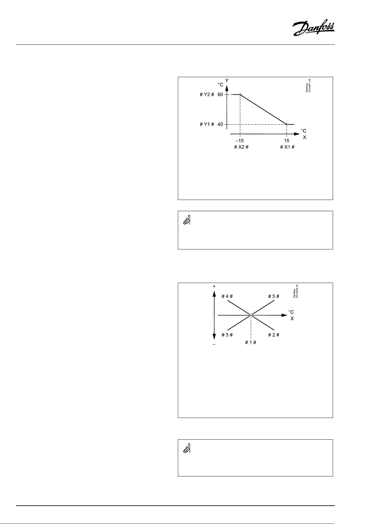
OperatingGuideECLComfort210/310,applicationA267
5.4Returnlimit
Thereturntemperaturelimitationisbasedontheoutdoor
temperature.Typicallyindistrictheatingsystemsahigherreturn
temperatureisacceptedatadecreaseinoutdoortemperature.The
relationshipbetweenthereturntemperaturelimitsandoutdoor
temperatureissetintwocoordinates.
Theoutdoortemperaturecoordinatesaresetin'HighToutX1'
and'LowToutX2' .Thereturntemperaturecoordinatesaresetin
'HighlimitY2'and'LowlimitY1' .
Thecontrollerautomaticallychangesthedesiredflowtemperature
toobtainanacceptablereturntemperaturewhenthereturn
temperaturefallsbeloworgetshigherthanthecalculatedlimit.
ThislimitationisbasedonaPIregulationwhereP('Infl.'factor)
respondsquicklytodeviationsandI('Adapt.time')responds
slowerandovertimeremovesthesmalloffsetsbetweenthe
desiredandactualvalues.Thisisdonebychangingthedesired
flowtemperature.
X
Y
#X1#
#X2#
#Y1#
#Y2#
=
Outdoortemperature
=
Limitationtemperature
=
HighTout(1x031)
=
LowTout(1x033)
=
Lowlimit(1x032)
=
Highlimit(1x034)
DHWcircuit
Thereturntemperaturelimitationisbasedonaconstant
temperaturevalue.
Thecontrollerautomaticallychangesthedesiredflowtemperature
toobtainanacceptablereturntemperaturewhenthereturn
temperaturefallsbeloworgetshigherthanthesetlimit.
ThislimitationisbasedonaPIregulationwhereP('Infl.'factor)
respondsquicklytodeviationsandI('Adapt.time')responds
slowerandovertimeremovesthesmalloffsetsbetweenthe
desiredandactualvalues.Thisisdonebychangingthedesired
flowtemperature.
Thecalculatedlimitisshowninbrackets()inthemonitoringdisplay.
Seethesection"Monitoringtemperaturesandsystemcomponents" .
=
X
#1#
#2#
#3#
#4#
#5#
Returntemperature
=
Limitationtemperature
Negativeinfluence(1x035)whenreturntemp.getshigherthan
=
limit.temp.
Negativeinfluence(1x036)whenreturntemp.getslowerthan
=
limit.temp.
Positiveinfluence(1x036)whenreturntemp.getslowerthanlimit.
=
temp.
Positiveinfluence(1x035)whenreturntemp.getshigherthan
=
limit.temp.
56|©Danfoss|2021.03
Ifthe‘Infl. ’factoristoohighand/orthe‘ Adapt.time’toolow,thereis
ariskofunstablecontrol.
AQ026486454993en-010401
Page 57

OperatingGuideECLComfort210/310,applicationA267
Example,maximumreturntemperaturelimitation;
returntemperaturegetshigherthanlimit
=
T
Y
X
#1#
#2#
#3#
#4#
Temperature
=
Temperature
=
Time
=
Returntemperature
=
Returntemperaturelimit
=
Desiredflowtemperature
=
Actionpoint
AQ026486454993en-010401
©Danfoss|2021.03|57
Page 58

OperatingGuideECLComfort210/310,applicationA267
Example,minimumreturntemperaturelimitation;
returntemperaturegetslowerthanlimit
=
T
Temperature
=
Y
Temperature
=
X
Time
=
#1#
Returntemperature
=
#2#
Returntemperaturelimit
=
#3#
Desiredflowtemperature
=
#4#
Actionpoint
ParametersindicatedwithanIDno.like"1x607"meanauniversal
parameter.
xstandsforcircuit/parametergroup.
MENU>Settings>Returnlimit
Con.T,re.Tlim.(Constanttemperaturemode,return
temperaturelimitation)
The"Con.T ,ret.Tlimit"isthereturntemperaturelimitationvaluewhenthe
circuitissettooverridemodetype"Const.T"(=Constanttemperature).
SeeAppendix“ParameterIDoverview”
Value:Setthereturntemperaturelimitation
1x028
58|©Danfoss|2021.03
AQ026486454993en-010401
Page 59

OperatingGuideECLComfort210/310,applicationA267
MENU>Settings>Returnlimit
Limit(returntemp.limitation)
Setthereturntemperaturevalueyouacceptforthesystem.
1x030
SeeAppendix“ParameterIDoverview”
Whenthereturntemperaturefallsbeloworgetshigherthanthe
setvalue,thecontrollerautomaticallychangesthedesiredflow/
ducttemperaturetoobtainanacceptablereturntemperature.The
influenceissetin'Infl.-max. 'and'Infl.-min.' .
ThereturntemperaturelimitationfortheDHWcircuitisbasedonthe
settingin'Limit(returntemp.limitation)' .
Theinfluencefactorsaresetinheatingcircuit1.
MENU>Settings>Returnlimit
HighToutX1(returntemp.limitation,highlimit,X-axis)
Settheoutdoortemperaturevalueforthelowreturntemperaturelimitation.
SeeAppendix“ParameterIDoverview”
ThecorrespondingYcoordinateissetin'LowlimitY1' .
MENU>Settings>Returnlimit
LowlimitY1(returntemp.limitation,lowlimit,Y-axis)
Setthereturntemperaturelimitationreferringtotheoutdoortemperature
valuesetin'HighToutX1' .
SeeAppendix“ParameterIDoverview”
Ifthereturntemperaturelimitationvalueinheatingcircuit1ishigher
thanthereturntemperaturelimitationvalueintheDHWcircuit,the
highestvalueisused.
1x031
1x032
ThecorrespondingXcoordinateissetin'HighToutX1' .
AQ026486454993en-010401
©Danfoss|2021.03|59
Page 60

OperatingGuideECLComfort210/310,applicationA267
MENU>Settings>Returnlimit
LowToutX2(returntemp.limitation,lowlimit,X-axis)
Settheoutdoortemperaturevalueforthehighreturntemperature
limitation.
SeeAppendix“ParameterIDoverview”
ThecorrespondingYcoordinateissetin'HighlimitY2'.
MENU>Settings>Returnlimit
HighlimitY2(returntemp.limitation,highlimit,Y-axis)
Setthereturntemperaturelimitationreferringtotheoutdoortemperature
valuesetin'LowToutX2' .
SeeAppendix“ParameterIDoverview”
ThecorrespondingXcoordinateissetin'LowToutX2' .
MENU>Settings>Returnlimit
Infl.-max.(returntemp.limitation-max.influence)
Determineshowmuchthedesiredflowtemperaturewillbeinfluencedifthe
returntemperatureishigherthanthesetlimit.
SeeAppendix“ParameterIDoverview”
1x033
1x034
Example
1x035
Thereturnlimitisactiveabove50°C.
Theinfluenceissetto0.5.
Theactualreturntemperatureis2degreestoohigh.
Result:
Thedesiredflowtemperatureischangedby0.5x2=1.0degree.
Influencehigherthan0:
Thedesiredflowtemperatureisincreased,whenthereturn
temperaturegetshigherthanthesetlimit.
Influencelowerthan0:
Thedesiredflowtemperatureisdecreased,whenthereturn
temperaturegetshigherthanthesetlimit.
MENU>Settings>Returnlimit
Infl.-min.(returntemp.limitation-min.influence)
Determineshowmuchthedesiredflowtemperaturewillbeinfluencedifthe
returntemperatureislowerthanthecalculatedlimit.
SeeAppendix“ParameterIDoverview”
Influencehigherthan0:
Thedesiredflowtemperatureisincreased,whenthereturn
temperaturegetsbelowthecalculatedlimit.
Influencelowerthan0:
Thedesiredflowtemperatureisdecreased,whenthereturn
temperaturegetsbelowthecalculatedlimit.
Example
1x036
Thereturnlimitisactivebelow50°C.
Theinfluenceissetto-3.0.
Theactualreturntemperatureis2degreestoolow.
Result:
Thedesiredflowtemperatureischangedby-3.0x2=-6.0degrees.
Normally,thissettingis0indistrictheatingsystemsbecausealower
returntemperatureisacceptable.
Typically,thissettingishigherthan0inboilersystemstoavoidatoo
lowreturntemperature(seealso'Infl.-max.').
60|©Danfoss|2021.03
AQ026486454993en-010401
Page 61

OperatingGuideECLComfort210/310,applicationA267
MENU>Settings>Returnlimit
Adapt.time(adaptationtime)
Controlshowfastthereturntemperatureadaptstothedesiredreturn
temperaturelimit(Integrationcontrol).
SeeAppendix“ParameterIDoverview”
OFF:
Thecontrolfunctionisnotinfluencedbythe‘Adapt.
time’ .
Minor
Thedesiredtemperatureisadaptedquickly.
value:
Major
Thedesiredtemperatureisadaptedslowly.
value:
MENU>Settings>Returnlimit
Priority(priorityforreturntemp.limitation)
Choosewhetherthereturntemperaturelimitationshouldoverruletheset
min.flowtemperature‘Temp.min. ’.
SeeAppendix“ParameterIDoverview”
OFF:
ON:
Themin.flowtemperaturelimitisnotoverruled.
Themin.flowtemperaturelimitisoverruled.
1x037
Theadaptationfunctioncancorrectthedesiredflowtemperature
withmax.8K.
1x085
IfyouhaveaDHWapplication:
Pleasealsosee‘Paralleloperation’(ID11043).
IfyouhaveaDHWapplication:
Whendependentparalleloperationisinfunction:
•Desiredflowtemperaturefortheheatingcircuitwillbeminimum
limited,when"Priorityforreturntemperature"(ID1x085)isset
toOFF.
•Desiredflowtemperaturefortheheatingcircuitwillnotbe
minimumlimited,when"Priorityforreturntemperature"
(ID1x085)issettoON.
AQ026486454993en-010401
©Danfoss|2021.03|61
Page 62

OperatingGuideECLComfort210/310,applicationA267
5.5Optimization
Thesection"Optimization"describesspecificapplicationrelated
issues.
Theparameters'Autosaving' ,'Boost','Optimizer','Totalstop'areall
relatedtoheatingmodeonly.
'Summer,cut-out'determine,atrisingoutdoortemperature,the
stopofheating.
ParametersindicatedwithanIDno.like"1x607"meanauniversal
parameter.
xstandsforcircuit/parametergroup.
62|©Danfoss|2021.03
AQ026486454993en-010401
Page 63

OperatingGuideECLComfort210/310,applicationA267
MENU>Settings>Optimization
Autosaving(savingtemp.dependentonoutdoortemp.)
Belowthesetvaluefortheoutdoortemperature,thesavingtemperature
settinghasnoinfluence.Abovethesetvaluefortheoutdoortemperature,
thesavingtemperaturerelatestotheactualoutdoortemperature.The
functionisrelevantindistrictheatinginstallationsinordertoavoidabig
changeinthedesiredflowtemperatureafterasavingperiod.
SeeAppendix“ParameterIDoverview”
OFF:
Thesavingtemperaturedoesnotdependonthe
outdoortemperature;thereductionis100%.
Value:Thesavingtemperaturedependsontheoutdoor
temperature.Whentheoutdoortemperatureisabove
10°C,thereductionis100%.Thelowertheoutdoor
temperature,thelessthetemperaturereduction.
Belowthesetvalue,thesavingtemperaturesetting
hasnoinfluence.
Comforttemperature:
Thedesiredroomtemperaturein
Comfortmode
Savingtemperature:
ThedesiredroomtemperatureinSaving
mode
ThedesiredroomtemperaturesforComfortandSavingmodes
aresetinthedisplayoverviews.
1x011
=
X
Y
#1#
#2#
#3#
Example:
Actualoutdoortemperature(T.out):
DesiredroomtemperaturesettinginComfortmode:
DesiredroomtemperaturesettinginSavingmode:
Settingin‘Autosaving’:
Outdoortemperature(°C)
=
Desiredroomtemperature(°C)
=
Desiredroomtemperature(°C),Comfortmode
=
Desiredroomtemperature(°C),Savingmode
=
Autosavingtemperature(°C),ID11011
–5°C
22°C
16°C
–15°C
Theconditionfortheoutdoortemperatureinfluence:
T.out.influence=(10-T.out)/(10-setting)=
(10-(-5))/(10-(-15))=
15/25=0,6
ThecorrecteddesiredroomtemperatureinSavingmode:
T.room.ref.Saving+(T.out.influencex(T.room.ref.ComfortT.room.ref.Saving))
16+(0,6x(22-16))=19,6°C
=
X
Y
Outdoortemperature(°C)
=
Desiredroomtemperature(°C)
AQ026486454993en-010401
©Danfoss|2021.03|63
Page 64

OperatingGuideECLComfort210/310,applicationA267
MENU>Settings>Optimization
Boost
Shortenstheheating-upperiodbyincreasingthedesiredflowtemperature
bythepercentageyouset.
SeeAppendix“ParameterIDoverview”
OFF:
Value:
Theboostfunctionisnotactive.
Thedesiredflowtemperatureisincreasedtemporarily
withthesetpercentage.
Inordertoshortentheheating-upperiodafterasaving
temperatureperiod,thedesiredflowtemperaturecanbeincreased
temporarily(max.1hour).Atoptimizingtheboostisactiveinthe
optimizationperiod('Optimizer').
IfaroomtemperaturesensororanECA30/31isconnected,the
booststopswhentheroomtemperatureisreached.
MENU>Settings>Optimization
Ramp(referenceramping)
Thetime(minutes)inwhichthedesiredflowtemperatureincreases
graduallytoavoidloadpeaksintheheatsupply.
SeeAppendix“ParameterIDoverview”
1x012
1x013
OFF:
Value:
Therampingfunctionisnotactive.
Thedesiredflowtemperatureisincreasedgraduallywith
thesetminutes.
Inordertoavoidloadpeaksinthesupplynetwork,theflow
temperaturecanbesettoincreasegraduallyafteraperiodwith
savingtemperature.Thiscausesthevalvetoopengradually.
=
X
Y
#1#
Time
=
Desiredflowtemperature
=
Rampingtime
=
Comforttemperature
=
Savingtemperature
64|©Danfoss|2021.03
AQ026486454993en-010401
Page 65

OperatingGuideECLComfort210/310,applicationA267
MENU>Settings>Optimization
Optimizer(optimizingtimeconstant)
Optimizesthestartandstoptimesforthecomforttemperatureperiodto
obtainthebestcomfortatthelowestenergyconsumption.
Thelowertheoutdoortemperature,theearliertheheatingcut-in.Thelower
theoutdoortemperature,thelatertheheatingcut-out.
Theoptimizedheatingcut-outtimecanbeautomaticordisabled.The
calculatedstartandstoptimesarebasedonthesettingoftheoptimizing
timeconstant.
SeeAppendix“ParameterIDoverview”
Adjusttheoptimizingtimeconstant.
Thevalueconsistsofatwodigitnumber.Thetwodigitshavethe
followingmeaning(digit1=TableI,digit2=TableII).
OFF:
Nooptimization.Theheatingstartsandstopsatthe
timessetintheschedule.
10...59:
SeetablesIandII.
TableI:
1x014
Systemtype
LeftdigitHeataccumulationofthe
building
Radiator
1-light
systems
2-medium
3-heavy
Floorheating
4-medium
systems
5-heavy
TableII:
RightdigitDimensioningtemperatureCapacity
-0-50°Clarge
-1
-45°C
-5
-25°C
normal
MENU>Settings>Optimization
Basedon(optimizationbasedonroom/outdoortemp.)
Theoptimizedstartandstoptimecanbebasedoneitherroomoroutdoor
temperature.
SeeAppendix“ParameterIDoverview”
OUT:
Optimizationbasedonoutdoortemperature.Usethis
settingiftheroomtemperatureisnotmeasured.
ROOM:
Optimizationbasedonroomtemperature,ifmeasured.
-9
Dimensioningtemperature:
Thelowestoutdoortemperature(usuallydeterminedbyyoursystem
designerinconnectionwiththedesignoftheheatingsystem)atwhich
theheatingsystemcanmaintainthedesignedroomtemperature.
Example
Thesystemtypeisradiator,andtheheataccumulationofthebuilding
ismedium.
Theleftdigitis2.
Thedimensioningtemperatureis-25°C,andthecapacityisnormal.
Therightdigitis5.
Result:
Thesettingistobechangedto25.
1x020
-5°C
small
AQ026486454993en-010401
©Danfoss|2021.03|65
Page 66

OperatingGuideECLComfort210/310,applicationA267
MENU>Settings>Optimization
Totalstop
Decidewhetheryouwantatotalstopduringthesavingtemperatureperiod.
1x021
SeeAppendix“ParameterIDoverview”
OFF:
Nototalstop.Thedesiredflowtemperatureisreduced
accordingto:
•desiredroomtemperatureinsavingmode
•autosaving
ON:
Thedesiredflowtemperatureisloweredtothesetvalue
in‘Frostpr. ’Thecirculationpumpisstoppedbutfrost
protectionisstillactive,see'PfrostT' .
Totalstop=OFF
Totalstop=ON
X
Y
=
Time
=
Desiredflowtemperature
=
Comforttemperature
=
Savingtemperature
=
Frostprotection
MENU>Settings>Optimization
Pre-stop(optimizedstoptime)
Disabletheoptimizedstoptime.
SeeAppendix“ParameterIDoverview”
OFF:
ON:
Theoptimizedstoptimeisdisabled.
Theoptimizedstoptimeisenabled.
Themin.flowtemperaturelimitation('Temp.min.')isoverruledwhen
'Totalstop'isON.
1x026
Example:OptimizationofComfortfrom07:00-22:00
=
X
#1#
#2#
#3#
#4#
#5#
Time
=
Schedule
=
Prestop=OFF
=
Prestop=ON
=
Optimizedstart
=
Optimizedstop
66|©Danfoss|2021.03
AQ026486454993en-010401
Page 67

OperatingGuideECLComfort210/310,applicationA267
MENU>Settings>Optimization
Paralleloperation
ChoosewhethertheheatingcircuitistooperateindependenceoftheDHW
circuit.Thisfunctionmightbeusefulifaninstallationhaslimitedpower
orflow.
SeeAppendix“ParameterIDoverview”
OFF:
Independentparalleloperation,i.e.theDHWand
theheatingcircuitsoperateindependentlyofeach
other.ItmakesnodifferencewhetherthedesiredDHW
temperaturecanbereachedornot.
Value:Dependentparalleloperation,i.e.thedesiredheating
temperaturedependsontheDHWdemand.Choose
howmuchtheDHWtemperaturecandropbeforethe
desiredheatingtemperaturehastobedecreased.
1x043
=
X
Y1
Y2
#1#
#2#
#3#
#4#
#5#
#6#
#7#
Time
=
Temperature
=
Temperature
=
Acceptabledeviation(Paralleloperation,1x043)
=
DesiredDHWtemperature
=
ActualDHWtemperature
=
Desiredheatingtemperature
=
Reducedheatingtemperature
=
100%paralleloperation
=
Paralleloperationwithdecreasedheatingtemperature
IftheactualDHWtemperaturedeviatesmorethanthesetvalue,the
gearmotorM2intheheatingcircuitwillgraduallyclosetosuchan
extentthattheDHWtemperaturestabilizesatthelowestacceptable
value.
Ifsettingsinthesettingrange1...99Karechosenfordependent
paralleloperation,theDHWheatingtemperaturestillhashighest
priority.IftheDHWheatingtemperaturecannotbereached,the
circulationpumpfortheheatingcircuitwillbeswitchedOFF.
AQ026486454993en-010401
©Danfoss|2021.03|67
Page 68

OperatingGuideECLComfort210/310,applicationA267
MENU>Settings>Optimization
Summer,cut-out(limitforheatingcut-out)
1x179
SeeAppendix“ParameterIDoverview”
TheheatingcanbeswitchedOFFwhentheoutdoortemperatureis
higherthanthesetvalue.Thevalveclosesandafterthepost-run
time,theheatingcirculationpumpstops.‘Temp.min.’willbe
overruled.
TheheatingsystemswitchesONagainwhentheoutdoor
temperatureandtheaccumulated(filtered)outdoortemperature
becomelowerthanthesetlimit.
Thisfunctioncansaveenergy.
Setthevalueforoutdoortemperatureatwhichyouwantthe
heatingsystemtoswitchOFF .
Summer,cut-out
=
X
Y
#1#
#2#
#3#
#4#
#5#
Time
=
Temperature
=
Actualoutdoortemperature
=
Cut-outtemperature(1x179)
=
Accummulated(filtered)outdoortemperature
=
Heatingenabled
=
Heatingdisabled
Theheatingcut-outisonlyactivewhenthecontrollermodeisin
scheduledoperation.Whenthecut-outvalueissettoOFF,thereis
noheatingcut-out.
68|©Danfoss|2021.03
AQ026486454993en-010401
Page 69

OperatingGuideECLComfort210/310,applicationA267
5.6Controlparameters
Controlofvalves
Themotorizedcontrolvalvesarecontrolledbymeansof3-point
controlsignal.
Valvecontrol:
Themotorizedcontrolvalveisopenedgraduallywhentheflow
temperatureislowerthanthedesiredflowtemperatureandvice
versa.
Thewaterflowthroughthecontrolvalveismanagedbymeans
ofanelectricactuator.Thecombination"actuator"and"control
valve"isalsocalledmotorizedcontrolvalve.Theactuatorcanin
thiswaygraduallyincreaseordecreasetheflowinordertochange
thesuppliedenergy.Differenttypesofactuatorsareavailable.
3-pointcontrolledactuator:
Theelectricactuatorcontainsareversiblegear-motor.Electric
"open"and"close"signalscomefromtheelectronicoutputsofthe
ECLComfortcontrollerinordertomanagethecontrolvalve.The
signalsareintheECLComfortcontrollerexpressedas"Arrow-up"
(open)and"Arrow-down"(close)anddisplayedatthevalvesymbol.
Whentheflowtemperature(forexampleatS3)islowerthanthe
desiredflowtemperature,shortopen-signalscomefromtheECL
Comfortcontrollerinordertograduallyincreasetheflow.Bythis,
theflowtemperaturewillalignwiththedesiredtemperature.
Oppositely,whentheflowtemperatureishigherthanthedesired
flowtemperature,shortclose-signalscomefromtheECLComfort
controllerinordertograduallyreducetheflow.Again,theflow
temperaturealignswiththedesiredtemperature.
Neitheropen-signalsnorclose-signalswillcomeaslongastheflow
temperaturecorrespondstothedesiredtemperature.
AQ026486454993en-010401
©Danfoss|2021.03|69
Page 70

OperatingGuideECLComfort210/310,applicationA267
Thermo-hydraulicactuator,ABV
Danfossthermo-actuatortypeABVisaslowactingvalveactuator.
InsidetheABVanelectricheatcoilwillheatathermostaticelement
whenanelectricsignalisapplied.Whenheatingthethermostatic
elementitexpandsinordertomanagethecontrolvalve.
Twobasictypesareavailable:ABVNC(NormalClosed)andABVNO
(normalopen).Forexample,ABVNCkeepsa2-portcontrolvalve
closedwhennoopen-signalsareapplied.
Electricopen-signalscomefromtheelectronicoutputoftheECL
Comfortcontrollerinordertomanagethecontrolvalve.When
open-signalsareappliedtotheABVNC,thevalvegraduallyopens.
Open-signalsareintheECLComfortcontrollerexpressedas
"Arrow-up"(open)anddisplayedatthevalvesymbol.
Whentheflowtemperature(forexampleatS3)islowerthanthe
desiredflowtemperature,relativelylongopen-signalscomefrom
theECLComfortcontrollerinordertoincreasetheflow.Bythis,
theflowtemperaturewillovertimebealignedwiththedesired
temperature.
Oppositely,whentheflowtemperatureishigherthanthedesired
flowtemperature,relativelyshortopen-signalscomefromtheECL
Comfortcontrollerinordertoreducetheflow.Again,theflow
temperaturealigns,overtime,withthedesiredtemperature.
ThecontroloftheDanfossthermo-actuatortypeABVusesaunique
designedalgorithmandisbasedonthePWMprinciple(Pulse
WidthModulation),wherethedurationofthepulsedetermines
themanagementofthecontrolvalve.Thepulsesarerepeated
each10sec.
Aslongastheflowtemperaturecorrespondstothedesired
temperature,thedurationoftheopen-signalswillremainconstant.
ParametersindicatedwithanIDno.like"1x607"meanauniversal
parameter.
xstandsforcircuit/parametergroup.
MENU>Settings>Controlparameters
Actuator
ABV/GEAR
1x024
GEAR
Selectionofvalveactuatortype.
Whenselecting"ABV",thecontrolparameters:
•Motorprotection(ID1x174)
ABV:
GEAR:
70|©Danfoss|2021.03
DanfosstypeABV(thermoactuator).
Gearmotorbasedactuator.
•Xp(ID1x184)
•Tn(ID1x185)
•Mrun(ID1x186)
•Nz(ID1x187)
•Min.act.time(ID1x189)
arenotconsidered.
AQ026486454993en-010401
Page 71

OperatingGuideECLComfort210/310,applicationA267
MENU>Settings>Controlparameters
Motorpr.(motorprotection)
Preventsthecontrollerfromunstabletemperaturecontrol(andresulting
actuatoroscillations).Thiscanoccuratverylowload.Themotorprotection
increasesthelifetimeofallinvolvedcomponents.
SeeAppendix“ParameterIDoverview”
OFF:
Value:
Motorprotectionisnotactivated.
Motorprotectionisactivatedafterthesetactivation
delayinminutes.
MENU>Settings>Controlparameters
Xp(proportionalband)
SeeAppendix“ParameterIDoverview”
Settheproportionalband.Ahighervaluewillresultinastablebut
slowcontroloftheflowtemperature.
MENU>Settings>Controlparameters
Tn(integrationtimeconstant)
1x174
Recommendedforductsystemswithvariableload.
1x184
1x185
SeeAppendix“ParameterIDoverview”
Setahighintegrationtimeconstant(inseconds)toobtainaslow
butstablereactiontodeviations.
Alowintegrationtimeconstantwillmakethecontrollerreactfast
butwithlessstability.
MENU>Settings>Controlparameters
Mrun(runningtimeofthemotorizedcontrolvalve)
‘Mrun’isthetimeinsecondsittakesthecontrolledcomponenttomove
fromfullyclosedtofullyopenposition.
SeeAppendix“ParameterIDoverview”
Setthe‘Mrun’accordingtotheexamplesormeasuretherunning
timebymeansofastopwatch.
1x186
Howtocalculatetherunningtimeofamotorizedcontrolvalve
Therunningtimeofthemotorizedcontrolvalveiscalculatedusing
thefollowingmethods:
Seatedvalves
Runningtime=
Example:
Rotatingvalves
Runningtime=
Example:90degr.x2sec./degr.=180sec.
Valvestroke(mm)xactuatorspeed(sec./mm)
5.0mmx15sec./mm=75sec.
Turningdegreesxactuatorspeed(sec./degr.)
AQ026486454993en-010401
©Danfoss|2021.03|71
Page 72

OperatingGuideECLComfort210/310,applicationA267
MENU>Settings>Controlparameters
Nz(neutralzone)
Whentheactualflowtemperatureiswithintheneutralzone,thecontroller
doesnotactivatethemotorizedcontrolvalve.
SeeAppendix“ParameterIDoverview”
Settheacceptableflowtemperaturedeviation.
Settheneutralzonetoahighvalueifyoucanacceptahigh
variationinflowtemperature.
MENU>Settings>Controlparameters
Min.act.time(min.activationtimegearmotor)
Themin.pulseperiodof20ms(milliseconds)foractivationofthegear
motor.
SeeAppendix“ParameterIDoverview”
1x187
Theneutralzoneissymmetricalaroundthedesiredflowtemperature
value,i.e.halfthevalueisaboveandhalfthevalueisbelowthis
temperature.
SettingexampleValuex20ms
1x189
240ms
10200ms
501000ms
Thesettingshouldbekeptashighasacceptabletoincreasethe
lifetimeoftheactuator(gearmotor).
IfyouwanttotunethePIregulationprecisely,youcanusethefollowingmethod:
•Setthe‘Tn’(integrationtimeconstant)toitsmax.value(999sec.).
•Decreasethevalueforthe‘Xp’(proportionalband)untilthesystemstartshunting(i.e.getsunstable)withaconstantamplitude(it
mightbenecessarytoforcethesystembysettinganextremelowvalue).
•Findthecriticaltimeperiodonthetemperaturerecorderoruseastopwatch.
Temp.
Criticaltimeperiod
Time
Thiscriticaltimeperiodwillbecharacteristicforthesystem,andyoucanevaluatethesettingsfromthiscriticalperiod.
‘Tn’=
0.85xcriticaltimeperiod
‘Xp’=
2.2xproportionalbandvalueinthecriticaltimeperiod
Iftheregulationseemstobetooslow,youcandecreasetheproportionalbandvalueby10%.Makesurethereisaconsumption
whenyousettheparameters.
72|©Danfoss|2021.03
AQ026486454993en-010401
Page 73

OperatingGuideECLComfort210/310,applicationA267
5.7Application
Thesection"Application"describesspecificapplicationrelated
issues.
Someoftheparameterdescriptionsareuniversalfordifferent
applicationkeys.
ParametersindicatedwithanIDno.like"1x607"meanauniversal
parameter.
xstandsforcircuit/parametergroup.
MENU>Settings>Application
ECAaddr.(ECAaddress,choiceofRemoteControlUnit)
Decidestheroomtemperaturesignaltransferandcommunicationwiththe
RemoteControlUnit.
SeeAppendix“ParameterIDoverview”
OFF:
NoRemoteControlUnit.Onlyroomtemperaturesensor,
ifany.
A:
B:
RemoteControlUnitECA30/31withaddressA.
RemoteControlUnitECA30/31withaddressB.
MENU>Settings>Application
Demandoffset
Thedesiredflowtemperatureinheatingcircuit1canbeinfluencedbythe
demandforadesiredflowtemperaturefromanothercontroller(slave)or
anothercircuit.
SeeAppendix“ParameterIDoverview”
OFF:
Thedesiredflowtemperatureincircuit1isnot
influencedbythedemandofanyothercontroller(slave
orcircuit2).
Value:
Thedesiredflowtemperatureisincreasedbytheset
valuein‘Demandoffset’ ,ifthedemandoftheslave/
circuit2ishigher.
1x010
TheRemoteControlUnitmustbesetaccordingly(AorB).
Temp.
1x017
Settingin
‘Demandoffset’
Des.flowtemp.,
circuit1
Des.flowtemp.,
circuit2
Time
Thefunctionof‘Demandoffset’cancompensateforheatlosses
betweenmasterandslavecontrolledsystems.
Whensetting"Demandoffset"toavalue,thereturntemperature
limitationwillreactaccordingtothehighestlimitationvalue(Heating
/DHW).
AQ026486454993en-010401
©Danfoss|2021.03|73
Page 74

OperatingGuideECLComfort210/310,applicationA267
MENU>Settings>Application
Pexercise(pumpexercise)
Exercisesthepumptoavoidblockinginperiodswithoutheatdemand.
SeeAppendix“ParameterIDoverview”
OFF:
ON:
Thepumpexerciseisnotactive.
ThepumpisswitchedONfor1minuteeverythirddayat
noon(12:14hours).
MENU>Settings>Application
Mexercise(valveexercise)
Exercisesthevalvetoavoidblockinginperiodswithoutheatdemand.
SeeAppendix“ParameterIDoverview”
OFF:
ON:
Thevalveexerciseisnotactive.
Thevalveopensfor7minutesandclosesfor7minutes
everythirddayatnoon(12:00hours).
MENU>Settings>Application
1x022
1x023
Ppost-run
Heatingapplications:
ThecirculationpumpintheheatingcircuitcanbeONforanumberof
minutes(m)afterheatingstop.Heatingstopiswhenthedesiredflow
temperaturegetslowerthanthesettingin'PheatT'(IDno.1x078).
Coolingapplications:
ThecirculationpumpinthecoolingcircuitcanbeONforanumberof
minutes(m)aftercoolingstop.Coolingstopiswhenthedesiredflow
temperaturegetshigherthanthesettingin'PcoolT'(IDno.1x070).
ThisPpost-runfunctioncanutilizetheremainingenergyinforexamplea
heatexchanger.
SeeAppendix“ParameterIDoverview”
0:
Thecirculationpumpstopsimmediatelyafterheating
orcoolingstop.
Value:
ThecirculationpumpisONforthesettimeafterheating
orcoolingstop.
MENU>Settings>Application
DHWPpost-run(DHWpump,post-run)
SettheDHWpumppost-runtime(minutes).TheDHWpumpcancontinue
tobeswitchedONaftertheDHWheatingprocedureinordertoutilizethe
remainingheatintheheatexchanger/boiler.
1x040
1x041
SeeAppendix“ParameterIDoverview”
Value:
Setthenumberofminutesforthepost-run.
74|©Danfoss|2021.03
AQ026486454993en-010401
Page 75

OperatingGuideECLComfort210/310,applicationA267
MENU>Settings>Application
Max.DHWtime
SetthemaxDHWheatingtime(minutes).WhenDHWheatingisactiveand
theset'Max.DHWtime'expires,DHWheatingisdeactivated.
1x044
SeeAppendix“ParameterIDoverview”
OFF:
IftheDHWtemperatureislowerthantheDHWcharging
cut-intemperature,theDHWchargingremainsactive
forunlimitedperiodoftime.IftheDHWtemperatureis
higherthantheDHWchargingcut-intemperature,the
chargingisdeactivatedafter35minutes.
Value:TheDHWheating/chargingisdeactivatedwhentheset
'Max.DHWtime'(inminutes)expires.
MENU>Settings>Application
DHWdeact.time(DHWdeactivationtime)
Setthetime(minutes)thatmustelapseafteraDHWheatingperiodbeforea
newDHWheatingperiodcanbestarted.
1x045
SeeAppendix“ParameterIDoverview”
Value:WhentheDHWheating/chargingtimehasreachedits
maximum,DHWcanonlybeheated/chargedagain
afterthesetdeactivationtime(inminutes)hasexpired.
MENU>Settings>Application
Pdemand
Thecirculationpumpinthemastercircuitcanbecontrolledinrelationto
themastercircuit'sdemandorslavecircuit'sdemand.
SeeAppendix“ParameterIDoverview”
Heatingapplications:
OFF:
ThecirculationpumpisONwhenthedesiredflow
temperatureintheheatingcircuitishigherthanthe
valuesetin'PheatT'.
ON:
ThecirculationpumpisONwhenthedesiredflow
temperaturefromslavesishigherthanthevaluesetin
'PheatT'.
Coolingapplications:
OFF:
ThecirculationpumpisONwhenthedesiredflow
temperatureinthecoolingcircuitislowerthanthevalue
setin'PcoolT'.
ON:
ThecirculationpumpisONwhenthedesiredflow
temperaturefromslavesislowerthanthevaluesetin
'PcoolT'.
1x050
Thecirculationpumpisalwayscontrolledaccordingtofrostprotection
conditions.
AQ026486454993en-010401
©Danfoss|2021.03|75
Page 76

OperatingGuideECLComfort210/310,applicationA267
MENU>Settings>Application
Ch.-o.valve/P(changeovervalve/pump)
ChoosewhethertheDHWheatingcontrolisbasedonachangeovervalve
orapump.
SeeAppendix“ParameterIDoverview”
OFF:
ON:
Changeovervalve
Pump
MENU>Settings>Application
DHWpriority(closedvalve/normaloperation)
Theheatingcircuitcanbeclosedwhenthecontrolleractsasslaveandwhen
DHWheating/chargingisactiveinthemaster.
SeeAppendix“ParameterIDoverview”
OFF:
Theflowtemperaturecontrolremainsunchanged
duringactiveDHWheating/charginginthemaster
controller.
ON:
Thevalveintheheatingcircuitisclosed*duringactive
DHWheating/charginginthemastercontroller.
*Thedesiredflowtemperatureissettothevaluesetin
‘Frostpr.T’
1x051
Whenthechangeovervalveischosen,pumpP1isONatheatingas
wellasatDHWheatingdemand.
Whenthepumpischosen,pumpP1isONatheatingandOFFatDHW
heatingdemand.
Aparalleloption(heatingandDHWheatinginparallel)exists,based
onthesetting‘Paralleloperation’ .
1x052
Thissettingmustbeconsideredifthiscontrollerisaslave.
MENU>Settings>Application
Tank,sec./prim.(Tanksecondarilyorprimarily
connected)
ChoosewhethertheheatingoftheDHWtankisdependentontheflow
temperatureatS3.
SeeAppendix“ParameterIDoverview”
OFF:
TheDHWtankisplacedonthesecondarysideofthe
heatexchangerandtheS3temperaturedetermines
theDHWheating.
ON:
TheDHWtankisplacedontheprimarysideoftheheat
exchangerandtheS3temperaturehasnoinfluence
ontheDHWheating.
1x053
76|©Danfoss|2021.03
AQ026486454993en-010401
Page 77

OperatingGuideECLComfort210/310,applicationA267
MENU>Settings>Application
Circ.Ppriority
ChoosewhethertheDHWcirculationpumpshouldbeONduringDHW
heating.
SeeAppendix“ParameterIDoverview”
OFF:
TheDHWcirculationpumpisswitchedOFFduringDHW
heating.
ON:
TheDHWcirculationpumpisnotswitchedOFFduring
DHWheating.
MENU>Settings>Application
Pchargedelay(Chargingpump,delayedstart)
ConditionsforswitchingtheDHWheating/chargingpumpONatDHW
heating/chargingdemand.
Correctsettingcanavoiddischarging.
SeeAppendix“ParameterIDoverview”
OFF:
DHWheating/chargingpumpisswitchedONwhen
DHWheating/chargingtemperatureisOK.
0:
Value:
DHWheating/chargingpumpisswitchedON.
DHWheating/chargingpumpisswitchedONafterthe
setnumberofminutes.
1x055
Whenthe'Circ.Ppriority'issettoOFF ,theschedulefortheDHW
circulationpumpisoverruled.
1x059
Whenthesetting"OFF"isselected,thetemperaturesensorforDHW
heating/chargingmustbeplacedintheheat-exchanger.
MENU>Settings>Application
Circ.PfrostT
SettheoutdoortemperaturevalueatwhichtheDHWcirculationpumpisto
beactivetoprotecttheDHWcircuitagainstfrost.
SeeAppendix“ParameterIDoverview”
OFF:
Value:
TheDHWcirculationpumpisnotactive.
TheDHWcirculationpumpisactivewhentheoutdoor
temperatureislowerthanthesetvalue.
MENU>Settings>Application
PfrostT(circulationpump,frostprotectiontemp.)
Frostprotection,basedontheoutdoortemperature.
Whentheoutdoortemperaturegetsbelowthesettemperaturevaluein‘P
frostT’ ,thecontrollerautomaticallyswitchesONthecirculationpump(for
exampleP1orX3)toprotectthesystem.
SeeAppendix“ParameterIDoverview”
OFF:
Value:
Nofrostprotection.
CirculationpumpisONwhentheoutdoortemperature
isbelowthesetvalue.
1x076
1x077
Undernormalconditions,yoursystemisnotfrostprotectedifyour
settingisbelow0°CorOFF.
Forwater-basedsystems,asettingof2°Cisrecommended.
Iftheoutdoortemperaturesensorisnotconnectedandthefactory
settinghasnotbeenchangedto'OFF' ,thecirculationpumpisalways
ON.
AQ026486454993en-010401
©Danfoss|2021.03|77
Page 78

OperatingGuideECLComfort210/310,applicationA267
MENU>Settings>Application
PheatT(heatdemand)
Whenthedesiredflowtemperatureisabovethesettemperaturein‘PheatT’ ,
thecontrollerautomaticallyswitchesONthecirculationpump.
1x078
SeeAppendix“ParameterIDoverview”
Value:ThecirculationpumpisswitchedONwhenthedesired
flowtemperatureisabovethesetvalue.
MENU>Settings>Application
Frostpr .T(frostprotectiontemp.)
SetthedesiredflowtemperatureattemperaturesensorS3toprotectthe
systemagainstfrost(atheatingcut-out,totalstopetc.).
WhenthetemperatureatS3getslowerthanthesetting,themotorized
controlvalveopensgradually.
1x093
SeeAppendix“ParameterIDoverview”
Thevalveisfullyclosedaslongasthepumpisnotswitchedon.
Thefrostprotectiontemperaturecanalsobesetinyourfavorite
displaywhenthemodeselectorisinfrostprotectionmode.
78|©Danfoss|2021.03
AQ026486454993en-010401
Page 79

OperatingGuideECLComfort210/310,applicationA267
Overridemodefunctions:
ThefollowingsettingsdescribethefunctioningeneralfortheECL
Comfort210/296/310series.Theexplainedmodesaretypical
andnotapplicationrelated.Theymightdifferfromtheoverride
modesinyourapplication.
MENU>Settings>Application
Ext.input(externaloverride)
Choosetheinputfor'Ext.input'(externaloverride).Bymeansofaswitch
thecontrollercanbeoverriddento‘Comfort’,'Saving' ,'Frostprotection'or
'Constanttemperature'mode.
1x141
SeeAppendix“ParameterIDoverview”
OFF:
S1...S16:
Noinputshavebeenselectedforexternaloverride.
Inputselectedforexternaloverride.
IfS1...S6ischosenasoverrideinput,theoverrideswitchmusthave
gold-platedcontacts.
IfS7...S16ischosenasoverrideinput,theoverrideswitchcanbea
standardcontact.
Seethedrawingsforconnectionexamplesofoverrideswitchand
overriderelaytoinputS8.
S7...S16arerecommendedforoverrideswitch.
Example:Connectionofanoverrideswitch
Example:Connectionofanoverriderelay
IfECA32ismounted,alsoS11...S16canbeused.
IfECA35ismounted,alsoS11orS12canbeused.
Chooseonlyanunusedinputforoverride.Ifanalreadyusedinputis
appliedforoverride,thefunctionalityofthisinputisalsoneglected.
Seealso‘Ext.mode’.
AQ026486454993en-010401
©Danfoss|2021.03|79
Page 80

OperatingGuideECLComfort210/310,applicationA267
MENU>Settings>Application
Ext.mode(externaloverridemode)
ThemodeoverridecanbeactivatedforSaving,Comfort,Frostpr.or
ConstantTmode.
Foroverride,thecontrollermodemustbeinscheduledmode.
SeeAppendix“ParameterIDoverview”
Chooseanoverridemode:
SAVING:
Thecircuitinquestionisinsavingmodewhenthe
overrideswitchisclosed.
COMFORT:
Thecircuitinquestionisincomfortmodewhenthe
overrideswitchisclosed.
FROSTPR.:
TheheatingorDHWcircuitcloses,butisstillfrost
protected.
CONSTANTT:
Thecircuitinquestioncontrolsaconstant
temperature*)
*)
Seealso'DesiredT'(1x004),settingofdesiredflow
temperature(MENU>Settings>Flowtemperature)
Seealso'Con.T,ret.Tlim. '(1x028),settingofreturn
temperaturelimitation(MENU>Settings>Return
limit)
Theprocessdiagramsshowthefunctionality.
1x142
Seealso‘Ext.input’.
Example:OverridetoComfortmode
#1#=Overrideswitch(notactivated/activated)
#2#=Functionmode(Schedule/Comfort)
#3#=Time
Example:OverridetoSavingmode
#1#=Overrideswitch(notactivated/activated)
#2#=Functionmode(Schedule/Saving)
#3#=Time
Theresultofoverrideto'Saving'modedependsonthesettingin
'Totalstop'.
Totalstop=OFF:Heatingreduced
Totalstop=ON:Heatingstopped
80|©Danfoss|2021.03
AQ026486454993en-010401
Page 81

OperatingGuideECLComfort210/310,applicationA267
Example:OverridetoFrostprotectionmode
#1#=Overrideswitch(notactivated/activated)
#2#=Functionmode(Schedule/Frostpr.)
#3#=Time
Example:OverridetoConstanttemperaturemode
#1#=Overrideswitch(notactivated/activated)
#2#=Functionmode(Schedule/Const.T)
#3#=Time
The"Const.T"valuecanbeinfluencedby:
•temp.max.
•temp.min.
•roomtemp.limit
•returntemp.limit
•flow/powerlimit
AQ026486454993en-010401
©Danfoss|2021.03|81
Page 82

OperatingGuideECLComfort210/310,applicationA267
MENU>Settings>Application
SenddesiredT
Whenthecontrolleractsasaslavecontrollerinamaster/slavesystem,
informationaboutthedesiredflowtemperaturecanbesenttothemaster
controllerviatheECL485bus.
Stand-alonecontroller:
Sub-circuitscansendthedesiredflowtemperaturetothemastercircuit.
SeeAppendix“ParameterIDoverview”
OFF:
Informationaboutthedesiredflowtemperatureisnot
senttothemastercontroller.
ON:
Informationaboutthedesiredflowtemperatureissent
tothemastercontroller.
1x500
Inthemastercontroller,'Demandoffset'mustbesettoavalueinorder
toreactonadesiredflowtemperaturefromaslavecontroller.
Whenthecontrolleractsasaslave,itsaddressmustbe1,2,3...9in
ordertosendthedesiredtemperaturetothemaster(seethesection
‘Miscellaneous’ ,‘Severalcontrollersinthesamesystem’).
82|©Danfoss|2021.03
AQ026486454993en-010401
Page 83

OperatingGuideECLComfort210/310,applicationA267
5.8Heatcut-out
MENU>Settings>Heatcut-out
Thesetting“Summercut-out”under“Optimization”fortheheating
circuitinquestiondeterminesaheatingcut-outwhentheoutdoor
temperatureexceedsthesetvalue.
Afilteringconstantforcalculatingtheaccumulatedoutdoor
temperatureisinternallysettoavalueof"250".Thisfiltering
constantrepresentsanaveragebuildingwithsolidouterandinner
walls(bricks).
Anoptionfordifferentiatedcut-outtemperatures,basedona
setsummerperiod,canbeutilizedinordertoavoiddiscomfort
atfallingoutdoortemperature.Furthermore,separatefiltering
constantscanbeset.
ThefactorysetvaluesforSummerperiodstartandWinterperiod
startaresettosamedate:May,20(Date=20,Month=5).
Thismeans:
•"Differentiatedcut-outtemperatures"aredisabled(notactive)
•Separate"Filteringconstant"valuesaredisabled(notactive)
Inordertoenabledifferentiated
•cut-outtemperaturebasedonsummer/winterperiod
•filteringconstants
thestartdatesfortheperiodsmustbedifferent.
AQ026486454993en-010401
©Danfoss|2021.03|83
Page 84

OperatingGuideECLComfort210/310,applicationA267
5.8.1Differentiatedheatcut-out
Tosetdifferentiatedcut-outparametersforaheatingcircuitfor
“Summer”and“Winter”goto“Heatcut-out”:
(MENU>Settings>Heatcut-out)
Thisfunctionisactivewhenthedatesfor“Summer”and“Winter”
aredifferentinthe“Heatcut-out”menu.
ParametersindicatedwithanIDno.like"1x607"meanauniversal
parameter.
xstandsforcircuit/parametergroup.
MENU>Settings>Heatcut-out
Extendedheatcut-outsetting
ParameterIDSettingrange
Summerday
Summermonth
Summercut-out
Summerfilter
1x393
1x392
1x179
1x395
**
**
**
**
Factory
setting
SeeAppendix“ParameterIDoverview”
MENU>Settings>Heatcut-out
Extendedwintercut-outsetting
ParameterIDSettingrange
Winterday
Wintermonth
Wintercut-out
Winterfilter
1x397
1x396
1x398
1x399
**
**
**
**
Factory
SeeAppendix“ParameterIDoverview”
Theabovesettingsofthedatesforthecut-outfunctionareonly
tobedoneintheheatingcircuit1andarevalidforotherheating
circuitsinthecontrolleraswell,ifapplicable.
Thecut-outtemperaturesaswellasthefilterconstantaretobeset
individuallyperheatingcircuit.
setting
Theheatingcut-outisonlyactivewhenthecontrollermodeisin
scheduledoperation.Whenthecut-outvalueissettoOFF,thereis
noheatingcut-out.
84|©Danfoss|2021.03
AQ026486454993en-010401
Page 85

OperatingGuideECLComfort210/310,applicationA267
5.8.2Summer/winterfilterconstant
Thefilterconstantof250isapplicableforaveragebuildings.A
filterconstantof1iscloseswitchingaccordingtoactualoutdoor
temperaturemeaninglowfiltering(very“light”building).
Afilterconstantof300isthentobechosenifabigfilteringis
needed(veryheavybuilding).
Forheatingcircuitswheretheheatcut-outisdemandedaccording
tothesameoutdoortemperatureforthewholeyear,butdifferent
filteringiswanted,differentdateshavetobesetinthe“Heat
cut-out”menuenablingaselectionofafilterconstantdifferent
fromthefactorysetting.
Thesedifferentvalueshavetobesetinboththe“Summer”and
“Winter”menu.
AQ026486454993en-010401
©Danfoss|2021.03|85
Page 86
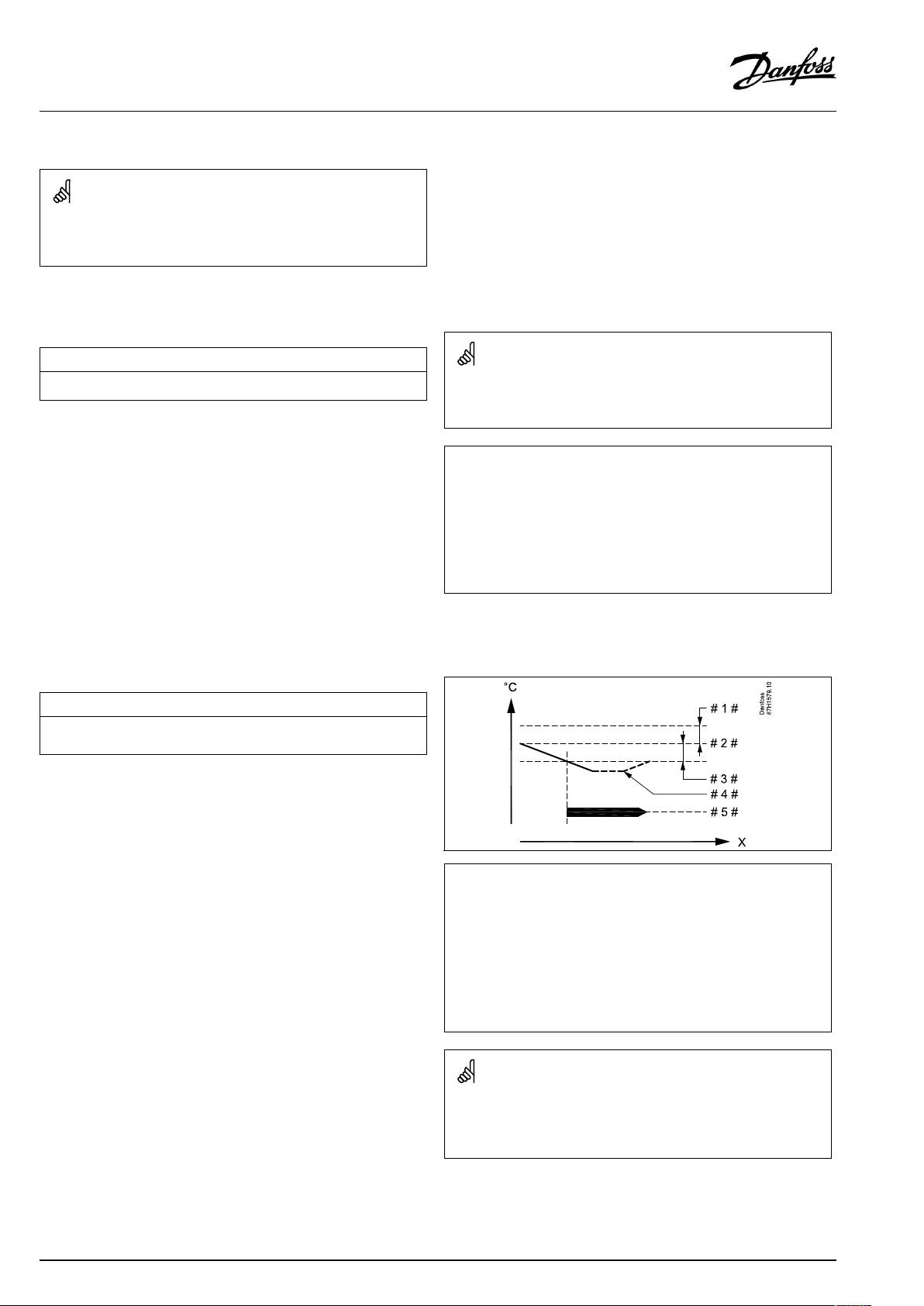
OperatingGuideECLComfort210/310,applicationA267
5.9Tanktemperature
ParametersindicatedwithanIDno.like"1x607"meanauniversal
parameter.
xstandsforcircuit/parametergroup.
MENU>Settings>Tanktemperature
Max.chargeT(maximumheating/chargingtemperature)
Setthemax.heating/chargingtemperaturefortheDHW.
SeeAppendix“ParameterIDoverview”
Value:Setthetemperature.
MENU>Settings>Tanktemperature
Chargedifference
SetthenumberofdegreesabovethedesiredDHWtemperaturethatwill
resultintheDHWheating(charging)temperature.
SeeAppendix“ParameterIDoverview”
1x152
NOTE:
ThedesiredDHWtemperaturewillbereducedif"Max.chargeT"is
lowerthan(DesiredDHWtemp.+Chargedifference).
Example:
DesiredDHWtemp.=
Chargedifference=
Max.chargeT=
Result:
DesiredDHWtemp.willbereducedto45°C.
1x193
50°C
10K
55°C
Value:
NumberofdegreestobeaddedtothedesiredDHW
temperaturetoobtaintheDHWheating(charging)
temperature.
=
X
#1#
#2#
#3#
#4#
#5#
ThedesiredDHWtemperatureisrelatedtothetanktemperature
sensor.
Iftwotanktemperaturesensorsareinstalled,therelationistothe
uppertanktemperaturesensor.
Time
=
Chargingdifference(ID1x193)
=
DesiredDHWtemperature
=
Startdifference(ID1x195)
=
ActualDHWtemperature
=
DHWheating/chargingactivity
86|©Danfoss|2021.03
AQ026486454993en-010401
Page 87

OperatingGuideECLComfort210/310,applicationA267
MENU>Settings>Tanktemperature
Stopdifference
OneDHWtanktemperaturesensor:
SetthenumberofdegreesabovethedesiredDHWtemperaturethatwill
stoptheDHWheating(charging).
TwoDHWtanktemperaturesensors:
SetthenumberofdegreesaboveorbelowthedesiredDHWtemperature,
butmeasuredbythelowertanktemperaturesensorthatwillstoptheDHW
heating(charging).
SeeAppendix“ParameterIDoverview”
–50...50:
Setthenumberofdegrees.
OneDHWtanktemperaturesensor(examplewithpositive‘Stop
difference’value):
1x194
Temp.
Stopdifference
DesiredDHWtemp.
Time
DHWheating
OneDHWtanktemperaturesensor(examplewithnegative‘Stop
difference’value):
Temp.
Stopdifference
DesiredDHWtemp.
Time
DHWheating
TwoDHWtanktemperaturesensors,upperandlower
Temp.
UpperDHWtemp.sensor
Stopdifference
DesiredDHWtemp.
LowerDHWtemp.sensor
Time
DHWheating
AQ026486454993en-010401
©Danfoss|2021.03|87
Page 88

OperatingGuideECLComfort210/310,applicationA267
MENU>Settings>Tanktemperature
Startdifference
SetthenumberofdegreesbelowthedesiredDHWtemperaturethatwill
starttheDHWheating(charging).
SeeAppendix“ParameterIDoverview”
Value:
Setthenumberofdegrees.
1x195
=
X
#1#
#2#
#3#
#4#
#5#
Example:
DesiredDHWtemp.:
Startdifference:
Result:
TheDHWheatingstartswhenthetemperaturemeasuredbythetank
temperaturesensor(upper)islowerthan52°C.
Time
=
Chargingdifference(ID1x193)
=
DesiredDHWtemperature
=
Startdifference(ID1x195)
=
ActualDHWtemperature
=
DHWheating/chargingactivity
55°C
-3K
88|©Danfoss|2021.03
AQ026486454993en-010401
Page 89

OperatingGuideECLComfort210/310,applicationA267
5.10Anti-bacteria
OnselecteddaysduringtheweektheDHWtemperaturecan
beincreasedinordertoneutralizebacteriaintheDHWsystem.
ThedesiredDHWtemperature'DesiredT'(typically80°C)willbe
presentfortheselectedday(s)andduration.
Theanti-bacteriafunctionisnotactiveinfrostprotectionmode.
=
X
Y
#1#
#2#
#3#
#4#
#5#
Time
=
DesiredDHWtemperature
=
Duration
=
DesiredAnti-bacteriatemperaturevalue
=
DesiredAnti-bacteriatemperature
=
DesiredDHWtemperaturevalue
=
Starttime
MENU>Settings>Anti-bacteria
Day
Select(mark)theday(s)oftheweekwheretheanti-bacteriafunctionmust
beactive.
=
Monday
M
=
Tuesday
T
=
Wednesday
W
=
Thursday
T
=
Friday
F
=
Saturday
S
=
Sunday
S
Duringtheanti-bacteriaprocess,thereturntemperaturelimitationis
notactive.
AQ026486454993en-010401
©Danfoss|2021.03|89
Page 90

OperatingGuideECLComfort210/310,applicationA267
MENU>Settings>Anti-bacteria
Starttime
Setthestarttimefortheanti-bacteriafunction.
MENU>Settings>Anti-bacteria
Duration
Settheduration(minutes)fortheanti-bacteriafunction.
MENU>Settings>Anti-bacteria
DesiredT
SetthedesiredDHWtemperaturefortheanti-bacteriafunction.
SeeAppendix“ParameterIDoverview”
OFF:
Value:
Theanti-bacteriafunctionisnotactive.
DesiredDHWtemperatureduringtheanti-bacteria
functionperiod.
90|©Danfoss|2021.03
AQ026486454993en-010401
Page 91

OperatingGuideECLComfort210/310,applicationA267
6.0Commoncontrollersettings
6.1Introductionto‘Commoncontrollersettings’
Somegeneralsettingswhichapplytotheentirecontrollerare
locatedinaspecificpartofthecontroller.
Toenter‘Commoncontrollersettings’:
Action:Purpose:
Choose‘MENU’inanycircuit
Confirm
Choosethecircuitselectoratthetop
rightcornerinthedisplay
Confirm
Choose‘Commoncontrollersettings’
Confirm
Examples:
Circuitselector
AQ026486454993en-010401
©Danfoss|2021.03|91
Page 92

OperatingGuideECLComfort210/310,applicationA267
6.2Time&Date
Itisonlynecessarytosetthecorrectdateandtimeinconnection
withthefirstuseoftheECLComfortcontrollerorafterapower
breakofmorethan72hours.
Thecontrollerhasa24hourclock.
Aut.daylight(Daylightsavingtimechangeover)
YES:
NO:
Thecontroller’sbuilt-inclockautomaticallychanges+/
-onehouronthestandardizeddaysfordaylightsaving
timechangeoverforCentralEurope.
Youchangemanuallybetweensummerandwintertime
bysettingtheclockbackwardorforward.
Howtosettimeanddate:
Action:
Purpose:
Choose‘MENU’
Confirm
Choosethecircuitselectoratthetop
rightcornerinthedisplay
Confirm
Choose'Commoncontrollersettings'
Confirm
Goto‘Time&Date’
Confirm
Placethecursoratthepositiontobe
changed
Confirm
Enterthedesiredvalue
Confirm
Movethecursortothenextposition
tobechanged.Continueuntil‘Time&
Date’hasbeenset.
Finallymovethecursorto‘MENU’
Whencontrollersareconnectedasslavesinamaster/slavesystem
Examples:
(viaECL485communicationbus),theywillreceive‘Time&Date’from
themaster.
92|©Danfoss|2021.03
Confirm
Movethecursorto‘HOME’
Confirm
AQ026486454993en-010401
Page 93

OperatingGuideECLComfort210/310,applicationA267
6.3Holiday
ThissectiondescribesthefunctioningeneralfortheECLComfort
210/296/310series.Theshowndisplaysaretypicalandnot
applicationrelated.Theymightdifferfromthedisplaysinyour
application.
Thereisaholidayprogramforeachcircuitandaholidayprogram
forthecommoncontroller.
Eachholidayprogramcontainsoneormoreschedules.Each
schedulecanbesettoastartdateandanenddate.Thesetperiod
startsonthestartdateat00.00andstopsontheenddateat00.00.
SelectablemodesareComfort,Saving,FrostprotectionorComfort
7-23(before7andafter23,themodeisscheduled).
Howtosetyourholidayschedule:
Action:
Purpose:
Examples:
Choose‘MENU’
Confirm
Choosethecircuitselectoratthetop
rightcornerinthedisplay
Confirm
Chooseacircuitor'Commoncontroller
settings'
Heating
DHW
Commoncontrollersettings
Confirm
Goto‘Holiday’
Confirm
Theholidayprograminthe‘Commoncontrollersettings’isvalidfor
allcircuits.Theholidayprogramcanalsobesetindividuallyinthe
heatingorDHWcircuits.
Theenddatemustbeatleastbeonedaylaterthanthestartdate.
Chooseaschedule
Confirm
Confirmchoiceofmodeselector
Choosemode
Comfort
·Comfort7–23
Saving
·Frostprotection
Confirm
Enterthestarttimefirstandthenthe
endtime
Confirm
Goto‘Menu’
Confirm
Choose‘Yes’or‘No’in‘Save’ .Choose
thenextschedule,ifrequired
AQ026486454993en-010401
©Danfoss|2021.03|93
Page 94
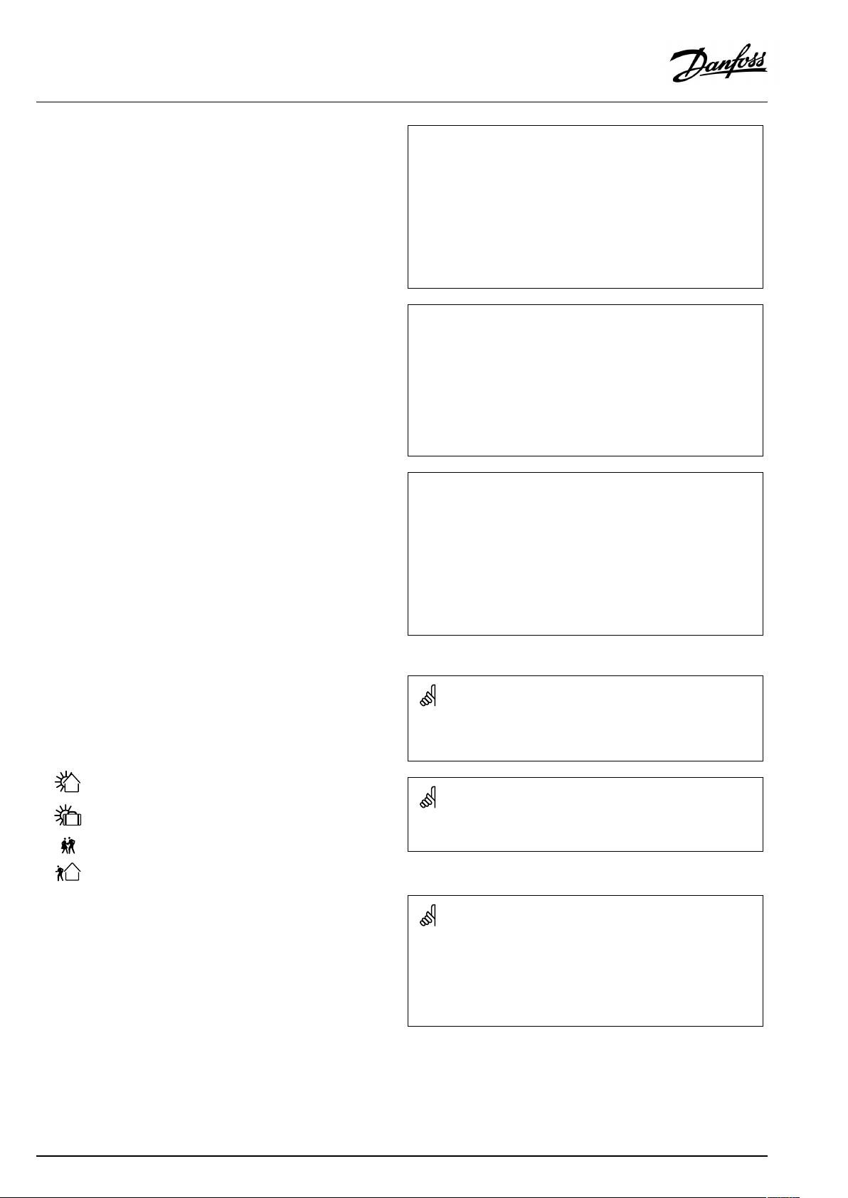
OperatingGuideECLComfort210/310,applicationA267
Holiday,specificcircuit/CommonController
Whensettingoneholidayprograminspecificcircuitandanother
holidayprograminCommonController,aprioritywillbetaken
intoaccount:
1.Comfort
2.Comfort7-23
3.Saving
4.Frostprotection
Holiday,deletingasetperiod:
•ChoosetheScheduleinquestion
•Changethemodeto"Clock"
•Confirm
Example1:
Circuit1:
Holidaysetto"Saving"
CommonController:
Holidaysetto"Comfort"
Result:
Aslongas"Comfort"isactiveinCommonController,circuit1willbein
"Comfort".
Example2:
Circuit1:
Holidaysetto"Comfort"
CommonController:
Holidaysetto"Saving"
Result:
Aslongas"Comfort"isactiveincircuit1,itwillbein"Comfort".
Example3:
Circuit1:
Holidaysetto"Frostprotection"
TheECA30/31cannotoverridetheholidayscheduleofthe
controllertemporarily.
However,itispossibletomakeuseofthefollowingoptionsfrom
theECA30/31whenthecontrollerisinscheduledmode:
Dayoff
Holiday
Relaxing(extendedcomfortperiod)
Goingout(extendedsavingperiod)
CommonController:
Holidaysetto"Saving"
Result:
Aslongas"Saving"isactiveinCommonController,circuit1willbe
in"Saving".
Energy-savingtrick:
Use'Goingout'(theextendedsavingperiod)forairingpurposes(e.g.
forventilatingtheroomsbymeansoffreshairfromopenwindows).
ConnectionsandsetupproceduresforECA30/31:
Seesection'Miscellaneous'.
Quickguide"ECA30/31tooverridemode":
1.GotoECAMENU
2.Movecursorto"Clock"symbol
3.Selectthe"Clock"symbol
4.Chooseandselectoneof4overridefunctions
5.Belowtheoverridesymbol:Sethoursordate
94|©Danfoss|2021.03
AQ026486454993en-010401
Page 95

OperatingGuideECLComfort210/310,applicationA267
6.4Inputoverview
ThissectiondescribesthefunctioningeneralfortheECLComfort
210/296/310series.Theshowndisplaysaretypicalandnot
applicationrelated.Theymightdifferfromthedisplaysinyour
application.
Theinputoverviewislocatedinthecommoncontrollersettings.
Thisoverviewwillalwaysshowyoutheactualtemperaturesinthe
system(read-only).
"Outdooracc.T"means"Accummulatedoutdoortemperature"andis
acalculatedvalueintheECLComfortcontroller.
AQ026486454993en-010401
©Danfoss|2021.03|95
Page 96

OperatingGuideECLComfort210/310,applicationA267
6.5Log
ThissectiondescribesthefunctioningeneralfortheECLComfort
210/296/310series.Theshowndisplaysaretypicalandnot
applicationrelated.Theymightdifferfromthedisplaysinyour
application.
Thelogfunction(temperaturehistory)allowsyoutomonitorthe
logsoftoday,yesterday,thepast2daysaswellasthepast4days
fortheconnectedsensors.
Thereisalogdisplayfortherelevantsensor,showingthemeasured
temperature.
Thelogfunctionisonlyavailableinthe'Commoncontroller
settings'.
Example1:
1daylogforyesterdayshowingthedevelopmentinoutdoor
temperatureduringthepast24hours.
Example2:
Today’slogfortheactualheatingflowtemperatureaswellasthe
desiredtemperature.
Example3:
Yesterday’slogfortheDHWflowtemperatureaswellasthedesired
temperature.
96|©Danfoss|2021.03
AQ026486454993en-010401
Page 97

OperatingGuideECLComfort210/310,applicationA267
6.6Outputoverride
ThissectiondescribesthefunctioningeneralfortheECLComfort
210/296/310series.Theshowndisplaysaretypicalandnot
applicationrelated.Theymightdifferfromthedisplaysinyour
application.
Theoutputoverrideisusedtodisableoneormoreofthecontrolled
components.Thiscouldamongothersbeusefulinaservice
situation.
Action:Purpose:
Choose'MENU'inanyoftheoverview
displays
Confirm
Choosethecircuitselectoratthetop
rightcornerinthedisplay
Confirm
Choosecommoncontrollersettings
Confirm
Choose'Outputoverride'
Confirm
Chooseacontrolledcomponent
Confirm
Adjustthestatusofthecontrolled
component:
Motorizedcontrolvalve:AUTO,STOP ,
CLOSE,OPEN
Pump:AUTO,OFF ,ON
Confirmstatuschange
Examples:
M1,P1etc.
ControlledcomponentsCircuitselector
"Manualcontrol"hashigherprioritythan"Outputoverride".
Whentheselectedcontrolledcomponent(output)isnot‘AUTO’ ,the
ECLComfortcontrollerdoesnotcontrolthecomponentinquestion
(pumpormotorizedcontrolvalvee.g.).Frostprotectionisnotactive.
Remembertochangethestatusbackagainassoonasanoverride
isnotrequiredanylonger.
AQ026486454993en-010401
Whenoutputoverrideofacontrolledcomponentisactivethesymbol
‘!’isshowntotherightofthemodeindicatorintheenduserdisplays.
M3cannotbecontrolledmanuallyasitfollowstheP2output.
ThesettingforP2toONorOFF ,commandsM3toOPENorCLOSE.
©Danfoss|2021.03|97
Page 98

OperatingGuideECLComfort210/310,applicationA267
6.7Keyfunctions
NewapplicationEraseapplication:
ApplicationGivesanoverviewovertheactual
FactorysettingSystemsettings:
Copy
Keyoverview
Removestheexistingapplication.As
soonastheECLkeyisinserted,another
applicationcanbechosen.
applicationintheECLcontroller.Push
thedialagaintoexittheoverview.
Systemsettingsare,amongothers,
communicationset-up,display
brightnessetc.
Usersettings:
Usersettingsare,amongothers,desired
roomtemperature,desiredDHW
temperature,schedules,heatcurve,
limitationvaluesetc.
Gotofactory:
Restoresthefactorysettings.
To:
Copydirection
Systemsettings
Usersettings
Startcopying
GivesanoverviewovertheinsertedECL
key.(Example:A266Ver.2.30).
Turnthedialtoseethesubtypes.Push
thedialagaintoexittheoverview.
Amoredetaileddescriptionofhowtousetheindividual‘Key
functions’canalsobeseenin‘InsertingtheECLapplicationkey’ .
98|©Danfoss|2021.03
AQ026486454993en-010401
Page 99

OperatingGuideECLComfort210/310,applicationA267
The“Keyoverview”doesnotinform—throughECA30/31—about
thesubtypesoftheapplicationkey.
Keyinserted/notinserted,description:
ECLComfort210/310,controllerversionslowerthan1.36:
-
Takeouttheapplicationkey;for20minutes
settingscanbechanged.
-
Powerupthecontrollerwithoutthe
applicationkeyinserted;for20minutes
settingscanbechanged.
ECLComfort210/310,controllerversions1.36andup:
-
Takeouttheapplicationkey;for20minutes
settingscanbechanged.
-
Powerupthecontrollerwithoutthe
applicationkeyinserted;settingscannotbe
changed.
ECLComfort296,controllerversions1.58andup:
-
Takeouttheapplicationkey;for20minutes
settingscanbechanged.
-
Powerupthecontrollerwithoutthe
applicationkeyinserted;settingscannotbe
changed.
AQ026486454993en-010401
©Danfoss|2021.03|99
Page 100

OperatingGuideECLComfort210/310,applicationA267
6.8System
6.8.1ECLversion
In‘ECLversion’youwillalwaysbeabletofindanoverviewofthe
datarelatedtoyourelectroniccontroller.
Pleasehavethisinformationavailableifyouneedtocontactyour
Danfosssalesorganizationconcerningthecontroller.
InformationaboutyourECLApplicationKeycanbefoundin‘Key
functions’and‘Keyoverview’ .
Codeno.:
Hardware:
Software:Software(firmware)versionof
Serialno.:
Productionweek:Weekno.andyear(WW.YYYY)
6.8.2Extension
ECLComfort310/310B:
‘Extension’willofferyouinformationaboutadditionalmodules,if
any.AnexamplecouldbetheECA32module.
TheDanfosssalesandorderno.
forthecontroller
Hardwareversionofthe
controller
thecontroller
Uniquenumberforthe
individualcontroller
Example,ECLversion
6.8.3Ethernet
ECLComfort296/310/310BhaveaModbus/TCPcommunication
interfacethatallowstheECLcontrollertobeconnectedtoan
Ethernetnetwork.ThisallowsremoteaccesstotheECL296/310/
310Bcontrollerbasedonstandardcommunicationinfrastructures.
In‘Ethernet’itispossibletosetuptherequiredIPaddresses.
6.8.4Portalconfig
ECLComfort296/310/310BhaveaModbus/TCPcommunication
interfacethatallowstheECLcontrollertobemonitoredand
controlledviatheECLPortal.
ECLPortalrelatedparametersaresethere.
DocumentationforECLPortal:Seehttps://ecl.portal.danfoss.com
6.8.5M-busconfig
ECLComfort296/310/310BhaveanM-buscommunication
interfacethatallowsenergymeterstobeconnectedasslaves.
M-busrelatedparametersaresethere.
100|©Danfoss|2021.03
AQ026486454993en-010401
 Loading...