

Page 1
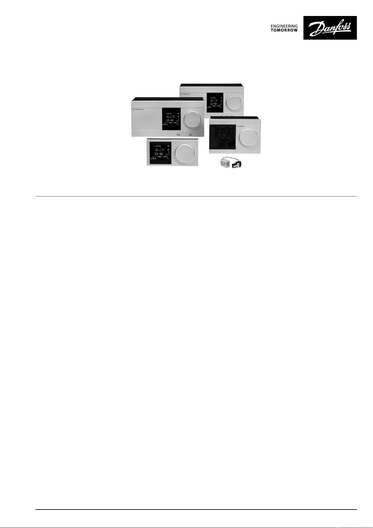
OperatingGuide
ECLComfort210/296/310,applicationA266
1.0TableofContents
1.0TableofContents...............................................1
1.1Importantsafetyandproductinformation.....................2
2.0Installation........................................................6
2.1Beforeyoustart.....................................................6
2.2Identifyingthesystemtype......................................14
2.3Mounting...........................................................15
2.4Placingthetemperaturesensors................................19
2.5Electricalconnections.............................................21
2.6InsertingtheECLApplicationKey..............................30
2.7Checklist............................................................37
2.8Navigation,ECLApplicationKeyA266.........................38
3.0Dailyuse.........................................................58
3.1Howtonavigate...................................................58
3.2Understandingthecontrollerdisplay..........................59
3.3Ageneraloverview:Whatdothesymbolsmean?...........63
3.4Monitoringtemperaturesandsystem
components........................................................64
3.5Influenceoverview................................................65
3.6Manualcontrol.....................................................66
3.7Schedule............................................................67
4.0Settingsoverview............................................68
5.0Settings...........................................................71
5.1IntroductiontoSettings..........................................71
5.2Flowtemperature..................................................72
5.3Roomlimit..........................................................75
5.4Returnlimit.........................................................77
5.5Flow/powerlimit.................................................83
5.6Optimization........................................................88
5.7Controlparameters................................................95
5.8Application.......................................................102
5.9Heatcut-out......................................................110
5.10Alarm..............................................................113
5.11Alarmoverview..................................................119
5.12Anti-bacteria......................................................120
6.0Commoncontrollersettings............................122
6.1Introductionto‘Commoncontrollersettings’..............122
6.2Time&Date.......................................................123
6.3Holiday............................................................124
6.4Inputoverview...................................................126
6.5Log.................................................................127
6.6Outputoverride..................................................128
6.7Keyfunctions.....................................................129
6.8System.............................................................131
7.0Miscellaneous................................................138
7.1ECA30/31setupprocedures.................................138
7.2Overridefunction................................................146
7.3Severalcontrollersinthesamesystem......................149
7.4Frequentlyaskedquestions....................................152
7.5Definitions........................................................155
7.6Type(ID6001),overview.......................................159
7.7Automatic/manualupdateoffirmware.....................160
7.8ParameterIDoverview..........................................161
©Danfoss|2021.06AQ156586461753en-010601|1
Page 2

OperatingGuideECLComfort210/296/310,applicationA266
1.1Importantsafetyandproductinformation
1.1.1Importantsafetyandproductinformation
ThisOperatingGuideisassociatedwithECLApplicationKeyA266
(ordercodeno.087H3800).
TheECLApplicationKeyA266contains4subtypes,allapplicablein
ECLComfort210,296and310:
•A266.1:HeatingandDHW
•A266.2:HeatingandadvancedDHW
•A266.9:HeatinginclusivepressuremonitoringandDHW.
Returntemperaturemonitoringonheatingside.
•A266.10:HeatingandDHW.Returntemperaturemonitoringon
heatingside.
TheA266applicationkeyalsocontainsaFloor(Screed)Drying
Program.Seeseparatedocumentation.(InEnglishandGerman
languageonly).
SeetheInstallationGuide(deliveredwiththeapplicationkey)for
applicationexamplesandelectricalconnections.
ThedescribedfunctionsarerealizedinECLComfort210for
basicsolutionsandinECLComfort296and310foradvanced
solutions,forexampleM-bus,ModbusandEthernet(Internet)
communication.
TheapplicationKeyA266complieswithECLComfort210,ECL
Comfort296andECLComfort310controllersasofsoftware
version1.11(visibleatstart-upofthecontrollerandin'Common
controllersettings'in'System').
UptotwoRemoteControlUnits,ECA30orECA31,canbe
connectedandthebuilt-inroomtemperaturesensorcanbe
utilized.
TogetherwiththeECLComfort310,theadditionalInternalI/O
moduleECA32(ordercodeno.087H3202)canbeusedforextra
datacommunicationtoSCADA:
•Temperature,Pt1000(default)
•0-10voltsignals
Theset-upofinputtypecanbedonebymeansoftheDanfoss
Software"ECLTool".
Navigation:Danfoss.com>Serviceandsupport>Downloads>
Tools>ECLTool.TheURLis:
https://www.danfoss.com/en/service-and-support/downloads
TheInternalI/OmoduleECA32isplacedinthebasepartforECL
Comfort310.
ECLComfort210isavailableas:
•ECLComfort210,230volta.c.(087H3020)
•ECLComfort210B,230volta.c.(087H3030)
ECLComfort296isavailableas:
•ECLComfort296,230volta.c.(087H3000)
ECLComfort310isavailableas:
•ECLComfort310,230volta.c.(087H3040)
•ECLComfort310B,230volta.c.(087H3050)
•ECLComfort310,24volta.c.(087H3044)
2|©Danfoss|2021.06
AQ156586461753en-010601
Page 3
OperatingGuideECLComfort210/296/310,applicationA266
TheB-typeshavenodisplayanddial.TheB-typesareoperatedby
meansoftheRemoteControlunitECA30/31:
•ECA30(087H3200)
•ECA31(087H3201)
BasepartsforECLComfort:
•forECLComfort210,230volta.c.(087H3220)
•forECLComfort296,230volta.c.(087H3240)
•forECLComfort310,230volta.c.and24volta.c(087H3230)
AdditionaldocumentationforECLComfort210,296and310,
modulesandaccessoriesisavailableonhttp://danfoss.com/.
DocumentationforECLPortal:Seehttps://ecl.portal.danfoss.com.
Applicationkeysmightbereleasedbeforealldisplaytextsare
translated.InthiscasethetextisinEnglish.
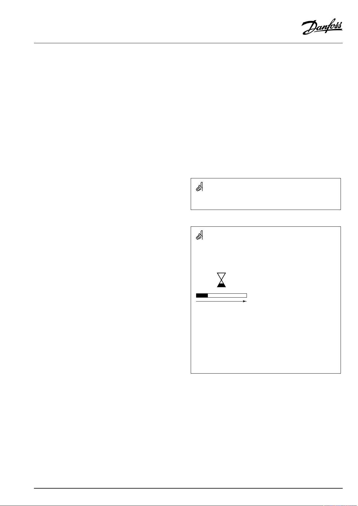
Automaticupdateofcontrollersoftware(firmware):
Thesoftwareofthecontrollerisupdatedautomaticallywhenthekey
isinserted(asofcontrollerversion1.11(ECL210/310)andversion
1.58(ECL296)).Thefollowinganimationwillbeshownwhenthe
softwareisbeingupdated:
Progressbar
Duringupdate:
•DonotremovetheKEY
Ifthekeyisremovedbeforethehour-glassisshown,youhave
tostartafresh.
•Donotdisconnectthepower
Ifthepowerisinterruptedwhenthehour-glassisshown,the
controllerwillnotwork.
•Manualupdateofcontrollersoftware(firmware):
Seethesection"Automatic/manualupdateoffirmware"
AQ156586461753en-010601
©Danfoss|2021.06|3
Page 4
OperatingGuideECLComfort210/296/310,applicationA266
SafetyNote
Toavoidinjuryofpersonsanddamagestothedevice,itisabsolutely
necessarytoreadandobservetheseinstructionscarefully.
Necessaryassembly,start-up,andmaintenanceworkmustbe
performedbyqualifiedandauthorizedpersonnelonly.
Locallegislationsmustberespected.Thiscomprisesalsocable
dimensionsandtypeofisolation(doubleisolatedat230V).
AfusefortheECLComfortinstallationismax.10Atypically.
TheambienttemperaturerangesforECLComfortinoperationare:
ECLComfort210/310:0-55°C
ECLComfort296:0-45°C.
Exceedingthetemperaturerangecanresultinmalfunctions.
Installationmustbeavoidedifthereisariskforcondensation(dew).
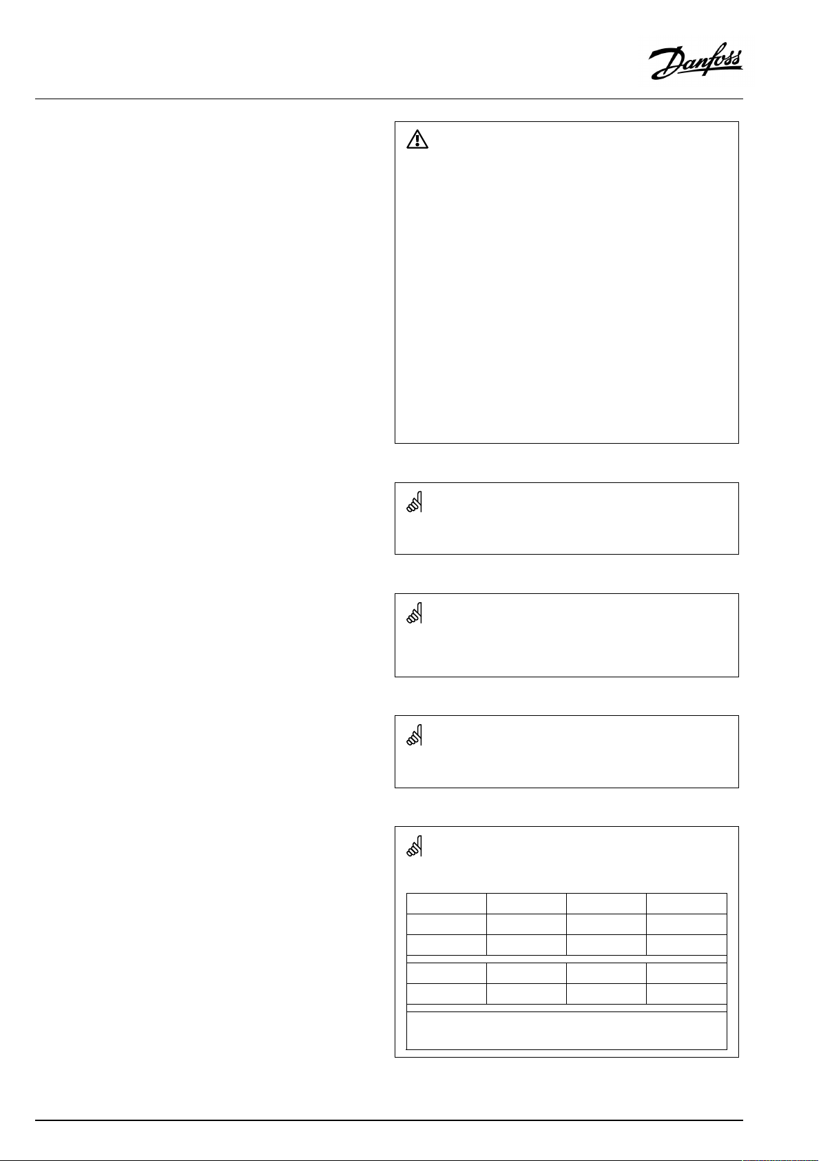
Thewarningsignisusedtoemphasizespecialconditionsthatshould
betakenintoconsideration.
Thissymbolindicatesthatthisparticularpieceofinformationshould
bereadwithspecialattention.
AsthisOperatingGuidecoversseveralsystemtypes,specialsystem
settingswillbemarkedwithasystemtype.Allsystemtypesareshown
inthechapter:'Identifyingyoursystemtype'.
°C(degreesCelsius)isameasuredtemperaturevaluewhereasK
(Kelvin)oftenisusedfortemperaturedifferences.
TheIDno.isuniquefortheselectedparameter.
ExampleFirstdigitSeconddigitLastthreedigits
1117411174
-
Circuit1Parameterno.
4|©Danfoss|2021.06
12174
IfanIDdescriptionismentionedmorethanonce,itmeansthatthere
arespecialsettingsforoneormoresystemtypes.Itwillbemarked
withthesystemtypeinquestion(e.g.12174-A266.9).
1
-
2
Circuit2Parameterno.
174
AQ156586461753en-010601
Page 5
OperatingGuideECLComfort210/296/310,applicationA266
ParametersindicatedwithanIDno.like"1x607"meanauniversal
parameter.
xstandsforcircuit/parametergroup.
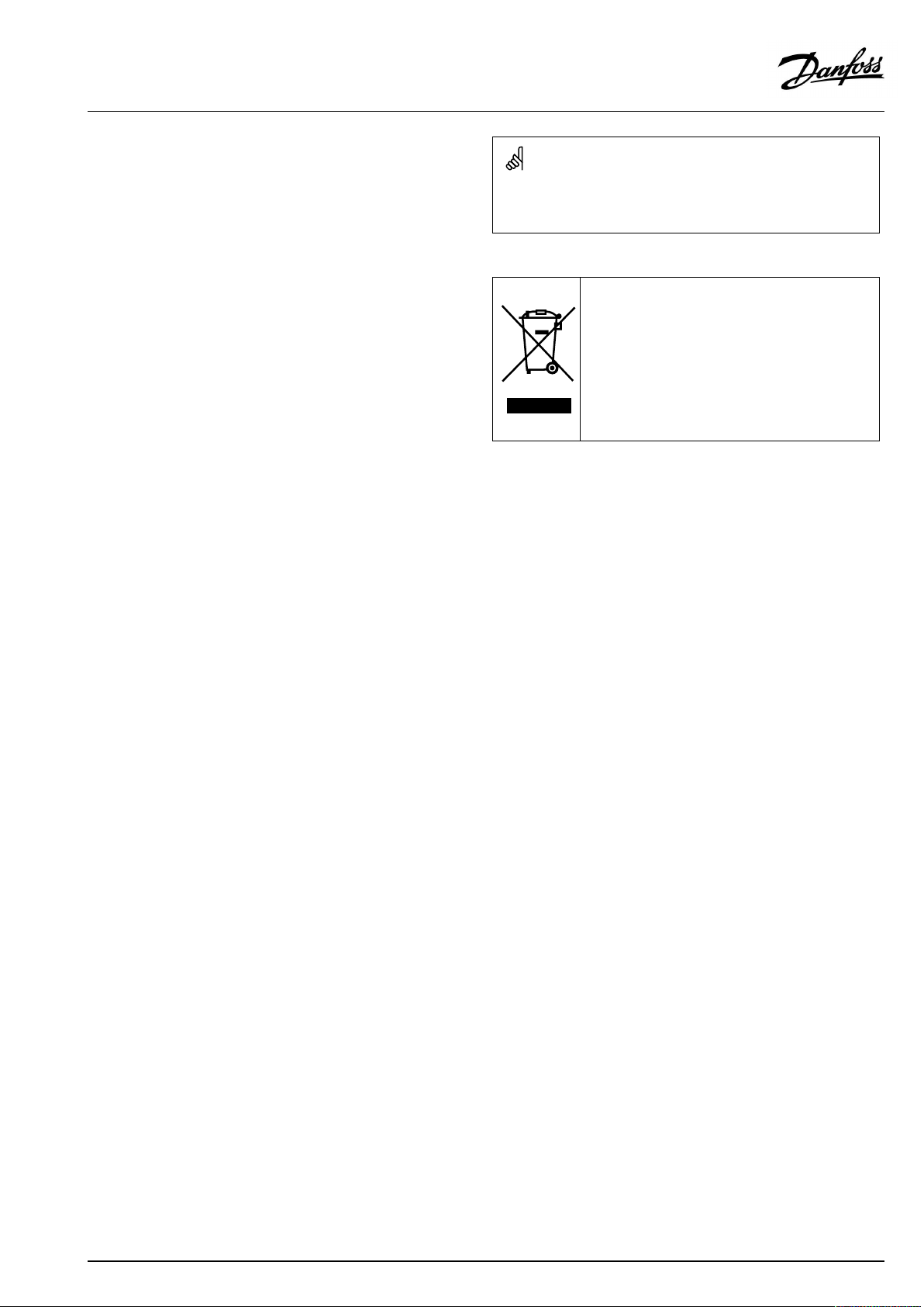
DisposalNote
Thissymbolontheproductindicatesthatitmaynot
bedisposedofashouseholdwaste.
Itmustbehandedovertotheapplicabletake-back
schemefortherecyclingofelectricalandelectronic
equipment.
•Disposeoftheproductthroughchannelsprovided
forthispurpose.
•Complywithalllocalandcurrentlyapplicablelaws
andregulations.
AQ156586461753en-010601
©Danfoss|2021.06|5
Page 6
OperatingGuideECLComfort210/296/310,applicationA266
2.0Installation
2.1Beforeyoustart
TheECLApplicationkeyA266contains4subtypes,A266.1,
A266.2,A266.9andA266.10whicharealmostidentical.
TheapplicationA266.1isveryflexible.Thesearethebasic
principles:
Heating(circuit1):
Typically,theflowtemperatureisadjustedaccordingtoyour
requirements.Theflowtemperaturesensor(S3)isthemost
importantsensor.ThedesiredflowtemperatureatS3iscalculated
intheECLcontroller,basedontheoutdoortemperature(S1)and
thedesiredroomtemperature.Thelowertheoutdoortemperature,
thehigherthedesiredflowtemperature.
Bymeansofaweekschedule,theheatingcircuitcanbein‘Comfort’
or‘Saving’mode(twovaluesforthedesiredroomtemperature).
InSavingmodetheheatingcanbereducedorswitchedofftotally.
Themotorizedcontrolvalve(M2)isopenedgraduallywhenthe
flowtemperatureislowerthanthedesiredflowtemperatureand
viceversa.
Thereturntemperature(S5)canbelimited,forexamplenottobe
toohigh.Ifso,thedesiredflowtemperatureatS3canbeadjusted
(typicallytoalowervalue),thusresultinginagradualclosingof
themotorizedcontrolvalve.Furthermore,thereturntemperature
limitationcanbedependentontheoutdoortemperature.
Typically,thelowertheoutdoortemperature,thehigherthe
acceptedreturntemperature.
Inboiler-basedheatingsupplythereturntemperatureshouldnot
betoolow(sameadjustmentprocedureasabove).
Ifthemeasuredroomtemperaturedoesnotequalthedesired
roomtemperature,thedesiredflowtemperaturecanbeadjusted.
Thecirculationpump,P2,isONatheatdemandoratfrost
protection.
TheheatingcanbeswitchedOFFwhentheoutdoortemperatureis
higherthanaselectablevalue.
Aconnectedfloworenergymeterbasedonpulses(S7)canlimit
thefloworenergytoasetmaximumvalue.Furthermorethe
limitationcanbeinrelationtotheoutdoortemperature.Typically,
thelowertheoutdoortemperature,thehighertheacceptedflow/
power.WhentheA266.1isusedinanECLComfort310theflow/
energysignalcanalternativelycomeasanM-bussignal.
Thefrostprotectionmodemaintainsaselectableflowtemperature,
forexample10°C.
DHW(circuit2):
IfthemeasuredDHWtemperature(S4)islowerthanthedesired
DHWtemperature,themotorizedcontrolvalve(M1)isopened
graduallyandviceversa.
Thereturntemperature(S6)canbelimitedtoafixedvalue.
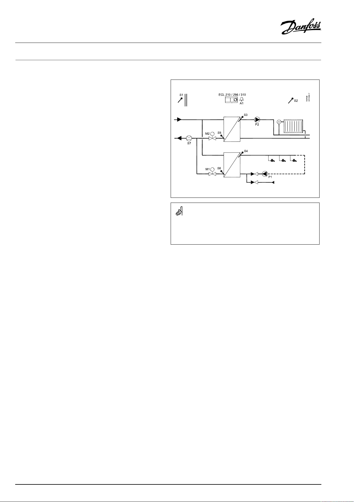
TypicalA266.1application:
M1,M2=3–point/0–10V
Theshowndiagramisafundamentalandsimplifiedexampleanddoes
notcontainallcomponentsthatarenecessaryinasystem.
AllnamedcomponentsareconnectedtotheECLComfortcontroller.
Listofcomponents:
ECL210/296
/310
S1
S2
S3
S4
S5
S6
S7
P1
P2
M1
M2
A1
V1
V2
ElectroniccontrollerECLComfort210,296or310
Outdoortemperaturesensor
(Optional)Roomtemperaturesensor
Flowtemperaturesensor,circuit1
DHWflowtemperaturesensor,circuit2
(Optional)Returntemperaturesensor,circuit1
(Optional)DHWreturntemperaturesensor,circuit2
(Optional)Flow/energymeter(pulsesignal)
Circulationpump,DHW,circuit2
Circulationpump,heating,circuit1
Motorizedcontrolvalve(3-pointcontrolled),circuit2
Motorizedcontrolvalve(3-pointcontrolled),circuit1
Alternative:Thermoactuator(DanfosstypeABV)
Alarm
Motorizedcontrolvalve(0–10V)
(ECLComfort310+ECA32only)
Motorizedcontrolvalve(0–10V)
(ECLComfort310+ECA32only)
Bymeansofaweekschedule,theDHWcircuitcanbein‘Comfort’
or‘Saving’mode(twovaluesforthedesiredDHWtemperature).
6|©Danfoss|2021.06
AQ156586461753en-010601
Page 7

OperatingGuideECLComfort210/296/310,applicationA266
Ananti-bacteriafunctionisavailableforactivationonselected
daysoftheweek.
IfthedesiredDHWtemperaturecannotbereached,theheating
circuitcanbeclosedgraduallytoallowmoreenergytotheDHW
circuit.
A266.1,ingeneral:
AlarmA1(=relay4)canbeactivatediftheactualflowtemperature
differsfromthedesiredflowtemperature.
HolidayprogramsarepresentforHeatingandDHW.Besides,a
holidayprogramispresentfortheentirecontroller.
WhenthesubtypeA266.1hasbeenuploaded,theECLComfort
controllerstartsinmanualmode.Thiscanbeusedforcheckingthe
controlledcomponentsforcorrectfunctionality.
AQ156586461753en-010601
©Danfoss|2021.06|7
Page 8
OperatingGuideECLComfort210/296/310,applicationA266
TheapplicationA266.2isveryflexible.Thesearethebasic
principles:
Heating(circuit1):
Typically,theflowtemperatureisadjustedaccordingtoyour
requirements.Theflowtemperaturesensor(S3)isthemost
importantsensor.ThedesiredflowtemperatureatS3iscalculated
intheECLcontroller,basedontheoutdoortemperature(S1)and
thedesiredroomtemperature.Thelowertheoutdoortemperature,
thehigherthedesiredflowtemperature.
Bymeansofaweekschedule,theheatingcircuitcanbein‘Comfort’
or‘Saving’mode(twovaluesforthedesiredroomtemperature).
InSavingmodetheheatingcanbereducedorswitchedofftotally.
Themotorizedcontrolvalve(M2)isopenedgraduallywhenthe
flowtemperatureislowerthanthedesiredflowtemperatureand
viceversa.
Thereturntemperature(S5)canbelimited,forexamplenottobe
toohigh.Ifso,thedesiredflowtemperatureatS3canbeadjusted
(typicallytoalowervalue),thusresultinginagradualclosingof
themotorizedcontrolvalve.Furthermore,thereturntemperature
limitationcanbedependentontheoutdoortemperature.
Typically,thelowertheoutdoortemperature,thehigherthe
acceptedreturntemperature.
Inboiler-basedheatingsupplythereturntemperatureshouldnot
betoolow(sameadjustmentprocedureasabove).
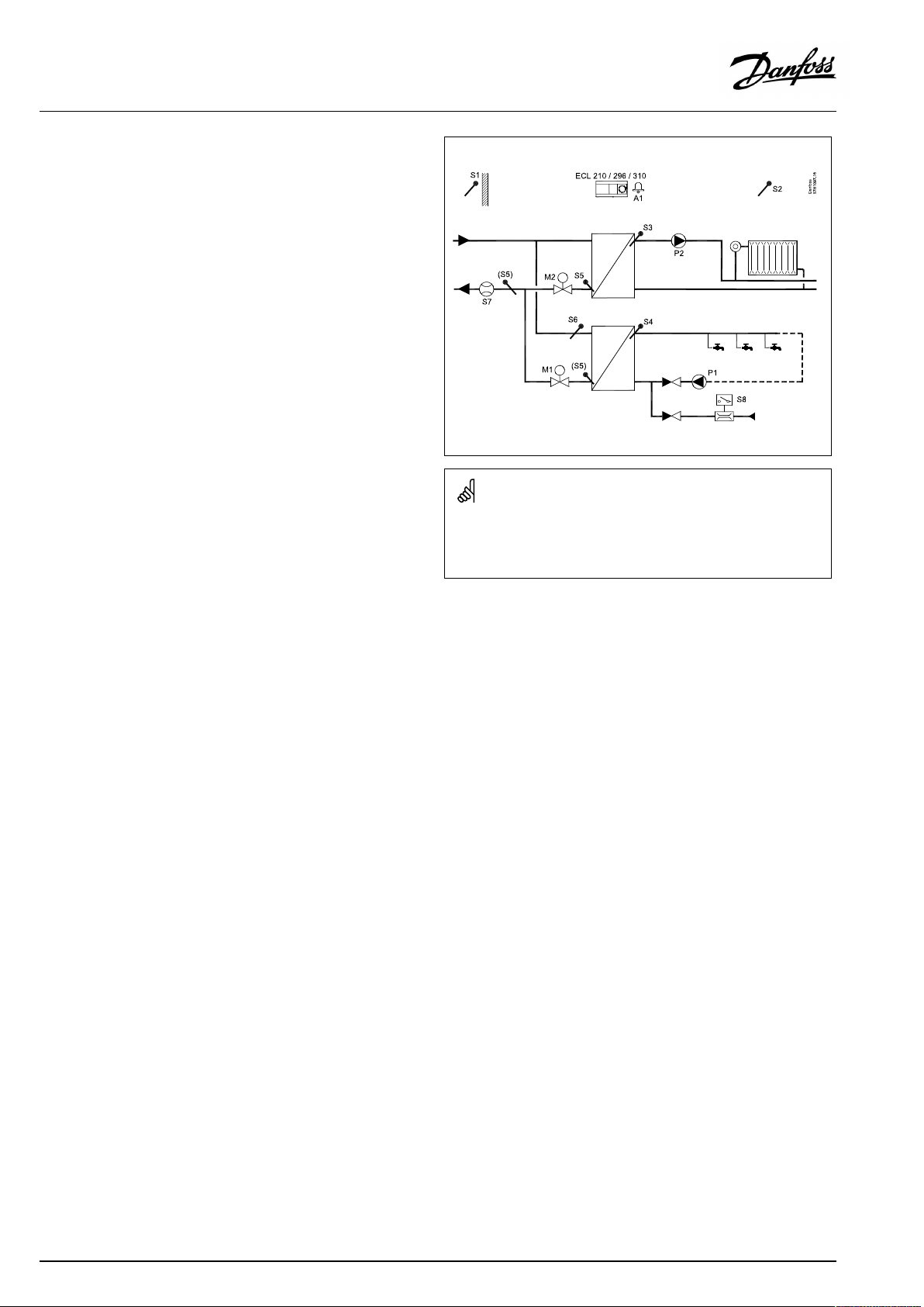
TypicalA266.2application:
M2=3–point/0–10V
Theshowndiagramisafundamentalandsimplifiedexampleanddoes
notcontainallcomponentsthatarenecessaryinasystem.
AllnamedcomponentsareconnectedtotheECLComfortcontroller.
Ifthemeasuredroomtemperaturedoesnotequalthedesired
roomtemperature,thedesiredflowtemperaturecanbeadjusted.
Thecirculationpump,P2,isONatheatdemandoratfrost
protection.
TheheatingcanbeswitchedOFFwhentheoutdoortemperatureis
higherthanaselectablevalue.
Aconnectedfloworenergymeterbasedonpulses(S7)canlimit
thefloworenergytoasetmaximumvalue.Furthermorethe
limitationcanbeinrelationtotheoutdoortemperature.Typically,
thelowertheoutdoortemperature,thehighertheacceptedflow/
power.WhentheA266.2isusedinanECLComfort310theflow/
energysignalcanalternativelycomeasanM-bussignal.
Thefrostprotectionmodemaintainsaselectableflowtemperature,
forexample10°C.
DHW(circuit2):
TheDHWtemperatureatS4ismaintainedat‘Comfort’levelata
DHWdraw-off(DHWtapping)(theflowswitch(S8)isactivated).
IfthemeasuredDHWtemperature(S4)islowerthanthedesired
DHWtemperature,themotorizedcontrolvalve(M1)isopened
graduallyandviceversa.
TheDHWtemperaturecontrolisinrelationtoactualsupply
temperature(S6).Inordertocompensateforthereactiontime,the
motorizedcontrolvalvecanbepre-activatedatthestartofaDHW
draw-off(DHWtapping).Anidletemperaturecanbemaintainedat
eitherS6orS4whenthereisnodraw-off(DHWtapping).
Listofcomponents:
ECL210/296
/310
S1
S2
S3
S4
S5
S6
S7
S8
P1
P2
M1
M2
A1
V2
ElectroniccontrollerECLComfort210,296or310
Outdoortemperaturesensor
(Optional)Roomtemperaturesensor
Flowtemperaturesensor,circuit1
DHWflowtemperaturesensor,circuit2
(Optional)Returntemperaturesensor,circuit1,circuit
2orbothcircuits
(Optional)Supplytemperaturesensor,circuit2
(Optional)Flow/energymeter(pulsesignal)
Flowswitch,DHWdraw-off,circuit2
Circulationpump,DHW,circuit2
Circulationpump,heating,circuit1
Motorizedcontrolvalve(3-pointcontrolled),circuit2
Motorizedcontrolvalve(3-pointcontrolled),circuit1
Alternative:Thermoactuator(DanfosstypeABV
Alarm
Motorizedcontrolvalve(0–10V)
(ECLComfort310+ECA32only)
Thereturntemperature(S5)canbelimitedtoafixedvalue.
Bymeansofaweekschedule,theDHWcircuitcanbein‘Comfort’
or‘Saving’mode(twovaluesforthedesiredDHWtemperature).
8|©Danfoss|2021.06
AQ156586461753en-010601
Page 9

OperatingGuideECLComfort210/296/310,applicationA266
Ananti-bacteriafunctionisavailableforactivationonselected
daysoftheweek.
IfthedesiredDHWtemperaturecannotbereached,theheating
circuitcanbeclosedgraduallytoallowmoreenergytotheDHW
circuit.
A266.2,ingeneral:
AlarmA1(=relay4)canbeactivated:
•iftheactualflowtemperaturediffersfromthedesiredflow
temperature
•ifthetemperatureatS3exceedsanalarmvalue
HolidayprogramsarepresentforHeatingandDHW.Besides,a
holidayprogramispresentfortheentirecontroller.
IfthetemperatureatS3exceedsthealarmvalue'Max.flowT',the
circulationpumpP2isswitchedOFFafterelapseofthe'Delay' .
P2isswitchedONagainwhenthetemperatureatS3getsbelow
alarmvalue.
WhenthesubtypeA266.2hasbeenuploaded,theECLComfort
controllerstartsinmanualmode.Thiscanbeusedforcheckingthe
controlledcomponentsforcorrectfunctionality.
AQ156586461753en-010601
©Danfoss|2021.06|9
Page 10
OperatingGuideECLComfort210/296/310,applicationA266
TheapplicationA266.9isveryflexible.Thesearethebasic
principles:
Heating(circuit1):
Typically,theflowtemperatureisadjustedaccordingtoyour
requirements.Theflowtemperaturesensor(S3)isthemost
importantsensor.ThedesiredflowtemperatureatS3iscalculated
intheECLcontroller,basedontheoutdoortemperature(S1)and
thedesiredroomtemperature.Thelowertheoutdoortemperature,
thehigherthedesiredflowtemperature.
Bymeansofaweekschedule,theheatingcircuitcanbein‘Comfort’
or‘Saving’mode(twovaluesforthedesiredroomtemperature).
InSavingmodetheheatingcanbereducedorswitchedofftotally.
Themotorizedcontrolvalve(M2)isopenedgraduallywhenthe
flowtemperatureislowerthanthedesiredflowtemperatureand
viceversa.
Thereturntemperature(S5)canbelimited,forexamplenottobe
toohigh.Ifso,thedesiredflowtemperatureatS3canbeadjusted
(typicallytoalowervalue),thusresultinginagradualclosingof
themotorizedcontrolvalve.Furthermore,thereturntemperature
limitationcanbedependentontheoutdoortemperature.
Typically,thelowertheoutdoortemperature,thehigherthe
acceptedreturntemperature.
Inboiler-basedheatingsupplythereturntemperatureshouldnot
betoolow(sameadjustmentprocedureasabove).
Thecirculationpump,P2,isONatheatdemandoratfrost
protection.
TheheatingcanbeswitchedOFFwhentheoutdoortemperatureis
higherthanaselectablevalue.
Thesecondaryreturntemperature(S2)isusedformonitoring.The
pressuremeasuring(S7)isusedtoactivateanalarmiftheactual
pressureishigherorlowerthanthechosensettings.
WhentheA266.9isusedinanECLComfort310,aconnected
floworenergymeterbasedonM-bussignalcanlimittheflowor
energytoasetmaximumvalue.Furthermorethelimitationcanbe
inrelationtotheoutdoortemperature.Typically,thelowerthe
outdoortemperature,thehighertheacceptedflow/power.
Thefrostprotectionmodemaintainsaselectableflowtemperature,
forexample10°C.
DHW(circuit2):
IfthemeasuredDHWtemperature(S4)islowerthanthedesired
DHWtemperature,themotorizedcontrolvalve(M1)isopened
graduallyandviceversa.IfthedesiredDHWtemperaturecannot
bereached,theheatingcircuitcanbeclosedgraduallytoallow
moreenergytotheDHWcircuit.
ThereturntemperatureS6canmeasure,formonitoringpurpose,
thereturntemperatureonthesecondaryside.Analternative
positionforS6canbeinthereturnontheprimarysideinorderto
limitthereturntemperaturetoafixedvalue.
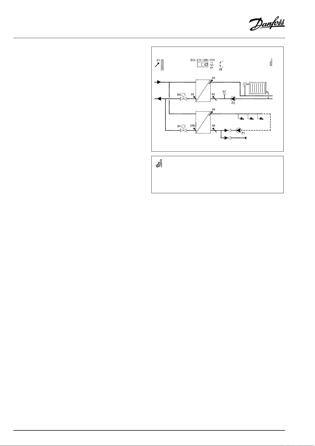
TypicalA266.9application:
M1,M2=3–point/0–10V
Theshowndiagramisafundamentalandsimplifiedexampleanddoes
notcontainallcomponentsthatarenecessaryinasystem.
AllnamedcomponentsareconnectedtotheECLComfortcontroller.
Listofcomponents:
ECL210/296
ElectroniccontrollerECLComfort210,296or310
/310
S1
S2
Outdoortemperaturesensor
(Optional)Returntemperaturesensor,circuit1,for
monitoring
S3
S4
S5
S6
Flowtemperaturesensor,circuit1
DHWflowtemperaturesensor,circuit2
(Optional)Returntemperaturesensor,circuit1
(Optional)Returntemperaturesensor,secondaryside,
circuit2.Alternativeposition:Return,primaryside
S7
S8
P1
P2
M1
M2
A1
V1
(Optional)Pressuretransmitter,circuit1
(Optional)Alarminput
Circulationpump,DHW,circuit2
Circulationpump,heating,circuit1
Motorizedcontrolvalve,circuit2
Motorizedcontrolvalve,circuit1
Alarm
Motorizedcontrolvalve(0–10V)
(ECLComfort310+ECA32only)
V2
Motorizedcontrolvalve(0–10V)
(ECLComfort310+ECA32only)
Bymeansofaweekschedule,theDHWcircuitcanbein‘Comfort’
or‘Saving’mode(twovaluesforthedesiredDHWtemperature).
IfthedesiredDHWtemperaturecannotbereached,theheating
circuitcanbeclosedgraduallytoallowmoreenergytotheDHW
circuit.
Ananti-bacteriafunctionisavailableforactivationonselected
daysoftheweek.
10|©Danfoss|2021.06
AQ156586461753en-010601
Page 11

OperatingGuideECLComfort210/296/310,applicationA266
A266.9,ingeneral:
AlarmA1(=relay4)canbeactivated:
•ifthetemperatureatS3exceedsanalarmvalue
•ifthepressureatS7isnotinsideanacceptablepressurerange
•ifthealarminputS8isactivated
IfthetemperatureatS3exceedsthealarmvalue'Max.flowT',the
circulationpumpP2isswitchedOFFafterelapseofthe'Delay' .
P2isswitchedONagainwhenthetemperatureatS3getsbelow
alarmvalue.
WhenthesubtypeA266.9hasbeenuploaded,theECLComfort
controllerstartsinscheduledmode.
AQ156586461753en-010601
©Danfoss|2021.06|11
Page 12

OperatingGuideECLComfort210/296/310,applicationA266
TheapplicationA266.10isveryflexible.Thesearethebasic
principles:
Heating(circuit1):
Typically,theflowtemperatureisadjustedaccordingtoyour
requirements.Theflowtemperaturesensor(S3)isthemost
importantsensor.ThedesiredflowtemperatureatS3iscalculated
intheECLcontroller,basedontheoutdoortemperature(S1)and
thedesiredroomtemperature.Thelowertheoutdoortemperature,
thehigherthedesiredflowtemperature.
Bymeansofaweekschedule,theheatingcircuitcanbein‘Comfort’
or‘Saving’mode(twovaluesforthedesiredroomtemperature).
InSavingmodetheheatingcanbereducedorswitchedofftotally.
Themotorizedcontrolvalve(M2)isopenedgraduallywhenthe
flowtemperatureislowerthanthedesiredflowtemperatureand
viceversa.
Thereturntemperature(S5)canbelimited,forexamplenottobe
toohigh.Ifso,thedesiredflowtemperatureatS3canbeadjusted
(typicallytoalowervalue),thusresultinginagradualclosingof
themotorizedcontrolvalve.Furthermore,thereturntemperature
limitationcanbedependentontheoutdoortemperature.
Typically,thelowertheoutdoortemperature,thehigherthe
acceptedreturntemperature.
Inboiler-basedheatingsupplythereturntemperatureshouldnot
betoolow(sameadjustmentprocedureasabove).
Thecirculationpump,P2,isONatheatdemandoratfrost
protection.
TheheatingcanbeswitchedOFFwhentheoutdoortemperatureis
higherthanaselectablevalue.
Thesecondaryreturntemperature(S2)isusedformonitoring.
Aconnectedfloworenergymeterbasedonpulses(S7)canlimitthe
floworenergytoasetmaximumvalue.Furthermorethelimitation
canbeinrelationtotheoutdoortemperature.Typically,thelower
theoutdoortemperature,thehighertheacceptedflow/power.
WhentheA266.10isusedinanECLComfort310theflow/energy
signalcanalternativelycomeasanM-bussignal.
Thefrostprotectionmodemaintainsaselectableflowtemperature,
forexample10°C.
DHW(circuit2):
IfthemeasuredDHWtemperature(S4)islowerthanthedesired
DHWtemperature,themotorizedcontrolvalve(M1)isopened
graduallyandviceversa.IfthedesiredDHWtemperaturecannot
bereached,theheatingcircuitcanbeclosedgraduallytoallow
moreenergytotheDHWcircuit.
ThereturntemperatureS6canmeasure,formonitoringpurpose,
thereturntemperatureonthesecondaryside.Analternative
positionforS6canbeinthereturnontheprimarysideinorderto
limitthereturntemperaturetoafixedvalue.
TypicalA266.10application:
M1,M2=3–point/0–10V
Theshowndiagramisafundamentalandsimplifiedexampleanddoes
notcontainallcomponentsthatarenecessaryinasystem.
AllnamedcomponentsareconnectedtotheECLComfortcontroller.
Listofcomponents:
ECL210/296
ElectroniccontrollerECLComfort210,296or310
/310
S1
S2
Outdoortemperaturesensor
(Optional)Returntemperaturesensor,circuit1,for
monitoring
S3
S4
S5
S6
Flowtemperaturesensor,circuit1
DHWflowtemperaturesensor,circuit2
(Optional)Returntemperaturesensor,circuit1
(Optional)Returntemperaturesensor,secondaryside,
circuit2.Alternativeposition:Return,primaryside
S7
S8
P1
P2
M1
M2
A1
V1
(Optional)Flow/energymeter(pulsesignal)
(Optional)Alarminput
Circulationpump,DHW,circuit2
Circulationpump,heating,circuit1
Motorizedcontrolvalve,circuit2
Motorizedcontrolvalve,circuit1
Alarm
Motorizedcontrolvalve(0–10V)
(ECLComfort310+ECA32only)
V2
Motorizedcontrolvalve(0–10V)
(ECLComfort310+ECA32only)
Bymeansofaweekschedule,theDHWcircuitcanbein‘Comfort’
or‘Saving’mode(twovaluesforthedesiredDHWtemperature).
IfthedesiredDHWtemperaturecannotbereached,theheating
circuitcanbeclosedgraduallytoallowmoreenergytotheDHW
circuit.
Ananti-bacteriafunctionisavailableforactivationonselected
daysoftheweek.
12|©Danfoss|2021.06
AQ156586461753en-010601
Page 13
OperatingGuideECLComfort210/296/310,applicationA266
A266.10,ingeneral:
AlarmA1(=relay4)canbeactivated:
•ifthetemperatureatS3exceedsanalarmvalue
•ifthealarminputS8isactivated
IfthetemperatureatS3exceedsthealarmvalue'Max.flowT',the
circulationpumpP2isswitchedOFFafterelapseofthe'Delay' .
P2isswitchedONagainwhenthetemperatureatS3getsbelow
alarmvalue.
WhenthesubtypeA266.10hasbeenuploaded,theECLComfort
controllerstartsinscheduledmode.
A266,ingeneral:
UptotwoRemoteControlUnits,ECA30/31canbeconnectedto
oneECLcontrollerinordertocontroltheECLcontrollerremotely.
Exerciseofcirculationpumpsandcontrolvalveinperiodswithout
heatingdemandcanbearranged.
AdditionalECLComfortcontrollerscanbeconnectedviatheECL
485businordertoutilizecommonoutdoortemperaturesignal,
timeanddatesignals.TheECLcontrollersintheECL485system
canworkinmaster-slavesystem.
Unusedinputcan,bymeansofanoverrideswitch,beusedto
overridethescheduletoafixed'Comfort'or'Saving'mode.
ModbuscommunicationtoaSCADAsystemcanbeestablished.
TheM-busdata(ECLComfort310)canfurthermorebetransferred
totheModbuscommunication.
AlarmA1(=relay4)canbeactivated:
•ifatemperaturesensororitsconnectiondisconnects/short
circuits.(See:Commoncontrollersettings>System>Raw
inputoverview).
Thecontrollerispre-programmedwithfactorysettingsthatareshown
inthe‘ParameterIDoverview’appendix.
AQ156586461753en-010601
©Danfoss|2021.06|13
Page 14
OperatingGuideECLComfort210/296/310,applicationA266
2.2Identifyingthesystemtype
Sketchyourapplication
TheECLComfortcontrollerseriesisdesignedforawiderange
ofheating,domestichot-water(DHW)andcoolingsystemswith
differentconfigurationsandcapacities.Ifyoursystemdiffers
fromthediagramsshownhere,youmaywanttomakeasketch
ofthesystemabouttobeinstalled.Thismakesiteasiertouse
theOperatingGuide,whichwillguideyoustep-by-stepfrom
installationtofinaladjustmentsbeforetheend-usertakesover.
TheECLComfortcontrollerisauniversalcontrollerthatcanbe
usedforvarioussystems.Basedontheshownstandardsystems,
itispossibletoconfigureadditionalsystems.Inthischapteryou
findthemostfrequentlyusedsystems.Ifyoursystemisnotquite
asshownbelow,findthediagramwhichhasthebestresemblance
withyoursystemandmakeyourowncombinations.
SeetheInstallationGuide(deliveredwiththeapplicationkey)for
applicationtypes/sub-types.
Thecirculationpump(s)inheatingcircuit(s)canbeplacedintheflow
aswellasthereturn.Placethepumpaccordingtothemanufacturer’s
specification.
14|©Danfoss|2021.06
AQ156586461753en-010601
Page 15
OperatingGuideECLComfort210/296/310,applicationA266
2.3Mounting
2.3.1MountingtheECLComfortcontroller
SeetheInstallationGuidewhichisdeliveredtogetherwiththe
ECLComfortcontroller.
Foreasyaccess,youshouldmounttheECLComfortcontrollernear
thesystem.
ECLComfort210/296/310canbemounted
•onawall
•onaDINrail(35mm)
ECLComfort296canbemounted
•inapanelcut-out
ECLComfort210canbemountedinanECLComfort310basepart
(forfutureupgrade).
Screws,PGcableglandsandrawlplugsarenotsupplied.
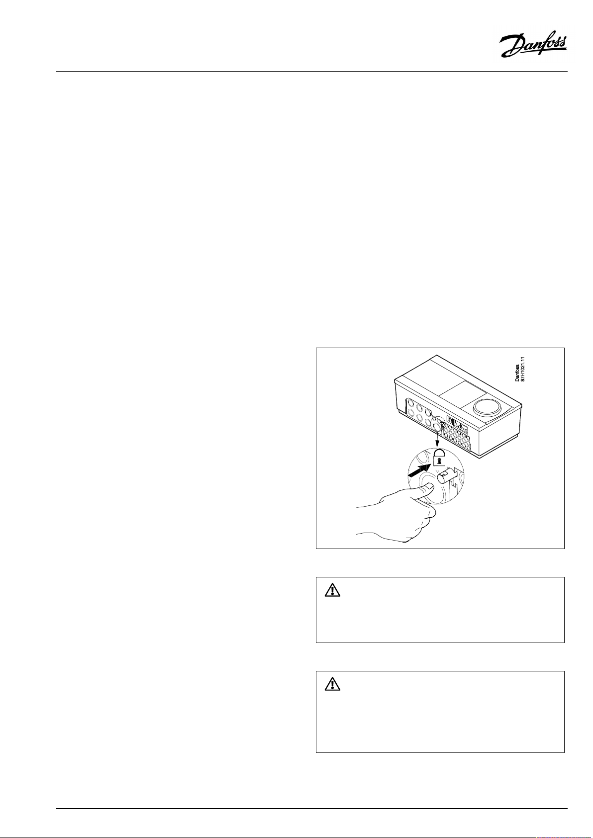
LockingtheECLComfort210/310controller
InordertofastentheECLComfortcontrollertoitsbasepart,secure
thecontrollerwiththelockingpin.
Topreventinjuriestopersonsorthecontroller,thecontrollerhasto
besecurelylockedintothebase.Forthispurpose,pressthelocking
pinintothebaseuntilaclickisheardandthecontrollernolonger
canberemovedfromthebase.
Ifthecontrollerisnotsecurelylockedintothebasepart,thereisarisk
thatthecontrollerduringoperationcanunlockfromthebaseandthe
basewithterminals(andalsothe230Va.c.connections)areexposed.
Topreventinjuriestopersons,alwaysmakesurethatthecontroller
issecurelylockedintoitsbase.Ifthisisnotthecase,thecontroller
shouldnotbeoperated!
AQ156586461753en-010601
©Danfoss|2021.06|15
Page 16
OperatingGuideECLComfort210/296/310,applicationA266
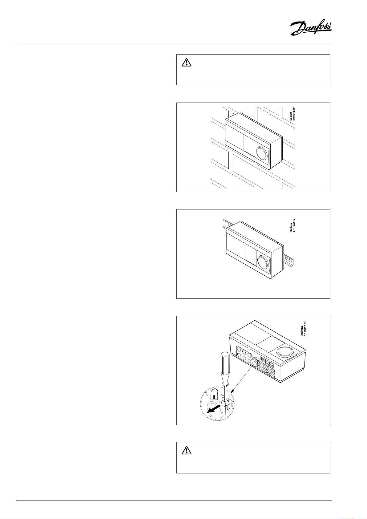
Mountingonawall
Mountthebasepartonawallwithasmoothsurface.Establishthe
electricalconnectionsandpositionthecontrollerinthebasepart.
Securethecontrollerwiththelockingpin.
MountingonaDINrail(35mm)
MountthebasepartonaDINrail.Establishtheelectrical
connectionsandpositionthecontrollerinthebasepart.Secure
thecontrollerwiththelockingpin.
Theeasywaytolockthecontrollertoitsbaseorunlockitistousea
screwdriveraslever.
DismountingtheECLComfortcontroller
Inordertoremovethecontrollerfromthebasepart,pulloutthe
lockingpinbymeansofascrewdriver.Thecontrollercannowbe
removedfromthebasepart.
Theeasywaytolockthecontrollertoitsbaseorunlockitistousea
screwdriveraslever.
16|©Danfoss|2021.06
AQ156586461753en-010601
Page 17
OperatingGuideECLComfort210/296/310,applicationA266
2.3.2MountingtheRemoteControlUnitsECA30/31
Selectoneofthefollowingmethods:
•Mountingonawall,ECA30/31
•Mountinginapanel,ECA30
Screwsandrawlplugsarenotsupplied.
Mountingonawall
MountthebasepartoftheECA30/31onawallwithasmooth
surface.Establishtheelectricalconnections.PlacetheECA30/
31inthebasepart.
BeforeremovingtheECLComfortcontrollerfromthebasepart,ensure
thatthesupplyvoltageisdisconnected.
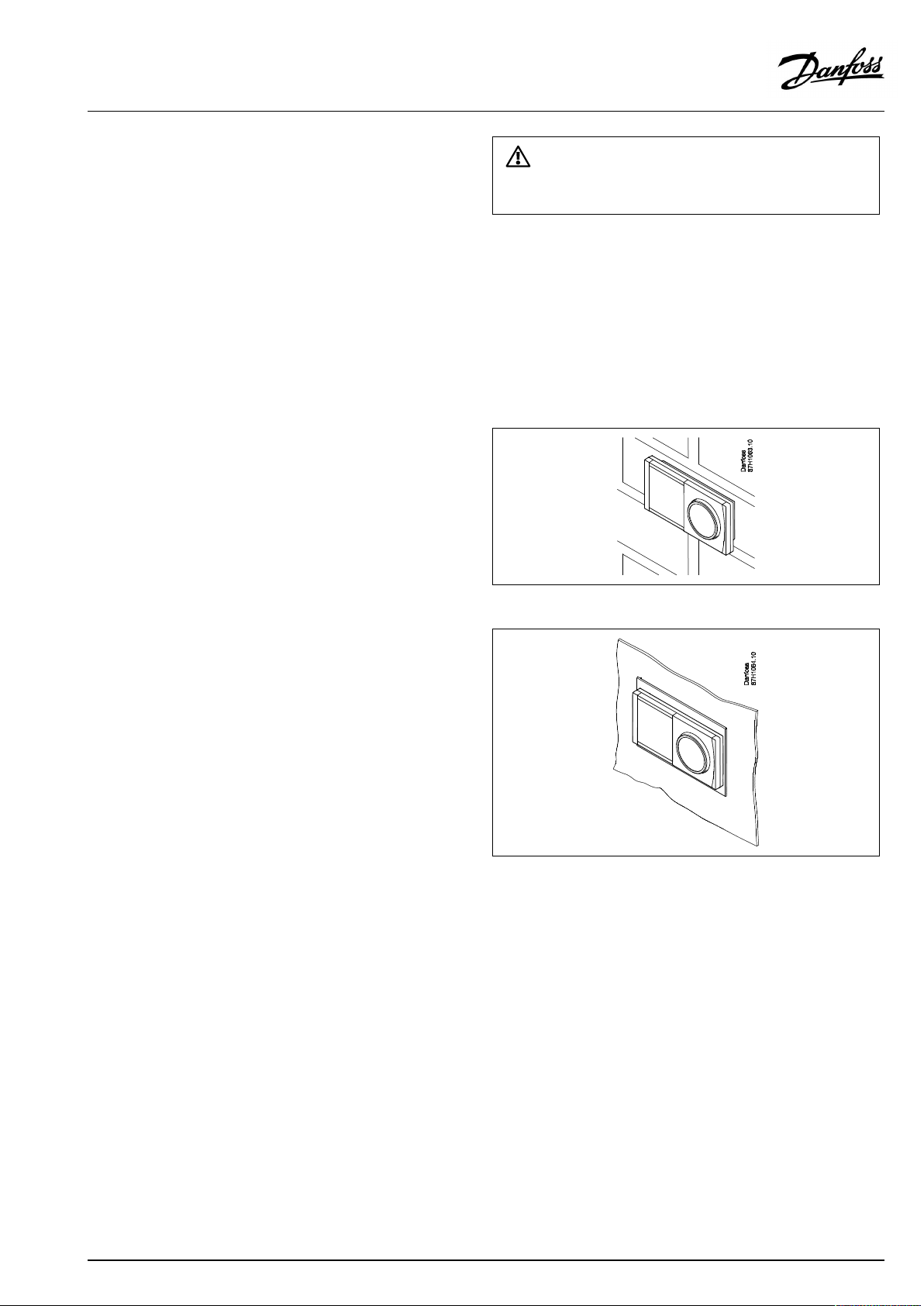
Mountinginapanel
MounttheECA30inapanelusingtheECA30framekit(ordercode
no.087H3236).Establishtheelectricalconnections.Securethe
framewiththeclamp.PlacetheECA30inthebasepart.TheECA
30canbeconnectedtoanexternalroomtemperaturesensor.
TheECA31mustnotbemountedinapanelifthehumidity
functionistobeused.
AQ156586461753en-010601
©Danfoss|2021.06|17
Page 18
OperatingGuideECLComfort210/296/310,applicationA266
2.3.3MountingtheinternalI/OmoduleECA32
MountingoftheinternalI/OmoduleECA32
TheECA32module(ordercodeno.087H3202)mustbeinserted
intotheECLComfort310/310Bbasepartforadditionalinputand
outputsignalsinrelevantapplications.
TheconnectionbetweentheECLComfort310/310BandECA32
isa10-pole(2x5)connector.Theconnectionisautomatically
establishedwhentheECLComfort310/310Bisplacedonthe
basepart.
18|©Danfoss|2021.06
AQ156586461753en-010601
Page 19
OperatingGuideECLComfort210/296/310,applicationA266
2.4Placingthetemperaturesensors
2.4.1Placingthetemperaturesensors
Itisimportantthatthesensorsaremountedinthecorrectposition
inyoursystem.
Thetemperaturesensormentionedbelowaresensorsusedforthe
ECLComfort210/296/310serieswhichnotallwillbeneeded
foryourapplication!
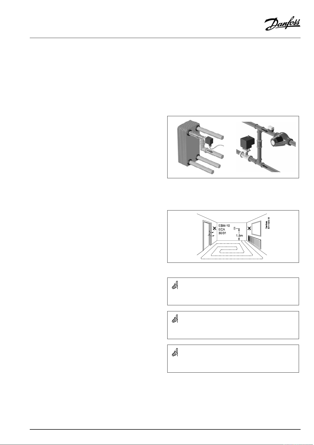
Outdoortemperaturesensor(ESMT)
Theoutdoorsensorshouldbemountedonthatsideofthebuilding
whereitislesslikelytobeexposedtodirectsunshine.Itshouldnot
beplacedclosetodoors,windowsorairoutlets.
Flowtemperaturesensor(ESMU,ESM-11orESMC)
Placethesensormax.15cmfromthemixingpoint.Insystems
withheatexchanger,DanfossrecommendsthattheESMU-typeto
beinsertedintotheexchangerflowoutlet.
Makesurethatthesurfaceofthepipeiscleanandevenwhere
thesensorismounted.
Returntemperaturesensor(ESMU,ESM-11orESMC)
Thereturntemperaturesensorshouldalwaysbeplacedsothatit
measuresarepresentativereturntemperature.
Roomtemperaturesensor
(ESM-10,ECA30/31RemoteControlUnit)
Placetheroomsensorintheroomwherethetemperatureistobe
controlled.Donotplaceitonoutsidewallsorclosetoradiators,
windowsordoors.
Boilertemperaturesensor(ESMU,ESM-11orESMC)
Placethesensoraccordingtotheboilermanufacturer’s
specification.
Airducttemperaturesensor(ESMB-12orESMUtypes)
Placethesensorsothatitmeasuresarepresentativetemperature.
DHWtemperaturesensor(ESMUorESMB-12)
PlacetheDHWtemperaturesensoraccordingtothemanufacturer’s
specification.
Slabtemperaturesensor(ESMB-12)
Placethesensorinaprotectiontubeintheslab.
ESM-11:Donotmovethesensorafterithasbeenfastenedinorderto
avoiddamagetothesensorelement.
ESM-11,ESMCandESMB-12:Useheatconductingpasteforquick
measurementofthetemperature.
ESMUandESMB-12:Usingasensorpockettoprotectthesensorwill,
however,resultinaslowertemperaturemeasurement.
AQ156586461753en-010601
©Danfoss|2021.06|19
Page 20
OperatingGuideECLComfort210/296/310,applicationA266
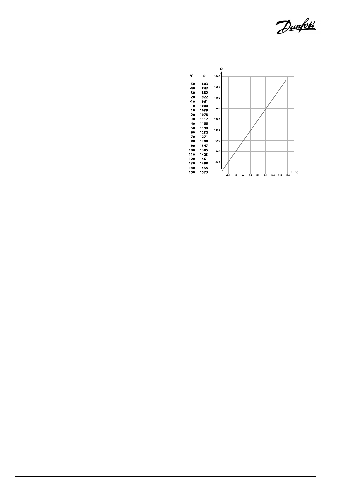
Pt1000temperaturesensor(IEC751B,1000Ω/0°C)
Relationshipbetweentemperatureandohmicvalue:
20|©Danfoss|2021.06
AQ156586461753en-010601
Page 21
OperatingGuideECLComfort210/296/310,applicationA266
2.5Electricalconnections
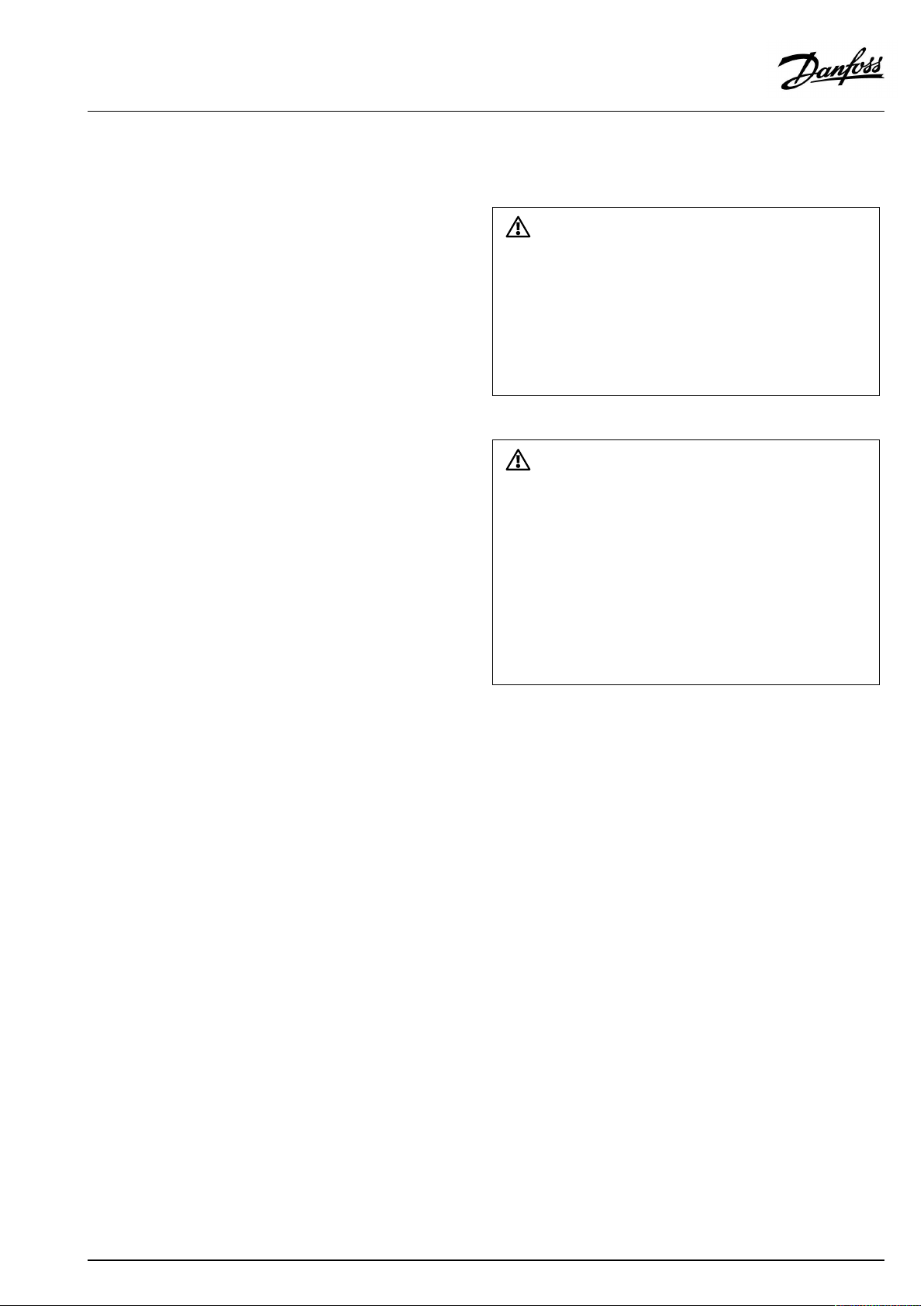
2.5.1Electricalconnections230Va.c.
Warning
ElectricconductorsonPCB(PrintedCircuitBoard)forsupplyvoltage,
relaycontactsandtriacoutputsdonothavemutualsafetydistanceof
minimum6mm.Theoutputsarenotallowedtobeusedasgalvanic
separated(voltfree)outputs.
Ifagalvanicseparatedoutputisneeded,anauxiliaryrelayis
recommended.
24Voltcontrolledunits,forexampleactuators,aretobecontrolledby
meansofECLComfort310,24Voltversion.
SafetyNote
Necessaryassembly,start-up,andmaintenanceworkmustbe
performedbyqualifiedandauthorizedpersonnelonly.
Locallegislationsmustberespected.Thiscomprisesalsocablesize
andisolation(reinforcedtype).
AfusefortheECLComfortinstallationismax.10Atypically.
TheambienttemperaturerangefortheECLComfortinoperationis
0-55°C.Exceedingthistemperaturerangecanresultinmalfunctions.
Installationmustbeavoidedifthereisariskforcondensation(dew).
AQ156586461753en-010601
©Danfoss|2021.06|21
Page 22
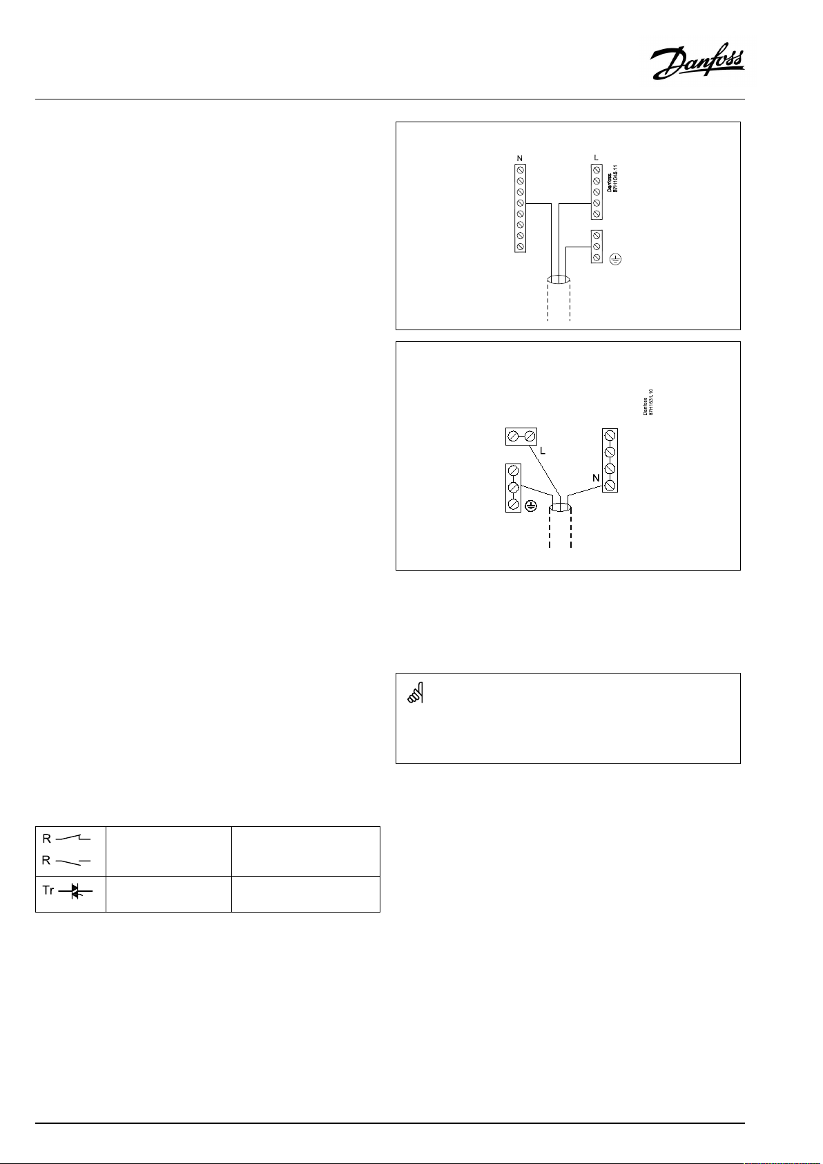
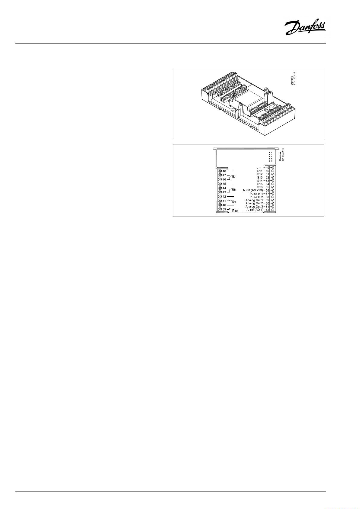
OperatingGuideECLComfort210/296/310,applicationA266
Thecommongroundterminalisusedforconnectionofrelevant
components(pumps,motorizedcontrolvalves).
ECL210/310
ECL296
SeealsotheInstallationGuide(deliveredwiththeapplicationkey)
forapplicationspecificconnections.
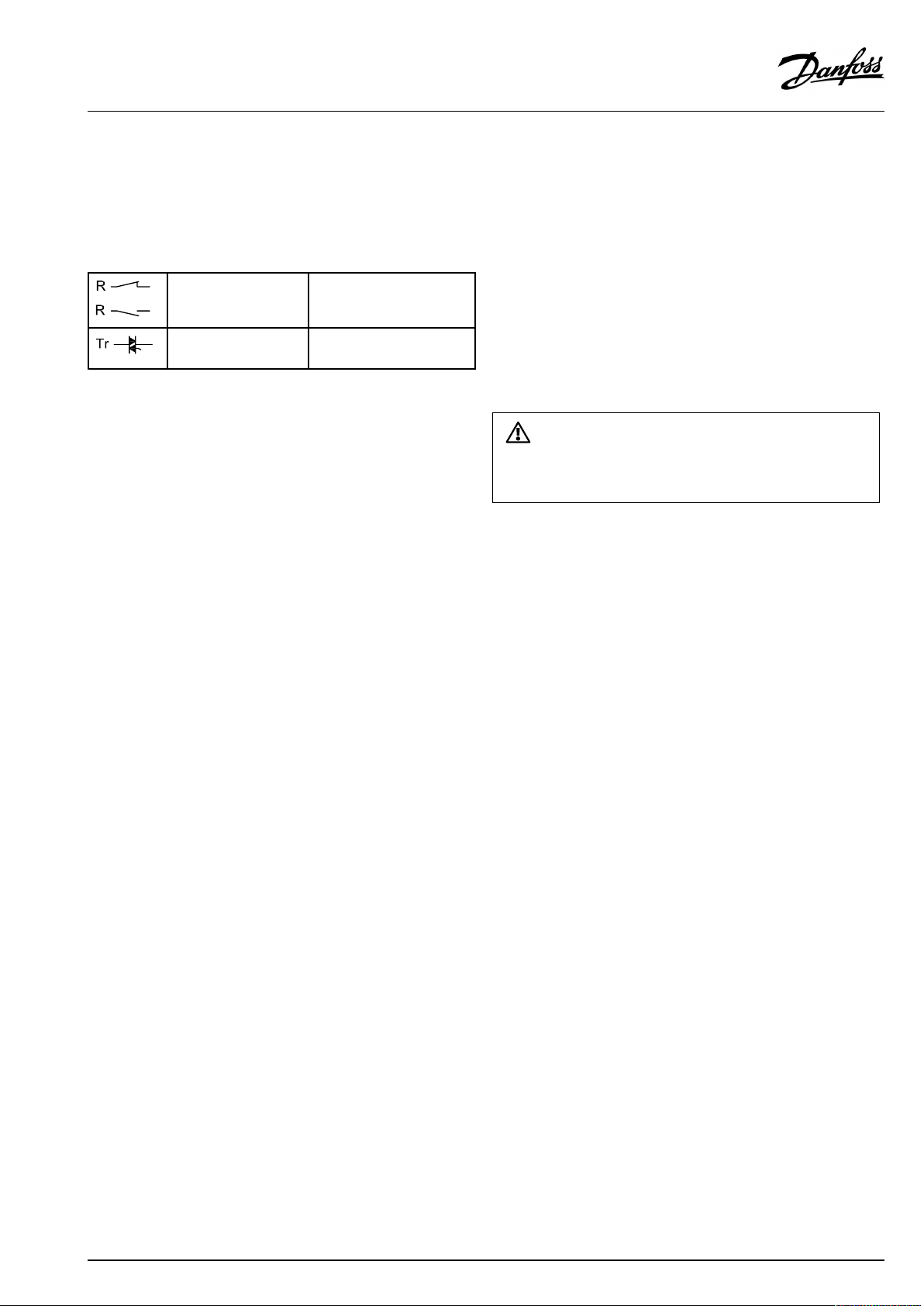
Maximumloadratings:
Relayterminals
4(2)A/230Va.c.
(4Aforohmicload,2Afor
inductiveload)
Triac(=electronic
0,2A/230Va.c.
relay)terminals
Wirecrosssection:0.5-1.5mm²
Incorrectconnectioncandamagetheelectronicoutputs.
Max.2x1.5mm²wirescanbeinsertedintoeachscrewterminal.
22|©Danfoss|2021.06
AQ156586461753en-010601
Page 23
OperatingGuideECLComfort210/296/310,applicationA266
2.5.2Electricalconnections24Va.c.
SeealsotheInstallationGuide(deliveredwiththeapplicationkey)
forapplicationspecificconnections.
Maximumloadratings:
Relayterminals
Triac(=electronic
relay)terminals
4(2)A/24Va.c.
(4Aforohmicload,2Afor
inductiveload)
1A/24Va.c.
Donotconnect230Va.c.poweredcomponentstoa24Va.c.power
suppliedcontrollerdirectly.Useauxilliaryrelays(K)toseparate230
Va.c.from24Va.c.
AQ156586461753en-010601
©Danfoss|2021.06|23
Page 24
OperatingGuideECLComfort210/296/310,applicationA266
2.5.3Electricalconnections,safetythermostats,ingeneral
SeealsotheInstallationGuide(deliveredwiththeapplicationkey)
forapplicationspecificconnections.
WhenSTisactivatedbyahightemperature,thesafetycircuitinthe
motorizedcontrolvalveclosesthevalveimmediately.
WhenST1isactivatedbyahightemperature(theTRtemperature),the
motorizedcontrolvalveisclosedgradually.Atahighertemperature
(theSTtemperature),thesafetycircuitinthemotorizedcontrolvalve
closesthevalveimmediately.
24|©Danfoss|2021.06
AQ156586461753en-010601
Page 25
OperatingGuideECLComfort210/296/310,applicationA266
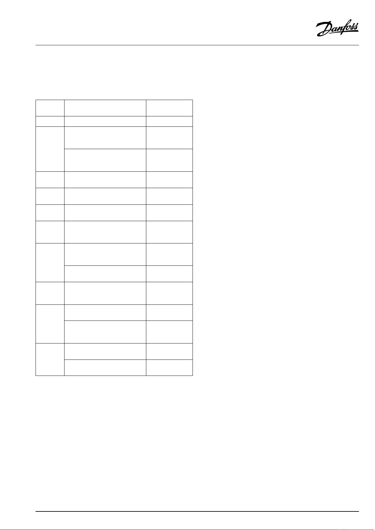
2.5.4Electricalconnections,Pt1000temperaturesensorsandsignals
SeetheInstallationGuide(deliveredwiththeapplicationkey)for
sensorandinputconnections.
Sensor
S1
S2
S3
S4
S5Returntemperaturesensor
(S5)
S6
(S6)
S7
S8
Description
Outdoortemperaturesensor*
A266.1,A266.2:
Roomtemperaturesensor**
Alternative:ECA30/31
A266.9,A266.10:
Returntemperaturesensor
(heating,secondaryside)
Flowtemperaturesensor***
(heating)
Flowtemperaturesensor***
(DHW)
(heating)
A266.2:
Returntemperaturesensor,
alternativepositions
A266.1,A266.9,A266.10:
Returntemperaturesensor
(DHW)
A266.2:
Supplytemperaturesensor
A266.9,A266.10:
Returntemperaturesensor,
alternativeposition
A266.1,A266.2,A266.10:
Flow/heatmeter(pulsesignal)
A266.9:
Pressuretransmitter,0-10Vor
4-20mA
A266.2:
Flowswitch
A266.9,A266.10:
Alarmcontact/switch
Recommended
type
ESMT
A266.1,A266.2:
ESM-10
ESM-11/ESMB/
ESMC/ESMU
ESM-11/ESMB/
ESMC/ESMU
ESM-11/ESMB/
ESMC/ESMU
ESM-11/ESMB/
ESMC/ESMU
ESM-11/ESMB/
ESMC/ESMU
ESM-11/ESMB/
ESMC/ESMU
ESM-11/ESMB/
ESMC/ESMU
ESM-11/ESMB/
ESMC/ESMU
*
Iftheoutdoortemperaturesensorisnotconnectedorthe
cableisshort-circuited,thecontrollerassumesthatthe
outdoortemperatureis0(zero)°C.
**
Onlyforroomtemperaturesensorconnection.Theroom
temperaturesignalcanalsobeavailablefromaRemote
ControlUnit(ECA30/31).SeetheInstallationGuide
(deliveredwiththeapplicationkey)forspecificconnections.
***
Theflowtemperaturesensormustalwaysbeconnected
inordertohavethedesiredfunctionality.Ifthesensoris
notconnectedorthecableisshort-circuited,themotorized
controlvalvecloses(safetyfunction).
AQ156586461753en-010601
©Danfoss|2021.06|25
Page 26

OperatingGuideECLComfort210/296/310,applicationA266
Connectionofflowmeter
SeetheInstallationGuide(deliveredwiththeapplicationkey).
Connectionofflowswitchoralarmcontact/switch
ThealarmcontactactsasaNormallyClosed(NC)contact.The
set-upcanbechangedtoreactonaNormallyOpen(NO)contact.
SeeCircuit1>MENU>Alarm>Digital>Alarmvalue:
0=AlarmforNOcontact
1=AlarmforNCcontact
Connectionofpressuretransmitter
ScaleforconversionofvoltagetopressureissetintheECLComfort.
Thepressuretransmitterispoweredwith12-24Vd.c.
Outputtypes:0-10Vor4-20mA.
4-20mAsignalisconvertedtoa2-10Vsignalbymeansofa500
ohm(0,5W)resistor.
Wirecrosssectionforsensorconnections:Min.0.4mm².
Totalcablelength:Max.200m(allsensorsincl.internalECL485
communicationbus).
Cablelengthsofmorethan200mmaycausenoisesensibility(EMC).
26|©Danfoss|2021.06
AQ156586461753en-010601
Page 27
OperatingGuideECLComfort210/296/310,applicationA266
2.5.5Electricalconnections,ECA30/31
Terminal
ECL
Terminal
ECA30/31
30
31
4
1
322
333
4
5
*
Afteranexternalroomtemperaturesensorhasbeenconnected,
Description
Twistedpair
Twistedpair
Ext.roomtemperature
sensor*
Type
(recomm.)
Cable2x
twistedpair
ESM-10
ECA30/31mustberepowered.
ThecommunicationtotheECA30/31mustbesetupintheECL
Comfortcontrollerin'ECAaddr.'
TheECA30/31mustbesetupaccordingly.
AfterapplicationsetuptheECA30/31isreadyafter2–5min.A
progressbarintheECA30/31isdisplayed.
Iftheactualapplicationcontainstwoheatingcircuits,itispossible
toconnectanECA30/31toeachcircuit.Theelectricalconnections
aredoneinparallel.
Max.2ECA30/31canbeconnectedtoanECLComfort310controller
ortoECLComfort210/296/310controllersinamaster-slavesystem.
SetupproceduresforECA30/31:Seesection‘Miscellaneous’ .
ECAinformationmessage:
‘Applicationreq.newerECA’:
Thesoftware(firmware)ofyourECAdoesnotcomplywiththe
software(firmware)ofyourECLComfortcontroller.Pleasecontact
yourDanfosssalesoffice.
Someapplicationsdonotcontainfunctionsrelatedtoactualroom
temperature.TheconnectedECA30/31willonlyfunctionasremote
control.
AQ156586461753en-010601
©Danfoss|2021.06|27
Page 28
OperatingGuideECLComfort210/296/310,applicationA266
2.5.6Electricalconnections,master/slavesystems
Thecontrollercanbeusedasmasterorslaveinmaster/slave
systemsviatheinternalECL485communicationbus(2xtwisted
paircable).
TheECL485communicationbusisnotcompatiblewiththeECL
businECLComfort110,200,300and301!
Totalcablelength:Max.200m(allsensorsincl.internalECL485
communicationbus).
Cablelengthsofmorethan200mmaycausenoisesensibility(EMC).
Terminal
Description
Type
(recomm.)
30
Commonterminal
+12V*,ECL485communicationbus
31
*OnlyforECA30/31andmaster/
slavecommunication
32
B,ECL485communicationbus
33
A,ECL485communicationbus
Cable2x
twistedpair
ECL485buscable
MaximumrecommendedlengthoftheECL485busiscalculatedlike
this:
Subtract"TotallengthofallinputcablesofallECLcontrollersinthe
master-slavesystem"from200m.
Simpleexamplefortotallengthofallinputcables,3xECL:
1xECL
3xECL
3xECLReturntemp.sensor:
3xECLRoomtemp.sensor:
Total:
Outdoortemp.sensor:
Flowtemp.sensor:
15m
18m
18m
30m
81m
2.5.7Electricalconnections,communication
Electricalconnections,Modbus
ECLComfort210:Non-galvanicisolatedModbusconnections
ECLComfort296:GalvanicisolatedModbusconnections
ECLComfort310:GalvanicisolatedModbusconnections
28|©Danfoss|2021.06
MaximumrecommendedlengthoftheECL485bus:
200-81m=119m
AQ156586461753en-010601
Page 29

OperatingGuideECLComfort210/296/310,applicationA266
2.5.8Electricalconnections,communication
Electricalconnections,M-bus
ECLComfort210:Notimplemented
ECLComfort296:Onboard,non-galvanicisolated.Max.cable
length50m.
ECLComfort310:Onboard,non-galvanicisolated.Max.cable
length50m.
AQ156586461753en-010601
©Danfoss|2021.06|29
Page 30
OperatingGuideECLComfort210/296/310,applicationA266
2.6InsertingtheECLApplicationKey
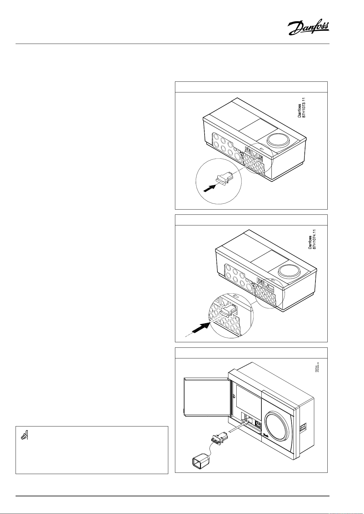
2.6.1InsertingtheECLApplicationKey
TheECLApplicationKeycontains
•theapplicationanditssubtypes,
•currentlyavailablelanguages,
•factorysettings:e.g.schedules,desiredtemperatures,
limitationvaluesetc.Itisalwayspossibletorecoverthefactory
settings,
•memoryforusersettings:specialuser/systemsettings.
Afterhavingpowered-upthecontroller,differentsituationsmight
beexisting:
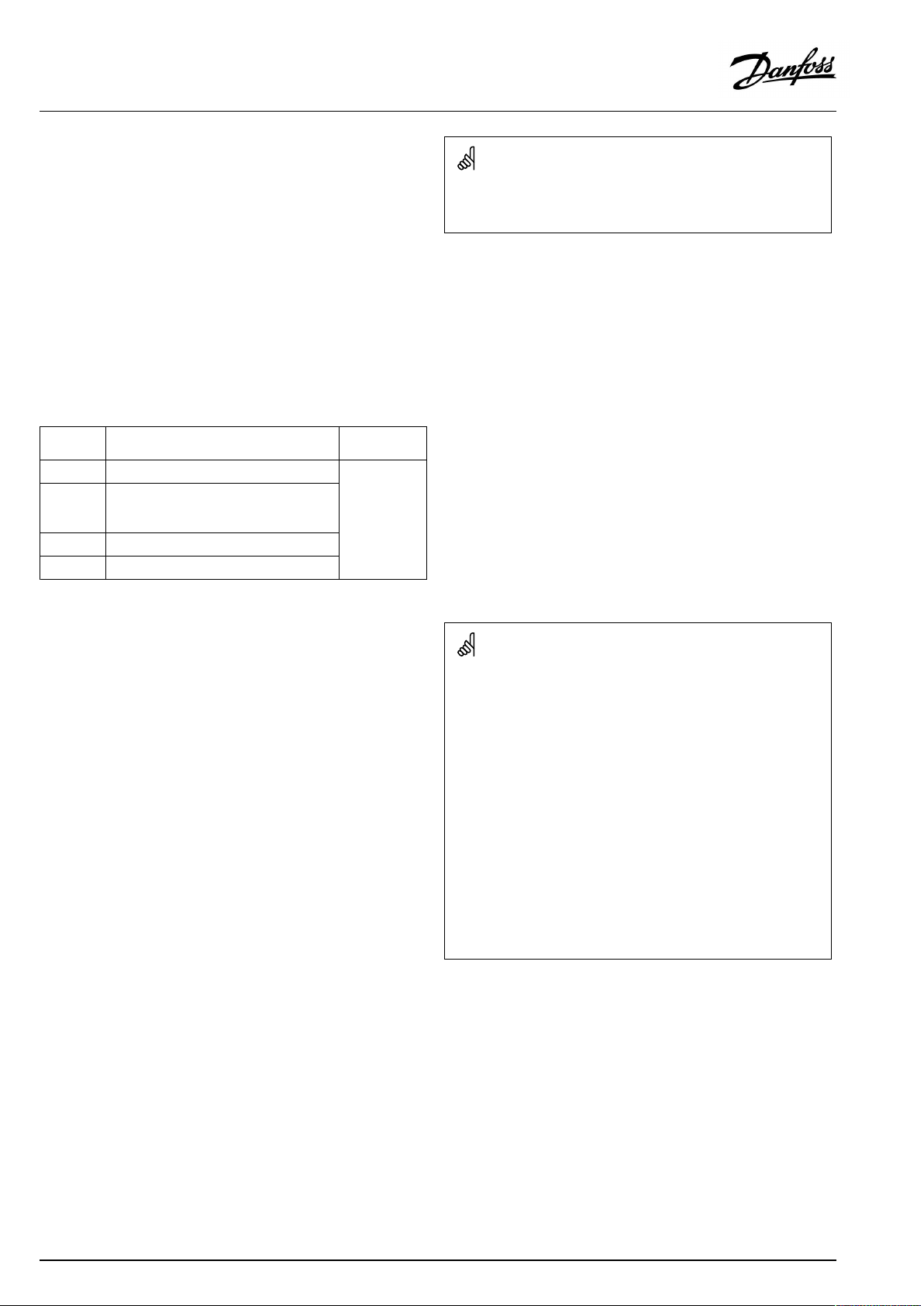
1.Thecontrollerisnewfromthefactory,theECLApplicationKey
isnotinserted.
2.Thecontrolleralreadyrunsanapplication.TheECLApplication
Keyisinserted,buttheapplicationneedstobechanged.
3.Acopyofthecontrollerssettingsisneededforconfiguring
anothercontroller.
ECLComfort210/310
ECLComfort210/310
Usersettingsare,amongothers,desiredroomtemperature,desired
DHWtemperature,schedules,heatcurve,limitationvaluesetc.
Systemsettingsare,amongothers,communicationset-up,display
brightnessetc.
30|©Danfoss|2021.06
ECLComfort296
AQ156586461753en-010601
Page 31

OperatingGuideECLComfort210/296/310,applicationA266
Automaticupdateofcontrollersoftware(firmware):
Thesoftwareofthecontrollerisupdatedautomaticallywhenthekey
isinserted(asofcontrollerversion1.11(ECL210/310)andversion
1.58(ECL296)).Thefollowinganimationwillbeshownwhenthe
softwareisbeingupdated:
Progressbar
Duringupdate:
•DonotremovetheKEY
Ifthekeyisremovedbeforethehour-glassisshown,youhave
tostartafresh.
•Donotdisconnectthepower
Ifthepowerisinterruptedwhenthehour-glassisshown,the
controllerwillnotwork.
•Manualupdateofcontrollersoftware(firmware):
Seethesection"Automatic/manualupdateoffirmware"
The“Keyoverview”doesnotinform—throughECA30/31—about
thesubtypesoftheapplicationkey.
Keyinserted/notinserted,description:
ECLComfort210/310,controllerversionslowerthan1.36:
-
Takeouttheapplicationkey;for20minutes
settingscanbechanged.
-
Powerupthecontrollerwithoutthe
applicationkeyinserted;for20minutes
settingscanbechanged.
ECLComfort210/310,controllerversions1.36andup:
-
Takeouttheapplicationkey;for20minutes
settingscanbechanged.
-
Powerupthecontrollerwithoutthe
applicationkeyinserted;settingscannotbe
changed.
ECLComfort296,controllerversions1.58andup:
-
Takeouttheapplicationkey;for20minutes
settingscanbechanged.
-
Powerupthecontrollerwithoutthe
applicationkeyinserted;settingscannotbe
changed.
AQ156586461753en-010601
©Danfoss|2021.06|31
Page 32
OperatingGuideECLComfort210/296/310,applicationA266
ApplicationKey:Situation1
Thecontrollerisnewfromthefactory,theECLApplicationKey
isnotinserted.
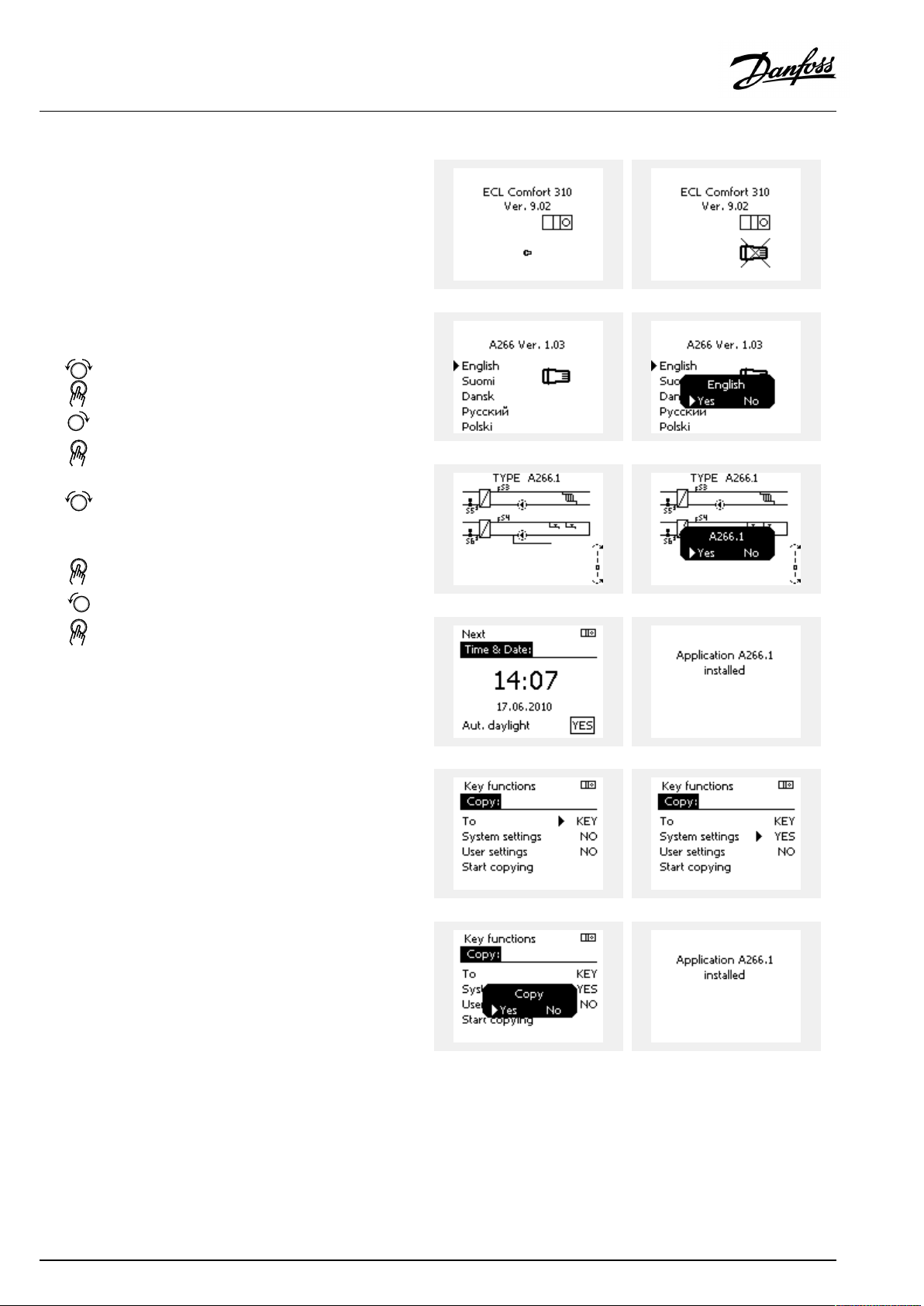
AnanimationfortheECLApplicationKeyinsertionisdisplayed.
InserttheApplicationKey.
ApplicationKeynameandVersionisindicated(example:A266
Ver.1.03).
IftheECLApplicationKeyisnotsuitableforthecontroller,a"cross"
isdisplayedovertheECLApplicationKey-symbol.
Action:Purpose:
Selectlanguage
Confirm
Selectapplication(subtype)
Somekeyshaveonlyoneapplication.
Confirmwith‘Yes’
Set'Time&Date'
Turnandpushthedialtoselectand
change'Hours' ,'Minutes','Date',
'Month'and'Year' .
Choose''Next'
Confirmwith‘Yes’
Goto‘Aut.daylight’
Choosewhether‘ Aut.daylight´*
shouldbeactiveornot
*‘Aut.daylight’istheautomaticchangeoverbetweensummer
andwintertime.
DependingonthecontentsoftheECLApplicationKey,procedure
AorBistakingplace:
A
TheECLApplicationkeycontainsfactorysettings:
Thecontrollerreads/transfersdatafromtheECLApplicationKey
toECLcontroller.
Examples:
YESorNO
Theapplicationisinstalled,andthecontrollerresetsandstartsup.
B
TheECLApplicationkeycontainschangedsystemsettings:
Pushthedialrepeatedly.
’NO’:
’YES*:
Ifthekeycontainsusersettings:
Pushthedialrepeatedly.
‘NO:
‘YES*:
*If‘YES’cannotbechosen,theECLApplicationKeydoesnot
containanyspecialsettings.
Choose‘Startcopying’andconfirmwith'Yes'.
32|©Danfoss|2021.06
OnlyfactorysettingsfromtheECLApplicationKeywill
becopiedtothecontroller.
Specialsystemsettings(differingfromthefactory
settings)willbecopiedtothecontroller.
OnlyfactorysettingsfromtheECLApplicationKeywill
becopiedtothecontroller.
Specialusersettings(differingfromthefactorysettings)
willbecopiedtothecontroller.
AQ156586461753en-010601
Page 33
OperatingGuideECLComfort210/296/310,applicationA266
(Example):
The"i"intheupperrightcornerindicatesthat-besidesthefactory
settings-thesubtypealsocontainsspecialuser/systemssettings.
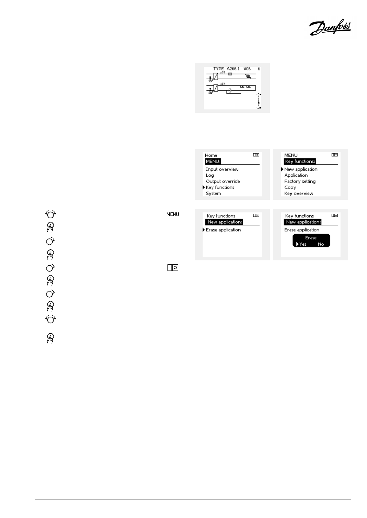
ApplicationKey:Situation2
Thecontrolleralreadyrunsanapplication.TheECLApplication
Keyisinserted,buttheapplicationneedstobechanged.
TochangetoanotherapplicationontheECLApplicationKey,the
currentapplicationinthecontrollermustbeerased(deleted).
BeawarethattheApplicationKeymustbeinserted.
Action:Purpose:
Choose‘MENU’inanycircuit
Confirm
Choosethecircuitselectoratthetop
rightcornerinthedisplay
Confirm
Choose‘Commoncontrollersettings’
Confirm
Choose‘Keyfunctions’
Confirm
Choose‘Eraseapplication’
Confirmwith‘Yes’
Thecontrollerresetsandisreadytobeconfigured.
Followtheproceduredescribedinsituation1.
Examples:
AQ156586461753en-010601
©Danfoss|2021.06|33
Page 34
OperatingGuideECLComfort210/296/310,applicationA266
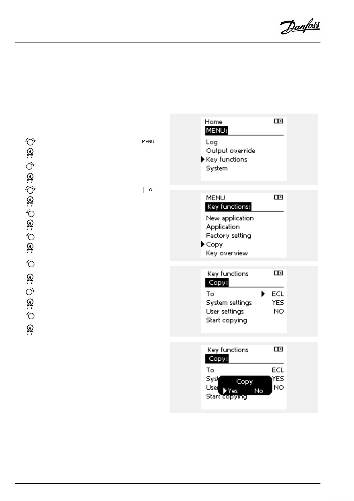
ApplicationKey:Situation3
Acopyofthecontrollerssettingsisneededforconfiguring
anothercontroller.
Thisfunctionisused
•forsaving(backup)ofspecialuserandsystemsettings
•whenanotherECLComfortcontrollerofthesametype(210,
296or310)mustbeconfiguredwiththesameapplicationbut
user/systemsettingsdifferfromthefactorysettings.
HowtocopytoanotherECLComfortcontroller:
Action:Purpose:
Choose‘MENU’
Confirm
Choosethecircuitselectoratthetop
rightcornerinthedisplay
Confirm
Choose'Commoncontrollersettings'
Confirm
Goto‘Keyfunctions’
Confirm
Choose‘Copy’
Confirm
Choose‘To’ .
‘ECL’or‘KEY’willbeindicated.Choose
’ECL’orKEY’
Pushthedialrepeatedlytochoose
copydirection
Choose‘Systemsettings’or‘User
settings’
Pushthedialrepeatedlytochoose
‘Yes’or‘No’in‘Copy’ .Pushtoconfirm.
Choose‘Startcopying’
TheApplicationKeyorthecontroller
isupdatedwithspecialsystemoruser
settings.
Examples:
*
’ECL’or‘KEY’ .
**
‘NO’or‘YES’
*
‘ECL’:
‘KEY’:
**
‘NO’:
‘YES’:
34|©Danfoss|2021.06
DatawillbecopiedfromtheApplicationKeytothe
ECLController.
DatawillbecopiedfromtheECLControllertothe
ApplicationKey.
ThesettingsfromtheECLcontrollerwillnotbecopied
totheApplicationKeyortotheECLComfortcontroller.
Specialsettings(differingfromthefactorysettings)will
becopiedtotheApplicationKeyortotheECLComfort
controller.IfYEScannotbechosen,therearenospecial
settingstobecopied.
AQ156586461753en-010601
Page 35
OperatingGuideECLComfort210/296/310,applicationA266
Language
Atapplicationupload,alanguagemustbeselected.*
IfanotherlanguagethanEnglishisselected,theselectedlanguage
ANDEnglishwillbeuploadedintotheECLcontroller.
ThismakesserviceeasyforEnglishspeakingservicepeople,just
becausetheEnglishlanguagemenuscanbevisiblebychanging
theactualsetlanguageintoEnglish.
(Navigation:MENU>Commoncontroller>System>Language)
Iftheuploadedlanguageisnotsuitable,theapplicationmustbe
erased.UserandSystemsettingscanbesavedontheapplication
keybeforeerasing.
Afternewuploadwithpreferredlanguage,theexistingUserand
Systemsettingscanbeuploaded.
*)
(ECLComfort310,24Volt)Iflanguagecannotbeselected,the
powersupplyisnota.c.(alternatingcurrent).
2.6.2ECLApplicationKey,copyingdata
Generalprinciples
Whenthecontrollerisconnectedandoperating,youcancheck
andadjustallorsomeofthebasicsettings.Thenewsettingscan
bestoredontheKey.
Factorysettingscanalwaysberestored.
HowtoupdatetheECLApplicationKeyaftersettingshave
beenchanged?
AllnewsettingscanbestoredontheECLApplicationKey.
Howtostorefactorysettinginthecontrollerfromthe
ApplicationKey?
PleasereadtheparagraphconcerningApplicationKey,Situation
1:Thecontrollerisnewfromthefactory,theECLApplicationKey
isnotinserted.
HowtostorepersonalsettingsfromthecontrollertotheKey?
PleasereadtheparagraphconcerningApplicationKey,Situation3:
Acopyofthecontrollerssettingsisneededforconfiguringanother
controller
Asamainrule,theECLApplicationKeyshouldalwaysremainin
thecontroller.IftheKeyisremoved,itisnotpossibletochange
settings.
Makeanoteofnewsettingsinthe'Settingsoverview'table.
DonotremovetheECLApplicationKeywhilecopying.Thedataon
theECLApplicationKeycanbedamaged!
ItispossibletocopysettingsfromoneECLComfortcontrollerto
anothercontrollerprovidedthatthetwocontrollersarefromthesame
series(210or310).
Furthermore,whentheECLComfortcontrollerhasbeenuploaded
withanapplicationkey,minimumversion2.44,itispossibletoupload
personalsettingsfromapplicationkeys,minimumversion2.14.
AQ156586461753en-010601
©Danfoss|2021.06|35
Page 36

OperatingGuideECLComfort210/296/310,applicationA266
The“Keyoverview”doesnotinform—throughECA30/31—about
thesubtypesoftheapplicationkey.
Keyinserted/notinserted,description:
ECLComfort210/310,controllerversionslowerthan1.36:
-
Takeouttheapplicationkey;for20minutes
settingscanbechanged.
-
Powerupthecontrollerwithoutthe
applicationkeyinserted;for20minutes
settingscanbechanged.
ECLComfort210/310,controllerversions1.36andup:
-
Takeouttheapplicationkey;for20minutes
settingscanbechanged.
-
Powerupthecontrollerwithoutthe
applicationkeyinserted;settingscannotbe
changed.
ECLComfort296,controllerversions1.58andup:
-
Takeouttheapplicationkey;for20minutes
settingscanbechanged.
-
Powerupthecontrollerwithoutthe
applicationkeyinserted;settingscannotbe
changed.
36|©Danfoss|2021.06
AQ156586461753en-010601
Page 37

OperatingGuideECLComfort210/296/310,applicationA266
2.7Checklist
IstheECLComfortcontrollerreadyforuse?
Makesurethatthecorrectpowersupplyisconnectedtoterminals9and10(230Vor24V).
Makesurethecorrectphaseconditionsareconnected:
230V:Live=terminal9andNeutral=terminal10
24V:SP=terminal9andSN=terminal10
Checkthattherequiredcontrolledcomponents(actuator,pumpetc.)areconnectedtothecorrectterminals.
Checkthatallsensors/signalsareconnectedtothecorrectterminals(see'Electricalconnections').
Mountthecontrollerandswitchonthepower.
IstheECLApplicationKeyinserted(see'InsertingtheApplicationKey').
DoestheECLComfortcontrollercontainanexistingapplication(see'InsertingtheApplicationKey').
Isthecorrectlanguagechosen(see'Language'in'Commoncontrollersettings').
Isthetime&datesetcorrectly(see'Time&Date'in'Commoncontrollersettings').
Istherightapplicationchosen(see'Identifyingthesystemtype').
Checkthatallsettingsinthecontroller(see'Settingsoverview')aresetorthatthefactorysettingscomplywithyour
requirements.
Choosemanualoperation(see'Manualcontrol').Checkthatvalvesopenandclose,andthatrequiredcontrolled
components(pumpetc.)startandstopwhenoperatedmanually.
Checkthatthetemperatures/signalsshowninthedisplaymatchtheactualconnectedcomponents.
Havingcompletedthemanualoperationcheck,choosecontrollermode(scheduled,comfort,savingorfrostprotection).
AQ156586461753en-010601
©Danfoss|2021.06|37
Page 38

OperatingGuideECLComfort210/296/310,applicationA266
2.8Navigation,ECLApplicationKeyA266
Navigation,A266.1,circuit1and2
Home
IDno.
MENU
ScheduleSelectableSelectable
Settings
Flowtemperature
11178
11177
11004
Roomlimit
Returnlimit
Flow/powerlimitActualActual
Optimization
11015
11182
11183
11031
11032
11033
11034
11035
11036
11037
11085
11029
11028
11119
11117
11118
11116
11112
11113
11109
11115
11114
11011
11012
11013
11014
11026
11020
11021
11179
11043
Circuit1,HeatingCircuit2,DHW
Function
Heatcurve
Temp.max.
Temp.min.
DesiredT
Adapt.time
Infl.-max.
Infl.-min.
HighToutX1
LowlimitY1
LowToutX2
HighlimitY2
Infl.-max.
Infl.-min.
Adapt.time
Priority
DHW,ret.Tlimit
Con.T,re.Tlim.
Limit
HighToutX1
LowlimitY1
LowToutX2
HighlimitY2
Adapt.time
Filterconstant
Inputtype
Units
Pulse
Autosaving
Boost
Ramp
Optimizer
Pre-stop
Basedon
Totalstop
Summer,cut-out
Paralleloperation
IDno.
12178
12177
12030
12035
12036
12037
12085
12111
12112
12113
12109
12115
12114
Function
Temp.max.
Temp.min.
Limit
Infl.-max.
Infl.-min.
Adapt.time
Priority
Limit
Adapt.time
Filterconstant
Inputtype
Units
Pulse
38|©Danfoss|2021.06
AQ156586461753en-010601
Page 39

OperatingGuideECLComfort210/296/310,applicationA266
Navigation,A266.1,circuit1andcircuit2continued
Home
MENU
Settings
HolidaySelectableSelectable
Alarm
Controlpar.
Application
Heatcut-out
Anti-bacteria
Temp.monitoring
AlarmoverviewSelectableSelectable
IDno.
11174
11184
11185
11186
11187
11189
11024
11010
11017
11050
11500
11022
11023
11052
11077
11078
11040
11093
11141
11142
11393
11392
11179
11395
11397
11396
11398
11399
11147
11148
11149
11150
Circuit1,HeatingCircuit2,DHW
Function
Motorpr.
Xp
Tn
Mrun
Nz
Min.act.time
Actuator
ECAaddr.
Demandoffset
Pdemand
SenddesiredT
Pexercise
Mexercise
DHWpriority
PfrostT
PheatT
Ppost-run
Frostpr.T
Ext.input
Ext.mode
Sum.start,day
Sum.start,month
Summer,cut-out
Summer,filter
Winterstart,day
Win.start,month
Winter,cut-out
Winter,filter
Upperdifference
Lowerdifference
Delay
Lowesttemp.
IDno.
12173
12174
12184
12185
12186
12187
12189
12024
12500
12022
12023
12077
12078
12040
12093
12141
12142
12147
12148
12149
12150
Function
Autotuning
Motorpr.
Xp
Tn
Mrun
Nz
Min.act.time
Actuator
SenddesiredT
Pexercise
Mexercise
PfrostT
PheatT
Ppost-run
Frostpr.T
Ext.input
Ext.mode
Day
Starttime
Duration
DesiredT
Upperdifference
Lowerdifference
Delay
Lowesttemp.
AQ156586461753en-010601
©Danfoss|2021.06|39
Page 40

OperatingGuideECLComfort210/296/310,applicationA266
Navigation,A266.1,circuit1andcircuit2continued
Home
MENU
InfluenceoverviewDes.flowTReturnlim.Returnlim.
IDno.
Circuit1,HeatingCircuit2,DHW
Function
Roomlim.
Parallelpriority
Flow/powerlim.Flow/powerlim.
HolidayHoliday
Ext.overrideExt.override
ECAoverrideAnti-bacteria
Boost
Ramp
Slave,demand
Heatingcut-out
DHWpriority
SCADAoffsetSCADAoffset
Floordry.,active
IDno.
Function
40|©Danfoss|2021.06
AQ156586461753en-010601
Page 41

OperatingGuideECLComfort210/296/310,applicationA266
Navigation,A266.1,Commoncontrollersettings
Home
MENU
Time&Date
HolidaySelectable
Inputoverview
Log(sensors)
Outputoverride
FloordryingFunctionalheating
OutdoorTLogtoday
RoomT&desiredLogyesterday
HeatingflowT&des.
DHWflowT&des.
HeatreturnT&limit
DHWreturnT&limit
Curingheating
IDno.
Commoncontrollersettings
Function
Selectable
OutdoorT
Outdooracc.T
RoomT
HeatflowT
DHWflowT
HeatreturnT
DHWreturnT
Log2days
Log4days
M1
P1
V1
M2
P2
V2
A1
DesiredflowT
X1
X2
X3
X4
DesiredflowT
X5
X6
X7
X8
RampX5–X6
RampX7–X8
Max.pwr.failure
Afterpowerfail.
Prog.execution
Appl.continue
AQ156586461753en-010601
©Danfoss|2021.06|41
Page 42

OperatingGuideECLComfort210/296/310,applicationA266
Navigation,A266.1,Commoncontrollersettingscontinued
Home
MENU
Keyfunctions
SystemECLversion
Commoncontrollersettings
IDno.
NewapplicationEraseapplication
Application
FactorysettingSystemsettings
Copy
Keyoverview
Extension
Ethernet(ECLComfort296and310
only)
Portalconfig
(ECLComfort296and310only)
Function
Usersettings
Gotofactory
To
Systemsettings
Usersettings
Startcopying
Codeno.
Hardware
Software
Buildno.
Serialno.
Productiondate
Addresstype
ECLportal
Portalstatus
M-busconfig
(ECLComfort296and310only)
EnergyMeters
(ECLComfort296and310only)
Rawinputoverview
Sensoroffset
Alarm
Display
Communication
Language
Portalinfo
5998
Command
5997
Baud
6000
M-busaddress
6002
Scantime
6001
Type
EnergyMeter1....5
S1-S8(ECLComfort210)
S1-S10(ECLComfort310)
S1-S18(ECLComfort310withECA32)
S1...S10offset
32:
Tsensordefect
60058
Backlight
60059
Contrast
38
Modbusaddr.
2048
ECL485addr.
39
Baud
2150
Servicepin
2151
Ext.reset
2050
Language
42|©Danfoss|2021.06
AQ156586461753en-010601
Page 43

OperatingGuideECLComfort210/296/310,applicationA266
Navigation,A266.2,circuit1and2
Home
IDno.
MENU
ScheduleSelectableSelectable
Settings
Flowtemperature
11178
11177
11004
Roomlimit
Returnlimit
Flow/powerlimitActualActual
Optimization
11015
11182
11183
11031
11032
11033
11034
11035
11036
11037
11085
11029
11028
11119
11117
11118
11116
11112
11113
11109
11115
11114
11011
11012
11013
11014
11026
11020
11021
11179
11043
Circuit1,HeatingCircuit2,DHW
Function
Heatcurve
Temp.max.
Temp.min.
DesiredT
Adapt.time
Infl.-max.
Infl.-min.
HighToutX1
LowlimitY1
LowToutX2
HighlimitY2
Infl.-max.
Infl.-min.
Adapt.time
Priority
DHW,ret.Tlimit
Con.T,re.Tlim.
Limit
HighToutX1
LowlimitY1
LowToutX2
HighlimitY2
Adapt.time
Filterconstant
Inputtype
Units
Pulse
Autosaving
Boost
Ramp
Optimizer
Pre-stop
Basedon
Totalstop
Summer,cut-out
Paralleloperation
IDno.
12178
12177
12030
12035
12036
12037
12085
12111
12112
12113
12109
12115
12114
Function
Temp.max.
Temp.min.
Limit
Infl.-max.
Infl.-min.
Adapt.time
Priority
Limit
Adapt.time
Filterconstant
Inputtype
Units
Pulse
AQ156586461753en-010601
©Danfoss|2021.06|43
Page 44

OperatingGuideECLComfort210/296/310,applicationA266
Navigation,A266.2,circuit1andcircuit2continued
Home
MENU
Settings
HolidaySelectableSelectable
Controlpar.
Application
Heatcut-out
Anti-bacteria
IDno.
11174
11184
11185
11186
11187
11189
11024
11010
11017
11050
11500
11022
11023
11052
11077
11078
11040
11093
11141
11142
11393
11392
11179
11395
11397
11396
11398
11399
Circuit1,HeatingCircuit2,DHW
Function
Motorpr.
Xp
Tn
Mrun
Nz
Min.act.time
Actuator
ECAaddr.
Demandoffset
Pdemand
SenddesiredT
Pexercise
Mexercise
DHWpriority
PfrostT
PheatT
Ppost-run
Frostpr.T
Ext.input
Ext.mode
Sum.start,day
Sum.start,month
Summer,cut-out
Summer,filter
Winterstart,day
Win.start,month
Winter,cut-out
Winter,filter
IDno.
12173
12174
12185
12186
12187
12097
12096
12094
12095
12189
12024
12500
12022
12023
12077
12078
12040
12093
12141
12142
Function
Autotuning
Motorpr.
Xpactual
Tn
Mrun
Nz
SupplyT(idle)
Tn(idle)
Opentime
Closetime
Min.act.time
Actuator
SenddesiredT
Pexercise
Mexercise
PfrostT
PheatT
Ppost-run
Frostpr.T
Ext.input
Ext.mode
Day
Starttime
Duration
DesiredT
44|©Danfoss|2021.06
AQ156586461753en-010601
Page 45

OperatingGuideECLComfort210/296/310,applicationA266
Navigation,A266.2,circuit1andcircuit2continued
Home
MENU
Alarm
InfluenceoverviewDes.flowT
Temp.monitoring
Max.temperature
AlarmoverviewSelectableSelectable
IDno.
11147
11148
11149
11150
11079
11080
Circuit1,HeatingCircuit2,DHW
Function
Upperdifference
Lowerdifference
Delay
Lowesttemp.
Max.flowT
Delay
Returnlim.Returnlim.
Roomlim.
Parallelpriority
Flow/powerlim.Flow/powerlim.
HolidayHoliday
Ext.overrideExt.override
ECAoverrideAnti-bacteria
Boost
Ramp
Slave,demand
Heatingcut-out
DHWpriority
SCADAoffsetSCADAoffset
Floordry.,active
IDno.
12147
12148
12149
12150
Function
Upperdifference
Lowerdifference
Delay
Lowesttemp.
AQ156586461753en-010601
©Danfoss|2021.06|45
Page 46

OperatingGuideECLComfort210/296/310,applicationA266
Navigation,A266.2,Commoncontrollersettings
Home
MENU
Time&Date
HolidaySelectable
Inputoverview
Log(sensors)
Outputoverride
FloordryingFunctionalheating
OutdoorTLogtoday
RoomT&desiredLogyesterday
Heatingflow&des.
DHWflow&des.
HeatreturnT&limit
DHWreturnT&limit
SupplyT
Curingheating
IDno.
Commoncontrollersettings
Function
Selectable
OutdoorT
Outdooracc.T
RoomT
HeatflowT
DHWflowT
ReturnT
SupplyT
Flowswitch
Log2days
Log4days
M1
P1
M2
P2
V2
A1
DesiredflowT
X1
X2
X3
X4
DesiredflowT
X5
X6
X7
X8
RampX5–X6
RampX7–X8
Max.pwr.failure
Afterpowerfail.
Prog.execution
Appl.continue
46|©Danfoss|2021.06
AQ156586461753en-010601
Page 47

OperatingGuideECLComfort210/296/310,applicationA266
Navigation,A266.2,Commoncontrollersettingscontinued
Home
MENU
Keyfunctions
SystemECLversion
Commoncontrollersettings
IDno.
NewapplicationEraseapplication
Application
FactorysettingSystemsettings
Copy
Keyoverview
Extension
Ethernet(ECLComfort296and310
only)
Portalconfig
(ECLComfort296and310only)
Function
Usersettings
Gotofactory
To
Systemsettings
Usersettings
Startcopying
Codeno.
Hardware
Software
Buildno.
Serialno.
Productiondate
Addresstype
ECLportal
Portalstatus
M-busconfig
(ECLComfort296and310only)
EnergyMeters
(ECLComfort296and310only)
Rawinputoverview
Sensoroffset
Alarm
Display
Communication
Language
Portalinfo
5998
Command
5997
Baud
6000
M-busaddress
6002
Scantime
6001
Type
EnergyMeter1....5
S1-S8(ECLComfort210)
S1-S10(ECLComfort310)
S1-S18(ECLComfort310withECA32)
S1...S10offset
32:
Tsensordefect
60058
Backlight
60059
Contrast
38
Modbusaddr.
2048
ECL485addr.
39
Baud
2150
Servicepin
2151
Ext.reset
2050
Language
AQ156586461753en-010601
©Danfoss|2021.06|47
Page 48

OperatingGuideECLComfort210/296/310,applicationA266
Navigation,A266.9,circuit1and2
Home
IDno.
MENU
ScheduleSelectableSelectable
Settings
Flowtemperature
11178
11177
11004
Returnlimit
11031
11032
11033
11034
11035
11036
11037
11085
11029
11028
Flow/powerlimitActualActual
11119
11117
11118
11116
11112
11113
11109
11115
Optimization
11011
11012
11013
11014
11026
11021
11179
11043
Circuit1,HeatingCircuit2,DHW
Function
Heatcurve
Temp.max.
Temp.min.
DesiredT
HighToutX1
LowlimitY1
LowToutX2
HighlimitY2
Infl.-max.
Infl.-min.
Adapt.time
Priority
DHW,ret.Tlimit
Con.T,re.Tlim.
Limit
HighToutX1
LowlimitY1
LowToutX2
HighlimitY2
Adapt.time
Filterconstant
Inputtype
Units
Autosaving
Boost
Ramp
Optimizer
Pre-stop
Totalstop
Summer,cut-out
Paralleloperation
IDno.
12178
12177
12030
12035
12036
12037
12111
12112
12113
12109
12115
Function
Temp.max.
Temp.min.
Limit
Infl.-max.
Infl.-min.
Adapt.time
Limit
Adapt.time
Filterconstant
Inputtype
Units
48|©Danfoss|2021.06
AQ156586461753en-010601
Page 49

OperatingGuideECLComfort210/296/310,applicationA266
Navigation,A266.9,circuit1andcircuit2continued
Home
MENU
Settings
Alarm
Controlpar.
Application
Heatcut-out
Anti-bacteria
Pressure
Digital
Max.temperature
AlarmoverviewSelectable
IDno.
11174
11184
11185
11186
11187
11189
11024
11017
11050
11500
11022
11023
11052
11077
11078
11040
11093
11141
11142
11393
11392
11179
11395
11397
11396
11398
11399
11614
11615
11617
11607
11608
11609
11610
11636
11637
11079
11080
Circuit1,HeatingCircuit2,DHW
Function
Motorpr.
Xp
Tn
Mrun
Nz
Min.act.time
Actuator
Demandoffset
Pdemand
SenddesiredT
Pexercise
Mexercise
DHWpriority
PfrostT
PheatT
Ppost-run
Frostpr.T
Ext.input
Ext.mode
Sum.start,day
Sum.start,month
Summer,cut-out
Summer,filter
Winterstart,day
Win.start,month
Winter,cut-out
Winter,filter
Alarmhigh
Alarmlow
Alarmtime-out
LowX
HighX
LowY
HighY
Alarmvalue
Alarmtime-out
Max.flowT
Delay
IDno.
12173
12174
12184
12185
12186
12187
12189
12024
12500
12022
12023
12077
12078
12040
12093
12141
12142
Function
Autotuning
Motorpr.
Xp
Tn
Mrun
Nz
Min.act.time
Actuator
SenddesiredT
Pexercise
Mexercise
PfrostT
PheatT
Ppost-run
Frostpr.T
Ext.input
Ext.mode
Day
Starttime
Duration
DesiredT
AQ156586461753en-010601
©Danfoss|2021.06|49
Page 50

OperatingGuideECLComfort210/296/310,applicationA266
Navigation,A266.9,circuit1andcircuit2continued
Home
MENU
InfluenceoverviewDes.flowTReturnlim.Returnlim.
IDno.
Circuit1,HeatingCircuit2,DHW
Function
ParallelpriorityFlow/powerlimit
Flow/powerlimitExt.override
Ext.overrideAnti-bacteria
Boost
Ramp
Slave,demand
Heatingcut-out
DHWpriority
SCADAoffsetSCADAoffset
Floordry.,active
IDno.
Function
50|©Danfoss|2021.06
AQ156586461753en-010601
Page 51
OperatingGuideECLComfort210/296/310,applicationA266
Navigation,A266.9,Commoncontrollersettings
Home
MENU
Time&Date
Inputoverview
Log(sensors)
Outputoverride
FloordryingFunctionalheating
Heatingflow&des.
Heatingreturn
DHWflow&des.
DHWreturn
OutdoorT
Heatingpressure
Curingheating
IDno.
Commoncontrollersettings
Function
Selectable
OutdoorT
Outdooracc.T
HeatreturnT
HeatflowT
DHWflowT
Prim.returnT
DHWreturnT
Pressure
Digital
Logtoday
Logyesterday
Log2days
Log4days
M1
P1
M2
V1
P2
V2
A1
DesiredflowT
X1
X2
X3
X4
DesiredflowT
X5
X6
X7
X8
RampX5–X6
RampX7–X8
Max.pwr.failure
Afterpowerfail.
Prog.execution
Appl.continue
AQ156586461753en-010601
©Danfoss|2021.06|51
Page 52
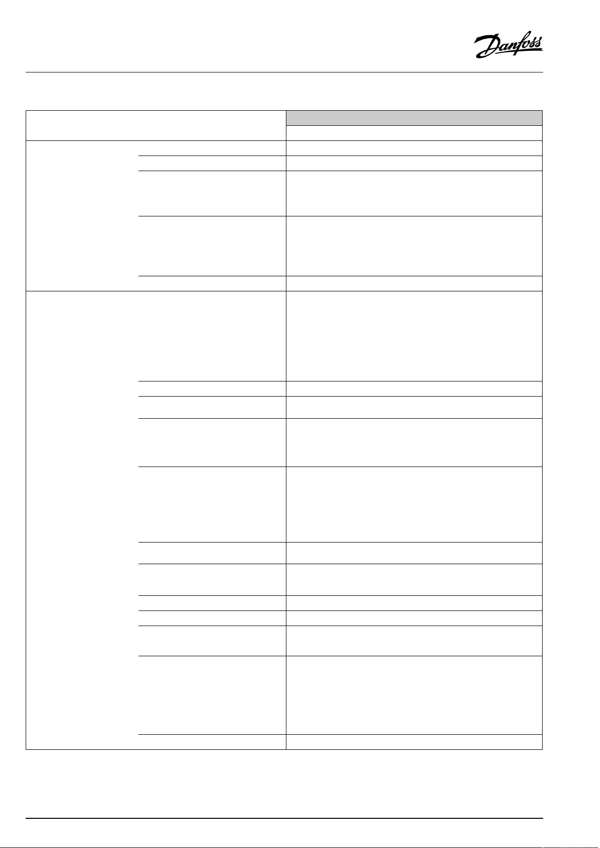
OperatingGuideECLComfort210/296/310,applicationA266
Navigation,A266.9,Commoncontrollersettingscontinued
Home
MENU
Keyfunctions
SystemECLversion
Commoncontrollersettings
IDno.
NewapplicationEraseapplication
Application
FactorysettingSystemsettings
Copy
Keyoverview
Extension
Ethernet(ECLComfort296and310
only)
Portalconfig
(ECLComfort296and310only)
Function
Usersettings
Gotofactory
To
Systemsettings
Usersettings
Startcopying
Codeno.
Hardware
Software
Buildno.
Serialno.
Productiondate
Addresstype
ECLportal
Portalstatus
M-busconfig
(ECLComfort296and310only)
EnergyMeters
(ECLComfort296and310only)
Rawinputoverview
Sensoroffset
Alarm
Display
Communication
Language
Portalinfo
5998
Command
5997
Baud
6000
M-busaddress
6002
Scantime
6001
Type
EnergyMeter1....5
S1-S8(ECLComfort210)
S1-S10(ECLComfort310)
S1-S18(ECLComfort310withECA32)
S1...S10offset
32:
Tsensordefect
60058
Backlight
60059
Contrast
38
Modbusaddr.
2048
ECL485addr.
39
Baud
2150
Servicepin
2151
Ext.reset
2050
Language
52|©Danfoss|2021.06
AQ156586461753en-010601
Page 53

OperatingGuideECLComfort210/296/310,applicationA266
Navigation,A266.10,circuit1and2
Home
IDno.
MENU
ScheduleSelectableSelectable
Settings
Flowtemperature
11178
11177
11004
Returnlimit
11031
11032
11033
11034
11035
11036
11037
11085
11029
11028
Flow/powerlimitActualActual
11119
11117
11118
11116
11112
11113
11109
11115
11114
Optimization
11011
11012
11013
11014
11026
11021
11179
11043
Circuit1,HeatingCircuit2,DHW
Function
Heatcurve
Temp.max.
Temp.min.
DesiredT
HighToutX1
LowlimitY1
LowToutX2
HighlimitY2
Infl.-max.
Infl.-min.
Adapt.time
Priority
DHW,ret.Tlimit
Con.T,re.Tlim.
Limit
HighToutX1
LowlimitY1
LowToutX2
HighlimitY2
Adapt.time
Filterconstant
Inputtype
Units
Pulse
Autosaving
Boost
Ramp
Optimizer
Pre-stop
Totalstop
Summer,cut-out
Paralleloperation
IDno.
12178
12177
12030
12035
12036
12037
12111
12112
12113
12109
12115
12114
Function
Temp.max.
Temp.min.
Limit
Infl.-max.
Infl.-min.
Adapt.time
Limit
Adapt.time
Filterconstant
Inputtype
Units
Pulse
AQ156586461753en-010601
©Danfoss|2021.06|53
Page 54

OperatingGuideECLComfort210/296/310,applicationA266
Navigation,A266.10,circuit1andcircuit2continued
Home
MENU
Settings
AlarmDigital
IDno.
Controlpar.
11174
11184
11185
11186
11187
11189
11024
Application
Heatcut-out
Anti-bacteria
Max.temperature
AlarmoverviewSelectable
11017
11050
11500
11022
11023
11052
11077
11078
11040
11093
11141
11142
11393
11392
11179
11395
11397
11396
11398
11399
11636
11637
11079
11080
Circuit1,HeatingCircuit2,DHW
Function
Motorpr.
Xp
Tn
Mrun
Nz
Min.act.time
Actuator
Demandoffset
Pdemand
SenddesiredT
Pexercise
Mexercise
DHWpriority
PfrostT
PheatT
Ppost-run
Frostpr.T
Ext.input
Ext.mode
Sum.start,day
Sum.start,month
Summer,cut-out
Summer,filter
Winterstart,day
Win.start,month
Winter,cut-out
Winter,filter
Alarmvalue
Alarmtime-out
Max.flowT
Delay
IDno.
12173
12174
12184
12185
12186
12187
12189
12024
12500
12022
12023
12077
12078
12040
12093
12141
12142
Function
Autotuning
Motorpr.
Xp
Tn
Mrun
Nz
Min.act.time
Actuator
SenddesiredT
Pexercise
Mexercise
PfrostT
PheatT
Ppost-run
Frostpr.T
Ext.input
Ext.mode
Day
Starttime
Duration
DesiredT
54|©Danfoss|2021.06
AQ156586461753en-010601
Page 55

OperatingGuideECLComfort210/296/310,applicationA266
Navigation,A266.10,circuit1andcircuit2continued
Home
MENU
InfluenceoverviewDes.flowTReturnlim.Returnlim.
IDno.
Circuit1,HeatingCircuit2,DHW
Function
ParallelperiorityFlow/powerlimit
Flow/powerlimitExt.override
Ext.overrideAnti-bacteria
Boost
Ramp
Slave,demand
Heatingcut-out
DHWpriority
SCADAoffsetSCADAoffset
Floordry.,active
IDno.
Function
AQ156586461753en-010601
©Danfoss|2021.06|55
Page 56

OperatingGuideECLComfort210/296/310,applicationA266
Navigation,A266.10,Commoncontrollersettings
Home
MENU
Time&Date
Inputoverview
Log(sensors)
Outputoverride
FloordryingFunctionalheating
Heatingflow&des.
Heatingreturn
DHWflow&des.
DHWreturn
OutdoorT
Curingheating
IDno.
Commoncontrollersettings
Function
Selectable
OutdoorT
Outdooracc.T
HeatreturnT
HeatflowT
DHWflowT
Prim.returnT
DHWreturnT
Digital
Logtoday
Logyesterday
Log2days
Log4days
M1
P1
M2
V1
P2
V2
A1
DesiredflowT
X1
X2
X3
X4
DesiredflowT
X5
X6
X7
X8
RampX5–X6
RampX7–X8
Max.pwr.failure
Afterpowerfail.
Prog.execution
Appl.continue
56|©Danfoss|2021.06
AQ156586461753en-010601
Page 57
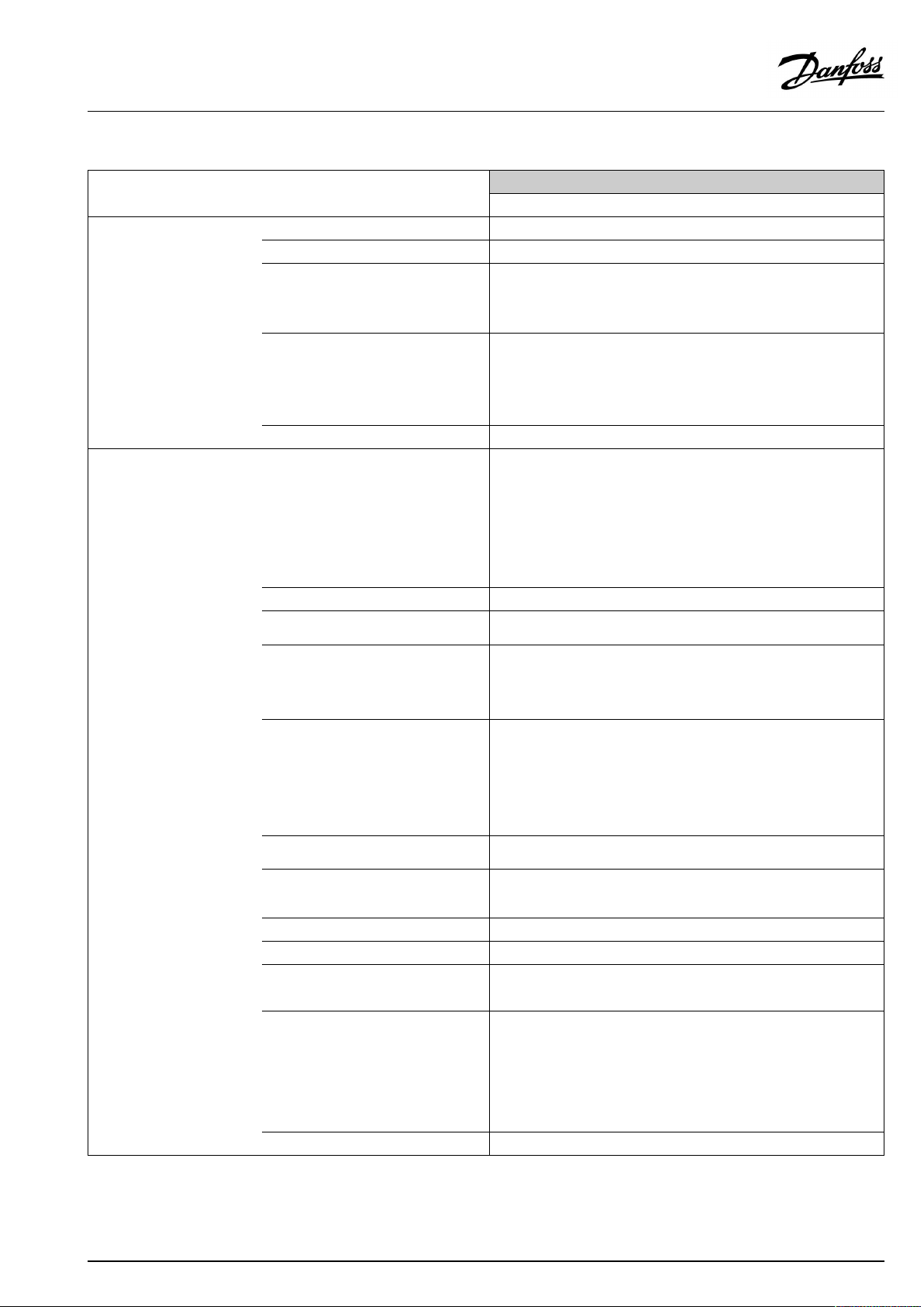
OperatingGuideECLComfort210/296/310,applicationA266
Navigation,A266.10,Commoncontrollersettingscontinued
Home
MENU
Keyfunctions
SystemECLversion
Commoncontrollersettings
IDno.
NewapplicationEraseapplication
Application
FactorysettingSystemsettings
Copy
Keyoverview
Extension
Ethernet(ECLComfort296and310
only)
Portalconfig
(ECLComfort296and310only)
Function
Usersettings
Gotofactory
To
Systemsettings
Usersettings
Startcopying
Codeno.
Hardware
Software
Buildno.
Serialno.
Productiondate
Addresstype
ECLportal
Portalstatus
M-busconfig
(ECLComfort296and310only)
EnergyMeters
(ECLComfort296and310only)
Rawinputoverview
Sensoroffset
Alarm
Display
Communication
Language
Portalinfo
5998
Command
5997
Baud
6000
M-busaddress
6002
Scantime
6001
Type
EnergyMeter1....5
S1-S8(ECLComfort210)
S1-S10(ECLComfort310)
S1-S18(ECLComfort310withECA32)
S1...S10offset
32:
Tsensordefect
60058
Backlight
60059
Contrast
38
Modbusaddr.
2048
ECL485addr.
39
Baud
2150
Servicepin
2151
Ext.reset
2050
Language
AQ156586461753en-010601
©Danfoss|2021.06|57
Page 58

OperatingGuideECLComfort210/296/310,applicationA266
3.0Dailyuse
3.1Howtonavigate
Younavigateinthecontrollerbyturningthedialleftorrightto
thedesiredposition().
Thedialhasabuilt-inaccellerator.Thefasteryouturnthedial,the
fasteritreachesthelimitsofanywidesettingrange.
Thepositionindicatorinthedisplay(
youare.
Pushthedialtoconfirmyourchoices().
Thedisplayexamplesarefromatwo-circuitapplication:One
heatingcircuit()andonedomestichot-water(DHW)circuit().
Theexamplesmightdifferfromyourapplication.
)willalwaysshowyouwhere
ExampleshowsECL210/310
Heatingcircuit():DHWcircuit();
Somegeneralsettingswhichapplytotheentirecontrollerare
locatedinaspecificpartofthecontroller.
Toenter‘Commoncontrollersettings’:
Action:Purpose:
Choose‘MENU’inanycircuit
Confirm
Choosethecircuitselectoratthetop
rightcornerinthedisplay
Confirm
Choose‘Commoncontrollersettings’
Confirm
Examples:
Circuitselector
58|©Danfoss|2021.06
AQ156586461753en-010601
Page 59

OperatingGuideECLComfort210/296/310,applicationA266
3.2Understandingthecontrollerdisplay
ThissectiondescribesthefunctioningeneralfortheECLComfort
210/296/310series.Theshowndisplaysaretypicalandnot
applicationrelated.Theymightdifferfromthedisplaysinyour
application.
Choosingafavoritedisplay
Yourfavoritedisplayisthedisplayyouhavechosenasthedefault
display.Thefavoritedisplaywillgiveyouaquickoverviewofthe
temperaturesorunitsthatyouwanttomonitoringeneral.
Ifthedialhasnotbeenactivatedfor20min.,thecontrollerwill
reverttotheoverviewdisplayyouhavechosenasfavorite.
Toshiftbetweendisplays:Turnthedialuntilyoureachthedisplay
selector(
turntochooseyourfavoriteoverviewdisplay.Pushthedialagain.
)atthebottomrightsideofthedisplay.Pushthedialand
Heatingcircuit
Overviewdisplay1informsabout:
actualoutdoortemperature,controllermode,
actualroomtemperature,desiredroomtemperature.
Overviewdisplay2informsabout:
actualoutdoortemperature,trendinoutdoortemperature,
controllermode,max.andmin.outdoortemperaturessince
midnightaswellasdesiredroomtemperature.
Overviewdisplay3informsabout:
date,actualoutdoortemperature,controllermode,time,desired
roomtemperatureaswellasshowsthecomfortscheduleofthe
currentday.
Overviewdisplay4informsabout:
stateofthecontrolledcomponents,actualflowtemperature,
(desiredflowtemperature),controllermode,returntemperature
(limitationvalue),influenceondesiredflowtemperature.
ThevalueabovetheV2symbolindicates0–100%oftheanalogue
signal(0–10V).
Note:
Anactualflowtemperaturevaluemustbepresent,otherwisethe
circuit'scontrolvalvewillclose.
Overviewdisplay1:Overviewdisplay2:
Overviewdisplay3:Overviewdisplay4:
Exampleofoverviewdisplaywith
Influenceindication:
Example,favoritedisplay1in
A230.3,wheremin.desiredroom
temperatureisindicated(22.7):
Dependentonthechosendisplay,theoverviewdisplaysforthe
heatingcircuitinformyouabout:
•actualoutdoortemperature(-0.5)
•controllermode()
•actualroomtemperature(24.5)
•desiredroomtemperature(20.7°C)
•trendinoutdoortemperature(
)
•min.andmax.outdoortemperaturessincemidnight(
•date(23.02.2010)
•time(7:43)
•comfortscheduleofthecurrentday(0-12-24)
•stateofthecontrolledcomponents(M2,P2)
•actualflowtemperature(49°C),(desiredflowtemperature(31))
•returntemperature(24°C)(limitationtemperature(50))
AQ156586461753en-010601
)
©Danfoss|2021.06|59
Page 60

OperatingGuideECLComfort210/296/310,applicationA266
Thesettingofthedesiredroomtemperatureisimportantevenifa
roomtemperaturesensor/RemoteControlUnitisnotconnected.
Ifthetemperaturevalueisdisplayedas
"--"
thesensorinquestionisnotconnected.
"---"
thesensorconnectionisshort-circuited.
DHWcircuit
Overviewdisplay1informsabout:
actualDHWtemperature,controllermode,desiredDHW
temperatureaswellasthecomfortscheduleofthecurrentday.
Overviewdisplay2informsabout:
stateofthecontrolledcomponents,actualDHWtemperature,
(desiredDHWtemperature),controllermode,returntemperature
(limitationvalue),influenceondesiredDHWtemperature.
Dependentonchosendisplay,theoverviewdisplaysfortheDHW
circuitinformyouabout:
•actualDHWtemperature(50.3)
•controllermode(
)
•desiredDHWtemperature(50°C)
•comfortscheduleofthecurrentday(0-12-24)
•stateofthecontrolledcomponents(M1,P1)
•actualDHWtemperature(50°C),(desiredDHWtemperature(50))
•returntemperature(--°C)(limitationtemperature(30))
Settingthedesiredtemperature
Dependingonthechosencircuitandmode,itispossibletoenter
alldailysettingsdirectlyfromtheoverviewdisplays(seealsothe
nextpageconcerningsymbols).
Overviewdisplay1:Overviewdisplay2:
Exampleofoverviewdisplaywith
Influenceindication:
60|©Danfoss|2021.06
AQ156586461753en-010601
Page 61

OperatingGuideECLComfort210/296/310,applicationA266
Settingthedesiredroomtemperature
Thedesiredroomtemperaturecaneasilybeadjustedinthe
overviewdisplaysfortheheatingcircuit.
Action:Purpose:
Examples:
Desiredroomtemperature
Confirm
Adjustthedesiredroomtemperature
Confirm
Thisoverviewdisplayinformsaboutoutdoortemperature,actual
roomtemperatureaswellasdesiredroomtemperature.
Thedisplayexampleisforcomfortmode.Ifyouwanttochange
thedesiredroomtemperatureforsavingmode,choosethemode
selectorandselectsaving.
20.5
21.0
Thesettingofthedesiredroomtemperatureisimportantevenifa
roomtemperaturesensor/RemoteControlUnitisnotconnected.
Settingthedesiredroomtemperature,ECA30/ECA31
Thedesiredroomtemperaturecanbesetexactlyasinthe
controller.However,othersymbolscanbepresentinthedisplay
(pleasesee'Whatdothesymbolsmean?').
WiththeECA30/ECA31youcanoverridethedesiredroom
temperaturesetinthecontrollertemporarilybymeansoftheoverride
functions:
AQ156586461753en-010601
©Danfoss|2021.06|61
Page 62

OperatingGuideECLComfort210/296/310,applicationA266
SettingthedesiredDHWtemperature
ThedesiredDHWtemperaturecaneasilybeadjustedinthe
overviewdisplaysfortheDHWcircuit.
Action:Purpose:
DesiredDHWtemperature
Confirm
AdjustthedesiredDHWtemperature
Confirm
InadditiontotheinformationaboutdesiredandactualDHW
temperature,thetoday'sscheduleisvisible.
Thedisplayexampleindicatesthatthecontrollerisinscheduled
operationandincomfortmode.
Examples:
50
55
62|©Danfoss|2021.06
AQ156586461753en-010601
Page 63

OperatingGuideECLComfort210/296/310,applicationA266
3.3Ageneraloverview:Whatdothesymbolsmean?
Symbol
Description
Outdoortemp.
Relativehumidityindoor
Roomtemp.
DHWtemp.
Positionindicator
Scheduledmode
Comfortmode
Savingmode
Frostprotectionmode
Manualmode
Standby
Coolingmode
Symbol
Temperature
Mode
Description
Alarm
Letter
Event
Monitoringtemperaturesensor
connection
Displayselector
Max.andmin.value
Trendinoutdoortemperature
Windspeedsensor
Sensornotconnectedornotused
Sensorconnectionshort-circuited
Fixedcomfortday(holiday)
Activeinfluence
Heatingactive(+)
Coolingactive(-)
Activeoutputoverride
Optimizedstartorstoptime
Heating
Cooling
DHW
Commoncontrollersettings
PumpON
PumpOFF
FanON
FanOFF
Actuatoropens
Actuatorcloses
Actuator,analoguecontrol
signal
Pump/fanspeed
DamperON
Circuit
Controlled
component
Numberofheatexchangers
Additionalsymbols,ECA30/31:
Symbol
InECA30/31onlythesymbolsthatarerelevanttotheapplicationin
thecontrolleraredisplayed.
Description
ECARemoteControlUnit
Connectionaddress(master:15,slaves:1-9)
15
Dayoff
Holiday
Relaxing(extendedcomfortperiod)
Goingout(extendedsavingperiod)
DamperOFF
AQ156586461753en-010601
©Danfoss|2021.06|63
Page 64
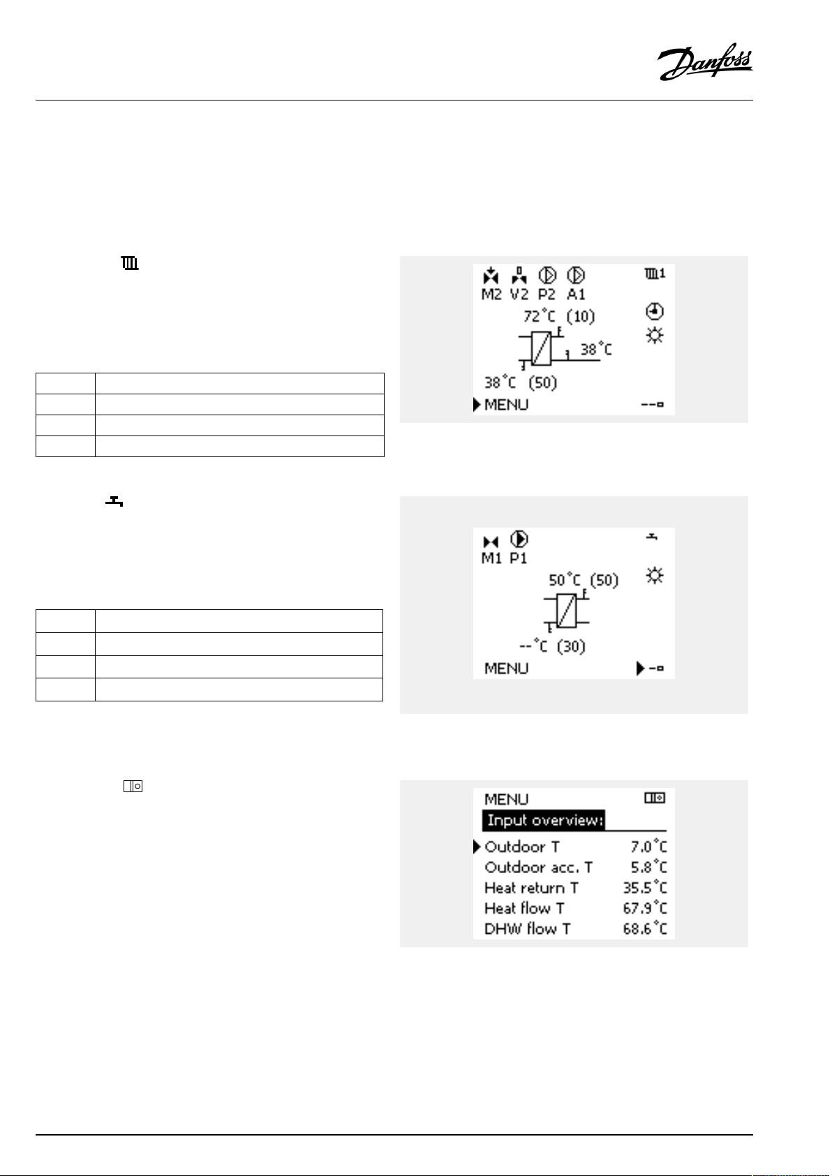
OperatingGuideECLComfort210/296/310,applicationA266
3.4Monitoringtemperaturesandsystemcomponents
ThissectiondescribesthefunctioningeneralfortheECLComfort
210/296/310series.Theshowndisplaysaretypicalandnot
applicationrelated.Theymightdifferfromthedisplaysinyour
application.
Heatingcircuit
Theoverviewdisplayintheheatingcircuitensuresaquick
overviewoftheactualand(desired)temperaturesaswellasthe
actualstateofthesystemcomponents.
Displayexample:
49°C
(31)
24°C
(50)
DHWcircuit
TheoverviewdisplayintheDHWcircuitensuresaquickoverview
oftheactualand(desired)temperaturesaswellastheactualstate
ofthesystemcomponents.
Displayexample(heatexchanger):
50°C
(50)
(30)
Flowtemperature
Desiredflowtemperature
Returntemperature
Returntemperaturelimitation
Flowtemperature
Desiredflowtemperature
--
Returntemperature:sensornotconnected
Returntemperaturelimitation
Displayexamplewithheatexchanger:
Inputoverview
Anotheroptiontogetaquickoverviewofmeasuredtemperatures
isthe'Inputoverview'whichisvisibleinthecommoncontroller
settings(howtoenterthecommoncontrollersettings,see
‘Introductiontocommoncontrollersettings’ .)
Asthisoverview(seedisplayexample)onlystatesthemeasured
actualtemperatures,itisread-only.
64|©Danfoss|2021.06
AQ156586461753en-010601
Page 65
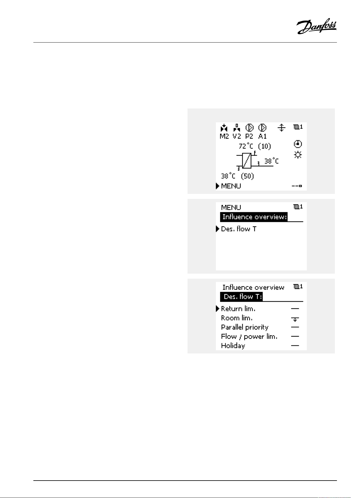
OperatingGuideECLComfort210/296/310,applicationA266
3.5Influenceoverview
ThissectiondescribesthefunctioningeneralfortheECLComfort
210/296/310series.Theshowndisplaysaretypicalandnot
applicationrelated.Theymightdifferfromthedisplaysinyour
application.
Themenugivesanoverviewoftheinfluencesonthedesired
flowtemperature.Itdiffersfromapplicationtoapplicationwhich
parametersarelisted.Itcanbehelpfulinaservicesituationto
explainunexpectedconditionsortemperaturesamongothers.
Ifthedesiredflowtemperatureisinfluenced(corrected)byoneor
moreparameters,itisindicatedbyasmalllinewitharrow-down,
arrow-upordouble-arrow:
Arrow-down:
Theparameterinquestionreducesthedesiredflowtemperature.
Arrow-up:
Theparameterinquestionincreasesthedesiredflowtemperature.
Double-arrow:
Theparameterinquestioncreatesanoverride(e.g.Holiday).
Straightline:
Noactiveinfluence.
Intheexample,thearrowinthesymbolpointsdownwardsfor
'Roomlim. ' .Thismeansthattheactualroomtemperatureis
higherthanthedesiredroomtemperaturewhichagainresultsina
decreaseofthedesiredflowtemperature.
ExampleofoverviewdisplaywithInfluenceindication:
AQ156586461753en-010601
©Danfoss|2021.06|65
Page 66
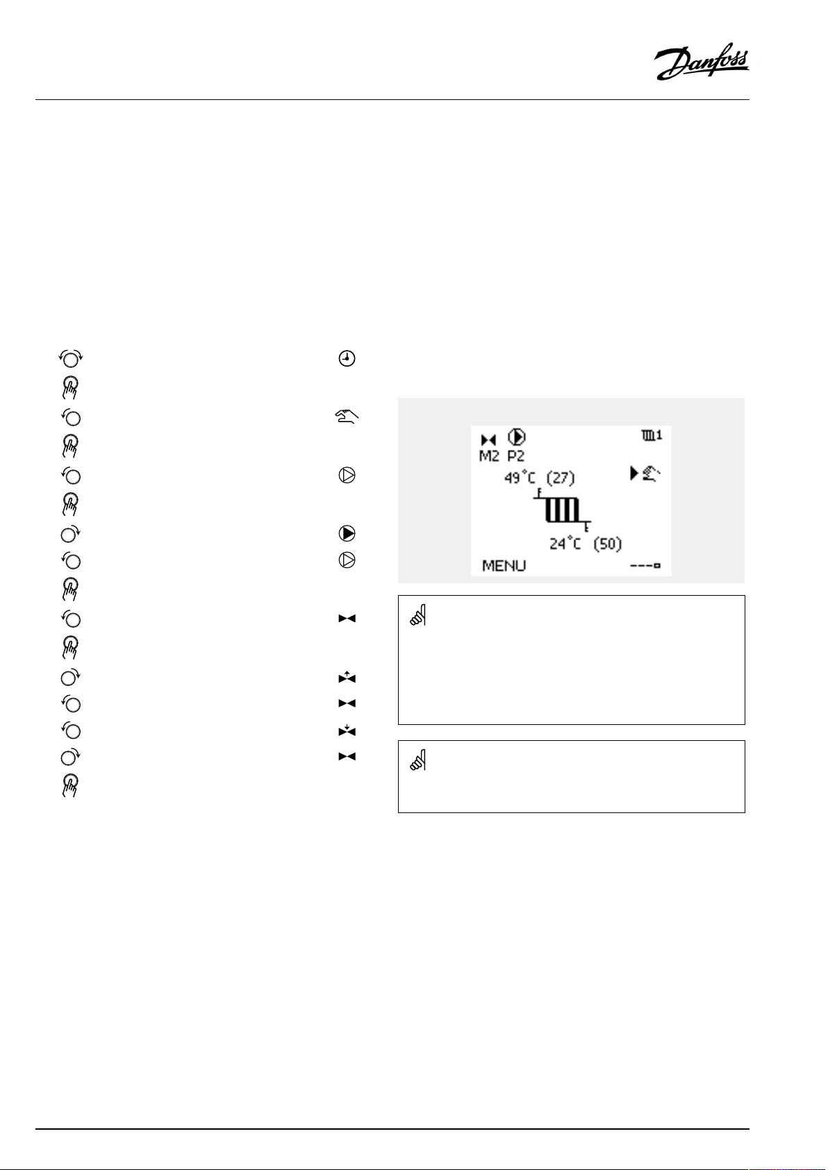
OperatingGuideECLComfort210/296/310,applicationA266
3.6Manualcontrol
ThissectiondescribesthefunctioningeneralfortheECLComfort
210/296/310series.Theshowndisplaysaretypicalandnot
applicationrelated.Theymightdifferfromthedisplaysinyour
application.
Itispossibletomanuallycontroltheinstalledcomponents.
Manualcontrolcanonlybeselectedinfavoritedisplaysinwhich
thesymbolsforthecontrolledcomponents(valve,pumpetc.)are
visible.
Action:Purpose:
Choosemodeselector
Confirm
Choosemanualmode
Confirm
Choosepump
Confirm
SwitchONthepump
SwitchOFFthepump.
Confirmpumpmode
Choosemotorizedcontrolvalve
Confirm
Openthevalve
Stopopeningthevalve
Closethevalve
Examples:
ControlledcomponentsCircuitselector
Duringmanualoperation:
•Allcontrolfunctionsaredeactivated
•Outputoverrideisnotpossible
•Frostprotectionisnotactive
Stopclosingthevalve
Confirmvalvemode
Toleavemanualcontrol,usethemodeselectortoselectthe
desiredmode.Pushthedial.
Manualcontrolistypicallyusedwhencommisioningthe
installation.Thecontrolledcomponents,valve,pumpetc.,canbe
controlledforcorrectfunction.
66|©Danfoss|2021.06
Whenmanualcontrolisselectedforonecircuit,itisautomatically
selectedforallcircuits!
AQ156586461753en-010601
Page 67
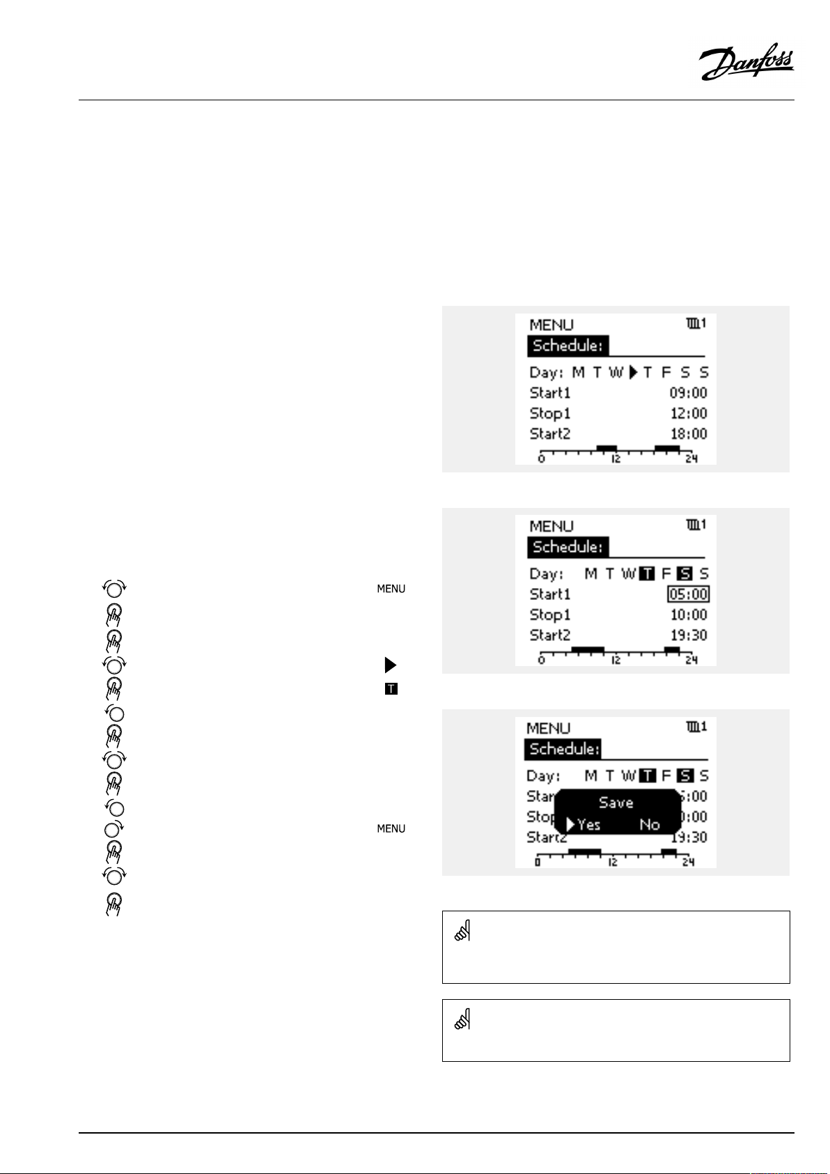
OperatingGuideECLComfort210/296/310,applicationA266
3.7Schedule
3.7.1Setyourschedule
ThissectiondescribesthescheduleingeneralfortheECLComfort
210/296/310series.Theshowndisplaysaretypicalandnot
applicationrelated.Theymightdifferfromthedisplaysinyour
application.Insomeapplications,however,theremightbemore
thanoneschedule.Additionalschedulescanbefoundin‘Common
controllersettings’ .
Thescheduleconsistsofa7-dayweek:
=
M
Monday
=
T
Tuesday
=
W
Wednesday
=
T
Thursday
=
F
Friday
=
S
Saturday
=
S
Sunday
Theschedulewillday-by-dayshowyouthestartandstoptimesof
yourcomfortperiods(heating/DHWcircuits).
Changingyourschedule:
Action:
Purpose:
Choose'MENU'inanyoftheoverview
displays
Confirm
Confirmthechoice'Schedule'
Choosethedaytochange
Confirm*
GotoStart1
Confirm
Adjustthetime
Confirm
GotoStop1,Start2etc.etc.
Returnto'MENU'
Confirm
Choose'Yes'or'No'in'Save'
Confirm
Examples:
*Severaldayscanbemarked
Thechosenstartandstoptimeswillbevalidforallthechosendays
(inthisexampleThursdayandSaturday).
Youcansetmax.3comfortperiodsaday.Youcandeleteacomfort
periodbysettingstartandstoptimestothesamevalue.
AQ156586461753en-010601
Eachcircuithasitsownschedule.Tochangetoanothercircuit,goto
'Home',turnthedialandchoosethedesiredcircuit.
Thestartandstoptimescanbesetinhalf-hourly(30min.)intervals.
©Danfoss|2021.06|67
Page 68
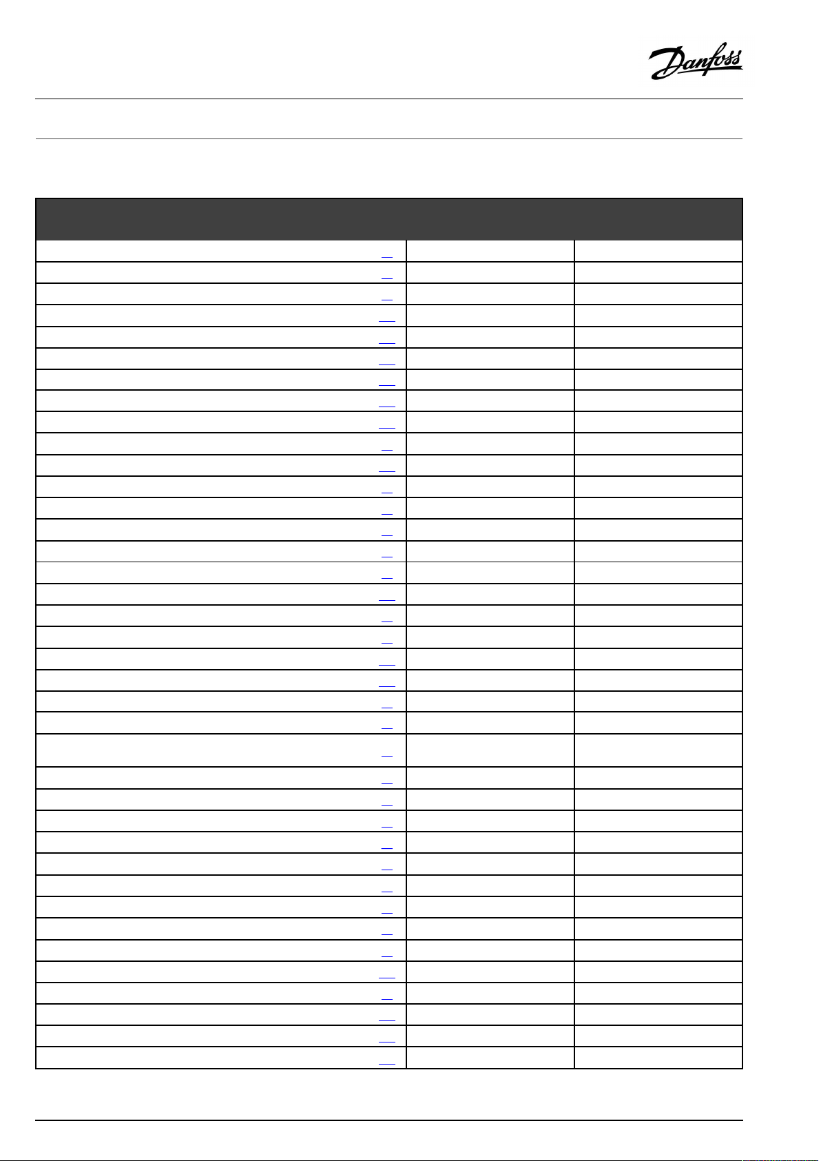
OperatingGuideECLComfort210/296/310,applicationA266
4.0Settingsoverview
Forfactorysettingsandsettingrange,seeappendix“ParameterIDoverview” .
ParametersindicatedwithanIDno.like"1x607"meanauniversalparameter.xstandsforcircuit/parametergroup.
SettingIDPage
Heatcurve
Actual(actualfloworpower)
Xpactual
Extendedheatcut-outsetting
Extendedwintercut-outsetting
Day
Starttime
Duration
DesiredT
DesiredT(Desiredflowtemperature)
ECAaddr.(ECAaddress,choiceofRemoteControlUnit)
Autosaving(savingtemp.dependentonoutdoortemp.)
Boost
Ramp(referenceramping)
Optimizer(optimizingtimeconstant)
Adapt.time(adaptiontime)
Demandoffset
Basedon(optimizationbasedonroom/outdoortemp.)
Totalstop
Pexercise(pumpexercise)
Mexercise(valveexercise)
Actuator
Pre-stop(optimizedstoptime)
Con.T,re.Tlim.(Constanttemperaturemode,return
temperaturelimitation)
DHW,ret.Tlimit
Limit(returntemp.limitation)
HighToutX1(returntemp.limitation,highlimit,X-axis)
LowlimitY1(returntemp.limitation,lowlimit,Y-axis)
LowToutX2(returntemp.limitation,lowlimit,X-axis)
HighlimitY2(returntemp.limitation,highlimit,Y-axis)
Infl.-max.(returntemp.limitation-max.influence)
Infl.-min.(returntemp.limitation-min.influence)
Adapt.time(adaptationtime)
Ppost-run
Paralleloperation
Pdemand
DHWpriority(closedvalve/normaloperation)
PfrostT(circulationpump,frostprotectiontemp.)
1x00473
1x010102
1x01188
1x01289
1x01390
1x01490
1x015
1x017102
1x02091
1x02191
1x022102
1x023103
1x02496
1x02692
1x02879
1x02979
1x03080
1x03180
1x03280
1x03380
1x03481
1x03581
1x03681
1x03781
1x040103
1x04392
1x050103
1x052104
1x077104
Factorysettingsincircuit(s)
1
72
84
98
111
111
120
120
121
121
75
2
68|©Danfoss|2021.06
AQ156586461753en-010601
Page 69
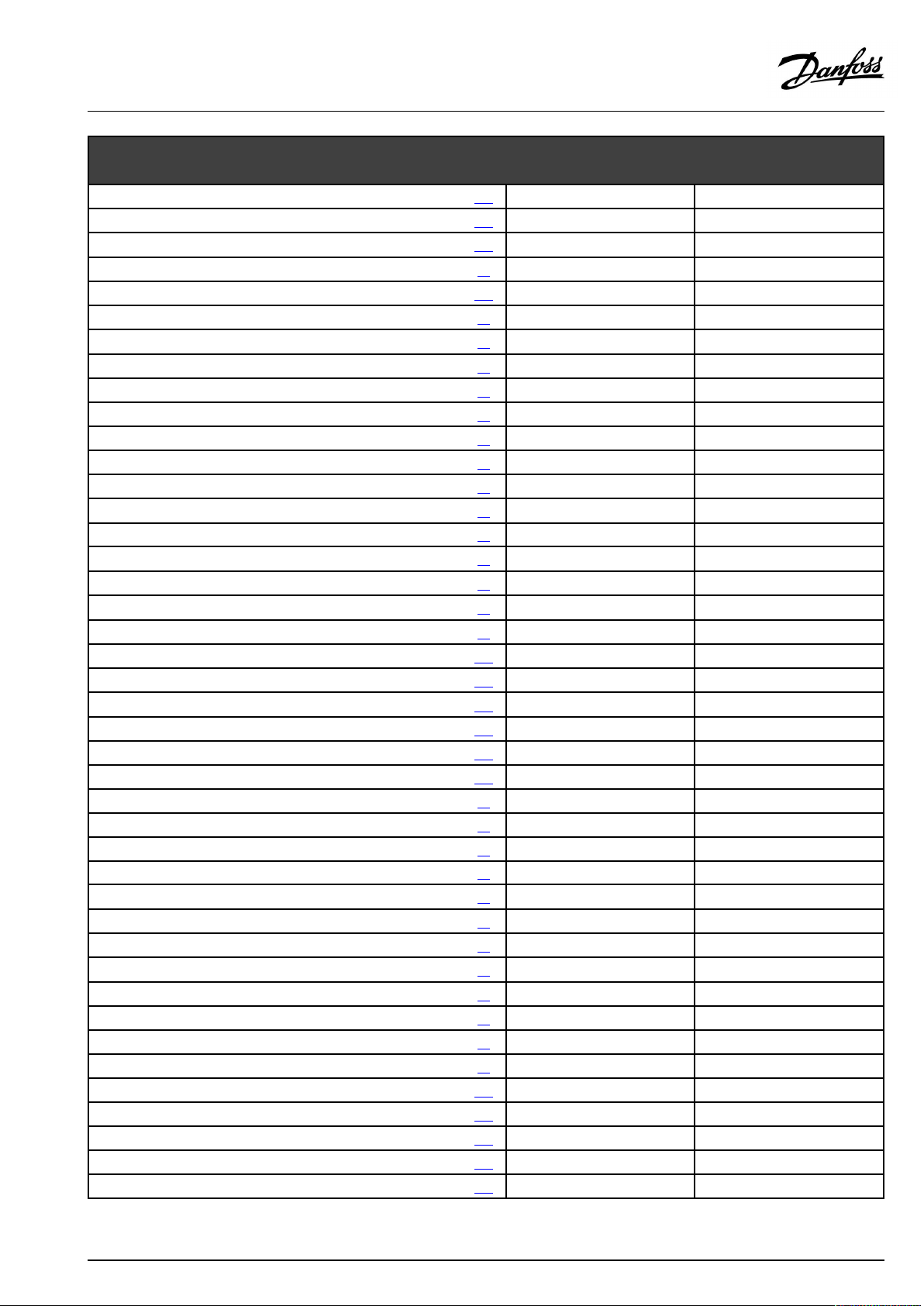
OperatingGuideECLComfort210/296/310,applicationA266
SettingIDPage
PheatT(heatdemand)
Max.flowT(Maximumflowtemperature)
Delay
Priority(priorityforreturntemp.limitation)
Frostpr.T(frostprotectiontemp.)
Opentime
Closetime
Tn(idle)
SupplyT(idle)
Inputtype
Limit(limitationvalue)
Adapt.time(adaptationtime)
Filterconstant
Pulse
Units
HighlimitY2(flow/powerlimitation,highlimit,Y-axis)
LowlimitY1(flow/powerlimitation,lowlimit,Y-axis)
LowToutX2(flow/powerlimitation,lowlimit,X-axis)
HighToutX1(flow/powerlimitation,highlimit,X-axis)
Ext.input(externaloverride)
Ext.mode(externaloverridemode)
Upperdifference
Lowerdifference
Delay,example
Lowesttemp.
Autotuning
Motorpr.(motorprotection)
Temp.min.
Temp.max.
Summer,cut-out(limitforheatingcut-out)
Infl.-max.(roomtemp.limitation,max.)
Infl.-min.(roomtemp.limitation,min.)
Xp(proportionalband)
Tn(integrationtimeconstant)
Mrun(runningtimeofthemotorizedcontrolvalve)
Nz(neutralzone)
Min.act.time(min.activationtimegearmotor)
SenddesiredT
LowX
HighX
LowY
HighY
1x078104
1x079
1x080
1x08582
1x093105
1x09496
1x09597
1x09697
1x09797
1x10984
1x111
1x11284
1x11385
1x114
1x115
1x11686
1x117
1x11886
1x11987
1x141
1x142106
1x147114
1x148
1x149
1x150116
1x17397
1x174
1x17774
1x178
1x17993
1x182
1x18376
1x18498
1x18599
1x18699
1x18799
1x18999
1x500108
1x607116
1x608116
1x609116
1x610
Factorysettingsincircuit(s)
1
114
114
84
85
85
86
105
115
115
98
74
75
117
2
AQ156586461753en-010601
©Danfoss|2021.06|69
Page 70

OperatingGuideECLComfort210/296/310,applicationA266
Alarmhigh
Alarmlow
Alarmtime-out
Alarmvalue
Alarmtime-out
SettingIDPage
1x614
1x615
1x617
1x636
1x637118
Factorysettingsincircuit(s)
1
117
117
117
117
2
70|©Danfoss|2021.06
AQ156586461753en-010601
Page 71

OperatingGuideECLComfort210/296/310,applicationA266
5.0Settings
5.1IntroductiontoSettings
Descriptionsofsettings(parameter'sfunctions)aredividedinto
groupsasusedintheECLComfort210/296/310controller's
menustructure.Examples:"Flowtemperature" ,"Roomlimit"and
soon.Eachgroupstartswithageneralexplanation.
Thedescriptionsofeachparameterareinnumericorder,relatedto
theparameter'sIDnumbers.Youmightcomeacrossdifferences
betweentheorderinthisOperatingGuideandtheECLComfort
210/296/310controllers.
Someparameterdescriptionsarerelatedtospecificapplication
subtypes.Thismeansthatyoumightnotseetherelatedparameter
intheactualsubtypeintheECLcontroller.
Thenote"SeeAppendix… "referstotheAppendixattheendof
thisOperatingGuide,whereparameter'ssettingrangesandfactory
settingsarelisted.
Thenavigationhints(forexampleMENU>Settings>Returnlimit
…)covermultiplesubtypes.
AQ156586461753en-010601
©Danfoss|2021.06|71
Page 72
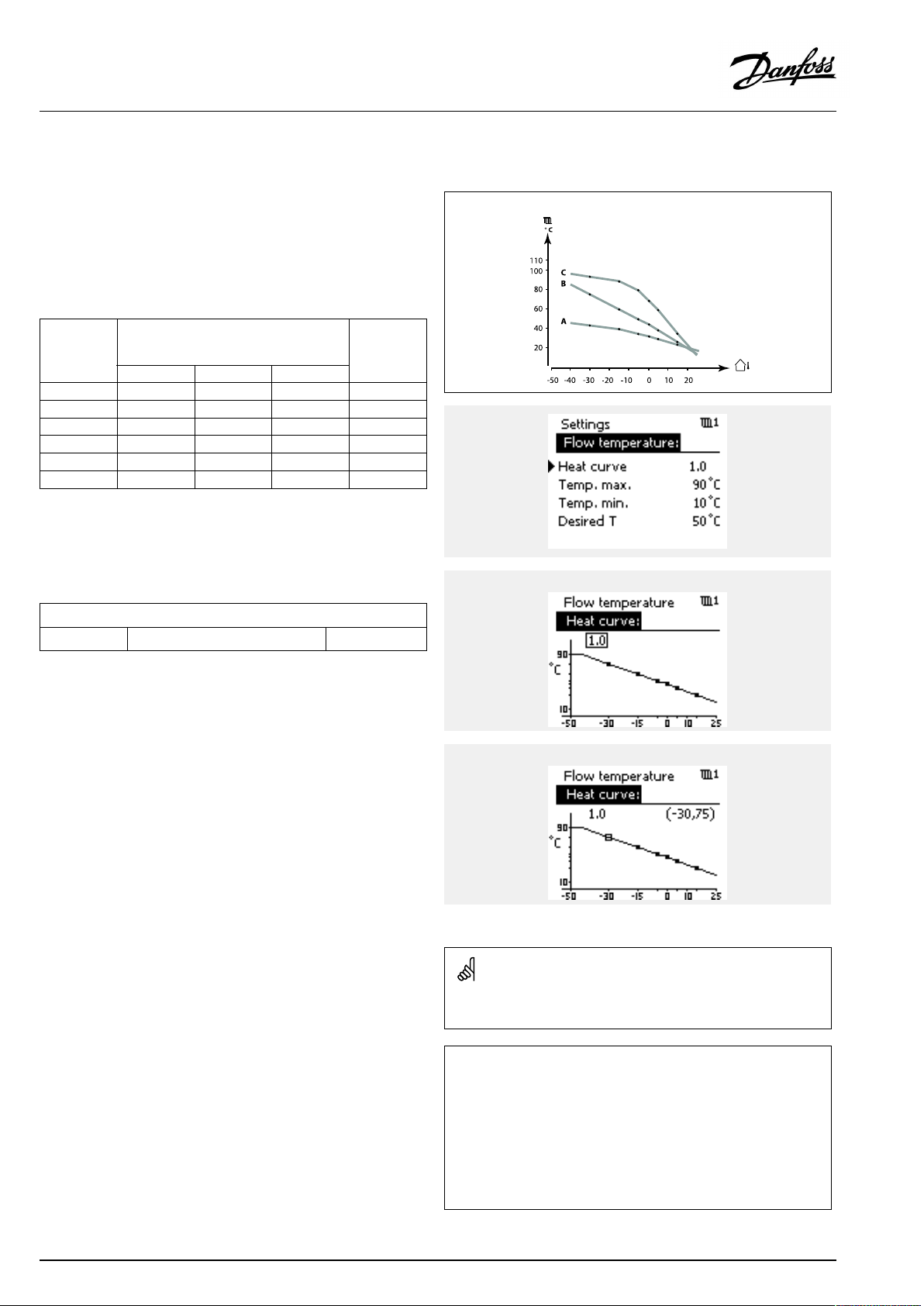
OperatingGuideECLComfort210/296/310,applicationA266
5.2Flowtemperature
TheECLComfortcontrollerdeterminesandcontrolstheflow
temperaturerelatedtotheoutdoortemperature.Thisrelationship
iscalledtheheatcurve.
Theheatcurveissetbymeansof6coordinatepoints.Thedesired
flowtemperatureissetat6pre-definedoutdoortemperature
values.
Theshownvaluefortheheatcurveisanaveragevalue(slope),
basedontheactualsettings.
Desiredflowtemperature
Outdoor
temp.
Desiredflowtemp.
A
BC
Your
settings
-30°C45°C75°C95°C
-15°C40°C60°C90°C
-5°C35°C50°C80°C
0°C32°C45°C70°C
5°C30°C40°C60°C
15°C25°C28°C35°C
A:Exampleforfloorheating
B:Factorysettings
C:Exampleforradiatorheating(highdemand)
MENU>Settings>Flowtemperature
Heatcurve
1
0.1...4.01.0
Theheatcurvecanbechangedintwoways:
1.Thevalueoftheslopeischanged(seeheatcurveexamples
onnextpage)
2.Thecoordinatesoftheheatcurvearechanged
Changethevalueoftheslope:
Pushthedialtoenter/changetheslopevalueoftheheatcurve
(example:1.0).
Whentheslopeoftheheatcurveischangedbymeansoftheslope
value,thecommonpointforallheatcurveswillbeadesiredflow
temperature=24.6°Catanoutdoortemperature=20°Canda
desiredroomtemperature=20.0°C.
Slopechanges
Coordinatechanges
Changethecoordinates:
Pushthedialtoenter/changethecoordinatesoftheheatcurve
(example:-30,75).
Theheatcurverepresentsthedesiredflowtemperaturesat
differentoutdoortemperaturesandatadesiredroomtemperature
of20°C.
Ifthedesiredroomtemperatureischanged,thedesiredflow
temperaturealsochanges:
(DesiredroomT-20)×HC×2.5
where"HC"istheHeatCurveslopeand"2.5"isaconstant.
72|©Danfoss|2021.06
Thecalculatedflowtemperaturecanbeinfluencedbythe‘Boost’and
‘Ramp’functionsetc.
Example:
Heatcurve:
Desiredflowtemp.:
Desiredroomtemp.:
Calculation(22–20)×1.0×2.5=
Result:
Thedesiredflowtemperaturewillbecorrectedfrom50°Cto55°C.
1.0
50°C
22°C
5
AQ156586461753en-010601
Page 73
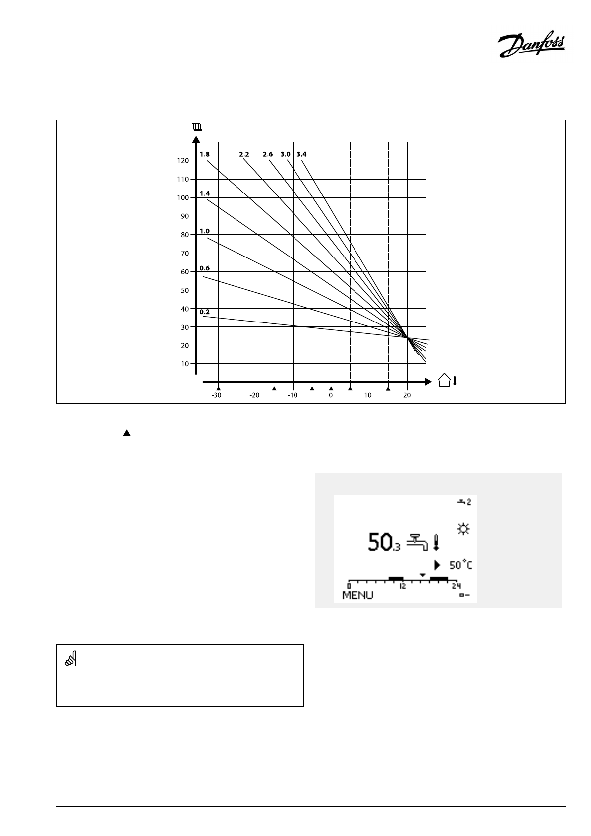
OperatingGuideECLComfort210/296/310,applicationA266
Choosingaheatcurveslope
Theheatcurvesrepresentthedesiredflowtemperatureatdifferentoutdoortemperaturesandatadesiredroomtemperatureof20°C.
Thesmallarrows()indicate6differentoutdoortemperaturevaluesatwhichyoucanchangetheheatcurve.
TheECLComfort210/296/310controlstheDHWtemperature
accordingtothedesiredflowtemperatureforexampleunderthe
influenceofthereturntemperature.
ActualDHWtemp.
ThedesiredDHWtemperatureissetintheoverviewdisplay.
50.3:
50:
ActualDHWtemperature
DesiredDHWtemperature
ParametersindicatedwithanIDno.like"1x607"meanauniversal
parameter.
xstandsforcircuit/parametergroup.
DesiredDHW
temp.
AQ156586461753en-010601
©Danfoss|2021.06|73
Page 74

OperatingGuideECLComfort210/296/310,applicationA266
MENU>Settings>Flowtemperature
DesiredT(Desiredflowtemperature)
WhentheECLComfortisinoverridemode,type"Const.T",thedesiredflow
temperaturecanbeset.
A"Const.T"relatedreturntemperaturelimitationcanalsobeset.SeeMENU
>Settings>Returnlimit>'Con.T,ret.Tlim. '
1x004
SeeAppendix“ParameterIDoverview”
MENU>Settings>Flowtemperature
Temp.min.
1x177
SeeAppendix“ParameterIDoverview”
Setthemin.flowtemperatureforthesystem.Thedesiredflow
temperaturewillnotbelowerthanthissetting.Adjustthefactory
setting,ifrequired.
Overridemode
WhenECLComfortisinScheduledmode,acontact(switch)signalcan
beappliedtoaninputinordertooverridetoComfort,Saving,Frost
ProtectionorConstanttemperature.Aslongasthecontact(switch)
signalisapplied,theoverrideisactive.
The"DesiredT"valuecanbeinfluencedby:
•temp.max.
•temp.min.
•roomtemp.limit
•returntemp.limit
•flow/powerlimit
‘Temp.min.’isoverruledif'Totalstop'isactiveinSavingmodeor
'Cut-out'isactive.
‘Temp.min.’canbeoverruledbytheinfluencefromthereturn
temperaturelimitation(see'Priority').
MENU>Settings>Flowtemperature
Temp.max.
1x178
SeeAppendix“ParameterIDoverview”
Setthemax.flowtemperatureforthesystem.Thedesired
temperaturewillnotbehigherthanthissetting.Adjustthefactory
setting,ifrequired.
Thesettingfor‘Temp.max. ’hashigherprioritythan‘Temp.min.’ .
Thesettingof‘heatcurve’ispossibleforheatingcircuitsonly.
Thesettingfor‘Temp.max. ’hashigherprioritythan‘Temp.min.’ .
74|©Danfoss|2021.06
AQ156586461753en-010601
Page 75

OperatingGuideECLComfort210/296/310,applicationA266
5.3Roomlimit
ThefollowingsectionisageneraldescriptionforRoom
temperaturelimitation.
Theactualapplicationmightnothavebothlimitationtypes.
Thissectionisonlyrelevantifyouhaveinstalledaroom
temperaturesensororaRemoteControlUnitforutilizingtheroom
temperaturesignal.
Inthefollowingdescriptionisreferredto"flowtemperature"in
general.
Thecontrolleradjuststhedesiredflowtemperaturetocompensate
forthedifferencebetweenthedesiredandtheactualroom
temperature.
Iftheroomtemperatureishigherthanthedesiredvalue,the
desiredflowtemperaturecanbereduced.
The'Infl.-max.'(Influence,max.roomtemp.)determineshow
muchthedesiredflowtemperatureshouldbereduced.
Usethisinfluencetypetoavoidatoohighroomtemperature.The
controllerwillallowforfreeheatgains,i.e.solarradiationorheat
fromafireplaceetc.
Iftheroomtemperatureislowerthanthedesiredvalue,thedesired
flowtemperaturecanbeincreased.
The'Infl.-min.'(Influence,min.roomtemperature)determines
howmuchthedesiredflowtemperatureshouldbeincreased.
Usethisinfluencetypetoavoidatoolowroomtemperature.This
coulde.g.becausedbywindysurroundings.
Atypicalsettingwillbe-4.0for'Infl.-max.'and4.0for'Infl.-min. '
ParametersindicatedwithanIDno.like"1x607"meanauniversal
parameter.
xstandsforcircuit/parametergroup.
MENU>Settings>Roomlimit
Adapt.time(adaptiontime)
Controlshowfasttheactualroomtemperatureadaptstothedesiredroom
temperature(Icontrol).
1x015
Theadaptationfunctioncancorrectthedesiredroomtemperature
withmax.8Kxheatcurveslopevalue.
SeeAppendix“ParameterIDoverview”
OFF:
Thecontrolfunctionisnotinfluencedbythe'Adapt.
time'.
Minor
Thedesiredroomtemperatureisadaptedquickly.
value:
Major
Thedesiredroomtemperatureisadaptedslowly.
value:
AQ156586461753en-010601
©Danfoss|2021.06|75
Page 76

OperatingGuideECLComfort210/296/310,applicationA266
MENU>Settings>Roomlimit
Infl.-max.(roomtemp.limitation,max.)
Determineshowmuchthedesiredflowtemperaturewillbeinfluenced
(decreased)iftheactualroomtemperatureishigherthanthedesiredroom
temperature(Pcontrol).
SeeAppendix“ParameterIDoverview”
0.0:
-2.0:
-5.0:
-9.9:
Noinfluence
Minorinfluence
Mediuminfluence
Maximuminfluence
1x182
=
X
#1#
#2#
#3#
Roomtemperature
=
Desiredroomtemperature
=
Negativeinfluence(1x082)whenactualroomtemp.getshigher
thandesiredroomtemp.
=
Positiveinfluence(1x083)whenactualroomtemp.getslowerthan
desiredroomtemp.
The‘Infl.-max.’and'Infl.-min. 'determinehowmuchtheroom
temperatureshouldinfluencethedesiredflowtemperature.
Ifthe‘Infl. ’factoristoohighand/orthe‘ Adapt.time’toolow,thereis
ariskofunstablecontrol.
Example
Theactualroomtemperatureis2degreestoohigh.
The‘Infl.-max.’issetto-4.0.
Theheatcurveslopeis1.8(see'Heatcurve'in'Flowtemperature').
Result:
Thedesiredflowtemperatureischangedby(2x-4.0x1.8)
–14.4degrees.
MENU>Settings>Roomlimit
Infl.-min.(roomtemp.limitation,min.)
Determineshowmuchthedesiredflowtemperaturewillbeinfluenced
(increased)iftheactualroomtemperatureislowerthanthedesiredroom
temperature(Pcontrol).
SeeAppendix“ParameterIDoverview”
9.9:
5.0:
2.0:
0.0:
Maximuminfluence
Mediuminfluence
Minorinfluence
Noinfluence
Inapplicationsubtypes,whereaheatcurveslopevalueisnotpresent,
theheatcurveslopevalueissetto1:
Result:
Thedesiredflowtemperatureischangedby(2x-4.0x1):
–8.0degrees.
Example
1x183
Theactualroomtemperatureis2degreestoolow.
The‘Infl.-min.’issetto4.0.
Theheatcurveslopeis1.8(see'Heatcurve'in'Flowtemperature').
Result:
Thedesiredflowtemperatureischangedby(2x4.0x1.8)
14.4degrees.
Inapplicationsubtypes,whereaheatcurveslopevalueisnotpresent,
theheatcurveslopevalueissetto1:
Result:
Thedesiredflowtemperatureischangedby(2x4.0x1):
8.0degrees.
76|©Danfoss|2021.06
AQ156586461753en-010601
Page 77

OperatingGuideECLComfort210/296/310,applicationA266
5.4Returnlimit
Thereturntemperaturelimitationisbasedontheoutdoor
temperature.Typicallyindistrictheatingsystemsahigherreturn
temperatureisacceptedatadecreaseinoutdoortemperature.The
relationshipbetweenthereturntemperaturelimitsandoutdoor
temperatureissetintwocoordinates.
Theoutdoortemperaturecoordinatesaresetin'HighToutX1'
and'LowToutX2' .Thereturntemperaturecoordinatesaresetin
'HighlimitY2'and'LowlimitY1' .
Thecontrollerautomaticallychangesthedesiredflowtemperature
toobtainanacceptablereturntemperaturewhenthereturn
temperaturefallsbeloworgetshigherthanthecalculatedlimit.
ThislimitationisbasedonaPIregulationwhereP('Infl.'factor)
respondsquicklytodeviationsandI('Adapt.time')responds
slowerandovertimeremovesthesmalloffsetsbetweenthe
desiredandactualvalues.Thisisdonebychangingthedesired
flowtemperature.
X
Y
#X1#
#X2#
#Y1#
#Y2#
=
Outdoortemperature
=
Limitationtemperature
=
HighTout(1x031)
=
LowTout(1x033)
=
Lowlimit(1x032)
=
Highlimit(1x034)
DHWcircuit
Thereturntemperaturelimitationisbasedonaconstant
temperaturevalue.
Thecontrollerautomaticallychangesthedesiredflowtemperature
toobtainanacceptablereturntemperaturewhenthereturn
temperaturefallsbeloworgetshigherthanthesetlimit.
ThislimitationisbasedonaPIregulationwhereP('Infl.'factor)
respondsquicklytodeviationsandI('Adapt.time')responds
slowerandovertimeremovesthesmalloffsetsbetweenthe
desiredandactualvalues.Thisisdonebychangingthedesired
flowtemperature.
Thecalculatedlimitisshowninbrackets()inthemonitoringdisplay.
Seethesection"Monitoringtemperaturesandsystemcomponents" .
=
X
#1#
#2#
#3#
#4#
#5#
Returntemperature
=
Limitationtemperature
Negativeinfluence(1x035)whenreturntemp.getshigherthan
=
limit.temp.
Negativeinfluence(1x036)whenreturntemp.getslowerthan
=
limit.temp.
Positiveinfluence(1x036)whenreturntemp.getslowerthanlimit.
=
temp.
Positiveinfluence(1x035)whenreturntemp.getshigherthan
=
limit.temp.
Ifthe‘Infl. ’factoristoohighand/orthe‘ Adapt.time’toolow,thereis
ariskofunstablecontrol.
AQ156586461753en-010601
©Danfoss|2021.06|77
Page 78

OperatingGuideECLComfort210/296/310,applicationA266
Example,maximumreturntemperaturelimitation;
returntemperaturegetshigherthanlimit
T
Y
X
#1#
#2#
#3#
#4#
=
Temperature
=
Temperature
=
Time
=
Returntemperature
=
Returntemperaturelimit
=
Desiredflowtemperature
=
Actionpoint
78|©Danfoss|2021.06
AQ156586461753en-010601
Page 79

OperatingGuideECLComfort210/296/310,applicationA266
Example,minimumreturntemperaturelimitation;
returntemperaturegetslowerthanlimit
T
Y
X
#1#
#2#
#3#
#4#
=
Temperature
=
Temperature
=
Time
=
Returntemperature
=
Returntemperaturelimit
=
Desiredflowtemperature
=
Actionpoint
ParametersindicatedwithanIDno.like"1x607"meanauniversal
parameter.
xstandsforcircuit/parametergroup.
MENU>Settings>Returnlimit
Con.T,re.Tlim.(Constanttemperaturemode,return
temperaturelimitation)
The"Con.T ,ret.Tlimit"isthereturntemperaturelimitationvaluewhenthe
circuitissettooverridemodetype"Const.T"(=Constanttemperature).
SeeAppendix“ParameterIDoverview”
Value:Setthereturntemperaturelimitation
1x028
Overridemode
WhenECLComfortisinScheduledmode,acontact(switch)signalcan
beappliedtoaninputinordertooverridetoComfort,Saving,Frost
ProtectionorConstanttemperature.Aslongasthecontact(switch)
signalisapplied,theoverrideisactive.
AQ156586461753en-010601
©Danfoss|2021.06|79
Page 80
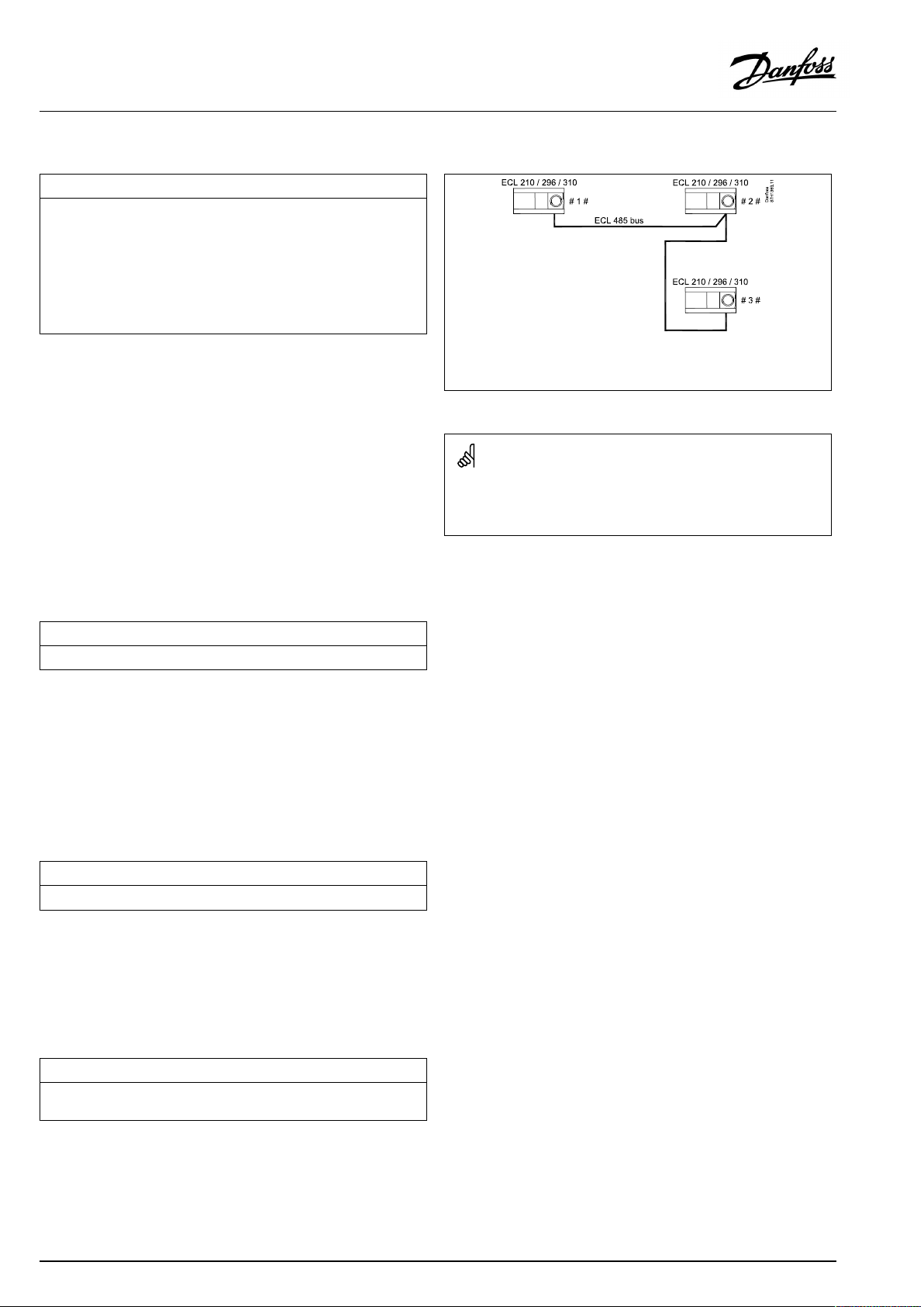
OperatingGuideECLComfort210/296/310,applicationA266
MENU>Settings>Returnlimit
DHW,ret.Tlimit
WhenanaddressedslaveisactiveinDHW-tankheating/charging,the
returntemperaturelimitationinthemastercanbeset.
Notes:
•Themastercircuitmustbesettoreactonthedesiredflowtemperature
intheslave(s).See"Demandoffset"(ID11017).
•Theslave(s)mustbesettosendits/theirdesiredflowtemperatureto
themaster.See"SenddesiredT"(ID1x500).
SeeAppendix“ParameterIDoverview”
OFF:
Noinfluencefromslaves.Thereturntemperature
limitationisrelatedtosettingsin"Returnlimit" .
Value:Returntemperaturelimitationvaluewhenslaveisin
DHWtankheating/chargingoperation.
MENU>Settings>Returnlimit
Limit(returntemp.limitation)
Setthereturntemperaturevalueyouacceptforthesystem.
1x029
#1#=Master,exampleA266,address15
#2#=Slave,exampleA237,address9
#3#=Slave,exampleA367,address6
SomeexamplesofapplicationswithDHW-tankheating/chargingare:
•A217,A237,A247,A367,A377
1x030
SeeAppendix“ParameterIDoverview”
Whenthereturntemperaturefallsbeloworgetshigherthanthe
setvalue,thecontrollerautomaticallychangesthedesiredflow/
ducttemperaturetoobtainanacceptablereturntemperature.The
influenceissetin'Infl.-max. 'and'Infl.-min.' .
MENU>Settings>Returnlimit
HighToutX1(returntemp.limitation,highlimit,X-axis)
Settheoutdoortemperaturevalueforthelowreturntemperaturelimitation.
1x031
SeeAppendix“ParameterIDoverview”
ThecorrespondingYcoordinateissetin'LowlimitY1' .
MENU>Settings>Returnlimit
LowlimitY1(returntemp.limitation,lowlimit,Y-axis)
Setthereturntemperaturelimitationreferringtotheoutdoortemperature
valuesetin'HighToutX1' .
1x032
SeeAppendix“ParameterIDoverview”
ThecorrespondingXcoordinateissetin'HighToutX1' .
80|©Danfoss|2021.06
AQ156586461753en-010601
Page 81

OperatingGuideECLComfort210/296/310,applicationA266
MENU>Settings>Returnlimit
LowToutX2(returntemp.limitation,lowlimit,X-axis)
Settheoutdoortemperaturevalueforthehighreturntemperature
limitation.
SeeAppendix“ParameterIDoverview”
ThecorrespondingYcoordinateissetin'HighlimitY2'.
MENU>Settings>Returnlimit
HighlimitY2(returntemp.limitation,highlimit,Y-axis)
Setthereturntemperaturelimitationreferringtotheoutdoortemperature
valuesetin'LowToutX2' .
SeeAppendix“ParameterIDoverview”
ThecorrespondingXcoordinateissetin'LowToutX2' .
MENU>Settings>Returnlimit
Infl.-max.(returntemp.limitation-max.influence)
Determineshowmuchthedesiredflowtemperaturewillbeinfluencedifthe
returntemperatureishigherthanthesetlimit.
SeeAppendix“ParameterIDoverview”
1x033
1x034
Example
1x035
Thereturnlimitisactiveabove50°C.
Theinfluenceissetto0.5.
Theactualreturntemperatureis2degreestoohigh.
Result:
Thedesiredflowtemperatureischangedby0.5x2=1.0degree.
Influencehigherthan0:
Thedesiredflowtemperatureisincreased,whenthereturn
temperaturegetshigherthanthesetlimit.
Influencelowerthan0:
Thedesiredflowtemperatureisdecreased,whenthereturn
temperaturegetshigherthanthesetlimit.
MENU>Settings>Returnlimit
Infl.-min.(returntemp.limitation-min.influence)
Determineshowmuchthedesiredflowtemperaturewillbeinfluencedifthe
returntemperatureislowerthanthecalculatedlimit.
SeeAppendix“ParameterIDoverview”
Influencehigherthan0:
Thedesiredflowtemperatureisincreased,whenthereturn
temperaturegetsbelowthecalculatedlimit.
Influencelowerthan0:
Thedesiredflowtemperatureisdecreased,whenthereturn
temperaturegetsbelowthecalculatedlimit.
Example
1x036
Thereturnlimitisactivebelow50°C.
Theinfluenceissetto-3.0.
Theactualreturntemperatureis2degreestoolow.
Result:
Thedesiredflowtemperatureischangedby-3.0x2=-6.0degrees.
Normally,thissettingis0indistrictheatingsystemsbecausealower
returntemperatureisacceptable.
Typically,thissettingishigherthan0inboilersystemstoavoidatoo
lowreturntemperature(seealso'Infl.-max.').
AQ156586461753en-010601
©Danfoss|2021.06|81
Page 82
OperatingGuideECLComfort210/296/310,applicationA266
MENU>Settings>Returnlimit
Adapt.time(adaptationtime)
Controlshowfastthereturntemperatureadaptstothedesiredreturn
temperaturelimit(Integrationcontrol).
SeeAppendix“ParameterIDoverview”
OFF:
Thecontrolfunctionisnotinfluencedbythe‘Adapt.
time’ .
Minor
Thedesiredtemperatureisadaptedquickly.
value:
Major
Thedesiredtemperatureisadaptedslowly.
value:
MENU>Settings>Returnlimit
Priority(priorityforreturntemp.limitation)
Choosewhetherthereturntemperaturelimitationshouldoverruletheset
min.flowtemperature‘Temp.min. ’.
SeeAppendix“ParameterIDoverview”
OFF:
ON:
Themin.flowtemperaturelimitisnotoverruled.
Themin.flowtemperaturelimitisoverruled.
1x037
Theadaptationfunctioncancorrectthedesiredflowtemperature
withmax.8K.
1x085
IfyouhaveaDHWapplication:
Pleasealsosee‘Paralleloperation’(ID11043).
IfyouhaveaDHWapplication:
Whendependentparalleloperationisinfunction:
•Desiredflowtemperaturefortheheatingcircuitwillbeminimum
limited,when"Priorityforreturntemperature"(ID1x085)isset
toOFF.
•Desiredflowtemperaturefortheheatingcircuitwillnotbe
minimumlimited,when"Priorityforreturntemperature"
(ID1x085)issettoON.
82|©Danfoss|2021.06
AQ156586461753en-010601
Page 83
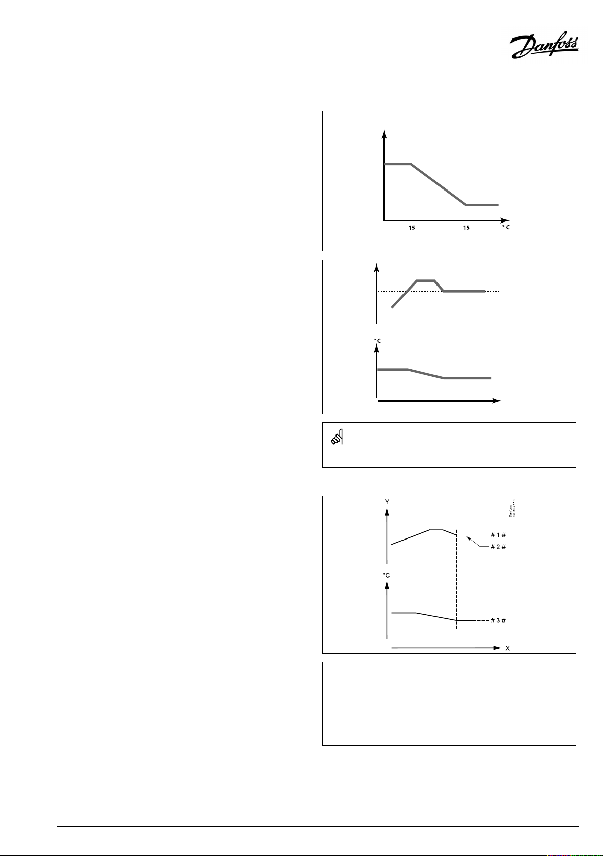
OperatingGuideECLComfort210/296/310,applicationA266
5.5Flow/powerlimit
Afloworenergymetercanbeconnected(M-bussignal)totheECL
controllerinordertolimitthefloworconsumedpower.
Theflow/powerlimitationcanbebasedontheoutdoor
temperature.Typically,indistrictheatingsystemsahigherflowor
powerisacceptedatloweroutdoortemperatures.
Therelationshipbetweenthefloworpowerlimitsandtheoutdoor
temperatureissetintwocoordinates.
Theoutdoortemperaturecoordinatesaresetin'HighToutX1'
and'LowToutX2'.
Thefloworpowercoordinatesaresetin'LowlimitY1'and'High
limitY2' .Basedonthesesettings,thecontrollercalculatesthe
limitationvalue.
Whentheflow/powergetshigherthanthecalculatedlimit,the
controllergraduallyreducesthedesiredflowtemperaturetoobtain
anacceptablemax.floworpowerconsumption.
HighlimitY2
LowlimitY1
Flow/power
limitation
Desiredflow
temp.
Flow/powerlimitation
LowToutX2
Outdoortemp.
HighToutX1
Limit
Time
DHWcircuit
AfloworheatmetercanbeconnectedtotheECLcontrollerin
ordertolimitthefloworconsumedpower.Thesignalfromthe
floworheatmeterisapulsesignal.
WhentheapplicationrunsinanECLComfort296/310controller,
theflow/powersignalcanbeobtainedfromaflow/heatmeter
viatheM-busconnection.
Whentheflow/powergetshigherthanthecalculatedlimit,the
controllergraduallyreducesthedesiredflowtemperaturetoobtain
anacceptablemax.floworpowerconsumption.
Ifthe‘Adapt.time’istoohigh,thereisariskofunstablecontrol.
=
X
Y
#1#
#2#
#3#
Time
=
Floworpower
=
Floworpowerlimit
=
Actualfloworenergy
=
Desiredflowtemperature
Theparameter'Units'(ID1x115)hasareducedsettingrangewhen
theflow/energysignalcomesviaM-bus.
AQ156586461753en-010601
©Danfoss|2021.06|83
Page 84
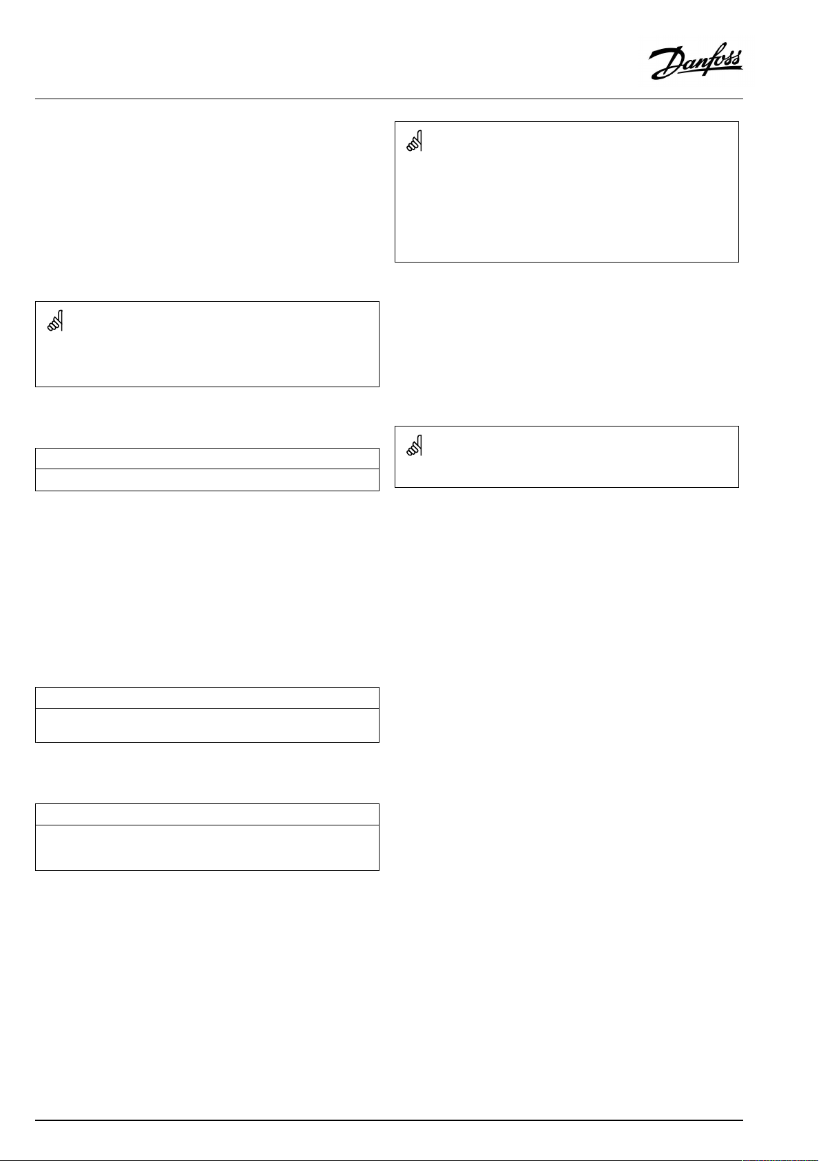
OperatingGuideECLComfort210/296/310,applicationA266
ParametersindicatedwithanIDno.like"1x607"meanauniversal
parameter.
xstandsforcircuit/parametergroup.
MENU>Settings>Flow/powerlimit
Pulsebasedsignalforflow/power ,appliedtoinputS7
Formonitoring:
Frequencyrangeis0.01-200Hz
Forlimitation:
Minimumfrequencyisrecommendedtobe1Hzinordertohavea
stablecontrol.Furthermore,thepulsesmustappearregularly.
Inputtype
Choiceofinputtypefromflow/energymeter
SeeAppendix“ParameterIDoverview”
OFF:
IM1-
Noinput
Flow/energymetersignalbasedonpulses.
IM5:
EM1-
Flow/energymetersignalfromM-bus.
EM5:
MENU>Settings>Flow/powerlimit
Actual(actualfloworpower)
Thevalueistheactualfloworpowerbasedonthesignalfromflow/energy
meter.
MENU>Settings>Flow/powerlimit
Limit(limitationvalue)
Thisvalueisinsomeapplicationsacalculatedlimitationvalue,basedonthe
actualoutdoortemperature.
Inotherapplicationsthevalueisaselectablelimitationvalue.
1x10⁹
ThesettingrangeforIMandEMdependsonchosensubtype.
1x111
SeeAppendix“ParameterIDoverview”
84|©Danfoss|2021.06
AQ156586461753en-010601
Page 85
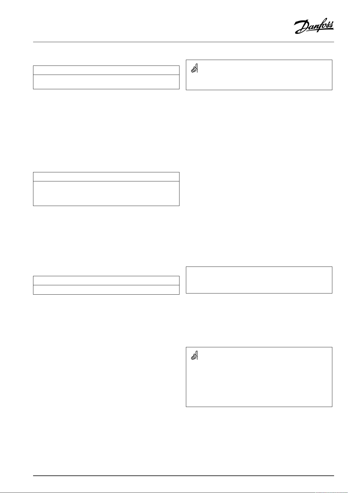
OperatingGuideECLComfort210/296/310,applicationA266
MENU>Settings>Flow/powerlimit
Adapt.time(adaptationtime)
Controlshowfasttheflow/powerlimitationadaptstothedesired
limitation.
SeeAppendix“ParameterIDoverview”
OFF:
Thecontrolfunctionisnotinfluencedbythe‘Adapt.
time’ .
Minor
Thedesiredtemperatureisadaptedquickly.
value:
Major
Thedesiredtemperatureisadaptedslowly.
value:
MENU>Settings>Flow/powerlimit
Filterconstant
Thevalueofthefilterconstantdeterminesthedampeningofthemeasured
value.
Thehigherthevalue,themoredampening.
Bythis,atooquickchangeofthemeasuredvaluecanbeavoided.
SeeAppendix“ParameterIDoverview”
Minor
Lowerdampening
value:
Major
Higherdampening
value:
1x112
Ifthe‘Adapt.time’istoolow,thereisariskofunstablecontrol.
1x113
MENU>Settings>Flow/powerlimit
Pulse
Setthevalueofthepulsesfromtheflow/energymeter.
SeeAppendix“ParameterIDoverview”
OFF:
1...9999:
Noinput.
Pulsevalue.
Example:
1x114
Onepulsecanrepresentanumberoflitres(fromaflowmeter)
oranumberofkWh(fromaenergymeter).
Pulsebasedsignalforflow/power ,appliedtoinputS7
Formonitoring:
Frequencyrangeis0.01-200Hz
Forlimitation:
Minimumfrequencyisrecommendedtobe1Hzinordertohavea
stablecontrol.Furthermore,thepulsesmustappearregularly.
AQ156586461753en-010601
©Danfoss|2021.06|85
Page 86
OperatingGuideECLComfort210/296/310,applicationA266
MENU>Settings>Flow/powerlimit
Units
Choiceofunitsformeasuredvalues.
SeeAppendix“ParameterIDoverview”
Unitstotheleft:pulsevalue.
Unitstotheright:actualandlimitationvalues.
Thevaluefromtheflowmeterisexpressedasmlorl.
ThevaluefromtheenergymeterisexpressedasWh,kWh,MWh
orGWh.
Thevaluesfortheactualflowandtheflowlimitationareexpressed
asl/horm³/h.
Thevaluesfortheactualpowerandthepowerlimitationare
expressedaskW,MWorGW.
1x115
Listforsettingrangeof'Units':
ml,l/h
l,l/h
ml,m³/h
l,m³/h
Wh,kW
kWh,kW
kWh,MW
MWh,MW
MWh,GW
GWh,GW
Example1:
'Units'(11115):
'Pulse'(11114):
l,m³/h
10
Eachpulserepresents10litresandtheflowisexpressedascubic
meters(m³)perhour.
Example2:
'Units'(11115):
'Pulse'(11114):
kWh,kW(=kiloWatthour,kiloWatt)
1
Eachpulserepresents1kiloWatthourandthepoweris
expressedinkiloWatt.
MENU>Settings>Flow/powerlimit
HighlimitY2(flow/powerlimitation,highlimit,Y-axis)
Settheflow/powerlimitationreferringtotheoutdoortemperatureset
in'LowToutX2' .
SeeAppendix“ParameterIDoverview”
ThecorrespondingXcoordinateissetin'LowToutX2' .
MENU>Settings>Flow/powerlimit
LowlimitY1(flow/powerlimitation,lowlimit,Y-axis)
Settheflow/powerlimitationreferringtotheoutdoortemperaturesetin
'HighToutX1' .
SeeAppendix“ParameterIDoverview”
ThecorrespondingXcoordinateissetin'HighToutX1' .
1x116
1x117
Thelimitationfunctioncanoverruletheset'Temp.min'ofthedesired
flowtemperature.
86|©Danfoss|2021.06
AQ156586461753en-010601
Page 87

OperatingGuideECLComfort210/296/310,applicationA266
MENU>Settings>Flow/powerlimit
LowToutX2(flow/powerlimitation,lowlimit,X-axis)
Settheoutdoortemperaturevalueforthehighflow/powerlimitation.
SeeAppendix“ParameterIDoverview”
ThecorrespondingYcoordinateissetin'HighlimitY2'.
MENU>Settings>Flow/powerlimit
HighToutX1(flow/powerlimitation,highlimit,X-axis)
Settheoutdoortemperaturevalueforthelowflow/powerlimitation.
SeeAppendix“ParameterIDoverview”
ThecorrespondingYcoordinateissetin'LowlimitY1' .
1x118
1x119
AQ156586461753en-010601
©Danfoss|2021.06|87
Page 88

OperatingGuideECLComfort210/296/310,applicationA266
5.6Optimization
Thesection"Optimization"describesspecificapplicationrelated
issues.
Theparameters'Autosaving' ,'Boost','Optimizer','Totalstop'areall
relatedtoheatingmodeonly.
'Summer,cut-out'determine,atrisingoutdoortemperature,the
stopofheating.
ParametersindicatedwithanIDno.like"1x607"meanauniversal
parameter.
xstandsforcircuit/parametergroup.
88|©Danfoss|2021.06
AQ156586461753en-010601
Page 89
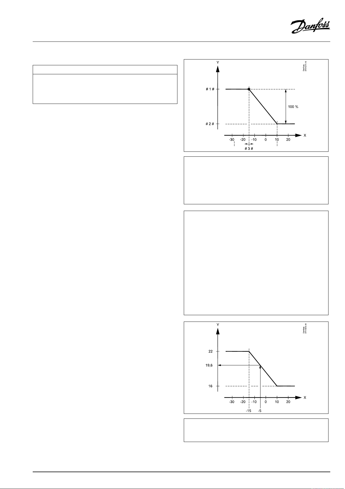
OperatingGuideECLComfort210/296/310,applicationA266
MENU>Settings>Optimization
Autosaving(savingtemp.dependentonoutdoortemp.)
Belowthesetvaluefortheoutdoortemperature,thesavingtemperature
settinghasnoinfluence.Abovethesetvaluefortheoutdoortemperature,
thesavingtemperaturerelatestotheactualoutdoortemperature.The
functionisrelevantindistrictheatinginstallationsinordertoavoidabig
changeinthedesiredflowtemperatureafterasavingperiod.
SeeAppendix“ParameterIDoverview”
OFF:
Thesavingtemperaturedoesnotdependonthe
outdoortemperature;thereductionis100%.
Value:Thesavingtemperaturedependsontheoutdoor
temperature.Whentheoutdoortemperatureisabove
10°C,thereductionis100%.Thelowertheoutdoor
temperature,thelessthetemperaturereduction.
Belowthesetvalue,thesavingtemperaturesetting
hasnoinfluence.
Comforttemperature:
Thedesiredroomtemperaturein
Comfortmode
Savingtemperature:
ThedesiredroomtemperatureinSaving
mode
ThedesiredroomtemperaturesforComfortandSavingmodes
aresetinthedisplayoverviews.
1x011
=
X
Y
#1#
#2#
#3#
Example:
Actualoutdoortemperature(T.out):
DesiredroomtemperaturesettinginComfortmode:
DesiredroomtemperaturesettinginSavingmode:
Settingin‘Autosaving’:
Outdoortemperature(°C)
=
Desiredroomtemperature(°C)
=
Desiredroomtemperature(°C),Comfortmode
=
Desiredroomtemperature(°C),Savingmode
=
Autosavingtemperature(°C),ID11011
–5°C
22°C
16°C
–15°C
Theconditionfortheoutdoortemperatureinfluence:
T.out.influence=(10-T.out)/(10-setting)=
(10-(-5))/(10-(-15))=
15/25=0,6
ThecorrecteddesiredroomtemperatureinSavingmode:
T.room.ref.Saving+(T.out.influencex(T.room.ref.ComfortT.room.ref.Saving))
16+(0,6x(22-16))=19,6°C
=
X
Y
Outdoortemperature(°C)
=
Desiredroomtemperature(°C)
AQ156586461753en-010601
©Danfoss|2021.06|89
Page 90

OperatingGuideECLComfort210/296/310,applicationA266
MENU>Settings>Optimization
Boost
Shortenstheheating-upperiodbyincreasingthedesiredflowtemperature
bythepercentageyouset.
SeeAppendix“ParameterIDoverview”
OFF:
Value:
Theboostfunctionisnotactive.
Thedesiredflowtemperatureisincreasedtemporarily
withthesetpercentage.
Inordertoshortentheheating-upperiodafterasaving
temperatureperiod,thedesiredflowtemperaturecanbeincreased
temporarily(max.1hour).Atoptimizingtheboostisactiveinthe
optimizationperiod('Optimizer').
IfaroomtemperaturesensororanECA30/31isconnected,the
booststopswhentheroomtemperatureisreached.
MENU>Settings>Optimization
Ramp(referenceramping)
Thetime(minutes)inwhichthedesiredflowtemperatureincreases
graduallytoavoidloadpeaksintheheatsupply.
SeeAppendix“ParameterIDoverview”
1x012
1x013
OFF:
Value:
Therampingfunctionisnotactive.
Thedesiredflowtemperatureisincreasedgraduallywith
thesetminutes.
Inordertoavoidloadpeaksinthesupplynetwork,theflow
temperaturecanbesettoincreasegraduallyafteraperiodwith
savingtemperature.Thiscausesthevalvetoopengradually.
=
X
Y
#1#
Time
=
Desiredflowtemperature
=
Rampingtime
=
Comforttemperature
=
Savingtemperature
90|©Danfoss|2021.06
AQ156586461753en-010601
Page 91

OperatingGuideECLComfort210/296/310,applicationA266
MENU>Settings>Optimization
Optimizer(optimizingtimeconstant)
Optimizesthestartandstoptimesforthecomforttemperatureperiodto
obtainthebestcomfortatthelowestenergyconsumption.
Thelowertheoutdoortemperature,theearliertheheatingcut-in.Thelower
theoutdoortemperature,thelatertheheatingcut-out.
Theoptimizedheatingcut-outtimecanbeautomaticordisabled.The
calculatedstartandstoptimesarebasedonthesettingoftheoptimizing
timeconstant.
SeeAppendix“ParameterIDoverview”
Adjusttheoptimizingtimeconstant.
Thevalueconsistsofatwodigitnumber.Thetwodigitshavethe
followingmeaning(digit1=TableI,digit2=TableII).
OFF:
Nooptimization.Theheatingstartsandstopsatthe
timessetintheschedule.
10...59:
SeetablesIandII.
TableI:
1x014
Systemtype
LeftdigitHeataccumulationofthe
building
Radiator
1-light
systems
2-medium
3-heavy
Floorheating
4-medium
systems
5-heavy
TableII:
RightdigitDimensioningtemperatureCapacity
-0-50°Clarge
-1
-45°C
-5
-25°C
normal
MENU>Settings>Optimization
Basedon(optimizationbasedonroom/outdoortemp.)
Theoptimizedstartandstoptimecanbebasedoneitherroomoroutdoor
temperature.
SeeAppendix“ParameterIDoverview”
OUT:
Optimizationbasedonoutdoortemperature.Usethis
settingiftheroomtemperatureisnotmeasured.
ROOM:
Optimizationbasedonroomtemperature,ifmeasured.
-9
Dimensioningtemperature:
Thelowestoutdoortemperature(usuallydeterminedbyyoursystem
designerinconnectionwiththedesignoftheheatingsystem)atwhich
theheatingsystemcanmaintainthedesignedroomtemperature.
Example
Thesystemtypeisradiator,andtheheataccumulationofthebuilding
ismedium.
Theleftdigitis2.
Thedimensioningtemperatureis-25°C,andthecapacityisnormal.
Therightdigitis5.
Result:
Thesettingistobechangedto25.
1x020
-5°C
small
AQ156586461753en-010601
©Danfoss|2021.06|91
Page 92

OperatingGuideECLComfort210/296/310,applicationA266
MENU>Settings>Optimization
Totalstop
Decidewhetheryouwantatotalstopduringthesavingtemperatureperiod.
1x021
SeeAppendix“ParameterIDoverview”
OFF:
Nototalstop.Thedesiredflowtemperatureisreduced
accordingto:
•desiredroomtemperatureinsavingmode
•autosaving
ON:
Thedesiredflowtemperatureisloweredtothesetvalue
in‘Frostpr. ’Thecirculationpumpisstoppedbutfrost
protectionisstillactive,see'PfrostT' .
Totalstop=OFF
Totalstop=ON
X
Y
=
Time
=
Desiredflowtemperature
=
Comforttemperature
=
Savingtemperature
=
Frostprotection
MENU>Settings>Optimization
Pre-stop(optimizedstoptime)
Disabletheoptimizedstoptime.
SeeAppendix“ParameterIDoverview”
OFF:
ON:
Theoptimizedstoptimeisdisabled.
Theoptimizedstoptimeisenabled.
Themin.flowtemperaturelimitation('Temp.min.')isoverruledwhen
'Totalstop'isON.
1x026
Example:OptimizationofComfortfrom07:00-22:00
=
X
#1#
#2#
#3#
#4#
#5#
Time
=
Schedule
=
Prestop=OFF
=
Prestop=ON
=
Optimizedstart
=
Optimizedstop
92|©Danfoss|2021.06
AQ156586461753en-010601
Page 93

OperatingGuideECLComfort210/296/310,applicationA266
MENU>Settings>Optimization
Paralleloperation
ChoosewhethertheheatingcircuitistooperateindependenceoftheDHW
circuit.Thisfunctionmightbeusefulifaninstallationhaslimitedpower
orflow.
SeeAppendix“ParameterIDoverview”
OFF:
Independentparalleloperation,i.e.theDHWand
theheatingcircuitsoperateindependentlyofeach
other.ItmakesnodifferencewhetherthedesiredDHW
temperaturecanbereachedornot.
Value:Dependentparalleloperation,i.e.thedesiredheating
temperaturedependsontheDHWdemand.Choose
howmuchtheDHWtemperaturecandropbeforethe
desiredheatingtemperaturehastobedecreased.
1x043
=
X
Y1
Y2
#1#
#2#
#3#
#4#
#5#
#6#
#7#
Time
=
Temperature
=
Temperature
=
Acceptabledeviation(Paralleloperation,1x043)
=
DesiredDHWtemperature
=
ActualDHWtemperature
=
Desiredheatingtemperature
=
Reducedheatingtemperature
=
100%paralleloperation
=
Paralleloperationwithdecreasedheatingtemperature
IftheactualDHWtemperaturedeviatesmorethanthesetvalue,the
gearmotorM2intheheatingcircuitwillgraduallyclosetosuchan
extentthattheDHWtemperaturestabilizesatthelowestacceptable
value.
IncasetheParalleloperationisactive(atoolowDHWtemperature
andthereforeareducedheatingcircuittemperature),aslave's
temperaturedemandwillnotchangethedesiredflowtemperaturein
theheatingcircuit.
Whendependentparalleloperationisinfunction:
•Desiredflowtemperaturefortheheatingcircuitwillbeminimum
limited,when"Priorityforreturntemperature"(ID1x085)isset
toOFF.
•Desiredflowtemperaturefortheheatingcircuitwillnotbe
minimumlimited,when"Priorityforreturntemperature"
(ID1x085)issettoON.
AQ156586461753en-010601
©Danfoss|2021.06|93
Page 94

OperatingGuideECLComfort210/296/310,applicationA266
MENU>Settings>Optimization
Summer,cut-out(limitforheatingcut-out)
1x179
SeeAppendix“ParameterIDoverview”
TheheatingcanbeswitchedOFFwhentheoutdoortemperatureis
higherthanthesetvalue.Thevalveclosesandafterthepost-run
time,theheatingcirculationpumpstops.‘Temp.min.’willbe
overruled.
TheheatingsystemswitchesONagainwhentheoutdoor
temperatureandtheaccumulated(filtered)outdoortemperature
becomelowerthanthesetlimit.
Thisfunctioncansaveenergy.
Setthevalueforoutdoortemperatureatwhichyouwantthe
heatingsystemtoswitchOFF .
Summer,cut-out
=
X
Y
#1#
#2#
#3#
#4#
#5#
Time
=
Temperature
=
Actualoutdoortemperature
=
Cut-outtemperature(1x179)
=
Accummulated(filtered)outdoortemperature
=
Heatingenabled
=
Heatingdisabled
Theheatingcut-outisonlyactivewhenthecontrollermodeisin
scheduledoperation.Whenthecut-outvalueissettoOFF,thereis
noheatingcut-out.
94|©Danfoss|2021.06
AQ156586461753en-010601
Page 95

OperatingGuideECLComfort210/296/310,applicationA266
5.7Controlparameters
Controlofvalves
Themotorizedcontrolvalvesarecontrolledbymeansof3-point
controlsignal.
Valvecontrol:
Themotorizedcontrolvalveisopenedgraduallywhentheflow
temperatureislowerthanthedesiredflowtemperatureandvice
versa.
Thewaterflowthroughthecontrolvalveismanagedbymeans
ofanelectricactuator.Thecombination"actuator"and"control
valve"isalsocalledmotorizedcontrolvalve.Theactuatorcanin
thiswaygraduallyincreaseordecreasetheflowinordertochange
thesuppliedenergy.Differenttypesofactuatorsareavailable.
3-pointcontrolledactuator:
Theelectricactuatorcontainsareversiblegear-motor.Electric
"open"and"close"signalscomefromtheelectronicoutputsofthe
ECLComfortcontrollerinordertomanagethecontrolvalve.The
signalsareintheECLComfortcontrollerexpressedas"Arrow-up"
(open)and"Arrow-down"(close)anddisplayedatthevalvesymbol.
Whentheflowtemperature(forexampleatS3)islowerthanthe
desiredflowtemperature,shortopen-signalscomefromtheECL
Comfortcontrollerinordertograduallyincreasetheflow.Bythis,
theflowtemperaturewillalignwiththedesiredtemperature.
Oppositely,whentheflowtemperatureishigherthanthedesired
flowtemperature,shortclose-signalscomefromtheECLComfort
controllerinordertograduallyreducetheflow.Again,theflow
temperaturealignswiththedesiredtemperature.
Neitheropen-signalsnorclose-signalswillcomeaslongastheflow
temperaturecorrespondstothedesiredtemperature.
0-10voltcontrolledactuator
Thiselectricactuatorcontainsareversiblegear-motor.Acontrol
voltagebetween0and10voltcomesfromtheextensionmodule
ECA32inordertomanagethecontrolvalve.ThevoltageintheECL
Comfortcontrollerisexpressedasa%valueanddisplayedatthe
valvesymbol.Example:45%correspondsto4.5volt.
Whentheflowtemperature(forexampleatS3)islowerthan
thedesiredflowtemperature,thecontrolvoltageisgradually
increasedinordertograduallyincreasetheflow.Bythis,theflow
temperaturewillalignwiththedesiredtemperature.
Thecontrolvoltageremainsonaconstantvalueaslongastheflow
temperaturecorrespondstothedesiredtemperature.
Oppositely,whentheflowtemperatureishigherthanthedesired
flowtemperature,thecontrolvoltageisgraduallyreducedinorder
toreducetheflow.Again,theflowtemperaturealignswiththe
desiredtemperature.
AQ156586461753en-010601
©Danfoss|2021.06|95
Page 96
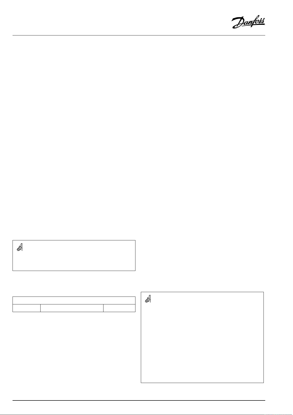
OperatingGuideECLComfort210/296/310,applicationA266
Thermo-hydraulicactuator,ABV
Danfossthermo-actuatortypeABVisaslowactingvalveactuator.
InsidetheABVanelectricheatcoilwillheatathermostaticelement
whenanelectricsignalisapplied.Whenheatingthethermostatic
elementitexpandsinordertomanagethecontrolvalve.
Twobasictypesareavailable:ABVNC(NormalClosed)andABVNO
(normalopen).Forexample,ABVNCkeepsa2-portcontrolvalve
closedwhennoopen-signalsareapplied.
Electricopen-signalscomefromtheelectronicoutputoftheECL
Comfortcontrollerinordertomanagethecontrolvalve.When
open-signalsareappliedtotheABVNC,thevalvegraduallyopens.
Open-signalsareintheECLComfortcontrollerexpressedas
"Arrow-up"(open)anddisplayedatthevalvesymbol.
Whentheflowtemperature(forexampleatS3)islowerthanthe
desiredflowtemperature,relativelylongopen-signalscomefrom
theECLComfortcontrollerinordertoincreasetheflow.Bythis,
theflowtemperaturewillovertimebealignedwiththedesired
temperature.
Oppositely,whentheflowtemperatureishigherthanthedesired
flowtemperature,relativelyshortopen-signalscomefromtheECL
Comfortcontrollerinordertoreducetheflow.Again,theflow
temperaturealigns,overtime,withthedesiredtemperature.
ThecontroloftheDanfossthermo-actuatortypeABVusesaunique
designedalgorithmandisbasedonthePWMprinciple(Pulse
WidthModulation),wherethedurationofthepulsedetermines
themanagementofthecontrolvalve.Thepulsesarerepeated
each10sec.
Aslongastheflowtemperaturecorrespondstothedesired
temperature,thedurationoftheopen-signalswillremainconstant.
ParametersindicatedwithanIDno.like"1x607"meanauniversal
parameter.
xstandsforcircuit/parametergroup.
MENU>Settings>Controlparameters
Actuator
ABV/GEAR
1x024
GEAR
Selectionofvalveactuatortype.
Whenselecting"ABV",thecontrolparameters:
•Motorprotection(ID1x174)
ABV:
GEAR:
96|©Danfoss|2021.06
DanfosstypeABV(thermoactuator).
Gearmotorbasedactuator.
•Xp(ID1x184)
•Tn(ID1x185)
•Mrun(ID1x186)
•Nz(ID1x187)
•Min.act.time(ID1x189)
arenotconsidered.
AQ156586461753en-010601
Page 97
OperatingGuideECLComfort210/296/310,applicationA266
MENU>Settings>Controlparameters
Opentime
The‘Opentime’istheforcedtime(inseconds)thatittakestoopenthe
motorizedcontrolvalvewhenaDHWdraw-off(tapping)isdetected(the
flowswitchisactivated).Thisfunctioncompensatesforthedelaybeforethe
flowtemperaturesensormeasuresachangeintemperature.
SeeAppendix“ParameterIDoverview”
MENU>Settings>Controlparameters
Closetime
The‘Closetime’istheforcedtime(inseconds)thatittakestoclosethe
motorizedcontrolvalvewhenaDHWdraw-off(tapping)isstopped(the
flowswitchisdeactivated).Thisfunctioncompensatesforthedelaybefore
theflowtemperaturesensormeasuresachangeintemperature.
SeeAppendix“ParameterIDoverview”
MENU>Settings>Controlparameters
Tn(idle)
WhennoDHWdraw-off(tapping)isdetected(theflowswitchisdeactivated),
thetemperatureismaintainedatalowlevel(savingtemperature).The
integrationtime‘Tn(idle)’canbesettoobtainaslowbutstablecontrol.
1x094
1x095
1x096
SeeAppendix“ParameterIDoverview”
MENU>Settings>Controlparameters
SupplyT(idle)
The‘supplyT(idle)’isthesupplytemperaturewhenthereisnoDHW
draw-off(tapping).WhenDHWdraw-offisnotdetected(theflowswitch
isdeactivated),thetemperatureismaintainedatalowerlevel(saving
temperature).Choosewhichtemperaturesensoristomaintainthesaving
temperature.
SeeAppendix“ParameterIDoverview”
OFF:
ThesavingtemperatureismaintainedattheDHWflow
temperaturesensor.
ON:
Thesavingtemperatureismaintainedatthesupply
temperaturesensor.
1x097
Ifthesupplytemperaturesensorisnotconnected,theidlesupply
temperaturewillbemaintainedattheDHWflowtemperaturesensor.
AQ156586461753en-010601
©Danfoss|2021.06|97
Page 98
OperatingGuideECLComfort210/296/310,applicationA266
MENU>Settings>Controlparameters
Autotuning
AutomaticallydeterminesthecontrolparametersfortheDHWcontrol.'Xp'
'Tn'and'Mrun'donotneedtobeset,whenusingautotuning.'Nz'must
beset.
1x173
SeeAppendix“ParameterIDoverview”
OFF:
ON:
Autotuningisnotactivated.
Autotuningisactivated.
Theautotuningfunctionautomaticallydeterminesthecontrol
parametersforDHWcontrol.Thusyoudonotneedtosetthe'Xp',
'Tn'and'Mrun',astheyareautomaticallysetwhentheautotuning
functionissettoON.
Autotuningistypicallyusedinconnectionwiththeinstallationof
thecontroller,butitcanbeactivatedwhenneeded,e.g.foran
extracheckofthecontrolparameters.
Beforestartingtheautotuning,thetappingflowshouldbe
adjustedtotherelevantvalue(seetable).
Ifpossible,anyadditionalDHWconsumptionshouldbeavoided
duringtheautotuningprocess.Shouldthetappingloadvarytoo
much,theautotuningandcontrollerwillreturntothedefault
settings.
No.of
apartments
Heat
transfer
ConstantDHWdraw-off(l/min)
(kW)
1-230-493
3-950-796
10-4980-14912
50-129150-24918
130-210250-35024
Inordertomeetthesummer-/wintervariations,theECLclockmust
besettothecorrectdateforansuccessfulautotuning.
Themotorprotectionfunction('Motorpr.')hastobedeactivated
duringautotuning.Duringautotuningthecirculationpumpfortap
watermustbeswitchedoff.Thisisdoneautomaticallyifthepumpis
controlledbytheECLcontroller.
Autotuningisonlyapplicableinconnectionwithvalvesthatare
approvedforautotuning,i.e.theDanfosstypesVB2andVM2with
splitcharacteristicaswellaslogarithmicvalvessuchasVFandVFS.
(or1tap25%open)
(or1tap50%open)
(or1tap100%open)
(or1tap100%+1tap50%
open)
(or2taps100%open)
AutotuningisactivatedbysettingthefunctiontoON.Whenthe
autotuningisended,thefunctionisautomaticallyconvertedto
OFF(defaultsetting).Thiswillbeindicatedinthedisplay.
Theautotuningprocesstakesupto25minutes.
MENU>Settings>Controlparameters
Motorpr.(motorprotection)
Preventsthecontrollerfromunstabletemperaturecontrol(andresulting
actuatoroscillations).Thiscanoccuratverylowload.Themotorprotection
increasesthelifetimeofallinvolvedcomponents.
SeeAppendix“ParameterIDoverview”
OFF:
Value:
Motorprotectionisnotactivated.
Motorprotectionisactivatedafterthesetactivation
delayinminutes.
MENU>Settings>Controlparameters
Xp(proportionalband)
SeeAppendix“ParameterIDoverview”
1x174
Recommendedforductsystemswithvariableload.
1x184
Settheproportionalband.Ahighervaluewillresultinastablebut
slowcontroloftheflowtemperature.
98|©Danfoss|2021.06
AQ156586461753en-010601
Page 99
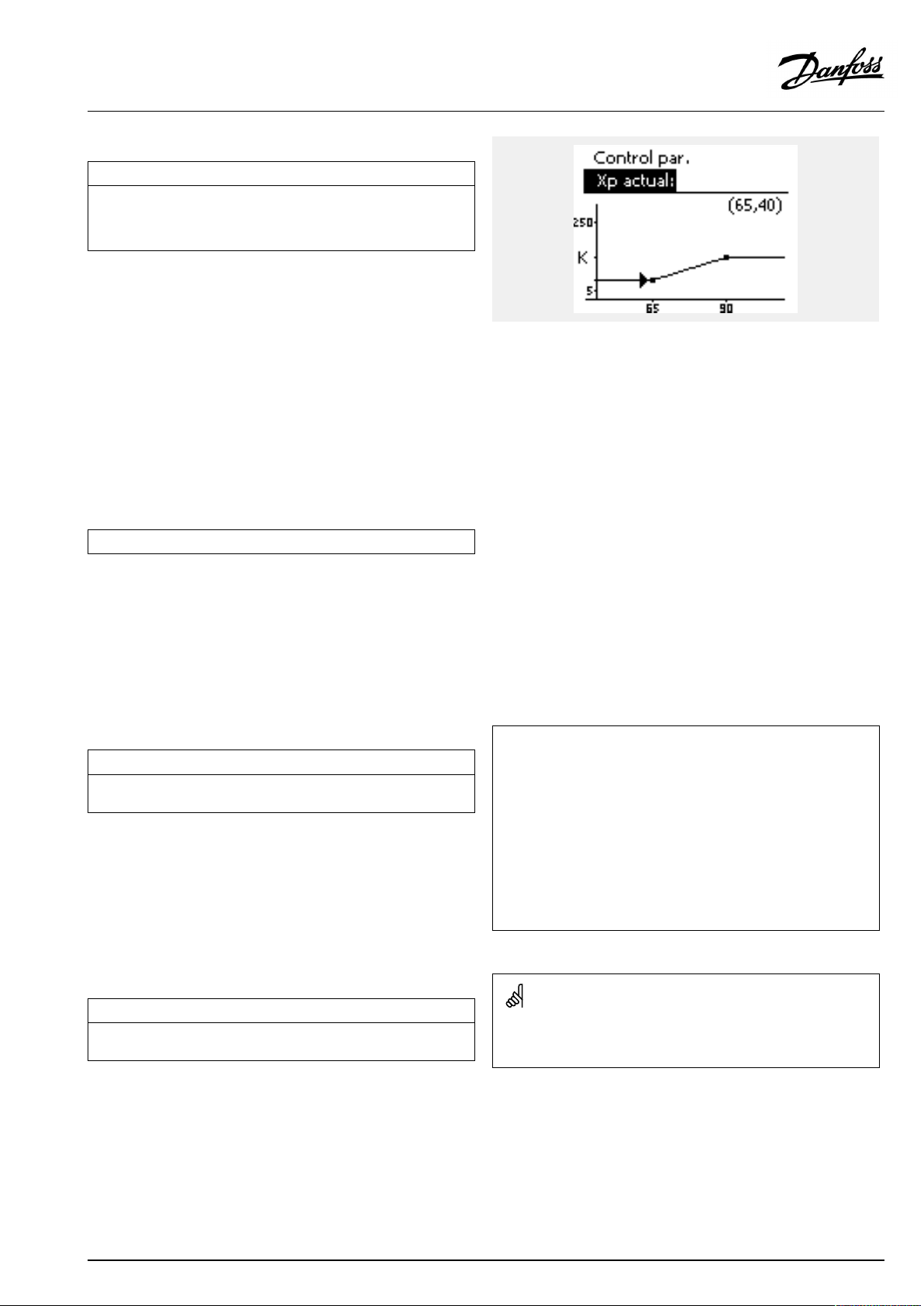
OperatingGuideECLComfort210/296/310,applicationA266
MENU>Settings>Controlparameters
Xpactual
‘Xpactual’istheread-outoftheactualXp(proportionalband)basedon
thesupplytemperature.Xpisdeterminedbysettingsrelatedtothesupply
temperature.Typically,thehigherthesupplytemperature,thehighertheXp
mustbeinordertoachieveastabletemperaturecontrol.
Xpsettingrange:
5...250K
Fixedsupplytemperaturesettings:65°Cand90°C
Factorysettings:
(65,40)and(90,120)
Thismeansthatthe‘Xp’is40Kat65°Csupplytemperature,and
‘Xp’is120Kat90°C.
SetthedesiredXpvaluesatthetwofixedsupplytemperatures.
Ifthesupplytemperatureisnotmeasured(thesupplytemperature
sensorisnotconnected),theXpvalueatthesetting65°Cisused.
MENU>Settings>Controlparameters
Tn(integrationtimeconstant)
1x185
SeeAppendix“ParameterIDoverview”
Setahighintegrationtimeconstant(inseconds)toobtainaslow
butstablereactiontodeviations.
Alowintegrationtimeconstantwillmakethecontrollerreactfast
butwithlessstability.
MENU>Settings>Controlparameters
Mrun(runningtimeofthemotorizedcontrolvalve)
‘Mrun’isthetimeinsecondsittakesthecontrolledcomponenttomove
fromfullyclosedtofullyopenposition.
SeeAppendix“ParameterIDoverview”
Setthe‘Mrun’accordingtotheexamplesormeasuretherunning
timebymeansofastopwatch.
MENU>Settings>Controlparameters
Nz(neutralzone)
Whentheactualflowtemperatureiswithintheneutralzone,thecontroller
doesnotactivatethemotorizedcontrolvalve.
SeeAppendix“ParameterIDoverview”
Settheacceptableflowtemperaturedeviation.
Settheneutralzonetoahighvalueifyoucanacceptahigh
variationinflowtemperature.
1x186
1x187
Howtocalculatetherunningtimeofamotorizedcontrolvalve
Therunningtimeofthemotorizedcontrolvalveiscalculatedusing
thefollowingmethods:
Seatedvalves
Runningtime=
Example:
Rotatingvalves
Runningtime=
Example:90degr.x2sec./degr.=180sec.
Theneutralzoneissymmetricalaroundthedesiredflowtemperature
value,i.e.halfthevalueisaboveandhalfthevalueisbelowthis
temperature.
Valvestroke(mm)xactuatorspeed(sec./mm)
5.0mmx15sec./mm=75sec.
Turningdegreesxactuatorspeed(sec./degr.)
AQ156586461753en-010601
©Danfoss|2021.06|99
Page 100

OperatingGuideECLComfort210/296/310,applicationA266
MENU>Settings>Controlparameters
Min.act.time(min.activationtimegearmotor)
Themin.pulseperiodof20ms(milliseconds)foractivationofthegear
motor.
SeeAppendix“ParameterIDoverview”
SettingexampleValuex20ms
1x189
240ms
10200ms
501000ms
Thesettingshouldbekeptashighasacceptabletoincreasethe
lifetimeoftheactuator(gearmotor).
100|©Danfoss|2021.06
AQ156586461753en-010601
 Loading...