

Page 1
OperatingGuide
ECLComfort210/296/310,applicationA237/A337
1.0TableofContents
1.0TableofContents...............................................1
1.1Importantsafetyandproductinformation.....................2
2.0Installation........................................................6
2.1Beforeyoustart.....................................................6
2.2Identifyingthesystemtype......................................13
2.3Mounting...........................................................16
2.4Placingthetemperaturesensors................................20
2.5Electricalconnections.............................................22
2.6InsertingtheECLApplicationKey..............................30
2.7Checklist............................................................37
2.8Navigation,ECLApplicationKeyA237/A337................38
3.0Dailyuse.........................................................44
3.1Howtonavigate...................................................44
3.2Understandingthecontrollerdisplay..........................45
3.3Ageneraloverview:Whatdothesymbolsmean?...........49
3.4Monitoringtemperaturesandsystem
components........................................................50
3.5Influenceoverview................................................51
3.6Manualcontrol.....................................................52
3.7Schedule............................................................53
4.0Settingsoverview............................................54
5.0Settings...........................................................57
5.1IntroductiontoSettings..........................................57
5.2Flowtemperature/Inlettemperature.........................58
5.3Roomlimit..........................................................62
5.4Returnlimit.........................................................64
5.5Flow/powerlimit.................................................70
5.6Optimization........................................................75
5.7Controlparameters................................................81
5.8Application.........................................................85
5.9Heatcut-out........................................................96
5.10Tanktemperature..................................................99
5.11Alarm..............................................................104
5.12Alarmoverview..................................................107
5.13Anti-bacteria......................................................108
6.0Commoncontrollersettings............................110
6.1Introductionto‘Commoncontrollersettings’..............110
6.2Time&Date.......................................................111
6.3Holiday............................................................112
6.4Inputoverview...................................................114
6.5Log.................................................................115
6.6Outputoverride..................................................116
6.7Keyfunctions.....................................................117
6.8System.............................................................119
7.0Miscellaneous................................................126
7.1ECA30/31setupprocedures.................................126
7.2Overridefunction................................................134
7.3Severalcontrollersinthesamesystem......................137
7.4Frequentlyaskedquestions....................................140
7.5Definitions........................................................143
7.6Type(ID6001),overview.......................................147
7.7Automatic/manualupdateoffirmware.....................148
7.8ParameterIDoverview..........................................149
©Danfoss|2021.02AQ000086479358en-010501|1
Page 2

OperatingGuideECLComfort210/296/310,applicationA237/A337
1.1Importantsafetyandproductinformation
1.1.1Importantsafetyandproductinformation
ThisOperatingGuideisassociatedwithECLApplicationKeyA237
(ordercodeno.087H3806).
TheECLApplicationKeyA237contains4subtypes:
•A237.1andA237.2(applicableinECLComfort210,296and310)
•A337.1andA337.2(applicableinECLComfort310)
•A237.1:HeatingandDHWheating
•A237.2:HeatingandDHWcharging
•A337.1:HeatingandDHWheating.Externalsetpointoptional
(0-10V)
•A337.2:HeatingandDHWcharging.Externalsetpointoptional
(0-10V)
TheA237applicationkeyalsocontainsaFloor(Screed)Drying
Program.Seeseparatedocumentation.(InEnglishandGerman
languageonly).
SeetheInstallationGuide(deliveredwiththeapplicationkey)for
applicationexamplesandelectricalconnections.
Thedescribedfunctionsarerealizedin:
•ECLComfort210forbasicsolutions
•ECLComfort296forbasicsolutions,M-busandEthernet
(Internet)communication
•ECLComfort310foradvancedsolutions,M-bus,Modbusand
Ethernet(Internet)communication.
TheApplicationKeyA237complieswithECLComfort210/310
controllersasoffirmwareversion1.11.
TheApplicationKeyA237compliesalsowithECLComfort296
controllersasoffirmwareversion1.58.
Thefirmware(controllersoftware)versionisvisibleatstart-upof
thecontrollerandin‘Commoncontrollersettings’in‘System’ .
UptotwoRemoteControlUnits,ECA30orECA31,canbe
connectedforremotemonitoringandsetting.Thebuilt-inroom
temperaturesensorcanbeutilized.
TogetherwiththeECLComfort310,theadditionalInternalI/O
moduleECA32(ordercodeno.087H3202)canbeusedforextra
datacommunicationtoSCADA:
•Temperature,Pt1000(default)
•0-10voltsignals
•Digitalinput
Theset-upofinputtypecanbedonebymeansoftheDanfoss
Software"ECLTool".
Navigation:Danfoss.com>Products&Solutions>DistrictHeating
andCooling>T ools&Software>ECLTool.
TheURLis:
https://www.danfoss.com/en/service-and-support/downloads/
2|©Danfoss|2021.02
AQ000086479358en-010501
Page 3
OperatingGuideECLComfort210/296/310,applicationA237/A337
TheInternalI/OmoduleECA32isplacedinthebasepartforECL
Comfort310.
ECLComfort210isavailableas:
•ECLComfort210,230volta.c.(087H3020)
•ECLComfort210B,230volta.c.(087H3030)
ECLComfort296isavailableas:
•ECLComfort296,230volta.c.(087H3000)
ECLComfort310isavailableas:
•ECLComfort310,230volta.c.(087H3040)
•ECLComfort310B,230volta.c.(087H3050)
•ECLComfort310,24volta.c.(087H3044)
TheB-typeshavenodisplayanddial.TheB-typesareoperatedby
meansoftheRemoteControlunitECA30/31:
•ECA30(087H3200)
•ECA31(087H3201)
BasepartsforECLComfort:
•forECLComfort210,230volt(087H3220)
•forECLComfort296,230volt(087H3240)
•forECLComfort310,230voltand24volt(087H3230)
AdditionaldocumentationforECLComfort210,296and310,
modulesandaccessoriesisavailableonhttp://heating.danfoss.com/.
DocumentationforECLPortal:Seehttp://ecl.portal.danfoss.com.
SafetyNote
Toavoidinjuryofpersonsanddamagestothedevice,itisabsolutely
necessarytoreadandobservetheseinstructionscarefully.
Necessaryassembly,start-up,andmaintenanceworkmustbe
performedbyqualifiedandauthorizedpersonnelonly.
Locallegislationsmustberespected.Thiscomprisesalsocable
dimensionsandtypeofisolation(doubleisolatedat230V).
AfusefortheECLComfortinstallationismax.10Atypically.
TheambienttemperaturerangesforECLComfortinoperationare:
ECLComfort210/310:0-55°C
ECLComfort296:0-45°C.
Exceedingthetemperaturerangecanresultinmalfunctions.
Installationmustbeavoidedifthereisariskforcondensation(dew).
Thewarningsignisusedtoemphasizespecialconditionsthatshould
betakenintoconsideration.
AQ000086479358en-010501
©Danfoss|2021.02|3
Page 4
OperatingGuideECLComfort210/296/310,applicationA237/A337
Thissymbolindicatesthatthisparticularpieceofinformationshould
bereadwithspecialattention.
Applicationkeysmightbereleasedbeforealldisplaytextsare
translated.InthiscasethetextisinEnglish.
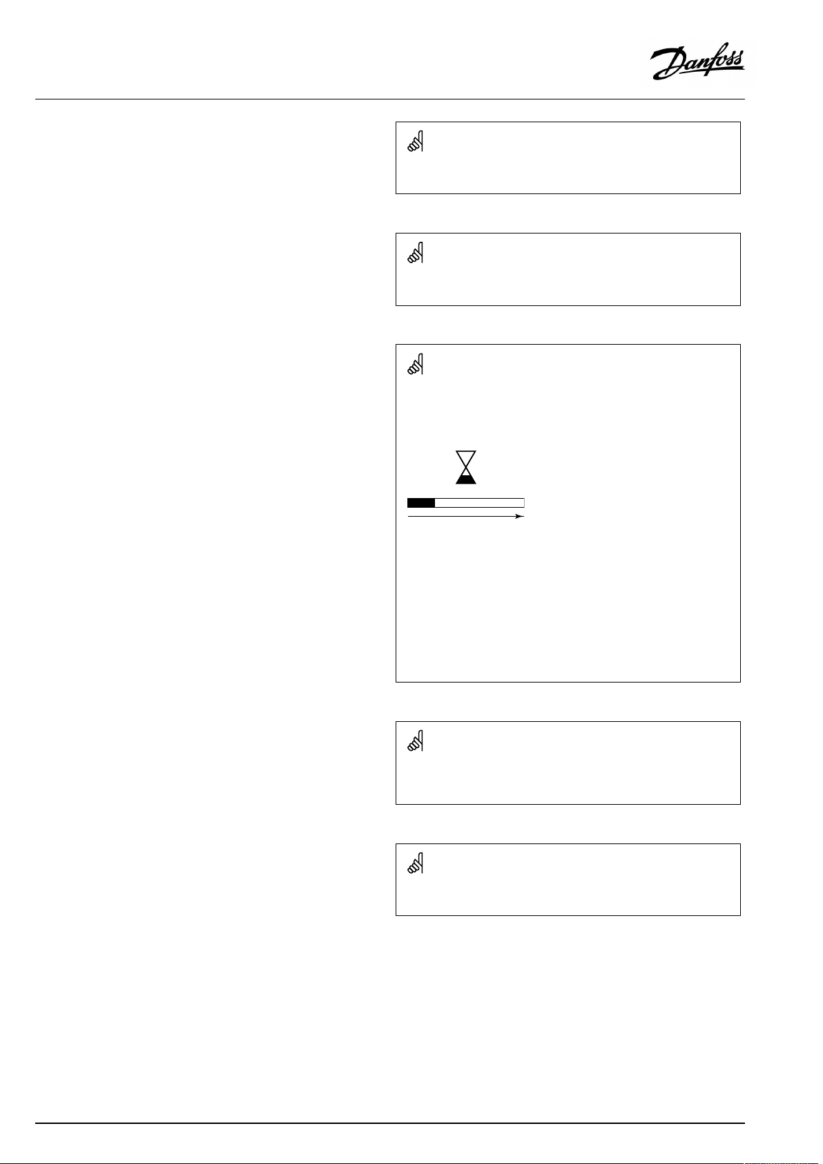
Automaticupdateofcontrollersoftware(firmware):
Thesoftwareofthecontrollerisupdatedautomaticallywhenthekey
isinserted(asofcontrollerversion1.11(ECL210/310)andversion
1.58(ECL296)).Thefollowinganimationwillbeshownwhenthe
softwareisbeingupdated:
Progressbar
Duringupdate:
•DonotremovetheKEY
Ifthekeyisremovedbeforethehour-glassisshown,youhave
tostartafresh.
•Donotdisconnectthepower
Ifthepowerisinterruptedwhenthehour-glassisshown,the
controllerwillnotwork.
•Manualupdateofcontrollersoftware(firmware):
Seethesection"Automatic/manualupdateoffirmware"
AsthisOperatingGuidecoversseveralsystemtypes,specialsystem
settingswillbemarkedwithasystemtype.Allsystemtypesareshown
inthechapter:'Identifyingyoursystemtype'.
°C(degreesCelsius)isameasuredtemperaturevaluewhereasK
(Kelvin)oftenisusedfortemperaturedifferences.
4|©Danfoss|2021.02
AQ000086479358en-010501
Page 5
OperatingGuideECLComfort210/296/310,applicationA237/A337
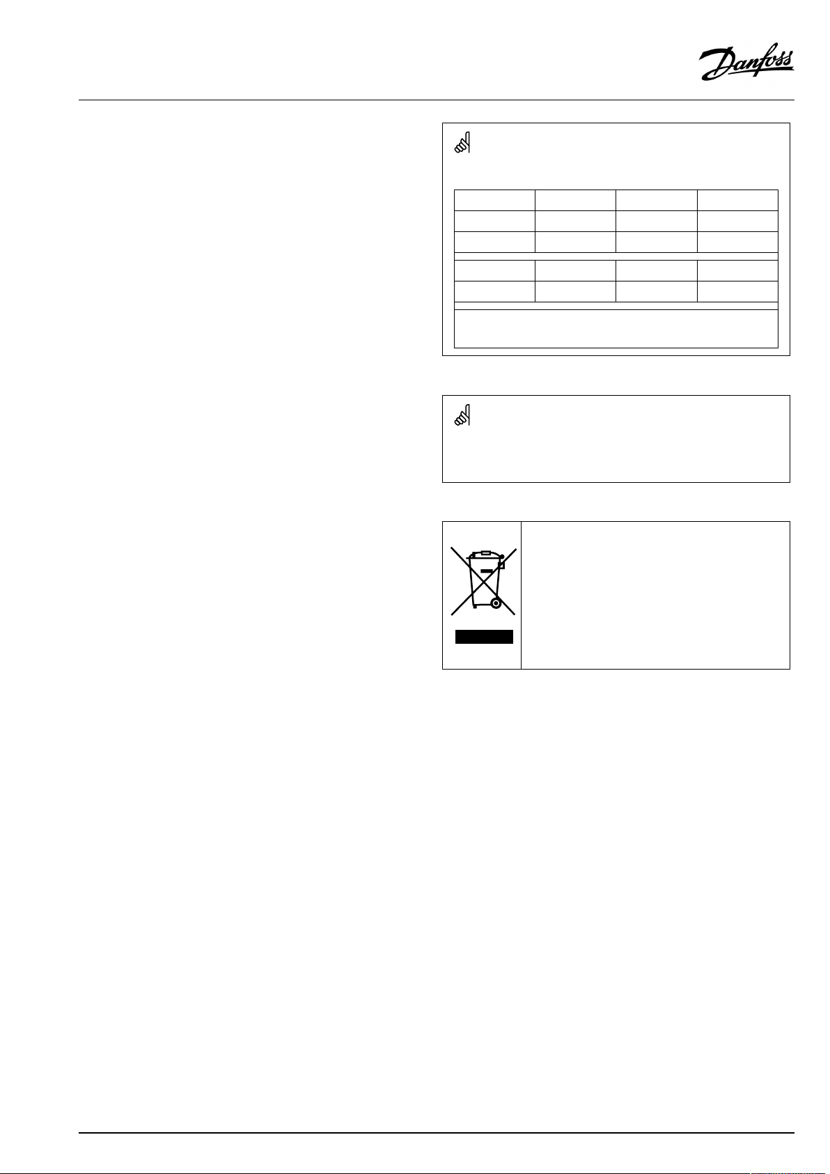
TheIDno.isuniquefortheselectedparameter.
ExampleFirstdigitSeconddigitLastthreedigits
1117411174
-
Circuit1Parameterno.
12174
IfanIDdescriptionismentionedmorethanonce,itmeansthatthere
arespecialsettingsforoneormoresystemtypes.Itwillbemarked
withthesystemtypeinquestion(e.g.12174-A266.9).
ParametersindicatedwithanIDno.like"1x607"meanauniversal
parameter.
xstandsforcircuit/parametergroup.
1
-
DisposalNote
Thissymbolontheproductindicatesthatitmaynot
bedisposedofashouseholdwaste.
Itmustbehandedovertotheapplicabletake-back
schemefortherecyclingofelectricalandelectronic
equipment.
•Disposeoftheproductthroughchannelsprovided
forthispurpose.
•Complywithalllocalandcurrentlyapplicablelaws
andregulations.
2
Circuit2Parameterno.
174
AQ000086479358en-010501
©Danfoss|2021.02|5
Page 6
OperatingGuideECLComfort210/296/310,applicationA237/A337
2.0Installation
2.1Beforeyoustart
Thetwoapplications,A237.1/A337.1arealmostidentical.
However,A337.1hassomeextrafunctionswhicharedescribed
additionally.
TheapplicationsA237.1/A337.1areveryflexible.Thesearethe
basicprinciples:
Heating(circuit1):
Typically,theflowtemperatureisadjustedaccordingtoyour
requirements.TheflowtemperaturesensorS3isthemost
importantsensor.ThedesiredflowtemperatureatS3iscalculated
intheECLcontroller,basedontheoutdoortemperature(S1)and
thedesiredroomtemperature.
Thelowertheoutdoortemperature,thehigherthedesiredflow
temperature.
Bymeansofaweekschedule,theheatingcircuitcanbein
‘Comfort’or‘Saving’mode.Theweekschedulecanhaveupto3
‘Comfort’periods/day.Avalueforthedesiredroomtemperature
canbesetineachofthemodes.
InSavingmodetheheatingcanbereducedorswitchedofftotally.
ThemotorizedcontrolvalveM1isopenedgraduallywhenthe
flowtemperatureislowerthanthedesiredflowtemperatureand
viceversa.
ThereturntemperatureS5canbelimited,forexamplenottobe
toohigh.Ifso,thedesiredflowtemperatureatS3canbeadjusted
(typicallytoalowervalue),thusresultinginagradualclosingof
themotorizedcontrolvalve.Furthermore,thereturntemperature
limitationcanbedependentontheoutdoortemperature.
Typically,thelowertheoutdoortemperature,thehigherthe
acceptedreturntemperature.Inboiler-basedheatingsupplythe
returntemperatureshouldnotbetoolow(sameadjustment
procedureasabove).
Ifthemeasuredroomtemperature(directlyconnectedtemperature
sensorESM-10(S2)orRemotecontrolunitECA30/31)doesnot
equalthedesiredroomtemperature,thedesiredflowtemperature
canbeadjusted.
ThecirculationpumpP1isONatheatdemandoratfrost
protection.ThecirculationpumpP1canbeswitchedOFFwhen
heatingtheDHW.Ifthesystemhasachangeovervalve(P2/M2)
betweentheheatingandDHWcircuit,thecirculationpumpP1
isONwhenheatingtheDHW.
TheheatingcanbeswitchedOFFwhentheoutdoortemperatureis
higherthanaselectablevalue.
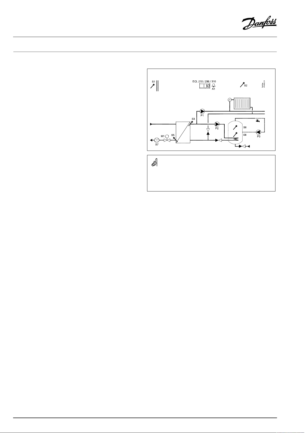
TypicalA237.1/A337.1application:
Theshowndiagramisafundamentalandsimplifiedexampleanddoes
notcontainallcomponentsthatarenecessaryinasystem.
AllnamedcomponentsareconnectedtotheECLComfortcontroller.
Listofcomponents:
ECL210/296/
310
S1
S2Roomtemperaturesensor
S3
S5Returntemperaturesensor,circuit1
S6
S7
S8
P1
P2DHWpump,circuit2
P3
M1
A1
ElectroniccontrollerECLComfort210,296or310
Outdoortemperaturesensor
Flowtemperaturesensor,circuit1
DHWtanktemperaturesensor,upper
Flow/energymeter(pulsesignal)
DHWtanktemperaturesensor,lower
Circulationpump,heating,circuit1
DHWcirculationpump,circuit2
Motorizedcontrolvalve(3-pointcontrolled).
Alternative:Thermoactuator(DanfosstypeABV)
Alarm
Aconnectedfloworenergymeterbasedonpulses(S7)canlimit
thefloworenergytoasetmaximumvalue.Furthermore,the
limitationcanbeinrelationtotheoutdoortemperature.
Typically,thelowertheoutdoortemperature,thehigherthe
acceptedflow/power.
Thefrostprotectionmodemaintainsaselectableflowtemperature
value,forexample10°C.
Analarmcanbeactivatediftheactualflowtemperaturediffers
fromthedesiredflowtemperature.
6|©Danfoss|2021.02
AQ000086479358en-010501
Page 7

OperatingGuideECLComfort210/296/310,applicationA237/A337
A237.1,ex.a,A337.1,ex.a
DuringDHWheating,thecirculationpumpP1intheheatingcircuit
can:
•beswitchedOFF(DHWprioritymode)
or
•remainON,aslongastheheatingtemperatureatS3doesnot
differmorethanasetvaluefromthedesiredtemperature
(dependentparallelmode)
or
•becontinuouslyON.Thismeanssametemperatureinthe
heatingcircuitastheDHWheatingtemperature(parallel
mode).
A237.1usedinECL296/310
Theflow/powersignalcancomeasapulsesignaloranM-bus
signal.
A337.1
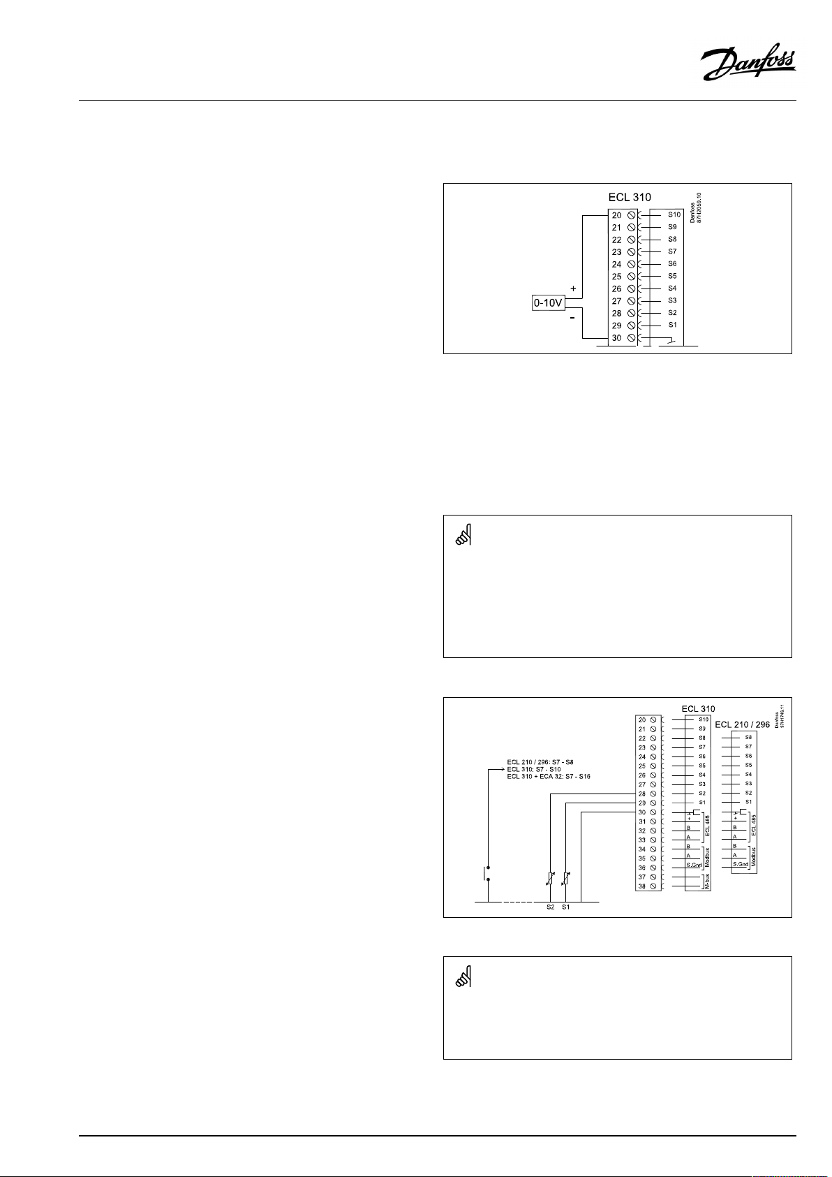
Thedesiredflowtemperatureoftheheatingcircuitcan,viaS10,be
controlledbymeansofanexternalvoltageintherange0-10volt.
ModbuscommunicationtoaSCADAsystemcanbeestablished.
AconnectedfloworenergymeterbasedonM-bussignalcan
limitthefloworpowertoasetmaximumvalue.Furthermore,the
limitationcanbeinrelationtotheoutdoortemperature.
Typically,thelowertheoutdoortemperature,thehigherthe
acceptedflow/power.
M-busdatacanbetransferredtotheModbuscommunication.
Heatingingeneral
Exerciseofcirculationpumpsandcontrolvalveinperiodswithout
heatingdemandcanbearranged.
AQ000086479358en-010501
©Danfoss|2021.02|7
Page 8
OperatingGuideECLComfort210/296/310,applicationA237/A337
DHW(circuit2):
Bymeansofaweekschedule,theDHWcircuitcanbein‘Comfort’
or‘Saving’mode.Theweekschedulecanhaveupto3‘Comfort’
periods/day.AvalueforthedesiredDHWtemperaturecanbe
setineachofthemodes.
DHWheatingstart,DHWtankwith1or2temperaturesensors
WhenthemeasuredDHWtemperatureS6getslowerthanthestart
temperature,theheatingcirculationpumpP1isswitchedOFFand
theDHWheatingpumpP2isswitchedON.
ThemotorizedcontrolvalveM1iscontrolledinordertomaintain
theheatingtemperatureatS3.
AdelayedstartoftheDHWheatingpumpcanbearranged.Inthis
case,S3mustbeplacedintheheat-exchanger.
TheDHWheatingtemperatureisdeterminedbythedesiredDHW
temperatureatS6plusthesetchargingdifference.Thecharging
temperatureistypically5-10degreeshigherthanthedesired
DHWtemperature.
ThereturntemperatureS5,whentheDHWheating/chargingis
active,canbelimitedtoasetvalue.
Chargingstop,DHWtankwith1temperaturesensor
WhenthemeasuredDHWtemperatureS6getshigherthanthe
charging-stoptemperature,theDHWheatingpumpP2isswitched
OFF.Apost-runtimecanbeset.
Chargingstop,DHWtankwith2temperaturesensors
A237.1/A337.1examplea:
A237.1/A337.1exampleb:
A237.1/A337.1examplec:
WhenthemeasuredDHWtemperatureS6gets2Khigherthanthe
heating-starttemperatureANDthelowertanktemperatureS8gets
higherthantheheating-stoptemperature,theDHWheatingpump
P2isswitchedOFF.Apost-runtimecanbeset.
Iftheinstallationhasachangeovervalve(P2/M2),alsocalled
priority-valve,betweentheheatingandtheDHWcircuits,the
changeovervalveisactivatedatDHWheatingdemand.The
circulationpump(P1)isONwhenheatingtheDHW.
Parallelmodeintwo-pumpapplications:
Ifthechargingtemperaturehasavalueclosetothedesiredflow
temperatureintheheatingcircuit,thecirculationpump(P1)inthe
heatingcircuitwillnotbeswitchedOFFduringDHWheating.
Ananti-bacteriafunctionisavailableforactivationonselected
daysoftheweek.
TheDHWcircuitcanbeconnectedprimarilyandthevalve‘P2/
M2’operatesasON/OFFvalve.
TheDHWcirculationpump(P3)hasaweekscheduleforupto3
ON-periods/day.
TheDHWcirculationpumpP3canbeswitchedOFFduringDHW
heating/charging.
A237.1/A337.1exampled:
8|©Danfoss|2021.02
AQ000086479358en-010501
Page 9
OperatingGuideECLComfort210/296/310,applicationA237/A337
ApplicationA237.1andA337.1,ingeneral
Unusedinputcan,bymeansofanoverrideswitch,beusedto
overridethescheduletoafixed'Comfort'or'Saving'mode.
ModbuscommunicationtoaSCADAsystemcanbeestablished.
InECLComfort296/310theM-busdatacanfurthermorebe
transferredtotheModbuscommunication.
Thetwoapplications,A237.2/A337.2arealmostidentical.
However,A337.2hassomeextrafunctionswhicharedescribed
additionally.
TheapplicationsA237.2/A337.2areveryflexible.Thesearethe
basicprinciples:
Heating(circuit1):
Theheatingcircuitworksasdescribedpreviously.
A237.2,ex.a,A337.2,ex.a
DuringDHWheating,thecirculationpumpP1intheheatingcircuit
can:
•beswitchedOFF(DHWprioritymode)
or
•remainON,aslongastheheatingtemperatureatS3doesnot
differmorethanasetvaluefromthedesiredtemperature
(dependentparallelmode)
or
•becontinuouslyON.Thismeanssametemperatureinthe
heatingcircuitastheDHWheatingtemperature(parallel
mode).
A237.2usedinECL296
Theflow/powersignalcancomeasapulsesignaloranM-bus
signal.
A337.2
Thedesiredflowtemperatureoftheheatingcircuitcan,viaS10,be
controlledbymeansofanexternalvoltageintherange0-10volt.
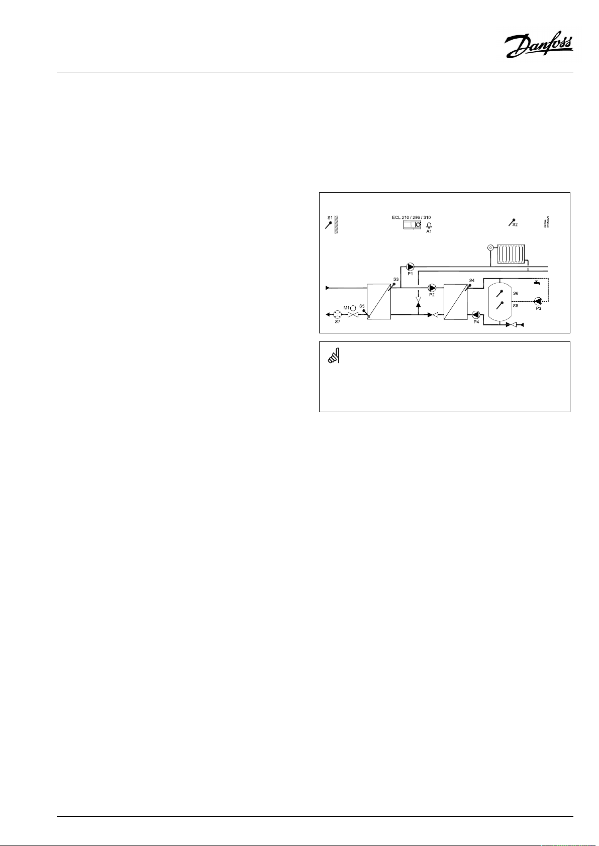
TypicalA237.2/A337.2application:
Theshowndiagramisafundamentalandsimplifiedexampleanddoes
notcontainallcomponentsthatarenecessaryinasystem.
AllnamedcomponentsareconnectedtotheECLComfortcontroller.
Listofcomponents:
ECL210/296/
ElectroniccontrollerECLComfort210,296or310
310
S1
Outdoortemperaturesensor
S2Roomtemperaturesensor
S3
Flowtemperaturesensor,circuit1
S5Returntemperaturesensor,circuit1
S6
S7
S8
P1
DHWtanktemperaturesensor,upper
Flow/energymeter(pulsesignal)
DHWtanktemperaturesensor,lower
Circulationpump,heating,circuit1
P2DHWpump,circuit2
P3
P4
M1
DHWcirculationpump,circuit2
DHWchargingpump,circuit2
Motorizedcontrolvalve(3-pointcontrolled).
Alternative:Thermoactuator(DanfosstypeABV).
A1
Alarm(A337.2only)
AQ000086479358en-010501
©Danfoss|2021.02|9
Page 10
OperatingGuideECLComfort210/296/310,applicationA237/A337
DHW(circuit2):
Bymeansofaweekschedule,theDHWcircuitcanbein‘Comfort’
or‘Saving’mode.Theweekschedulecanhaveupto3‘Comfort’
periods/day.AvalueforthedesiredDHWtemperature
canbesetineachofthemodes.
DHWchargingstart,DHWtankwith1or2temperaturesensors
WhenthemeasuredDHWtemperatureS6getslowerthanthe
charging-starttemperature,theheatingcirculationpumpP1is
switchedOFFandtheDHWheatingpumpP2isswitchedON.
AdelayedstartoftheDHWchargingpumpP4canbearranged.
Also,itcanbearrangedthatthestartofthechargingpump
dependsontheDHWheatingtemperature.Inthiscase,S4mustbe
placedintheheat-exchanger.
TheDHWheatingtemperatureisdeterminedbythedesiredDHW
temperatureatS6plusthesetchargingdifference.Thecharging
temperatureistypically5-10degreeshigherthanthedesired
DHWtemperature.
ThereturntemperatureS5,whentheDHWheating/chargingis
active,canbelimitedtoasetvalue.
TheDHWheatingtemperatureatS3isadaptedtothedesiredDHW
chargingtemperatureatS4.IftheDHWchargingtemperatureat
S4cannotbereached,theECLcontrollergraduallyincreasesthe
desiredDHWheatingtemperatureatS3inordertoobtaintheDHW
chargingtemperature.TheECLcontrollerrememberstheadapted
S3temperature.Amaximumtemperaturevaluecanbeset.
A237.2/A337.2examplea:
A237.2/A337.2exampleb:
ThemotorizedcontrolvalveM1iscontrolledinordertomaintain
thechargingtemperatureatS4.
DHWchargingstop,DHWtankwith1temperaturesensor
WhenthemeasuredDHWtemperatureS6getshigherthan
thecharging-stoptemperature,theDHWchargingpumpP4is
switchedOFF.Apost-runtimecanbeset.
Chargingstop,DHWtankwith2temperaturesensors
WhenthemeasuredDHWtemperatureS6gets2Khigherthan
thecharging-starttemperatureANDthelowertanktemperature
S8getshigherthanthecharging-stoptemperature,theDHW
chargingpumpP4isswitchedOFF.Apost-runtimecanbeset.
Iftheinstallationhasachangeovervalve(P2/M2),alsocalled
priority-valve,betweentheheatingandtheDHWcircuits,the
changeovervalveisactivatedatDHWheatingdemand.The
circulationpump(P1)isONwhenheatingtheDHW.
Parallelmodeintwo-pumpapplications:
Ifthechargingtemperaturehasavalueclosetothedesiredflow
temperatureintheheatingcircuit,thecirculationpump(P1)inthe
heatingcircuitwillnotbeswitchedOFFduringDHWheating.
Ananti-bacteriafunctionisavailableforactivationonselected
daysoftheweek.
TheDHWcirculationpump(P3)hasaweekscheduleforupto3
ON-periodsperday.
10|©Danfoss|2021.02
AQ000086479358en-010501
Page 11

OperatingGuideECLComfort210/296/310,applicationA237/A337
ApplicationA237.2andA337.2,ingeneral:
Unusedinputcan,bymeansofanoverrideswitch,beusedto
overridethescheduletoafixed'Comfort'or'Saving'mode.
ModbuscommunicationtoaSCADAsystemcanbeestablished.In
ECLComfort310theM-busdatacanfurthermorebetransferred
totheModbuscommunication.
A237,ingeneral
Flow/energylimitation.
ECLComfort210:
ThesubtypesA237.1andA237.2canutilizetheflow/powersignal
comingasapulsesignal.
ECLComfort296:
ThesubtypesA237.1andA237.2canutilizetheflow/powersignal
comingasapulsesignaloranM-bussignal.
ECLComfort310:
ThesubtypesA337.1andA337.2canutilizetheflow/powersignal
comingasanM-bussignal.
Alarm
A237.1:
AlarmA1(=relay4)canbeactivated:
•iftheactualflowtemperaturediffersfromthedesiredflow
temperature
•ifatemperaturesensororitsconnectiondisconnects/short
circuits.(See:Commoncontrollersettings>System>Raw
inputoverview)
A237.2:
Noalarmfunctionpresent
A337.1,A337.2:
AlarmA1(=relay6)canbeactivated:
•iftheactualflowtemperaturediffersfromthedesiredflow
temperature
•ifatemperaturesensororitsconnectiondisconnects/short
circuits.(See:Commoncontrollersettings>System>Raw
inputoverview)
Inputconfiguration
Inputs(asfromS7andup)whicharenotpartoftheapplication
canbeconfiguredtobePt1000,0-10VoltorDigitalinput.This
featuremakesitpossibletocommunicateextrasignals,suchas
temperatures,pressures,ON/OFFconditions,viaModbusand
ECLPortal.
TheconfigurationisdonebymeansoftheECLTool(freesoftware
fordownload)ordirectlyinadedicatedmenuintheECLPortal.
Dependingonsystemtype,itisrecommendedtochangesome
factorysettingsindividuallyinordertooptimizethefunctionality.
Thesesettingchanges,ifrequired,arelistedbelowthesystem
typesinthesection'Identifyingthesystemtype'.
WhentheA237hasbeenuploadedtheECLComfortcontroller
startsinManualmode.Thiscanbeusedforcheckingthecontrolled
componentsforcorrectfunctionality.
AQ000086479358en-010501
©Danfoss|2021.02|11
Page 12

OperatingGuideECLComfort210/296/310,applicationA237/A337
Thecontrollerispre-programmedwithfactorysettingsthatareshown
inthe‘ParameterIDoverview’appendix.
12|©Danfoss|2021.02
AQ000086479358en-010501
Page 13
OperatingGuideECLComfort210/296/310,applicationA237/A337
2.2Identifyingthesystemtype
Sketchyourapplication
TheECLComfortcontrollerseriesisdesignedforawiderange
ofheating,domestichot-water(DHW)andcoolingsystemswith
differentconfigurationsandcapacities.Ifyoursystemdiffers
fromthediagramsshownhere,youmaywanttomakeasketch
ofthesystemabouttobeinstalled.Thismakesiteasiertouse
theOperatingGuide,whichwillguideyoustep-by-stepfrom
installationtofinaladjustmentsbeforetheend-usertakesover.
TheECLComfortcontrollerisauniversalcontrollerthatcanbe
usedforvarioussystems.Basedontheshownstandardsystems,
itispossibletoconfigureadditionalsystems.Inthischapteryou
findthemostfrequentlyusedsystems.Ifyoursystemisnotquite
asshownbelow,findthediagramwhichhasthebestresemblance
withyoursystemandmakeyourowncombinations.
SeetheInstallationGuide(deliveredwiththeapplicationkey)for
applicationtypes/sub-types.
Thecirculationpump(s)inheatingcircuit(s)canbeplacedintheflow
aswellasthereturn.Placethepumpaccordingtothemanufacturer’s
specification.
AQ000086479358en-010501
©Danfoss|2021.02|13
Page 14
OperatingGuideECLComfort210/296/310,applicationA237/A337
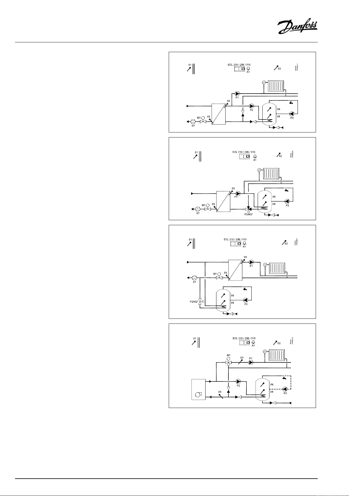
Adviceforsettings:
Factorysettingsinthesubtypeswillrunthemostapplication
examples.Someoftheapplicationexamplesneedchangeof
dedicatedsettings.
Seethedocumentationforapplicationsandsubtypes,delivered
withtheapplicationkey.
A237.1,ex.a
A337.1,ex.a
Twopumpsystem:
Issue:
DHWcircuit(2):
Pump
A237.1,ex.b
A337.1,ex.b
OnepumpandChange-overvalvesystem:
Issue:
DHWcircuit(2):
Change-overvalve
A237.1,ex.c
A237.1,ex.d
A337.1,ex.c
A337.1,ex.d
DHWheatingconnectedprimarily:
Issue:
DHWcircuit(2):
Change-overvalve
DHWcircuit(2):
Tankprimarily
Navigation:
MENU\Settings\Application:
'Ch.-o.valve/P'
Navigation:
MENU\Settings\Application:
'Ch.-o.valve/P'
Navigation:
MENU\Settings\Application:
'Ch.-o.valve/P'
MENU\Settings\Application:
'Tank,sec./prim'
IDno.:
12051
IDno.:
12051
IDno.:
12051
12053
Recommended
setting:
ON
Recommended
setting:
OFF
Recommended
setting:
OFF
ON
14|©Danfoss|2021.02
AQ000086479358en-010501
Page 15
OperatingGuideECLComfort210/296/310,applicationA237/A337
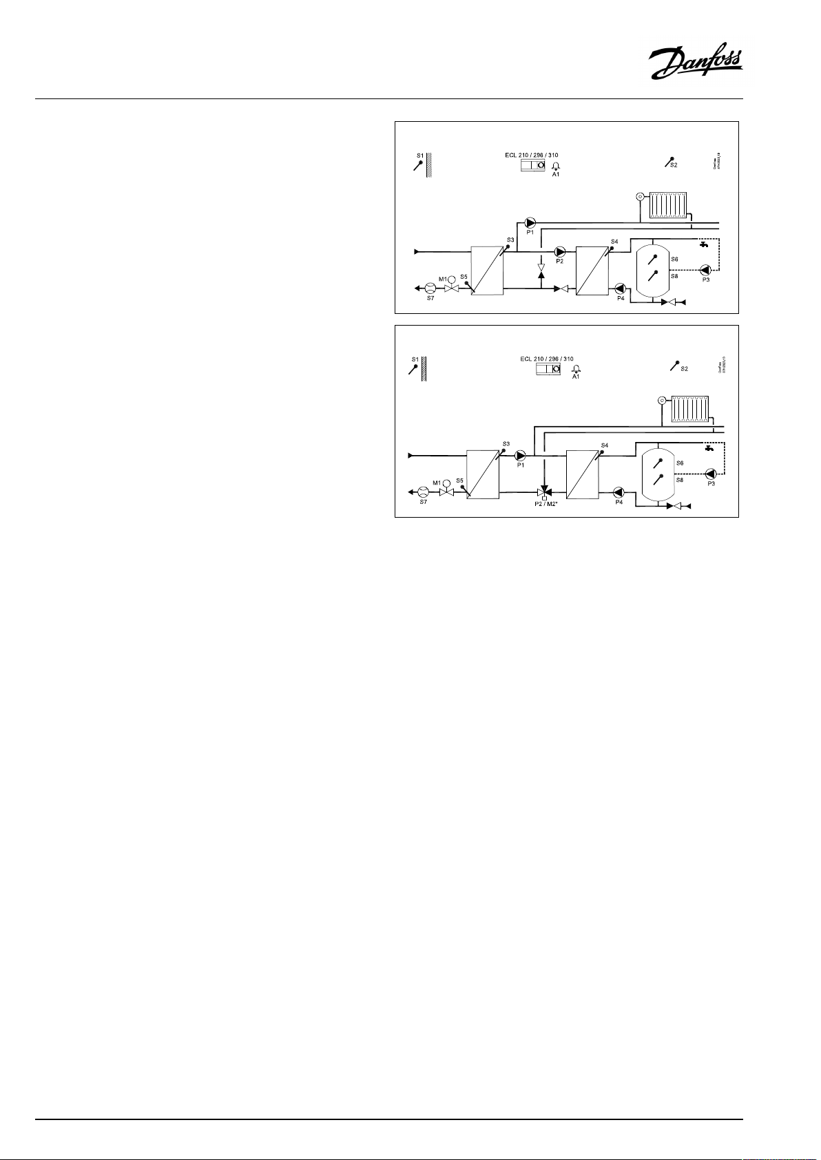
Adviceforsettings:
A237.2,ex.a
A337.2,ex.a
Twopumpsystem:
Issue:
DHWcircuit(2):
Pump
A237.2,ex.b
A337.2,ex.b
OnepumpandChange-overvalvesystem:
Issue:
DHWcircuit(2):
Pump
Navigation:
MENU\Settings\Application:
'Ch.-o.valve/P'
Navigation:
MENU\Settings\Application:
'Ch.-o.valve/P'
IDno.:
12051
IDno.:
12051
Recommended
setting:
ON
Recommended
setting:
OFF
AQ000086479358en-010501
©Danfoss|2021.02|15
Page 16
OperatingGuideECLComfort210/296/310,applicationA237/A337
2.3Mounting
2.3.1MountingtheECLComfortcontroller
SeetheInstallationGuidewhichisdeliveredtogetherwiththe
ECLComfortcontroller.
Foreasyaccess,youshouldmounttheECLComfortcontrollernear
thesystem.
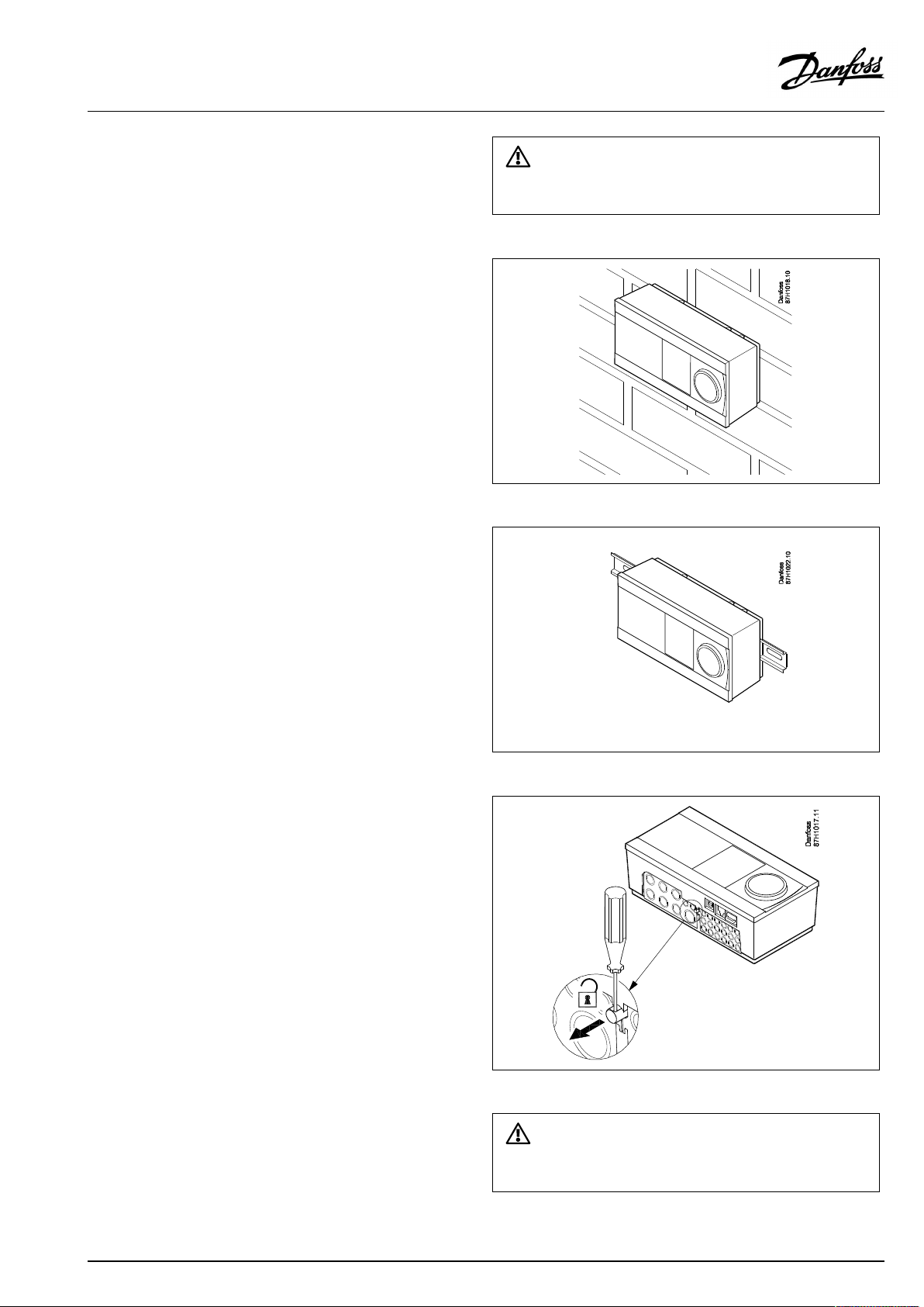
ECLComfort210/296/310canbemounted
•onawall
•onaDINrail(35mm)
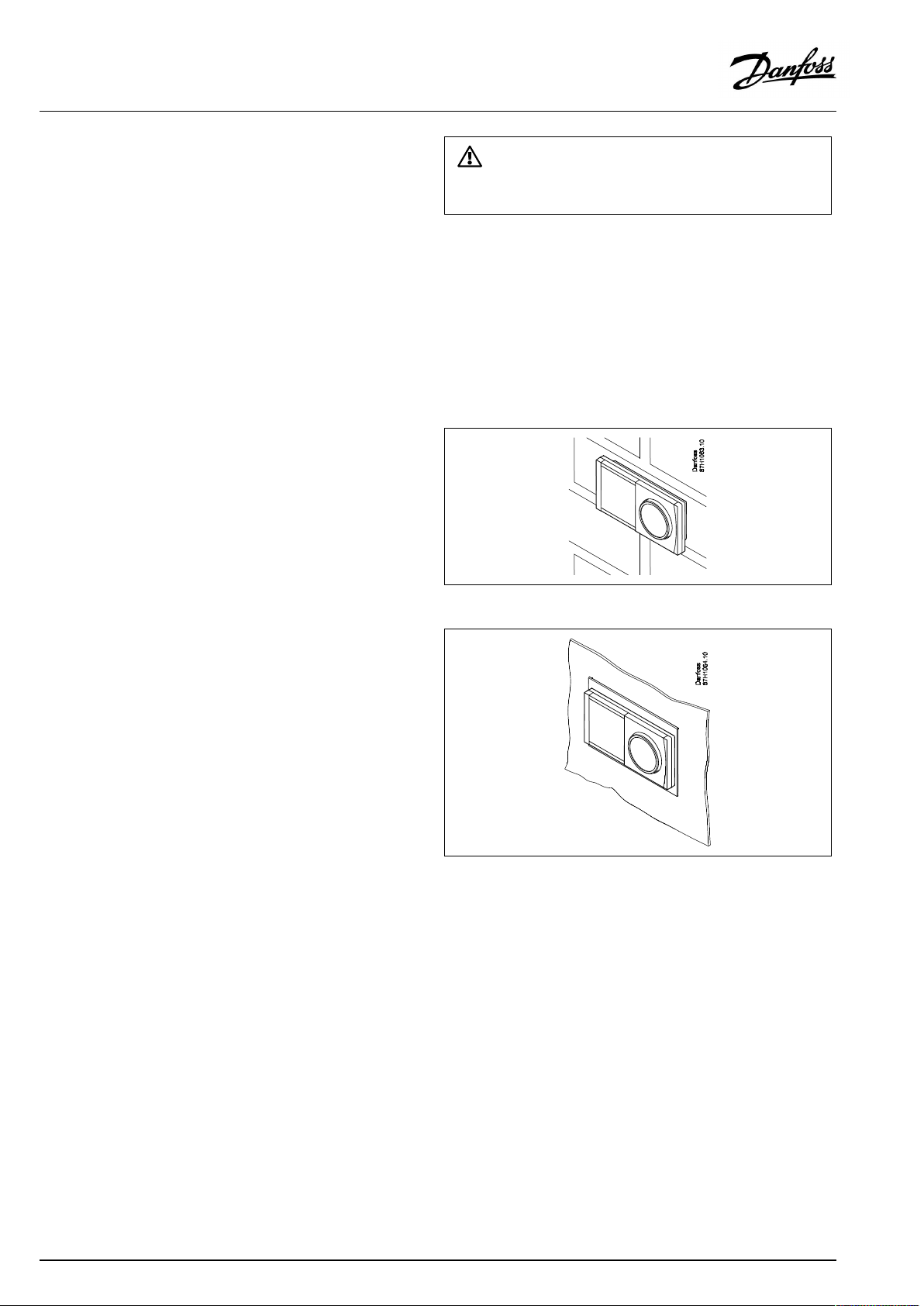
ECLComfort296canbemounted
•inapanelcut-out
ECLComfort210canbemountedinanECLComfort310basepart
(forfutureupgrade).
Screws,PGcableglandsandrawlplugsarenotsupplied.
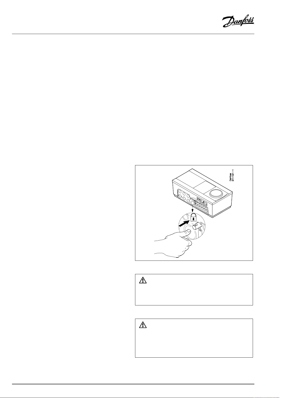
LockingtheECLComfort210/310controller
InordertofastentheECLComfortcontrollertoitsbasepart,secure
thecontrollerwiththelockingpin.
16|©Danfoss|2021.02
Topreventinjuriestopersonsorthecontroller,thecontrollerhasto
besecurelylockedintothebase.Forthispurpose,pressthelocking
pinintothebaseuntilaclickisheardandthecontrollernolonger
canberemovedfromthebase.
Ifthecontrollerisnotsecurelylockedintothebasepart,thereisarisk
thatthecontrollerduringoperationcanunlockfromthebaseandthe
basewithterminals(andalsothe230Va.c.connections)areexposed.
Topreventinjuriestopersons,alwaysmakesurethatthecontroller
issecurelylockedintoitsbase.Ifthisisnotthecase,thecontroller
shouldnotbeoperated!
AQ000086479358en-010501
Page 17
OperatingGuideECLComfort210/296/310,applicationA237/A337
Mountingonawall
Mountthebasepartonawallwithasmoothsurface.Establishthe
electricalconnectionsandpositionthecontrollerinthebasepart.
Securethecontrollerwiththelockingpin.
MountingonaDINrail(35mm)
MountthebasepartonaDINrail.Establishtheelectrical
connectionsandpositionthecontrollerinthebasepart.Secure
thecontrollerwiththelockingpin.
Theeasywaytolockthecontrollertoitsbaseorunlockitistousea
screwdriveraslever.
DismountingtheECLComfortcontroller
Inordertoremovethecontrollerfromthebasepart,pulloutthe
lockingpinbymeansofascrewdriver.Thecontrollercannowbe
removedfromthebasepart.
Theeasywaytolockthecontrollertoitsbaseorunlockitistousea
screwdriveraslever.
AQ000086479358en-010501
©Danfoss|2021.02|17
Page 18
OperatingGuideECLComfort210/296/310,applicationA237/A337
2.3.2MountingtheRemoteControlUnitsECA30/31
Selectoneofthefollowingmethods:
•Mountingonawall,ECA30/31
•Mountinginapanel,ECA30
Screwsandrawlplugsarenotsupplied.
Mountingonawall
MountthebasepartoftheECA30/31onawallwithasmooth
surface.Establishtheelectricalconnections.PlacetheECA30/
31inthebasepart.
BeforeremovingtheECLComfortcontrollerfromthebasepart,ensure
thatthesupplyvoltageisdisconnected.
Mountinginapanel
MounttheECA30inapanelusingtheECA30framekit(ordercode
no.087H3236).Establishtheelectricalconnections.Securethe
framewiththeclamp.PlacetheECA30inthebasepart.TheECA
30canbeconnectedtoanexternalroomtemperaturesensor.
TheECA31mustnotbemountedinapanelifthehumidity
functionistobeused.
18|©Danfoss|2021.02
AQ000086479358en-010501
Page 19
OperatingGuideECLComfort210/296/310,applicationA237/A337
2.3.3MountingtheinternalI/OmoduleECA32
MountingoftheinternalI/OmoduleECA32
TheECA32module(ordercodeno.087H3202)mustbeinserted
intotheECLComfort310/310Bbasepartforadditionalinputand
outputsignalsinrelevantapplications.
TheconnectionbetweentheECLComfort310/310BandECA32
isa10-pole(2x5)connector.Theconnectionisautomatically
establishedwhentheECLComfort310/310Bisplacedonthe
basepart.
AQ000086479358en-010501
©Danfoss|2021.02|19
Page 20
OperatingGuideECLComfort210/296/310,applicationA237/A337
2.4Placingthetemperaturesensors
2.4.1Placingthetemperaturesensors
Itisimportantthatthesensorsaremountedinthecorrectposition
inyoursystem.
Thetemperaturesensormentionedbelowaresensorsusedforthe
ECLComfort210/296/310serieswhichnotallwillbeneeded
foryourapplication!
Outdoortemperaturesensor(ESMT)
Theoutdoorsensorshouldbemountedonthatsideofthebuilding
whereitislesslikelytobeexposedtodirectsunshine.Itshouldnot
beplacedclosetodoors,windowsorairoutlets.
Flowtemperaturesensor(ESMU,ESM-11orESMC)
Placethesensormax.15cmfromthemixingpoint.Insystems
withheatexchanger,DanfossrecommendsthattheESMU-typeto
beinsertedintotheexchangerflowoutlet.
Makesurethatthesurfaceofthepipeiscleanandevenwhere
thesensorismounted.
Returntemperaturesensor(ESMU,ESM-11orESMC)
Thereturntemperaturesensorshouldalwaysbeplacedsothatit
measuresarepresentativereturntemperature.
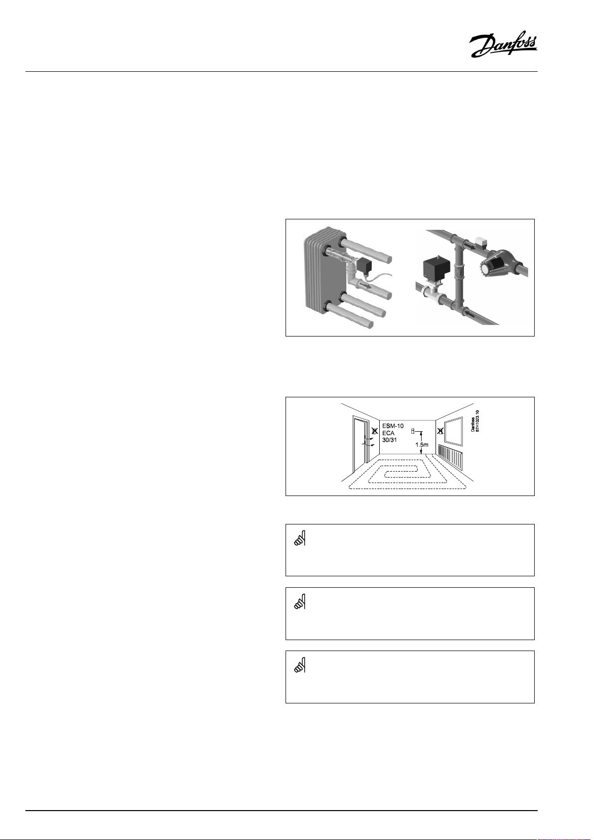
Roomtemperaturesensor
(ESM-10,ECA30/31RemoteControlUnit)
Placetheroomsensorintheroomwherethetemperatureistobe
controlled.Donotplaceitonoutsidewallsorclosetoradiators,
windowsordoors.
Boilertemperaturesensor(ESMU,ESM-11orESMC)
Placethesensoraccordingtotheboilermanufacturer’s
specification.
Airducttemperaturesensor(ESMB-12orESMUtypes)
Placethesensorsothatitmeasuresarepresentativetemperature.
DHWtemperaturesensor(ESMUorESMB-12)
PlacetheDHWtemperaturesensoraccordingtothemanufacturer’s
specification.
Slabtemperaturesensor(ESMB-12)
Placethesensorinaprotectiontubeintheslab.
ESM-11:Donotmovethesensorafterithasbeenfastenedinorderto
avoiddamagetothesensorelement.
ESM-11,ESMCandESMB-12:Useheatconductingpasteforquick
measurementofthetemperature.
ESMUandESMB-12:Usingasensorpockettoprotectthesensorwill,
however,resultinaslowertemperaturemeasurement.
20|©Danfoss|2021.02
AQ000086479358en-010501
Page 21
OperatingGuideECLComfort210/296/310,applicationA237/A337
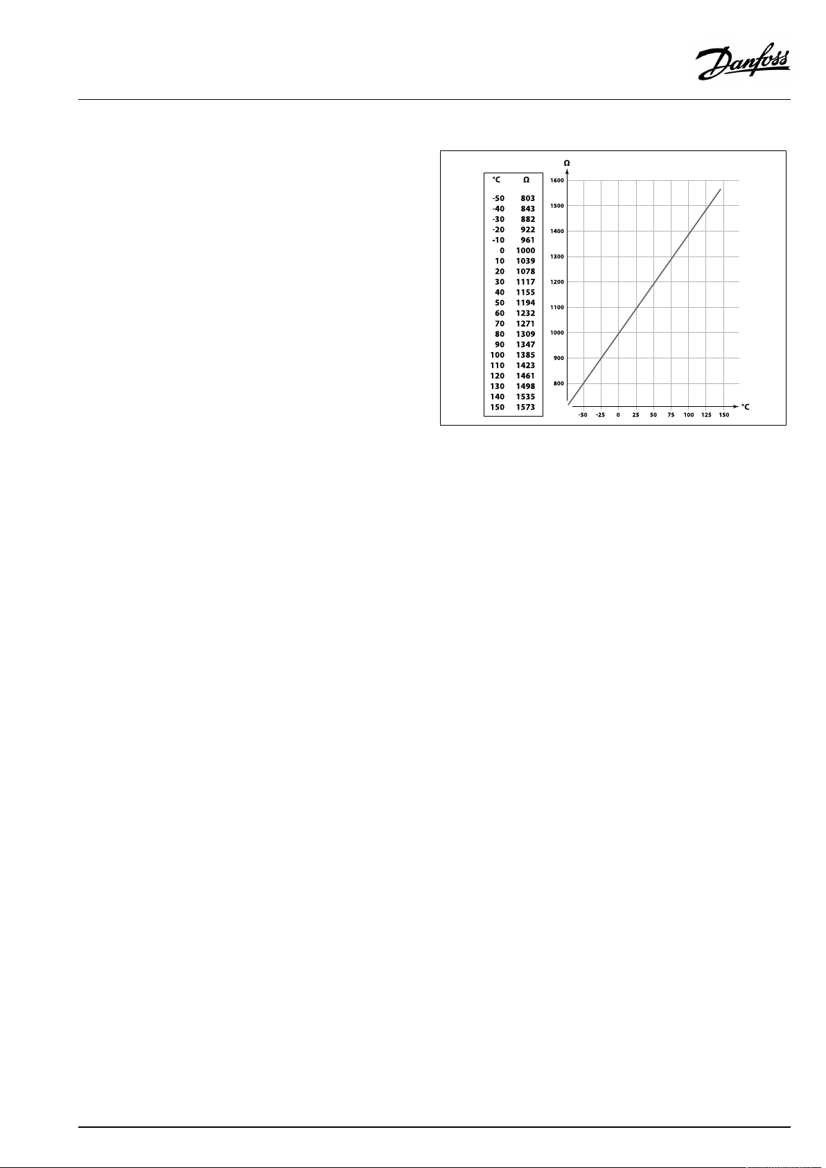
Pt1000temperaturesensor(IEC751B,1000Ω/0°C)
Relationshipbetweentemperatureandohmicvalue:
AQ000086479358en-010501
©Danfoss|2021.02|21
Page 22
OperatingGuideECLComfort210/296/310,applicationA237/A337
2.5Electricalconnections
2.5.1Electricalconnections230Va.c.
Warning
ElectricconductorsonPCB(PrintedCircuitBoard)forsupplyvoltage,
relaycontactsandtriacoutputsdonothavemutualsafetydistanceof
minimum6mm.Theoutputsarenotallowedtobeusedasgalvanic
separated(voltfree)outputs.
Ifagalvanicseparatedoutputisneeded,anauxiliaryrelayis
recommended.
24Voltcontrolledunits,forexampleactuators,aretobecontrolledby
meansofECLComfort310,24Voltversion.
SafetyNote
Necessaryassembly,start-up,andmaintenanceworkmustbe
performedbyqualifiedandauthorizedpersonnelonly.
Locallegislationsmustberespected.Thiscomprisesalsocablesize
andisolation(reinforcedtype).
AfusefortheECLComfortinstallationismax.10Atypically.
TheambienttemperaturerangefortheECLComfortinoperationis
0-55°C.Exceedingthistemperaturerangecanresultinmalfunctions.
Installationmustbeavoidedifthereisariskforcondensation(dew).
22|©Danfoss|2021.02
AQ000086479358en-010501
Page 23
OperatingGuideECLComfort210/296/310,applicationA237/A337
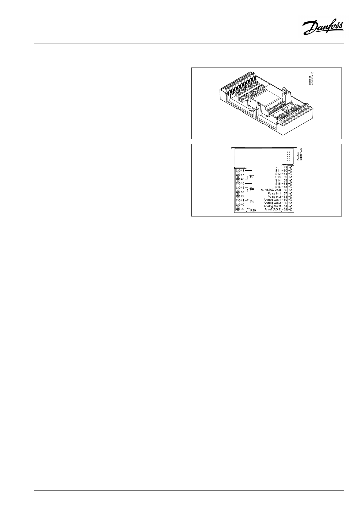
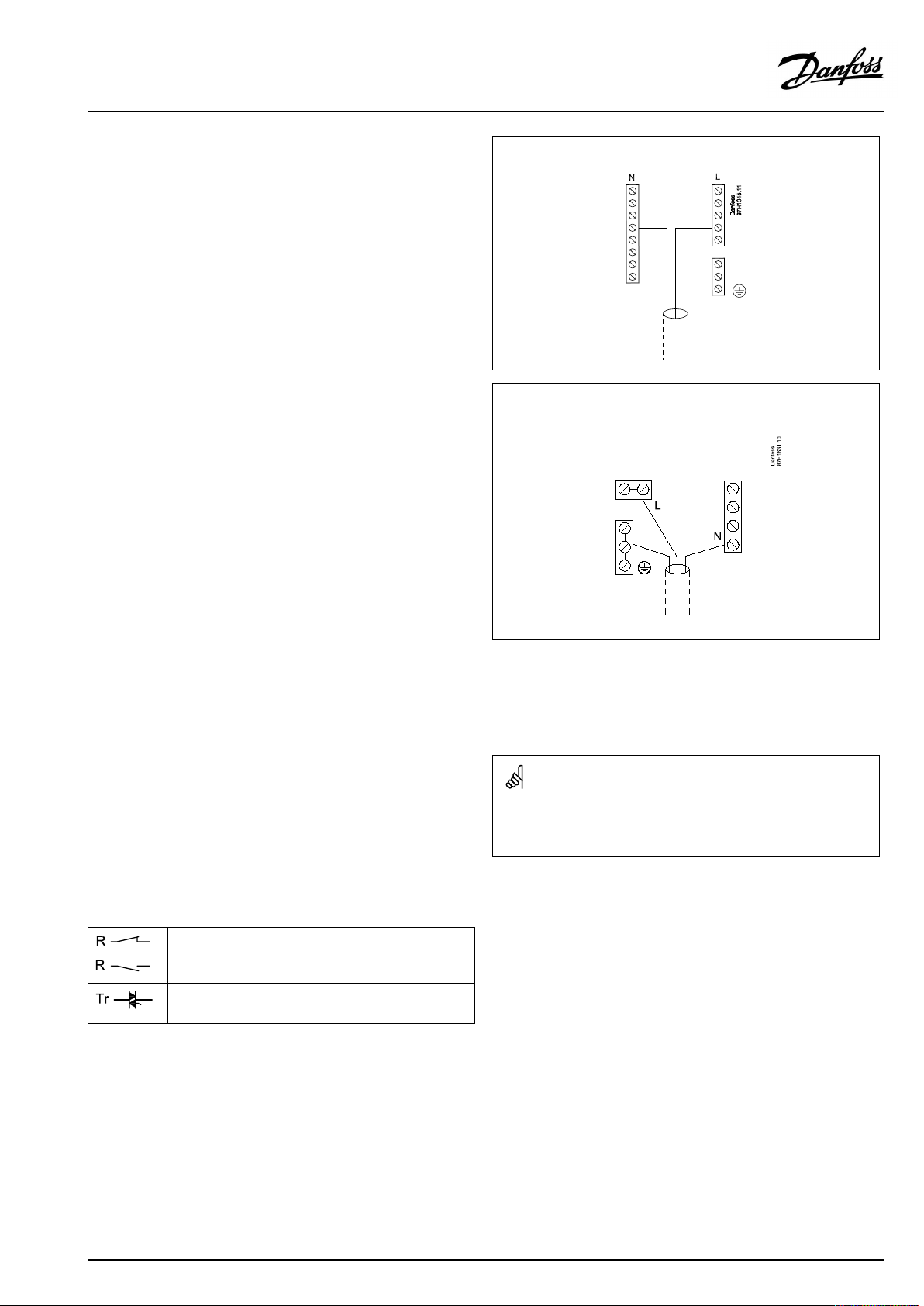
Thecommongroundterminalisusedforconnectionofrelevant
components(pumps,motorizedcontrolvalves).
ECL210/310
ECL296
SeealsotheInstallationGuide(deliveredwiththeapplicationkey)
forapplicationspecificconnections.
Maximumloadratings:
Relayterminals
4(2)A/230Va.c.
(4Aforohmicload,2Afor
inductiveload)
Triac(=electronic
0,2A/230Va.c.
relay)terminals
Wirecrosssection:0.5-1.5mm²
Incorrectconnectioncandamagetheelectronicoutputs.
Max.2x1.5mm²wirescanbeinsertedintoeachscrewterminal.
AQ000086479358en-010501
©Danfoss|2021.02|23
Page 24
OperatingGuideECLComfort210/296/310,applicationA237/A337
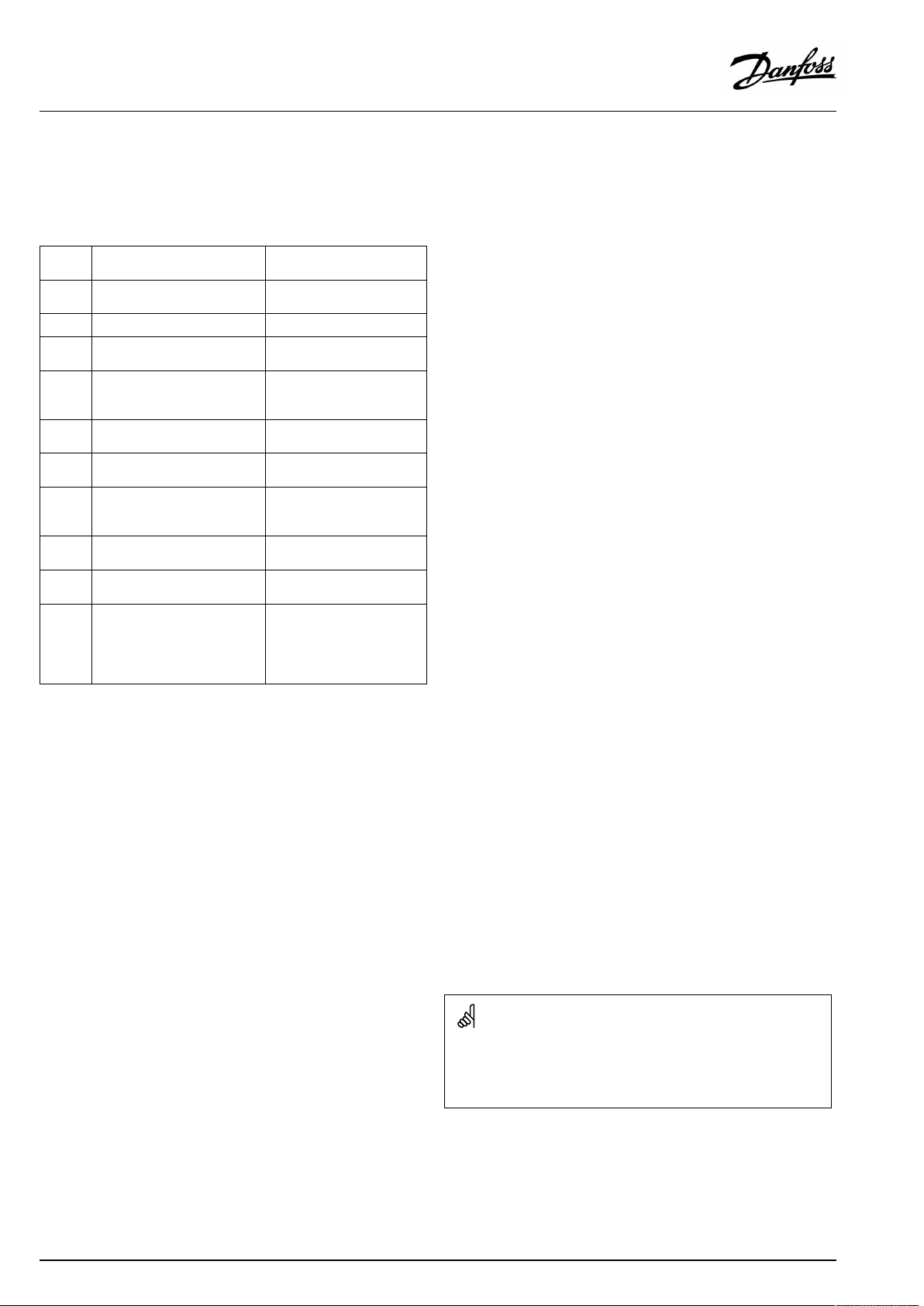
2.5.2Electricalconnections,Pt1000temperaturesensors
SeealsotheInstallationGuide(deliveredwiththeapplicationkey)
forapplicationspecificconnections.
Sensor
S1
Description
Outdoortemperature
sensor*
S2
S3
S4
Roomtemperaturesensor**
Flowtemperaturesensor***
A237.2/A337.2:
DHWchargingtemperature
sensor
S5Returntemperaturesensor
S6
DHWtanktemperature
sensor,upper****
S7
A237.1,A237.2:
Flow/energymeter(pulse
signal)
S8
DHWtanktemperature
sensor,lower
S9
ECL310only:
Notused
S10
ECL310only:
A337.1,A337.2
Voltagesignal(0-10V)for
externalcontrolofdesired
flowtemperature
Recommended
type
ESMT
ESM-10
ESM-11/ESMB/
ESMC/ESMU
ESM-11/ESMB/
ESMC/ESMU
ESM-11/ESMB/
ESMC/ESMU
ESMB/
ESMU
ESMB/
ESMU
*
Iftheoutdoortemperaturesensorisnotconnectedorthe
cableisshort-circuited,thecontrollerassumesthatthe
outdoortemperatureis0(zero)°C.
**
Onlyforroomtemperaturesensorconnection.Theroom
temperaturesignalcanalternativelybeavailablefroma
RemoteControlUnit(ECA30/31).See'Electricalconnections,
ECA30/31'.
***
Theflowtemperaturesensormustalwaysbeconnected
inordertohavethedesiredfunctionality.Ifthesensoris
notconnectedorthecableisshort-circuited,themotorized
controlvalvecloses(safetyfunction).
****
Thissensorisusedifonlyonetanktemperaturesensoris
required.
Wirecrosssectionforsensorconnections:Min.0.4mm².
Totalcablelength:Max.200m(allsensorsincl.internalECL485
communicationbus).
Cablelengthsofmorethan200mmaycausenoisesensibility(EMC).
24|©Danfoss|2021.02
AQ000086479358en-010501
Page 25
OperatingGuideECLComfort210/296/310,applicationA237/A337
A337.1/A337.2:
Connectionofvoltagesignal(0–10V)forexternalcontrolof
desiredflowtemperature
Connectionofflow/energymeterwithpulsesignal
SeetheInstallationGuide(deliveredwiththeapplicationkey).
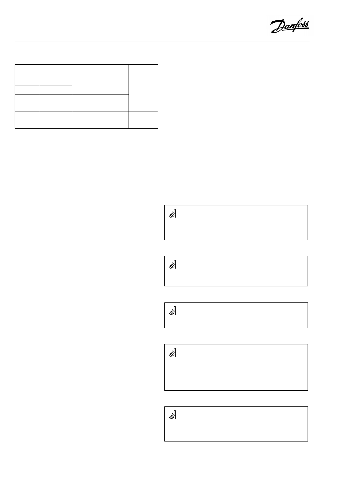
Theoutputoftheflow/energymetercanbeequippedwithan
externalpull-upresistorifaninternalpull-upresistorisnotpresent.
Connectionofswitchforexternaloverride
Pulsebasedsignalforflow/power ,appliedtoinputS7
Formonitoring:
Frequencyrangeis0.01-200Hz
Forlimitation:
Minimumfrequencyisrecommendedtobe1Hzinordertohavea
stablecontrol.Furthermore,thepulsesmustappearregularly.
Wirecrosssectionforsensorconnections:Min.0.4mm².
Totalcablelength:Max.200m(allsensorsincl.internalECL485
communicationbus).
Cablelengthsofmorethan200mmaycausenoisesensibility(EMC).
AQ000086479358en-010501
©Danfoss|2021.02|25
Page 26
OperatingGuideECLComfort210/296/310,applicationA237/A337
2.5.3Electricalconnections,ECA30/31
Terminal
ECL
Terminal
ECA30/31
30
31
4
1
322
333
4
5
*
Afteranexternalroomtemperaturesensorhasbeenconnected,
Description
Twistedpair
Twistedpair
Ext.roomtemperature
sensor*
Type
(recomm.)
Cable2x
twistedpair
ESM-10
ECA30/31mustberepowered.
ThecommunicationtotheECA30/31mustbesetupintheECL
Comfortcontrollerin'ECAaddr.'
TheECA30/31mustbesetupaccordingly.
AfterapplicationsetuptheECA30/31isreadyafter2–5min.A
progressbarintheECA30/31isdisplayed.
Iftheactualapplicationcontainstwoheatingcircuits,itispossible
toconnectanECA30/31toeachcircuit.Theelectricalconnections
aredoneinparallel.
Max.2ECA30/31canbeconnectedtoanECLComfort310controller
ortoECLComfort210/296/310controllersinamaster-slavesystem.
SetupproceduresforECA30/31:Seesection‘Miscellaneous’ .
ECAinformationmessage:
‘Applicationreq.newerECA’:
Thesoftware(firmware)ofyourECAdoesnotcomplywiththe
software(firmware)ofyourECLComfortcontroller.Pleasecontact
yourDanfosssalesoffice.
Someapplicationsdonotcontainfunctionsrelatedtoactualroom
temperature.TheconnectedECA30/31willonlyfunctionasremote
control.
26|©Danfoss|2021.02
AQ000086479358en-010501
Page 27

OperatingGuideECLComfort210/296/310,applicationA237/A337
Totalcablelength:Max.200m(allsensorsincl.internalECL485
communicationbus).
Cablelengthsofmorethan200mmaycausenoisesensibility(EMC).
AQ000086479358en-010501
©Danfoss|2021.02|27
Page 28
OperatingGuideECLComfort210/296/310,applicationA237/A337
2.5.4Electricalconnections,master/slavesystems
Thecontrollercanbeusedasmasterorslaveinmaster/slave
systemsviatheinternalECL485communicationbus(2xtwisted
paircable).
TheECL485communicationbusisnotcompatiblewiththeECL
businECLComfort110,200,300and301!
Terminal
Description
Type
(recomm.)
30
Commonterminal
+12V*,ECL485communicationbus
31
*OnlyforECA30/31andmaster/
slavecommunication
32
B,ECL485communicationbus
33
A,ECL485communicationbus
Cable2x
twistedpair
ECL485buscable
MaximumrecommendedlengthoftheECL485busiscalculatedlike
this:
Subtract"TotallengthofallinputcablesofallECLcontrollersinthe
master-slavesystem"from200m.
Simpleexamplefortotallengthofallinputcables,3xECL:
1xECL
3xECL
3xECLReturntemp.sensor:
3xECLRoomtemp.sensor:
Total:
Outdoortemp.sensor:
Flowtemp.sensor:
15m
18m
18m
30m
81m
2.5.5Electricalconnections,communication
Electricalconnections,Modbus
ECLComfort210:Non-galvanicisolatedModbusconnections
ECLComfort296:GalvanicisolatedModbusconnections
ECLComfort310:GalvanicisolatedModbusconnections
MaximumrecommendedlengthoftheECL485bus:
200-81m=119m
28|©Danfoss|2021.02
AQ000086479358en-010501
Page 29

OperatingGuideECLComfort210/296/310,applicationA237/A337
2.5.6Electricalconnections,communication
Electricalconnections,M-bus
ECLComfort210:Notimplemented
ECLComfort296:Onboard,non-galvanicisolated.Max.cable
length50m.
ECLComfort310:Onboard,non-galvanicisolated.Max.cable
length50m.
AQ000086479358en-010501
©Danfoss|2021.02|29
Page 30
OperatingGuideECLComfort210/296/310,applicationA237/A337
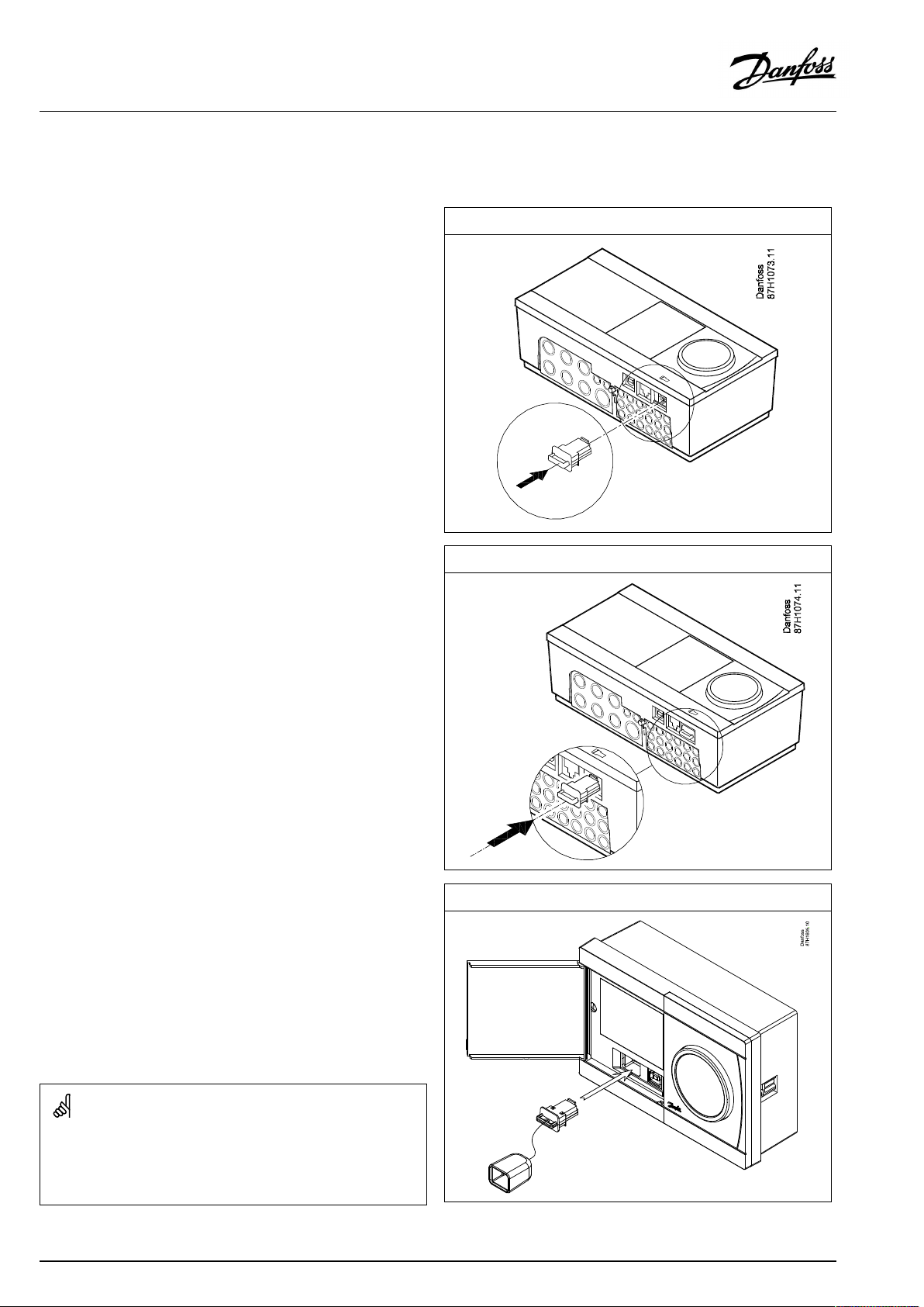
2.6InsertingtheECLApplicationKey
2.6.1InsertingtheECLApplicationKey
TheECLApplicationKeycontains
•theapplicationanditssubtypes,
•currentlyavailablelanguages,
•factorysettings:e.g.schedules,desiredtemperatures,
limitationvaluesetc.Itisalwayspossibletorecoverthefactory
settings,
•memoryforusersettings:specialuser/systemsettings.
Afterhavingpowered-upthecontroller,differentsituationsmight
beexisting:
1.Thecontrollerisnewfromthefactory,theECLApplicationKey
isnotinserted.
2.Thecontrolleralreadyrunsanapplication.TheECLApplication
Keyisinserted,buttheapplicationneedstobechanged.
3.Acopyofthecontrollerssettingsisneededforconfiguring
anothercontroller.
ECLComfort210/310
ECLComfort210/310
Usersettingsare,amongothers,desiredroomtemperature,desired
DHWtemperature,schedules,heatcurve,limitationvaluesetc.
Systemsettingsare,amongothers,communicationset-up,display
brightnessetc.
30|©Danfoss|2021.02
ECLComfort296
AQ000086479358en-010501
Page 31

OperatingGuideECLComfort210/296/310,applicationA237/A337
Automaticupdateofcontrollersoftware(firmware):
Thesoftwareofthecontrollerisupdatedautomaticallywhenthekey
isinserted(asofcontrollerversion1.11(ECL210/310)andversion
1.58(ECL296)).Thefollowinganimationwillbeshownwhenthe
softwareisbeingupdated:
Progressbar
Duringupdate:
•DonotremovetheKEY
Ifthekeyisremovedbeforethehour-glassisshown,youhave
tostartafresh.
•Donotdisconnectthepower
Ifthepowerisinterruptedwhenthehour-glassisshown,the
controllerwillnotwork.
•Manualupdateofcontrollersoftware(firmware):
Seethesection"Automatic/manualupdateoffirmware"
The“Keyoverview”doesnotinform—throughECA30/31—about
thesubtypesoftheapplicationkey.
Keyinserted/notinserted,description:
ECLComfort210/310,controllerversionslowerthan1.36:
-
Takeouttheapplicationkey;for20minutes
settingscanbechanged.
-
Powerupthecontrollerwithoutthe
applicationkeyinserted;for20minutes
settingscanbechanged.
ECLComfort210/310,controllerversions1.36andup:
-
Takeouttheapplicationkey;for20minutes
settingscanbechanged.
-
Powerupthecontrollerwithoutthe
applicationkeyinserted;settingscannotbe
changed.
ECLComfort296,controllerversions1.58andup:
-
Takeouttheapplicationkey;for20minutes
settingscanbechanged.
-
Powerupthecontrollerwithoutthe
applicationkeyinserted;settingscannotbe
changed.
AQ000086479358en-010501
©Danfoss|2021.02|31
Page 32

OperatingGuideECLComfort210/296/310,applicationA237/A337
ApplicationKey:Situation1
Thecontrollerisnewfromthefactory,theECLApplicationKey
isnotinserted.
AnanimationfortheECLApplicationKeyinsertionisdisplayed.
InserttheApplicationKey.
ApplicationKeynameandVersionisindicated(example:A266
Ver.1.03).
IftheECLApplicationKeyisnotsuitableforthecontroller,a"cross"
isdisplayedovertheECLApplicationKey-symbol.
Action:Purpose:
Selectlanguage
Confirm
Selectapplication(subtype)
Somekeyshaveonlyoneapplication.
Confirmwith‘Yes’
Set'Time&Date'
Turnandpushthedialtoselectand
change'Hours' ,'Minutes','Date',
'Month'and'Year' .
Choose''Next'
Confirmwith‘Yes’
Goto‘Aut.daylight’
Choosewhether‘ Aut.daylight´*
shouldbeactiveornot
*‘Aut.daylight’istheautomaticchangeoverbetweensummer
andwintertime.
DependingonthecontentsoftheECLApplicationKey,procedure
AorBistakingplace:
A
TheECLApplicationkeycontainsfactorysettings:
Thecontrollerreads/transfersdatafromtheECLApplicationKey
toECLcontroller.
Examples:
YESorNO
Theapplicationisinstalled,andthecontrollerresetsandstartsup.
B
TheECLApplicationkeycontainschangedsystemsettings:
Pushthedialrepeatedly.
’NO’:
’YES*:
Ifthekeycontainsusersettings:
Pushthedialrepeatedly.
‘NO:
‘YES*:
*If‘YES’cannotbechosen,theECLApplicationKeydoesnot
containanyspecialsettings.
Choose‘Startcopying’andconfirmwith'Yes'.
32|©Danfoss|2021.02
OnlyfactorysettingsfromtheECLApplicationKeywill
becopiedtothecontroller.
Specialsystemsettings(differingfromthefactory
settings)willbecopiedtothecontroller.
OnlyfactorysettingsfromtheECLApplicationKeywill
becopiedtothecontroller.
Specialusersettings(differingfromthefactorysettings)
willbecopiedtothecontroller.
AQ000086479358en-010501
Page 33

OperatingGuideECLComfort210/296/310,applicationA237/A337
(Example):
The"i"intheupperrightcornerindicatesthat-besidesthefactory
settings-thesubtypealsocontainsspecialuser/systemssettings.
ApplicationKey:Situation2
Thecontrolleralreadyrunsanapplication.TheECLApplication
Keyisinserted,buttheapplicationneedstobechanged.
TochangetoanotherapplicationontheECLApplicationKey,the
currentapplicationinthecontrollermustbeerased(deleted).
BeawarethattheApplicationKeymustbeinserted.
Action:Purpose:
Choose‘MENU’inanycircuit
Confirm
Choosethecircuitselectoratthetop
rightcornerinthedisplay
Confirm
Choose‘Commoncontrollersettings’
Confirm
Choose‘Keyfunctions’
Confirm
Choose‘Eraseapplication’
Confirmwith‘Yes’
Thecontrollerresetsandisreadytobeconfigured.
Followtheproceduredescribedinsituation1.
Examples:
AQ000086479358en-010501
©Danfoss|2021.02|33
Page 34

OperatingGuideECLComfort210/296/310,applicationA237/A337
ApplicationKey:Situation3
Acopyofthecontrollerssettingsisneededforconfiguring
anothercontroller.
Thisfunctionisused
•forsaving(backup)ofspecialuserandsystemsettings
•whenanotherECLComfortcontrollerofthesametype(210,
296or310)mustbeconfiguredwiththesameapplicationbut
user/systemsettingsdifferfromthefactorysettings.
HowtocopytoanotherECLComfortcontroller:
Action:Purpose:
Choose‘MENU’
Confirm
Choosethecircuitselectoratthetop
rightcornerinthedisplay
Confirm
Choose'Commoncontrollersettings'
Confirm
Goto‘Keyfunctions’
Confirm
Choose‘Copy’
Confirm
Choose‘To’ .
‘ECL’or‘KEY’willbeindicated.Choose
’ECL’orKEY’
Pushthedialrepeatedlytochoose
copydirection
Choose‘Systemsettings’or‘User
settings’
Pushthedialrepeatedlytochoose
‘Yes’or‘No’in‘Copy’ .Pushtoconfirm.
Choose‘Startcopying’
TheApplicationKeyorthecontroller
isupdatedwithspecialsystemoruser
settings.
Examples:
*
’ECL’or‘KEY’ .
**
‘NO’or‘YES’
*
‘ECL’:
‘KEY’:
**
‘NO’:
‘YES’:
34|©Danfoss|2021.02
DatawillbecopiedfromtheApplicationKeytothe
ECLController.
DatawillbecopiedfromtheECLControllertothe
ApplicationKey.
ThesettingsfromtheECLcontrollerwillnotbecopied
totheApplicationKeyortotheECLComfortcontroller.
Specialsettings(differingfromthefactorysettings)will
becopiedtotheApplicationKeyortotheECLComfort
controller.IfYEScannotbechosen,therearenospecial
settingstobecopied.
AQ000086479358en-010501
Page 35

OperatingGuideECLComfort210/296/310,applicationA237/A337
Language
Atapplicationupload,alanguagemustbeselected.*
IfanotherlanguagethanEnglishisselected,theselectedlanguage
ANDEnglishwillbeuploadedintotheECLcontroller.
ThismakesserviceeasyforEnglishspeakingservicepeople,just
becausetheEnglishlanguagemenuscanbevisiblebychanging
theactualsetlanguageintoEnglish.
(Navigation:MENU>Commoncontroller>System>Language)
Iftheuploadedlanguageisnotsuitable,theapplicationmustbe
erased.UserandSystemsettingscanbesavedontheapplication
keybeforeerasing.
Afternewuploadwithpreferredlanguage,theexistingUserand
Systemsettingscanbeuploaded.
*)
(ECLComfort310,24Volt)Iflanguagecannotbeselected,the
powersupplyisnota.c.(alternatingcurrent).
2.6.2ECLApplicationKey,copyingdata
Generalprinciples
Whenthecontrollerisconnectedandoperating,youcancheck
andadjustallorsomeofthebasicsettings.Thenewsettingscan
bestoredontheKey.
Factorysettingscanalwaysberestored.
HowtoupdatetheECLApplicationKeyaftersettingshave
beenchanged?
AllnewsettingscanbestoredontheECLApplicationKey.
Howtostorefactorysettinginthecontrollerfromthe
ApplicationKey?
PleasereadtheparagraphconcerningApplicationKey,Situation
1:Thecontrollerisnewfromthefactory,theECLApplicationKey
isnotinserted.
HowtostorepersonalsettingsfromthecontrollertotheKey?
PleasereadtheparagraphconcerningApplicationKey,Situation3:
Acopyofthecontrollerssettingsisneededforconfiguringanother
controller
Asamainrule,theECLApplicationKeyshouldalwaysremainin
thecontroller.IftheKeyisremoved,itisnotpossibletochange
settings.
Makeanoteofnewsettingsinthe'Settingsoverview'table.
DonotremovetheECLApplicationKeywhilecopying.Thedataon
theECLApplicationKeycanbedamaged!
ItispossibletocopysettingsfromoneECLComfortcontrollerto
anothercontrollerprovidedthatthetwocontrollersarefromthesame
series(210or310).
Furthermore,whentheECLComfortcontrollerhasbeenuploaded
withanapplicationkey,minimumversion2.44,itispossibletoupload
personalsettingsfromapplicationkeys,minimumversion2.14.
AQ000086479358en-010501
©Danfoss|2021.02|35
Page 36

OperatingGuideECLComfort210/296/310,applicationA237/A337
The“Keyoverview”doesnotinform—throughECA30/31—about
thesubtypesoftheapplicationkey.
Keyinserted/notinserted,description:
ECLComfort210/310,controllerversionslowerthan1.36:
-
Takeouttheapplicationkey;for20minutes
settingscanbechanged.
-
Powerupthecontrollerwithoutthe
applicationkeyinserted;for20minutes
settingscanbechanged.
ECLComfort210/310,controllerversions1.36andup:
-
Takeouttheapplicationkey;for20minutes
settingscanbechanged.
-
Powerupthecontrollerwithoutthe
applicationkeyinserted;settingscannotbe
changed.
ECLComfort296,controllerversions1.58andup:
-
Takeouttheapplicationkey;for20minutes
settingscanbechanged.
-
Powerupthecontrollerwithoutthe
applicationkeyinserted;settingscannotbe
changed.
36|©Danfoss|2021.02
AQ000086479358en-010501
Page 37

OperatingGuideECLComfort210/296/310,applicationA237/A337
2.7Checklist
IstheECLComfortcontrollerreadyforuse?
Makesurethatthecorrectpowersupplyisconnectedtoterminals9and10(230Vor24V).
Makesurethecorrectphaseconditionsareconnected:
230V:Live=terminal9andNeutral=terminal10
24V:SP=terminal9andSN=terminal10
Checkthattherequiredcontrolledcomponents(actuator,pumpetc.)areconnectedtothecorrectterminals.
Checkthatallsensors/signalsareconnectedtothecorrectterminals(see'Electricalconnections').
Mountthecontrollerandswitchonthepower.
IstheECLApplicationKeyinserted(see'InsertingtheApplicationKey').
DoestheECLComfortcontrollercontainanexistingapplication(see'InsertingtheApplicationKey').
Isthecorrectlanguagechosen(see'Language'in'Commoncontrollersettings').
Isthetime&datesetcorrectly(see'Time&Date'in'Commoncontrollersettings').
Istherightapplicationchosen(see'Identifyingthesystemtype').
Checkthatallsettingsinthecontroller(see'Settingsoverview')aresetorthatthefactorysettingscomplywithyour
requirements.
Choosemanualoperation(see'Manualcontrol').Checkthatvalvesopenandclose,andthatrequiredcontrolled
components(pumpetc.)startandstopwhenoperatedmanually.
Checkthatthetemperatures/signalsshowninthedisplaymatchtheactualconnectedcomponents.
Havingcompletedthemanualoperationcheck,choosecontrollermode(scheduled,comfort,savingorfrostprotection).
AQ000086479358en-010501
©Danfoss|2021.02|37
Page 38

OperatingGuideECLComfort210/296/310,applicationA237/A337
2.8Navigation,ECLApplicationKeyA237/A337
Navigation,applicationA237.1/A337.1(*A237.1only,**A337.1only)
Home
IDno.
MENU
ScheduleSelectableSelectable
Schedulecirc.PSelectable
Settings
Flowtemperature(circuit1)
Tanktemperature(circuit2)
Roomlimit
Returnlimit
Flow/powerlimitActualActual
Optimization
Controlpar.
11178
11177
11004
11182
11183
11015
11031
11032
11033
11034
11035
11036
11037
11085
11028
11119
11117
11118
11116
11112
11113
11109
11115
11114
11011
11012
11013
11014
11026
11020
11021
11179
11043
11174
11184
11185
11186
11187
11189
11024
Heating,circuit1DHW,circuit2
Function
Heatcurve12193Chargedifference
Temp.max.
Temp.min.
DesiredT
Ext.desiredT**
Infl.—max.
Infl.—min.
Adapt.time
HighToutX1
LowlimitY1
LowToutX2
HighlimitY2
Infl.-max.
Infl.-min.
Adapt.time
Priority
Con.T,ret.Tlim.
Actuallimit
HighToutX1
LowlimitY1
LowToutX2
HighlimitY2
Adapt.time
Filterconstant
Inputtype
Units
Pulse*
Autosaving
Boost
Ramp
Optimizer
Pre-stop
Basedon
Totalstop
Summer,cut-out
Paralleloperation
Motorpr.
Xp
Tn
Mrun
Nz
Min.act.time
Actuator
IDno.
12195
12194
12152
12030
12111
Function
Startdifference
Stopdifference
Max.chargeT
Limit
Limit
38|©Danfoss|2021.02
AQ000086479358en-010501
Page 39

OperatingGuideECLComfort210/296/310,applicationA237/A337
Navigation,applicationA237.1/A337.1,continued(*A337.1only)
Home
IDno.
MENU
Settings
HolidaySelectableSelectable
Alarm
Influenceoverview
Application
Heatcut-out
Anti-bacteriaSelectable
Temp.monitor.
AlarmoverviewSelectable
Des.flowT(circuit1)
Des.DHWT(circuit2)
11010
11017
11050
11500
11022
11023
11052
11077
11078
11040
11093
11141
11142
11393
11392
11179
11395
11397
11396
11398
11399
11147
11148
11149
11150
Heating,circuit1DHW,circuit2
Function
ECAaddr.
Demandoffset
Pdemand
SenddesiredT
Pexercise
Mexercise
DHWpriority
PfrostT
PheatT
Ppost-run
Frostpr.T
Ext.input
Ext.mode
Sum.start,day
Sum.start,month
Summer,cut-out
Summer,filter
Winterstart,day
Winterstart,month
Winter,cut-out
Winter,filter
Upperdifference
Lowerdifference
Delay
Lowesttemp.
Returnlim.Holiday
Roomlim.Ext.override
Flow/powerlim.Anti-bacteria
HolidaySCADAoverride
Ext.override
ECAoverride
Boost
Ramp
Slave,demand
Heatingcut-out
DHWpriority
DHWinfluence
SCADAoffset
Ext.desiredT*
IDno.
12051
12053
12055
12044
12045
12041
12059
12500
12076
12093
12141
12142
Function
Ch.-o.valve/P
Tank,sec./prim.
Circ.Ppriority
Max.DHWtime
DHWdeact.time
DHWPpost-run
Pchargedelay
SenddesiredT
Circ.PfrostT
Frostpr.T
Ext.input
Ext.mode
AQ000086479358en-010501
©Danfoss|2021.02|39
Page 40

OperatingGuideECLComfort210/296/310,applicationA237/A337
Navigation,applicationA237.1/A337.1,Commoncontrollersettings(*A337.1only)
Home
MENU
Time&Date
HolidaySelectable
Inputoverview
Log(sensors)
Outputoverride
Keyfunctions
SystemECLversion
OutdoorTLogtoday
RoomT&desiredLogyesterday
FlowT&desiredLog2days
ReturnT&limitLog4days
TankTup.&des.
TankTup.&low.
NewapplicationEraseapplication
Application
FactorysettingSystemsettings
Copy
Keyoverview
Extension
Ethernet
Portalconfig
M-busconfig
EnergyMeters
RawinputoverviewS1...S10
Alarm
Display
Communication
Language
IDno.
60058
60059
38
39
2048
2150
2151
2050
Commoncontrollersettings
Function
Selectable
OutdoorT
Outdooracc.T
RoomT
FlowT
ReturnT
TankupperT
TanklowerT
Ext.desiredT*
M1,P1,P2,P3,A1
Usersettings
Gotofactory
To
Systemsettings
Usersettings
Startcopying
Codeno.
Hardware
Software
Buildno.
Serialno.
MAC
Productionweek
Selectable
Selectable
Backlight
Contrast
Modbusaddr.
Baud
ECL485addr.
Servicepin
Ext.reset
Language
40|©Danfoss|2021.02
AQ000086479358en-010501
Page 41

OperatingGuideECLComfort210/296/310,applicationA237/A337
Navigation,applicationA237.2/A337.2(*A237.2only,**A337.2only)
Home
IDno.
ScheduleSelectableSelectable
Schedulecirc.PSelectable
Settings
Flowtemperature(circuit1)
Tanktemperature(circuit2)
Roomlimit
Returnlimit
Flow/powerlimitActualActual
Optimization
Controlpar.
11178
11177
11004
11182
11183
11015
11031
11032
11033
11034
11035
11036
11037
11085
11028
11119
11117
11118
11116
11112
11113
11109
11115
11114
11011
11012
11013
11014
11026
11020
11021
11179
11043
11174
11184
11185
11186
11187
11189
11024
Heating,circuit1DHW,circuit2
Function
Heatcurve12193Chargedifference
Temp.max.
Temp.min.
DesiredT
Ext.desiredT**
Infl.—max.
Infl.—min.
Adapt.time
HighToutX1
LowlimitY1
LowToutX2
HighlimitY2
Infl.-max.
Infl.-min.
Adapt.time
Priority
Con.T,ret.Tlim.
Actuallimit
HighToutX1
LowlimitY1
LowToutX2
HighlimitY2
Adapt.time
Filterconstant
Inputtype
Units
Pulse*
Autosaving
Boost
Ramp
Optimizer
Pre-stop
Basedon
Totalstop
Summer,cut-out
Paralleloperation
Motorpr.
Xp
Tn
Mrun
Nz
Min.act.time
Actuator
IDno.
12195
12194
12152
12068
12030
12111
Function
Startdifference
Stopdifference
Max.chargeT
FlowTadapttime
Limit
Limit
AQ000086479358en-010501
©Danfoss|2021.02|41
Page 42

OperatingGuideECLComfort210/296/310,applicationA237/A337
Navigation,applicationA237.2/A337.2,continued(*A337.2only)
Home
IDno.
MENU
Settings
HolidaySelectableSelectable
Alarm
Influenceoverview
Application
Heatcut-out
Anti-bacteriaSelectable
Temp.monitor.
AlarmoverviewSelectable
Des.flowT(circuit1)
Des.DHWT(circuit2)
11010
11017
11050
11500
11022
11023
11052
11077
11078
11040
11093
11141
11142
11393
11392
11179
11395
11397
11396
11398
11399
11147
11148
11149
11150
Heating,circuit1DHW,circuit2
Function
ECAaddr.
Demandoffset
Pdemand
SenddesiredT
Pexercise
Mexercise
DHWpriority
PfrostT
PheatT
Ppost-run
Frostpr.T
Ext.input
Ext.mode
Sum.start,day
Sum.start,month
Summer,cut-out
Summer,filter
Winterstart,day
Winterstart,month
Winter,cut-out
Winter,filter
Upperdifference
Lowerdifference
Delay
Lowesttemp.
Returnlim.Holiday
Roomlim.Ext.override
Flow/powerlim.Anti-bacteria
HolidaySCADAoverride
Ext.override
ECAoverride
Boost
Ramp
Slave,demand
Heatingcut-out
DHWpriority
DHWinfluence
SCADAoffset
Ext.desiredT*
IDno.
12051
12055
12044
12045
12041
12059
12042
12500
12076
12093
12141
12142
Function
Ch.-o.valve/P
Circ.Ppriority
Max.DHWtime
DHWdeact.time
DHWPpost-run
Pchargedelay
Char.Ppost-run
SenddesiredT
Circ.PfrostT
Frostpr.T
Ext.input
Ext.mode
42|©Danfoss|2021.02
AQ000086479358en-010501
Page 43

OperatingGuideECLComfort210/296/310,applicationA237/A337
Navigation,applicationA237.2/A337.2,Commoncontrollersettings(*A337.2only)
Home
MENU
Time&Date
HolidaySelectable
Inputoverview
Log(sensors)
Outputoverride
Keyfunctions
SystemECLversion
OutdoorTLogtoday
RoomT&desiredLogyesterday
FlowT&desiredLog2days
ReturnT&limitLog4days
TankTup.&des.
TankTup.&low.
ChargeT
NewapplicationEraseapplication
Application
FactorysettingSystemsettings
Copy
Keyoverview
Extension
Ethernet
Portalconfig
M-busconfig
EnergyMeters
RawinputoverviewS1...S10
Alarm
Display
Communication
Language
IDno.
60058
60059
38
39
2048
2150
2151
2050
Commoncontrollersettings
Function
Selectable
OutdoorT
Outdooracc.T
RoomT
FlowT
ChargeT
ReturnT
TankupperT
TanklowerT
Ext.desiredT*
M1,P1,P2,P3,P4,A1*
Usersettings
Gotofactory
To
Systemsettings
Usersettings
Startcopying
Codeno.
Hardware
Software
Buildno.
Serialno.
MAC
Productionweek
Selectable
Selectable
Backlight
Contrast
Modbusaddr.
Baud
ECL485addr.
Servicepin
Ext.reset
Language
AQ000086479358en-010501
©Danfoss|2021.02|43
Page 44

OperatingGuideECLComfort210/296/310,applicationA237/A337
3.0Dailyuse
3.1Howtonavigate
Younavigateinthecontrollerbyturningthedialleftorrightto
thedesiredposition().
Thedialhasabuilt-inaccellerator.Thefasteryouturnthedial,the
fasteritreachesthelimitsofanywidesettingrange.
Thepositionindicatorinthedisplay(
youare.
Pushthedialtoconfirmyourchoices().
Thedisplayexamplesarefromatwo-circuitapplication:One
heatingcircuit()andonedomestichot-water(DHW)circuit().
Theexamplesmightdifferfromyourapplication.
)willalwaysshowyouwhere
ExampleshowsECL210/310
Heatingcircuit():DHWcircuit();
Somegeneralsettingswhichapplytotheentirecontrollerare
locatedinaspecificpartofthecontroller.
Toenter‘Commoncontrollersettings’:
Action:Purpose:
Choose‘MENU’inanycircuit
Confirm
Choosethecircuitselectoratthetop
rightcornerinthedisplay
Confirm
Choose‘Commoncontrollersettings’
Confirm
Examples:
Circuitselector
44|©Danfoss|2021.02
AQ000086479358en-010501
Page 45

OperatingGuideECLComfort210/296/310,applicationA237/A337
3.2Understandingthecontrollerdisplay
ThissectiondescribesthefunctioningeneralfortheECLComfort
210/296/310series.Theshowndisplaysaretypicalandnot
applicationrelated.Theymightdifferfromthedisplaysinyour
application.
Choosingafavoritedisplay
Yourfavoritedisplayisthedisplayyouhavechosenasthedefault
display.Thefavoritedisplaywillgiveyouaquickoverviewofthe
temperaturesorunitsthatyouwanttomonitoringeneral.
Ifthedialhasnotbeenactivatedfor20min.,thecontrollerwill
reverttotheoverviewdisplayyouhavechosenasfavorite.
Toshiftbetweendisplays:Turnthedialuntilyoureachthedisplay
selector(
turntochooseyourfavoriteoverviewdisplay.Pushthedialagain.
)atthebottomrightsideofthedisplay.Pushthedialand
Heatingcircuit
Overviewdisplay1informsabout:
actualoutdoortemperature,controllermode,
actualroomtemperature,desiredroomtemperature.
Overviewdisplay2informsabout:
actualoutdoortemperature,trendinoutdoortemperature,
controllermode,max.andmin.outdoortemperaturessince
midnightaswellasdesiredroomtemperature.
Overviewdisplay3informsabout:
date,actualoutdoortemperature,controllermode,time,desired
roomtemperatureaswellasshowsthecomfortscheduleofthe
currentday.
Overviewdisplay4informsabout:
stateofthecontrolledcomponents,actualflowtemperature,
(desiredflowtemperature),controllermode,returntemperature
(limitationvalue),influenceondesiredflowtemperature.
ThevalueabovetheV2symbolindicates0–100%oftheanalogue
signal(0–10V).
Note:
Anactualflowtemperaturevaluemustbepresent,otherwisethe
circuit'scontrolvalvewillclose.
Overviewdisplay1:Overviewdisplay2:
Overviewdisplay3:Overviewdisplay4:
Exampleofoverviewdisplaywith
Influenceindication:
Example,favoritedisplay1in
A230.3,wheremin.desiredroom
temperatureisindicated(22.7):
Dependentonthechosendisplay,theoverviewdisplaysforthe
heatingcircuitinformyouabout:
•actualoutdoortemperature(-0.5)
•controllermode()
•actualroomtemperature(24.5)
•desiredroomtemperature(20.7°C)
•trendinoutdoortemperature(
)
•min.andmax.outdoortemperaturessincemidnight(
•date(23.02.2010)
•time(7:43)
•comfortscheduleofthecurrentday(0-12-24)
•stateofthecontrolledcomponents(M2,P2)
•actualflowtemperature(49°C),(desiredflowtemperature(31))
•returntemperature(24°C)(limitationtemperature(50))
AQ000086479358en-010501
)
©Danfoss|2021.02|45
Page 46

OperatingGuideECLComfort210/296/310,applicationA237/A337
Thesettingofthedesiredroomtemperatureisimportantevenifa
roomtemperaturesensor/RemoteControlUnitisnotconnected.
Ifthetemperaturevalueisdisplayedas
"--"
thesensorinquestionisnotconnected.
"---"
thesensorconnectionisshort-circuited.
DHWcircuit
Overviewdisplay1informsabout:
actualDHWtemperature,controllermode,desiredDHW
temperatureaswellasthecomfortscheduleofthecurrentday.
Overviewdisplay2informsabout:
stateofthecontrolledcomponents,actualDHWtemperature,
(desiredDHWtemperature),controllermode,returntemperature
(limitationvalue),influenceondesiredDHWtemperature.
Dependentonchosendisplay,theoverviewdisplaysfortheDHW
circuitinformyouabout:
•actualDHWtemperature(50.3)
•controllermode(
)
•desiredDHWtemperature(50°C)
•comfortscheduleofthecurrentday(0-12-24)
•stateofthecontrolledcomponents(M1,P1)
•actualDHWtemperature(50°C),(desiredDHWtemperature(50))
•returntemperature(--°C)(limitationtemperature(30))
Settingthedesiredtemperature
Dependingonthechosencircuitandmode,itispossibletoenter
alldailysettingsdirectlyfromtheoverviewdisplays(seealsothe
nextpageconcerningsymbols).
Overviewdisplay1:Overviewdisplay2:
Exampleofoverviewdisplaywith
Influenceindication:
46|©Danfoss|2021.02
AQ000086479358en-010501
Page 47

OperatingGuideECLComfort210/296/310,applicationA237/A337
Settingthedesiredroomtemperature
Thedesiredroomtemperaturecaneasilybeadjustedinthe
overviewdisplaysfortheheatingcircuit.
Action:Purpose:
Desiredroomtemperature
Confirm
Adjustthedesiredroomtemperature
Confirm
Thisoverviewdisplayinformsaboutoutdoortemperature,actual
roomtemperatureaswellasdesiredroomtemperature.
Thedisplayexampleisforcomfortmode.Ifyouwanttochange
thedesiredroomtemperatureforsavingmode,choosethemode
selectorandselectsaving.
Examples:
20.5
21.0
Thesettingofthedesiredroomtemperatureisimportantevenifa
roomtemperaturesensor/RemoteControlUnitisnotconnected.
SettingthedesiredDHWtemperature
ThedesiredDHWtemperaturecaneasilybeadjustedinthe
overviewdisplaysfortheDHWcircuit.
Action:Purpose:
DesiredDHWtemperature
Confirm
AdjustthedesiredDHWtemperature
Confirm
InadditiontotheinformationaboutdesiredandactualDHW
temperature,thetoday'sscheduleisvisible.
Thedisplayexampleindicatesthatthecontrollerisinscheduled
operationandincomfortmode.
Examples:
50
55
AQ000086479358en-010501
©Danfoss|2021.02|47
Page 48

OperatingGuideECLComfort210/296/310,applicationA237/A337
Settingthedesiredroomtemperature,ECA30/ECA31
Thedesiredroomtemperaturecanbesetexactlyasinthe
controller.However,othersymbolscanbepresentinthedisplay
(pleasesee'Whatdothesymbolsmean?').
WiththeECA30/ECA31youcanoverridethedesiredroom
temperaturesetinthecontrollertemporarilybymeansoftheoverride
functions:
48|©Danfoss|2021.02
AQ000086479358en-010501
Page 49

OperatingGuideECLComfort210/296/310,applicationA237/A337
3.3Ageneraloverview:Whatdothesymbolsmean?
Symbol
Description
Outdoortemp.
Relativehumidityindoor
Roomtemp.
DHWtemp.
Positionindicator
Scheduledmode
Comfortmode
Savingmode
Frostprotectionmode
Manualmode
Standby
Coolingmode
Symbol
Temperature
Mode
Description
Alarm
Letter
Event
Monitoringtemperaturesensor
connection
Displayselector
Max.andmin.value
Trendinoutdoortemperature
Windspeedsensor
Sensornotconnectedornotused
Sensorconnectionshort-circuited
Fixedcomfortday(holiday)
Activeinfluence
Heatingactive(+)
Coolingactive(-)
Activeoutputoverride
Optimizedstartorstoptime
Heating
Cooling
DHW
Commoncontrollersettings
PumpON
PumpOFF
FanON
FanOFF
Actuatoropens
Actuatorcloses
Actuator,analoguecontrol
signal
Pump/fanspeed
DamperON
Circuit
Controlled
component
Numberofheatexchangers
Additionalsymbols,ECA30/31:
Symbol
InECA30/31onlythesymbolsthatarerelevanttotheapplicationin
thecontrolleraredisplayed.
Description
ECARemoteControlUnit
Connectionaddress(master:15,slaves:1-9)
15
Dayoff
Holiday
Relaxing(extendedcomfortperiod)
Goingout(extendedsavingperiod)
DamperOFF
AQ000086479358en-010501
©Danfoss|2021.02|49
Page 50

OperatingGuideECLComfort210/296/310,applicationA237/A337
3.4Monitoringtemperaturesandsystemcomponents
ThissectiondescribesthefunctioningeneralfortheECLComfort
210/296/310series.Theshowndisplaysaretypicalandnot
applicationrelated.Theymightdifferfromthedisplaysinyour
application.
Heatingcircuit
Theoverviewdisplayintheheatingcircuitensuresaquick
overviewoftheactualand(desired)temperaturesaswellasthe
actualstateofthesystemcomponents.
Displayexample:
49°C
(31)
24°C
(50)
DHWcircuit
TheoverviewdisplayintheDHWcircuitensuresaquickoverview
oftheactualand(desired)temperaturesaswellastheactualstate
ofthesystemcomponents.
Displayexample(heatexchanger):
50°C
(50)
(30)
Flowtemperature
Desiredflowtemperature
Returntemperature
Returntemperaturelimitation
Flowtemperature
Desiredflowtemperature
--
Returntemperature:sensornotconnected
Returntemperaturelimitation
Displayexamplewithheatexchanger:
Inputoverview
Anotheroptiontogetaquickoverviewofmeasuredtemperatures
isthe'Inputoverview'whichisvisibleinthecommoncontroller
settings(howtoenterthecommoncontrollersettings,see
‘Introductiontocommoncontrollersettings’ .)
Asthisoverview(seedisplayexample)onlystatesthemeasured
actualtemperatures,itisread-only.
50|©Danfoss|2021.02
AQ000086479358en-010501
Page 51

OperatingGuideECLComfort210/296/310,applicationA237/A337
3.5Influenceoverview
ThissectiondescribesthefunctioningeneralfortheECLComfort
210/296/310series.Theshowndisplaysaretypicalandnot
applicationrelated.Theymightdifferfromthedisplaysinyour
application.
Themenugivesanoverviewoftheinfluencesonthedesired
flowtemperature.Itdiffersfromapplicationtoapplicationwhich
parametersarelisted.Itcanbehelpfulinaservicesituationto
explainunexpectedconditionsortemperaturesamongothers.
Ifthedesiredflowtemperatureisinfluenced(corrected)byoneor
moreparameters,itisindicatedbyasmalllinewitharrow-down,
arrow-upordouble-arrow:
Arrow-down:
Theparameterinquestionreducesthedesiredflowtemperature.
Arrow-up:
Theparameterinquestionincreasesthedesiredflowtemperature.
Double-arrow:
Theparameterinquestioncreatesanoverride(e.g.Holiday).
Straightline:
Noactiveinfluence.
Intheexample,thearrowinthesymbolpointsdownwardsfor
'Roomlim. ' .Thismeansthattheactualroomtemperatureis
higherthanthedesiredroomtemperaturewhichagainresultsina
decreaseofthedesiredflowtemperature.
ExampleofoverviewdisplaywithInfluenceindication:
AQ000086479358en-010501
©Danfoss|2021.02|51
Page 52

OperatingGuideECLComfort210/296/310,applicationA237/A337
3.6Manualcontrol
ThissectiondescribesthefunctioningeneralfortheECLComfort
210/296/310series.Theshowndisplaysaretypicalandnot
applicationrelated.Theymightdifferfromthedisplaysinyour
application.
Itispossibletomanuallycontroltheinstalledcomponents.
Manualcontrolcanonlybeselectedinfavoritedisplaysinwhich
thesymbolsforthecontrolledcomponents(valve,pumpetc.)are
visible.
Action:Purpose:
Choosemodeselector
Confirm
Choosemanualmode
Confirm
Choosepump
Confirm
SwitchONthepump
SwitchOFFthepump.
Confirmpumpmode
Choosemotorizedcontrolvalve
Confirm
Openthevalve
Stopopeningthevalve
Closethevalve
Examples:
ControlledcomponentsCircuitselector
Duringmanualoperation:
•Allcontrolfunctionsaredeactivated
•Outputoverrideisnotpossible
•Frostprotectionisnotactive
Stopclosingthevalve
Confirmvalvemode
Toleavemanualcontrol,usethemodeselectortoselectthe
desiredmode.Pushthedial.
Manualcontrolistypicallyusedwhencommisioningthe
installation.Thecontrolledcomponents,valve,pumpetc.,canbe
controlledforcorrectfunction.
52|©Danfoss|2021.02
Whenmanualcontrolisselectedforonecircuit,itisautomatically
selectedforallcircuits!
AQ000086479358en-010501
Page 53

OperatingGuideECLComfort210/296/310,applicationA237/A337
3.7Schedule
3.7.1Setyourschedule
ThissectiondescribesthescheduleingeneralfortheECLComfort
210/296/310series.Theshowndisplaysaretypicalandnot
applicationrelated.Theymightdifferfromthedisplaysinyour
application.Insomeapplications,however,theremightbemore
thanoneschedule.Additionalschedulescanbefoundin‘Common
controllersettings’ .
Thescheduleconsistsofa7-dayweek:
=
M
Monday
=
T
Tuesday
=
W
Wednesday
=
T
Thursday
=
F
Friday
=
S
Saturday
=
S
Sunday
Theschedulewillday-by-dayshowyouthestartandstoptimesof
yourcomfortperiods(heating/DHWcircuits).
Changingyourschedule:
Action:
Purpose:
Choose'MENU'inanyoftheoverview
displays
Confirm
Confirmthechoice'Schedule'
Choosethedaytochange
Confirm*
GotoStart1
Confirm
Adjustthetime
Confirm
GotoStop1,Start2etc.etc.
Returnto'MENU'
Confirm
Choose'Yes'or'No'in'Save'
Confirm
Examples:
*Severaldayscanbemarked
Thechosenstartandstoptimeswillbevalidforallthechosendays
(inthisexampleThursdayandSaturday).
Youcansetmax.3comfortperiodsaday.Youcandeleteacomfort
periodbysettingstartandstoptimestothesamevalue.
AQ000086479358en-010501
Eachcircuithasitsownschedule.Tochangetoanothercircuit,goto
'Home',turnthedialandchoosethedesiredcircuit.
Thestartandstoptimescanbesetinhalf-hourly(30min.)intervals.
©Danfoss|2021.02|53
Page 54

OperatingGuideECLComfort210/296/310,applicationA237/A337
4.0Settingsoverview
Forfactorysettingsandsettingrange,seeappendix“ParameterIDoverview” .
ParametersindicatedwithanIDno.like"1x607"meanauniversalparameter.xstandsforcircuit/parametergroup.
SettingIDPage
Heatcurve
Ext.desiredT—(ECLComfort310)
Actual(actualfloworpower)
Extendedheatcut-outsetting
Extendedwintercut-outsetting
Day
Starttime
Duration
DesiredT
DesiredT(Desiredflowtemperature)
ECAaddr.(ECAaddress,choiceofRemoteControlUnit)
Autosaving(savingtemp.dependentonoutdoortemp.)
Boost
Ramp(referenceramping)
Optimizer(optimizingtimeconstant)
Adapt.time(adaptiontime)
Demandoffset
Basedon(optimizationbasedonroom/outdoortemp.)
Totalstop
Pexercise(pumpexercise)
Mexercise(valveexercise)
Actuator
Pre-stop(optimizedstoptime)
Con.T,re.Tlim.(Constanttemperaturemode,return
temperaturelimitation)
Limit(returntemp.limitation)
HighToutX1(returntemp.limitation,highlimit,X-axis)
LowlimitY1(returntemp.limitation,lowlimit,Y-axis)
LowToutX2(returntemp.limitation,lowlimit,X-axis)
HighlimitY2(returntemp.limitation,highlimit,Y-axis)
Infl.-max.(returntemp.limitation-max.influence)
Infl.-min.(returntemp.limitation-min.influence)
Adapt.time(adaptationtime)
Ppost-run
DHWPpost-run(DHWpump,post-run)
Char.Ppost-run(DHWchargingpump,post-run)
Paralleloperation
Max.DHWtime
DHWdeact.time(DHWdeactivationtime)
1x00459
1x01085
1x011
1x01276
1x013
1x014
1x01562
1x01785
1x02078
1x02178
1x02286
1x02386
1x02482
1x02679
1x02866
1x03066
1x03167
1x03267
1x03367
1x03467
1x03567
1x03668
1x03768
1x04087
1x04187
1x04287
1x04379
1x04487
1x04588
Factorysettingsincircuit(s)
1
58
60
71
97
97
108
108
109
109
75
77
77
2
54|©Danfoss|2021.02
AQ000086479358en-010501
Page 55

OperatingGuideECLComfort210/296/310,applicationA237/A337
SettingIDPage
Pdemand
Ch.-o.valve/P(changeovervalve/pump)
DHWpriority(closedvalve/normaloperation)
Tank,sec./prim.(Tanksecondarilyorprimarilyconnected)
Circ.Ppriority
Pchargedelay(Chargingpump,delayedstart)
FlowTadapttime(Flowtemperature,adaptationtime)
Circ.PfrostT
PfrostT(circulationpump,frostprotectiontemp.)
PheatT(heatdemand)
Priority(priorityforreturntemp.limitation)
Frostpr.T(frostprotectiontemp.)
Inputtype
Limit(limitationvalue)
Adapt.time(adaptationtime)
Filterconstant
Pulse
Units
HighlimitY2(flow/powerlimitation,highlimit,Y-axis)
LowlimitY1(flow/powerlimitation,lowlimit,Y-axis)
LowToutX2(flow/powerlimitation,lowlimit,X-axis)
HighToutX1(flow/powerlimitation,highlimit,X-axis)
Ext.input(externaloverride)
Ext.mode(externaloverridemode)
Upperdifference
Lowerdifference
Delay,example
Lowesttemp.
Max.chargeT(maximumheating/chargingtemperature)
Motorpr.(motorprotection)
Temp.min.
Temp.max.
Summer,cut-out(limitforheatingcut-out)
Infl.-max.(roomtemp.limitation,max.)
Infl.-min.(roomtemp.limitation,min.)
Xp(proportionalband)
Tn(integrationtimeconstant)
Mrun(runningtimeofthemotorizedcontrolvalve)
Nz(neutralzone)
Min.act.time(min.activationtimegearmotor)
Chargedifference
Stopdifference
1x05088
1x05188
1x05289
1x05389
1x05589
1x05990
1x06899
1x07690
1x07790
1x07890
1x08568
1x09391
1x10⁹
1x111
1x11272
1x11372
1x114
1x115
1x11673
1x117
1x118
1x119
1x141
1x14292
1x147
1x148105
1x149106
1x150106
1x15299
1x174
1x177
1x17860
1x17980
1x18262
1x18363
1x18483
1x18583
1x18683
1x18783
1x18984
1x19399
1x194100
Factorysettingsincircuit(s)
1
71
72
72
72
73
74
74
91
105
82
60
2
AQ000086479358en-010501
©Danfoss|2021.02|55
Page 56

OperatingGuideECLComfort210/296/310,applicationA237/A337
Startdifference
SenddesiredT
SettingIDPage
1x195102
1x50094
Factorysettingsincircuit(s)
1
2
56|©Danfoss|2021.02
AQ000086479358en-010501
Page 57

OperatingGuideECLComfort210/296/310,applicationA237/A337
5.0Settings
5.1IntroductiontoSettings
Descriptionsofsettings(parameter'sfunctions)aredividedinto
groupsasusedintheECLComfort210/296/310controller's
menustructure.Examples:"Flowtemperature" ,"Roomlimit"and
soon.Eachgroupstartswithageneralexplanation.
Thedescriptionsofeachparameterareinnumericorder,relatedto
theparameter'sIDnumbers.Youmightcomeacrossdifferences
betweentheorderinthisOperatingGuideandtheECLComfort
210/296/310controllers.
Someparameterdescriptionsarerelatedtospecificapplication
subtypes.Thismeansthatyoumightnotseetherelatedparameter
intheactualsubtypeintheECLcontroller.
Thenote"SeeAppendix… "referstotheAppendixattheendof
thisOperatingGuide,whereparameter'ssettingrangesandfactory
settingsarelisted.
Thenavigationhints(forexampleMENU>Settings>Returnlimit
…)covermultiplesubtypes.
AQ000086479358en-010501
©Danfoss|2021.02|57
Page 58

OperatingGuideECLComfort210/296/310,applicationA237/A337
5.2Flowtemperature/Inlettemperature
TheECLComfortcontrollerdeterminesandcontrolstheflow
temperaturerelatedtotheoutdoortemperature.Thisrelationship
iscalledtheheatcurve.
Theheatcurveissetbymeansof6coordinatepoints.Thedesired
flowtemperatureissetat6pre-definedoutdoortemperature
values.
Theshownvaluefortheheatcurveisanaveragevalue(slope),
basedontheactualsettings.
Desiredflowtemperature
Outdoor
temp.
Desiredflowtemp.
A
BC
Your
settings
-30°C45°C75°C95°C
-15°C40°C60°C90°C
-5°C35°C50°C80°C
0°C32°C45°C70°C
5°C30°C40°C60°C
15°C25°C28°C35°C
A:Exampleforfloorheating
B:Factorysettings
C:Exampleforradiatorheating(highdemand)
MENU>Settings>Flowtemperature/Inlettemperature
Heatcurve
1
0.1...4.01.0
Theheatcurvecanbechangedintwoways:
1.Thevalueoftheslopeischanged(seeheatcurveexamples
onnextpage)
2.Thecoordinatesoftheheatcurvearechanged
Changethevalueoftheslope:
Pushthedialtoenter/changetheslopevalueoftheheatcurve
(example:1.0).
Whentheslopeoftheheatcurveischangedbymeansoftheslope
value,thecommonpointforallheatcurveswillbeadesiredflow
temperature=24.6°Catanoutdoortemperature=20°Canda
desiredroomtemperature=20.0°C.
Slopechanges
Coordinatechanges
Changethecoordinates:
Pushthedialtoenter/changethecoordinatesoftheheatcurve
(example:-30,75).
Theheatcurverepresentsthedesiredflowtemperaturesat
differentoutdoortemperaturesandatadesiredroomtemperature
of20°C.
Ifthedesiredroomtemperatureischanged,thedesiredflow
temperaturealsochanges:
(DesiredroomT-20)×HC×2.5
where"HC"istheHeatCurveslopeand"2.5"isaconstant.
58|©Danfoss|2021.02
Thecalculatedflowtemperaturecanbeinfluencedbythe‘Boost’and
‘Ramp’functionsetc.
Example:
Heatcurve:
Desiredflowtemp.:
Desiredroomtemp.:
Calculation(22–20)×1.0×2.5=
Result:
Thedesiredflowtemperaturewillbecorrectedfrom50°Cto55°C.
1.0
50°C
22°C
5
AQ000086479358en-010501
Page 59

OperatingGuideECLComfort210/296/310,applicationA237/A337
Choosingaheatcurveslope
Theheatcurvesrepresentthedesiredflowtemperatureatdifferentoutdoortemperaturesandatadesiredroomtemperatureof20°C.
Thesmallarrows()indicate6differentoutdoortemperaturevaluesatwhichyoucanchangetheheatcurve.
TheECLComfort210/296/310controlstheDHWtemperature
accordingtothedesiredflowtemperatureforexampleunderthe
influenceofthereturntemperature.
ActualDHWtemp.
ThedesiredDHWtemperatureissetintheoverviewdisplay.
50.3:
50:
ActualDHWtemperature
DesiredDHWtemperature
ParametersindicatedwithanIDno.like"1x607"meanauniversal
parameter.
xstandsforcircuit/parametergroup.
DesiredDHW
temp.
AQ000086479358en-010501
©Danfoss|2021.02|59
Page 60

OperatingGuideECLComfort210/296/310,applicationA237/A337
MENU>Settings>Flowtemperature/Inlettemperature
DesiredT(Desiredflowtemperature)
WhentheECLComfortisinoverridemode,type"Const.T",thedesiredflow
temperaturecanbeset.
A"Const.T"relatedreturntemperaturelimitationcanalsobeset.SeeMENU
>Settings>Returnlimit>'Con.T,ret.Tlim. '
1x004
SeeAppendix“ParameterIDoverview”
MENU>Settings>Flowtemperature/Inlettemperature
Temp.min.
1x177
SeeAppendix“ParameterIDoverview”
Setthemin.flowtemperatureforthesystem.Thedesiredflow
temperaturewillnotbelowerthanthissetting.Adjustthefactory
setting,ifrequired.
Overridemode
WhenECLComfortisinScheduledmode,acontact(switch)signalcan
beappliedtoaninputinordertooverridetoComfort,Saving,Frost
ProtectionorConstanttemperature.Aslongasthecontact(switch)
signalisapplied,theoverrideisactive.
The"DesiredT"valuecanbeinfluencedby:
•temp.max.
•temp.min.
•roomtemp.limit
•returntemp.limit
•flow/powerlimit
‘Temp.min.’isoverruledif'Totalstop'isactiveinSavingmodeor
'Cut-out'isactive.
‘Temp.min.’canbeoverruledbytheinfluencefromthereturn
temperaturelimitation(see'Priority').
MENU>Settings>Flowtemperature/Inlettemperature
Temp.max.
1x178
SeeAppendix“ParameterIDoverview”
Setthemax.flowtemperatureforthesystem.Thedesired
temperaturewillnotbehigherthanthissetting.Adjustthefactory
setting,ifrequired.
Thesettingfor‘Temp.max. ’hashigherprioritythan‘Temp.min.’ .
Thesettingof‘heatcurve’ispossibleforheatingcircuitsonly.
Thesettingfor‘Temp.max. ’hashigherprioritythan‘Temp.min.’ .
60|©Danfoss|2021.02
AQ000086479358en-010501
Page 61

OperatingGuideECLComfort210/296/310,applicationA237/A337
Externalsignalfordesiredflowtemperature
Avoltage(0-10V)canbeappliedtotheinputterminalS10in
ordertodeterminethedesiredflowtemperature.
ThemeasuredvoltageoninputS10mustbeconvertedtoa
temperaturevaluebythecontroller.Whenthevoltagegetshigher,
thedesiredflowtemperatureincreases.
Thefollowingsettingssetupthescaling.
MENU>Settings>Flowtemperature/Inlettemperature
Ext.desiredT—(ECLComfort310)
CircuitSettingrange
1
Theactualdesiredflowtemperatureisindicatedbytheunit°C.
Read-outonly
Factorysetting
Read-out:
--:
°C:
Externalvoltagesignalisnotconnected..
Externalvoltagesignalconvertedtodesiredflow
temperature.
Pushthedialtoseethegraphandenterthevaluesetsfortheinput
voltage(1and10volt)anddisplayeddesiredflowtemperature.
Example:Relationshipbetweeninputvoltageanddisplayeddesiredflow
temperature
Desiredflowtemp.(°C)
Volt
Thisexampleshowsthat1voltcorrespondsto10.0°Cand10volt
correspondto100°C.
Desiredflowtemperature:
10...120°C
Fixedvoltagesettings:1Vand10V
Factorysettings:
(1,10)and(10,100)
Thismeansthatthe‘Desiredflowtemperature’is10°Cat1.0V
and100°Cat10V.
Typically,thehigherthevoltage,thehigherthedisplayeddesired
flowtemperature.
Theexternalvoltagesignalmustbehigherthan1.0Vinorderto
activatetheoverride.
AQ000086479358en-010501
©Danfoss|2021.02|61
Page 62

OperatingGuideECLComfort210/296/310,applicationA237/A337
5.3Roomlimit
ThefollowingsectionisageneraldescriptionforRoom
temperaturelimitation.
Theactualapplicationmightnothavebothlimitationtypes.
Thissectionisonlyrelevantifyouhaveinstalledaroom
temperaturesensororaRemoteControlUnitforutilizingtheroom
temperaturesignal.
Inthefollowingdescriptionisreferredto"flowtemperature"in
general.
Thecontrolleradjuststhedesiredflowtemperaturetocompensate
forthedifferencebetweenthedesiredandtheactualroom
temperature.
Iftheroomtemperatureishigherthanthedesiredvalue,the
desiredflowtemperaturecanbereduced.
The'Infl.-max.'(Influence,max.roomtemp.)determineshow
muchthedesiredflowtemperatureshouldbereduced.
Usethisinfluencetypetoavoidatoohighroomtemperature.The
controllerwillallowforfreeheatgains,i.e.solarradiationorheat
fromafireplaceetc.
Iftheroomtemperatureislowerthanthedesiredvalue,thedesired
flowtemperaturecanbeincreased.
The'Infl.-min.'(Influence,min.roomtemperature)determines
howmuchthedesiredflowtemperatureshouldbeincreased.
Usethisinfluencetypetoavoidatoolowroomtemperature.This
coulde.g.becausedbywindysurroundings.
Atypicalsettingwillbe-4.0for'Infl.-max.'and4.0for'Infl.-min. '
ParametersindicatedwithanIDno.like"1x607"meanauniversal
parameter.
xstandsforcircuit/parametergroup.
MENU>Settings>Roomlimit
Adapt.time(adaptiontime)
Controlshowfasttheactualroomtemperatureadaptstothedesiredroom
temperature(Icontrol).
1x015
Theadaptationfunctioncancorrectthedesiredroomtemperature
withmax.8Kxheatcurveslopevalue.
SeeAppendix“ParameterIDoverview”
OFF:
Thecontrolfunctionisnotinfluencedbythe'Adapt.
time'.
Minor
Thedesiredroomtemperatureisadaptedquickly.
value:
Major
Thedesiredroomtemperatureisadaptedslowly.
value:
62|©Danfoss|2021.02
AQ000086479358en-010501
Page 63

OperatingGuideECLComfort210/296/310,applicationA237/A337
MENU>Settings>Roomlimit
Infl.-max.(roomtemp.limitation,max.)
Determineshowmuchthedesiredflowtemperaturewillbeinfluenced
(decreased)iftheactualroomtemperatureishigherthanthedesiredroom
temperature(Pcontrol).
SeeAppendix“ParameterIDoverview”
0.0:
-2.0:
-5.0:
-9.9:
Noinfluence
Minorinfluence
Mediuminfluence
Maximuminfluence
1x182
=
X
#1#
#2#
#3#
Roomtemperature
=
Desiredroomtemperature
=
Negativeinfluence(1x082)whenactualroomtemp.getshigher
thandesiredroomtemp.
=
Positiveinfluence(1x083)whenactualroomtemp.getslowerthan
desiredroomtemp.
The‘Infl.-max.’and'Infl.-min. 'determinehowmuchtheroom
temperatureshouldinfluencethedesiredflowtemperature.
Ifthe‘Infl. ’factoristoohighand/orthe‘Adapt.time’toolow,thereis
ariskofunstablecontrol.
Example
Theactualroomtemperatureis2degreestoohigh.
The‘Infl.-max.’issetto-4.0.
Theheatcurveslopeis1.8(see'Heatcurve'in'Flowtemperature').
Result:
Thedesiredflowtemperatureischangedby(2x-4.0x1.8)
–14.4degrees.
MENU>Settings>Roomlimit
Infl.-min.(roomtemp.limitation,min.)
Determineshowmuchthedesiredflowtemperaturewillbeinfluenced
(increased)iftheactualroomtemperatureislowerthanthedesiredroom
temperature(Pcontrol).
SeeAppendix“ParameterIDoverview”
9.9:
5.0:
2.0:
0.0:
Maximuminfluence
Mediuminfluence
Minorinfluence
Noinfluence
Inapplicationsubtypes,whereaheatcurveslopevalueisnotpresent,
theheatcurveslopevalueissetto1:
Result:
Thedesiredflowtemperatureischangedby(2x-4.0x1):
–8.0degrees.
Example
1x183
Theactualroomtemperatureis2degreestoolow.
The‘Infl.-min.’issetto4.0.
Theheatcurveslopeis1.8(see'Heatcurve'in'Flowtemperature').
Result:
Thedesiredflowtemperatureischangedby(2x4.0x1.8)
14.4degrees.
Inapplicationsubtypes,whereaheatcurveslopevalueisnotpresent,
theheatcurveslopevalueissetto1:
Result:
Thedesiredflowtemperatureischangedby(2x4.0x1):
8.0degrees.
AQ000086479358en-010501
©Danfoss|2021.02|63
Page 64

OperatingGuideECLComfort210/296/310,applicationA237/A337
5.4Returnlimit
Thereturntemperaturelimitationisbasedontheoutdoor
temperature.Typicallyindistrictheatingsystemsahigherreturn
temperatureisacceptedatadecreaseinoutdoortemperature.The
relationshipbetweenthereturntemperaturelimitsandoutdoor
temperatureissetintwocoordinates.
Theoutdoortemperaturecoordinatesaresetin'HighToutX1'
and'LowToutX2' .Thereturntemperaturecoordinatesaresetin
'HighlimitY2'and'LowlimitY1' .
Thecontrollerautomaticallychangesthedesiredflowtemperature
toobtainanacceptablereturntemperaturewhenthereturn
temperaturefallsbeloworgetshigherthanthecalculatedlimit.
ThislimitationisbasedonaPIregulationwhereP('Infl.'factor)
respondsquicklytodeviationsandI('Adapt.time')responds
slowerandovertimeremovesthesmalloffsetsbetweenthe
desiredandactualvalues.Thisisdonebychangingthedesired
flowtemperature.
X
Y
#X1#
#X2#
#Y1#
#Y2#
=
Outdoortemperature
=
Limitationtemperature
=
HighTout(1x031)
=
LowTout(1x033)
=
Lowlimit(1x032)
=
Highlimit(1x034)
DHWcircuit
Thereturntemperaturelimitationisbasedonaconstant
temperaturevalue.
Thecontrollerautomaticallychangesthedesiredflowtemperature
toobtainanacceptablereturntemperaturewhenthereturn
temperaturefallsbeloworgetshigherthanthesetlimit.
ThislimitationisbasedonaPIregulationwhereP('Infl.'factor)
respondsquicklytodeviationsandI('Adapt.time')responds
slowerandovertimeremovesthesmalloffsetsbetweenthe
desiredandactualvalues.Thisisdonebychangingthedesired
flowtemperature.
Thecalculatedlimitisshowninbrackets()inthemonitoringdisplay.
Seethesection"Monitoringtemperaturesandsystemcomponents" .
=
X
#1#
#2#
#3#
#4#
#5#
Returntemperature
=
Limitationtemperature
Negativeinfluence(1x035)whenreturntemp.getshigherthan
=
limit.temp.
Negativeinfluence(1x036)whenreturntemp.getslowerthan
=
limit.temp.
Positiveinfluence(1x036)whenreturntemp.getslowerthanlimit.
=
temp.
Positiveinfluence(1x035)whenreturntemp.getshigherthan
=
limit.temp.
64|©Danfoss|2021.02
Ifthe‘Infl. ’factoristoohighand/orthe‘Adapt.time’toolow,thereis
ariskofunstablecontrol.
AQ000086479358en-010501
Page 65

OperatingGuideECLComfort210/296/310,applicationA237/A337
Example,maximumreturntemperaturelimitation;
returntemperaturegetshigherthanlimit
=
T
Y
X
#1#
#2#
#3#
#4#
Temperature
=
Temperature
=
Time
=
Returntemperature
=
Returntemperaturelimit
=
Desiredflowtemperature
=
Actionpoint
AQ000086479358en-010501
©Danfoss|2021.02|65
Page 66

OperatingGuideECLComfort210/296/310,applicationA237/A337
Example,minimumreturntemperaturelimitation;
returntemperaturegetslowerthanlimit
=
T
Temperature
=
Y
Temperature
=
X
Time
=
#1#
Returntemperature
=
#2#
Returntemperaturelimit
=
#3#
Desiredflowtemperature
=
#4#
Actionpoint
ParametersindicatedwithanIDno.like"1x607"meanauniversal
parameter.
xstandsforcircuit/parametergroup.
MENU>Settings>Returnlimit
Con.T,re.Tlim.(Constanttemperaturemode,return
temperaturelimitation)
The"Con.T ,ret.Tlimit"isthereturntemperaturelimitationvaluewhenthe
circuitissettooverridemodetype"Const.T"(=Constanttemperature).
SeeAppendix“ParameterIDoverview”
Value:Setthereturntemperaturelimitation
1x028
66|©Danfoss|2021.02
AQ000086479358en-010501
Page 67

OperatingGuideECLComfort210/296/310,applicationA237/A337
MENU>Settings>Returnlimit
Limit(returntemp.limitation)
Setthereturntemperaturevalueyouacceptforthesystem.
1x030
SeeAppendix“ParameterIDoverview”
Whenthereturntemperaturefallsbeloworgetshigherthanthe
setvalue,thecontrollerautomaticallychangesthedesiredflow/
ducttemperaturetoobtainanacceptablereturntemperature.The
influenceissetin'Infl.-max. 'and'Infl.-min.' .
MENU>Settings>Returnlimit
HighToutX1(returntemp.limitation,highlimit,X-axis)
Settheoutdoortemperaturevalueforthelowreturntemperaturelimitation.
1x031
SeeAppendix“ParameterIDoverview”
ThecorrespondingYcoordinateissetin'LowlimitY1' .
MENU>Settings>Returnlimit
LowlimitY1(returntemp.limitation,lowlimit,Y-axis)
Setthereturntemperaturelimitationreferringtotheoutdoortemperature
valuesetin'HighToutX1' .
1x032
SeeAppendix“ParameterIDoverview”
ThecorrespondingXcoordinateissetin'HighToutX1' .
MENU>Settings>Returnlimit
LowToutX2(returntemp.limitation,lowlimit,X-axis)
Settheoutdoortemperaturevalueforthehighreturntemperature
limitation.
SeeAppendix“ParameterIDoverview”
ThecorrespondingYcoordinateissetin'HighlimitY2'.
MENU>Settings>Returnlimit
HighlimitY2(returntemp.limitation,highlimit,Y-axis)
Setthereturntemperaturelimitationreferringtotheoutdoortemperature
valuesetin'LowToutX2' .
SeeAppendix“ParameterIDoverview”
1x033
1x034
ThecorrespondingXcoordinateissetin'LowToutX2' .
AQ000086479358en-010501
©Danfoss|2021.02|67
Page 68

OperatingGuideECLComfort210/296/310,applicationA237/A337
MENU>Settings>Returnlimit
Infl.-max.(returntemp.limitation-max.influence)
Determineshowmuchthedesiredflowtemperaturewillbeinfluencedifthe
returntemperatureishigherthanthesetlimit.
SeeAppendix“ParameterIDoverview”
Influencehigherthan0:
Thedesiredflowtemperatureisincreased,whenthereturn
temperaturegetshigherthanthesetlimit.
Influencelowerthan0:
Thedesiredflowtemperatureisdecreased,whenthereturn
temperaturegetshigherthanthesetlimit.
MENU>Settings>Returnlimit
Infl.-min.(returntemp.limitation-min.influence)
Determineshowmuchthedesiredflowtemperaturewillbeinfluencedifthe
returntemperatureislowerthanthecalculatedlimit.
SeeAppendix“ParameterIDoverview”
Influencehigherthan0:
Thedesiredflowtemperatureisincreased,whenthereturn
temperaturegetsbelowthecalculatedlimit.
Influencelowerthan0:
Thedesiredflowtemperatureisdecreased,whenthereturn
temperaturegetsbelowthecalculatedlimit.
Example
1x035
1x036
Thereturnlimitisactiveabove50°C.
Theinfluenceissetto0.5.
Theactualreturntemperatureis2degreestoohigh.
Result:
Thedesiredflowtemperatureischangedby0.5x2=1.0degree.
Example
Thereturnlimitisactivebelow50°C.
Theinfluenceissetto-3.0.
Theactualreturntemperatureis2degreestoolow.
Result:
Thedesiredflowtemperatureischangedby-3.0x2=-6.0degrees.
Normally,thissettingis0indistrictheatingsystemsbecausealower
returntemperatureisacceptable.
Typically,thissettingishigherthan0inboilersystemstoavoidatoo
lowreturntemperature(seealso'Infl.-max.').
MENU>Settings>Returnlimit
Adapt.time(adaptationtime)
Controlshowfastthereturntemperatureadaptstothedesiredreturn
temperaturelimit(Integrationcontrol).
SeeAppendix“ParameterIDoverview”
OFF:
Thecontrolfunctionisnotinfluencedbythe‘Adapt.
time’ .
Minor
Thedesiredtemperatureisadaptedquickly.
value:
Major
Thedesiredtemperatureisadaptedslowly.
value:
1x037
Theadaptationfunctioncancorrectthedesiredflowtemperature
withmax.8K.
68|©Danfoss|2021.02
AQ000086479358en-010501
Page 69

OperatingGuideECLComfort210/296/310,applicationA237/A337
MENU>Settings>Returnlimit
Priority(priorityforreturntemp.limitation)
Choosewhetherthereturntemperaturelimitationshouldoverruletheset
min.flowtemperature‘Temp.min. ’.
SeeAppendix“ParameterIDoverview”
OFF:
ON:
Themin.flowtemperaturelimitisnotoverruled.
Themin.flowtemperaturelimitisoverruled.
1x085
IfyouhaveaDHWapplication:
Pleasealsosee‘Paralleloperation’(ID11043).
IfyouhaveaDHWapplication:
Whendependentparalleloperationisinfunction:
•Desiredflowtemperaturefortheheatingcircuitwillbeminimum
limited,when"Priorityforreturntemperature"(ID1x085)isset
toOFF.
•Desiredflowtemperaturefortheheatingcircuitwillnotbe
minimumlimited,when"Priorityforreturntemperature"
(ID1x085)issettoON.
AQ000086479358en-010501
©Danfoss|2021.02|69
Page 70

OperatingGuideECLComfort210/296/310,applicationA237/A337
5.5Flow/powerlimit
Heatingcircuit
AfloworenergymetercanbeconnectedtotheECLcontrollerin
ordertolimitthefloworconsumedpower.Thesignalfromthe
floworenergymeterisapulsesignal.
WhentheapplicationrunsinanECLComfort296/310controller,
theflow/powersignalcanbeobtainedfromaflow/energymeter
viatheM-busconnection.
Theflow/powerlimitationcanbebasedontheoutdoor
temperature.Typically,indistrictheatingsystemsahigherflowor
powerisacceptedatloweroutdoortemperatures.
Therelationshipbetweenthefloworpowerlimitsandtheoutdoor
temperatureissetintwocoordinates.
Theoutdoortemperaturecoordinatesaresetin'HighToutX1'
and'LowToutX2'.
Thefloworpowercoordinatesaresetin'LowlimitY1'and'High
limitY2' .Basedonthesesettings,thecontrollercalculatesthe
limitationvalue.
Whentheflow/powergetshigherthanthecalculatedlimit,the
controllergraduallyreducesthedesiredflowtemperaturetoobtain
anacceptablemax.floworpowerconsumption.
X
Y
#X1#
#X2#
#Y1#
#Y2#
X
Y
#1#
#2#
#3#
=
Outdoortemperature
=
Limitation,floworpower
=
HighTout(1x119)
=
LowTout(1x118)
=
Lowlimit(1x117)
=
Highlimit(1x116)
=
Time
=
Floworpower
=
Floworpowerlimit
=
Actualfloworenergy
=
Desiredflowtemperature
70|©Danfoss|2021.02
Ifthe‘Adapt.time’istoohigh,thereisariskofunstablecontrol.
AQ000086479358en-010501
Page 71

OperatingGuideECLComfort210/296/310,applicationA237/A337
DHWcircuit
AfloworheatmetercanbeconnectedtotheECLcontrollerin
ordertolimitthefloworconsumedpower.Thesignalfromthe
floworheatmeterisapulsesignal.
WhentheapplicationrunsinanECLComfort296/310controller,
theflow/powersignalcanbeobtainedfromaflow/heatmeter
viatheM-busconnection.
Whentheflow/powergetshigherthanthecalculatedlimit,the
controllergraduallyreducesthedesiredflowtemperaturetoobtain
anacceptablemax.floworpowerconsumption.
=
X
Y
#1#
#2#
#3#
Time
=
Floworpower
=
Floworpowerlimit
=
Actualfloworenergy
=
Desiredflowtemperature
Theparameter'Units'(ID1x115)hasareducedsettingrangewhen
theflow/energysignalcomesviaM-bus.
ParametersindicatedwithanIDno.like"1x607"meanauniversal
parameter.
xstandsforcircuit/parametergroup.
MENU>Settings>Flow/powerlimit
Inputtype
Choiceofinputtypefromflow/energymeter
Pulsebasedsignalforflow/power ,appliedtoinputS7
Formonitoring:
Frequencyrangeis0.01-200Hz
Forlimitation:
Minimumfrequencyisrecommendedtobe1Hzinordertohavea
stablecontrol.Furthermore,thepulsesmustappearregularly.
1x10⁹
ThesettingrangeforIMandEMdependsonchosensubtype.
SeeAppendix“ParameterIDoverview”
OFF:
IM1-
Noinput
Flow/energymetersignalbasedonpulses.
IM5:
EM1-
Flow/energymetersignalfromM-bus.
EM5:
AQ000086479358en-010501
©Danfoss|2021.02|71
Page 72

OperatingGuideECLComfort210/296/310,applicationA237/A337
MENU>Settings>Flow/powerlimit
Actual(actualfloworpower)
Thevalueistheactualfloworpowerbasedonthesignalfromflow/energy
meter.
MENU>Settings>Flow/powerlimit
Limit(limitationvalue)
Thisvalueisinsomeapplicationsacalculatedlimitationvalue,basedonthe
actualoutdoortemperature.
Inotherapplicationsthevalueisaselectablelimitationvalue.
SeeAppendix“ParameterIDoverview”
MENU>Settings>Flow/powerlimit
Adapt.time(adaptationtime)
Controlshowfasttheflow/powerlimitationadaptstothedesired
limitation.
SeeAppendix“ParameterIDoverview”
OFF:
Thecontrolfunctionisnotinfluencedbythe‘Adapt.
time’ .
Minor
Thedesiredtemperatureisadaptedquickly.
value:
Major
Thedesiredtemperatureisadaptedslowly.
value:
MENU>Settings>Flow/powerlimit
1x111
1x112
Ifthe‘Adapt.time’istoolow,thereisariskofunstablecontrol.
Filterconstant
Thevalueofthefilterconstantdeterminesthedampeningofthemeasured
value.
Thehigherthevalue,themoredampening.
Bythis,atooquickchangeofthemeasuredvaluecanbeavoided.
SeeAppendix“ParameterIDoverview”
Minor
Lowerdampening
value:
Major
Higherdampening
value:
MENU>Settings>Flow/powerlimit
Pulse
Setthevalueofthepulsesfromtheflow/energymeter.
SeeAppendix“ParameterIDoverview”
OFF:
1...9999:
Noinput.
Pulsevalue.
1x113
Example:
1x114
Onepulsecanrepresentanumberoflitres(fromaflowmeter)
oranumberofkWh(fromaenergymeter).
72|©Danfoss|2021.02
AQ000086479358en-010501
Page 73

OperatingGuideECLComfort210/296/310,applicationA237/A337
MENU>Settings>Flow/powerlimit
Units
Choiceofunitsformeasuredvalues.
SeeAppendix“ParameterIDoverview”
Unitstotheleft:pulsevalue.
Unitstotheright:actualandlimitationvalues.
Thevaluefromtheflowmeterisexpressedasmlorl.
ThevaluefromtheenergymeterisexpressedasWh,kWh,MWh
orGWh.
Thevaluesfortheactualflowandtheflowlimitationareexpressed
asl/horm³/h.
Thevaluesfortheactualpowerandthepowerlimitationare
expressedaskW,MWorGW.
1x115
Listforsettingrangeof'Units':
ml,l/h
l,l/h
ml,m³/h
l,m³/h
Wh,kW
kWh,kW
kWh,MW
MWh,MW
MWh,GW
GWh,GW
Example1:
'Units'(11115):
'Pulse'(11114):
l,m³/h
10
Eachpulserepresents10litresandtheflowisexpressedascubic
meters(m³)perhour.
Example2:
'Units'(11115):
'Pulse'(11114):
kWh,kW(=kiloWatthour,kiloWatt)
1
Eachpulserepresents1kiloWatthourandthepoweris
expressedinkiloWatt.
MENU>Settings>Flow/powerlimit
HighlimitY2(flow/powerlimitation,highlimit,Y-axis)
Settheflow/powerlimitationreferringtotheoutdoortemperatureset
in'LowToutX2' .
SeeAppendix“ParameterIDoverview”
ThecorrespondingXcoordinateissetin'LowToutX2' .
Listforsettingrangeof'Units'whenM-busconnectiontoflowor
energymeter:
l/h
m³/h
kW
MW
GW
1x116
AQ000086479358en-010501
©Danfoss|2021.02|73
Page 74

OperatingGuideECLComfort210/296/310,applicationA237/A337
MENU>Settings>Flow/powerlimit
LowlimitY1(flow/powerlimitation,lowlimit,Y-axis)
Settheflow/powerlimitationreferringtotheoutdoortemperaturesetin
'HighToutX1' .
SeeAppendix“ParameterIDoverview”
ThecorrespondingXcoordinateissetin'HighToutX1' .
MENU>Settings>Flow/powerlimit
LowToutX2(flow/powerlimitation,lowlimit,X-axis)
Settheoutdoortemperaturevalueforthehighflow/powerlimitation.
SeeAppendix“ParameterIDoverview”
ThecorrespondingYcoordinateissetin'HighlimitY2'.
MENU>Settings>Flow/powerlimit
HighToutX1(flow/powerlimitation,highlimit,X-axis)
Settheoutdoortemperaturevalueforthelowflow/powerlimitation.
1x117
Thelimitationfunctioncanoverruletheset'Temp.min'ofthedesired
flowtemperature.
1x118
1x119
SeeAppendix“ParameterIDoverview”
ThecorrespondingYcoordinateissetin'LowlimitY1' .
74|©Danfoss|2021.02
AQ000086479358en-010501
Page 75

OperatingGuideECLComfort210/296/310,applicationA237/A337
5.6Optimization
Thesection"Optimization"describesspecificapplicationrelated
issues.
Theparameters'Autosaving' ,'Boost','Optimizer' ,'Totalstop'areall
relatedtoheatingmodeonly.
'Summer,cut-out'determine,atrisingoutdoortemperature,the
stopofheating.
ParametersindicatedwithanIDno.like"1x607"meanauniversal
parameter.
xstandsforcircuit/parametergroup.
AQ000086479358en-010501
©Danfoss|2021.02|75
Page 76

OperatingGuideECLComfort210/296/310,applicationA237/A337
MENU>Settings>Optimization
Autosaving(savingtemp.dependentonoutdoortemp.)
Belowthesetvaluefortheoutdoortemperature,thesavingtemperature
settinghasnoinfluence.Abovethesetvaluefortheoutdoortemperature,
thesavingtemperaturerelatestotheactualoutdoortemperature.The
functionisrelevantindistrictheatinginstallationsinordertoavoidabig
changeinthedesiredflowtemperatureafterasavingperiod.
SeeAppendix“ParameterIDoverview”
OFF:
Thesavingtemperaturedoesnotdependonthe
outdoortemperature;thereductionis100%.
Value:Thesavingtemperaturedependsontheoutdoor
temperature.Whentheoutdoortemperatureisabove
10°C,thereductionis100%.Thelowertheoutdoor
temperature,thelessthetemperaturereduction.
Belowthesetvalue,thesavingtemperaturesetting
hasnoinfluence.
Comforttemperature:
Thedesiredroomtemperaturein
Comfortmode
Savingtemperature:
ThedesiredroomtemperatureinSaving
mode
ThedesiredroomtemperaturesforComfortandSavingmodes
aresetinthedisplayoverviews.
1x011
=
X
Y
#1#
#2#
#3#
Example:
Actualoutdoortemperature(T.out):
DesiredroomtemperaturesettinginComfortmode:
DesiredroomtemperaturesettinginSavingmode:
Settingin‘Autosaving’:
Outdoortemperature(°C)
=
Desiredroomtemperature(°C)
=
Desiredroomtemperature(°C),Comfortmode
=
Desiredroomtemperature(°C),Savingmode
=
Autosavingtemperature(°C),ID11011
–5°C
22°C
16°C
–15°C
Theconditionfortheoutdoortemperatureinfluence:
T.out.influence=(10-T.out)/(10-setting)=
(10-(-5))/(10-(-15))=
15/25=0,6
ThecorrecteddesiredroomtemperatureinSavingmode:
T.room.ref.Saving+(T.out.influencex(T.room.ref.ComfortT.room.ref.Saving))
16+(0,6x(22-16))=19,6°C
=
X
Y
Outdoortemperature(°C)
=
Desiredroomtemperature(°C)
76|©Danfoss|2021.02
AQ000086479358en-010501
Page 77

OperatingGuideECLComfort210/296/310,applicationA237/A337
MENU>Settings>Optimization
Boost
Shortenstheheating-upperiodbyincreasingthedesiredflowtemperature
bythepercentageyouset.
SeeAppendix“ParameterIDoverview”
OFF:
Value:
Theboostfunctionisnotactive.
Thedesiredflowtemperatureisincreasedtemporarily
withthesetpercentage.
Inordertoshortentheheating-upperiodafterasaving
temperatureperiod,thedesiredflowtemperaturecanbeincreased
temporarily(max.1hour).Atoptimizingtheboostisactiveinthe
optimizationperiod('Optimizer').
IfaroomtemperaturesensororanECA30/31isconnected,the
booststopswhentheroomtemperatureisreached.
MENU>Settings>Optimization
Ramp(referenceramping)
Thetime(minutes)inwhichthedesiredflowtemperatureincreases
graduallytoavoidloadpeaksintheheatsupply.
SeeAppendix“ParameterIDoverview”
1x012
1x013
OFF:
Value:
Therampingfunctionisnotactive.
Thedesiredflowtemperatureisincreasedgraduallywith
thesetminutes.
Inordertoavoidloadpeaksinthesupplynetwork,theflow
temperaturecanbesettoincreasegraduallyafteraperiodwith
savingtemperature.Thiscausesthevalvetoopengradually.
X
Y
#1#
=
Time
=
Desiredflowtemperature
=
Rampingtime
=
Comforttemperature
=
Savingtemperature
AQ000086479358en-010501
©Danfoss|2021.02|77
Page 78

OperatingGuideECLComfort210/296/310,applicationA237/A337
MENU>Settings>Optimization
Optimizer(optimizingtimeconstant)
Optimizesthestartandstoptimesforthecomforttemperatureperiodto
obtainthebestcomfortatthelowestenergyconsumption.
Thelowertheoutdoortemperature,theearliertheheatingcut-in.Thelower
theoutdoortemperature,thelatertheheatingcut-out.
Theoptimizedheatingcut-outtimecanbeautomaticordisabled.The
calculatedstartandstoptimesarebasedonthesettingoftheoptimizing
timeconstant.
SeeAppendix“ParameterIDoverview”
Adjusttheoptimizingtimeconstant.
Thevalueconsistsofatwodigitnumber.Thetwodigitshavethe
followingmeaning(digit1=TableI,digit2=TableII).
OFF:
Nooptimization.Theheatingstartsandstopsatthe
timessetintheschedule.
10...59:
SeetablesIandII.
TableI:
1x014
Systemtype
LeftdigitHeataccumulationofthe
building
Radiator
1-light
systems
2-medium
3-heavy
Floorheating
4-medium
systems
5-heavy
TableII:
RightdigitDimensioningtemperatureCapacity
-0-50°Clarge
-1
-45°C
-5
-25°C
normal
MENU>Settings>Optimization
Basedon(optimizationbasedonroom/outdoortemp.)
Theoptimizedstartandstoptimecanbebasedoneitherroomoroutdoor
temperature.
SeeAppendix“ParameterIDoverview”
OUT:
Optimizationbasedonoutdoortemperature.Usethis
settingiftheroomtemperatureisnotmeasured.
ROOM:
Optimizationbasedonroomtemperature,ifmeasured.
-9
Dimensioningtemperature:
Thelowestoutdoortemperature(usuallydeterminedbyyoursystem
designerinconnectionwiththedesignoftheheatingsystem)atwhich
theheatingsystemcanmaintainthedesignedroomtemperature.
Example
Thesystemtypeisradiator,andtheheataccumulationofthebuilding
ismedium.
Theleftdigitis2.
Thedimensioningtemperatureis-25°C,andthecapacityisnormal.
Therightdigitis5.
Result:
Thesettingistobechangedto25.
1x020
-5°C
small
78|©Danfoss|2021.02
AQ000086479358en-010501
Page 79

OperatingGuideECLComfort210/296/310,applicationA237/A337
MENU>Settings>Optimization
Totalstop
Decidewhetheryouwantatotalstopduringthesavingtemperatureperiod.
1x021
SeeAppendix“ParameterIDoverview”
OFF:
Nototalstop.Thedesiredflowtemperatureisreduced
accordingto:
•desiredroomtemperatureinsavingmode
•autosaving
ON:
Thedesiredflowtemperatureisloweredtothesetvalue
in‘Frostpr. ’Thecirculationpumpisstoppedbutfrost
protectionisstillactive,see'PfrostT' .
Totalstop=OFF
Totalstop=ON
X
Y
=
Time
=
Desiredflowtemperature
=
Comforttemperature
=
Savingtemperature
=
Frostprotection
MENU>Settings>Optimization
Pre-stop(optimizedstoptime)
Disabletheoptimizedstoptime.
SeeAppendix“ParameterIDoverview”
OFF:
ON:
Theoptimizedstoptimeisdisabled.
Theoptimizedstoptimeisenabled.
Themin.flowtemperaturelimitation('Temp.min.')isoverruledwhen
'Totalstop'isON.
1x026
Example:OptimizationofComfortfrom07:00-22:00
=
X
#1#
#2#
#3#
#4#
#5#
Time
=
Schedule
=
Prestop=OFF
=
Prestop=ON
=
Optimizedstart
=
Optimizedstop
AQ000086479358en-010501
©Danfoss|2021.02|79
Page 80

OperatingGuideECLComfort210/296/310,applicationA237/A337
MENU>Settings>Optimization
Paralleloperation
ChoosewhethertheheatingcircuitistooperateparalleltotheDHWcircuit.
SeeAppendix“ParameterIDoverview”
OFF:
DHWheatinghas100%priority.Theheatingcircuit
circulationpumpisOFFduringDHWheating.
1...99K:
Dependentparalleloperation.Theheatingcircuit
circulationpumpisONifthedifferencebetweenDHW
heatingtemperature(chargingtemperature)and
desiredflowtemperatureislessthanthesetvalue.
ON:
Paralleloperation.Theheatingcircuitcirculationpump
isONduringDHWheating.
MENU>Settings>Optimization
Summer,cut-out(limitforheatingcut-out)
SeeAppendix“ParameterIDoverview”
1x043
=
X
Y
#1#
#2#
#3#
#4#
#5#
Summer,cut-out
1x179
Time
=
Temperature
=
Acceptabledeviation(Paralleloperation,1x043)
=
DesiredDHWheatingtemperature
=
ActualDHWheatingtemperature
=
100%paralleloperation
=
100%DHWpriority
TheheatingcanbeswitchedOFFwhentheoutdoortemperatureis
higherthanthesetvalue.Thevalveclosesandafterthepost-run
time,theheatingcirculationpumpstops.‘Temp.min.’willbe
overruled.
TheheatingsystemswitchesONagainwhentheoutdoor
temperatureandtheaccumulated(filtered)outdoortemperature
becomelowerthanthesetlimit.
Thisfunctioncansaveenergy.
Setthevalueforoutdoortemperatureatwhichyouwantthe
heatingsystemtoswitchOFF .
=
X
Y
#1#
#2#
#3#
#4#
#5#
Time
=
Temperature
=
Actualoutdoortemperature
=
Cut-outtemperature(1x179)
=
Accummulated(filtered)outdoortemperature
=
Heatingenabled
=
Heatingdisabled
Theheatingcut-outisonlyactivewhenthecontrollermodeisin
scheduledoperation.Whenthecut-outvalueissettoOFF,thereis
noheatingcut-out.
80|©Danfoss|2021.02
AQ000086479358en-010501
Page 81

OperatingGuideECLComfort210/296/310,applicationA237/A337
5.7Controlparameters
Controlofvalve
Themotorizedcontrolvalveiscontrolledbymeansof3-point
controlsignal.
Valvecontrol:
Themotorizedcontrolvalveisopenedgraduallywhentheflow
temperatureislowerthanthedesiredflowtemperatureandvice
versa.
Thewaterflowthroughthecontrolvalveismanagedbymeans
ofanelectricactuator.Thecombination"actuator"and"control
valve"isalsocalledmotorizedcontrolvalve.Theactuatorcanin
thiswaygraduallyincreaseordecreasetheflowinordertochange
thesuppliedenergy.Differenttypesofactuatorsareavailable.
3-pointcontrolledactuator:
Theelectricactuatorcontainsareversiblegear-motor.Electric
"open"and"close"signalscomefromtheelectronicoutputsofthe
ECLComfortcontrollerinordertomanagethecontrolvalve.The
signalsareintheECLComfortcontrollerexpressedas"Arrow-up"
(open)and"Arrow-down"(close)anddisplayedatthevalvesymbol.
Whentheflowtemperature(forexampleatS3)islowerthanthe
desiredflowtemperature,shortopen-signalscomefromtheECL
Comfortcontrollerinordertograduallyincreasetheflow.Bythis,
theflowtemperaturewillalignwiththedesiredtemperature.
Oppositely,whentheflowtemperatureishigherthanthedesired
flowtemperature,shortclose-signalscomefromtheECLComfort
controllerinordertograduallyreducetheflow.Again,theflow
temperaturealignswiththedesiredtemperature.
Neitheropen-signalsnorclose-signalswillcomeaslongastheflow
temperaturecorrespondstothedesiredtemperature.
AQ000086479358en-010501
©Danfoss|2021.02|81
Page 82

OperatingGuideECLComfort210/296/310,applicationA237/A337
Thermo-hydraulicactuator,ABV
Danfossthermo-actuatortypeABVisaslowactingvalveactuator.
InsidetheABVanelectricheatcoilwillheatathermostaticelement
whenanelectricsignalisapplied.Whenheatingthethermostatic
elementitexpandsinordertomanagethecontrolvalve.
Twobasictypesareavailable:ABVNC(NormalClosed)andABVNO
(normalopen).Forexample,ABVNCkeepsa2-portcontrolvalve
closedwhennoopen-signalsareapplied.
Electricopen-signalscomefromtheelectronicoutputoftheECL
Comfortcontrollerinordertomanagethecontrolvalve.When
open-signalsareappliedtotheABVNC,thevalvegraduallyopens.
Open-signalsareintheECLComfortcontrollerexpressedas
"Arrow-up"(open)anddisplayedatthevalvesymbol.
Whentheflowtemperature(forexampleatS3)islowerthanthe
desiredflowtemperature,relativelylongopen-signalscomefrom
theECLComfortcontrollerinordertoincreasetheflow.Bythis,
theflowtemperaturewillovertimebealignedwiththedesired
temperature.
Oppositely,whentheflowtemperatureishigherthanthedesired
flowtemperature,relativelyshortopen-signalscomefromtheECL
Comfortcontrollerinordertoreducetheflow.Again,theflow
temperaturealigns,overtime,withthedesiredtemperature.
ThecontroloftheDanfossthermo-actuatortypeABVusesaunique
designedalgorithmandisbasedonthePWMprinciple(Pulse
WidthModulation),wherethedurationofthepulsedetermines
themanagementofthecontrolvalve.Thepulsesarerepeated
each10sec.
Aslongastheflowtemperaturecorrespondstothedesired
temperature,thedurationoftheopen-signalswillremainconstant.
ParametersindicatedwithanIDno.like"1x607"meanauniversal
parameter.
xstandsforcircuit/parametergroup.
MENU>Settings>Controlparameters
Actuator
ABV/GEAR
1x024
GEAR
Selectionofvalveactuatortype.
Whenselecting"ABV",thecontrolparameters:
•Motorprotection(ID1x174)
ABV:
GEAR:
82|©Danfoss|2021.02
DanfosstypeABV(thermoactuator).
Gearmotorbasedactuator.
•Xp(ID1x184)
•Tn(ID1x185)
•Mrun(ID1x186)
•Nz(ID1x187)
•Min.act.time(ID1x189)
arenotconsidered.
AQ000086479358en-010501
Page 83

OperatingGuideECLComfort210/296/310,applicationA237/A337
MENU>Settings>Controlparameters
Motorpr.(motorprotection)
Preventsthecontrollerfromunstabletemperaturecontrol(andresulting
actuatoroscillations).Thiscanoccuratverylowload.Themotorprotection
increasesthelifetimeofallinvolvedcomponents.
SeeAppendix“ParameterIDoverview”
OFF:
Value:
Motorprotectionisnotactivated.
Motorprotectionisactivatedafterthesetactivation
delayinminutes.
MENU>Settings>Controlparameters
Xp(proportionalband)
SeeAppendix“ParameterIDoverview”
Settheproportionalband.Ahighervaluewillresultinastablebut
slowcontroloftheflowtemperature.
MENU>Settings>Controlparameters
Tn(integrationtimeconstant)
1x174
1x184
1x185
SeeAppendix“ParameterIDoverview”
Setahighintegrationtimeconstant(inseconds)toobtainaslow
butstablereactiontodeviations.
Alowintegrationtimeconstantwillmakethecontrollerreactfast
butwithlessstability.
MENU>Settings>Controlparameters
Mrun(runningtimeofthemotorizedcontrolvalve)
‘Mrun’isthetimeinsecondsittakesthecontrolledcomponenttomove
fromfullyclosedtofullyopenposition.
SeeAppendix“ParameterIDoverview”
Setthe‘Mrun’accordingtotheexamplesormeasuretherunning
timebymeansofastopwatch.
1x186
Howtocalculatetherunningtimeofamotorizedcontrolvalve
Therunningtimeofthemotorizedcontrolvalveiscalculatedusing
thefollowingmethods:
Seatedvalves
Runningtime=
Example:
Rotatingvalves
Runningtime=
Example:90degr.x2sec./degr.=180sec.
Valvestroke(mm)xactuatorspeed(sec./mm)
5.0mmx15sec./mm=75sec.
Turningdegreesxactuatorspeed(sec./degr.)
AQ000086479358en-010501
©Danfoss|2021.02|83
Page 84

OperatingGuideECLComfort210/296/310,applicationA237/A337
MENU>Settings>Controlparameters
Nz(neutralzone)
Whentheactualflowtemperatureiswithintheneutralzone,thecontroller
doesnotactivatethemotorizedcontrolvalve.
SeeAppendix“ParameterIDoverview”
Settheacceptableflowtemperaturedeviation.
Settheneutralzonetoahighvalueifyoucanacceptahigh
variationinflowtemperature.
MENU>Settings>Controlparameters
Min.act.time(min.activationtimegearmotor)
Themin.pulseperiodof20ms(milliseconds)foractivationofthegear
motor.
SeeAppendix“ParameterIDoverview”
1x187
Theneutralzoneissymmetricalaroundthedesiredflowtemperature
value,i.e.halfthevalueisaboveandhalfthevalueisbelowthis
temperature.
SettingexampleValuex20ms
1x189
240ms
10200ms
501000ms
Thesettingshouldbekeptashighasacceptabletoincreasethe
lifetimeoftheactuator(gearmotor).
IfyouwanttotunethePIregulationprecisely,youcanusethefollowingmethod:
•Setthe‘Tn’(integrationtimeconstant)toitsmax.value(999sec.).
•Decreasethevalueforthe‘Xp’(proportionalband)untilthesystemstartshunting(i.e.getsunstable)withaconstantamplitude(it
mightbenecessarytoforcethesystembysettinganextremelowvalue).
•Findthecriticaltimeperiodonthetemperaturerecorderoruseastopwatch.
Temp.
Criticaltimeperiod
Time
Thiscriticaltimeperiodwillbecharacteristicforthesystem,andyoucanevaluatethesettingsfromthiscriticalperiod.
‘Tn’=
0.85xcriticaltimeperiod
‘Xp’=
2.2xproportionalbandvalueinthecriticaltimeperiod
Iftheregulationseemstobetooslow,youcandecreasetheproportionalbandvalueby10%.Makesurethereisaconsumption
whenyousettheparameters.
84|©Danfoss|2021.02
AQ000086479358en-010501
Page 85

OperatingGuideECLComfort210/296/310,applicationA237/A337
5.8Application
Thesection"Application"describesspecificapplicationrelated
issues.
Someoftheparameterdescriptionsareuniversalfordifferent
applicationkeys.
ParametersindicatedwithanIDno.like"1x607"meanauniversal
parameter.
xstandsforcircuit/parametergroup.
MENU>Settings>Application
ECAaddr.(ECAaddress,choiceofRemoteControlUnit)
Decidestheroomtemperaturesignaltransferandcommunicationwiththe
RemoteControlUnit.
SeeAppendix“ParameterIDoverview”
OFF:
NoRemoteControlUnit.Onlyroomtemperaturesensor,
ifany.
A:
B:
RemoteControlUnitECA30/31withaddressA.
RemoteControlUnitECA30/31withaddressB.
1x010
TheRemoteControlUnitmustbesetaccordingly(AorB).
AQ000086479358en-010501
©Danfoss|2021.02|85
Page 86

OperatingGuideECLComfort210/296/310,applicationA237/A337
MENU>Settings>Application
Demandoffset
Thedesiredflowtemperatureinheatingcircuit1canbeinfluencedbythe
demandforadesiredflowtemperaturefromanothercontroller(slave)or
anothercircuit.
SeeAppendix“ParameterIDoverview”
OFF:
Thedesiredflowtemperatureincircuit1isnot
influencedbythedemandofanyothercontroller(slave
orcircuit2).
Value:
Thedesiredflowtemperatureisincreasedbytheset
valuein‘Demandoffset’ ,ifthedemandoftheslave/
circuit2ishigher.
Heatingapplication
1x017
=
X
Y
#1#
#2#
#3#
Time
=
Desiredflowtemperatures
=
Demandoffset
=
Desiredflowtemperature,master
=
Desiredflowtemperature,slave
MENU>Settings>Application
Pexercise(pumpexercise)
Exercisesthepumptoavoidblockinginperiodswithoutheatdemand.
SeeAppendix“ParameterIDoverview”
Thefunctionof‘Demandoffset’cancompensateforheatlosses
betweenmasterandslavecontrolledsystems.
'Demandoffset'withavalueistobeusedintheMastercontrolleronly.
Whensetting"Demandoffset"toavalue,thereturntemperature
limitationwillreactaccordingtothehighestlimitationvalue(Heating
/DHW).
1x022
OFF:
ON:
86|©Danfoss|2021.02
Thepumpexerciseisnotactive.
ThepumpisswitchedONfor1minuteeverythirddayat
noon(12:14hours).
AQ000086479358en-010501
Page 87

OperatingGuideECLComfort210/296/310,applicationA237/A337
MENU>Settings>Application
Mexercise(valveexercise)
Exercisesthevalvetoavoidblockinginperiodswithoutheatdemand.
SeeAppendix“ParameterIDoverview”
OFF:
ON:
Thevalveexerciseisnotactive.
Thevalveopensfor7minutesandclosesfor7minutes
everythirddayatnoon(12:00hours).
MENU>Settings>Application
Ppost-run
Heatingapplications:
ThecirculationpumpintheheatingcircuitcanbeONforanumberof
minutes(m)afterheatingstop.Heatingstopiswhenthedesiredflow
temperaturegetslowerthanthesettingin'PheatT'(IDno.1x078).
Coolingapplications:
ThecirculationpumpinthecoolingcircuitcanbeONforanumberof
minutes(m)aftercoolingstop.Coolingstopiswhenthedesiredflow
temperaturegetshigherthanthesettingin'PcoolT'(IDno.1x070).
ThisPpost-runfunctioncanutilizetheremainingenergyinforexamplea
heatexchanger.
SeeAppendix“ParameterIDoverview”
1x023
1x040
0:
Thecirculationpumpstopsimmediatelyafterheating
orcoolingstop.
Value:
ThecirculationpumpisONforthesettimeafterheating
orcoolingstop.
MENU>Settings>Application
DHWPpost-run(DHWpump,post-run)
SettheDHWpumppost-runtime(minutes).TheDHWpumpcancontinue
tobeswitchedONaftertheDHWheatingprocedureinordertoutilizethe
remainingheatintheheatexchanger/boiler.
SeeAppendix“ParameterIDoverview”
Value:
Setthenumberofminutesforthepost-run.
MENU>Settings>Application
Char.Ppost-run(DHWchargingpump,post-run)
SettheDHWchargingpumppost-runtime(minutes).TheDHWcharging
pumpcancontinuetobeswitchedONaftertheDHWheatingprocedurein
ordertoutilizetheremainingheatintheheatexchanger.
1x041
1x042
SeeAppendix“ParameterIDoverview”
Value:
Setthenumberofminutesforthepost-run.
AQ000086479358en-010501
©Danfoss|2021.02|87
Page 88

OperatingGuideECLComfort210/296/310,applicationA237/A337
MENU>Settings>Application
Max.DHWtime
SetthemaxDHWheatingtime(minutes).WhenDHWheatingisactiveand
theset'Max.DHWtime'expires,DHWheatingisdeactivated.
1x044
SeeAppendix“ParameterIDoverview”
OFF:
IftheDHWtemperatureislowerthantheDHWcharging
cut-intemperature,theDHWchargingremainsactive
forunlimitedperiodoftime.IftheDHWtemperatureis
higherthantheDHWchargingcut-intemperature,the
chargingisdeactivatedafter35minutes.
Value:TheDHWheating/chargingisdeactivatedwhentheset
'Max.DHWtime'(inminutes)expires.
MENU>Settings>Application
DHWdeact.time(DHWdeactivationtime)
Setthetime(minutes)thatmustelapseafteraDHWheatingperiodbeforea
newDHWheatingperiodcanbestarted.
1x045
SeeAppendix“ParameterIDoverview”
Value:WhentheDHWheating/chargingtimehasreachedits
maximum,DHWcanonlybeheated/chargedagain
afterthesetdeactivationtime(inminutes)hasexpired.
MENU>Settings>Application
Pdemand
Thecirculationpumpinthemastercircuitcanbecontrolledinrelationto
themastercircuit'sdemandorslavecircuit'sdemand.
SeeAppendix“ParameterIDoverview”
Heatingapplications:
OFF:
ThecirculationpumpisONwhenthedesiredflow
temperatureintheheatingcircuitishigherthanthe
valuesetin'PheatT'.
ON:
ThecirculationpumpisONwhenthedesiredflow
temperaturefromslavesishigherthanthevaluesetin
'PheatT'.
Coolingapplications:
OFF:
ThecirculationpumpisONwhenthedesiredflow
temperatureinthecoolingcircuitislowerthanthevalue
setin'PcoolT'.
ON:
ThecirculationpumpisONwhenthedesiredflow
temperaturefromslavesislowerthanthevaluesetin
'PcoolT'.
1x050
Thecirculationpumpisalwayscontrolledaccordingtofrostprotection
conditions.
88|©Danfoss|2021.02
AQ000086479358en-010501
Page 89

OperatingGuideECLComfort210/296/310,applicationA237/A337
MENU>Settings>Application
Ch.-o.valve/P(changeovervalve/pump)
ChoosewhethertheDHWheatingcontrolisbasedonachangeovervalve
orapump.
SeeAppendix“ParameterIDoverview”
OFF:
ON:
Changeovervalve
Pump
MENU>Settings>Application
DHWpriority(closedvalve/normaloperation)
Theheatingcircuitcanbeclosedwhenthecontrolleractsasslaveandwhen
DHWheating/chargingisactiveinthemaster.
SeeAppendix“ParameterIDoverview”
OFF:
Theflowtemperaturecontrolremainsunchanged
duringactiveDHWheating/charginginthemaster
controller.
ON:
Thevalveintheheatingcircuitisclosed*duringactive
DHWheating/charginginthemastercontroller.
*Thedesiredflowtemperatureissettothevaluesetin
‘Frostpr.T’
1x051
Whenthechangeovervalveischosen,pumpP1isONatheatingas
wellasatDHWheatingdemand.
Whenthepumpischosen,pumpP1isONatheatingandOFFatDHW
heatingdemand.
Aparalleloption(heatingandDHWheatinginparallel)exists,based
onthesetting‘Paralleloperation’ .
1x052
Thissettingmustbeconsideredifthiscontrollerisaslave.
MENU>Settings>Application
Tank,sec./prim.(Tanksecondarilyorprimarily
connected)
ChoosewhethertheheatingoftheDHWtankisdependentontheflow
temperatureatS3.
SeeAppendix“ParameterIDoverview”
OFF:
TheDHWtankisplacedonthesecondarysideofthe
heatexchangerandtheS3temperaturedetermines
theDHWheating.
ON:
TheDHWtankisplacedontheprimarysideoftheheat
exchangerandtheS3temperaturehasnoinfluence
ontheDHWheating.
1x053
AQ000086479358en-010501
©Danfoss|2021.02|89
Page 90

OperatingGuideECLComfort210/296/310,applicationA237/A337
MENU>Settings>Application
Circ.Ppriority
ChoosewhethertheDHWcirculationpumpshouldbeONduringDHW
heating.
SeeAppendix“ParameterIDoverview”
OFF:
TheDHWcirculationpumpisswitchedOFFduringDHW
heating.
ON:
TheDHWcirculationpumpisnotswitchedOFFduring
DHWheating.
MENU>Settings>Application
Pchargedelay(Chargingpump,delayedstart)
ConditionsforswitchingtheDHWheating/chargingpumpONatDHW
heating/chargingdemand.
Correctsettingcanavoiddischarging.
SeeAppendix“ParameterIDoverview”
OFF:
DHWheating/chargingpumpisswitchedONwhen
DHWheating/chargingtemperatureisOK.
0:
Value:
DHWheating/chargingpumpisswitchedON.
DHWheating/chargingpumpisswitchedONafterthe
setnumberofminutes.
1x055
Whenthe'Circ.Ppriority'issettoOFF ,theschedulefortheDHW
circulationpumpisoverruled.
1x059
Whenthesetting"OFF"isselected,thetemperaturesensorforDHW
heating/chargingmustbeplacedintheheat-exchanger.
MENU>Settings>Application
Circ.PfrostT
SettheoutdoortemperaturevalueatwhichtheDHWcirculationpumpisto
beactivetoprotecttheDHWcircuitagainstfrost.
SeeAppendix“ParameterIDoverview”
OFF:
Value:
TheDHWcirculationpumpisnotactive.
TheDHWcirculationpumpisactivewhentheoutdoor
temperatureislowerthanthesetvalue.
MENU>Settings>Application
PfrostT(circulationpump,frostprotectiontemp.)
Frostprotection,basedontheoutdoortemperature.
Whentheoutdoortemperaturegetsbelowthesettemperaturevaluein‘P
frostT’ ,thecontrollerautomaticallyswitchesONthecirculationpump(for
exampleP1orX3)toprotectthesystem.
SeeAppendix“ParameterIDoverview”
OFF:
Value:
Nofrostprotection.
CirculationpumpisONwhentheoutdoortemperature
isbelowthesetvalue.
1x076
1x077
Undernormalconditions,yoursystemisnotfrostprotectedifyour
settingisbelow0°CorOFF.
Forwater-basedsystems,asettingof2°Cisrecommended.
Iftheoutdoortemperaturesensorisnotconnectedandthefactory
settinghasnotbeenchangedto'OFF' ,thecirculationpumpisalways
ON.
90|©Danfoss|2021.02
AQ000086479358en-010501
Page 91

OperatingGuideECLComfort210/296/310,applicationA237/A337
MENU>Settings>Application
PheatT(heatdemand)
Whenthedesiredflowtemperatureisabovethesettemperaturein‘PheatT’ ,
thecontrollerautomaticallyswitchesONthecirculationpump.
1x078
SeeAppendix“ParameterIDoverview”
Value:ThecirculationpumpisswitchedONwhenthedesired
flowtemperatureisabovethesetvalue.
MENU>Settings>Application
Frostpr .T(frostprotectiontemp.)
SetthedesiredflowtemperatureattemperaturesensorS3toprotectthe
systemagainstfrost(atheatingcut-out,totalstopetc.).
WhenthetemperatureatS3getslowerthanthesetting,themotorized
controlvalveopensgradually.
1x093
SeeAppendix“ParameterIDoverview”
Thevalveisfullyclosedaslongasthepumpisnotswitchedon.
Thefrostprotectiontemperaturecanalsobesetinyourfavorite
displaywhenthemodeselectorisinfrostprotectionmode.
AQ000086479358en-010501
©Danfoss|2021.02|91
Page 92

OperatingGuideECLComfort210/296/310,applicationA237/A337
Overridemodefunctions:
ThefollowingsettingsdescribethefunctioningeneralfortheECL
Comfort210/296/310series.Theexplainedmodesaretypical
andnotapplicationrelated.Theymightdifferfromtheoverride
modesinyourapplication.
MENU>Settings>Application
Ext.input(externaloverride)
Choosetheinputfor'Ext.input'(externaloverride).Bymeansofaswitch
thecontrollercanbeoverriddento‘Comfort’,'Saving' ,'Frostprotection'or
'Constanttemperature'mode.
1x141
SeeAppendix“ParameterIDoverview”
OFF:
S1...S16:
Noinputshavebeenselectedforexternaloverride.
Inputselectedforexternaloverride.
IfS1...S6ischosenasoverrideinput,theoverrideswitchmusthave
gold-platedcontacts.
IfS7...S16ischosenasoverrideinput,theoverrideswitchcanbea
standardcontact.
Seethedrawingsforconnectionexamplesofoverrideswitchand
overriderelaytoinputS8.
S7...S16arerecommendedforoverrideswitch.
Example:Connectionofanoverrideswitch
Example:Connectionofanoverriderelay
IfECA32ismounted,alsoS11...S16canbeused.
IfECA35ismounted,alsoS11orS12canbeused.
Chooseonlyanunusedinputforoverride.Ifanalreadyusedinputis
appliedforoverride,thefunctionalityofthisinputisalsoneglected.
Seealso‘Ext.mode’.
92|©Danfoss|2021.02
AQ000086479358en-010501
Page 93

OperatingGuideECLComfort210/296/310,applicationA237/A337
MENU>Settings>Application
Ext.mode(externaloverridemode)
ThemodeoverridecanbeactivatedforSaving,Comfort,Frostpr.or
ConstantTmode.
Foroverride,thecontrollermodemustbeinscheduledmode.
SeeAppendix“ParameterIDoverview”
Chooseanoverridemode:
SAVING:
Thecircuitinquestionisinsavingmodewhenthe
overrideswitchisclosed.
COMFORT:
Thecircuitinquestionisincomfortmodewhenthe
overrideswitchisclosed.
FROSTPR.:
TheheatingorDHWcircuitcloses,butisstillfrost
protected.
CONSTANTT:
Thecircuitinquestioncontrolsaconstant
temperature*)
*)
Seealso'DesiredT'(1x004),settingofdesiredflow
temperature(MENU>Settings>Flowtemperature)
Seealso'Con.T,ret.Tlim. '(1x028),settingofreturn
temperaturelimitation(MENU>Settings>Return
limit)
Theprocessdiagramsshowthefunctionality.
1x142
Seealso‘Ext.input’.
Example:OverridetoComfortmode
#1#=Overrideswitch(notactivated/activated)
#2#=Functionmode(Schedule/Comfort)
#3#=Time
Example:OverridetoSavingmode
#1#=Overrideswitch(notactivated/activated)
#2#=Functionmode(Schedule/Saving)
#3#=Time
Theresultofoverrideto'Saving'modedependsonthesettingin
'Totalstop'.
Totalstop=OFF:Heatingreduced
Totalstop=ON:Heatingstopped
AQ000086479358en-010501
©Danfoss|2021.02|93
Page 94

OperatingGuideECLComfort210/296/310,applicationA237/A337
Example:OverridetoFrostprotectionmode
#1#=Overrideswitch(notactivated/activated)
#2#=Functionmode(Schedule/Frostpr.)
#3#=Time
Example:OverridetoConstanttemperaturemode
#1#=Overrideswitch(notactivated/activated)
#2#=Functionmode(Schedule/Const.T)
#3#=Time
The"Const.T"valuecanbeinfluencedby:
•temp.max.
•temp.min.
•roomtemp.limit
•returntemp.limit
•flow/powerlimit
94|©Danfoss|2021.02
AQ000086479358en-010501
Page 95

OperatingGuideECLComfort210/296/310,applicationA237/A337
MENU>Settings>Application
SenddesiredT
Whenthecontrolleractsasaslavecontrollerinamaster/slavesystem,
informationaboutthedesiredflowtemperaturecanbesenttothemaster
controllerviatheECL485bus.
Stand-alonecontroller:
Sub-circuitscansendthedesiredflowtemperaturetothemastercircuit.
SeeAppendix“ParameterIDoverview”
OFF:
Informationaboutthedesiredflowtemperatureisnot
senttothemastercontroller.
ON:
Informationaboutthedesiredflowtemperatureissent
tothemastercontroller.
1x500
Inthemastercontroller,'Demandoffset'mustbesettoavalueinorder
toreactonadesiredflowtemperaturefromaslavecontroller.
Whenthecontrolleractsasaslave,itsaddressmustbe1,2,3...9in
ordertosendthedesiredtemperaturetothemaster(seethesection
‘Miscellaneous’ ,‘Severalcontrollersinthesamesystem’).
AQ000086479358en-010501
©Danfoss|2021.02|95
Page 96

OperatingGuideECLComfort210/296/310,applicationA237/A337
5.9Heatcut-out
MENU>Settings>Heatcut-out
Thesetting“Summercut-out”under“Optimization”fortheheating
circuitinquestiondeterminesaheatingcut-outwhentheoutdoor
temperatureexceedsthesetvalue.
Afilteringconstantforcalculatingtheaccumulatedoutdoor
temperatureisinternallysettoavalueof"250".Thisfiltering
constantrepresentsanaveragebuildingwithsolidouterandinner
walls(bricks).
Anoptionfordifferentiatedcut-outtemperatures,basedona
setsummerperiod,canbeutilizedinordertoavoiddiscomfort
atfallingoutdoortemperature.Furthermore,separatefiltering
constantscanbeset.
ThefactorysetvaluesforSummerperiodstartandWinterperiod
startaresettosamedate:May,20(Date=20,Month=5).
Thismeans:
•"Differentiatedcut-outtemperatures"aredisabled(notactive)
•Separate"Filteringconstant"valuesaredisabled(notactive)
Inordertoenabledifferentiated
•cut-outtemperaturebasedonsummer/winterperiod
•filteringconstants
thestartdatesfortheperiodsmustbedifferent.
96|©Danfoss|2021.02
AQ000086479358en-010501
Page 97

OperatingGuideECLComfort210/296/310,applicationA237/A337
5.9.1Differentiatedheatcut-out
Tosetdifferentiatedcut-outparametersforaheatingcircuitfor
“Summer”and“Winter”goto“Heatcut-out”:
(MENU>Settings>Heatcut-out)
Thisfunctionisactivewhenthedatesfor“Summer”and“Winter”
aredifferentinthe“Heatcut-out”menu.
ParametersindicatedwithanIDno.like"1x607"meanauniversal
parameter.
xstandsforcircuit/parametergroup.
MENU>Settings>Heatcut-out
Extendedheatcut-outsetting
ParameterIDSettingrange
Summerday
Summermonth
Summercut-out
Summerfilter
1x393
1x392
1x179
1x395
**
**
**
**
Factory
setting
SeeAppendix“ParameterIDoverview”
MENU>Settings>Heatcut-out
Extendedwintercut-outsetting
ParameterIDSettingrange
Winterday
Wintermonth
Wintercut-out
Winterfilter
1x397
1x396
1x398
1x399
**
**
**
**
Factory
SeeAppendix“ParameterIDoverview”
Theabovesettingsofthedatesforthecut-outfunctionareonly
tobedoneintheheatingcircuit1andarevalidforotherheating
circuitsinthecontrolleraswell,ifapplicable.
Thecut-outtemperaturesaswellasthefilterconstantaretobeset
individuallyperheatingcircuit.
setting
Theheatingcut-outisonlyactivewhenthecontrollermodeisin
scheduledoperation.Whenthecut-outvalueissettoOFF,thereis
noheatingcut-out.
AQ000086479358en-010501
©Danfoss|2021.02|97
Page 98

OperatingGuideECLComfort210/296/310,applicationA237/A337
5.9.2Summer/winterfilterconstant
Thefilterconstantof250isapplicableforaveragebuildings.A
filterconstantof1iscloseswitchingaccordingtoactualoutdoor
temperaturemeaninglowfiltering(very“light”building).
Afilterconstantof300isthentobechosenifabigfilteringis
needed(veryheavybuilding).
Forheatingcircuitswheretheheatcut-outisdemandedaccording
tothesameoutdoortemperatureforthewholeyear,butdifferent
filteringiswanted,differentdateshavetobesetinthe“Heat
cut-out”menuenablingaselectionofafilterconstantdifferent
fromthefactorysetting.
Thesedifferentvalueshavetobesetinboththe“Summer”and
“Winter”menu.
98|©Danfoss|2021.02
AQ000086479358en-010501
Page 99

OperatingGuideECLComfort210/296/310,applicationA237/A337
5.10Tanktemperature
MENU>Settings>Tanktemperature
FlowTadapttime(Flowtemperature,adaptationtime)
Settheadaptationtime(inseconds)forthedesiredtemperatureinthe
primarycircuit,basedonthedesiredchargingtemperature.
TheECLComfortcontrollergraduallyincreasesthedesiredflowtemperature
intheprimarycircuitinordertomaintainthedesiredchargingtemperature.
1x068
SeeAppendix“ParameterIDoverview”
OFF:
Thedesiredflowtemperatureintheprimarycircuitis
notadaptedtothedesiredchargingtemperature.
Low
Theadaptationisquick.
value:
High
Theadaptationisslow.
value:
MENU>Settings>Tanktemperature
Max.chargeT(maximumheating/chargingtemperature)
Setthemax.heating/chargingtemperaturefortheDHW.
1x152
SeeAppendix“ParameterIDoverview”
Value:Setthetemperature.
Thedesiredheating/chargingtemperaturecannotbehigherthanthe
settemperaturein'Max.chargeT’ .
NOTE:
ThedesiredDHWtemperaturewillbereducedif"Max.chargeT"is
lowerthan(DesiredDHWtemp.+Chargedifference).
Example:
DesiredDHWtemp.=
Chargedifference=
Max.chargeT=
50°C
10K
55°C
Result:
DesiredDHWtemp.willbereducedto45°C.
AQ000086479358en-010501
©Danfoss|2021.02|99
Page 100

OperatingGuideECLComfort210/296/310,applicationA237/A337
MENU>Settings>Tanktemperature
Chargedifference
SetthenumberofdegreesabovethedesiredDHWtemperaturethatwill
resultintheDHWheating(charging)temperature.
SeeAppendix“ParameterIDoverview”
Value:
NumberofdegreestobeaddedtothedesiredDHW
temperaturetoobtaintheDHWheating(charging)
temperature.
1x193
=
X
#1#
#2#
#3#
#4#
#5#
ThedesiredDHWtemperatureisrelatedtothetanktemperature
sensor.
Iftwotanktemperaturesensorsareinstalled,therelationistothe
uppertanktemperaturesensor.
Time
=
Chargingdifference(ID1x193)
=
DesiredDHWtemperature
=
Startdifference(ID1x195)
=
ActualDHWtemperature
=
DHWheating/chargingactivity
100|©Danfoss|2021.02
AQ000086479358en-010501
 Loading...