

Page 1
OperatingGuide
ECLComfort210/296/310,applicationA232/A332
1.0TableofContents
1.0TableofContents...............................................1
1.1Importantsafetyandproductinformation.....................2
2.0Installation........................................................6
2.1Beforeyoustart.....................................................6
2.2Identifyingthesystemtype......................................14
2.3Mounting...........................................................21
2.4Placingthetemperaturesensors................................25
2.5Electricalconnections.............................................27
2.6InsertingtheECLApplicationKey..............................36
2.7Checklist............................................................43
2.8Navigation,ECLApplicationKeyA232/A332................44
3.0Dailyuse.........................................................57
3.1Howtonavigate...................................................57
3.2Understandingthecontrollerdisplay..........................58
3.3Ageneraloverview:Whatdothesymbolsmean?...........62
3.4Monitoringtemperaturesandsystem
components........................................................63
3.5Influenceoverview................................................64
3.6Manualcontrol.....................................................65
3.7Schedule............................................................66
4.0Settingsoverview............................................67
5.0Settings...........................................................70
5.1IntroductiontoSettings..........................................70
5.2Flowtemperature/Inlettemperature.........................71
5.3Roomlimit..........................................................75
5.4Returnlimit.........................................................78
5.5Surfacelimit........................................................85
5.6Optimization........................................................88
5.7Controlparameters................................................94
5.8Application.......................................................101
5.9Optionalfunction................................................111
5.10Alarm..............................................................115
5.11Alarmoverview..................................................118
5.12Anti-bacteria......................................................119
6.0Commoncontrollersettings............................121
6.1Introductionto‘Commoncontrollersettings’..............121
6.2Time&Date.......................................................122
6.3Holiday............................................................123
6.4Inputoverview...................................................125
6.5Log.................................................................126
6.6Outputoverride..................................................127
6.7Keyfunctions.....................................................128
6.8System.............................................................130
7.0Miscellaneous................................................137
7.1ECA30/31setupprocedures.................................137
7.2Overridefunction................................................145
7.3Severalcontrollersinthesamesystem......................148
7.4Frequentlyaskedquestions....................................151
7.5Definitions........................................................154
7.6Type(ID6001),overview.......................................158
7.7Automatic/manualupdateoffirmware.....................159
7.8ParameterIDoverview..........................................160
©Danfoss|2021.06AQ150486469826en-010501|1
Page 2

OperatingGuideECLComfort210/296/310,applicationA232/A332
1.1Importantsafetyandproductinformation
1.1.1Importantsafetyandproductinformation
ThisOperatingGuideisassociatedwithECLApplicationKeyA232
(ordercodeno.087H3812).
TheECLApplicationKeyA232contains5subtypes:
A232.1(applicableinECLComfort210and310)
A332.1…A332.4(applicableinECLComfort310)
•A232.1isheating/coolingrelatedapplication,onecontrol
valve
•A332.1islikeA232.1andhasadditionalreturntemperature
limitation
•A332.2isheating/coolingrelatedapplication,twocontrol
valvesandreturntemperaturelimitation
•A332.3islikeA332.2andhasadditionaladvancedDHWcircuit
control
•A332.4islikeA332.1andhasspecialoverridefunctionalities
ThedescribedfunctionsarerealizedinECLComfort210forbasic
solutionsandinECLComfort310foradvancedsolutions,for
exampleM-bus,ModbusandEthernet(Internet)communication.
TheapplicationKeyA232complieswithECLComfort210and
ECLComfort310controllersasofsoftwareversion1.11(visible
atstart-upofthecontrollerandin‘Commoncontrollersettings’
in‘System’).
ARemoteControlUnit,ECA30orECA31,canbeconnectedand
thebuilt-inroomtemperaturesensorcanbeutilized.Whenusing
theECA31,therelativehumiditysignalisusedforpreventing
condensation(dew)whenincoolingmode.
TheapplicationA332.3workswiththeInternalI/OmoduleECA
32(ordercodeno.087H3202).
TogetherwiththeECLComfort310,theadditionalInternalI/O
moduleECA32canalsobeusedforextradatacommunication
toSCADA:
•Temperature,Pt1000(default)
•0-10voltsignals
Theset-upofinputtypecanbedonebymeansoftheDanfoss
Software"ECLTool".
Navigation:Danfoss.com>Products&Solutions>DistrictHeating
andCooling>T ools&Software>ECLTool.
TheURLis:
https://www.danfoss.com/en/service-and-support/downloads
ECLComfort210isavailableas:
•ECLComfort210,230volta.c.(087H3020)
•ECLComfort210B,230volta.c.(087H3030)
2|©Danfoss|2021.06
AQ150486469826en-010501
Page 3
OperatingGuideECLComfort210/296/310,applicationA232/A332
ECLComfort310isavailableas:
•ECLComfort310,230volta.c(087H3040)
•ECLComfort310B,230volta.c.(087H3050)
•ECLComfort310,24volta.c.(087H3044)
TheB-typeshavenodisplayanddial.TheB-typesareoperatedby
meansoftheremotecontrolunitECA30/31:
•ECA30(087H3200)
•ECA31(087H3201)
BasepartsforECLComfort:
•forECLComfort210,230volt(087H3220)
•forECLComfort310,230voltand24volt(087H3230)
AdditionaldocumentationforECLComfort210and310,modules
andaccessoriesisavailableonhttp://danfoss.com/.
DocumentationforECLPortal:Seehttp://ecl.portal.danfoss.com.
Applicationkeysmightbereleasedbeforealldisplaytextsare
translated.InthiscasethetextisinEnglish.
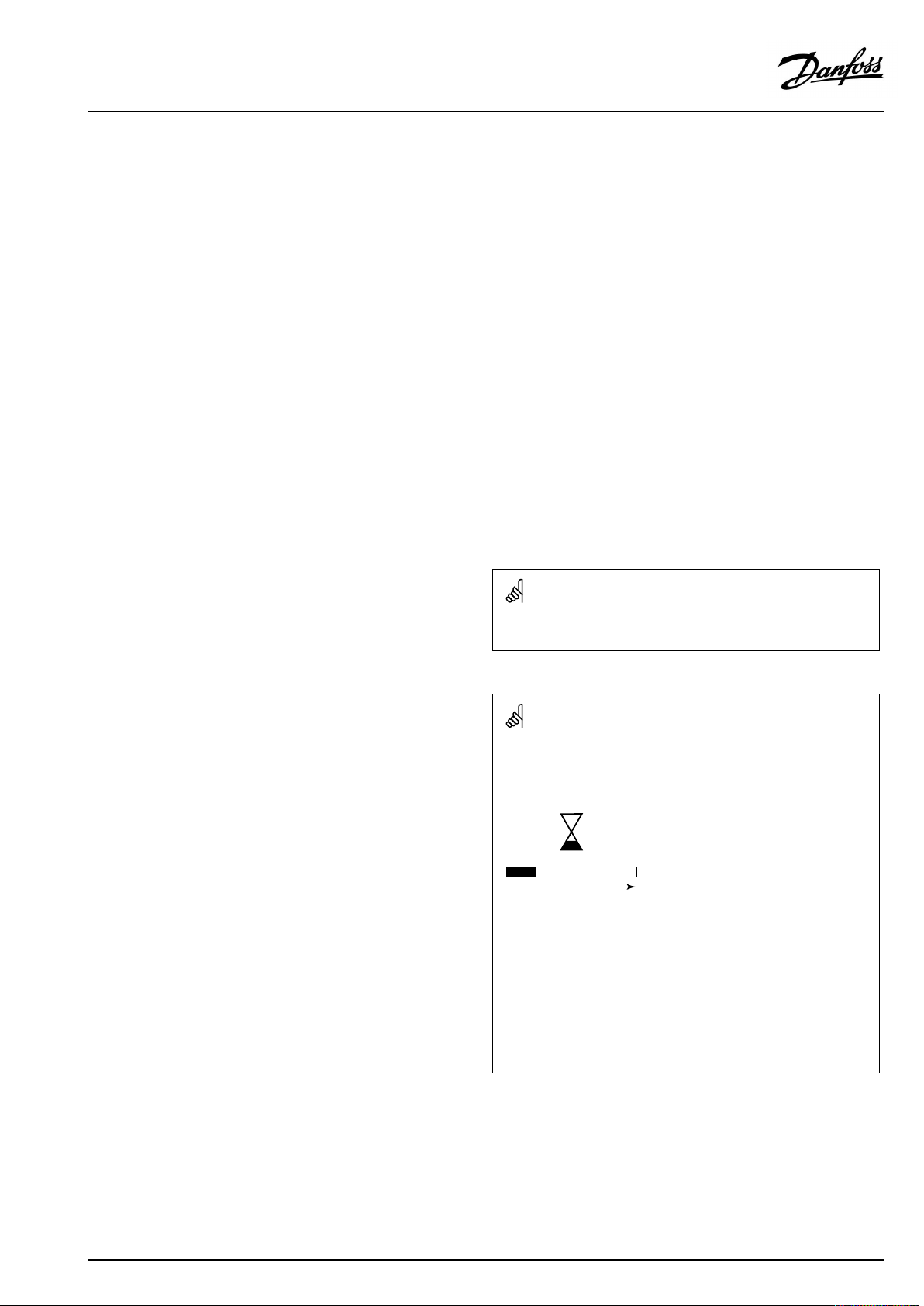
Automaticupdateofcontrollersoftware(firmware):
Thesoftwareofthecontrollerisupdatedautomaticallywhenthekey
isinserted(asofcontrollerversion1.11(ECL210/310)andversion
1.58(ECL296)).Thefollowinganimationwillbeshownwhenthe
softwareisbeingupdated:
Progressbar
Duringupdate:
•DonotremovetheKEY
Ifthekeyisremovedbeforethehour-glassisshown,youhave
tostartafresh.
•Donotdisconnectthepower
Ifthepowerisinterruptedwhenthehour-glassisshown,the
controllerwillnotwork.
•Manualupdateofcontrollersoftware(firmware):
Seethesection"Automatic/manualupdateoffirmware"
AQ150486469826en-010501
©Danfoss|2021.06|3
Page 4
OperatingGuideECLComfort210/296/310,applicationA232/A332
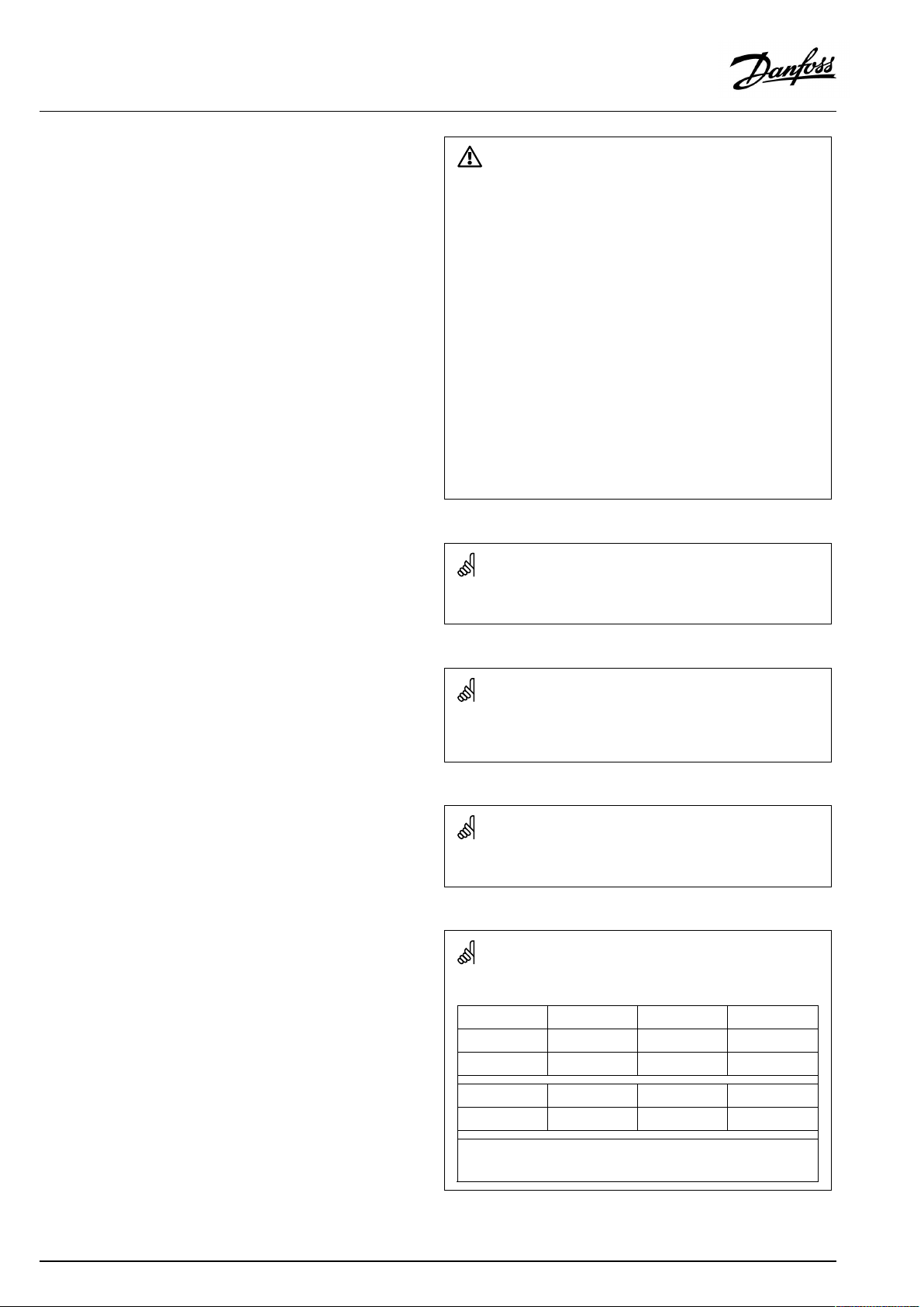
SafetyNote
Toavoidinjuryofpersonsanddamagestothedevice,itisabsolutely
necessarytoreadandobservetheseinstructionscarefully.
Necessaryassembly,start-up,andmaintenanceworkmustbe
performedbyqualifiedandauthorizedpersonnelonly.
Locallegislationsmustberespected.Thiscomprisesalsocable
dimensionsandtypeofisolation(doubleisolatedat230V).
AfusefortheECLComfortinstallationismax.10Atypically.
TheambienttemperaturerangesforECLComfortinoperationare:
ECLComfort210/310:0-55°C
ECLComfort296:0-45°C.
Exceedingthetemperaturerangecanresultinmalfunctions.
Installationmustbeavoidedifthereisariskforcondensation(dew).
Thewarningsignisusedtoemphasizespecialconditionsthatshould
betakenintoconsideration.
Thissymbolindicatesthatthisparticularpieceofinformationshould
bereadwithspecialattention.
AsthisOperatingGuidecoversseveralsystemtypes,specialsystem
settingswillbemarkedwithasystemtype.Allsystemtypesareshown
inthechapter:'Identifyingyoursystemtype'.
°C(degreesCelsius)isameasuredtemperaturevaluewhereasK
(Kelvin)oftenisusedfortemperaturedifferences.
TheIDno.isuniquefortheselectedparameter.
ExampleFirstdigitSeconddigitLastthreedigits
1117411174
-
Circuit1Parameterno.
4|©Danfoss|2021.06
12174
IfanIDdescriptionismentionedmorethanonce,itmeansthatthere
arespecialsettingsforoneormoresystemtypes.Itwillbemarked
withthesystemtypeinquestion(e.g.12174-A266.9).
1
-
2
Circuit2Parameterno.
174
AQ150486469826en-010501
Page 5
OperatingGuideECLComfort210/296/310,applicationA232/A332
ParametersindicatedwithanIDno.like"1x607"meanauniversal
parameter.
xstandsforcircuit/parametergroup.
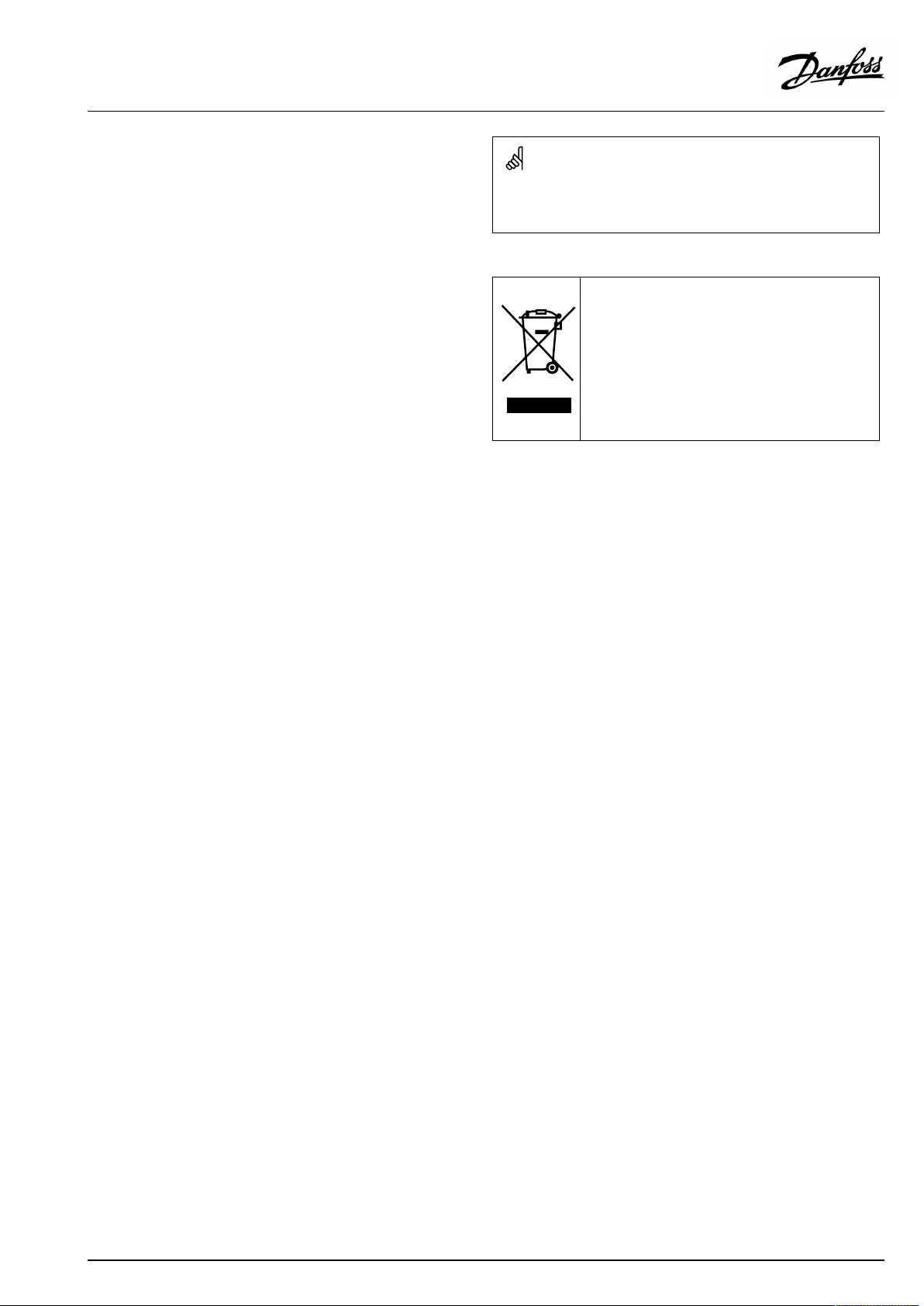
DisposalNote
Thissymbolontheproductindicatesthatitmaynot
bedisposedofashouseholdwaste.
Itmustbehandedovertotheapplicabletake-back
schemefortherecyclingofelectricalandelectronic
equipment.
•Disposeoftheproductthroughchannelsprovided
forthispurpose.
•Complywithalllocalandcurrentlyapplicablelaws
andregulations.
AQ150486469826en-010501
©Danfoss|2021.06|5
Page 6
OperatingGuideECLComfort210/296/310,applicationA232/A332
2.0Installation
2.1Beforeyoustart
TheApplicationKeyA232contains5applications,allrelatedto
floorheatingandceilingcoolingsystems.Theapplicationsinthe
A232keyofferawiderangeofpossibilities(seetheexamples).
TheapplicationA232.1isveryflexible.Thesearethebasic
principles:
Heating/coolingwithroomtemperaturecontrol:
Typically,theflowtemperatureisadjustedaccordingtoyour
requirements.TheflowtemperaturesensorS3isthemost
importantsensor.
ThedesiredflowtemperatureatS3iscalculatedintheECL
controller,basedontheoutdoortemperature(S1)andthedesired
roomtemperature.Thelowertheoutdoortemperature,thehigher
thedesiredflowtemperature(heating).
Oppositely,thehighertheoutdoortemperature,thelowerthe
desiredflowtemperature(cooling).Thechange-overbetween
heatingandcoolingcanbe:
•OutdoorANDroomtemperatureor
•Roomtemperatureor
•Outdoortemperaturerelated.
Bymeansofaweekschedule,thecircuitscanbein‘Comfort’or
‘Saving’mode(twovaluesforthedesiredroomtemperature).In
Savingmodetheheatingcanbereducedorswitchedofftotally.
Themotorizedcontrolvalve(M1)isopenedgraduallywhen:
•(Heating)theflowtemperatureislowerthanthedesiredflow
temperatureandviceversa.
•(Cooling)theflowtemperatureishigherthanthedesiredflow
temperatureandviceversa.
TheON-OFFoutputsX2/X3areactivatedatcooling/heating
demandrespectively.
Roomtemperature:
Ifthemeasuredroomtemperature(S2orECA30/31)doesnot
equalthedesiredroomtemperature,thedesiredtemperatureat
S3canbeadjusted.
Surfacetemperaturelimitation:
Heating
maximuminordertoavoidatoowarmfloor.
Cooling:TheceilingsurfacetemperatureS6canbelimitedtoa
minimuminordertoavoidatoocoldceiling(riskforcondensation).
Override:
WhentheECLcontrollerisinscheduledmode,theS8inputcanbe
usedforoverridingtheScheduletooperateinComfortorSaving
mode.
Coolingmode:
BasedontheRelativeHumidity(RH),measuredbyECA31,the
desiredflowtemperaturecanbeminimumlimitedtoavoiddew
(condensation).
:ThefloorsurfacetemperatureS5canbelimitedtoa
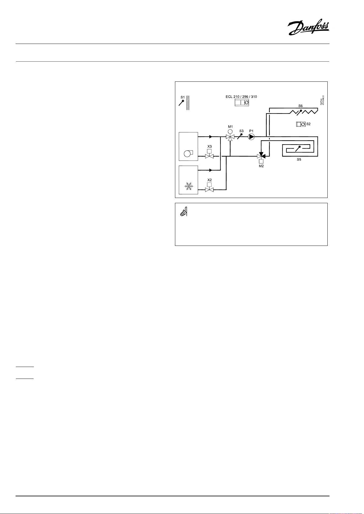
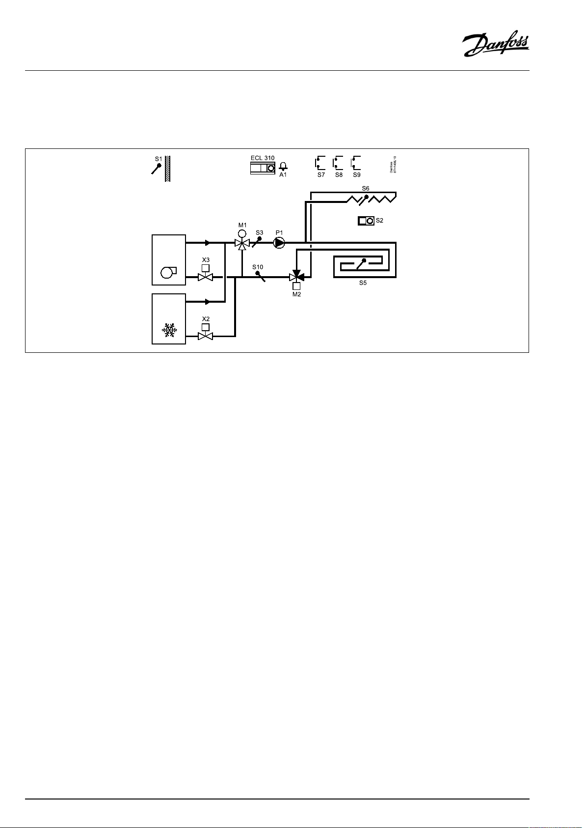
TypicalA232.1application:
Theshowndiagramisafundamentalandsimplifiedexampleanddoes
notcontainallcomponentsthatarenecessaryinasystem.
AllnamedcomponentsareconnectedtotheECLComfortcontroller.
Listofcomponents:
ECL210
/296/310
S1
S2
S3
S4
S5
S6
S7
S8
P1
X2
X3
X4
M1
M2
ElectroniccontrollerECLComfort210,296or310
Outdoortemperaturesensor
ECA31RoomtemperatureandRHsensor*
Flowtemperaturesensor
notused
(Optional)Floorsurfacetemperaturesensor
(Optional)Ceilingsurfacetemperaturesensor
(notillustrated)Overrideinputforstopof
circulationpump
(notillustrated)OverrideinputforComfort/
Saving
Circulationpump(ON/OFF)
Coolingdemand(ON/OFF)
Heatingdemand(ON/OFF)
(notillustrated)Multi-functionality
Motorizedcontrolvalve(3-pointcontrolled)
Motorizedchange-overvalve
*Alternative:ESM-10,roomtemperaturesensor
Thecirculationpump,P1,isONatheatingorcoolingdemandor
atfrostprotection.
6|©Danfoss|2021.06
AQ150486469826en-010501
Page 7

OperatingGuideECLComfort210/296/310,applicationA232/A332
TheON-OFFoutputX4canbesetto
•operateasaHumidistator
•operateasaswitch,dependingontheoutdoortemperatureor
•followSchedule1or
•followSchedule2or
•followSchedule3or
•switchONatcoolingdemand
Alarm(visibleindisplay,nooutput):
Alarmcanbeactivatediftheactualflowtemperaturediffersfrom
thedesiredflowtemperature.
Alarmwillalsobeactivatedif,inheatingmode,theflow
temperatureexceedsasetmax.value.
Safetyfunction,heatingmode:
IftheflowtemperatureS3exceedsasetmax.value,thealarmwill
beactivated.
CirculationpumpP1isswitchedOFFinordertopreventtoohigh
temperaturetobecirculatedinthesystem(forexamplefloor
circuit).
P1isswitchedOFFfor35minutesandthenswitchedONfor30sec.
Iftheflowtemperatureisbelowthesetmax.value,P1remainsON.
Foradescriptionofthechange-overfromheatingtocoolingmode,
pleasereadthesection‘A232ingeneral’ .
AQ150486469826en-010501
©Danfoss|2021.06|7
Page 8
OperatingGuideECLComfort210/296/310,applicationA232/A332
TheapplicationA332.1isverysimilartotheapplicationA232.1.
ExtrasinrelationtoA232.1:
Returntemperaturelimitation:
ThereturntemperatureS10canbelimited,forexamplenotto
betoohigh(heating)ortoolow(cooling).Ifso,thedesiredflow
temperatureatS3canbeadjusted,forexampleatheatingtoa
lowervalueor,atcoolingtoahighervalue.
Thisresultsinagradualclosingofthemotorizedcontrolvalve.
Inboiler-basedheatingsupplythereturntemperatureshouldnot
betoolow(sameadjustmentprocedureasabove).
TheON-OFFoutputX5canbesetto
•followSchedule1or
•followSchedule2or
•followSchedule3or
•switchONatcoolingdemand
AlarmA1:
Analarmactivatesrelay6.
ChangesinrelationtoA332.1:
TheON-OFFoutputX4canbesetto
•operateasaHumidistator
•operateasaswitch,dependingontheoutdoortemperature
Foradescriptionofthechange-overfromheatingtocooling
operation,pleasereadthesection‘A232ingeneral’ .
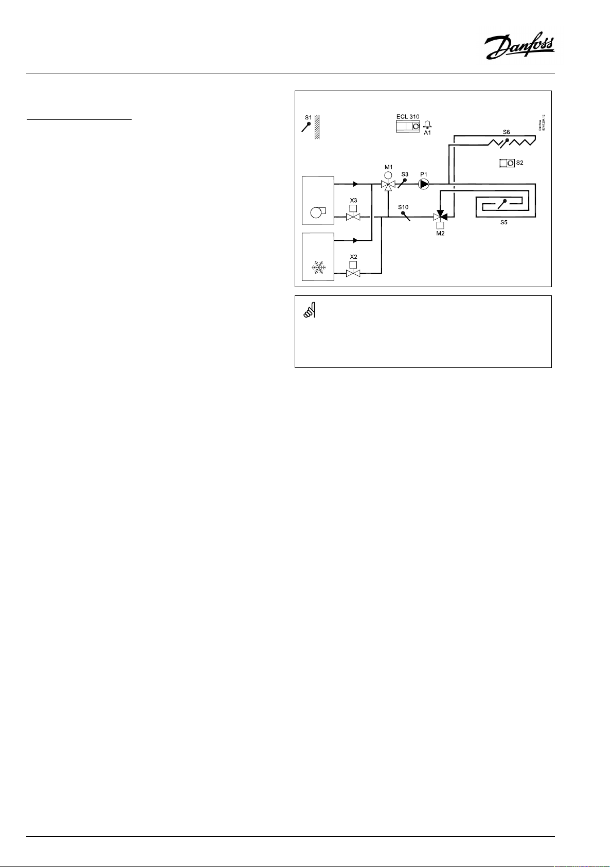
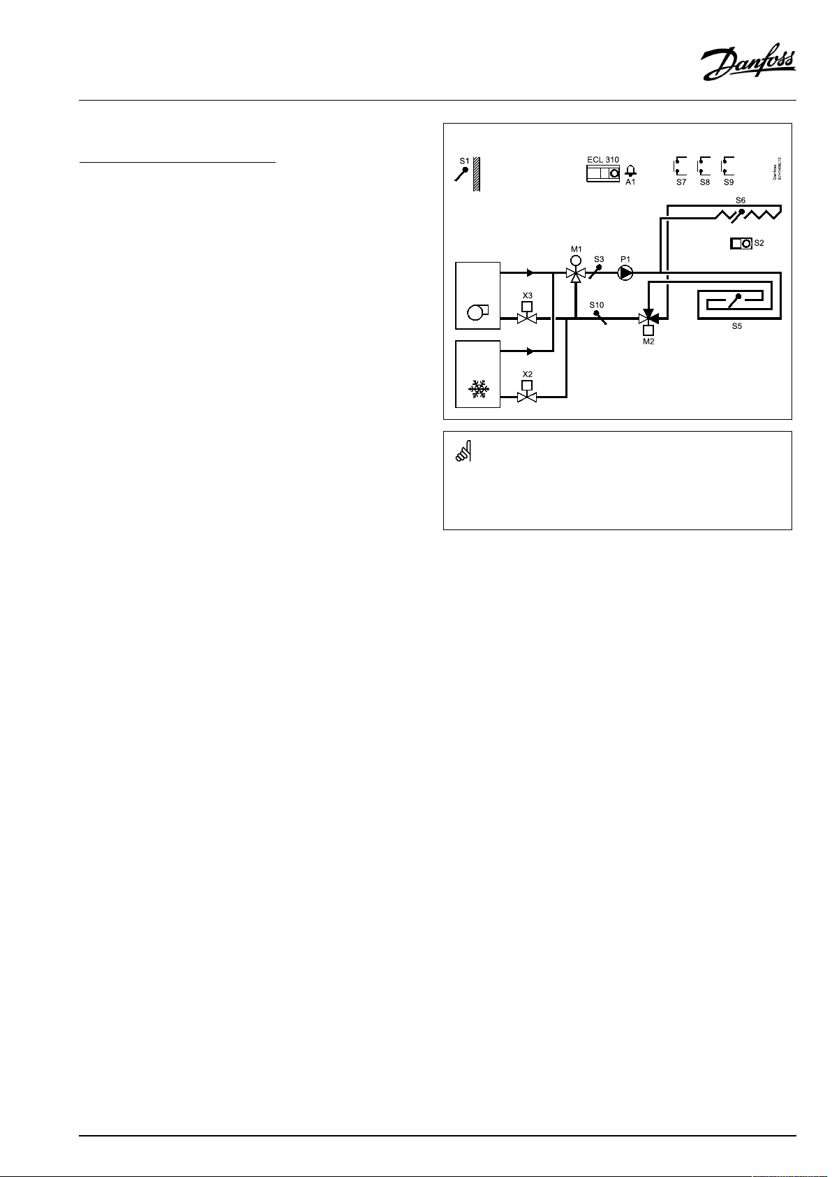
TypicalA332.1application:
Theshowndiagramisafundamentalandsimplifiedexampleanddoes
notcontainallcomponentsthatarenecessaryinasystem.
AllnamedcomponentsareconnectedtotheECLComfortcontroller.
Listofcomponents:
ECL310
S1
S2
S3
S4
S5
S6
S7
ElectroniccontrollerECLComfort310
Outdoortemperaturesensor
ECA31RoomtemperatureandRHsensor*
Flowtemperaturesensor
notused
(Optional)Floorsurfacetemperaturesensor
(Optional)Ceilingsurfacetemperaturesensor
(notillustrated)Overrideinputforstopofcirculation
pump
S8
S9
(notillustrated)OverrideinputforComfort/Saving
notused
S10Returntemperaturesensor
P1
X2
X3
X4
X5
M1
M2
A1
Circulationpump(ON/OFF)
Coolingdemand(ON/OFF)
Heatingdemand(ON/OFF)
(notillustrated)Multi-functionality
(notillustrated)Multi-functionality
Motorizedcontrolvalve(3-pointcontrolled)
Motorizedchange-overvalve
Alarm
*Alternative:ESM-10,roomtemperaturesensor
8|©Danfoss|2021.06
AQ150486469826en-010501
Page 9
OperatingGuideECLComfort210/296/310,applicationA232/A332
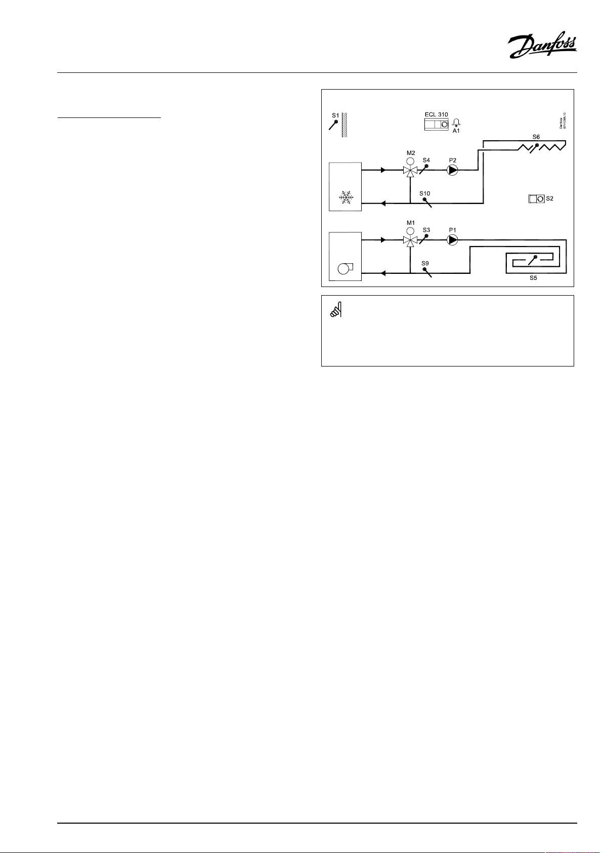
TheapplicationA332.2isbasicallyliketheapplicationA332.1.
ExtrasinrelationtoA332.1:
Heatingandcoolingcircuitshaveseparateflowtemperature
sensorsandcontrolvalves.
Heatingandcoolingcircuitshaveseparatereturntemperature
sensorsandlimitationfunctions.
ChangesinrelationtoA332.1:
P2iscirculationpumpincoolingcircuit
Foradescriptionofthechange-overfromheatingtocooling
operation,pleasereadthesection‘A232ingeneral’ .
TypicalA332.2application:
Theshowndiagramisafundamentalandsimplifiedexampleanddoes
notcontainallcomponentsthatarenecessaryinasystem.
AllnamedcomponentsareconnectedtotheECLComfortcontroller.
Listofcomponents:
ECL310
S1
S2
S3
S4
S5
S6
S7
ElectroniccontrollerECLComfort310
Outdoortemperaturesensor
ECA31RoomtemperatureandRHsensor*
Flowtemperaturesensor,heating
Flowtemperaturesensor,cooling
(Optional)Floorsurfacetemperaturesensor
(Optional)Ceilingsurfacetemperaturesensor
(notillustrated)Overrideinputforstopofcirculation
pump
S8
S9
S10
P1
P2
X3
X4
X5
M1
M2
A1
(notillustrated)OverrideinputforComfort/Saving
Returntemperaturesensor,heating
Returntemperaturesensor,cooling
Circulationpump,heating(ON/OFF)
Circulationpump,cooling(ON/OFF)
Heatingdemand(ON/OFF)
Multi-functionality
Multi-functionality
Motorizedcontrolvalve,heating(3-pointcontrolled)
Motorizedcontrolvalve,cooling(3-pointcontrolled)
Alarm
*Alternative:ESM-10,roomtemperaturesensor
AQ150486469826en-010501
©Danfoss|2021.06|9
Page 10
OperatingGuideECLComfort210/296/310,applicationA232/A332
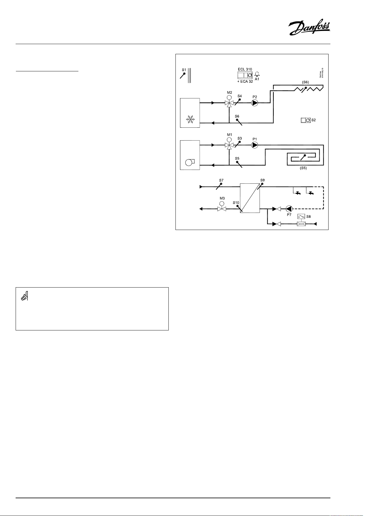
TheapplicationA332.3isbasicallyliketheapplicationA332.2.
ExtrasinrelationtoA332.2:
TemperaturesensorsS5(heatingcircuit)andS6(coolingcircuit)
canbeusedforeitherreturntemperaturelimitationorsurface
temperaturelimitation.Functionalityselectionisdonebysetting
aninfluencefactor.IfinfluencefactorsaresetforbothReturnand
Surfacelimitation,therewillnotbeanylimitation.
AdvancedDomesticHotWater(DHW)heatingcontrol:
TheDHWtemperatureatS9ismaintainedat‘Comfort’levelata
DHWdraw-off(DHWtapping)(theflowswitchS8isactivated).
IfthemeasuredDHWtemperatureatS9islowerthanthedesired
DHWtemperature,themotorizedcontrolvalveM3isopened
graduallyandviceversa.
TheDHWtemperaturecontrolisinrelationtoactualsupply
temperatureS7.Inordertocompensateforthereactiontime,
themotorizedcontrolvalvecanbepre-activatedatthestartofa
DHWdraw-off.
Anidletemperature(thedesiredSavingtemperature)canbe
maintainedateitherS7orS9whenthereisnoDHWdraw-off.
Bymeansofaweekschedule,theDHWcircuitcanbein‘Comfort’
or‘Saving’mode(twovaluesforthedesiredDHWtemperature).
ThereturntemperatureS10canbelimited,forexamplenottobe
toohighortoolow.
Ifso,thedesiredflowtemperatureatS9canbeadjusted,for
exampletoalowervalue.Thisresultsinagradualclosingofthe
motorizedcontrolvalve.
Ananti-bacteriafunctionisavailableforactivationonselected
daysoftheweek.
Foradescriptionofthechange-overfromheatingtocooling
operation,pleasereadthesection‘A232ingeneral’ .
Theshowndiagramisafundamentalandsimplifiedexampleanddoes
notcontainallcomponentsthatarenecessaryinasystem.
AllnamedcomponentsareconnectedtotheECLComfortcontroller.
TypicalA332.3application:
Listofcomponents:
ECL310
ECA32
S1
S2
S3
S4
S5
S6
ElectroniccontrollerECLComfort310
Built-inextensionmodule
Outdoortemperaturesensor
ECA31RoomtemperatureandRHsensor*
Flowtemperaturesensor,heating
Flowtemperaturesensor,cooling
(Optional)ReturnorFloorsurfacetemperaturesensor
(Optional)ReturnorCeilingsurfacetemperature
sensor
S7
S8
S9
Supplytemperaturesensor,DHW
Flowswitch,DHWdraw-off
Flowtemperaturesensor,DHW
S10Returntemperaturesensor,DHW
P1
P2
P7
X3
X4
X5
M1
M2
M3
A1
Circulationpump,heating(ON/OFF)
Circulationpump,cooling(ON/OFF)
Circulationpump,DHW(ON/OFF)
(notillustrated)Heatingdemand(ON/OFF)
(notillustrated)Multi-functionality
(notillustrated)Multi-functionality
Motorizedcontrolvalve,heating(3-pointcontrolled)
Motorizedcontrolvalve,cooling(3-pointcontrolled)
Motorizedcontrolvalve,DHW(3-pointcontrolled)
Alarm
*Alternative:ESM-10,roomtemperaturesensor
10|©Danfoss|2021.06
AQ150486469826en-010501
Page 11
OperatingGuideECLComfort210/296/310,applicationA232/A332
TheapplicationA332.4isbasicallyliketheapplicationA332.1.
Extras/changesinrelationtoA332.1:
Override:
WhentheECLcontrollerisinscheduledmode-
•theS7inputcanbeusedforoverridingtoHeatingmode
•theS9inputcanbeusedforoverridingtoCoolingmode
Foradescriptionofthechange-overfromheatingtocooling
operation,pleasereadthesection‘A232ingeneral’ .
TypicalA332.4application:
Theshowndiagramisafundamentalandsimplifiedexampleanddoes
notcontainallcomponentsthatarenecessaryinasystem.
AllnamedcomponentsareconnectedtotheECLComfortcontroller.
Listofcomponents:
ECL310
S1
S2
S3
S4
S5
S6
S7
S8
S9
ElectroniccontrollerECLComfort310
Outdoortemperaturesensor
ECA31RoomtemperatureandRHsensor*
Flowtemperaturesensor
notused
(Optional)Floorsurfacetemperaturesensor
(Optional)Ceilingsurfacetemperaturesensor
OverrideinputforHeatingmode
OverrideinputforComfort/Saving
OverrideinputforCoolingmode
S10Returntemperaturesensor
P1
X2
X3
X4
X5
M1
M2
A1
Circulationpump(ON/OFF)
Coolingdemand(ON/OFF)
Heatingdemand(ON/OFF)
(notillustrated)Multi-functionality
(notillustrated)Multi-functionality
Motorizedcontrolvalve(3-pointcontrolled)
Motorizedchange-overvalve
Alarm
*Alternative:ESM-10,roomtemperaturesensor
AQ150486469826en-010501
©Danfoss|2021.06|11
Page 12
OperatingGuideECLComfort210/296/310,applicationA232/A332
A232,ingeneral
Thefunctionselector:
Eachcircuithasafunctionselector.Theheatingcircuitcanrun,
forexample
•Comfortperiodsatadesiredroomtemperatureof21°C
•Savingperiodsatadesiredroomtemperatureof16°CorTotal
stop
Thecoolingcircuitcanrun,forexample
•Comfortperiodsatadesiredroomtemperatureof24°C
•Savingperiodsatadesiredroomtemperatureof30°C
Schedules:
TheA232applicationcontains3weekschedules;oneforthe
heatingcircuitandoneforthecoolingcircuit.Thethirdscheduleis
foruniversaluseandisfoundin'Commoncontrollersettings'.
A232.1:Relay4(X4)canbesettofollowthethirdschedule.
A332.1,A332.2,A332.3andA332.4:Relay5(X5)canbesettofollow
thethirdschedule.
Overridefunctions:
Bymeansofswitches,connectedtodifferentinputs,thefollowing
functionalitiesareavailablewhentheinputinquestionisactivated:
S7S8S9
A232.1
A332.1
A332.2
A332.3
A332.4
Stopthecirculationpump
Stopthecirculationpump
Stopthecirculationpump
NofunctionNofunctionNofunction
OverridetoHeating
OverridetoComfortorSavingmodeNofunction
OverridetoComfortorSavingmodeNofunction
OverridetoComfortorSavingmodeNofunction
OverridetoComfortorSavingmode
OverridetoCooling
12|©Danfoss|2021.06
AQ150486469826en-010501
Page 13

OperatingGuideECLComfort210/296/310,applicationA232/A332
A232,ingeneral,continued
Shortprocessdescriptions:
Changefromheatingtocooling(outdoorandroomtemperature
based):
1.Heatingactive
2.Outdoorandroomtemperaturerising
3.Heatingstopwhenactualoutdoortemperaturegetshigher
than'Summer,cut-out'(ID1x179)
4.Coolingstartwhen:
•Accumulatedoutdoortemperaturevaluegetshigherthan
setlimit('Activation,acc.T' ,ID12144)
AND
•Accumulatedroomtemperaturevaluegetshigherthanset
limit('Act.,acc.roomT',ID12156)
AND
•Actualroomtemperaturegetshigherthandesiredroom
temperatureforcoolingoperation.
Changefromheatingtocooling(roomtemperaturebased):
1.Heatingactive
2.Roomtemperaturerising
3.Heatingstopwhenaccumulatedroomtemperaturevaluegets
higherthandesiredroomtemperatureforheatingoperation.
4.Coolingstartwhen:
•Accumulatedroomtemperaturevaluegetshigherthanset
limit('Act.,acc.roomT',ID12156)
AND
•Actualroomtemperaturegetshigherthandesiredroom
temperatureforcoolingoperation.
Thecontrollerispre-programmedwithfactorysettingsthatareshown
inthe‘ParameterIDoverview’appendix.
AQ150486469826en-010501
©Danfoss|2021.06|13
Page 14
OperatingGuideECLComfort210/296/310,applicationA232/A332
2.2Identifyingthesystemtype
Sketchyourapplication
TheECLComfortcontrollerseriesisdesignedforawiderange
ofheating,domestichot-water(DHW)andcoolingsystemswith
differentconfigurationsandcapacities.Ifyoursystemdiffers
fromthediagramsshownhere,youmaywanttomakeasketch
ofthesystemabouttobeinstalled.Thismakesiteasiertouse
theOperatingGuide,whichwillguideyoustep-by-stepfrom
installationtofinaladjustmentsbeforetheend-usertakesover.
TheECLComfortcontrollerisauniversalcontrollerthatcanbe
usedforvarioussystems.Basedontheshownstandardsystems,
itispossibletoconfigureadditionalsystems.Inthischapteryou
findthemostfrequentlyusedsystems.Ifyoursystemisnotquite
asshownbelow,findthediagramwhichhasthebestresemblance
withyoursystemandmakeyourowncombinations.
SeetheInstallationGuide(deliveredwiththeapplicationkey)for
applicationtypes/sub-types.
Thecirculationpump(s)inheatingcircuit(s)canbeplacedintheflow
aswellasthereturn.Placethepumpaccordingtothemanufacturer’s
specification.
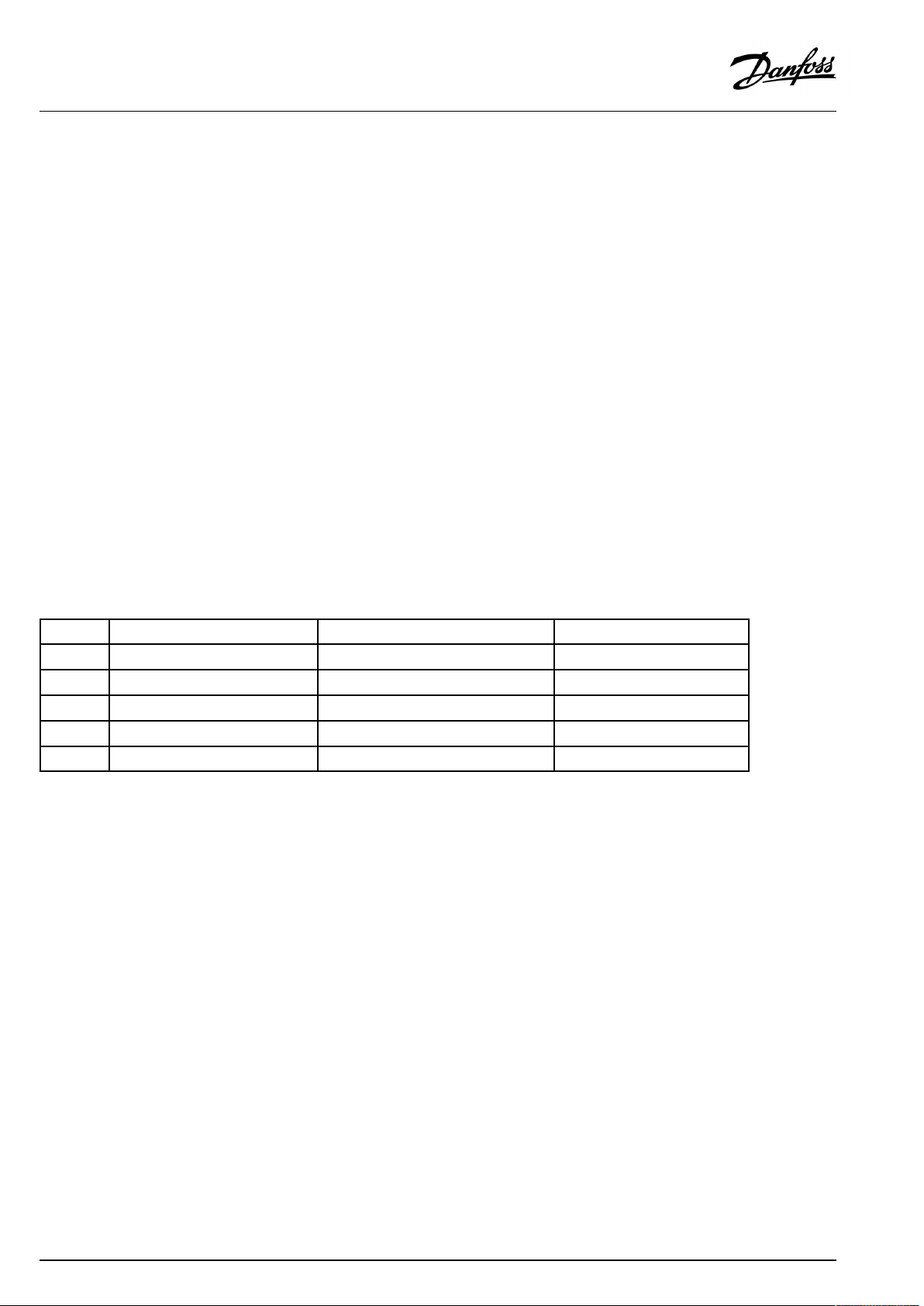
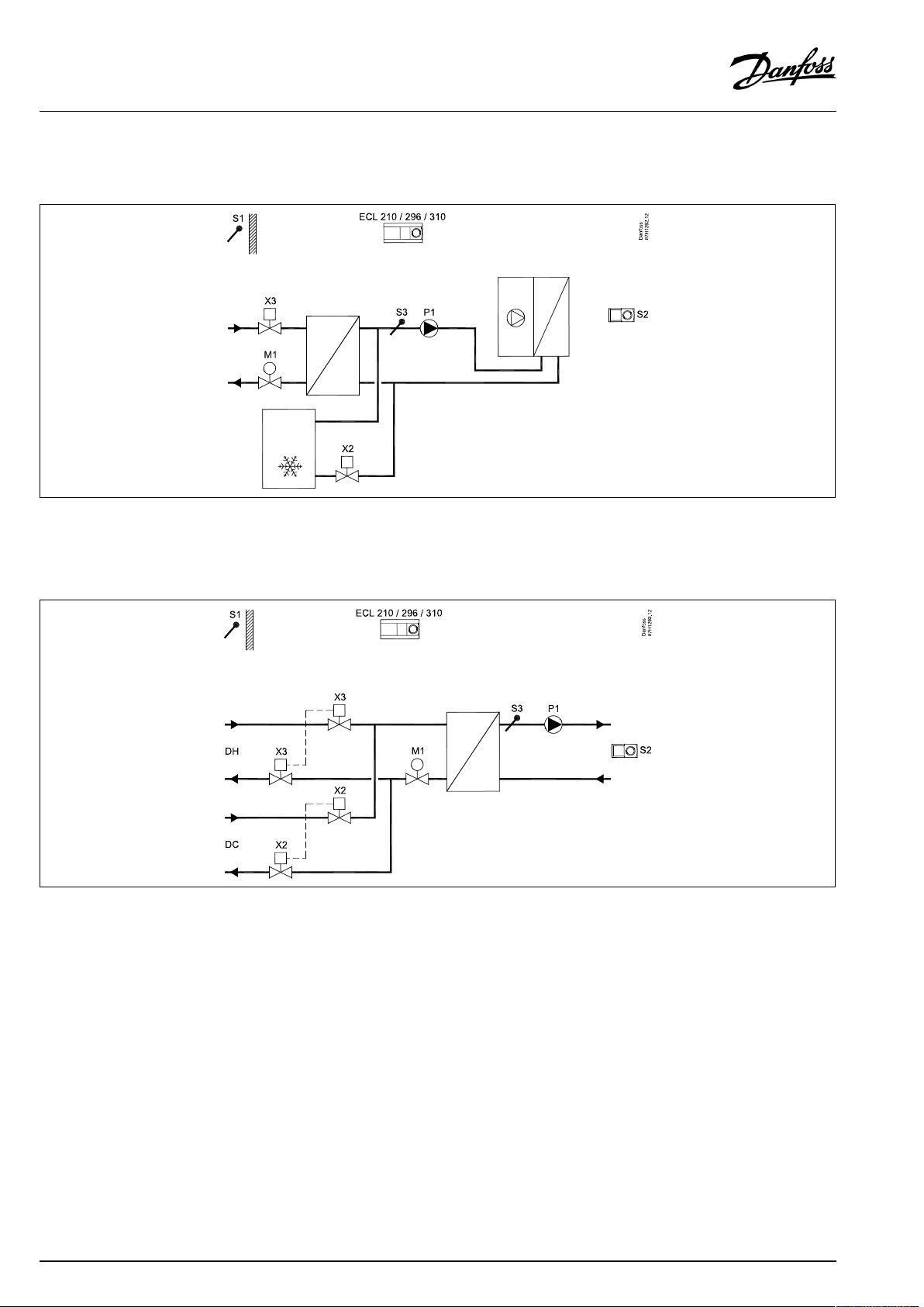
A232.1,ex.a:
Controlofflowtemperature(heatinginfloor/coolinginceiling)inrelationtooutdoor,roomanddewpointtemperature.Optional
surfacetemperaturelimitations.
14|©Danfoss|2021.06
AQ150486469826en-010501
Page 15
OperatingGuideECLComfort210/296/310,applicationA232/A332
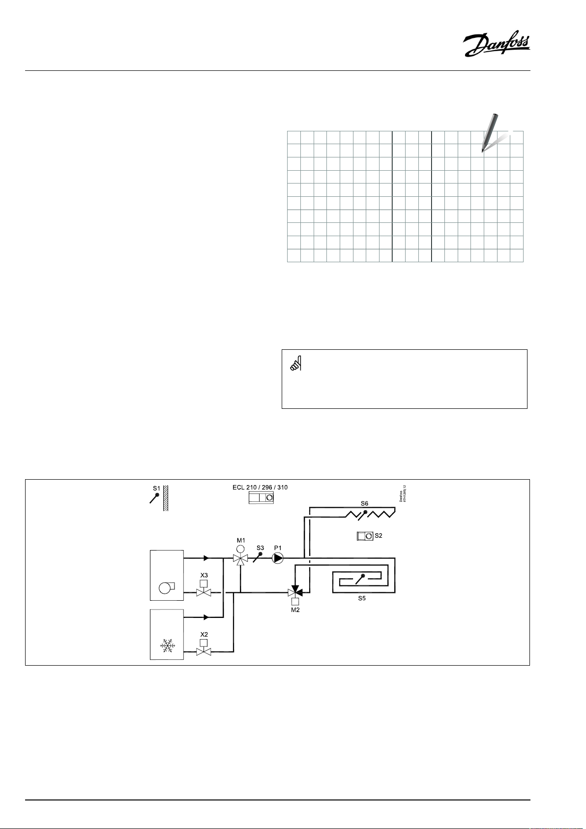
A232.1,ex.b:
Controlofflowtemperature(heating/cooling)infloorinrelationtooutdoor,roomanddewpointtemperature.Optionalsurface
temperaturelimitation.
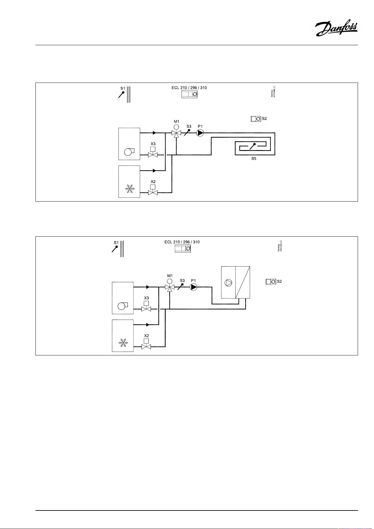
A232.1,ex.c:
Controlofflowtemperature(heating/cooling)toafan-coilinrelationtooutdoor,roomanddewpointtemperature.
AQ150486469826en-010501
©Danfoss|2021.06|15
Page 16
OperatingGuideECLComfort210/296/310,applicationA232/A332
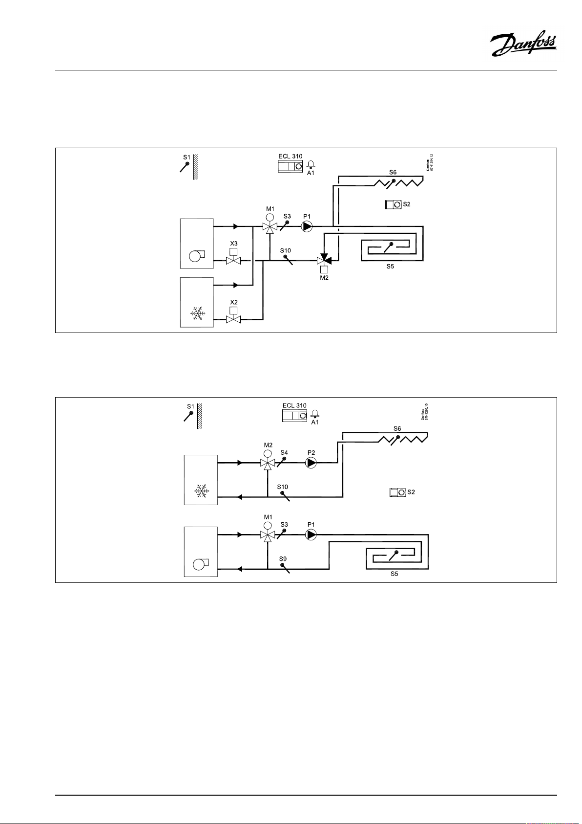
A232.1,ex.d:
Controlofflowtemperature(heating/cooling)toafan-coilinrelationtooutdoor,roomanddewpointtemperature.Heatingsource:
Districtheating.Coolingsource:Coolingmachine.
A232.1,ex.e:
Controlofflowtemperature(heating/cooling)inrelationtooutdoor,roomanddewpointtemperature.Heating/coolingsources:
Districtheating/districtcooling.
16|©Danfoss|2021.06
AQ150486469826en-010501
Page 17
OperatingGuideECLComfort210/296/310,applicationA232/A332
A332.1,ex.a:
Controlofflowtemperature(heatinginfloor/coolinginceiling)inrelationtooutdoor,roomanddewpointtemperature.Optionalreturn
andsurfacetemperaturelimitation.
AllA232.1examplescanbecontrolledbyA332.1.
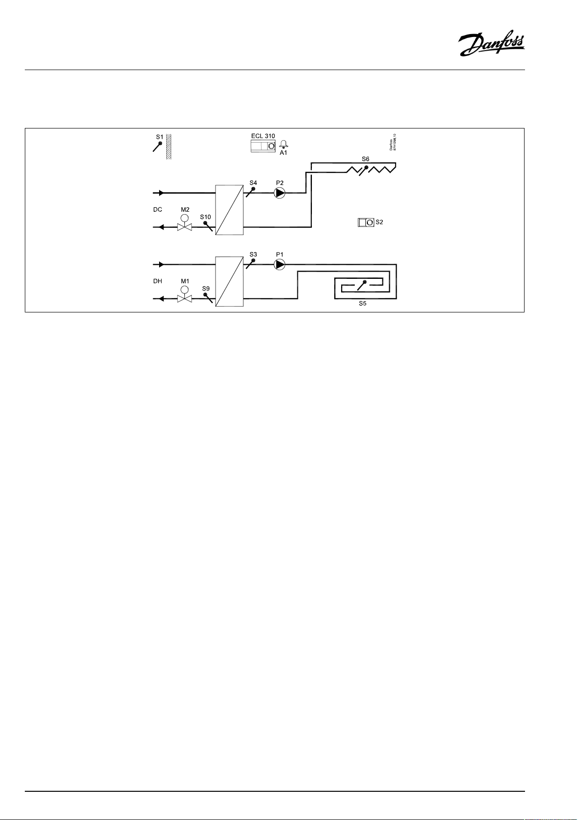
A332.2,ex.a:
Separatedcontrolofflowtemperaturesforheating/coolinginrelationtooutdoor,roomanddewpointtemperature.Optionalreturn
andsurfacetemperaturelimitations.
AQ150486469826en-010501
©Danfoss|2021.06|17
Page 18
OperatingGuideECLComfort210/296/310,applicationA232/A332
A332.2,ex.b:
Districtheating/districtcoolingbasedcontrolofflowtemperaturesforheating/coolinginrelationtooutdoor,roomanddewpoint
temperature.Optionalreturnandsurfacetemperaturelimitations.
18|©Danfoss|2021.06
AQ150486469826en-010501
Page 19
OperatingGuideECLComfort210/296/310,applicationA232/A332
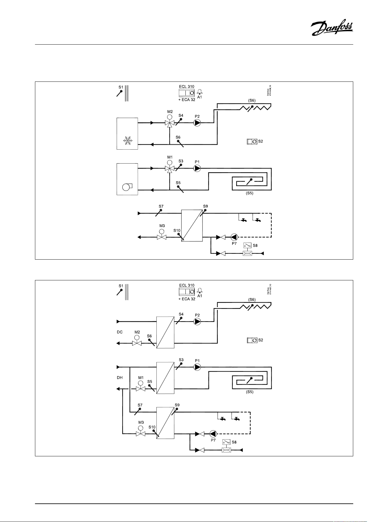
A332.3,ex.aandb:
Separatedcontrolofflowtemperaturesforheating/coolinginrelationtooutdoor,roomanddewpointtemperature.AdvancedDHW
temperaturecontrolatDHWdraw-off.Anti-bacteriatemperaturecontrol.Optionalreturnorsurfacetemperaturelimitations.
AQ150486469826en-010501
©Danfoss|2021.06|19
Page 20
OperatingGuideECLComfort210/296/310,applicationA232/A332
A332.4,ex.a:
Controlofflowtemperature(heatinginfloor/coolinginceiling)inrelationtooutdoor,roomanddewpointtemperature.Optionalreturn
andsurfacetemperaturelimitation.Overridefunctionalitiesforheatingandcoolingmodes.
TheA232.1andA332.1examplescan,ingeneral,becontrolledbyA332.4.
20|©Danfoss|2021.06
AQ150486469826en-010501
Page 21
OperatingGuideECLComfort210/296/310,applicationA232/A332
2.3Mounting
2.3.1MountingtheECLComfortcontroller
SeetheInstallationGuidewhichisdeliveredtogetherwiththe
ECLComfortcontroller.
Foreasyaccess,youshouldmounttheECLComfortcontrollernear
thesystem.
ECLComfort210/296/310canbemounted
•onawall
•onaDINrail(35mm)
ECLComfort296canbemounted
•inapanelcut-out
ECLComfort210canbemountedinanECLComfort310basepart
(forfutureupgrade).
Screws,PGcableglandsandrawlplugsarenotsupplied.
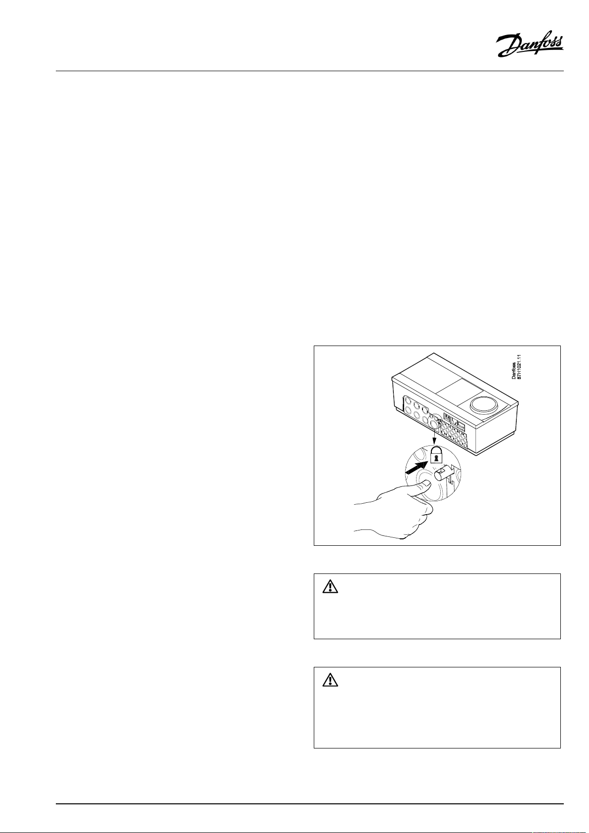
LockingtheECLComfort210/310controller
InordertofastentheECLComfortcontrollertoitsbasepart,secure
thecontrollerwiththelockingpin.
Topreventinjuriestopersonsorthecontroller,thecontrollerhasto
besecurelylockedintothebase.Forthispurpose,pressthelocking
pinintothebaseuntilaclickisheardandthecontrollernolonger
canberemovedfromthebase.
Ifthecontrollerisnotsecurelylockedintothebasepart,thereisarisk
thatthecontrollerduringoperationcanunlockfromthebaseandthe
basewithterminals(andalsothe230Va.c.connections)areexposed.
Topreventinjuriestopersons,alwaysmakesurethatthecontroller
issecurelylockedintoitsbase.Ifthisisnotthecase,thecontroller
shouldnotbeoperated!
AQ150486469826en-010501
©Danfoss|2021.06|21
Page 22
OperatingGuideECLComfort210/296/310,applicationA232/A332
Theeasywaytolockthecontrollertoitsbaseorunlockitistousea
screwdriveraslever.
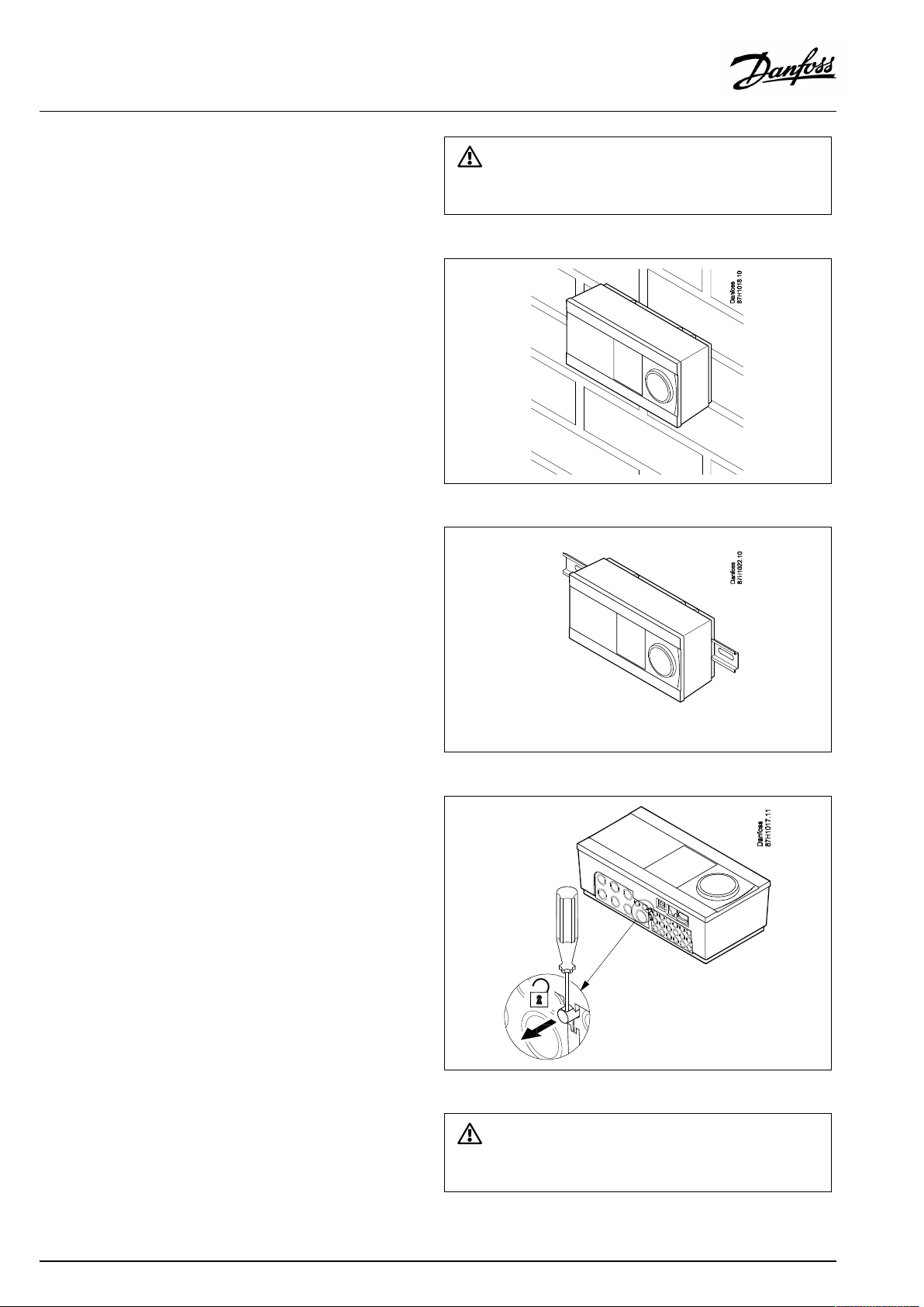
Mountingonawall
Mountthebasepartonawallwithasmoothsurface.Establishthe
electricalconnectionsandpositionthecontrollerinthebasepart.
Securethecontrollerwiththelockingpin.
MountingonaDINrail(35mm)
MountthebasepartonaDINrail.Establishtheelectrical
connectionsandpositionthecontrollerinthebasepart.Secure
thecontrollerwiththelockingpin.
DismountingtheECLComfortcontroller
Inordertoremovethecontrollerfromthebasepart,pulloutthe
lockingpinbymeansofascrewdriver.Thecontrollercannowbe
removedfromthebasepart.
Theeasywaytolockthecontrollertoitsbaseorunlockitistousea
screwdriveraslever.
22|©Danfoss|2021.06
AQ150486469826en-010501
Page 23
OperatingGuideECLComfort210/296/310,applicationA232/A332
BeforeremovingtheECLComfortcontrollerfromthebasepart,ensure
thatthesupplyvoltageisdisconnected.
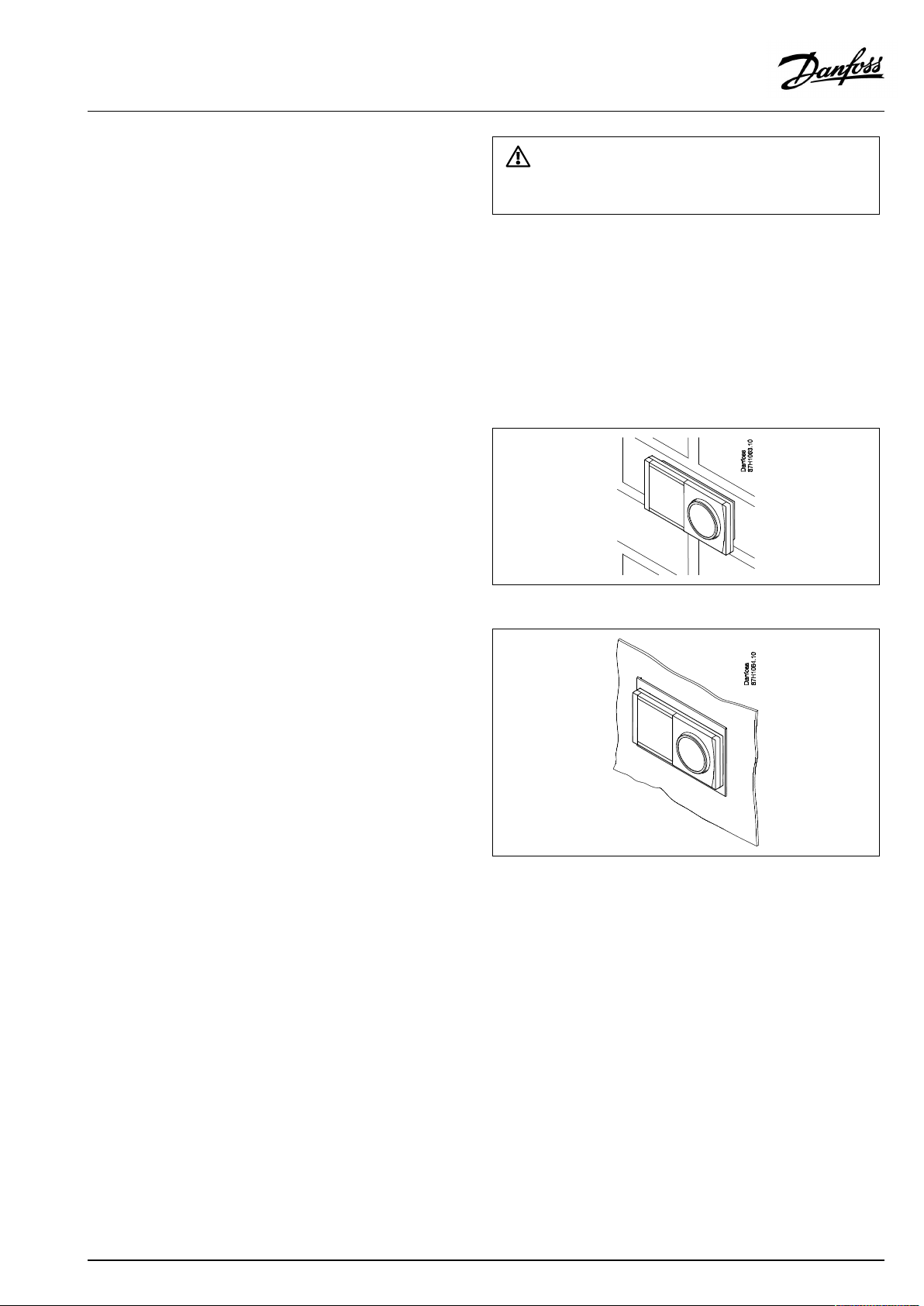
2.3.2MountingtheRemoteControlUnitsECA30/31
Selectoneofthefollowingmethods:
•Mountingonawall,ECA30/31
•Mountinginapanel,ECA30
Screwsandrawlplugsarenotsupplied.
Mountingonawall
MountthebasepartoftheECA30/31onawallwithasmooth
surface.Establishtheelectricalconnections.PlacetheECA30/
31inthebasepart.
Mountinginapanel
MounttheECA30inapanelusingtheECA30framekit(ordercode
no.087H3236).Establishtheelectricalconnections.Securethe
framewiththeclamp.PlacetheECA30inthebasepart.TheECA
30canbeconnectedtoanexternalroomtemperaturesensor.
TheECA31mustnotbemountedinapanelifthehumidity
functionistobeused.
AQ150486469826en-010501
©Danfoss|2021.06|23
Page 24
OperatingGuideECLComfort210/296/310,applicationA232/A332
2.3.3MountingtheinternalI/OmoduleECA32
MountingoftheinternalI/OmoduleECA32
TheECA32module(ordercodeno.087H3202)mustbeinserted
intotheECLComfort310/310Bbasepartforadditionalinputand
outputsignalsinrelevantapplications.
TheconnectionbetweentheECLComfort310/310BandECA32
isa10-pole(2x5)connector.Theconnectionisautomatically
establishedwhentheECLComfort310/310Bisplacedonthe
basepart.
24|©Danfoss|2021.06
AQ150486469826en-010501
Page 25
OperatingGuideECLComfort210/296/310,applicationA232/A332
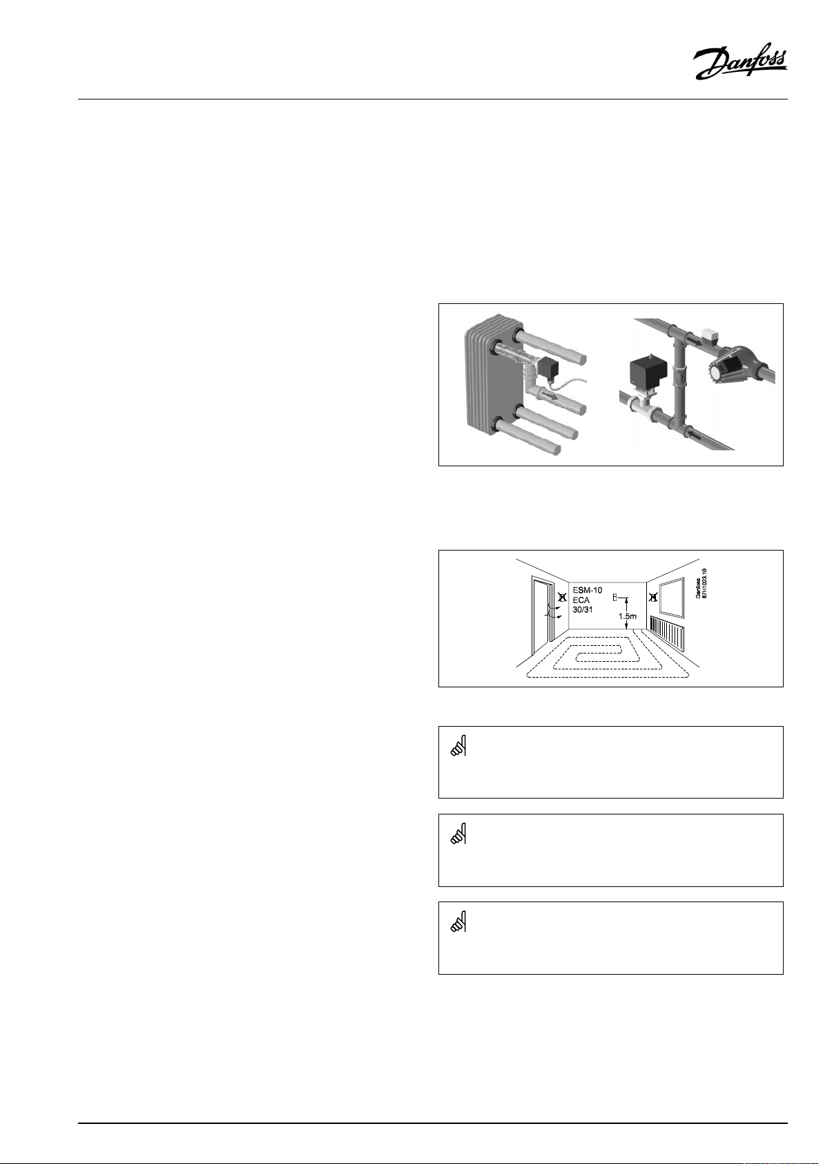
2.4Placingthetemperaturesensors
2.4.1Placingthetemperaturesensors
Itisimportantthatthesensorsaremountedinthecorrectposition
inyoursystem.
Thetemperaturesensormentionedbelowaresensorsusedforthe
ECLComfort210/296/310serieswhichnotallwillbeneeded
foryourapplication!
Outdoortemperaturesensor(ESMT)
Theoutdoorsensorshouldbemountedonthatsideofthebuilding
whereitislesslikelytobeexposedtodirectsunshine.Itshouldnot
beplacedclosetodoors,windowsorairoutlets.
Flowtemperaturesensor(ESMU,ESM-11orESMC)
Placethesensormax.15cmfromthemixingpoint.Insystems
withheatexchanger,DanfossrecommendsthattheESMU-typeto
beinsertedintotheexchangerflowoutlet.
Makesurethatthesurfaceofthepipeiscleanandevenwhere
thesensorismounted.
Returntemperaturesensor(ESMU,ESM-11orESMC)
Thereturntemperaturesensorshouldalwaysbeplacedsothatit
measuresarepresentativereturntemperature.
Roomtemperaturesensor
(ESM-10,ECA30/31RemoteControlUnit)
Placetheroomsensorintheroomwherethetemperatureistobe
controlled.Donotplaceitonoutsidewallsorclosetoradiators,
windowsordoors.
Boilertemperaturesensor(ESMU,ESM-11orESMC)
Placethesensoraccordingtotheboilermanufacturer’s
specification.
Airducttemperaturesensor(ESMB-12orESMUtypes)
Placethesensorsothatitmeasuresarepresentativetemperature.
DHWtemperaturesensor(ESMUorESMB-12)
PlacetheDHWtemperaturesensoraccordingtothemanufacturer’s
specification.
Slabtemperaturesensor(ESMB-12)
Placethesensorinaprotectiontubeintheslab.
ESM-11:Donotmovethesensorafterithasbeenfastenedinorderto
avoiddamagetothesensorelement.
ESM-11,ESMCandESMB-12:Useheatconductingpasteforquick
measurementofthetemperature.
ESMUandESMB-12:Usingasensorpockettoprotectthesensorwill,
however,resultinaslowertemperaturemeasurement.
AQ150486469826en-010501
©Danfoss|2021.06|25
Page 26
OperatingGuideECLComfort210/296/310,applicationA232/A332
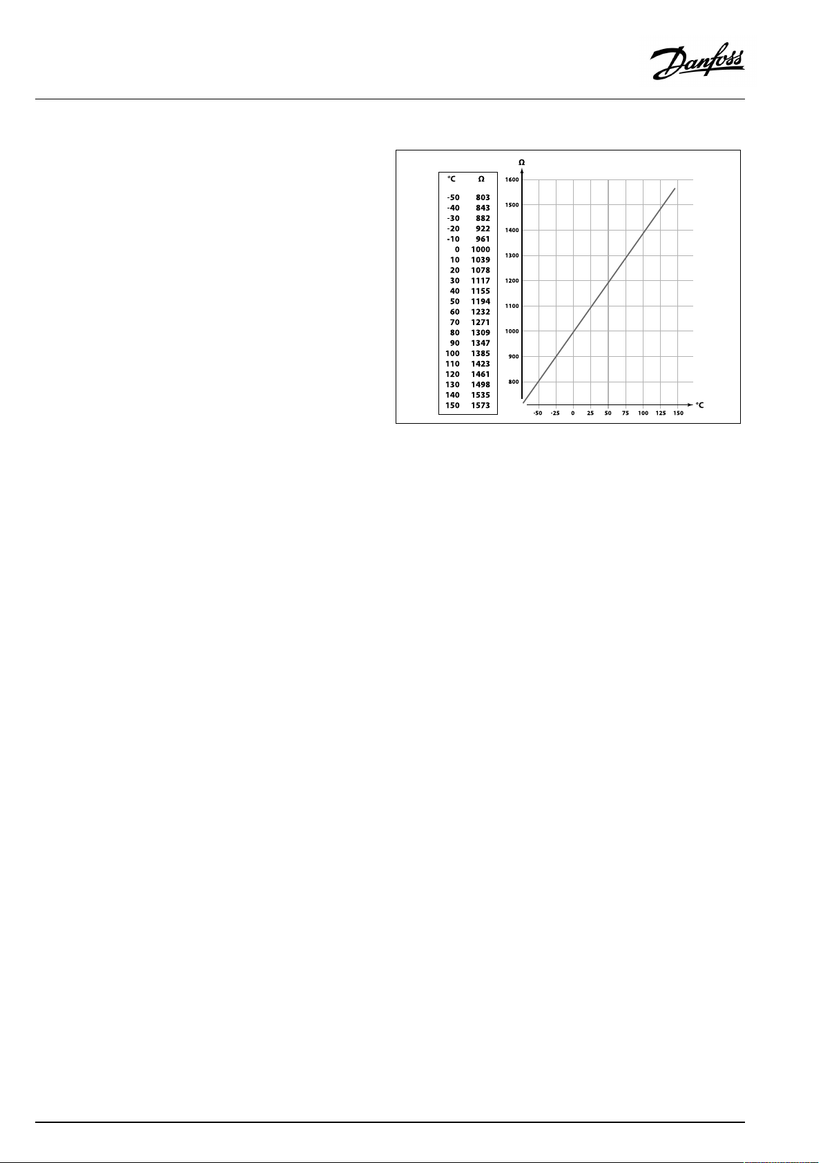
Pt1000temperaturesensor(IEC751B,1000Ω/0°C)
Relationshipbetweentemperatureandohmicvalue:
26|©Danfoss|2021.06
AQ150486469826en-010501
Page 27
OperatingGuideECLComfort210/296/310,applicationA232/A332
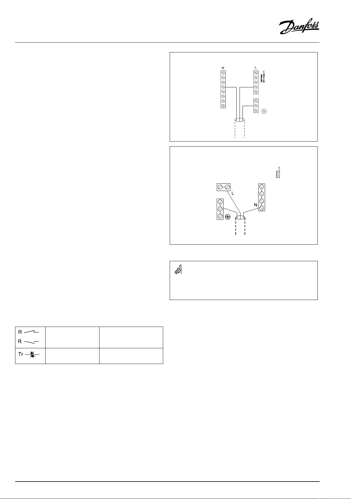
2.5Electricalconnections
2.5.1Electricalconnections230Va.c.
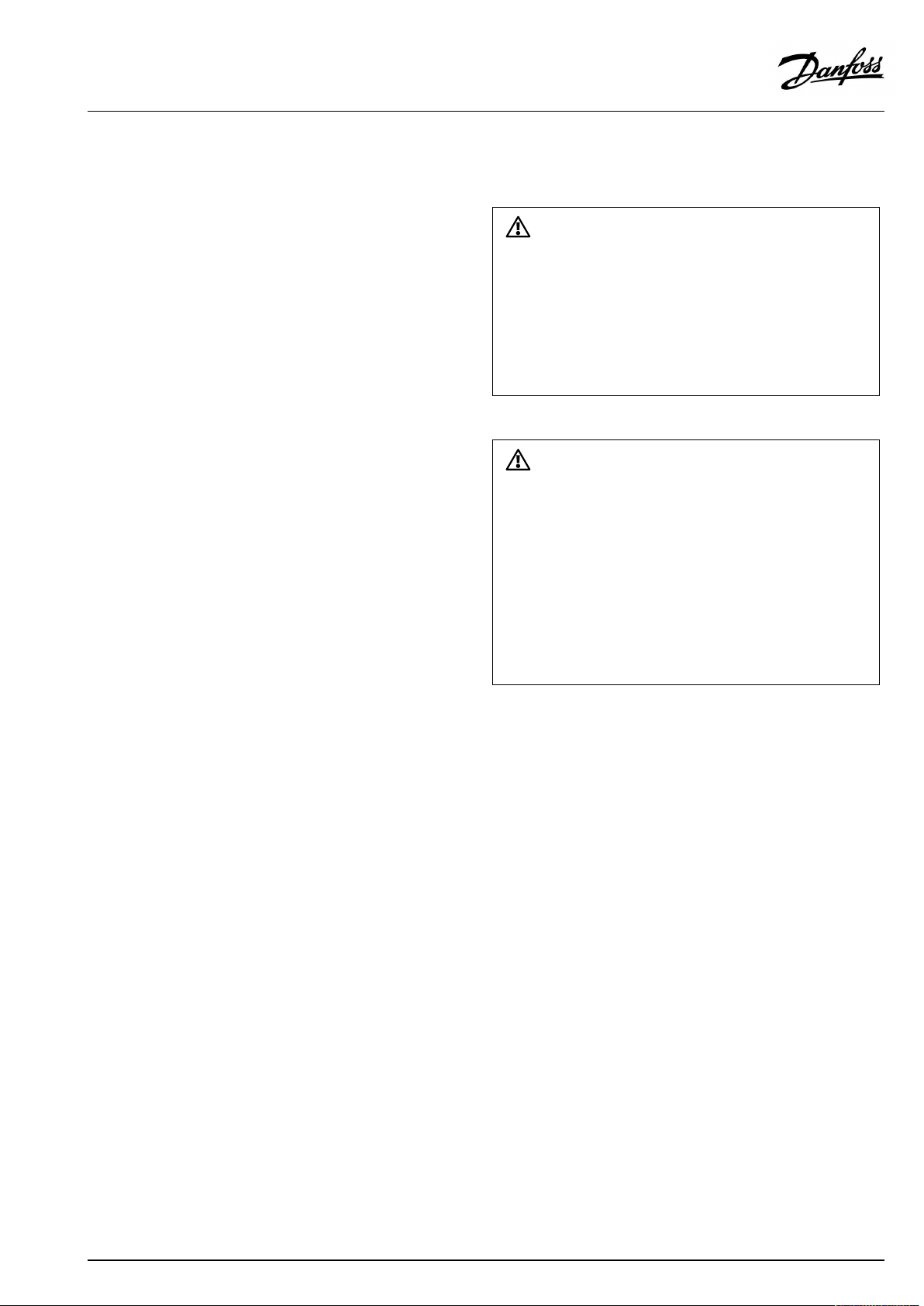
Warning
ElectricconductorsonPCB(PrintedCircuitBoard)forsupplyvoltage,
relaycontactsandtriacoutputsdonothavemutualsafetydistanceof
minimum6mm.Theoutputsarenotallowedtobeusedasgalvanic
separated(voltfree)outputs.
Ifagalvanicseparatedoutputisneeded,anauxiliaryrelayis
recommended.
24Voltcontrolledunits,forexampleactuators,aretobecontrolledby
meansofECLComfort310,24Voltversion.
SafetyNote
Necessaryassembly,start-up,andmaintenanceworkmustbe
performedbyqualifiedandauthorizedpersonnelonly.
Locallegislationsmustberespected.Thiscomprisesalsocablesize
andisolation(reinforcedtype).
AfusefortheECLComfortinstallationismax.10Atypically.
TheambienttemperaturerangefortheECLComfortinoperationis
0-55°C.Exceedingthistemperaturerangecanresultinmalfunctions.
Installationmustbeavoidedifthereisariskforcondensation(dew).
AQ150486469826en-010501
©Danfoss|2021.06|27
Page 28
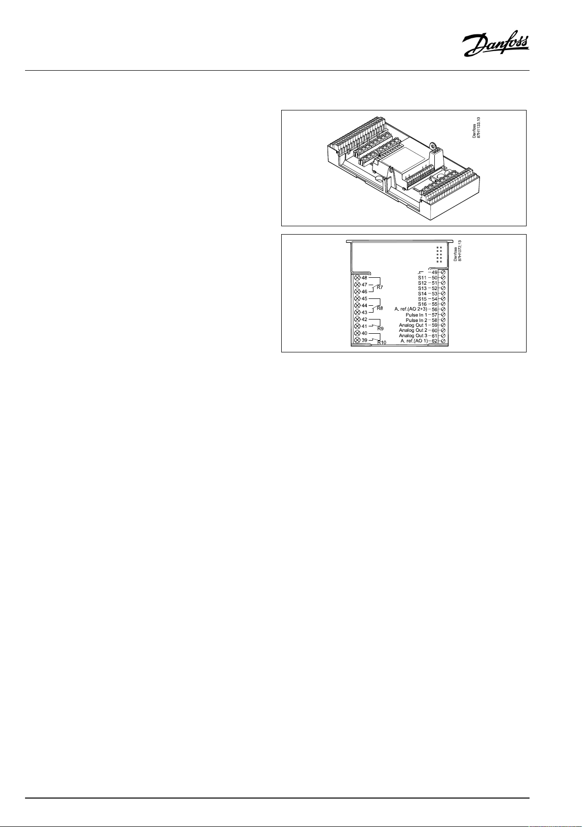
OperatingGuideECLComfort210/296/310,applicationA232/A332
Thecommongroundterminalisusedforconnectionofrelevant
components(pumps,motorizedcontrolvalves).
ECL210/310
ECL296
Maximumloadratings:
Relayterminals
Triac(=electronic
relay)terminals
Wirecrosssection:0.5-1.5mm²
Incorrectconnectioncandamagetheelectronicoutputs.
Max.2x1.5mm²wirescanbeinsertedintoeachscrewterminal.
4(2)A/230Va.c.
(4Aforohmicload,2Afor
inductiveload)
0,2A/230Va.c.
28|©Danfoss|2021.06
AQ150486469826en-010501
Page 29
OperatingGuideECLComfort210/296/310,applicationA232/A332
2.5.2Electricalconnections,Pt1000temperaturesensors
SeealsotheInstallationGuide(deliveredwiththeapplicationkey)
forapplicationspecificconnections.
AQ150486469826en-010501
©Danfoss|2021.06|29
Page 30
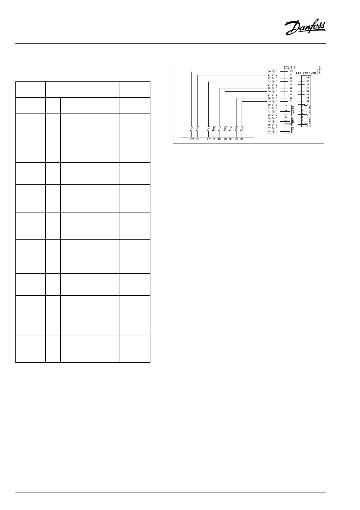
OperatingGuideECLComfort210/296/310,applicationA232/A332
ConnectionsforA232,ingeneral:
SeealsotheInstallationGuide(deliveredwiththeapplicationkey)
forapplicationspecificconnections.
TerminalSensor/description
29and30
28and30
27and30
26and30
25and30
24and30
23and30
22and30
21and30
20and30
S1
Outdoortemperature
sensor*
S2Roomtemperature
sensor.
Alternative:ECA31
S3
Flowtemperature
sensor**
S4
A332.2andA332.3
only:Flowtemperature
sensor,cooling**
S5
Surfaceorreturn
temperaturesensor
S6
Surfaceorreturn
temperaturesensor
S7
Overridesignal.
A332.3only:Supply
temperaturesensor
S8
Overridesignal.
A332.3only:DHWflow
switch
S9
ECL310only:
A332.2:Return
temperaturesensor.
A332.3:DHWflow
temperaturesensor**
A332.4:Overridesignal
S10
ECL310only:
Returntemperature
sensor
Type
(recom.)
ESMT
ESM-10
ESM-11/
ESMB/
ESMC/
ESMU
ESMC/
ESMU
ESM-11/
ESMB/
ESMC/
ESMU
ESM-11/
ESMB/
ESMC/
ESMU
Switch.
ESM-11/
ESMB/
ESMC/
ESMU
Switch
ESM-11/
ESMB/
ESMC/
ESMU.
Switch
ESM-11/
ESMB/
ESMC/
ESMU
Temperaturesensorsmustbeconnectedinordertohavethe
desiredfunctionality.
*
Iftheoutdoortemperaturesensorisnotconnectedorthe
sensorcableisshort-circuited,thecontrollerassumesthat
theoutdoortemperatureis0(zero)°C.
**
Ifthesensorisnotconnectedorthesensorcableis
short-circuited,themotorizedcontrolvalvecloses(safety
function).
Factoryestablishedjumper:
30tocommonterminal.
30|©Danfoss|2021.06
AQ150486469826en-010501
Page 31

OperatingGuideECLComfort210/296/310,applicationA232/A332
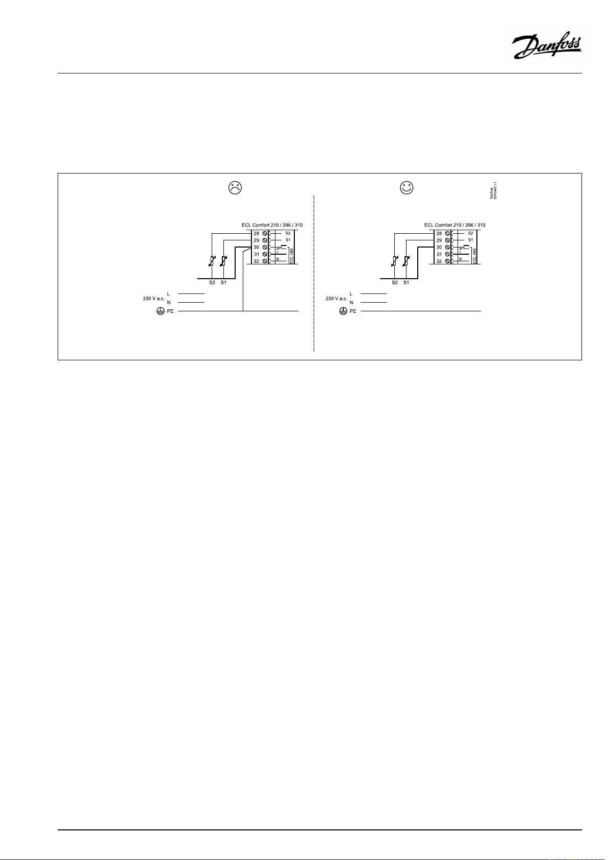
Overridecontacts/switches:
Exampleofoverridecontact,connectedtoS7:
Wirecrosssection:0.5-1.5mm²
Incorrectconnectioncandamagetheelectronicoutputs.
Max.2x1.5mm²wirescanbeinsertedintoeachscrewterminal.
Connectionofswitchforexternaloverride
Wirecrosssectionforsensorconnections:Min.0.4mm².
Totalcablelength:Max.200m(allsensorsincl.internalECL485
communicationbus).
Cablelengthsofmorethan200mmaycausenoisesensibility(EMC).
AQ150486469826en-010501
©Danfoss|2021.06|31
Page 32

OperatingGuideECLComfort210/296/310,applicationA232/A332
2.5.3Electricalconnections,ECA30/31
Terminal
ECL
Terminal
ECA30/31
30
31
4
1
322
333
4
5
*
Afteranexternalroomtemperaturesensorhasbeenconnected,
Description
Twistedpair
Twistedpair
Ext.roomtemperature
sensor*
Type
(recomm.)
Cable2x
twistedpair
ESM-10
ECA30/31mustberepowered.
ThecommunicationtotheECA30/31mustbesetupintheECL
Comfortcontrollerin'ECAaddr.'
TheECA30/31mustbesetupaccordingly.
AfterapplicationsetuptheECA30/31isreadyafter2–5min.A
progressbarintheECA30/31isdisplayed.
Iftheactualapplicationcontainstwoheatingcircuits,itispossible
toconnectanECA30/31toeachcircuit.Theelectricalconnections
aredoneinparallel.
Max.2ECA30/31canbeconnectedtoanECLComfort310controller
ortoECLComfort210/296/310controllersinamaster-slavesystem.
SetupproceduresforECA30/31:Seesection‘Miscellaneous’ .
ECAinformationmessage:
‘Applicationreq.newerECA’:
Thesoftware(firmware)ofyourECAdoesnotcomplywiththe
software(firmware)ofyourECLComfortcontroller.Pleasecontact
yourDanfosssalesoffice.
Someapplicationsdonotcontainfunctionsrelatedtoactualroom
temperature.TheconnectedECA30/31willonlyfunctionasremote
control.
32|©Danfoss|2021.06
AQ150486469826en-010501
Page 33

OperatingGuideECLComfort210/296/310,applicationA232/A332
Totalcablelength:Max.200m(allsensorsincl.internalECL485
communicationbus).
Cablelengthsofmorethan200mmaycausenoisesensibility(EMC).
AQ150486469826en-010501
©Danfoss|2021.06|33
Page 34

OperatingGuideECLComfort210/296/310,applicationA232/A332
2.5.4Electricalconnections,master/slavesystems
Thecontrollercanbeusedasmasterorslaveinmaster/slave
systemsviatheinternalECL485communicationbus(2xtwisted
paircable).
TheECL485communicationbusisnotcompatiblewiththeECL
businECLComfort110,200,300and301!
Terminal
Description
Type
(recomm.)
30
Commonterminal
+12V*,ECL485communicationbus
31
*OnlyforECA30/31andmaster/
slavecommunication
32
B,ECL485communicationbus
33
A,ECL485communicationbus
Cable2x
twistedpair
Totalcablelength:Max.200m(allsensorsincl.internalECL485
communicationbus).
Cablelengthsofmorethan200mmaycausenoisesensibility(EMC).
ECL485buscable
MaximumrecommendedlengthoftheECL485busiscalculatedlike
this:
Subtract"TotallengthofallinputcablesofallECLcontrollersinthe
master-slavesystem"from200m.
2.5.5Electricalconnections,communication
Electricalconnections,Modbus
ECLComfort210:Non-galvanicisolatedModbusconnections
ECLComfort296:GalvanicisolatedModbusconnections
ECLComfort310:GalvanicisolatedModbusconnections
Simpleexamplefortotallengthofallinputcables,3xECL:
1xECL
3xECL
3xECLReturntemp.sensor:
3xECLRoomtemp.sensor:
Total:
MaximumrecommendedlengthoftheECL485bus:
200-81m=119m
Outdoortemp.sensor:
Flowtemp.sensor:
15m
18m
18m
30m
81m
34|©Danfoss|2021.06
AQ150486469826en-010501
Page 35

OperatingGuideECLComfort210/296/310,applicationA232/A332
2.5.6Electricalconnections,communication
Electricalconnections,M-bus
ECLComfort210:Notimplemented
ECLComfort296:Onboard,non-galvanicisolated.Max.cable
length50m.
ECLComfort310:Onboard,non-galvanicisolated.Max.cable
length50m.
AQ150486469826en-010501
©Danfoss|2021.06|35
Page 36

OperatingGuideECLComfort210/296/310,applicationA232/A332
2.6InsertingtheECLApplicationKey
2.6.1InsertingtheECLApplicationKey
TheECLApplicationKeycontains
•theapplicationanditssubtypes,
•currentlyavailablelanguages,
•factorysettings:e.g.schedules,desiredtemperatures,
limitationvaluesetc.Itisalwayspossibletorecoverthefactory
settings,
•memoryforusersettings:specialuser/systemsettings.
Afterhavingpowered-upthecontroller,differentsituationsmight
beexisting:
1.Thecontrollerisnewfromthefactory,theECLApplicationKey
isnotinserted.
2.Thecontrolleralreadyrunsanapplication.TheECLApplication
Keyisinserted,buttheapplicationneedstobechanged.
3.Acopyofthecontrollerssettingsisneededforconfiguring
anothercontroller.
ECLComfort210/310
ECLComfort210/310
Usersettingsare,amongothers,desiredroomtemperature,desired
DHWtemperature,schedules,heatcurve,limitationvaluesetc.
Systemsettingsare,amongothers,communicationset-up,display
brightnessetc.
36|©Danfoss|2021.06
ECLComfort296
AQ150486469826en-010501
Page 37

OperatingGuideECLComfort210/296/310,applicationA232/A332
Automaticupdateofcontrollersoftware(firmware):
Thesoftwareofthecontrollerisupdatedautomaticallywhenthekey
isinserted(asofcontrollerversion1.11(ECL210/310)andversion
1.58(ECL296)).Thefollowinganimationwillbeshownwhenthe
softwareisbeingupdated:
Progressbar
Duringupdate:
•DonotremovetheKEY
Ifthekeyisremovedbeforethehour-glassisshown,youhave
tostartafresh.
•Donotdisconnectthepower
Ifthepowerisinterruptedwhenthehour-glassisshown,the
controllerwillnotwork.
•Manualupdateofcontrollersoftware(firmware):
Seethesection"Automatic/manualupdateoffirmware"
The“Keyoverview”doesnotinform—throughECA30/31—about
thesubtypesoftheapplicationkey.
Keyinserted/notinserted,description:
ECLComfort210/310,controllerversionslowerthan1.36:
-
Takeouttheapplicationkey;for20minutes
settingscanbechanged.
-
Powerupthecontrollerwithoutthe
applicationkeyinserted;for20minutes
settingscanbechanged.
ECLComfort210/310,controllerversions1.36andup:
-
Takeouttheapplicationkey;for20minutes
settingscanbechanged.
-
Powerupthecontrollerwithoutthe
applicationkeyinserted;settingscannotbe
changed.
ECLComfort296,controllerversions1.58andup:
-
Takeouttheapplicationkey;for20minutes
settingscanbechanged.
-
Powerupthecontrollerwithoutthe
applicationkeyinserted;settingscannotbe
changed.
AQ150486469826en-010501
©Danfoss|2021.06|37
Page 38

OperatingGuideECLComfort210/296/310,applicationA232/A332
ApplicationKey:Situation1
Thecontrollerisnewfromthefactory,theECLApplicationKey
isnotinserted.
AnanimationfortheECLApplicationKeyinsertionisdisplayed.
InserttheApplicationKey.
ApplicationKeynameandVersionisindicated(example:A266
Ver.1.03).
IftheECLApplicationKeyisnotsuitableforthecontroller,a"cross"
isdisplayedovertheECLApplicationKey-symbol.
Action:Purpose:
Selectlanguage
Confirm
Selectapplication(subtype)
Somekeyshaveonlyoneapplication.
Confirmwith‘Yes’
Set'Time&Date'
Turnandpushthedialtoselectand
change'Hours' ,'Minutes' ,'Date' ,
'Month'and'Year' .
Choose''Next'
Confirmwith‘Yes’
Goto‘Aut.daylight’
Choosewhether‘ Aut.daylight´*
shouldbeactiveornot
*‘Aut.daylight’istheautomaticchangeoverbetweensummer
andwintertime.
DependingonthecontentsoftheECLApplicationKey,procedure
AorBistakingplace:
A
TheECLApplicationkeycontainsfactorysettings:
Thecontrollerreads/transfersdatafromtheECLApplicationKey
toECLcontroller.
Examples:
YESorNO
Theapplicationisinstalled,andthecontrollerresetsandstartsup.
B
TheECLApplicationkeycontainschangedsystemsettings:
Pushthedialrepeatedly.
’NO’:
’YES*:
Ifthekeycontainsusersettings:
Pushthedialrepeatedly.
‘NO:
‘YES*:
*If‘YES’cannotbechosen,theECLApplicationKeydoesnot
containanyspecialsettings.
Choose‘Startcopying’andconfirmwith'Yes'.
38|©Danfoss|2021.06
OnlyfactorysettingsfromtheECLApplicationKeywill
becopiedtothecontroller.
Specialsystemsettings(differingfromthefactory
settings)willbecopiedtothecontroller.
OnlyfactorysettingsfromtheECLApplicationKeywill
becopiedtothecontroller.
Specialusersettings(differingfromthefactorysettings)
willbecopiedtothecontroller.
AQ150486469826en-010501
Page 39

OperatingGuideECLComfort210/296/310,applicationA232/A332
(Example):
The"i"intheupperrightcornerindicatesthat-besidesthefactory
settings-thesubtypealsocontainsspecialuser/systemssettings.
ApplicationKey:Situation2
Thecontrolleralreadyrunsanapplication.TheECLApplication
Keyisinserted,buttheapplicationneedstobechanged.
TochangetoanotherapplicationontheECLApplicationKey,the
currentapplicationinthecontrollermustbeerased(deleted).
BeawarethattheApplicationKeymustbeinserted.
Action:Purpose:
Choose‘MENU’inanycircuit
Confirm
Choosethecircuitselectoratthetop
rightcornerinthedisplay
Confirm
Choose‘Commoncontrollersettings’
Confirm
Choose‘Keyfunctions’
Confirm
Choose‘Eraseapplication’
Confirmwith‘Yes’
Thecontrollerresetsandisreadytobeconfigured.
Followtheproceduredescribedinsituation1.
Examples:
AQ150486469826en-010501
©Danfoss|2021.06|39
Page 40

OperatingGuideECLComfort210/296/310,applicationA232/A332
ApplicationKey:Situation3
Acopyofthecontrollerssettingsisneededforconfiguring
anothercontroller.
Thisfunctionisused
•forsaving(backup)ofspecialuserandsystemsettings
•whenanotherECLComfortcontrollerofthesametype(210,
296or310)mustbeconfiguredwiththesameapplicationbut
user/systemsettingsdifferfromthefactorysettings.
HowtocopytoanotherECLComfortcontroller:
Action:Purpose:
Choose‘MENU’
Confirm
Choosethecircuitselectoratthetop
rightcornerinthedisplay
Confirm
Choose'Commoncontrollersettings'
Confirm
Goto‘Keyfunctions’
Confirm
Choose‘Copy’
Confirm
Choose‘To’ .
‘ECL’or‘KEY’willbeindicated.Choose
’ECL’orKEY’
Pushthedialrepeatedlytochoose
copydirection
Choose‘Systemsettings’or‘User
settings’
Pushthedialrepeatedlytochoose
‘Yes’or‘No’in‘Copy’ .Pushtoconfirm.
Choose‘Startcopying’
TheApplicationKeyorthecontroller
isupdatedwithspecialsystemoruser
settings.
Examples:
*
’ECL’or‘KEY’ .
**
‘NO’or‘YES’
*
‘ECL’:
‘KEY’:
**
‘NO’:
‘YES’:
40|©Danfoss|2021.06
DatawillbecopiedfromtheApplicationKeytothe
ECLController.
DatawillbecopiedfromtheECLControllertothe
ApplicationKey.
ThesettingsfromtheECLcontrollerwillnotbecopied
totheApplicationKeyortotheECLComfortcontroller.
Specialsettings(differingfromthefactorysettings)will
becopiedtotheApplicationKeyortotheECLComfort
controller.IfYEScannotbechosen,therearenospecial
settingstobecopied.
AQ150486469826en-010501
Page 41

OperatingGuideECLComfort210/296/310,applicationA232/A332
Language
Atapplicationupload,alanguagemustbeselected.*
IfanotherlanguagethanEnglishisselected,theselectedlanguage
ANDEnglishwillbeuploadedintotheECLcontroller.
ThismakesserviceeasyforEnglishspeakingservicepeople,just
becausetheEnglishlanguagemenuscanbevisiblebychanging
theactualsetlanguageintoEnglish.
(Navigation:MENU>Commoncontroller>System>Language)
Iftheuploadedlanguageisnotsuitable,theapplicationmustbe
erased.UserandSystemsettingscanbesavedontheapplication
keybeforeerasing.
Afternewuploadwithpreferredlanguage,theexistingUserand
Systemsettingscanbeuploaded.
*)
(ECLComfort310,24Volt)Iflanguagecannotbeselected,the
powersupplyisnota.c.(alternatingcurrent).
2.6.2ECLApplicationKey,copyingdata
Generalprinciples
Whenthecontrollerisconnectedandoperating,youcancheck
andadjustallorsomeofthebasicsettings.Thenewsettingscan
bestoredontheKey.
Factorysettingscanalwaysberestored.
HowtoupdatetheECLApplicationKeyaftersettingshave
beenchanged?
AllnewsettingscanbestoredontheECLApplicationKey.
Howtostorefactorysettinginthecontrollerfromthe
ApplicationKey?
PleasereadtheparagraphconcerningApplicationKey,Situation
1:Thecontrollerisnewfromthefactory,theECLApplicationKey
isnotinserted.
HowtostorepersonalsettingsfromthecontrollertotheKey?
PleasereadtheparagraphconcerningApplicationKey,Situation3:
Acopyofthecontrollerssettingsisneededforconfiguringanother
controller
Asamainrule,theECLApplicationKeyshouldalwaysremainin
thecontroller.IftheKeyisremoved,itisnotpossibletochange
settings.
Makeanoteofnewsettingsinthe'Settingsoverview'table.
DonotremovetheECLApplicationKeywhilecopying.Thedataon
theECLApplicationKeycanbedamaged!
ItispossibletocopysettingsfromoneECLComfortcontrollerto
anothercontrollerprovidedthatthetwocontrollersarefromthesame
series(210or310).
Furthermore,whentheECLComfortcontrollerhasbeenuploaded
withanapplicationkey,minimumversion2.44,itispossibletoupload
personalsettingsfromapplicationkeys,minimumversion2.14.
AQ150486469826en-010501
©Danfoss|2021.06|41
Page 42

OperatingGuideECLComfort210/296/310,applicationA232/A332
The“Keyoverview”doesnotinform—throughECA30/31—about
thesubtypesoftheapplicationkey.
Keyinserted/notinserted,description:
ECLComfort210/310,controllerversionslowerthan1.36:
-
-
ECLComfort210/310,controllerversions1.36andup:
-
-
ECLComfort296,controllerversions1.58andup:
-
-
Takeouttheapplicationkey;for20minutes
settingscanbechanged.
Powerupthecontrollerwithoutthe
applicationkeyinserted;for20minutes
settingscanbechanged.
Takeouttheapplicationkey;for20minutes
settingscanbechanged.
Powerupthecontrollerwithoutthe
applicationkeyinserted;settingscannotbe
changed.
Takeouttheapplicationkey;for20minutes
settingscanbechanged.
Powerupthecontrollerwithoutthe
applicationkeyinserted;settingscannotbe
changed.
42|©Danfoss|2021.06
AQ150486469826en-010501
Page 43

OperatingGuideECLComfort210/296/310,applicationA232/A332
2.7Checklist
IstheECLComfortcontrollerreadyforuse?
Makesurethatthecorrectpowersupplyisconnectedtoterminals9and10(230Vor24V).
Makesurethecorrectphaseconditionsareconnected:
230V:Live=terminal9andNeutral=terminal10
24V:SP=terminal9andSN=terminal10
Checkthattherequiredcontrolledcomponents(actuator,pumpetc.)areconnectedtothecorrectterminals.
Checkthatallsensors/signalsareconnectedtothecorrectterminals(see'Electricalconnections').
Mountthecontrollerandswitchonthepower.
IstheECLApplicationKeyinserted(see'InsertingtheApplicationKey').
DoestheECLComfortcontrollercontainanexistingapplication(see'InsertingtheApplicationKey').
Isthecorrectlanguagechosen(see'Language'in'Commoncontrollersettings').
Isthetime&datesetcorrectly(see'Time&Date'in'Commoncontrollersettings').
Istherightapplicationchosen(see'Identifyingthesystemtype').
Checkthatallsettingsinthecontroller(see'Settingsoverview')aresetorthatthefactorysettingscomplywithyour
requirements.
Choosemanualoperation(see'Manualcontrol').Checkthatvalvesopenandclose,andthatrequiredcontrolled
components(pumpetc.)startandstopwhenoperatedmanually.
Checkthatthetemperatures/signalsshowninthedisplaymatchtheactualconnectedcomponents.
Havingcompletedthemanualoperationcheck,choosecontrollermode(scheduled,comfort,savingorfrostprotection).
AQ150486469826en-010501
©Danfoss|2021.06|43
Page 44

OperatingGuideECLComfort210/296/310,applicationA232/A332
2.8Navigation,ECLApplicationKeyA232/A332
Navigation,A232,applicationA232.1,heating
Home
MENU
ScheduleSchedule
Settings
Sub-menu
Flow
temperature
Roomlimit
Surfacelimit
Optimization
Controlpar.
Application
IDno.
11178
11177
11182
11183
11015
11060
11062
11061
11011
11012
11014
11026
11020
11021
11179
11174
11184
11185
11186
11187
11189
11024
11010
11500
11022
11023
11154
11153
11077
11078
11040
11093
11141
11142
11498
Function
Heatcurve
Temp.max.
Temp.min.
Infl.-max.
Infl.-min.
Adapt.time
Limit
Infl.–max.
Adapt.time
Autosaving
Boost
Optimizer
Pre-stop
Basedon
Totalstop
Summer,cut-out
Motorpr.
Xp
Tn
Mrun
Nz
Min.act.time
Actuator
ECAaddr.
SenddesiredT
Pexercise
Mexercise
Filt.acc.outd.T
Filt.acc.roomT
PfrostT
PheatT
Ppost-run
Frostpr.T
Ext.input
Ext.mode
Toutdepend.
A232
A232.1
(
(
(
(
(
(
(
(
(
(
(
(
(
(
(
(
(
(
(
(
(
(
(
(
(
(
(
(
(
(
(
(
(
(
(
(
(
44|©Danfoss|2021.06
AQ150486469826en-010501
Page 45

OperatingGuideECLComfort210/296/310,applicationA232/A332
Navigation,A232,applicationA232.1,heatingcontinued
Home
MENU
ScheduleSchedule
Settings
HolidaySelectable
Alarm
InfluenceoverviewDes.flowT
Sub-menu
IDno.
Optional
function
Temp.monitor.
Max.temp.
AlarmoverviewClearalarm
11089
11160
11158
11159
11038
11147
11148
11149
11150
11079
11080
Function
Acc.outputfunc.
Humidistat,setp.
Humidistat,diff.
Humidistat,postt.
StopatTout
Upperdifference
Lowerdifference
Delay
Lowesttemp.
Max.flowT
Delay
Max.temp.
Temp.monitor.
Tsensordefect
Roomlim.
Surfacelimit
Holiday
Ext.override
ECAoverride
Boost
SCADAoffset
Ext.stopcmd
A232
A232.1
(
(
(
(
(
(
(
(
(
(
(
(
(
(
(
(
(
(
(
(
(
(
(
(
(
AQ150486469826en-010501
©Danfoss|2021.06|45
Page 46

OperatingGuideECLComfort210/296/310,applicationA232/A332
Navigation,A232,applicationA232.1,cooling
Home
MENU
ScheduleSchedule
Settings
HolidaySelectable
Alarm
InfluenceoverviewDes.flowT
Sub-menu
IDno.
FlowtemperatureCoolcurve
12178
12177
12164
Roomlimit
Surfacelimit
Application
Temp.monitor.
AlarmoverviewClearalarm
12182
12183
12015
12157
12027
12060
12063
12061
12144
11179
12500
12092
12141
12142
12147
12148
12149
12150
Function
Temp.max.
Temp.min.
Dewp.Toffset
Infl.-max.
Infl.-min.
Adapt.time
RoomTinfluence
RoomTdiff.
Limit
Infl.–min.
Adapt.time
Activation,acc.T
Summer,cut-out
SenddesiredT
StandbyT
Ext.input
Ext.mode
Upperdifference
Lowerdifference
Delay
Lowesttemp.
Max.temp.
Temp.monitor.
Tsensordefect
Roomlim.
Surfacelimit
Holiday
SCADAoffset
Ext.stopcmd
A232
A232.1
(
(
(
(
(
(
(
(
(
(
(
(
(
(
(
(
(
(
(
(
(
(
(
(
(
(
(
(
(
(
(
(
(
46|©Danfoss|2021.06
AQ150486469826en-010501
Page 47

OperatingGuideECLComfort210/296/310,applicationA232/A332
Navigation,A232.1,Commoncontrollersettings
Home
MENU
Time&Date
ScheduleSelectable
Inputoverview
Log1
Log2
Outputoverride
Keyfunctions
OutdoorTLogtoday
FlowT&desiredLogyesterday
RoomT&desiredLog2days
Surf.Theat&des.
FlowT&desiredLogtoday
RoomT&desiredLogyesterday
Surf.Tcool&des.
HumidityLog4days
NewapplicationEraseapplication
Application
FactorysettingSystemsettings
Copy
Keyoverview
IDno.
Commoncontrollersettings
Function
Selectable
OutdoorT
Outdooracc.T
RoomT
Roomacc.T
FlowT
Surf.T,heat
Surf.T,cool
Humidity
DewpointT
Ext.stopcmd
Log4days
Log2days
M1
P1
M2
X2
X3
X4
Usersettings
Gotofactory
To
Systemsettings
Usersettings
Startcopying
AQ150486469826en-010501
©Danfoss|2021.06|47
Page 48

OperatingGuideECLComfort210/296/310,applicationA232/A332
Navigation,A232.1,Commoncontrollersettingscontinued
Home
MENU
SystemECLversion
Extension
Ethernet(ECLComfort310only)
Portalconfig(ECLComfort310only)
M-busconfig(ECLComfort310only)
EnergyMeters
(ECLComfort310only)
Rawinputoverview
Alarm
Display
Communication
Language
IDno.
Commoncontrollersettings
Function
Codeno.
Hardware
Software
Serialno.
Productiondate
Addresstype
ECLportal
Portalstatus
Portalinfo
5998
Command
5997
Baud
6000
M-busaddress
6002
Scantime
6001
Type
EnergyMeter1....5
S1-S8(ECLComfort210)
S1-S10(ECLComfort310)
S1-S18(ECLComfort310withECA32)
32:
Tsensordefect
60058
Backlight
60059
Contrast
2048
ECL485addr.
38
Modbusaddr.
39
Baud
2150
Servicepin
2151
Ext.reset
2050
Language
48|©Danfoss|2021.06
AQ150486469826en-010501
Page 49

OperatingGuideECLComfort210/296/310,applicationA232/A332
Navigation,A332,applicationsA332.1,A332.2,A332.3,A332.4,heating
Home
MENU
ScheduleSelectable
Settings
FlowtemperatureHeatcurve((((
Roomlimit
Returnlimit
Surfacelimit
Optimization
Controlpar.
IDno.
11178
11177
11182Infl.-max.((((
11183
11015
11031
11032
11033
11034
11035
11036
11037
11003
11060
11062
11061
12003
11011
11012
11014
11026
11020
11021
11179
11174
11184
11185
11186
11187
11189
11024
ApplicationsA332
Function
Temp.max.((((
Temp.min.
Infl.-min.((((
Adapt.time((((
HighToutX1((((
LowlimitY1((((
LowToutX2((((
HighlimitY2
Infl.–max.
Infl.–min.
Adapt.time
Circuit,sensor(
Limit
Infl.–max.
Adapt.time
Circuit,sensor(
Autosaving
Boost((((
Optimizer((((
Pre-stop((((
Basedon
Totalstop
Summer,cut-out((((
Motorpr.
Xp((((
Tn((((
Mrun((((
Nz((((
Min.act.time((((
Actuator((((
A332.1A332.2A332.3A332.4
(((
((((
((((
((((
((((
((((
((((
((((
((((
((((
((((
((((
(
AQ150486469826en-010501
©Danfoss|2021.06|49
Page 50

OperatingGuideECLComfort210/296/310,applicationA232/A332
Navigation,A332,applicationsA332.1,A332.2,A332.3,A332.4,heatingcontinued
Home
MENU
Settings
HolidaySelectable
Alarm
Application
Optionalfunction
Temp.monitor.
Max.temp.
AlarmoverviewClearalarm
IDno.
11010
11500
11022
11023
11154
11153
11077
11078
11040
11093
11141
11142
11498
11089
11160
11158
11159
11038
11083
11147
11148
11149
11150
11079
11080
ApplicationsA332
Function
ECAaddr.((((
SenddesiredT((((
Pexercise((((
Mexercise((((
Filt.acc.outd.T((((
Filt.acc.roomT((((
PfrostT((((
PheatT((((
Ppost-run((((
Frostpr.T((((
Ext.input((((
Ext.mode
Toutdepend.
Acc.outputfunc.
Humidistat,setp.
Humidistat,diff.
Humidistat,postt.
StopatTout((((
Add.function
Upperdifference
Lowerdifference
Delay
Lowesttemp.((((
Max.flowT
Delay
Max.temp.((((
Temp.monitor.((((
Tsensordefect((((
A332.1A332.2A332.3A332.4
((((
((((
((((
((((
((((
((((
((((
((((
((((
((((
((((
((((
((((
((((
50|©Danfoss|2021.06
AQ150486469826en-010501
Page 51

OperatingGuideECLComfort210/296/310,applicationA232/A332
Navigation,A332,applicationsA332.1,A332.2,A332.3,A332.4,heatingcontinued
Home
MENU
InfluenceDes.flowT
overview
IDno.
ApplicationsA332
Function
Returnlim.
Roomlim.((((
Surfacelimit((((
Holiday((((
Ext.override((((
ECAoverride((((
Boost((((
SCADAoffset((((
Ext.stopcmd(((
Ext.ONcmd(
A332.1A332.2A332.3A332.4
((((
AQ150486469826en-010501
©Danfoss|2021.06|51
Page 52

OperatingGuideECLComfort210/296/310,applicationA232/A332
Navigation,A332,applicationsA332.1,A332.2,A332.3,A332.4,cooling
Home
MENU
ScheduleSelectable
Settings
FlowtemperatureCoolcurve((((
Roomlimit
Returnlimit
Surfacelimit
Controlpar.
IDno.
12178
12177
12164
12182Infl.-max.((((
12183
12015
12157
12027
12030
12035
12036
12037
13003
12060
12063
12061
14003
12174
12184
12185
12186
12187
12189
12024
ApplicationsA332
Function
Temp.max.((((
Temp.min.
Dewp.Toffset
Infl.-min.((((
Adapt.time((((
RoomTinfluence((((
RoomTdiff.((((
Limit
Infl.–max.
Infl.–min.
Adapt.time
Circuit,sensor(
Limit
Infl.–min.
Adapt.time
Circuit,sensor(
Motorpr.
Xp((
Tn((
Mrun((
Nz((
Min.act.time((
Actuator((
A332.1A332.2A332.3A332.4
(((
(((
((((
((((
((((
((((
((((
((((
((((
((
(
(
52|©Danfoss|2021.06
AQ150486469826en-010501
Page 53

OperatingGuideECLComfort210/296/310,applicationA232/A332
Navigation,A332,applicationsA332.1,A332.2,A332.3,A332.4,coolingcontinued
Home
MENU
Settings
HolidaySelectable
Alarm
InfluenceDes.flowT
overview
Application
Temp.monitor.
AlarmoverviewClearalarm
IDno.
12156
12144
11179
12500
12022
12023
12070
12040
12092
12141
12142
12147
12148
12149
12150
ApplicationsA332
Function
Act.,acc.roomT
Activation,acc.T((((
Summer,cut-out((((
SenddesiredT((((
Pexercise((
Mexercise((
PcoolT((
Ppost-run((
StandbyT((((
Ext.input((((
Ext.mode
Upperdifference
Lowerdifference
Delay
Lowesttemp.((((
Temp.monitor.((((
Tsensordefect
Returnlim.
Roomlim.
Surfacelimit
Holiday
SCADAoffset
Ext.stopcmd
Ext.ONcmd
A332.1A332.2A332.3A332.4
((((
((((
((((
((((
((((
((((
((((
((((
((((
((((
((((
((((
((((
(((
(
AQ150486469826en-010501
©Danfoss|2021.06|53
Page 54

OperatingGuideECLComfort210/296/310,applicationA232/A332
Navigation,A332,applicationA332.3,DHW
Home
MENU
ScheduleSchedule
Schedulecirc.PSchedule
Settings
HolidaySelectable
Alarm
InfluenceoverviewDes.flowT
Sub-menu
IDno.
Flowtemperature
Returnlimit
Controlpar.
Application
Anti-bacteriaSelectable
Temp.monitor.
AlarmoverviewClearalarm
13178
13177
13030
13035
13036
13037
13085
13173
13174
13185
13186
13187
13189
13097
13096
13094
13095
13500
13076
13040
13093
13141
13142
13147
13148
13149
13150
Function
Temp.max.
Temp.min.
Limit
Infl.-max.
Infl.-min.
Adapt.time
Priority
Autotuning
Motorpr.
Xpactual
Tn
Mrun
Nz
Min.act.time
SupplyT(idle)
Tn(idle)
Opentime
Closetime
SenddesiredT
Circ.PfrostT
Ppost-run
Frostpr.T
Ext.input
Ext.mode
Upperdifference
Lowerdifference
Delay
Lowesttemp.
Temp.monitor.
Tsensordefect
Returnlim.
Holiday
Ext.override
Anti-bacteria
SCADAoffset
A332
A332.3
(
(
(
(
(
(
(
(
(
(
(
(
(
(
(
(
(
(
(
(
(
(
(
(
(
(
(
(
(
(
(
(
(
(
(
(
(
(
(
(
54|©Danfoss|2021.06
AQ150486469826en-010501
Page 55

OperatingGuideECLComfort210/296/310,applicationA232/A332
Navigation,A332,applicationsA332.1,A332.2,A332.3,A332.4,Commoncontrollersettings
Home
MENU
Time&Date
ScheduleSelectable
HolidaySelectable
Inputoverview
Log1
Log2
LogtodayOutdoorT
LogyesterdayFlowT&desired
Log2daysRoomT&desired
Log4daysHeatreturnT&limi
LogtodayFlowT&desired
LogyesterdayRoomT&desired
Log2daysCoolreturnT
Log4days
IDno.
ApplicationsA332,Commoncontrollersettings
Function
Selectable
OutdoorT
Outdooracc.T
RoomT
Roomacc.T
FlowT
ReturnT
HeatflowT
HeatreturnT
Surf.T,heat
CoolflowT
CoolreturnT
Surf.T,cool
DHWflowT
DHWreturnT
SupplyT
Humidity
DewpointT
Ext.stopcmd
S7status
S9status
Surf.Theat&des.
Surf.Tcool&des.
Humidity
A332.1A332.2A332.3A332.4
((((
((((
(
((((
((((
((((
((((
((
((
((
((
((((
((
((
((((
(
(
(
((((
((((
((
(
(
((((
((((
((((
((((
((((
((((
((((
((((
((((
((((
AQ150486469826en-010501
©Danfoss|2021.06|55
Page 56

OperatingGuideECLComfort210/296/310,applicationA232/A332
Navigation,A332,applicationsA332.1,A332.2,A332.3,A332.4,Commoncontrollersettingscontinued
Home
MENU
Outputoverride
Keyfunctions
SystemECLversion
IDno.
NewapplicationEraseapplication
Application
FactorysettingSystemsettings
Copy
Keyoverview
Extension
Ethernet
Portalconfig
M-busconfig
EnergyMeters
Rawinputoverview
Alarm
Display
Communication
Language
60058
60059
2048
38
39
2150
2151
2050
Function
M1
P1
M2
P2
M3
P7
X2
X3
X4
X5
A1
Usersettings
Gotofactory
To
Systemsettings
Usersettings
Startcopying
Codeno.
Hardware
Software
Buildno.
Serialno.
Productiondate
Tsensordefect
Backlight
Contrast
ECL485addr.
Modbusaddr.
Baud
Servicepin
Ext.reset
Language
ApplicationsA332,Commoncontrollersettings
A332.1A332.2A332.3A332.4
((((
((((
((((
((
(
(
((
((((
((((
((((
((((
((((
((((
((((
((((
((((
((((
((((
((((
((((
((((
((((
((((
((((
((((
((((
((((
((((
((((
((((
((((
((((
((((
((((
((((
((((
((((
((((
((((
((((
((((
((((
56|©Danfoss|2021.06
AQ150486469826en-010501
Page 57

OperatingGuideECLComfort210/296/310,applicationA232/A332
3.0Dailyuse
3.1Howtonavigate
Younavigateinthecontrollerbyturningthedialleftorrightto
thedesiredposition().
Thedialhasabuilt-inaccellerator.Thefasteryouturnthedial,the
fasteritreachesthelimitsofanywidesettingrange.
Thepositionindicatorinthedisplay(
youare.
Pushthedialtoconfirmyourchoices().
Thedisplayexamplesarefromatwo-circuitapplication:One
heatingcircuit()andonedomestichot-water(DHW)circuit().
Theexamplesmightdifferfromyourapplication.
)willalwaysshowyouwhere
ExampleshowsECL210/310
Heatingcircuit():DHWcircuit();
Somegeneralsettingswhichapplytotheentirecontrollerare
locatedinaspecificpartofthecontroller.
Toenter‘Commoncontrollersettings’:
Action:Purpose:
Choose‘MENU’inanycircuit
Confirm
Choosethecircuitselectoratthetop
rightcornerinthedisplay
Confirm
Choose‘Commoncontrollersettings’
Confirm
Examples:
Circuitselector
AQ150486469826en-010501
©Danfoss|2021.06|57
Page 58

OperatingGuideECLComfort210/296/310,applicationA232/A332
3.2Understandingthecontrollerdisplay
ThissectiondescribesthefunctioningeneralfortheECLComfort
210/296/310series.Theshowndisplaysaretypicalandnot
applicationrelated.Theymightdifferfromthedisplaysinyour
application.
Choosingafavoritedisplay
Yourfavoritedisplayisthedisplayyouhavechosenasthedefault
display.Thefavoritedisplaywillgiveyouaquickoverviewofthe
temperaturesorunitsthatyouwanttomonitoringeneral.
Ifthedialhasnotbeenactivatedfor20min.,thecontrollerwill
reverttotheoverviewdisplayyouhavechosenasfavorite.
Toshiftbetweendisplays:Turnthedialuntilyoureachthedisplay
selector(
turntochooseyourfavoriteoverviewdisplay.Pushthedialagain.
)atthebottomrightsideofthedisplay.Pushthedialand
Heatingcircuit
Overviewdisplay1informsabout:
actualoutdoortemperature,controllermode,
actualroomtemperature,desiredroomtemperature.
Overviewdisplay2informsabout:
actualoutdoortemperature,trendinoutdoortemperature,
controllermode,max.andmin.outdoortemperaturessince
midnightaswellasdesiredroomtemperature.
Overviewdisplay3informsabout:
date,actualoutdoortemperature,controllermode,time,desired
roomtemperatureaswellasshowsthecomfortscheduleofthe
currentday.
Overviewdisplay4informsabout:
stateofthecontrolledcomponents,actualflowtemperature,
(desiredflowtemperature),controllermode,returntemperature
(limitationvalue),influenceondesiredflowtemperature.
ThevalueabovetheV2symbolindicates0–100%oftheanalogue
signal(0–10V).
Note:
Anactualflowtemperaturevaluemustbepresent,otherwisethe
circuit'scontrolvalvewillclose.
Overviewdisplay1:Overviewdisplay2:
Overviewdisplay3:Overviewdisplay4:
Exampleofoverviewdisplaywith
Influenceindication:
Example,favoritedisplay1in
A230.3,wheremin.desiredroom
temperatureisindicated(22.7):
Dependentonthechosendisplay,theoverviewdisplaysforthe
heatingcircuitinformyouabout:
•actualoutdoortemperature(-0.5)
•controllermode()
•actualroomtemperature(24.5)
•desiredroomtemperature(20.7°C)
•trendinoutdoortemperature(
)
•min.andmax.outdoortemperaturessincemidnight(
•date(23.02.2010)
•time(7:43)
•comfortscheduleofthecurrentday(0-12-24)
•stateofthecontrolledcomponents(M2,P2)
•actualflowtemperature(49°C),(desiredflowtemperature(31))
•returntemperature(24°C)(limitationtemperature(50))
58|©Danfoss|2021.06
)
AQ150486469826en-010501
Page 59

OperatingGuideECLComfort210/296/310,applicationA232/A332
Thesettingofthedesiredroomtemperatureisimportantevenifa
roomtemperaturesensor/RemoteControlUnitisnotconnected.
Ifthetemperaturevalueisdisplayedas
"--"
thesensorinquestionisnotconnected.
"---"
thesensorconnectionisshort-circuited.
DHWcircuit
Overviewdisplay1informsabout:
actualDHWtemperature,controllermode,desiredDHW
temperatureaswellasthecomfortscheduleofthecurrentday.
Overviewdisplay2informsabout:
stateofthecontrolledcomponents,actualDHWtemperature,
(desiredDHWtemperature),controllermode,returntemperature
(limitationvalue),influenceondesiredDHWtemperature.
Dependentonchosendisplay,theoverviewdisplaysfortheDHW
circuitinformyouabout:
•actualDHWtemperature(50.3)
•controllermode(
)
•desiredDHWtemperature(50°C)
•comfortscheduleofthecurrentday(0-12-24)
•stateofthecontrolledcomponents(M1,P1)
•actualDHWtemperature(50°C),(desiredDHWtemperature(50))
•returntemperature(--°C)(limitationtemperature(30))
Settingthedesiredtemperature
Dependingonthechosencircuitandmode,itispossibletoenter
alldailysettingsdirectlyfromtheoverviewdisplays(seealsothe
nextpageconcerningsymbols).
Overviewdisplay1:Overviewdisplay2:
Exampleofoverviewdisplaywith
Influenceindication:
AQ150486469826en-010501
©Danfoss|2021.06|59
Page 60

OperatingGuideECLComfort210/296/310,applicationA232/A332
Settingthedesiredroomtemperature
Thedesiredroomtemperaturecaneasilybeadjustedinthe
overviewdisplaysfortheheatingcircuit.
Action:Purpose:
Desiredroomtemperature
Confirm
Adjustthedesiredroomtemperature
Confirm
Thisoverviewdisplayinformsaboutoutdoortemperature,actual
roomtemperatureaswellasdesiredroomtemperature.
Thedisplayexampleisforcomfortmode.Ifyouwanttochange
thedesiredroomtemperatureforsavingmode,choosethemode
selectorandselectsaving.
Examples:
20.5
21.0
Thesettingofthedesiredroomtemperatureisimportantevenifa
roomtemperaturesensor/RemoteControlUnitisnotconnected.
SettingthedesiredDHWtemperature
ThedesiredDHWtemperaturecaneasilybeadjustedinthe
overviewdisplaysfortheDHWcircuit.
Action:Purpose:
DesiredDHWtemperature
Confirm
AdjustthedesiredDHWtemperature
Confirm
InadditiontotheinformationaboutdesiredandactualDHW
temperature,thetoday'sscheduleisvisible.
Thedisplayexampleindicatesthatthecontrollerisinscheduled
operationandincomfortmode.
Examples:
50
55
60|©Danfoss|2021.06
AQ150486469826en-010501
Page 61

OperatingGuideECLComfort210/296/310,applicationA232/A332
Settingthedesiredroomtemperature,ECA30/ECA31
Thedesiredroomtemperaturecanbesetexactlyasinthe
controller.However,othersymbolscanbepresentinthedisplay
(pleasesee'Whatdothesymbolsmean?').
WiththeECA30/ECA31youcanoverridethedesiredroom
temperaturesetinthecontrollertemporarilybymeansoftheoverride
functions:
AQ150486469826en-010501
©Danfoss|2021.06|61
Page 62

OperatingGuideECLComfort210/296/310,applicationA232/A332
3.3Ageneraloverview:Whatdothesymbolsmean?
Symbol
Description
Outdoortemp.
Relativehumidityindoor
Roomtemp.
DHWtemp.
Positionindicator
Scheduledmode
Comfortmode
Savingmode
Frostprotectionmode
Manualmode
Standby
Coolingmode
Symbol
Temperature
Mode
Description
Alarm
Letter
Event
Monitoringtemperaturesensor
connection
Displayselector
Max.andmin.value
Trendinoutdoortemperature
Windspeedsensor
Sensornotconnectedornotused
Sensorconnectionshort-circuited
Fixedcomfortday(holiday)
Activeinfluence
Heatingactive(+)
Coolingactive(-)
Activeoutputoverride
Optimizedstartorstoptime
Heating
Cooling
DHW
Commoncontrollersettings
PumpON
PumpOFF
FanON
FanOFF
Actuatoropens
Actuatorcloses
Actuator,analoguecontrol
signal
Pump/fanspeed
DamperON
Circuit
Controlled
component
Numberofheatexchangers
Additionalsymbols,ECA30/31:
Symbol
InECA30/31onlythesymbolsthatarerelevanttotheapplicationin
thecontrolleraredisplayed.
Description
ECARemoteControlUnit
Connectionaddress(master:15,slaves:1-9)
15
Dayoff
Holiday
Relaxing(extendedcomfortperiod)
Goingout(extendedsavingperiod)
62|©Danfoss|2021.06
DamperOFF
AQ150486469826en-010501
Page 63

OperatingGuideECLComfort210/296/310,applicationA232/A332
3.4Monitoringtemperaturesandsystemcomponents
ThissectiondescribesthefunctioningeneralfortheECLComfort
210/296/310series.Theshowndisplaysaretypicalandnot
applicationrelated.Theymightdifferfromthedisplaysinyour
application.
Heatingcircuit
Theoverviewdisplayintheheatingcircuitensuresaquick
overviewoftheactualand(desired)temperaturesaswellasthe
actualstateofthesystemcomponents.
Displayexample:
49°C
(31)
24°C
(50)
DHWcircuit
TheoverviewdisplayintheDHWcircuitensuresaquickoverview
oftheactualand(desired)temperaturesaswellastheactualstate
ofthesystemcomponents.
Displayexample(heatexchanger):
50°C
(50)
(30)
Flowtemperature
Desiredflowtemperature
Returntemperature
Returntemperaturelimitation
Flowtemperature
Desiredflowtemperature
--
Returntemperature:sensornotconnected
Returntemperaturelimitation
Displayexamplewithheatexchanger:
Inputoverview
Anotheroptiontogetaquickoverviewofmeasuredtemperatures
isthe'Inputoverview'whichisvisibleinthecommoncontroller
settings(howtoenterthecommoncontrollersettings,see
‘Introductiontocommoncontrollersettings’ .)
Asthisoverview(seedisplayexample)onlystatesthemeasured
actualtemperatures,itisread-only.
AQ150486469826en-010501
©Danfoss|2021.06|63
Page 64

OperatingGuideECLComfort210/296/310,applicationA232/A332
3.5Influenceoverview
ThissectiondescribesthefunctioningeneralfortheECLComfort
210/296/310series.Theshowndisplaysaretypicalandnot
applicationrelated.Theymightdifferfromthedisplaysinyour
application.
Themenugivesanoverviewoftheinfluencesonthedesired
flowtemperature.Itdiffersfromapplicationtoapplicationwhich
parametersarelisted.Itcanbehelpfulinaservicesituationto
explainunexpectedconditionsortemperaturesamongothers.
Ifthedesiredflowtemperatureisinfluenced(corrected)byoneor
moreparameters,itisindicatedbyasmalllinewitharrow-down,
arrow-upordouble-arrow:
Arrow-down:
Theparameterinquestionreducesthedesiredflowtemperature.
Arrow-up:
Theparameterinquestionincreasesthedesiredflowtemperature.
Double-arrow:
Theparameterinquestioncreatesanoverride(e.g.Holiday).
Straightline:
Noactiveinfluence.
Intheexample,thearrowinthesymbolpointsdownwardsfor
'Roomlim. ' .Thismeansthattheactualroomtemperatureis
higherthanthedesiredroomtemperaturewhichagainresultsina
decreaseofthedesiredflowtemperature.
ExampleofoverviewdisplaywithInfluenceindication:
64|©Danfoss|2021.06
AQ150486469826en-010501
Page 65

OperatingGuideECLComfort210/296/310,applicationA232/A332
3.6Manualcontrol
ThissectiondescribesthefunctioningeneralfortheECLComfort
210/296/310series.Theshowndisplaysaretypicalandnot
applicationrelated.Theymightdifferfromthedisplaysinyour
application.
Itispossibletomanuallycontroltheinstalledcomponents.
Manualcontrolcanonlybeselectedinfavoritedisplaysinwhich
thesymbolsforthecontrolledcomponents(valve,pumpetc.)are
visible.
Action:Purpose:
Choosemodeselector
Confirm
Choosemanualmode
Confirm
Choosepump
Confirm
SwitchONthepump
SwitchOFFthepump.
Confirmpumpmode
Choosemotorizedcontrolvalve
Confirm
Openthevalve
Stopopeningthevalve
Closethevalve
Examples:
ControlledcomponentsCircuitselector
Duringmanualoperation:
•Allcontrolfunctionsaredeactivated
•Outputoverrideisnotpossible
•Frostprotectionisnotactive
Stopclosingthevalve
Confirmvalvemode
Toleavemanualcontrol,usethemodeselectortoselectthe
desiredmode.Pushthedial.
Manualcontrolistypicallyusedwhencommisioningthe
installation.Thecontrolledcomponents,valve,pumpetc.,canbe
controlledforcorrectfunction.
AQ150486469826en-010501
Whenmanualcontrolisselectedforonecircuit,itisautomatically
selectedforallcircuits!
©Danfoss|2021.06|65
Page 66

OperatingGuideECLComfort210/296/310,applicationA232/A332
3.7Schedule
3.7.1Setyourschedule
ThissectiondescribesthescheduleingeneralfortheECLComfort
210/296/310series.Theshowndisplaysaretypicalandnot
applicationrelated.Theymightdifferfromthedisplaysinyour
application.Insomeapplications,however,theremightbemore
thanoneschedule.Additionalschedulescanbefoundin‘Common
controllersettings’ .
Thescheduleconsistsofa7-dayweek:
=
M
Monday
=
T
Tuesday
=
W
Wednesday
=
T
Thursday
=
F
Friday
=
S
Saturday
=
S
Sunday
Theschedulewillday-by-dayshowyouthestartandstoptimesof
yourcomfortperiods(heating/DHWcircuits).
Changingyourschedule:
Action:
Purpose:
Choose'MENU'inanyoftheoverview
displays
Confirm
Confirmthechoice'Schedule'
Choosethedaytochange
Confirm*
GotoStart1
Confirm
Adjustthetime
Confirm
GotoStop1,Start2etc.etc.
Returnto'MENU'
Confirm
Choose'Yes'or'No'in'Save'
Confirm
Examples:
*Severaldayscanbemarked
Thechosenstartandstoptimeswillbevalidforallthechosendays
(inthisexampleThursdayandSaturday).
Youcansetmax.3comfortperiodsaday.Youcandeleteacomfort
periodbysettingstartandstoptimestothesamevalue.
66|©Danfoss|2021.06
Eachcircuithasitsownschedule.Tochangetoanothercircuit,goto
'Home',turnthedialandchoosethedesiredcircuit.
Thestartandstoptimescanbesetinhalf-hourly(30min.)intervals.
AQ150486469826en-010501
Page 67

OperatingGuideECLComfort210/296/310,applicationA232/A332
4.0Settingsoverview
Forfactorysettingsandsettingrange,seeappendix“ParameterIDoverview” .
ParametersindicatedwithanIDno.like"1x607"meanauniversalparameter.xstandsforcircuit/parametergroup.
SettingIDPage
Heatcurve
Xpactual
Day
Starttime
Duration
DesiredT
Circuit,sensor(functionalityofreturn/surfacetemperature
sensor)
Circuit,sensor(functionalityofreturn/surfacetemperature
sensor)
ECAaddr.(ECAaddress,choiceofRemoteControlUnit)
Autosaving(savingtemp.dependentonoutdoortemp.)
Boost
Optimizer(optimizingtimeconstant)
Adapt.time(adaptiontime)
Basedon(optimizationbasedonroom/outdoortemp.)
Totalstop
Pexercise(pumpexercise)
Mexercise(valveexercise)
Actuator
Pre-stop(optimizedstoptime)
RoomTdiff.(Roomtemperaturedifferenceforswitching
coolingmodeONandOFF)
Limit(returntemp.limitation)
HighToutX1(returntemp.limitation,highlimit,X-axis)
LowlimitY1(returntemp.limitation,lowlimit,Y-axis)
LowToutX2(returntemp.limitation,lowlimit,X-axis)
HighlimitY2(returntemp.limitation,highlimit,Y-axis)
Infl.-max.(returntemp.limitation-max.influence)
Infl.-min.(returntemp.limitation-min.influence)
Adapt.time(adaptationtime)
StopatTout(Stopfunctionrelatedtotheoutdoor
temperature)
Ppost-run
Limit(Limitationofsurfacetemperature)
Adapt.time(adaptationtime)
Infl.max(Influenceduringheatingmode)
Infl.min(Influenceduringcoolingmode)
PcoolT(coolingdemand)
Circ.PfrostT
1x00381
1x00385
1x010101
1x01188
1x01289
1x01490
1x015
1x02091
1x02191
1x022101
1x023101
1x02495
1x02692
1x027
1x03082
1x03182
1x03282
1x03382
1x03482
1x03583
1x03683
1x03783
1x038
1x040102
1x06086
1x06186
1x06286
1x06386
1x070102
1x076102
Factorysettingsincircuit(s)
1
71
97
119
119
120
120
75
75
111
2
AQ150486469826en-010501
©Danfoss|2021.06|67
Page 68

OperatingGuideECLComfort210/296/310,applicationA232/A332
SettingIDPage
PfrostT(circulationpump,frostprotectiontemp.)
PheatT(heatdemand)
Max.flowT(Maximumflowtemperature)
Delay
Add.function(Additionalfunction,Relay5(X5))
Priority(priorityforreturntemp.limitation)
Acc.outputfunc.(Accessoryoutputfunction,Relay4(X4))
Frostpr.T(frostprotectiontemp.)
Opentime
Closetime
Tn(idle)
SupplyT(idle)
Ext.input(externaloverride)
Ext.mode(externaloverridemode)
Activation,acc.T(Activationofcoolingmode,basedon
accumulatedoutdoortemperaturevalue)
Upperdifference
Lowerdifference
Delay,example
Lowesttemp.
Filt.acc.roomT(Filterforaccumulatedroomtemperature
value)
Filt.acc.outd.T(Filterforaccumulatedoutdoortemperature
value)
Act.,acc.roomT(Activationofcoolingmode,basedon
accumulatedroomtemperaturevalue)
RoomTinfluence(Roomtemperatureinfluenceincooling
mode)
Humidistat,diff.(Humidistat,differenceforswitching)
Humidistat,postt.(Humidistat,postON-time)
Humidistat,setp.(Humidistat,setpoint)
Dewp.Toffset(Dewpointtemperature,offset)
Autotuning
Motorpr.(motorprotection)
Temp.min.
Temp.max.
Summer,cut-out(limitforheatingcut-out)
Summer,cut-out(limitforheatingcut-out)
Infl.-max.(roomtemp.limitation,max.)
Infl.-min.(roomtemp.limitation,min.)
Xp(proportionalband)
Tn(integrationtimeconstant)
Mrun(runningtimeofthemotorizedcontrolvalve)
Nz(neutralzone)
1x077102
1x078103
1x079
1x080116
1x083
1x08583
1x089112
1x093103
1x09495
1x09596
1x09696
1x09796
1x141
1x142104
1x144
1x147
1x148116
1x149
1x150
1x153107
1x154
1x156108
1x157
1x158112
1x159113
1x160113
1x16473
1x17396
1x174
1x17774
1x178
1x17993
1x179108
1x18276
1x183
1x18497
1x18598
1x18698
1x18798
Factorysettingsincircuit(s)
1
115
111
103
106
116
117
117
107
76
97
74
77
2
68|©Danfoss|2021.06
AQ150486469826en-010501
Page 69

OperatingGuideECLComfort210/296/310,applicationA232/A332
SettingIDPage
Min.act.time(min.activationtimegearmotor)
Toutdepend.(Outdoortemperaturedependentactivation
ofcoolingmode)
SenddesiredT
1x18998
1x498109
1x500109
Factorysettingsincircuit(s)
1
2
AQ150486469826en-010501
©Danfoss|2021.06|69
Page 70

OperatingGuideECLComfort210/296/310,applicationA232/A332
5.0Settings
5.1IntroductiontoSettings
Descriptionsofsettings(parameter'sfunctions)aredividedinto
groupsasusedintheECLComfort210/296/310controller's
menustructure.Examples:"Flowtemperature" ,"Roomlimit"and
soon.Eachgroupstartswithageneralexplanation.
Thedescriptionsofeachparameterareinnumericorder,relatedto
theparameter'sIDnumbers.Y oumightcomeacrossdifferences
betweentheorderinthisOperatingGuideandtheECLComfort
210/296/310controllers.
Someparameterdescriptionsarerelatedtospecificapplication
subtypes.Thismeansthatyoumightnotseetherelatedparameter
intheactualsubtypeintheECLcontroller.
Thenote"SeeAppendix… "referstotheAppendixattheendof
thisOperatingGuide,whereparameter'ssettingrangesandfactory
settingsarelisted.
Thenavigationhints(forexampleMENU>Settings>Returnlimit
…)covermultiplesubtypes.
70|©Danfoss|2021.06
AQ150486469826en-010501
Page 71

OperatingGuideECLComfort210/296/310,applicationA232/A332
5.2Flowtemperature/Inlettemperature
TheECLComfortcontrollerdeterminesandcontrolstheflow
temperaturerelatedtotheoutdoortemperature.Thisrelationship
iscalledtheheatcurve.
Theheatcurveissetbymeansof6coordinatepoints.Thedesired
flowtemperatureissetat6pre-definedoutdoortemperature
values.
Theshownvaluefortheheatcurveisanaveragevalue(slope),
basedontheactualsettings.
Desiredflowtemperature
Outdoor
temp.
Desiredflowtemp.
A
BC
Your
settings
-30°C45°C75°C95°C
-15°C40°C60°C90°C
-5°C35°C50°C80°C
0°C32°C45°C70°C
5°C30°C40°C60°C
15°C25°C28°C35°C
A:Exampleforfloorheating
B:Factorysettings
C:Exampleforradiatorheating(highdemand)
MENU>Settings>Flowtemperature/Inlettemperature
Heatcurve
1
0.1...4.01.0
Theheatcurvecanbechangedintwoways:
1.Thevalueoftheslopeischanged(seeheatcurveexamples
onnextpage)
2.Thecoordinatesoftheheatcurvearechanged
Changethevalueoftheslope:
Pushthedialtoenter/changetheslopevalueoftheheatcurve
(example:1.0).
Whentheslopeoftheheatcurveischangedbymeansoftheslope
value,thecommonpointforallheatcurveswillbeadesiredflow
temperature=24.6°Catanoutdoortemperature=20°Canda
desiredroomtemperature=20.0°C.
Slopechanges
Coordinatechanges
Changethecoordinates:
Pushthedialtoenter/changethecoordinatesoftheheatcurve
(example:-30,75).
Theheatcurverepresentsthedesiredflowtemperaturesat
differentoutdoortemperaturesandatadesiredroomtemperature
of20°C.
Ifthedesiredroomtemperatureischanged,thedesiredflow
temperaturealsochanges:
(DesiredroomT-20)×HC×2.5
where"HC"istheHeatCurveslopeand"2.5"isaconstant.
AQ150486469826en-010501
Thecalculatedflowtemperaturecanbeinfluencedbythe‘Boost’and
‘Ramp’functionsetc.
Example:
Heatcurve:
Desiredflowtemp.:
Desiredroomtemp.:
Calculation(22–20)×1.0×2.5=
Result:
Thedesiredflowtemperaturewillbecorrectedfrom50°Cto55°C.
1.0
50°C
22°C
5
©Danfoss|2021.06|71
Page 72

OperatingGuideECLComfort210/296/310,applicationA232/A332
Choosingaheatcurveslope
Theheatcurvesrepresentthedesiredflowtemperatureatdifferentoutdoortemperaturesandatadesiredroomtemperatureof20°C.
Thesmallarrows()indicate6differentoutdoortemperaturevaluesatwhichyoucanchangetheheatcurve.
TheECLComfort210/296/310controlstheDHWtemperature
accordingtothedesiredflowtemperatureforexampleunderthe
influenceofthereturntemperature.
ActualDHWtemp.
ThedesiredDHWtemperatureissetintheoverviewdisplay.
50.3:
50:
ActualDHWtemperature
DesiredDHWtemperature
DesiredDHW
temp.
72|©Danfoss|2021.06
AQ150486469826en-010501
Page 73

OperatingGuideECLComfort210/296/310,applicationA232/A332
Coolcurve
Theapplicationdeterminesandcontrolsthecoolingflow
temperaturerelatedtotheoutdoortemperature.Thisrelationship
iscalledthecoolcurve.
Thecoolcurveisformedby6coordinatepoints.Thedesired
coolingflowtemperatureissetat6pre-definedoutdoor
temperaturevalues.
Theshownvalueforthecoolcurveisanaveragevalue(slope),
basedontheactualsettings.
Outdoortemp.
Desiredflowtemp.
Yoursettings
(factorysettings)
20°C
25°C
30°C
35°C
40°C
45°C
20
19
18
17
16
15
Changethecoordinates:
Pushthedialtoenter/changethedesiredflowtemperatureatthe
6coordinatesofthecoolingcurve,(example:20,20).
Thecoolcurverepresentsthedesiredflowtemperaturesat
differentoutdoortemperaturesandatadesiredroomtemperature
of20°C.
Coolcurve
Thesmallarrows()indicate6differentoutdoortemperature
valuesatwhichyoucanchangethecoolcurve.
Ifthedesiredroomtemperatureischanged,thedesiredflow
temperaturealsochanges:
(DesiredroomT-20)×CC×2.5
where"CC"istheCoolcurveslopeand"2.5"isaconstant.
Coolcurve
Example,changeofdesiredroomtemperature:
Coolcurve:
Desiredflowtemp.:
Desiredroomtemp.:
Calculation(18-20)×0.2×2.5=
Result:
Thedesiredflowtemperaturewillbecorrectedfrom18°Cto17°C.
0.2
18°C
18°C
-1
ParametersindicatedwithanIDno.like"1x607"meanauniversal
parameter.
xstandsforcircuit/parametergroup.
AQ150486469826en-010501
©Danfoss|2021.06|73
Page 74

OperatingGuideECLComfort210/296/310,applicationA232/A332
MENU>Settings>Flowtemperature/Inlettemperature
Dewp.Toffset(Dewpointtemperature,offset)
Thevaluecalculatedbythecontrollerforthedewpointtemperaturecanbe
offsetadjusted(displaced).Thedewpointtemperatureisthetemperatureat
whichwaterintheaircondenses.IftheECA31isnotplacedcorrectly,itcan
beusefultooffsetadjustthecalculateddewpointtemperature.
1x164
SeeAppendix“ParameterIDoverview”
Value:
Settheoffsetvalue
MENU>Settings>Flowtemperature/Inlettemperature
Temp.min.
1x177
SeeAppendix“ParameterIDoverview”
Setthemin.flowtemperatureforthesystem.Thedesiredflow
temperaturewillnotbelowerthanthissetting.Adjustthefactory
setting,ifrequired.
MENU>Settings>Flowtemperature/Inlettemperature
‘Temp.min.’isoverruledif'Totalstop'isactiveinSavingmodeor
'Cut-out'isactive.
‘Temp.min.’canbeoverruledbytheinfluencefromthereturn
temperaturelimitation(see'Priority').
Thesettingfor‘Temp.max. ’hashigherprioritythan‘Temp.min.’ .
Temp.max.
1x178
SeeAppendix“ParameterIDoverview”
Setthemax.flowtemperatureforthesystem.Thedesired
temperaturewillnotbehigherthanthissetting.Adjustthefactory
setting,ifrequired.
Thesettingof‘heatcurve’ispossibleforheatingcircuitsonly.
Thesettingfor‘Temp.max. ’hashigherprioritythan‘Temp.min.’ .
74|©Danfoss|2021.06
AQ150486469826en-010501
Page 75

OperatingGuideECLComfort210/296/310,applicationA232/A332
5.3Roomlimit
ThefollowingsectionisageneraldescriptionforRoom
temperaturelimitation.
Theactualapplicationmightnothavebothlimitationtypes.
Thissectionisonlyrelevantifyouhaveinstalledaroom
temperaturesensororaRemoteControlUnitforutilizingtheroom
temperaturesignal.
Inthefollowingdescriptionisreferredto"flowtemperature"in
general.
Thecontrolleradjuststhedesiredflowtemperaturetocompensate
forthedifferencebetweenthedesiredandtheactualroom
temperature.
Iftheroomtemperatureishigherthanthedesiredvalue,the
desiredflowtemperaturecanbereduced.
The'Infl.-max.'(Influence,max.roomtemp.)determineshow
muchthedesiredflowtemperatureshouldbereduced.
Usethisinfluencetypetoavoidatoohighroomtemperature.The
controllerwillallowforfreeheatgains,i.e.solarradiationorheat
fromafireplaceetc.
Iftheroomtemperatureislowerthanthedesiredvalue,thedesired
flowtemperaturecanbeincreased.
The'Infl.-min.'(Influence,min.roomtemperature)determines
howmuchthedesiredflowtemperatureshouldbeincreased.
Usethisinfluencetypetoavoidatoolowroomtemperature.This
coulde.g.becausedbywindysurroundings.
Atypicalsettingwillbe-4.0for'Infl.-max.'and4.0for'Infl.-min. '
ParametersindicatedwithanIDno.like"1x607"meanauniversal
parameter.
xstandsforcircuit/parametergroup.
MENU>Settings>Roomlimit
Adapt.time(adaptiontime)
Controlshowfasttheactualroomtemperatureadaptstothedesiredroom
temperature(Icontrol).
1x015
Theadaptationfunctioncancorrectthedesiredroomtemperature
withmax.8Kxheatcurveslopevalue.
SeeAppendix“ParameterIDoverview”
OFF:
Thecontrolfunctionisnotinfluencedbythe'Adapt.
time'.
Minor
Thedesiredroomtemperatureisadaptedquickly.
value:
Major
Thedesiredroomtemperatureisadaptedslowly.
value:
AQ150486469826en-010501
©Danfoss|2021.06|75
Page 76

OperatingGuideECLComfort210/296/310,applicationA232/A332
MENU>Settings>Roomlimit
RoomTdiff.(Roomtemperaturedifferenceforswitching
coolingmodeONandOFF)
Settingthedifferenceforroomtemperatureincoolingmodeforswitching
coolingONandOFF .
SeeAppendix“ParameterIDoverview”
Value:
Setthedifference
1x027
=
X
T
#1#
#2#
#3#
#4#
Inordertohavethedesiredfunctionality,theparameter'RoomT
influence'(ID12157)mustbesettoON.
Time
=
Temperature
=
Actualroomtemperature
=
'RoomTdiff. '(ID1x027)
=
Desiredroomtemperature,cooling
=
Cooling
MENU>Settings>Roomlimit
RoomTinfluence(Roomtemperatureinfluenceincooling
mode)
DeterminationforroomtemperatureinfluencewheninCoolingmode.
SeeAppendix“ParameterIDoverview”
OFF:
RoomtemperaturehasnoinfluenceforCoolingON
/OFF
ON:
RoomtemperaturehasinfluenceforCoolingON/OFF
Selectthedesiredfunctionality.
1x157
76|©Danfoss|2021.06
AQ150486469826en-010501
Page 77

OperatingGuideECLComfort210/296/310,applicationA232/A332
MENU>Settings>Roomlimit
Infl.-max.(roomtemp.limitation,max.)
Determineshowmuchthedesiredflowtemperaturewillbeinfluenced
(decreased)iftheactualroomtemperatureishigherthanthedesiredroom
temperature(Pcontrol).
SeeAppendix“ParameterIDoverview”
0.0:
-2.0:
-5.0:
-9.9:
Noinfluence
Minorinfluence
Mediuminfluence
Maximuminfluence
1x182
=
X
#1#
#2#
#3#
Roomtemperature
=
Desiredroomtemperature
=
Negativeinfluence(1x082)whenactualroomtemp.getshigher
thandesiredroomtemp.
=
Positiveinfluence(1x083)whenactualroomtemp.getslowerthan
desiredroomtemp.
The‘Infl.-max.’and'Infl.-min. 'determinehowmuchtheroom
temperatureshouldinfluencethedesiredflowtemperature.
Ifthe‘Infl. ’factoristoohighand/orthe‘Adapt.time’toolow,thereis
ariskofunstablecontrol.
Example
Theactualroomtemperatureis2degreestoohigh.
The‘Infl.-max.’issetto-4.0.
Theheatcurveslopeis1.8(see'Heatcurve'in'Flowtemperature').
Result:
Thedesiredflowtemperatureischangedby(2x-4.0x1.8)
–14.4degrees.
MENU>Settings>Roomlimit
Infl.-min.(roomtemp.limitation,min.)
Determineshowmuchthedesiredflowtemperaturewillbeinfluenced
(increased)iftheactualroomtemperatureislowerthanthedesiredroom
temperature(Pcontrol).
SeeAppendix“ParameterIDoverview”
9.9:
5.0:
2.0:
0.0:
Maximuminfluence
Mediuminfluence
Minorinfluence
Noinfluence
Inapplicationsubtypes,whereaheatcurveslopevalueisnotpresent,
theheatcurveslopevalueissetto1:
Result:
Thedesiredflowtemperatureischangedby(2x-4.0x1):
–8.0degrees.
Example
1x183
Theactualroomtemperatureis2degreestoolow.
The‘Infl.-min.’issetto4.0.
Theheatcurveslopeis1.8(see'Heatcurve'in'Flowtemperature').
Result:
Thedesiredflowtemperatureischangedby(2x4.0x1.8)
14.4degrees.
Inapplicationsubtypes,whereaheatcurveslopevalueisnotpresent,
theheatcurveslopevalueissetto1:
Result:
Thedesiredflowtemperatureischangedby(2x4.0x1):
8.0degrees.
AQ150486469826en-010501
©Danfoss|2021.06|77
Page 78

OperatingGuideECLComfort210/296/310,applicationA232/A332
5.4Returnlimit
Thereturntemperaturelimitationisbasedonaselectable
temperaturevalue.Thecontrollerautomaticallychanges
thedesiredflowtemperaturetoobtainanacceptablereturn
temperaturewhenthereturntemperaturefallsbeloworgets
higherthanthesetlimit.
ThislimitationisbasedonaPIregulationwhereP('Infl.'factor)
respondsquicklytodeviationsandI('Adapt.time')respondsslower
andovertimeremovesthesmalloffsetsbetweenthedesiredand
actualvalues.Thisisdonebychangingthedesiredflow/duct
temperature.
Typicalforheating
systemsisthatthereturntemperaturemustbe
aslowaspossible.
Typicalforcoolingsystemsisthatthereturntemperaturemustbe
ashighaspossible.
Someparameterdescriptionsreferto"ducttemperature"because
theparameterinquestionisusedinotherapplicationstoo.
Someparameterdescriptionsreferto"surfacetemperature"
becausetheparameterinquestionisusedinotherapplicationstoo.
Thereturntemperaturelimitationisbasedontheoutdoor
temperature.Typicallyindistrictheatingsystemsahigherreturn
temperatureisacceptedatadecreaseinoutdoortemperature.The
relationshipbetweenthereturntemperaturelimitsandoutdoor
temperatureissetintwocoordinates.
Theoutdoortemperaturecoordinatesaresetin'HighToutX1'
and'LowToutX2' .Thereturntemperaturecoordinatesaresetin
'HighlimitY2'and'LowlimitY1' .
Thecontrollerautomaticallychangesthedesiredflowtemperature
toobtainanacceptablereturntemperaturewhenthereturn
temperaturefallsbeloworgetshigherthanthecalculatedlimit.
ThislimitationisbasedonaPIregulationwhereP('Infl.'factor)
respondsquicklytodeviationsandI('Adapt.time')responds
slowerandovertimeremovesthesmalloffsetsbetweenthe
desiredandactualvalues.Thisisdonebychangingthedesired
flowtemperature.
Influence
‘Infl.-min. ’>0
‘Limit’
‘Infl.-max. ’>0
Returntemperature
‘Infl.-max. ’<0
‘Infl.-min. ’<0
Ifthe‘Infl. ’factoristoohighand/orthe‘Adapt.time’toolow,thereis
ariskofunstablecontrol.
=
X
Y
#X1#
#X2#
#Y1#
#Y2#
Outdoortemperature
=
Limitationtemperature
=
HighTout(1x031)
=
LowTout(1x033)
=
Lowlimit(1x032)
=
Highlimit(1x034)
78|©Danfoss|2021.06
Thecalculatedlimitisshowninbrackets()inthemonitoringdisplay.
Seethesection"Monitoringtemperaturesandsystemcomponents" .
AQ150486469826en-010501
Page 79

OperatingGuideECLComfort210/296/310,applicationA232/A332
DHWcircuit
Thereturntemperaturelimitationisbasedonaconstant
temperaturevalue.
Thecontrollerautomaticallychangesthedesiredflowtemperature
toobtainanacceptablereturntemperaturewhenthereturn
temperaturefallsbeloworgetshigherthanthesetlimit.
ThislimitationisbasedonaPIregulationwhereP('Infl.'factor)
respondsquicklytodeviationsandI('Adapt.time')responds
slowerandovertimeremovesthesmalloffsetsbetweenthe
desiredandactualvalues.Thisisdonebychangingthedesired
flowtemperature.
=
X
=
#1#
=
#2#
=
#3#
=
#4#
=
#5#
Returntemperature
Limitationtemperature
Negativeinfluence(1x035)whenreturntemp.getshigherthan
limit.temp.
Negativeinfluence(1x036)whenreturntemp.getslowerthan
limit.temp.
Positiveinfluence(1x036)whenreturntemp.getslowerthanlimit.
temp.
Positiveinfluence(1x035)whenreturntemp.getshigherthan
limit.temp.
Ifthe‘Infl. ’factoristoohighand/orthe‘Adapt.time’toolow,thereis
ariskofunstablecontrol.
AQ150486469826en-010501
©Danfoss|2021.06|79
Page 80

OperatingGuideECLComfort210/296/310,applicationA232/A332
Example,maximumreturntemperaturelimitation;
returntemperaturegetshigherthanlimit
=
T
Y
X
#1#
#2#
#3#
#4#
Temperature
=
Temperature
=
Time
=
Returntemperature
=
Returntemperaturelimit
=
Desiredflowtemperature
=
Actionpoint
80|©Danfoss|2021.06
AQ150486469826en-010501
Page 81

OperatingGuideECLComfort210/296/310,applicationA232/A332
Example,minimumreturntemperaturelimitation;
returntemperaturegetslowerthanlimit
=
T
Temperature
=
Y
Temperature
=
X
Time
=
#1#
Returntemperature
=
#2#
Returntemperaturelimit
=
#3#
Desiredflowtemperature
=
#4#
Actionpoint
ParametersindicatedwithanIDno.like"1x607"meanauniversal
parameter.
xstandsforcircuit/parametergroup.
MENU>Settings>Returnlimit
Circuit,sensor(functionalityofreturn/surface
temperaturesensor)
Settingthefunctionalityforthereturn/surfacetemperaturesensor.
SeeAppendix“ParameterIDoverview”
OFF:
Sensorinquestionisnotusedasreturn/surface
temp.sensor
ON:
Sensorinquestionisusedasreturn/surfacetemp.
sensor
Selectthedesiredfunctionality.
1x003
AQ150486469826en-010501
©Danfoss|2021.06|81
Page 82

OperatingGuideECLComfort210/296/310,applicationA232/A332
SubtypeA332.3only:
TemperaturesensorsS5(heatingcircuit)andS6(coolingcircuit)canbe
usedforeitherreturntemperaturelimitationorsurfacetemperature
limitation.
Functionalityselectionisdonebysettinganinfluencefactor.
IfinfluencefactorsaresetforbothReturnandSurfacelimitation,there
willnotbeanylimitation.
MENU>Settings>Returnlimit
Limit(returntemp.limitation)
Setthereturntemperaturevalueyouacceptforthesystem.
1x030
SeeAppendix“ParameterIDoverview”
Whenthereturntemperaturefallsbeloworgetshigherthanthe
setvalue,thecontrollerautomaticallychangesthedesiredflow/
ducttemperaturetoobtainanacceptablereturntemperature.The
influenceissetin'Infl.-max. 'and'Infl.-min.' .
MENU>Settings>Returnlimit
HighToutX1(returntemp.limitation,highlimit,X-axis)
Settheoutdoortemperaturevalueforthelowreturntemperaturelimitation.
1x031
SeeAppendix“ParameterIDoverview”
ThecorrespondingYcoordinateissetin'LowlimitY1' .
MENU>Settings>Returnlimit
LowlimitY1(returntemp.limitation,lowlimit,Y-axis)
Setthereturntemperaturelimitationreferringtotheoutdoortemperature
valuesetin'HighToutX1' .
1x032
SeeAppendix“ParameterIDoverview”
ThecorrespondingXcoordinateissetin'HighToutX1' .
MENU>Settings>Returnlimit
LowToutX2(returntemp.limitation,lowlimit,X-axis)
Settheoutdoortemperaturevalueforthehighreturntemperature
limitation.
SeeAppendix“ParameterIDoverview”
ThecorrespondingYcoordinateissetin'HighlimitY2'.
82|©Danfoss|2021.06
1x033
AQ150486469826en-010501
Page 83

OperatingGuideECLComfort210/296/310,applicationA232/A332
MENU>Settings>Returnlimit
HighlimitY2(returntemp.limitation,highlimit,Y-axis)
Setthereturntemperaturelimitationreferringtotheoutdoortemperature
valuesetin'LowToutX2' .
SeeAppendix“ParameterIDoverview”
ThecorrespondingXcoordinateissetin'LowToutX2' .
MENU>Settings>Returnlimit
Infl.-max.(returntemp.limitation-max.influence)
Determineshowmuchthedesiredflowtemperaturewillbeinfluencedifthe
returntemperatureishigherthanthesetlimit.
SeeAppendix“ParameterIDoverview”
Influencehigherthan0:
Thedesiredflowtemperatureisincreased,whenthereturn
temperaturegetshigherthanthesetlimit.
Influencelowerthan0:
Thedesiredflowtemperatureisdecreased,whenthereturn
temperaturegetshigherthanthesetlimit.
1x034
Example
1x035
Thereturnlimitisactiveabove50°C.
Theinfluenceissetto0.5.
Theactualreturntemperatureis2degreestoohigh.
Result:
Thedesiredflowtemperatureischangedby0.5x2=1.0degree.
MENU>Settings>Returnlimit
Infl.-min.(returntemp.limitation-min.influence)
Determineshowmuchthedesiredflowtemperaturewillbeinfluencedifthe
returntemperatureislowerthanthecalculatedlimit.
SeeAppendix“ParameterIDoverview”
Influencehigherthan0:
Thedesiredflowtemperatureisincreased,whenthereturn
temperaturegetsbelowthecalculatedlimit.
Influencelowerthan0:
Thedesiredflowtemperatureisdecreased,whenthereturn
temperaturegetsbelowthecalculatedlimit.
MENU>Settings>Returnlimit
Adapt.time(adaptationtime)
Controlshowfastthereturntemperatureadaptstothedesiredreturn
temperaturelimit(Integrationcontrol).
SeeAppendix“ParameterIDoverview”
OFF:
Thecontrolfunctionisnotinfluencedbythe‘Adapt.
time’ .
Minor
Thedesiredtemperatureisadaptedquickly.
value:
Major
Thedesiredtemperatureisadaptedslowly.
value:
Example
1x036
1x037
Thereturnlimitisactivebelow50°C.
Theinfluenceissetto-3.0.
Theactualreturntemperatureis2degreestoolow.
Result:
Thedesiredflowtemperatureischangedby-3.0x2=-6.0degrees.
Normally,thissettingis0indistrictheatingsystemsbecausealower
returntemperatureisacceptable.
Typically,thissettingishigherthan0inboilersystemstoavoidatoo
lowreturntemperature(seealso'Infl.-max.').
Theadaptationfunctioncancorrectthedesiredflowtemperature
withmax.8K.
AQ150486469826en-010501
©Danfoss|2021.06|83
Page 84

OperatingGuideECLComfort210/296/310,applicationA232/A332
MENU>Settings>Returnlimit
Priority(priorityforreturntemp.limitation)
Choosewhetherthereturntemperaturelimitationshouldoverruletheset
min.flowtemperature‘Temp.min. ’.
SeeAppendix“ParameterIDoverview”
OFF:
ON:
Themin.flowtemperaturelimitisnotoverruled.
Themin.flowtemperaturelimitisoverruled.
1x085
IfyouhaveaDHWapplication:
Pleasealsosee‘Paralleloperation’(ID11043).
IfyouhaveaDHWapplication:
Whendependentparalleloperationisinfunction:
•Desiredflowtemperaturefortheheatingcircuitwillbeminimum
limited,when"Priorityforreturntemperature"(ID1x085)isset
toOFF.
•Desiredflowtemperaturefortheheatingcircuitwillnotbe
minimumlimited,when"Priorityforreturntemperature"
(ID1x085)issettoON.
84|©Danfoss|2021.06
AQ150486469826en-010501
Page 85

OperatingGuideECLComfort210/296/310,applicationA232/A332
5.5Surfacelimit
Thesurfacetemperatureoftheheatedfloorcanbelimitedtoa
maximumtemperature.
Thesurfacetemperatureofthecooledceilingorthecooled
floorcanbelimitedtoaminimumtemperatureinordertoavoid
condensation.
Thesurfacetemperaturelimitationsarebasedonselectable
temperaturevalues;onevalueforheatingmode,anothervalue
forcoolingmode.
Thecontrollerautomaticallychangesthedesiredflowtemperature
toobtainanacceptablesurfacetemperaturewhenthetemperature
getshigherthan(heating)orfallsbelow(cooling)thesetlimits.
Typicalforheatingsystemsisthatatoohighsurfacetemperature
shouldbeavoided.
Typicalforcoolingsystemsisthatatoolowsurfacetemperature
shouldbeavoided.Riskforcondensationmayexist.
Someparameterdescriptionsreferto"ducttemperature"because
theparameterinquestionisusedinotherapplicationstoo.
Someparameterdescriptionsreferto"compensationtemperature"
becausetheparameterinquestionisusedinotherapplicationstoo.
Someparameterdescriptionsreferto"returntemperature"because
theparameterinquestionisusedinotherapplicationstoo.
NoteforsubtypeA332.3:
TemperaturesensorsS5(heatingcircuit)andS6(coolingcircuit)
canbeusedforeitherreturntemperaturelimitationorsurface
temperaturelimitation.
Functionalityselectionisdonebysettinganinfluencefactor.If
influencefactorsaresetforbothReturnandSurfacelimitation,
therewillnotbeanylimitation.
ParametersindicatedwithanIDno.like"1x607"meanauniversal
parameter.
xstandsforcircuit/parametergroup.
MENU>Settings>Surfacelimit
Circuit,sensor(functionalityofreturn/surface
temperaturesensor)
Settingthefunctionalityforthereturn/surfacetemperaturesensor.
1x003
SeeAppendix“ParameterIDoverview”
OFF:
Sensorinquestionisnotusedasreturn/surface
temp.sensor
ON:
Sensorinquestionisusedasreturn/surfacetemp.
sensor
Selectthedesiredfunctionality.
AQ150486469826en-010501
©Danfoss|2021.06|85
Page 86

OperatingGuideECLComfort210/296/310,applicationA232/A332
SubtypeA332.3only:
TemperaturesensorsS5(heatingcircuit)andS6(coolingcircuit)canbe
usedforeitherreturntemperaturelimitationorsurfacetemperature
limitation.
Functionalityselectionisdonebysettinganinfluencefactor.
IfinfluencefactorsaresetforbothReturnandSurfacelimitation,there
willnotbeanylimitation.
MENU>Settings>Surfacelimit
Limit(Limitationofsurfacetemperature)
Whenthesurfacetemperaturegetshigherthan(heatingmode)orlower
than(coolingmode)thesetvalue,thecontrollerautomaticallydecreases
orincreasesthedesiredflowtemperaturetoobtainanacceptablesurface
temperature.Theinfluencesissetin'Infl.-max. '(heating)and'Infl.-min. '
(cooling).
SeeAppendix“ParameterIDoverview”
Value:Setthelimitationvalue
MENU>Settings>Surfacelimit
Adapt.time(adaptationtime)
Controlshowfastthecompensation/surfacetemperatureinfluencesthe
desiredflow/ducttemperature.
SeeAppendix“ParameterIDoverview”
OFF:
Thecontrolfunctionisnotinfluencedbythe‘Adapt.
time’ .
Minor
Thedesiredflow/ducttemperatureisadaptedquickly.
value:
Major
Thedesiredflow/ducttemperatureisadaptedslowly.
value:
Value:Settheadaptationtime
1x060
1x061
Theadaptationfunctioncancorrectthedesiredflow/duct
temperaturewithmax.8K.
MENU>Settings>Surfacelimit
Infl.max(Influenceduringheatingmode)
Determineshowmuchthedesiredflowtemperaturewillbeinfluenced
(decreased)iftheactualsurfacetemperaturegetshigherthanthesetlimit.
SeeAppendix“ParameterIDoverview”
0.0:
-2.0:
-5.0:
-9.9:
Value:
Noinfluence
Minorinfluence
Mediuminfluence
Maximuminfluence
Settheinfluencevalue
86|©Danfoss|2021.06
Example
1x062
Thelimitvalueissetto25°C.
‘Infl.max. ’issetto2.5.
Theactualsurfacetemperatureis27°C(2degreesabovethelimit
value).
Result:
Thedesiredflowtemperatureisdecreasedwith2.5x2=5degrees.
AQ150486469826en-010501
Page 87

OperatingGuideECLComfort210/296/310,applicationA232/A332
MENU>Settings>Surfacelimit
Infl.min(Influenceduringcoolingmode)
Determineshowmuchthedesiredflowtemperaturewillbeinfluenced
(increased)iftheactualsurfacetemperaturegetslowerthanthesetlimit.
SeeAppendix“ParameterIDoverview”
9.9:
5.0:
2.0:
0.0:
Value:
Maximuminfluence
Mediuminfluence
Minorinfluence
Noinfluence
Settheinfluencevalue
Example
1x063
Thelimitvalueissetto15°C.
‘Infl.min. ’issetto1.3.
Theactualsurfacetemperatureis12°C(3degreesbelowthelimit
value).
Result:
Thedesiredflowtemperatureisincreasedby1.3x3=3.9degrees.
AQ150486469826en-010501
©Danfoss|2021.06|87
Page 88

OperatingGuideECLComfort210/296/310,applicationA232/A332
5.6Optimization
Thesection"Optimization"describesspecificapplicationrelated
issues.
Theparameters'Autosaving' ,'Boost' ,'Optimizer','Totalstop'areall
relatedtoheatingmodeonly.
'Summer,cut-out'determine,atrisingoutdoortemperature,the
stopofheating.
ParametersindicatedwithanIDno.like"1x607"meanauniversal
parameter.
xstandsforcircuit/parametergroup.
88|©Danfoss|2021.06
AQ150486469826en-010501
Page 89

OperatingGuideECLComfort210/296/310,applicationA232/A332
MENU>Settings>Optimization
Autosaving(savingtemp.dependentonoutdoortemp.)
Belowthesetvaluefortheoutdoortemperature,thesavingtemperature
settinghasnoinfluence.Abovethesetvaluefortheoutdoortemperature,
thesavingtemperaturerelatestotheactualoutdoortemperature.The
functionisrelevantindistrictheatinginstallationsinordertoavoidabig
changeinthedesiredflowtemperatureafterasavingperiod.
SeeAppendix“ParameterIDoverview”
OFF:
Thesavingtemperaturedoesnotdependonthe
outdoortemperature;thereductionis100%.
Value:Thesavingtemperaturedependsontheoutdoor
temperature.Whentheoutdoortemperatureisabove
10°C,thereductionis100%.Thelowertheoutdoor
temperature,thelessthetemperaturereduction.
Belowthesetvalue,thesavingtemperaturesetting
hasnoinfluence.
Comforttemperature:
Thedesiredroomtemperaturein
Comfortmode
Savingtemperature:
ThedesiredroomtemperatureinSaving
mode
ThedesiredroomtemperaturesforComfortandSavingmodes
aresetinthedisplayoverviews.
1x011
=
X
Y
#1#
#2#
#3#
Example:
Actualoutdoortemperature(T.out):
DesiredroomtemperaturesettinginComfortmode:
DesiredroomtemperaturesettinginSavingmode:
Settingin‘Autosaving’:
Outdoortemperature(°C)
=
Desiredroomtemperature(°C)
=
Desiredroomtemperature(°C),Comfortmode
=
Desiredroomtemperature(°C),Savingmode
=
Autosavingtemperature(°C),ID11011
–5°C
22°C
16°C
–15°C
Theconditionfortheoutdoortemperatureinfluence:
T.out.influence=(10-T.out)/(10-setting)=
(10-(-5))/(10-(-15))=
15/25=0,6
ThecorrecteddesiredroomtemperatureinSavingmode:
T.room.ref.Saving+(T.out.influencex(T.room.ref.ComfortT.room.ref.Saving))
16+(0,6x(22-16))=19,6°C
=
X
Y
Outdoortemperature(°C)
=
Desiredroomtemperature(°C)
AQ150486469826en-010501
©Danfoss|2021.06|89
Page 90

OperatingGuideECLComfort210/296/310,applicationA232/A332
MENU>Settings>Optimization
Boost
Shortenstheheating-upperiodbyincreasingthedesiredflowtemperature
bythepercentageyouset.
SeeAppendix“ParameterIDoverview”
OFF:
Value:
Theboostfunctionisnotactive.
Thedesiredflowtemperatureisincreasedtemporarily
withthesetpercentage.
Inordertoshortentheheating-upperiodafterasaving
temperatureperiod,thedesiredflowtemperaturecanbeincreased
temporarily(max.1hour).Atoptimizingtheboostisactiveinthe
optimizationperiod('Optimizer').
IfaroomtemperaturesensororanECA30/31isconnected,the
booststopswhentheroomtemperatureisreached.
1x012
90|©Danfoss|2021.06
AQ150486469826en-010501
Page 91

OperatingGuideECLComfort210/296/310,applicationA232/A332
MENU>Settings>Optimization
Optimizer(optimizingtimeconstant)
Optimizesthestartandstoptimesforthecomforttemperatureperiodto
obtainthebestcomfortatthelowestenergyconsumption.
Thelowertheoutdoortemperature,theearliertheheatingcut-in.Thelower
theoutdoortemperature,thelatertheheatingcut-out.
Theoptimizedheatingcut-outtimecanbeautomaticordisabled.The
calculatedstartandstoptimesarebasedonthesettingoftheoptimizing
timeconstant.
SeeAppendix“ParameterIDoverview”
Adjusttheoptimizingtimeconstant.
Thevalueconsistsofatwodigitnumber.Thetwodigitshavethe
followingmeaning(digit1=TableI,digit2=TableII).
OFF:
Nooptimization.Theheatingstartsandstopsatthe
timessetintheschedule.
10...59:
SeetablesIandII.
TableI:
1x014
Systemtype
LeftdigitHeataccumulationofthe
building
Radiator
1-light
systems
2-medium
3-heavy
Floorheating
4-medium
systems
5-heavy
TableII:
RightdigitDimensioningtemperatureCapacity
-0-50°Clarge
-1
-45°C
-5
-25°C
normal
MENU>Settings>Optimization
Basedon(optimizationbasedonroom/outdoortemp.)
Theoptimizedstartandstoptimecanbebasedoneitherroomoroutdoor
temperature.
SeeAppendix“ParameterIDoverview”
OUT:
Optimizationbasedonoutdoortemperature.Usethis
settingiftheroomtemperatureisnotmeasured.
ROOM:
Optimizationbasedonroomtemperature,ifmeasured.
-9
Dimensioningtemperature:
Thelowestoutdoortemperature(usuallydeterminedbyyoursystem
designerinconnectionwiththedesignoftheheatingsystem)atwhich
theheatingsystemcanmaintainthedesignedroomtemperature.
Example
Thesystemtypeisradiator,andtheheataccumulationofthebuilding
ismedium.
Theleftdigitis2.
Thedimensioningtemperatureis-25°C,andthecapacityisnormal.
Therightdigitis5.
Result:
Thesettingistobechangedto25.
1x020
-5°C
small
AQ150486469826en-010501
©Danfoss|2021.06|91
Page 92

OperatingGuideECLComfort210/296/310,applicationA232/A332
MENU>Settings>Optimization
Totalstop
Decidewhetheryouwantatotalstopduringthesavingtemperatureperiod.
1x021
SeeAppendix“ParameterIDoverview”
Totalstop=OFF
OFF:
ON:
Nototalstop.
Heatingapplicationsingeneral:
Savingmode:
Thedesiredflow/duct
temperatureisreduced
accordingtodesiredduct/
roomtemperature.
Comfortmode:Iftheroomtemperaturegets
higherthandesiredroom
temperature,theheating
switchesOFF .
Seealsotheheatingrelatedexamples.
Coolingapplications:
Savingmode:Themotorizedcontrolvalve
closes.
Totalstop.
Heatingapplicationswithdesiredducttemperature:
Savingmode:
Thedesiredflowtemperature
issetto'Frostpr.T'(Frost
protectiontemperature).
Heatingapplicationswithdesiredroomtemperature:
Savingmode:
Theheatingisstoppedaslong
astheroomtemperatureis
higherthanthedesiredroom
temperature.
Seealsotheheatingrelatedexamples.
Coolingapplications:
Savingmode:
Themotorizedcontrolvalve
closes.
Ingeneral,whentotalstopisON,theheatingorcooling
closestotallywhenthecontrollergoesintosavingmode.
However,when'Totalstop'isON,thecontrollerhasroom
temperaturerelatedfunctionsalsoincomfortmode.
Totalstop=ON
X
Y
=
Time
=
Desiredflowtemperature
=
Comforttemperature
=
Savingtemperature
=
Frostprotection
Themin.flowtemperaturelimitation('Temp.min.')isoverruledwhen
'Totalstop'isON.
92|©Danfoss|2021.06
AQ150486469826en-010501
Page 93

OperatingGuideECLComfort210/296/310,applicationA232/A332
MENU>Settings>Optimization
Pre-stop(optimizedstoptime)
Disabletheoptimizedstoptime.
SeeAppendix“ParameterIDoverview”
1x026
Example:OptimizationofComfortfrom07:00-22:00
OFF:
ON:
Theoptimizedstoptimeisdisabled.
Theoptimizedstoptimeisenabled.
MENU>Settings>Optimization
Summer,cut-out(limitforheatingcut-out)
1x179
SeeAppendix“ParameterIDoverview”
TheheatingcanbeswitchedOFFwhentheoutdoortemperatureis
higherthanthesetvalue.Thevalveclosesandafterthepost-run
time,theheatingcirculationpumpstops.‘Temp.min. ’willbe
overruled.
TheheatingsystemswitchesONagainwhentheoutdoor
temperatureandtheaccumulated(filtered)outdoortemperature
becomelowerthanthesetlimit.
Thisfunctioncansaveenergy.
Setthevalueforoutdoortemperatureatwhichyouwantthe
heatingsystemtoswitchOFF .
X
#1#
#2#
#3#
#4#
#5#
Summer,cut-out
=
X
=
Y
=
#1#
=
#2#
=
#3#
=
#4#
=
#5#
=
Time
=
Schedule
=
Prestop=OFF
=
Prestop=ON
=
Optimizedstart
=
Optimizedstop
Time
Temperature
Actualoutdoortemperature
Cut-outtemperature(1x179)
Accummulated(filtered)outdoortemperature
Heatingenabled
Heatingdisabled
Theheatingcut-outisonlyactivewhenthecontrollermodeisin
scheduledoperation.Whenthecut-outvalueissettoOFF,thereis
noheatingcut-out.
AQ150486469826en-010501
©Danfoss|2021.06|93
Page 94

OperatingGuideECLComfort210/296/310,applicationA232/A332
5.7Controlparameters
Controlofvalves
Themotorizedcontrolvalvesarecontrolledbymeansof3-point
controlsignal.
Valvecontrol:
Themotorizedcontrolvalveisopenedgraduallywhentheflow
temperatureislowerthanthedesiredflowtemperatureandvice
versa.
Thewaterflowthroughthecontrolvalveismanagedbymeans
ofanelectricactuator.Thecombination"actuator"and"control
valve"isalsocalledmotorizedcontrolvalve.Theactuatorcanin
thiswaygraduallyincreaseordecreasetheflowinordertochange
thesuppliedenergy.Differenttypesofactuatorsareavailable.
3-pointcontrolledactuator:
Theelectricactuatorcontainsareversiblegear-motor.Electric
"open"and"close"signalscomefromtheelectronicoutputsofthe
ECLComfortcontrollerinordertomanagethecontrolvalve.The
signalsareintheECLComfortcontrollerexpressedas"Arrow-up"
(open)and"Arrow-down"(close)anddisplayedatthevalvesymbol.
Whentheflowtemperature(forexampleatS3)islowerthanthe
desiredflowtemperature,shortopen-signalscomefromtheECL
Comfortcontrollerinordertograduallyincreasetheflow.Bythis,
theflowtemperaturewillalignwiththedesiredtemperature.
Oppositely,whentheflowtemperatureishigherthanthedesired
flowtemperature,shortclose-signalscomefromtheECLComfort
controllerinordertograduallyreducetheflow.Again,theflow
temperaturealignswiththedesiredtemperature.
Neitheropen-signalsnorclose-signalswillcomeaslongastheflow
temperaturecorrespondstothedesiredtemperature.
94|©Danfoss|2021.06
AQ150486469826en-010501
Page 95

OperatingGuideECLComfort210/296/310,applicationA232/A332
Thermo-actuator,DanfosstypeABV
Danfossthermo-actuatortypeABVisaslowactingvalveactuator.
InsidetheABVanelectricheatcoilwillheatathermostaticelement
whenanelectricsignalisapplied.Whenheatingthethermostatic
elementitexpandsinordertomanagethecontrolvalve.
Twobasictypesareavailable:ABVNC(NormalClosed)andABVNO
(normalopen).Forexample,ABVNCkeepsa2-portcontrolvalve
closedwhennoopen-signalsareapplied.
Electricopen-signalscomefromtheelectronicoutputoftheECL
Comfortcontrollerinordertomanagethecontrolvalve.When
open-signalsareappliedtotheABVNC,thevalvegraduallyopens.
Open-signalsareintheECLComfortcontrollerexpressedas
"Arrow-up"(open)anddisplayedatthevalvesymbol.
Whentheflowtemperature(forexampleatS3)islowerthanthe
desiredflowtemperature,relativelylongopen-signalscomefrom
theECLComfortcontrollerinordertoincreasetheflow.Bythis,
theflowtemperaturewillovertimebealignedwiththedesired
temperature.
Oppositely,whentheflowtemperatureishigherthanthedesired
flowtemperature,relativelyshortopen-signalscomefromtheECL
Comfortcontrollerinordertoreducetheflow.Again,theflow
temperaturealigns,overtime,withthedesiredtemperature.
ThecontroloftheDanfossthermo-actuatortypeABVusesaunique
designedalgorithmandisbasedonthePWMprinciple(Pulse
WidthModulation),wherethedurationofthepulsedetermines
themanagementofthecontrolvalve.Thepulsesarerepeated
each10sec.
Aslongastheflowtemperaturecorrespondstothedesired
temperature,thedurationoftheopen-signalswillremainconstant.
DHWtemperaturecontrol(subtypeA332.3):
'Opentime'and'Closetime'areusedforcompensationofthedelay
inthetemperaturecontrol.
'Tn(idle)'canensureaminimumsupplytemperatureinidle(=no
DHWdraw-off(tapping)).
ParametersindicatedwithanIDno.like"1x607"meanauniversal
parameter.
xstandsforcircuit/parametergroup.
MENU>Settings>Controlparameters
Actuator
ABV/GEAR
1x024
GEAR
Selectionofvalveactuatortype.
ABV:
GEAR:
DanfosstypeABV(thermoactuator).
Gearmotorbasedactuator.
Whenselecting"ABV",thecontrolparameters:
•Motorprotection(ID1x174)
•Xp(ID1x184)
•Tn(ID1x185)
•Mrun(ID1x186)
•Nz(ID1x187)
•Min.act.time(ID1x189)
arenotconsidered.
AQ150486469826en-010501
©Danfoss|2021.06|95
Page 96

OperatingGuideECLComfort210/296/310,applicationA232/A332
MENU>Settings>Controlparameters
Opentime
The‘Opentime’istheforcedtime(inseconds)thatittakestoopenthe
motorizedcontrolvalvewhenaDHWdraw-off(tapping)isdetected(the
flowswitchisactivated).Thisfunctioncompensatesforthedelaybeforethe
flowtemperaturesensormeasuresachangeintemperature.
SeeAppendix“ParameterIDoverview”
MENU>Settings>Controlparameters
Closetime
The‘Closetime’istheforcedtime(inseconds)thatittakestoclosethe
motorizedcontrolvalvewhenaDHWdraw-off(tapping)isstopped(the
flowswitchisdeactivated).Thisfunctioncompensatesforthedelaybefore
theflowtemperaturesensormeasuresachangeintemperature.
SeeAppendix“ParameterIDoverview”
MENU>Settings>Controlparameters
Tn(idle)
WhennoDHWdraw-off(tapping)isdetected(theflowswitchisdeactivated),
thetemperatureismaintainedatalowlevel(savingtemperature).The
integrationtime‘Tn(idle)’canbesettoobtainaslowbutstablecontrol.
1x094
1x095
1x096
SeeAppendix“ParameterIDoverview”
MENU>Settings>Controlparameters
SupplyT(idle)
The‘supplyT(idle)’isthesupplytemperaturewhenthereisnoDHW
draw-off(tapping).WhenDHWdraw-offisnotdetected(theflowswitch
isdeactivated),thetemperatureismaintainedatalowerlevel(saving
temperature).Choosewhichtemperaturesensoristomaintainthesaving
temperature.
SeeAppendix“ParameterIDoverview”
OFF:
ThesavingtemperatureismaintainedattheDHWflow
temperaturesensor.
ON:
Thesavingtemperatureismaintainedatthesupply
temperaturesensor.
1x097
Ifthesupplytemperaturesensorisnotconnected,theidlesupply
temperaturewillbemaintainedattheDHWflowtemperaturesensor.
96|©Danfoss|2021.06
AQ150486469826en-010501
Page 97

OperatingGuideECLComfort210/296/310,applicationA232/A332
MENU>Settings>Controlparameters
Autotuning
AutomaticallydeterminesthecontrolparametersfortheDHWcontrol.'Xp'
'Tn'and'Mrun'donotneedtobeset,whenusingautotuning.'Nz'must
beset.
1x173
SeeAppendix“ParameterIDoverview”
OFF:
ON:
Autotuningisnotactivated.
Autotuningisactivated.
Theautotuningfunctionautomaticallydeterminesthecontrol
parametersforDHWcontrol.Thusyoudonotneedtosetthe'Xp',
'Tn'and'Mrun',astheyareautomaticallysetwhentheautotuning
functionissettoON.
Autotuningistypicallyusedinconnectionwiththeinstallationof
thecontroller,butitcanbeactivatedwhenneeded,e.g.foran
extracheckofthecontrolparameters.
Beforestartingtheautotuning,thetappingflowshouldbe
adjustedtotherelevantvalue(seetable).
Ifpossible,anyadditionalDHWconsumptionshouldbeavoided
duringtheautotuningprocess.Shouldthetappingloadvarytoo
much,theautotuningandcontrollerwillreturntothedefault
settings.
No.of
apartments
Heat
transfer
ConstantDHWdraw-off(l/min)
(kW)
1-230-493
3-950-796
10-4980-14912
50-129150-24918
130-210250-35024
Inordertomeetthesummer-/wintervariations,theECLclockmust
besettothecorrectdateforansuccessfulautotuning.
Themotorprotectionfunction('Motorpr.')hastobedeactivated
duringautotuning.Duringautotuningthecirculationpumpfortap
watermustbeswitchedoff.Thisisdoneautomaticallyifthepumpis
controlledbytheECLcontroller.
Autotuningisonlyapplicableinconnectionwithvalvesthatare
approvedforautotuning,i.e.theDanfosstypesVB2andVM2with
splitcharacteristicaswellaslogarithmicvalvessuchasVFandVFS.
(or1tap25%open)
(or1tap50%open)
(or1tap100%open)
(or1tap100%+1tap50%
open)
(or2taps100%open)
AutotuningisactivatedbysettingthefunctiontoON.Whenthe
autotuningisended,thefunctionisautomaticallyconvertedto
OFF(defaultsetting).Thiswillbeindicatedinthedisplay.
Theautotuningprocesstakesupto25minutes.
MENU>Settings>Controlparameters
Motorpr.(motorprotection)
Preventsthecontrollerfromunstabletemperaturecontrol(andresulting
actuatoroscillations).Thiscanoccuratverylowload.Themotorprotection
increasesthelifetimeofallinvolvedcomponents.
SeeAppendix“ParameterIDoverview”
OFF:
Value:
Motorprotectionisnotactivated.
Motorprotectionisactivatedafterthesetactivation
delayinminutes.
MENU>Settings>Controlparameters
Xp(proportionalband)
SeeAppendix“ParameterIDoverview”
1x174
1x184
Settheproportionalband.Ahighervaluewillresultinastablebut
slowcontroloftheflowtemperature.
AQ150486469826en-010501
©Danfoss|2021.06|97
Page 98

OperatingGuideECLComfort210/296/310,applicationA232/A332
MENU>Settings>Controlparameters
Xpactual
‘Xpactual’istheread-outoftheactualXp(proportionalband)basedon
thesupplytemperature.Xpisdeterminedbysettingsrelatedtothesupply
temperature.Typically,thehigherthesupplytemperature,thehighertheXp
mustbeinordertoachieveastabletemperaturecontrol.
Xpsettingrange:
5...250K
Fixedsupplytemperaturesettings:65°Cand90°C
Factorysettings:
(65,40)and(90,120)
Thismeansthatthe‘Xp’is40Kat65°Csupplytemperature,and
‘Xp’is120Kat90°C.
SetthedesiredXpvaluesatthetwofixedsupplytemperatures.
Ifthesupplytemperatureisnotmeasured(thesupplytemperature
sensorisnotconnected),theXpvalueatthesetting65°Cisused.
MENU>Settings>Controlparameters
Tn(integrationtimeconstant)
1x185
SeeAppendix“ParameterIDoverview”
Setahighintegrationtimeconstant(inseconds)toobtainaslow
butstablereactiontodeviations.
Alowintegrationtimeconstantwillmakethecontrollerreactfast
butwithlessstability.
MENU>Settings>Controlparameters
Mrun(runningtimeofthemotorizedcontrolvalve)
‘Mrun’isthetimeinsecondsittakesthecontrolledcomponenttomove
fromfullyclosedtofullyopenposition.
SeeAppendix“ParameterIDoverview”
Setthe‘Mrun’accordingtotheexamplesormeasuretherunning
timebymeansofastopwatch.
MENU>Settings>Controlparameters
Nz(neutralzone)
Whentheactualflowtemperatureiswithintheneutralzone,thecontroller
doesnotactivatethemotorizedcontrolvalve.
SeeAppendix“ParameterIDoverview”
Settheacceptableflowtemperaturedeviation.
Settheneutralzonetoahighvalueifyoucanacceptahigh
variationinflowtemperature.
1x186
1x187
Howtocalculatetherunningtimeofamotorizedcontrolvalve
Therunningtimeofthemotorizedcontrolvalveiscalculatedusing
thefollowingmethods:
Seatedvalves
Runningtime=
Example:
Rotatingvalves
Runningtime=
Example:90degr.x2sec./degr.=180sec.
Theneutralzoneissymmetricalaroundthedesiredflowtemperature
value,i.e.halfthevalueisaboveandhalfthevalueisbelowthis
temperature.
Valvestroke(mm)xactuatorspeed(sec./mm)
5.0mmx15sec./mm=75sec.
Turningdegreesxactuatorspeed(sec./degr.)
98|©Danfoss|2021.06
AQ150486469826en-010501
Page 99

OperatingGuideECLComfort210/296/310,applicationA232/A332
MENU>Settings>Controlparameters
Min.act.time(min.activationtimegearmotor)
Themin.pulseperiodof20ms(milliseconds)foractivationofthegear
motor.
SeeAppendix“ParameterIDoverview”
SettingexampleValuex20ms
1x189
240ms
10200ms
501000ms
Thesettingshouldbekeptashighasacceptabletoincreasethe
lifetimeoftheactuator(gearmotor).
AQ150486469826en-010501
©Danfoss|2021.06|99
Page 100

OperatingGuideECLComfort210/296/310,applicationA232/A332
IfyouwanttotunethePIregulationprecisely,youcanusethefollowingmethod:
•Setthe‘Tn’(integrationtimeconstant)toitsmax.value(999sec.).
•Decreasethevalueforthe‘Xp’(proportionalband)untilthesystemstartshunting(i.e.getsunstable)withaconstantamplitude(it
mightbenecessarytoforcethesystembysettinganextremelowvalue).
•Findthecriticaltimeperiodonthetemperaturerecorderoruseastopwatch.
Temp.
Thiscriticaltimeperiodwillbecharacteristicforthesystem,andyoucanevaluatethesettingsfromthiscriticalperiod.
‘Tn’=
0.85xcriticaltimeperiod
‘Xp’=
2.2xproportionalbandvalueinthecriticaltimeperiod
Iftheregulationseemstobetooslow,youcandecreasetheproportionalbandvalueby10%.Makesurethereisaconsumption
whenyousettheparameters.
Criticaltimeperiod
Time
100|©Danfoss|2021.06
AQ150486469826en-010501
 Loading...