

Page 1
OperatingGuide
ECLComfort210/296/310/311,applicationkeys
A230andB230
1.0TableofContents
1.0TableofContents...............................................1
1.1Importantsafetyandproductinformation.....................2
2.0Installation........................................................9
2.1Beforeyoustart.....................................................9
2.2Identifyingthesystemtype......................................17
2.3Mounting...........................................................18
2.4Placingthetemperaturesensors................................22
2.5Electricalconnections.............................................24
2.6InsertingtheECLApplicationKey..............................35
2.7Checklist............................................................42
2.8Navigation,ECLApplicationKeyA230/B230................43
3.0Dailyuse.........................................................70
3.1Howtonavigate...................................................70
3.2Understandingthecontrollerdisplay..........................71
3.3Ageneraloverview:Whatdothesymbolsmean?...........74
3.4Monitoringtemperaturesandsystem
components........................................................75
3.5Influenceoverview................................................76
3.6Manualcontrol.....................................................77
3.7Schedule............................................................78
4.0Settingsoverview............................................79
5.0Settings...........................................................82
5.1IntroductiontoSettings..........................................82
5.2Flowtemperature..................................................83
5.3Roomlimit..........................................................88
5.4Returnlimit.........................................................91
5.5Flow/powerlimit.................................................97
5.6Windinfluence...................................................102
5.7Optimization......................................................104
5.8Controlparameters..............................................110
5.9Compensation1.................................................116
5.10Compensation2.................................................118
5.11Application.......................................................120
5.12Heatcut-out......................................................129
5.13Alarm..............................................................132
5.14Alarmoverview..................................................138
5.15Twocirculationpumpsinsequence..........................139
6.0Commoncontrollersettings............................140
6.1Introductionto‘Commoncontrollersettings’..............140
6.2Time&Date.......................................................141
6.3Holiday............................................................142
6.4Inputoverview...................................................144
6.5Log.................................................................145
6.6Outputoverride..................................................146
6.7Keyfunctions.....................................................147
6.8System.............................................................149
7.0Miscellaneous................................................156
7.1ECA30/31setupprocedures.................................156
7.2Overridefunction................................................164
7.3Severalcontrollersinthesamesystem......................167
7.4Frequentlyaskedquestions....................................170
7.5Definitions........................................................174
7.6Type(ID6001),overview.......................................178
7.7Automatic/manualupdateoffirmware.....................179
7.8ParameterIDoverview..........................................180
©Danfoss|2022.01AQ163786479450en-010801|1
Page 2
ECLComfort210/296/310/311,applicationkeysA230andB230
1.1Importantsafetyandproductinformation
1.1.1Importantsafetyandproductinformation
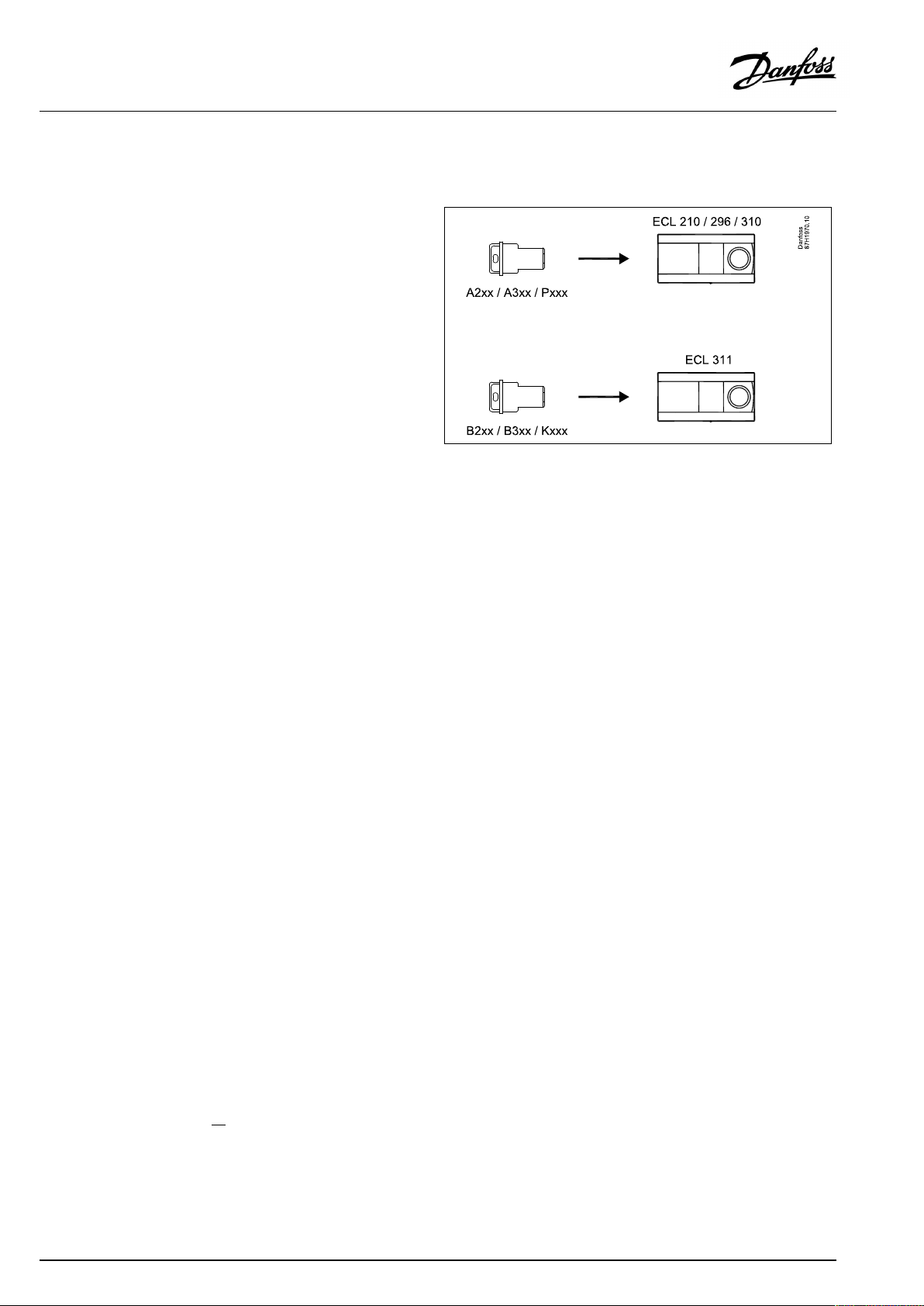
ThisOperatingGuideisassociatedwith:
•ECLApplicationKeyA230
(ordercodeno.087H3802)forECLComfort210/296/310
•ECLApplicationKeyB230
(ordercodeno.087H3902)forECLComfort311
TheECLApplicationKeysA230andB230contain5subtypes:
•A230.1:Temperaturecontrolinheatinginstallations.Optional
compensationfromwind.Electronicbypassfunction.
•A230.2:Temperaturecontrolincoolinginstallations.Optional
externalsignal(0-10V)forflowtemperaturesetpoint.
•A230.3:Temperaturecontrolinheatinginstallations.
Compensationforhighrelativehumidity.Optional
compensationfromwind.
•A230.4:Temperaturecontrolinheatinginstallations.Pressure
measurementbyS8or,alternatively,useS8asexternalsignal(0
-10V)fortemperaturesetpoint.Electronicbypassfunction.
•A230.5:Temperaturecontrolinheatinginstallations.Flow
temperature-basedcontrolofcirculationpump.Alarminput.
PressuremeasurementbyS8or,alternatively,useS8asexternal
signal(0-10V)forflowtemperaturesetpoint.
TheA230/B230applicationkeyalsocontainsaFloor(Screed)
DryingProgramforthesubtypesA230.1,A230.3,A230.4and
A230.5.Seeseparatedocumentation.(InEnglishandGerman
languageonly).
Electronicbypassfunction(A230.1andA230.4)isusedtoensure
sufficientsupplytemperaturefromtheDistrictHeatingUtilityfor
heatingaself-actingDHWcircuit(DomesticHotWater).
Temperatures,measuredbyheat-meterviaM-Bus
ThesubtypesA230.1,A230.3andA230.5can,whenusedinECL296
/310/311,utilizetheflowandreturntemperaturesensorvaluesof
theheat-meter.Thevalueforflowtemperatureisusedinsteadof
S4(supplytemperature);thevalueforreturntemperatureisused
insteadofS5(returntemperature).
SeetheInstallationGuide(deliveredwiththeapplicationkey)for
applicationexamplesandelectricalconnections.
Theapplicationdiagramsshowmandatorytemperaturesensors
withanunderscore;exampleS3
.
2|©Danfoss|2022.01
AQ163786479450en-010801
Page 3

ECLComfort210/296/310/311,applicationkeysA230andB230
A230
Thedescribedfunctionsarerealizedin:
•ECLComfort210forbasicsolutions
•ECLComfort296forbasicsolutions,inclusiveM-bus,Modbus
andEthernet(Internet)communication
•ECLComfort310foradvancedsolutions,inclusiveM-bus,
ModbusandEthernet(Internet)communication.Theextension
moduleECA32canbeused,viaa0-10Voltoutput,to
controlamodulatedactuator,forexampleDanfosstypesAME.
Furthermore,theextensionmoduleECA32canbeusedfor
extendingthenumbersofinputsformonitoringviatheECL
Portal.EachinputcanbeconfiguredasPt1000,0-10Voltor
digital.
TheApplicationKeyA230complieswithECLComfort210/310
controllersasoffirmwareversion1.11.
TheApplicationKeyA230compliesalsowithECLComfort296
controllersasoffirmwareversion1.58.
Thefirmware(controllersoftware)versionisvisibleatstart-upof
thecontrollerandin‘Commoncontrollersettings’in‘System’ .
UptotwoRemoteControlUnits,ECA30orECA31,canbe
connectedforremotemonitoringandsetting.Thebuilt-inroom
temperaturesensorcanbeutilized.
ECLPortal,Internetbasedconnection,allowsECL296,310and
310Btobemonitoredandcontrolledremotelyviastandard
Internetbrowsers(forexampleInternetExplorer,MicrosoftEdge,
GoogleChromeandSafari).
AQ163786479450en-010801
©Danfoss|2022.01|3
Page 4

ECLComfort210/296/310/311,applicationkeysA230andB230
TogetherwiththeECLComfort310,theadditionalInternalI/O
moduleECA32(ordercodeno.087H3202)canbeusedforextra
datacommunicationtoSCADA:
•Temperature,Pt1000(default)
•0-10voltsignals
•Digitalinput
Theset-upofinputtypecanbedonebymeansoftheDanfoss
Software"ECLTool".
Navigation:Danfoss.com>Serviceandsupport>Downloads>
Tools>Heating>ECLTool.
TheURLis:
https://www.danfoss.com/en/service-and-support/downloads/
TheInternalI/OmoduleECA32isplacedinthebasepartforECL
Comfort310.
ECLComfort210isavailableas:
•ECLComfort210,230volta.c.(087H3020)
•ECLComfort210B,230volta.c.(087H3030)
ECLComfort296isavailableas:
•ECLComfort296,230volta.c.(087H3000)
ECLComfort310isavailableas:
•ECLComfort310,230volta.c.(087H3040)
•ECLComfort310B,230volta.c.(087H3050)
•ECLComfort310,24volta.c.(087H3044)
TheB-typeshavenodisplayanddial.TheB-typesareoperatedby
meansoftheRemoteControlunitECA30/31:
•ECA30(087H3200)
•ECA31(087H3201)
BasepartsforECLComfort:
•forECLComfort210,230volt(087H3220)
•forECLComfort296,230volt(087H3240)
•forECLComfort310,230voltand24volt(087H3230)
AdditionaldocumentationforECLComfort210,296and310,
modulesandaccessoriesisavailableonhttp://danfoss.com/or
http://store.danfoss.com.
DocumentationforECLPortal:Seehttp://ecl.portal.danfoss.com.
4|©Danfoss|2022.01
AQ163786479450en-010801
Page 5

ECLComfort210/296/310/311,applicationkeysA230andB230
B230
Thedescribedfunctionsarerealizedin:
•ECLComfort311formultiplesolutions,inclusiveM-bus,
ModbusandEthernet(Internet)communication.Theextension
moduleECA32canbeused,viaa0-10Voltoutput,tocontrola
modulatedactuator,forexampleDanfosstypesAME.
Furthermore,theextensionmoduleECA32canbeusedfor
extendingthenumbersofinputsformonitoringviatheECL
Portal.EachinputcanbeconfiguredasPt1000,0-10Voltor
digital.
TheApplicationKeyB230complieswithECLComfort311
controllersasoffirmwareversion11.01.
Thefirmware(controllersoftware)versionisvisibleatstart-upof
thecontrollerandin‘Commoncontrollersettings’in‘System’ .
ECLPortal,Internetbasedconnection,allowsECL311tobe
monitoredandcontrolledremotelyviastandardInternetbrowsers
(forexampleInternetExplorer,GoogleChromeandSafari).
TogetherwiththeECLComfort311,theadditionalInternalI/O
moduleECA32(ordercodeno.087H3202)canbeusedforextra
datacommunicationtoSCADA:
•Temperature,Pt1000(default)
•0-10Voltsignals
•Digitalinput
Theset-upofinputtypecanbedonebymeansoftheDanfoss
Software"ECLTool".Navigation:Danfoss.com>Serviceand
support>Downloads>Tools>Heating>ECLTool.TheURLis:
https://www.danfoss.com/en/service-and-support/downloads/
TheInternalI/OmoduleECA32isplacedinthebasepartforECL
Comfort311.
ECLComfort311isavailableas:
•ECLComfort311,230Volta.c.(087H3041)
ECLComfort311cannotbeoperatedbymeansoftheRemote
ControlunitECA30/31.
AdditionaldocumentationforECLComfort210,296,310and
311,modulesandaccessoriesisavailableonhttp://danfoss.com/
orhttp://store.danfoss.com.DocumentationforECLPortal:See
http://ecl.portal.danfoss.com.
AQ163786479450en-010801
©Danfoss|2022.01|5
Page 6
ECLComfort210/296/310/311,applicationkeysA230andB230
SafetyNote
Toavoidinjuryofpersonsanddamagestothedevice,itisabsolutely
necessarytoreadandobservetheseinstructionscarefully.
Necessaryassembly,start-up,andmaintenanceworkmustbe
performedbyqualifiedandauthorizedpersonnelonly.
Locallegislationsmustberespected.Thiscomprisesalsocable
dimensionsandtypeofisolation(doubleisolatedat230V).
AfusefortheECLComfortinstallationismax.10Atypically.
TheambienttemperaturerangesforECLComfortinoperationare:
ECLComfort210/310/311:0-55°C
ECLComfort296:0-45°C.
Exceedingthetemperaturerangecanresultinmalfunctions.
Installationmustbeavoidedifthereisariskforcondensation(dew).
Thewarningsignisusedtoemphasizespecialconditionsthatshould
betakenintoconsideration.
Thissymbolindicatesthatthisparticularpieceofinformationshould
bereadwithspecialattention.
Applicationkeysmightbereleasedbeforealldisplaytextsare
translated.InthiscasethetextisinEnglish.
6|©Danfoss|2022.01
AQ163786479450en-010801
Page 7
ECLComfort210/296/310/311,applicationkeysA230andB230
Automaticupdateofcontrollersoftware(firmware):
Thesoftwareofthecontrollerisupdatedautomaticallywhenthekey
isinserted:
•ECL210/310,asofcontrollerversion1.11
•ECL296,asofcontrollerversion1.58
•ECL311,asofcontrollerversion11.01
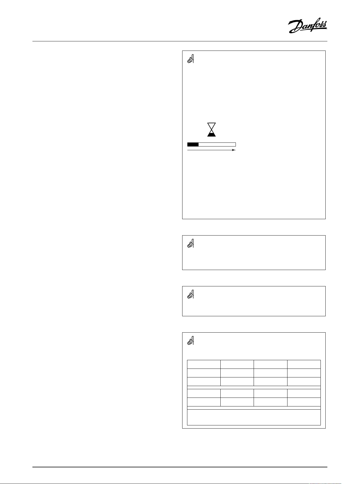
Thefollowinganimationwillbeshownwhenthesoftwareisbeing
updated:
Progressbar
Duringupdate:
•DonotremovetheKEY
•Donotdisconnectthepower
•Manualupdateofcontrollersoftware(firmware):
Ifthekeyisremovedbeforethehour-glassisshown,youhave
tostartafresh.
Ifthepowerisinterruptedwhenthehour-glassisshown,the
controllerwillnotwork.
Seethesection"Automatic/manualupdateoffirmware"
AsthisOperatingGuidecoversseveralsystemtypes,specialsystem
settingswillbemarkedwithasystemtype.Allsystemtypesareshown
inthechapter:'Identifyingyoursystemtype'.
°C(degreesCelsius)isameasuredtemperaturevaluewhereasK
(Kelvin)oftenisusedfortemperaturedifferences.
TheIDno.isuniquefortheselectedparameter.
ExampleFirstdigitSeconddigitLastthreedigits
1117411174
-
12174
IfanIDdescriptionismentionedmorethanonce,itmeansthatthere
arespecialsettingsforoneormoresystemtypes.Itwillbemarked
withthesystemtypeinquestion(e.g.12174-A266.9).
1
-
Circuit1Parameterno.
2
Circuit2Parameterno.
174
AQ163786479450en-010801
©Danfoss|2022.01|7
Page 8
ECLComfort210/296/310/311,applicationkeysA230andB230
ParametersindicatedwithanIDno.like"1x607"meanauniversal
parameter.
xstandsforcircuit/parametergroup.
DisposalNote
Thissymbolontheproductindicatesthatitmaynot
bedisposedofashouseholdwaste.
Itmustbehandedovertotheapplicabletake-back
schemefortherecyclingofelectricalandelectronic
equipment.
•Disposeoftheproductthroughchannelsprovided
forthispurpose.
•Complywithalllocalandcurrentlyapplicablelaws
andregulations.
8|©Danfoss|2022.01
AQ163786479450en-010801
Page 9
ECLComfort210/296/310/311,applicationkeysA230andB230
2.0Installation
2.1Beforeyoustart
ThesubtypesinA230/B230areveryflexible.Thesearethebasic
principles:
Heating(applicationA230.1):
Typically,theflowtemperatureisadjustedaccordingtoyour
requirements.TheflowtemperaturesensorS3isthemost
importantsensor.ThedesiredflowtemperatureatS3iscalculated
intheECLcontroller,basedontheoutdoortemperature(S1)and
thedesiredroomtemperature.
Thelowertheoutdoortemperature,thehigherthedesiredflow
temperature.
Bymeansofaweekschedule,theheatingcircuitcanbein
‘Comfort’or‘Saving’mode.Theweekschedulecanhaveupto3
‘Comfort’periods/day.Avalueforthedesiredroomtemperature
canbesetineachofthemodes.
InSavingmodetheheatingcanbereducedorswitchedofftotally.
ThemotorizedcontrolvalveM1isopenedgraduallywhenthe
flowtemperatureislowerthanthedesiredflowtemperatureand
viceversa.
ThereturntemperatureS5tothedistrictheatingsupplyshouldnot
betoohigh.Ifso,thedesiredflowtemperaturecanbeadjusted
(typicallytoalowervalue),thusresultinginagradualclosingofthe
motorizedcontrolvalve.
Inboiler-basedheatingsupplythereturntemperatureshouldnot
betoolow(sameadjustmentprocedureasabove).
Furthermore,thereturntemperaturelimitationcanbedependent
oftheoutdoortemperature.Typically,thelowertheoutdoor
temperature,thehighertheacceptedreturntemperature.
Ifthemeasuredroomtemperature(directlyconnectedtemperature
sensorESM-10(S2)orRemotecontrolunitECA30/31)doesnot
equalthedesiredroomtemperature,thedesiredflowtemperature
canbeadjusted.
Thecirculationpump,P1,isONatheatdemandoratfrost
protection.
TheheatingcanbeswitchedOFFwhentheoutdoortemperatureis
higherthanaselectablevalue.
Aconnectedfloworenergymeterbasedonpulses(S7)canlimit
thefloworenergytoasetmaximumvalue.Furthermore,the
limitationcanbeinrelationtotheoutdoortemperature.Typically,
thelowertheoutdoortemperature,thehighertheacceptedflow/
power.WhenthissubtypeisusedinanECLComfort296/310/311
theflow/energysignalcanalternativelycomeasanM-bussignal.
Thefrostprotectionmodemaintainsaselectableflowtemperature,
forexample10°C.
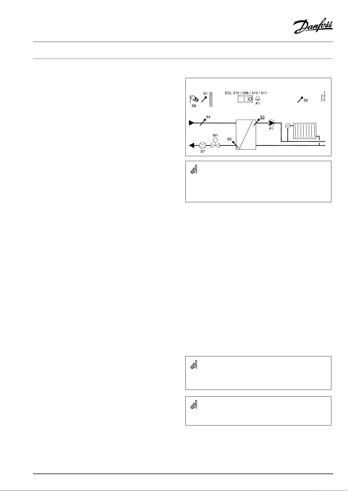
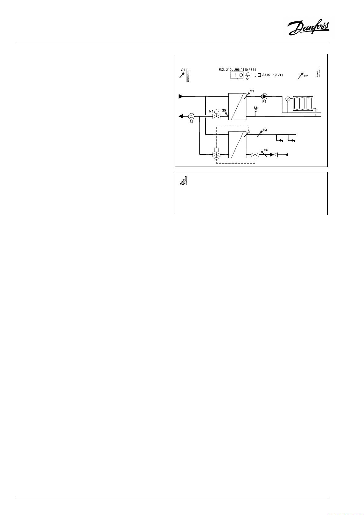
TypicalA230.1application:
Theshowndiagramisafundamentalandsimplifiedexampleanddoes
notcontainallcomponentsthatarenecessaryinasystem.
AllnamedcomponentsareconnectedtotheECLComfortcontroller.
Listofcomponents:
ECL210/296/
310/311
S1
S2
S3
S4
ElectroniccontrollerECLComfort210,296/310
/311
Outdoortemperaturesensor
(Optional)Roomtemperaturesensor/ECA30
(Mandatory)Flowtemperaturesensor
(Optional)Supplyflowtemperaturesensor
(read-outonly)
S5
S7
S8
P1
P2
M1
(Optional)Returntemperaturesensor
(Optional)Flow/energymeter(pulsesignal)
(Optional)Windspeedsignal(0-10V)
Circulationpump
(notillustrated)RelayoutputforSchedule2
Motorizedcontrolvalve,3-pointcontrolled
Alternative1:Controlvalve,thermo-actuator
controlled(DanfosstypeABV)
Alternative2(ECL310/311withECA32):Motorized
controlvalve,0-10Voltcontrolled
A1
TheA230.1applicationcanutilizeaconnectedflow/energymeter
tolimittheflow/power.
Alarm
Tocompensatefortheinfluenceofwind,awindspeedsensorcan
beconnected.Basedonthewindspeedsensorsignal(0-10V),the
controllercanbesettoincreasethedesiredflowtemperaturein
relationtoincreasedwindspeed.
Unusedinputs(fromS7andup)can,bymeansofanoverride
switchorrelaycontact,beusedforoverridingthescheduletoa
fixed'Comfort','Saving','Frostprotection'or'Constanttemperature'
mode.
Analarmcanbeactivatediftheactualflowtemperaturediffers
fromthedesiredflowtemperature.
AQ163786479450en-010801
ECA30/31doesnotworkwithECL311.
©Danfoss|2022.01|9
Page 10
ECLComfort210/296/310/311,applicationkeysA230andB230
Cooling(applicationA230.2):
Typically,theflowtemperatureisadjustedaccordingtoyour
requirements.TheflowtemperaturesensorS3isthemost
importantsensor.ThedesiredflowtemperatureatS3issetinthe
ECLcontroller.Furthermore,theoutdoortemperature(S1)can
influencethedesiredflowtemperature.Thehighertheoutdoor
temperature,thelowerthedesiredflowtemperature.
Bymeansoftheweekschedule,thecoolingcircuitcanbein
‘Comfort’or‘Saving’mode(twovaluesforthedesiredflow
temperature).
Theweekschedulealsocontrolstwovalues(‘Comfort’and
‘Saving’)forthedesiredroomtemperature.Ifthemeasuredroom
temperaturedoesnotequalthedesiredroomtemperature,the
desiredflowtemperaturecanbeadjusted.
ThemotorizedcontrolvalveM1isopenedgraduallywhenthe
flowtemperatureishigherthanthedesiredflowtemperatureand
viceversa.
ThereturntemperatureS5tothecoolingsupplyshouldnotbetoo
low.Ifso,thedesiredflowtemperaturecanbeadjusted(typicallyto
ahighervalue),thusresultinginagradualclosingofthemotorized
controlvalve.
Thecirculationpump,P1,isONatcoolingdemand.
Anexternalsignalforthedesiredflowtemperaturecanbeapplied
asa0–10voltsignaltotheterminalsforS8.
Aconnectedfloworenergymeterbasedonpulses(S7)canlimit
thefloworenergytoasetmaximumvalue.
WhentheA230.2isusedinanECLComfort296/310/311theflow
/energysignalcanalternativelycomeasanM-bussignal.
Thestandbymodemaintainsaselectableflowtemperature,for
example30°C.
Unusedinputs(fromS7andup)can,bymeansofanoverride
switchorrelaycontact,beusedforoverridingthescheduletoa
fixed'Comfort'or'Saving'mode.
ThetemperaturesS4andS6areusedformonitoringpurposesonly.
Theschedulein"Commoncontrollersettings"controlstherelays
2and3.Thiscanbeutilizedforshiftingbetweentwocirculation
pumps.
Seetheinstallationguide,appl.A230.2,ex.dandrelatedelectrical
connections.
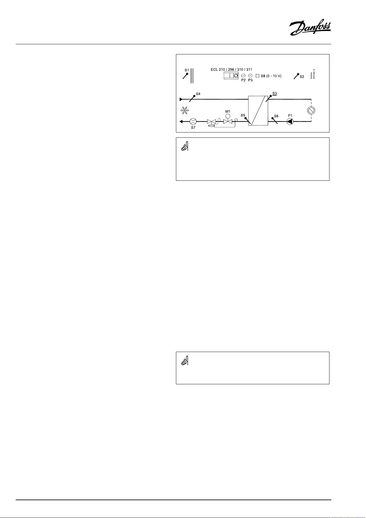
TypicalA230.2application:
Theshowndiagramisafundamentalandsimplifiedexampleanddoes
notcontainallcomponentsthatarenecessaryinasystem.
AllnamedcomponentsareconnectedtotheECLComfortcontroller.
Listofcomponents:
ECL210/296
ElectroniccontrollerECLComfort210/296/310/311
/310/311
S1
S2
S3
S4
(Optional)Outdoortemperaturesensor
(Optional)Roomtemperaturesensor/ECA30
(Mandatory)Flowtemperaturesensor,cooling
(Optional)Supplyflowtemperaturesensor(read-out
only)
S5
S6
S7
(Optional)Returntemperaturesensor
(Optional)Returntemperaturesensor(read-outonly)
(Optional)Flow/energymeter(pulsesignal),not
illustrated
(S8)
(Optional)(Externalvoltage(0–10V)forexternal
settingofdesiredflowtemperature)
P1
P2/P3
M1
Circulationpump
Schedule2
Motorizedcontrolvalve,3-pointcontrolled
Alternative1:Controlvalve,thermo-actuator
controlled(DanfosstypeABV)
Alternative2(ECL310/311withECA32):Motorized
controlvalve,0-10Voltcontrolled
10|©Danfoss|2022.01
TheA230.2applicationcanutilizeaconnectedflow/energymeter
tolimittheflow/power.
AQ163786479450en-010801
Page 11
ECLComfort210/296/310/311,applicationkeysA230andB230
Heating(applicationA230.3):
ThissubtypeworkslikeA230.1,buttheflow-orenergylimitation,
basedonpulsesignalisnotimplemented.Ifflow-orenergy
limitationisneeded,theM-Busbasedsignalcanbeused(ECL
Comfort296,310or311).
Inaddition,A230.3canminimizetheriskofdew(condensation).
TheRH(RelativeHumidity)signalcanarrangeaminimumdesired
roomtemperatureforprotectionagainstdew(condensation).
Dewcanoccurwhenairwithhightemperatureandhumidity
comestocolderwalls,forexampleinchurches,castlesandother
thick-wallbuildings.
Theequation-
T.dew=(0.96xT.room)+(0.25xRH)-22.4
isusedforcalculationofthedewtemperature(T.dew).
T.roomisthemeasuredroomtemperature.RHistheRelative
Humidity,basedonmeasuredroomtemperatureandhumidity.
RoomtemperatureandRHcomeseitherfrom
•theRemoteControlUnitECA31
or
•aroomtemperaturesensorandanappliedRHsignal,0-10
Volt,toS7.
TherelationshipbetweenappliedvoltageandrelatedRHvalue
canbeset.
AnOffsetvalueforthecalculateddewtemperature(T.dew)canbe
addedforcompensationbetweenwallandroomtemperatures.
Favoritedisplay1canshowthefollowing:
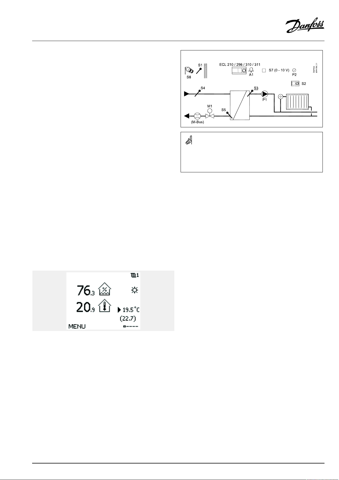
TypicalA230.3application:
Theshowndiagramisafundamentalandsimplifiedexampleanddoes
notcontainallcomponentsthatarenecessaryinasystem.
AllnamedcomponentsareconnectedtotheECLComfortcontroller.
Listofcomponents:
ECL210/296
ElectroniccontrollerECLComfort210/296/310/311
/310/311
S1
S2
S3
S4
Outdoortemperaturesensor
(Optional)Roomtemperaturesensor/ECA31
(Mandatory)Flowtemperaturesensor
(Optional)Supplyflowtemperaturesensor(read-out
only)
S5
S7
S8
P1
P2
M1
(Optional)Returntemperaturesensor
(Optional)RHsignal(0-10V)
(Optional)Windspeedsignal(0-10V)
Circulationpump
(notillustrated)RelayoutputforSchedule2
Motorizedcontrolvalve,3-pointcontrolled
Alternative1:Controlvalve,thermo-actuator
controlled(DanfosstypeABV)
Alternative2(ECL310/311withECA32):Motorized
controlvalve,0-10Voltcontrolled
A1
Alarm
RHvalue:76.3%
Roomtemperature:20.9°C
Desiredroomtemperature:19.5°C
Minimumdesiredroomtemperature,inclusive6Koffset:22.7°C
AQ163786479450en-010801
©Danfoss|2022.01|11
Page 12
ECLComfort210/296/310/311,applicationkeysA230andB230
Heating(A230.4)
ThissubtypeworksassubtypeA230.1,butthewindinfluence
functionalityisnotimplemented.
Inaddition,A230.4canmonitorDHW(DomesticHotWater)
temperaturesS4andS6.
Anappliedvoltagesignal(0-10Volt)toS8canbeusedfor:
•pressuremeasuring.ThevoltageisconvertedintheECL
controllertoapressure,measuredinbar
or
•settingthedesiredflowtemperature.Thevoltageisconverted
intheECLcontrollertoatemperaturevalue.
TypicalA230.4application:
Theshowndiagramisafundamentalandsimplifiedexampleanddoes
notcontainallcomponentsthatarenecessaryinasystem.
AllnamedcomponentsareconnectedtotheECLComfortcontroller.
Listofcomponents:
ECL210/296
ElectroniccontrollerECLComfort210/296/310/311
/310/311
S1
S2
S3
S4
Outdoortemperaturesensor
(Optional)Roomtemperaturesensor/ECA30
(Mandatory)Flowtemperaturesensor
(Optional)DHWflowtemperaturesensor(read-out
only)
S5
S6
(Optional)Returntemperaturesensor
(Optional)DHWcirculationreturntemperature
sensor(read-outonly)
S7
S8
(Optional)Flow/energymeter(pulsesignal)
(Optional)0-10Voltsignalfrompressuresensor
Alternative:0-10Voltsignalforexternalsettingof
desiredflowtemperature
P1
M1
Circulationpump,heating
Motorizedcontrolvalve,3-pointcontrolled
Alternative1:Controlvalve,thermo-actuator
controlled(DanfosstypeABV)
Alternative2(ECL310/311withECA32):Motorized
controlvalve,0-10Voltcontrolled
A1
Alarm
12|©Danfoss|2022.01
AQ163786479450en-010801
Page 13
ECLComfort210/296/310/311,applicationkeysA230andB230
Heating(A230.5)
ThissubtypeworksassubtypeA230.1,butthewindinfluence
functionalityisnotimplemented.Inaddition,A230.5controlsthe
circulationpumpP1atheatdemandtobeswitchedOFFifthe
flowtemperatureS3islowerthanasetvalue(f.ex.28°C).The
circulationpumpwillbeswitchedONwhentheflowtemperature
S3getsaboveanothersetvalue(f.ex.32°C).Thisfunctionprevents
heatedwatertogobackinthedistrictheatingnetworkifthe
supplytemperatureistoolow.
Furthermore,thecontrolvalvepositioncanbedisplayed,basedon
avariableresistanceappliedtoinputS6.Seewiringdiagraminthe
InstallationGuide.InputS7actsasanalarminput.
Anappliedvoltagesignal(0-10Volt)toS8canbeusedfor:
•pressuremeasuring.ThevoltageisconvertedintheECL
controllertoapressure,measuredinbar
or
•settingthedesiredflowtemperature.Thevoltageisconverted
intheECLcontrollertoatemperaturevalue.
Specialinfo:
IfreturntemperaturesensorS5isnotconnected,thereturn
temperaturevaluecancomefromanM-Busconnectedheat-meter.
Thevaluewillnot*)beshowninthedisplayoftheECL,butdespite
ofthat,thevaluecanbeusedforreturntemperaturelimitation.
Furthermore,thereturntemperaturevaluefromtheM-Bus
connectedheat-meterisshowninECLPortal/LeanHeat®Monitor.
*)updatesoftheapplicationsubtypetoV02andupwillshowthe
returntemperaturevaluefromtheheat-meter.
SeetheInstallationGuide(deliveredwiththeapplicationkey)for
applicationexampleandelectricalconnections.
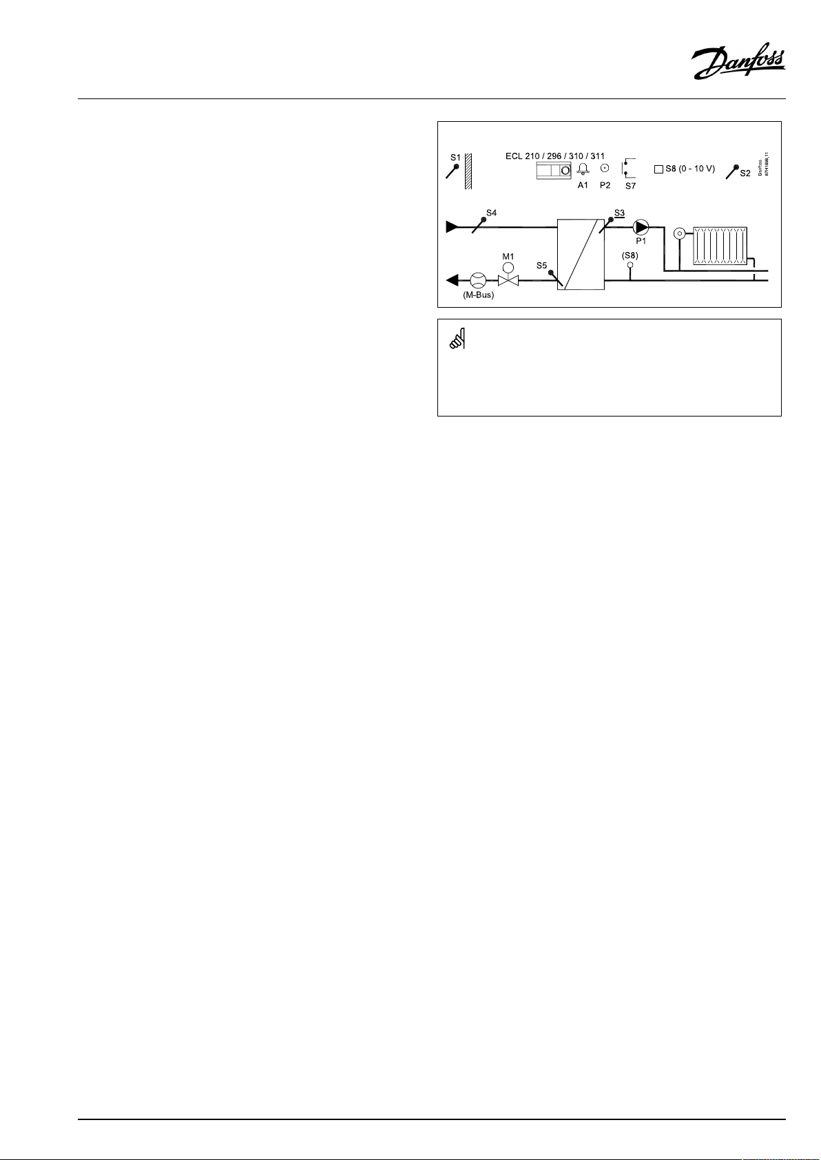
TypicalA230.5application:
Theshowndiagramisafundamentalandsimplifiedexampleanddoes
notcontainallcomponentsthatarenecessaryinasystem.
AllnamedcomponentsareconnectedtotheECLComfortcontroller.
Listofcomponents:
ECL210/296
/310/311
S1
S2
S3
S4
ElectroniccontrollerECLComfort210,296,310or
311
Outdoortemperaturesensor
(Optional)Roomtemperaturesensor/ECA30
(Mandatory)Flowtemperaturesensor
(Optional)Supplyflowtemperaturesensor.For
monitoringpurpose.S4-valuecan,ifsupply
temperaturesensorisnotconnected,comefroman
M-Busconnectedheat-meter.
S5
(Optional)Returntemperaturesensor.
S5-valuecan,ifreturntemperaturesensoris
notconnected,comefromanM-Busconnected
heat-meter.
S6
S7
S8
(Optional)M1'sposition
(Optional)Alarminput
(Optional)0-10Voltsignalfrompressuresensor
Alternative:0-10Voltsignalforexternalsettingof
desiredflowtemperature.
P1
P2
M1
Circulationpump
RelayoutputforSchedule2
Motorizedcontrolvalve,3-pointcontrolled.
Alternative1:Controlvalve,thermo-actuator
controlled(DanfosstypeABV).
Alternative2(ECL310/311withECA32):Motorized
controlvalve,0-10Voltcontrolled.
A1
M-Bus
Alarm
Heat-meterconnectedviaM-Bus
AQ163786479450en-010801
©Danfoss|2022.01|13
Page 14

ECLComfort210/296/310/311,applicationkeysA230andB230
A230,ingeneral:
UptotwoRemoteControlUnits,ECA30/31,canbeconnectedto
oneECLcontrollertocontroltheECLcontrollerremotely.
SeveralECLcontrollers,internallyconnectedviaECL485bus,work
inMaster/Slaveconnection.InaMaster/Slavesystemmaximum
2ECA30/31canbepresent.
A230/B230,ingeneral:
Exerciseofcirculationpumpsandcontrolvalveinperiodswithout
heatingorcoolingdemandcanbearranged.
AdditionalECLComfortcontrollerscanbeconnectedviatheECL
485bustoutilizecommonoutdoortemperaturesignal,timeand
datesignals.
SeveralECLcontrollers,internallyconnectedviaECL485bus,work
inMaster/Slaveconnection.
Anunusedinputcan,bymeansofanoverrideswitch,beusedto
overridethescheduletoafixedmode:
PossibilitiesforA230.1,A230.3,A230.4andA230.5:
'Comfort','Saving','Frostprotection'or'Constanttemperature'
mode
PossibilitiesforA230.2:
'Comfort'or'Saving'mode
Heat-meters:
Upto5heat-meterscanbeconnectedtotheM-busterminals(ECL
296/310/311).
DatacanbetransferredtotheSCADAsystemviaModbusandTCP/
IPtotheECLPortal.
Temperatures,measuredbyheat-meter
ThesubtypesA230.1,A230.3andA230.5can,whenusedinECL296
/310/311,utilizetheheat-meter'sflowandreturntemperature
sensorvalues.Thevalueforflowtemperatureisusedinsteadof
S4(supplytemperature);thevalueforreturntemperatureisused
insteadofS5(returntemperature).
DirectlyconnectedtemperaturesensorsS4andS5havepriority
overthetemperaturevaluesfromtheheat-meter.
ThetemperaturevaluesforS4andS5,whencomingfromthe
heat-meter,willtypicallyappear10sec.afterpower-up.
Modbuscommunication(ECLComfort296/310/311)toaSCADA
systemcanbeestablished.
TheM-busdata(ECLComfort296/310/311)canfurthermorebe
transferredtotheModbuscommunication.
Alarm
A230.1,A230.3,A230.4andA230.5:
AlarmA1(=relay4)canbeactivatedif:
•theactualflowtemperaturediffersfromthedesiredflow
temperature.
•atemperaturesensororitsconnectiondisconnects/short
circuits.(See:Commoncontrollersettings>System>Raw
inputoverview).
A230.2:
Alarmrelay4isnotused,butatemperaturesensororits
connectionscanbemonitored.
(See:Commoncontrollersettings>System>Rawinputoverview).
A230.4andA230.5:
AlarmA1(=relay4)canbeactivatedif:
•theactualpressureisnotinsideanacceptablepressurerange
A230.5:
AlarmA1(=relay4)canbeactivatedif:
•thealarminputS7isactivated
14|©Danfoss|2022.01
AQ163786479450en-010801
Page 15

ECLComfort210/296/310/311,applicationkeysA230andB230
A230/B230,ingeneral(continued):
Offsetadjustment
Ameasuredtemperaturecanbeoffsetadjusted,ifneeded.
(Navigation:MENU>Commoncontroller>System>Sensoroffset)
Inputconfiguration
Inputs(asfromS7andup)whicharenotpartoftheapplicationcan
beconfiguredtobePt1000,0-10Volt,frequency(pulsecounter)
orDigitalinput.ThisfeaturemakesitpossibleinECL296/310/
311tocommunicateextrasignals,suchastemperatures,pressures,
ON/OFFconditions,viaModbusandECLPortal.
TheconfigurationisdonebymeansoftheECLTool(freesoftware
fordownload)ordirectlyinadedicatedmenuintheECLPortalor
theconnectionforModbus(BMS/SCADA).
Applicationupload
Theapplicationuploadprocedureisthefollowingafterhaving
powereduptheECLComfortcontroller:
1.Inserttheapplicationkey
2.Selectlanguage
3.Selectsubtype(theInstallationGuideshowssubtypes)
4.SetTimeandDate
TheECLComfortcontrollerinstallstheapplication,initializesand
restarts.Outputrelaysareactivated/de-activated(click-sounds
fromthiscanbeheard).Thisalsomeansthat,forexample,
circulationpumpscanbeswitchedONandOFFshortly.
Commissioning
WhentheapplicationhasbeenuploadedtheECLComfort
controllerstartsinManualmode.Thiscanbeusedtoverifycorrect
connectionsoftemperature,pressureandflowsensors.Also
verifyingthecontrolledcomponents(valveactuators,pumpsetc.)
forcorrectfunctionalitycanbedone.
Theapplicationkeyisdeliveredwithfactorysettings.
Dependingonsystemtype,itmightbenecessarytochangesome
factorysettingsindividuallyinordertooptimizethefunctionality.
Theapplicationkeymustbeinsertedinordertochangesettings.
Power-down/power-up
WhenthepowersupplytotheECLComfortcontrolleris
disconnected(power-down),theoutputrelaysgotode-activated
position.
Thismeansthat,forexample,circulationpumpscanbeswitched
ON.
SeetheelectricalconnectiondiagramsintheInstallationGuide.
Allrelaycontactsareshowninde-activatedsituation.Somerelay
contactsareclosed,somerelaycontactsareopen.
WhenthepowersupplytotheECLComfortcontrolleris
re-established(power-up),theoutputrelaysareactivated/
de-activated(click-soundsfromthiscanbeheard).Thisalsomeans
that,forexample,circulationpumpscanbeswitchedONandOFF
shortly.
Important:
•Setthecorrectrunningtime"Mrun"oftheMotorizedControl
ValveM1.(Circuit1>MENU>Settings>Controlparameters
>Mrun).
AQ163786479450en-010801
©Danfoss|2022.01|15
Page 16

ECLComfort210/296/310/311,applicationkeysA230andB230
Thecontrollerispre-programmedwithfactorysettingsthatareshown
inthe‘ParameterIDoverview’appendix.
16|©Danfoss|2022.01
AQ163786479450en-010801
Page 17
ECLComfort210/296/310/311,applicationkeysA230andB230
2.2Identifyingthesystemtype
Sketchyourapplication
TheECLComfortcontrollerseriesisdesignedforawiderange
ofheating,domestichot-water(DHW)andcoolingsystemswith
differentconfigurationsandcapacities.Ifyoursystemdiffers
fromthediagramsshownhere,youmaywanttomakeasketch
ofthesystemabouttobeinstalled.Thismakesiteasiertouse
theOperatingGuide,whichwillguideyoustep-by-stepfrom
installationtofinaladjustmentsbeforetheend-usertakesover.
TheECLComfortcontrollerisauniversalcontrollerthatcanbe
usedforvarioussystems.Basedontheshownstandardsystems,
itispossibletoconfigureadditionalsystems.Inthischapteryou
findthemostfrequentlyusedsystems.Ifyoursystemisnotquite
asshownbelow,findthediagramwhichhasthebestresemblance
withyoursystemandmakeyourowncombinations.
SeetheInstallationGuide(deliveredwiththeapplicationkey)for
applicationtypes/sub-types.
Thecirculationpump(s)inheatingcircuit(s)canbeplacedintheflow
aswellasthereturn.Placethepumpaccordingtothemanufacturer’s
specification.
AQ163786479450en-010801
©Danfoss|2022.01|17
Page 18
ECLComfort210/296/310/311,applicationkeysA230andB230
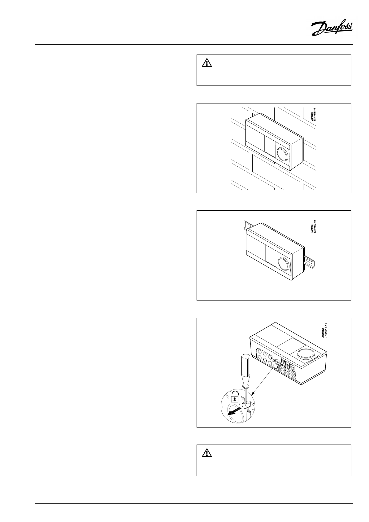
2.3Mounting
2.3.1MountingtheECLComfortcontroller
SeetheInstallationGuidewhichisdeliveredtogetherwiththe
ECLComfortcontroller.
Foreasyaccess,youshouldmounttheECLComfortcontrollernear
thesystem.
ECLComfort210/296/310/311canbemounted
•onawall
•onaDINrail(35mm)
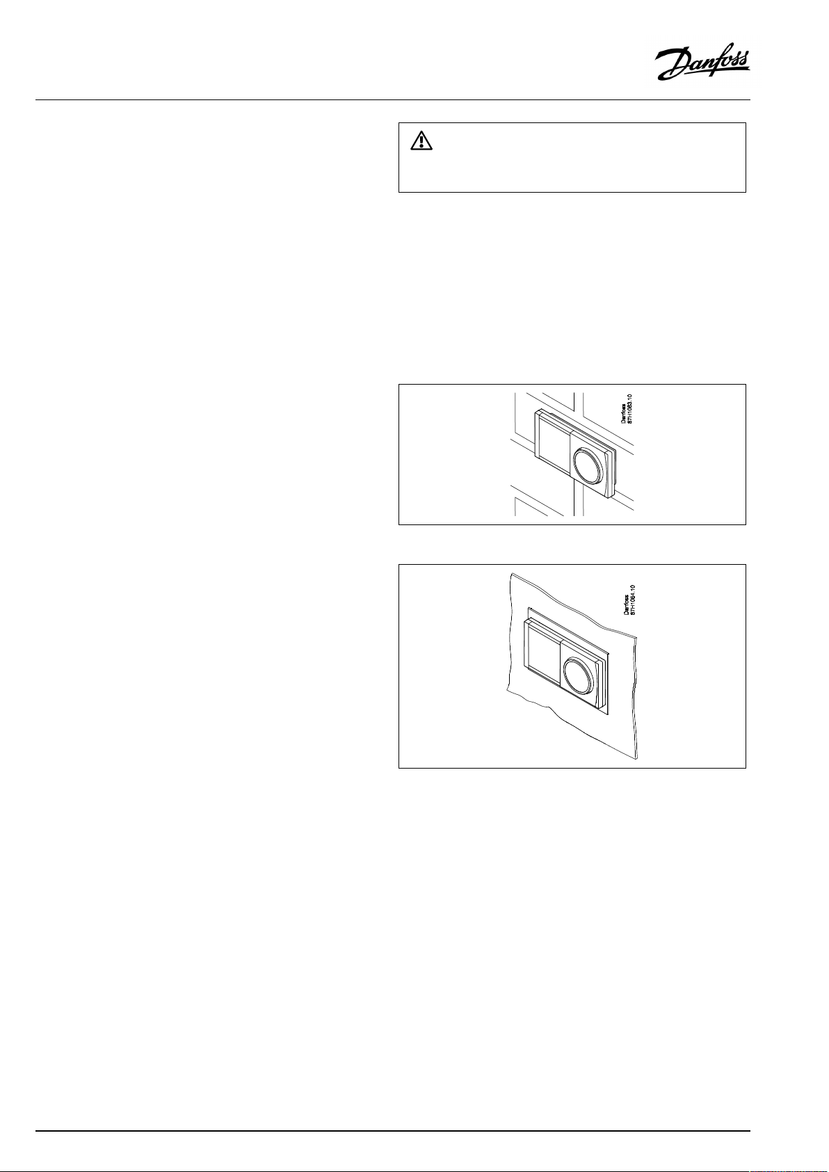
ECLComfort296canbemounted
•inapanelcut-out
ECLComfort210canbemountedinanECLComfort310basepart
(forfutureupgrade).
Screws,PGcableglandsandrawlplugsarenotsupplied.
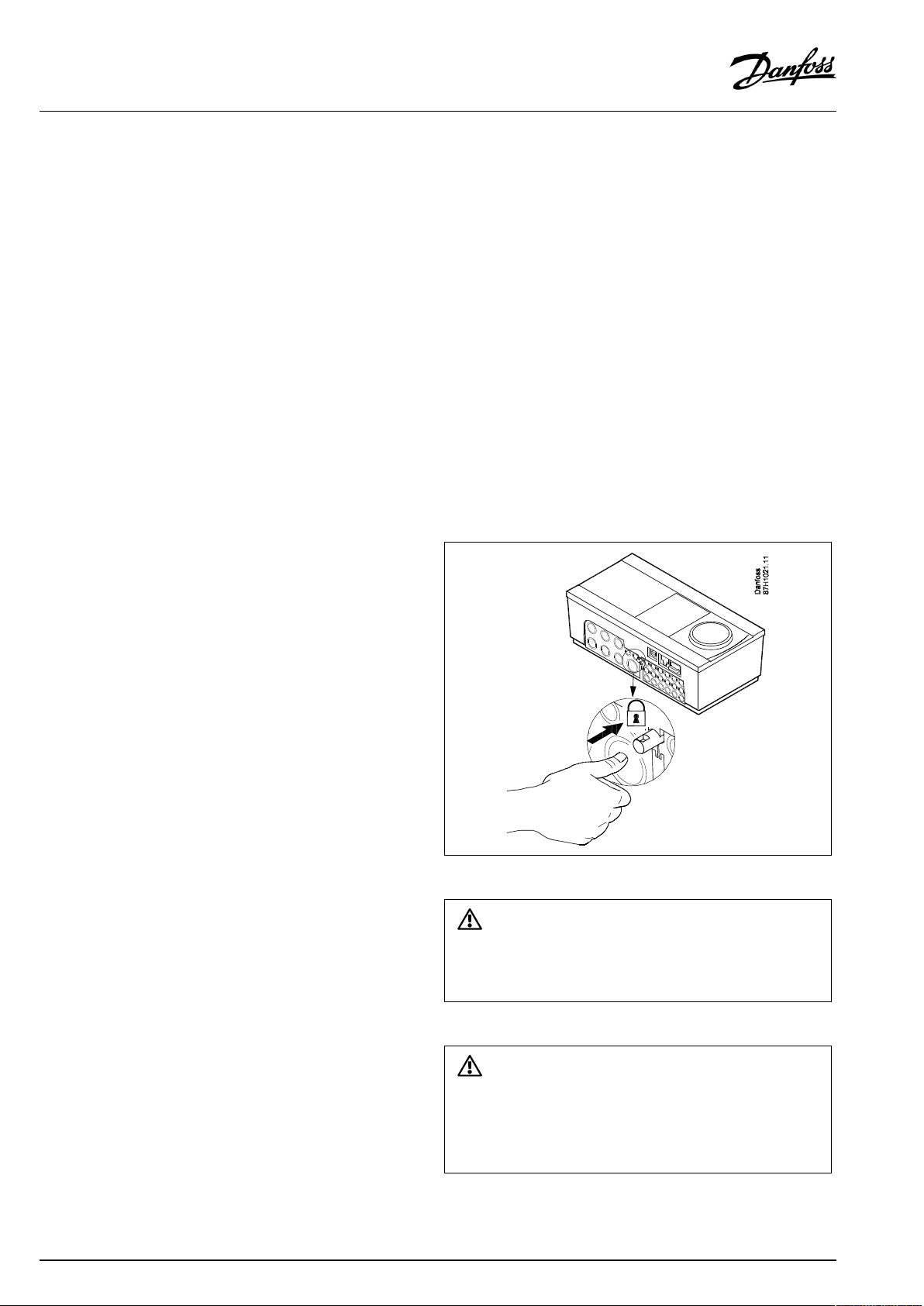
LockingtheECLComfort210/310/311controller
InordertofastentheECLComfortcontrollertoitsbasepart,secure
thecontrollerwiththelockingpin.
18|©Danfoss|2022.01
Topreventinjuriestopersonsorthecontroller,thecontrollerhasto
besecurelylockedintothebase.Forthispurpose,pressthelocking
pinintothebaseuntilaclickisheardandthecontrollernolonger
canberemovedfromthebase.
Ifthecontrollerisnotsecurelylockedintothebasepart,thereisarisk
thatthecontrollerduringoperationcanunlockfromthebaseandthe
basewithterminals(andalsothe230Va.c.connections)areexposed.
Topreventinjuriestopersons,alwaysmakesurethatthecontroller
issecurelylockedintoitsbase.Ifthisisnotthecase,thecontroller
shouldnotbeoperated!
AQ163786479450en-010801
Page 19
ECLComfort210/296/310/311,applicationkeysA230andB230
Theeasywaytolockthecontrollertoitsbaseorunlockitistousea
screwdriveraslever.
Mountingonawall
Mountthebasepartonawallwithasmoothsurface.Establishthe
electricalconnectionsandpositionthecontrollerinthebasepart.
Securethecontrollerwiththelockingpin.
MountingonaDINrail(35mm)
MountthebasepartonaDINrail.Establishtheelectrical
connectionsandpositionthecontrollerinthebasepart.Secure
thecontrollerwiththelockingpin.
DismountingtheECLComfortcontroller
Inordertoremovethecontrollerfromthebasepart,pulloutthe
lockingpinbymeansofascrewdriver.Thecontrollercannowbe
removedfromthebasepart.
Theeasywaytolockthecontrollertoitsbaseorunlockitistousea
screwdriveraslever.
AQ163786479450en-010801
©Danfoss|2022.01|19
Page 20
ECLComfort210/296/310/311,applicationkeysA230andB230
BeforeremovingtheECLComfortcontrollerfromthebasepart,ensure
thatthesupplyvoltageisdisconnected.
2.3.2MountingtheRemoteControlUnitsECA30/31
Selectoneofthefollowingmethods:
•Mountingonawall,ECA30/31
•Mountinginapanel,ECA30
Screwsandrawlplugsarenotsupplied.
Mountingonawall
MountthebasepartoftheECA30/31onawallwithasmooth
surface.Establishtheelectricalconnections.PlacetheECA30/
31inthebasepart.
Mountinginapanel
MounttheECA30inapanelusingtheECA30framekit(ordercode
no.087H3236).Establishtheelectricalconnections.Securethe
framewiththeclamp.PlacetheECA30inthebasepart.TheECA
30canbeconnectedtoanexternalroomtemperaturesensor.
TheECA31mustnotbemountedinapanelifthehumidity
functionistobeused.
20|©Danfoss|2022.01
AQ163786479450en-010801
Page 21
ECLComfort210/296/310/311,applicationkeysA230andB230
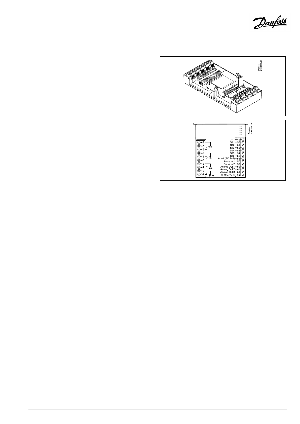
2.3.3MountingtheinternalI/OmoduleECA32
MountingoftheinternalI/OmoduleECA32
TheECA32module(ordercodeno.087H3202)mustbeinserted
intotheECLComfort310/310B/311basepartforadditionalinput
andoutputsignalsinrelevantapplications.
TheconnectionbetweentheECLComfort310/310B/311andECA
32isa10-pole(2x5)connector.Theconnectionisautomatically
establishedwhentheECLComfort310/310B/311isplacedon
thebasepart.
AQ163786479450en-010801
©Danfoss|2022.01|21
Page 22
ECLComfort210/296/310/311,applicationkeysA230andB230
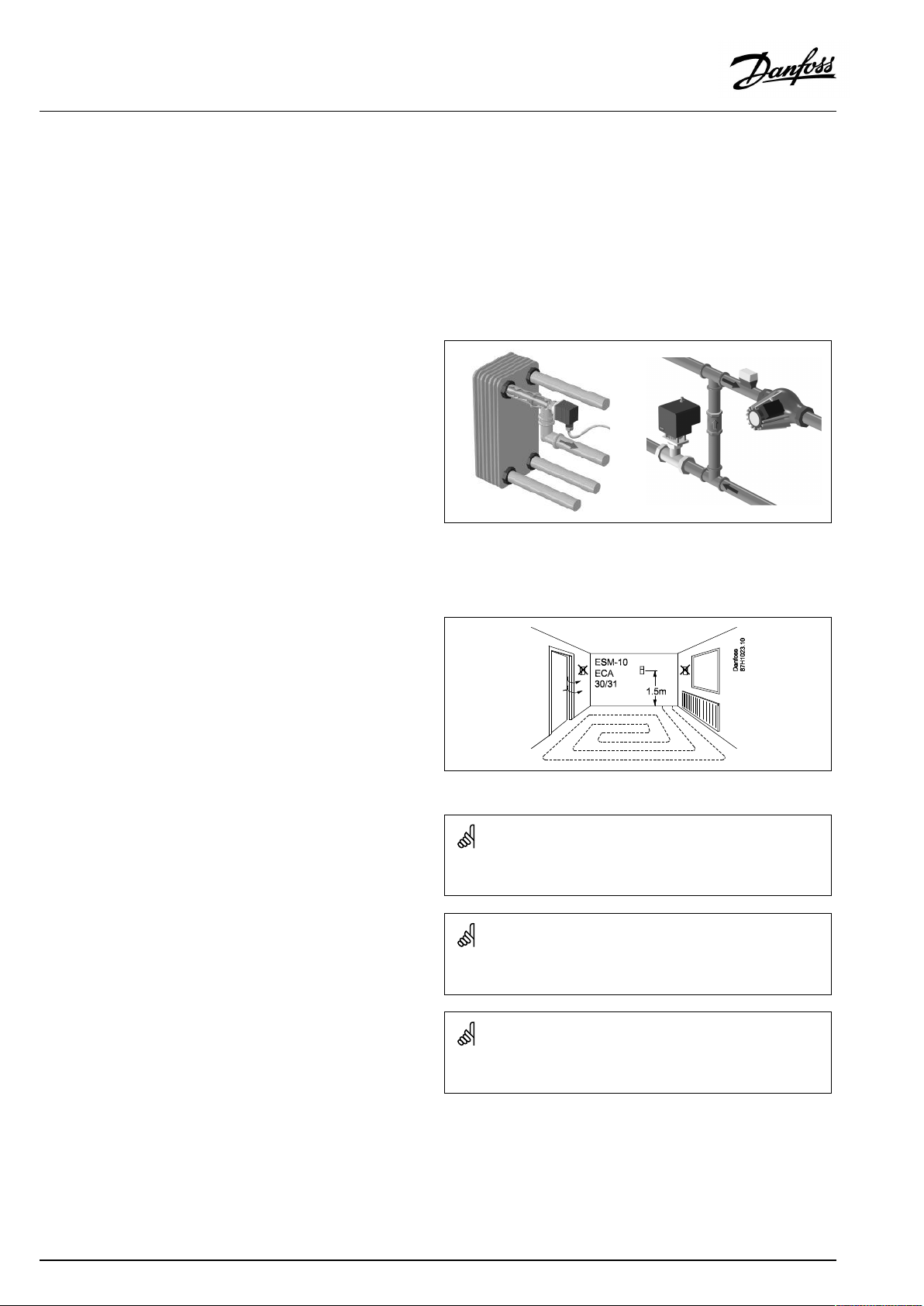
2.4Placingthetemperaturesensors
2.4.1Placingthetemperaturesensors
Itisimportantthatthesensorsaremountedinthecorrectposition
inyoursystem.
Thetemperaturesensormentionedbelowaresensorsusedfor
theECLComfort210/296/310/311serieswhichnotallwillbe
neededforyourapplication!
Outdoortemperaturesensor(ESMT)
Theoutdoorsensorshouldbemountedonthatsideofthebuilding
whereitislesslikelytobeexposedtodirectsunshine.Itshouldnot
beplacedclosetodoors,windowsorairoutlets.
Flowtemperaturesensor(ESMU,ESM-11orESMC)
Placethesensormax.15cmfromthemixingpoint.Insystems
withheatexchanger,DanfossrecommendsthattheESMU-typeto
beinsertedintotheexchangerflowoutlet.
Makesurethatthesurfaceofthepipeiscleanandevenwhere
thesensorismounted.
Returntemperaturesensor(ESMU,ESM-11orESMC)
Thereturntemperaturesensorshouldalwaysbeplacedsothatit
measuresarepresentativereturntemperature.
Roomtemperaturesensor
(ESM-10,ECA30/31RemoteControlUnit)
Placetheroomsensorintheroomwherethetemperatureistobe
controlled.Donotplaceitonoutsidewallsorclosetoradiators,
windowsordoors.
Boilertemperaturesensor(ESMU,ESM-11orESMC)
Placethesensoraccordingtotheboilermanufacturer’s
specification.
Airducttemperaturesensor(ESMB-12orESMUtypes)
Placethesensorsothatitmeasuresarepresentativetemperature.
DHWtemperaturesensor(ESMUorESMB-12)
PlacetheDHWtemperaturesensoraccordingtothemanufacturer’s
specification.
Slabtemperaturesensor(ESMB-12)
Placethesensorinaprotectiontubeintheslab.
ESM-11:Donotmovethesensorafterithasbeenfastenedinorderto
avoiddamagetothesensorelement.
ESM-11,ESMCandESMB-12:Useheatconductingpasteforquick
measurementofthetemperature.
ESMUandESMB-12:Usingasensorpockettoprotectthesensorwill,
however,resultinaslowertemperaturemeasurement.
22|©Danfoss|2022.01
AQ163786479450en-010801
Page 23
ECLComfort210/296/310/311,applicationkeysA230andB230
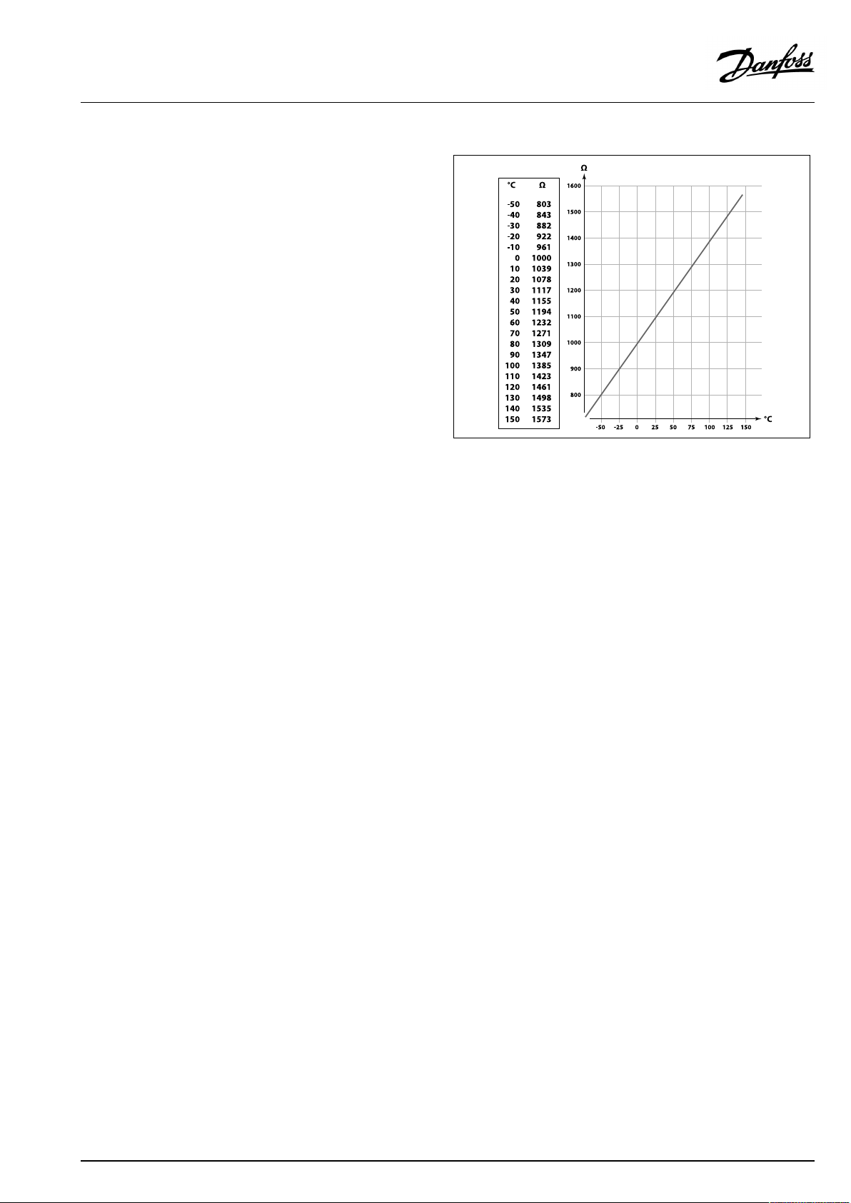
Pt1000temperaturesensor(IEC751B,1000Ω/0°C)
Relationshipbetweentemperatureandohmicvalue:
AQ163786479450en-010801
©Danfoss|2022.01|23
Page 24
ECLComfort210/296/310/311,applicationkeysA230andB230
2.5Electricalconnections
2.5.1Electricalconnections230Va.c.
Warning
ElectricconductorsonPCB(PrintedCircuitBoard)forsupplyvoltage,
relaycontactsandtriacoutputsdonothavemutualsafetydistanceof
minimum6mm.Theoutputsarenotallowedtobeusedasgalvanic
separated(voltfree)outputs.
Ifagalvanicseparatedoutputisneeded,anauxiliaryrelayis
recommended.
24Voltcontrolledunits,forexampleactuators,aretobecontrolledby
meansofECLComfort310,24Voltversion.
SafetyNote
Necessaryassembly,start-up,andmaintenanceworkmustbe
performedbyqualifiedandauthorizedpersonnelonly.
Locallegislationsmustberespected.Thiscomprisesalsocablesize
andisolation(reinforcedtype).
AfusefortheECLComfortinstallationismax.10Atypically.
TheambienttemperaturerangefortheECLComfortinoperationis
0-55°C.Exceedingthistemperaturerangecanresultinmalfunctions.
Installationmustbeavoidedifthereisariskforcondensation(dew).
24|©Danfoss|2022.01
AQ163786479450en-010801
Page 25
ECLComfort210/296/310/311,applicationkeysA230andB230
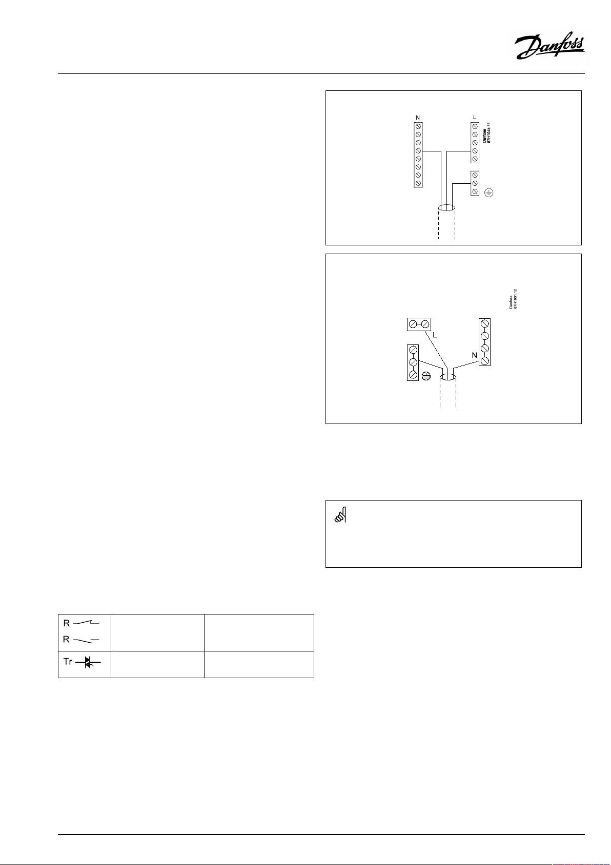
Thecommongroundterminalisusedforconnectionofrelevant
components(pumps,motorizedcontrolvalves).
ECL210/310/311
ECL296
SeealsotheInstallationGuide(deliveredwiththeapplicationkey)
forapplicationspecificconnections.
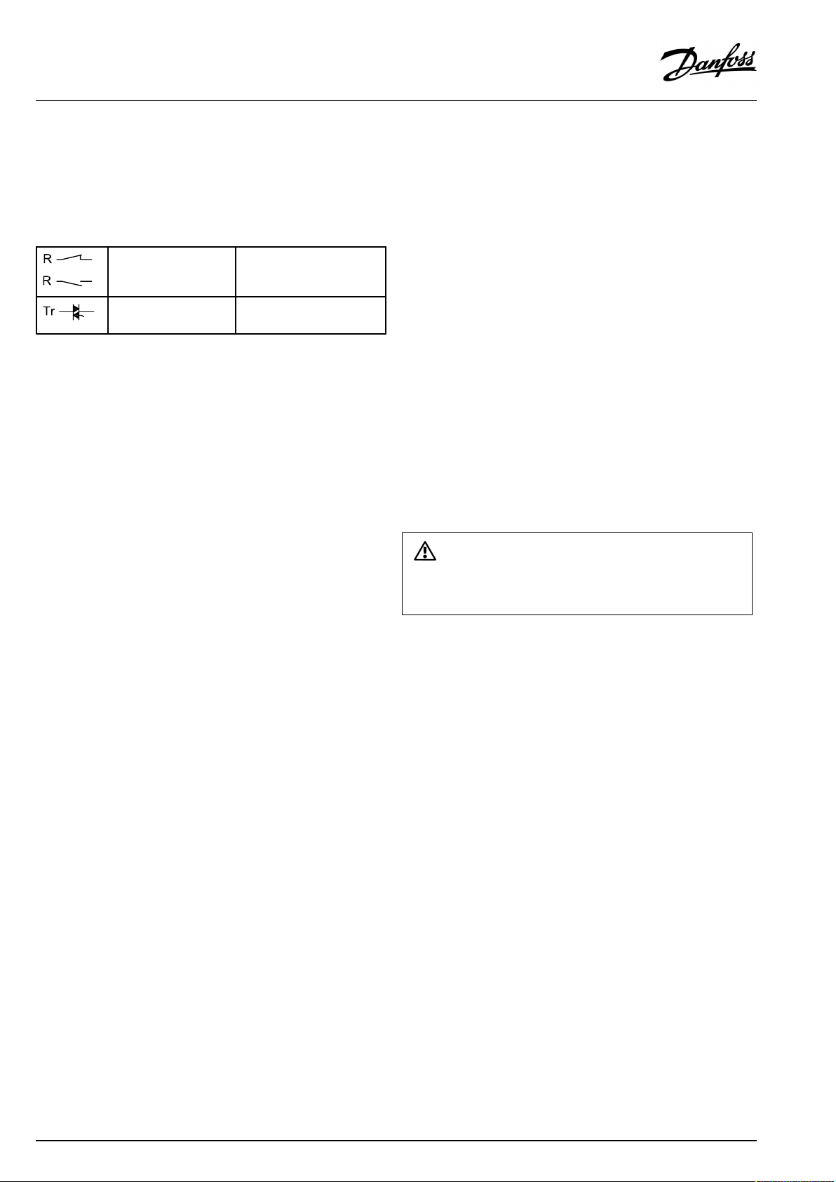
Maximumloadratings:
Relayterminals
4(2)A/230Va.c.
(4Aforohmicload,2Afor
inductiveload)
Triac(=electronic
0,2A/230Va.c.
relay)terminals
A230.2(cooling):2-pumpcontrol
ApplicationA230.2,ex.disanexampleforscheduledshiftbetween
twocirculationpumps.
ControlofP1isbasedonthecoolingdemandanddetermines
viaK1theON/OFFcontrolofthepumpsP2andP3.P2andP3
arerelatedtotheoutputoftheschedulein"Commoncontroller
settings".
TheelectricdiagramforA230.2,P2andP3showsanexamplefor
connection.
Wirecrosssection:0.5-1.5mm²
Incorrectconnectioncandamagetheelectronicoutputs.
Max.2x1.5mm²wirescanbeinsertedintoeachscrewterminal.
AQ163786479450en-010801
©Danfoss|2022.01|25
Page 26
ECLComfort210/296/310/311,applicationkeysA230andB230
2.5.2Electricalconnections24Va.c.
SeealsotheInstallationGuide(deliveredwiththeapplicationkey)
forapplicationspecificconnections.
Maximumloadratings:
Relayterminals
4(2)A/24Va.c.
(4Aforohmicload,2Afor
inductiveload)
Triac(=electronic
1A/24Va.c.
relay)terminals
A230.2(cooling):2-pumpcontrol
ApplicationA230.2,ex.disanexampleforscheduledshiftbetween
2circulationpumps.
ControlofP1isbasedonthecoolingdemandanddetermines
viaK1theON/OFFcontrolofthepumpsP2andP3.P2andP3
arerelatedtotheoutputoftheschedulein"Commoncontroller
settings".
TheelectricdiagramforA230.2,P2andP3showsanexamplefor
connection.
Donotconnect230Va.c.poweredcomponentstoa24Va.c.power
suppliedcontrollerdirectly.Useauxilliaryrelays(K)toseparate230
Va.c.from24Va.c.
26|©Danfoss|2022.01
AQ163786479450en-010801
Page 27
ECLComfort210/296/310/311,applicationkeysA230andB230
2.5.3Electricalconnections,safetythermostats,ingeneral
SeealsotheInstallationGuide(deliveredwiththeapplicationkey)
forapplicationspecificconnections.
Theconnectiondiagramsshowvarioussolutions/examples:
Safetythermostat,1–stepclosing:
Motorizedcontrolvalvewithoutsafetyfunction
Safetythermostat,1–stepclosing:
Motorizedcontrolvalvewithsafetyfunction
Safetythermostat,2–stepclosing:
Motorizedcontrolvalvewithsafetyfunction
WhenSTisactivatedbyahightemperature,thesafetycircuitinthe
motorizedcontrolvalveclosesthevalveimmediately.
WhenST1isactivatedbyahightemperature(theTRtemperature),the
motorizedcontrolvalveisclosedgradually.Atahighertemperature
(theSTtemperature),thesafetycircuitinthemotorizedcontrolvalve
closesthevalveimmediately.
AQ163786479450en-010801
©Danfoss|2022.01|27
Page 28
ECLComfort210/296/310/311,applicationkeysA230andB230
2.5.4Electricalconnections,Pt1000temperaturesensorsandsignals
SeealsotheInstallationGuide(deliveredwiththeapplicationkey)
forapplicationspecificconnections.
Sensor
S1
S2
Description
Outdoortemperaturesensor*
Roomtemperaturesensor**
Alternative:ECA30/31
S3
S4
Flowtemperaturesensor***
A230.1,A230.2,A230.3,
A230.5:Supplytemperature
sensor,formonitoring
A230.4:DHWtemperature
sensor,formonitoring
S5Returntemperaturesensor
S6A230.2:Returntemperature
sensor,formonitoring
A230.4:DHWcirculation
returntemperaturesensor,for
monitoring
A230.5:M1position
S7
A230.1,A230.2,A230.4:Flow/
energymeter(pulsesignal)
A230.3:RelativeHumidity
signal(0-10V)
A230.5:Alarm
S8
A230.2:Desiredcooling
temperature,0-10V
A230.4/A230.5:Pressure
transmitter,0-10V.
Alternatively,desiredheating
temperature,0-10V
Recommendedtype
ESMT
ESM-10
ESM-11/ESMB/
ESMC/ESMU
ESM-11/ESMB/
ESMC/ESMU
ESM-11/ESMB/
ESMC/ESMU
ESM-11/ESMB/
ESMC/ESMU
*
Iftheoutdoortemperaturesensorisnotconnectedorthe
cableisshort-circuited,thecontrollerassumesthatthe
outdoortemperatureis0(zero)°C.
**
Onlyforroomtemperaturesensorconnection.Theroom
temperaturesignalcanalsobeavailablefromaRemote
ControlUnit(ECA30/31).SeetheInstallationGuide
(deliveredwiththeapplicationkey)forspecificconnections.
***
Theflowtemperaturesensormustalwaysbeconnected
inordertohavethedesiredfunctionality.Ifthesensoris
notconnectedorthecableisshort-circuited,themotorized
controlvalvecloses(safetyfunction).
Wirecrosssectionforsensorconnections:Min.0.4mm².
Totalcablelength:Max.200m(allsensorsincl.internalECL485
communicationbus).
Cablelengthsofmorethan200mmaycausenoisesensibility(EMC).
28|©Danfoss|2022.01
AQ163786479450en-010801
Page 29

ECLComfort210/296/310/311,applicationkeysA230andB230
Connectionofflow/energymeterwithpulsesignal
SeetheInstallationGuide(deliveredwiththeapplicationkey).
Theoutputoftheflow/energymetercanbeequippedwithan
externalpull-upresistorifaninternalpull-upresistorisnotpresent.
Pulsebasedsignalforflow/power ,appliedtoinputS7
Formonitoring:
Frequencyrangeis0.01-200Hz
Forlimitation:
Minimumfrequencyisrecommendedtobe1Hzinordertohavea
stablecontrol.Furthermore,thepulsesmustappearregularly.
A230.1,A230.3
Connectionofwindspeedsensor
SeetheInstallationGuide(deliveredwiththeapplicationkey).
A230.4,A230.5
Connectionofpressuresensor
SeetheInstallationGuide(deliveredwiththeapplicationkey).
Set-upofrelationbetweenappliedvoltage(0-10V)from
pressuresensorandexpressedpressure(inBar)inECL:Seesection
Frequentlyaskedquestions.
AQ163786479450en-010801
©Danfoss|2022.01|29
Page 30
ECLComfort210/296/310/311,applicationkeysA230andB230
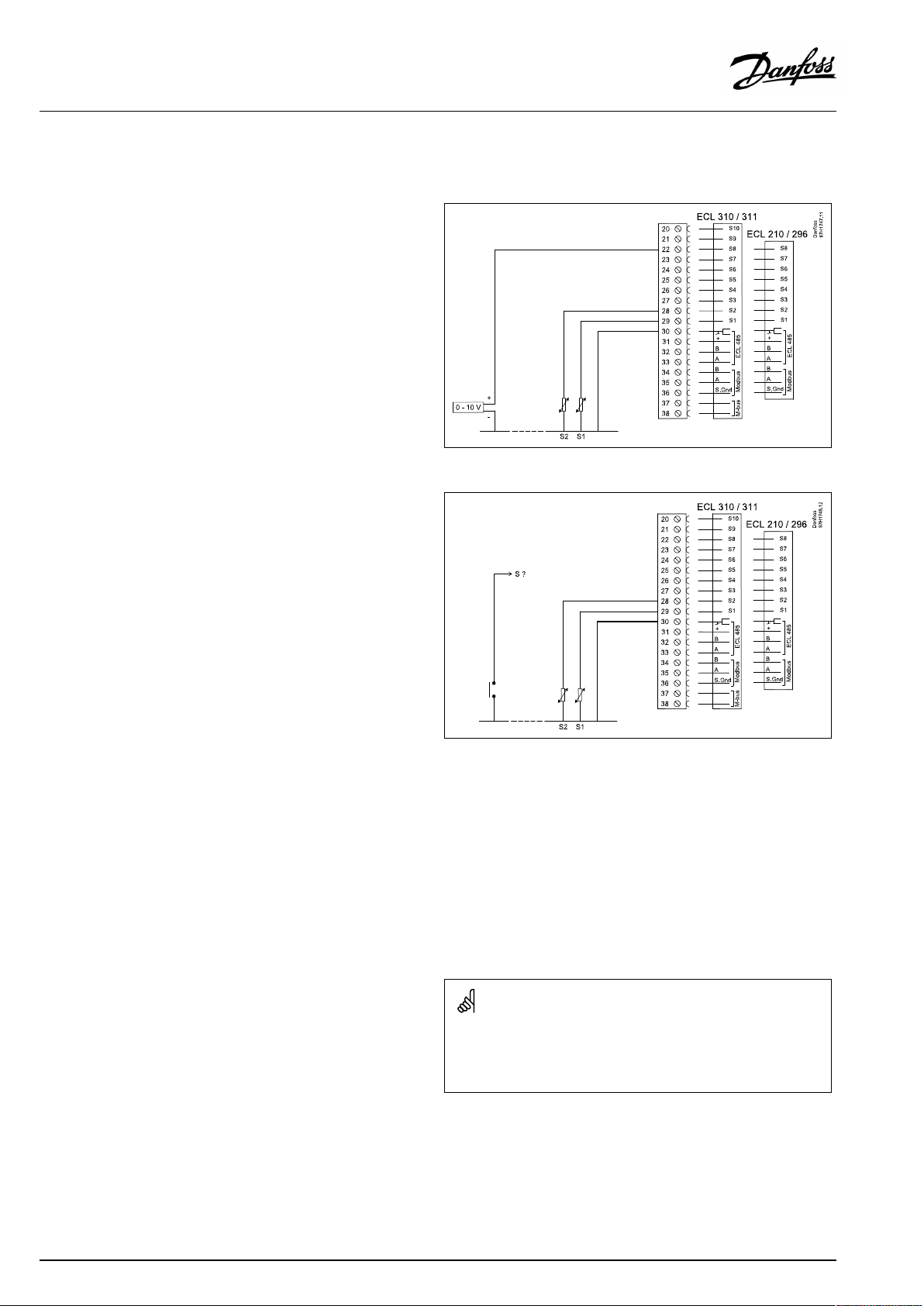
A230.2,A230.4,A230.5
Connectionofexternalvoltage(0–10V)forexternalsetting
ofdesiredflowtemperature
Connectionofswitchforexternaloverride
S?:
ECL210/296:S7-S8
ECL310:S7-S10
ECL310/311+ECA32:S7-S16
Usinganinputforoverriderequiresavoltfreecontact/switch.
IfS1...S6ischosenasoverrideinput,theoverrideswitchmusthave
gold-platedcontacts.
IfS7...S16ischosenasoverrideinput,theoverrideswitchcanbea
standardcontact.
Wirecrosssectionforsensorconnections:Min.0.4mm².
Totalcablelength:Max.200m(allsensorsincl.internalECL485
communicationbus)
Cablelengthsofmorethan200mmaycausenoisesensibility(EMC).
30|©Danfoss|2022.01
AQ163786479450en-010801
Page 31

ECLComfort210/296/310/311,applicationkeysA230andB230
2.5.5Electricalconnections,ECA30/31
Terminal
ECL
Terminal
ECA30/31
30
31
4
1
322
333
4
5
*
Afteranexternalroomtemperaturesensorhasbeenconnected,
Description
Twistedpair
Twistedpair
Ext.roomtemperature
sensor*
Type
(recomm.)
Cable2x
twistedpair
ESM-10
ECA30/31mustberepowered.
ThecommunicationtotheECA30/31mustbesetupintheECL
Comfortcontrollerin'ECAaddr.'
TheECA30/31mustbesetupaccordingly.
AfterapplicationsetuptheECA30/31isreadyafter2–5min.A
progressbarintheECA30/31isdisplayed.
Iftheactualapplicationcontainstwoheatingcircuits,itispossible
toconnectanECA30/31toeachcircuit.Theelectricalconnections
aredoneinparallel.
Max.2ECA30/31canbeconnectedtoanECLComfort310controller
ortoECLComfort210/296/310controllersinamaster-slavesystem.
ECAinformationmessage:
‘Applicationreq.newerECA’:
Thesoftware(firmware)ofyourECAdoesnotcomplywiththe
software(firmware)ofyourECLComfortcontroller.Pleasecontact
yourDanfosssalesoffice.
Someapplicationsdonotcontainfunctionsrelatedtoactualroom
temperature.TheconnectedECA30/31willonlyfunctionasremote
control.
SetupproceduresforECA30/31:Seesection‘Miscellaneous’ .
AQ163786479450en-010801
©Danfoss|2022.01|31
Page 32

ECLComfort210/296/310/311,applicationkeysA230andB230
Totalcablelength:Max.200m(allsensorsincl.internalECL485
communicationbus).
Cablelengthsofmorethan200mmaycausenoisesensibility(EMC).
32|©Danfoss|2022.01
AQ163786479450en-010801
Page 33

ECLComfort210/296/310/311,applicationkeysA230andB230
2.5.6Electricalconnections,master/slavesystems
Thecontrollercanbeusedasmasterorslaveinmaster/slave
systemsviatheinternalECL485communicationbus(2xtwisted
paircable).
TheECL485communicationbusisnotcompatiblewiththeECL
businECLComfort110,200,300and301!
Terminal
Description
Type
(recomm.)
30
Commonterminal
+12V*,ECL485communicationbus
31
*OnlyforECA30/31andmaster/
slavecommunication
32
B,ECL485communicationbus
33
A,ECL485communicationbus
Cable2x
twistedpair
ECL485buscable
MaximumrecommendedlengthoftheECL485busiscalculatedlike
this:
Subtract"TotallengthofallinputcablesofallECLcontrollersinthe
master-slavesystem"from200m.
Simpleexamplefortotallengthofallinputcables,3xECL:
1xECL
3xECL
3xECLReturntemp.sensor:
3xECLRoomtemp.sensor:
Total:
Outdoortemp.sensor:
Flowtemp.sensor:
15m
18m
18m
30m
81m
2.5.7Electricalconnections,communication
Electricalconnections,Modbus
ECLComfort210:Non-galvanicisolatedModbusconnections
ECLComfort296:GalvanicisolatedModbusconnections
ECLComfort310/311:GalvanicisolatedModbusconnections
MaximumrecommendedlengthoftheECL485bus:
200-81m=119m
AQ163786479450en-010801
©Danfoss|2022.01|33
Page 34

ECLComfort210/296/310/311,applicationkeysA230andB230
2.5.8Electricalconnections,communication
Electricalconnections,M-bus
ECLComfort210:Notimplemented
ECLComfort296:Onboard,non-galvanicisolated.Max.cable
length50m.
ECLComfort310/311:Onboard,non-galvanicisolated.Max.
cablelength50m.
34|©Danfoss|2022.01
AQ163786479450en-010801
Page 35

ECLComfort210/296/310/311,applicationkeysA230andB230
2.6InsertingtheECLApplicationKey
2.6.1InsertingtheECLApplicationKey
TheECLApplicationKeycontains
•theapplicationanditssubtypes,
•currentlyavailablelanguages,
•factorysettings:e.g.schedules,desiredtemperatures,
limitationvaluesetc.Itisalwayspossibletorecoverthefactory
settings,
•memoryforusersettings:specialuser/systemsettings.
Afterhavingpowered-upthecontroller,differentsituationsmight
beexisting:
1.Thecontrollerisnewfromthefactory,theECLApplicationKey
isnotinserted.
2.Thecontrolleralreadyrunsanapplication.TheECLApplication
Keyisinserted,buttheapplicationneedstobechanged.
3.Acopyofthecontrollerssettingsisneededforconfiguring
anothercontroller.
ECLComfort210/310/311
ECLComfort210/310/311
Usersettingsare,amongothers,desiredroomtemperature,desired
DHWtemperature,schedules,heatcurve,limitationvaluesetc.
Systemsettingsare,amongothers,communicationset-up,display
brightnessetc.
AQ163786479450en-010801
ECLComfort296
©Danfoss|2022.01|35
Page 36

ECLComfort210/296/310/311,applicationkeysA230andB230
Automaticupdateofcontrollersoftware(firmware):
Thesoftwareofthecontrollerisupdatedautomaticallywhenthekey
isinserted:
•ECL210/310,asofcontrollerversion1.11
•ECL296,asofcontrollerversion1.58
•ECL311,asofcontrollerversion11.01
Thefollowinganimationwillbeshownwhenthesoftwareisbeing
updated:
Progressbar
Duringupdate:
•DonotremovetheKEY
•Donotdisconnectthepower
•Manualupdateofcontrollersoftware(firmware):
Ifthekeyisremovedbeforethehour-glassisshown,youhave
tostartafresh.
Ifthepowerisinterruptedwhenthehour-glassisshown,the
controllerwillnotwork.
Seethesection"Automatic/manualupdateoffirmware"
The“Keyoverview”doesnotinform—throughECA30/31—about
thesubtypesoftheapplicationkey.
Keyinserted/notinserted,description:
ECLComfort210/310,controllerversionslowerthan1.36:
-
Takeouttheapplicationkey;for20minutes
settingscanbechanged.
-
Powerupthecontrollerwithoutthe
applicationkeyinserted;for20minutes
settingscanbechanged.
ECLComfort210/310/311,controllerversions1.36andup:
-
Takeouttheapplicationkey;for20minutes
settingscanbechanged.
-
Powerupthecontrollerwithoutthe
applicationkeyinserted;settingscannotbe
changed.
ECLComfort296,controllerversions1.58andup:
-
Takeouttheapplicationkey;for20minutes
settingscanbechanged.
-
Powerupthecontrollerwithoutthe
applicationkeyinserted;settingscannotbe
changed.
36|©Danfoss|2022.01
AQ163786479450en-010801
Page 37

ECLComfort210/296/310/311,applicationkeysA230andB230
ApplicationKey:Situation1
Thecontrollerisnewfromthefactory,theECLApplicationKey
isnotinserted.
AnanimationfortheECLApplicationKeyinsertionisdisplayed.
InserttheApplicationKey.
ApplicationKeynameandVersionisindicated(example:A266
Ver.1.03).
IftheECLApplicationKeyisnotsuitableforthecontroller,a"cross"
isdisplayedovertheECLApplicationKey-symbol.
Action:Purpose:
Selectlanguage
Confirm
Selectapplication(subtype)
Somekeyshaveonlyoneapplication.
Confirmwith‘Yes’
Set'Time&Date'
Turnandpushthedialtoselectand
change'Hours' ,'Minutes','Date' ,
'Month'and'Year' .
Choose''Next'
Confirmwith‘Yes’
Goto‘Aut.daylight’
Choosewhether‘ Aut.daylight´*
shouldbeactiveornot
*‘Aut.daylight’istheautomaticchangeoverbetweensummer
andwintertime.
DependingonthecontentsoftheECLApplicationKey,procedure
AorBistakingplace:
A
TheECLApplicationkeycontainsfactorysettings:
Thecontrollerreads/transfersdatafromtheECLApplicationKey
toECLcontroller.
Examples:
YESorNO
Theapplicationisinstalled,andthecontrollerresetsandstartsup.
B
TheECLApplicationkeycontainschangedsystemsettings:
Pushthedialrepeatedly.
’NO’:
’YES*:
Ifthekeycontainsusersettings:
Pushthedialrepeatedly.
‘NO:
‘YES*:
*If‘YES’cannotbechosen,theECLApplicationKeydoesnot
containanyspecialsettings.
Choose‘Startcopying’andconfirmwith'Y es' .
AQ163786479450en-010801
OnlyfactorysettingsfromtheECLApplicationKeywill
becopiedtothecontroller.
Specialsystemsettings(differingfromthefactory
settings)willbecopiedtothecontroller.
OnlyfactorysettingsfromtheECLApplicationKeywill
becopiedtothecontroller.
Specialusersettings(differingfromthefactorysettings)
willbecopiedtothecontroller.
©Danfoss|2022.01|37
Page 38

ECLComfort210/296/310/311,applicationkeysA230andB230
(Example):
The"i"intheupperrightcornerindicatesthat-besidesthefactory
settings-thesubtypealsocontainsspecialuser/systemssettings.
ApplicationKey:Situation2
Thecontrolleralreadyrunsanapplication.TheECLApplication
Keyisinserted,buttheapplicationneedstobechanged.
TochangetoanotherapplicationontheECLApplicationKey,the
currentapplicationinthecontrollermustbeerased(deleted).
BeawarethattheApplicationKeymustbeinserted.
Action:Purpose:
Choose‘MENU’inanycircuit
Confirm
Choosethecircuitselectoratthetop
rightcornerinthedisplay
Confirm
Choose‘Commoncontrollersettings’
Confirm
Choose‘Keyfunctions’
Confirm
Choose‘Eraseapplication’
Confirmwith‘Yes’
Thecontrollerresetsandisreadytobeconfigured.
Followtheproceduredescribedinsituation1.
Examples:
38|©Danfoss|2022.01
AQ163786479450en-010801
Page 39

ECLComfort210/296/310/311,applicationkeysA230andB230
ApplicationKey:Situation3
Acopyofthecontrollerssettingsisneededforconfiguring
anothercontroller.
Thisfunctionisused
•forsaving(backup)ofspecialuserandsystemsettings
•whenanotherECLComfortcontrollerofthesametype(210,
296,310or311)mustbeconfiguredwiththesameapplication
butuser/systemsettingsdifferfromthefactorysettings.
HowtocopytoanotherECLComfortcontroller:
Action:Purpose:
Choose‘MENU’
Confirm
Choosethecircuitselectoratthetop
rightcornerinthedisplay
Confirm
Choose'Commoncontrollersettings'
Confirm
Goto‘Keyfunctions’
Confirm
Choose‘Copy’
Confirm
Choose‘To’ .
‘ECL’or‘KEY’willbeindicated.Choose
’ECL’orKEY’
Pushthedialrepeatedlytochoose
copydirection
Choose‘Systemsettings’or‘User
settings’
Pushthedialrepeatedlytochoose
‘Yes’or‘No’in‘Copy’ .Pushtoconfirm.
Choose‘Startcopying’
TheApplicationKeyorthecontroller
isupdatedwithspecialsystemoruser
settings.
Examples:
*
’ECL’or‘KEY’ .
**
‘NO’or‘YES’
*
‘ECL’:
‘KEY’:
**
‘NO’:
‘YES’:
AQ163786479450en-010801
DatawillbecopiedfromtheApplicationKeytothe
ECLController.
DatawillbecopiedfromtheECLControllertothe
ApplicationKey.
ThesettingsfromtheECLcontrollerwillnotbecopied
totheApplicationKeyortotheECLComfortcontroller.
Specialsettings(differingfromthefactorysettings)will
becopiedtotheApplicationKeyortotheECLComfort
controller.IfYEScannotbechosen,therearenospecial
settingstobecopied.
©Danfoss|2022.01|39
Page 40

ECLComfort210/296/310/311,applicationkeysA230andB230
Language
Atapplicationupload,alanguagemustbeselected.*
IfanotherlanguagethanEnglishisselected,theselectedlanguage
ANDEnglishwillbeuploadedintotheECLcontroller.
ThismakesserviceeasyforEnglishspeakingservicepeople,just
becausetheEnglishlanguagemenuscanbevisiblebychanging
theactualsetlanguageintoEnglish.
(Navigation:MENU>Commoncontroller>System>Language)
Iftheuploadedlanguageisnotsuitable,theapplicationmustbe
erased.UserandSystemsettingscanbesavedontheapplication
keybeforeerasing.
Afternewuploadwithpreferredlanguage,theexistingUserand
Systemsettingscanbeuploaded.
*)
(ECLComfort310,24Volt)Iflanguagecannotbeselected,the
powersupplyisnota.c.(alternatingcurrent).
2.6.2ECLApplicationKey,copyingdata
Generalprinciples
Whenthecontrollerisconnectedandoperating,youcancheck
andadjustallorsomeofthebasicsettings.Thenewsettingscan
bestoredontheKey.
Factorysettingscanalwaysberestored.
HowtoupdatetheECLApplicationKeyaftersettingshave
beenchanged?
AllnewsettingscanbestoredontheECLApplicationKey.
Howtostorefactorysettinginthecontrollerfromthe
ApplicationKey?
PleasereadtheparagraphconcerningApplicationKey,Situation
1:Thecontrollerisnewfromthefactory,theECLApplicationKey
isnotinserted.
HowtostorepersonalsettingsfromthecontrollertotheKey?
PleasereadtheparagraphconcerningApplicationKey,Situation3:
Acopyofthecontrollerssettingsisneededforconfiguringanother
controller
Asamainrule,theECLApplicationKeyshouldalwaysremainin
thecontroller.IftheKeyisremoved,itisnotpossibletochange
settings.
Makeanoteofnewsettingsinthe'Settingsoverview'table.
DonotremovetheECLApplicationKeywhilecopying.Thedataon
theECLApplicationKeycanbedamaged!
ItispossibletocopysettingsfromoneECLComfortcontrollerto
anothercontrollerprovidedthatthetwocontrollersarefromthesame
series(210,310or311).
Furthermore,whentheECLComfortcontrollerhasbeenuploaded
withanapplicationkey,minimumversion2.44,itispossibletoupload
personalsettingsfromapplicationkeys,minimumversion2.14.
40|©Danfoss|2022.01
AQ163786479450en-010801
Page 41

ECLComfort210/296/310/311,applicationkeysA230andB230
The“Keyoverview”doesnotinform—throughECA30/31—about
thesubtypesoftheapplicationkey.
Keyinserted/notinserted,description:
ECLComfort210/310,controllerversionslowerthan1.36:
ECLComfort210/310/311,controllerversions1.36andup:
ECLComfort296,controllerversions1.58andup:
-
Takeouttheapplicationkey;for20minutes
settingscanbechanged.
-
Powerupthecontrollerwithoutthe
applicationkeyinserted;for20minutes
settingscanbechanged.
-
Takeouttheapplicationkey;for20minutes
settingscanbechanged.
-
Powerupthecontrollerwithoutthe
applicationkeyinserted;settingscannotbe
changed.
-
Takeouttheapplicationkey;for20minutes
settingscanbechanged.
-
Powerupthecontrollerwithoutthe
applicationkeyinserted;settingscannotbe
changed.
AQ163786479450en-010801
©Danfoss|2022.01|41
Page 42

ECLComfort210/296/310/311,applicationkeysA230andB230
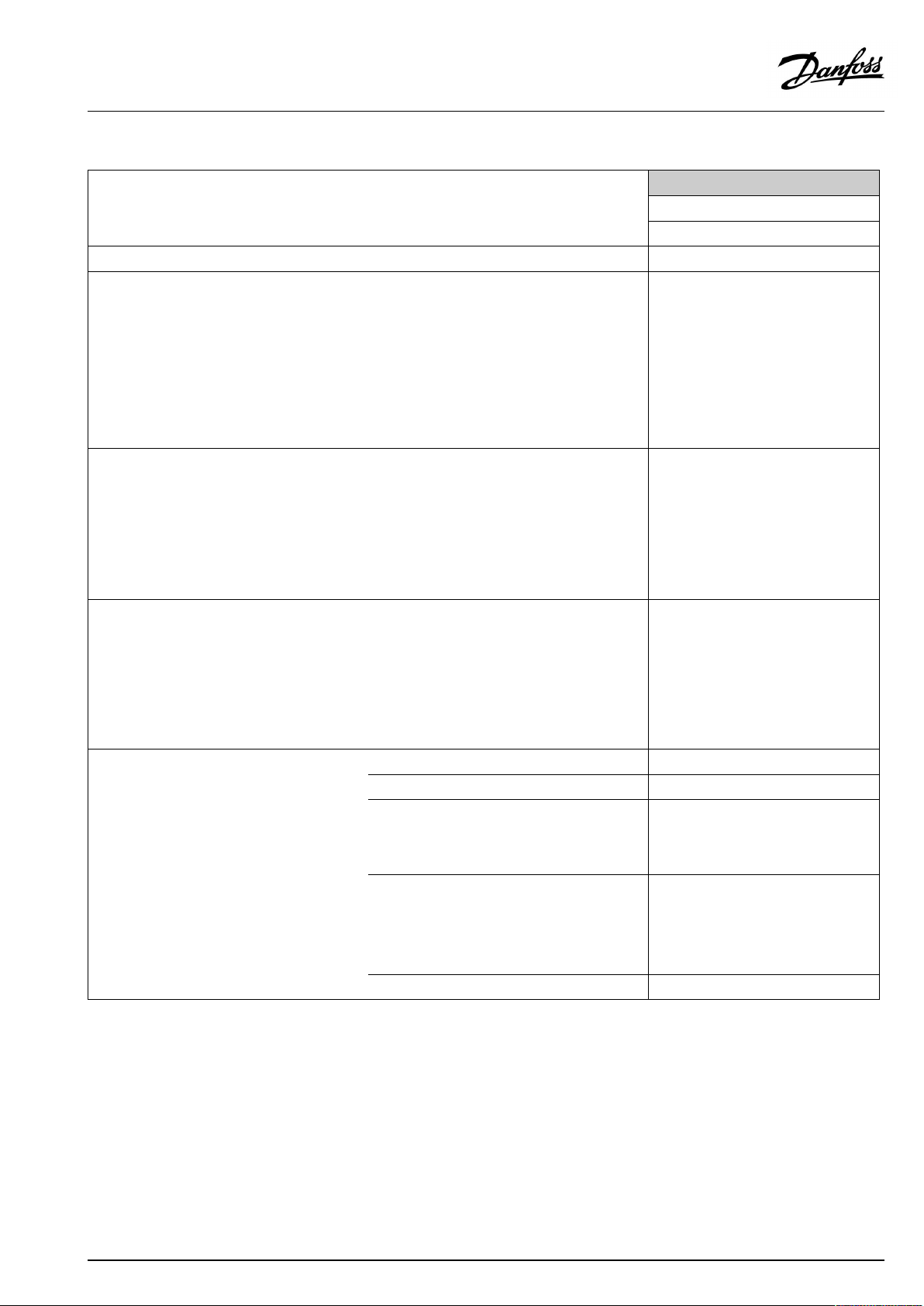
2.7Checklist
IstheECLComfortcontrollerreadyforuse?
Makesurethatthecorrectpowersupplyisconnectedtoterminals9and10(230Vor24V).
Makesurethecorrectphaseconditionsareconnected:
230V:Live=terminal9andNeutral=terminal10
24V:SP=terminal9andSN=terminal10
Checkthattherequiredcontrolledcomponents(actuator,pumpetc.)areconnectedtothecorrectterminals.
Checkthatallsensors/signalsareconnectedtothecorrectterminals(see'Electricalconnections').
Mountthecontrollerandswitchonthepower.
IstheECLApplicationKeyinserted(see'InsertingtheApplicationKey').
DoestheECLComfortcontrollercontainanexistingapplication(see'InsertingtheApplicationKey').
Isthecorrectlanguagechosen(see'Language'in'Commoncontrollersettings').
Isthetime&datesetcorrectly(see'Time&Date'in'Commoncontrollersettings').
Istherightapplicationchosen(see'Identifyingthesystemtype').
Checkthatallsettingsinthecontroller(see'Settingsoverview')aresetorthatthefactorysettingscomplywithyour
requirements.
Choosemanualoperation(see'Manualcontrol').Checkthatvalvesopenandclose,andthatrequiredcontrolled
components(pumpetc.)startandstopwhenoperatedmanually.
Checkthatthetemperatures/signalsshowninthedisplaymatchtheactualconnectedcomponents.
Havingcompletedthemanualoperationcheck,choosecontrollermode(scheduled,comfort,savingorfrostprotection).
42|©Danfoss|2022.01
AQ163786479450en-010801
Page 43

ECLComfort210/296/310/311,applicationkeysA230andB230
2.8Navigation,ECLApplicationKeyA230/B230
Navigation,A230/B230,applicationA230.1
Home
IDno.
MENU
ScheduleSelectable
Settings
Flowtemperature
11178
11177
11004
Roomlimit
Returnlimit
Flow/powerlimitActual
Windinfluence
11015
11182
11183
11031
11032
11033
11034
11035
11036
11037
11085
11029
11028
11119
11117
11118
11116
11112
11113
11109
11115
11114
11099
11057
11081
ApplicationA230.1
Function
Heatcurve
Temp.max.
Temp.min.
DesiredT
Adapt.time
Infl.-max.
Infl.-min.
HighToutX1
LowlimitY1
LowToutX2
HighlimitY2
Infl.-max.
Infl.-min.
Adapt.time
Priority
DHW,ret.Tlimit
Con.T,re.Tlim.
Limit
HighToutX1
LowlimitY1
LowToutX2
HighlimitY2
Adapt.time
Filterconstant
Inputtype
Units
Pulse
Windactual
Limit
Infl.-max.
Filterconstant
AQ163786479450en-010801
©Danfoss|2022.01|43
Page 44

ECLComfort210/296/310/311,applicationkeysA230andB230
Navigation,A230/B230,applicationA230.1,continued
Home
MENU
Settings
Optimization
Controlpar.
Application
Heatcut-out
IDno.
11011
11012
11013
11014
11026
11020
11021
11179
11174
11184
11185
11186
11187
11189
11024
11010
11017
11050
11500
11022
11023
11052
11077
11078
11040
11093
11141
11142
11393
11392
11179
11395
11397
11396
11398
11399
ApplicationA230.1
Function
Autosaving
Boost
Ramp
Optimizer
Pre-stop
Basedon
Totalstop
Summer,cut-out
Motorpr.
Xp
Tn
Mrun
Nz
Min.act.time
Actuator
ECAaddr.
Demandoffset
Pdemand
SenddesiredT
Pexercise
Mexercise
DHWpriority
PfrostT
PheatT
Ppost-run
Frostpr.T
Ext.input
Ext.mode
Sum.start,day
Sum.start,month
Summer,cut-out
Summer,filter
Winterstart,day
Winterstart,month
Winter,cut-out
Winter,filter
44|©Danfoss|2022.01
AQ163786479450en-010801
Page 45

ECLComfort210/296/310/311,applicationkeysA230andB230
Navigation,A230/B230,applicationA230.1,continued
Home
MENU
HolidaySelectable
Alarm
InfluenceoverviewDes.flowTReturnlim.
Temp.monitoring
AlarmoverviewSelectable
IDno.
11147
11148
11149
11150
ApplicationA230.1
Function
Upperdifference
Lowerdifference
Delay
Lowesttemp.
Roomlim.
Windinfluence
Flow/powerlim.
Holiday
Ext.override
ECAoverride
Boost
Ramp
Slave,demand
Heatingcut-out
DHWpriority
SCADAoffset
Floordry.,active
AQ163786479450en-010801
©Danfoss|2022.01|45
Page 46

ECLComfort210/296/310/311,applicationkeysA230andB230
Navigation,A230/B230,ApplicationA230.1,Commoncontrollersettings
Home
MENU
Time&Date
ScheduleSelectable
HolidaySelectable
Inputoverview
Log(sensors)
Outputoverride
FloordryingFunctionalheating
OutdoorTLogtoday
Heatingflow&des.
RoomT&desiredLog2days
HeatreturnT&limitLog4days
SupplyT
Windspeed
Curingheating
Commoncontrollersettings
IDno.
Function
Selectable
OutdoorT
Outdooracc.T
RoomT
HeatflowT
HeatreturnT
SupplyT
Windactual
Logyesterday
M1
P1
V1
P2
A1
DesiredflowT
X1
X2
X3
X4
DesiredflowT
X5
X6
X7
X8
RampX5–X6
RampX7–X8
Max.pwr.failure
Afterpowerfail.
Prog.execution
Appl.continue
46|©Danfoss|2022.01
AQ163786479450en-010801
Page 47

ECLComfort210/296/310/311,applicationkeysA230andB230
Navigation,A230/B230,applicationA230.1,Commoncontrollersettings,continued
Home
MENU
Keyfunctions
SystemECLversion
Commoncontrollersettings
IDno.
NewapplicationEraseapplication
Application
FactorysettingSystemsettings
Copy
Keyoverview
Extension
Ethernet(ECLComfort296/310/311only)
Portalconfig(ECLComfort296/310/311
only)
M-busconfig(ECLComfort296/310/311
only)
EnergyMeters
(ECLComfort296/310/311only)
Rawinputoverview
SensoroffsetS1...S8offset(ECLComfort
Function
Usersettings
Gotofactory
To
Systemsettings
Usersettings
Startcopying
Codeno.
Hardware
Software
Buildno.
Serialno.
Productiondate
Addresstype
ECLportal
Portalstatus
Portalinfo
5998
Command
5997
Baud
6000
M-busaddress
6002
Scantime
6001
Type
EnergyMeter1....5
S1-S8(ECLComfort210/
296)
S1-S10(ECLComfort310
/311)
S1-S18(ECLComfort310/
311withECA32)
210/296)
S1...S10offset(ECL
Comfort310/311)
AQ163786479450en-010801
©Danfoss|2022.01|47
Page 48

ECLComfort210/296/310/311,applicationkeysA230andB230
Navigation,A230/B230,applicationA230.1,Commoncontrollersettings,continued
Home
MENU
Alarm
Display
Communication
Language
Commoncontrollersettings
IDno.
32:
60058
60059
2048
38
39
2150
2151
2050
Function
Tsensordefect
Backlight
Contrast
ECL485addr.
Modbusaddr.
Baud
Servicepin
Ext.reset
Language
48|©Danfoss|2022.01
AQ163786479450en-010801
Page 49

ECLComfort210/296/310/311,applicationkeysA230andB230
Navigation,A230/B230,applicationA230.2
Home
IDno.
MENU
ScheduleSelectable
Settings
FlowtemperatureExt.desiredT
11084
11018
11019
11178
11177
Roomlimit
Returnlimit
Compensation1
Compensation2
Flow/powerlimitActual
11015
11182
11183
11030
11037
11035
11036
11060
11061
11062
11063
11064
11065
11066
11067
11111
11112
11113
11109
11115
11114
ApplicationA230.2
Function
Ext.signal
Des.Tcomfort
Des.Tsaving
Temp.max.
Temp.min.
Adapt.time
Infl.-max.
Infl.-min.
Limit
Adapt.time
Infl.-max.
Infl.-min.
Limit
Adapt.time
Infl.-max.
Infl.-min.
Limit
Adapt.time
Infl.-max.
Infl.-min.
Limit
Adapt.time
Filterconstant
Inputtype
Units
Pulse
AQ163786479450en-010801
©Danfoss|2022.01|49
Page 50

ECLComfort210/296/310/311,applicationkeysA230andB230
Navigation,A230/B230,applicationA230.2,continued
Home
MENU
Settings
HolidaySelectable
InfluenceoverviewDes.flowT
Controlpar.
Application
IDno.
11174
11184
11185
11186
11187
11189
11024
11010
11017
11050
11500
11022
11023
11070
11092
11040
11141
11142
ApplicationA230.2
Function
Motorpr.
Xp
Tn
Mrun
Nz
Min.act.time
Actuator
ECAaddr.
Demandoffset
Pdemand
SenddesiredT
Pexercise
Mexercise
PcoolT
StandbyT
Ppost-run
Ext.input
Ext.mode
Returnlim.
Roomlim.
Compensation1
Compensation2
Flow/powerlim.
Holiday
Ext.override
ECAoverride
Slave,demand
SCADAoffset
50|©Danfoss|2022.01
AQ163786479450en-010801
Page 51
ECLComfort210/296/310/311,applicationkeysA230andB230
Navigation,A230/B230,ApplicationA230.2,Commoncontrollersettings
Home
MENU
Time&Date
ScheduleSelectable
Inputoverview
Log(sensors)
Outputoverride
Keyfunctions
OutdoorTLogtoday
CoolT&desiredLogyesterday
RoomT&desiredLog2days
Coolreturn&lim.Log4days
ReturnTsec.
SupplyT
NewapplicationEraseapplication
Application
FactorysettingSystemsettings
Copy
Keyoverview
Commoncontrollersettings
IDno.
Function
Selectable
OutdoorT
RoomT
CoolflowT
SupplyT
CoolreturnT
ReturnTsec.
Ext.desiredT
M1
P1
V1
P2
P3
A1
Usersettings
Gotofactory
To
Systemsettings
Usersettings
Startcopying
AQ163786479450en-010801
©Danfoss|2022.01|51
Page 52

ECLComfort210/296/310/311,applicationkeysA230andB230
Navigation,A230/B230,applicationA230.2,Commoncontrollersettings,continued
Home
MENU
SystemECLversion
Commoncontrollersettings
IDno.
Extension
Ethernet(ECLComfort296/310/311only)
Portalconfig(ECLComfort296/310/311
only)
M-busconfig(ECLComfort296/310/311
only)
EnergyMeters
(ECLComfort296/310/311only)
Rawinputoverview
SensoroffsetS1...S8offset(ECLComfort
Alarm
Display
Communication
Language
60058
60059
Function
Codeno.
Hardware
Software
Buildno.
Serialno.
Productiondate
Addresstype
ECLportal
Portalstatus
Portalinfo
5998
Command
5997
Baud
6000
M-busaddress
6002
Scantime
6001
Type
EnergyMeter1....5
S1-S8(ECLComfort210/
296)
S1-S10(ECLComfort310
/311)
S1-S18(ECLComfort310/
311withECA32)
210/296)
S1...S10offset(ECL
Comfort310/311)
32:
Tsensordefect
Backlight
Contrast
2048
ECL485addr.
38
Modbusaddr.
39
Baud
2150
Servicepin
2151
Ext.reset
2050
Language
52|©Danfoss|2022.01
AQ163786479450en-010801
Page 53

ECLComfort210/296/310/311,applicationkeysA230andB230
Navigation,A230/B230,applicationA230.3
Home
IDno.
MENU
ScheduleSelectable
Settings
Flowtemperature
11178
11177
11004
RoomlimitHumidity
11164
11015
11182
11183
Returnlimit
Flow/powerlimitActual
Windinfluence
11031
11032
11033
11034
11035
11036
11037
11085
11029
11028
11119
11117
11118
11116
11112
11113
11109
11115
11099
11057
11081
ApplicationA230.3
Function
Heatcurve
Temp.max.
Temp.min.
DesiredT
Dewp.Toffset
Adapt.time
Infl.-max.
Infl.-min.
HighToutX1
LowlimitY1
LowToutX2
HighlimitY2
Infl.-max.
Infl.-min.
Adapt.time
Priority
DHW,ret.Tlimit
Con.T,re.Tlim.
Limit
HighToutX1
LowlimitY1
LowToutX2
HighlimitY2
Adapt.time
Filterconstant
Inputtype
Units
Windactual
Limit
Infl.-max.
Filterconstant
AQ163786479450en-010801
©Danfoss|2022.01|53
Page 54

ECLComfort210/296/310/311,applicationkeysA230andB230
Navigation,A230/B230,applicationA230.3,continued
Home
MENU
Settings
Optimization
Controlpar.
Application
Heatcut-out
IDno.
11011
11012
11013
11014
11026
11020
11021
11179
11174
11184
11185
11186
11187
11189
11024
11010
11017
11050
11500
11022
11023
11052
11077
11078
11040
11093
11141
11142
11393
11392
11179
11395
11397
11396
11398
11399
ApplicationA230.3
Function
Autosaving
Boost
Ramp
Optimizer
Pre-stop
Basedon
Totalstop
Summer,cut-out
Motorpr.
Xp
Tn
Mrun
Nz
Min.act.time
Actuator
ECAaddr.
Demandoffset
Pdemand
SenddesiredT
Pexercise
Mexercise
DHWpriority
PfrostT
PheatT
Ppost-run
Frostpr.T
Ext.input
Ext.mode
Sum.start,day
Sum.start,month
Summer,cut-out
Summer,filter
Winterstart,day
Winterstart,month
Winter,cut-out
Winter,filter
54|©Danfoss|2022.01
AQ163786479450en-010801
Page 55

ECLComfort210/296/310/311,applicationkeysA230andB230
Navigation,A230/B230,applicationA230.3,continued
Home
MENU
HolidaySelectable
Alarm
InfluenceoverviewDes.flowTReturnlim.
Temp.monitoring
AlarmoverviewSelectable
IDno.
11147
11148
11149
11150
ApplicationA230.3
Function
Upperdifference
Lowerdifference
Delay
Lowesttemp.
Roomlim.
Windinfluence
Flow/powerlim.
Holiday
Ext.override
ECAoverride
Boost
Ramp
Slave,demand
Heatingcut-out
DHWpriority
SCADAoffset
Floordry.,active
AQ163786479450en-010801
©Danfoss|2022.01|55
Page 56

ECLComfort210/296/310/311,applicationkeysA230andB230
Navigation,A230/B230,ApplicationA230.3,Commoncontrollersettings
Home
MENU
Time&Date
ScheduleSelectable
HolidaySelectable
Inputoverview
Log(sensors)
Outputoverride
FloordryingFunctionalheating
OutdoorTLogtoday
Heatingflow&des.
RoomT&desiredLog2days
HeatreturnT&limitLog4days
SupplyT
Windspeed
Humidity
Curingheating
Commoncontrollersettings
IDno.
Function
Selectable
OutdoorT
Outdooracc.T
RoomT
HeatflowT
HeatreturnT
SupplyT
Windactual
Humidity
Logyesterday
M1
P1
V1
P2
A1
DesiredflowT
X1
X2
X3
X4
DesiredflowT
X5
X6
X7
X8
RampX5–X6
RampX7–X8
Max.pwr.failure
Afterpowerfail.
Prog.execution
Appl.continue
56|©Danfoss|2022.01
AQ163786479450en-010801
Page 57

ECLComfort210/296/310/311,applicationkeysA230andB230
Navigation,A230/B230,applicationA230.3,Commoncontrollersettings,continued
Home
MENU
Keyfunctions
SystemECLversion
Commoncontrollersettings
IDno.
NewapplicationEraseapplication
Application
FactorysettingSystemsettings
Copy
Keyoverview
Extension
Ethernet(ECLComfort296/310/311only)
Portalconfig(ECLComfort296/310/311
only)
M-busconfig(ECLComfort296/310/311
only)
EnergyMeters
(ECLComfort296/310/311only)
Rawinputoverview
SensoroffsetS1...S8offset(ECLComfort
Function
Usersettings
Gotofactory
To
Systemsettings
Usersettings
Startcopying
Codeno.
Hardware
Software
Buildno.
Serialno.
Productiondate
Addresstype
ECLportal
Portalstatus
Portalinfo
5998
Command
5997
Baud
6000
M-busaddress
6002
Scantime
6001
Type
EnergyMeter1....5
S1-S8(ECLComfort210/
296)
S1-S10(ECLComfort310
/311)
S1-S18(ECLComfort310/
311withECA32)
210/296)
S1...S10offset(ECL
Comfort310/311)
AQ163786479450en-010801
©Danfoss|2022.01|57
Page 58

ECLComfort210/296/310/311,applicationkeysA230andB230
Navigation,A230/B230,applicationA230.3,Commoncontrollersettings,continued
Home
MENU
Alarm
Display
Communication
Language
Commoncontrollersettings
IDno.
32:
60058
60059
2048
38
39
2150
2151
2050
Function
Tsensordefect
Backlight
Contrast
ECL485addr.
Modbusaddr.
Baud
Servicepin
Ext.reset
Language
58|©Danfoss|2022.01
AQ163786479450en-010801
Page 59

ECLComfort210/296/310/311,applicationkeysA230andB230
Navigation,A230/B230,applicationA230.4
Home
IDno.
MENU
ScheduleSelectable
Settings
Flowtemperature
11178
11177
11004
Roomlimit
Returnlimit
Flow/powerlimitActual
11015
11182
11183
11031
11032
11033
11034
11035
11036
11037
11085
11029
11028
11119
11117
11118
11116
11112
11113
11109
11115
11114
ApplicationA230.4
Function
Heatcurve
Temp.max.
Temp.min.
Ext.desiredT
DesiredT
Adapt.time
Infl.-max.
Infl.-min.
HighToutX1
LowlimitY1
LowToutX2
HighlimitY2
Infl.-max.
Infl.-min.
Adapt.time
Priority
DHW,ret.Tlimit
Con.T,re.Tlim.
Limit
HighToutX1
LowlimitY1
LowToutX2
HighlimitY2
Adapt.time
Filterconstant
Inputtype
Units
Pulse
AQ163786479450en-010801
©Danfoss|2022.01|59
Page 60

ECLComfort210/296/310/311,applicationkeysA230andB230
Navigation,A230/B230,applicationA230.4,continued
Home
MENU
Settings
Optimization
Controlpar.
Application
Heatcut-out
IDno.
11011
11012
11013
11014
11026
11020
11021
11179
11174
11184
11185
11186
11187
11189
11024
11010
11017
11050
11500
11022
11023
11052
11077
11078
11040
11093
11141
11142
11327
11393
11392
11179
11395
11397
11396
11398
11399
ApplicationA230.4
Function
Autosaving
Boost
Ramp
Optimizer
Pre-stop
Basedon
Totalstop
Summer,cut-out
Motorpr.
Xp
Tn
Mrun
Nz
Min.act.time
Actuator
ECAaddr.
Demandoffset
Pdemand
SenddesiredT
Pexercise
Mexercise
DHWpriority
PfrostT
PheatT
Ppost-run
Frostpr.T
Ext.input
Ext.mode
Inputtype
Sum.start,day
Sum.start,month
Summer,cut-out
Summer,filter
Winterstart,day
Winterstart,month
Winter,cut-out
Winter,filter
60|©Danfoss|2022.01
AQ163786479450en-010801
Page 61

ECLComfort210/296/310/311,applicationkeysA230andB230
Navigation,A230/B23,applicationA230.4,continued
Home
MENU
HolidaySelectable
Alarm
InfluenceoverviewDes.flowTReturnlim.
PressurePressure
Temp.monitoring
AlarmoverviewSelectable
IDno.
11614
11615
11617
11147
11148
11149
11150
ApplicationA230.4
Function
Alarmhigh
Alarmlow
Alarmtime-out
Upperdifference
Lowerdifference
Delay
Lowesttemp.
Roomlim.
Flow/powerlim.
Holiday
Ext.override
ECAoverride
Boost
Ramp
Slave,demand
Heatingcut-out
DHWpriority
SCADAoffset
Floordry.,active
AQ163786479450en-010801
©Danfoss|2022.01|61
Page 62

ECLComfort210/296/310/311,applicationkeysA230andB230
Navigation,A230/B230,ApplicationA230.4,Commoncontrollersettings
Home
MENU
Time&Date
ScheduleSelectable
HolidaySelectable
Inputoverview
Log(sensors)
Outputoverride
FloordryingFunctionalheating
OutdoorTLogtoday
Heatingflow&des.
RoomT&desiredLog2days
HeatreturnT&limitLog4days
Pressure
Curingheating
Commoncontrollersettings
IDno.
Function
Selectable
OutdoorT
Outdooracc.T
RoomT
HeatflowT
HeatreturnT
Pressure
Ext.desiredT
Logyesterday
M1
P1
V1
P2
A1
DesiredflowT
X1
X2
X3
X4
DesiredflowT
X5
X6
X7
X8
RampX5–X6
RampX7–X8
Max.pwr.failure
Afterpowerfail.
Prog.execution
Appl.continue
62|©Danfoss|2022.01
AQ163786479450en-010801
Page 63

ECLComfort210/296/310/311,applicationkeysA230andB230
Navigation,A230/B230,applicationA230.4,Commoncontrollersettings,continued
Home
MENU
Keyfunctions
SystemECLversion
Commoncontrollersettings
IDno.
NewapplicationEraseapplication
Application
FactorysettingSystemsettings
Copy
Keyoverview
Extension
Ethernet(ECLComfort296/310/311only)
Portalconfig(ECLComfort296/310/311
only)
M-busconfig(ECLComfort296/310/311
only)
EnergyMeters
(ECLComfort296/310/311only)
Rawinputoverview
SensoroffsetS1...S8offset(ECLComfort
Function
Usersettings
Gotofactory
To
Systemsettings
Usersettings
Startcopying
Codeno.
Hardware
Software
Buildno.
Serialno.
Productiondate
Addresstype
ECLportal
Portalstatus
Portalinfo
5998
Command
5997
Baud
6000
M-busaddress
6002
Scantime
6001
Type
EnergyMeter1....5
S1-S8(ECLComfort210/
296)
S1-S10(ECLComfort310
/311)
S1-S18(ECLComfort310/
311withECA32)
210/296)
S1...S10offset(ECL
Comfort310/311)
AQ163786479450en-010801
©Danfoss|2022.01|63
Page 64

ECLComfort210/296/310/311,applicationkeysA230andB230
Navigation,A230/B230,applicationA230.4,Commoncontrollersettings,continued
Home
MENU
Alarm
Display
Communication
Language
Commoncontrollersettings
IDno.
32:
60058
60059
2048
38
39
2150
2151
2050
Function
Tsensordefect
Backlight
Contrast
ECL485addr.
Modbusaddr.
Baud
Servicepin
Ext.reset
Language
64|©Danfoss|2022.01
AQ163786479450en-010801
Page 65

ECLComfort210/296/310/311,applicationkeysA230andB230
Navigation,A230/B230,applicationA230.5
Home
IDno.
MENU
ScheduleSelectable
Settings
Flowtemperature
11178
11177
11004
Roomlimit
Returnlimit
Flow/powerlimitActual
11015
11182
11183
11031
11032
11033
11034
11035
11036
11037
11085
11029
11028
11119
11117
11118
11116
11112
11113
11109
11115
ApplicationA230.5
Function
Des.flowT
Heatcurve
Temp.max.
Temp.min.
Ext.desiredT
DesiredT
Adapt.time
Infl.-max.
Infl.-min.
HighToutX1
LowlimitY1
LowToutX2
HighlimitY2
Infl.-max.
Infl.-min.
Adapt.time
Priority
DHW,ret.Tlimit
Con.T,re.Tlim.
Limit
HighToutX1
LowlimitY1
LowToutX2
HighlimitY2
Adapt.time
Filterconstant
Inputtype
Units
AQ163786479450en-010801
©Danfoss|2022.01|65
Page 66

ECLComfort210/296/310/311,applicationkeysA230andB230
Navigation,A230/B230,applicationA230.5,continued
Home
MENU
Settings
Optimization
Controlpar.
Application
Heatcut-out
IDno.
11011
11012
11013
11014
11026
11020
11021
11179
11174
11184
11185
11186
11187
11189
11024
11010
11017
11500
11022
11023
11052
11077
11342
11344
11040
11093
11141
11142
11327
11393
11392
11179
11395
11397
11396
11398
11399
ApplicationA230.5
Function
Autosaving
Boost
Ramp
Optimizer
Pre-stop
Basedon
Totalstop
Summer,cut-out
Motorpr.
Xp
Tn
Mrun
Nz
Min.act.time
Actuator
ECAaddr.
Demandoffset
SenddesiredT
Pexercise
Mexercise
DHWpriority
PfrostT
Startheat
Stopheat
Ppost-run
Frostpr.T
Ext.input
Ext.mode
Inputtype
Sum.start,day
Sum.start,month
Summer,cut-out
Summer,filter
Winterstart,day
Winterstart,month
Winter,cut-out
Winter,filter
66|©Danfoss|2022.01
AQ163786479450en-010801
Page 67

ECLComfort210/296/310/311,applicationkeysA230andB230
Navigation,A230/B230,applicationA230.5,continued
Home
MENU
HolidaySelectable
Alarm
InfluenceoverviewDes.flowTReturnlim.
Temp.monitoring
AlarmoverviewSelectable
IDno.
11147
11148
11149
11150
ApplicationA230.5
Function
Upperdifference
Lowerdifference
Delay
Lowesttemp.
Roomlim.
Windinfluence
Flow/powerlim.
Holiday
Ext.override
ECAoverride
Boost
Ramp
Slave,demand
Heatingcut-out
DHWpriority
SCADAoffset
Ext.desiredT
AQ163786479450en-010801
©Danfoss|2022.01|67
Page 68

ECLComfort210/296/310/311,applicationkeysA230andB230
Navigation,A230/B230,ApplicationA230.5,Commoncontrollersettings
Home
MENU
Time&Date
ScheduleSelectable
HolidaySelectable
Inputoverview
Log(sensors)
Outputoverride
Keyfunctions
OutdoorTLogtoday
Heatingflow&des.
RoomT&desiredLog2days
HeatreturnT&limitLog4days
SupplyT
Pressure
NewapplicationEraseapplication
Application
FactorysettingSystemsettings
Copy
Keyoverview
Commoncontrollersettings
IDno.
Function
Selectable
OutdoorT
Outdooracc.T
RoomT
HeatflowT
HeatreturnT
SupplyT
Pressure
Ext.desiredT
Position
Logyesterday
M1
P1
V1
P2
A1
Usersettings
Gotofactory
To
Systemsettings
Usersettings
Startcopying
68|©Danfoss|2022.01
AQ163786479450en-010801
Page 69

ECLComfort210/296/310/311,applicationkeysA230andB230
Navigation,A230/B230,applicationA230.5,Commoncontrollersettings,continued
Home
MENU
SystemECLversion
Commoncontrollersettings
IDno.
Extension
Ethernet(ECLComfort296/310/311only)
Portalconfig(ECLComfort296/310/311
only)
M-busconfig(ECLComfort296/310/311
only)
EnergyMeters
(ECLComfort296/310/311only)
Rawinputoverview
SensoroffsetS1...S8offset(ECLComfort
Alarm
Display
Communication
60058
60059
Function
Codeno.
Hardware
Software
Buildno.
Serialno.
Productiondate
Addresstype
ECLportal
Portalstatus
Portalinfo
5998
Command
5997
Baud
6000
M-busaddress
6002
Scantime
6001
Type
EnergyMeter1....5
S1-S8(ECLComfort210/
296)
S1-S10(ECLComfort310
/311)
S1-S18(ECLComfort310/
311withECA32)
210/296)
S1...S10offset(ECL
Comfort310/311)
32:
Tsensordefect
Backlight
Contrast
2048
ECL485addr.
38
Modbusaddr.
39
Baud
2150
Servicepin
2151
Ext.reset
2153
Portalencryption
Language
AQ163786479450en-010801
2050
Language
©Danfoss|2022.01|69
Page 70

ECLComfort210/296/310/311,applicationkeysA230andB230
3.0Dailyuse
3.1Howtonavigate
Younavigateinthecontrollerbyturningthedialleftorrightto
thedesiredposition().
Thedialhasabuilt-inaccellerator.Thefasteryouturnthedial,the
fasteritreachesthelimitsofanywidesettingrange.
Thepositionindicatorinthedisplay(
youare.
Pushthedialtoconfirmyourchoices().
Thedisplayexamplesarefromatwo-circuitapplication:One
heatingcircuit()andonedomestichot-water(DHW)circuit().
Theexamplesmightdifferfromyourapplication.
)willalwaysshowyouwhere
ExampleshowsECL210/310
Heatingcircuit():DHWcircuit();
Somegeneralsettingswhichapplytotheentirecontrollerare
locatedinaspecificpartofthecontroller.
Toenter‘Commoncontrollersettings’:
Action:Purpose:
Choose‘MENU’inanycircuit
Confirm
Choosethecircuitselectoratthetop
rightcornerinthedisplay
Confirm
Choose‘Commoncontrollersettings’
Confirm
Examples:
Circuitselector
70|©Danfoss|2022.01
AQ163786479450en-010801
Page 71

ECLComfort210/296/310/311,applicationkeysA230andB230
3.2Understandingthecontrollerdisplay
ThissectiondescribesthefunctioningeneralfortheECLComfort
210/296/310/311series.Theshowndisplaysaretypicalandnot
applicationrelated.Theymightdifferfromthedisplaysinyour
application.
Choosingafavoritedisplay
Yourfavoritedisplayisthedisplayyouhavechosenasthedefault
display.Thefavoritedisplaywillgiveyouaquickoverviewofthe
temperaturesorunitsthatyouwanttomonitoringeneral.
Ifthedialhasnotbeenactivatedfor20min.,thecontrollerwill
reverttotheoverviewdisplayyouhavechosenasfavorite.
Toshiftbetweendisplays:Turnthedialuntilyoureachthedisplay
selector(
turntochooseyourfavoriteoverviewdisplay.Pushthedialagain.
)atthebottomrightsideofthedisplay.Pushthedialand
Heatingcircuit
Overviewdisplay1informsabout:
actualoutdoortemperature,controllermode,
actualroomtemperature,desiredroomtemperature.
Overviewdisplay2informsabout:
actualoutdoortemperature,trendinoutdoortemperature,
controllermode,max.andmin.outdoortemperaturessince
midnightaswellasdesiredroomtemperature.
Overviewdisplay3informsabout:
date,actualoutdoortemperature,controllermode,time,desired
roomtemperatureaswellasshowsthecomfortscheduleofthe
currentday.
Overviewdisplay4informsabout:
stateofthecontrolledcomponents,actualflowtemperature,
(desiredflowtemperature),controllermode,returntemperature
(limitationvalue),influenceondesiredflowtemperature.
ThevalueabovetheV2symbolindicates0–100%oftheanalogue
signal(0–10V).
Note:
Anactualflowtemperaturevaluemustbepresent,otherwisethe
circuit'scontrolvalvewillclose.
Overviewdisplay1:Overviewdisplay2:
Overviewdisplay3:Overviewdisplay4:
Exampleofoverviewdisplaywith
Influenceindication:
Example,favoritedisplay1in
A230.3,wheremin.desiredroom
temperatureisindicated(22.7):
Dependentonthechosendisplay,theoverviewdisplaysforthe
heatingcircuitinformyouabout:
•actualoutdoortemperature(-0.5)
•controllermode()
•actualroomtemperature(24.5)
•desiredroomtemperature(20.7°C)
•trendinoutdoortemperature(
)
•min.andmax.outdoortemperaturessincemidnight(
•date(23.02.2010)
•time(7:43)
•comfortscheduleofthecurrentday(0-12-24)
•stateofthecontrolledcomponents(M2,P2)
•actualflowtemperature(49°C),(desiredflowtemperature(31))
•returntemperature(24°C)(limitationtemperature(50))
AQ163786479450en-010801
)
©Danfoss|2022.01|71
Page 72

ECLComfort210/296/310/311,applicationkeysA230andB230
Thesettingofthedesiredroomtemperatureisimportantevenifa
roomtemperaturesensor/RemoteControlUnitisnotconnected.
Ifthetemperaturevalueisdisplayedas
"--"
"---"
Settingthedesiredtemperature
Dependingonthechosencircuitandmode,itispossibletoenter
alldailysettingsdirectlyfromtheoverviewdisplays(seealsothe
nextpageconcerningsymbols).
thesensorinquestionisnotconnected.
thesensorconnectionisshort-circuited.
Settingthedesiredroomtemperature
Thedesiredroomtemperaturecaneasilybeadjustedinthe
overviewdisplaysfortheheatingcircuit.
Action:Purpose:
Examples:
Desiredroomtemperature
Confirm
Adjustthedesiredroomtemperature
Confirm
Thisoverviewdisplayinformsaboutoutdoortemperature,actual
roomtemperatureaswellasdesiredroomtemperature.
Thedisplayexampleisforcomfortmode.Ifyouwanttochange
thedesiredroomtemperatureforsavingmode,choosethemode
selectorandselectsaving.
20.5
21.0
72|©Danfoss|2022.01
Thesettingofthedesiredroomtemperatureisimportantevenifa
roomtemperaturesensor/RemoteControlUnitisnotconnected.
AQ163786479450en-010801
Page 73

ECLComfort210/296/310/311,applicationkeysA230andB230
Settingthedesiredroomtemperature,ECA30/ECA31
Thedesiredroomtemperaturecanbesetexactlyasinthe
controller.However,othersymbolscanbepresentinthedisplay
(pleasesee'Whatdothesymbolsmean?').
WiththeECA30/ECA31youcanoverridethedesiredroom
temperaturesetinthecontrollertemporarilybymeansoftheoverride
functions:
AQ163786479450en-010801
©Danfoss|2022.01|73
Page 74

ECLComfort210/296/310/311,applicationkeysA230andB230
3.3Ageneraloverview:Whatdothesymbolsmean?
Symbol
Description
Outdoortemp.
Relativehumidityindoor
Roomtemp.
DHWtemp.
Positionindicator
Scheduledmode
Comfortmode
Savingmode
Frostprotectionmode
Manualmode
Standby
Coolingmode
Symbol
Temperature
Mode
Description
Alarm
Letter
Event
Monitoringtemperaturesensor
connection
Displayselector
Max.andmin.value
Trendinoutdoortemperature
Windspeedsensor
Sensornotconnectedornotused
Sensorconnectionshort-circuited
Fixedcomfortday(holiday)
Activeinfluence
Heatingactive(+)
Coolingactive(-)
Activeoutputoverride
Optimizedstartorstoptime
Heating
Cooling
DHW
Commoncontrollersettings
PumpON
PumpOFF
FanON
FanOFF
Actuatoropens
Actuatorcloses
Actuator,analoguecontrol
signal
Pump/fanspeed
DamperON
Circuit
Controlled
component
Numberofheatexchangers
Additionalsymbols,ECA30/31:
Symbol
InECA30/31onlythesymbolsthatarerelevanttotheapplicationin
thecontrolleraredisplayed.
Description
ECARemoteControlUnit
Connectionaddress(master:15,slaves:1-9)
15
Dayoff
Holiday
Relaxing(extendedcomfortperiod)
Goingout(extendedsavingperiod)
74|©Danfoss|2022.01
DamperOFF
AQ163786479450en-010801
Page 75

ECLComfort210/296/310/311,applicationkeysA230andB230
3.4Monitoringtemperaturesandsystemcomponents
Heatingcircuit
Theoverviewdisplayintheheatingcircuitensuresaquick
overviewoftheactualand(desired)temperaturesaswellasthe
actualstateofthesystemcomponents.
Displayexample:
49°C
(31)
24°C
(50)
Inputoverview
Anotheroptiontogetaquickoverviewofmeasuredtemperatures
isthe'Inputoverview'whichisvisibleinthecommoncontroller
settings(howtoenterthecommoncontrollersettings,see
‘Introductiontocommoncontrollersettings’ .)
Asthisoverview(seedisplayexample)onlystatesthemeasured
actualtemperatures,itisread-only.
Flowtemperature
Desiredflowtemperature
Returntemperature
Returntemperaturelimitation
AQ163786479450en-010801
©Danfoss|2022.01|75
Page 76

ECLComfort210/296/310/311,applicationkeysA230andB230
3.5Influenceoverview
ThissectiondescribesthefunctioningeneralfortheECLComfort
210/296/310/311series.Theshowndisplaysaretypicalandnot
applicationrelated.Theymightdifferfromthedisplaysinyour
application.
Themenugivesanoverviewoftheinfluencesonthedesired
flowtemperature.Itdiffersfromapplicationtoapplicationwhich
parametersarelisted.Itcanbehelpfulinaservicesituationto
explainunexpectedconditionsortemperaturesamongothers.
Ifthedesiredflowtemperatureisinfluenced(corrected)byoneor
moreparameters,itisindicatedbyasmalllinewitharrow-down,
arrow-upordouble-arrow:
Arrow-down:
Theparameterinquestionreducesthedesiredflowtemperature.
Arrow-up:
Theparameterinquestionincreasesthedesiredflowtemperature.
Double-arrow:
Theparameterinquestioncreatesanoverride(e.g.Holiday).
Straightline:
Noactiveinfluence.
Intheexample,thearrowinthesymbolpointsdownwardsfor
'Roomlim. ' .Thismeansthattheactualroomtemperatureis
higherthanthedesiredroomtemperaturewhichagainresultsina
decreaseofthedesiredflowtemperature.
ExampleofoverviewdisplaywithInfluenceindication:
76|©Danfoss|2022.01
AQ163786479450en-010801
Page 77

ECLComfort210/296/310/311,applicationkeysA230andB230
3.6Manualcontrol
ThissectiondescribesthefunctioningeneralfortheECLComfort
210/296/310/311series.Theshowndisplaysaretypicalandnot
applicationrelated.Theymightdifferfromthedisplaysinyour
application.
Itispossibletomanuallycontroltheinstalledcomponents.
Manualcontrolcanonlybeselectedinfavoritedisplaysinwhich
thesymbolsforthecontrolledcomponents(valve,pumpetc.)are
visible.
Action:Purpose:
Choosemodeselector
Confirm
Choosemanualmode
Confirm
Choosepump
Confirm
SwitchONthepump
SwitchOFFthepump.
Confirmpumpmode
Choosemotorizedcontrolvalve
Confirm
Openthevalve
Stopopeningthevalve
Closethevalve
Examples:
ControlledcomponentsCircuitselector
Duringmanualoperation:
•Allcontrolfunctionsaredeactivated
•Outputoverrideisnotpossible
•Frostprotectionisnotactive
Stopclosingthevalve
Confirmvalvemode
Toleavemanualcontrol,usethemodeselectortoselectthe
desiredmode.Pushthedial.
Manualcontrolistypicallyusedwhencommisioningthe
installation.Thecontrolledcomponents,valve,pumpetc.,canbe
controlledforcorrectfunction.
AQ163786479450en-010801
Whenmanualcontrolisselectedforonecircuit,itisautomatically
selectedforallcircuits!
Manualcontrolof0–10voltcontrolledactuator:
Theactuatorsymbolhasavalue(in%)whichcanbechanged.The%
valueiscorrespondingtoavoltageintherange0–10volt.
©Danfoss|2022.01|77
Page 78

ECLComfort210/296/310/311,applicationkeysA230andB230
3.7Schedule
3.7.1Setyourschedule
ThissectiondescribesthescheduleingeneralfortheECLComfort
210/296/310/311series.Theshowndisplaysaretypicalandnot
applicationrelated.Theymightdifferfromthedisplaysinyour
application.Insomeapplications,however,theremightbemore
thanoneschedule.Additionalschedulescanbefoundin‘Common
controllersettings’ .
Thescheduleconsistsofa7-dayweek:
=
M
Monday
=
T
Tuesday
=
W
Wednesday
=
T
Thursday
=
F
Friday
=
S
Saturday
=
S
Sunday
Theschedulewillday-by-dayshowyouthestartandstoptimesof
yourcomfortperiods(heating/DHWcircuits).
Changingyourschedule:
Action:
Purpose:
Choose'MENU'inanyoftheoverview
displays
Confirm
Confirmthechoice'Schedule'
Choosethedaytochange
Confirm*
GotoStart1
Confirm
Adjustthetime
Confirm
GotoStop1,Start2etc.etc.
Returnto'MENU'
Confirm
Choose'Yes'or'No'in'Save'
Confirm
Examples:
*Severaldayscanbemarked
Thechosenstartandstoptimeswillbevalidforallthechosendays
(inthisexampleThursdayandSaturday).
Youcansetmax.3comfortperiodsaday.Youcandeleteacomfort
periodbysettingstartandstoptimestothesamevalue.
78|©Danfoss|2022.01
Eachcircuithasitsownschedule.Tochangetoanothercircuit,goto
'Home',turnthedialandchoosethedesiredcircuit.
Thestartandstoptimescanbesetinhalf-hourly(30min.)intervals.
AQ163786479450en-010801
Page 79

ECLComfort210/296/310/311,applicationkeysA230andB230
4.0Settingsoverview
Forfactorysettingsandsettingrange,seeappendix“ParameterIDoverview” .
ParametersindicatedwithanIDno.like"1x607"meanauniversalparameter.xstandsforcircuit/parametergroup.
SettingIDPage
Heatcurve
Ext.desiredT
Humidity(Relativehumidity)
Actual(actualfloworpower)
Windactual
Awaittime(read-outonly)
Extendedheatcut-outsetting
Extendedwintercut-outsetting
DesiredT(Desiredflowtemperature)
ECAaddr.(ECAaddress,choiceofRemoteControlUnit)
Autosaving(savingtemp.dependentonoutdoortemp.)
Boost
Ramp(referenceramping)
Optimizer(optimizingtimeconstant)
Adapt.time(adaptiontime)
Demandoffset
Des.TComfort
Des.TSaving
Basedon(optimizationbasedonroom/outdoortemp.)
Totalstop
Pexercise(pumpexercise)
Mexercise(valveexercise)
Actuator
Pre-stop(optimizedstoptime)
Con.T,re.Tlim.(Constanttemperaturemode,return
temperaturelimitation)
DHW,ret.Tlimit
Limit(returntemp.limitation)
HighToutX1(returntemp.limitation,highlimit,X-axis)
LowlimitY1(returntemp.limitation,lowlimit,Y-axis)
LowToutX2(returntemp.limitation,lowlimit,X-axis)
HighlimitY2(returntemp.limitation,highlimit,Y-axis)
Infl.-max.(returntemp.limitation-max.influence)
Infl.-min.(returntemp.limitation-min.influence)
Adapt.time(adaptationtime)
Ppost-run
Pdemand
DHWpriority(closedvalve/normaloperation)
Infl.—max.
1x00485
1x010120
1x011104
1x012105
1x013106
1x014106
1x01589
1x017120
1x01886
1x01986
1x020107
1x021107
1x022121
1x023122
1x024112
1x026108
1x02893
1x02993
1x03094
1x03194
1x03294
1x03394
1x03495
1x03595
1x03695
1x03795
1x040122
1x050122
1x052123
1x057102
Factorysettingsincircuit(s)
1
83
84
88
98
102
111
130
130
2
AQ163786479450en-010801
©Danfoss|2022.01|79
Page 80

ECLComfort210/296/310/311,applicationkeysA230andB230
SettingIDPage
Limit(compensationtemp.,1.point)
Adapt.time(adaptationtime)
Infl.-max.(compensationtemp.,1.point)
Infl.-min.(compensationtemp.,1.point)
Limit(compensationtemp.,2.point)
Adapt.time(adaptationtime)
Infl.-max.(compensationtemp.,2.point)
Infl.-min.(compensationtemp.,2.point)
PcoolT(coolingdemand)
PfrostT(circulationpump,frostprotectiontemp.)
PheatT(heatdemand)
Filterconstant
Ext.signal
Priority(priorityforreturntemp.limitation)
StandbyT
Frostpr.T(frostprotectiontemp.)
SupplyT(idle)
Limit
Inputtype
Limit(limitationvalue)
Adapt.time(adaptationtime)
Filterconstant
Pulse
Units
HighlimitY2(flow/powerlimitation,highlimit,Y-axis)
LowlimitY1(flow/powerlimitation,lowlimit,Y-axis)
LowToutX2(flow/powerlimitation,lowlimit,X-axis)
HighToutX1(flow/powerlimitation,highlimit,X-axis)
Ext.input(externaloverride)
Ext.mode(externaloverridemode)
Mon.Tselect(Monitoringtemperature,selectionof
monitoringtemperaturesensor)
Upperdifference
Lowerdifference
Delay
Lowesttemp.
Dewp.Toffset(Dewpointtemperature,offset)
Dewp.Toffset(Dewpointtemperatureoffset)
Motorpr.(motorprotection)
Temp.min.
Temp.max.
Summer,cut-out(limitforheatingcut-out)
1x060116
1x061116
1x062116
1x063
1x064118
1x065118
1x066118
1x067118
1x070123
1x077123
1x078124
1x081102
1x08486
1x08596
1x092124
1x093124
1x097112
1x099103
1x10998
1x111
1x11299
1x11399
1x114
1x115
1x116100
1x117
1x118101
1x119101
1x141
1x142125
1x145
1x147
1x148135
1x149136
1x150136
1x16486
1x16489
1x174
1x177
1x17887
1x179108
Factorysettingsincircuit(s)
1
117
99
99
99
100
124
112
135
112
87
2
80|©Danfoss|2022.01
AQ163786479450en-010801
Page 81

ECLComfort210/296/310/311,applicationkeysA230andB230
SettingIDPage
Infl.-max.(roomtemp.limitation,max.)
Infl.-min.(roomtemp.limitation,min.)
Xp(proportionalband)
Tn(integrationtimeconstant)
Mrun(runningtimeofthemotorizedcontrolvalve)
Nz(neutralzone)
Min.act.time(min.activationtimegearmotor)
Inputtype
Wakeuplevel
Startheat
Stopheat
Control,delay
SenddesiredT
Alarmhigh
Alarmlow
Alarmvalue
Alarmtime-out
Alarmtime-out
1x18289
1x18390
1x184113
1x185113
1x186113
1x187113
1x189
1x327127
1x330
1x342127
1x344128
1x364
1x500128
1x614134
1x615134
1x616136
1x617135
1x617137
Factorysettingsincircuit(s)
1
114
114
114
2
AQ163786479450en-010801
©Danfoss|2022.01|81
Page 82

ECLComfort210/296/310/311,applicationkeysA230andB230
5.0Settings
5.1IntroductiontoSettings
Descriptionsofsettings(parameter'sfunctions)aredividedinto
groupsasusedintheECLComfort210/296/310/311controller's
menustructure.Examples:"Flowtemperature" ,"Roomlimit"and
soon.Eachgroupstartswithageneralexplanation.
Thedescriptionsofeachparameterareinnumericorder,relatedto
theparameter'sIDnumbers.Youmightcomeacrossdifferences
betweentheorderinthisOperatingGuideandtheECLComfort
210/296/310/311controllers.
Someparameterdescriptionsarerelatedtospecificapplication
subtypes.Thismeansthatyoumightnotseetherelatedparameter
intheactualsubtypeintheECLcontroller.
Thenote"SeeAppendix… "referstotheAppendixattheendof
thisOperatingGuide,whereparameter'ssettingrangesandfactory
settingsarelisted.
Thenavigationhints(forexampleMENU>Settings>Returnlimit
…)covermultiplesubtypes.
82|©Danfoss|2022.01
AQ163786479450en-010801
Page 83

ECLComfort210/296/310/311,applicationkeysA230andB230
5.2Flowtemperature
TheECLComfortcontrollerdeterminesandcontrolstheflow
temperaturerelatedtotheoutdoortemperature.Thisrelationship
iscalledtheheatcurve.
Theheatcurveissetbymeansof6coordinatepoints.Thedesired
flowtemperatureissetat6pre-definedoutdoortemperature
values.
Theshownvaluefortheheatcurveisanaveragevalue(slope),
basedontheactualsettings.
Desiredflowtemperature
Outdoor
temp.
Desiredflowtemp.
A
BC
Your
settings
-30°C45°C75°C95°C
-15°C40°C60°C90°C
-5°C35°C50°C80°C
0°C32°C45°C70°C
5°C30°C40°C60°C
15°C25°C28°C35°C
A:Exampleforfloorheating
B:Factorysettings
C:Exampleforradiatorheating(highdemand)
MENU>Settings>Flowtemperature
Heatcurve
1
0.1...4.01.0
Theheatcurvecanbechangedintwoways:
1.Thevalueoftheslopeischanged(seeheatcurveexamples
onnextpage)
2.Thecoordinatesoftheheatcurvearechanged
Changethevalueoftheslope:
Pushthedialtoenter/changetheslopevalueoftheheatcurve
(example:1.0).
Whentheslopeoftheheatcurveischangedbymeansoftheslope
value,thecommonpointforallheatcurveswillbeadesiredflow
temperature=24.6°Catanoutdoortemperature=20°Canda
desiredroomtemperature=20.0°C.
Slopechanges
Coordinatechanges
Changethecoordinates:
Pushthedialtoenter/changethecoordinatesoftheheatcurve
(example:-30,75).
Theheatcurverepresentsthedesiredflowtemperaturesat
differentoutdoortemperaturesandatadesiredroomtemperature
of20°C.
Ifthedesiredroomtemperatureischanged,thedesiredflow
temperaturealsochanges:
(DesiredroomT-20)×HC×2.5
where"HC"istheHeatCurveslopeand"2.5"isaconstant.
AQ163786479450en-010801
Thecalculatedflowtemperaturecanbeinfluencedbythe‘Boost’and
‘Ramp’functionsetc.
Example:
Heatcurve:
Desiredflowtemp.:
Desiredroomtemp.:
Calculation(22–20)×1.0×2.5=
Result:
Thedesiredflowtemperaturewillbecorrectedfrom50°Cto55°C.
1.0
50°C
22°C
5
©Danfoss|2022.01|83
Page 84

ECLComfort210/296/310/311,applicationkeysA230andB230
Choosingaheatcurveslope
Theheatcurvesrepresentthedesiredflowtemperatureatdifferentoutdoortemperaturesandatadesiredroomtemperatureof20°C.
Thesmallarrows()indicate6differentoutdoortemperaturevaluesatwhichyoucanchangetheheatcurve.
Thedesiredflowtemperatureissetin'Des.Tcomfort'and'Des.T
saving'.Setvaluesforcomfortmodecouldforexamplebe7.5°C
andforsavingmode25°C.
Alternativelythedesiredflowtemperaturecanbesetbyapplying
anexternalsignal.Thechoiceissetin'Ext.signal' .
ParametersindicatedwithanIDno.like"1x607"meanauniversal
parameter.
xstandsforcircuit/parametergroup.
84|©Danfoss|2022.01
AQ163786479450en-010801
Page 85

ECLComfort210/296/310/311,applicationkeysA230andB230
Externalsignalfordesiredflowtemperature(A230.2,A230.4
andA230.5):
Avoltage(0-10V)canbeappliedtotheinputterminalS8inorder
todeterminethedesiredflowtemperature.
ThemeasuredvoltageoninputS8isconvertedtoatemperature
valuebythecontroller.Whenthevoltagegetshigher,thedesired
flowtemperatureincreases.
Thefollowingsettingssetupthescaling.
MENU>Settings>Flowtemperature
Ext.desiredT
CircuitSettingrange
AllRead-outonly
Theremotelysetvalueforthedesiredflowtemperatureisindicatedbythe
unit°C.
Factorysetting
Pushthedialtoseethegraph.Turnthedialtoenterthedesired
flowtemperaturevaluefortheinputvoltages(fixedvalues)at
1and10volt.
FactorysettingsaredifferentinA230.2,A230.4andA230.5.
Theappliedvoltagesignalmustbe1Voltasaminimum.
Example:Relationshipbetweeninputvoltageanddisplayedvalueforthe
desiredflowtemperature
Desiredflowtemp.(°C)
Volt
Thisexampleshowsthat1voltcorrespondsto10.0°Cand10volt
correspondto100.0°C.
ParametersindicatedwithanIDno.like"1x607"meanauniversal
parameter.
xstandsforcircuit/parametergroup.
A230.2
Avalueforthedesiredflowtemperatureisindicatedonlywhen'Ext.
signal’(ID11084)issettoON.
Theread-out'--'meansthat'Ext.signal'issettoOFF.
A230.4/A230.5
Avalueforthedesiredflowtemperatureisindicatedonlywhen'Input
type’(ID11327)issettoON.
Theread-out'--'meansthat'Inputtype'issettoOFF .
AQ163786479450en-010801
©Danfoss|2022.01|85
Page 86

ECLComfort210/296/310/311,applicationkeysA230andB230
MENU>Settings>Flowtemperature
DesiredT(Desiredflowtemperature)
WhentheECLComfortisinoverridemode,type"Const.T",thedesiredflow
temperaturecanbeset.
A"Const.T"relatedreturntemperaturelimitationcanalsobeset.SeeMENU
>Settings>Returnlimit>'Con.T,ret.Tlim. '
SeeAppendix“ParameterIDoverview”
MENU>Settings>Flowtemperature
Des.TComfort
SettingofdesiredflowtemperaturewhentheECLcontrollerisincomfort
mode.
1x004
Overridemode
WhenECLComfortisinScheduledmode,acontact(switch)signalcan
beappliedtoaninputinordertooverridetoComfort,Saving,Frost
ProtectionorConstanttemperature.Aslongasthecontact(switch)
signalisapplied,theoverrideisactive.
The"DesiredT"valuecanbeinfluencedby:
•temp.max.
•temp.min.
•roomtemp.limit
•returntemp.limit
•flow/powerlimit
1x018
Thissettinghasnoinfluenceifthecontrollerreceivesanexternalvalue
forthedesiredflowtemperature.
SeeAppendix“ParameterIDoverview”
MENU>Settings>Flowtemperature
Des.TSaving
SettingofdesiredflowtemperaturewhentheECLcontrollerisinsaving
mode.
SeeAppendix“ParameterIDoverview”
MENU>Settings>Flowtemperature
Ext.signal
SeeAppendix“ParameterIDoverview”
OFF:
ON:
Thedesiredflowtemperatureissetinthecontroller.
Thedesiredflowtemperatureisappliedasa0-10V
signal.
1x019
Thissettinghasnoinfluenceifthecontrollerreceivesanexternalvalue
forthedesiredflowtemperature.
1x084
See'Ext.desiredT' .Thevalueisanexternallysetdesiredflow
temperature.
86|©Danfoss|2022.01
AQ163786479450en-010801
Page 87

ECLComfort210/296/310/311,applicationkeysA230andB230
MENU>Settings>Flowtemperature
Dewp.Toffset(Dewpointtemperature,offset)
Thevaluecalculatedbythecontrollerforthedewpointtemperaturecanbe
offsetadjusted(displaced).Thedewpointtemperatureisthetemperatureat
whichwaterintheaircondenses.IftheECA31isnotplacedcorrectly,itcan
beusefultooffsetadjustthecalculateddewpointtemperature.
1x164
SeeAppendix“ParameterIDoverview”
Value:
Settheoffsetvalue
MENU>Settings>Flowtemperature
Temp.min.
1x177
SeeAppendix“ParameterIDoverview”
Setthemin.flowtemperatureforthesystem.Thedesiredflow
temperaturewillnotbelowerthanthissetting.Adjustthefactory
setting,ifrequired.
MENU>Settings>Flowtemperature
‘Temp.min.’isoverruledif'Totalstop'isactiveinSavingmodeor
'Cut-out'isactive.
‘Temp.min.’canbeoverruledbytheinfluencefromthereturn
temperaturelimitation(see'Priority').
Thesettingfor‘Temp.max. ’hashigherprioritythan‘Temp.min. ’ .
Temp.max.
1x178
SeeAppendix“ParameterIDoverview”
Setthemax.flowtemperatureforthesystem.Thedesired
temperaturewillnotbehigherthanthissetting.Adjustthefactory
setting,ifrequired.
Pressure
Seethesection"Pressuremeasuring"
Thesettingof‘heatcurve’ispossibleforheatingcircuitsonly.
Thesettingfor‘Temp.max. ’hashigherprioritythan‘Temp.min. ’ .
AQ163786479450en-010801
©Danfoss|2022.01|87
Page 88

ECLComfort210/296/310/311,applicationkeysA230andB230
5.3Roomlimit
Thissectionisonlyrelevantifyouhaveinstalledaroom
temperaturesensororaRemoteControlUnit.
Thecontrolleradjuststhedesiredflowtemperaturetocompensate
forthedifferencebetweenthedesiredandtheactualroom
temperature.
Iftheroomtemperatureishigherthanthedesiredvalue,the
desiredflowtemperaturecanbereduced.
The'Infl.-max.'(Influence,max.roomtemp.)determineshow
muchthedesiredflowtemperatureshouldbereduced.
Usethisinfluencetypetoavoidatoohighroomtemperature.The
controllerwillallowforfreeheatgains,i.e.solarradiationetc.
Iftheroomtemperatureislowerthanthedesiredvalue,thedesired
flowtemperaturecanbeincreased.
The'Infl.-min.'(Influence,min.roomtemperature)determines
howmuchthedesiredflowtemperatureshouldbeincreased.
Usethisinfluencetoavoidatoolowroomtemperature.
Atypicalsettingwillbe-4.0for'Infl.-max.'and4.0for'Infl.-min.'
Influence
‘Infl.-min.’(min.limitation)
Desiredroomtemperature
Actualroomtemperature
‘Infl.-max. ’(max.limitation)
The‘Infl.-max.’and'Infl.-min. 'determinehowmuchtheroom
temperatureshouldinfluencethedesiredflowtemperature.
Ifthe‘Infl. ’factoristoohighand/orthe‘ Adapt.time’toolow,thereis
ariskofunstablecontrol.
Example1:
Theactualroomtemperatureis2degreestoohigh.
The‘Infl.-max.’issetto-4.0.
The‘Infl.-min.’issetto3.0.
Result:
Thedesiredflowtemperatureisdecreasedby2x-4.0=8.0degrees.
ParametersindicatedwithanIDno.like"1x607"meanauniversal
parameter.
xstandsforcircuit/parametergroup.
Example2:
Theactualroomtemperatureis3degreestoolow.
The‘Infl.-max.’issetto-4.0.
The‘Infl.-min.’issetto3.0.
Result:
Thedesiredflowtemperatureisincreasedby3x3.0=9.0degrees.
88|©Danfoss|2022.01
AQ163786479450en-010801
Page 89

ECLComfort210/296/310/311,applicationkeysA230andB230
RelativeHumidityconversionsetting
MENU>Settings>Roomlimit
Humidity(Relativehumidity)
Thevalueforrelativehumidityisindicatedasa%value.
WhentheRelativeHumidity(RH)signal(0-10V)isappliedtothe
inputS7,aconversionmustbemade.
Pushthedialtoseethegraphand,ifneeded,entertheRHvalues
fortheinputvoltageat2.0and10.0Volt.
Fixedvoltagesettings:2.0Vand10.0V
Factorysettings:
Typically,thehigherthevoltage,thehigherthedisplayedRHvalue.
MENU>Settings>Roomlimit
(2.0,20)and(10,100).Thismeansthat
theRHis20%at2.0Voltand100%
at10Volt.
Adapt.time(adaptiontime)
Controlshowfasttheactualroomtemperatureadaptstothedesiredroom
temperature(Icontrol).
SeeAppendix“ParameterIDoverview”
OFF:
Thecontrolfunctionisnotinfluencedbythe'Adapt.
time'.
Minor
Thedesiredroomtemperatureisadaptedquickly.
value:
Major
Thedesiredroomtemperatureisadaptedslowly.
value:
MENU>Settings>Roomlimit
Dewp.Toffset(Dewpointtemperatureoffset)
Thecalculateddewpointtemperaturecanbeoffsetadjustedfor
compensatingthedifferencebetweenwallandroomtemperatures.
Anoffsetvalueof+6Kisanexperiencedandrecommendablevalue.
SeeAppendix“ParameterIDoverview”
1x015
Theadaptationfunctioncancorrectthedesiredroomtemperature
withmax.8Kxheatcurveslopevalue.
1x164
AQ163786479450en-010801
©Danfoss|2022.01|89
Page 90

ECLComfort210/296/310/311,applicationkeysA230andB230
MENU>Settings>Roomlimit
Infl.-max.(roomtemp.limitation,max.)
Determineshowmuchthedesiredflowtemperaturewillbeinfluenced
(decreased)iftheactualroomtemperatureishigherthanthedesiredroom
temperature(Pcontrol).
SeeAppendix“ParameterIDoverview”
0.0:
-2.0:
-5.0:
-9.9:
Noinfluence
Minorinfluence
Mediuminfluence
Maximuminfluence
1x182
=
X
#1#
#2#
#3#
Roomtemperature
=
Desiredroomtemperature
=
Negativeinfluence(1x082)whenactualroomtemp.getshigher
thandesiredroomtemp.
=
Positiveinfluence(1x083)whenactualroomtemp.getslowerthan
desiredroomtemp.
The‘Infl.-max.’and'Infl.-min. 'determinehowmuchtheroom
temperatureshouldinfluencethedesiredflowtemperature.
Ifthe‘Infl. ’factoristoohighand/orthe‘ Adapt.time’toolow,thereis
ariskofunstablecontrol.
Example
Theactualroomtemperatureis2degreestoohigh.
The‘Infl.-max.’issetto-4.0.
Theheatcurveslopeis1.8(see'Heatcurve'in'Flowtemperature').
Result:
Thedesiredflowtemperatureischangedby(2x-4.0x1.8)
–14.4degrees.
MENU>Settings>Roomlimit
Infl.-min.(roomtemp.limitation,min.)
Determineshowmuchthedesiredflowtemperaturewillbeinfluenced
(increased)iftheactualroomtemperatureislowerthanthedesiredroom
temperature(Pcontrol).
SeeAppendix“ParameterIDoverview”
9.9:
5.0:
2.0:
0.0:
Maximuminfluence
Mediuminfluence
Minorinfluence
Noinfluence
Inapplicationsubtypes,whereaheatcurveslopevalueisnotpresent,
theheatcurveslopevalueissetto1:
Result:
Thedesiredflowtemperatureischangedby(2x-4.0x1):
–8.0degrees.
Example
1x183
Theactualroomtemperatureis2degreestoolow.
The‘Infl.-min.’issetto4.0.
Theheatcurveslopeis1.8(see'Heatcurve'in'Flowtemperature').
Result:
Thedesiredflowtemperatureischangedby(2x4.0x1.8)
14.4degrees.
Inapplicationsubtypes,whereaheatcurveslopevalueisnotpresent,
theheatcurveslopevalueissetto1:
Result:
Thedesiredflowtemperatureischangedby(2x4.0x1):
8.0degrees.
90|©Danfoss|2022.01
AQ163786479450en-010801
Page 91

ECLComfort210/296/310/311,applicationkeysA230andB230
5.4Returnlimit
A230.1,A230.3,A230.4,A230.5
Thereturntemperaturelimitationisbasedontheoutdoor
temperature.Typicallyindistrictheatingsystemsahigherreturn
temperatureisacceptedatadecreaseinoutdoortemperature.The
relationshipbetweenthereturntemperaturelimitsandoutdoor
temperatureissetintwocoordinates.
Theoutdoortemperaturecoordinatesaresetin'HighToutX1'
and'LowToutX2' .Thereturntemperaturecoordinatesaresetin
'HighlimitY2'and'LowlimitY1' .
Thecontrollerautomaticallychangesthedesiredflowtemperature
toobtainanacceptablereturntemperaturewhenthereturn
temperaturefallsbeloworgetshigherthanthecalculatedlimit.
ThislimitationisbasedonaPIregulationwhereP('Infl.'factor)
respondsquicklytodeviationsandI('Adapt.time')responds
slowerandovertimeremovesthesmalloffsetsbetweenthe
desiredandactualvalues.Thisisdonebychangingthedesired
flowtemperature.
X
Y
#X1#
#X2#
#Y1#
#Y2#
=
Outdoortemperature
=
Limitationtemperature
=
HighTout(1x031)
=
LowTout(1x033)
=
Lowlimit(1x032)
=
Highlimit(1x034)
ApplicationA230.2:
Thereturntemperaturelimitationisbasedonaselectable
temperaturevalue.Thecontrollerautomaticallychanges
thedesiredflowtemperaturetoobtainanacceptablereturn
temperaturewhenthereturntemperaturefallsbeloworgets
higherthanthesetlimit.
ThislimitationisbasedonaPIregulationwhereP('Infl.'factor)
respondsquicklytodeviationsandI('Adapt.time')responds
slowerandovertimeremovesthesmalloffsetsbetweenthe
desiredandactualvalues.Thisisdonebychangingthedesired
flowtemperature.
Typicalforcoolingsystemsisthatthereturntemperaturemustbe
ashighaspossible.
Thecalculatedlimitisshowninbrackets()inthemonitoringdisplay.
Seethesection"Monitoringtemperaturesandsystemcomponents" .
Desiredflowtemperature
Returntemp.
Limit
AQ163786479450en-010801
©Danfoss|2022.01|91
Page 92

ECLComfort210/296/310/311,applicationkeysA230andB230
Example,maximumreturntemperaturelimitation;
returntemperaturegetshigherthanlimit
T
Y
X
#1#
#2#
#3#
#4#
=
Temperature
=
Temperature
=
Time
=
Returntemperature
=
Returntemperaturelimit
=
Desiredflowtemperature
=
Actionpoint
92|©Danfoss|2022.01
AQ163786479450en-010801
Page 93

ECLComfort210/296/310/311,applicationkeysA230andB230
Example,minimumreturntemperaturelimitation;
returntemperaturegetslowerthanlimit
T
Y
X
#1#
#2#
#3#
#4#
=
Temperature
=
Temperature
=
Time
=
Returntemperature
=
Returntemperaturelimit
=
Desiredflowtemperature
=
Actionpoint
ParametersindicatedwithanIDno.like"1x607"meanauniversal
parameter.
xstandsforcircuit/parametergroup.
MENU>Settings>Returnlimit
Con.T,re.Tlim.(Constanttemperaturemode,return
temperaturelimitation)
The"Con.T ,ret.Tlimit"isthereturntemperaturelimitationvaluewhenthe
circuitissettooverridemodetype"Const.T"(=Constanttemperature).
SeeAppendix“ParameterIDoverview”
Value:Setthereturntemperaturelimitation
1x028
AQ163786479450en-010801
©Danfoss|2022.01|93
Page 94

ECLComfort210/296/310/311,applicationkeysA230andB230
MENU>Settings>Returnlimit
DHW,ret.Tlimit
WhenanaddressedslaveisactiveinDHW-tankheating/charging,the
returntemperaturelimitationinthemastercanbeset.
Notes:
•Themastercircuitmustbesettoreactonthedesiredflowtemperature
intheslave(s).See"Demandoffset"(ID11017).
•Theslave(s)mustbesettosendits/theirdesiredflowtemperatureto
themaster.See"SenddesiredT"(ID1x500).
SeeAppendix“ParameterIDoverview”
OFF:
Noinfluencefromslaves.Thereturntemperature
limitationisrelatedtosettingsin"Returnlimit" .
Value:Returntemperaturelimitationvaluewhenslaveisin
DHWtankheating/chargingoperation.
MENU>Settings>Returnlimit
Limit(returntemp.limitation)
Setthereturntemperaturevalueyouacceptforthesystem.
1x029
#1#=Master,exampleA266,address15
#2#=Slave,exampleA237,address9
#3#=Slave,exampleA367,address6
SomeexamplesofapplicationswithDHW-tankheating/chargingare:
•A217,A237,A247,A367,A377
1x030
SeeAppendix“ParameterIDoverview”
Whenthereturntemperaturefallsbeloworgetshigherthanthe
setvalue,thecontrollerautomaticallychangesthedesiredflow/
ducttemperaturetoobtainanacceptablereturntemperature.The
influenceissetin'Infl.-max. 'and'Infl.-min.'.
MENU>Settings>Returnlimit
HighToutX1(returntemp.limitation,highlimit,X-axis)
Settheoutdoortemperaturevalueforthelowreturntemperaturelimitation.
1x031
SeeAppendix“ParameterIDoverview”
ThecorrespondingYcoordinateissetin'LowlimitY1' .
MENU>Settings>Returnlimit
LowlimitY1(returntemp.limitation,lowlimit,Y-axis)
Setthereturntemperaturelimitationreferringtotheoutdoortemperature
valuesetin'HighToutX1' .
1x032
SeeAppendix“ParameterIDoverview”
ThecorrespondingXcoordinateissetin'HighToutX1' .
94|©Danfoss|2022.01
AQ163786479450en-010801
Page 95

ECLComfort210/296/310/311,applicationkeysA230andB230
MENU>Settings>Returnlimit
LowToutX2(returntemp.limitation,lowlimit,X-axis)
Settheoutdoortemperaturevalueforthehighreturntemperature
limitation.
SeeAppendix“ParameterIDoverview”
ThecorrespondingYcoordinateissetin'HighlimitY2'.
MENU>Settings>Returnlimit
HighlimitY2(returntemp.limitation,highlimit,Y-axis)
Setthereturntemperaturelimitationreferringtotheoutdoortemperature
valuesetin'LowToutX2' .
SeeAppendix“ParameterIDoverview”
ThecorrespondingXcoordinateissetin'LowToutX2' .
MENU>Settings>Returnlimit
Infl.-max.(returntemp.limitation-max.influence)
Determineshowmuchthedesiredflowtemperaturewillbeinfluencedifthe
returntemperatureishigherthanthesetlimit.
SeeAppendix“ParameterIDoverview”
1x033
1x034
Example
1x035
Thereturnlimitisactiveabove50°C.
Theinfluenceissetto0.5.
Theactualreturntemperatureis2degreestoohigh.
Result:
Thedesiredflowtemperatureischangedby0.5x2=1.0degree.
Influencehigherthan0:
Thedesiredflowtemperatureisincreased,whenthereturn
temperaturegetshigherthanthesetlimit.
Influencelowerthan0:
Thedesiredflowtemperatureisdecreased,whenthereturn
temperaturegetshigherthanthesetlimit.
MENU>Settings>Returnlimit
Infl.-min.(returntemp.limitation-min.influence)
Determineshowmuchthedesiredflowtemperaturewillbeinfluencedifthe
returntemperatureislowerthanthecalculatedlimit.
SeeAppendix“ParameterIDoverview”
Influencehigherthan0:
Thedesiredflowtemperatureisincreased,whenthereturn
temperaturegetsbelowthecalculatedlimit.
Influencelowerthan0:
Thedesiredflowtemperatureisdecreased,whenthereturn
temperaturegetsbelowthecalculatedlimit.
Example
1x036
Thereturnlimitisactivebelow50°C.
Theinfluenceissetto-3.0.
Theactualreturntemperatureis2degreestoolow.
Result:
Thedesiredflowtemperatureischangedby-3.0x2=-6.0degrees.
Normally,thissettingis0indistrictheatingsystemsbecausealower
returntemperatureisacceptable.
Typically,thissettingishigherthan0inboilersystemstoavoidatoo
lowreturntemperature(seealso'Infl.-max.').
AQ163786479450en-010801
©Danfoss|2022.01|95
Page 96

ECLComfort210/296/310/311,applicationkeysA230andB230
MENU>Settings>Returnlimit
Adapt.time(adaptationtime)
Controlshowfastthereturntemperatureadaptstothedesiredreturn
temperaturelimit(Integrationcontrol).
SeeAppendix“ParameterIDoverview”
OFF:
Thecontrolfunctionisnotinfluencedbythe‘Adapt.
time’ .
Minor
Thedesiredtemperatureisadaptedquickly.
value:
Major
Thedesiredtemperatureisadaptedslowly.
value:
MENU>Settings>Returnlimit
Priority(priorityforreturntemp.limitation)
Choosewhetherthereturntemperaturelimitationshouldoverruletheset
min.flowtemperature‘Temp.min. ’.
SeeAppendix“ParameterIDoverview”
OFF:
ON:
Themin.flowtemperaturelimitisnotoverruled.
Themin.flowtemperaturelimitisoverruled.
1x037
Theadaptationfunctioncancorrectthedesiredflowtemperature
withmax.8K.
1x085
96|©Danfoss|2022.01
AQ163786479450en-010801
Page 97

ECLComfort210/296/310/311,applicationkeysA230andB230
5.5Flow/powerlimit
Heatingcircuit
A230.1,A230.2,A230.4
AfloworenergymetercanbeconnectedtotheECLcontrollerin
ordertolimitthefloworconsumedpower.Thesignalfromthe
floworenergymeterisapulsesignal.
Alternatively,thefloworpowersignalcancomefromanM-Bus
connectedmeter.
A230.3andA230.5
FloworpowerlimitationonlyviaM-Bus.
WhentheapplicationrunsinanECLComfort296/310/311
controller,theflow/powersignalcanbeobtainedfromaflow
/energymeterviatheM-busconnection.
Theflow/powerlimitationcanbebasedontheoutdoor
temperature.Typically,indistrictheatingsystemsahigherflowor
powerisacceptedatloweroutdoortemperatures.
Therelationshipbetweenthefloworpowerlimitsandtheoutdoor
temperatureissetintwocoordinates.
Theoutdoortemperaturecoordinatesaresetin'HighToutX1'
and'LowToutX2' .
Thefloworpowercoordinatesaresetin'LowlimitY1'and'High
limitY2' .Basedonthesesettings,thecontrollercalculatesthe
limitationvalue.
Whentheflow/powergetshigherthanthecalculatedlimit,the
controllergraduallyreducesthedesiredflowtemperaturetoobtain
anacceptablemax.floworpowerconsumption.
X
Y
#X1#
#X2#
#Y1#
#Y2#
X
Y
#1#
#2#
#3#
=
Outdoortemperature
=
Limitation,floworpower
=
HighTout(1x119)
=
LowTout(1x118)
=
Lowlimit(1x117)
=
Highlimit(1x116)
=
Time
=
Floworpower
=
Floworpowerlimit
=
Actualfloworenergy
=
Desiredflowtemperature
AQ163786479450en-010801
©Danfoss|2022.01|97
Page 98

ECLComfort210/296/310/311,applicationkeysA230andB230
Coolingcircuit
AfloworenergymetercanbeconnectedtotheECLcontrollerin
ordertolimitthefloworconsumedpower.Thesignalfromthe
floworenergymeterisapulsesignal.
WhentheapplicationrunsinanECLComfort296/310/311
controller,theflow/powersignalcanbeobtainedfromaflow
/energymeterviatheM-busconnection.
Whentheflow/powergetshigherthanthecalculatedlimit,the
controllergraduallyincreasesthedesiredflowtemperatureto
obtainanacceptablemax.floworpowerconsumption.
X
Y
#1#
#2#
#3#
=
Time
=
Floworpower
=
Floworpowerlimit
=
Actualfloworenergy
=
Desiredflowtemperature
Theparameter'Units'(ID1x115)hasareducedsettingrangewhen
theflow/energysignalcomesviaM-bus.
ParametersindicatedwithanIDno.like"1x607"meanauniversal
parameter.
xstandsforcircuit/parametergroup.
MENU>Settings>Flow/powerlimit
Inputtype
Choiceofinputtypefromflow/energymeter
Pulsebasedsignalforflow/power ,appliedtoinputS7
Formonitoring:
Frequencyrangeis0.01-200Hz
Forlimitation:
Minimumfrequencyisrecommendedtobe1Hzinordertohavea
stablecontrol.Furthermore,thepulsesmustappearregularly.
1x10⁹
ThesettingrangeforIMandEMdependsonchosensubtype.
SeeAppendix“ParameterIDoverview”
OFF:
IM1-
Noinput
Flow/energymetersignalbasedonpulses.
IM5:
EM1-
Flow/energymetersignalfromM-bus.
EM5:
98|©Danfoss|2022.01
AQ163786479450en-010801
Page 99

ECLComfort210/296/310/311,applicationkeysA230andB230
MENU>Settings>Flow/powerlimit
Actual(actualfloworpower)
Thevalueistheactualfloworpowerbasedonthesignalfromflow/energy
meter.
MENU>Settings>Flow/powerlimit
Limit(limitationvalue)
Thisvalueisinsomeapplicationsacalculatedlimitationvalue,basedonthe
actualoutdoortemperature.
Inotherapplicationsthevalueisaselectablelimitationvalue.
SeeAppendix“ParameterIDoverview”
MENU>Settings>Flow/powerlimit
Adapt.time(adaptationtime)
Controlshowfasttheflow/powerlimitationadaptstothedesired
limitation.
SeeAppendix“ParameterIDoverview”
OFF:
Thecontrolfunctionisnotinfluencedbythe‘Adapt.
time’ .
Minor
Thedesiredtemperatureisadaptedquickly.
value:
Major
Thedesiredtemperatureisadaptedslowly.
value:
MENU>Settings>Flow/powerlimit
1x111
1x112
Ifthe‘Adapt.time’istoolow,thereisariskofunstablecontrol.
Filterconstant
Thevalueofthefilterconstantdeterminesthedampeningofthemeasured
value.
Thehigherthevalue,themoredampening.
Bythis,atooquickchangeofthemeasuredvaluecanbeavoided.
SeeAppendix“ParameterIDoverview”
Minor
Lowerdampening
value:
Major
Higherdampening
value:
MENU>Settings>Flow/powerlimit
Pulse
Setthevalueofthepulsesfromtheflow/energymeter.
SeeAppendix“ParameterIDoverview”
OFF:
1...9999:
Noinput.
Pulsevalue.
1x113
Example:
1x114
Onepulsecanrepresentanumberoflitres(fromaflowmeter)
oranumberofkWh(fromaenergymeter).
AQ163786479450en-010801
©Danfoss|2022.01|99
Page 100

ECLComfort210/296/310/311,applicationkeysA230andB230
MENU>Settings>Flow/powerlimit
Units
Choiceofunitsformeasuredvalues.
SeeAppendix“ParameterIDoverview”
Unitstotheleft:pulsevalue.
Unitstotheright:actualandlimitationvalues.
Thevaluefromtheflowmeterisexpressedasmlorl.
ThevaluefromtheenergymeterisexpressedasWh,kWh,MWh
orGWh.
Thevaluesfortheactualflowandtheflowlimitationareexpressed
asl/horm³/h.
Thevaluesfortheactualpowerandthepowerlimitationare
expressedaskW,MWorGW.
1x115
Listforsettingrangeof'Units':
ml,l/h
l,l/h
ml,m³/h
l,m³/h
Wh,kW
kWh,kW
kWh,MW
MWh,MW
MWh,GW
GWh,GW
Example1:
'Units'(11115):
'Pulse'(11114):
l,m³/h
10
Eachpulserepresents10litresandtheflowisexpressedascubic
meters(m³)perhour.
Example2:
'Units'(11115):
'Pulse'(11114):
kWh,kW(=kiloWatthour,kiloWatt)
1
Eachpulserepresents1kiloWatthourandthepoweris
expressedinkiloWatt.
MENU>Settings>Flow/powerlimit
HighlimitY2(flow/powerlimitation,highlimit,Y-axis)
Settheflow/powerlimitationreferringtotheoutdoortemperatureset
in'LowToutX2' .
SeeAppendix“ParameterIDoverview”
ThecorrespondingXcoordinateissetin'LowToutX2' .
Listforsettingrangeof'Units'whenM-busconnectiontoflowor
energymeter:
l/h
m³/h
kW
MW
GW
1x116
100|©Danfoss|2022.01
AQ163786479450en-010801
 Loading...