

Page 1
OperatingGuide
ECLComfort210/296/310,applicationA214/A314
1.0TableofContents
1.0TableofContents...............................................1
1.1Importantsafetyandproductinformation.....................2
2.0Installation........................................................5
2.1Beforeyoustart.....................................................5
2.2Identifyingthesystemtype......................................25
2.3Mounting...........................................................56
2.4Placingthetemperaturesensors................................60
2.5Electricalconnections.............................................62
2.6InsertingtheECLApplicationKey..............................80
2.7Checklist............................................................87
2.8Navigation,ECLApplicationKeyA214/A314................88
3.0Dailyuse.......................................................106
3.1Howtonavigate.................................................106
3.2Understandingthecontrollerdisplay........................107
3.3Ageneraloverview:Whatdothesymbols
mean?..............................................................110
3.4Monitoringtemperaturesandsystem
components......................................................111
3.5Influenceoverview..............................................112
3.6Manualcontrol...................................................113
3.7Schedule..........................................................115
4.0Settingsoverview..........................................116
5.0Settings.........................................................119
5.1IntroductiontoSettings........................................119
5.2Flowtemperature/Inlettemperature.......................120
5.3DuctTlimit/Roomlimit........................................122
5.4Returnlimit.......................................................124
5.5LimitTsafety.....................................................126
5.6Compensation1.................................................127
5.7Compensation2.................................................129
5.8Controlparameters..............................................131
5.9Fan/acc.control(fan/accessorycontrol)..................140
5.10Application.......................................................147
5.11Alarm..............................................................161
6.0Commoncontrollersettings............................167
6.1Introductionto‘Commoncontrollersettings’..............167
6.2Time&Date.......................................................168
6.3Holiday............................................................169
6.4Inputoverview...................................................171
6.5Log.................................................................172
6.6Outputoverride..................................................173
6.7Keyfunctions.....................................................174
6.8System.............................................................176
7.0Miscellaneous................................................183
7.1ECA30/31setupprocedures.................................183
7.2Severalcontrollersinthesamesystem......................191
7.3Frequentlyaskedquestions....................................194
7.4Definitions........................................................196
7.5Type(ID6001),overview.......................................200
7.6Automatic/manualupdateoffirmware.....................201
7.7ParameterIDoverview..........................................202
©Danfoss|2021.06AQ146286475947en-010601|1
Page 2

OperatingGuideECLComfort210/296/310,applicationA214/A314
1.1Importantsafetyandproductinformation
1.1.1Importantsafetyandproductinformation
ThisOperatingGuideisassociatedwithECLApplicationKeyA214
(ordercodeno.087H3811).
TheECLApplicationKeyA214containsthesubtypes:
A214.1…A214.6(applicableinECLComfort210,296and310)
A314.1…A314.7(applicableinECLComfort310)
A314.9(applicableinECLComfort310)
A214.1iscoolingrelatedapplication
A214.2,A214.3andA214.6areheatingrelatedapplications
A214.4andA214.5arebasicheating/coolingapplications
A314.1andA314.2arebasicheating/coolingapplications
A314.3isaspecialheatingapplication
A314.4andA314.5areadvancedheatingapplications
A314.6andA314.7areadvancedheating/coolingapplications
A314.9isanadvancedheatingapplication
ThedescribedfunctionsarerealizedinECLComfort210forbasic
solutionsandinECLComfort310foradvancedsolutions,e.g.
M-bus,ModbusandEthernet(Internet)communication.
TheapplicationKeyA214complieswithECLComfort210and
ECLComfort310controllersasofsoftwareversion1.11(visible
atstart-upofthecontrollerandin‘Commoncontrollersettings’
in‘System’).
ARemoteControlUnit,ECA30orECA31,canbeconnectedand
thebuilt-inroomtemperaturesensorcanbeutilized.
TheapplicationsA314.1…A314.7andA314.9workwiththe
InternalI/OmoduleECA32(ordercodeno.087H3202).
ECA32isplacedinthebasepartforECLComfort310.
ECLComfort210isavailableas:
•ECLComfort210,230volta.c.(087H3020)
•ECLComfort210B,230volta.c.(087H3030)
ECLComfort296isavailableas:
•ECLComfort296,230volta.c.(087H3000)
ECLComfort310isavailableas:
•ECLComfort310,230volta.c(087H3040)
•ECLComfort310B,230volta.c.(087H3050)
•ECLComfort310,24volta.c.(087H3044)
TheB-typeshavenodisplayanddial.TheB-typesareoperatedby
meansoftheremotecontrolunitECA30/31:
•ECA30(087H3200)
•ECA31(087H3201)
BasepartsforECLComfort:
•forECLComfort210,230volt(087H3220)
•forECLComfort296,230volta.c.(087H3240)
•forECLComfort310,230voltand24volt(087H3230)
AdditionaldocumentationforECLComfort210,296and310,
modulesandaccessoriesisavailableonhttp://danfoss.com/or
http://store.danfoss.com/.
2|©Danfoss|2021.06
AQ146286475947en-010601
Page 3
OperatingGuideECLComfort210/296/310,applicationA214/A314
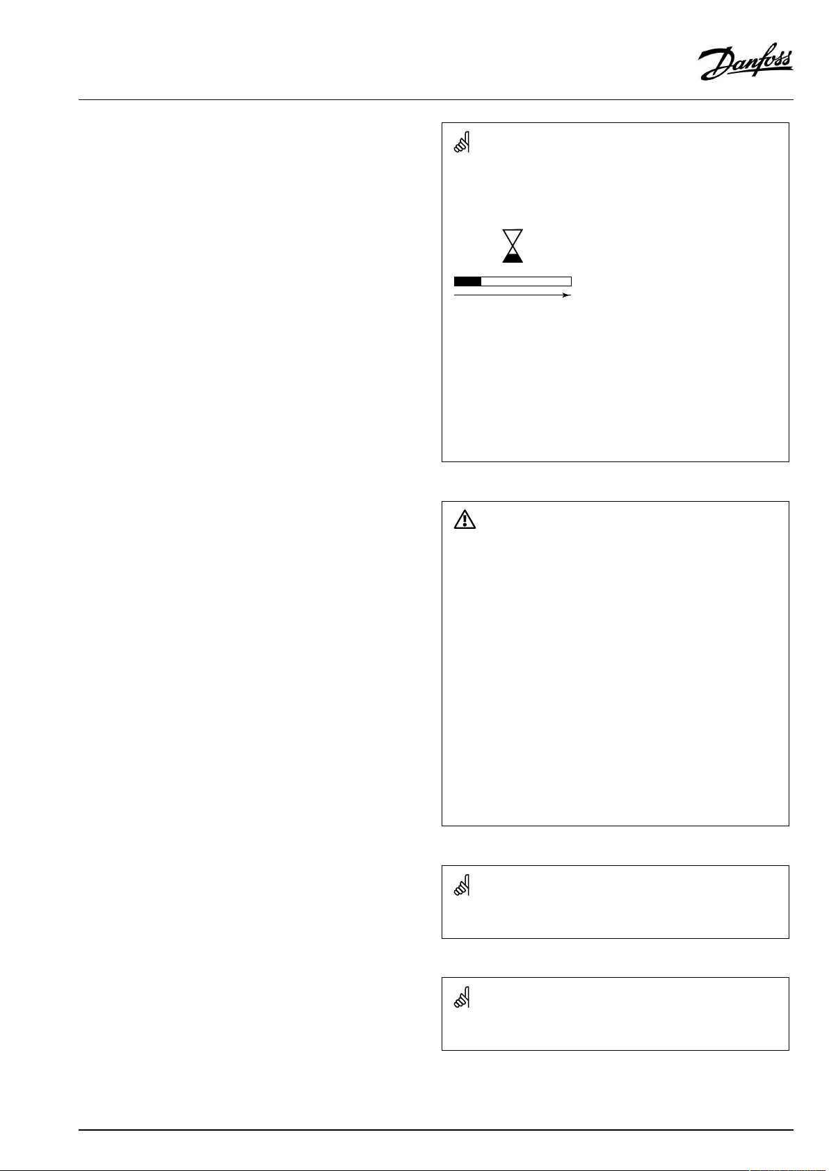
Automaticupdateofcontrollersoftware(firmware):
Thesoftwareofthecontrollerisupdatedautomaticallywhenthekey
isinserted(asofcontrollerversion1.11(ECL210/310)andversion
1.58(ECL296)).Thefollowinganimationwillbeshownwhenthe
softwareisbeingupdated:
Progressbar
Duringupdate:
•DonotremovetheKEY
Ifthekeyisremovedbeforethehour-glassisshown,youhave
tostartafresh.
•Donotdisconnectthepower
Ifthepowerisinterruptedwhenthehour-glassisshown,the
controllerwillnotwork.
•Manualupdateofcontrollersoftware(firmware):
Seethesection"Automatic/manualupdateoffirmware"
SafetyNote
Toavoidinjuryofpersonsanddamagestothedevice,itisabsolutely
necessarytoreadandobservetheseinstructionscarefully.
Necessaryassembly,start-up,andmaintenanceworkmustbe
performedbyqualifiedandauthorizedpersonnelonly.
Locallegislationsmustberespected.Thiscomprisesalsocable
dimensionsandtypeofisolation(doubleisolatedat230V).
AfusefortheECLComfortinstallationismax.10Atypically.
TheambienttemperaturerangesforECLComfortinoperationare:
ECLComfort210/310:0-55°C
ECLComfort296:0-45°C.
Exceedingthetemperaturerangecanresultinmalfunctions.
Installationmustbeavoidedifthereisariskforcondensation(dew).
Thewarningsignisusedtoemphasizespecialconditionsthatshould
betakenintoconsideration.
Thissymbolindicatesthatthisparticularpieceofinformationshould
bereadwithspecialattention.
Applicationkeysmightbereleasedbeforealldisplaytextsare
translated.InthiscasethetextisinEnglish.
AQ146286475947en-010601
©Danfoss|2021.06|3
Page 4
OperatingGuideECLComfort210/296/310,applicationA214/A314
AsthisOperatingGuidecoversseveralsystemtypes,specialsystem
settingswillbemarkedwithasystemtype.Allsystemtypesareshown
inthechapter:'Identifyingyoursystemtype'.
°C(degreesCelsius)isameasuredtemperaturevaluewhereasK
(Kelvin)oftenisusedfortemperaturedifferences.
TheIDno.isuniquefortheselectedparameter.
ExampleFirstdigitSeconddigitLastthreedigits
1117411174
-
Circuit1Parameterno.
12174
IfanIDdescriptionismentionedmorethanonce,itmeansthatthere
arespecialsettingsforoneormoresystemtypes.Itwillbemarked
withthesystemtypeinquestion(e.g.12174-A266.9).
ParametersindicatedwithanIDno.like"1x607"meanauniversal
parameter.
xstandsforcircuit/parametergroup.
1
-
DisposalNote
Thissymbolontheproductindicatesthatitmaynot
bedisposedofashouseholdwaste.
Itmustbehandedovertotheapplicabletake-back
schemefortherecyclingofelectricalandelectronic
equipment.
•Disposeoftheproductthroughchannelsprovided
forthispurpose.
•Complywithalllocalandcurrentlyapplicablelaws
andregulations.
2
Circuit2Parameterno.
174
4|©Danfoss|2021.06
AQ146286475947en-010601
Page 5
OperatingGuideECLComfort210/296/310,applicationA214/A314
2.0Installation
2.1Beforeyoustart
TheApplicationKeyA214containsseveralapplications,mainly
relatedtoventilationsystemswithheatingorcoolingora
combinationofthese.TheapplicationsintheA214keyofferawide
rangeofpossibilities(seetheexamples).
TheapplicationA214.1isveryflexible.Thesearethebasic
principles:
Coolingwithroomtemperaturecontrol:
Typically,theairducttemperatureisadjustedaccordingtoyour
requirements.TheairducttemperaturesensorS3isthemost
importantsensor.ThedesiredtemperatureatS3issetintheECL
Comfortcontrollerasthe'Desiredbalancetemperature'.
ThemotorizedcontrolvalveM2(controllingthecoolingtransfer)is
openedgraduallywhentheducttemperatureishigherthanthe
desiredducttemperatureandviceversa.
Roomtemperature:
Ifthemeasuredroomtemperature(S4orECA30)doesnotequal
thedesiredroomtemperature,thedesiredtemperatureatS3can
beadjusted.
Bymeansofaweekschedule(upto3‘Comfort’periods/day),the
coolingcircuitcanbein‘Comfort’or‘Saving’mode(twodifferent
temperaturevaluesfordesiredroomtemperature).
Thedesiredroomtemperaturedeterminesacorrectionofthe
desiredtemperatureatS3.
Iftheroomtemperatureisnotmeasured,thedesiredroom
temperatureequals(willbe)thedesiredtemperatureatS3.Inthis
case,thesettingofthe'Balancetemperature'isnotconsidered(or:
hasnoinfluence).
Thefan(F1)isON/OFFcontrolledaccordingtothescheduleand
coolingdemand.Thedamper(P2)isON/OFFcontrolledaccording
toschedule.Thecirculationpump(X3)isON/OFFcontrolled
accordingtocoolingdemand.
Returntemperature(optional):
Ifthemeasuredreturntemperature(S5)doesnotequalthe
limitationvalue(typically,thereturntemperaturebecomeslower
thanthelimitationvalue),thedesiredtemperatureatS3canbe
adjusted(typicallytoahighervalue).Thisresultsinagradual
closingofthemotorizedcontrolvalve.
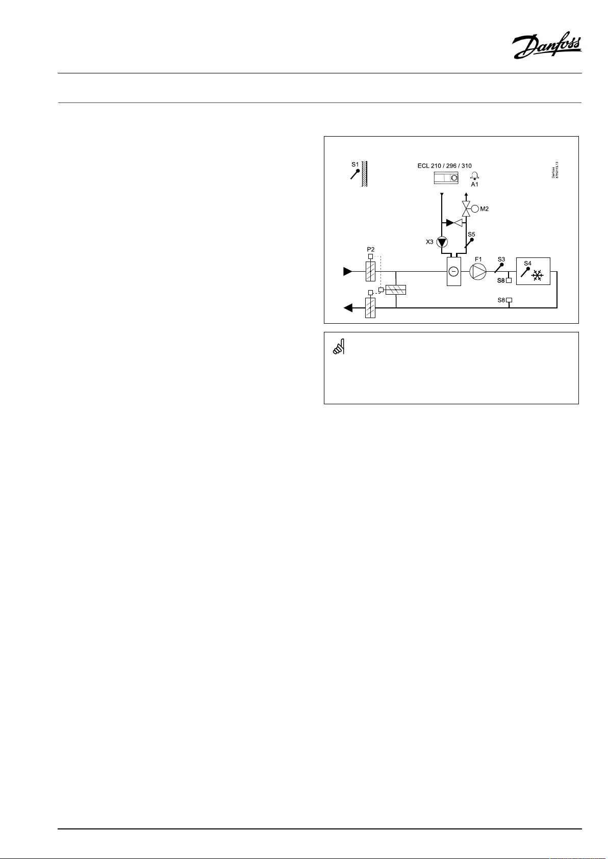
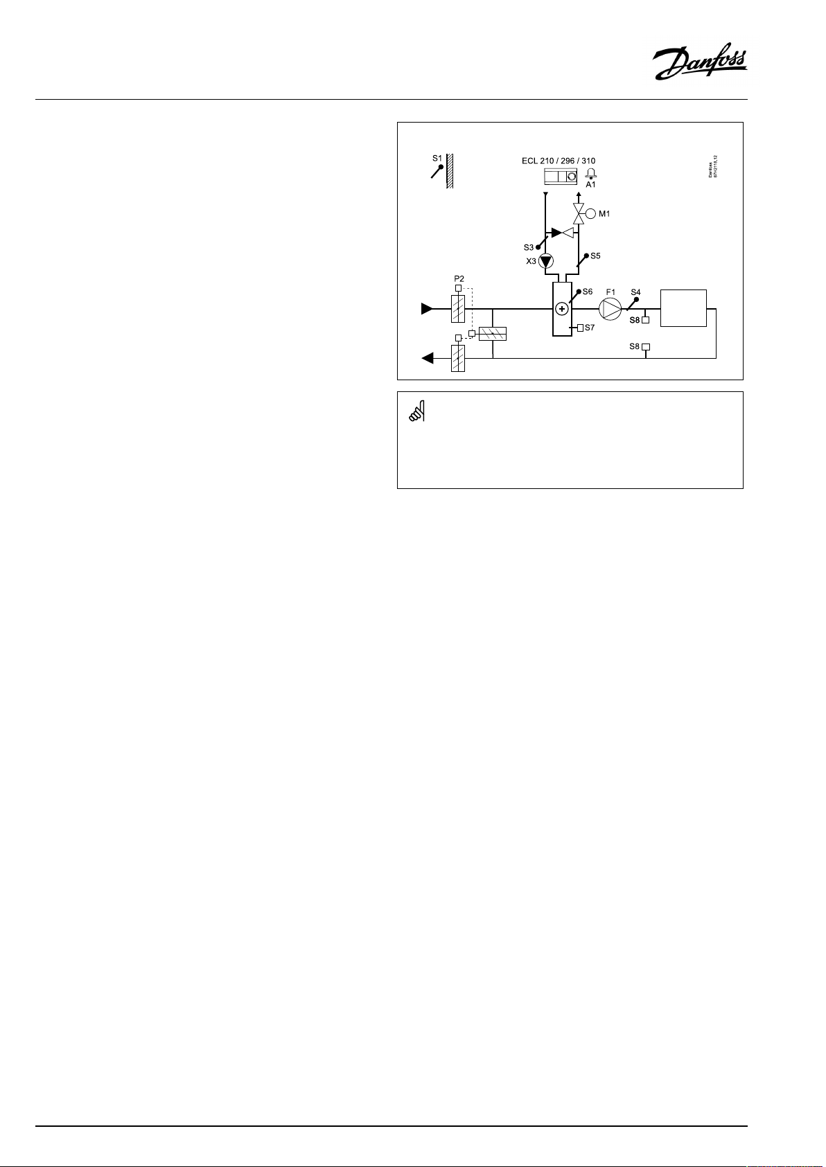
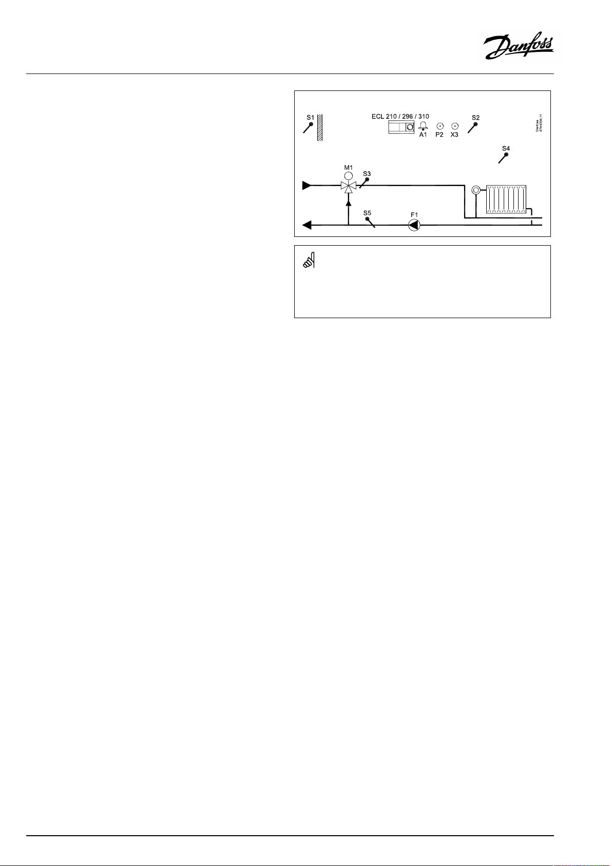
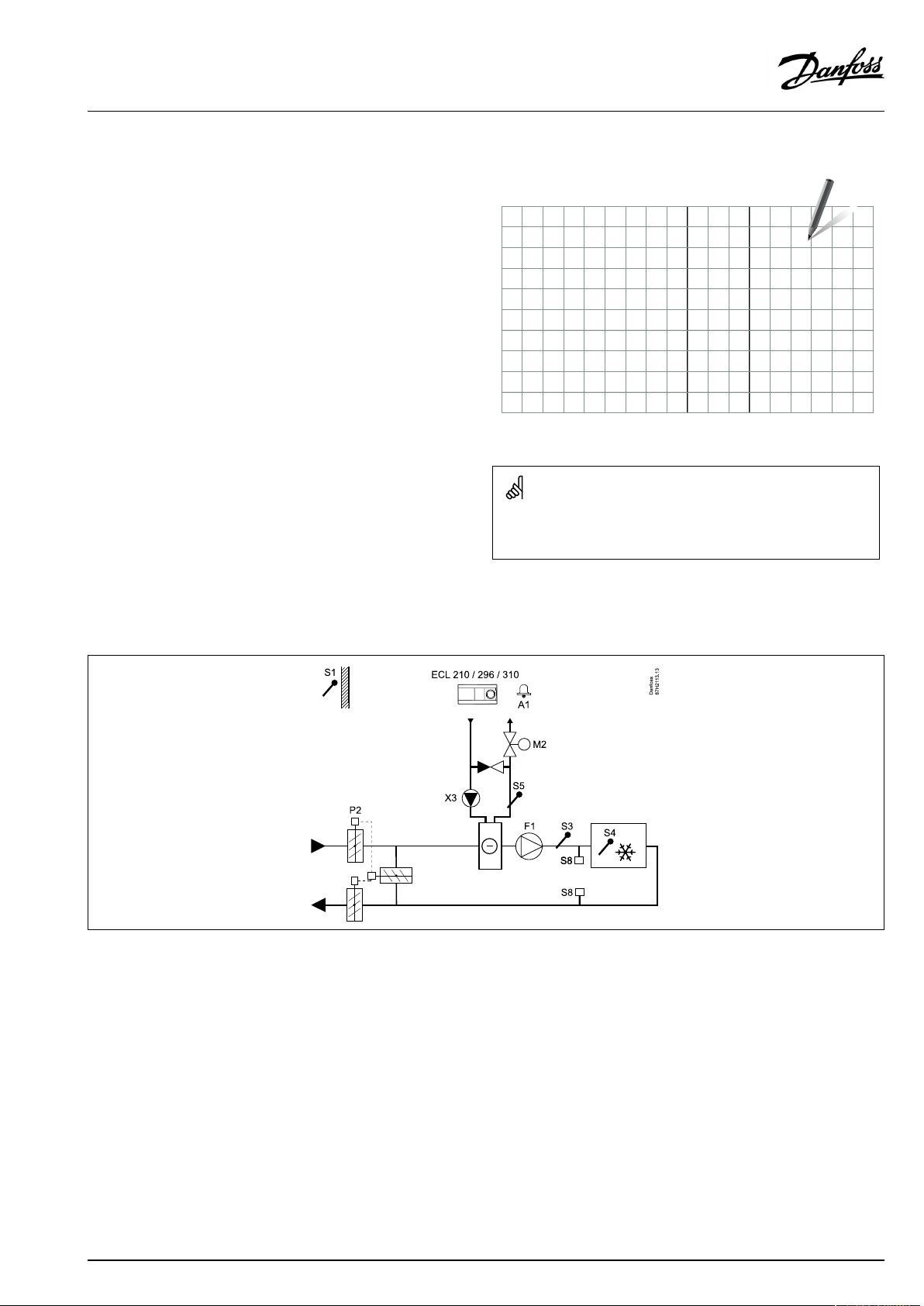
TypicalA214.1application:
Theshowndiagramisafundamentalandsimplifiedexampleanddoes
notcontainallcomponentsthatarenecessaryinasystem.
AllnamedcomponentsareconnectedtotheECLComfortcontroller.
Listofcomponents:
ECL210/310
S1
S2
S3Ducttemperaturesensor
S4
S5
S8
F1
P2
X3
M2
A1
ElectroniccontrollerECLComfort210or310
Outdoortemperaturesensor
(Optional)Compensationtemperaturesensor(not
illustrated)
(Optional)Roomtemperaturesensor*
(Optional)Returntemperaturesensor
(Optional)Firethermostat
Fan(ON/OFF)
Damper(ON/OFF)
Circulationpump(ON/OFF)
Motorizedcontrolvalve,cooling(3-point
controlled)
Alarm
*Alternative:ECA30
Asimplefrostprotection(viaS5)canbeestablished.Furthermore,
itisexpectedthatthecoolingexchanger(fancoil)circuitcontains
brine.
Foradescriptionofalarmsandcompensationtemperature,please
readthesection‘A214andA314ingeneral’ .
AQ146286475947en-010601
©Danfoss|2021.06|5
Page 6
OperatingGuideECLComfort210/296/310,applicationA214/A314
TheapplicationsA214.2andA214.3areveryflexibleandalmost
identical.Thesearethebasicprinciples:
A214.2:Heatingwithducttemperaturecontrol
A214.3:Heatingwithroomtemperaturecontrol
Typically,theheatingtemperatureisadjustedaccordingtoyour
requirements.ThetemperaturesensorS3isthemostimportant
sensor.ThedesiredtemperatureatS3issetintheECLComfort
controllerasthe'Desiredbalancetemperature' .
ThemotorizedcontrolvalveM1(controllingtheheatingsupply
temperature)isopenedgraduallywhentheS3temperatureis
lowerthanthedesiredS3temperatureandviceversa.
S4temperature:
IfthemeasuredS4temperaturedoesnotequalthedesiredS4
temperature,thedesiredtemperatureatS3canbeadjusted.
Bymeansofaweekschedule(upto3‘Comfort’periods/day),the
heatingcircuitcanbein‘Comfort’or‘Saving’mode(twodifferent
temperaturevaluesfordesiredS4temperature).ThedesiredS4
temperaturedeterminesacorrectionofthedesiredtemperature
atS3.
Thefan(F1)isON/OFFcontrolledaccordingtothescheduleand
heatingdemand.Thedamper(P2)isON/OFFcontrolledaccording
toschedule.Thecirculationpump(X3)isON/OFFcontrolled
accordingtoheatingdemand.
Foradescriptionofalarms,compensationtemperature,return
temperaturelimitation(S5)andfrostprotection(S6andS7),please
readthesection‘A214andA314ingeneral’ .
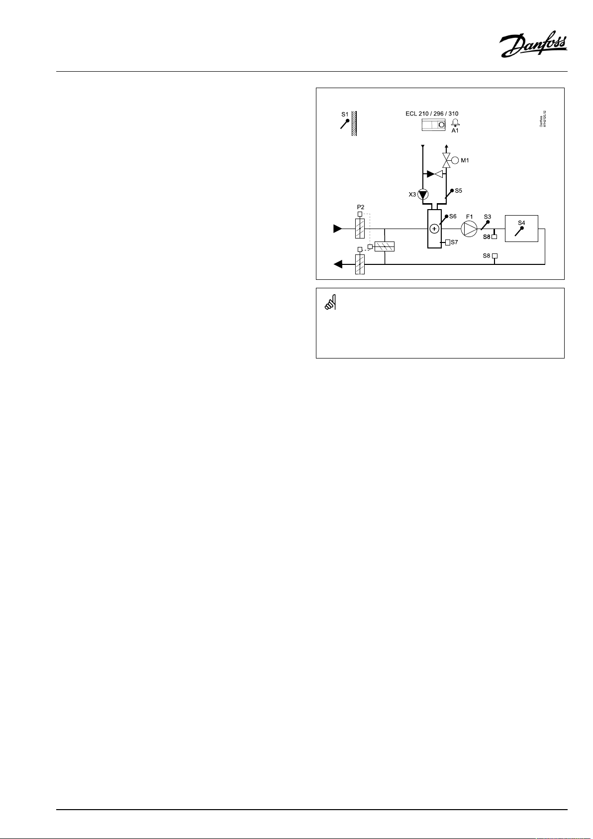
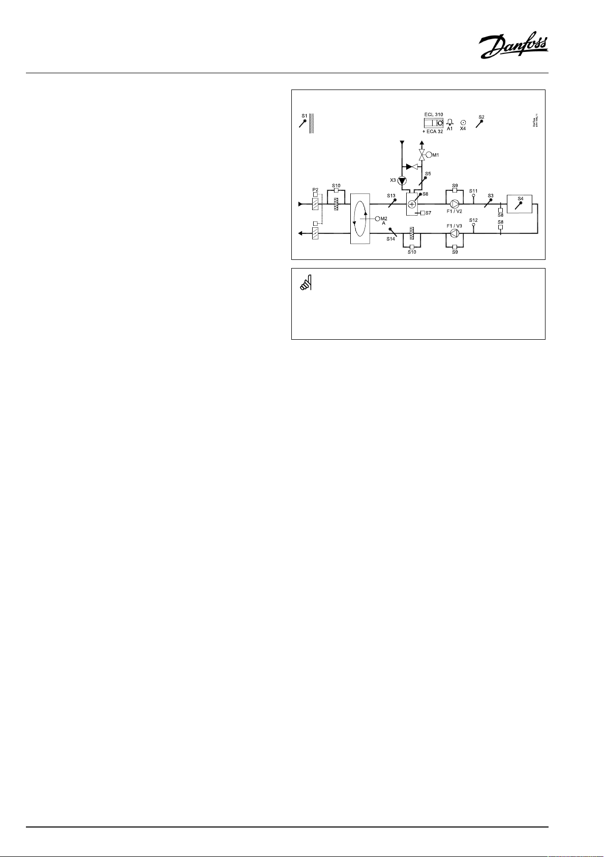
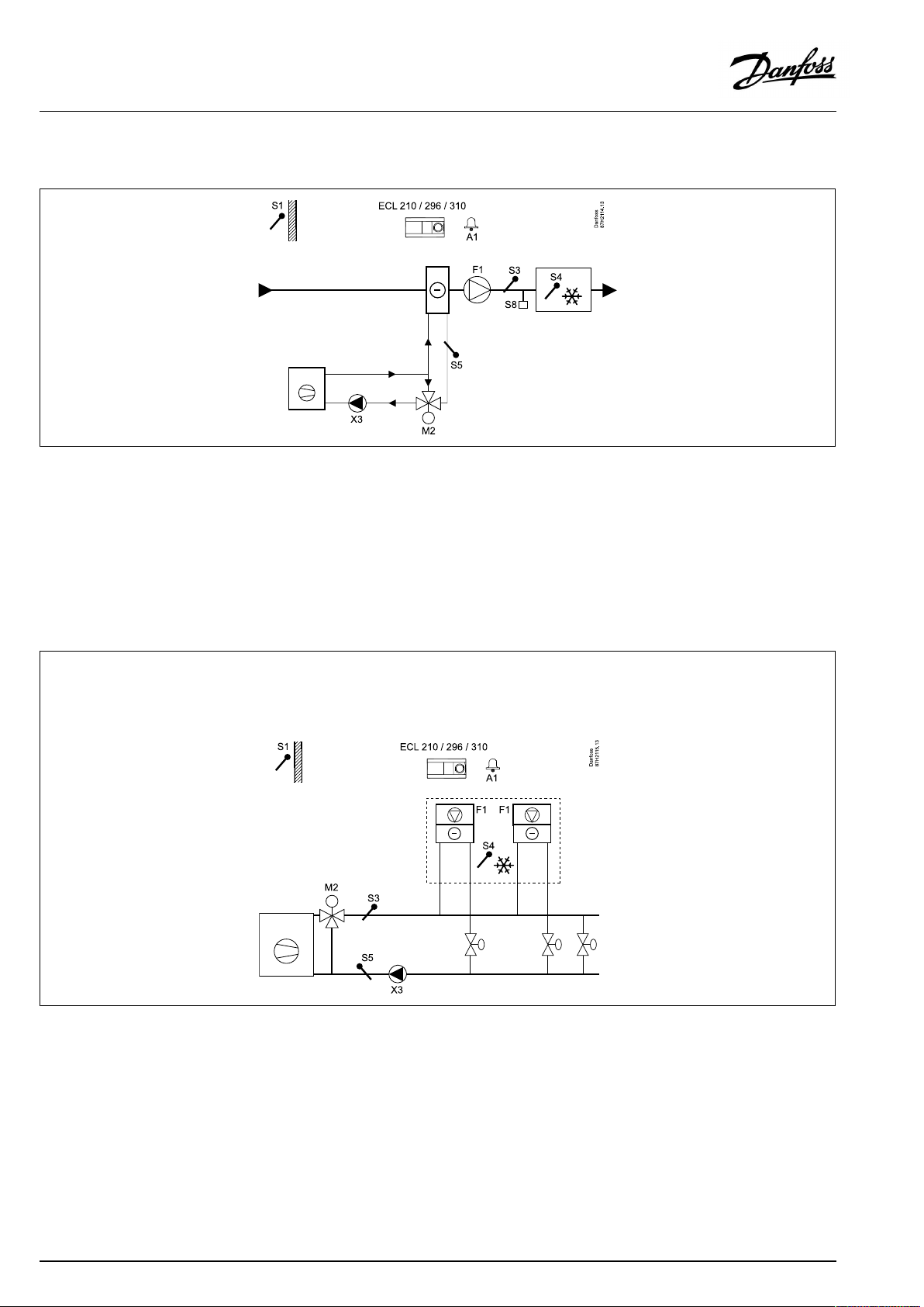
TypicalA214.2application:
Theshowndiagramisafundamentalandsimplifiedexampleanddoes
notcontainallcomponentsthatarenecessaryinasystem.
AllnamedcomponentsareconnectedtotheECLComfortcontroller.
Listofcomponents:
ECL210/310
S1
S2
ElectroniccontrollerECLComfort210or310
Outdoortemperaturesensor
(Optional)Compensationtemperaturesensor(not
illustrated)
S3
Flowtemperaturesensor
S4Ducttemperaturesensor
S5
S6
S7
S8
F1
P2
X3
M1
A1
(Optional)Returntemperaturesensor
(Optional)Frosttemperaturesensor
(Optional)Frostthermostat
(Optional)Firethermostat
Fan(ON/OFF)
Damper(ON/OFF)
Circulationpump(ON/OFF)
Motorizedcontrolvalve,heating(3-pointcontrolled)
Alarm
6|©Danfoss|2021.06
AQ146286475947en-010601
Page 7
OperatingGuideECLComfort210/296/310,applicationA214/A314
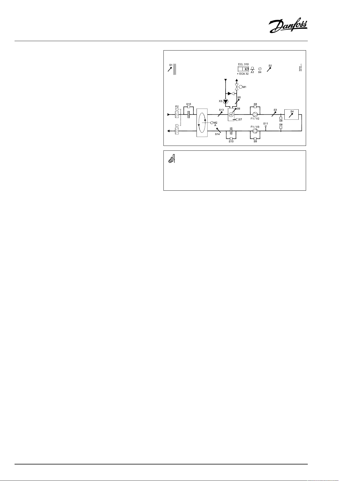
TypicalA214.3application:
Theshowndiagramisafundamentalandsimplifiedexampleanddoes
notcontainallcomponentsthatarenecessaryinasystem.
AllnamedcomponentsareconnectedtotheECLComfortcontroller.
Listofcomponents:
ECL210/310
S1
S2
ElectroniccontrollerECLComfort210or310
Outdoortemperaturesensor
(Optional)Compensationtemperaturesensor(not
illustrated)
S3Ducttemperaturesensor
S4
S5
S6
S7
S8
F1
P2
X3
M1
A1
Roomtemperaturesensor*
(Optional)Returntemperaturesensor
(Optional)Frosttemperaturesensor
(Optional)Frostthermostat
(Optional)Firethermostat
Fan(ON/OFF)
Damper(ON/OFF)
Circulationpump(ON/OFF)
Motorizedcontrolvalve,heating(3-pointcontrolled)
Alarm
*Alternative:ECA30
AQ146286475947en-010601
©Danfoss|2021.06|7
Page 8
OperatingGuideECLComfort210/296/310,applicationA214/A314
TheapplicationA214.4isveryflexible.Thesearethebasic
principles:
Heating/coolingwithairducttemperaturecontrol
Typically,theheating/coolingtemperatureisadjustedaccording
toyourrequirements.
TheflowtemperaturesensorS3intheheatingcircuitisthemost
importantsensor.ThedesiredtemperatureatS3issetintheECL
Comfortcontrollerasthe'Desiredbalancetemperature'.
ThemotorizedcontrolvalveM1(controllingtheheating
temperature)isopenedgraduallywhentheflowtemperatureis
lowerthanthedesiredbalancetemperatureandviceversa.
Atcooling,themotorizedcontrolvalveM2controlsthecooling
temperatureatS4.
Airducttemperature:
AtoolowairducttemperatureS4willactivatetheheatingcircuit
M1,whereasatoohighairducttemperaturewillactivatethe
coolingcircuitM2.
Atheatingdemand,theairducttemperatureS4canadjustthe
desiredtemperatureatS3.Atcoolingdemand,theairduct
temperatureS4iscontrolledaccordingtothedesiredairduct
temperature.A"Deadzone"(=numberofdegrees)canbeset
inordertoavoidunstableshiftsbetweenheatingandcooling
operation.
Bymeansofaweekschedule(upto3‘Comfort’periods/day),the
heating/coolingcircuitcanbein‘Comfort’or‘Saving’mode(two
differenttemperaturevaluesfordesiredairducttemperature).
In'Saving'modethedesiredairducttemperaturedeterminesa
correctionofthedesiredtemperatureatS3inheatingmode.In
coolingmodethecoolingisOFFduring'Saving' .
ThefanF1isON/OFFcontrolledaccordingtothescheduleand
heating/coolingdemand.ThedamperP2isON/OFFcontrolled
accordingtoschedule.ThecirculationpumpX3isON/OFF
controlledaccordingtoheatingdemand.
Foradescriptionofalarms,compensationtemperature,return
temperaturelimitation(S5)andfrostprotection(S6andS7),please
readthesection‘A214andA314ingeneral’ .
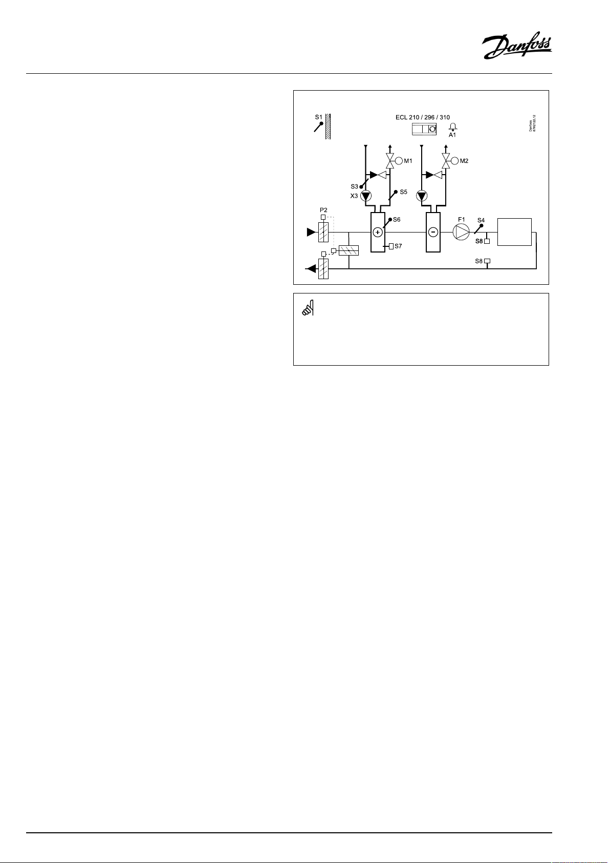
TypicalA214.4application:
Theshowndiagramisafundamentalandsimplifiedexampleanddoes
notcontainallcomponentsthatarenecessaryinasystem.
AllnamedcomponentsareconnectedtotheECLComfortcontroller.
Listofcomponents:
ECL210/310
S1
S2
ElectroniccontrollerECLComfort210or310
Outdoortemperaturesensor
(Optional)Compensationtemperaturesensor(not
illustrated)
S3
S4
S5
S6
S7
S8
F1
P2
X3
M1
Heatingtemperaturesensor
Airducttemperaturesensor
(Optional)Returntemperaturesensor
(Optional)Frosttemperaturesensor
(Optional)Frostthermostat
(Optional)Firethermostat
Fan(ON/OFF)
Damper(ON/OFF)
Circulationpump,heating(ON/OFF)
Motorizedcontrolvalve,heating(3-point
controlled)
M2
A1
Motorizedcontrolvalve,cooling(3-pointcontrolled)
Alarm
8|©Danfoss|2021.06
AQ146286475947en-010601
Page 9
OperatingGuideECLComfort210/296/310,applicationA214/A314
TheapplicationA214.5isveryflexible.Thesearethebasic
principles:
Heating/coolingwithroomtemperaturecontrol
Typically,theheating/coolingtemperatureisadjustedaccording
toyourrequirements.
ThetemperaturesensorS3intheairductisthemostimportant
sensor.ThedesiredtemperatureatS3issetintheECLComfort
controllerasthe'Desiredbalancetemperature' .
ThemotorizedcontrolvalveM1(controllingtheheating
temperature)isopenedgraduallywhentheairducttemperatureis
lowerthanthedesiredbalancetemperatureandviceversa.
Atcooling,themotorizedcontrolvalveM2controlsthecooling
temperature.
Roomtemperature:
AtoolowroomtemperatureS4willactivatetheheatingcircuitM1,
whereasatoohighroomtemperaturewillactivatethecooling
circuitM2.A"Deadzone"(=numberofdegrees)canbesetinorder
toavoidunstableshiftsbetweenheatingandcoolingoperation.
Atheating/coolingdemand,theroomtemperatureS4canadjust
thedesiredtemperatureatS3.
Bymeansofaweekschedule(upto3‘Comfort’periods/day),the
heating/coolingcircuitcanbein‘Comfort’or‘Saving’mode(two
differenttemperaturevaluesfordesiredroomtemperature).
In'Saving'modethedesiredroomtemperaturedeterminesa
correctionofthedesiredtemperatureatS3inheatingmode.In
coolingmodethecoolingisOFFduring'Saving' .
ThefanF1isON/OFFcontrolledaccordingtothescheduleand
heating/coolingdemand.ThedamperP2isON/OFFcontrolled
accordingtoschedule.ThecirculationpumpX3isON/OFF
controlledaccordingtoheatingdemand.
Foradescriptionofalarms,compensationtemperature,return
temperaturelimitation(S5)andfrostprotection(S6andS7),please
readthesection‘A214andA314ingeneral’ .
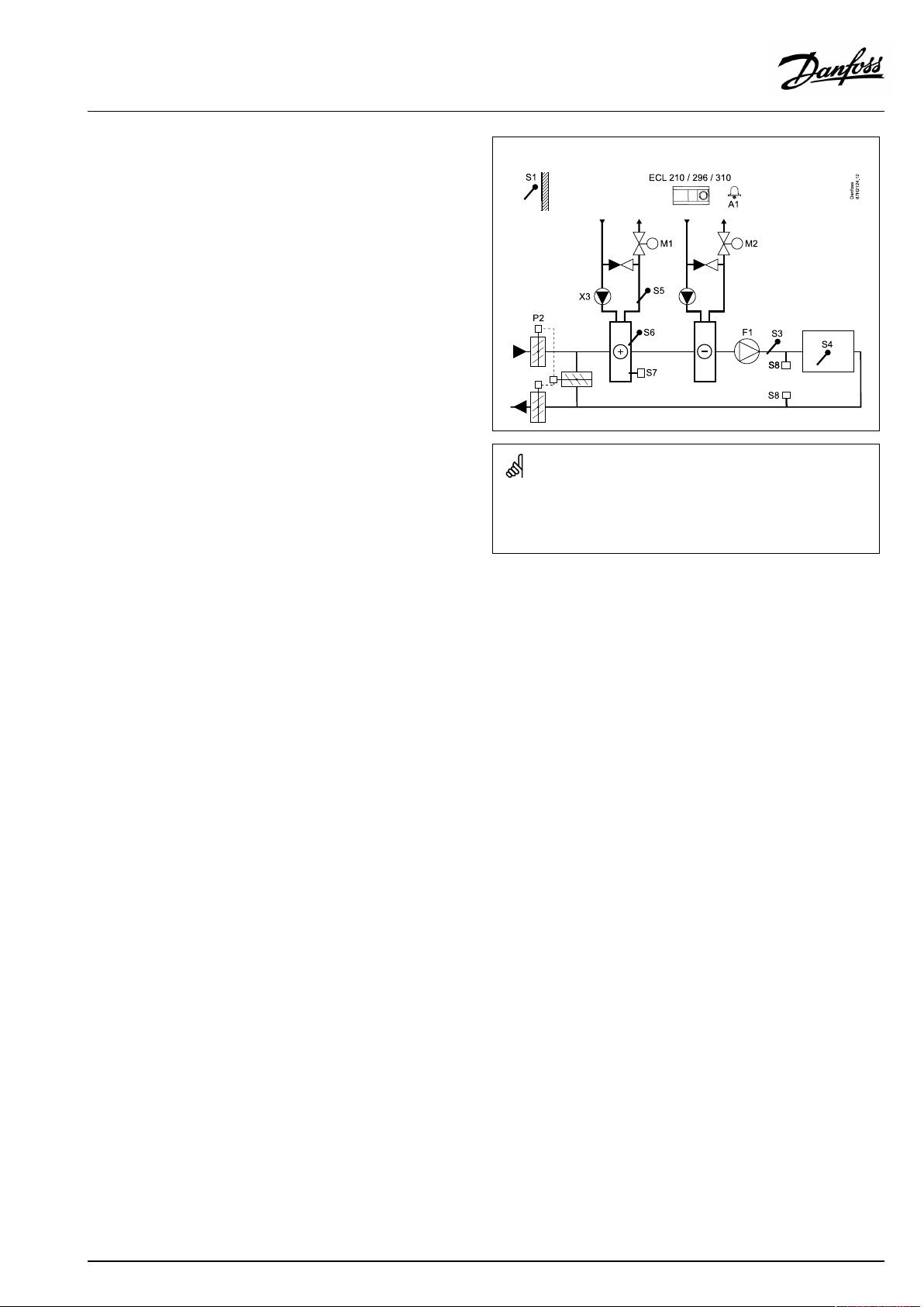
TypicalA214.5application:
Theshowndiagramisafundamentalandsimplifiedexampleanddoes
notcontainallcomponentsthatarenecessaryinasystem.
AllnamedcomponentsareconnectedtotheECLComfortcontroller.
Listofcomponents:
ECL210/310
S1
S2
ElectroniccontrollerECLComfort210or310
Outdoortemperaturesensor
(Optional)Compensationtemperaturesensor(not
illustrated)
S3Ducttemperaturesensor
S4
S5
S6
S7
S8
F1
P2
X3
M1
M2
A1
Roomtemperaturesensor*
(Optional)Returntemperaturesensor
(Optional)Frosttemperaturesensor
(Optional)Frostthermostat
(Optional)Firethermostat
Fan(ON/OFF)
Damper(ON/OFF)
Circulationpump,heating(ON/OFF)
Motorizedcontrolvalve,heating(3-pointcontrolled)
Motorizedcontrolvalve,cooling(3-pointcontrolled)
Alarm
*Alternative:ECA30
AQ146286475947en-010601
©Danfoss|2021.06|9
Page 10
OperatingGuideECLComfort210/296/310,applicationA214/A314
TheapplicationA214.6isveryflexible.Thesearethebasic
principles:
Heatingwithroomtemperaturecontrol:
Typically,theflowtemperatureisadjustedaccordingtoyour
requirements.TheflowtemperaturesensorS3isthemost
importantsensor.ThedesiredtemperatureatS3issetintheECL
Comfortcontrollerasthe'Desiredbalancetemperature'.
ThemotorizedcontrolvalveM1isopenedgraduallywhenthe
flowtemperatureislowerthanthedesiredflowtemperatureand
viceversa.
Roomtemperature:
Ifthemeasuredroomtemperature(S4orECA30)doesnotequal
thedesiredroomtemperature,thedesiredtemperatureatS3can
beadjusted.
Bymeansofaweekschedule(upto3‘Comfort’periods/day),
theheatingcircuitcanbein‘Comfort’or‘Saving’mode(two
differenttemperaturevaluesfordesiredroomtemperature).The
desiredroomtemperaturedeterminesacorrectionofthedesired
temperatureatS3.
Thecirculationpump(F1)isON/OFFcontrolledaccordingtothe
Schedule1.Theaccessory(P2)isON/OFFcontrolledaccording
toSchedule1or2.
Foradescriptionofalarms,compensationtemperature,return
temperaturelimitation(S5),frostprotection(S6andS7)andfire
alarmpleasereadthesection‘A214andA314ingeneral’ .
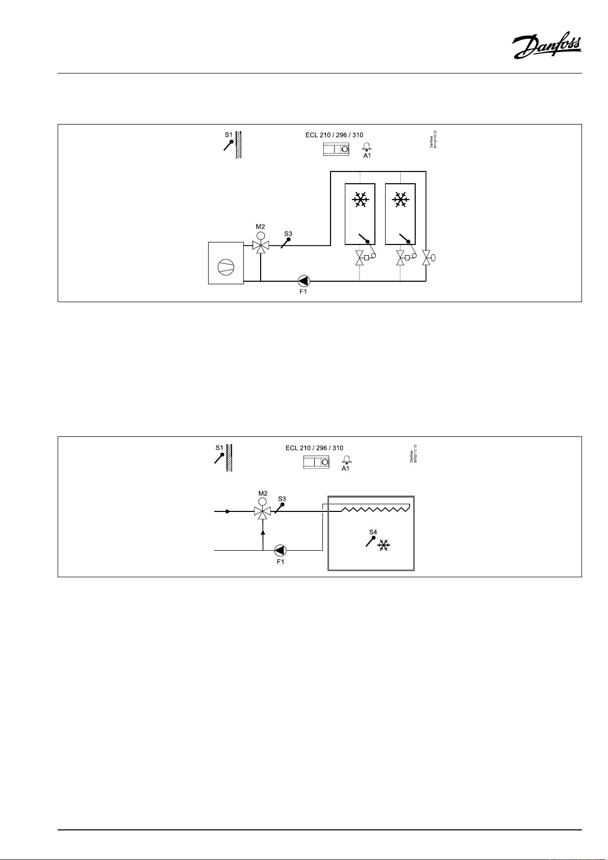
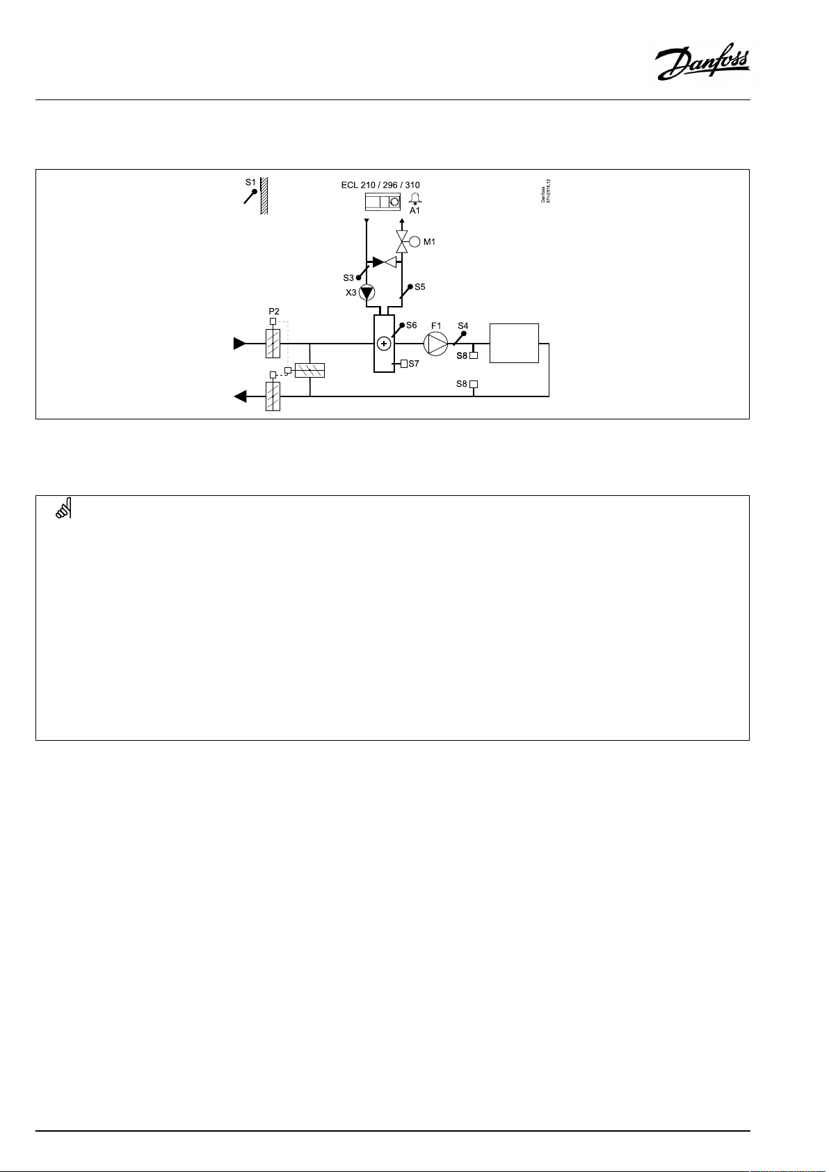
TypicalA214.6application:
Theshowndiagramisafundamentalandsimplifiedexampleanddoes
notcontainallcomponentsthatarenecessaryinasystem.
AllnamedcomponentsareconnectedtotheECLComfortcontroller.
Listofcomponents:
ECL210/310
S1
S2
S3
S4
S5
S6
S7
S8
F1
P2
X3
M1
A1
ElectroniccontrollerECLComfort210or310
Outdoortemperaturesensor
(Optional)Compensationtemperaturesensor
Flowtemperaturesensor
Roomtemperaturesensor*
(Optional)Returntemperaturesensor
(Optional)Frosttemperaturesensor(notillustrated)
(Optional)Frostthermostat(notillustrated)
(Optional)Firethermostat(notillustrated)
Circulationpump(ON/OFF)
Accessoryoutput(ON/OFF)
Optionaloutput(ON/OFF)
Motorizedcontrolvalve,heating(3-pointcontrolled)
Alarm
*Alternative:ECA30
10|©Danfoss|2021.06
AQ146286475947en-010601
Page 11
OperatingGuideECLComfort210/296/310,applicationA214/A314
TheapplicationA314.1isveryflexible.Thesearethebasic
principles:
Heatingand(passive)coolingwithairducttemperature
control
Typically,theheating/coolingtemperatureisadjustedaccording
toyourrequirements.TheflowtemperaturesensorS3isthemost
importantsensor.ThedesiredtemperatureatS3issetintheECL
Comfortcontrollerasthe'Desiredbalancetemperature'.
ThemotorizedcontrolvalveM1(controllingtheheating
temperature)isopenedgraduallywhentheflowtemperatureis
lowerthanthedesiredtemperatureandviceversa.Atcooling,
themotorizeddamperM2controlsthecoolingtemperature.The
coolingsectioncanbepassive(re-circulation)oractive.
Airducttemperature:
AtoolowtemperatureatS4willactivatetheheatingcircuit(M1),
whereasatoohighducttemperaturewillactivatethecooling
circuit(M2).
Atheatingdemand,thetemperatureatS4canadjustthedesired
temperatureatS3.Atcoolingdemand,theS4temperatureis
controlledaccordingtothedesiredS4temperature.A"Deadzone"
(=numberofdegrees)canbesetinordertoavoidunstableshifts
betweenheatingandcoolingoperation.
M1is3-pointcontrolled,whereasM2is0-10Vcontrolled.
Bymeansofaweekschedule(upto3‘Comfort’periods/day),the
heating/coolingcircuitcanbein‘Comfort’or‘Saving’mode(two
differenttemperaturevaluesfordesiredairducttemperature).
In'Saving'modethedesiredairducttemperaturedeterminesa
correctionofthedesiredtemperatureatS3inheatingmode.In
coolingmodethecoolingisOFFduring'Saving' .
ThefanF1isON/OFFcontrolledaccordingtothescheduleand
heating/coolingdemand.ThedamperP2isON/OFFcontrolled
accordingtoschedule.ThecirculationpumpX3isON/OFF
controlledaccordingtoheatingdemand.
Foradescriptionofalarms,compensationtemperature,return
temperaturelimitation(S5)andfrostprotection(S6andS7),please
readthesection‘A214andA314ingeneral’ .
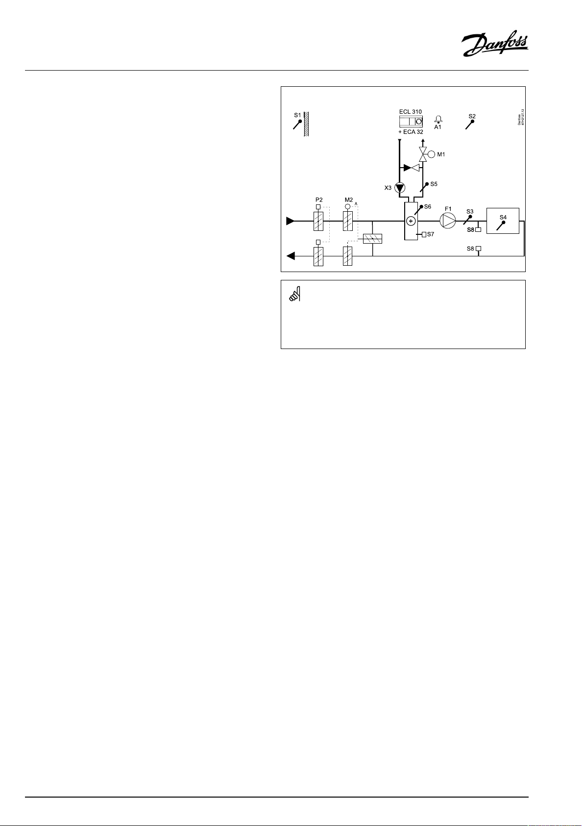
TypicalA314.1application:
Theshowndiagramisafundamentalandsimplifiedexampleanddoes
notcontainallcomponentsthatarenecessaryinasystem.
AllnamedcomponentsareconnectedtotheECLComfortcontroller.
Listofcomponents:
ECL310
ECA32
S1
S2
S3
ElectroniccontrollerECLComfort310
Built-inextensionmodule
Outdoortemperaturesensor
(Optional)Compensationtemperaturesensor
Flowtemperaturesensor
S4Ducttemperaturesensor
S5
S6
S7
S8
F1
P2
X3
M1
M2
A1
(Optional)Returntemperaturesensor
(Optional)Frosttemperaturesensor
(Optional)Frostthermostat
(Optional)Firethermostat
Fan(ON/OFF)
Damper(ON/OFF)
Circulationpump,heating(ON/OFF)
Motorizedcontrolvalve,heating(3-pointcontrolled)
Motorizeddamper(0-10voltcontrolled)
Alarm
AQ146286475947en-010601
©Danfoss|2021.06|11
Page 12
OperatingGuideECLComfort210/296/310,applicationA214/A314
TheapplicationA314.2isveryflexible.Thesearethebasic
principles:
Heatingand(passive)coolingwithroomtemperaturecontrol
Typically,theheating/coolingtemperatureisadjustedaccording
toyourrequirements.TheairducttemperaturesensorS3isthe
mostimportantsensor.ThedesiredtemperatureatS3issetinthe
ECLComfortcontrollerasthe'Desiredbalancetemperature' .
ThemotorizedcontrolvalveM1(controllingtheheating
temperature)isopenedgraduallywhentheairducttemperature
islowerthanthedesiredtemperatureandviceversa.Atcooling,
themotorizeddamperM2controlsthecoolingtemperature.The
coolingsectioncanbepassive(re-circulation)oractive.
Roomtemperature:
AtoolowtemperatureatS4willactivatetheheatingcircuit(M1),
whereasatoohighducttemperaturewillactivatethecooling
circuit(M2).A"Deadzone"(=numberofdegrees)canbeset
inordertoavoidunstableshiftsbetweenheatingandcooling
operation.
Atheating/coolingdemand,thetemperatureatS4canadjust
thedesiredtemperatureatS3.
M1is3-pointcontrolled,whereasM2is0-10Vcontrolled.
Bymeansofaweekschedule(upto3‘Comfort’periods/day),the
heating/coolingcircuitcanbein‘Comfort’or‘Saving’mode(two
differenttemperaturevaluesfordesiredroomtemperature).
In'Saving'modethedesiredroomtemperaturedeterminesa
correctionofthedesiredtemperatureatS3inheatingmode.In
coolingmodethecoolingisOFFduring'Saving' .
ThefanF1isON/OFFcontrolledaccordingtothescheduleand
heating/coolingdemand.ThedamperP2isON/OFFcontrolled
accordingtoschedule.ThecirculationpumpX3isON/OFF
controlledaccordingtoheatingdemand.
Foradescriptionofalarms,compensationtemperature,return
temperaturelimitation(S5)andfrostprotection(S6andS7),please
readthesection‘A214andA314ingeneral’ .
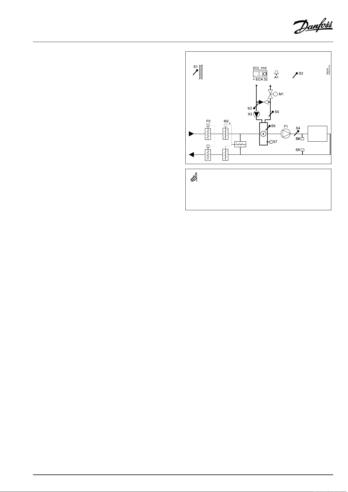
TypicalA314.2application:
Theshowndiagramisafundamentalandsimplifiedexampleanddoes
notcontainallcomponentsthatarenecessaryinasystem.
AllnamedcomponentsareconnectedtotheECLComfortcontroller.
Listofcomponents:
ECL310
ECA32
S1
S2
ElectroniccontrollerECLComfort310
Built-inextensionmodule
Outdoortemperaturesensor
(Optional)Compensationtemperaturesensor
S3Ducttemperaturesensor
S4
S5
S6
S7
S8
F1
P2
X3
M1
M2
A1
Roomtemperaturesensor*
(Optional)Returntemperaturesensor
(Optional)Frosttemperaturesensor
(Optional)Frostthermostat
(Optional)Firethermostat
Fan(ON/OFF)
Damper(ON/OFF)
Circulationpump,heating(ON/OFF)
Motorizedcontrolvalve,heating(3-pointcontrolled)
Motorizeddamper(0-10voltcontrolled)
Alarm
*Alternative:ECA30
12|©Danfoss|2021.06
AQ146286475947en-010601
Page 13
OperatingGuideECLComfort210/296/310,applicationA214/A314
TheapplicationA314.3isveryflexible.Thesearethebasic
principles:
Heatingwithroomtemperaturecontrol
Typically,theairducttemperatureisadjustedaccordingtoyour
requirements.TheairducttemperaturesensorS3isthemost
importantsensor.ThedesiredtemperatureatS3issetintheECL
Comfortcontrollerasthe'Desiredbalancetemperature'.
ThemotorizedcontrolvalveM1(controllingtheheating
temperature)isopenedgraduallywhentheairductemperatureis
lowerthanthedesiredairducttemperatureandviceversa.
Roomtemperature:
Iftheroomtemperature(S4orECA30)doesnotequalthedesired
roomtemperature,thedesiredtemperatureatS3canbeadjusted.
Bymeansofaweekschedule(upto3‘Comfort’periods/day),the
heatingcircuitcanbein‘Comfort’or‘Saving’mode(twodifferent
temperaturevaluesfordesiredroomtemperature).
In'Saving'modethedesiredroomtemperaturedeterminesa
correctionofthedesiredtemperatureatS3.
ThefanF1isON/OFFcontrolledaccordingtothescheduleand
heatingdemand.ThedamperP2isON/OFFcontrolledaccording
toschedule.ThecirculationpumpX3isON/OFFcontrolled
accordingtoheatingdemand.
Variablefanspeed(optional):
ThefanV1canbespeedcontrolledinrelationtothemeasured
windspeedS10.Thefanspeedcontrolsignalisa0–10voltsignal,
generatedbytheinternalinput/outputmoduleECA32.Amenu
intheECLComfort310containssettingsforrelationshipbetween
actualwindspeedanddesiredfanspeed.
Foradescriptionofalarms,compensationtemperature,return
temperaturelimitation(S5)andfrostprotection(S6andS7),please
readthesection‘A214andA314ingeneral’ .
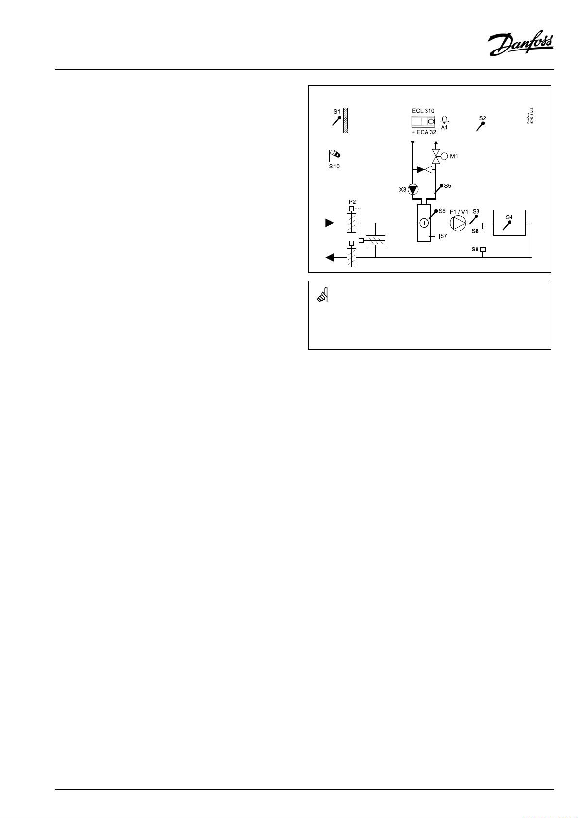
TypicalA314.3application:
Theshowndiagramisafundamentalandsimplifiedexampleanddoes
notcontainallcomponentsthatarenecessaryinasystem.
AllnamedcomponentsareconnectedtotheECLComfortcontroller.
Listofcomponents:
ECL310
ElectroniccontrollerECLComfort310
ECA32
Built-inextensionmodule
S1
Outdoortemperaturesensor
S2
(Optional)Compensationtemperaturesensor
S3Ducttemperaturesensor
S4
Roomtemperaturesensor*
S5
(Optional)Returntemperaturesensor
S6
(Optional)Frosttemperaturesensor
S7
(Optional)Frostthermostat
S8
(Optional)Firethermostat
S10
Windspeedsignal(0-10volt)
F1
Fan(ON/OFF)
P2
Damper(ON/OFF)
X3
Circulationpump,heating(ON/OFF)
M1
Motorizedcontrolvalve,heating(3-pointcontrolled)
M2
Motorizeddamper(0-10voltcontrolled)
V1
Fanspeed(0-10voltcontrolled)
A1
Alarm
*Alternative:ECA30
AQ146286475947en-010601
©Danfoss|2021.06|13
Page 14
OperatingGuideECLComfort210/296/310,applicationA214/A314
TheadvancedheatingapplicationA314.4isveryflexible.These
arethebasicprinciples:
Heatingwithroomtemperatureandairpressurecontrol
Typically,theheatingtemperatureisadjustedaccordingtoyour
requirements.TheairducttemperaturesensorS3isthemost
importantsensor.ThedesiredtemperatureatS3issetintheECL
Comfortcontrollerasthe'Desiredinlettemperature' .
Therecoverycircuit,controlledbyM2,isconsideredasthemain
circuit,whereastheheatingcircuit,controlledbyM1,isthe
supplementarycircuit.
ThemotorizedcontrolvalveM1(controllingtheheating
temperature)isopenedgraduallywhentheS3temperatureis
lowerthanthedesiredS3temperatureandviceversa.
Roomtemperature:
Iftheroomtemperature(S4orECA30)doesnotequalthedesired
roomtemperature,thedesiredtemperatureatS3canbeadjusted.
Bymeansofaweekschedule(upto3‘Comfort’periods/day),the
heatingcircuitcanbein‘Comfort’or‘Saving’mode(twodifferent
temperaturevaluesfordesiredinlettemperatureandtwodifferent
temperaturevaluesfordesiredroomtemperature).
ThefanF1isON/OFFcontrolledaccordingtotheschedule
andheatingdemand.AdamperP2canbeON/OFFcontrolled
accordingtoschedule.ThecirculationpumpX3isON/OFF
controlledaccordingtoheatingdemand.
Airpressurecontrol:
ThefansV2andV3arespeedcontrolledindividuallyinrelationto
desiredpressures(Pascal)atS11andS12.ThesignalsatS11and
S12aremeasuredas0-10voltandconvertedintoPascalintheECL
Comfort310.Furthermore,thespeedofthefanscanbeloweredat
loweroutdoortemperaturesinordertoreducecoldairinlet.
Heatrecovery:
Inordertoutilizeheatfromtheexitairduct,arotating
heat-exchanger,acrossheat-exchangerorafluidbatterycan
becontrolledbyM2.BasedontheoutdoortemperatureS1,the
entryducttemperatureS13andtheexitducttemperatureS14the
recoveryefficiency(in%)canbeindicated.
Nightcooling:
DuringSavingmodeapassivecooling(settingthefansON)canbe
arranged,mainlyunderthefollowingconditions:
•roomtemperatureishigherthandesiredsavingroom
temperature
•outdoortemperatureislowerthantheroomtemperature
TypicalA314.4application:
Theshowndiagramisafundamentalandsimplifiedexampleanddoes
notcontainallcomponentsthatarenecessaryinasystem.
AllnamedcomponentsareconnectedtotheECLComfortcontroller.
Listofcomponents:
ECL310
ECA32
ElectroniccontrollerECLComfort310
Built-inextensionmodule
S1
Outdoortemperaturesensor
S2
(Optional)Compensationtemperaturesensor
S3Ducttemperaturesensor
S4
Roomtemperaturesensor*
S5
(Optional)Returntemperaturesensor
S6
(Optional)Frosttemperaturesensor
S7
(Optional)Frostthermostat
S8
(Optional)Firethermostat
Fanmonitor
S9
S10
Filtermonitor
S11
Inletpressuresensor
S12
Outletpressuresensor
S13
Entryducttemperaturesensor
S14
Exitducttemperaturesensor
F1
Fan(ON/OFF)
P2
Damper(ON/OFF)
X3
Circulationpump,heating(ON/OFF)
X4
Schedule3
P7
Recoverycircuitpump,ON/OFF ,(notillustrated)
P8
Nightdamper,ON/OFF,(notillustrated)
M1
Motorizedcontrolvalve,heating(3-pointcontrolled)
M2
Rotatingheat-exchanger(0-10voltcontrolled)
V2
Fanspeed(0-10voltcontrolled)
V3
Fanspeed(0-10voltcontrolled)
A1
Alarm
*Alternative:ECA30
14|©Danfoss|2021.06
AQ146286475947en-010601
Page 15

OperatingGuideECLComfort210/296/310,applicationA214/A314
Heatingwithroomtemperatureandairpressurecontrol
(continued)
Ventilationduringsavingperiod:
Adesiredreducedpressurecanbeset.
•Roomtemperaturesignalmustbepresent
•ThenightdamperP8willopen
•ThefanV2willoperateatreducedspeed
•ThefanV3isOFF
•P2isOFF
•M2isOFF
Summercut-out:
Whenoutdoortemperatureexceedsaselectablevalue,theheating
systemclosestotally.
M1is3-pointcontrolled,whereasM2is0-10Vcontrolled.
Foradescriptionofalarms,compensationtemperature,return
temperaturelimitation(S5)andfrostprotection(S6andS7),please
readthesection‘A214andA314ingeneral’ .
AQ146286475947en-010601
©Danfoss|2021.06|15
Page 16
OperatingGuideECLComfort210/296/310,applicationA214/A314
TheadvancedheatingapplicationA314.5isveryflexible.These
arethebasicprinciples:
Heatingwithroomtemperatureandairqualitycontrol
Typically,theheatingtemperatureisadjustedaccordingtoyour
requirements.TheairducttemperaturesensorS3isthemost
importantsensor.ThedesiredtemperatureatS3issetintheECL
Comfortcontrollerasthe'Desiredinlettemperature' .
Therecoverycircuit,controlledbyM2,isconsideredasthemain
circuit,whereastheheatingcircuit,controlledbyM1,isthe
supplementarycircuit.
ThemotorizedcontrolvalveM1(controllingtheheating
temperature)isopenedgraduallywhentheS3temperatureis
lowerthanthedesiredS3temperatureandviceversa.
Roomtemperature:
Iftheroomtemperature(S4orECA30)doesnotequalthedesired
roomtemperature,thedesiredtemperatureatS3canbeadjusted.
Bymeansofaweekschedule(upto3‘Comfort’periods/day),the
heatingcircuitcanbein‘Comfort’or‘Saving’mode(twodifferent
temperaturevaluesfordesiredinlettemperatureandtwodifferent
temperaturevaluesfordesiredroomtemperature).
ThefanF1isON/OFFcontrolledaccordingtotheschedule
andheatingdemand.AdamperP2canbeON/OFFcontrolled
accordingtoschedule.ThecirculationpumpX3isON/OFF
controlledaccordingtoheatingdemand.
Airqualitycontrol(CO2measuredin"ppm"):
ThefansV2andV3areincreasedinspeedwhentheppmvalue(010voltsignalmeasuredbyS11)exceedsaselectablelimit.Speed
relationbetweenV2andV3canbeset.Asanalternative,theS11
signalcanexpressanRHsignal(RelativeHumidity).
Heatrecovery:
Inordertoutilizeheatfromtheexitairduct,arotating
heat-exchanger,acrossheat-exchangerorafluidbatterycan
becontrolledbyM2.BasedontheoutdoortemperatureS1,the
entryducttemperatureS13andtheexitducttemperatureS14the
recoveryefficiency(in%)canbeindicated.
Nightcooling:
DuringSavingmodeapassivecoolingcanbearranged,mainly
underthefollowingconditions:
•roomtemperatureishigherthandesiredsavingroom
temperature
•outdoortemperatureislowerthantheroomtemperature
TypicalA314.5application:
Theshowndiagramisafundamentalandsimplifiedexampleanddoes
notcontainallcomponentsthatarenecessaryinasystem.
AllnamedcomponentsareconnectedtotheECLComfortcontroller.
Listofcomponents:
ECL310
ECA32
ElectroniccontrollerECLComfort310
Built-inextensionmodule
S1
Outdoortemperaturesensor
S2
(Optional)Compensationtemperaturesensor
S3Ducttemperaturesensor
S4
Roomtemperaturesensor*
S5
(Optional)Returntemperaturesensor
S6
(Optional)Frosttemperaturesensor
S7
(Optional)Frostthermostat
S8
(Optional)Firethermostat
Fanmonitor
S9
S10
Filtermonitor
S11
Airquality(CO2)signal(ppm).Alternative:Relative
Humiditysignal.
S13
Entryducttemperaturesensor
S14
Exitducttemperaturesensor
F1
Fan(ON/OFF)
P2
Damper(ON/OFF)
X3
Circulationpump,heating(ON/OFF)
X4
Schedule3
P7
Recoverycircuitpump,ON/OFF ,(notillustrated)
P8
Nightdamper,ON/OFF,(notillustrated)
M1
Motorizedcontrolvalve,heating(3-pointcontrolled)
M2
Rotatingheat-exchanger(0-10voltcontrolled)
V2
Fanspeed(0-10voltcontrolled)
V3
Fanspeed(0-10voltcontrolled)
A1
Alarm
*Alternative:ECA30
16|©Danfoss|2021.06
AQ146286475947en-010601
Page 17

OperatingGuideECLComfort210/296/310,applicationA214/A314
Heatingwithroomtemperatureandairqualitycontrol
(continued)
Ventilationduringsavingperiod:
Adesiredfanspeedcanbeset.
•Roomtemperaturesignalmustbepresent
•ThenightdamperP8willopen
•ThefanV2willoperateatreducedspeed
•ThefanV3isOFF
•P2isOFF
•M2isOFF
Summercut-out:
Whenoutdoortemperatureexceedsaselectablevalue,theheating
systemclosestotally.
M1is3-pointcontrolled,whereasM2is0-10Vcontrolled.
Foradescriptionofalarms,compensationtemperature,return
temperaturelimitation(S5)andfrostprotection(S6andS7),please
readthesection‘A214andA314ingeneral’ .
AQ146286475947en-010601
©Danfoss|2021.06|17
Page 18
OperatingGuideECLComfort210/296/310,applicationA214/A314
TheadvancedheatingapplicationA314.6isveryflexible.These
arethebasicprinciples:
Heating/coolingwithroomtemperatureandairpressure
control
Typically,theheatingtemperatureisadjustedaccordingtoyour
requirements.TheairducttemperaturesensorS3isthemost
importantsensor.ThedesiredtemperatureatS3issetintheECL
Comfortcontrollerasthe'Desiredinlettemperature' .
Therecoverycircuit,controlledbyM2,isconsideredasthemain
circuit,whereastheheatingcircuit(controlledbyM1)andthe
coolingcircuit(controlledbyM3)arethesupplementarycircuits.
ThemotorizedcontrolvalveM1(controllingtheheating
temperature)isopenedgraduallywhentheairducttemperatureis
lowerthanthedesiredinlettemperatureandviceversa.
Atcooling,themotorizedcontrolvalveM3controlsthecooling
temperature.
Roomtemperature:
Iftheroomtemperature(S4orECA30)doesnotequalthedesired
roomtemperature,thedesiredtemperatureatS3canbeadjusted.
AtoolowtemperatureatS4willactivatetheheatingcircuit(M1),
whereasatoohighairducttemperaturewillactivatethecooling
circuit(M3).A"Deadzone"(=numberofdegrees)canbeset
inordertoavoidunstableshiftsbetweenheatingandcooling
operation.
Bymeansofaweekschedule(upto3‘Comfort’periods/day),the
heating/coolingcircuitcanbein‘Comfort’or‘Saving’mode(two
differenttemperaturevaluesfordesiredinlettemperatureandtwo
differenttemperaturevaluesfordesiredroomtemperature).
ThefanF1isON/OFFcontrolledaccordingtotheschedule
andheatingdemand.AdamperP2canbeON/OFFcontrolled
accordingtoschedule.ThecirculationpumpX3isON/OFF
controlledaccordingtoheatingdemand.
Airpressurecontrol:
ThefansV2andV3arespeedcontrolledindividuallyinrelationto
desiredpressures(Pascal)atS11andS12.ThesignalsatS11and
S12aremeasuredas0-10voltandconvertedintoPascalinthe
ECLComfort310.
Heatrecovery:
Inordertoutilizeheatfromtheexitairduct,arotating
heat-exchanger,acrossheat-exchangerorafluidbatterycan
becontrolledbyM2.BasedontheoutdoortemperatureS1,the
entryducttemperatureS13andtheexitducttemperatureS14the
recoveryefficiency(in%)canbeindicated.
Nightcooling:
DuringSavingmodeapassivecoolingcanbearranged,mainly
underthefollowingconditions:
•roomtemperatureishigherthandesiredsavingroom
temperature
•outdoortemperatureislowerthantheroomtemperature
•schedule3isinComfortmode
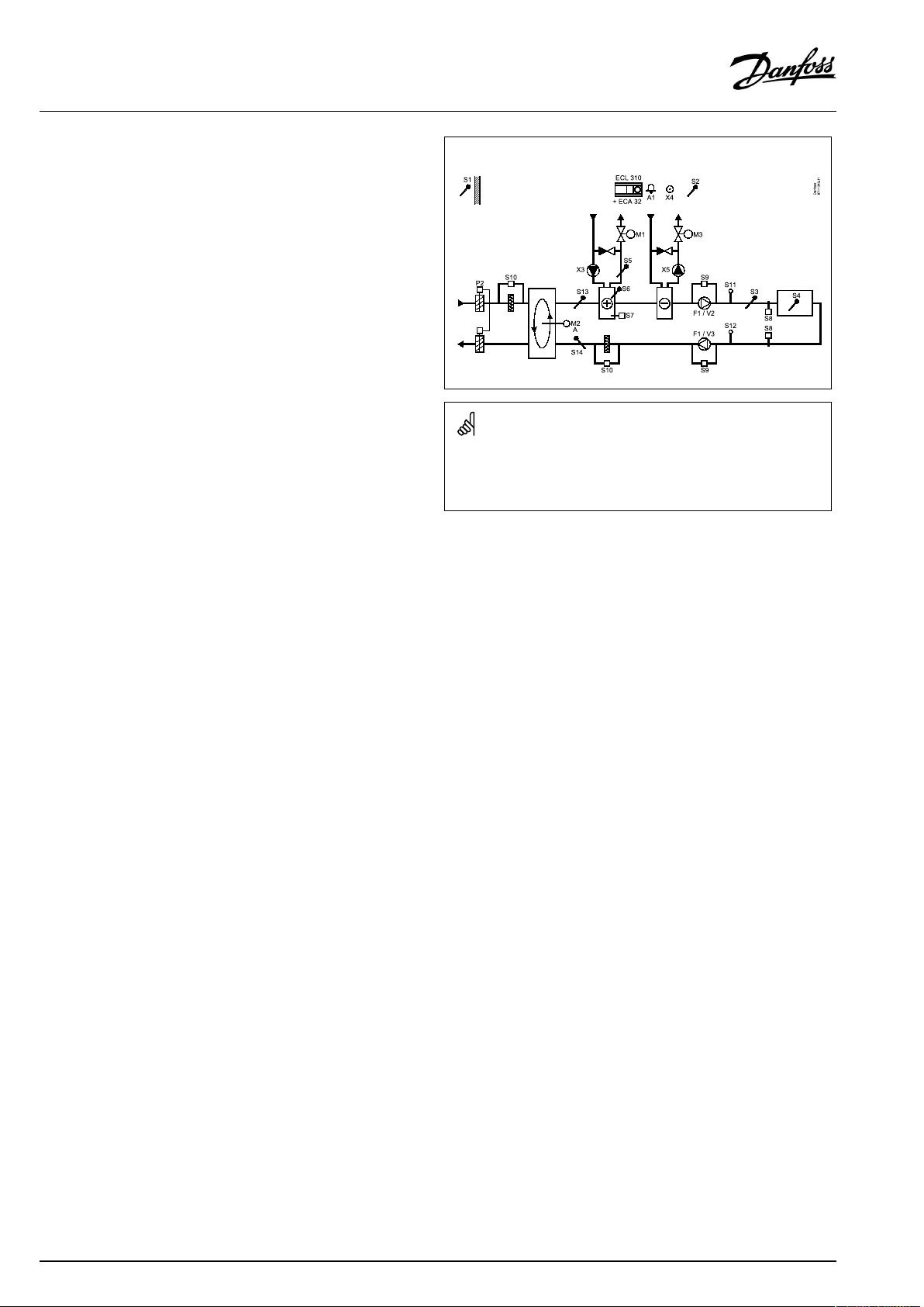
TypicalA314.6application:
Theshowndiagramisafundamentalandsimplifiedexampleanddoes
notcontainallcomponentsthatarenecessaryinasystem.
AllnamedcomponentsareconnectedtotheECLComfortcontroller.
Listofcomponents:
ECL310
ECA32
ElectroniccontrollerECLComfort310
Built-inextensionmodule
S1
Outdoortemperaturesensor
S2
(Optional)Compensationtemperaturesensor
S3Ducttemperaturesensor
S4
Roomtemperaturesensor*
S5
(Optional)Returntemperaturesensor
S6
(Optional)Frosttemperaturesensor
S7
(Optional)Frostthermostat
S8
(Optional)Firethermostat
Fanmonitor
S9
S10
Filtermonitor
S11
Inletpressuresensor
S12
Outletpressuresensor
S13
Entryducttemperaturesensor
S14
Exitducttemperaturesensor
F1
Fan(ON/OFF)
P2
Damper(ON/OFF)
X3
Circulationpump,heating(ON/OFF)
X4
Schedule3
X5
Circulationpump,cooling(ON/OFF)
P7
Recoverycircuitpump,ON/OFF ,(notillustrated)
M1
Motorizedcontrolvalve,heating(3-pointcontrolled)
M2
Rotatingheat-exchanger(0-10voltcontrolled)
M3
Motorizedcontrolvalve,cooling(3-pointcontrolled)
V2
Fanspeed(0-10voltcontrolled)
V3
Fanspeed(0-10voltcontrolled)
A1
Alarm
*Alternative:ECA30
18|©Danfoss|2021.06
AQ146286475947en-010601
Page 19

OperatingGuideECLComfort210/296/310,applicationA214/A314
Heating/coolingwithroomtemperatureandairpressure
control(continued)
M1andM3are3-pointcontrolled,whereasM2is0-10Vcontrolled.
Foradescriptionofalarms,compensationtemperature,return
temperaturelimitation(S5)andfrostprotection(S6andS7),please
readthesection‘A214andA314ingeneral’ .
AQ146286475947en-010601
©Danfoss|2021.06|19
Page 20
OperatingGuideECLComfort210/296/310,applicationA214/A314
TheadvancedheatingapplicationA314.7isveryflexible.These
arethebasicprinciples:
Heating/coolingwithroomtemperatureandairquality
control
Typically,theheatingtemperatureisadjustedaccordingtoyour
requirements.TheairducttemperaturesensorS3isthemost
importantsensor.ThedesiredtemperatureatS3issetintheECL
Comfortcontrollerasthe'Desiredinlettemperature' .
Therecoverycircuit,controlledbyM2,isconsideredasthemain
circuit,whereastheheatingcircuit(controlledbyM1)andthe
coolingcircuit(controlledbyM3)arethesupplementarycircuits.
ThemotorizedcontrolvalveM1(controllingtheheating
temperature)isopenedgraduallywhentheS3temperatureis
lowerthanthedesiredS3temperatureandviceversa.
Atcooling,themotorizedcontrolvalveM3controlsthecooling
temperature.
Roomtemperature:
Iftheroomtemperature(S4orECA30)doesnotequalthedesired
roomtemperature,thedesiredtemperatureatS3canbeadjusted.
AtoolowtemperatureatS4willactivatetheheatingcircuit(M1),
whereasatoohighairducttemperaturewillactivatethecooling
circuit(M3).A"Deadzone"(=numberofdegrees)canbeset
inordertoavoidunstableshiftsbetweenheatingandcooling
operation.
Bymeansofaweekschedule(upto3‘Comfort’periods/day),the
heatingcircuitcanbein‘Comfort’or‘Saving’mode(twodifferent
temperaturevaluesfordesiredinlettemperatureandtwodifferent
temperaturevaluesfordesiredroomtemperature).
ThefanF1isON/OFFcontrolledaccordingtotheschedule
andheatingdemand.AdamperP2canbeON/OFFcontrolled
accordingtoschedule.ThecirculationpumpX3isON/OFF
controlledaccordingtoheatingdemand.
Airqualitycontrol(CO2measuredin"ppm"):
ThefansV2andV3areincreasedinspeedwhentheppmvalue(010voltsignalmeasuredbyS11)exceedsaselectablelimit.Speed
relationbetweenV2andV3canbeset.Asanalternative,theS11
signalcanexpressanRHsignal(RelativeHumidity).
Heatrecovery:
Inordertoutilizeheatfromtheexitairduct,arotating
heat-exchanger,acrossheat-exchangerorafluidbatterycan
becontrolledbyM2.BasedontheoutdoortemperatureS1,the
entryducttemperatureS13andtheexitducttemperatureS14the
recoveryefficiency(in%)canbeindicated.
Nightcooling:
DuringSavingmodeapassivecoolingcanbearranged,mainly
underthefollowingconditions:
•roomtemperatureishigherthandesiredsavingroom
temperature
•outdoortemperatureislowerthantheroomtemperature
•schedule3isinComfortmode
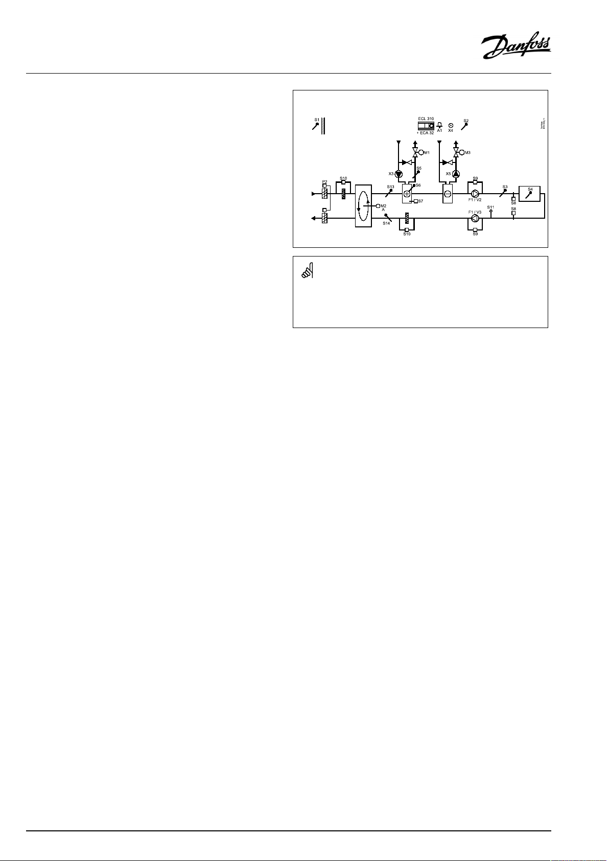
TypicalA314.7application:
Theshowndiagramisafundamentalandsimplifiedexampleanddoes
notcontainallcomponentsthatarenecessaryinasystem.
AllnamedcomponentsareconnectedtotheECLComfortcontroller.
Listofcomponents:
ECL310
ECA32
ElectroniccontrollerECLComfort310
Built-inextensionmodule
S1
Outdoortemperaturesensor
S2
(Optional)Compensationtemperaturesensor
S3Ducttemperaturesensor
S4
Roomtemperaturesensor*
S5
(Optional)Returntemperaturesensor
S6
(Optional)Frosttemperaturesensor
S7
(Optional)Frostthermostat
S8
(Optional)Firethermostat
Fanmonitor
S9
S10
Filtermonitor
S11
Airquality(CO2)signal(ppm).Alternative:Relative
Humiditysignal
S13
Entryducttemperaturesensor
S14
Exitducttemperaturesensor
F1
Fan(ON/OFF)
P2
Damper(ON/OFF)
X3
Circulationpump,heating(ON/OFF)
X4
Schedule3
X5
Circulationpump,cooling(ON/OFF)
P7
RecoverycircuitpumpON/OFF ,(notillustrated)
M1
Motorizedcontrolvalve,heating(3-pointcontrolled)
M2
Rotatingheat-exchanger(0-10voltcontrolled)
M3
Motorizedcontrolvalve,cooling(3-pointcontrolled)
V2
Fanspeed(0-10voltcontrolled)
V3
Fanspeed(0-10voltcontrolled)
A1
Alarm
*Alternative:ECA30
20|©Danfoss|2021.06
AQ146286475947en-010601
Page 21

OperatingGuideECLComfort210/296/310,applicationA214/A314
Heating/coolingwithroomtemperatureandairquality
control(continued)
M1andM3are3-pointcontrolled,whereasM2is0-10Vcontrolled.
Foradescriptionofalarms,compensationtemperature,return
temperaturelimitation(S5)andfrostprotection(S6andS7),please
readthesection‘A214andA314ingeneral’ .
AQ146286475947en-010601
©Danfoss|2021.06|21
Page 22

OperatingGuideECLComfort210/296/310,applicationA214/A314
TheadvancedheatingapplicationA314.9isveryflexible.These
arethebasicprinciples:
Heatingwithroomtemperatureandairqualitycontrol
Typically,theheatingtemperatureisadjustedaccordingtoyour
requirements.TheairducttemperaturesensorS3isthemost
importantsensor.ThedesiredtemperatureatS3issetintheECL
Comfortcontrollerasthe'Desiredinlettemperature' .
Theairmixingcircuit,controlledbyM2,isconsideredasthe
maincircuit,whereastheheatingcircuit,controlledbyM1,isthe
supplementarycircuit.
ThemotorizedcontrolvalveM1(controllingtheheating
temperature)isopenedgraduallywhentheS3temperatureis
lowerthanthedesiredS3temperatureandviceversa.
Roomtemperature:
Iftheroomtemperature(S4orECA30)doesnotequalthedesired
roomtemperature,thedesiredtemperatureatS3canbeadjusted.
Bymeansofaweekschedule(upto3‘Comfort’periods/day),the
heatingcircuitcanbein‘Comfort’or‘Saving’mode(twodifferent
temperaturevaluesfordesiredinlettemperatureandtwodifferent
temperaturevaluesfordesiredroomtemperature).
ThefanF1isON/OFFcontrolledaccordingtotheschedule
andheatingdemand.AdamperP2canbeON/OFFcontrolled
accordingtoschedule.ThecirculationpumpX3isON/OFF
controlledaccordingtoheatingdemand.
Airqualitycontrol(CO2measuredin"ppm"):
Whentheppmvalue(0-10voltsignalmeasuredbyS11)exceedsa
selectablelimit,thedamperM2graduallyopensinordertosupply
morefreshair.
WhenM2isfullyopen,thefansV2andV3aregraduallyincreased
inspeeduntiltheppmvalueisacceptable.Speedrelationbetween
V2andV3canbeset.
Asanalternative,theS11signalcanexpressanRHsignal(Relative
Humidity).
Ventilationduringsavingperiod:
Adesiredfanspeedcanbeset.
•Roomtemperaturesignalmustbepresent
•ThenightdamperP8willopen
•ThefanV2willoperateatreducedspeed
•ThefanV3isOFF
•P2isOFF
•M2isOFF
M1is3-pointcontrolled,whereasM2is0-10Vcontrolled.
Foradescriptionofalarms,compensationtemperature,return
temperaturelimitation(S5)andfrostprotection(S6andS7),please
readthesection‘A214andA314ingeneral’ .
TypicalA314.9application:
Theshowndiagramisafundamentalandsimplifiedexampleanddoes
notcontainallcomponentsthatarenecessaryinasystem.
AllnamedcomponentsareconnectedtotheECLComfortcontroller.
Listofcomponents:
ECL310
ECA32
ElectroniccontrollerECLComfort310
Built-inextensionmodule
S1
Outdoortemperaturesensor
S2
(Optional)Compensationtemperaturesensor
S3Ducttemperaturesensor
S4
Roomtemperaturesensor*
S5
(Optional)Returntemperaturesensor
S6
(Optional)Frosttemperaturesensor
S7
(Optional)Frostthermostat
S8
(Optional)Firethermostat
Fanmonitor
S9
S10
Filtermonitor
S11
Airquality(CO2)signal(ppm).Alternative:Relative
Humiditysignal
F1
Fan(ON/OFF)
P2
Damper(ON/OFF),notillustrated
X3
Circulationpump,heating(ON/OFF)
X4
Schedule3
P8
Nightdamper,notillustrated
M1
Motorizedcontrolvalve,heating(3-pointcontrolled)
M2
Motorizeddamper(0-10voltcontrolled)
V2
Fanspeed(0-10voltcontrolled)
V3
Fanspeed(0-10voltcontrolled)
A1
Alarm
*Alternative:ECA30
22|©Danfoss|2021.06
AQ146286475947en-010601
Page 23

OperatingGuideECLComfort210/296/310,applicationA214/A314
A214andA314ingeneral:
Compensationtemperature(optional):
Ifthemeasuredcompensationtemperature(S1orS2)ishigheror
lowerthanthelimitationvalue,thedesiredtemperatureatS3can
beadjusted.Thecompensationtemperaturecanbemeasured
bytheoutdoortemperaturesensororforexampleanadditional
roomtemperaturesensor.
Overridepossibilities:
Unusedinputcan,bymeansofanoverrideswitch,beusedto
overridethescheduletoafixed'Comfort'or'Saving'mode.
Alarmfunctions:
Thealarm(relay4inECL210,relay6inECL310)isactivated:
1.IfanunaccepteddeviationbetweenthedesiredandactualS3
temperatureoccurs.
2.Ifafrostthermostat(S7)isactivated.
3.IfafrosttemperatureisdetectedatS5orS6.
4.Ifthefirealarm(S8)isactivated.
5.Ifatemperaturesensororitsconnectiondisconnects/short
circuits.
A214.2,A214.3,A214.4,A214.5,A314.1,A314.2andA314.3:
Returntemperature(optional):
Ifthemeasuredreturntemperature(S5)doesnotequalthe
limitationvalue(typically,thereturntemperaturebecomeshigher
thanthelimitationvalue),thedesiredtemperatureatS3canbe
adjusted(typicallytoalowervalue).Thisresultsinagradualclosing
ofthemotorizedcontrolvalve.
Frostprotection(optional):
TemperaturesensorS6and/orfrostthermostatS7canprotect
theheatexchangeragainstfrost.
Furthermore,iftheS5temperaturebecomestoolow,italsocan
enablethefrostprotection.
Anactivatedfrostprotectionwillstartthealarm,stopthefanF1,
closethedamperP2andfullyopenthemotorizedcontrolvalveM1.
Firealarm(optional):
Anactivatedfirealarminputwillstartthealarm,stopthefanF1,
closethedamperP2andclosethemotorizedcontrolvalves.
AQ146286475947en-010601
©Danfoss|2021.06|23
Page 24

OperatingGuideECLComfort210/296/310,applicationA214/A314
A314.4,A314.5,A314.6andA314.7:
Efficiencycalculation:
x
(Entryduct-Outdoor)
(Exitduct-Outdoor)
Example:
Outdoor(S1)
Entryduct(S13)
Exitduct(S14)
(16-7)
(24-7)
A314.4,A314.5,A314.6andA314.7:
=
=
=
x
100
7
16
24
=
100
=
%
°C
°C
°C
53%
Circuit1'soverviewdisplayshowsoutputstatusforM1.
Anapproximate%-valueforM1'spositionisalsoindicatedinorder
tofollowthecontrolprocedure.
Thecontrollerispre-programmedwithfactorysettingsthatareshown
inthe‘ParameterIDoverview’appendix.
24|©Danfoss|2021.06
AQ146286475947en-010601
Page 25
OperatingGuideECLComfort210/296/310,applicationA214/A314
2.2Identifyingthesystemtype
Sketchyourapplication
TheECLComfortcontrollerseriesisdesignedforawiderange
ofheating,domestichot-water(DHW)andcoolingsystemswith
differentconfigurationsandcapacities.Ifyoursystemdiffers
fromthediagramsshownhere,youmaywanttomakeasketch
ofthesystemabouttobeinstalled.Thismakesiteasiertouse
theOperatingGuide,whichwillguideyoustep-by-stepfrom
installationtofinaladjustmentsbeforetheend-usertakesover.
TheECLComfortcontrollerisauniversalcontrollerthatcanbe
usedforvarioussystems.Basedontheshownstandardsystems,
itispossibletoconfigureadditionalsystems.Inthischapteryou
findthemostfrequentlyusedsystems.Ifyoursystemisnotquite
asshownbelow,findthediagramwhichhasthebestresemblance
withyoursystemandmakeyourowncombinations.
Thecirculationpump(s)inheatingcircuit(s)canbeplacedintheflow
aswellasthereturn.Placethepumpaccordingtothemanufacturer’s
specification.
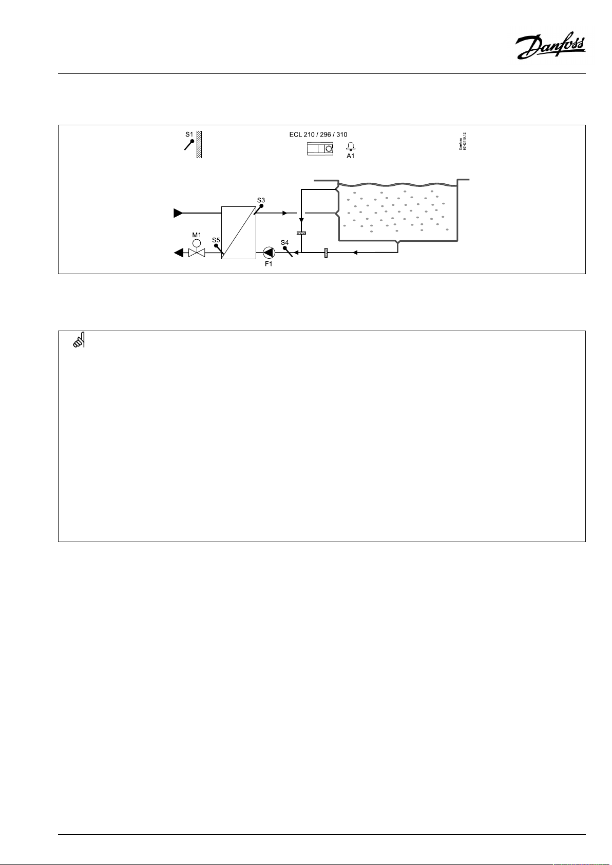
A214.1examplea
Ventilationsystemwithcoolingandconstantroomtemperaturecontrol
Settingadvice:
Setdesiredroomtemperature,forexample20°C.
Setdesiredbalancetemperature,forexample12°C.
Ifaroomtemperaturesensorisnotconnected,thedesiredducttemperatureatS3willcorrespondtothedesiredroomtemperature.
AQ146286475947en-010601
©Danfoss|2021.06|25
Page 26
OperatingGuideECLComfort210/296/310,applicationA214/A314
A214.1exampleb
Ventilationsystemwithcoolingandconstantroomtemperaturecontrol.Chillerhasconstantflow.
Settingadvice:
Setdesiredroomtemperature,forexample20°C.
Setdesiredbalancetemperature,forexample12°C.
Ifaroomtemperaturesensorisnotconnected,thedesiredducttemperatureatS3willcorrespondtothedesiredroomtemperature.
A214.1examplec
Ventilationsystem(fancoils)withcoolingandconstantroomtemperaturecontrol
Settingadvice:
Setdesiredroomtemperature,forexample5°C.
Setdesiredbalancetemperature,forexample1°C.
Ifaroomtemperaturesensorisnotconnected,thedesiredflowtemperatureatS3willcorrespondtothedesiredroomtemperature.
26|©Danfoss|2021.06
AQ146286475947en-010601
Page 27
OperatingGuideECLComfort210/296/310,applicationA214/A314
A214.1exampled
Coolingsystemwithconstantflowtemperaturecontrol
Settingadvice:
Setdesiredroomtemperature,forexample1°C.
Ifaroomtemperaturesensorisnotconnected,thedesiredflowtemperatureatS3willcorrespondtothedesiredroomtemperature.
Set‘Fancut-indelay’(IDno.11086—‘Settings’ ,‘Fan/acc.control’)to0seconds.
A214.1examplee
Coolingsysteminceilingandconstantroomtemperaturecontrolinforexampleawinecellar
Settingadvice:
Setdesiredroomtemperature,forexample14°C.
Setdesiredbalancetemperature,forexample10°C.
Ifaroomtemperaturesensorisnotconnected,thedesiredflowtemperatureatS3willcorrespondtothedesiredroomtemperature.
Set‘Fancut-indelay’(IDno.11086—‘Settings’ ,‘Fan/acc.control’)to0seconds.
AQ146286475947en-010601
©Danfoss|2021.06|27
Page 28
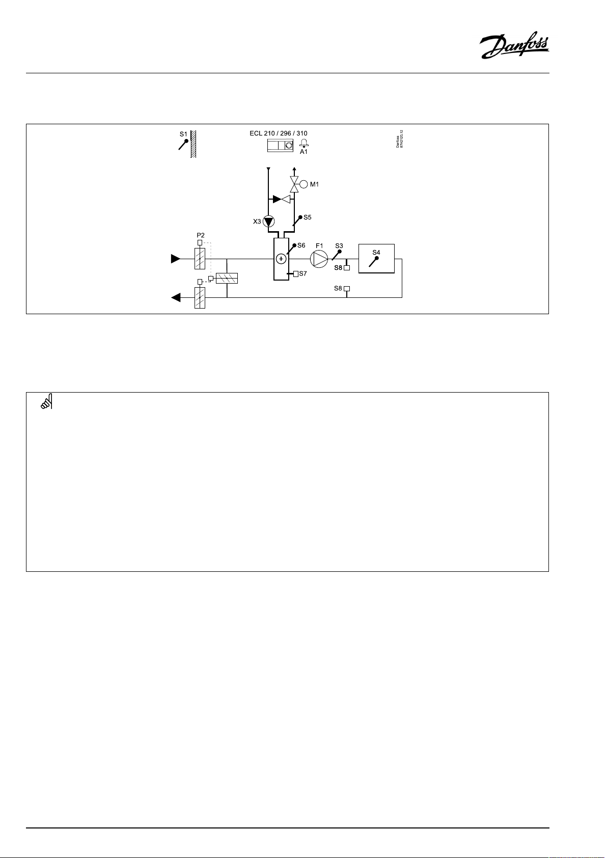
OperatingGuideECLComfort210/296/310,applicationA214/A314
A214.2examplea
Ventilationsystemwithheatingandconstantducttemperaturecontrol
Sensoradvice:
SensorS3andS4mustbeconnected.Ifnot,thefan(F1)stops,thedamper(P2)andmotorizedcontrolvalve(M1)close.
Navigation:
Specialsettingsforsensors/thermostatsusedasfrostprotection:
S6*frosttemperaturesensor—MENU\Alarm\FrostT\Alarmvalue
S5returntemperaturesensor—MENU\Alarm\LimitTfrost\Alarmvalue
ClosingcontactoftheS7*frostthermostat—MENU\Alarm\Frostthermostat\Alarmvalue
OpeningcontactoftheS7*frostthermostat—MENU\Alarm\Frostthermostat\Alarmvalue
*bothfrostprotectionmethods,bymeansofS6and/orS7,canbeused
Specialsettingsforthermostatsusedasfirealarm:
ClosingcontactoftheS8firethermostat—MENU\Alarm\Firesafety\Alarmvalue
OpeningcontactoftheS8firethermostat—MENU\Alarm\Firesafety\Alarmvalue
IDno.:
11676
11656
116160
11616
116360
11636
Recommended
setting:
5°C
5°C
1
1
28|©Danfoss|2021.06
AQ146286475947en-010601
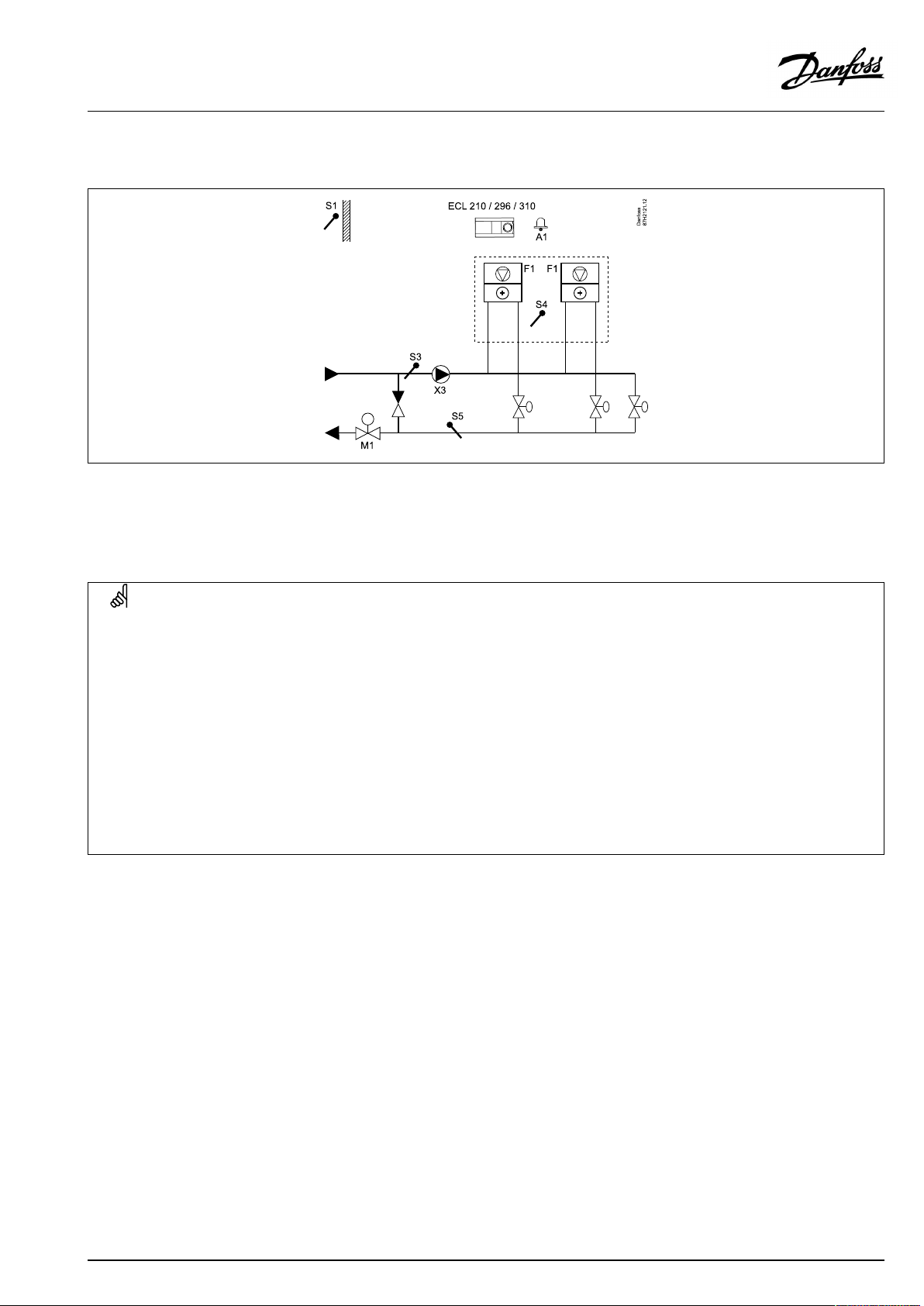
Page 29
OperatingGuideECLComfort210/296/310,applicationA214/A314
A214.2exampleb
Heatingofaswimmingpool,constantwatertemperaturecontrol
Sensoradvice:
SensorS3andS4mustbeconnected.Ifnot,thepump(F1)stopsandmotorizedcontrolvalve(M1)closes.
Navigation:
Specialsettingsforsensors/thermostatsusedasfrostprotection:
S6*frosttemperaturesensor—MENU\Alarm\FrostT\Alarmvalue
S5returntemperaturesensor—MENU\Alarm\LimitTfrost\Alarmvalue
ClosingcontactoftheS7*frostthermostat—MENU\Alarm\Frostthermostat\Alarmvalue
OpeningcontactoftheS7*frostthermostat—MENU\Alarm\Frostthermostat\Alarmvalue
*bothfrostprotectionmethods,bymeansofS6and/orS7,canbeused
Specialsettingsforthermostatsusedasfirealarm:
ClosingcontactoftheS8firethermostat—MENU\Alarm\Firesafety\Alarmvalue
OpeningcontactoftheS8firethermostat—MENU\Alarm\Firesafety\Alarmvalue
Othersettings:
Fancut-indelay—MENU\Settings\Fan/acc.control
IDno.:
11676
11656
116160
11616
116360
11636
110860
Recommended
setting:
5°C
5°C
1
1
AQ146286475947en-010601
©Danfoss|2021.06|29
Page 30
OperatingGuideECLComfort210/296/310,applicationA214/A314
A214.3examplea
Ventilationsystemwithheatingandconstantroomtemperaturecontrol
Settingadvice:
Setdesiredroomtemperature,forexample20°C.
Setdesiredbalancetemperature,forexample20°C.
Ifaroomtemperaturesensorisnotconnected,thedesiredducttemperatureatS3willcorrespondtothedesiredroomtemperature.
Navigation:
Specialsettingsforsensors/thermostatsusedasfrostprotection:
S6*frosttemperaturesensor—MENU\Alarm\FrostT\Alarmvalue
S5returntemperaturesensor—MENU\Alarm\LimitTfrost\Alarmvalue
ClosingcontactoftheS7*frostthermostat—MENU\Alarm\Frostthermostat\Alarmvalue
OpeningcontactoftheS7*frostthermostat—MENU\Alarm\Frostthermostat\Alarmvalue
*bothfrostprotectionmethods,bymeansofS6and/orS7,canbeused
Specialsettingsforthermostatsusedasfirealarm:
ClosingcontactoftheS8firethermostat—MENU\Alarm\Firesafety\Alarmvalue
OpeningcontactoftheS8firethermostat—MENU\Alarm\Firesafety\Alarmvalue
IDno.:
11676
11656
116160
11616
116360
11636
Recommended
setting:
5°C
5°C
1
1
30|©Danfoss|2021.06
AQ146286475947en-010601
Page 31
OperatingGuideECLComfort210/296/310,applicationA214/A314
A214.3exampleb
Ventilationsystem(fancoils)withheatingandconstantroomtemperaturecontrol
Settingadvice:
Setdesiredroomtemperature,forexample20°C.
Setdesiredbalancetemperature,forexample35°C.
Ifaroomtemperaturesensorisnotconnected,thedesiredflowtemperatureatS3willcorrespondtothedesiredroomtemperature.
Navigation:
Specialsettingsforsensors/thermostatsusedasfrostprotection:
S6*frosttemperaturesensor—MENU\Alarm\FrostT\Alarmvalue
S5returntemperaturesensor—MENU\Alarm\LimitTfrost\Alarmvalue
ClosingcontactoftheS7*frostthermostat—MENU\Alarm\Frostthermostat\Alarmvalue
OpeningcontactoftheS7*frostthermostat—MENU\Alarm\Frostthermostat\Alarmvalue
*bothfrostprotectionmethods,bymeansofS6and/orS7,canbeused
Specialsettingsforthermostatsusedasfirealarm:
ClosingcontactoftheS8firethermostat—MENU\Alarm\Firesafety\Alarmvalue
OpeningcontactoftheS8firethermostat—MENU\Alarm\Firesafety\Alarmvalue
IDno.:
11676
11656
116160
11616
116360
11636
Recommended
setting:
5°C
5°C
1
1
AQ146286475947en-010601
©Danfoss|2021.06|31
Page 32

OperatingGuideECLComfort210/296/310,applicationA214/A314
A214.4examplea
Ventilationsystemwithheating,coolingandconstantducttemperaturecontrol
Sensoradvice:
SensorS3andS4mustbeconnected.Ifnot,thefan(F1)stops,thedamper(P2)andmotorizedcontrolvalves(M1/M2)close.
Navigation:
Specialsettingsforsensors/thermostatsusedasfrostprotection:
S6*frosttemperaturesensor—MENU\Alarm\FrostT\Alarmvalue
S5returntemperaturesensor—MENU\Alarm\LimitTfrost\Alarmvalue
ClosingcontactoftheS7*frostthermostat—MENU\Alarm\Frostthermostat\Alarmvalue
OpeningcontactoftheS7*frostthermostat—MENU\Alarm\Frostthermostat\Alarmvalue
*bothfrostprotectionmethods,bymeansofS6and/orS7,canbeused
Specialsettingsforthermostatsusedasfirealarm:
ClosingcontactoftheS8firethermostat—MENU\Alarm\Firesafety\Alarmvalue
OpeningcontactoftheS8firethermostat—MENU\Alarm\Firesafety\Alarmvalue
IDno.:
11676
11656
116160
11616
116360
11636
Recommended
setting:
5°C
5°C
1
1
32|©Danfoss|2021.06
AQ146286475947en-010601
Page 33

OperatingGuideECLComfort210/296/310,applicationA214/A314
A214.4exampleb
Ventilationsystemwithheating,passivecooling(outsideair)andconstantducttemperaturecontrol
Sensoradvice:
SensorS3andS4mustbeconnected.Ifnot,thefan(F1)stops,thedamper(P2)andmotorizedcontrolvalves(M1/M2)close.
Navigation:
Specialsettingsforsensors/thermostatsusedasfrostprotection:
S6*frosttemperaturesensor—MENU\Alarm\FrostT\Alarmvalue
S5returntemperaturesensor—MENU\Alarm\LimitTfrost\Alarmvalue
ClosingcontactoftheS7*frostthermostat—MENU\Alarm\Frostthermostat\Alarmvalue
OpeningcontactoftheS7*frostthermostat—MENU\Alarm\Frostthermostat\Alarmvalue
*bothfrostprotectionmethods,bymeansofS6and/orS7,canbeused
Specialsettingsforthermostatsusedasfirealarm:
ClosingcontactoftheS8firethermostat—MENU\Alarm\Firesafety\Alarmvalue
OpeningcontactoftheS8firethermostat—MENU\Alarm\Firesafety\Alarmvalue
IDno.:
11676
11656
116160
11616
116360
11636
Recommended
setting:
5°C
5°C
1
1
AQ146286475947en-010601
©Danfoss|2021.06|33
Page 34

OperatingGuideECLComfort210/296/310,applicationA214/A314
A214.5examplea
Ventilationsystemwithheating,coolingandconstantroomtemperaturecontrol
Settingadvice:
Setdesiredroomtemperature,forexample20°C.
Setdesiredbalancetemperature,forexample20°C.
Ifaroomtemperaturesensorisnotconnected,thedesiredducttemperatureatS3willcorrespondtothedesiredroomtemperature.
Navigation:
Specialsettingsforsensors/thermostatsusedasfrostprotection:
S6*frosttemperaturesensor—MENU\Alarm\FrostT\Alarmvalue
S5returntemperaturesensor—MENU\Alarm\LimitTfrost\Alarmvalue
ClosingcontactoftheS7*frostthermostat—MENU\Alarm\Frostthermostat\Alarmvalue
OpeningcontactoftheS7*frostthermostat—MENU\Alarm\Frostthermostat\Alarmvalue
*bothfrostprotectionmethods,bymeansofS6and/orS7,canbeused
Specialsettingsforthermostatsusedasfirealarm:
ClosingcontactoftheS8firethermostat—MENU\Alarm\Firesafety\Alarmvalue
OpeningcontactoftheS8firethermostat—MENU\Alarm\Firesafety\Alarmvalue
IDno.:
11676
11656
116160
11616
116360
11636
Recommended
setting:
5°C
5°C
1
1
34|©Danfoss|2021.06
AQ146286475947en-010601
Page 35

OperatingGuideECLComfort210/296/310,applicationA214/A314
A214.5exampleb
Ventilationsystemwithheating,passivecooling(outsideair)andconstantroomtemperaturecontrol
Settingadvice:
Setdesiredroomtemperature,forexample20°C.
Setdesiredbalancetemperature,forexample20°C.
Ifaroomtemperaturesensorisnotconnected,thedesiredducttemperatureatS3willcorrespondtothedesiredroomtemperature.
Navigation:
Specialsettingsforsensors/thermostatsusedasfrostprotection:
S6*frosttemperaturesensor—MENU\Alarm\FrostT\Alarmvalue
S5returntemperaturesensor—MENU\Alarm\LimitTfrost\Alarmvalue
ClosingcontactoftheS7*frostthermostat—MENU\Alarm\Frostthermostat\Alarmvalue
OpeningcontactoftheS7*frostthermostat—MENU\Alarm\Frostthermostat\Alarmvalue
*bothfrostprotectionmethods,bymeansofS6and/orS7,canbeused
Specialsettingsforthermostatsusedasfirealarm:
ClosingcontactoftheS8firethermostat—MENU\Alarm\Firesafety\Alarmvalue
OpeningcontactoftheS8firethermostat—MENU\Alarm\Firesafety\Alarmvalue
IDno.:
11676
11656
116160
11616
116360
11636
Recommended
setting:
5°C
5°C
1
1
AQ146286475947en-010601
©Danfoss|2021.06|35
Page 36

OperatingGuideECLComfort210/296/310,applicationA214/A314
A214.5examplec
Ventilationsystemwithheating,cross-flowheatexchangercontrolandconstantroomtemperaturecontrol
Settingadvice:
Setdesiredroomtemperature,forexample20°C.
Setdesiredbalancetemperature,forexample20°C.
Ifaroomtemperaturesensorisnotconnected,thedesiredducttemperatureatS3willcorrespondtothedesiredroomtemperature.
Navigation:
Specialsettingsforsensors/thermostatsusedasfrostprotection:
S6*frosttemperaturesensor—MENU\Alarm\FrostT\Alarmvalue
S5returntemperaturesensor—MENU\Alarm\LimitTfrost\Alarmvalue
ClosingcontactoftheS7*frostthermostat—MENU\Alarm\Frostthermostat\Alarmvalue
OpeningcontactoftheS7*frostthermostat—MENU\Alarm\Frostthermostat\Alarmvalue
*bothfrostprotectionmethods,bymeansofS6and/orS7,canbeused
Specialsettingsforthermostatsusedasfirealarm:
ClosingcontactoftheS8firethermostat—MENU\Alarm\Firesafety\Alarmvalue
OpeningcontactoftheS8firethermostat—MENU\Alarm\Firesafety\Alarmvalue
IDno.:
11676
11656
116160
11616
116360
11636
Recommended
setting:
5°C
5°C
1
1
36|©Danfoss|2021.06
AQ146286475947en-010601
Page 37

OperatingGuideECLComfort210/296/310,applicationA214/A314
A214.6examplea
Heatingsystemwith3–portmixingvalve
A214.6exampleb
Heatingsystemwithheatexchanger
Settingadvice:
SensorS3mustbeconnected.Ifnot,thepump(F1)stopsandmotorizedcontrolvalve(M1)closes.
AQ146286475947en-010601
©Danfoss|2021.06|37
Page 38
OperatingGuideECLComfort210/296/310,applicationA214/A314
A314.1examplea
Ventilationsystemwithheating,passivecooling(outsideair)andconstantducttemperaturecontrol.Analogcontrolledpassive
cooling(M2).
Sensoradvice:
SensorS3andS4mustbeconnected.Ifnot,thefan(F1)stops,thedamper(P2)andmotorizedcontrolvalves(M1/M2)close.
Navigation:
Specialsettingsforsensors/thermostatsusedasfrostprotection:
S6*frosttemperaturesensor—MENU\Alarm\FrostT\Alarmvalue
S5returntemperaturesensor—MENU\Alarm\LimitTfrost\Alarmvalue
ClosingcontactoftheS7*frostthermostat—MENU\Alarm\Frostthermostat\Alarmvalue
OpeningcontactoftheS7*frostthermostat—MENU\Alarm\Frostthermostat\Alarmvalue
*bothfrostprotectionmethods,bymeansofS6and/orS7,canbeused
Specialsettingsforthermostatsusedasfirealarm:
ClosingcontactoftheS8firethermostat—MENU\Alarm\Firesafety\Alarmvalue
OpeningcontactoftheS8firethermostat—MENU\Alarm\Firesafety\Alarmvalue
IDno.:
11676
11656
116160
11616
116360
11636
Recommended
setting:
5°C
5°C
1
1
38|©Danfoss|2021.06
AQ146286475947en-010601
Page 39

OperatingGuideECLComfort210/296/310,applicationA214/A314
A314.1exampleb
Ventilationsystemwithheating,coolingandconstantducttemperaturecontrol.Analogcontrolledcooling(M2).
Sensoradvice:
SensorS3andS4mustbeconnected.Ifnot,thefan(F1)stops,thedamper(P2)andmotorizedcontrolvalves(M1/M2)close.
Navigation:
Specialsettingsforsensors/thermostatsusedasfrostprotection:
S6*frosttemperaturesensor—MENU\Alarm\FrostT\Alarmvalue
S5returntemperaturesensor—MENU\Alarm\LimitTfrost\Alarmvalue
ClosingcontactoftheS7*frostthermostat—MENU\Alarm\Frostthermostat\Alarmvalue
OpeningcontactoftheS7*frostthermostat—MENU\Alarm\Frostthermostat\Alarmvalue
*bothfrostprotectionmethods,bymeansofS6and/orS7,canbeused
Specialsettingsforthermostatsusedasfirealarm:
ClosingcontactoftheS8firethermostat—MENU\Alarm\Firesafety\Alarmvalue
OpeningcontactoftheS8firethermostat—MENU\Alarm\Firesafety\Alarmvalue
IDno.:
11676
11656
116160
11616
116360
11636
Recommended
setting:
5°C
5°C
1
1
AQ146286475947en-010601
©Danfoss|2021.06|39
Page 40

OperatingGuideECLComfort210/296/310,applicationA214/A314
A314.2examplea
Ventilationsystemwithheating,passivecooling(outsideair)andconstantroomtemperaturecontrol.Analogcontrolledpassive
cooling(M2).
Settingadvice:
Setdesiredroomtemperature,forexample20°C.
Setdesiredbalancetemperature,forexample20°C.
Ifaroomtemperaturesensorisnotconnected,thedesiredducttemperatureatS3willcorrespondtothedesiredroomtemperature.
Navigation:
Specialsettingsforsensors/thermostatsusedasfrostprotection:
S6*frosttemperaturesensor—MENU\Alarm\FrostT\Alarmvalue
S5returntemperaturesensor—MENU\Alarm\LimitTfrost\Alarmvalue
ClosingcontactoftheS7*frostthermostat—MENU\Alarm\Frostthermostat\Alarmvalue
OpeningcontactoftheS7*frostthermostat—MENU\Alarm\Frostthermostat\Alarmvalue
*bothfrostprotectionmethods,bymeansofS6and/orS7,canbeused
Specialsettingsforthermostatsusedasfirealarm:
ClosingcontactoftheS8firethermostat—MENU\Alarm\Firesafety\Alarmvalue
OpeningcontactoftheS8firethermostat—MENU\Alarm\Firesafety\Alarmvalue
IDno.:
11676
11656
116160
11616
116360
11636
Recommended
setting:
5°C
5°C
1
1
40|©Danfoss|2021.06
AQ146286475947en-010601
Page 41

OperatingGuideECLComfort210/296/310,applicationA214/A314
A314.2exampleb
Ventilationsystemwithheating,coolingandconstantroomtemperaturecontrol.Analogcontrolledcooling(M2).
Settingadvice:
Setdesiredroomtemperature,forexample20°C.
Setdesiredbalancetemperature,forexample20°C.
Ifaroomtemperaturesensorisnotconnected,thedesiredducttemperatureatS3willcorrespondtothedesiredroomtemperature.
Navigation:
Specialsettingsforsensors/thermostatsusedasfrostprotection:
S6*frosttemperaturesensor—MENU\Alarm\FrostT\Alarmvalue
S5returntemperaturesensor—MENU\Alarm\LimitTfrost\Alarmvalue
ClosingcontactoftheS7*frostthermostat—MENU\Alarm\Frostthermostat\Alarmvalue
OpeningcontactoftheS7*frostthermostat—MENU\Alarm\Frostthermostat\Alarmvalue
*bothfrostprotectionmethods,bymeansofS6and/orS7,canbeused
Specialsettingsforthermostatsusedasfirealarm:
ClosingcontactoftheS8firethermostat—MENU\Alarm\Firesafety\Alarmvalue
OpeningcontactoftheS8firethermostat—MENU\Alarm\Firesafety\Alarmvalue
IDno.:
11676
11656
116160
11616
116360
11636
Recommended
setting:
5°C
5°C
1
1
AQ146286475947en-010601
©Danfoss|2021.06|41
Page 42

OperatingGuideECLComfort210/296/310,applicationA214/A314
A314.3examplea
Ventilationsystemwithheatingandconstantroomtemperaturecontrol.Analogcontrolledfanspeed(V1)basedonoutdoorwindspeed.
Settingadvice:
Setdesiredroomtemperature,forexample20°C.
Setdesiredbalancetemperature,forexample35°C.
Ifaroomtemperaturesensorisnotconnected,thedesiredducttemperatureatS3willcorrespondtothedesiredroomtemperature.
Navigation:
Specialsettingsforsensors/thermostatsusedasfrostprotection:
S6*frosttemperaturesensor—MENU\Alarm\FrostT\Alarmvalue
S5returntemperaturesensor—MENU\Alarm\LimitTfrost\Alarmvalue
ClosingcontactoftheS7*frostthermostat—MENU\Alarm\Frostthermostat\Alarmvalue
OpeningcontactoftheS7*frostthermostat—MENU\Alarm\Frostthermostat\Alarmvalue
*bothfrostprotectionmethods,bymeansofS6and/orS7,canbeused
Specialsettingsforthermostatsusedasfirealarm:
ClosingcontactoftheS8firethermostat—MENU\Alarm\Firesafety\Alarmvalue
OpeningcontactoftheS8firethermostat—MENU\Alarm\Firesafety\Alarmvalue
IDno.:
11676
11656
116160
11616
116360
11636
Recommended
setting:
5°C
5°C
1
1
42|©Danfoss|2021.06
AQ146286475947en-010601
Page 43

OperatingGuideECLComfort210/296/310,applicationA214/A314
A314.3exampleb
Ventilationsystemwithheatingandconstantroomtemperaturecontrol.Analogcontrolledaircurtain(V1)speedbasedonoutdoorwind
speed.
Settingadvice:
Setdesiredroomtemperature,forexample20°C.
Setdesiredbalancetemperature,forexample35°C.
Ifaroomtemperaturesensorisnotconnected,thedesiredducttemperatureatS3willcorrespondtothedesiredroomtemperature.
Navigation:
Specialsettingsforsensors/thermostatsusedasfrostprotection:
S6*frosttemperaturesensor—MENU\Alarm\FrostT\Alarmvalue
S5returntemperaturesensor—MENU\Alarm\LimitTfrost\Alarmvalue
ClosingcontactoftheS7*frostthermostat—MENU\Alarm\Frostthermostat\Alarmvalue
OpeningcontactoftheS7*frostthermostat—MENU\Alarm\Frostthermostat\Alarmvalue
*bothfrostprotectionmethods,bymeansofS6and/orS7,canbeused
Specialsettingsforthermostatsusedasfirealarm:
ClosingcontactoftheS8firethermostat—MENU\Alarm\Firesafety\Alarmvalue
OpeningcontactoftheS8firethermostat—MENU\Alarm\Firesafety\Alarmvalue
IDno.:
11676
11656
116160
11616
116360
11636
Recommended
setting:
5°C
5°C
1
1
AQ146286475947en-010601
©Danfoss|2021.06|43
Page 44

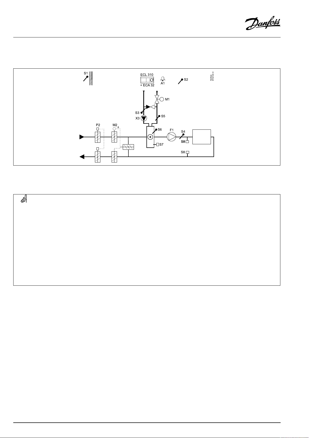
OperatingGuideECLComfort210/296/310,applicationA214/A314
A314.4examplea
Ventilationsystemwithheating,passivecooling(outsideair)androomtemperaturecontrol.Analogcontrolledspeedoffansinrelation
topressures.Analogcontrolledspeedofrotaryheatexchanger(M2)forheatrecovery.
A314.4exampleb
Ventilationsystemwithheating,passivecooling(outsideair)androomtemperaturecontrol.Analogcontrolledspeedoffansinrelationto
pressures.Analogcontrolleddamper(M2)forheatrecoverybymeansofacrossheatexchanger.
44|©Danfoss|2021.06
AQ146286475947en-010601
Page 45
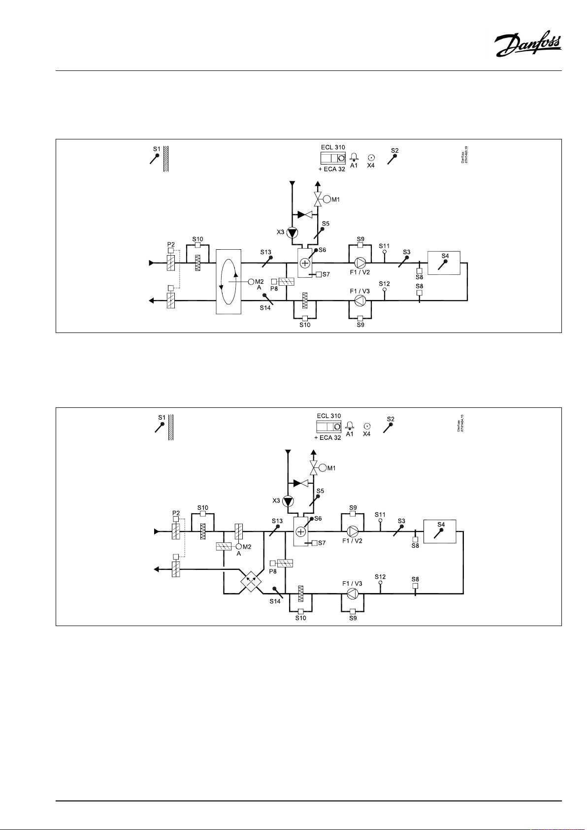
OperatingGuideECLComfort210/296/310,applicationA214/A314
A314.4examplec
Ventilationsystemwithheating,passivecooling(outsideair)androomtemperaturecontrol.Analogcontrolledspeedoffansinrelationto
pressures.Analogcontrolledspeedofrotaryheatexchanger(M2)forheatrecovery.ControlofNightdamperP8forreducedventilation
duringsavingperiods.
A314.4exampled
Ventilationsystemwithheating,passivecooling(outsideair)androomtemperaturecontrol.Analogcontrolledspeedoffansin
relationtopressures.Analogcontrolleddamper(M2)forheatrecoverybymeansofacrossheatexchanger.ControlofNightdamper
P8forreducedventilationduringsavingperiods.
AQ146286475947en-010601
©Danfoss|2021.06|45
Page 46
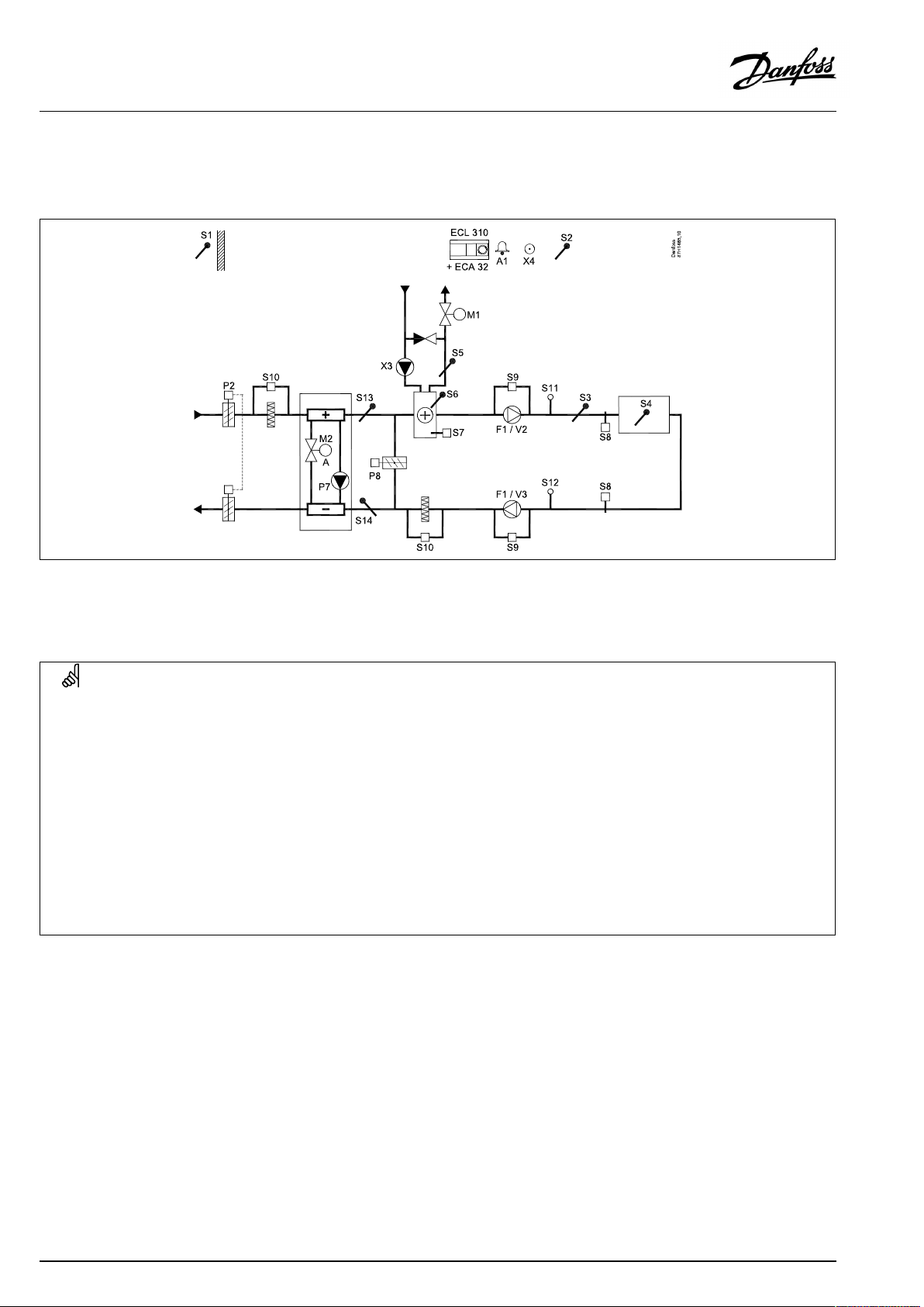
OperatingGuideECLComfort210/296/310,applicationA214/A314
A314.4examplee
Ventilationsystemwithheating,passivecooling(outsideair)androomtemperaturecontrol.Analogcontrolledspeedoffansinrelation
topressures.Analogcontrolledvalve(M2)forheatrecoverybymeansofaFluidbattery.ControlofNightdamperP8forreduced
ventilationduringsavingperiods.
Sensoradvice:
SensorS3mustbeconnected.Ifnot,thefanF1stopsandmotorizedcontrolvalveM1closes.
S1,S13andS14mustbeconnectedinordertocalculatetherecoveryefficiency.
Navigation:
Specialsettingsforsensors/thermostatsusedasfrostprotection:
S6*frosttemperaturesensor—MENU\Alarm\FrostT\Alarmvalue
S5returntemperaturesensor—MENU\Alarm\LimitTfrost\Alarmvalue
ClosingcontactoftheS7*frostthermostat—MENU\Alarm\Frostthermostat\Alarmvalue
OpeningcontactoftheS7*frostthermostat—MENU\Alarm\Frostthermostat\Alarmvalue
*bothfrostprotectionmethods,bymeansofS6and/orS7,canbeused
Specialsettingsforthermostatsusedasfirealarm:
ClosingcontactoftheS8firethermostat—MENU\Alarm\Firesafety\Alarmvalue
OpeningcontactoftheS8firethermostat—MENU\Alarm\Firesafety\Alarmvalue
IDno.:
11676
11656
116160
11616
116360
11636
Recommended
setting:
5°C
5°C
1
1
46|©Danfoss|2021.06
AQ146286475947en-010601
Page 47
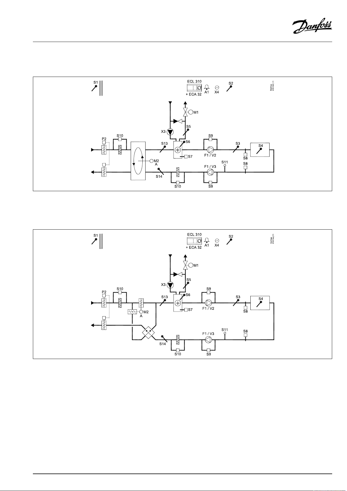
OperatingGuideECLComfort210/296/310,applicationA214/A314
A314.5examplea
Ventilationsystemwithheating,passivecooling(outsideair)androomtemperaturecontrol.Analogcontrolledspeedoffansinrelationto
airquality(CO2).Analogcontrolledspeedofrotaryheatexchanger(M2)forheatrecovery.
A314.5exampleb
Ventilationsystemwithheating,passivecooling(outsideair)androomtemperaturecontrol.Analogcontrolledspeedoffansinrelationto
airquality(CO2).Analogcontrolleddamper(M2)forheatrecoverybymeansofacrossheatexchanger.
AQ146286475947en-010601
©Danfoss|2021.06|47
Page 48

OperatingGuideECLComfort210/296/310,applicationA214/A314
A314.5examplec
Ventilationsystemwithheating,passivecooling(outsideair)androomtemperaturecontrol.Analogcontrolledspeedoffansinrelation
toairquality(CO2).Analogcontrolledspeedofrotaryheatexchanger(M2)forheatrecovery.ControlofNightdamperP8forreduced
ventilationduringsavingperiods.
A314.5exampled
Ventilationsystemwithheating,passivecooling(outsideair)androomtemperaturecontrol.Analogcontrolledspeedoffansinrelation
toairquality(CO2).Analogcontrolleddamper(M2)forheatrecoverybymeansofacrossheatexchanger.ControlofNightdamper
P8forreducedventilationduringsavingperiods.
48|©Danfoss|2021.06
AQ146286475947en-010601
Page 49
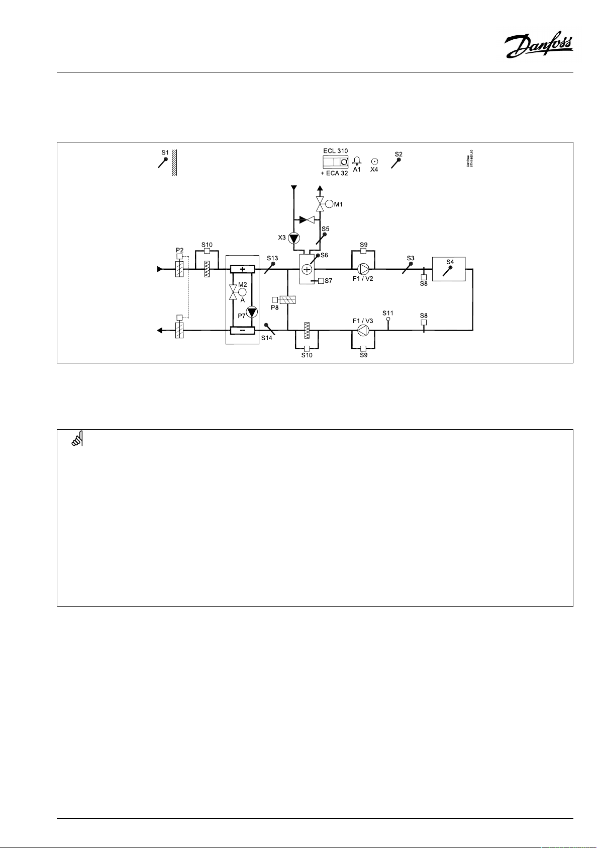
OperatingGuideECLComfort210/296/310,applicationA214/A314
A314.5examplee
Ventilationsystemwithheating,passivecooling(outsideair)androomtemperaturecontrol.Analogcontrolledspeedoffansinrelationto
airquality(CO2).Analogcontrolledvalve(M2)forheatrecoverybymeansofaFluidbattery.ControlofNightdamperP8forreduced
ventilationduringsavingperiods.
Sensoradvice:
SensorS3mustbeconnected.Ifnot,thefanF1stopsandmotorizedcontrolvalveM1closes.
S1,S13andS14mustbeconnectedinordertocalculatetherecoveryefficiency.
Navigation:
Specialsettingsforsensors/thermostatsusedasfrostprotection:
S6*frosttemperaturesensor—MENU\Alarm\FrostT\Alarmvalue
S5returntemperaturesensor—MENU\Alarm\LimitTfrost\Alarmvalue
ClosingcontactoftheS7*frostthermostat—MENU\Alarm\Frostthermostat\Alarmvalue
OpeningcontactoftheS7*frostthermostat—MENU\Alarm\Frostthermostat\Alarmvalue
*bothfrostprotectionmethods,bymeansofS6and/orS7,canbeused
Specialsettingsforthermostatsusedasfirealarm:
ClosingcontactoftheS8firethermostat—MENU\Alarm\Firesafety\Alarmvalue
OpeningcontactoftheS8firethermostat—MENU\Alarm\Firesafety\Alarmvalue
IDno.:
11676
11656
116160
11616
116360
11636
Recommended
setting:
5°C
5°C
1
1
AQ146286475947en-010601
©Danfoss|2021.06|49
Page 50

OperatingGuideECLComfort210/296/310,applicationA214/A314
A314.6examplea
Ventilationsystemwithheating,coolingandroomtemperaturecontrol.Analogcontrolledspeedoffansinrelationtopressures.Analog
controlledspeedofrotaryheatexchanger(M2)forheatrecovery.
A314.6exampleb
Ventilationsystemwithheating,coolingandroomtemperaturecontrol.Analogcontrolledspeedoffansinrelationtopressures.Analog
controlleddamper(M2)forheatrecoverybymeansofacrossheatexchanger.
50|©Danfoss|2021.06
AQ146286475947en-010601
Page 51
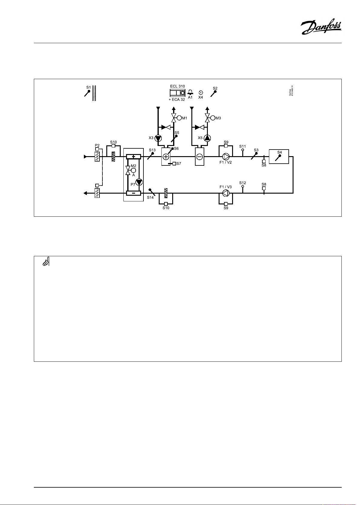
OperatingGuideECLComfort210/296/310,applicationA214/A314
A314.6examplec
Ventilationsystemwithheating,coolingandroomtemperaturecontrol.Analogcontrolledspeedoffansinrelationtopressures.Analog
controlledvalve(M2)forheatrecoverybymeansofaFluidbattery.
Sensoradvice:
SensorS3mustbeconnected.Ifnot,thefanF1stopsandmotorizedcontrolvalveM1closes.
S1,S13andS14mustbeconnectedinordertocalculatetherecoveryefficiency.
Navigation:
Specialsettingsforsensors/thermostatsusedasfrostprotection:
S6*frosttemperaturesensor—MENU\Alarm\FrostT\Alarmvalue
S5returntemperaturesensor—MENU\Alarm\LimitTfrost\Alarmvalue
ClosingcontactoftheS7*frostthermostat—MENU\Alarm\Frostthermostat\Alarmvalue
OpeningcontactoftheS7*frostthermostat—MENU\Alarm\Frostthermostat\Alarmvalue
*bothfrostprotectionmethods,bymeansofS6and/orS7,canbeused
Specialsettingsforthermostatsusedasfirealarm:
ClosingcontactoftheS8firethermostat—MENU\Alarm\Firesafety\Alarmvalue
OpeningcontactoftheS8firethermostat—MENU\Alarm\Firesafety\Alarmvalue
IDno.:
11676
11656
116160
11616
116360
11636
Recommended
setting:
5°C
5°C
1
1
AQ146286475947en-010601
©Danfoss|2021.06|51
Page 52

OperatingGuideECLComfort210/296/310,applicationA214/A314
A314.7examplea
Ventilationsystemwithheating,coolingandroomtemperaturecontrol.Analogcontrolledspeedoffansinrelationtoairquality(CO2).
Analogcontrolledspeedofrotaryheatexchanger(M2)forheatrecovery.
A314.7exampleb
Ventilationsystemwithheating,coolingandroomtemperaturecontrol.Analogcontrolledspeedoffansinrelationtoairquality(CO2).
Analogcontrolleddamper(M2)forheatrecoverybymeansofacrossheatexchanger.
52|©Danfoss|2021.06
AQ146286475947en-010601
Page 53
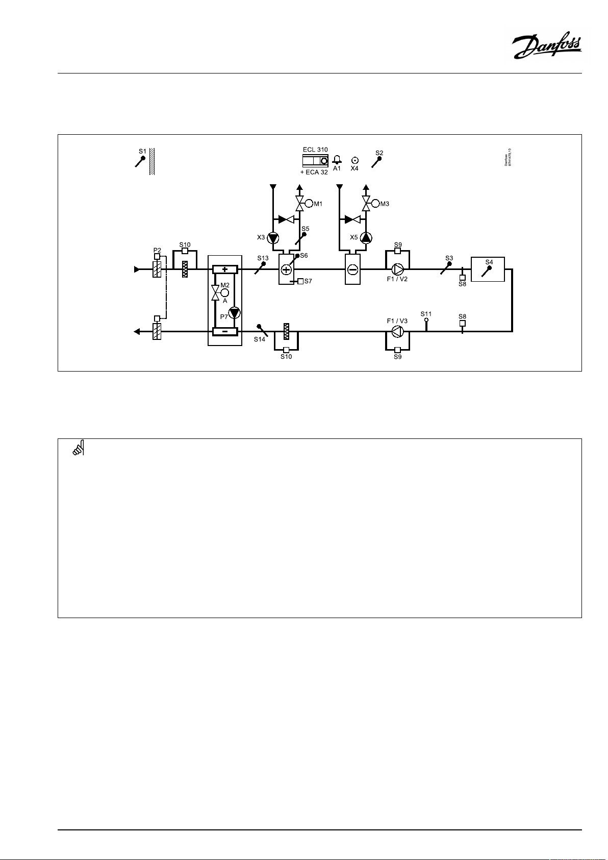
OperatingGuideECLComfort210/296/310,applicationA214/A314
A314.7examplec
Ventilationsystemwithheating,coolingandroomtemperaturecontrol.Analogcontrolledspeedoffansinrelationtoairquality(CO2).
Analogcontrolledvalve(M2)forheatrecoverybymeansofaFluidbattery.
Sensoradvice:
SensorS3mustbeconnected.Ifnot,thefanF1stopsandmotorizedcontrolvalveM1closes.
S1,S13andS14mustbeconnectedinordertocalculatetherecoveryefficiency.
Navigation:
Specialsettingsforsensors/thermostatsusedasfrostprotection:
S6*frosttemperaturesensor—MENU\Alarm\FrostT\Alarmvalue
S5returntemperaturesensor—MENU\Alarm\LimitTfrost\Alarmvalue
ClosingcontactoftheS7*frostthermostat—MENU\Alarm\Frostthermostat\Alarmvalue
OpeningcontactoftheS7*frostthermostat—MENU\Alarm\Frostthermostat\Alarmvalue
*bothfrostprotectionmethods,bymeansofS6and/orS7,canbeused
Specialsettingsforthermostatsusedasfirealarm:
ClosingcontactoftheS8firethermostat—MENU\Alarm\Firesafety\Alarmvalue
OpeningcontactoftheS8firethermostat—MENU\Alarm\Firesafety\Alarmvalue
IDno.:
11676
11656
116160
11616
116360
11636
Recommended
setting:
5°C
5°C
1
1
AQ146286475947en-010601
©Danfoss|2021.06|53
Page 54

OperatingGuideECLComfort210/296/310,applicationA214/A314
A314.9examplea
Ventilationsystemwithheatingandroomtemperaturecontrol.Analogcontrolledspeedoffansinrelationtoairquality(CO2).
54|©Danfoss|2021.06
AQ146286475947en-010601
Page 55

OperatingGuideECLComfort210/296/310,applicationA214/A314
A314.9exampleb
Ventilationsystemwithheatingandroomtemperaturecontrol.Analogcontrolledspeedoffansinrelationtoairquality(CO2).ON-OFF
controlofdamperP2.
Sensoradvice:
SensorS3mustbeconnected.Ifnot,thefanF1stopsandmotorizedcontrolvalveM1closes.
S1,S13andS14mustbeconnectedinordertocalculatetherecoveryefficiency.
Navigation:
Specialsettingsforsensors/thermostatsusedasfrostprotection:
S6*frosttemperaturesensor—MENU\Alarm\FrostT\Alarmvalue
S5returntemperaturesensor—MENU\Alarm\LimitTfrost\Alarmvalue
ClosingcontactoftheS7*frostthermostat—MENU\Alarm\Frostthermostat\Alarmvalue
OpeningcontactoftheS7*frostthermostat—MENU\Alarm\Frostthermostat\Alarmvalue
*bothfrostprotectionmethods,bymeansofS6and/orS7,canbeused
Specialsettingsforthermostatsusedasfirealarm:
ClosingcontactoftheS8firethermostat—MENU\Alarm\Firesafety\Alarmvalue
OpeningcontactoftheS8firethermostat—MENU\Alarm\Firesafety\Alarmvalue
IDno.:
11676
11656
116160
11616
116360
11636
Recommended
setting:
5°C
5°C
1
1
AQ146286475947en-010601
©Danfoss|2021.06|55
Page 56

OperatingGuideECLComfort210/296/310,applicationA214/A314
2.3Mounting
2.3.1MountingtheECLComfortcontroller
SeetheInstallationGuidewhichisdeliveredtogetherwiththe
ECLComfortcontroller.
Foreasyaccess,youshouldmounttheECLComfortcontrollernear
thesystem.
ECLComfort210/296/310canbemounted
•onawall
•onaDINrail(35mm)
ECLComfort296canbemounted
•inapanelcut-out
ECLComfort210canbemountedinanECLComfort310basepart
(forfutureupgrade).
Screws,PGcableglandsandrawlplugsarenotsupplied.
LockingtheECLComfort210/310controller
InordertofastentheECLComfortcontrollertoitsbasepart,secure
thecontrollerwiththelockingpin.
56|©Danfoss|2021.06
Topreventinjuriestopersonsorthecontroller,thecontrollerhasto
besecurelylockedintothebase.Forthispurpose,pressthelocking
pinintothebaseuntilaclickisheardandthecontrollernolonger
canberemovedfromthebase.
Ifthecontrollerisnotsecurelylockedintothebasepart,thereisarisk
thatthecontrollerduringoperationcanunlockfromthebaseandthe
basewithterminals(andalsothe230Va.c.connections)areexposed.
Topreventinjuriestopersons,alwaysmakesurethatthecontroller
issecurelylockedintoitsbase.Ifthisisnotthecase,thecontroller
shouldnotbeoperated!
AQ146286475947en-010601
Page 57
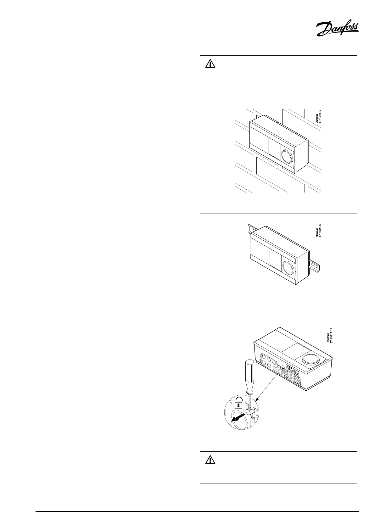
OperatingGuideECLComfort210/296/310,applicationA214/A314
Mountingonawall
Mountthebasepartonawallwithasmoothsurface.Establishthe
electricalconnectionsandpositionthecontrollerinthebasepart.
Securethecontrollerwiththelockingpin.
MountingonaDINrail(35mm)
MountthebasepartonaDINrail.Establishtheelectrical
connectionsandpositionthecontrollerinthebasepart.Secure
thecontrollerwiththelockingpin.
Theeasywaytolockthecontrollertoitsbaseorunlockitistousea
screwdriveraslever.
DismountingtheECLComfortcontroller
Inordertoremovethecontrollerfromthebasepart,pulloutthe
lockingpinbymeansofascrewdriver.Thecontrollercannowbe
removedfromthebasepart.
Theeasywaytolockthecontrollertoitsbaseorunlockitistousea
screwdriveraslever.
AQ146286475947en-010601
©Danfoss|2021.06|57
Page 58

OperatingGuideECLComfort210/296/310,applicationA214/A314
2.3.2MountingtheRemoteControlUnitsECA30/31
Selectoneofthefollowingmethods:
•Mountingonawall,ECA30/31
•Mountinginapanel,ECA30
Screwsandrawlplugsarenotsupplied.
Mountingonawall
MountthebasepartoftheECA30/31onawallwithasmooth
surface.Establishtheelectricalconnections.PlacetheECA30/
31inthebasepart.
BeforeremovingtheECLComfortcontrollerfromthebasepart,ensure
thatthesupplyvoltageisdisconnected.
Mountinginapanel
MounttheECA30inapanelusingtheECA30framekit(ordercode
no.087H3236).Establishtheelectricalconnections.Securethe
framewiththeclamp.PlacetheECA30inthebasepart.TheECA
30canbeconnectedtoanexternalroomtemperaturesensor.
TheECA31mustnotbemountedinapanelifthehumidity
functionistobeused.
58|©Danfoss|2021.06
AQ146286475947en-010601
Page 59

OperatingGuideECLComfort210/296/310,applicationA214/A314
2.3.3MountingtheinternalI/OmoduleECA32
MountingoftheinternalI/OmoduleECA32
TheECA32module(ordercodeno.087H3202)mustbeinserted
intotheECLComfort310/310Bbasepartforadditionalinputand
outputsignalsinrelevantapplications.
TheconnectionbetweentheECLComfort310/310BandECA32
isa10-pole(2x5)connector.Theconnectionisautomatically
establishedwhentheECLComfort310/310Bisplacedonthe
basepart.
AQ146286475947en-010601
©Danfoss|2021.06|59
Page 60
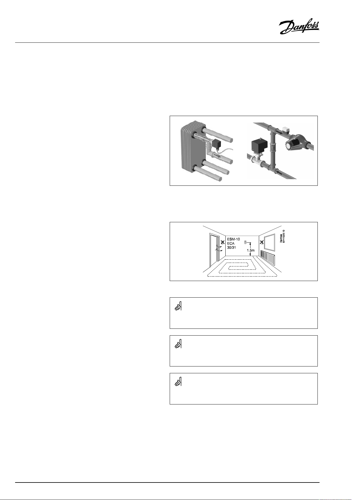
OperatingGuideECLComfort210/296/310,applicationA214/A314
2.4Placingthetemperaturesensors
Itisimportantthatthesensorsaremountedinthecorrectposition
inyoursystem.
Thetemperaturesensormentionedbelowaresensorsusedforthe
ECLComfort210/296/310serieswhichnotallwillbeneeded
foryourapplication!
Outdoortemperaturesensor(ESMT)
Theoutdoorsensorshouldbemountedonthatsideofthebuilding
whereitislesslikelytobeexposedtodirectsunshine.Itshouldnot
beplacedclosetodoors,windowsorairoutlets.
Flowtemperaturesensor(ESMU,ESM-11orESMC)
Placethesensormax.15cmfromthemixingpoint.Insystems
withheatexchanger,DanfossrecommendsthattheESMU-typeto
beinsertedintotheexchangerflowoutlet.
Makesurethatthesurfaceofthepipeiscleanandevenwhere
thesensorismounted.
Returntemperaturesensor(ESMU,ESM-11orESMC)
Thereturntemperaturesensorshouldalwaysbeplacedsothatit
measuresarepresentativereturntemperature.
Roomtemperaturesensor
(ESM-10,ECA30/31RemoteControlUnit)
Placetheroomsensorintheroomwherethetemperatureistobe
controlled.Donotplaceitonoutsidewallsorclosetoradiators,
windowsordoors.
Boilertemperaturesensor(ESMU,ESM-11orESMC)
Placethesensoraccordingtotheboilermanufacturer’s
specification.
Airducttemperaturesensor(ESMB-12orESMUtypes)
Placethesensorsothatitmeasuresarepresentativetemperature.
DHWtemperaturesensor(ESMUorESMB-12)
PlacetheDHWtemperaturesensoraccordingtothemanufacturer’s
specification.
Slabtemperaturesensor(ESMB-12)
Placethesensorinaprotectiontubeintheslab.
ESM-11:Donotmovethesensorafterithasbeenfastenedinorderto
avoiddamagetothesensorelement.
ESM-11,ESMCandESMB-12:Useheatconductingpasteforquick
measurementofthetemperature.
ESMUandESMB-12:Usingasensorpockettoprotectthesensorwill,
however,resultinaslowertemperaturemeasurement.
60|©Danfoss|2021.06
AQ146286475947en-010601
Page 61
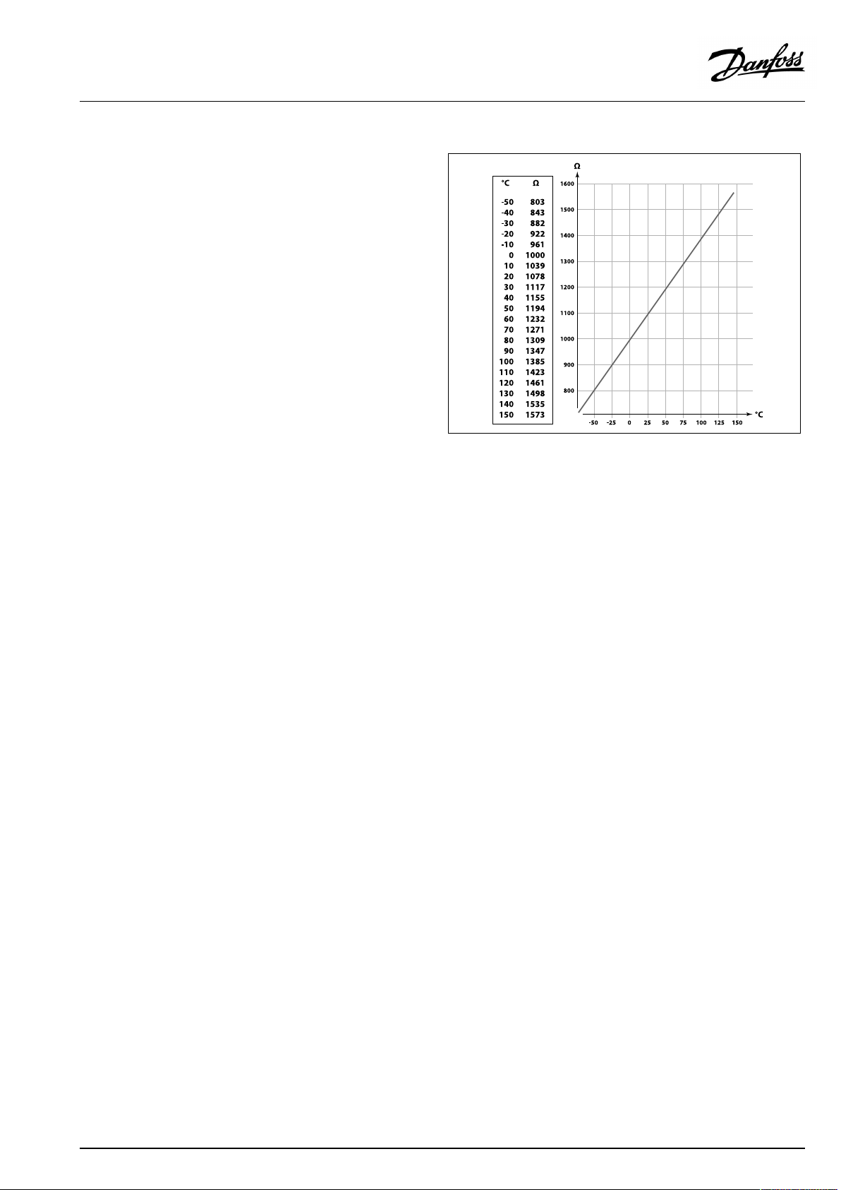
OperatingGuideECLComfort210/296/310,applicationA214/A314
Pt1000temperaturesensor(IEC751B,1000Ω/0°C)
Relationshipbetweentemperatureandohmicvalue:
AQ146286475947en-010601
©Danfoss|2021.06|61
Page 62

OperatingGuideECLComfort210/296/310,applicationA214/A314
2.5Electricalconnections
2.5.1Electricalconnections230Va.c.
Warning
ElectricconductorsonPCB(PrintedCircuitBoard)forsupplyvoltage,
relaycontactsandtriacoutputsdonothavemutualsafetydistanceof
minimum6mm.Theoutputsarenotallowedtobeusedasgalvanic
separated(voltfree)outputs.
Ifagalvanicseparatedoutputisneeded,anauxiliaryrelayis
recommended.
24Voltcontrolledunits,forexampleactuators,aretobecontrolledby
meansofECLComfort310,24Voltversion.
SafetyNote
Necessaryassembly,start-up,andmaintenanceworkmustbe
performedbyqualifiedandauthorizedpersonnelonly.
Locallegislationsmustberespected.Thiscomprisesalsocablesize
andisolation(reinforcedtype).
AfusefortheECLComfortinstallationismax.10Atypically.
TheambienttemperaturerangefortheECLComfortinoperationis
0-55°C.Exceedingthistemperaturerangecanresultinmalfunctions.
Installationmustbeavoidedifthereisariskforcondensation(dew).
62|©Danfoss|2021.06
AQ146286475947en-010601
Page 63
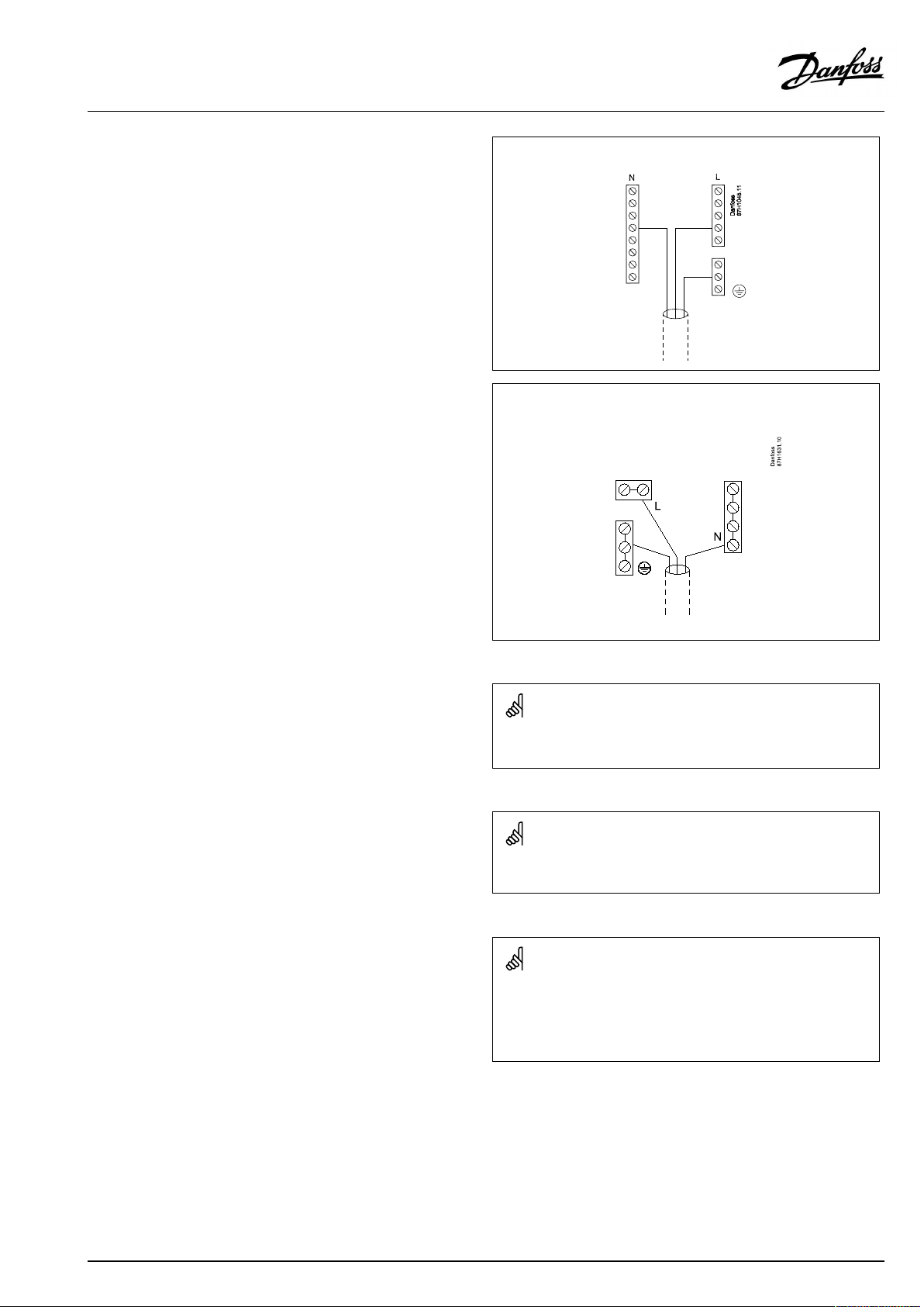
OperatingGuideECLComfort210/296/310,applicationA214/A314
Thecommongroundterminalisusedforconnectionofrelevant
components(pumps,motorizedcontrolvalves).
ECL210/310
ECL296
Factoryestablishedjumpersinthebasepart:
5to8,9to14,Lto5andLto9,Nto10
SeealsotheA214InstallationGuide(deliveredwiththeapplication
key)forapplicationspecificconnections.
Electricalconnections,230Va.c.,powersupply,pumps,dampers,
motorizedcontrolvalvesetc.
Connections,ingeneral:
SeealsotheA214InstallationGuide(deliveredwiththeapplication
key)forapplicationspecificconnections.
AQ146286475947en-010601
©Danfoss|2021.06|63
Page 64

OperatingGuideECLComfort210/296/310,applicationA214/A314
2.5.2Electricalconnections,230Va.c.,powersupply,pumps,dampers,motorizedcontrolvalvesetc.
Connections,ingeneral.
SeealsotheInstallationGuide(deliveredwiththeapplicationkey)forapplicationspecificconnections.
TerminalsMax.load
ECL210ECL310
19
18
17
1616
15
1414
13
12
15
13
12
4(2)A/230Va.c.*
4(2)A/230Va.c.*
4(2)A/230Va.c.*
4(2)A/230Va.c.*
4(2)A/230Va.c.*
11
10
9
88
7
6
55
4
3
*4Aforohmicload,2Aforinductiveload
Factoryestablishedjumpersinthebasepart:
5to8,9to14,Lto5andLto9,Nto10
11
10
9
7
6
4
3
2
1
230Va.c.,Neutral(N)
230Va.c.,Live(L)
4(2)A/230Va.c.*
0,2A/230Va.c.
0,2A/230Va.c.
0,2A/230Va.c.
0,2A/230Va.c.
0,2A/230Va.c.
0,2A/230Va.c.
64|©Danfoss|2021.06
AQ146286475947en-010601
Page 65

OperatingGuideECLComfort210/296/310,applicationA214/A314
Electricalconnections,ECA32
Connections,ingeneral.
SeealsotheA214InstallationGuide(deliveredwiththeapplicationkey)forapplicationspecificconnections.
TerminalsMax.load
ECA32
48
47
46
45
44
43
42
41
4(2)A/230Va.c.*
4(2)A/230Va.c.*
4(2)A/230Va.c.*
4(2)A/230Va.c.*
4(2)A/230Va.c.*
40
39
*4Aforohmicload,2Aforinductiveload
4(2)A/230Va.c.*
Wirecrosssection:0.5-1.5mm²
Incorrectconnectioncandamagetheelectronicoutputs.
Max.2x1.5mm²wirescanbeinsertedintoeachscrewterminal.
AQ146286475947en-010601
©Danfoss|2021.06|65
Page 66

OperatingGuideECLComfort210/296/310,applicationA214/A314
2.5.3Electricalconnections,24Va.c.,powersupply,pumps,dampers,motorizedcontrolvalvesetc.
Connections,ingeneral.
SeealsotheA214InstallationGuide(deliveredwiththeapplicationkey)forapplicationspecificconnections.
DonotuseacommontransformerforECLComfort310andmotorizedvalve/dampercontrol.Useseparatetransformers.
TerminalsMax.load
ECA310
19
18
17
16
15
14
13
12
11
10
9
8
7
6
5
4
3
2
1
*4Aforohmicload,2Aforinductiveload
24Va.c.,(SN)
24Va.c.,(SP)
4(2)A/24Va.c.*
4(2)A/24Va.c.*
4(2)A/24Va.c.*
4(2)A/24Va.c.*
4(2)A/24Va.c.*
4(2)A/24Va.c.*
1A/24Va.c.
1A/24Va.c.
1A/24Va.c.
1A/24Va.c.
1A/24Va.c.
1A/24Va.c.
Factoryestablishedjumpersinthebasepart:
5to8,9to14,L(SP)to5andL(SP)to9,N(SN)to10
66|©Danfoss|2021.06
AQ146286475947en-010601
Page 67

OperatingGuideECLComfort210/296/310,applicationA214/A314
Donotconnect230Va.c.poweredcomponentstoa24Va.c.power
suppliedcontrollerdirectly.Useauxilliaryrelays(K)toseparate230
Va.c.from24Va.c.
Wirecrosssection:0.5-1.5mm²
Incorrectconnectioncandamagetheelectronicoutputs.
Max.2x1.5mm²wirescanbeinsertedintoeachscrewterminal.
AQ146286475947en-010601
©Danfoss|2021.06|67
Page 68

OperatingGuideECLComfort210/296/310,applicationA214/A314
Electricalconnections,ECA32
Connections,ingeneral.
SeealsotheA214InstallationGuide(deliveredwiththeapplicationkey)forapplicationspecificconnections.
TerminalsMax.load
ECA32
48
47
46
45
44
43
42
41
4(2)A/230Va.c.*
4(2)A/230Va.c.*
4(2)A/230Va.c.*
4(2)A/230Va.c.*
4(2)A/230Va.c.*
40
39
*4Aforohmicload,2Aforinductiveload
4(2)A/230Va.c.*
68|©Danfoss|2021.06
AQ146286475947en-010601
Page 69

OperatingGuideECLComfort210/296/310,applicationA214/A314
Electricalconnections,ECA32
Connections,ingeneral.
SeealsotheA214InstallationGuide(deliveredwiththeapplicationkey)forapplicationspecificconnections.
Thetransformersforsupplyingtheactuatorsmustbedouble-isolatedversions.
TerminalsMax.load
ECA32
56
57
58
59
60
61
62
*Thevaluemustbe47kΩasaminimum.
47kΩ*
47kΩ*
47kΩ*
AQ146286475947en-010601
©Danfoss|2021.06|69
Page 70

OperatingGuideECLComfort210/296/310,applicationA214/A314
ExampleshowingseparatetransformersforECL310supplyandoutputconnections:
AMD=Danfossdamperactuator
ExampleshowingsupplyforECL310andoutputconnections:
VSD=VariableSpeedDrive
ExampleshowingsupplyforECL310,24Va.c.
Separatetransformerforsupplyoftransmitter(forinput)andoutputconnections:
AMD=Danfossdamperactuator
70|©Danfoss|2021.06
AQ146286475947en-010601
Page 71

OperatingGuideECLComfort210/296/310,applicationA214/A314
2.5.4Electricalconnections,Pt1000temperaturesensors
A214/A314:
TerminalSensor/description
29and30
28and30
27and30
26and30
25and30
24and30
23and30
22and30
21and30
20and30
S1
Outdoortemp.sensor*
S2Compensationtemp.
sensor**
S3
Airduct/flowtemp.sensor
***
A214.1,A214.3,A214.5,
S4
A214.6,A314.2-A314.9:
Roomtemp.sensor.
A214.2,A214.4,A314.1:
Flowtemp.sensor.
S5Returntemp.sensor
S6
Frosttemp.sensor****
(notusedinA214.1)
S7
Frostthermostat*****
S8
Firethermostat*****
S9
ECL310only.
A314.4-A314.9:
Fanmonitor
S10
ECL310only.
A314.3:Windspeedsignal
(0-10V).
Type
(recomm.)
ESMT
ESM-11/ESMB
/
ESMC/ESMU/
ESMT
ESM-11/ESMB
/
ESMC/ESMU
ESM-10
ESM-11/ESMB
/
ESMC/ESMU
ESM-11/ESMB
/
ESMC/ESMU
ESMB
A314.4-A314.9:
Filtermonitor
*
Iftheoutdoortemperaturesensorisnotconnectedorthe
cableisshort-circuited,thecontrollerassumesthatthe
outdoortemperatureis0(zero)°C.
**
Couldforexamplebeanextraroomtemperaturesensor.
***
Ifthesensorisnotconnectedorthecableisshort-circuited,
themotorizedcontrolvalvecloses(safetyfunction).
****
Bothfrostprotectionmethodscanbeused.
*****
Canbesetuptoreactonaclosingoranopeningcontact.
Factoryestablishedjumper:
30tocommonterminal.
Wirecrosssectionforsensorconnections:Min.0.4mm².
Totalcablelength:Max.200m(allsensorsincl.internalECL485
communicationbus)
Cablelengthsofmorethan200mmaycausenoisesensibility(EMC).
AQ146286475947en-010601
©Danfoss|2021.06|71
Page 72

OperatingGuideECLComfort210/296/310,applicationA214/A314
Overridecontact
Exampleofoverridecontact,connectedtoS8:
72|©Danfoss|2021.06
AQ146286475947en-010601
Page 73

OperatingGuideECLComfort210/296/310,applicationA214/A314
Connectionoffrostthermostats,S7
Whenfrost(toolowtemperature)isdetected,contacts1-2close.
Whenfrost(toolowtemperature)isdetected,contacts1-4open.
ConnectionsofFanandFiltermonitor(S9andS10):
Wirecrosssection:0.5-1.5mm²
Incorrectconnectioncandamagetheelectronicoutputs.
Max.2x1.5mm²wirescanbeinsertedintoeachscrewterminal.
AQ146286475947en-010601
©Danfoss|2021.06|73
Page 74
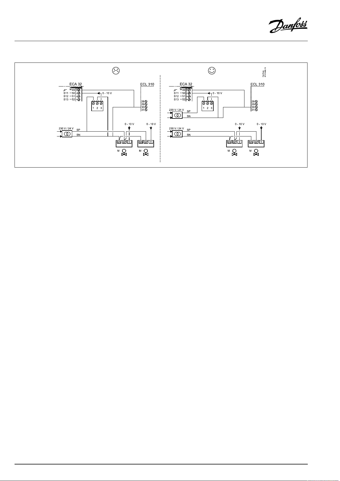
OperatingGuideECLComfort210/296/310,applicationA214/A314
Donotusecommontransformerwhenpressuretransmittersaresuppliedby24Va.c.:
74|©Danfoss|2021.06
AQ146286475947en-010601
Page 75

OperatingGuideECLComfort210/296/310,applicationA214/A314
ConnectionsofinputsS11,S12,S13andS14
(S11andS12transmittersgenerate0-10V)
(S11andS12transmittersgenerate4-20mA)
ExampleshowingsupplyforECL310,24Va.c.
Separatetransformerforsupplyoftransmitter(forinput)and
outputconnections.
AMD=Danfossdamperactuator
AQ146286475947en-010601
©Danfoss|2021.06|75
Page 76

OperatingGuideECLComfort210/296/310,applicationA214/A314
2.5.5Electricalconnections,ECA30/31
Terminal
ECL
Terminal
ECA30/31
30
31
4
1
322
333
4
5
*
Afteranexternalroomtemperaturesensorhasbeenconnected,
Description
Twistedpair
Twistedpair
Ext.roomtemperature
sensor*
Type
(recomm.)
Cable2x
twistedpair
ESM-10
ECA30/31mustberepowered.
ThecommunicationtotheECA30/31mustbesetupintheECL
Comfortcontrollerin'ECAaddr.'
TheECA30/31mustbesetupaccordingly.
AfterapplicationsetuptheECA30/31isreadyafter2–5min.A
progressbarintheECA30/31isdisplayed.
76|©Danfoss|2021.06
Max.2ECA30/31canbeconnectedtoanECLComfort310controller
ortoECLComfort210/296/310controllersinamaster-slavesystem.
SetupproceduresforECA30/31:Seesection‘Miscellaneous’ .
ECAinformationmessage:
‘Applicationreq.newerECA’:
Thesoftware(firmware)ofyourECAdoesnotcomplywiththe
software(firmware)ofyourECLComfortcontroller.Pleasecontact
yourDanfosssalesoffice.
AQ146286475947en-010601
Page 77

OperatingGuideECLComfort210/296/310,applicationA214/A314
Someapplicationsdonotcontainfunctionsrelatedtoactualroom
temperature.TheconnectedECA30/31willonlyfunctionasremote
control.
AQ146286475947en-010601
©Danfoss|2021.06|77
Page 78

OperatingGuideECLComfort210/296/310,applicationA214/A314
2.5.6Electricalconnections,master/slavesystems
Thecontrollercanbeusedasmasterorslaveinmaster/slave
systemsviatheinternalECL485communicationbus(2xtwisted
paircable).
TheECL485communicationbusisnotcompatiblewiththeECL
businECLComfort110,200,300and301!
Terminal
Description
Type
(recomm.)
30
Commonterminal
+12V*,ECL485communicationbus
31
*OnlyforECA30/31andmaster/
slavecommunication
32
B,ECL485communicationbus
33
A,ECL485communicationbus
Cable2x
twistedpair
Totalcablelength:Max.200m(allsensorsincl.internalECL485
communicationbus).
Cablelengthsofmorethan200mmaycausenoisesensibility(EMC).
ECL485buscable
MaximumrecommendedlengthoftheECL485busiscalculatedlike
this:
Subtract"TotallengthofallinputcablesofallECLcontrollersinthe
master-slavesystem"from200m.
2.5.7Electricalconnections,communication
Electricalconnections,Modbus
ECLComfort210:Non-galvanicisolatedModbusconnections
ECLComfort296:GalvanicisolatedModbusconnections
ECLComfort310:GalvanicisolatedModbusconnections
Simpleexamplefortotallengthofallinputcables,3xECL:
1xECL
3xECL
3xECLReturntemp.sensor:
3xECLRoomtemp.sensor:
Total:
MaximumrecommendedlengthoftheECL485bus:
200-81m=119m
Outdoortemp.sensor:
Flowtemp.sensor:
15m
18m
18m
30m
81m
78|©Danfoss|2021.06
AQ146286475947en-010601
Page 79

OperatingGuideECLComfort210/296/310,applicationA214/A314
2.5.8Electricalconnections,communication
Electricalconnections,M-bus
ECLComfort210:Notimplemented
ECLComfort296:Onboard,non-galvanicisolated.Max.cable
length50m.
ECLComfort310:Onboard,non-galvanicisolated.Max.cable
length50m.
AQ146286475947en-010601
©Danfoss|2021.06|79
Page 80

OperatingGuideECLComfort210/296/310,applicationA214/A314
2.6InsertingtheECLApplicationKey
2.6.1InsertingtheECLApplicationKey
TheECLApplicationKeycontains
•theapplicationanditssubtypes,
•currentlyavailablelanguages,
•factorysettings:e.g.schedules,desiredtemperatures,
limitationvaluesetc.Itisalwayspossibletorecoverthefactory
settings,
•memoryforusersettings:specialuser/systemsettings.
Afterhavingpowered-upthecontroller,differentsituationsmight
beexisting:
1.Thecontrollerisnewfromthefactory,theECLApplicationKey
isnotinserted.
2.Thecontrolleralreadyrunsanapplication.TheECLApplication
Keyisinserted,buttheapplicationneedstobechanged.
3.Acopyofthecontrollerssettingsisneededforconfiguring
anothercontroller.
ECLComfort210/310
ECLComfort210/310
Usersettingsare,amongothers,desiredroomtemperature,desired
DHWtemperature,schedules,heatcurve,limitationvaluesetc.
Systemsettingsare,amongothers,communicationset-up,display
brightnessetc.
80|©Danfoss|2021.06
ECLComfort296
AQ146286475947en-010601
Page 81

OperatingGuideECLComfort210/296/310,applicationA214/A314
Automaticupdateofcontrollersoftware(firmware):
Thesoftwareofthecontrollerisupdatedautomaticallywhenthekey
isinserted(asofcontrollerversion1.11(ECL210/310)andversion
1.58(ECL296)).Thefollowinganimationwillbeshownwhenthe
softwareisbeingupdated:
Progressbar
Duringupdate:
•DonotremovetheKEY
Ifthekeyisremovedbeforethehour-glassisshown,youhave
tostartafresh.
•Donotdisconnectthepower
Ifthepowerisinterruptedwhenthehour-glassisshown,the
controllerwillnotwork.
•Manualupdateofcontrollersoftware(firmware):
Seethesection"Automatic/manualupdateoffirmware"
The“Keyoverview”doesnotinform—throughECA30/31—about
thesubtypesoftheapplicationkey.
Keyinserted/notinserted,description:
ECLComfort210/310,controllerversionslowerthan1.36:
-
Takeouttheapplicationkey;for20minutes
settingscanbechanged.
-
Powerupthecontrollerwithoutthe
applicationkeyinserted;for20minutes
settingscanbechanged.
ECLComfort210/310,controllerversions1.36andup:
-
Takeouttheapplicationkey;for20minutes
settingscanbechanged.
-
Powerupthecontrollerwithoutthe
applicationkeyinserted;settingscannotbe
changed.
ECLComfort296,controllerversions1.58andup:
-
Takeouttheapplicationkey;for20minutes
settingscanbechanged.
-
Powerupthecontrollerwithoutthe
applicationkeyinserted;settingscannotbe
changed.
AQ146286475947en-010601
©Danfoss|2021.06|81
Page 82
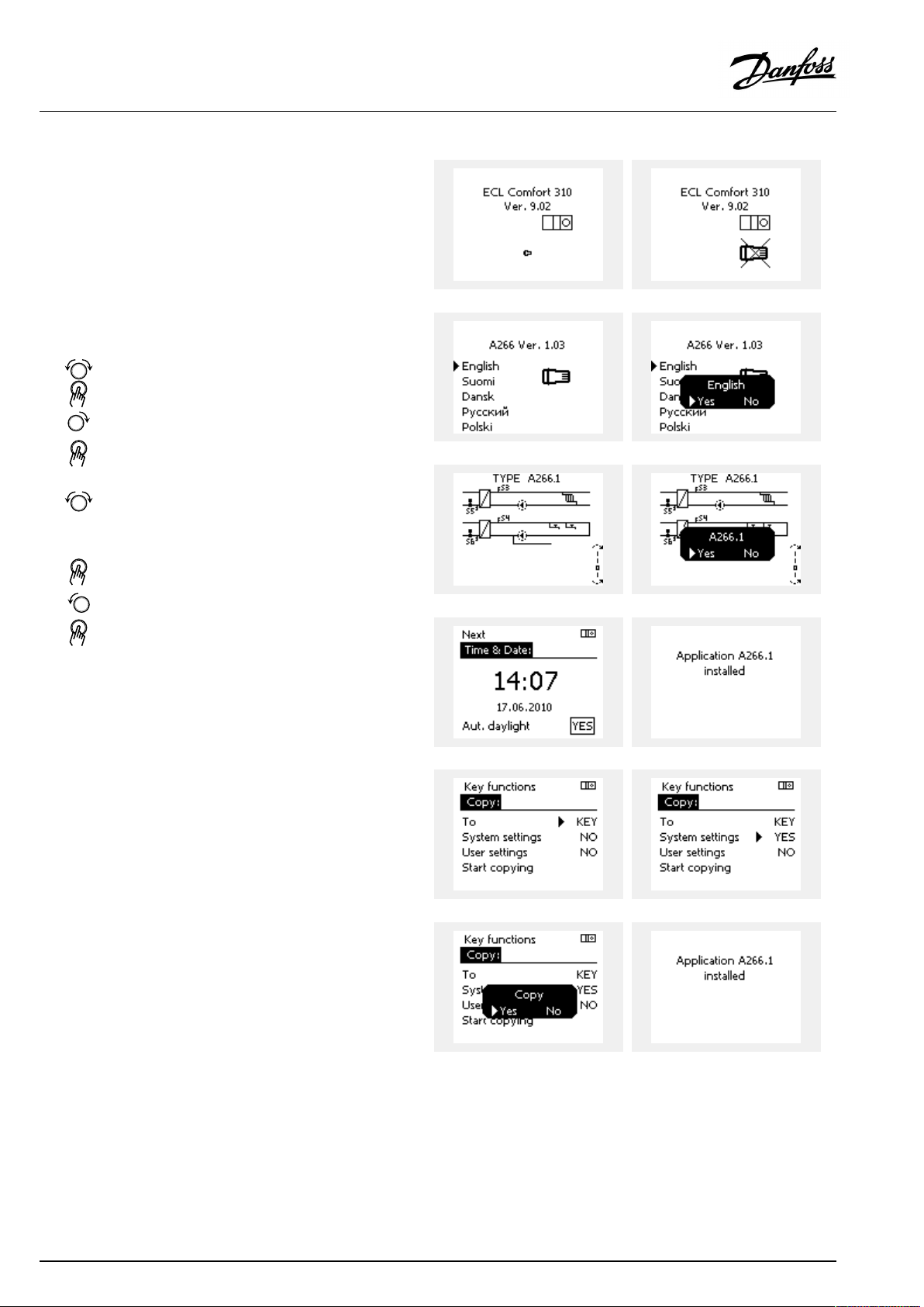
OperatingGuideECLComfort210/296/310,applicationA214/A314
ApplicationKey:Situation1
Thecontrollerisnewfromthefactory,theECLApplicationKey
isnotinserted.
AnanimationfortheECLApplicationKeyinsertionisdisplayed.
InserttheApplicationKey.
ApplicationKeynameandVersionisindicated(example:A266
Ver.1.03).
IftheECLApplicationKeyisnotsuitableforthecontroller,a"cross"
isdisplayedovertheECLApplicationKey-symbol.
Action:Purpose:
Selectlanguage
Confirm
Selectapplication(subtype)
Somekeyshaveonlyoneapplication.
Confirmwith‘Yes’
Set'Time&Date'
Turnandpushthedialtoselectand
change'Hours' ,'Minutes','Date',
'Month'and'Year' .
Choose''Next'
Confirmwith‘Yes’
Goto‘Aut.daylight’
Choosewhether‘ Aut.daylight´*
shouldbeactiveornot
*‘Aut.daylight’istheautomaticchangeoverbetweensummer
andwintertime.
DependingonthecontentsoftheECLApplicationKey,procedure
AorBistakingplace:
A
TheECLApplicationkeycontainsfactorysettings:
Thecontrollerreads/transfersdatafromtheECLApplicationKey
toECLcontroller.
Examples:
YESorNO
Theapplicationisinstalled,andthecontrollerresetsandstartsup.
B
TheECLApplicationkeycontainschangedsystemsettings:
Pushthedialrepeatedly.
’NO’:
’YES*:
Ifthekeycontainsusersettings:
Pushthedialrepeatedly.
‘NO:
‘YES*:
*If‘YES’cannotbechosen,theECLApplicationKeydoesnot
containanyspecialsettings.
Choose‘Startcopying’andconfirmwith'Yes'.
82|©Danfoss|2021.06
OnlyfactorysettingsfromtheECLApplicationKeywill
becopiedtothecontroller.
Specialsystemsettings(differingfromthefactory
settings)willbecopiedtothecontroller.
OnlyfactorysettingsfromtheECLApplicationKeywill
becopiedtothecontroller.
Specialusersettings(differingfromthefactorysettings)
willbecopiedtothecontroller.
AQ146286475947en-010601
Page 83

OperatingGuideECLComfort210/296/310,applicationA214/A314
(Example):
The"i"intheupperrightcornerindicatesthat-besidesthefactory
settings-thesubtypealsocontainsspecialuser/systemssettings.
ApplicationKey:Situation2
Thecontrolleralreadyrunsanapplication.TheECLApplication
Keyisinserted,buttheapplicationneedstobechanged.
TochangetoanotherapplicationontheECLApplicationKey,the
currentapplicationinthecontrollermustbeerased(deleted).
BeawarethattheApplicationKeymustbeinserted.
Action:Purpose:
Choose‘MENU’inanycircuit
Confirm
Choosethecircuitselectoratthetop
rightcornerinthedisplay
Confirm
Choose‘Commoncontrollersettings’
Confirm
Choose‘Keyfunctions’
Confirm
Choose‘Eraseapplication’
Confirmwith‘Yes’
Thecontrollerresetsandisreadytobeconfigured.
Followtheproceduredescribedinsituation1.
Examples:
AQ146286475947en-010601
©Danfoss|2021.06|83
Page 84
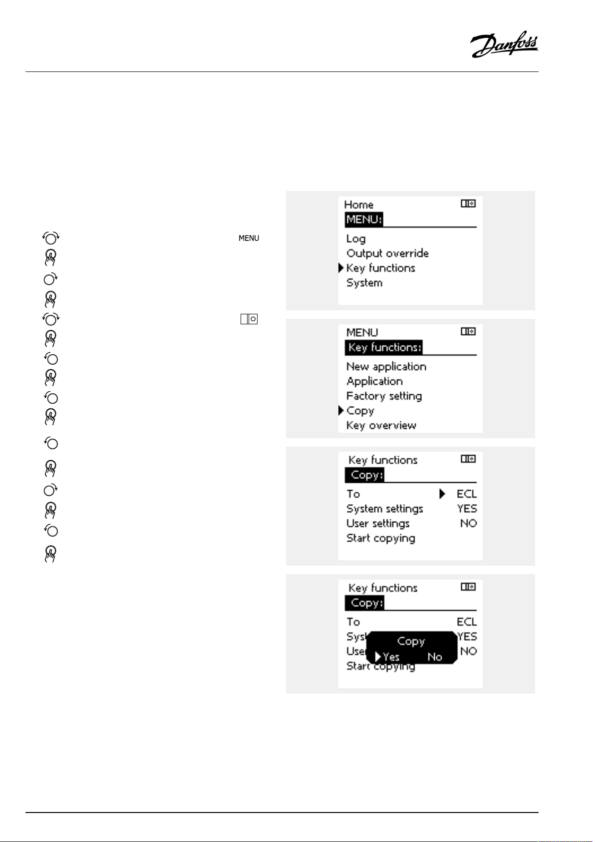
OperatingGuideECLComfort210/296/310,applicationA214/A314
ApplicationKey:Situation3
Acopyofthecontrollerssettingsisneededforconfiguring
anothercontroller.
Thisfunctionisused
•forsaving(backup)ofspecialuserandsystemsettings
•whenanotherECLComfortcontrollerofthesametype(210,
296or310)mustbeconfiguredwiththesameapplicationbut
user/systemsettingsdifferfromthefactorysettings.
HowtocopytoanotherECLComfortcontroller:
Action:Purpose:
Choose‘MENU’
Confirm
Choosethecircuitselectoratthetop
rightcornerinthedisplay
Confirm
Choose'Commoncontrollersettings'
Confirm
Goto‘Keyfunctions’
Confirm
Choose‘Copy’
Confirm
Choose‘To’ .
‘ECL’or‘KEY’willbeindicated.Choose
’ECL’orKEY’
Pushthedialrepeatedlytochoose
copydirection
Choose‘Systemsettings’or‘User
settings’
Pushthedialrepeatedlytochoose
‘Yes’or‘No’in‘Copy’ .Pushtoconfirm.
Choose‘Startcopying’
TheApplicationKeyorthecontroller
isupdatedwithspecialsystemoruser
settings.
Examples:
*
’ECL’or‘KEY’ .
**
‘NO’or‘YES’
*
‘ECL’:
‘KEY’:
**
‘NO’:
‘YES’:
84|©Danfoss|2021.06
DatawillbecopiedfromtheApplicationKeytothe
ECLController.
DatawillbecopiedfromtheECLControllertothe
ApplicationKey.
ThesettingsfromtheECLcontrollerwillnotbecopied
totheApplicationKeyortotheECLComfortcontroller.
Specialsettings(differingfromthefactorysettings)will
becopiedtotheApplicationKeyortotheECLComfort
controller.IfYEScannotbechosen,therearenospecial
settingstobecopied.
AQ146286475947en-010601
Page 85
OperatingGuideECLComfort210/296/310,applicationA214/A314
Language
Atapplicationupload,alanguagemustbeselected.*
IfanotherlanguagethanEnglishisselected,theselectedlanguage
ANDEnglishwillbeuploadedintotheECLcontroller.
ThismakesserviceeasyforEnglishspeakingservicepeople,just
becausetheEnglishlanguagemenuscanbevisiblebychanging
theactualsetlanguageintoEnglish.
(Navigation:MENU>Commoncontroller>System>Language)
Iftheuploadedlanguageisnotsuitable,theapplicationmustbe
erased.UserandSystemsettingscanbesavedontheapplication
keybeforeerasing.
Afternewuploadwithpreferredlanguage,theexistingUserand
Systemsettingscanbeuploaded.
*)
(ECLComfort310,24Volt)Iflanguagecannotbeselected,the
powersupplyisnota.c.(alternatingcurrent).
2.6.2ECLApplicationKey,copyingdata
Generalprinciples
Whenthecontrollerisconnectedandoperating,youcancheck
andadjustallorsomeofthebasicsettings.Thenewsettingscan
bestoredontheKey.
Factorysettingscanalwaysberestored.
HowtoupdatetheECLApplicationKeyaftersettingshave
beenchanged?
AllnewsettingscanbestoredontheECLApplicationKey.
Howtostorefactorysettinginthecontrollerfromthe
ApplicationKey?
PleasereadtheparagraphconcerningApplicationKey,Situation
1:Thecontrollerisnewfromthefactory,theECLApplicationKey
isnotinserted.
HowtostorepersonalsettingsfromthecontrollertotheKey?
PleasereadtheparagraphconcerningApplicationKey,Situation3:
Acopyofthecontrollerssettingsisneededforconfiguringanother
controller
Asamainrule,theECLApplicationKeyshouldalwaysremainin
thecontroller.IftheKeyisremoved,itisnotpossibletochange
settings.
Makeanoteofnewsettingsinthe'Settingsoverview'table.
DonotremovetheECLApplicationKeywhilecopying.Thedataon
theECLApplicationKeycanbedamaged!
ItispossibletocopysettingsfromoneECLComfortcontrollerto
anothercontrollerprovidedthatthetwocontrollersarefromthesame
series(210or310).
Furthermore,whentheECLComfortcontrollerhasbeenuploaded
withanapplicationkey,minimumversion2.44,itispossibletoupload
personalsettingsfromapplicationkeys,minimumversion2.14.
AQ146286475947en-010601
©Danfoss|2021.06|85
Page 86

OperatingGuideECLComfort210/296/310,applicationA214/A314
The“Keyoverview”doesnotinform—throughECA30/31—about
thesubtypesoftheapplicationkey.
Keyinserted/notinserted,description:
ECLComfort210/310,controllerversionslowerthan1.36:
-
Takeouttheapplicationkey;for20minutes
settingscanbechanged.
-
Powerupthecontrollerwithoutthe
applicationkeyinserted;for20minutes
settingscanbechanged.
ECLComfort210/310,controllerversions1.36andup:
-
Takeouttheapplicationkey;for20minutes
settingscanbechanged.
-
Powerupthecontrollerwithoutthe
applicationkeyinserted;settingscannotbe
changed.
ECLComfort296,controllerversions1.58andup:
-
Takeouttheapplicationkey;for20minutes
settingscanbechanged.
-
Powerupthecontrollerwithoutthe
applicationkeyinserted;settingscannotbe
changed.
86|©Danfoss|2021.06
AQ146286475947en-010601
Page 87

OperatingGuideECLComfort210/296/310,applicationA214/A314
2.7Checklist
IstheECLComfortcontrollerreadyforuse?
Makesurethatthecorrectpowersupplyisconnectedtoterminals9and10(230Vor24V).
Makesurethecorrectphaseconditionsareconnected:
230V:Live=terminal9andNeutral=terminal10
24V:SP=terminal9andSN=terminal10
Checkthattherequiredcontrolledcomponents(actuator,pumpetc.)areconnectedtothecorrectterminals.
Checkthatallsensors/signalsareconnectedtothecorrectterminals(see'Electricalconnections').
Mountthecontrollerandswitchonthepower.
IstheECLApplicationKeyinserted(see'InsertingtheApplicationKey').
DoestheECLComfortcontrollercontainanexistingapplication(see'InsertingtheApplicationKey').
Isthecorrectlanguagechosen(see'Language'in'Commoncontrollersettings').
Isthetime&datesetcorrectly(see'Time&Date'in'Commoncontrollersettings').
Istherightapplicationchosen(see'Identifyingthesystemtype').
Checkthatallsettingsinthecontroller(see'Settingsoverview')aresetorthatthefactorysettingscomplywithyour
requirements.
Choosemanualoperation(see'Manualcontrol').Checkthatvalvesopenandclose,andthatrequiredcontrolled
components(pumpetc.)startandstopwhenoperatedmanually.
Checkthatthetemperatures/signalsshowninthedisplaymatchtheactualconnectedcomponents.
Havingcompletedthemanualoperationcheck,choosecontrollermode(scheduled,comfort,savingorfrostprotection).
AQ146286475947en-010601
©Danfoss|2021.06|87
Page 88

OperatingGuideECLComfort210/296/310,applicationA214/A314
2.8Navigation,ECLApplicationKeyA214/A314
Navigation,A214,applicationsA214.1,A214.2,A214.3,A214.4,A214.5andA214.6
Home
MENU
ScheduleSelectable
Settings
Flowtemperature11008DesiredbalanceT((((((
Roomlimit
DuctTlimit
Returnlimit
LimitTsafety
Compensation1
Compensation2
Controlpar.(1)
IDno.
11178
11177
11009
11182Infl.-max.((((
11183
11015
11182Infl.-max.((
11183
11015
11030
11035
11036
11037
11108
11105
11107
11139
11060
11062
11063
11061
11139
11064
11066
11067
11065
11174
11184
11185
11186
11187
11189
ApplicationsA214
Function
Temp.max.((((((
Temp.min.((((((
Deadzone((
Infl.-min.((((
Adapt.time((((
Infl.-min.((
Adapt.time
Limit
Infl.-max.
Infl.-min.
Adapt.time
LimitTfrost
Infl.-min.
Adapt.time
Actualcomp.T
Limit((((((
Infl.-max.
Infl.-min.
Adapt.time
Actualcomp.T
Limit((((((
Infl.-max.((((((
Infl.-min.((((((
Adapt.time((((((
Motorpr.
Xp((((((
Tn((((((
Mrun((((((
Nz((((((
Min.act.time((((
A214.1A214.2A214.3A214.4A214.5A214.6
((
((((((
((((((
((((((
((((
(((((
(((((
(((((
((((((
((((((
((((((
((((((
((((((
((((((
((
((
88|©Danfoss|2021.06
AQ146286475947en-010601
Page 89

OperatingGuideECLComfort210/296/310,applicationA214/A314
Navigation,A214,applicationsA214.1,A214.2,A214.3,A214.4,A214.5andA214.6continued
Home
MENU
Settings
Controlpar.2
Fan/acc.control
Application
IDno.
12174
12184
12185
12186
12187
12189
11088
11086
11137
11089
11087
11091
11090
11077
11027
11194
11010
11500
11021
11140
11093
10304
11082
11141
11142
Function
Motorpr.
Xp((
Tn((
Mrun((
Nz((
Min.act.time((
Fanoutputfunc.((((((
Fancut-indelay((((((
Fanfunction(((((
Acc.outputfunc.((((((
Acc.cut-indelay
Acc.timecontrol
Optionalfunction
PfrostT
RoomTdiff.
Stopdifference
ECAaddr.
SenddesiredT
Totalstop
Comp.Tselect
Frostpr.T
S4filter
Accum.filter
Ext.input((((((
Ext.mode
Applications,A214
A214.1A214.2A214.3A214.4A214.5A214.6
((
((((((
((((((
((((((
(((((
((
(
((((
((((((
((((((
((((((
(((
((
((
((((((
AQ146286475947en-010601
©Danfoss|2021.06|89
Page 90

OperatingGuideECLComfort210/296/310,applicationA214/A314
Navigation,A214,applicationsA214.1,A214.2,A214.3,A214.4,A214.5andA214.6continued
Home
MENU
HolidaySelectable
Alarm
InfluenceDes.flowT
overview
FrostT
LimitTfrost
Frostthermostat
Firesafety
Temp.monitor.
Alarmoverview
IDno.
11676
11656
11616
11617
11636
11637
11147
11148
11149
11150
Function
Alarmvalue
Alarmvalue
Alarmvalue
Alarmtime-out
Alarmvalue
Alarmtime-out
Upperdifference
Lowerdifference
Delay
Lowesttemp.
FrostT
LimitTfrost
Frostthermostat
Firesafety
Temp.monitor.
FlowTsensor
Returnlim.
Roomlim.
DuctTlimit
Compensation1
Compensation2
LimitTsafety
Holiday
Ext.override
ECAoverride
SCADAoffset
ApplicationsA214
A214.1A214.2A214.3A214.4A214.5A214.6
((((((
((((((
(((((
(((((
(((((
((((((
((((((
(((((
(((((
(((((
(((((
((((((
(((((
(((((
((((((
(((((
((((((
((((((
((((
((
((((((
((((((
(((((
((((((
((((((
((((
((((((
90|©Danfoss|2021.06
AQ146286475947en-010601
Page 91

OperatingGuideECLComfort210/296/310,applicationA214/A314
Navigation,A214,applicationsA214.1,A214.2,A214.3,A214.4,A214.5andA214.6,Commoncontrollersettings
Home
MENU
Time&Date
ScheduleSelectable
Inputoverview
Log(sensors)
Outputoverride
LogtodayOutdoorT
LogyesterdayFlowT&desired
Log2daysDuctT&desired
Log4daysRoomT&desired
IDno.
ApplicationsA214,Commoncontrollersettings
Function
Selectable
OutdoorT
CompensationT
FlowT
RoomT
DuctT
ReturnT
FrostT
AccumulatedT
Frostthermostat
Firesafety
ReturnT&limit
CompensationT
FrostT
M1
F1
M2
P2
X3
A1
A214.1A214.2A214.3A214.4A214.5A214.6
((((((
((((((
((((((
((((((
((((((
((((
((
((((((
((((((
((
(((((
((((((
((((((
((((((
((
((((
((((((
((((((
((((((
(((((
((((((
(((
((((((
((((((
((((((
AQ146286475947en-010601
©Danfoss|2021.06|91
Page 92
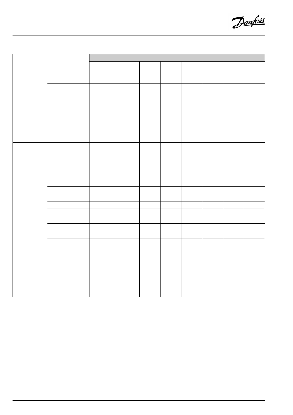
OperatingGuideECLComfort210/296/310,applicationA214/A314
Navigation,A214,applicationsA214.1,A214.2,A214.3,A214.4,A214.5andA214.6,Commoncontrollersettings,continued
Home
MENU
Keyfunctions
SystemECLversion
IDno.
NewapplicationEraseapplication
Application
FactorysettingSystemsettings
Copy
Keyoverview
Extension
Ethernet
Portalconfig
M-busconfig
EnergyMeters
Rawinputoverview
Alarm
Display
Communication
Language
60058
60059
2048
38
39
2150
2151
2050
Function
Usersettings
Gotofactory
To
Systemsettings
Usersettings
Startcopying
Codeno.
Hardware
Software
Buildno.
Serialno.
Productiondate
Tsensordefect
Backlight
Contrast
ECL485addr.
Modbusaddr.
Baud
Servicepin
Ext.reset
Language
ApplicationsA214,Commoncontrollersettings
A214.1A214.2A214.3A214.4A214.5A214.6
((((((
((((((
((((((
((((((
((((((
((((((
((((((
((((((
((((((
((((((
((((((
((((((
((((((
((((((
((((((
((((((
((((((
((((((
((((((
((((((
((((((
((((((
((((((
((((((
((((((
((((((
((((((
((((((
((((((
((((((
((((((
92|©Danfoss|2021.06
AQ146286475947en-010601
Page 93

OperatingGuideECLComfort210/296/310,applicationA214/A314
Navigation,A314,applicationsA314.1,314.2andA314.3
Home
MENU
ScheduleSelectable
Settings
Flowtemperature11008DesiredbalanceT(((
Roomlimit
DuctTlimit
Returnlimit
LimitTsafety
Compensation1
Compensation2
Controlpar.(1)
IDno.
11178
11177
11009
11182Infl.-max.((
11183
11015
11182Infl.-max.(
11183
11015
11030
11035
11036
11037
11108
11105
11107
11139
11060
11062
11063
11061
11139
11064
11066
11067
11065
11174
11184
11185
11186
11187
11189
ApplicationA314
Function
Temp.max.(((
Temp.min.(((
Deadzone((
Infl.-min.((
Adapt.time((
Infl.-min.(
Adapt.time
Limit
Infl.-max.
Infl.-min.
Adapt.time
LimitTfrost
Infl.-min.
Adapt.time
Actualcomp.T
Limit(((
Infl.-max.
Infl.-min.
Adapt.time
Actualcomp.T
Limit(((
Infl.-max.
Infl.-min.(((
Adapt.time(((
Motorpr.
Xp(((
Tn(((
Mrun(((
Nz(((
Min.act.time((
A314.1A314.2A314.3
(
(((
(((
(((
(
(((
(((
(((
(((
(((
(((
(((
(((
(((
(((
((
(
AQ146286475947en-010601
©Danfoss|2021.06|93
Page 94

OperatingGuideECLComfort210/296/310,applicationA214/A314
Navigation,A314,applicationsA314.1,A314.2andA314.3continued
Home
MENU
Settings
Controlpar.2
Fan/acc.control
Application
IDno.
12174
12184
12185
12187
12165
12167
12171
11098
11081
11104
11088
11086
11137
11089
11087
11091
11090
11077
11027
11010
11500
11021
11140
11093
10304
11082
11141
11142
Function
Motorpr.
Xp((
Tn((
Nz((
Voutmax.((
Voutmin.((
Reverseout((
Windactual(
Filterconstant(
Controlvoltage(
Fanoutputfunc.
Fancut-indelay
Fanfunction
Acc.outputfunc.
Acc.cut-indelay
Acc.timecontrol
Optionalfunction
PfrostT
RoomTdiff.
ECAaddr.
SenddesiredT
Totalstop
Comp.Tselect
Frostpr.T(
S4filter
Accum.filter
Ext.input(((
Ext.mode(((
ApplicationsA314
A314.1A314.2A314.3
((
(((
(((
(((
(((
(((
(((
(((
(((
(
((
(((
(((
(((
(
((
94|©Danfoss|2021.06
AQ146286475947en-010601
Page 95

OperatingGuideECLComfort210/296/310,applicationA214/A314
Navigation,A314,applicationsA314.1,A314.2andA314.3continued
Home
MENU
HolidaySelectable
Alarm
InfluenceoverviewDes.flowT
FrostT
LimitTfrost
Frostthermostat
Firesafety
Temp.monitor.
Alarmoverview
IDno.
11676
11656
11616
11617
11636
11637
11147
11148
11149
11150
Function
Alarmvalue
Alarmvalue
Alarmvalue
Alarmtime-out
Alarmvalue
Alarmtime-out
Upperdifference
Lowerdifference
Delay
Lowesttemp.
FrostT
LimitTfrost
Frostthermostat
Firesafety
Temp.monitor.
FlowTsensor
Returnlim.
Roomlim.
DuctTlimit
Compensation1
Compensation2
LimitTsafety
Holiday
Ext.override
ECAoverride
SCADAoffset
ApplicationsA314
A314.1A314.2A314.3
(((
(((
(((
(((
(((
(((
(((
(((
(((
(((
(((
(((
(
(
(((
(((
(((
(((
(
(((
(((
(
(((
(((
(((
((
((
((
((
((
AQ146286475947en-010601
©Danfoss|2021.06|95
Page 96

OperatingGuideECLComfort210/296/310,applicationA214/A314
Navigation,A314,applicationsA314.1,A314.2andA314.3,Commoncontrollersettings
Home
MENU
Time&Date
ScheduleSelectable
Inputoverview
Log(sensors)
Outputoverride
LogtodayOutdoorT
LogyesterdayFlowT&desired
Log2daysDuctT&desired
Log4daysRoomT&desired
IDno.
ApplicationsA314,Commoncontrollersettings
Function
Selectable
OutdoorT
CompensationT
FlowT
RoomT
DuctT
ReturnT
FrostT
AccumulatedT
Frostthermostat
Firesafety
ReturnT&limit
CompensationT
FrostT
Windspeed
M1
F1
V1
M2
P2
X3
A1
A314.1A314.2A314.3
(((
(((
(((
(((
(((
((
(
(((
(((
((
(((
(((
(((
(((
(
((
(((
(((
(((
(
(((
(((
(
((
(((
(((
(((
96|©Danfoss|2021.06
AQ146286475947en-010601
Page 97
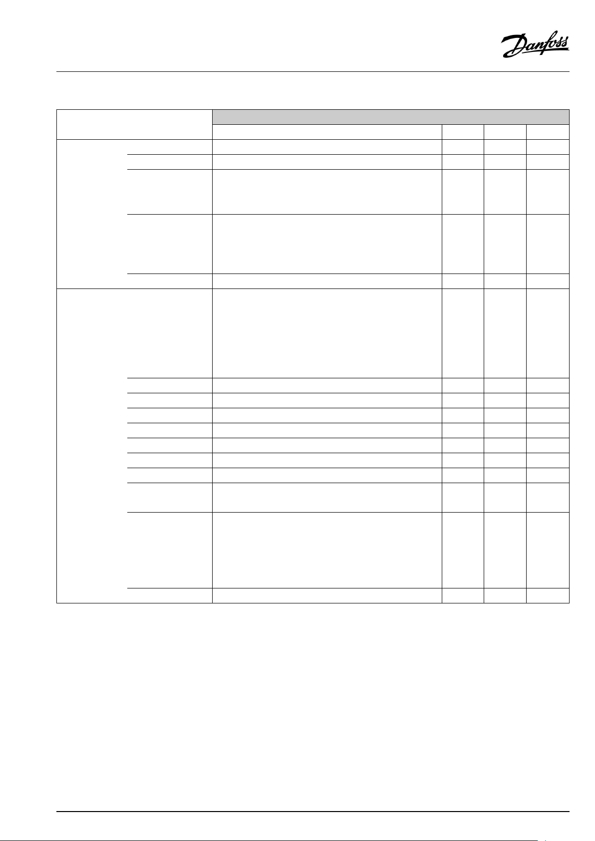
OperatingGuideECLComfort210/296/310,applicationA214/A314
Navigation,A314,applicationsA314.1,A314.2andA314.3,Commoncontrollersettings,continued
Home
MENU
Keyfunctions
SystemECLversion
ApplicationsA314,Commoncontrollersettings
IDno.
NewapplicationEraseapplication
Application
FactorysettingSystemsettings
Copy
Keyoverview
Extension
Ethernet
Portalconfig
M-busconfig
EnergyMeters
Rawinputoverview
Alarm
Display
Communication
Language
60058
60059
2048
38
39
2150
2151
2050
Function
Usersettings
Gotofactory
To
Systemsettings
Usersettings
Startcopying
Codeno.
Hardware
Software
Buildno.
Serialno.
Productiondate
Tsensordefect
Backlight
Contrast
ECL485addr.
Modbussaddr.
Baud
Servicepin
Ext.reset
Language
A314.1A314.2A314.3
(((
(((
(((
(((
(((
(((
(((
(((
(((
(((
(((
(((
(((
(((
(((
(((
(((
(((
(((
(((
(((
(((
(((
(((
(((
(((
(((
(((
(((
(((
(((
AQ146286475947en-010601
©Danfoss|2021.06|97
Page 98

OperatingGuideECLComfort210/296/310,applicationA214/A314
Navigation,A314,applicationsA314.4,A314.5,A314.6,A314.7andA314.9,circuit1
Home
MENU
ScheduleSelectable
Settings
Inlettemperature
Roomlimit
Returnlimit
LimitTsafety
Compensation1
Compensation2
Controlpar.(1)
IDno.
11018Des.Tcomfort(((((
11019
11178
11177
11009
11182Infl.-max.(((((
11183
11015
11030
11035
11036
11037
11108
11105
11107
11139
11060
11062
11063
11061
11139
11064
11066
11067
11065
11174
11184
11185
11186
11187
11189
Applications314
Function
Des.Tsaving(((((
Temp.max.(((((
Temp.min.
Deadzone
Infl.-min.(((((
Adapt.time(((((
Limit
Infl.-max.
Infl.-min.
Adapt.time
LimitTfrost
Infl.-min.
Adapt.time
Actualcomp.T
Limit(((((
Infl.-max.
Infl.-min.
Adapt.time
Actualcomp.T
Limit(((((
Infl.-max.
Infl.-min.
Adapt.time
Motorpr.
Xp(((((
Tn(((((
Mrun(((((
Nz(((((
Min.act.time((((
A314.4A314.5A314.6A314.7A314.9
(((
(
(((((
(((((
(((((
((((
(((((
(((((
(((((
(((((
(((((
(((((
(((((
(((((
(((((
(((((
(((((
(((((
((
(
(
(
98|©Danfoss|2021.06
AQ146286475947en-010601
Page 99

OperatingGuideECLComfort210/296/310,applicationA214/A314
Navigation,A314,applicationsA314.4,A314.5,A314.6,A314.7andA314.9,circuit1,continued
Home
MENU
Settings
Controlpar.2
Fan/acc.control
Application
IDno.
12368
12369
12184
12185
12187
12165
12167
11088
11086
11137
11089
11087
11091
11010
11021
11093
11140
11368
11369
11179
11082
11141
11142
Function
1.steplevel(
2.steplevel(
Xp(((((
Tn(((((
Nz
Voutmax.
Voutmin.
Fanoutputfunc.(((((
Fancut-indelay(((((
Fanfunction(((((
Acc.outputfunc.
Acc.cut-indelay
Acc.timecontrol
ECAaddr.
Totalstop
Frostpr.T(((((
Comp.Tselect
1.steplevel
2.steplevel
Summer,cut-out
Accum.filter
Ext.input(((((
Ext.mode
Applications,A314
A314.4A314.5A314.6A314.7A314.9
(((
(((
(((
(((((
(((((
(((((
(((((
(((((
(((((
((((
((((
((
((
(((((
((
((
((
AQ146286475947en-010601
©Danfoss|2021.06|99
Page 100

OperatingGuideECLComfort210/296/310,applicationA214/A314
Navigation,A314,applicationsA314.4,A314.5,A314.6,A314.7andA314.9,circuit1,continued
Home
MENU
HolidaySelectable
Alarm
FrostT
LimitTfrost
Frostthermostat
Firesafety
DigitalS9
DigitalS10
Inletpressure
Outletpressure
Airquality
Temp.monitor.
Heatrecovery
IDno.
11676
11656
11616
11617
11636
11637
10656
10657
12390
10696
10697
13614
13615
13617
13390
14614
14615
14617
14390
13614
13615
13617
11147
11148
11149
11150
12615
12617
ApplicationsA314
Function
Alarmvalue
Alarmvalue
Alarmvalue
Alarmtime-out
Alarmvalue
Alarmtime-out
Alarmvalue
Alarmtime-out
Clearalarm
Alarmvalue
Alarmtime-out
Alarmhigh
Alarmlow
Alarmtime-out
Clearalarm
Alarmhigh
Alarmlow
Alarmtime-out
Clearalarm
Alarmhigh
Alarmlow
Alarmtime-out
Upperdifference
Lowerdifference
Delay
Lowesttemp.
Alarmlow
Alarmtime-out(
A314.4A314.5A314.6A314.7A314.9
(((((
(((((
(((((
(((((
(((((
(((((
(((((
(((((
(((((
(((((
(((((
(((((
(((((
(((((
(((((
((
((
((
((
((
(((
(((
(((
(((((
(((((
(((((
(((((
((((
(((
100|©Danfoss|2021.06
AQ146286475947en-010601
 Loading...