

Page 1
MAKING MODERN LIVING POSSIBLE
Technical Information
Concrete Pumps
Series 90
powersolutions.danfoss.com
Page 2

Technical Information Series 90 Concrete Pumps
Revision history Table of revisions
Date Changed Rev
February 2016 minor edits - new installation drawings 0202
June 2014 Converted to Danfoss layout – DITA CMS BA
February 2014 First Edition AA
2 BC00000360en-US • Rev 0202 • February 2016
Page 3

Technical Information
Contents
General Description
Technical specifications
Operating Parameters
System Design Parameters
Master Model Code
Control Options
Features and Options
Installation Drawings
Series 90 Concrete Pumps
Series 90 Concrete Pumps.............................................................................................................................................................4
General Specifications.................................................................................................................................................................... 5
Features and Options......................................................................................................................................................................5
Operating Parameters.....................................................................................................................................................................6
Fluid Specifications..........................................................................................................................................................................6
Overview..............................................................................................................................................................................................7
Input Speed........................................................................................................................................................................................ 7
System Pressure................................................................................................................................................................................7
Servo Pressure................................................................................................................................................................................... 7
Charge Pressure................................................................................................................................................................................ 8
Case Pressure..................................................................................................................................................................................... 8
External Shaft Seal Pressure..........................................................................................................................................................8
Temperature and Viscosity........................................................................................................................................................... 9
Filtration System.............................................................................................................................................................................10
Filtration Options...........................................................................................................................................................................10
Suction filtration – Option S................................................................................................................................................. 10
Fluid Selection.................................................................................................................................................................................10
Reservoir............................................................................................................................................................................................11
Case Drain.........................................................................................................................................................................................11
Pump Life..........................................................................................................................................................................................11
Understanding and Minimizing System Noise....................................................................................................................11
Sizing Equations............................................................................................................................................................................. 12
Mounting Flange Loads...............................................................................................................................................................12
Accumulator.................................................................................................................................................................................... 13
High Pressure Signal Output Port X10................................................................................................................................... 13
Master Model Code....................................................................................................................................................................... 14
Hydraulic Displacement Control (HDC), Option HD; H9..................................................................................................17
Operation.....................................................................................................................................................................................17
Features and Benefits..............................................................................................................................................................17
Pump output flow direction vs. control pressure.........................................................................................................18
Multi-Function Valves...................................................................................................................................................................19
Overpressure protection........................................................................................................................................................19
Bypass Function........................................................................................................................................................................ 19
Auxiliary Mounting Pads............................................................................................................................................................. 20
Mating pump requirements................................................................................................................................................. 20
Displacement Limiter................................................................................................................................................................... 21
Shaft Torque.....................................................................................................................................................................................22
Shaft Availibility and Torque Ratings......................................................................................................................................22
Charge Pump...................................................................................................................................................................................23
Charge pump sizing/selection.............................................................................................................................................23
Charge pump flow and power curves...............................................................................................................................24
Loop Flushing Valve......................................................................................................................................................................25
Frame Size 130................................................................................................................................................................................ 27
Frame Size 180................................................................................................................................................................................ 29
BC00000360en-US • Rev 0202 • February 2016 3
Page 4
M3
S
X2
X1
P108958
TA
M5
M4
TB
S (B)
S (A)
P
M10
L1
L2
CW
2
1
flow out
M2
X9 (M22)
X9 (3/4)
X8 (M22)
X8 (3/4)
M1
X 10
M12
B
T
A
M3
S
X2 X1
TA
M5
M4
TB
S (B)
S (A)
P
M10
L1
L2
CW
2
1
M2
X9 (M22)
X9 (3/4)
X8 (M22)
X8 (3/4)
M1
X 10
M12
B
T
A
X12
X11
A
N
X3(M11)
N
X12
X11
flow out
A
X3(M11)
Technical Information Series 90 Concrete Pumps
General Description
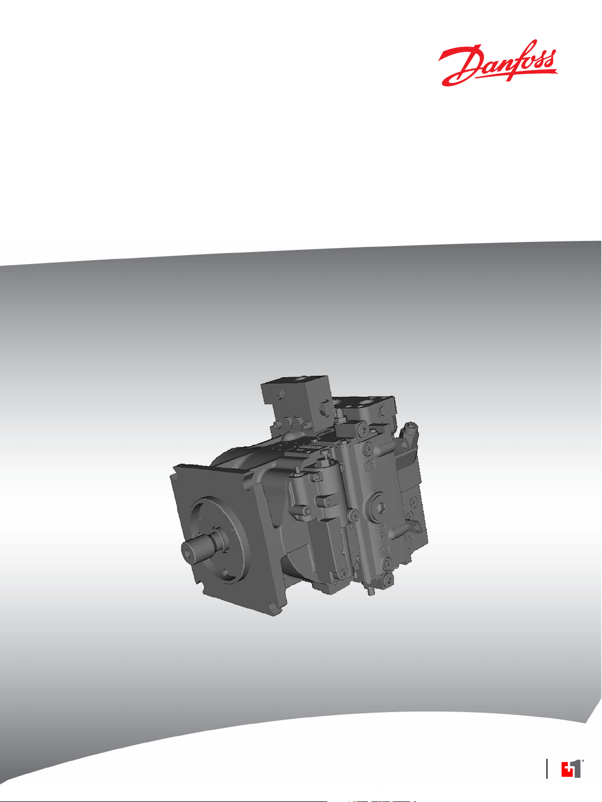
Series 90 Concrete Pumps
The S90 concrete pumps are designed for 2 cylinder concrete pump applications. This Technical
Infomation only describes concrete pump specific information - General information about Series 90
pumps can be found in Series 90 Axial Piston Pumps Technical Information 520L0603.
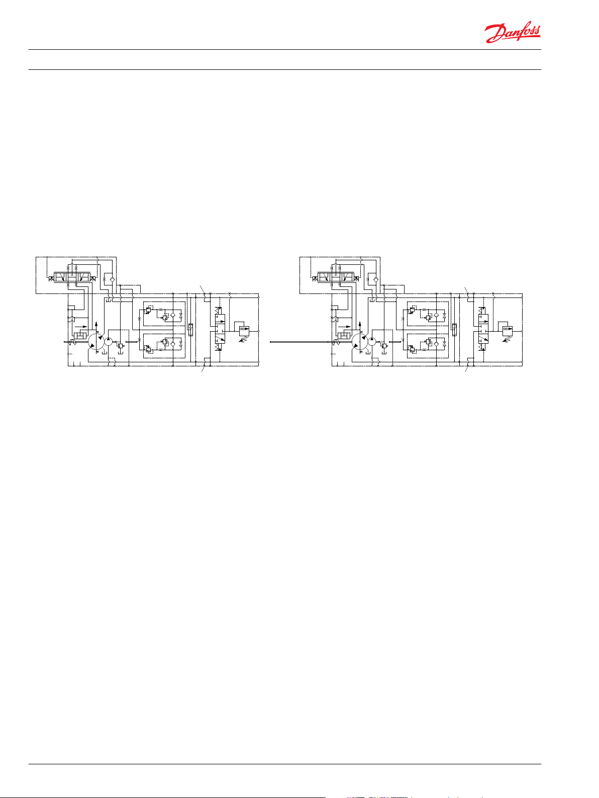
The concrete pump system can be built up as Series 90 single or tandem pumps. Each pump can be
equipped with a loop flushing valve (LFV).
System Schematic
4 BC00000360en-US • Rev 0202 • February 2016
Page 5
Technical Information Series 90 Concrete Pumps
Technical specifications
General Specifications
Design Axial piston pump of cradle swashplate design with variable displacement
Direction of rotation Clockwise, counterclockwise
Pipe connections Main pressure ports: ISO split flange boss
Remaining ports: SAE straight thread O-ring boss
Recommended installation position Pump installation position is discretionary, however the recommended control position is on the top
or at the side, with the top position preferred.
Vertical input shaft installation is acceptable.
If input shaft is at the top 1 bar case pressure must be maintained during operation.
The pump housing must be filled with hydraulic fluid under all conditions; including after a long
period of shutdown. Before operating the machine, ensure the pump housing and case drain lines are
free of air.
Recommended mounting for a multiple pump stack is to arrange the highest power flow towards the
input source.
Consult Danfoss for nonconformance to these guidelines.
Auxiliary cavity pressure Will be inlet pressure with internal charge pump. For reference see Operating Parameters on page 6.
Will be case pressure with external charge supply.
Please verify mating pump shaft seal capability.
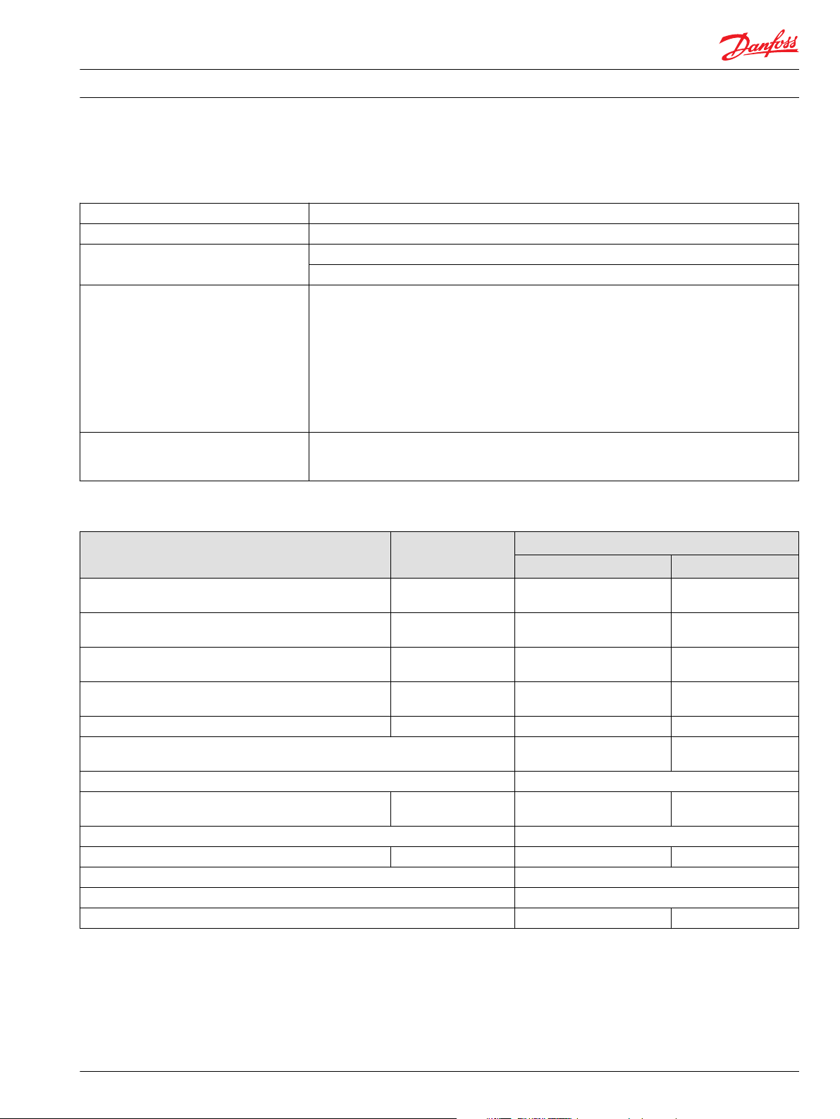
Features and Options
Feature Unit Frame
130 180
Displacement cm³/rev.
[in³]/rev.
Flow at rated speed (theoretical) l/min.
[US gal/min.]
Torque at maximum displacement (theoretical) N•m/bar
[lbf•in/1000 psi]
Mass moment of inertia of rotating components kg•m²
[slug•ft²]
Weight (with control opt. MA) kg [lb] 88 [195] 136 [300]
Mounting (per ISO 3019-1) Flange
Rotation
Main ports: 4-bolt split-flange
(per SAE J518 code 62)
Main port configuration Twin port
Case drain ports (SAE O-ring boss) UNF thread (in.) 1.3125–12 1.625–12
Other ports SAE O-ring boss
Shafts Splined, and tapered shafts available
Auxiliary mounting SAE-A, B, C, D SAE-A, B, C, D, E
mm
[in]
130
[7.93]
403
[106]
2.07
[1260]
0.023
[0.0170]
152-4 (SAE D)
31.75
[1.25]
180
[10.98]
468
[124]
2.87
[1750]
0.0380
[0.0280]
Flange
165-4 (SAE E)
31.75
[1.25]
BC00000360en-US • Rev 0202 • February 2016 5
Page 6
Technical Information Series 90 Concrete Pumps
Technical specifications
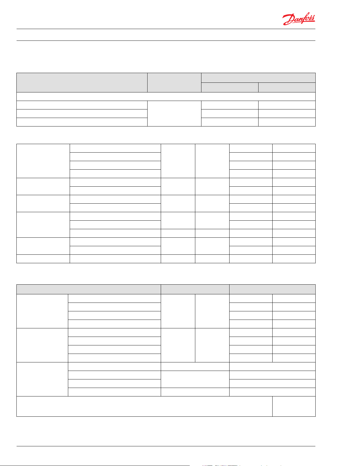
Operating Parameters
Parameter Unit Frame
130 180
Input speed
Minimum min-1(rpm) 500 500
Rated Speed 3100 2600
Maximum 3400 2850
Operating parameters
System pressure Maximum working pressure bar [psi] 450 [6525]
Maximum pressure 480 [6960]
Maximum low loop 45 [650]
Minimum low loop pressure 10 [145]
Charge pressure Minimum bar [psi] 18 [261]
Maximum 34 [493]
Control pressure Minimum (at corner power for HDC) bar [psi] 14 [203]
Maximum 40 [580]
Charge pump inlet
pressure
Case pressure Rated bar [psi] 3.0 [44]
Lip seal external pressure Maximum bar [psi] 0.4 [5.8]
Rated bar (absolute) [in Hg vacuum] 0.7 [9]
Minimum (cold start) 0.2 [24]
Maximum bar [psi] 4.0 [58]
Maximum 12 [174]
Fluid Specifications
Feature Unit
Viscosity Intermittent
Minimum 7 [49]
Recommended range 12-80 [66-370]
Maximum 1600 [7500]
Temperature
range 2)
Minimum (cold start) 3) °C [°F] -40 [-40]
Recommended range 60-85 [140-185]
Rated 104 [220]
Maximum intermittent
Filtration
(recommended
minimum)
Cleanliness per ISO 4406-1999 22/18/13
Efficiency (charge pressure filtration) β-ratio β
Efficiency (suction and return line filtration) β
Recommended inlet screen mesh size µm 100 – 125
1)
Intermittent = Short term t < 1min per incident and not exceeding 2 % of duty cycle based load-life
2)
At the hottest point, normally case drain port
3)
Cold start = Short term t < 3min, p ≤ 50 bar [725 psi], n ≤ 1000 min-1(rpm)
1)
1)
mm2/s [SUS] 5 [42]
115 [240]
= 75 (β10 ≥ 10)
15-20
= 75 (β10 ≥ 2)
35-45
T000 129E
6 BC00000360en-US • Rev 0202 • February 2016
Page 7

Technical Information
Operating Parameters
Overview
Input Speed
Series 90 Concrete Pumps
This section defines the operating parameters and limitations for Series 90 pumps with regard to input
speeds and pressures. For actual parameters, refer to the operating parameters for each displacement.
Minimum speed is the lowest input speed recommended during engine idle condition. Operating below
minimum speed limits the pump's ability to maintain adequate flow for lubrication and power
transmission.
Rated speed is the highest input speed recommended at full power condition. Operating at or below
this speed should yield satisfactory product life.
Maximum speed is the highest operating speed permitted. Exceeding maximum speed reduces product
life and can cause loss of hydrostatic power and braking capacity. Never exceed the maximum speed
limit under any operating conditions.
Operating conditions between Rated speed and Maximum speed should be restricted to less than full
power and to limited periods of time.
For more information consult Pressure and Speed Limits, BLN-9884, when determining speed limits for a
particular application.
System Pressure
Servo Pressure
System pressure is the differential pressure between high pressure system ports. It is the dominant
operating variable affecting hydraulic unit life. High system pressure, which results from high load,
reduces expected life. Hydraulic unit life depends on the speed and normal operating, or weighted
average, pressure that can only be determined from a duty cycle analysis.
Application pressure is the high pressure relief or pressure limiter setting normally defined within the
order code of the pump. This is the applied system pressure at which the drive-line generates the
maximum calculated pull or torque in the application.
Maximum working pressure is the highest recommended Application pressure. Maximum working
pressure is not intended to be a continuous pressure. Propel systems with application pressures at, or
below, this pressure should yield satisfactory unit life given proper component sizing.
Maximum pressure is the highest allowable Application pressure under any circumstance. Application
pressures above maximum working Pressure will only be considered with duty cycle analysis and factory
approval.
Pressure spikes are normal and must be considered when reviewing maximum working pressure.
Minimum low loop pressure must be maintained under all operating conditions to avoid cavitation.
All pressure limits are differential pressures referenced to low loop (charge) pressure. Subtract low loop
pressure from gauge readings to compute the differential.
Servo pressure is the pressure in the Servo-system needed to position and hold the pump on stroke. It
depends on system pressure and speed.
At minimum servo pressure the pump will run at reduced stroke depending on speed and pressure.
Minimum servo pressure at corner power holds the pump on full stroke at max speed and max pressure.
Maximum servo pressure is the highest pressure typically given by the charge pressure setting.
BC00000360en-US • Rev 0202 • February 2016 7
Page 8

C
C
Technical Information
Operating Parameters
Charge Pressure
Series 90 Concrete Pumps
An internal charge relief valve regulates charge pressure. Charge pressure supplies the control with
pressure to operate the swashplate and to maintain a minimum pressure in the low side of the
transmission loop. The charge pressure setting listed in the order code is the set pressure of the charge
relief valve with the pump in neutral, operating at 1800 min-1 [rpm], and with a fluid viscosity of 32 mm2/s
[150 SUS]. Pumps configured with no charge pump (external charge supply) are set with a charge flow of
30 l/min. [7.93 US gal/min.] and a fluid viscosity of 32 mm2/s [150 SUS].
The charge pressure setting is referenced to case pressure. Charge pressure is the differential pressure
above case pressure.
Minimum charge pressure is the lowest pressure allowed to maintain a safe working condition in the
low side of the loop. Minimum control pressure requirements are a function of speed, pressure, and
swashplate angle, and may be higher than the minimum
charge pressure shown in the Operating parameters tables.
Maximum charge pressure is the highest charge pressure allowed by the charge relief adjustment, and
which provides normal component life. Elevated charge pressure can be used as a secondary means to
reduce the swashplate response time.
At normal operating temperature charge inlet pressure must not fall below rated charge inlet pressure
(vacuum).
Minimum charge inlet pressure is only allowed at cold start conditions. In some applications it is
recommended to warm up the fluid (e.g. in the tank) before starting the engine and then run the engine
at limited speed.
Maximum charge pump inlet pressure may be applied continuously.
Case Pressure
External Shaft Seal Pressure
Under normal operating conditions, the rated case pressure must not be exceeded. During cold start
case pressure must be kept below maximum intermittent case pressure. Size drain plumbing accordingly.
Auxiliary Pad Mounted Pumps. The auxiliary pad cavity of S90 pumps configured without integral
charge pumps is referenced to case pressure. Units with integral charge pumps have auxiliary mounting
pad cavities referenced to charge inlet (vacuum).
Caution
Possible component damage or leakage
Operation with case pressure in excess of stated limits may damage seals, gaskets, and/or housings,
causing external leakage. Performance may also be affected since charge and system pressure are
additive to case pressure.
In certain applications the input shaft seal may be exposed to external pressure. In order to prevent
damage to the shaft seal the maximum differential pressure from external sources must not exceed 0.4
bar (5.8 psi) over pump case pressure. The case pressure limits of the pump must also be followed to
ensure the shaft seal is not damaged.
Caution
Regardless of the differential pressure across the shaft seal, the shaft seal has been known to pump oil
from the external source (e. g. gear box) into the pump case.
8 BC00000360en-US • Rev 0202 • February 2016
Page 9

Technical Information Series 90 Concrete Pumps
Operating Parameters
Temperature and Viscosity
Temperature
The high temperature limits apply at the hottest point in the transmission, which is normally the motor
case drain. The system should generally be run at or below the quoted rated temperature.
The maximum intermittent temperature is based on material properties and should never be
exceeded.
Cold oil will generally not affect the durability of the transmission components, but it may affect the
ability of oil to flow and transmit power; therefore temperatures should remain 16 °C [30 °F] above the
pour point of the hydraulic fluid.
The minimum temperature relates to the physical properties of component materials.
Size heat exchangers to keep the fluid within these limits. Danfoss recommends testing to verify that
these temperature limits are not exceeded.
Viscosity
For maximum efficiency and bearing life, ensure the fluid viscosity remains in the recommended range.
The minimum viscosity should be encountered only during brief occasions of maximum ambient
temperature and severe duty cycle operation.
The maximum viscosity should be encountered only at cold start.
BC00000360en-US • Rev 0202 • February 2016 9
Page 10
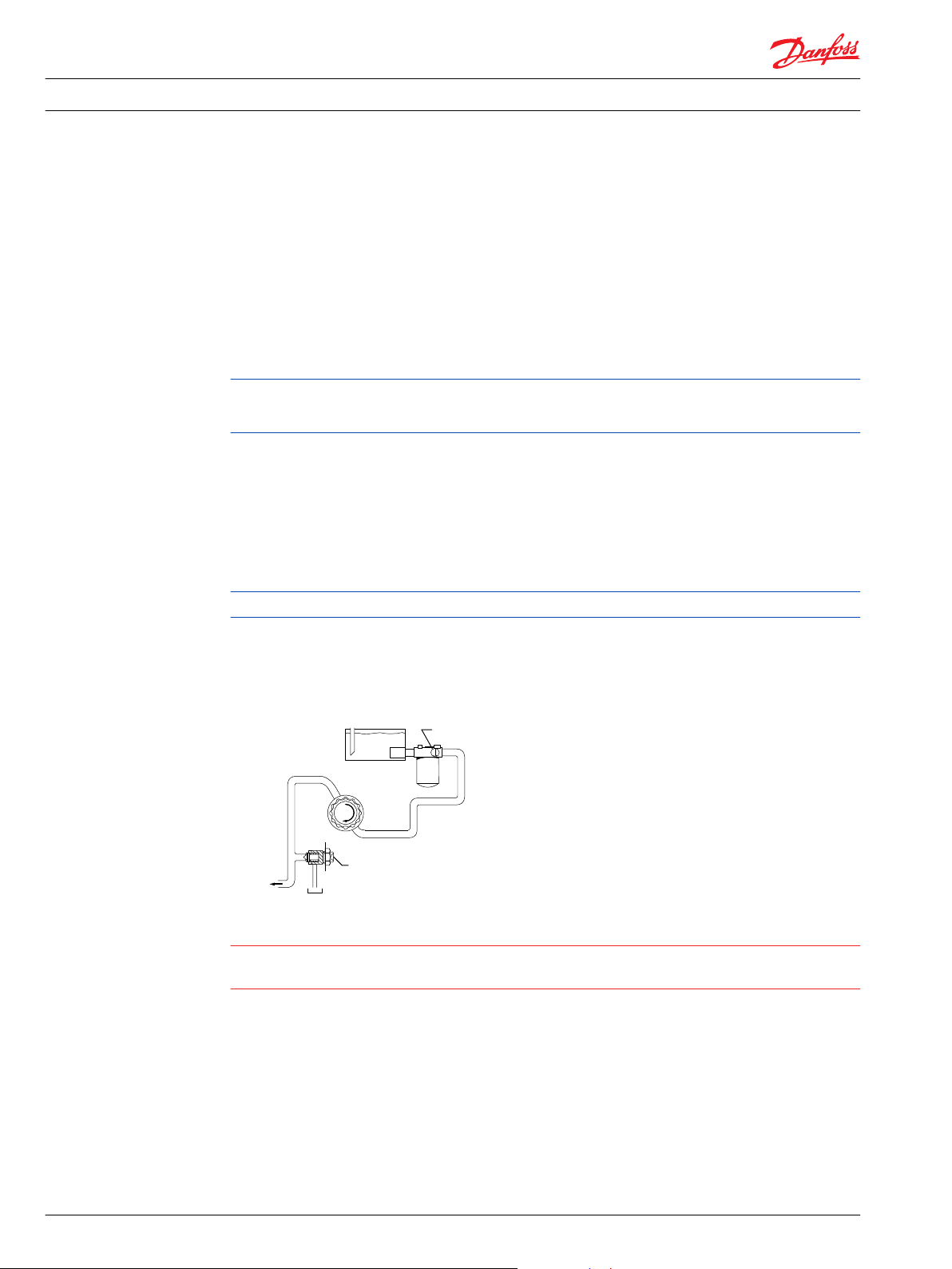
Charge pump
Filter
Hydraulic fluid reservoir
Adjustable
charge pressure relief valve
To pump case
To low
loop and
control
Manometer
P102 003E
C
Technical Information
System Design Parameters
Filtration System
Filtration Options
Series 90 Concrete Pumps
To prevent premature wear, ensure only clean fluid enters the hydrostatic transmission circuit. A filter
capable of controlling the fluid cleanliness to ISO 4406 class 22/18/13 (SAE J1165) or better, under normal
operating conditions, is recommended.
These cleanliness levels can not be applied for hydraulic fluid residing in the component housing/case or
any other cavity after transport.
Filter efficiency can be measured with a Beta ratio (βX). For suction filtration, a filter with a β-ratio within
the range of β
Filter βx-ratio is a measure of filter efficiency defined by ISO 4572. It is defined as the ratio of the number
of particles greater than a given diameter (“x” in microns) upstream of the filter to the number of these
particles downstream of the filter.
Because each system is unique, only a thorough testing and evaluation program can fully validate the
filtration system. Please see Design Guidelines for Hydraulic Fluid Cleanliness Technical Information,
520L0467 for more information.
= 75 (β10 ≥ 2) or better has been found to be satisfactory.
35-45
Fluid Selection
Suction filtration – Option S
Suction filtration is the only option available for concrete pumps.
The suction filter is placed in the circuit between the reservoir and the inlet to the charge pump, as
shown below.
The use of a filter contamination monitor is recommended.
Suction filtration
Caution
Clogged filters can cause cavitation, which damages the charge pump. We recommend a filter bypass
with a filter bypass sensor to prevent damage due to blocked suction filters.
Ratings and performance data are based on operating with hydraulic fluids containing oxidation, rust
and foam inhibitors. These fluids must possess good thermal and hydrolytic stability to prevent wear,
erosion, and corrosion of pump components.
Never mix hydraulic fluids of different types.
10 BC00000360en-US • Rev 0202 • February 2016
Page 11

Technical Information
System Design Parameters
Reservoir
Case Drain
Series 90 Concrete Pumps
The hydrostatic system reservoir should accommodate maximum volume changes during all system
operating modes and promote de-aeration of the fluid as it passes through the tank. A suggested
minimum total reservoir volume is 5⁄8 of the maximum charge pump flow per minute with a minimum
fluid volume equal to ½ of the maximum charge pump flow per minute. This allows 30 seconds fluid
dwell for removing entrained air at the maximum return flow. This is usually adequate to allow for a
closed reservoir (no breather) in most applications.
Locate the reservoir outlet (charge pump inlet) above the bottom of the reservoir to take advantage of
gravity separation and prevent large foreign particles from entering the charge inlet line. A 100-125 μm
screen over the outlet port is recommended. Position the reservoir inlet (fluid return) to discharge below
the normal fluid level, toward the interior of the tank. A baffle (or baffles) will further promote de-aeration
and reduce surging of the fluid.
All single S90 pumps are equipped with multiple drain ports. Port selection and case drain routing must
enable the pump housing to maintain a volume of oil not less than half full and normal operating case
pressure limits of the unit are maintained. Case drain routing and design must consider unit case pressure
ratings.
A case drain line must be connected to one of the case outlets to return internal leakage to the system
reservoir.
Do not over torque the fitting on case drain port L2 (located on the side cover). The proper torque is 100
N•m [74 lbf•ft] maximum. Over torquing the fitting may change the neutral position of the swashplate.
Pump Life
Pump life depends on several factors, such as speed, pressure, and swashplate angle. For detailed
product life calculation, please contact your Danfoss representative.
Understanding and Minimizing System Noise
Noise is transmitted in fluid power systems in two ways: as fluid borne noise, and structure borne noise.
Fluid-borne noise (pressure ripple or pulsation) is created as pumping elements discharge oil into the
pump outlet. It is affected by the compressibility of the oil, and the pump's ability to transition pumping
elements from high to low pressure. Pulsations travel through the hydraulic lines at the speed of sound
(about 1400 m/s [4600 ft/sec] in oil) until there is a change (such as an elbow) in the line. Thus, amplitude
varies with overall line length and position.
Structure born noise is transmitted wherever the pump casing connects to the rest of the system. The
way system components respond to excitation depends on their size, form, material, and mounting.
System lines and pump mounting can amplify pump noise.
Follow these suggestions to help minimize noise in your application:
Use flexible hoses.
•
Limit system line length.
•
If possible, optimize system line position to minimize noise.
•
If you must use steel plumbing, clamp the lines.
•
If you add additional support, use rubber mounts.
•
Test for resonants in the operating range; if possible avoid them.
•
BC00000360en-US • Rev 0202 • February 2016 11
Page 12
Output f ow Q = (l/min..)
Inp ut torque M = (N•m)
Inp ut power P = = (kW)
SI units Vg= Displacement per revolution
(cm3/rev)
∆p = pO- pi(system pressure)
(bar)
n = Speed (min-1(rpm))
ηv= Volumetric eff cien cy
ηm= Mechanical eff cien cy
ηt= Overall eff ciency (ηv• ηm)
Vg• n • η
v
1000
Vg• ∆p
20 • π • η
m
Q •∆p
600 • η
t
M • n • π
30 000
g
= Displacement per revolution
(in3/rev)
∆p = pO- pi(system pressure)
(psi)
n = Speed (min-1(rpm))
ηv= Volumetric eff cien cy
ηm= Mechanical eff cien cy
ηt= Overall eff ciency (ηv• ηm)
Output f ow Q = (US gal/min..)
Inp ut torque M = (lbf•in)
Inp ut power P = = (hp)
Vg• n • η
v
231
Vg• ∆p
2 • π • η
m
Q •∆p
1714 • η
t
M • n • π
198 000
First stageSecond stage
Third
stage
P108 511E
L1
L2
L3
F2 F1
F3
Technical Information
System Design Parameters
Sizing Equations
Series 90 Concrete Pumps
The following equations are helpful when sizing hydraulic pumps. Generally, the sizing process is
initiated by an evaluation of the machine system to determine the required motor speed and torque to
perform the necessary work function. Refer to Selection of drive line components, BLN-9885, for a more
complete description of hydrostatic drive line sizing. First, the motor is sized to transmit the maximum
required torque. The pump is then selected as a flow source to achieve the maximum motor speed.
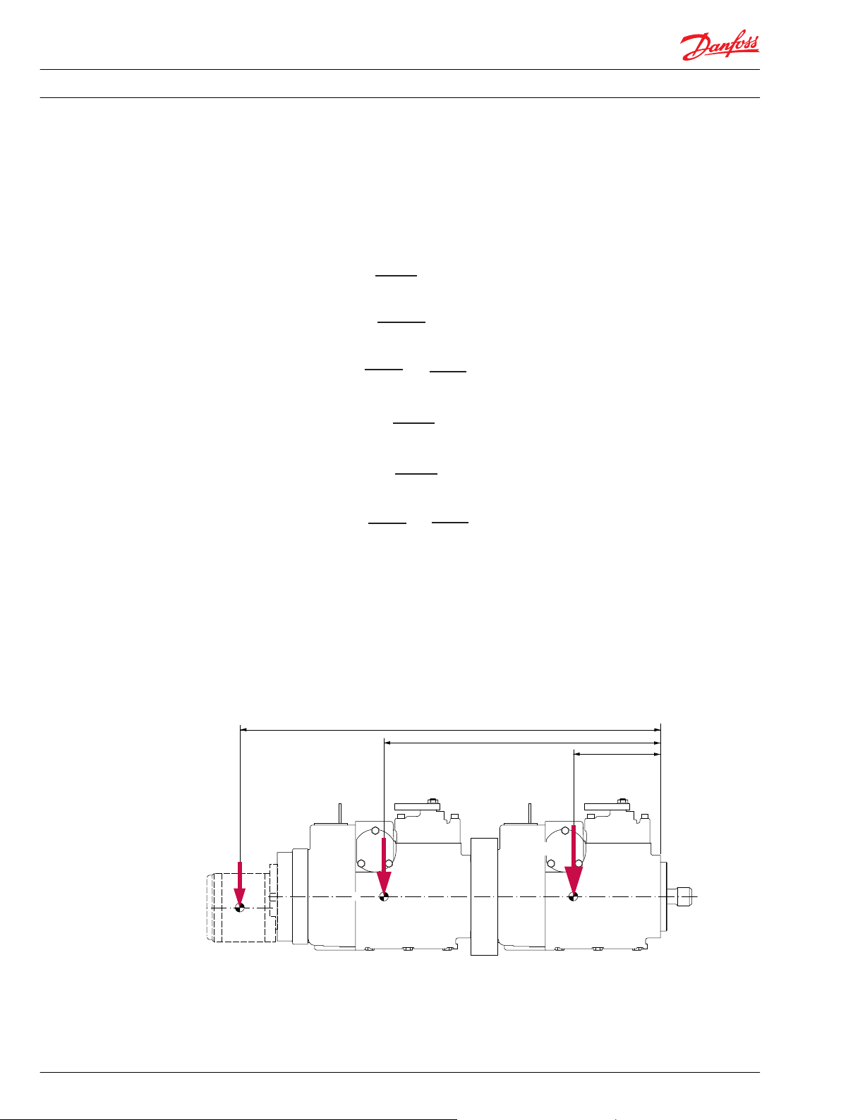
Mounting Flange Loads
Adding tandem mounted auxiliary pumps and/or subjecting pumps to high shock loads may result in
excessive loading of the mounting flange.
Applications which experience extreme resonant vibrations or shock may require additional pump
support. The overhung load moment for multiple pump mounting may be estimated using the formula
below.
Overhung load example
12 BC00000360en-US • Rev 0202 • February 2016
Estimated maximum and rated acceleration factors for some typical applications are shown in the table
below.
Page 13

R
= g • GR(W1L1+ W2L2+ ... + WnLn)
S
= g • GS(W1L1+ W2L2+ ... + WnLn)
R
= Rated load moment N•m
S
= Shock load moment N•m
2
R
= Calculation factor for rated (vibratory) acceleration (G’s)*
S
= Calculation factor for maximum shock acceleration (G’s)*
MR= GR(W1L1+ W2L2+ ... + WnLn)
MS= GS(W1L1+ W2L2+ ... + WnLn)
Based on US units
W = Weight of pump [lb]
L = Distance from mounting f ange [in]
to pump center of gravity
Where:
MR= Rated load moment N•m
MS= Shock load moment N•m
HP A
HP B
Port X10: HP Out
P108721
Technical Information
System Design Parameters
Series 90 Concrete Pumps
Allowable overhung load moment values are shown in the following table.
Allowable overhung load moments
Frame size Rated moment (MR) Shock load moment (MS)
N•m lbf•in N•m lbf•in
130 3160 28 000 10 730 95 000
180 6070 54 000 20 600 182 000
Accumulator
Typical for concrete pump systems is a significant pressure drop on the low pressure side. The gage port
M3 can be used to conncet an accumulator on to the system. The accumulator has to be connected to
port M3. The volume size of the accumulator has to be at least 1.6 liters or larger. The preliminary charge
pressure is at least 2 bar.
High Pressure Signal Output Port X10
This port provides a high pressure signal from side A or B of the working loop controlled by a 2-wayshuttle valve within the endcap.
This port can be used for a torque limiter control.
BC00000360en-US • Rev 0202 • February 2016 13
Page 14
M J G F
L
T
H Y Z
K
S90
Size
R
P
N
W
Technical Information Series 90 Concrete Pumps
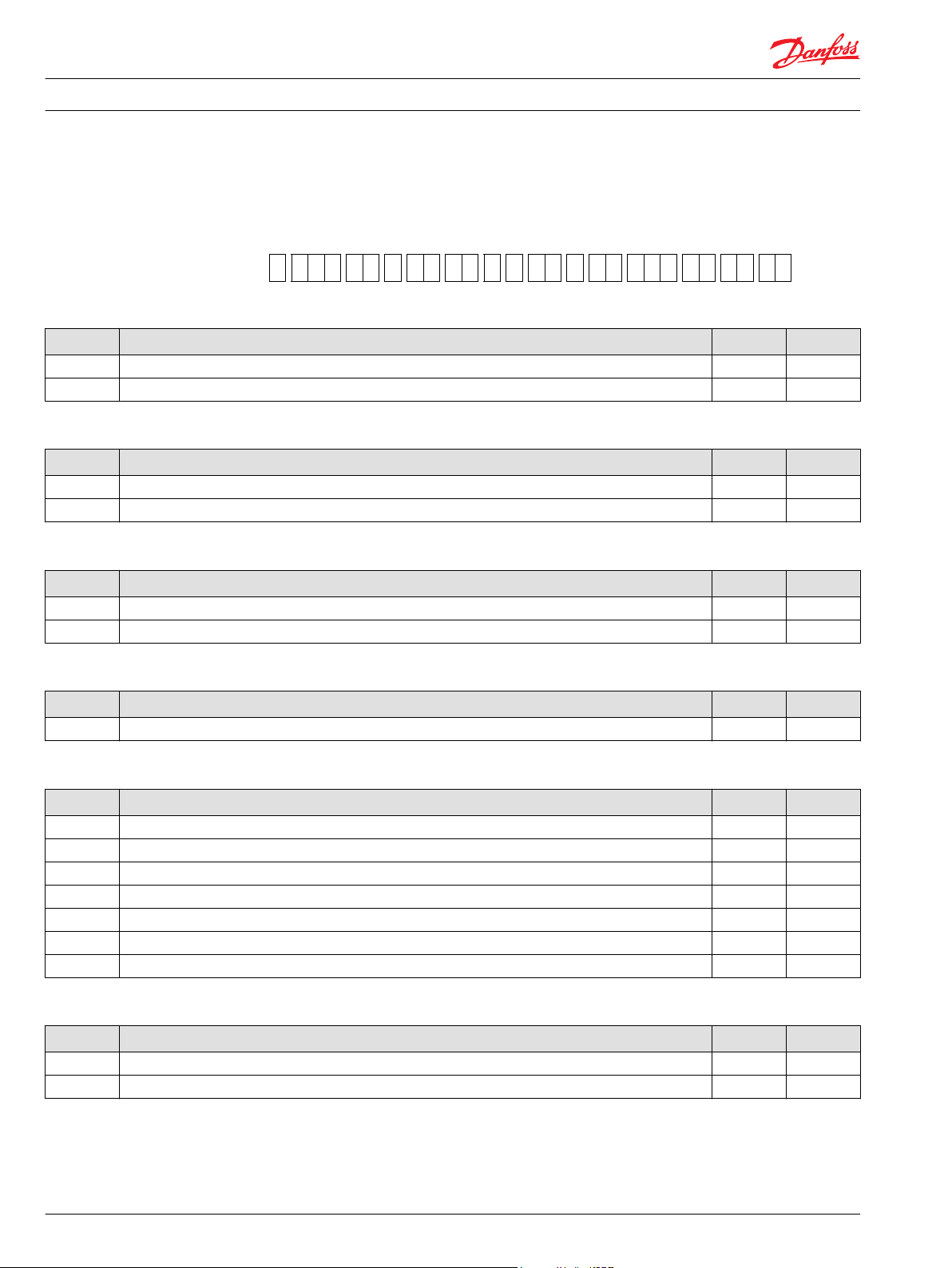
Master Model Code
Master Model Code
R - Type and Rotation
Code Description 130 180
R Right Hand [CW] O O
L Left Hand [CCW] O O
Size
Code Description 130 180
130 130 cc [7.93 in³] max. displacement per revolution O
180 180 cc [10.98 in³] max. displacement per revolution O
M - Controls
Code Description 130 180
HD HDC, standard porting, 6 - 18 bar (88 - 264 PSI), UNF thread ports O O
H9 Standard porting, 6.0-18.0 bar (88-264 psi), metric thread ports O
P - High Pressure Regulation
Code Description 130 180
D high pressure relief valves for port A and B (240-350 bar) O O
J - Auxiliary Mounting Pad
Code Description 130 180
AB SAE-A with sealed cover, 9 teeth coupling O O
BB SAE-BB with sealed cover, 15 teeth coupling O O
BC SAE-B with sealed cover, 13 teeth coupling O O
CD SAE-C with sealed cover, 4 bolt adapter, 14 teeth coupling, (2) ½-13 UNC O O
DE SAE-D with sealed cover, 13 teeth coupling O O
EF SAE-E with sealed cover, 13 teeth coupling O
NN no auxiliary mounting pad O O
G - Endcap Ports
Code Description 130 180
8C twin ports with high pressure shuttle valve, HD measurement port, UNF thread ports, loop flushing valve O O
9C twin ports with high pressure shuttle valve, HD measurement port, metric thread ports, loop flushing valve O
14 BC00000360en-US • Rev 0202 • February 2016
Page 15

Technical Information Series 90 Concrete Pumps
Master Model Code
N - Filtration
Code Description 130 180
S suction filtration O O
K suction filtration with metric port O
F - Displacement Limitation
Code Description 130 180
C no limiters, only for 180 cc O
M limitation both sides, only for 180 cc O
3 no limiters O
4 limitation both sides O
E limitation both sides, spec. servo cylinder with gage ports O O
L - Shaft Options
Code Description 130 180
C8 splined shaft, 27 teeth, pitch = 16 / 32 O O
F1 splined shaft, 13 teeth, pitch = 8 / 16 O O
D5 Splined shaft, W50x2x30x24x9g per DIN 5480 O
H - Charging System
Code Description 130 180
F nominal flow = 26 cc / rev O
H nominal flow = 34 cc / rev O O
J nominal flow = 47 cc / rev O
T - Control Orifice Options
Code Description
HDC
inlet P drain TA drain TB servo A servo B 130 180
00 n/o 1.3 1.3 n/o n/o O O
W - Special Hardware Features
Code Description 130 180
GBA CP15 +0,5° valve plate O
NNN 180cc: CP15 +0,5° valve plate O
250cc: CP15 +0,5° valve plate , nested T- bar springs
GCE CP15 +1,5° valve plate, metric ports, special plate retainer O
GCF CP15 +1,5° valve plate, metric ports O
BC00000360en-US • Rev 0202 • February 2016 15
Page 16

Technical Information Series 90 Concrete Pumps
Master Model Code
Y - High Pressure Setting A
Code Description 130 180
32 320 bar O O
35 350 bar O O
Z - High Pressure Setting B
Code Description 130 180
32 320 bar O O
35 350 bar O O
K - Charge Pressure Setting
Code Description 130 180
20 20 bar O O
22 22 bar O O
24 24 bar O O
26 26 bar O O
28 28 bar O O
30 30 bar O O
32 32 bar O O
34 34 bar O O
16 BC00000360en-US • Rev 0202 • February 2016
Page 17

W
M5 M4
T
P
Feedback
from
swashplate
X2
X1
P102029
Technical Information
Series 90 Concrete Pumps
Control Options
Hydraulic Displacement Control (HDC), Option HD; H9
Warning
Avoid designing a system which puts swashplate into full stroke when control operation is blocked by
contamination.
Operation
The hydraulic displacement control uses a hydraulic input signal to operate a 4-way servo valve, which
ports hydraulic pressure to either side of a double acting servo piston. The servo piston tilts the cradle
swashplate, thus varying the pump's displacement from full displacement in one direction to full
displacement in the opposite direction.
The control has a mechanical feedback mechanism which moves the servo valve in relation to the input
signal and the angular rotation of the swashplate. The hydraulic displacement control is designed so the
angular position of the swashplate (pump displacement) is proportional to the hydraulic input signal
pressure. Due to normal operating force changes, the swashplate tends to drift from the position preset
by the machine operator. Drift, sensed by feedback linkage system connecting the swashplate to the
control valve, activates the valve to supply pressure to the servo piston, maintaining the swashplate in its
preset position.
Features and Benefits
The hydraulic displacement control is a high gain control: With only small change of the input signal,
•
the servo valve moves to a full open position porting maximum flow to the servo cylinder.
Internal mechanical stops on the servo valve allow rapid changes in input signal pressure without
•
damaging the control mechanism.
Precision parts provide repeatable, accurate displacement settings with a given input signal.
•
The swashplate is coupled to a feedback mechanism. The control valve drains the ends of the servo
•
piston when an input signal is not present.
Benefits:
Simple - low cost design.
•
Pump returns to neutral after prime mover shuts down.
•
Pump returns to neutral if there is a loss of input signal pressure or if there is a loss of charge pressure.
•
Hydraulic displacement control schematic
BC00000360en-US • Rev 0202 • February 2016 17
Page 18

T
M4 P
M5
T
P102 030
X1 X2
W
"0"
Signal pressure
Displacement
100 %
a b
-b -a
100 %
P102 031E
Technical Information
Control Options
Series 90 Concrete Pumps
Cross-section
Warning
Maximum allowable signal pressure is 60 bar [870 psi]. Exceeding allowable signal pressure will cause
damage to the control.
Hydraulic signal pressure range
a 6 ± 0.5 bar [88 ± 6 psi]
b 18 ± 0.5 bar [264 ± 6 psi]
Stroking time from A to B
130cc 300 ms
180cc 300 ms
Pump displacement vs. signal pressure
Pump output flow direction vs. control pressure
Pump output flow direction vs. control pressure
Input shaft rotation CW CCW
Control pressure to port X1 X2 X1 X2
Port A flow (M1) Out In In Out
Port B flow (M2) In Out Out In
Servo cylinder (side) M5 (2) M4 (1) M5 (2) M4 (1)
Refer to Installation Drawings on page 27, for port locations.
18 BC00000360en-US • Rev 0202 • February 2016
Page 19

TA
TB
S (B)
S (A)
P
CW
2
1
flow out
(M22)
(3/4)
(M22)
(3/4)
X12
X11
A
M3
S
X2
X1
M5
M4
M10
L1
L2
M2
X9
X9
X8
X8
M1 X 10
M12
B
T
A
N
X3(M11)
Charge
pressure
relief valve
Multifunction valve
Multifunction valve
To control
Servo piston
Servo piston
Port A
Port B
C
Bypass hex
adjustment
P108961
Servo pressure
relief valves
A
B
Technical Information
Series 90 Concrete Pumps
Features and Options
Multi-Function Valves
Overpressure protection
Series 90 concrete pumps are only designed with high pressure relief valves.
The relief valve is built into the multi-function valve located in the pump endcap. The high pressure relief
valve system in the Series 90 provides an advanced design of overpressure protection.
Because the relief valves open only during extremely fast pressure spike conditions, heat generation is
minimized during the short time that they might be open. The relief response is approximately 20 ms
whether used with or without the pressure limiter function.
HPRVs are factory set at a low flow condition. Any application or operating condition which leads to
elevated HPRV flow will cause a pressure rise with flow above a valve setting. Consult factory for
application review. Excessive operation of the HPRV will generate heat in the closed loop and may cause
damage to the internal components of the pump.
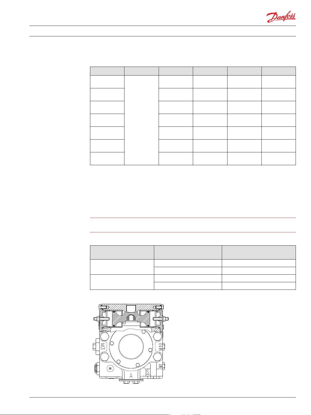
Multifunction valve, pressure regulation
Bypass Function
In some applications it is desirable to bypass fluid around the variable displacement pump when pump
shaft rotation is either not possible or not desired. For example, an inoperable vehicle may be moved to a
service or repair location or winched onto a trailer without operating the prime mover. To provide for
this, Series 90 pumps are designed with a bypass function.
The bypass is operated by mechanically rotating the bypass hex on both multifunction valves three (3)
turns counterclockwise (CCW). This connects working loop A and B and allows fluid to circulate without
rotating the pump and prime mover.
BC00000360en-US • Rev 0202 • February 2016 19
Page 20

Ø P
0
-0.05
[+0.000]
[-0.002]
F
min.
Minimum spline
engagement
D
B
max.
E
Mounting flange
(Ref)
Coupling
0.8 [0.03] R
preferred
P102 015E
Technical Information Series 90 Concrete Pumps
Features and Options
Auxiliary Mounting Pads
Auxiliary mounting pad specifications
Mounting pad Option code Spline coupling Frame size/Maximum torque N•m [lbf•ft]
130 180
SAE A AB 9T 16/32 106 [78] 120 [89]
SAE B BC 13T 16/32 334 [246] 324 [239]
SAE B-B BB 15T 16/32 368 [271] 368 [271]
SAE C CD 14T 12/24 741 [546] 628 [463]
SAE D DE 13T 8/16 741 [546] 1070 [789]
SAE E EF 13T 8/16 n/a 1070 [789]
SAE E EG 27T 16/32 n/a 1220 [900]
Mating pump requirements
The accompanying drawing provides the dimensions for the auxiliary pump mounting flange and shaft.
Pump mounting flanges and shafts with the dimensions noted below are compatible with the auxiliary
mounting pads on the Series 90 pumps. An O-ring is required when a pump is bolted to an aux pad. Refer
to outline drawings for more details and O-ring dimensions.
Auxiliary pump mounting flange and shaft
20 BC00000360en-US • Rev 0202 • February 2016
Page 21
W
P108 705E
Side 2
Technical Information
Features and Options
Displacement Limiter
Series 90 Concrete Pumps
Auxiliary pump dimensions
Flange size Units P diameter B maximum D F minimum
SAE A mm [in] 82.55
[3.25]
SAE B 101.6
[4.00]
SAE B-B 101.6
[4.00]
SAE C 127.0
[5.00]
SAE D 152.4
[6.00]
SAE E
13 teeth
SAE E
27 teeth
165.1
[6.50]
165.1
[6.50]
All Series 90 pumps are designed with optional mechanical displacement (stroke) limiters.
The maximum displacement of the pump can be set independently for forward and reverse using the
two adjustment screws.
7.4
[0.29]
10.7
[0.42]
10.7
[0.42]
14.3
[0.56]
14.3
[0.56]
18.0
[0.71]
18.0
[0.71]
32
[1.26]
41
[1.61]
46
[1.81]
56
[2.20]
75
[2.95]
75
[2.95]
75
[2.95]
13.5
[0.53]
14.2
[0.56]
16.1
[0.63]
18.3
[0.72]
20.8
[0.82]
20.8
[0.82]
27.0
[1.06]
Warning
Adjusting the displacement limiter with the machine running may result in leakage. If backed out too far,
the adjustment screw will come completely out of its threaded bore.
Displacement limiter location
Pump rotation Displacement limiter mounted on
servo side
Right [CW] 1 A
2 B
Left [CCW] 1 B
2 A
Displacement limitation at high
pressure side
Displacement limiter
BC00000360en-US • Rev 0202 • February 2016 21
Page 22

Technical Information
Features and Options
Series 90 Concrete Pumps
Shaft Torque
Frame size Lock nut wrench size and torque Adjusting screw
wrench size
internal hex
130 17 mm 48 N•m [35 lbf•ft] 5 mm 8.8 cm³/rev [0.53 in³/rev]
180 19 mm 125 N•m [92 lbf•ft] 6 mm 12.5 cm³/rev [0.76 in³/rev]
Approximate displacement change
per revolution of adjusting screw
The servo cylinders are equipped with gage port X11 and X12. These ports provide the possibility to
connect the servo system of the pump to the system loop. This feature connects the high pressure lines
with the servo system over check valves and provides a smooth concrete flow.
Shaft torque and spline lubrication
The rated torque is a measure of tooth wear and is the torque level at which a normal spline life of 2x10⁹
shaft revolutions can be expected. The rated torque presumes a regularly maintained minimum level of
lubrication via a moly-disulfide grease in order to reduce the coefficient of friction and to restrict the
presence of oxygen at the spline interface. It is also assumed that the mating spline has a minimum
hardness of Rc 55 and full spline depth. The rated torque is proportional to the minimum active spline
length.
Maximum torque ratings are based on torsional fatigue strength considering 100.000 full load reversing
cycles. However, a spline running in oil-flooded environment provides superior oxygen restriction in
addition to contaminant flushing. The rated torque of a flooded spline can increase to that of the
maximum published rating. A flooded spline would be indicative of a pump driven by a pump drive or
plugged into an auxiliary pad of a pump.
Maintaining a spline engagement at least equal to the Pitch Diameter will also maximize spline life. Spline
engagements of less than ¾ Pitch Diameter are subject to high contact stress and spline fretting.
Shaft torque for tapered shafts
The rated torque is based on the contact pressure between the shaft and hub surfaces with poor surface
contact areas. With an increased quality of the contact areas, the contact pressure between the shaft and
hub is increased and allows higher torque to be transmitted.
When a key is used for orientation of the hub on the shaft in conjunction with poor quality contact
surfaces, the transmitted torque will drop significantly. This is due to the key carrying the torque, which
limits the shaft torque carrying capability.
Maximum torque rating is based on an ideal contact area of 100 % and the retaining nut properly
torqued. This allows for the highest contact pressure between the shaft and the hub.
Shaft Availibility and Torque Ratings
Alignment between the mating spline's pitch diameters is another critical feature in determining the
operating life of a splined drive connection. Plug-in, or rigid spline drive installations can impose severe
radial loads on the shafts. The radial load is a function of the transmitted torque and shaft eccentricity.
Increased spline clearance will not totally alleviate this condition; but, increased spline clearance will
prevent mechanical interference due to misalignment or radial eccentricity between the pitch diameters
of the mating splines. Spline life can be maximized if an intermediate coupling is introduced between the
bearing supported splined shafts.
For multiple pump installations, consider load of the entire pump stack. All torques are additive. Include
charge pumps loads when calculating torques.
22 BC00000360en-US • Rev 0202 • February 2016
Page 23

First stageSecond stageThird
stage
for the first pumpM
e
1
second pump
for the M
e
2
next pumpfor the M
e
3
Input torqueM
e
P102 014E
Technical Information
Series 90 Concrete Pumps
Features and Options
Through torque diagram
Refer to the outline drawings for shaft dimensions.
Torque required by auxiliary pumps is additive. Ensure requirements don't exceed shaft torque ratings.
Shaft availability and maximum input torque - splined shafts
Option code Customer end Frame size/Maximum torque N•m [lbf•ft]
130 180
C8 27T 16/32 2693 [1986] 3125 [2304]
F1 13T 8/16 2303 [1700] 2303 [1700]
D5 W50x2x30x24x9g
-
3788 [2794]
Charge Pump
Charge flow is required on all Series 90 pumps applied in closed circuit installations. The charge pump
provides flow to make up internal leakage, maintain a positive pressure in the main circuit, provide flow
for cooling and filtration, replace any leakage losses from external valving or auxiliary systems, and to
provide flow and pressure for the control system.
Many factors influence the charge flow requirements. These factors include system pressure, pump
speed, pump swashplate angle, type of fluid, temperature, size of heat exchanger, length and size of
hydraulic lines, control response characteristics, auxiliary flow requirements, hydrostatic motor type, etc.
Unusual application conditions may require a more detailed review of charge pump sizing. Charge
pressure must be maintained at a specified level under all operating conditions to prevent damage to the
transmission. Danfoss recommends testing under actual operating conditions to verify this.
Charge pump sizing/selection
In most applications a general guideline is that the charge pump displacement should be at least 10% of
the total displacement of all components in the system. Unusual application conditions may require a
more detailed review of charge flow requirements. Refer to Selection of Drive line Components BLN-9885,
for a detailed procedure.
System features and conditions which may invalidate the 10% guideline include (but are not limited to):
Continuous operation at low input speeds (< 1500 min-1 (rpm))
•
High shock loading
•
Excessively long system lines (> 3m [9.8 ft])
•
Auxiliary flow requirements
•
Use of low speed high torque motors
•
High flushing flow
•
BC00000360en-US • Rev 0202 • February 2016 23
Page 24

80
70
60
50
40
30
20
10
3
6
9
12
15
21
18
500 1000 2000 3000 4000 4500
Speed min¯¹ (rpm)
US gal/min
l/min
17 cm • 1.03 in /Rev
14 cm • 0.86 in /Rev
34 cm • 2.07 in /Rev
3
3
26 cm • 1.60 in /Rev
3
3
3
20 cm • 1.2 in /Rev
3
3
3
3
3
0
0
47 cm • 2.9 in /Rev
3
3
90
24
65 cm • 3.9 in /Rev
3
3
P102 012E
Technical Information Series 90 Concrete Pumps
Features and Options
Contact your Danfoss representative for application assistance if your application includes any of these
conditions.
Available charge pump sizes and speed limits
Code Charge pump size
cm³ [in³]
F 26 [1.60] (only for 130cc) 3300
H 34 [2.07] 3100
J 47 [2.82] (only for 180cc) 2600
Charge pump flow and power curves
Charge pressure: 20 bar [350 psi]
Case drain: 80 °C (8.2 cSt) 180 °F (53 SUS)
Reservoir temperature: 70 °C (11 cSt) 160 °F (63 SUS)
Charge pump output flow
Rated speed
min-1 (rpm)
24 BC00000360en-US • Rev 0202 • February 2016
Page 25

3
2
1
6
500 1000 2000 3000
4000
4500
HP
kW
34 cm •
2.07 in /rev
26 cm
•
1.60 in /rev
20 cm
•
1.2 in /rev
17 cm
•
1.03 in /rev
14 cm
•
0.86 in /rev
11 cm
•
0.69 in /rev
5
4
3
2
1
4
0
0
3
3
3
3
3
3
Speed min (rpm)
-1
47 cm
•
2.9 in /rev
3
65 cm
•
3.9 in /rev
3
7
5
P102 013E
100
[26.4]
delta p - bar [psi]
0
0
Flow - l/min [gal/min]
P108687
Set Minimum
Set 12 bar/15 l/min
Set 22 bar/15 l/min
Set 30 bar/15 l/min
Set 37 bar/15 l/min
10
[145]
20
[290]
30
[435]
40
[580]
50
[725]
60
[870]
70
[1015]
200
[52.8]
300
[79.3]
P108688
A
B
T
M12
Technical Information
Features and Options
Series 90 Concrete Pumps
Charge pump power requirements
Loop Flushing Valve
For cooling and cleaning the fluid of the concrete pump system a loop flushing valve is available. This
valve is mounted directly on to the pump. To order a concrete pump with a loop flushing valve contact
your Danfoss representative.
Flushing characteristic (80°C) Manifold block
Loop Flushing Valve Schematic
BC00000360en-US • Rev 0202 • February 2016 25
Page 26

Technical Information Series 90 Concrete Pumps
Features and Options
Loop Flushing Valve Setting Capability
Loop flushing factory setting: 15 L/min to 22bar
The flushing valve is adjustable within the shown range.
26 BC00000360en-US • Rev 0202 • February 2016
Page 27

P108959
X12
L1
M4
X1
X2
M2
X9
M5
X11
X10
B
S
A
M12
X8
M1
M10
L2
M3
X3/M11
N
X8
X9
T
Charge pressure
relief valve
Displacement limiter screw
Displacement limiter seal nut
188 ± 1.2
132 ± 1.2
15.05 ± 0.5
25 ± 0.5
15.05 ± 0.5
91 ± 0.8
121.17 ± 1.2
176.6 ± 1.2
299.2 ± 1.2
128 ± 1.2
317 ± 1.2
300.2 ± 1.2
97 ± 0.8
48.8 ± 0.8
77 ± 0.15
117.6 ± 0.8
128 ± 1.2
95 ± 1.2
4 ± 0.5
300.2 ± 1.2
299.7 ± 1.2
166.8 ± 1.2
300.2 ± 1.2
290.9 ± 1.2
217.9 ± 1.2
209.3 ± 1.2
95 ± 1.2
299.7 ± 1.2
294.7 ± 1.2
209.3 ± 1.2
145.6 ± 1.2
102.1 ± 0.8
117.6 ± 0.8
86.6 ± 0.8
86.8 ± 0.8
5.2 ± 0.5
86.6 ± 0.8
77 ± 0.15
Multi-Function valve
system pressure B
Multi-Function valve
system pressure A
Technical Information Series 90 Concrete Pumps
Installation Drawings
Frame Size 130
Ports and port dimensions
Further dimensions can be found in Series 90 Axial Piston Pumps Technical Information 520L0603
BC00000360en-US • Rev 0202 • February 2016 27
Page 28

Technical Information Series 90 Concrete Pumps
Installation Drawings
Port description
Port Description Port Size UNF
A/B System Ports -
S Charge Inlet ISO 11926-1, 1-1/16-12
M2 System B Gauge ISO 11926-1, 9/16-18
M1 System A Gauge ISO 11926-1, 9/16-18
X9 System B Gauge ISO 11926-1, ¾-16/ISO 11926-1, 7/8-14
X8 System A Gauge ISO 11926-1, ¾-16/ISO 11926-1, 7/8-14
L1/L2 Case Drain ISO 11926-1, 1-5/16-12
T Case Drain ISO 11926-1, 7/8-14
M4/M5 Servo Gauge ISO 11926-1, 9/16-18
M3 Charge Pressure Gauge, accumulator ISO 11926-1, 9/16-18
X3/M11 Charge Gauge ISO 11926-1, 9/16-18
X1/X2 Control Signal Pressure Inlet ISO 11926-1, 9/16-18
X10 High Pressure Signal Output ISO 11926-1, 9/16-18
X11/X12 External Control Inlet DIN 3852-1, M22 x 1,5
M10 Charge Inlet Gauge ISO 11926-1, 9/16-18
M12 Charge Flush Gauge ISO 11926-1, ¾-16
N Case gauge ISO 11926-1, 9/16-18
28 BC00000360en-US • Rev 0202 • February 2016
Page 29

P108960
X12
L1
M4
X1
X2
M2
X9
M5
X11
X10
B
S
A
M12
X8
M1
M10
L2
M3
X3/M11
N
X8
X9
T
Charge pressure
relief valve
Displacement limiter screw
Displacement limiter seal nut
215 ± 1.2
159 ± 1.2
15.05 ± 0.5
25 ± 0.5
15.05 ± 0.5
92 ± 0.8
130.8 ± 0.1
211.3 ± 1.2
326.7 ± 1.2
7 ± 0.5
155 ± 1.2
337.9 ± 1.2
352.9 ± 1.2
120 ± 1.2
56 ± 0.8
93 ± 0.15
144.7 ± 1.2
155 ± 1.2
123 ± 1.2
25 ± 0.5
335.9 ± 1.2
326.9 ± 1.2
185.6 ± 1.2
93 ± 0.15
326.9 ± 1.2
321.9 ± 1.2
254.6 ± 1.2
228 ± 1.2
123 ± 1.2
35 ± 0.8
326.9 ± 1.2
315.9 ± 1.2
228 ± 1.2
152.1 ± 1.2
108.6 ± 0.8
144.7 ± 1.2
111 ± 0.8
111 ± 0.8
13 ± 0.5 79 ± 0.8
Multi-Function valve
system pressure B
Multi-Function valve
system pressure A
Technical Information Series 90 Concrete Pumps
Installation Drawings
Frame Size 180
Ports and port dimensions
Further dimensions can be found in Series 90 Axial Piston Pumps Technical Information 520L0603
BC00000360en-US • Rev 0202 • February 2016 29
Page 30

Technical Information Series 90 Concrete Pumps
Installation Drawings
Port description
Port Description Port size Metric Port size UNF
A/B System Ports - -
S Charge Pump Inlet M48 ISO 11926-1, 1-1/16-12
M2 System B Gauge M22 ISO 11926-1, 9/16-18
M1 System A Gauge M22 ISO 11926-1, 9/16-18
X9 System B Gauge M22 ISO 11926-1, ¾-16/DIN 3852-1, M22 x 1,5
X8 System A Gauge M22 ISO 11926-1, ¾-16/DIN 3852-1, M22 x 1,5
L1/L2 Case Drain M42 ISO 11926-1, 1 5/8-12
T Case Drain M22 ISO 11926-1, 7/8-14
M4/M5 Servo Gauge M14 ISO 11926-1, 9/16-18
M3 Charge Pressure Gauge M22 ISO 11926-1, 9/16-18
X3/M11 Charge Gauge M14 ISO 11926-1, 9/16-18
X1/X2 Control Signal Pressure Inlet M14 ISO 11926-1, 9/16-18
X10 High Pressure Signal Output M14 ISO 11926-1, 9/16-18
X11/X12 External Control Inlet M22 DIN 3852-1, M22 x 1,5
M10 Charge Inlet Gauge M14 ISO 11926-1, 9/16-18
M12 Charge Flush Gauge M14 ISO 11926-1, ¾-16
N Case Gauge M14 ISO 11926-1, 9/16-18
30 BC00000360en-US • Rev 0202 • February 2016
Page 31

Technical Information Series 90 Concrete Pumps
BC00000360en-US • Rev 0202 • February 2016 31
Page 32

Danfoss
Power Solutions GmbH & Co. OHG
Krokamp 35
D-24539 Neumünster, Germany
Phone: +49 4321 871 0
Danfoss
Power Solutions ApS
Nordborgvej 81
DK-6430 Nordborg, Denmark
Phone: +45 7488 2222
Danfoss
Power Solutions (US) Company
2800 East 13th Street
Ames, IA 50010, USA
Phone: +1 515 239 6000
Danfoss
Power Solutions Trading
(Shanghai) Co., Ltd.
Building #22, No. 1000 Jin Hai Rd
Jin Qiao, Pudong New District
Shanghai, China 201206
Phone: +86 21 3418 5200
Products we offer:
Comatrol
www.comatrol.com
Schwarzmüller-Inverter
www.schwarzmuellerinverter.com
Turolla
www.turollaocg.com
Hydro-Gear
www.hydro-gear.com
Daikin-Sauer-Danfoss
www.daikin-sauer-danfoss.com
Bent Axis Motors
•
Closed Circuit Axial Piston
•
Pumps and Motors
Displays
•
Electrohydraulic Power
•
Steering
Electrohydraulics
•
Hydraulic Power Steering
•
Integrated Systems
•
Joysticks and Control
•
Handles
Microcontrollers and
•
Software
Open Circuit Axial Piston
•
Pumps
Orbital Motors
•
PLUS+1® GUIDE
•
Proportional Valves
•
Sensors
•
Steering
•
Transit Mixer Drives
•
Danfoss Power Solutions is a global manufacturer and supplier of high-quality hydraulic and
electronic components. We specialize in providing state-of-the-art technology and solutions
that excel in the harsh operating conditions of the mobile off-highway market. Building on
our extensive applications expertise, we work closely with our customers to ensure
exceptional performance for a broad range of off-highway vehicles.
We help OEMs around the world speed up system development, reduce costs and bring
vehicles to market faster.
Danfoss – Your Strongest Partner in Mobile Hydraulics.
Go to www.powersolutions.danfoss.com for further product information.
Wherever off-highway vehicles are at work, so is Danfoss. We offer expert worldwide support
for our customers, ensuring the best possible solutions for outstanding performance. And
with an extensive network of Global Service Partners, we also provide comprehensive global
service for all of our components.
Please contact the Danfoss Power Solution representative nearest you.
Danfoss can accept no responsibility for possible errors in catalogues, brochures and other printed material. Danfoss reserves the right to alter its products without notice. This also applies to
products already on order provided that such alterations can be made without changes being necessary in specifications already agreed.
All trademarks in this material are property of the respective companies. Danfoss and the Danfoss logotype are trademarks of Danfoss A/S. All rights reserved.
BC00000360en-US • Rev 0202 • February 2016 www.danfoss.com
Local address:
©
Danfoss A/S, 2016
 Loading...