

Page 1

DataTime® DF-1012
Time & Temperature Display
Installation and Operation Manual
DD2563927 Rev 02—25 November 2014
201 Daktronics Drive PO Box 5128 Brookings, SD 57006
tel 800-843-5843 fax 605-697-4700
Table of Contents 1
www.daktronics.com
Page 2

DD2563927
Product 1279
Rev 02—25 November 2014
Copyright © 2013-2014
All rights reserved. While every precaution has been taken in the preparation of this manual, the publisher assumes no
responsibility for errors or omissions. No part of this book covered by the copyrights hereon may be reproduced or copied in any
form or by any means—graphic, electronic, or mechanical, including photocopying, taping, or information storage and retrieval
systems—without written permission of the publisher.
Daktronics is a registered trademark of Daktronics, Inc.
All other trademarks are the property of their respective companies.
Page 3

Table of Contents
Section 1: Introduction .......................................................................................................................................... 1
1.1 Safety Precautions ................................................................................................................................................ 1
1.2 Product Overview ................................................................................................................................................ 1
Section 2: Mechanical Installation ....................................................................................................................... 3
2.1 Mechanical Installation Overview ..................................................................................................................... 3
2.2 Support Structure Design .................................................................................................................................... 3
2.3 Lifting the Display ............................................................................................................................................... 4
2.4 Temperature and Light Sensor ........................................................................................................................... 4
Locating the Temperature Sensor ............................................................................................................... 5
Connecting the Temperature Sensor .......................................................................................................... 5
Connection to the Sensor ............................................................................................................................. 6
Section 3: Electrical Installation ........................................................................................................................... 7
3.1 Preparing for Power/Signal Connection .......................................................................................................... 7
3.2 Power Connections .............................................................................................................................................. 7
3.3 Grounding Connections ...................................................................................................................................... 7
3.4 Power Installation ................................................................................................................................................ 8
Installation With Ground and Neutral Conductors Provided ............................................................... 8
Installation With Only A Neutral Conductor Provided .......................................................................... 8
3.5 Lightning Protection ............................................................................................................................................ 8
3.6 Signal Connection ................................................................................................................................................ 9
Host/Client Definitions .............................................................................................................................. 9
Direct – Outdoor Connection ................................................................................................................... 10
Direct – Indoor Connection ...................................................................................................................... 11
Section 4: Maintenance and Troubleshooting .................................................................................................. 15
4.1 Component Location and Access .................................................................................................................... 15
4.2 Troubleshooting ................................................................................................................................................. 16
Error Codes .................................................................................................................................................. 17
Power On Self-Test ..................................................................................................................................... 17
Section 5: Parts Replacement ............................................................................................................................ 19
5.1 Replacement Parts List ...................................................................................................................................... 19
5.2 Instructions for Replacing Parts ....................................................................................................................... 20
Replacing a Digit ......................................................................................................................................... 20
Replacing a Digit Segment ......................................................................................................................... 20
Segmentation and Digit Designation ....................................................................................................... 21
Replacing an LED Driver ........................................................................................................................... 21
Replacing a Signal Surge Board ............................................................................................................... 22
Table of Contents i
Page 4

Section 6: Daktronics Exchange and Repair & Return Programs .................................................................. 25
6.1 Exchange Program ............................................................................................................................................. 25
Before Contacting Daktronics ................................................................................................................... 25
6.2 Repair & Return Program ................................................................................................................................. 25
Shipping Address........................................................................................................................................ 26
6.3 Daktronics Warranty and Limitation of Liability .......................................................................................... 26
Section 7: DM-100 Controller .............................................................................................................................. 27
7.1 DM-100 Overview .............................................................................................................................................. 27
7.2 DataMaster Insert ............................................................................................................................................... 27
7.3 Time & Temperature Display Operation ........................................................................................................ 27
Time & Temperature Display Setup ........................................................................................................ 28
Menu Items .................................................................................................................................................. 29
Daylight Savings Setting ............................................................................................................................ 29
Set Time ....................................................................................................................................................... 29
Set Date ......................................................................................................................................................... 30
Degrees F Temperature Offset .................................................................................................................. 30
Set Degrees C Temperature Offset ........................................................................................................... 31
Time & Temperature Format/Hold Settings .......................................................................................... 31
Sequence Order ........................................................................................................................................... 32
LED Test ....................................................................................................................................................... 32
Modem Settings ........................................................................................................................................... 32
Display Status .............................................................................................................................................. 33
Diagnostics ................................................................................................................................................... 33
Dimming....................................................................................................................................................... 33
Appendix A: Reference Drawings .......................................................................................................................... 37
Appendix B: Temperature Sensor Mounting (ED-18601) ..................................................................................... 39
Appendix C: DataTime® Quick Installation Reference (A-176249) ...................................................................... 41
Appendix D: DataTime® Quick Start Reference (DD2563921) .............................................................................. 43
Appendix E: Daktronics Warranty and Limitation of Liability (SL-02374) .......................................................... 45
ii Table of Contents
Page 5
Section 1: Introduction
This manual provides the necessary information to install and service a Daktronics DataTime® DF-1012 Time &
Temperature display. Contact Daktronics Technical Support with questions before or during the installation process.
1.1 Safety Precautions
• Read and understand these instructions before installing the display.
• Do not drop the controller or allow it to get wet.
• Properly ground the display with a ground rod at the sign location.
• Disconnect power when the display is not in use.
• Disconnect power when servicing the display.
• Do not modify the display structure or attach any panels or coverings without the express written
consent of Daktronics.
Figure 1 shows a label found inside the display where the model number and power requirements are
located. When calling Daktronics
Customer Service, please have this
information available to ensure
that a request is serviced as
quickly as possible.
1.2 Product Overview
DAKTRONICS
201 DAKTRONICS DR.
BROOKINGS, SD 57006-5128
Figure 1: Display Identication Label
ASSY NO.
SER. NO.
MFG DATE
PHONE 800-325-8766
LL-2306R01
DataTime® Time & Temperature displays show temperatures in Fahrenheit or Celsius (three digits, degree
symbol, and F or C character) and 12- or 24-hour time.
These displays have the following features:
• LEDs illuminate numeric digits.
• Maximum power usage is 180 W using a 120 V power input.
• Cabinets are constructed of heavy-gauge aluminum.
• Digit faceplates are black and set directly into the surface of the display.
• Mounting weights and dimensions for each model are listed in Section 2.1 of this manual.
• DataTime® displays use a DM-100 handheld controller. See Section 7 for operating instructions.
DataTime® display model numbers - DF-1012-HH-C - are defined as follows:
DF-1012
HH
C
= Outdoor Digit Display
= Digit height in inches (10, 13, 18, 24)
= LED Color- R (Red) or A (Amber)
Introduction 1
Page 6

Page 7
Section 2: Mechanical Installation
Daktronics’ engineering staff must approve any changes that may affect the display’s weather tightness. Before any
modifications are made, submit detailed drawings of the changes to Daktronics for evaluation and approval or the
warranty will be void.
Daktronics is not responsible for the installation or the structural integrity of support structures done by others. It is
the customer’s responsibility to ensure that a qualified structural engineer approves the structure and any additional
hardware.
2.1 Mechanical Installation Overview
Mechanical installation typically consists of mounting the display and any accompanying panels to the
support structure.
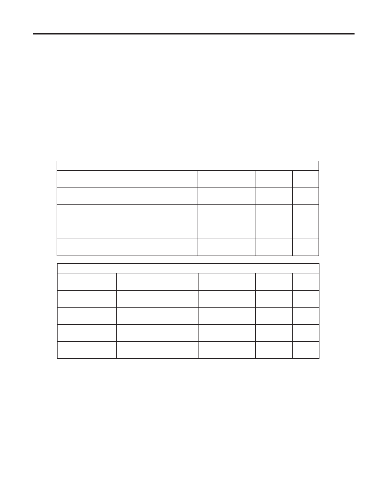
The tables below show the weights and dimensions for each model.
120 V AC
Model
DF-1012-10-R or A
DF-1012-13-R or A
DF-1012-18-R or A
DF-1012-24-R or A
Dimensions (H x W x D)
Feet and Inches (Meters)
1'3" x 3' x 6"
(0.39 x 0.89 x 0.16)
1'6" x 4' x 6"
(0.46 x 1.22 x 0.16)
2' x 5' x 6"
(0.61 x 1.53 x 0.16)
2' 6"x 6'6" x 6"
(0.77 x 1.99 x 0.16)
Uncrated Weight
Pounds (kg)
25 (10) 10 90
27 (12) 13 100
43 (20) 18 130
58 (26) 24 180
Digit Size Watts
230 V AC
Model
DF-1012-10-R or A
DF-1012-13-R or A
DF-1012-18-R or A
DF-1012-24-R or A
Dimensions (H x W x D)
Feet and Inches (Meters)
1'3" x 3' x 6"
(0.39 x 0.89 x 0.16)
1'6" x 4' x 6"
(0.46 x 1.22 x 0.16)
2' x 5' x 6"
(0.61 x 1.53 x 0.16)
2' 6"x 6'6" x 6"
(0.77 x 1.99 x 0.16)
2.2 Support Structure Design
While DataTime® displays are designed for wall or pole mounting, every installation is different. Actual site
demands dictate the appropriate mounting method. DataTime® DF-1012 models are designed to be inserted
into an existing sign cabinet or for rear attachment using the threaded inserts in the rear of the display.
Uncrated Weight
Pounds (kg)
25 (10) 10 90
27 (12) 13 100
43 (20) 18 130
58 (26) 24 180
Digit Size
Max.
Watts
Mechanical Installation 3
Page 8
2.3 Lifting the Display
Hand lift displays into the support structure.
Note: Daktronics assumes no liability for display damage or injury resulting from incorrect setup or incorrect
lifting methods.
2.4 Temperature and Light Sensor
Reference Drawings:
Time & Temp Power/Signal Hookup ....................................................... Drawing A-938369
Installation, Temp Sensor, G3 .................................................................Drawing A-184840
Shop Drawings .....................................................................................Refer to Appendix A
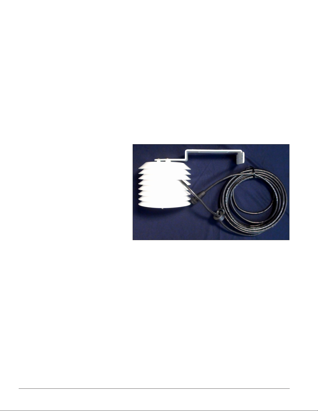
All displays in the DataTime® series use a light sensor to regulate dimming functions and a temperature
sensor to collect and display temperature information. Both temperature and light-monitoring electronics are
located in the sensor housing, shown in Figure 2.
The Daktronics Controller Area
Network (CAN) Temperature/Light
Sensor is pre-installed in a protective
housing. The assembly includes the
sensor, mounting bracket, and cabling
with a quick-connect plug. Instructions
that follow describe the placement
and connection of the device. Review
the wiring diagram and connection
illustration in Drawing A-184840 before
beginning.
Dimming involves decreasing overall
display intensity, both for better display
viewing and to prolong LED life. Set the
brightness level highest during the day
to compete with daylight, and lower at night.
Figure 2: Temperature Sensor Housing and Cabling
4 Mechanical Installation
Page 9
Locating the Temperature Sensor
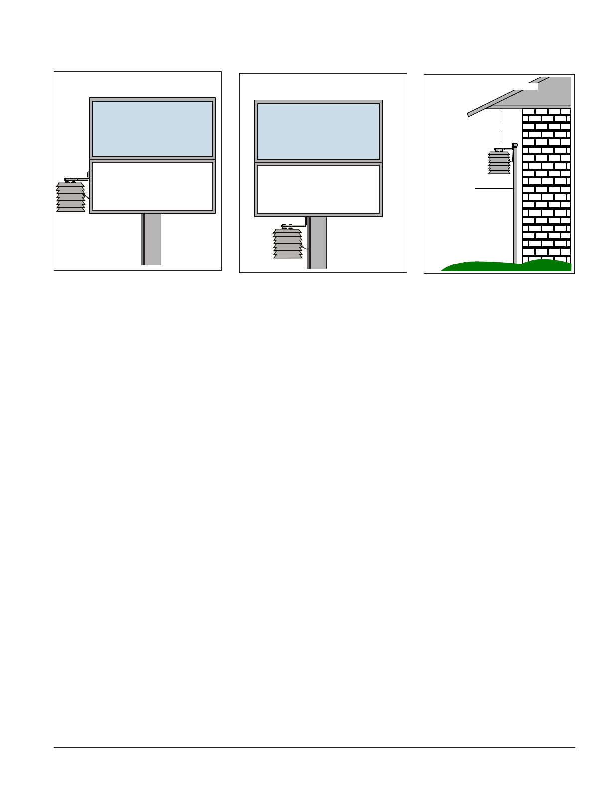
Refer to Figure 3, Figure 4, and Figure 5 for recommendations.
Temperature Sensor Attached to
North Side of Display
First
State Bank
BANK HOURS
8 AM - 5 PM
Figure 3: Temperature Sensor Mounted
on Display
Recommendations and Requirements:
• First choice for the sensor location is a north eave or northern exposure, away from direct sunlight
and above grass. This location gives extra stability and accuracy to the sensor because of the
additional shade usually provided by a northern exposure.
Temperature Sensor Attached to
Display Structure
First
State Bank
BANK HOURS
8 AM - 5 PM
Figure 4: Temperature Sensor Mounted
on Structure
Mounted under north eave
▲
1 ft.
▼
1/2” conduit
(supplied by customer)
Vegetation
Figure 5: Temperature Sensor
Mounted Under North Eave
• Second choice for locating the sensor is on the display itself, or somewhere on the display structure.
(This works best with light-colored displays.) Locate the sensor above, below, or on the northern edge
of the display to keep the sensor shaded as much as possible. Sensor readings are more accurate if
there is grass below the sign, rather than concrete or asphalt.
Things to Avoid:
• The sensor requires a location away from chimneys, air conditioners, vents, tar roofs, concrete, and
parking lots, all of which can cause abnormal temperature fluctuations and incorrect sensor readings.
For accurate readings under these conditions, keep a separation of at least 20-30 feet horizontally and
8 feet vertically between the sensor and the influential element.
• Locations that restrict air movement are also unsatisfactory.
• When a display has two faces, do not mount the sensor between the faces.
Connecting the Temperature Sensor
After properly locating the sensing device, follow these steps to connect it with the display:
1. The temperature sensor is equipped with outdoor-rated cable that has a four-pin quick-connect plug
on the end. Route the cable from the sensor to the back of display.
2. A four-pin quick-connect jack located on the back panel of the display connects the sensor cable to
the display. Refer to the Shop Drawing for the exact location of the jack on a particular model. Simply
plug in the sensor cable and tighten the connector collar to the display. A factory-installed internal
cable, runs from the sensor jack to the TB1 connector on the driver inside the housing.
Mechanical Installation 5
Page 10
3. Secure any additional cable to prevent the quick-connect plug from being pulled out of the display
and to protect it from weather or vandalism.
Note: The temperature sensor is equipped with 25 feet (7.6 m) of cable. If necessary, the cable can be cut to
shorten and then be re-terminated. In addition, the cable can be extended by using a four-conductor shielded
cable to a distance of 750 feet (230 m). When not using the provided weather-resistant cable, the cable from
the sensor to the display needs to be in conduit.
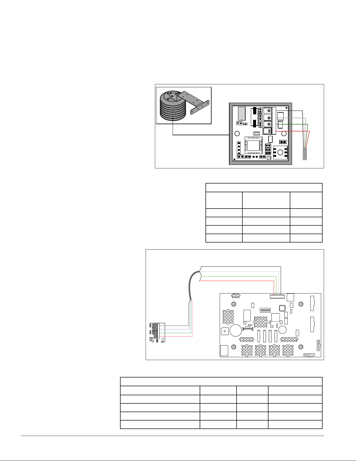
Connection to the Sensor
If it is necessary to reconnect the wires to
the temperature sensor terminal block,
refer to Figure 6 and the table for the
correct connections.
Note: Make sure the power is off before
making any connections.
Connection from Sensor to the
Display Driver
If the distance from the temperature
sensor to the display is greater than the
provided 25 foot (7.6 m) cable, connect a 4-conductor shielded
cable from the sensor to TB1 on the display driver board.
1. The display’s power must be OFF when attaching the
internal sensor cable to the host driver.
2. Connect the temperature sensor to the terminal
block (TB1) on the host driver. Refer to Figure 7
and the table for the correct
connections.
Figure 6: Temperature Sensor Connection
CAN Temperature Sensor to MASC Driver
W-1234
CAN Temperature Sensor Wiring
+5V
0
8
GND - Black
CAN L - White
CAN H - Green
+5V - Red
4
G
L
H
1
Wiring to Temperature Sensor
Wire Color
Red Pin 1 5 V
Green Pin 2 CAN H
White Pin 3 CAN L
Black Pin 4 GND
Terminal Block
Pin No.
Shield GND – Black
CAN L – White
CAN H – Green
+5V – Red
Pin 2
Pin 3
Pin 4
Function
Pin 5
Temperature
Sensor
GND – Black
4
G
CAN L – White
L
CAN H – Green
H
+5V – Red
1
+5V
Figure 7: Temperature Sensor to Display Driver Connections
Connections from Temperature Sensor to Host Driver
Temperature Sensor (TB1) Wire Color Function Host Driver (TB1)
Pin 1 Red 5 V Pin 2
Pin 2 Green CAN H Pin 3
Pin 3 White CAN L Pin 4
Pin 4 Black GND Pin 5
6 Mechanical Installation
Page 11

Section 3: Electrical Installation
Only qualified individuals should perform power routing and termination to the display. It is the responsibility of the
electrical contractor to ensure that all electrical work meets or exceeds local and national codes. Improper installation
could result in serious damage to the equipment and be hazardous to personnel.
3.1 Preparing for Power/Signal Connection
Reference Drawing:
Time & Temp Power/Signal Hookup ....................................................... Drawing A-938369
Electrical installation consists of the following process:
• Providing power and ground to a disconnect near the display.
• Routing power and ground from the main disconnect to the display driver/power enclosure.
• Connecting the display ground to a grounding electrode at the display location.
• Routing the control signal cable from the control location to the display location.
Drawing A-938369 provides detailed instructions for power and signal connections for time and temperature
displays, including connection of the temperature sensor and connections between host and client displays.
Refer to this drawing before completing any part of the electrical installation.
3.2 Power Connections
Daktronics DataTime® displays have removable or hinged front panels that allow access to the digits, cabling,
and other electronic components.
DataTime® outdoor displays require a dedicated, 120 V circuit (or 230 V for international use) for incoming
power. The display itself has no breakers or fuses.
WARNING: The display circuit must be fused at 15 A, and all conductors must be designed to pass a 15 A
current in normal operation. Failure to meet wiring and over current protection device requirements is a
violation of the National Electrical Code and will void the display’s warranty.
3.3 Grounding Connections
Reference Drawing:
Enclosed Driver, 4 Column Reference ....................................................Drawing A-938300
Displays MUST be grounded according to Article 250 of the National Electrical Code and according to
Daktronics specifications or the warranty will be void. Daktronics requires a resistance-to-ground of 10 ohms
or less.
The contractor performing the electrical installation must verify ground resistance. Technicians from
Daktronics Sales and Service offices can also provide this service.
Proper grounding is necessary for reliable equipment operation. It also protects the equipment from
damaging electrical disturbances and lightning. Drawing A-938300 illustrates where to connect the ground
wire at the driver enclosure.
Electrical Installation 7
Page 12

Important points about grounding:
• Follow local and national codes: The material of an earth-ground electrode differs from region to
region and from conditions present at site. Consult any electrical codes that apply.
• Support structure cannot be used as an earth-ground electrode: Daktronics does not recommend
using the support structure as an earth-ground electrode; concrete, primer, corrosion, and other
factors make the support structure a poor ground.
• Note: The support structure may be used as an earth-ground electrode only if designed to do so. A
qualified inspector must approve the support structure and grounding methods.
• One grounding electrode for each display face
3.4 Power Installation
There are two types of power installation: Installation with ground and neutral conductors provided,
and installation with only a neutral conductor provided. These two power installations differ slightly, as
described in the following paragraphs:
Installation With Ground and Neutral Conductors Provided
For this type of installation, the power circuit must contain an isolated earth-ground conductor. In this
circumstance, do not connect neutral to ground at the disconnect or at the display as this would violate
electrical codes and void the warranty.
Use a disconnect so that all ungrounded lines can be disconnect. The National Electrical Cod requires the use
of a lockable power disconnect within sight of or at the display.
Installation With Only A Neutral Conductor Provided
Installations where no grounding conductor is provided must comply with Article 250-32 of the National
Electrical Code. If the installation in question meets all of the requirements of Article 250-32, observe the
following guidelines:
• Connect the grounding electrode cable at the local disconnect, never at the display driver/power
enclosure.
• Use a disconnect that opens all of the ungrounded phase conductors.
3.5 Lightning Protection
Using a disconnect near the display to completely cut all current-carrying lines significantly protects the
circuits against lightning damage. For this system to provide protection, disconnect power when the display
is not in use.
Disconnect the DM-100 control console from power and from the signal J box when the system is not being
used. The same surges that may damage the display’s driver can also damage the DM-100 console’s circuitry.
8 Electrical Installation
Page 13
3.6 Signal Connection
Signal
Connection
12V DC
Out
Surge Supression Board
Driver Board
Power
Photo/Temp Sensor
Connection
Protocol
Jack
Address
Switch
Neutral Here
+
+
+
SIGNAL
IN
TB3
SIGNAL
OUT
12V DC
OUT
SIGNAL OUT
–
+
J1
24VDC
RADIO
J2
SHIELD
–
+
SIGNAL IN
Reference Drawings
4 Column MASC Specications .............................................................. Drawing A-166216
Time & Temp Power/Signal Hookup ....................................................... Drawing A-938369
Enclosed Driver, 4 Column Reference ....................................................Drawing A-938300
Route power and signal cables into the display from the side or rear. There are 7/8" knockouts for 1/2" conduit
fittings on the sides of all DataTime® cabinets and on the back
panels. All power and signal wiring terminates at the driver
enclosure.
Open the display cabinet by turning the latches on the hinged
doors. To access the driver enclosure, open the access door and
remove the cover. Refer to the Shop Drawings for the access
location for the display.
Refer to Drawing A-938300 for a complete review of power and
signal connections for direct connection to the displays. Drawing
A-166216 provides connection specifications for the four-column
drivers used in all DataTime® Time & Temperature displays.
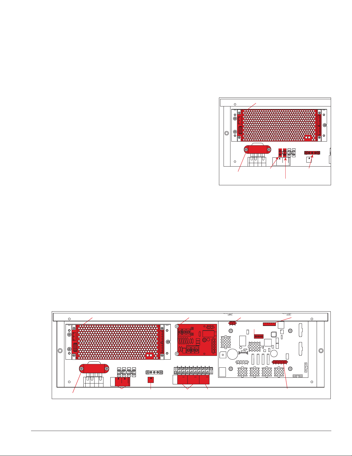
Power and signal connections, illustrated in Figure 8, are similar
for both drivers.
Power Supply
6 5
8 7
0
3
2
1
Transformer
4
BLK OR
SMOOTH
8
TOP
ORG
WHT OR
GROOVED
6
7
5
N.C.
BRN
Connect 120V
AC Line Here
120VAC
LINE
TB4
MAIN POWER
Connect
NEUT.
GND
Connect Earth
Ground Wire
Here
Figure 8: Power and Ground Wire Connections
Inside Display
Host/Client Denitions
Reference Drawings:
Multipurpose 4 Column LED Driver II Specications ..............................Drawing A-166216
Host/Client Denitions ............................................................................. Drawing A-185236
One driver at each display installation is designated as the host driver, which receives its signal directly
from the DataMaster controller on its Signal IN terminals. It is the only driver that is connected to the photo/
temperature sensor. The Signal OUT terminals on the host connect to the client driver.
Select the host driver by inserting the Protocol-4 plug into the five-pin protocol jack (J20). Refer to Figure 9 or
Drawing A-166216 for location of the protocol jack.
Power Supply Surge Supression Board
SIGNAL OUT
SIGNAL IN
6 5
8 7
0
3
2
1
4
BLK OR
SMOOTH
WHT OR
GROOVED
8
6
7
5
N.C.
TOP
BRN
ORG
Transformer
Figure 9: DataTime Driver Enclosure with 4-Column Driver
120VAC
NEUT.
LINE
TB4
MAIN POWER
Power
Connections
GND
Ground
Connection
+
SIGNAL
TB3
IN
Signal
Connection
+
–
SHIELD
–
+
+
SIGNAL
OUT
+
12V DC
OUT
12V DC
Out
J1
24VDC
RADIO
J2
Driver Board
Power
Address
Switch
With a time and temperature display there is usually only one host and one client. The client driver receives
signal from the host driver, and the client can re-drive this signal to other drivers.
Electrical Installation 9
Photo/Temp Sensor
Connection
Protocol
Jack
Page 14
Direct – Outdoor Connection
Reference Drawings:
Riser Diagram, Outdoor Wire Control ..................................................... Drawing A-164988
Time & Temp Power/Signal Hookup ....................................................... Drawing A-938369
Enclosed Driver, 4 Column .....................................................................Drawing A-938300
A direct-controlled display uses a current loop connection from the J box at the base of the display to the
driver enclosure in the display. All the power and signal wiring terminates at the driver enclosure. The
DataMaster controller receives its power from the display. The display layout is shown in Drawing A-164988.
Note: The cable from the J box to the display needs to be routed through conduit or the display pole to protect
it from weather and vandalism.
1. Mount the J box at the display.
2. Select the host driver by inserting the Protocol-4 plug into the five-pin protocol jack (J20).
3. Route a six-conductor, 18 AWG, shielded signal cable through conduit from the J box to the driver
enclosure in the host display. Fifty feet (15.2 m) of signal wire is provided.
4. Connect the signal wire from the J box to the driver enclosure as shown in Figure 10 and listed in the
table. Refer to Drawings A-938369 and A-938300 for additional information.
SIGNAL OUT
+
–
J1
24VDC
SHIELD
SIGNAL IN
–
+
RADIO
J2
6 5
8 7
0
3
4
BLK OR
SMOOTH
8
7
N.C.
TOP
ORG
Power/Ground
Connections
2
1
120VAC
NEUT.
LINE
WHT OR
GROOVED
TB4
6
5
MAIN POWER
BRN
+
+
+
SIGNAL
GND GND
SIGNAL
12V DC
TB3
IN
OUT
OUT
Black
Red
Red
1
2
3
Black
4
White
5
Green
6
7
Brown
Grn
Wht
Brn
Red
Blk
Blu
Red
Blk
Blue
8
9
Figure 10: Direct Connection from Outdoor Location
J-box
6 5
8 7
0
3
2
1
4
120VAC
LINE
BLK OR
SMOOTH
WHT OR
GROOVED
TB4
8
6
7
5
MAIN POWER
N.C.
TOP
BRN
ORG
Black and Red =
Signal to Client Display
DM-100
Controller
SIGNAL OUT
+
–
J1
24VDC
SHIELD
SIGNAL IN
–
+
RADIO
J2
+
+
+
SIGNAL
SIGNAL
NEUT.
12V DC
TB3
IN
OUT
OUT
10 Electrical Installation
Page 15

Wiring from J-Box to Host Driver Enclosure
J-Box Pin Number Cable Color Enclosure Terminal Block
Pin 1 Red 12 V DC Out (+)
Pin 5 Black 12 V DC Out (-)
Pin 5 White Signal IN (-)
Pin 6 Green Signal IN (+)
Pin 8 Brown Signal OUT (+)
Pin 9 Blue Signal OUT (-)
5. Mount the temperature sensor as described in Section 2.4, and connect the quick-connect cable to the
four-pin quick connect on the back of the display.
6. The DataMaster controller plugs into the J box using a DB9M to DB9F serial cable.
Direct – Indoor Connection
Reference Drawings:
Riser Diagram, Indoor Wire Control ........................................................ Drawing A-175342
Time & Temp Power/Signal Hookup ....................................................... Drawing A-938369
Enclosed Driver, 4 Column .....................................................................Drawing A-938300
A direct-controlled display can also be used from a J box at in indoor location. In that case, only two, 22
AWG, signal wires will need to be connected to the J box and a wall pack transformer will be used for power
to the DataMaster controller. The distance from the indoor J box to the host driver can be up to 2,000 ft (600
m). Refer to Figure 11 and Drawing A-175342 for system layout and signal connections.
1. Mount the J box at an indoor location.
2. Select the host driver by inserting the Protocol-4 plug into the five-pin protocol jack (J20).
3. Route a four-conductor, 18 AWG, shielded signal cable through conduit from the J box to the driver
enclosure in the host display.
Electrical Installation 11
Page 16

4. Connect the signal wire, through conduit, from the J box to the driver enclosure as shown in Figure
+
+
+
TB3
+
+
+
TB3
Red
Black
Host Display Client Display
11 and listed in the table. Refer to Drawings A-938369 and A-938300 for additional information.
SIGNAL OUT
+
–
J1
24VDC
SHIELD
SIGNAL IN
–
+
RADIO
J2
6 5
8 7
0
3
4
BLK OR
SMOOTH
8
7
N.C.
TOP
ORG
Power/Ground
Connections
Grn
Wht
6 5
2
1
120VAC
NEUT.
LINE
WHT OR
GROOVED
TB4
6
5
MAIN POWER
BRN
Blu
Blk
Brn
Red
+
+
+
SIGNAL
GND
SIGNAL
12V DC
TB3
IN
OUT
OUT
Black
Red
1
2
3
4
White
5
Green
6
7
Brown
8
9
Blue
8 7
0
3
2
1
4
120VAC
LINE
BLK OR
SMOOTH
WHT OR
GROOVED
TB4
8
6
7
5
N.C.
TOP
BRN
ORG
Black and Red =
Signal to Client Display
J-box
120 VAC
Plug-in
Transformer
Figure 11: Direct Connection from Indoor Location
Wiring from Indoor J-Box to Host Driver Enclosure
J-Box Pin Number Cable Color Enclosure Terminal Block
Pin 5 White Signal IN (-)
Pin 6 Green Signal IN (+)
Pin 8 Brown Signal OUT (+)
Pin 9 Blue Signal OUT (-)
SIGNAL OUT
+
–
J1
24VDC
SHIELD
SIGNAL IN
–
+
RADIO
J2
+
+
+
SIGNAL
GND
NEUT.
MAIN POWER
TB3
IN
DM-100
Controller
SIGNAL
12V DC
OUT
OUT
5. Mount the temperature sensor according to Section 2.4, and connect the quick-connect cable to the
four-pin quick connect on the back of the display.
6. The DataMaster controller plugs into the J box using a DB9M to DB9F serial cable.
7. Plug the wall pack transformer into a wall socket and the other end into the DM-100 controller.
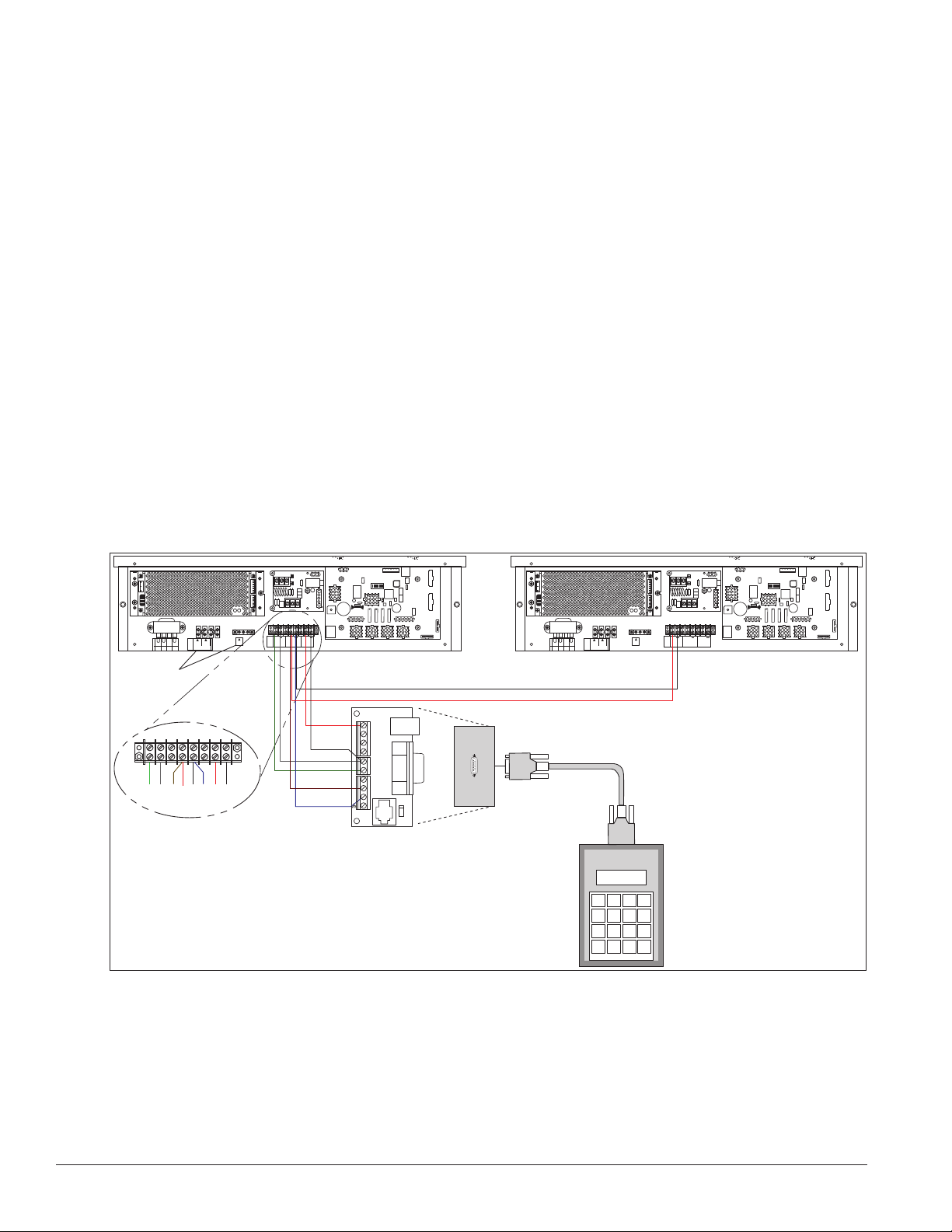
8. Client Definitions and Address Settings
Reference Drawings:
Multipurpose 4 Column LED Driver II Specications ..............................Drawing A-166216
Host/Client Denitions ............................................................................. Drawing A-185236
One driver at each display installation is designated
as the host driver, and all other displays are clients.
The Signal OUT terminals on the host are used to
connect to the client drivers. Refer to Figure 12 and
Drawing A-185236 for an illustration of the client/
host display connection.
12 Electrical Installation
Client drivers receive signal from the host driver on
Figure 12: Host, Signal Out to Client, Signal In
Page 17

the Signal IN terminals and can re-drive this signal to other client drivers on the Signal OUT terminals.
The maximum wire distance between the host driver and client driver is 2,000 feet.
Some multiple-module DataTime® displays use host/client displays, which do not contain a driver and may
use either client or host digit outputs. The DF-1012 model uses the host/client configuration.
Address Settings
The address of each driver is set using an eight-position DIP-switch
(S1), and the address is based on that driver’s position in the display
system. If a single-line display is used, the address will typically be
Address 01. This means that switch 1 is turned ON and the remaining
7 switches are in the OFF position. This is the default address set
when each display is shipped. In multiple-product displays, the
address determines which line of information is shown on the driver’s
digits. The switch is set using a binary address. Use the table and the
examples in Figure 13 for setting the address.
Note: Some older drivers set the address of each driver using an
address plug (Daktronics part # 0A-1150-0122) in J19. The address,
either using a switch or a plug, needs to be set for each driver.
OFF
ON
1
OFF
ON
1
OFF
3
2
3
2
Address 1
5
4
Address 2
5
4
Address 3
7
6
8
7
6
8
Binary Address Settings
Switch Number
Address
1
2
3
4
5
6
7
8
9
10
11
12
13
14
15
1 2 3 4 5 6 7 8
ON OFF OFF OFF OFF OFF OFF OFF
OFF ON OFF OFF OFF OFF OFF OFF
ON ON OFF OFF OFF OFF OFF OFF
OFF OFF ON OFF OFF OFF OFF OFF
ON OFF ON OFF OFF OFF OFF OFF
OFF ON ON OFF OFF OFF OFF OFF
ON ON ON OFF OFF OFF OFF OFF
OFF OFF OFF ON OFF OFF OFF OFF
ON OFF OFF ON OFF OFF OFF OFF
OFF ON OFF ON OFF OFF OFF OFF
ON ON OFF ON OFF OFF OFF OFF
OFF OFF ON ON OFF OFF OFF OFF
ON OFF ON ON OFF OFF OFF OFF
OFF ON ON ON OFF OFF OFF OFF
ON ON ON ON OFF OFF OFF OFF
ON
1
OFF
ON
1
Figure 13: Common Address Settings
3
2
3
2
5
4
Address 4
5
4
7
6
8
7
6
8
Electrical Installation 13
Page 18

Page 19

Section 4: Maintenance and Troubleshooting
Important Notes:
• Disconnect power before doing any repair or maintenance work on the display.
• Allow only qualified service personnel access to internal display electronics.
• Disconnect power when not using the display.
4.1 Component Location and Access
Reference Drawings:
Shop Drawings .....................................................................................Refer to Appendix A
Each display contains an enclosure that includes the following devices:
• Display Driver
• 24V DC Power Supply
• 10V AC Transformer
• Signal Surge Board
• Signal/Power Input Termination Jacks
On 10"and 13" displays, all the components are behind one door. For 18" and 24" displays, the hinged doors
swing outward when the two latches on the front display face panel are turned, as shown in Figure 14. Since
component placement varies slightly with each DataTime® model; consult the specific model’s Shop
Drawings.
Temperature Sensor Input
SIGNAL OUT
+
–
J1
Hinged Door
(Swings Outward)
24VDC
SHIELD
SIGNAL IN
–
+
RADIO
J2
6 5
8 7
0
3
2
1
4
120VAC
LINE
BLK OR
SMOOTH
WHT OR
GROOVED
TB4
8
6
7
5
MAIN POWER
N.C.
TOP
BRN
ORG
+
+
+
SIGNAL
GND
SIGNAL
NEUT.
12V DC
TB3
IN
OUT
OUT
Driver Enclosure
Digit Circuit Boards
(Mounted to Doors)
Figure 14: Time and Temp Display with Door Panels Open
Maintenance and Troubleshooting 15
Page 20

4.2 Troubleshooting
This section lists potential problems with the display, indicates possible causes, and suggests corrective
actions. This list does not include every possible problem, but it does represent some of the more common
situations that may occur. (Refer to the appropriate manual for a list of potential problems with an add-on or
separately mounted Galaxy® display.)
Symptom/Condition Possible Cause
Entire display fails to work
Cannot communicate with display
No display on client sign
Client drivers will continually cycle through
the power-on self-test host driver.
Garbled display
Digit will not light
Segment will not light
Segment stays lit
Data appears in the wrong place on the
display, wrong data on a particular line of
the display
• Check for proper line voltage at power termination panel
• Check connections from power supply to driver.
• Check power LED on driver.
• Check connections at J-box and display.
• Make sure DataMaster controller is receiving power.
• Check serial wires from J-box to host driver.
• Check for power on client.
• Check signal wires from host to client.
• Make sure protocol plug is not connected. (Protocol plug for host
driver only.)
• Check addressing of client display.
• Make sure address is set on the
• Power down and power display back up.
• Check connections from driver to digits.
• Re-send message from DM-100.
• Test using different digit board in display.
• Test using a different output from the driver.
• Black wire to digit broken.
• Poor contact at driver connection.
• Driver malfunction.
• Test using output to different segment.
• Check for broken LED or connection.
• Check wires between driver and digit.
• Poor contact at driver connector.
• Driver shift register failure.
• Test using output to different segment.
• Check for shorts on wires.
• Driver shift register failure.
• Incorrect address settings on drivers. (Refer to “Power-On Self-Test” in
the following section.)
• Incorrect connection from driver to digits.
16 Maintenance and Troubleshooting
Page 21

Error Codes
Some DataTime® displays have their own built-in troubleshooting mechanism. Failures that occur in the
display driver use codes. If a display malfunctions, a failure code registers by showing an Ex value on the first
two digits of the display. E indicates an error, and x represents the code number. Refer to the following table
for a description of each failure code and for possible solutions.
Note: The LCD screen on the DM-100 controller will not show the following failure codes. Failure codes are
only shown on the DataTime® display.
Failure Code Description Possible Solution
E1
E2
Protocol Setting Error: There is an unsupported
driver protocol setting.
Time Error: No valid time is stored in the driver; it
may be a failure of the real-time clock on board or
other timekeeping device.
Check the value set in the protocol plug of the
driver (J20).
Set the time in the display using the Set Time
menu option on the DM-100 controller.
Check the temperature sensor location and verify
all connections. Refer to Section 2 for wiring
information.
E3
E4
E5
Temperature Error: No response coming from
the temperature sensor, or general temperature
sensor failure.
No Message Error: This code is shown when no
messages are downloaded to the display
No Line Number Selected Error: The driver for
this line has a Protocol-4 plug installed in J20, but
the address is not set on the address switch.
Note: The temperature sensor takes about 10
seconds to initialize on power up. The display
shows this error until initialization is complete
If a temperature sensor is not used, set the hold
time to zero.
Download a new message to the display using
the DISPLAY SEQUENCE key on the DM-100
controller.
Set the line number by setting the address
using the address switch. The Protocol-4 plug
designates this driver as the “host.” If this is not
the host, remove the Protocol-4 plug from J20.
Power On Self-Test
A useful troubleshooting tool is the power on self-test the host driver performs every time it powers up:
• If the signal wiring between each controller is
correct, the first two digits of each driver display
Ad momentarily, and the first digit flashes three
numbers indicating the decimal address set with
the address switch. (If a client driver display’s
A <number>, followed by P <number>, it is not
receiving signal in, and is performing its own self-test.)
Driver Firmware Version
Address
Line number
Columns
(r:XX)
(Ad:XX)
(L:X)
(1234)
• The first two digits of each line display Lx, where x is the line number that the driver is set to control
using the address switch (set with address plug on older drivers).
• Each line displays 1234… according to the column number of each of its digits. Every line should
show 1 on the left-most digit, and all digits should be numbered consecutively from left to right.
If this is not the case, either the wrong address is set, or the driver or digit harness is connected
incorrectly.
If no address is set on the host driver, it will display E5, and all client drivers will continually cycle through
the power on self-test.
Maintenance and Troubleshooting 17
Page 22

Page 23

Section 5: Parts Replacement
Following is information needed to obtain new parts from Daktronics and how to install them in the display.
5.1 Replacement Parts List
The following formats may be found on various Daktronics drawings. These
part numbers can be used when requesting replacement parts from Daktronics
Customer Service.
0P-1127-0024
SN: 2465
Most components within this display carry a label that lists the part number of
the unit. If as assembly is not listed in the Replacement Parts List below, use the
label, as shown in Figure 15, to order a replacement. The part number in bold.
Description Daktronics Part No.
Temperature Sensor 0A-1151-0012
Light and Temperature Sensor 0P-1247-0008
Protocol plug (Protocol-4) 0A-1279-0089
Transformer T-1072
24 Volt, 150 W DC Power Supply A-1720
Signal surge suppression board 0P-1110-0011
Driver, 4 Column 0P-1192-0068
DM-100 Controller parts
DM-100 handheld controller 0A-1196-0088
Junction box, outdoor, 9-pin D-male 0A-1196-0093
Junction box, indoor, 9-pin D, male 0A-1196-0099
DM-100 Insert Time & Temp/Gas Price 0G-164998
DM-100 outdoor wired installation kit 0A-1279-0087
DM-100 indoor wired installation kit 0A-1279-0103
Transformer, wall pack (for DM-100) T-1118
Cable, serial, DB9 male to DB9 female W-1267
Digits and Accessories
Digit, 10” red, 7-segment 0A-1192-5120
Digit, 10” amber, 7-segment 0A-1192-5220
Digit, 13” red, 7-segment 0A-1192-5130
Digit, 13” amber, 7-segment 0A-1192-5230
Digit, 18”, red, 7-segment 0A-1192-5140
Digit, 18”, amber, 7-segment 0A-1192-5240
Digit segment, 24” red, vertical 0A-1192-5150
Digit segment, 24” red horizontal 0A-1192-5151
Digit segment, 24” amber, vertical 0A-1192-5250
Digit segment, 24” amber horizontal 0A-1192-5251
Indicator, 1” red (10” and 13” displays) 0A-1611-5133
Indicator, 1” amber (10” and 13” displays) 0A-1611-5233
Indicator, 2” red (18” and 24” displays) 0A-1611-5134
Indicator, 2” amber (18” and 24” displays) 0A-1611-5234
02/19/12 Rev. 1
Figure 15: Parts Label
Parts Replacement 19
Page 24

5.2 Instructions for Replacing Parts
Replacing a Digit
Do not attempt to remove individual LEDs, but rather replace the entire digit panel. To remove a display
digit, follow these steps:
1. Open the display panel as described in Section 4.1.
2. Disconnect the power connector from the back of the digit. Release the connector by squeezing
together the locking tabs and pull the connector free.
3. Remove the #6-32 Keps nuts that hold the digits to the inside of the panel.
4. Remove the digit.
5. Position a new digit over the screws and tighten the nuts.
6. Reconnect the power connector.
Note: This is a keyed connector - it will attach in one way only. Do not attempt to force the
connection.
7. Close and secure the digit panel and test the display.
Replacing a Digit Segment
The larger digits (24") are constructed in segments, as shown in Figure
16. In this case, make repairs by removing only the defective segment.
Do not attempt to remove individual LEDs. To remove a digit segment,
follow these steps:
1. Open the digit panel as described in Section 4.1.
2. Disconnect the two-pin power connector from the back of
the individual segment. Release the connector by squeezing
together the locking tabs and pull the connector free.
3. Individual segments are secured to the inside of the panel with
fixed machine screws, spacers, and push nuts. Remove the
nuts and lift the segment off the standoff screws.
4. Position the new segment over the screws and tighten the nuts.
5. Reconnect the power connector. Note: This is a keyed
connector - it will attach in one way only. Do not attempt to
force the connection.
6. Close and secure the digit panel and test the display.
2-Pin
Connectors
Horizontal Segment
Vertical Segment
Replace a malfunctioning colon, decimal, or indicator assembly in the
same manner.
20 Parts Replacement
Figure 16: Digit Segments
Page 25

Segmentation and Digit Designation
Reference Drawing:
Shop Drawings .....................................................................................Refer to Appendix A
In each digit, certain LEDs always go on and off together. These groupings of LEDs are referred to as
segments. The Shop Drawings identify the driver connectors controlling the digits. The number displayed in
the hexagons in the upper half of each digit, indicate which connector is wired to that digit.
Replacing an LED Driver
Reference Drawing:
4 Column MASC LED Driver Specications ...........................................Drawing A-166216
Shop Drawings .....................................................................................Refer to Appendix A
Drivers are mounted inside the display enclosure and typically behind a digit, but location and mounting
varies by model. Refer to the Shop Drawings for the location of the driver. All DataTime® displays are frontaccessible.
1. Open the digit panel or display face panel as described in Section 4.1.
2. Remove the cover from the driver enclosure.
3. Label all cables before removing them.
4. Disconnect all connectors from the driver. Release each connector by squeezing together the locking
tabs and pull the connector free.
Note: When reconnecting, remember these are keyed connectors and will attach only one way. Do
not attempt to force the connections.
5. Remove the screws, nuts, or wing nuts securing the driver to the inside of the enclosure.
6. Carefully lift the driver from the display and place it on a clean, flat surface.
7. Follow the steps in reverse order to attach a new driver.
In the display, the LED drivers perform the task of switching digits on and off. Refer to Drawings A-166216
for a complete listing of driver connecter functions and wiring pin numbers.
Parts Replacement 21
Page 26

DataTime® Time & Temp displays use four-column
drivers which have four outputs to digits. Figure 17
identifies the connector functions. (Major functions are
the same on 16-column drivers.) The table lists the
functions of the various jacks, including those that are
not used in this application.
The display line controlled by the driver is set with an
eight-position DIP-switch that is set before shipping.
Note: Some older drivers use a 12-position address plug
inserted in J19. All DataTime® displays ship with a Line
1 address already set.
LED Driver Jack Functions
Jack Number Function
J1-J4 (4-column) Digit Output
J17 Signal/Power Input
J20 Protocol-4 Location
J23 12V DC Power Out
J19 Address Plug (older drivers only)
J18, J21, J22, J24,
J25, J26, J27, J28
Jacks Not Used in this application
Digit 1
J1
J2
J3
J4
Digit 1
J20 Protocol Jack
Figure 17: Four-Column Digit Driver
J17
Address
Jack
J19
Address
Switch
Pwr
LED
J23
J24
RJ11
12VDC
RX
TX
RX
TX
RX
TX
Current
Loop
CAN
RS232
TB1
CAN
Input
Replacing a Signal Surge Board
Reference Drawings:
Enclosed Driver, 4 Column Reference ....................................................Drawing A-938300
Shop Drawings .....................................................................................Refer to Appendix A
Surge boards are mounted inside the upper-left corner of the driver enclosure inside the display and typically
behind a digit, but location and mounting varies by model. Refer to the Shop Drawings for the location of the
surge board. All DataTime® displays are front-accessible.
1. Open the digit panel or display face panel as described in
Section 4.1.
2. Remove the cover from the driver enclosure.
3. Disconnect the power connector from the surge board.
Release it by squeezing together the locking tabs and pull the
connector free.
Note: When reconnecting, remember it is a keyed connector
and will attach in only one way. Do not attempt to force the
connection.
4. Remove the screws securing the surge board to the inside of
the enclosure.
SIGNAL OUT
+
–
SIGNAL IN
Figure 18: Single Surge Suppression
Board
+
Power From Driver
TB1
SHIELD
–
J1
J2
5. Carefully lift the surge board, as shown in Figure 18, from the display and place it on a clean, flat
surface.
6. Follow the steps in reverse order to attach a surge board.
In the display, the signal surge suppression board is an inline device used to filter the current loop data line.
22 Parts Replacement
Page 27

It suppresses surges down to a low voltage to protect the display’s controller. Refer to Drawings A-938300 for
the location of the surge board inside the driver enclosure.
The surge board is pre-wired before the display is shipped.
Note: The surge suppressor must be firmly connected to the driver enclosure, and the display must be
properly grounded in order to be effective.
Parts Replacement 23
Page 28

Page 29

Section 6: Daktronics Exchange and
Repair & Return Programs
6.1 Exchange Program
The Daktronics Exchange Program is a quick, economical service for replacing key components in need
of repair. If a component fails, Daktronics sends a replacement part to the customer who, in turn, returns
the failed component to Daktronics. This not only saves money but also decreases equipment downtime.
Customers who follow the program guidelines explained below will receive this service.
Before Contacting Daktronics
Fill in these numbers before calling Customer Service:
Display Model Number: ________________________________________
Date Installed: ________________________________________________
Location of Display: ___________________________________________
Daktronics Customer ID Number: _______________________________
To participate in the Exchange Program, follow these steps:
1. Call Daktronics Customer Service: 800-325-8766 to order the exchange part.
2. When the new exchange part is received, mail the old part to Daktronics.
If the replacement part fixes the problem, send in the failed part within 3 weeks of the ship date.
a. Package the old part in the same shipping materials in which the replacement part arrived.
b. Fill out and attach the enclosed UPS shipping document.
c. Ship the part to Daktronics.
3. A charge will be made for the replacement part immediately, unless a qualifying service agreement is
in place.
In most circumstances, the replacement part will be invoiced at the time it is shipped. If the failed part
or replacement part is not returned to Daktronics within 3 weeks of the ship date, it is assumed that the
customer is purchasing the replacement part and will be invoiced for the value of the new sale part.
If the part or parts are returned within 2 weeks of the second invoice date, Daktronics will credit the customer
for the amount of the second invoice. If after 2 weeks Daktronics has still not received the parts back, the
customer must pay the second invoice and will not be credited for the return of the failed part.
Daktronics reserves the right to refuse parts that have been damaged due to acts of nature or causes other
than normal wear and tear.
6.2 Repair & Return Program
For items not subject to exchange, Daktronics offers a Repair & Return Program. To send a part for repair,
follow these steps:
Daktronics Exchange and Repair & Return Programs 25
Page 30

1. Call or fax Daktronics Customer Service:
Phone: 800-325-8766 Fax: 605-697-4444
2. Receive a Return Materials Authorization (RMA) number before shipping.
This expedites repair of the part.
3. Package and pad the item carefully to prevent damage during shipment.
Electronic components, such as printed circuit boards, should be placed in an antistatic bag before
boxing. Daktronics does not recommend using packing peanuts.
4. Enclose:
• your name
• address
• phone number
• the RMA number
• a clear description of symptoms
Shipping Address
Daktronics Customer Service
PO Box 5128
201 Daktronics Dr.
Brookings, SD 57006
Attn: RMA#___________
6.3 Daktronics Warranty and Limitation of Liability
The Daktronics Warranty and Limitation of Liability is located in “Appendix E”. The Warranty is
independent of Extended Service agreements and is the authority in matters of service, repair, and display
operation.
26 Daktronics Exchange and Repair & Return Programs
Page 31

Section 7: DM-100 Controller
These sections describe the DM-100 controller including the insert and the operation to set the time and date on the
display.
7.1 DM-100 Overview
Reference Drawing:
System Riser Diagram, Control Combinations .......................................Drawing A-164988
The DM-100 Series controller, shown in Figure 19, is a handheld controller
designed to operate Daktronics LED DataTime® and DataMaster
displays. See Section 2.1 for the list of displays the DM-100 can control.
The console’s liquid crystal display (LCD) guides the user through the
operation of the system.
Time and temperature displays use a junction box at the base of the
display or an indoor wire system. Refer to Section 3 for information and
possible connection types.
Note: You must be connected to the display in order to modify the time,
temperature, hold time, etc. The following sections will explain this
process in greater detail.
7.2 DataMaster Insert
Reference Drawing:
Insert, LL-2551 Price/T&T Display ..........................................................Drawing A-164998
The DM-100 controller uses a keypad insert to program time and temperature information for the displays.
To see more detail on the DM-100 insert, refer to drawing, A-164998. If an insert is lost or damaged, a copy of
the insert drawing can be used until a replacement is ordered.
To start the controller and use the insert, read the section carefully to fully understand the operating
instructions.
Note: Depending on the version of the DM-100 controller and the revision on the display, some of the
following items may not be used on the display, or will not be shown on the DM-100 controller.
7.3 Time & Temperature Display Operation
The DM-100 controller can be configured to program time and temperature information displayed on the
LED DataTime® Time & Temp display. The instructions provided in this section discuss the functions the
operator uses to control the display. In the unlikely event that the Time & Temp display malfunctions, refer to
Section 4.2 for troubleshooting actions that may be taken.
Figure 19: DM-100 Console
Connect to the display through either the indoor or outdoor J box, set the time and date and send changes to
the display.
Note: You will need to do this infrequently, since the display will automatically keep track of time. The time
on the display should be accurate (even through a loss of power for several days). Use this function when a s
DM-100 Controller 27
Page 32

has just been installed or to correct time due to long power outages.
There is more than one way to get to certain LCD screens on the DM-100. One way is by using the menu and
then using the arrows to reach the desired location, and the other is to set the time, date, and then continuing
to enter through to the additional screens.
Time & Temperature Display Setup
To configure the DM-100 controller for use with Time & Temp displays, use the <CLEAR/SET FUNCTION>
key on start up. The following text is displayed on the LCD during start up:
• Daktronics, Inc.
• Brookings, SD
• DM-100
• ED-13374 VX.X
The controller then lists the Current Function. If it is set for Time and Temp you can continue, if not, at the
next frame press the Clear/Set Function button and use the up and down arrows to select Time and Temp.
Note: Press the Clear/Set Function key quickly to enter Function mode. If you miss this step, unplug the
power to the DM-100 controller and start again.
LED Screen Action
SELECT FUNCTION
TIME AND TEMP ↑↓
Press the Up and Down Arrow keys until the time and temp option is
shown. Press the ENTER key to accept.
Note: The actual Time & Temperature values will not be displayed on the DM-100 LCD because these values
are kept in the display itself.
LED Screen Action
For indoor installation only: Plug the wall pack transformer into a
CURRENT FUNCTION
120 VAC power outlet, and connect it to the handheld
controller.
TIME AND TEMP
This display appears briey.
CHANGE FUNCTION?
PRESS SET FUNCT
This message appears next on the screen.
If TIME and TEMP Is shown on the bottom line of the LCD during
startup, do nothing. The controller automatically defaults to previous
Time and Temp settings. (The controller will remember the last function
used, so you should only have to do this with a new controller.)
You only have 1 or 2 seconds to push it. If you miss it you have to
unplug power and try again.
28 DM-100 Controller
Page 33

Menu Items
Pressing the Menu key accesses the settings listed below:
On power up, the DM-100 LCD display defaults to showing the current display settings. The sequence
preview shows the sequence order and display formats currently selected. The following menu items are
shown on the LCD. Press the Up and Down arrows to select.
1. Daylight Savings Setting 2. Set Time (12 hr/24 hr)
3. Temp °F Offset 4. Temp °C Offset
5. Time Format/Hold Time 6. Temp °F Format/Hold Time
7. Temp °C Format/Hold Time 8. Sequence Order
9. LED Test 10. Modem Settings
11. Display Status 12. Diagnostics
13. About
Daylight Savings Setting
Use the Daylight Savings Select menu to set the sign to automatically correct for daylight savings.
LED Screen Action
DAYLIGHT SAVINGS
ENTER TO EDIT
Press the Enter key to accept
DAYLIGHT SAVINGS
Press the down arrow key to select the Enable or Disable Daylightsaving time correction.
ENABLE? ↓
If enabled, the display time automatically corrects for daylight-saving
time. The default setting is daylight-saving time enabled.
Note: For changes to take effect, the time must be updated on the
display. Use the Set Time menu function.
Set Time
Use the Set Time menu to set the time on the display.
LED Screen Action
SET TIME - 12 HR
ENTER TO EDIT
SELECT FUNCTION
GAS PRICE ↑↓
The LCD goes to the Set Time screen directly from changing the
daylight-saving time screen, or can be selected using the menu.
Press the Enter/Edit key to modify the time listed on the screen.
Note: The ashing asterisk shows current data being edited.
The LCD displays the time followed by a blinking asterisk (*). Change
the time as needed and use the up and down arrow keys to switch
between AM and PM. The AM/PM setting is not shown when 24-hour
time is selected.
Press Enter to save changes when nished editing.
Press the Clear key to cancel changes
DM-100 Controller 29
Page 34

The above example is for use with a 12-hour format, the same process will be used for the 24-hour format,
and time will be entered in military time.
After setting the time you will need to set the date. If the date is already correct, enter through the date and
press <ENTER> to send the time to the display. If the date is not correct, follow the steps below.
Set Date
Use the set date menu to enter the date in the display.
LED Screen Action
SET TODAY’S DATE
MM/DD/YY
MM – Current month
DD – Current day
YY – Current year (last two digits)
Input the month (MM) using the number keys.
MM/DD/YY
ENTER TO SEND
Press Enter to move to DD. Enter the day.
Press Enter to move to YY. Enter the appropriate year.
Note: The ashing asterisk on the LCD shows the current data being
edited.
When nished inputting today’s date, press Enter to send to the
display and continue to the next screen.
Degrees F Temperature Offset
Use the Set ºF Temperature Offset menu to set the degrees Fahrenheit offset temperature. This is the value (in
degrees) that the display will automatically increment or decrement the Fahrenheit temperature value read
from the temperature sensor.
LED Screen Action
°F TEMP OFFSET
ENTER TO EDIT
°F TEMP OFFSET
+00 ↑↓
+00 shows the current degrees Fahrenheit temperature offset. Press
the Up and Down Arrow keys to modify the temperature offset.
Only values between -16 and +16 are allowed
Press the ENTER key to accept changes.
Press the CLEAR key to cancel changes.
30 DM-100 Controller
Page 35

Set Degrees C Temperature Offset
Use the Set ºC Temperature offset menu to set the degrees Celsius offset temperature. This is the value (in
degrees) that the display will automatically increment or decrement the Celsius temperature value.
LED Screen Action
°C TEMP OFFSET
ENTER TO EDIT
+00 shows the current degrees Celsius temperature offset. Press the
Up and Down Arrow keys to modify the temperature offset.
Only values between -9 and +9 are allowed
Press the ENTER key to accept changes.
°C TEMP OFFSET
Press the CLEAR key to cancel changes.
+00 ↑↓
Press the CLEAR key twice to exit the menu.
Press the ENTER/EDIT key to modify the current attribute listed on the
screen.
Time & Temperature Format/Hold Settings
Modify a hold time for time and temperature (both ºF and ºC) by pressing the ENTER/EDIT key during
operation (when the current item to edit is shown) or using the MENU key.
LED Screen Action
TIME - 12HR - 6 COL ↑
HOLD 00.0 SEC
°F - FORMAT XX°
HOLD SS.T SEC
°C - FORMAT XXc
HOLD SS.T sec
Select the hold time in seconds, and adjust the selection of 12-hr or
24-hr time.
For temperature, choose: XXº, XXF, XX (blank) for Fahrenheit temps
and XXº, XXC, XXc and XX (blank) for Celsius temps [XXº is the
default for ºF, and XXc is the default for ºC].
Note: Setting the hold time to 00.0 seconds for any of the above hold times will disable that function of the
display. This is useful at times when only one temperature format will be used.
An option to set relative humidity (RH) is available on the DM-100 controller, but cannot be read using the
standard temp/light sensor.
DM-100 Controller 31
Page 36

Sequence Order
Use the Set Sequence Order menu option to set the order that information is shown on the display.
LED Screen Action
The current order is displayed on the bottom line of the LCD.
SEQUENCE ORDER
TIME, °F, °C ↓
Press the down arrow key to select the alternate sequence.
Possible sequence options are:
Time, ºF, ºC (default)
Time, ºC, ºF
Time, ºC, Time, ºF
Time, ºF
Time, ºC
Time
ºF
ºC
ºF, ºC
Time, ºF, ºC, %RH
Time, ºC, ºF, %RH
Press the ENTER key to save changes when nished editing.
Note: The new sequence is saved when the handheld controller is powered down.
Using the hold time parameter (see the ºC FORMAT, ºF FORMAT, and TIME FORMAT functions), these
sequences can be modified to disable one or more of the selected display items. For example, to disable
temperature in ºC from a sequence, select the Temp ºC Format/Hold menu and enter a “0” hold time.
An option to set relative humidity (RH) is available on the DM-100 controller, but cannot be read using the
current temp/light sensor.
LED Test
Use the LED Test menu item to test the LED digits on the display. The following LCD screen will be
displayed:
LED Screen Action
LED TEST?
ENTER TO TEST
ENTER TO TEST
Press the ENTER key to cycle the display digits between all LEDs on
and all LEDs off.
Press the ENTER to send the test command to the sign.
CLEAR TO EXIT
Press CLEAR to exit the test mode.
Modem Settings
The DM-100 controller has an option to set modem settings, but this method of communication is not used
with standard Time & Temp Displays. If a modem was used, the next screen would require the user to enter
up to 20 phone numbers to call, followed by the dial-out prefix, the disconnect time in seconds, and if the
controller should allow multiple dialing of displays.
32 DM-100 Controller
Page 37

Display Status
The DM-100 controller will also query the display and will respond if it finds the bi-directional link.
Diagnostics
The DM-100 controller can also do an RS232 Com test and a Loopback test.
Dimming
Adjust the dimming level of the display automatically using the temperature/light sensor mounted near
the display to detect the level of ambient light at the display location. The sensor dims the display’s LEDs
accordingly. When the manual dimming is selected, the LEDs remain at the same level of brightness,
regardless of the level of light detected at the display.
Press DIMMING to select either function. The current setting is shown on the bottom line of the LCD.
LED Screen Action
DIMMING
AUTOMATIC ↓
Press the Down Arrow key to toggle through dim settings.
Automatic: The display automatically dims based on the light detected
at the display
Manual: The dimming level is set manually. Once set, this value
remains regardless of the light level detected at display. Use the
Down Arrow key to adjust the dimming to one of 16 levels.
Blank Sign: Will blank the display of all items.
If Automatic dimming is selected, the following LCD prompt will be shown:
LED Screen Action
SET AUTO DIMMING
MAX INTENSITY?
Press the ENTER/EDIT key to edit the auto dimming max intensity.
This is the maximum intensity that the display will use in full-bright
modes (during daylight hours).
Press CLEAR to keep the current auto dimming maximum setting
The following LCD prompt is shown for either Manual or Automatic dimming selections:
LED Screen Action
INTENSITY XX ↑↓
ENTER TO SET
XX - Current intensity (1-16)
Max Intensity - 16
(Default is 16)
Press the Up and Down arrow keys to modify the current intensity of
the display
Press ENTER to accept this intensity. If the manual dimming mode
is selected, this will be the new intensity for the display at all times.
However, if the automatic dimming mode is selected, the display dims
between the dim mode and the maximum intensity level you set.
DM-100 Controller 33
Page 38

Page 39

Glossary:
The following list includes some of the more commonly used terms when referring to these displays. Because
Daktronics occasionally alters standard design to meet customer needs, the actual display design may vary slightly
from the illustrations. This is only a brief overview. Refer to Section 4 for additional information on maintaining the
various display components.
Client: Receives signal from the host driver on the Signal IN terminals. These drivers can re-drive signal to other
client drivers.
DataMaster Controller (DM-100): The handheld keypad device used to set the time, date, hold times, dimming etc.
on the DataTime® display. Refer to Section 6 for more information on the DataMaster controller.
Display Address: An identification number assigned to each driver in a network. The address is set using an
8-position binary switch. For single-line signs such as a Time & Temp display, the address will typically be “1.” The
address will be displayed each time the display powers up.
Digit Circuit Board: The board mounted to the back of a digit panel and containing the LEDs. It can be made up of an
entire digit or as individual segments of a digit.
Host: Contains the driver which relays signal directly from the DataMaster controller on its Signal IN terminals. It is
the only driver connected to the temperature/photo sensor. The Signal OUT terminals are used to connect to client
driver. The host driver is selected by inserting the Protocol 4 plug into the protocol jack.
Light emitting diode (LED): High-intensity, low-energy lighting units.
Power Supply: Converts AC line voltage from the load center to low DC voltage for one or more digit circuit boards.
Protocol plug: A plug inserted in the 5-pin protocol jack to select the host driver for a set of host-client displays.
Glossary 35
Page 40

Page 41

Appendix A: Reference Drawings
Drawings in this manual are referenced by their last set of digits and the letter preceding them. Drawings in this
appendix are first listed in alphanumeric order.
General Drawings
Riser Diagram; Outdoor Wire Control ..................................................... Drawing A-164988
Insert, 0G-164988 Price/ T&T Display ....................................................Drawing A-164998
4 Column MASC Driver Specications ...................................................Drawing A-166216
Riser Diagram, Indoor Wire Control ........................................................ Drawing A-175342
Time & Temp Power/Signal Hookup ....................................................... Drawing A-938369
Installation, Temp Sensor, G3 .................................................................Drawing A-184840
Enclosed Driver, 4 Column Reference ....................................................Drawing A-938300
Host/Client Denitions ............................................................................. Drawing A-185236
Shop Drawings
Shop Drawing, DF-1012-10-R/A, 120V ................................................. Drawing A-1130597
Shop Drawing, DF-1012-13-R/A, 120V ................................................. Drawing A-1130598
Shop Drawing, DF-1012-18-R/A, 120V ................................................. Drawing A-1130600
Shop Drawing, DF-1012-24-R/A, 120V ................................................. Drawing A-1130601
Shop Drawing, DF-1012-10-R/A, 230V ................................................. Drawing A-1130602
Shop Drawing, DF-1012-13-R/A, 230V ................................................. Drawing A-1130603
Shop Drawing, DF-1012-18-R/A, 230V ................................................. Drawing A-1130604
Shop Drawing, DF-1012-24-R/A, 230V ................................................. Drawing A-1130605
Appendix A: Reference Drawings 37
Page 42

Page 43

Appendix B: Temperature Sensor Mounting (ED-18601)
Temperature Sensor Mounting ...............................................................................ED-18601
Appendix B: Temperature Sensor Mounting 39
Page 44

Page 45

Appendix C: DataTime® Quick Installation Reference
(A-176249)
Installation Quick Reference, DF-1012 Time & Temp .............................Drawing A-176249
Appendix C: DataTime Quick Installation Reference 41
Page 46

Page 47

Appendix D: DataTime® Quick Start Reference (DD2563921)
DataTime® Time & Temperature Quick Start Reference .....................................DD2563921
Appendix D: DataTime Quick Start Reference 43
Page 48

Page 49

Appendix E: Daktronics Warranty and Limitation of
Liability (SL-02374)
Appendix E: Warranty and Limitation of Liability 45
 Loading...