

Page 1
DBH-150
BANNER HOIST OPERATIONS & MAINTENANCE MANUAL
Page 2

Page 3

BANNER HOIST OPERATIONS & MAINTENANCE MANUAL
Daktronics Automated Rigging System
Manufacturer’s contact info
7200 Rawson Road
Victor, New York 14564 USA
tel 866-486-7835 585-924-5000
fax 585-924-0545
Daktronics Australia Pty Ltd
Unit 216, 354 Eastern Valley Way
Chatswood, NSW 2067,
ABN 53 131 659 455
tel +61 (2) 9417 3812
fax +61 (2) 9417 3868
email sales@daktronics.com
web site www.daktronics.com/rigging
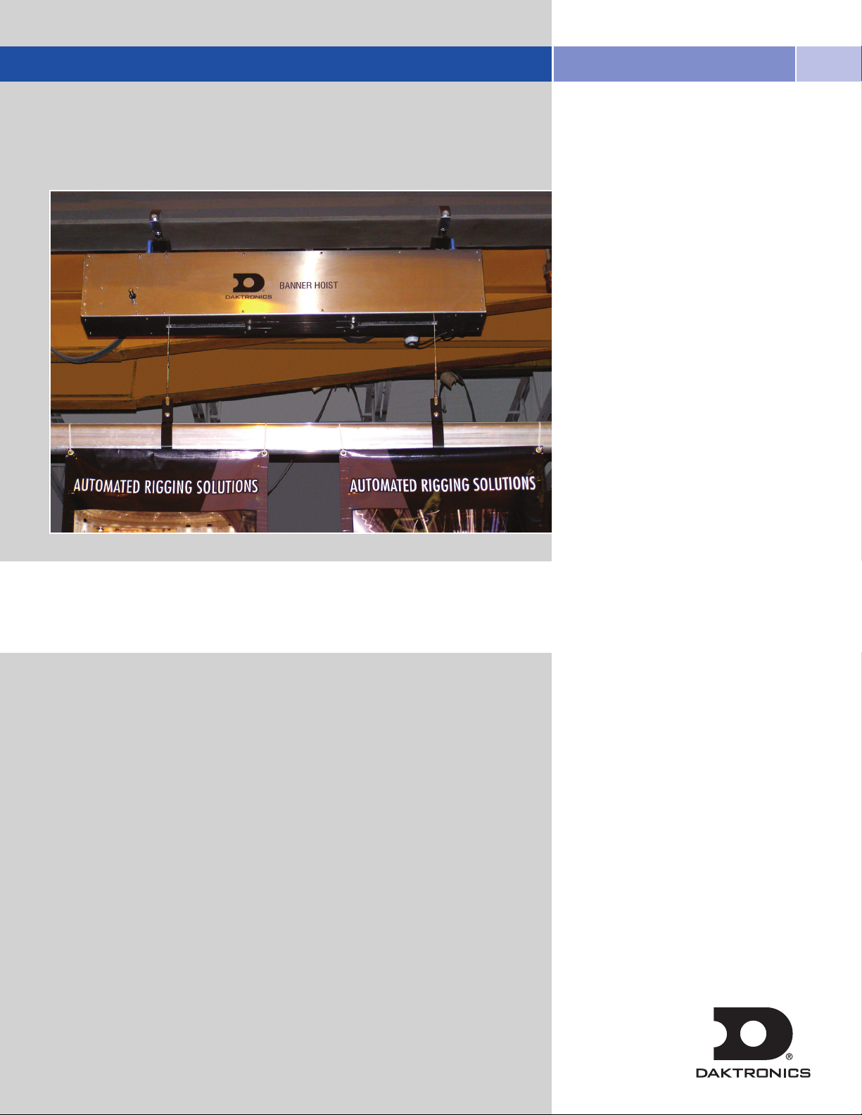
DBH-150 Banner Hoist
Operations & Maintenance Manual
Rev 0 DD1979034 3 June 2011
Page 4

TABLE OF CONTENTS
01 SAFETY INFORMATION 1
02 GENERAL INFORMATION 3
03 GENERAL OPERATION/CONFIGURATION 5
Banner Hoist Remote
Powering On/Off 5
Raising/Lowering 5
Battery Maintenance 5
RF Tuning/Maintenance 6
04 MAINTENANCE/INSPECTION 7
Adjust & Inspect Banner Hoist
DBH-150 Limit Switch Operation & Adjustment 7
Initial Lower Limit Adjustment 8
Initial Upper Limit Adjustment 8
Mechanical Inspection 9
Electrical Inspection 10
Visual Inspection 10
05 WARRANTY INFORMATION 11
i
Page 5
01 SAFETY INFORMATION
Warnings, Cautions, and Notes
All Warning notes contained in this manual indicate information that may endanger personnel.
WARNING
The Daktronics rigging system is designed to raise and lower equipment under the rated hoist capacity ONLY.
Only trained and authorized personnel should be permitted to operate the Daktronics system. The unauthorized use,
alteration, or use for purposes other than those for which it was designed may cause injury to persons, damage to
the equipment, or create conditions which could lead to fatalities. All proper safety considerations must be observed.
While operating the Daktronics rigging system, a spotter must be used in conjunction with the user at all times. The
spotter must have a clear view of all moving elements while maintaining contact with the user. If an unsafe situation occurs, the
spotter must immediately signal the user to halt all movements until the environment is cleared of any person or obstruction.
All installation and maintenance involving the Daktronics drive unit itself or the main electrical control cabinets
will require trained personnel. Simple daily maintenance activities of the workstation may be carried out by the
operators, and in most cases will be all that is needed once installed.
Electrical Safety—General Warning
WARNING
Before working on any of the Daktronics hoists, the main electrical disconnect must be
turned off and locked out according to U.S.A. OSHA regulations 29 CFR 1910.147 or
Australian regulations AS 1418.1 Section 8.10.3.4.
The voltages used in the motor drive and master control panels can cause severe electrical
shock and/or burns. Extreme care is necessary at all times when working with the motor
drives. Only authorized personnel should carry out any installation, commissioning, or
maintenance of the electrical systems. All drive systems have been tuned at the factory
and will not require any additional alteration or adjustment by the owner’s personnel
unless specifically authorized by a Daktronics representative.
SAFETY INFORMATION
1
Page 6

2
Page 7

02 GENERAL INFORMATION
WARNING
The Daktronics hoist system is an automated rigging system, meaning that the load is not counter-weighted. Each
hoist can lift loads only up to the design capacity. Overloading will result in electrical overload protection shut
down of the hoist and possible damage to rigging components.
WARNING
The Daktronics Banner Hoists are not designed to raise and lower people.
These hoists should NEVER be used for this purpose.
The DBH-150 unit must only be used with a maximum load equal to the capacity stated for the
model below. Overloading the system may result in serious injury or an inoperable system
If it is necessary to operate a hoist from a location where the operator's view of the moving
load is obstructed, a second person must be used to observe the load and communicate to
the operator.
Dimensions of DBH-150 Unit
• Averageweightofself-containedhoistmoduleis88lb(39.9kg).
• Height=11.9"(303mm)
• Length=55.1"(1400mm)
•Width=9.9"(251.5mm)
DBH-150 Unit Overview
The Daktronics Banner Hoist is a chain-driven self-contained hoist platform that can be powered using single phase
120V 60Hz or 240V 50Hz electricity. The electricity powers the chain motor which rotates the drums, as well as the
power supply that in turn powers the RF receiver built into the hoist with 24 V DC power. It also controls the operation
of the chain motor and brakes.
The load is raised and lowered by the two available lift lines, utilizing “Zero-Fleet Angle” design architecture to ensure
that the cabling does not wind up on top of itself, protecting the cable and drum from wear.
Control over the unit is performed by utilizing the hand-held RF remote within line of sight of the hoist. It allows the
user to power on/off the unit, raise/lower the lift lines, and remotely program the RF remote to correspond to multiple
receivers, allowing one to control multiple banner hoists at once with one remote simultaneously. The RF remote
requres 2 AA alkaline batteries in order to operate.
GENERAL INFORMATION
3
Page 8

RF Controller
Limit Switch Nylon Drum
Motor Mounting ClipCable GuideElectrical Panel
Drum Chain Drive
Secondary Electric Brake
Drum Cable Keeper
Electrical Panel
Cable Guide Chain Drive
Specifications of DBH-150 Unit
Speed 0-20 ft/min (0.1 m/s)
Gross Lift Capacity 150 lb (68.03 kg)
Maximum Travel Standard travel 60' (18.2 m)
Number of Lift Lines 2 available
Electrical/HP Single Phase, 120V or 240V - 60 or 50HZ
Braking Primary & Secondary brakes are electromechanical type, rated at a minimum 150%
of full load (225 lb / 120.05 kg)
Control Wireless hand-held remote control
Mounting Standard units to be underhung horizontally.
Discuss special mounting requirements with Daktronics.
Cable&Drum 3/32"SteelWireRope
Covers Lightweight aluminum covers are standard for all unit
s
Product dimensions: Length: 55.1" (1400 mm)
Height: 11.9" (303 mm)
Width: 9.9" (251.5 mm)
Crated dimensions: Length: 67" (1702 mm)
Height: 22" (559 mm)
Width: 18" (457 mm)
Weight: 88 lb (39.9 kg)
Component Diagram
4
Page 9

03 GENERAL OPERATION/CONFIGURATION
BANNER HOIST REMOTE
The Banner Hoist System operates using a wireless remote
control that communicates with the hoist using radio wave
RF transmission. When operating the Banner Hoist system,
always have a clear line of sight to the hoist to minimize RF
interference and to promote safe operational use.
Powering On/Off
To power up the Banner Hoist, simply press the green
START button (Figure 1). To power it down, press the
red STOP button.
Raising/Lowering
To raise the Banner Hoist, simply press the UP button
and press the DOWN button.
Battery Maintenance
To replace the two AA alkaline batteries remove the
screw on the plastic back plate using a flat-head screw
Figure 1: Banner Hoist Remote front
driver (Figure 2).
Replace the batteries and screw the back plate into
proper position.
Figure 2: Banner Hoist Remote back
GENERAL OPERATION/CONFIGURATION
5
Page 10

RF Tuning/Maintenance
There are two ways to tune the remote and the hoist
assembly so that they synchronize. The first method is
through reprogramming the remote using the remote
interface plug (Figure 3) in conjunction with the
Copy Module #700PROC pendant (Figure 4) next
to the batteries. The second and less time consuming
method is through using the remote itself next to the
antenna receiver to program the receiver to respond
to the remote’s transmitting signal.
A. To program the receiver to respond to a
specific remote, first ensure the remote and
receiver are of the same model, and
operate on the same frequency band by
opening up the remote and receiver and
ensuring their frequency crystals match.
B. Place the remote as close as possible to the
receiver to avoid unnecessary interference.
C. Turn off the receiver’s power supply, then turn
it back on. Because the receiver is fed power
through the hoist itself, turn the hoist
assembly on and off.
D. Within 4 minutes of turning the Daktronics
Banner Hoist back on, press and hold the
STOP button. Continue holding and then press
and hold the DOWN button. While holding
the previous two buttons press the UP button
4 times, and release all the buttons when the
red LED light on the remote flashes. If done
correctly the remote and receiver on the hoist
should be synchronized.
E. It is possible to program multiple hoist receivers
to respond to one remote I.D. through this
programming method.
F. If the remote programming data has become
corrupt or access to the hoist receiver for
optimal remote synchronization is restricted, use
of the Copy Module #700PROC can allows
copying the programming data of one remote
into another remote, allowing that remote to
work with the equipment the source remote
is programmed to work with. (Copy Module
#700PROC sold optionally.)
G. If problems continue with the remote and/or the
receiver on the hoist, consult with Daktronics,
see manufacturing contact on the inside cover
of this manual.
Figure 3: Banner Hoist Remote Interface Plug
Figure 4: Copy Module #700PROC
6
Page 11

04 MAINTENANCE/INSPECTION
Figure 5: Rotary Limit Switch
Lower Overtravel
Limit Switch
Lower Normal
Limit Switch
Upper Normal
Limit Switch
Upper Overtravel
Limit Switch
ADJUST & INSPECT BANNER HOIST
After installation under normal circumstances, users
should never have to physically move the hoist assembly
or open it up for maintenance. It may become necessary
though to open up the side casing and check the cables
on the drum should they begin to run over themselves.
If the upper and lower limits of travel need changing,
it is necessary to open the smaller side panel near the
receiver antenna to gain access to the rotary limit switch.
DBH-150 Limit Switch Operation & Adjustment
The limit switch assembly is comprised of a fully enclosed
4-switch rotary mechanism attached to the hoist drum
shaft with a flexible coupling. As the drum shaft turns,
the switch mechanism rotates cams in one direction or
the other to actuate snap action switches by depressing
roller levers attached to each switch.
The upper and lower limits, both normal and over-travel,
are set from the factory for the maximum travel of the
hoist. After installation, it may be necessary to reset
these limits based on the height of the installation and
the desired travel distance. The limit switch assembly is
shown in Figure 5 and is located under the left most
front panel of the hoist where the wireless receiver
antenna protrudes. Remove this panel to gain access to
the limit switch assembly. It will be necessary to remove
the yellow plastic cover to make the switch adjustments.
As shown on Figure 6, the Rotary Limit Switch is
comprised of a Lower Over-travel Limit Switch, a Lower
Normal Limit Switch, an Upper Normal Limit Switch,
and an Upper Over-travel Limit Switch. The limit switches
are activated when the white cam wheel rotates into the
roller lever on the limit switch.
Figure 6: Rotary Limit Switch without cover
MAINTENANCE/INSPECTION
7
Page 12

Initial Lower Limit Adjustment
To initially adjust the lower limits, start by lowering the hoist
to the desired low limit height. Adjust the lower normal cam
wheel by turning the yellow set screw associated with the lower
normal limit switch (Figure 7) counterclockwise until it contacts
the back side of the roller lever on the switch, and actuates the
switch. Operate the hoist up and down into the limit to test.
Re-adjust the switch as necessary by rotating the yellow set screw
counterclockwise to raise the limit or clockwise to lower the limit.
Turning the adjustment screw ¼ turn will change the limit by
approximately9"(230mm).
Continue by setting the lower over-travel limit. Operate the hoist
until it actuates the lower normal limit and stops. Adjust the
lower over-travel cam wheel by rotating the yellow set screw
counterclockwise until it actuates the lower over-travel switch.
With the hoist power on and the hoist enabled from the remote
control, the main contactor (LC1) will de-energize. Once the
switch is actuated turn the yellow set screw ¼ turn clockwise.
The switch will deactivate and the main contactor will energize.
Thiswillgiveapproximately6"(150mm)ofover-traveldistance
beyond the normal lower limit.
Lower Overtravel
Limit Switch
Lower Normal
Limit Switch
Upper Normal
Limit Switch
Upper Overtravel
Limit Switch
Initial Upper Limit Adjustment
To initially adjust the upper limits, start by raising the hoist to the
desired high limit height. Adjust the upper normal cam wheel by
turning the yellow set screw associated with the upper normal
limit switch (Figure 7) clockwise until it contacts the front side of
the roller lever on the switch, and actuates the switch. Operate
the hoist up and down into the limit to test. Re-adjust the switch
as necessary by rotating the yellow set screw counterclockwise
to raise the limit or clockwise to lower the limit. Turning the
adjustment screw ¼ turn will change the limit by approximately
9"(230mm).Figure 8 illustrates the labels corresponding to
each screw.
Continue by setting the upper over-travel limit. Operate the hoist
until it actuates the upper normal limit and stops. Adjust the
upper over-travel cam wheel by rotating the yellow set screw
clockwise until it actuates the lower over-travel switch. With the
hoist power on and the hoist enabled from the remote control,
the main contactor (LC1) will de-energize. Once the switch is
actuated, turn the yellow set screw ¼ turn counterclockwise. The
switch should deactivate and the main contactor will energize.
Thiswillgiveapproximately6"(150mm)ofover-traveldistance
beyond the normal upper limit.
Once the limit switches are set, under normal operating
conditions they should not have to be reset. If the hoist is moved,
or the high or low limits do need to be reset for any reason, do
so by using the procedures above. When readjusting the limits,
make certain to reset the over-travel limits as well.
Figure 7: Adjustment Screw location
The upper cams will activate the
switches from the near side and the
lower cams will activate the switches
from the far side as shown.
LIMIT SWITCH INFORMATION TABLE
Limit Switch
Model
FRS-100 90 9 in. 228.6 mm
8
Set Screw
Turn Degree
Limit Change
Distance(")
Limit Change
Distance (mm)
Figure 8: Rotary Limit Switch Wire labels
Page 13

Figure 10:
Drive Chain
Figure 13: Cable Drum with Plastic Feed Guide
Figure 14: Cable Chain Clip
Figure 11:
Cable Guide
Chain A
Figure 12:
Cable Guide
Chain B
MECHANICAL INSPECTION
Inspection Schedule
Mechanical and electrical inspections shall be completed
in accordance with local regulations or every 5 years,
whichever comes sooner. Inspections shall be completed
by a competent person who is certified for field service.
All repairs shall also be inspected nd approved by a
competent person who is certified for field service prior
to the hoist being returned to service.
After usage over long periods of time, certain parts of
the Banner Hoist Assembly may become more audible
as certain components require periodical lubrication.
Examples of these parts of the assembly that could
end up requiring such inspection and maintenance
are shown on the illustrations to the left. Take into
consideration the environment of where the Banner Hoist
assembly will be installed to reduce the likelihood of
wear. On chain drives and acme parts, white lithium
grease should be used to lubricate (refer to
Figures 10-12).
Always ensure that when operating and performing
maintenance/inspection on the Banner Hoist system
that there is at least enough weight on the cables to
keep them taut. If the cables are allowed to become
slackened, the cable may become unwound from
the drum or for the cable to cross-over itself. Both
of these conditions present a safety hazard and will
depreciate the life of both the cable and the drum.
If a situation occurs where the cable has run over
the drum, simply lower the hoist to its lower limit and
pull the cabling outward, ensuring that the cabling
left on the drum is in line. Then with weight applied
raise the hoist to correctly rewind the cabling. Also
ensure that the cable is being correctly guided
through the Plastic Feed Guide (Figures 13,14)
while performing the rewinding. It may be necessary
to remove the front panel of the hoist to ensure
the cable is wound correctly on the drum. Should
additional problems or questions occur, do not
hesitate to call Daktronics for additional support.
Positioning of Drum Cable Keepers
Verify that the drum cable keepers are positioned
correctly as shown in Figure 15. The assemblies should
run parallel with the drum and contact the cables to
keep them in the drum grooves. If the plastic keeper part
is out of position, it should be relocated as shown. The
plastic keeper part is spring applied and should be free
to come off the drum. Lift the ends off the drum to ensure
the springs and resulting assembly are not binding.
Figure 15: Drum Cable keepers
MAINTENANCE/INSPECTION
9
Page 14

ELECTRICAL INSPECTION
Under normal conditions, the Daktronics Banner Hoist should
provide years of maintenance free service. Daktronics recommends
periodic electrical inspections for corrosion and wear, particularly
in high temperature and/or high humidity environments. Should
issues occur or if the hoist is exposed to water or other fluids,
immediately disconnect incoming power and contact Daktronics for
technical assistance.
Figure 16 shows the proper wiring for the Banner Hoist power
panel. If electrical issues are observed, this is where technical
assistance will focus.
Figure 17 displays the Banner Hoist RF Receiver and the
schematic of the wiring in the power panel in Figure 16 which
will be used as a reference when receiving technical assistance.
VISUAL INSPECTION
A quick visual inspection can provide valuable information about
how the hoist is operating and whether further maintenance is
required. Periodical visual inspections should be completed in
between scheduled maintenance inspections.
When visually inspecting the hoist, look for components that
have become loose or possible failures such as cracking in the
metal framework or other components. In addition, check for the
following:
· Cables should be tight around the drum, in the correct grooves
and not overlapping
· Cables should follow the correct path from the drum through the
cable guide assembly
· Chains are fitted properly around the sprockets
· Adequate lubrication on the chains and acme screw parts
· Intact wire terminations
· No frayed wires
· No visible corrosion or wear on or around the electrical
components
Figure 16: Banner Hoist Power Panel
10
Figure 17: Banner Hoist RF Receiver
Page 15

05 WARRANTY
This Warranty and Limitation of Liability (the “Warranty”) sets forth the warranty provided by Daktronics with respect to the
Equipment. By accepting delivery of the Equipment, Purchaser agrees to be bound by and accept these terms and conditions.
All defined terms within the Warranty shall have the same meaning and definition as provided elsewhere in the Agreement.
DAKTRONICS WILL ONLY BE OBLIGATED TO HONOR THE WARRANTY SET FORTH IN THESE TERMS AND CONDITIONS
UPON RECEIPT OF FULL PAYMENT FOR THE EQUIPMENT.
1. Warranty Coverage
A. Daktronics warrants to the original end-user that the Equipment will be free from Defects (as defined below) in materials and
workmanship for a period of one (1) year (the “Warranty Period”). The warranty period shall commence on the earlier of: (i)
four weeks from the date that the equipment leaves Daktronics’ facility; or (ii) Substantial Completion as defined herein. The
warranty period shall expire on the first anniversary of the commencement date.
“Substantial Completion” means the operational availability of the Equipment to the Purchaser in accordance with the
Equipment’s specifications, without regard to punch-list items, or other non-substantial items which do not affect the operation of
the Equipment.
B. Daktronics’ obligation under this Warranty is limited to, at Daktronics’ option, replacing or repairing, any Equipment or part
thereof that is found by Daktronics not to conform to the Equipment’s specifications. Unless otherwise directed by Daktronics,
any defective part or component shall be returned to Daktronics for repair or replacement. Daktronics may, at its option,
provide on-site warranty service. Daktronics shall have a reasonable period of time to make such replacements or repairs and
all labor associated therewith shall be performed during regular working hours. Regular working hours are Monday through
Friday between 8:00 a.m. and 5:00 p.m. at the location where labor is performed, excluding any holidays observed by either
Purchaser or Daktronics.
C. Daktronics shall pay ground transportation charges for the return of any defective component of the Equipment. If returned
Equipment is repaired or replaced under the terms of this warranty, Daktronics will prepay ground transportation charges back
to Purchaser; otherwise, Purchaser shall pay transportation charges to return the Equipment back to the Purchaser. All returns
must be pre-approved by Daktronics before shipment. Daktronics shall not be obligated to pay freight for any unapproved
return. Purchaser shall pay any upgraded or expedited transportation charges.
D. Any replacement parts or Equipment will be new or serviceably used, comparable in function and performance to the
original part or Equipment, and warranted for the remainder of the Warranty Period. Purchasing additional parts or Equipment
from the Seller does not extend this Warranty Period.
E. Defects shall be defined as follows. With regard to the Equipment (excepting LEDs), a “Defect” shall refer to a material
variance from the design specifications that prohibit the Equipment from operating for its intended use. With respect to LEDs,
“Defects” are defined as LED pixels that cease to emit light. The limited warranty provided by Daktronics does not impose any
duty or liability upon Daktronics for partial LED pixel degradation. Nor does the limited warranty provide for the replacement
or installation of communication methods including but not limited to, wire, fiber optic cable, conduit, trenching, or for the
purpose of overcoming local site interference radio equipment substitutions.
WARRANTY
11
Page 16

THIS LIMITED WARRANTY IS THE ONLY WARRANTY APPLICABLE TO THE EQUIPMENT AND REPLACES ALL
OTHER WARRANTIES OR CONDITIONS, EXPRESS OR IMPLIED, INCLUDING, BUT NOT LIMITED TO, THE
IMPLIED WARRANTIES OR CONDITIONS OF MERCHANTABILITY AND FITNESS FOR A PARTICULAR PURPOSE.
SPECIFICALLY, EXCEPT AS PROVIDED HEREIN, THE SELLER UNDERTAKES NO RESPONSIBILITY FOR THE QUALITY
OF THE EQUIPMENT OR THAT THE EQUIPMENT WILL BE FIT FOR ANY PARTICULAR PURPOSE FOR WHICH
PURCHASER MAY BE BUYING THE EQUIPMENT. ANY IMPLIED WARRANTY IS LIMITED IN DURATION TO THE
WARRANTY PERIOD. NO ORAL OR WRITTEN INFORMATION, OR ADVICE GIVEN BY THE COMPANY, ITS
AGENTS OR EMPLOYEES, SHALL CREATE A WARRANTY OR IN ANY WAY INCREASE THE SCOPE OF THIS
LIMITED WARRANTY.
THIS LIMITED WARRANTY IS NOT TRANSFERABLE.
2. Exclusion from Warranty Coverage
The limited warranty provided by Daktronics does not impose any duty or liability upon Daktronics for:
A Any damage occurring, at any time, during shipment of Equipment unless otherwise provided for in the
Agreement. When returning Equipment to Daktronics for repair or replacement, Purchaser assumes all risk of loss or
damage, and agrees to use any shipping containers that might be provided by Daktronics and to ship the Equipment
in the manner prescribed by Daktronics;
B. Any damage caused by the unauthorized adjustment, repair or service of the Equipment by anyone other than
personnel of Daktronics or its authorized repair agents;
C. Damage caused by the failure to provide a continuously suitable environment, including, but not limited to: (i)
neglect or misuse, (ii) a failure or sudden surge of electrical power, (iii) improper air conditioning or humidity control,
or (iv) any other cause other than ordinary use;
D. Damage caused by fire, flood, earthquake, water, wind, lightning or other natural disaster, strike, inability to
obtain materials or utilities, war, terrorism, civil disturbance or any other cause beyond Daktronics’ reasonable
control;
E. Failure to adjust, repair or replace any item of Equipment if it would be impractical for Daktronics personnel to
do so because of connection of the Equipment by mechanical or electrical means to another device not supplied
by Daktronics, or the existence of general environmental conditions at the site that pose a danger to Daktronics
personnel;
F. Any statements made about the product by salesmen, dealers, distributors or agents, unless such statements are in
a written document signed by an officer of Daktronics. Such statements as are not included in a signed writing do not
constitute warranties, shall not be relied upon by Purchaser and are not part of the contract of sale;
G. Any damage arising from the use of Daktronics products in any application other than the commercial and
industrial applications for which they are intended, unless, upon request, such use is specifically approved in writing
by Daktronics; or
H. Any performance of preventive maintenance.
3. Limitation of Liability
Daktronics shall be under no obligation to furnish continued service under this Warranty if alterations are made to the
Equipment without the prior written approval of Daktronics.
It is specifically agreed that the price of the Equipment is based upon the following limitation of liability. In no event
shall Daktronics (including its subsidiaries, affiliates, officers, directors, employees, or agents) be liable for any
12
Page 17

special, consequential, incidental or exemplary damages arising out of or in any way connected with the Equipment or otherwise,
including but not limited to damages for lost profits, cost of substitute or replacement equipment, down time, lost data, injury to
property or any damages or sums paid by Purchaser to third parties, even if Daktronics has been advised of the possibility of such
damages. The foregoing limitation of liability shall apply whether any claim is based upon principles of contract, tort or statutory
duty, principles of indemnity or contribution, or otherwise.
In no event shall Daktronics be liable to Purchaser or any other party for loss, damage, or injury of any kind or nature arising
out of or in connection with this Warranty in excess of the purchase price of the Equipment actually delivered to and paid for by
the Purchaser. The Purchaser’s remedy in any dispute under this Warranty shall be ultimately limited to the Purchase Price of the
Equipment to the extent the Purchase Price has been paid.
4. Assignment of Rights
The Warranty contained herein extends only to the original end-user (which may be the Purchaser) of the Equipment and no
attempt to extend the Warranty to any subsequent user-transferee of the Equipment shall be valid or enforceable without the
express written consent of Daktronics.
5. Dispute Resolution
Any dispute between the parties will be resolved exclusively and finally by arbitration administered by the American Arbitration
Association (“AAA”) and conducted under its rules, except as otherwise provided below. The arbitration will be conducted
before a single arbitrator. The arbitration shall be held in Brookings, South Dakota. Any decision rendered in such arbitration
proceedings will be final and binding on each of the parties, and judgment may be entered thereon in any court of competent
jurisdiction. This arbitration agreement is made pursuant to a transaction involving interstate commerce, and shall be governed by
the Federal Arbitration Act.
6. Governing Law
The rights and obligations of the parties under this warranty shall not be governed by the provisions of the United Nations
Convention on Contracts for the International Sales of Goods of 1980. Both parties consent to the application of the laws of the
State of South Dakota to govern, interpret, and enforce all of Purchaser and Daktronics rights, duties, and obligations arising from,
or relating in any manner to, the subject matter of this Warranty, without regard to conflict of law principles.
7. Availability of Extended Service Agreement
For Purchaser’s protection, in addition to that afforded by the warranties set forth herein, Purchaser may purchase extended
warranty services to cover the Equipment. The Extended Service Agreement, available from Daktronics, provides for electronic
parts repair and/or on-site labor for an extended period from the date of expiration of this warranty. Alternatively, an Extended
Service Agreement may be purchased in conjunction with this warranty for extended additional services. For further information,
contact Daktronics Customer Support at 1-800-DAKTRONICS (1-800-325-8766).
WARRANTY
13
Page 18

Page 19

Daktronics
7200 Rawson Road Victor, New York 14564 USA
tel 866-486-7835 585-924-5000 fax 585-924-0545
www.daktronics.com/rigging email sales@daktronics.com
Copyright © 2011 Daktronics DD11979034 REV 0 3 June 2011
 Loading...