

Page 1
Data Time® Series 50
Time & Temperature Displays
Installation, Operation &
Maintenance Manual
ED-7207
Data Time is a registered trademark of Daktronics, Inc.
ED 7207
Product #1114
Rev. 10 - 2Apr98
Copyright 1994 Daktronics, Inc.
All rights reserved. While every
precaution has been taken in the
preparation of this manual, the publisher
assumes no responsibility for errors or
omissions. No part of this book covered
by the copyrights hereon may be
reproduced or copied in any form or by
any means - graphic, electronic, or
mechanical, including photocopying,
taping, or information storage and
retrieval systems - without written
permission of the publisher.
DAKTRONICS, INC.
Setting New Standards Worldwide
P.O. Box 5128 331 32nd Ave. Brookings, SD 57006
Phone (605)697-4400 or (800) 843-9879 Fax 697-4700
Page 2

Page 3

REPRODUCTION REFERENCE
ED7207 – P1114
Data Time Series 50 Time and Temperature
1) This page is for reproduction reference only and will not be included in the manual.
2) This manual is to be copied on FRONT AND BACK PAGES -8 ½ x 11 paper.
Note: The first page, Cover Page, uses the front of the page (blank on back). Section
heading pages always start on a new page; they never start on the back of another page.
3) Drawings included in this manual:
Section 1: A-61929, A-56629, A-57794, A-59698, A-58669, A-63117
Section 2: A-72324, A-72325, A-72326
Section 3: A-15267, A-57279, A-57319, A-67341, A-87841
Section 4: A-57210
Section 5: A-37070, A-67339
Appendix A: A -59425, A-87845
Appendix B: A-65383
Appendix C: None
Appendix D: B-99250 (printed as an A-size)
4) Use a blue window cover and a blue back.
5) Punch all pages, window cover and back cover along the left edge and bind with a binder.
6) Please direct questions and suggestions to Engineering Secretarial.
Page 4

Page 5

Table of Contents
1. Introduction............................................................................................................... 1-1
1.1 How To Use This Manual................................................................................... 1-1
1.2 Display Overview............................................................................................... 1-1
2. Mechanical Installation ............................................................................................ 2-1
2.1 Display Definitions.............................................................................................. 2-1
2.2 Support Column Selection ....................................................................................2-1
2.3 Mounting Details .................................................................................................2-1
3. Electrical Installation................................................................................................ 3-1
3.1 Display Access................................................................................................... 3-1
3.2 Power Connection .............................................................................................. 3-2
3.3 Grounding........................................................................................................... 3-2
3.4 Handset Connection ............................................................................................3-3
3.5 Temperature Sensor/Light Detector ..................................................................... 3-3
3.5.1 Eave Mounting of Sensor ........................................................................ 3-4
3.5.2 Connection to Controller ..........................................................................3-4
3.6 Master/Slave Connection..................................................................................... 3-4
3.6.1 12”, 18”, 24” and 36” Displays ................................................................ 3-4
3.6.2 48” and 60” Displays .............................................................................. 3-5
4. Operation................................................................................................................... 4-1
4.1 Using the Handset to Program the Controller ........................................................4-1
4.2 Setting the Time ..................................................................................................4-1
4.3 Setting the Functions ........................................................................................... 4-2
4.4 The 14 Display Functions .................................................................................... 4-2
4.6 Setting the Price Values...................................................................................... 4-7
4.7 Operation without Temperature Sensor/Light Detector.......................................... 4-8
4.8 Switch Settings ................................................................................................... 4-8
5. Maintenance & Troubleshooting............................................................................5-1
5.1 The Lamp Driver ................................................................................................5-2
5.2 The Display Controller ........................................................................................ 5-3
5.2.1 Connectors............................................................................................. 5-4
5.2.2 Switches ................................................................................................ 5-4
5.2.3 Status Indicators..................................................................................... 5-5
5.3 Troubleshooting .................................................................................................. 5-5
5.3.1 Power-Up Tests..................................................................................... 5-6
5.3.2 Controller Lamp Test.............................................................................. 5-6
Table of Contents
i
Page 6

5.3.3 Lamp Driver Test................................................................................... 5-7
5.3.4 Time and Temperature ............................................................................5-7
5.3.5 Dimming ................................................................................................ 5-7
5.4 Repair................................................................................................................ 5-7
5.4.1 Fuse Replacement .................................................................................. 5-8
5.4.2 Exchanging a Controller .......................................................................... 5-8
5.4.3 Exchanging a Lamp Driver ......................................................................5-8
5.4.4 Replacing Triacs .....................................................................................5-9
5.5 Structural Inspection ........................................................................................... 5-9
5.6 Replacement Parts List....................................................................................... 5-9
5.7 Unit Exchange/Replacement Procedure ............................................................... 5-9
Appendix A: Optional Indoor Controller Console .......................................................A-1
A.1 Controller Location ............................................................................................ A-1
A.2 Installation/Signal Connection.............................................................................. A-1
A.3 Indoor Console Operation ...................................................................................A-2
A.4 Troubleshooting ................................................................................................. A-4
A.5 Parts for Indoor Control Option........................................................................... A-4
Appendix B: Full View Option.........................................................................................B-1
Appendix C: Update Data Time I....................................................................................C-1
C.1 Introduction.......................................................................................................C-1
C.2 Installation.........................................................................................................C-1
C.3 Operation..........................................................................................................C-1
C.4 Troubleshooting .................................................................................................C-1
C.5 Replacement Parts.............................................................................................C-1
Appendix D: Update Triac Time & Temperature .........................................................D-1
D.1 Installation......................................................................................................... D-1
D.1.1 Triac Controller Chassis Removal........................................................... D-1
D.1.2 Display Driver Assembly Installation .......................................................D-1
D.1.3 Controller Installation ............................................................................. D-4
D.1.4 Temperature/Light Sensor Installation ..................................................... D-5
D.2 Operation.......................................................................................................... D-5
D.3 Troubleshooting ................................................................................................. D-5
D.4 Replacement Parts............................................................................................. D-5
ii
Table of Contents
Page 7

List of Figures
Figure 1: Installation Electrical Layout......................................................................................3-1
Figure 2: Handset and Enclosure..............................................................................................3-3
Figure 3: Block Diagram/Component Layout.............................................................................5-1
Figure 4: Dot Matrix Digit Segmentation for 18", 24", 36"...........................................................5-3
Figure 5: Installation Electrical Layout - Indoor Controller.........................................................A-4
Figure 6: Data Time 50 Controller Connections ........................................................................C-2
Figure 7: Time & Temp. Enclosure..........................................................................................D-2
Figure 8: Connections from Controller......................................................................................D-4
List of Figures
iii
Page 8

Page 9
SECTION 1 : Introduction
1.1 How To Use This Manual
This manual explains the installation, operation and maintenance of Daktronics Data Time
Series 50 Incandescent Time and Temperature Displays. It provides dimensions and guides
you in mounting, wiring and operating these displays. The manual is divided into mechanical,
electrical, operation and maintenance sections.
For additional questions regarding the safety, installation, operation or service of these displays,
please refer to the phone numbers listed on the cover page of this manual.
KImportant Safeguards:
1. Read and understand these instructions before installing.
2. Do not drop the control console or allow it to get wet.
3. Be sure the display is properly grounded.
4. Disconnect power to the displays when they are not in use.
5. Disconnect power when servicing the displays.
6. Do not modify the displays or attach any panels or coverings to the displays
without the written consent of Daktronics, Inc.
The box below is an illustration of Daktronics drawing numbering system. The drawing
number “7087-P08A-69945” is how Daktronics identifies individual drawings. This number is
located in the lower right corner of the drawing. The manual refers to drawings by the last
five digits and the letter preceding them. In the example below, the drawing would be referred
to as Drawing A-69945. Each set of reference drawings will be inserted at the end of the
section which first references them.
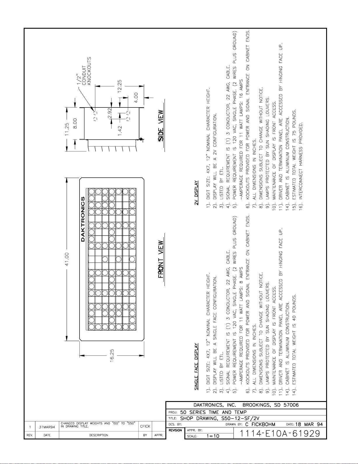
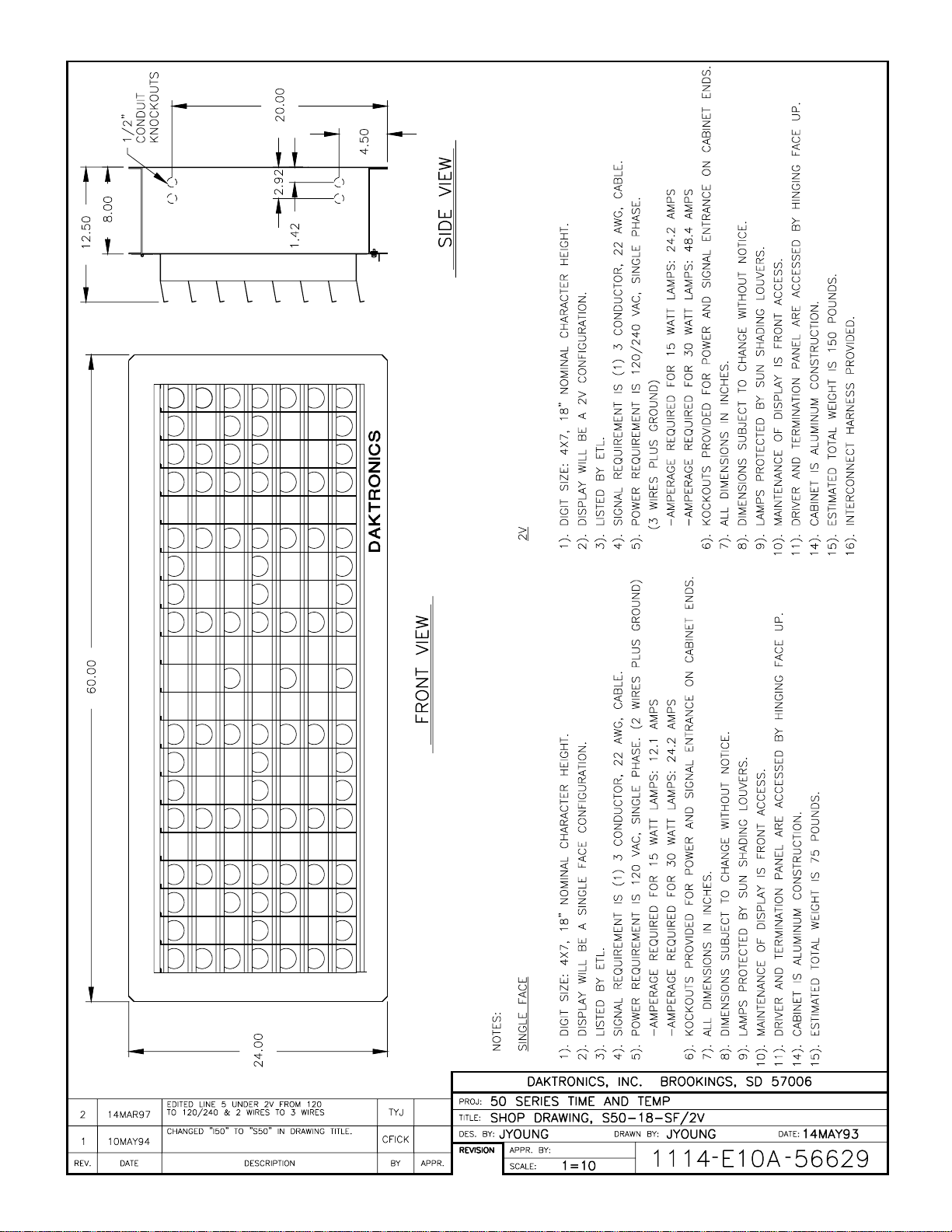
1.2 Display Overview
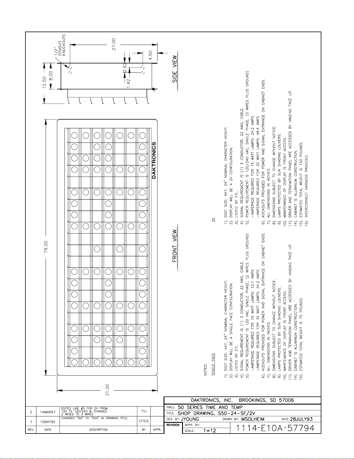
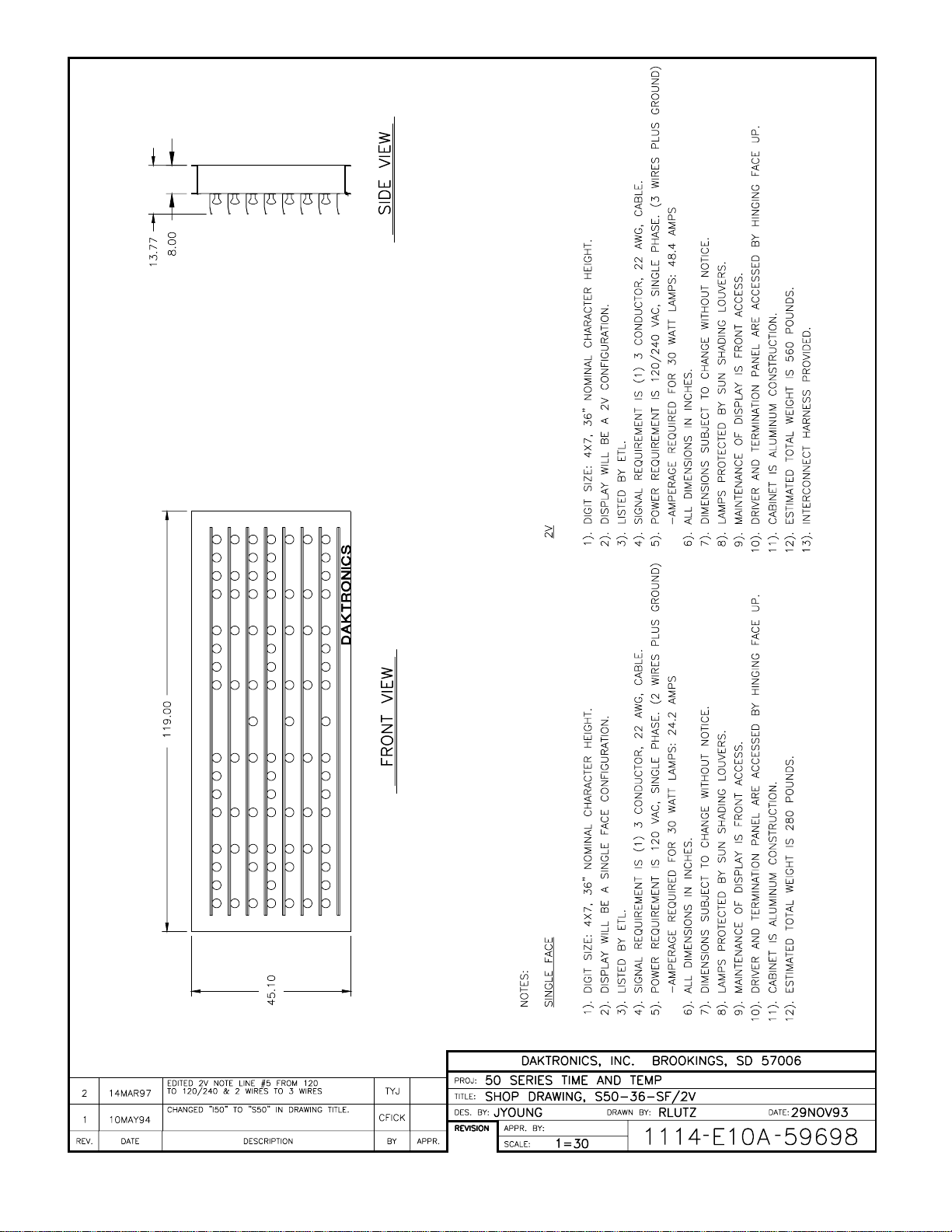
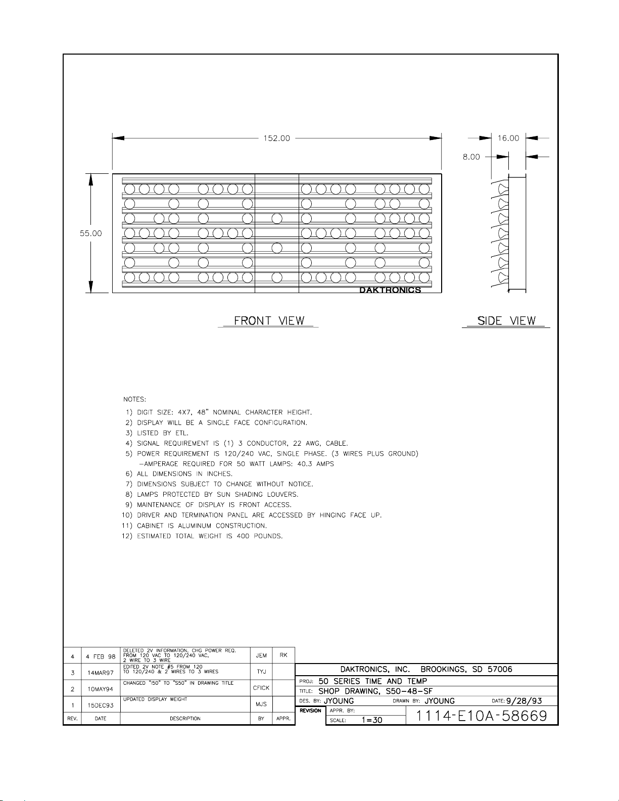
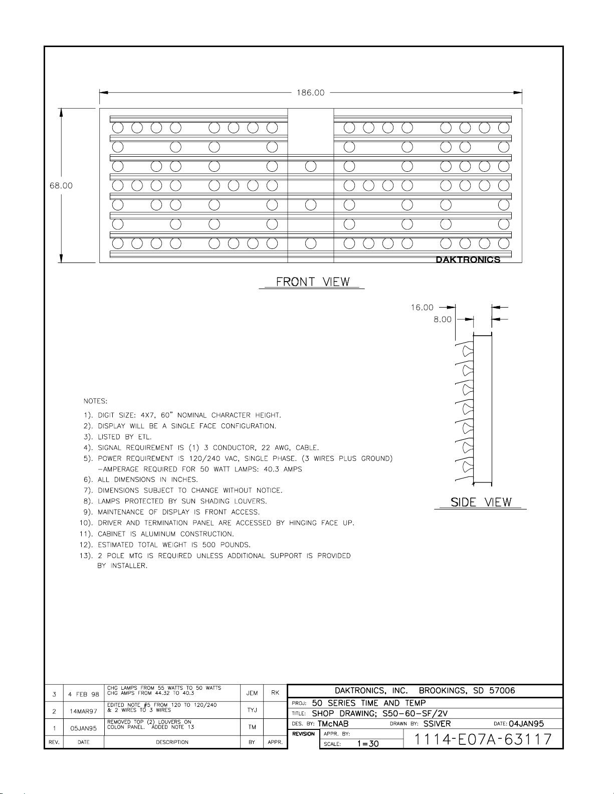
Reference Drawings: Shop Drawing, S50-12-SF/2V.............Drawing A-61929
Shop Drawing, S50-18-SF/2V .............Drawing A-56629
Shop Drawing, S50-24-SF-2V............Drawing A-57794
Shop Drawing, S50-36-SF/2V .............Drawing A-59698
Shop Drawing, S50-48-SF..................Drawing A-58669
Shop Drawing, S50-60-SF..................Drawing A-63117
Refer to the following drawings for overall display specifications for single face and 2V
displays, and mounting details. Also use these drawings as an aid for mechanical installation,
electrical installation and maintenance.
Introduction
1-1
Page 10

1-2
DATA TIME® SERIES 50 INTRODUCTION
TIME & TEMP DISPLAYS
Page 11
Page 12
Page 13
Page 14
Page 15
Page 16
Page 17

SECTION 2 : Mechanical Installation
2.1 Display Definitions
Two configurations of displays are offered: single face displays and 2V displays. A single face
display is a single-sided, stand-alone unit. A 2V display consists of two units – one master and
one slave. The two sides of this display may be mounted at any angle between 0 and 180
degrees. When mounted back-to-back, the maximum distance between displays cannot
exceed 24”. The interconnect harness for the slave unit is coiled up inside the cabinet of the
slave unit.
48” and 60” displays do not have the 24” maximum separation limitation. 48” and 60” displays
do not have the master/slave interconnect, only a controller signal cable.
2.2 Support Column Selection
Support column size is dependent on the height and total wind loading of the display and
advertising panels that make up the entire display. Column selection is critical and should be
done only by a qualified individual. Only pipe and square or rectangular tubing are
recommended for single column displays. Wide flange members have low torque resisting
properties and wind flutter may result. It is the responsibility of the insta ller to determine the
column size required to support all the components to be mounted.
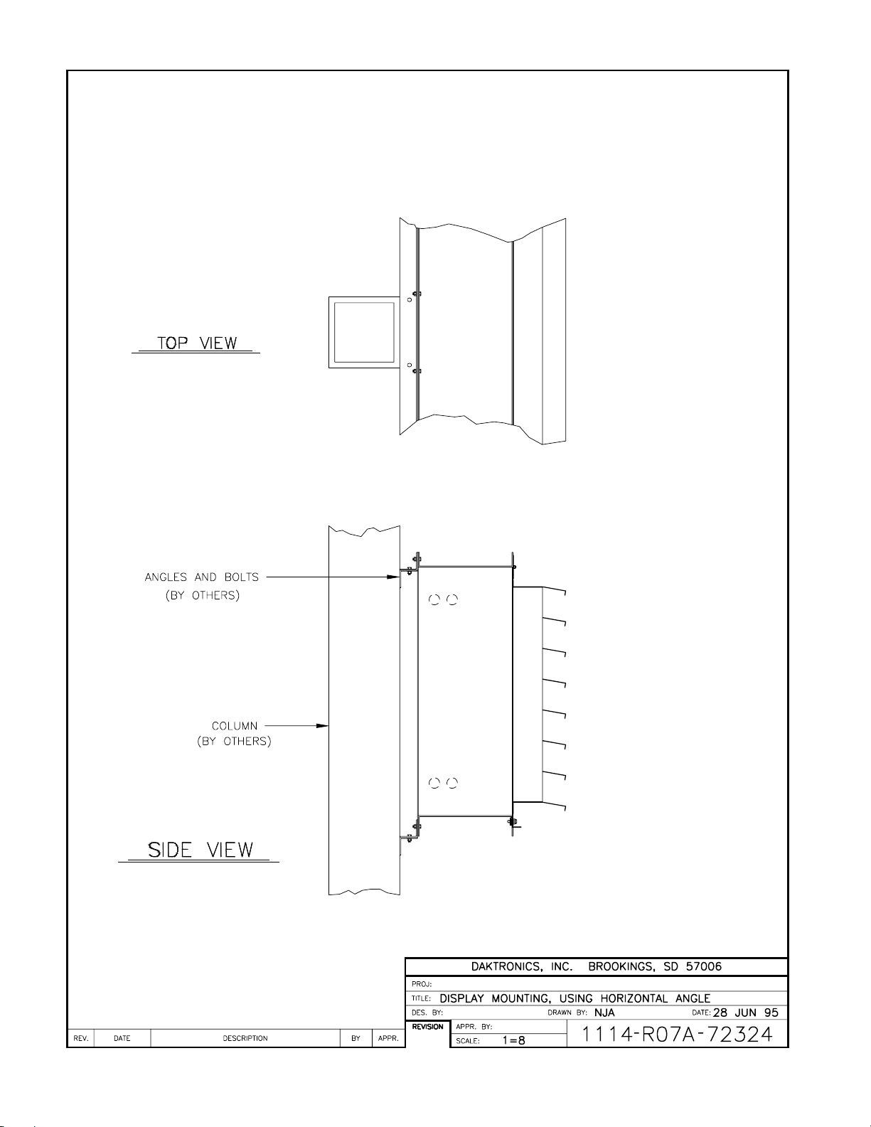
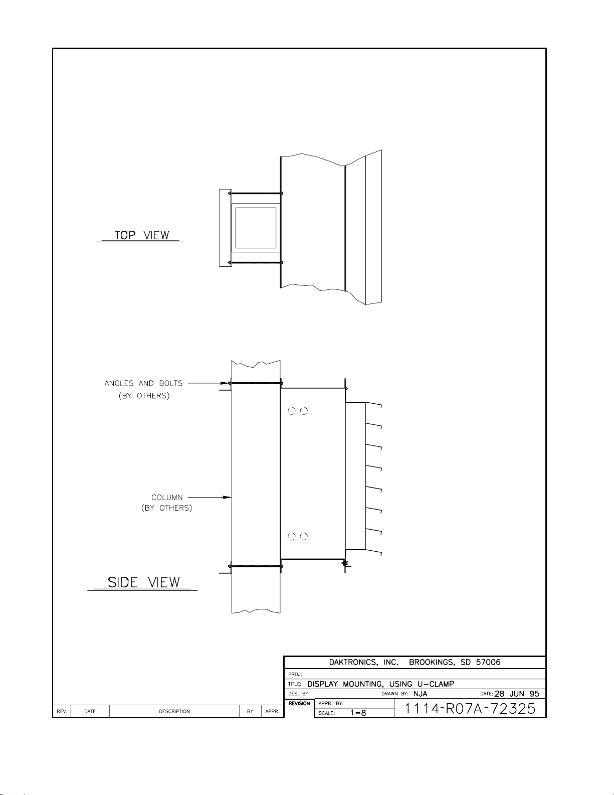
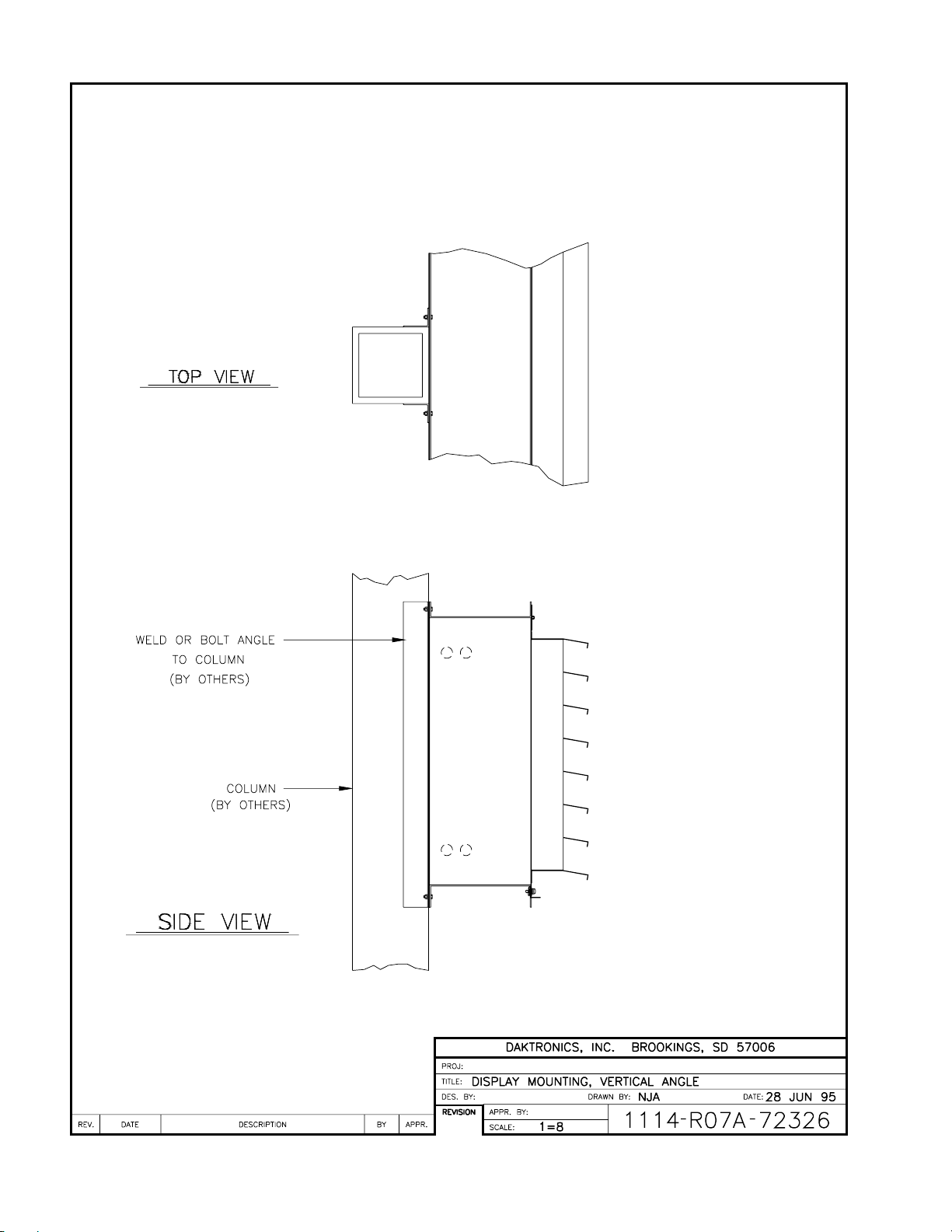
2.3 Mounting Details
Reference Drawings: Display Mounting, Using Horizontal Angle.....Drawing A-72324
Display Mounting, Using U-Clamp................Drawing A-72325
Display Mounting, Vertical Angle...................Drawing A-72326
Drawings A-72324, A-72325 and A-72326 show suggested methods of mounting the
displays to columns. The display cabinet has a 1.25” external flange. It is the responsibility of
the installer to ensure the installation will adequately meet local standards. The mounting
hardware and method are also the responsibility of the installer. Any aluminum angle used for
mounting should be a minimum of 1/4” thick. Refer to the appropriate drawing in Section 1
for additional mounting details.
60” displays require a two (2) column mounting method unless additional horizontal support is
provided by the customer. Minimum center to center column spacing is 72”. Engineering of
additional support is the responsibility of the customer.
Mechanical
Installation
2-1
Page 18

Page 19
Page 20
Page 21
Page 22

Page 23
SECTION 3 : Electrical Installation
(50 ft maximum)
Reference Drawings: Eave Mounting of Sensor.........................................Drawing A-15267
Assembly, Term Plate..............................................Drawing A-57279
System Schematic...................................................Drawing A-57319
Schematic, 48” & 60” T&T.......................................Drawing A-67341
Component Access and Controller..........................Drawing A-87841
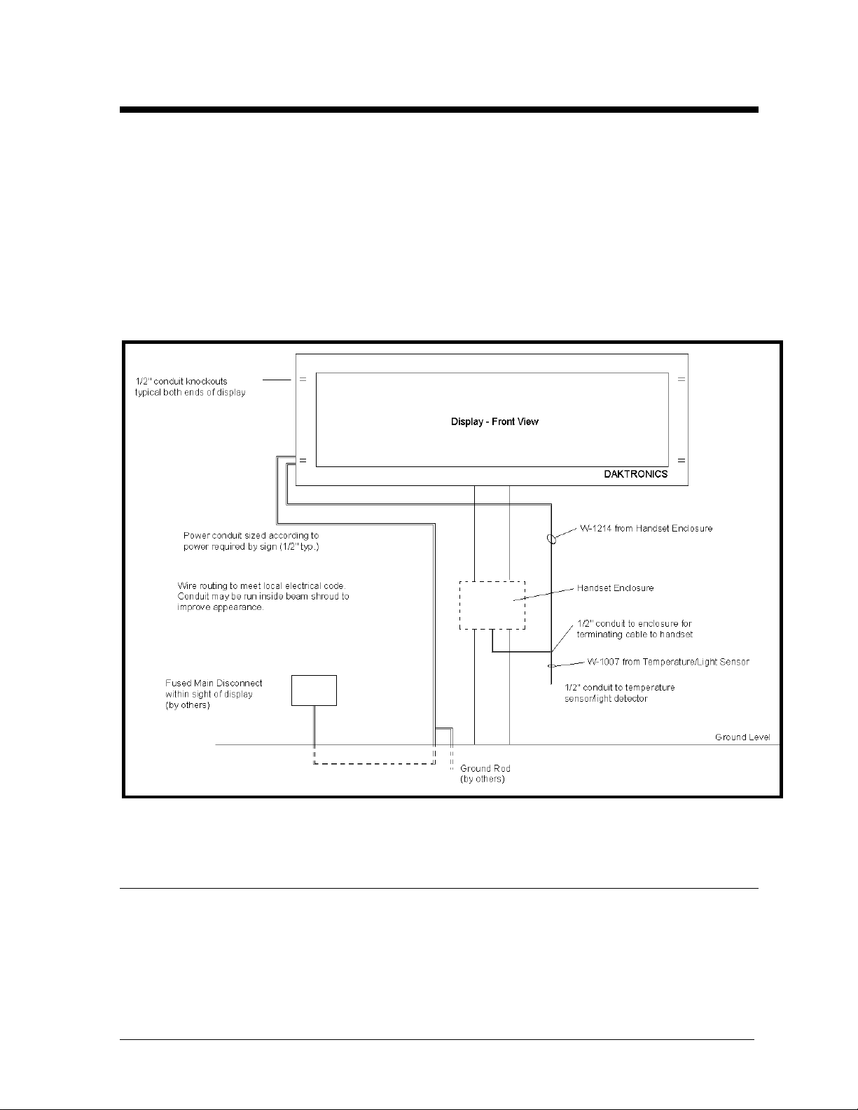
Knockouts for1/2” conduit are provided in the master display on either end of the display for signal and
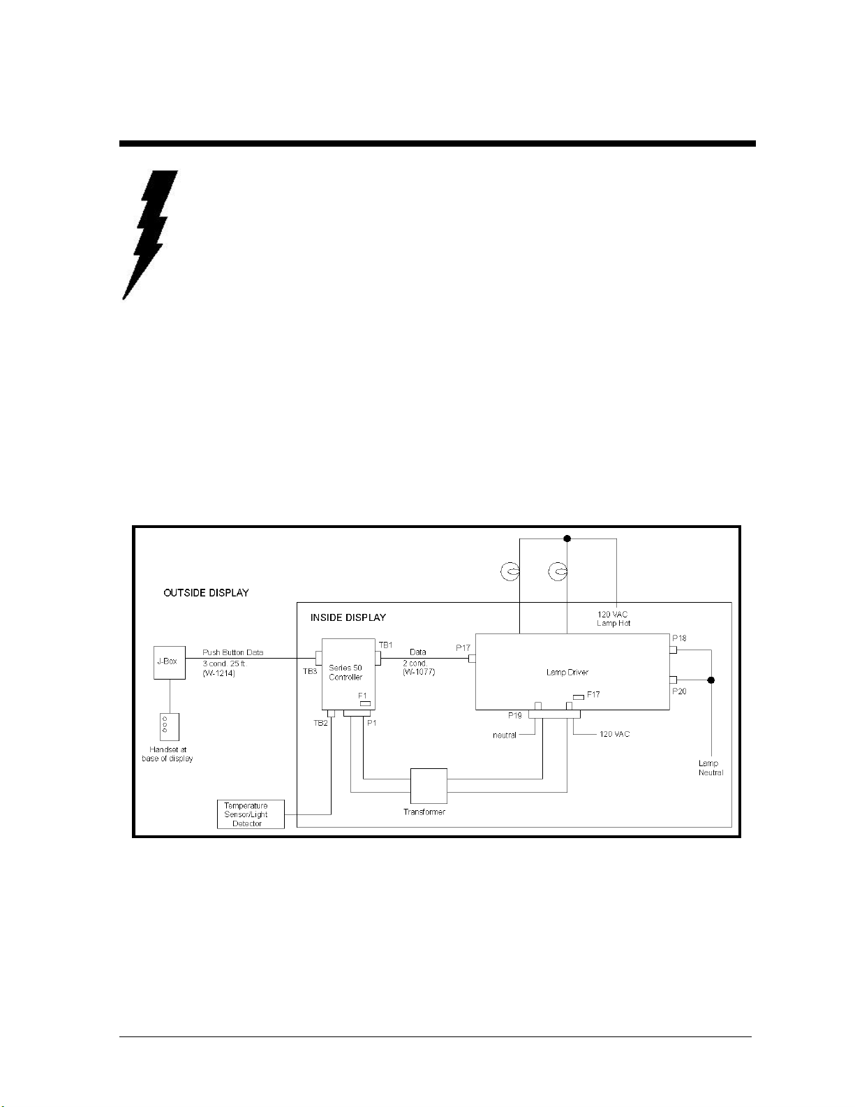
power entrance. Refer to the appropriate drawing in Section 1 for dimensions. Figure 1 shows the
general electrical layout of an installation.
Figure 1: Installation Electrical Layout
3.1 Display Access
Access the inside of the display through the hinged lampbank to perform electrical installation.
The lampbank is held closed with 1/4-turn fasteners along the bottom. Release the fasteners
and swing the lampbank open. Cut the cable ties on the prop rod and secure the lampbank
open.
(25 ft. typical)
Electrical
Installation
3-1
Page 24

On a large display (36”, 48”, and 60”), the lampbank is in multiple doors. The internal
components are located under the far left door when viewed from the front.
Drawing A-57279 is an illustration of the termination panel. Drawing A-87841 shows the
controller and component access. The power connections are made on the power termination
panel located in the master unit. The signal connections are made directly to the display
controller. The controller is located in the master unit in an enclosure. The enclosure cover
must be removed.
3.2 Power Connection
Note : When power is run to the display, a disconnect switch or plug must be provided within
sight of the display. To maintain CSA listed display, use the supplied disconnect.
Refer to Drawing A-57279 and A-57319. Power is supplied to the display through the
terminal block labeled TB41. The service required for a single face display is 120 VAC.
Service for a 2V display is 120/240 VAC single phase. The display amperage is stated on the
display specification label. Follow the instructions below to connect power to the display.
1. Run power through conduit into the display through one of the knockouts provided and
route over to the termination panel.
2. Connect the white neutral wire(s) to position 2 “NEUT” on TB41.
3. Connect a 120 VAC line to position 1 “01 (120 VAC)” on TB41.
4. For a 2V display, connect the second hot line of the 120/240 VAC service to position 3,
“02 (120 VAC)” on TB41. (Do not use two lines of a 120/208 three phase Wye service).
Exceptions: For 48” and 60” models, power is run separately to each face. Both positions 1
and 3 of TB41 are needed for one face and must be connected to a 120/240 VAC single phase
service. Check the specification label on the display for amperage. Refer to Drawing A-
67341.
For a 12” 2V model, use a single 120VAC line and connect a jumper from position 1 to
position 3 on TB41.
3.3 Grounding
All power service must be supplied with an earth-ground wire. Use the following instructions
to properly ground the display:
1. Attach the ground wire to the earth ground lug in the termination panel marked with “Earth
Ground” (Drawing A-57279).
2. Attach the ground wire to a copper earth ground rod installed according to the National
Electrical Code. Do not ground to any steel columns supporting the display.
3-2
Electrical
Installation
Page 25

3.4 Handset Connection
Note: For indoor controller operation, refer to Appendix A.
The handset enclosure consists of a small weatherproof box which houses the handset and a
junction box (refer to Figure 2). A 25-foot signal cable is provided to connect the handset
enclosure to the display. The end terminated with spade lugs goes to the handset j-box. Install
the handset as follows: Note: This signal cable has a typical 25 foot length and a maximum
50 foot length. Cable length beyond this is not recommended.
1. Mount the handset enclosure at the base of the display in a position where it will be
possible to see the display when using the handset. The handset has a six -foot cable that
plugs into the j-box.
2. Run the signal cable (Belden 8771, Daktronics part number W-1214) through1/2” conduit
from the handset enclosure into the display, and route to the display controller enclosure.
Knockouts are provided in both the handset enclosure and the display.
3. Remove the cover from the handset j-box and route the cable into the j-box. Connect the
three wires terminated with spade lugs to the terminal block mounted on the j-box cover.
Connect CLR (SIG) to WHT, BLK, and RED respectively, already connected to the
terminal block. Cut the shield back and leave it unterminated. Replace the cover and plug
in the handset.
4. Remove the cover from the controller enclosure and connect the control cable to TB3 on
the controller. Connect CLR to position 1, RED to position 6, and BLK to position 5.
Connect the shield drain wire to position 5 as well.
Figure 2: Handset and Enclosure
3.5 Temperature Sensor/Light Detector
Electrical
Installation
3-3
Page 26

The temperature sensor/light detector (optional) is mounted separately and requires a location
away from the influence of chimneys, air conditioners, or vents which can cause abnormal
temperature fluctuations. Usually a separation of at least 20-30 feet horizontally is required to
achieve this. Locations where air movement is restricted are also unsatisfactory.
A first choice sensor location is a north eave or northern exposure. This location gives extra
stability and accuracy to the sensor because of added shading usually obtained on a northern
exposure.
The second choice for locating a temperature sensor is on the display itself, or somewhere on
the display structure. A light-colored display is preferred in this application. Location of the
sensor should be on a northern edge of the display to try to keep the sensor shaded. Greater
accuracy is obtained if there is grass below the sign rather than concrete or some other
material. Display mounted sensors are generally discouraged because of the potential of the
display to self -heat from the sun, causing erroneous temperature readings.
3.5.1 Eave Mounting of Sensor
Drawing A-15267 shows a temperature sensor that has been mounted under a roof
eave. After connections are made, inspect connections, fold wires away, and secure
with #10 screws.
3.5.2 Connection to Controller
A 5-conductor 18-gauge cable (Belden 8465, Daktronics part number W-1007) is used
to connect the temperature/daylight sensor to the display controller. Maximum length
is 1,000 feet. Install as follows:
1. Connect the cable to the temp sensor as shown in Drawing A-15267 and route
through ½” conduit to the display. To reduce the conduit entrances, route this
cable into the display through the same conduit used by the handset controller
signal cable (refer to Figure 4).
2. Route the cable to the display controller enclosure and connect the cable to TB2
on the controller (refer to Drawing A-57319). TB2 is marked with the proper
wire colors (1-white, 2-black, 3-red, 4-brown, 5-green, 6-N.C.).
3.6 Master/Slave Connection
3.6.1 12”, 18”, 24” and 36” Displays
The slave display is electrically connected to the master display by means of an
interconnect harness provided in the slave display. This harness should be routed from
the slave display into the master display using a conduit nipple or other appropriate
method. When back-to-back, the displays can have a maximum separation of 24” due
to the harness length.
3-4
Electrical
Installation
Page 27

The interconnect harness consists of eight (8) digit cables, four(4) power wires, and a
ground wire. Each digit cable has a nine (9) position plug on it. The plugs are labeled
2, 4, 6 … 16.
1. Connect these cables to the jacks along the bottom of the driver inside the master
display, starting with plug 2 on the left end proceeding to plug 16 on the right.
2. Connect the four (4) black power wires to fuses F46-F49 on the power
termination panel. Make sure incoming power is connected to position 3 on TB41,
“02 (120 VAC).”
3. Connect the green ground wire into the earth ground lug, E41, on the power
termination panel. The installer is responsible for protecting the interconnect
harness between the two displays.
3.6.2 48” and 60” Displays
48” and 60” displays do not have the master/slave interconnect harness. The slave
display connects to the master display by a two (2) conductor control cable (Belden
8451, Daktronics part number W-1077). This cable is provided in the slave face.
Route the cable through the conduit to the master display. Connect the cable as
shown:
Cable TB1
RED Pin 3
BLK Pin 4
The installer is responsible for providing conduit to protect the control cable between
the two displays.
Electrical
Installation
3-5
Page 28

Page 29

Page 30

Page 31

Page 32

Page 33

Page 34

Page 35

SECTION 4 : Operation
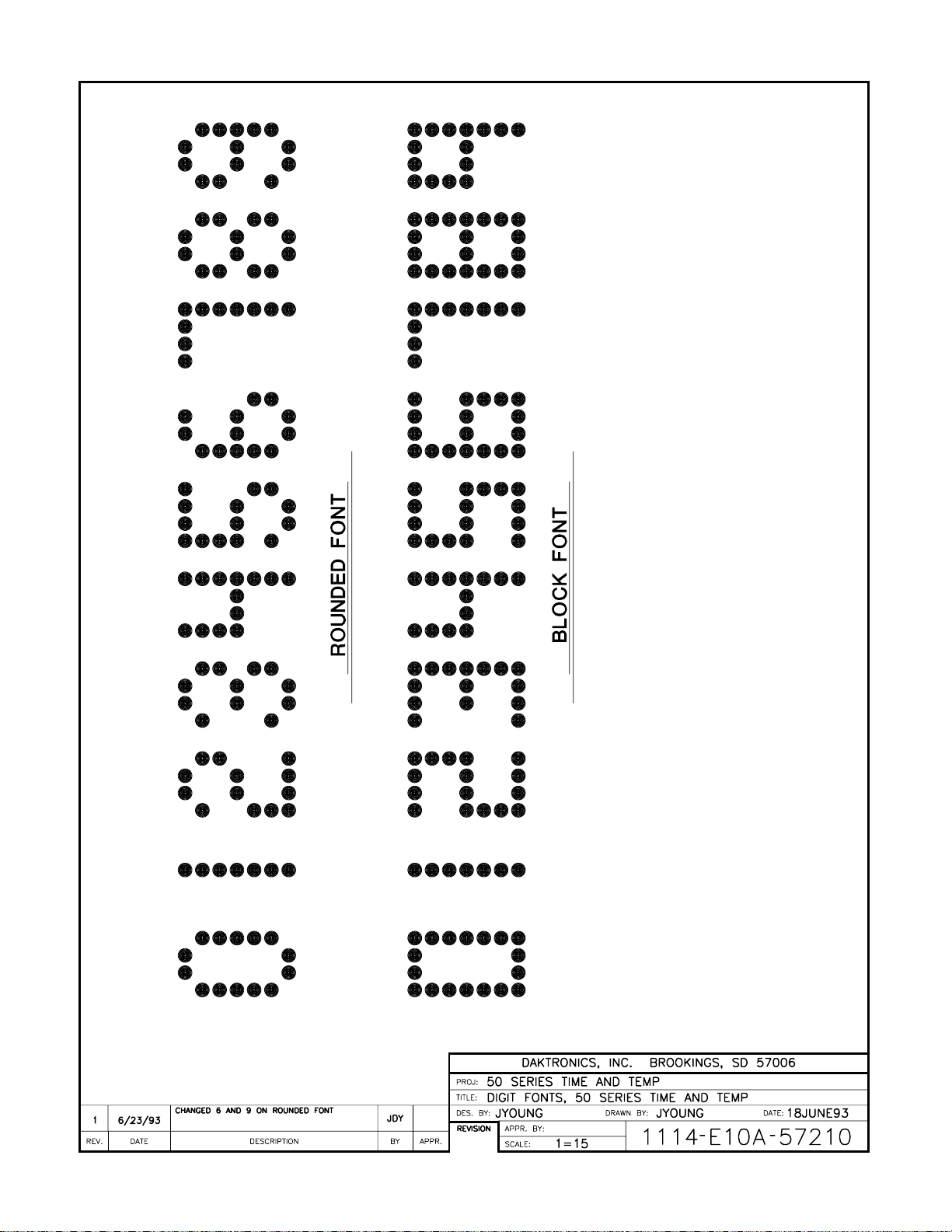
Reference Drawings: Font Selections .................................................Drawing A-57210
Component Acce ss & Controller......................Drawing A-87841
This section outlines the operation of a Series 50 time and temperature display. This display uses a
standard 16 column lampbank driver and a Series 50 controller built into the cabinet of the display. The
controller is programmed using a handset which is stored at the base of the display. The handset has
three push button switches which are used to set the time, price, and display function values of the
controller (refer to Figure 2). This information is stored internally in memory on the controller, which
has a battery backup. The battery has a rated life of about 10 years.
This display is capable of showing the time (in either 12 or 24 hour format), temperature (in both
Fahrenheit and Celsius), and two price values (free format). This information can be shown in various
combinations selected by the operator.
4.1 Using the Handset to Program the Controller
When power is turned on to the display, it will go through a power-up test. First, the lampbank
driver will do its power-up test of every other row, the controller will show the revision number
and then will go into Operating mode (showing the programmed sequence of time and/or
temperature and/or price).
The first button on the handset is labeled SET. The [SET] button steps the display controller
through its different modes. Pressing [SET] once will put the controller in the Function Set
mode. This mode is used to set all function values for the display. Pressing the button a
second and third time puts the controller in the Price Set modes for Price #1 and Price #2
respectively. Pressing the [SET] button a fourth time returns the controller to Operating mode.
The second button on the handset has multiple functions. In Operating mode, it will set the
HOURS value; in the Function Set mode, it is used to advance through the FUNCTION
numbers; in the Price Set modes, it is used to advance through the digit positions.
The third button on the handset also has multiple functions. In Operation mode, it will set the
MINUTES value; in the Function Set mode, it is used to step through the function VALUES;
in the Price Set modes, it is used to step through all the possible characters for a digit position.
4.2 Setting the Time
The time on the display is set while it is in the operating mode. In order to set the hours, press
the second button until the proper HOURS value is displayed. In the 12-hour format, an A or
a P will be displayed in the far right digit to represent AM or PM values. To set the minutes,
press the third button until the proper MINUTES value is displayed. After setting the time,
the display will return to the operating mode in a few seconds.
Operation
4-1
Page 36

4.3 Setting the Functions
The FUNCTION SET mode is used to adjust the 14 FUNCTION values of the display.
These functions include such things as hold time and display sequence.
To enter this mode, first push the first button, labeled SET. When this button is pressed, the
display will show an “F1.” Pressing the second button [FUNCTION] will advance through the
14 function numbers.
To see what the current value of a function is, advance to that function number and then press
the third button [VALUE]. When this button is pressed, the current value of the function will be
displayed. To change this value, press and release the [VALUE] button until the proper value is
displayed. Advance to the next function to save this value by pressing the [FUNCTION] button.
This will cause the next function number to be displayed. By alternately pushing the
[FUNCTION] button to advance the functions and the [VALUE] button to show the value, all of
the current function values can be viewed.
The display can be returned to the operating mode at any time. If a function number is being
displayed, press the [SET] button once to return to the operating mode. If one of the function
values is being displayed, press the [SET] button twice to return to the operating mode. The
display will blank for a few seconds before returning to the operating mode. If function
number “F1” is being displayed, pressing the [SET] button will advance the display to the Price
Set Mode (refer to Sections 4.1 and 4.6).
4.4 The 14 Display Functions
Function 1: Display Frame Duration
The display frame duration function controls the time that each value in a sequence is
displayed (hold time). The time value is adjustable from 2 to 9 seconds. The best value to
use here will depend on such factors as traffic speed and the display sequence. (Default:
3)
Function 2: Display Sequence
The display seque nce is the order in which time, temperature, or price values are to be
displayed. Available sequences are given in the following table:
4-2
Operation
Page 37

Sequence # Display Sequence
0 Temp in F - Temp in C
1 Time -Temp F
2 Time - Temp C
3 Time - Temp F - Temp C
4 Time - Temp F - Time - Temp
C
5 Time
6 Temp F
7 Temp C
8 Price #1
9 Price 1 - Time
10 Price 1 - Temp F
11 Price 1 - Temp C
12 Price 1 - Time - Temp F
13 Price 1 - Time - Temp F - Temp
C
14 Price 1 - Time - Temp F - Temp
C
15 Price 1 - Price 2
16 Price 1 - Price 2 - Time
17 Price 1 - Price 2 - Time - Temp
F
18 Price 1 - Price 2 - Time - Temp
C
19 Price 1 - Price 2 - Time - Temp
F - Temp C
20 Lamp Test
Each value in a display sequence will be displayed for a period of time determined by the
value set for the Display Frame Duration function. When the last item in a particular
sequence is finished, the sequence will repeat (Default: 1). (Display sequences 8-20 not
available in 7/8 segment mode.)
Function 3: Dimming
For night viewing, the display uses the dimming mode of the lamp driver. This function
determines how dimming is controlled. A value of “0” sets this function to Automatic
operation, where dimming is controlled by a photocell on the temperature sensor/light
detector. The controller will set the lamp driver to full Bright during the day and to Dim
mode at night. The controller can also be set to stay in Bright or Dim mode. Set this
function value to “1” for Manual Bright. Set the value to “2” for Manual Dim. (Default:
0.)
Function 4: Font Select
One of two fonts can be selected using this function. The two fonts, rounded and block,
are illustrated in Drawing A-57210. A value of “0” will select the block font. A value of
“1” will select the rounded font. (Default: 0)
Operation
4-3
Page 38

Function 5: Temperature Offset
Sometimes the reading from a temperature sensor may be consistently low or high. This
may occur due to the location of the sensor or the actual difference in temperature
between the sensor location and a reference being compared to (e.g. a radio station). This
can be corrected by programming a plus or minus temperature offset. Function 5 can be
set with values from -9 to +9 degrees Fahrenheit. This value will be added to or
subtracted from the reading from the sensor. (Default: 0)
The temperature offset is entered in Fahrenheit. To obtain a given offset in Celsius, the
value must be converted as follows:
Offset Degrees F
(Offset Entry)
(+ or -)
0 degrees 0.0 degrees
1 degree 0.6 degrees
2 degrees 1.1 degrees
3 degrees 1.7 degrees
4 degrees 2.2 degrees
5 degrees 2.8 degrees
6 degrees 3.3 degrees
7 degrees 3.9 degrees
8 degrees 4.4 degrees
9 degrees 5.0 degrees
Note : OFFSET (degrees C) = OFFSET (degrees F) x 5/9
Function 6: Temperature Indicator
This function determines the indicator displayed with a temperature value. Indicators used
are: degree symbol, “c,” “C,” “F” or blank. (Default: 1). These are the indicator
combinations available:
Value
0
1
2
3
Functions 7-10: Shut Down Feature
The controller can be programmed to go into a shut down mode that blanks the display at a
programmed time, and starts the display back up at a later time. This allows the display to
be blanked during low traffic hours each day. Function 7 is “Start Up Hours.” This
value is displayed in 24-hour format. Function 8 is “Start Up Minutes.” Function 9 is
“Shut Down Hours” in a 24-hour format. If a value of 99 is programmed, no shut down
will occur. Function 10 is “Shut Down Minutes.” (Defaults: 0, 00, 99, 00)
Temperature
Displayed
Fahrenheit
Fahrenheit
Fahrenheit
Fahrenheit
Offset
Degrees C
Celsius
Celsius
Celsius
Celsius
Indicator
Displayed
blank
“c”
degree
“C”
“F”
“C”
“F”
degree
4-4
Operation
Page 39

Function 11: Day of Week
This function sets the current day of the week. Values of 1 through 7 are used to
represent Sunday through Saturday respectively. (Default: 1)
Function 12: Date
This function sets the current date. Values of 1 through 31 can be programmed. The
controller automatically adjusts for months with fewer than 31 days (inc luding leap year).
It is the user’s responsibility to make sure the correct date is programmed initially. If an
incorrect value is programmed, the calendar will be miscalculated. (Default: 1)
Function 13: Month
This function sets the current month. Values of 1 through 12 are used for the months of
January through December respectively. (Default: 1)
Function 14: Year
This function sets the current year. Values of 90 through 99, and 00 through 20 are used
for the years 1990 through 2020. (Default: 93)
Operation
4-5
Page 40

4.5 Operation Summary
Function # Description Range
1 Display Frame Duration 2-9 Seconds
2 Display Sequences
T = Time
F = Fahrenheit
C = Celsius
P1 = Price #1
P2 = Price #2
Note: Sequences 8 - 20 are not available in 8/7 segment
mode.
0 = F, C 11 = P1, C
1 = T, F 12 = P1, T, F
2 = T, C 13 = P1, T, C
3 = T, F, C 14 = P1, T, F, C
4 = T, F, T, C 15 = P1, P2
5 = T 16 = P1, P2, T
6 = F 17 = P1, P2, T, F
7 = C 18 = P1, P2, T, C
8 = P1 19 = P1, P2, T, F, C
9 = P1, T 20 = Lampbank Test
10 = P1, F
3 Dimming 0: Automatic
4 Font Select 0: Block
5 Temperature Offset -9 to +9 degrees F
6 Temperature Indicator 0-3
7 Start Up Time - Hours 0-23
8 Start Up Time - Minutes 0-59
9 Shut Down Time - Hours 0-23, 99 (disable)
10 Shut Down Time - Minutes 0-59
11 Day of Week 1-7
12 Date 1-31
13 Month 1-12
14 Year 90-99, 00-20
Value
0
1
2
3
Temp.
Displayed
F
C
F
C
F
C
F
C
Indicator
Displayed
blank
“c”
degree
“c”
“F”
“C”
“F”
degree
Selections 0-20
1: Bright
1: Rounded
2: Dim
4-6
Operation
Page 41

4.6 Setting the Price Values
This display is capable of showing not only time and temperature but also two separate price
values. Refer to “Function 2: Display Sequences” for different possible combinations.
The price values are free format, which means that for either price, each of the four digits and
the decimal point is set to exactly the character that is desired for that digit position. The
characters for each position include digits 0 - 9, a “blank,” and possibly some special
characters.
To set Price Value #1, press the [SET] button so that an “F1” is being shown. Now press the
[SET] button again. Price Value #1 is now being shown. A flashing cursor will indicate what
digit position is selected. The cursor is the bottom middle two lamps for each digit. The colon
will flash to indicate when the decimal position is selected (the colon is not part of the price
value; it simply indicates that the decimal position is selected). The cursor will start off in digit
position #1 (on the left). Set this digit to the value desired using the [VALUE] button. When
done, advance to the next digit using the [FUNCTION] button. The positions will advance:
digit#1, digit#2, digit#3, digit#4, decimal point, and then wrap around to digit#1 again. Step
through each digit position with the [FUNCTION] button and set the digit to the desired value
with the [VALUE] button.
When done setting Price Value #1, advance to Price Value #2 by pressing the [SET] button
again. Set each digit of Price #2 to the desired values in the same manner. For either price,
you do not need to advance through the digits if you do not want to change any of the values.
If you are not using Price #2, do not change it.
When done setting Price Value #2, return to operating mode by pressing the [SET] button
again. The display will blank for a few seconds before resuming operation.
The Price Set Modes can only be entered into by pressing the [SET] button when Function
Number 1 (“F1”) is being shown on the display. If the [SET] button is pressed when any
other function number is being shown, the controller will return to operating mode.
Price Digit
Position
Characters
Available
#1 0 - 9
blank
+
1 .
.
#2 0 - 9
blank
#3 0 - 9
blank
#4 0 - 9
blank
small 9
decimal ON, OFF
Operation
4-7
Page 42

4.7 Operation without Temperature Sensor/Light Detector
Although the time and temperature display was designed to be operated with a temperature
sensor/light detector, there may be situations when it will be required to operate without one.
(Such as when the sensor has failed and the replacement has not yet arrived, or in systems
where the temperature will not be used.)
If the sensor is disconnected, the display driver will sense this and will not display any
temperatures. When the sensor is reconnected, the display will again show any temperature
values as selected by the Display Sequence . Therefore it is not necessary to change any
settings on the display if the sensor is being disconnected for a short period of time (such as for
replacement). If it is desired to permanently operate without a temperature sensor/light
detector or if the sensor is used for the photocell only, set Function 2 (Display Sequence) to a
value that does not include temperature. Without a sensor, Dimming (Function 3) must be set
to Manual Bright or Manual Dim.
4.8 Switch Settings
The display controller has a set of eight switches in a package (DIP Switch) that also set some
of the operations of the controller. Refer to Drawing A-87841 in Section 3 for an illustration
of the location of these switches on the controller. The first switch, SW1, will put the
controller into a Lampbank Test mode when it is turned ON. When the test is started, the
display will show the software revision number in the right-hand digit for three seconds. The
test will then alternately turn the display lamps ALL ON for five seconds, then ALL OFF for
one second until SW1 is turned OFF again. If SW2 is turned ON while SW1 is ON, the
display lamps will cycle through a pattern of digits.
The display controller can get its time base from one of two sources: a 50 or 60 hertz power
line frequency, or its internal real time clock (RTC). When the controller is first turned on, it
will sample the power line frequency to ensure that there is an accurate 50 or 60 hertz
frequency. If the frequency is not accurate, the controller will use the internal real time clock.
The controller can also be forced to run off the real time clock with switch SW3. Turn SW3
ON to force the display driver to run off of the internal real time clock. This switch is only
checked on power-up. It is preferred to use the power line frequency.
The Series 50 display can be run in either a 12-hour or 24-hour time format. Turn switch SW4
OFF to run in 12-hour format. Turn SW4 ON to run in 24-hour format. This switch is only
checked on power-up.
The controller will automatically adjust the time for daylight savings changes if SW5 is OFF.
The time will be advanced by one hour at 2 a.m. on the first Sunday in April. The time will be
set back one hour at 2 a.m. on the last Sunday in October. This function will be disabled if
SW5 is turned ON.
If the indoor control option is used, SW6 must be ON. If an eight-column driver (12” model) is
used instead of a 16-column driver, SW7 must be turned ON.
If the display being controlled uses standard 7 or 8 segment digits, SW8 must be turned ON.
This mode will only allow use of display sequences 0-7 of Function 2 (Section 4.4).
4-8
Operation
Page 43

Switch Summary
Switch # Function
1 Test
2 Alternate
3 RTC
4 12/24 Hour
5 Daylight Savings
6 Indoor Controller
7 8-Column Driver
8 7/8 Segment Mode
Operation
4-9
Page 44

Page 45
Page 46

Page 47
SECTION 5 : Maintenance & Troubleshooting
Reference Drawings: Lamp Driver, 16 col. w/ Fan..............................Drawing A-37070
Digit Wiring Diagram, 48” & 60” T&T................Drawing A-67339
Component Access & Controller......................Drawing A-87841
This section outlines maintenance and troubleshooting for Series 50 Time and Temperature displays.
The layout and operation of the display components are explained first. Troubleshooting steps are
outlined as well. Figure 3 shows the component layout for a display. Drawing A-87841 (in Section
3) shows the location of these components in a display. All of these components are located in the
master face.
IMPORTANT NOTES:
1. Display power must be turned off before any repair or maintenance work
is done on the display.
2. Any access to internal display electronics must be made by qualified
service personnel.
3. If the Data Time Series 50 controller is being used as an update from the
DATA TIME I, please refer to Appendix C.
Figure 3: Block Diagram/Component Layout
Maintenance &
Troubleshooting
5-1
Page 48

5.1 The Lamp Driver
The component that switches the lamps ON and OFF in this display is called a lamp driver or
driver. The driver receives data on a pair of wires from the controller. The driver uses this
data to determine which lamps are switched ON. The lamp driver switches the lamps with a
triac. There are 128 triacs, 16 columns with 8 rows each. The rows are also referred to as
segments and are labeled “a” to “h.” Drawing A-37070 shows a layout of the driver.
The hot side of 120 VAC power is wired directly to the digit lamps from fuses in the power
termination panel. The driver switches neutral to the lamps through the triacs. This neutral is
brought into the driver on pins 1 and 2 of J18 and J20.
The lamp driver has 16 jacks (one per column) for switching digit lamps. Figure 4 shows the
pin assignments and color code for the plugs that mate to these jacks. The jacks are divided
into two groups as follows:
Master Digits: J1, J3, J5, J7, J9, J11, J13, J15
Slave Digits: J2, J4, J6, J8, J10, J12, J14, J16
Plugs from all the digits are connected directly into these jacks on the lamp driver. Figure 4
shows the order that these plugs are connected to the lamps in the digits.
The lamp driver LED indicators are located near J17 (refer to Drawing A-37070). Their
functions are as follows:
PWR: Lamp Driver Logic Power (-5 volts)
ON: Power is present.
RST: Monitor Reset
ON: Monitor is resetting La mp Driver Electronics.
OFF: Normal operation. Monitor checks -5V power, processor execution.
DATA: Data Signal Input
ON: Signal from controller is present (will blink with data).
OFF: No signal present.
TEST: Lamp Driver Status
This LED flashes at different rates to indicate the status of the lamp driver.
Flash Rate Status
Twice per second Running test pattern
Once per second Connected to controller data (normal operation)
Once per two seconds Not connected to controller data
5-2
Maintenance &
Troubleshooting
Page 49

Figure 4: Dot Matrix Digit Segmentation for 18", 24", 36"
5.2 The Display Controller
The Series 50 display controller is located inside the display cabinet next to the lamp driver. It
controls all operations of the display. It keeps track of the time and stores programmed values.
The controller processes internal information and information from inputs and sends display
data out to the lamp driver.
Maintenance &
Troubleshooting
5-3
Page 50

5.2.1 Connectors
The controller receives input from the temperature sensor (TB2) and handset (TB3)
and sends out data to the lamp driver (TB1). Power is brought into the controller on
J1. Refer to Drawing A-37070 for locations of these connectors on the controller.
The following tables show the pin functions of the jack and terminal blocks.
J1 TB1
Pin Function Pin Function
1 Power (10 VAC) 1 Data Out 1+
2 Power (10 VAC) 2 Data Out 13 Reset 3 Data Out 2+
4 Reset Ground 4 Data Out 2 5 Switch 1+
6 Switch 1 7 Switch 2+
8 Switch 2-
TB2 TB3
Pin Function Pin Function
1 Photocell 1 RX (Handset)
2 GND 2 TX
3 +5 Volts 3 CTS
4 GND 4 RTS
5 Temp. In 5 GND
6 GND 6 +5 Volts
7 Network +
8 Network 9 C.L. +
10 C.L. -
5.2.2 Switches
Refer to Drawing A-37070 for the location of the DIP switch package on the
controller. The following table shows the function of each switch. Refer to Section
4.8 for additional switch setting information.
Switch # Function
1 Lamp Test
2 Alternate Test
3 Real Time Clock
4 12/24 Hour
5 Daylight Savings
6 Indoor Controller
7 8 Column Driver
8 7/8 Segment Mode
5-4
Maintenance &
Troubleshooting
Page 51

5.2.3 Status Indicators
The LED indicators show the status of the display controller. These indicators can be
used to determine controller problems. Refer to Drawing A-37070 for the location of
these LEDs. Their function is as follows:
PW2: Temperature Sensor/Light Detector Power (+5 volts).
ON: Power is present.
PHO: Temperature Sensor/Light Detector Status.
ON: Sensor is detecting a BRIGHT condition.
OFF: Sensor is detecting a DIM condition (or sensor is
disconnected).
TMP: Temperature Sensor Status.
ON: Temperature sensor input detected.
OFF: No sensor input.
PW1: Display Controller Main Logic Power (+5 volts).
ON: Power is present.
DS5: Not used (OFF).
DS6: Not used (OFF).
DS7: Source of Clock Time Base.
ON: Internal Real Time Clock.
OFF: Power Line Frequency (50 or 60 Hertz).
DS8: System Clock.
Turns ON and OFF at one second intervals.
RST: Monitor Reset.
ON: Monitor is resetting Controller Microprocessor.
SIG: Signal Input (from handset).
ON: Signal from handset is present (will blink with data).
OFF: No signal present.
5.3 Troubleshooting
When a problem occurs with the display, the first step is to isolate the display component that
is causing the problem. Some troubleshooting can be done without opening the display. Any
troubleshooting requiring access inside the display should be done by a qualified service person.
OFF: Normal operation. Monitor checks +5V power, processor
execution.
Maintenance &
Troubleshooting
5-5
Page 52

If opening the display, first make sure the display power is turned OFF. Release the 1/4-turn
fasteners at the bottom of the display, hinge the face panel up, and swing the prop rod out and
place it in the holding bracket. Once the display is open, power can be turned ON again for
troubleshooting purposes.
Caution should be taken when troubleshooting with display power ON, and only
qualified personnel should attempt this.
5.3.1 Power-Up Tests
The power-up test is a simple test that checks the operation of most display
components. Turn the display power OFF for at least five seconds by throwing the
breaker(s) to the display. Turn power to the display back ON and observe the digits.
The lamp driver will first do a power-up test. This test is independent of the controller.
The lamp driver will (1) turn every other segment in all column outputs ON for two
seconds and then (2) turn the alternate segments ON for another two seconds and
then (3) blank.
The controller waits six seconds after power is turned ON to do its pow er-up test.
While it is waiting, the controller will turn ON DS5-DS8 and then turn them OFF one
at a time, at one second intervals. After the six second delay, the controller will send
data to the driver to show the software revision number. This is shown on the righthand digit of the display for three seconds and then the controller goes into normal
operating mode.
If the display fails one of these tests, careful observation should indicate which
component is not working properly. It may be necessary to gain access to the
termination panel, driver, and/or controller. Check the fuses and connections to see
that power is being supplied properly. Check the LEDs, especially the power LEDs,
on both the driver and controller.
5.3.2 Controller Lamp Test
The controller can be set to run a lamp test in two different ways:
1. It can be run from the handset by setting the Sequence Number (Function #2) to a
value of 20. Once the test is running, press any of the buttons on the handset to
exit the lamp test.
2. The test can also be run by turning on SW1 on the controller as described in
Section 4.8.
When the lamp test is started, it will show the controller software revision number in
the right hand digit for three seconds. The test will then alternately turn the display
lamps ALL ON for five seconds and then ALL OFF for one second until the test is
stopped.
This test is very useful for performing routine maintenance to check for burned out
lamps or failed triacs. If a lamp is not working, first check to see if it is burned out. If
not, the lamp socket, or connection to it, may have failed. Move the wire around close
5-6
Maintenance &
Troubleshooting
Page 53

5.3.3 Lamp Driver Test
5.3.4 Time and Temperature
5.3.5 Dimming
5.4 Repair
Repairing the display will usually require one of the following:
to where it connects to the socket to check for a faulty connection between the wire
and the socket.
If a lamp is stuck ON, it is probably a failed (shorted) triac. This can be fixed by
replacing the lamp driver (Section 5.4.3) or replacing the triac only (Section 5.4.4).
If a whole digit will not turn ON, check the fuse for that digit (Section 5.4.1). In
some cases when a lamp burns out, it will cause a triac to short.
The lamp driver can be set to run a lamp test. This test can be used to check the lamp
driver outputs independently from the controller signal input. The test will alternate
between the two patterns of every other segment turned ON in each column output.
Locate two pads labeled “TEST” next to J19 on the driver. With the tip of a
screwdriver blade, momentarily short these two pads together just long enough to
make the test pattern appear. To exit the test mode, momentarily short these pads
together again just long enough to stop the test pattern.
If the display does not keep time accurately and/or the temperature is not stable, try
running the controller off the Real Time Clock (refer to Section 4.8). If the controller
is running off the Real Time Clock, try the Line Frequency. This will help determine if
one of these time bases is faulty. Accurate timing is necessary for both time and
temperature to operate properly. If the power line frequency is bad, either consult the
power company or an electrician to get it corrected or run off the Real Time Clock.
The Line Frequency is preferred, but the Real Time Clock is very accurate. If the
Real Time Clock is not working properly, the controller should be replaced or repaired.
A problem with the temperature may also be caused by a faulty temperature sensor or
connection. Check the LED indicator labeled “TMP” on the controller to see that it is
ON. It may be necessary to try another sensor. Remember: if the temperature sensor
input is out of the normal operating range (not connected), the display will not show the
temperature at all.
Dimming can be most easily checked during the day by covering the temperature
sensor/light detector for a minimum of five seconds. If this does not work, set the
controller to Manual Dim and Manual Bright using Function #3. If this does not work,
try replacing the driver. If Manual settings work but Automatic settings do not, check
the LED labeled “PHO” on the controller (refer to Section 5.2.3). It should turn OFF
when the sensor is covered. Replace the sensor if necessary.
• Replacing a lamp (routine maintenance)
• Replacing a blown fuse
Maintenance &
Troubleshooting
5-7
Page 54

• Exchanging a faulty controller or driver
• Replacing a shorted triac
Important notes for service done inside the display:
• This service should only be done by qualified service personnel.
• Use caution when turning power on to the display while it is open.
• Make sure all connectors are plugged back in, all fuses are in place, all fasteners
are secured, all tools are removed, and all wires are held out of the way before the
display is closed up.
5.4.1 Fuse Replacement
Be sure to check the fuses on the driver and controller and not just on the termination
panel. Note : Replace fuses with type and rating specified.
Fuse # Location Protects Fuse Type & Rating
F1 Controller Controller AGC-1 Amp
F17 Driver Driver Logic AGC ½ Amp
F41 Term Panel Electronics AGC ½ Amp
F42 Term Panel Master Digit 1 MDL -7 Amp
F43 Term Panel Master Digit 2 MDL -7 Amp
F44 Term Panel Master Digit 3 MDL -7 Amp
F45 Term Panel Master Digit 4 MDL -7 Amp
F46 Term Panel Slave Digit 1 MDL -7 Amp
F47 Term Panel Slave Digit 2 MDL -7 Amp
F48 Term Panel Slave Digit 3 MDL -7 Amp
F49 Term Panel Slave Digit 4 MDL -7 Amp
5.4.2 Exchanging a Controller
If the controller is suspected to be malfunctioning, exchange it and test the display
again. Gain access to the display (with power OFF). Release the two 1/4-turn
fasteners on the controller enclosure cover and remove the cover. Disconnect the
power plug and the three terminal blocks. Note : Unplug terminal blocks – do not
remove the individual wires. Remove the four nuts holding the controller printed
circuit board in place and remove. Replace with the new controller, secure with the
nuts and plug in all the connectors. With caution, turn the power back ON with the
controller in view so that the LEDs can be checked. If the display is working properly,
close it up.
5.4.3 Exchanging a Lamp Driver
Open the display (with power OFF). Disconnect all the plugs to the lamp driver. Note
proper plug locations as you disconnect them. Remove the wing nuts that hold the
driver in place (not the wing nuts on the driver cover). Remove and replace the
driver. Test with the display open so that the LEDs can be checked. Close up the
display.
5-8
Maintenance &
Troubleshooting
Page 55

5.4.4 Replacing Triacs
If service personnel are skilled in soldering and desoldering techniques, it will be more
efficient to replace failed (shorted) triacs on site rather than exchanging the whole
lamp driver. The key to this is locating the failed triac. Figure 5 (located in
Appendix A) shows the triac assignments for the lamps in the digit. Figure 4 shows
the location and numbering of the triacs on the lamp driver. Identify the failed point on
the display using the lamp test. Locate the corresponding triac and replace it. The
cover and the tray on the lamp driver will need to be removed.
5.5 Structural Inspection
Visual inspection should be done periodically to check the paint appearance and to check for
corrosion, especially at footing bolts and support or guy cables. Fasteners should be checked
and tightened or replaced as required.
5.6 Replacement Parts List
Refer to the following list for replacement parts for Daktronics Series 50 Incandescent Time
and Temperature displays.
Parts Description Daktronics Part #
Lamp, 11S11 DS-1315
Lamp, 15A15 DS-1271 replaced with
Lamp, 15S14 DS-1248
Lamp, 30A15 DS-1076
Lamp, 30R20 DS-1126
Lamp, 33A19 DS-1075
Lamp, 50R30 DS-1281
Lamp Socket X-1142
Lamp Driver, 8 Column (12” Model) 0A-1033-0107*
Lamp Driver, 16 Column 0A-1033-0100*
Triac Q-1021*
Series 50 Controller 0P-1114-01*
Controller Transformer T-1072
Handset 0A-1085-0076
Temperature Sensor/Photocell 0P-1151-0001*
* = Suggested spare parts package
5.7 Unit Exchange/Replacement Procedure
Daktronics unique exchange program offers our clients the quickest, most economical way of
receiving product repairs. If a component fails, Daktronics will send the customer a
replacement. The customer, in turn, sends the failed component to Daktronics. This not only
saves money but decreases the time that the display is inoperable. Daktronics offers repair
and return on a timely basis; in urgent situations, every attempt is made to ship by the fastest
transit method available.
DS-1248
Maintenance &
Troubleshooting
5-9
Page 56

5-10
Maintenance &
Troubleshooting
Page 57

If, after the part is exchanged, the equipment still causes problems, please contact Daktronics
Customer Service immediately at 1-800-843-9879. If the replacement part fixes the problem,
package the defective part in the same packaging the replacement part arrived in, fill out and
attach the enclosed UPS shipping document, and return the part to Daktronics. Enclose your
name and address and list and describe all symptoms as clearly as possible.
1. Packaging for Return: Package and pad the item well to prevent damage during
shipment. Electronic components, such as printed circuit boards, should either be
installed in an enclosure or placed in an anti-static bag before boxing.
Please enclose your name and address and list all the symptoms. Please be as
specific as possible.
2. Driver Packaging Instructions: Drivers should be placed in a static-free enclosure
for return shipping. An anti-static convoluted foam packing is available from
Daktronics (part number PK-1135). The shipping box (Daktronics part number PK-
1006) should be used along with the foam.
3. Where to Send: Contact your local representative prior to shipment to acquire a
Return Material Authorization Number (RMA#). This will speed up the repair of your
unit.
When returning defective items under the exchange program, please use the UPS
Blue Return Tags found in the package containing the exchange unit sent from
Daktronics. This will speed up the transaction and help avoid confusion when the part
is returned to Daktronics. The defective item must be returned within 15 days
of receiving a replacement part. Using the UPS Blue Return Tag immediately will
eliminate the possibility of late charges being assessed against your account.
Mail: Daktronics, Inc., Customer Service
PO Box 5128
331 32nd Avenue
Brookings, SD 57006
Phone: Toll Free: 1-800-843-9879
or 1-605-697-4400
Maintenance &
Troubleshooting
5-11
Page 58

Page 59

Page 60

Page 61

Appendix A: Optional Indoor Controller
Console
Reference Drawings: Indoor Controller Schematic .............................Drawing A-59425
Series 50 Indoor Controller...............................Drawing A-87845
The body of this manual describes the installation and operation of a display with a handset at the base
of the display. If you purchased the optional indoor control console, there are only a few differences in
the installation and operation.
With the indoor control option, the controller circuit board is not mounted in the Master face of the
display. Instead it is located indoors in an enclosure that can be mounted to a wall or placed under a
desk or table. Signal cable runs from the controller enclosure to the master display face. The console
(with LCD – liquid crystal display) is plugged into the controller enclosure and is placed on top of a
desk, table, etc., for easy access. Refer to Figure 5 and Drawing A-87845.
Note: DIP Switch SW6 on the controller PCB must be ON for the indoor controller option.
This section describes the differences in signal connection and indoor console operation.
A.1 Controller Location
The control console (with LCD) must be placed indoors where the temperature is between 50
and 90 degrees Fahrenheit and the humidity is less than 90% (non-condensing). The console is
connected to the controller enclosure with a 25-foot cable. The controller enclosure is
powered by a 120 VAC input/12 VAC output wall transformer and must be within six feet of a
standard 120 VAC, 60 Hz outlet. Also, note that signal to the display and from a temperature
sensor must be routed to the controller enclosure.
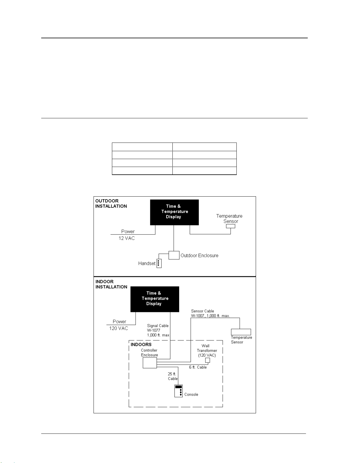
A.2 Installation/Signal Connection
The display is installed as stated in Sections 2 and 3 of this manual except for Sections 3.4
and 3.5.
A handset (Section 3.4) is not used with the indoor controller. Instead, the controller
enclosure and console need to be installed. Install as follows:
1. Place the controller enclosure and the console using the guidelines in Section A.1. The
maximum signal length from the controller enclosure to either the display or the
temperature sensor is 1,000 feet. Open the controller enclosure by removing the four
screws from the blank end panel and sliding the top cover panel out.
2. Route data cable (1 pair shielded, Belden 8451, Daktronics part number W-1077) through
1/2 inch conduit from the display to the controller enclosure indoors and in through the
grommet in the end labeled “signal.”
Appendix A: Optional Indoor Controller Console
A-1
Page 62

3. In the display, connect the data cable to the two position signal terminal block. Connect
RED to the position marked “+” and BLK to the position marked “-.” Cut off the shield
drain wire.
4. In the controller enclosure, connect the data cable to TB1 on the controller circuit board.
Connect RED to position 1 and BLK to position 2. Connect the shield drain wire to
position 2 as well. Refer to Drawings A-59425 and A-87845.
5. Set dip switch SW6 to on for indoor control option. (refer to Drawing A-87841 B in
Section 3 for switch location)
6. Route temperature sensor cable (5 conductor - 18 AWG, Belden 8465, Daktronics part
number W-1007) from the sensor location to the controller enclosure indoors and through
the grommet in the box labeled “signal.” Connect the temperature sensor as stated in
Section 3.5. The controller enclosure could be closed up at this point but you may want
to keep it open for troubleshooting on power up.
7. Plug one end of the 25 foot gray modular cable into the Data Time Console and the other
end into the jack labeled “Console” on the controller enclosure.
8. Plug the wall transformer cord into the jack labeled “Power/12 VAC” on the controller
enclosure. Plug the wall transformer into the outlet. On power-up, the console LCD
should display the word “DATATIME” for a few seconds, show the software revision
number, and then start cycling through the programmed sequenc e of time and/or
temperature and/or price.
A.3 Indoor Console Operation
The operation of the three keys on the indoor console is identical to the three push button
switches on the handset. The LCD on the console shows almost exactly what is shown on the
display. Therefore, using the console is almost the same as using the handset. Section 4 can
be used with the changes noted here:
1. The degree symbol appears as an apostrophe on the console.
2. Any decimal points take up a full digit position on the LCD. The “1.” that can be
programmed in the first (left) digit position of the display appears as a “1” and a “.” on the
first two (left) digit positions of the LCD. When the cursor is in the first digit position in
the Price Set Mode, it will be on the “.” on the LCD when this character is displayed.
3. The “small 9” that can be programmed in the fourth (right) digit position of the display for
prices appears as a “.9” on the LCD. When the cursor is in the fourth digit position in the
Price Set Mode, it will be on the”.” on the LCD when this character is displayed.
4. In the Price Set Mode on this display, the colon flashes as a cursor for the main decimal
point position. In the Price Set Mode on the LCD, the main decimal point takes a full digit
position and can have a normal LCD cursor when it is ON. When the main decimal point
is OFF, the digit position for it disappears on the LCD and so does the LCD cursor when
in this position. In other words, in the Price Set Mode, if the main decimal point is turned
OFF and the cursor is in the main decimal position, no cursor will be seen. Even though
the cursor cannot be seen, it IS in this position and the decimal point can be turned ON by
pressing the VALUE key and the cursor can be advanced to the first digit position by
pressing the FUNCTION key.
A-2
Appendix A: Optional Indoor
Controller Console
Page 63

Note: During Function or Price set operations, the display and the LCD will be showing about
the same digits just as in the operating mode (i.e. the display does not continue to cycle during
a set mode).
Appendix A: Optional Indoor
Controller Console
A-3
Page 64
A.4 Troubleshooting
Troubleshooting procedures are the same as those outlined in Section 5.3. The signal
between the controller and the lamp driver needs to be checked closer with the indoor option
since it runs a much greater distance. One way of checking this is to compare what is being
shown on the display and what is shown on the LCD. If the LCD is correct, the controller is
operating. Knowing this and using the tests on the controller and lamp driver, you should be
able to determine where the failure is occurring.
A.5 Parts for Indoor Control Option
The controller board is the same as stated in Section 5.7.
Part Description Daktronics Part #
Indoor Console 0A -1114-20
Wall Transformer 0A -1065-0022
Console Cable W-1265
Figure 5: Installation Electrical Layout - Indoor Controller
A-4
Appendix A: Optional Indoor
Controller Console
Page 65

Page 66

Page 67

Appendix B: Full View Option
Refer to Drawing A-65383 for the wiring diagram of the full view option.
Appendix B:
Full View Option
B-1
Page 68

Page 69

Page 70

Page 71

Appendix C: Update Data Time I
C.1 Introduction
The Data Time Series 50 controller can be used to update a Data Time I (Saturn I) controller.
This update is for the controller only. Please refer to the display manual for questions
concerning the display.
C.2 Installation
1. Disconnect the power and signal for the Data Time I controller and place it aside.
2. Plug the signal cable (16 pin circular) of the Data Time Series 50 controller into the
existing J-box. Refer to Figure 6.
3. Plug one end of the 25-foot, grey modular cable into the Data Time console and the other
end into the jack labeled “Console” on the controller enclosure.
4. Plug the wall transformer cord into the jack labeled “Power/12 VAC” on the controller
enclosure. Plug the wall transformer into the outlet. On power-up, the console LCD
should display the word “DATATIME” for a few seconds, show the software revision
number, and then start cycling through the programmed sequence of time and/or
temperature and/or price.
C.3 Operation
Refer to Section 4 for operating instructions and to Section A.3 for indoor console use.
Note : SW 8 must be on. Refer to Section 4.8 (7/8 segment mode) for this update.
C.4 Troubleshooting
Troubleshooting the controller can be done with the hand-held console. If the console is
operating and displaying correctly, then the controller is most likely operating properly. Refer
to the display manual for troubleshooting the display.
C.5 Replacement Parts
Part Description Daktronics Part #
Data Time 50 Update controller 0P-1114-0001
Indoor Hand Held Console 0A -1114-0020
Console Cable W-1265
Wall Transformer 0A -1065-0022
Appendix C:
Update Data Time I
C-1
Page 72

Figure 6: Data Time 50 Controller Connections
C-2
Appendix C:
Update Data Time I
Page 73

Appendix D: Update Triac Time & Temperature
The Data Time series 50 controller (with the DT50 update triac assembly - part number 0A-1114-
0055) is used to update a triac time and temperature controller chassis. This update is for the
controller chassis only, not the display. This update will not control existing indoor displays.
The update triac time and temperature (T&T) assembly includes the following:
T One (1) display driver assembly
T One (1) indoor controller kit with 10 feet of signal cable
T One (1) eave sensor housing package
D.1 Installation
Reference Drawings: Schematic; Retrofit Triac Chassis..........Drawing B-99250
Installation of the update T&T requires the removal of the existing controller chassis and
enclosure, the removal of the existing photo/temperature sensor, the installation of the new
display driver assembly, new eave sensor housing package and indoor controller kit.
D.1.1 Triac Controller Chassis Removal
• Turn off the electrical service entering the controller chassis.
• All existing wires will be re-used. It is recommended to pre-label the
existing wires before disconnecting them to make the re-installation
process easier.
1. Disconnect and remove all power wiring from the existing controller chassis.
2. Disconnect and remove all lampbank wiring (10 pin terminal blocks on the right
side of the chassis).
3. Disconnect and remove the photo/temperature sensor wiring (5 pin terminal block
on the right sid e of the chassis).
4. Remove the chassis and enclosure from the wall.
D.1.2 Display Driver Assembly Installation
1. Remove the cover to the display driver assembly (0A -1114-0055). Refer to
Figure 7.
2. Mount the display driver assembly to the wall in the old controller location. Make
sure the existing wires will reach the terminal blocks (TB1 through TB5).
Note: Drilling holes through the back plate may be required. Be sure not to hit
any components. Clean out all metal filings.
3. Route the lampbank wiring through one of the cable entrance holes on the right
side of the display driver assembly, and terminate as shown below.
Appendix D: Update Triac
Time & Temperature
D-1
Page 74
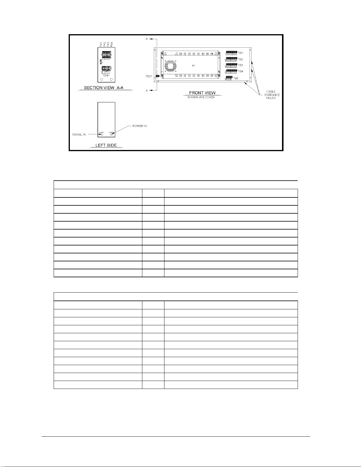
Figure 7: Time & Temp. Enclosure
Digit 1
Driver Designation/Color TB1 Lampbank Designation (Existing)/Color
F41 BLK 1 Common BLK, BRN (2 wires)
NC 2 NC
J5-2 RED 3 Seg. A RED
J1-3 BRN 4 Seg. B ORN
J1-6 TAN 5 NC (ID Light Control)
J1-5 PNK 6 NC (Front Light Control)
J1-9 VIO 7 Seg. E YEL
J5-1 ORN 8 Seg. F GRN
J5-4 BLU 9 NC
J5-8 GRY 10 Seg. H BLU
Digit 2
Driver Designation/Color TB2 Lampbank Designation (Existing)/Color
F42 BLK 1 Common VIO, GRY (2 wires)
NC 2 NC
J2-3 BRN 3 Seg. A WHT
J2-2 RED 4 Seg. B WHT/BLK
J2-1 ORN 5 Seg. C WHT/BRN
J2-6 TAN 6 Seg. D WHT/RED
J6-5 PNK 7 Seg. E WHT/ORN
J6-4 BLU 8 Seg. F WHT/YEL
J6-9 VIO 9 Seg. G WHT/GRN
J6-8 GRY 10 Seg. H WHT/BLU
D-2
Appendix D: Update Triac
Time & Temperature
Page 75
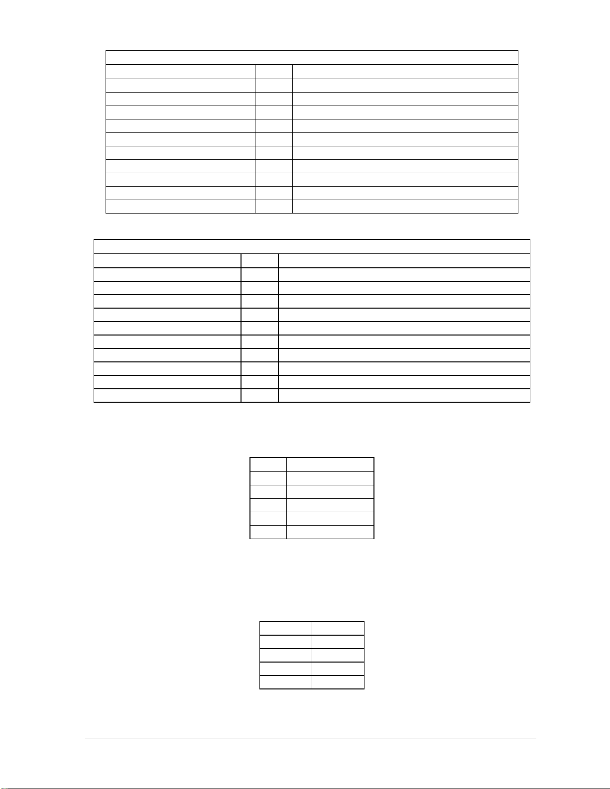
Digit 3
Driver Designation/Color TB3 Lampbank Designation (Existing)/Color
F43 RED 1 Common WHT/VIO, WHT/GRY (2 Wires)
NC 2 NC
J11-3 BRN 3 Seg. A WHT/BLK/BRN
J11-2 RED 4 Seg. B WHT/BLK/RED
J11-1 ORN 5 Seg. C WHT/BLK/ORN
J11-6 TAN 6 Seg. D WHT/BLK/YEL
J15-5 PNK 7 Seg. E WHT/BLK/GRN
J15-4 BLU 8 Seg. F WHT/BLK/BLU
J15-9 VIO 9 Seg. G WHT/BLK/VIO
J15-8 GRY 10 Seg. H WHT/BLK/GRY
Digit 4
Driver Designation/Color TB4 Lampbank Designation (Existing)/Color
F44 RED 1
Common WHT/BRN/RED, WHT/BRN/ORG (2 Wires)
NC 2 NC
J12-3 BRN 3 Seg. A WHT/BRN/YEL
J12-2 RED 4 Seg. B WHT/BRN/GRN
J12-1 ORN 5 Seg. C WHT/BRN/BLU
J12-6 TAN 6 Seg. D WHT/BRN/VIO
J16-5 PNK 7 Seg. E WHT/BRN/GRY
J16-4 BLU 8 Seg. F WHT/RED/ORN
J16-9 VIO 9 Seg. G WHT/RED/YEL
J16-8 GRY 10 Seg. H WHT/RED/GRN
4. Route the photo/temperature sensor cable through one of the cable entrance holes
on the right side of the new chassis and terminate as shown below.
TB5 Sensor Cable
1 WHT
2 BLK
3 RED
4 BRN
5 GRN
5. Route the power through the cable entrance hole on the left side labeled “Power
In.” Conduit may be used to route the cable to the hole. Be sure to follow all
local electrical codes. Power must be 120/240 VAC single phase.
6. Connect power to the terminal block (TB41) and the grounding lug (E41) as
shown below:
TB41 1 Line 1
TB41 2 Neut
TB41 3 Neut
TB41 4 Line 2
E41 Gnd
Appendix D: Update Triac
Time & Temperature
D-3
Page 76

D.1.3 Controller Installation
The controller need not be located near the display driver assembly. However, two
cables must be connected between the indoor controller and the display driver
assembly. Refer to Figure 8 and Drawing B -99250.
1. Open the controller enclosure by removing the four (4) screws from the blank end
panel and sliding the top cover panel out.
2. Set SW6 and SW8 to on position for indoor control and 7/8 segment mode. (refer
to Drawing A-87841 in Section 3 for switch location)
3. Route the 2-cond. cable (Daktronics part number W-1077) through the grommet
labeled “SIGNAL” and connect to TB1 on the controller (refer to Figure 8 and
Drawing A-59425 and A-87845 in Appendix A). Pins 1 and 2 are red and
black respectively.
4. Refer to Figure 8 to determine the location of TB31. Connect the opposite end
of the cable to the un-used side of TB31. Pins 1 and 2 are red and black
respectively.
5. Route the 5-cond. cable (Daktronics part number W-1007) through the grommet
labeled “SIGNAL” and connect to TB2 on the controller. Wire the colors per
Drawing A-59425 and A-87845 in Apppendix A.
6. Refer to Figure 8 to determine the location of TB5. Connect the opposite end of
the cable to TB5 matching existing colors.
7. Plug one end of the 25 foot, grey modular cable into the DataTime hand held
console.
8. Plug the opposite end into jack labeled “Console” on the controller enclosure, and
close enclosure, by following step 1 in reverse order.
9. Plug the wall transformer cord into the jack labeled “Power 12 VAC” on the
controller enclosure.
10. Plug the wall transformer into the outlet. On power-up, the console LCD should
display the word “DATATIME” for a few seconds, shows the software revision
number, then start cycling through the programmed sequence of time and/or
temperature and/or price.
Figure 8: Connections from Controller
D-4
Appendix D: Update Triac
Time & Temperature
Page 77

D.1.4 Temperature/Light Sensor Installation
Refer to Section 3.5.
D.2 Operation
Refer to Section 4 for operating instructions and to Section A.3 for indoor console use.
Note: SW8 to SW6 must be ON. Refer to Section 4.3 (7/8 segment mode) for this update.
D.3 Troubleshooting
Troubleshooting of the controller can be done with the hand-held console. If the console is
operating and displaying correctly, then the controller is most likely operating properly. Refer to
the display manual for troubleshooting the display.
D.4 Replacement Parts
Part Description Daktronics Part No.
Data Time 50 Update Controller 0P-1114-0001
Indoor Hand Held Console 0A -1114-0020
Console Cable W-1265
Wall Transformer 0A -1065-0022
Lamp Driver 0A -1033-0100
Appendix D: Update Triac
Time & Temperature
D-5
Page 78

Page 79
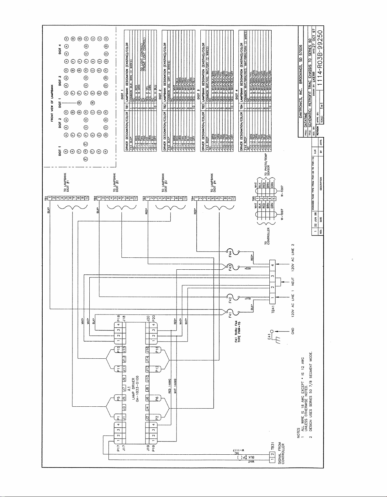
Page 80

 Loading...