

Page 1

Daktronics Data Manager
(DDM) Software
Operation Manual
DD1376354 Rev 2 – 2 October 2014
201 Daktronics Drive PO Box 5128 Brookings, SD 57006-5128
Tel: 1-800-DAKTRONICS (1-800-325-8766) Fax: 605-697-4700
Web: www.daktronics.com/support
Page 2

Page 3

DD1376354
Rev 2 – 2 October 2014
DAKTRONICS, INC.
Copyright 2008-2014
All rights reserved. While every precaution has been taken in the preparation of this manual, the publisher
assumes no responsibility for errors or omissions. No part of this book covered by the copyrights hereon may be
reproduced or copied in any form or by any means – graphic, electronic or mechanical, including photocopying,
taping or information storage and retrieval systems – without written permission of the publisher.
All trademarks used in this manual are property of their respective owners.
Page 4

Page 5

Table of Contents
Section 1:Introduction.......................................................................................................................... 1
1.1 System Requirements ............................................................................................................. 1
1.2 Software Conventions ............................................................................................................ 1
Section 2:Installation & Registration .................................................................................................. 3
2.1 Installation................................................................................................................................ 3
2.2 Opening & Exiting the Application ...................................................................................... 3
2.3 Registration .............................................................................................................................. 3
Section 3:Operation .............................................................................................................................. 5
3.1 Main Application Screen ........................................................................................................ 5
3.2 Document Actions Task Pane ................................................................................................ 6
Enabling Document Actions ........................................................................................... 6
View ................................................................................................................................... 7
Package Suite Editor ........................................................................................................ 7
Port Configuration ........................................................................................................... 7
Function Button Configuration ...................................................................................... 8
Creating Function Buttons ....................................................................................... 9
Paging Function Buttons .......................................................................................... 9
Scrolling Function Buttons..................................................................................... 10
Sorting ...................................................................................................................... 10
Grouping Function Buttons ................................................................................... 10
Select Current Function Buttons ........................................................................... 10
Start Sequence Function Buttons .......................................................................... 11
Blank Sign Function Buttons ................................................................................. 11
Start Schedule Function Buttons ........................................................................... 11
End Schedule Function Buttons ............................................................................ 12
Sign Dimming Function Buttons........................................................................... 12
Refresh Data Function Buttons ............................................................................. 12
Select Frame Function Buttons .............................................................................. 12
Capture RTD Function Buttons ............................................................................. 12
ITF Configuration .......................................................................................................... 13
Help ................................................................................................................................. 13
Columns .......................................................................................................................... 14
Data Range Location ...................................................................................................... 14
Highlight Color .............................................................................................................. 15
Input Mapping ............................................................................................................... 15
Row Count ...................................................................................................................... 15
Input & Output Monitors.............................................................................................. 15
3.3 Outputting Data .................................................................................................................... 16
3.4 Advanced Data Importing ................................................................................................... 17
Packages .......................................................................................................................... 17
Create a Package Suite ........................................................................................... 17
Create an Input Port ............................................................................................... 19
Input Mapping ........................................................................................................ 19
Final Note on Package Suites ................................................................................ 19
Web Queries ................................................................................................................... 20
Table of Contents i
Page 6

Appendix A:Sample DDM Exercise ................................................................................................... 21
Creating Headers ................................................................................................................................. 22
Creating an Output Port ..................................................................................................................... 23
Creating Function Buttons.................................................................................................................. 24
Stop Button...................................................................................................................... 24
Paging Button ................................................................................................................. 24
Scrolling Button .............................................................................................................. 25
Scrolling Button with Sorting ....................................................................................... 25
Creating the ITF ................................................................................................................................... 27
Entering & Sending Data .................................................................................................................... 27
ii Table of Contents
Page 7

Section 1: Introduction
Bold
Indicates an item that requires direct action, such as clicking, pressing,
selecting or formatting.
Italics
Indicates onscreen text or labels that are not clickable.
Bold Italics
Used to reference items within the manual, such as figures or sections, as
well as other documents and important notes.
[X]
Represents a keyboard key that needs to be pressed.
“Quotes”
Text or commands that may be typed; also indicate file or folder names
Click
Press and release the left mouse button.
Double-click
Press and release the left mouse button twice.
Right-click
Press and release the right mouse button.
Select
Highlight or mark, such as by placing a check mark in a nearby box;
clicking will not necessarily perform an action.
>
Followed by, as in menu navigation (ex. File > Open).
The purpose of this manual is to assist users with the installation and operation of the Daktronics
Data Manager (DDM) application. The DDM application is a plug-in for Microsoft® Office Excel® that
converts data from spreadsheets into formats used by Daktronics display control systems. Once the
data entered in a spreadsheet is outputted as Real Time Data (RTD), it can easily be sent to displays.
The manual is divided into four sections: Introduction, Installation, Operation, and Appendix.
Introduction covers the basic information about the application and this manual. Take time
to read the entire introduction as it explains concepts and conventions used throughout the
rest of the manual.
Installation describes the installation procedures of the DDM application.
Operation details the specific operation and configuration of the DDM application.
Appendix includes an exercise to help users create a basic DDM spreadsheet.
Daktronics identifies manuals by an ED or DD number located on the cover page of each
manual. Any manuals referenced in this document will be identified by its ED or DD number.
For example, this manual would be referred to as DD1376354.
1.1 System Requirements
The DDM application has the following system requirements:
Windows XP or higher Operating System
Microsoft
CPU and RAM must at least be equal to minimum requirements of operating system
Additional serial ports or networking may be needed based on interface requirements
The DDM application will typically be loaded onto a computer system that already contains
other Daktronics software, such as the Daktronics display controllers; however, it may also be
installed on a different computer on the same network.
Excel 2003 Professional or better
1.2 Software Conventions
This manual contains the following software conventions and terminology:
Introduction 1
Page 8

Page 9
Section 2: Installation & Registration
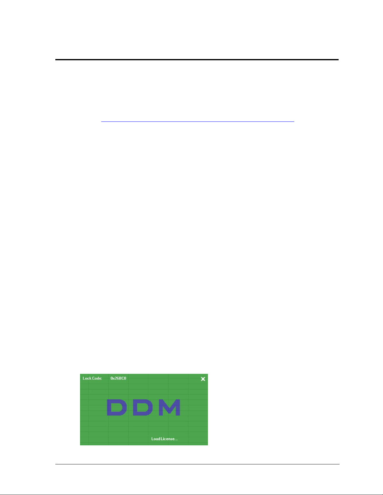
Figure 1: Registration Window
2.1 Installation
To install the DDM application:
1. Download and save the “DDM.zip” file from
http://dakfiles.daktronics.com/downloads/Sports_Products/DDM/.
2. Extract the contents of the “DDM.zip” file.
3. Double-click the “setup” file to begin the installation procedure.
4. Follow the onscreen instructions.
5. Click Close when done.
2.2 Opening & Exiting the Application
To open the application:
1. Navigate to “C:\Program Files\Daktronics\DDM” (Windows XP) or
“C:\Program Files (x86)\Daktronics\DDM” (Windows 7 +).
2. Copy the “DDM.xls” Excel Worksheet file.
3. Create a new folder in a different location, such as the “Desktop” or “My
Documents”, and Paste the “DDM.xls” Excel Worksheet file into the new folder.
4. Double-click the “DDM.xls” Excel Worksheet file inside the new folder.
Note: It is possible to open the DDM worksheet right from the “Program Files” folder.
However, going through the above process will prevent the original DDM worksheet
from being overwritten, and a clean copy will always be available to make new
worksheets later on.
To exit the application:
Click the top exit button in the upper-right corner of the window to close the Excel
application completely.
Click the bottom exit button in the upper-right corner to close only the DDM
spreadsheet.
Hold [Alt] and press [F4].
2.3 Registration
When the DDM application is first opened, the registration screen will appear (Figure 1).
A new software license file must be obtained using the given Lock Code.
Installation 3
Page 10

The registration process varies depending on the operating system in use:
Windows XP
1. Open a DDM spreadsheet as described in Section 2.2.
2. Write down the Lock Code, and exit the DDM spreadsheet.
3. Email the Lock Code to DakStats@daktronics.com with the subject line “DDM Lock
Code”, and a software license file will be emailed back upon proof of purchase.
4. Save the software license file to “C:\Program Files\Daktronics\DDM”.
5. Reopen the DDM spreadsheet. The license file will load automatically and unlock the
application for use.
Windows 7 +
1. Set Excel to Run as administrator by right-clicking the “EXCEL.exe” file located in
“C:\Program Files (x86)\Microsoft Office\Office##”.
2. From within Excel, press [Ctrl] + [O] and navigate to the “DDM.xls” file to open.
The default location is in “C:\Program Files (x86)\Daktronics\DDM”; however, it is
recommended that a backup copy first be saved elsewhere.
3. Write down the Lock Code, and exit the DDM spreadsheet.
4. Email the Lock Code to DakStats@daktronics.com with the subject line “DDM Lock
Code”, and a software license file will be emailed back upon proof of purchase.
5. Save the software license file to “C:\Program Files (x86)\Daktronics\DDM”.
6. Reopen the DDM spreadsheet, and the license file will load automatically to unlock
the application for use.
7. Close out of Excel. It should now be possible to double-click a DDM spreadsheet to
open it without having to run Excel as an administrator.
Note: The DDM application will not become functional without a software license. If the
DDM application is not registered, be sure to close the DDM spreadsheet, or it will not be
possible to open any other spreadsheets.
4 Installation
Page 11
Section 3: Operation
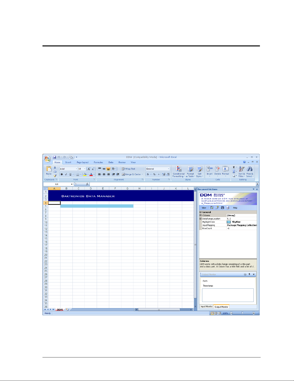
Figure 2: DDM Main Application Screen (Excel 2007)
The operation of the DDM application depends largely on the user’s familiarity with Microsoft Excel.
For assistance using Microsoft Excel, please refer to the Microsoft Office Excel Help by pressing [F1].
With a little practice, it will be possible to output data to a display as easily as using ordinary
Microsoft Excel spreadsheets.
This section of the manual on program operation is broken into three main sections:
The Main Application Screen
Document Actions Task Pane
Advanced Data Importing
3.1 Main Application Screen
After the DDM application is registered, the main application screen will appear (Figure 2).
This screen contains all the menus and buttons as a typical Excel spreadsheet. Every setting
related to outputting information to a display is found in the Document Actions task pane.
By default, there are six cells of the spreadsheet highlighted in blue. Any data entered outside
of the highlighted columns will not be included as Real Time Data (RTD). The extra space
may be used for labels or notes about what data should be included in the spreadsheet.
Operation 5
Page 12

3.2 Document Actions Task Pane
Figure 3: Document Actions
Figure 4: Enabling Document Actions
Figure 5: Enabling the Task Pane
(Excel 2003)
Figure 6: Enabling Document Actions
(Excel 2003)
The Document Actions task pane (Figure 3) displays all the settings to output RTD from the
information that was typed or imported into the spreadsheet.
Enabling Document Actions
The Document Actions task pane is opened by
default. If the task pane is closed, go to View >
Document Actions to turn it back on in newer
versions of Microsoft Excel (Figure 4).
Note: For Microsoft Excel 2003, go to View >
Toolbars > Task Pane (Figure 5). It may also
be necessary to click the down arrow on the
Task Pane, and then select Document Actions
(Figure 6).
6 Operation
Page 13

The Document Actions task pane contains the following six buttons:
Figure 7: View Button
Figure 8: Port Configuration Window
1) 2) 3) 4) 5) 6)
1) View
2) Package Suite Editor
3) Port Configuration
4) Function Button Configuration
5) ITF Configuration
6) Help
In addition to buttons, the Document Actions task pane also includes five configuration boxes:
Columns
Data Range Location
Highlight Color
Input Mapping
Row Count
View
Click the View button (Figure 7)
to enable or disable the Input and
Output Monitor toolbars (see
Input & Output Monitors).
Package Suite Editor
Click the Package Suite Editor button to open a window to import packages of data into
the spreadsheet from an external data source (see Advanced Data Importing).
Port Configuration
Click the Port Configuration button to open a window to set up ports for sending or
receiving data (Figure 8).
Operation 7
Page 14

1. Click Add to insert a new port.
Figure 9: Function Button Configuration Window
2. Under the General header, adjust the following options to set up the new port:
Format: Set to ERTD for outputting data to Daktronics displays.
Name: Type in a descriptive name for the port.
Protocol: Select the method of data transfer from Serial, Tcp, or Udp.
Note: Additional settings will appear based on the chosen connection.
Contact the network administrator to apply the appropriate settings.
Suite: Assign a package suite if applicable (see Advanced Data Importing).
Type: Select Tx if the port will be used to send out data or Rx if the port will
be receiving data.
3. Click Ok when finished.
Function Button Configuration
Click the Function Button Configuration button to open a window to set up buttons for
starting and stopping data output as well as advanced display control commands (Figure 9).
Note: Each DDM spreadsheet file has a corresponding “DDM.cfg” configuration file located
in the same directory. If a directory has multiple spreadsheet files, they will read from the
same configuration file and share the same buttons. It is recommended to keep each DDM
spreadsheet file in its own folder to prevent function buttons from being overwritten.
8 Operation
Page 15

Creating Function Buttons
Figure 10: Script Editor Window
1. On the Function Button Configuration window, select a worksheet (Range) for which
the buttons will be used.
2. Click Add to insert a new function button.
3. Click Command Collection, and then click the button to open the Script Editor window.
4. Click Add to insert a new command.
5. Under Type, click the arrow to choose from a list of command types (Figure 10).
Multiple command types may be assigned to a single button as long as the actions do
not negate each other.
6. Select StopAutoSending, and then click Ok.
7. Change the Name of the function button to “Stop”.
Note: Every DDM spreadsheet file must include a button to stop sending data and one or
more buttons to resume sending data. Other display controls may be configured as needed.
Paging Function Buttons
Paging function buttons send out pages of RTD with a predefined number of rows of
information on each page.
1. Repeat steps 1 – 5 under Creating Function Buttons.
2. Select Paging from the list of command types.
3. Adjust the following settings accordingly:
HoldingTime: Type in how many seconds to wait before sending the next data set.
Port: Select a previously configured port (see Port Configuration).
RecordCount: Type in how many rows of data should be sent out at a time.
Sorts: Sort text or numerical data in ascending or descending order before it is
sent out (See Sorting).
4. Click Ok when finished.
5. Give the Paging function button a descriptive Name.
Note: Both Paging and Scrolling will send out data until the first empty row of data, and
then start from the top again. To allow blank rows to be sent, there must be at least one
cell in that row with a dummy character (such as a space) in order for it to appear to be
empty. Otherwise when the DDM application finds a row with absolutely no data, it will
disregard any information following the empty row.
Operation 9
Page 16

Scrolling Function Buttons
Figure 11: Sorting
Scrolling function buttons send out RTD line by line with the next piece of data moving into
the previous spot until all of the information has gone through.
1. Repeat steps 1 – 5 under Creating Function Buttons.
2. Select Scrolling from the list of command types.
3. Adjust the following settings accordingly:
HoldingTime: Type in how many seconds to wait before sending the next data set.
Port: Select a previously configured port (see Port Configuration).
RecordCount: Type in how many rows of data should be sent out at a time.
Sorts: Sort text or numerical data in ascending or descending order before it is
sent out (See Sorting).
4. Click Ok when finished.
5. Give the Scrolling function button a descriptive Name.
Sorting
When creating Paging and Scrolling function
buttons, users are given the option to sort the data
before it is sent out (Figure 11). Sorting ensures that
data will always be displayed in a specific way,
regardless of how it appears in the spreadsheet.
First/Second/ThirdSort: Select the header
name of the column that includes the data
that will be used as the criteria for sorting.
First/Second/ThirdSortOrder: Select Ascending (Asc) or Descending (Desc) sort orders.
Up to three columns can be used to determine how data is sorted. This is useful in cases of
duplicate information in a column. For example, if two people have the same last name in a
column of names that are sorted alphabetically (FirstSort), then a column with their first
names could be used to determine the next sort order (SecondSort).
Grouping Function Buttons
Grouping function buttons send out multiple rows of data based on the first selected row.
1. Repeat steps 1 – 5 under Creating Function Buttons.
2. Select Grouping from the list of command types.
3. Adjust the following settings accordingly:
Port: Select a previously configured port (see Port Configuration).
RecordCount: Type in how many rows of data should be sent out at a time.
4. Click Ok when finished.
5. Give the Grouping function button a descriptive Name.
Select Current Function Buttons
A Select Current function button allows users to select a row that will always be visible
even if it is not due up to be displayed in the main scrolling, paging, or grouping order.
The Select Current function button is also used to choose a location to import data
(see Advanced Data Importing).
1. Repeat steps 1 – 5 under Creating Function Buttons.
2. Select SelectCurrent from the list of command types.
3. Click Ok when finished.
4. Give the Select Current function button a descriptive Name.
10 Operation
Page 17

Note: The buttons on the following two page are optional commands for the display controllers.
These buttons are not needed to output data from the DDM application.
Start Sequence Function Buttons
Start Sequence function buttons start sequences on selected signs. Sequences (Presentations)
control the arrangement and appearance of graphics and data on a display. Refer to the
documentation provided with the Daktronics display control software for more information
on creating sequences.
1. Repeat steps 1 – 5 under Creating Function Buttons.
2. Select StartSequence from the list of command types.
3. Adjust the following settings accordingly:
Mode: Select from Continuous, SingleStep, or SelectedFrame play modes.
Port: Select a previously configured port (see Port Configuration).
Sequence: Type in the Drive letter, Frame number, Library name, and Sequence
name for the sequence to start.
SignNumber: Type in the sign number for the sign on which the selected sequence
should be started.
Times: Select the number of times to display the sequence.
4. Click Ok when finished.
5. Give the Start Sequence function button a descriptive Name.
Blank Sign Function Buttons
Blank Sign function buttons clear the data from selected signs.
1. Repeat steps 1 – 5 under Creating Function Buttons.
2. Select BlankSign from the list of command types.
3. Adjust the following settings accordingly:
Port: Select a previously configured port (see Port Configuration).
SignNumber: Type in the sign number for the sign to be blanked.
4. Click Ok when finished.
5. Give the Blank Sign function button a descriptive Name.
Start Schedule Function Buttons
Start Schedule function buttons start schedules on selected signs. Refer to the documentation
provided with the Daktronics display control software for more information on creating schedules.
1. Repeat steps 1 – 5 under Creating Function Buttons.
2. Select StartSchedule from the list of command types.
3. Adjust the following settings accordingly:
Port: Select a previously configured port (see Port Configuration).
Schedule: Type in the Drive letter, Frame number, Library name, and Sequence name
for the schedule to start.
SignNumber: Type in the sign number for the sign on which the selected schedule
should be started.
4. Click Ok when finished.
5. Give the Start Schedule function button a descriptive Name.
Operation 11
Page 18

End Schedule Function Buttons
End Schedule function buttons stop schedules from running on a sign.
1. Repeat steps 1 – 5 under Creating Function Buttons.
2. Select EndSchedule from the list of command types.
3. Adjust the following settings accordingly:
Port: Select a previously configured port (see Port Configuration).
SignNumber: Type in the sign number for the sign that should stop running
schedules.
4. Click Ok when finished.
5. Give the End Schedule function button a descriptive Name.
Sign Dimming Function Buttons
Sign Dimming function buttons control the brightness levels of selected signs. Refer to the
documentation provided with the Daktronics display control software for more information
on dimming controls.
1. Repeat steps 1 – 5 under Creating Function Buttons.
2. Select SignDimming from the list of command types.
3. Adjust the following settings accordingly:
Dimming: Select from ManualDim, ManualBright, PhotocellDetect,
PhotocellRemote, or ScheduleDimming.
Port: Select a previously configured port (see Port Configuration).
SignNumber: Type in the sign number for the sign to have dimming control.
4. Click Ok when finished.
5. Give the Sign Dimming function button a descriptive Name.
Refresh Data Function Buttons
Refresh Data function buttons resend data before the hold time has passed.
1. Repeat steps 1 – 5 under Creating Function Buttons.
2. Select RefreshData from the list of command types.
3. Click Ok when finished.
4. Give the Refresh function button a descriptive Name.
Select Frame Function Buttons
Select frame function buttons play only a selected frame within a currently playing sequence.
1. Repeat steps 1 – 5 under Creating Function Buttons.
2. Select SelectFrame from the list of command types.
3. Adjust the following settings accordingly:
FrameNumber: Type in the number of the frame to play in the current sequence.
Port: Select a previously configured port (see Port Configuration).
SignNumber: Type in the sign number for the sign that contains the selected frame.
4. Click Ok when finished.
5. Give the Select Frame function button a descriptive Name.
Capture RTD Function Buttons
Capture RTD function buttons are used primarily for in-house testing purposes. These
function buttons store the current frame buffer data into a secondary capture buffer that can
be recalled at a later time.
12 Operation
Page 19

ITF Configuration
Figure 12: ITF Configuration
Figure 13: Help Button
Click the ITF Configuration button to open a window to set up an Input Template File
(Figure 12). An ITF is the link between the display controller and the information that is
entered in the spreadsheet.
1. Select a Data Stream (worksheet).
2. Click OK.
3. Save the ITF with a descriptive name.
4. The ITF will then be used by the display controller to gather RTD from the
spreadsheet.
Note: An ITF must be saved before data can be sent to a display controller and after the
following actions are performed:
Adding or removing Headers
Modifying the Size of a data field
Modifying the Title of a data field
Adding, removing, or modifying function buttons
Help
Click the Help button to see information about the version of the DDM application that is
currently installed and to open the instruction manual (Figure 13).
Operation 13
Page 20

Columns
Figure 14: Header Editor Window
Figure 15: Data Range Location
This configuration box sets the number of highlighted columns in the data field, as well as the
maximum number of characters for each piece of data in the column. Click the plus (+) and
minus (-) signs to expand or hide the options, respectively.
1. Click Columns, and then click the button that appears to open the Header Editor
window (Figure 14).
2. Click Add to insert more columns, and click Remove to delete columns.
3. Select a maximum Size in characters for the information in each cell for the column.
Note: If information appears to be getting cut off on the display, make sure that the
Size is large enough to fit the whole piece of information. Resizing column width to
see longer information is not the same as changing the Size.
4. Enter a Title for the column. The Title will show up as the column header in the RTD.
5. Click Ok when finished.
Data Range Location
This configuration box sets the starting location of the headers on the spreadsheet (Figure 15).
Click the plus (+) and minus (-) signs to expand or hide the options, respectively. Be sure to
adjust this setting before entering data into the spreadsheet cells.
14 Operation
Page 21

Highlight Color
Figure 16: Highlight Color
Figure 17: Input & Output Monitors
This configuration box is used to change the color of column
headers. Click HighlightColor, and then click the arrow to select
from a wide variety of preset colors (Figure 16).
Note: Changing the highlight color, text colors, and text
sizes or fonts will not affect their appearance on the display.
Input Mapping
This configuration box is used to define what input package
fields are to be displayed in which cells of the spreadsheet. See
Advanced Data Importing for more information about package
suites and input mapping.
Row Count
This configuration box is used to define the total number of rows in a column, not counting
the header. If the final number of rows in a column is unknown, leave the Row Count value
set to “-1” and the first empty row will be used to determine the actual row count.
Input & Output Monitors
The bottom of the Document Actions task pane displays both an Input Monitor and an Output
Monitor (Figure 17). These toolbars are used to detect problems in receiving or sending data.
Each toolbar shows the port that data is traveling through, the last time the data was sent or
received, and the data itself.
The toolbars can be rearranged or removed entirely:
Click the Toggle Tabs button to view both monitors side by side.
Click the Auto Hide button to minimize one or both monitors.
Click the Close button to remove one or both monitors from the Document
Click and drag the monitor toolbars to move them anywhere on the screen.
Note: For newer versions of Excel, the data monitor window may have a black background
with black text, so it appears as if nothing is outputting. To confirm that data is in fact being
sent out, click and drag on the text in this box.
Operation 15
Actions task pane. Use the View button to bring them back.
Page 22

3.3 Outputting Data
Figure 18: Function Buttons Toolbar (Add-Ins Tab)
Figure 19: Function Button Toolbar (Excel 2003)
After function buttons have been created, a new tab called Add-Ins will appear at the top of
the screen in newer versions of Microsoft Excel (Figure 18). Use this tab to access all of the
available function buttons.
Note: In Microsoft Excel 2003, the
buttons will be in the bottom left
corner of the screen (Figure 19). If the
buttons do not appear at first, re-open
the Function Button Configuration
screen, and click OK.
1. Enter data into the spreadsheet as normal. Be sure to utilize the formulas and
features available in Microsoft Excel for creating spreadsheets.
2. When it is time to output the data:
Click a Paging or Scrolling function button to begin continually sending out
information across the port assigned to the button. The worksheet tab will turn
from red to flashing green, and data will appear in the Output Monitor.
Click the Select Current button to highlight a selected row in gray. The current
row data will only be sent out if the rest of the data is already Paging or Scrolling.
If there is no data in a selected row, the current row fields will be left blank. The
worksheet tab will remain red after the button is clicked by itself, or it will
remain green if a Scrolling or Paging button was clicked first.
Click a Grouping function button to send out information across the assigned
port only if valid data has been selected. Grouping buttons can be clicked
independently or while data is still Scrolling or Paging. The worksheet tab will
remain red after the button is clicked by itself, or it will remain green if a
Scrolling or Paging button was clicked first.
Click the StopAutoSending function button to stop sending out information. The
worksheet tab will become red again.
Note: It is not necessary to stop sending out data to modify it. Simply type in the changes
on-the-fly and they will appear in the next data cycle.
16 Operation
Page 23

3.4 Advanced Data Importing
Figure 20: Package Suite Editor Window
Figure 21: PackageSetting Collection Editor Window
Packages
Packages tell the DDM application what types of incoming data to look out for, similar to
what an ITF does for the display controller. Incoming data sources will typically include other
Daktronics products, such as an All Sport® controller, for scoring and timing information.
In order to utilize packages for importing data, there are three major steps to complete:
1. Create a Package Suite
2. Create an Input Port
3. Input Mapping
Create a Package Suite
1. Click the Package Suite Editor button .
2. Click Add to insert a new package suite (Figure 20).
3. Type a descriptive Name for the package suite.
4. Leave Type set to Ascii.
5. Click Package Collection, and then click the button to open the PackageSetting
Collection Editor window (Figure 21).
Operation 17
Page 24

a. Click Add to insert a new package to the package suite.
Figure 22: PackageFieldSetting Collection Editor Window
b. Type in a descriptive Name for the package.
c. Import an ITF, or manually create the data fields:
Import Fields
1) Click Import and then click the button to locate and Open an ITF.
A list of Fields will automatically be populated based on the ITF.
2) Click OK to return to the Package Suite Editor window (Figure 20).
Create Fields
1) Click Field Collection and then click the button to open the
PackageFieldSetting Collection Editor window.
2) Click Add to insert a new field to the package (Figure 22).
3) In the Mask cell, type in one or more of the following symbols to
represent each character of the expected incoming data:
Use an asterisk (*) for any number or letter.
Use a pound sign (#) for a number from 0-9 only.
Use a question mark (?) for a letter only.
To use one of the above characters or other special characters instead
of a number or letter, place a quote (“) before the character.
Note: The first Field should contain definite letters or numbers that
uniquely identify the data as the start of a new incoming packet.
4) Type in a descriptive Name for the field.
5) Add as many fields as needed to receive every piece of desired data.
6) Click OK twice to return to the Package Suite Editor window (Figure 20).
6. On the Package Suite Editor window, it is possible to view and modify the current
package and field settings using the plus (+) and minus (-) signs.
7. Click Ok when finished.
18 Operation
Page 25

Create an Input Port
Figure 23: Data Mapping Editor Window
1. Click the Port Configuration button .
2. Click Add to insert a new port.
3. Adjust the following options to set up an input port:
Format: Select ERTD if using an imported ITF. Select CUSTOM if the fields were
created manually.
Name: Type in a descriptive name for the port
Protocol: Select the method of data transfer from Serial, Tcp, or Udp.
Note: Additional settings will appear based on the chosen connection.
Contact the network administrator to apply the appropriate settings.
Suite: Select a package suite.
Type: Select Rx.
4. Click Ok when finished.
Input Mapping
1. Click InputMapping, and
then click the button to
open the Data Mapping
Editor window.
2. Click Add to insert a new
Package Mapping List
(Figure 23).
3. Select a Package.
4. Select a Type:
Overwriting: Used only
with a Select Current
button. Imported data
will be populated in a
selected row. Make
sure the previous row
also contains data.
Mapping: Rows will be
populated with data from the input package based on a predefined Key.
5. Click the plus sign (+) next to Mappings to see a list of each column in the
spreadsheet.
6. Click the plus sign (+) next to the column number.
Field: Select a data field from the chosen package that will go in the column.
Key: Used only for Mapping. When a field key is set to True, the DDM application
will not create another row out of the incoming data, but will instead update the
other cells in the row containing data that matches the incoming data’s key fields.
7. Click Ok when finished.
Final Note on Package Suites
If the package suites do not seem to be working correctly, contact Daktronics to create custom
configuration files to suit the particular data importing needs.
Operation 19
Page 26

Web Queries
Figure 24: Import Data From Web
Figure 25: New Web Query (Excel 2003)
Figure 26: Refresh Control
It is possible to output information to a display that was retrieved from the Internet by using
a built-in feature of Microsoft Excel called a Web Query. This feature is useful for displaying
news stories, stock quotes, out-of-town scores, and many other types of information that are
frequently updated over the Internet. For more information about web queries, please refer to
the Microsoft Office Excel Help by pressing [F1].
1. Select the cell(s) where the imported
information will go.
2. In newer versions of Microsoft Excel,
click the Data tab, and then click
From Web (Figure 24).
Note: In Microsoft Excel 2003, go to
Data > Import External Data >
New Web Query (Figure 25).
3. The New Web Query window will
appear, which acts as a web
browser inside Microsoft Excel.
Type in or Paste the address to the
site where the data will be gathered.
4. Once at the desired webpage, click a
yellow arrow and it will change
to a green check mark . Data
within the blue highlighted area will
be imported into the spreadsheet.
Note: When gathering data from the
Internet, it is very important to
identify the source of the
information to avoid plagiarism and
violating copyright laws. When in
doubt, contact the author to ask for permission to use the data. Be sure to include the
author of the information on the display if it is someone other than the software user.
5. Click Import.
6. On the Import Data window, select the cell destination for the imported data if needed.
7. Click the Properties button to adjust the settings of the imported data, in particular the
Refresh control (Figure 26).
8. When the import properties and location are correct, click OK. Depending on the size of
the data table, it may take a few moments to import the data into the spreadsheet.
9. Be sure to update the number and size of the Columns to match the imported data, and
then save the ITF.
20 Operation
Page 27

Appendix A: Sample DDM Exercise
The following exercise will explain how to create a spreadsheet that contains a basic table of first and
last names and output the information as Real Time Data. This exercise is designed to familiarize
users with each step needed to output data from a spreadsheet.
At the end of the exercise, the DDM application will look similar to the following screen:
This exercise is broken into five main sections:
Creating Headers
Creating an Output Port
Creating Function Buttons
Creating the ITF
Entering & Sending Data
Appendix A 21
Page 28

Creating Headers
1. Click Columns in the Document Actions task pane, and then click the button.
2. In the Header Editor window, click Remove to delete Headers 3-6, so only Header 1 and Header
2 remain.
3. In the Title for Header 1, type in “First Name” and in the Title for Header 2, type in “Last
Name”. Leave the Size set to “25”, and then click Ok.
22 Appendix A
Page 29

Creating an Output Port
1. On the Document Actions task pane, click the Port Configuration button to open a
window to set up a port for transmitting data.
2. In the Port Configuration window, click Add to insert a new port, and then set up in the
following settings:
Format: Leave this option set to ERTD.
Name: Type in “Output Port”.
Protocol: For this example, choose Udp.
Suite: Leave this option blank
Type: Leave this option set to Tx for transmitting data.
Port: For this example, type in “21000”.
Note: When setting up a port, contact the network administrator to make sure these
settings are correct and do not interfere with the data ports of other Daktronics programs.
3. Click Ok when finished.
Appendix A 23
Page 30

Creating Function Buttons
On the Document Actions task pane, click the Function Button Configuration button to open a
window to set up the buttons for starting and stopping data output.
Stop Button
1. In the Function Button Configuration window, click Add to insert a new button.
2. Click Script, and then click the button to open the Script Editor window.
3. In the Script Editor window, click Add to insert a new command. Click Type, and then use the
drop-down arrow to select StopAutoSending.
4. Click Ok when finished, and then change the Name of the function button to “Stop”.
Paging Button
1. In the Function Button Configuration window, click Add to insert another function button.
2. Click Script, and then click the button to open the Script Editor window.
3. In the Script Editor window, click Add to insert a new command. Click Type, and then use the
drop-down arrow to select Paging.
4. Apply the following settings:
HoldingTime: Type in “2” to wait two seconds between sending the next data set.
Port: Select Output Port-Udp, 21000.
RecordCount: Type in “5” to send out five rows of data at one time.
Sorts: Leave this setting empty for now.
5. Click Ok when finished.
6. Name the function button “Paging”.
24 Appendix A
Page 31

Scrolling Button
1. In the Function Button Configuration window, click Add to insert another function button.
2. Click Script, and then click the button to open the Script Editor window.
3. In the Script Editor window, click Add to insert a new command. Click Type, and then use the
drop-down arrow to select Scrolling.
4. Apply the following settings:
HoldingTime: Type in “1” to wait one second between sending the next data set.
Port: Select Output Port-Udp, 21000.
RecordCount: Type in “10” to send out the first ten rows of data each time.
Sorts: Leave this setting empty for now.
5. Click Ok when finished.
6. Name the function button “Scrolling”.
Scrolling Button with Sorting
This example will only create a Scrolling button with sorting, but Paging buttons may be configured
with sorting as well.
1. In the Function Button Configuration window, click Add to insert another function button.
2. Click Script, and then click the button to open the Script Editor window.
3. In the Script Editor window, click Add to insert a new command. Click Type, and then use the
drop-down arrow to select Scrolling.
4. Apply the following settings:
HoldingTime: Type in “1” to wait one second between sending the next data set.
Port: Select Output Port-Udp, 21000.
RecordCount: Type in “10” to send out the first ten rows of data each time.
Sorts: Apply the following settings:
o FirstSort: Select Last Name (2).
o FirstSortOrder: Select Asc.
o SecondSort: Select First Name (1).
o SecondSortOrder: Select Asc.
Appendix A 25
Page 32

5. Click Ok when finished.
6. Name the function button “Scrolling with Sorting”.
The Function Button Configuration window should now look like this:
1. Click Ok when finished.
2. To locate the function buttons, click Add-Ins at the top of the screen in newer versions of
Microsoft Excel, or look in the bottom left corner of Microsoft Excel 2003.
26 Appendix A
Page 33

Creating the ITF
Creating an ITF is not necessary to complete this particular exercise. However, an ITF will be needed
to see how the information would look using a display controller.
1. Click the ITF Configuration button to open a window to set up an Input Template File.
2. Select DDM - Range 1 in the Data Stream drop-down box.
3. Click OK and Save the ITF with an easy to remember name in an easy to remember location,
preferably the same folder as the DDM spreadsheet file or directly in the display controller
program folder.
4. Refer to the Daktronics display controller software for information on creating display
sequences using Real-Time Data (RTD) fields.
Entering & Sending Data
1. Type any ten random names into the spreadsheet, with the First Name and Last Name
corresponding to the blue headers.
Note: The column widths may be widened to see the whole names if necessary, but make
sure no name exceeds 25 characters per cell.
2. Click the Paging button to begin sending out the list of
names. Since there are ten names and the button is set up to
send five rows at a time, there will be two pages of
information switching back and forth. Watch the Output
Monitor to see the information appear.
3. Now click the Scrolling button. Each name will appear and
move up one at a time until the first empty row and then
start over from the top.
Appendix A 27
Page 34

4. Now try clicking the Scrolling with Sorting button. Even
though the names in the spreadsheet are out of order, the
Output Monitor shows that they are now listed
alphabetically. Notice that if two people share the same last
name, the first names are listed in alphabetical order too
because of the SecondSort command.
5. Click the Stop button to stop sending out data from the
spreadsheet. The Output Monitor will display the last data
set that was successfully sent. It is not necessary to stop
sending out data to modify it. Simply type in the changes
on-the-fly and they will appear in the next data cycle.
Note: For newer versions of Excel, the data monitor window may have a black background
with black text, so it appears as if nothing is outputting:
To confirm that data is in fact being sent out, click and drag on the text in this box:
Also, the Timestamp field still notes the time of each successful transmission.
28 Appendix A
 Loading...