

Page 1
Auto Racing Display
Models CH-1036V & CH-1436V
Installation & Maintenance Manual
ED 8660
ED 8660
Project#1081
Rev. 2 - 19 August 1998
Copyright © 1995 Daktronics, Inc.
All rights reserved. While every precaution
has been taken in the preparation of this
manual, the publisher assumes no
responsibility for errors or omissions. No part
of this book covered by the copyrights
hereon may be reproduced or copied in any
form or by any means - graphic, electronic,
or mechanical, including photocopying,
taping, or information storage and retrieval
systems - without written permission of the
publisher.
DA
KTRONICS, INC.
Setting New Standards Worldwide
Page 2

P.O. Box 5128 331 32nd Ave. Brookings, SD 57006
Phone (605)697-4400 or (800) 843-9879 Fax 697-4444
2
Page 3

Table of Contents
1. Introduction .............................................................................................................1-1
1.1 How To Use This Manual ..........................................................................................1-1
1.2 Display Overview.......................................................................................................1-1
2. Installation ...............................................................................................................2-1
2.1 General System...........................................................................................................2-1
2.2 Display Mounting.......................................................................................................2-1
2.3 Control Signal Cable..................................................................................................2-1
2.4 Power Wiring .............................................................................................................2-2
2.5 Grounding...................................................................................................................2-2
2.5.1 New Power Installation.................................................................................2-2
2.5.2 Existing Power Installation ...........................................................................2-3
2.6 Lightning Protection...................................................................................................2-3
3. Maintenance & Troubleshooting............................................................................3-1
3.1 Lamp Replacement.....................................................................................................3-1
3.2 The Lamp Driver........................................................................................................3-1
3.3 Digit Segmentation.....................................................................................................3-2
3.4 Fuses...........................................................................................................................3-2
3.5 Schematic ...................................................................................................................3-2
3.6 Troubleshooting .........................................................................................................3-2
3.7 Replacement Parts List...............................................................................................3-3
3.8 Unit Exchange/Replacement Procedure.....................................................................3-3
Table of Contents
i
Page 4

Page 5
Section 1 : Introduction
1.1 How To Use This Manual
This manual explains the installation and maintenance of the Daktronics CH-1036V & CH1436V auto racing display systems. For questions regarding the safety, installation, operation or
service of this system, please refer to the telephone numbers listed on the cover page of this
manual.
Important Safeguards:
1. Read and understand these instructions before installing.
2. Do not drop the control console or allow it to get wet.
3. Be sure the display is properly grounded with a ground rod at the display location.
4. Disconnect power to the display when it is not in use.
5. Disconnect power when servicing the display.
6. Do not modify the display structure or attach any panels or coverings to the display
without the written consent of Daktronics, Inc.
The box below illustrates Daktronics drawing numbering system. The drawing number “7087P08A-69945” is how Daktronics identifies individual drawings. This number is located in the
lower-right corner of the drawing. This manual refers to drawings by listing the last set of digits
and the letter preceding them. In the example below, the drawing would be referred to as
Drawing A-69945. Referenced drawings are inserted at the end of the first section which
references them.
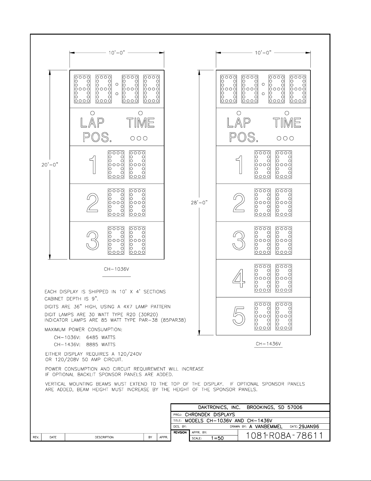
1.2 Display Overview
Reference Drawing: Models CH-1036V and CH-1436V ................Drawing A-78611
Refer to Drawing A-78611 for an illustration of the Daktronics CH-1036V and CH-1436V
displays. These displays along with the Daktronics CHTS-300 timing console will show the car
positions, time or lap number and the track status.
Introduction
1-1
Page 6
Page 7

Section 2 : Installation
2.1 General System
Reference Drawing: System Diagram, CH-1036V & CH-1436V....Drawing A-78612
Refer to Drawing A-78612 for a general system layout.
The general procedure for installing the CH-1036V or CH-1436V display is as follows:
1. Dig the footing holes and install beams and footings.
2. Route power and signal cables to the display and control locations.
3. Mount the displays to the beams as described in Section 2.2.
4. Route power and signal wires into the displays as described in Section 2.3 and 2.4.
2.2 Display Mounting
Reference Drawing: Scoreboard Mounting....................................Drawing A-55101
Refer to Drawing A-55101 for an example of a typical mounting for the display.
Note: The bolts that secure the display to the beams do not go through the beams but run
along both sides of the beam, clamping the display to the beams.
A mounting kit consisting of mounting angles, channels and 1/2" hardware is provided to
mount the display.
Each display consists of multiple sections. To install the display properly, the bottom section
should be attached first followed by the rest of the sections stacked above it. Refer to
Drawing A-55101 for installing each section. To install the display:
1. Position the display against the mounting beams to secure the bottom of the display to the
beams as shown.
2. Next, secure the top of the display. Once mounting angles are attached, the display may
be slid up or down to the desired height.
3. Once positioned as desired, tighten all the bolts.
2.3 Control Signal Cable
Reference Drawings: Color Code, 25-Pin J-Box.............................Drawing A-47207
For the display, two conductors of 24 AWG, for distances up to 600 feet, or 22 AWG, for
distances up to 1000 feet, are required.
Refer to Drawing A-47207 and the following table. At the control location, mount the signal
J-box to a convenient location. Route the cables and connect to the wires leading from the
connector in the cover.
Component Locations,CH-1036V&1436V....Drawing A-78613
Installation
2-1
Page 8

At the display, open the hinged panel covering the entrance panel. Remove the cover from the
entrance panel. Refer to Drawing A-78613 for the components inside the enclosure. Connect
the signal wires to TB31 as indicated in the following table.
Control End Display End
J-box Terminal No. Wire Color Output No. TB31 Terminal No.
14 Red/Wht 1* 1(+)
15 Grn/Wht 2(-)
*Auxiliary displays require a different output number. Consult your CHTS-300 console manual.
2.4 Power Wiring
Reference Drawing: Component Locations, CH-1036V&1436V....Drawing A-78613
Either CH-1036V or the CH-1436V display requires a 120/240 VAC, 50 amp circuit per line.
With all lamps lit, the CH-1036V is capable of drawing a maximum of 40 amps on one line
and 14 amps on the other line. The CH-1436V is capable of drawing a maximum of 40 amps
on one line and 34 on the other.
Connect the power wires to TB41 in the entrance panel as labeled and as shown in Drawing
A-78613.
2.5 Grounding
The display must be connected to earth-ground. Proper grounding is necessary for reliable
equipment operation. It also serves to provide protection to the equipment against damaging
electrical disturbances and lightning. If the following grounding methods are not adhered to,
the warranty will be void.
The steel support structure for the display cannot be used as grounding. The support is
generally embedded in concrete, and if in earth, the steel is either primed or it corrodes,
making it a poor ground. Use one ground rod at each display support column.
The National Electrical Code requires the use of a lockable power disconnect near the display.
Provide a lockable disconnect switch (knife switch) at the display location so that all power
lines can be completely disconnected. Use a 3-conductor disconnect so that both hot lines and
the neutral can all be disconnected. This is important in protecting the display against
lightning.
There are two considerations for power installation, New Power Installation and Existing
Power Installation. These two power installations differ slightly, as described in the following
paragraphs.
2.5.1 New Power Installation
2-2
Installation
Page 9

Reference Drawing: Power Wiring and Grounding.............Drawing A-45220
The power cable must contain a separate earth-ground conductor. When a separate
ground conductor is used, do not connect neutral to ground at the disconnect or at the
display. To do so would violate electrical codes and void the warranty. Refer to the
top half of Drawing A-45220 .
2.5.2 Existing Power Installation
Reference Drawing: Power Wiring and Grounding.............Drawing A-45220
When a separate ground conductor is not available, connect the neutral to the earthground at the disconnect, never at the display. Refer to the bottom half of Drawing
A-45220 .
2.6 Lightning Protection
There is a Transient Voltage Surge suppressor (TVSS) in the entrance panel to reduce the
brief surge of high voltage that is induced into the power lines when lightning strikes in the
vicinity of the display. A varistor in the power lines to the driver logic also helps to reduce
this surge in order to protect this circuit.
There is also a relay in the signal line which disconnects the lamp driver from the incoming
signal line when the power is turned off. This will not offer protection if the power to the
display is left turned on when the display is not in use. Disconnect power when the display
is not in use!
The use of a disconnect near the display to completely cut all current-carrying lines is a very
significant step in protecting the circuits against lightning damage. It is also required by the
national Electric Code. In order for this to provide protection, the power must be
disconnected when the display is not in use.
The control console should also be disconnected from power and from the signal J-box when
the system is not being used. The same surges that may damage the display’s driver can also
damage the console’s circuit.
Installation
2-3
Page 10

Page 11

Page 12

Page 13

Page 14

Page 15

Page 16

Page 17

Section 3 : Maintenance & Troubleshooting
IMPORTANT NOTES:
1. Disconnect power before any repair or maintenance work is done on
the display!
2. Any access to internal display electronics must be made by qualified
service personnel.
3. Disconnect power when the display is not in use.
4. Displays are FRONT access only!
3.1 Lamp Replacement
3.2 The Lamp Driver
Reference Drawing: Digit Service ..................................................Drawing A-27674
The primary service required by the displays is to replace burned-out lamps. Refer to
Drawing A-27674 for an illustration of lamp changing. Do not use lamps larger than those
originally installed in the display. Using higher powered lamps will likely cause fuse failures
in the display and could exceed the current levels that the display’s circuits can safely handle.
The Lap/Time indicators use 120 volt, 55 watt clear flood lamps, type 55PAR38. The Status
indicators use 120 volt, 85 watt flood lamps, type 85PAR38. Digits use 130 volt, 30 watt
reflector lamps, type 30R20.
Reference Drawing: Lamp Driver, 16 Col. w/ Fan..........................Drawing A-37070
Refer to Drawing A-37070 for an illustration of the lamp driver. In the display, the task of
switching lamps on and off is performed by the lamp driver. The lamp driver has 21
connectors, providing power and signal inputs and outputs to digits. The functions of these
connectors are illustrated in the following table.
Connector No. Function
1-16 Outputs to digits and indicators
17 Control signal input
18 Power input for outputs 1-8
19 Power input (120V) for driver logic
20 Power input for outputs 9-16
24 Dim option selector
Maintenance & Troubleshooting
3-1
Page 18

3.3 Digit Segmentation
Reference Drawing: Segments, 4x7 Lamp Matrix Digit..................Drawing A-37685
Refer to Drawing A-37685. In a digit, certain lamps always go on and off together. These
groupings of lamps are knows as segments. Each digit has eight segments, referred to by
letters A through H.
3.4 Fuses
Reference Drawing: Lamp Driver, 16 Col. w/ Fan..........................Drawing A-37070
Refer to Drawing A-37070. The lamp driver has 17 fuses. There is one fuse to protect each
digit circuit. F1 through F16 are type AGC-10 and are located near each output connector
under the driver’s metal cover. The other lamp driver fuse, F17, is type AGC-1/2 and it
protects the driver’s logic circuit and fan.
3.5 Schematic
Reference Drawing: Schematic, 1 Driver Display ..........................Drawing A-46754
The schematic diagram in Drawing A-46754 shows the power and signal inputs into the
display and to the lamp driver.
3.6 Troubleshooting
Observed Problem Possible Cause
One lamp won’t light
Digit segment won’t light
Entire digit won’t light
Half the display won’t light
Entire display won’t light
Segment stays lit
Garbled display
• Burned-out lamp
• Broken wire behind digit
• Broken wire
• Poor contact at driver connector
• Internal driver malfunction
• Broken wire (black)
• Poor contact at connector, pin 7
• Fuse blown in driver
• Service breaker tripped
• Main fuse blown
• Poor contact at main power connection
• P18 disconnected
• Power disruptions
• Poor signal connection
• Driver logic fuse blown
• Control not connected to display
• P20 disconnected
• Broken wire behind digit
• Internal driver malfunction
• Control malfunction
• Internal driver malfunction
3-2
Maintenance &
Troubleshooting
Page 19

If a problem is observed in one digit, the cause may be isolated by swapping plugs on the
driver (connect the plug from the digit into a different jack). If the same digit shows the same
problem, the cause may be in the digit or the wiring. If the problem moves to another digit,
then the cause is probably an internal driver problem.
Use a volt meter at driver inputs to determine if power is being supplied to the driver. An
ohmmeter can be helpful in finding broken wires and bad connections. Internal electronic
problems must be corrected by Daktronics or an authorized service center.
3.7 Replacement Parts List
Parts Description or Name Type Part Number
Lamp driver 0A-1033-0122
Fuse, driver logic, AGC-1/2 AGC-1/2 F-1000
Fuse, lamp driver, AGC-10 AGC-10 F-1006
Socket, med. base lamp X-1046
Digit lampbank, 36” 4x7 0A-1081-0073
Digit screen, 36” 0S-1064-0002
J-Box, CHTS-300 timer 0A-1067-0056
Lamp, 30W Reflector 30R20 DS-1126
Lamp, 55W Clear Flood 55PAR38 DS-1101
Lamp, 85W Amber Flood 85PAR38 DS-1184
Lamp, 85W Green Flood 85PAR38 DS-1185
Lamp, 85W Red Flood 85PAR38 DS-1186
3.8 Unit Exchange/Replacement Procedure
Daktronics unique exchange program offers our clients the quickest, most economical way of
receiving product repairs. If a component fails, Daktronics will send the customer a
replacement. The customer, in turn, sends the failed component to Daktronics. This not only
saves money but decreases the time the display is inoperable. Daktronics offers repair and
return on a timely basis; in urgent situations, every attempt is made to ship by the fastest
transit method available.
1. Packaging for Return: Package and pad the item well to prevent damage during
shipment. Electronic components, such as printed circuit boards, should either be
installed in an enclosure or placed in an anti-static bag before boxing.
Please enclose your name and address along with a list of all the symptoms. Please be
as specific as possible.
2. Driver Packaging Instructions: Drivers should be placed in a static-free enclosure
for return shipping. An anti-static convoluted foam packing is available from
Daktronics (part number PK-1135). The shipping box (Daktronics part number PK-
1006) should be used along with the foam.
3. Where to Send: Contact your local representative prior to shipment to acquire a
Return Material Authorization Number (RMA#). This will speed up the repair of
your unit.
When returning defective items under the exchange program, please use the UPS Blue
Return Tags found in the package containing the exchange unit sent from Daktronics.
Maintenance &
Troubleshooting
3-3
Page 20

This will speed up the transaction and help avoid confusion when the part is returned
to Daktronics. The defective item must be returned within 15 days of receiving a
replacement part. Using the UPS Blue Return Tag immediately will eliminate the
possibility of late charges being assessed against your account.
Mail: Daktronics, Inc., Customer Service
PO Box 5128
331 32
nd
Avenue
Brookings, SD 57006
Phone: Toll Free: 1-800-843-9879
or 1-605-697-4400
Customer Service Fax: 1-605-697-4444
E-Mail: helpdesk@daktronics.com
3-4
Maintenance &
Troubleshooting
Page 21

Page 22

Page 23

Page 24

 Loading...