

Page 1
Auto Racing Display
Model CH-1024H
Installation, Maintenance &
Troubleshooting Manual
ED-5891
ED-5891
Project #1081
Rev. 8 – 16 November, 1999
Copyright © 1999 Daktronics, Inc.
All rights reserved. While every precaution
has been taken in the preparation of this
manual, the publisher assumes no
responsibility for errors or omissions. No part
of this book covered by the copyrights hereon
may be reproduced or copied in any form or
by any means - graphic, electronic, or
mechanical, including photocopying, taping,
or information storage and retrieval systems without written permission of the publisher.
DAKTRONICS, INC.
Communication Solutions
Through Technology
P.O. Box 5128 331 32nd Ave. Brookings, SD 57006
Phone (605) 697-4400 or (800) 843-9879 Fax 697-4444
www.daktronics.com e-mail helpdesk@daktronics.com
Page 2

Page 3

Table of Contents
Section 1: Introduction..................................................................................................1-1
1.1 How To Use This Manual ........................................................................................1-1
1.2 Display Overview.....................................................................................................1-1
Section 2: Installation..................................................................................................2-1
2.1 General System.........................................................................................................2-1
2.2 Beam And Footing Selection....................................................................................2-2
2.3 Display Mounting.....................................................................................................2-2
2.4 Electrical Installation................................................................................................2-3
2.4.1 Control Signal Cable....................................................................................2-3
2.4.2 Power Wiring...............................................................................................2-3
Section 3: Maintenance & Troubleshooting..............................................................3-1
3.1 Lamp Replacement...................................................................................................3-1
3.2 Lamp Drivers............................................................................................................3-1
3.3 Digit Segmentation...................................................................................................3-2
3.4 Schematic .................................................................................................................3-2
3.5 Troubleshooting........................................................................................................3-2
3.6 Replacement Parts....................................................................................................3-3
3.7 Daktronics Exchange/Repair & Return Programs....................................................3-3
Table of Contents i
Page 4

Page 5
Section 1: Introduction
1.1 How to Use This Manual
This manual is designed to explain installation and maintenance of the CHTS-1024H display
system. Details for display maintenance are also given. Setup of other control equipment or
operation of the CHTS-300 timing console are not covered in this manual. For questions
regarding the safety, installation, operation or service of this system, please refer to the
telephone numbers listed on the cover page of this manual.
ΚImportant Safeguards:
1. Read and understand these instructions before installing.
2. Do not drop the control console or allow it to get wet.
3. Be sure the display is properly grounded with a ground rod at the display location.
4. Disconnect power to the display when it is not in use.
5. Disconnect power when servicing the display.
6. Do not modify the display structure or attach any panels or coverings to the
scoreboard without the express written consent of Daktronics, Inc.
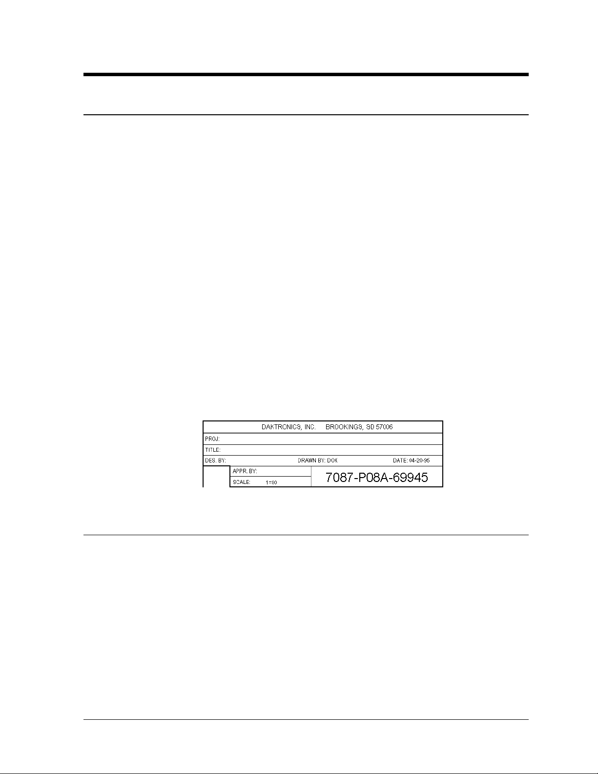
The box below illustrates Daktronics drawing numbering system. The drawing number
Α7087-P08A-69945≅ is how Daktronics identifies individual drawings. This number is
located in the bottom right corner of the drawing. The manual refers to drawings by the last
set of digits and the letter preceding them. In the example, the drawing would be referred to
as Drawing A-69945. All reference drawings are inserted at the end of the first section which
references them.
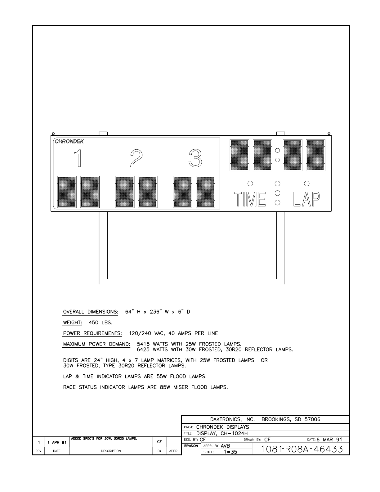
1.2 Display Overview
Reference Drawing: Display, CH-1024H ..................................... Drawing A-46433
Drawing A-46433 shows a Daktronics CH-1024H display. When used with the Daktronics
CHTS-300 timing console, the Daktronics CH-1024H display will show the lap number or lap
time and the first three car positions on the display.
Introduction 1-1
Page 6
Page 7
Section 2: Installation
2.1 General System
Reference Drawings: Driver Enclosure, Power & Signal............... Drawing A-37915
Mounting Instructions.................................. Drawing A-38856
System Layout ............................................ Drawing A-46448
Footing and Beams..................................... Drawing A-46451
Electrical Installation................................... Drawing A-46458
Component Locations................................. Drawing A-46464
Color Code, 25-Pin J-Box ........................... Drawing A-47207
Refer to Drawing A-46448 for the general system layout. The general procedure for
installing the CH-1024H display is as follows:
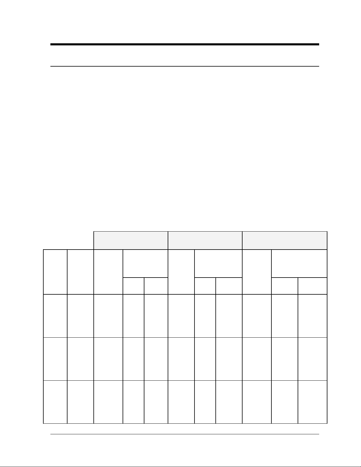
• Select beam and footing recommendations from the table below.
• Dig the footing holes to install beams and footings.
• Route power and signal cables to the display and control locations.
• Mount the displays to the beams as described in Drawings A-38856 and A-46451,
and in Sections 2.2 and 2.3.
• Route power and signal wires into the displays as described in Drawings A-37915, A-
46458, A-46464, and A-47207, and in Section 2.4.
BEAM AND FOOTING RECOMMENDATIONS
DIST
TO
BTM
SCBD
8
12
16
20
24
28
8
12
16
20
24
28
8
12
16
20
24
28
DSG
WIND
VELOC
(MPH)
80
100
Installation 2-1
SCOREBOARDS
BEAM
REQUIRED
(2 EA)
W6X12
W6x15.5
W6x20
W8x24
W8x28
W8x35
W6x15.5
W6x16
W8x20
9
W8x24
0
W8x28
W8x35
W6x15.5
W8x17
W8x24
W8x28
W8x35
W12x53
FOOTINGS
DIAM
(FT)
3.00
3.25
3.50
4.50
4.50
5.00
3.00
3.50
4.00
4.25
4.25
5.50
3.00
3.50
4.25
4.50
4.75
5.25
DEPTH
(FT)
5.00
5.50
6.50
6.50
7.00
7.50
5.50
6.00
7.00
7.50
8.00
8.00
6.00
6.50
7.50
8.00
8.50
9.00
SCOREBOARDS W/
42" ADV PANEL
BEAM
REQUIRED
(2 EA)
W8x15
W8x24
W8x28
W8x35
W8x35
W12x53
W8x17
W8x28
W8x35
W12x36
W12x40
W12x53
W8x24
W8x35
W12x31
W12x36
W12x40
W12x53
FOOTINGS
DIAM
(FT)
3.25
4.50
5.00
5.00
5.25
6.00
4.00
5.50
5.50
5.00
6.00
6.00
5.00
5.25
5.25
6.00
6.00
6.00
DEPTH
(FT)
6.00
7.00
7.50
8.00
8.50
9.00
6.50
7.00
8.00
9.00
9.00
10.00
6.50
8.00
9.00
9.25
10.00
11.00
SCBD W/ 42" ADV
PANEL & MESSAGE BRD
BEAM
REQUIRED
(2 EA)
W8x17
W12x22
W12x27
W12x36
W12x45
W12x50
W8x20
W12x27
W12x31
W12x36
W12x45
W12x50
W12x19
W12x27
W12x36
W12x45
W12x50
W12x58
FOOTINGS
DIAM
(FT)
4.50
5.25
5.25
5.50
6.00
6.00
4.75
6.00
6.00
6.25
6.25
6.25
5.00
6.50
6.50
6.00
6.00
6.00
DEPTH
(FT)
6.00
7.00
8.00
8.50
9.00
10.00
6.50
7.50
8.50
9.00
10.00
11.00
7.00
8.00
9.00
10.00
11.00
12.00
Page 8

These footing recommendations are based on an allowable soil bearing pressure of 300 psf
vertically and 300 psf/ft of depth horizontally. However, these recommendations are
suggestions only and each installation should be treated individually. Be sure that the
installation complies with local codes and is suitable for particular soil and wind conditions.
Daktronics assumes no responsibility for structures installed by others.
A note about beam nomenclature: For a typical beam, W6x16 for example, "W" stands for
"Wide-Flange Beam". The first number (6) is the approximate front to rear dimension of the
beam in inches. The second number (16) is the weight per foot in pounds. This numbering is
a standard in the steal industry. Widths are from 4.00 to 10.00 inches in the chart above.
2.2 Beam And Footing Selection
Reference Drawing: Footing and Beams......................................Drawing A-46451
The above contains recommendations for beams and footings. The distance in the first
column is from the ground to the bottom of the CH-1024H display, regardless if one or two
extra sections, such as an ad panel and/or message center, are added to the CH-1024H scoring
display. The second column is wind velocities that are likely to occur at the display location
in miles per hour.
The beams listed are W-section (wide flange) beams which provide maximum wind load
strength for the weight and cost of the beams. Decide how high you want your display and
what sort of wind it will be subject to. Read across the table to the appropriate column for
your display; these are the beams and footings that are recommended. Drawing A-46451
shows a typical installation of beams and footings.
The calculations for footing diameters and depths are based on the assumption that footings
are in undisturbed soils, not fill soils, with a lateral bearing capacity of 300 psf/ft of depth
horizontally. However, these recommendations are suggestions only and each installation
must comply with local codes and be suitable for the particular soil and wind conditions.
Daktronics recommends that W-section grade 36 steel be used for beam, and that 28-day
(strength 3000 psi) concrete be used for footings. Daktronics assumes no responsibility for
structures installed by others.
2.3 Display Mounting
Reference Drawing: Mounting Instructions...................................Drawing A-38856
Drawing A-38856 shows the typical mounting for your display.
Note: The bolts that secure the display sections do not go through the beams, but run along
the sides of the beam, clamping the display to the beams.
A mounting kit with mounting angles and 2" hardware are provided to mount your display.
Position the display against the mounting beams and secure the bottom of the display to both
beams as shown. Next, secure the top of the display. Once mounting angles are attached, the
display may be slid up or down to the desired height. Once positioned as desired, tighten all
bolts.
2-2 Installation
Page 9

2.4 Electrical Installation
2.4.1 Control Signal Cable
Reference Drawings: Driver Enclosure, Power & Signal... Drawing A-37915
Component Locations ..................... Drawing A-46464
Color Code, 25-Pin J-Box................ Drawing A-47207
For the display, two conductors of 24 AWG are needed. For distances up to 600 ft. or
22 AWG, up to 1000 ft. are required. Daktronics has 24 AWG direct burial cable,
Daktronics part no. W-1105 with 6 conductors, and 22 AWG cable that must be
pulled through the conduit before burial, Daktronics part no. W-1077 with 2
conductors.
At the control location, mount the signal J-box to a convenient location. Route the
cables and connect them to the wires leading from the connector in the cover,
according to the table below and Drawing A-47207.
At the display, open the hinged access door covering the lamp driver enclosure as
shown in Drawing A-46464. Remove the cover from the lamp driver enclosure. See
Drawing A-37915 for an illustration of the components inside the enclosure.
Connect the signal wires to TB31 as indicated in the table below.
Signal Connections
2.4.2 Power Wiring
Installation 2-3
Control End
J-Box
Terminal no.
14 Red/Wht
15 Grn/Wht
*Auxiliary display(s) require(s) a different output number(s). Consult your CHTS300 console manual.
Reference Drawings: Driver Enclosure, Power & Signal... Drawing A-37915
A 120/240 VAC circuit (two hot lines, one neutral, plus a ground) must be run into a
load center. See Drawing A-46458. When equipped with 30W lamps, this display is
capable of drawing a maximum of 40 amps on line 1 and 14 amps on line 2 when
lighted.
Route four "hot", two "neutral", and one "ground" wire, 12 AWG from the load center
(Drawing A-46458) to the driver enclosure (Drawing A-37915) in the display.
Connect the ground wire to terminal E41. Connect the two neutral wires to TB41-3
and TB41-4. Connect the hot wires to the load center and the display as in the
example below.
Wire Color
Electrical Installation ....................... Drawing A-46458
Output
No.
1*
Display End
TB31
Terminal no.
1 (+)
2 (-)
Page 10

Note: Breaker numbers are examples only. Breaker numbers may be assigned as
required. The objective is to have TB41-1 and TB41-2 on line 1. TB41-5 and TB416 should be on line 2.
Load Center
Breaker No.
1
2
3
4
Display Terminal
No.
TB41-1
TB41-2
TB41-5
TB41-6
2-4 Installation
Page 11

Page 12

Page 13

Page 14

Page 15

Page 16

Page 17

Page 18

Page 19

Section 3: Maintenance & Troubleshooting
IMPORTANT NOTES:
1. Disconnect power before any repair or maintenance work is done on
the CH-1024H display!
2. Any access to internal display electronics must be made by qualified
service personnel.
3. Disconnect power when the CH-1024H display is not in use.
3.1 Lamp Replacement
Reference Drawing: Digit Service..............................................Drawing A-27674
The primary service required by the CH-1024H display is to replace burned-out lamps. See
Drawing A-27674 for how to access the digit lamps for replacement. Standard replacement
lamps for the digits are 120V, 25W frosted medium base and may be obtained at your local
store or directly from Daktronics, part number DS-1029. Some displays may be equipped
with 120V, 30W reflector type 30R20 lamps, Daktronics part number DS-1126.
The Lap/Time indicators use 120V, 55W clear flood lamps, type 55PAR38, Daktronics part
number DS-1101.
The Status indicators use 120V, 85W flood lamps, type 85PAR38. The Daktronics part
numbers are as follows:
• Amber - Daktronics Part No. DS-1184
• Green - Daktronics Part No. DS-1185
• Red - Daktronics Part No. DS-1186
Do not use lamps larger than those originally installed in the display. Using higher powered
lamps will likely cause fuse failures in the display and could exceed the current levels that the
display's circuits can safely handle.
3.2 Lamp Drivers
Reference Drawing: Multiplex Controllers..................................Drawing A-37070
Component Location.................................Drawing A-46464
In the scoreboard, the task of switching lamps on and off is performed by the lamp drivers.
Drawing A-46464 in Section 2 shows the location of the lamp driver in the display.
Drawing A-37070 shows the lamp driver and the fuses located in it.
The lamp driver has 22 connectors providing power and signal inputs to the circuit and
outputs to the digits.
Maintenance & 3-1
Troubleshooting
Page 20

Connector No. Function
1-16 Output to digits
17 Signal input
18 Power input for outputs 1-8
19 Power input (120V) for driver logic
20 Power input for outputs 9-16 (120V)
24 Dim option selector
Drawing A-46464 in Section 2 shows the numbers on the digits that refer to the lamp driver
output connector wired to each digit
3.3 Digit Segmentation
Reference Drawing: Segments, 4x7 Lamp Matrix Digit.............Drawing A-37685
In a digit, certain lamps always go on and off together. These groupings of lamps are known
as segments. Each digit can have up to eight segments, referred to by letters A through H.
Drawing A-37685 shows which connector pin number is wired to each digit segment and the
wiring color code used throughout the display.
3.4 Schematic
Reference Drawing: Schematic, Power & Signal.......................Drawing A-38788
Driver Enclosure, Power & Signal.............Drawing A-37915
Drawing A-38788 shows the power and signal inputs into the display and to the lamp driver.
The component numbers correspond to those shown in Drawing A-37915 in Section 2.
3.5 Troubleshooting
This section lists some symptoms that may be encountered with the scoreboard. For these
symptoms, possible cause and corrective actions are indicated. This list does not include
every possible problem, but does represent some of the more common situations that may
occur.
Symptom/Condition Possible Cause or Corrective Action
One lamp won’t light • Burned-out lamp
Scoreboard will not light. • Console not connected or poor connection.
• No power to the control console.
• No power to the scoreboard.
• Bad relay or poor relay connection in signal
circuit.
• Driver logic fuse (F17) blown.
• P17, P19 or P20 unplugged.
Half of the scoreboard will not light. • Circuit breaker tripped at service panel.
• Driver malfunction.
• Poor signal contact at main power connection.
• Driver logic fuse blown
Garbled display. • Control console malfunction.
3-2
Maintenance & Troubleshooting
Page 21

• Internal lamp driver malfunction.
Digit will not light. • Fuse blown in driver.
• Black wire to the digit is broken.
• Poor contact at driver connector.
Segment will not light. • Lamps are burned out.
• Driver malfunction (bad triac).
• Broken wire between lamp driver and digit.
• Poor contact at driver connector.
Segment stays lit. • Driver malfunction (bad triac).
• Broken wire behind digit
If a problem is observed in one digit, the cause may be isolated by swapping plugs on the
driver (connect the plug from the digit into a different jack). If the same digit shows the same
problem, the cause may be in the digit or the wiring. If the problem moves to another digit,
then the cause is probably an internal driver problem.
Use a volt meter at driver inputs to determine if power is being supplied to the driver. An
ohmmeter can be helpful in finding broken wires and bad connections. Internal electronic
problems must be corrected by Daktronics or by an authorized service center.
3.6 Replacement Parts
Part Name or Description Type
Lamp Driver
J-Box, CHTS-300 Timer
Fuse, Lamp Driver, 10A
Fuse, Driver Logic, 1/2A
Digit Lampbank, 24"4x7
S-1064-02
Socket, Med. Base
X-1046
Lamp, 25W Frosted
DS-1029
Lamp, 30W Reflector
Lamp, 55W Clear Flood
Lamp, 85W Amber Flood
Lamp, 85W Green Flood
Lamp, 85W Red Flood
AGC-10
AGC-1/2 F-1000
30R20
55PAR38 DS-1101
85PAR38 DS-1184
85PAR38 DS-1185
85PAR38 DS-1186
Part Number
0A-1033-0122
0A-1067-0056
F-1006
DS-1126
3.7 Daktronics Exchange/Repair & Return Programs
To serve customers’ repair and maintenance needs, Daktronics offers both an exchange and a
repair and return program. The exchange program reduces down time by providing timely
replacement of key components. This service is provided to qualified customers who follow
the program guidelines explained below. It is our pleasure to provide this service to ensure
you get the most from your Daktronics products. Please call our Help Desk (1-800 / 843-
9879) if you have any questions regarding the exchange program or any other Daktronics
service.
Maintenance & 3-3
Troubleshooting
Page 22

When you call the Daktronics Help Desk, a trained service technician will work with you to
solve the equipment problem. You will work together to diagnose the problem and determine
which exchange replacement part to ship. If, after you make the exchange, the equipment still
causes problems, please contact our Help Desk immediately.
If the replacement part fixes the problem, package the defective part in the same packaging the
replacement part arrived in, fill out and attach the enclosed UPS shipping document and
RETURN THE PART TO DAKTRONICS. (You may use the same box and packing the
exchange part was sent in.) This will speed up the transaction and alleviate confusion when
the failed component arrives at Daktronics. (Daktronics expects immediate return of the
exchange part if it does not solve the problem.) For most equipment, you will be invoiced for
the replacement part at the time it is shipped. This invoice is due when you receive it.
Daktronics reserves the right to refuse equipment that has been damaged due to acts of nature
or causes other than normal wear and tear.
If the defective equipment is not shipped to Daktronics within 30 working days from the
invoice date, it is assumed you are purchasing the replacement part and you will be invoiced
for it. This second invoice represents the difference between the exchange price and the
purchase price of the equipment. This amount is due when you receive the second invoice. If
you return the exchange equipment after 30 working days from invoice date, you will be
credited for the amount on the second invoice minus a restocking fee.
≅To avoid a restocking charge, please return the defective equipment within 30 days from the
invoice date.
Daktronics also offers a Repair and Return program for items not subject to exchange.
Where to Send: To return parts for service, contact your local representative prior to
shipment to acquire a Return Material Authorization Number (RMA#). If you have no local
representative, call the Daktronics Help Desk for the RMA#. This will expedite the receiving
process.
Packaging for Return: Package and pad the item well so that it will not be damaged in
shipment. Electronic components such as printed circuit boards should either be installed in an
enclosure or should be put in an anti-static bag before boxing. Please enclose your name,
address, phone number and a clear description of symptoms.
Mail: Daktronics, Inc., Customer Service
PO Box 5128
331 32nd Avenue
Brookings, SD 57006
Phone: Daktronics Help Desk: 1-800/843-9879
or 1-605/697-4400
Customer Service Fax: 1-605-697-4444
e-mail: helpdesk@daktronics.com
3-4
Maintenance &
Troubleshooting
Page 23

Page 24

Page 25

Page 26

 Loading...