

Page 1
Auto Racing Display
Model CH-1018H
Installation & Service Manual
ED 6581
ED 6581
Project# 1081
Rev. 3 - 06 August, 1998
Copyright © 1991 Daktronics, Inc.
All rights reserved. While every precaution
has been taken in the preparation of this
manual, the publisher assumes no
responsibility for errors or omissions. No part
of this book covered by the copyrights
hereon may be reproduced or copied in any
form or by any means - graphic, electronic,
or mechanical, including photocopying,
taping, or information storage and retrieval
systems - without written permission of the
publisher.
DA
KTRONICS, INC.
Setting New Standards Worldwide
Page 2

P.O. Box 5128 331 32nd Ave. Brookings, SD 57006
Phone (605)697-4400 or (800) 843-9879 Fax 697-4444
Page 3

Table of Contents
1. Introduction .............................................................................................................1-1
1.1 How to Use this Manual.............................................................................................1-1
1.2 Display Overview.......................................................................................................1-1
2. Mechanical/Electrical Installation..........................................................................2-1
2.1 General System...........................................................................................................2-1
2.2 Beam and Footing Selection.......................................................................................2-1
2.3 Display Mounting.......................................................................................................2-2
2.4 Electrical Installation..................................................................................................2-2
2.4.1 Control Signal Cable.....................................................................................2-2
2.4.2 Power Wiring ................................................................................................2-3
3. Maintenance & Troubleshooting............................................................................3-1
3.1 Lamp Replacement.....................................................................................................3-1
3.2 Lamp Driver...............................................................................................................3-1
3.3 Digit Segmentation.....................................................................................................3-2
3.4 Schematic ...................................................................................................................3-2
3.5 Troubleshooting .........................................................................................................3-2
3.6 Replacement Parts......................................................................................................3-3
3.7 Unit Exchange/Replacement Procedure.....................................................................3-3
Table of Contents
i
Page 4

Page 5
Section 1: Introduction
1.1 How to Use this Manual
This manual explains the installation and maintenance of the Daktronics CH-1018H auto
racing display system. Setup of other control equipment or operation of the CHTS-300 timing
console are not covered in this manual. For questions regarding the safety, installation,
operation or service of this system, please refer to the telephone numbers listed on the cover
page of this manual.
Important Safeguards:
1. Read and understand these instructions before installing.
2. Do not drop the control console or allow it to get wet.
3. Be sure the display is properly grounded with a ground rod at the display location.
4. Disconnect power to the display when it is not in use.
5. Disconnect power when servicing the display.
6. Do not modify the display structure or attach any panels or coverings to the
display without the written consent of Daktronics, Inc.
The box below illustrates Daktronics drawing numbering system. The drawing number
“7087-P08A-69945” is how Daktronics identifies individual drawings. This number is
located in the lower-right corner of the drawing. This manual refers to drawings by listing the
last set of digits and the letter preceding them. In the example below, the drawing would be
referred to as Drawing A-69945. Referenced drawings are inserted at the end of the first
section which references them.
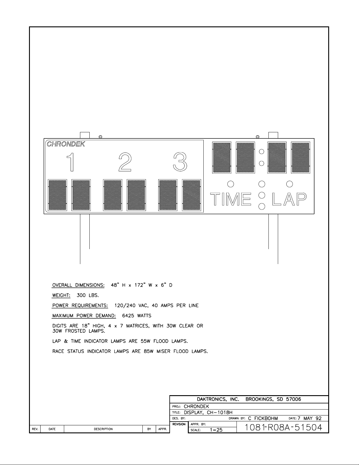
1.2 Display Overview
Reference Drawing: Display, CH-1018H......................................Drawing A-51504
Drawing A-51504 shows a Daktronics CH-1018H display. The CH-1018H display along
with the use of the Daktronics CHTS-300 timing console will display the lap number and lap
time on the display.
Introduction 1-1
Page 6
Page 7
Section 2: Mechanical/Electrical Installation
2.1 General System
Reference Drawings: Driver Enclosure, Power & Signal ...............Drawing A-37915
Mounting Instructions..................................Drawing A-38856
Color Code, 25-Pin J-Box ...........................Drawing A-47207
System Layout, CH-1018H .........................Drawing A-51505
Component Locations, CH-1018H..............Drawing A-51511
Electrical Installation, CH-1018H................Drawing A-51519
Footing & Beams, CH-1018H......................Drawing A-51520
Refer to Drawing A-51505 for a general system layout.
The general procedure for installing the CH-1018H display is as follows:
1. Select beam and footing recommendations from the table below.
2. Dig the footing holes and install beams and footings.
3. Route power and signal cables to the display and control locations.
4. Mount the displays to the beams as described in Section 2.3 and Drawings A-38856 and
A-51520.
5. Route power and signal wires into the displays as described in Section 2.4 and Drawings
A-37915, A-47207, A-51511, and A-51519.
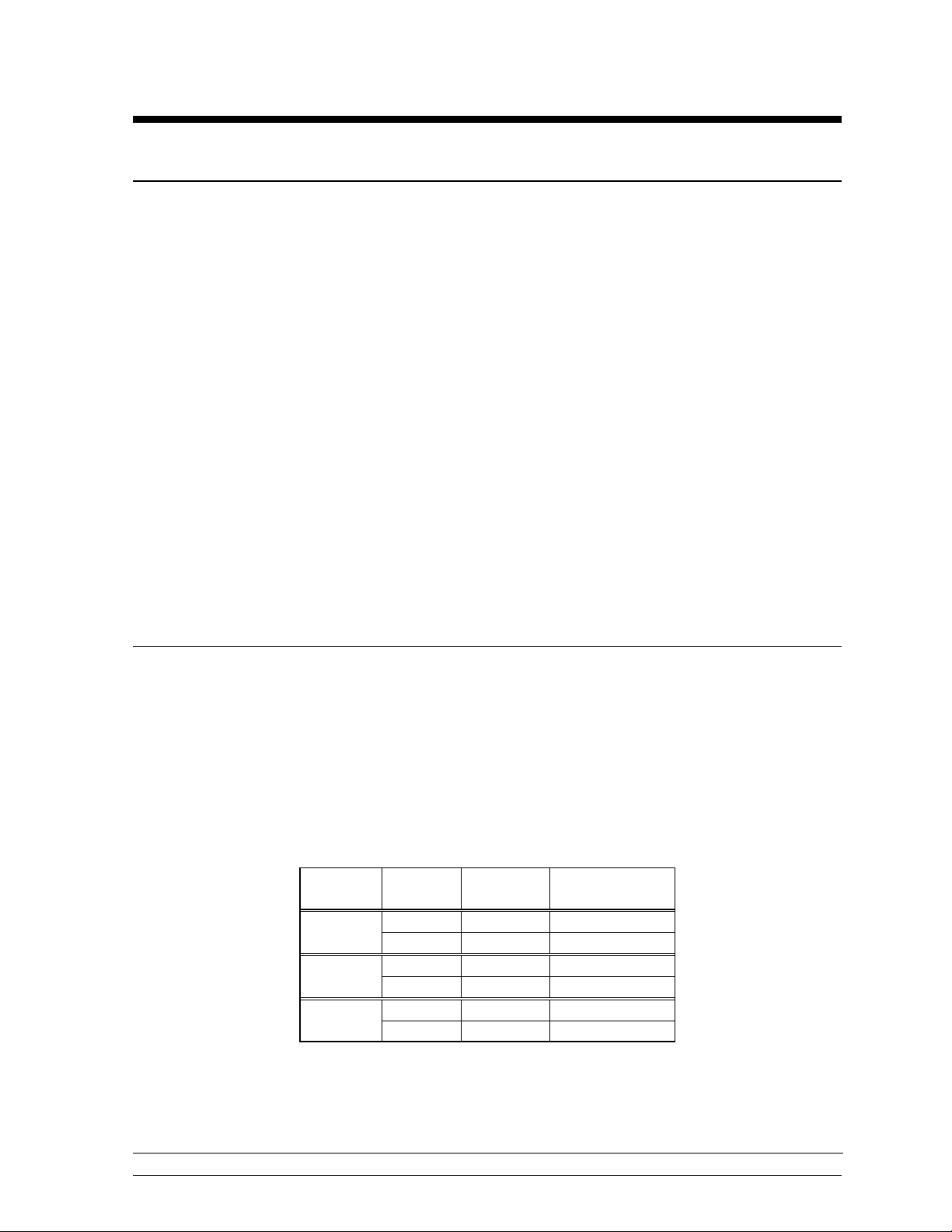
2.2 Beam and Footing Selection
Reference Drawing: Footing and Beams, CH-1018H ....................Drawing A-51520
The table below contains recommendations for W-shape beams and footings to support the
display as shown in Drawing A-51520. The first column is wind velocity in miles per hour.
The distance in the second column is from the ground to the bottom of the display. The
choice from these columns depends upon the display location.
The beams listed below are beams which provide maximum wind load strength for the weight
and cost of the beams.
Wind
Speed
70 mph 10 W8 x 15 4 ¾ ft x 3 ft
15 W6 x 20 5 ½ ft x 3 ft
80 mph 10 W8 x 15 5 ½ ft x 3 ft
15 W8 x 20 6 ¾ ft x 3 ft
90 mph 10 W8 x 17 6 ¼ ft x 3 ft
15 W8 x 24 7 ft x 3 ft
The calculations for footing diameters and depths are based on the assumption that footings
are in undisturbed soils, not fill soils. Lateral bearing capacity of 300 psf per foot of depth in
natural grade was used to derive these figures.
Height
(ft)
Beam
Section
Footing
Depth x Dia.
Installation
2-1
Page 8

The footing recommendations are based on the allowable soil bearing pressure of 3000 psf
vertically and 300 psf/ft of depth horizontally. However, these recommendations are
suggestions only and soil bearing pressure at the site must be determined by a sample test prior
to specifying actual footings. Be sure that the installation complies with local codes and is
suitable for the particular soil and wind conditions. Daktronics assumes no responsibility for
structures installed by others. Daktronics recommends that W-sections of grade 35 steel be used
for beams, and that 28-day (strength 3000 psi) concrete be used for footings.
A note about beam nomenclature: For a typical beam, W6 x 12 for example "W" stands for
"Wide-Flange Beam". The first number (6) is the approximate front to rear dimension of the
beam in inches. The second number (12) is the weight per foot in pounds. This numbering is a
standard in the steel industry. Widths are from 6.00 to 8.00 inches in the chart above.
2.3 Display Mounting
Reference Drawing: Mounting Instructions ....................................Drawing A-38856
Drawing A-38856 shows the typical mounting for the display.
Note: The bolts that secure the display sections do not go through the beams, but run along
both sides of the beam to clamp the display to the beams.
A mounting kit consisting of mounting angles and 1/2" hardware are provided to mount the
display.
Position the display against the mounting beams and secure the bottom of the display to both
beams as shown. Next, secure the top of the display. Once mounting angles are attached, the
display may be slid up or down to the desired height. Once positioned as desired, tighten all
bolts.
2.4 Electrical Installation
2.4.1 Control Signal Cable
Reference Drawings: Driver Enclosure, Power & Signal....Drawing A-37915
For the display, two conductors of 24 AWG are needed. For distances up to 600 ft. or
22 AWG, up to 1000 ft. are required. Daktronics has 24 AWG direct burial cable,
Daktronics part no. W-1105 with 6 conductors, and 22 AWG cable that must be
pulled through the conduit before burial, Daktronics part no. W-1077 with 2
conductors.
At the control location, mount the signal J-box to a convenient location. Route the
cables and connect to the wires leading from the connector in the cover according to
the table below and Drawing A-47207.
At the display, open the bottom hinged panel covering the entrance enclosure as
shown on Drawing A-51511. Remove the cover from the entrance enclosure. Refer
Color Code, 25-Pin J-Box ...............Drawing A-47207
Component Locations,CH-1018H...Drawing A-51511
2-2
Installation
Page 9

to Drawing A-37915 for an illustration of the components inside the entrance
enclosure. Connect the signal wires to TB31 as indicated in the table below.
Control End Display End
J-box Terminal No. Wire Color Output No. TB31 Terminal No.
14 Red/Wht 1* 1 (+)
15 Grn/Wht 2 (-)
*Auxiliary display(s) require(s) a different output no.(s). Consult your CHTS-300 console
manual.
2.4.2 Power Wiring
Reference Drawing: Driver Enclosure, Power & Signal.......Drawing A-37915
Electrical Installation ..........................Drawing A-51519
A 120/240 VAC circuit (two hot lines, one neutral, plus a ground) must be run into a
load center. Refer to Drawing A-51519. With all lamps lighted, this display is
capable of drawing a maximum of 40 amps on one line and 14 amps on the other line.
Route four "hot", two "neutral", and one "ground" wire of 12 AWG from the load
center (Drawing A-51519) to the driver enclosure (Drawing A-37915) in the display.
Refer to Drawing A-37915 for component locations at the driver. Connect the
ground wire to terminal E41. Connect the two neutral wires to TB41-3 and TB41-4.
Connect the hot wires to the load center and display as in the example below.
Load Center Breaker No. Display Terminal No.
1 TB41-1
2 TB41-2
3 TB41-5
4 TB41-6
Note: Breaker numbers are examples only. Breaker numbers may be assigned as
required. The objective is to have TB41-1 & TB41-2 on line 1. TB41-5 & TB41-6
should be on line 2.
Installation
2-3
Page 10

Page 11

Page 12

Page 13

Page 14

Page 15

Page 16

Page 17

Page 18

Page 19
Section 3: Maintenance & Troubleshooting
IMPORTANT NOTES:
1. Disconnect power before any repair or maintenance work is done on the
display!
2. Any access to internal display electronics must be made by qualified
service personnel.
3. Disconnect power when the display is not in use.
3.1 Lamp Replacement
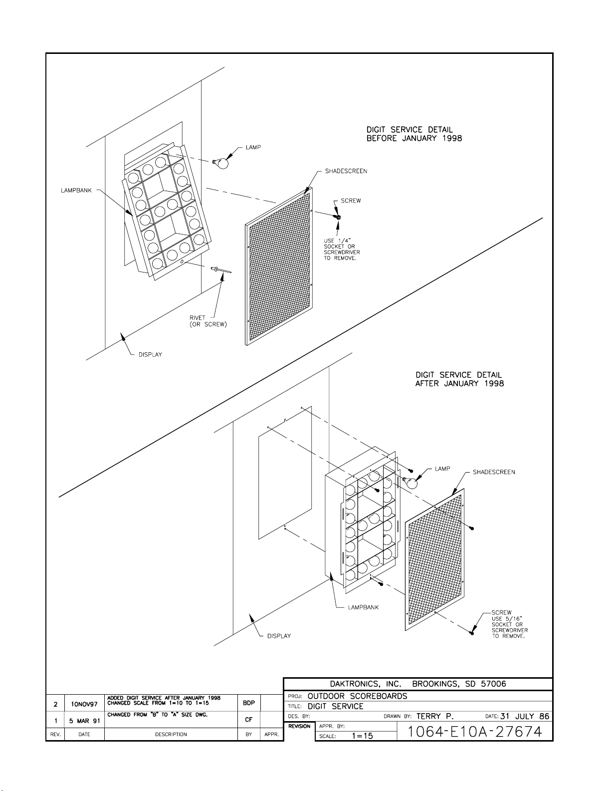
Reference Drawing: Digit Service ..................................................Drawing A-27674
The primary service required by the CH-1018H display is to replace burned-out lamps. Refer
to Drawing A-27674 for an illustration of how to access the digit lamps for replacement.
Standard replacement lamps for the digits are 120V, 30W frosted medium base and may be
obtained at your local store or directly from Daktronics, part number DS-1182. Some displays
may be equipped with 120V, 30W clear lamps, Daktronics part number DS-1076.
The Lap/Time indicators use 120V, 55W clear flood lamps, type 55PAR38, Daktronics part
number DS-1101.
The Status indicators use 120V, 85W flood lamps, type 85PAR38. The Daktronics part
numbers are as follows:
Color Part Number
Amber DS-1184
Green DS-1185
Red DS-1186
Do not use lamps larger than those originally installed in the display. Using higher powered
lamps will likely cause fuse failures in the display and could exceed the current levels that the
display's circuits can safely handle.
3.2 Lamp Driver
Reference Drawings: Lamp Driver, 16 Col., w/ Fan.......................Drawing A-37070
Component Locations,CH-1018H................DrawingA-51511
In the display, the task of switching lamps on and off is performed by the lamp driver.
Drawing A-51511 in Section 2 shows the location of the lamp driver in the display.
Drawing A-37070 is an illustration of the lamp driver and the fuses located in it.
Maintenance & Troubleshooting
3-1
Page 20

The lamp driver has 22 connectors, providing power and signal inputs and outputs to digits.
The functions of these connectors are as follows:
Connector Number Function
1-16 Outputs to digits
17 Signal Input
18 Power input for outputs 1-8 (120 V)
19 Power input for driver logic and fan (120V)
20 Power input for outputs 9-16 (120V)
24 Dim option selector
In Drawing A-51511, the numbers on the digits refer to the lamp driver output connector
wired to each digit.
3.3 Digit Segmentation
Reference Drawing: Segments, 4x7 Lamp Matrix Digit..................Drawing A-37685
In a digit certain lamps always go on and off together. These groupings of lamps are known
as "segments". Each digit has eight segments, referred to by letters A through H. Drawing
A-37685 illustrates these segments and shows which connector pin and wire color is wired to
each segment.
3.4 Schematic
Reference Drawings: Driver Enclosure, Power & Signal ...............Drawing A-37915
The schematic diagram in Drawing A-38788 shows the power and signal inputs into the
display and to the lamp driver. The component numbers correspond to those shown in
Drawing A-37915 in Section 2.
3.5 Troubleshooting
This section lists some symptoms that may be encountered with the CH-1018H display. For
these symptoms, possible causes and corrective actions are indicated. This list does not
include every possible problem, but does represent some of the more common situations that
may occur.
Observed Problem Possible Cause
One lamp won’t light
Digit segment won’t light
Entire digit won’t light
Half the display won’t light
Schematic, Pwr & Sig, CH-21GP................Drawing A-38788
• Burned-out lamp
• Broken wire behind digit
• Broken wire
• Poor contact at driver connector
• Internal driver malfunction
• Broken wire (black)
• Poor contact at connector, pin 7
• Fuse blown in driver
• Service breaker tripped
3-2
Maintenance & Troubleshooting
Page 21

• Main fuse blown
• Poor contact at main power connection
• P18 disconnected
Entire display won’t light
• Power disruptions
• Poor signal connection
• Driver logic fuse blown
• Control not connected to display
• P20 disconnected
Segment stays lit
• Broken wire behind digit
• Internal driver malfunction
Garbled display
• Control malfunction
• Internal driver malfunction
If a problem is observed in one digit, the cause may be isolated by swapping plugs on the
driver (connect the plug from the digit into a different jack). If the same digit shows the same
problem, the cause may be in the digit or the wiring. If the problem moves to another digit,
then the cause is probably an internal driver problem.
Use a volt meter at driver inputs to determine if power is being supplied to the driver. An
ohmmeter can be helpful in finding broken wires and bad connections. Internal electronic
problems must be correct by Daktronics or an authorized service center.
3.6 Replacement Parts
Part Name or Description Type Part Number
Lamp Driver 0A-1033-0122
J-Box, CHTS-300 Timer 0A-1067-0056
Fuse, Lamp Driver, 10A AGC-10 F-1006
Fuse, Driver Logic, 1/2A AGC-1/2 F-1000
Digit Lampbank, 18” 4x7 0A-1027-0071
Digit Screen, 18” 4x7 0S-1064-0001
Socket, Med. Base X-1046
Lamp, 30W Frosted DS-1182
Lamp, 30W Clear 30A15 DS-1076
Lamp, 55W Clear Flood 55PAR38 DS-1101
Lamp, 85W Amber Flood 85PAR38 DS-1184
Lamp, 85W Green Flood 85PAR38 DS-1185
Lamp, 85W Red Flood 85PAR38 DS-1186
3.7 Unit Exchange/Replacement Procedure
Daktronics unique exchange program offers our clients the quickest, most economical way of
receiving product repairs. If a component fails, Daktronics will send the customer a
replacement. The customer, in turn, sends the failed component to Daktronics. This not only
saves money but decreases the time the display is inoperable. Daktronics offers repair and
return on a timely basis; in urgent situations, every attempt is made to ship by the fastest
transit method available.
1. Packaging for Return: Package and pad the item well to prevent damage during
shipment. Electronic components, such as printed circuit boards, should either be
Maintenance & Troubleshooting
3-3
Page 22

installed in an enclosure or placed in an anti-static bag before boxing.
Please enclose your name and address along with a list of all the symptoms. Please be
as specific as possible.
2. Driver Packaging Instructions: Drivers should be placed in a static-free enclosure
for return shipping. An anti-static convoluted foam packing is available from
Daktronics (part number PK-1135). The shipping box (Daktronics part number PK-
1006) should be used along with the foam.
3. Where to Send: Contact your local representative prior to shipment to acquire a
Return Material Authorization Number (RMA#). This will speed up the repair of
your unit.
When returning defective items under the exchange program, please use the UPS Blue
Return Tags found in the package containing the exchange unit sent from Daktronics.
This will speed up the transaction and help avoid confusion when the part is returned
to Daktronics. The defective item must be returned within 15 days of receiving a
replacement part. Using the UPS Blue Return Tag immediately will eliminate the
possibility of late charges being assessed against your account.
Mail: Daktronics, Inc., Customer Service
PO Box 5128
331 32
nd
Avenue
Brookings, SD 57006
Phone: Toll Free: 1-800-843-9879
or 1-605-697-4400
Customer Service Fax: 1-605-697-4444
E-Mail: helpdesk@daktronics.com
3-4
Maintenance & Troubleshooting
Page 23
Page 24

Page 25

Page 26

 Loading...