

Page 1
Models
BB-2102
BB-2126
BB-2104
BB-2146
BB-2106
BB-2147
BB-2108
BB-2154
BB-2124
BB-2156
Daktronics Tuff Sport®
Four-Sided Basketball
LED Scoreboards
Display Manual
ED-13248 Rev 6 – 7 February 2013
201 Daktronics Drive PO Box 5128 Brookings, SD 57006-5128
Tel: 1-800-DAKTRONICS (1-800-325-8766) Fax: 605-697-4746
www.daktronics.com
Page 2

Page 3

Please fill in the information below for your display; use it for reference when
calling Daktronics for assistance.
Scoreboard Serial No. __________________________________________
Scoreboard Model No. __________________________________________
Date Installed _________________________________________________
ED-13248
Product 1237
Rev 6 – 7 February 2013
DAKTRONICS, INC.
Copyright 2003-2013
All rights reserved. While every precaution has been taken in the preparation of this manual, the publisher
assumes no responsibility for errors or omissions. No part of this book covered by the copyrights hereon may be
reproduced or copied in any form or by any means – graphic, electronic, or mechanical, including photocopying,
taping, or information storage and retrieval systems – without written permission of the publisher.
All Sport®, PanaView®, Tuff Sport®, and UniView® and are trademarks of Daktronics, Inc.
Page 4

Page 5

Table of Contents
Section 1: Introduction ............................................................................................................................ 1
1.1 Scoreboard Controllers ........................................................................................................... 1
1.2 Scoreboard Label ..................................................................................................................... 2
1.3 Model Number ........................................................................................................................ 2
1.4 Resources .................................................................................................................................. 2
1.5 Daktronics Nomenclature ...................................................................................................... 3
1.6 Product Safety Approval........................................................................................................ 3
Section 2: Specifications .......................................................................................................................... 5
Section 3: Mechanical Installation ........................................................................................................ 7
3.1 Lifting the Scoreboard ............................................................................................................ 7
3.2 Four-Sided Scoreboard Suspension Options ....................................................................... 8
Static Mounting ................................................................................................................ 8
Electric Hoist System ....................................................................................................... 9
3.3 Assembly Overview.............................................................................................................. 10
3.4 Frame Assembly .................................................................................................................... 10
BB-2146 and BB-2147 ..................................................................................................... 10
3.5 Optional Lower Ad Panel Attachment............................................................................... 11
3.6 Mounting Scoreboard Sections to the Frame ..................................................................... 11
BB-2146 and BB-2147 ..................................................................................................... 11
3.7 Optional Top Ad Panel or Message Center Attachment ................................................. 12
3.8 Optional Ad Panels on Message Centers ........................................................................... 12
3.9 Attaching Corner Shrouds ................................................................................................... 13
3.10 Attaching Suspension Cables .............................................................................................. 13
Section 4: Electrical Installation .......................................................................................................... 15
4.1 Installation Overview ........................................................................................................... 15
4.2 Power/Signal Connections Between Sections ................................................................... 16
4.3 Main Power Connection ....................................................................................................... 18
Grounding ....................................................................................................................... 18
4.4 Power-On Self-Test (POST) ................................................................................................. 18
Radio Settings ................................................................................................................. 19
4.5 Main Signal Connection ....................................................................................................... 19
Section 5: Maintenance & Troubleshooting ...................................................................................... 21
5.1 Troubleshooting Table .......................................................................................................... 21
5.2 Component Location & Access ........................................................................................... 23
5.3 Replacing Digits .................................................................................................................... 24
PanaView ........................................................................................................................ 24
UniView .......................................................................................................................... 25
5.4 LED Drivers ........................................................................................................................... 26
Replacing a Driver ......................................................................................................... 28
Setting the Driver Address ........................................................................................... 28
Multiple Drivers ............................................................................................................. 28
5.5 Segmentation and Digit Designation .................................................................................. 29
Table of Contents i
Page 6

5.6 Schematics .............................................................................................................................. 29
5.7 Suspension System Periodic Inspections ........................................................................... 29
Static System ................................................................................................................... 29
Hoist System ................................................................................................................... 29
5.8 Replacement Parts List ......................................................................................................... 30
5.9 Daktronics Exchange and Repair & Return Programs ..................................................... 31
Exchange Program ......................................................................................................... 31
Repair & Return Program ............................................................................................. 32
Daktronics Warranty and Limitation of Liability ...................................................... 32
Section 6: Scoreboard Options ............................................................................................................. 33
6.1 Horns ...................................................................................................................................... 33
Adjusting Horn Volume ................................................................................................ 33
6.2 Radio Control ......................................................................................................................... 33
6.3 Visual Horn Indicator (VHI) ................................................................................................ 33
6.4 Changeable Captions ............................................................................................................ 34
6.5 Double Bonus Indicators ...................................................................................................... 34
6.6 Time Outs Left (TOL) Digits ................................................................................................ 34
6.7 Team Name Message Centers ............................................................................................. 34
Section 7: TNMC Troubleshooting & Maintenance ........................................................................ 35
7.1 Display Overview ................................................................................................................. 35
7.2 Initialization Information at Startup ................................................................................... 36
7.3 Display Troubleshooting Table ........................................................................................... 36
7.4 Power & Signal Summary .................................................................................................... 37
7.5 Component Locations & Access .......................................................................................... 37
7.6 Display Drivers ...................................................................................................................... 37
Diagnostic LEDs ............................................................................................................. 38
Replacing a Driver ......................................................................................................... 38
7.7 Modules .................................................................................................................................. 39
Replacing Modules ........................................................................................................ 39
7.8 Power Supplies ...................................................................................................................... 40
Replacing a Power Supply ............................................................................................ 40
7.9 Display Maintenance ............................................................................................................ 40
7.10 Replacement Parts List ......................................................................................................... 40
Appendix A: Mechanical Specification Drawings ................................................................................. 41
Appendix B: Electrical Specification Drawings ..................................................................................... 43
Appendix C: Scoreboard Options ............................................................................................................. 45
Appendix D: Schematic Drawings ............................................................................................................ 47
Appendix E: Additional Reference Drawings ........................................................................................ 49
Appendix F: Hoist Suspension Systems ................................................................................................. 51
Appendix G: Daktronics Warranty and Limitation of Liability .......................................................... 53
ii Table of Contents
Page 7

1
Section 1: Introduction
This manual explains the installation and maintenance of Daktronics Tuff Sport® Four-Sided Indoor
Basketball LED Scoreboards. For additional information regarding the safety, installation, operation,
or service of these displays, refer to the telephone numbers listed in Section 5.9. This manual is not
specific to a particular installation.
Important Safeguards:
Please read and understand all instructions before beginning the installation process.
Do not drop control equipment or allow it to get wet.
Do not disassemble control equipment or electronic controls of the display; failure to
follow this safeguard will make the warranty null and void.
Disconnect display power when not in use or when servicing.
Disconnect display power before servicing power supplies to avoid electrical shock.
Power supplies run on high voltage and may cause physical injury if touched while
powered.
Do not modify the scoreboard structure or attach any panels or coverings to the
scoreboard without the express written consent of Daktronics, Inc.
Project-specific information takes precedence over any other general information found in
this manual.
1.1 Scoreboard Controllers
Daktronics four-sided Tuff Sport scoreboards are designed for use with the All Sport® 5000
series control consoles. This console uses keyboard overlays (sport inserts) to control numerous
sports and scoreboard models. Refer to the following manual for operating instructions:
All Sport 5000 Series Control Console Operation Manual (ED-11976)
This control console manual is available online at www.daktronics.com/manuals.
Introduction
Page 8
1.2 Scoreboard Label
BB
Basketball
Figure 1: Display ID Label
-13
indoor scoreboards, 120 V, PanaView® digits
-14
indoor scoreboards, 230 V, PanaView® digits
-15
indoor scoreboards, 120 V, UniView® digits
-16
indoor scoreboards, 230 V, UniView® digits
Figure 2: Daktronics Drawing Label
Serial and model numbers of a Daktronics scoreboard can be found on the ID label on the
display, similar to that shown in Figure 1.
Please list the model number, display serial number, and the date this display became
operational in the blanks provided on the second page of this manual. When calling
Daktronics customer service, please have this information available to ensure the request is
serviced as quickly as possible.
1.3 Model Number
Daktronics scoreboards are differentiated by their model numbers and two-letter prefixes for
each sport. Most Daktronics scoreboards also carry a two-number suffix that refers to indooroutdoor status, power supply, and digit color.
1.4 Resources
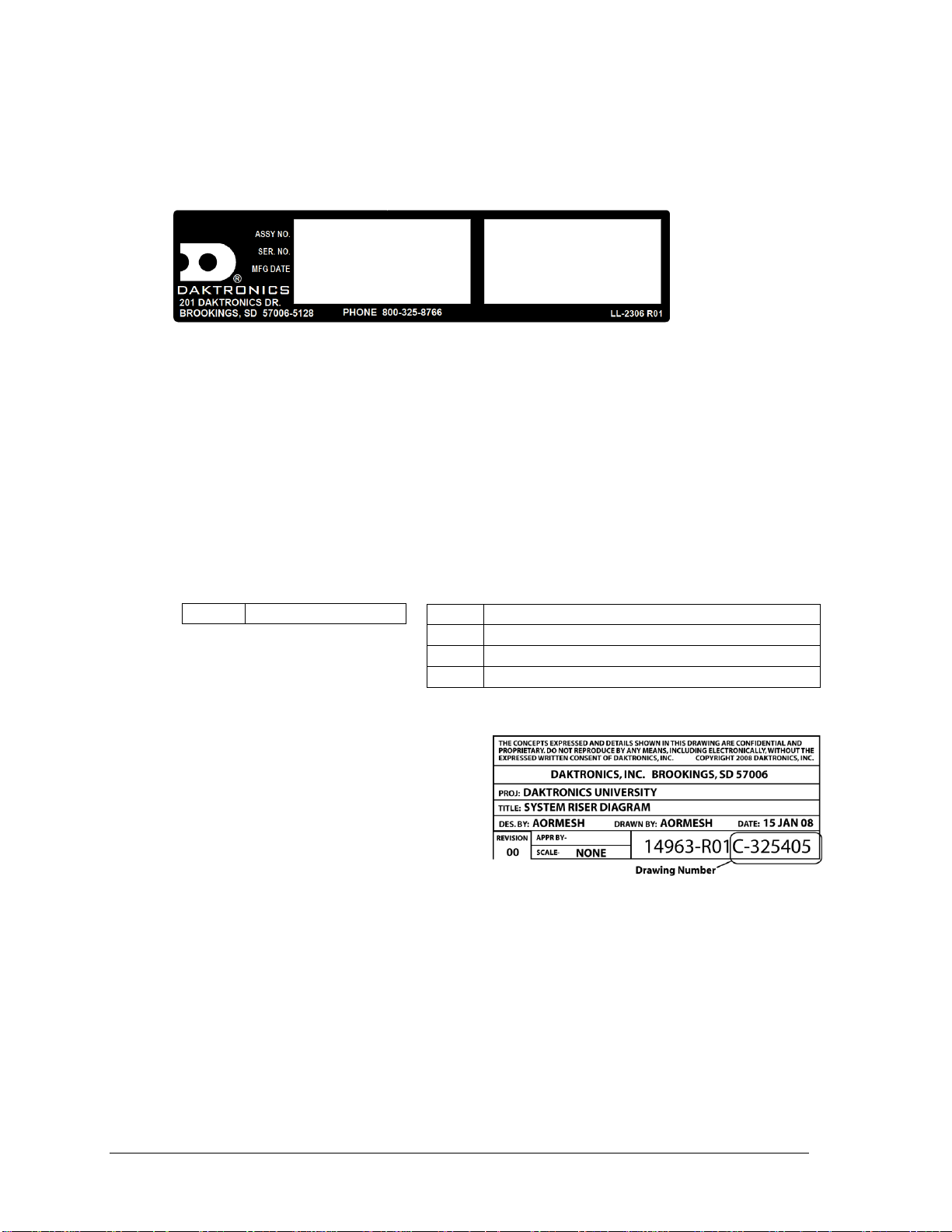
Figure 2 illustrates a Daktronics drawing
label. The drawing number is located in the
lower-right corner of a drawing. This manual
refers to drawings by listing the last set of
digits and the letter preceding them. In the
example, the drawing would be referred to
as Drawing C-325405.
Reference Drawing:
System Riser Diagram ............................................................................Drawing C-325405
Daktronics identifies manuals by the DD or ED number located on the cover page of each
manual. For example, this manual would be referred to as ED-13248.
2 Introduction
Page 9
3
Main Component Labels
Part Type
Part Number
Individual circuit board
0P-XXXX-XXXX
Assembly; a collection of circuit boards
0A-XXXX-XXXX
Wire or cable
W-XXXX
Fuse
F-XXXX
Transformer
T-XXXX
Metal part
M-XXX
Fabricated metal assembly
0S-XXXXXX
Specially ordered part
PR-XXXXX-X
Accessory Labels
Component
Label
Termination block for power
or signal cable
TBXX
Grounding point
EXX
Power or signal jack
JXX
Power or signal plug for the
opposite jack
PXX
Figure 3: Typical Label
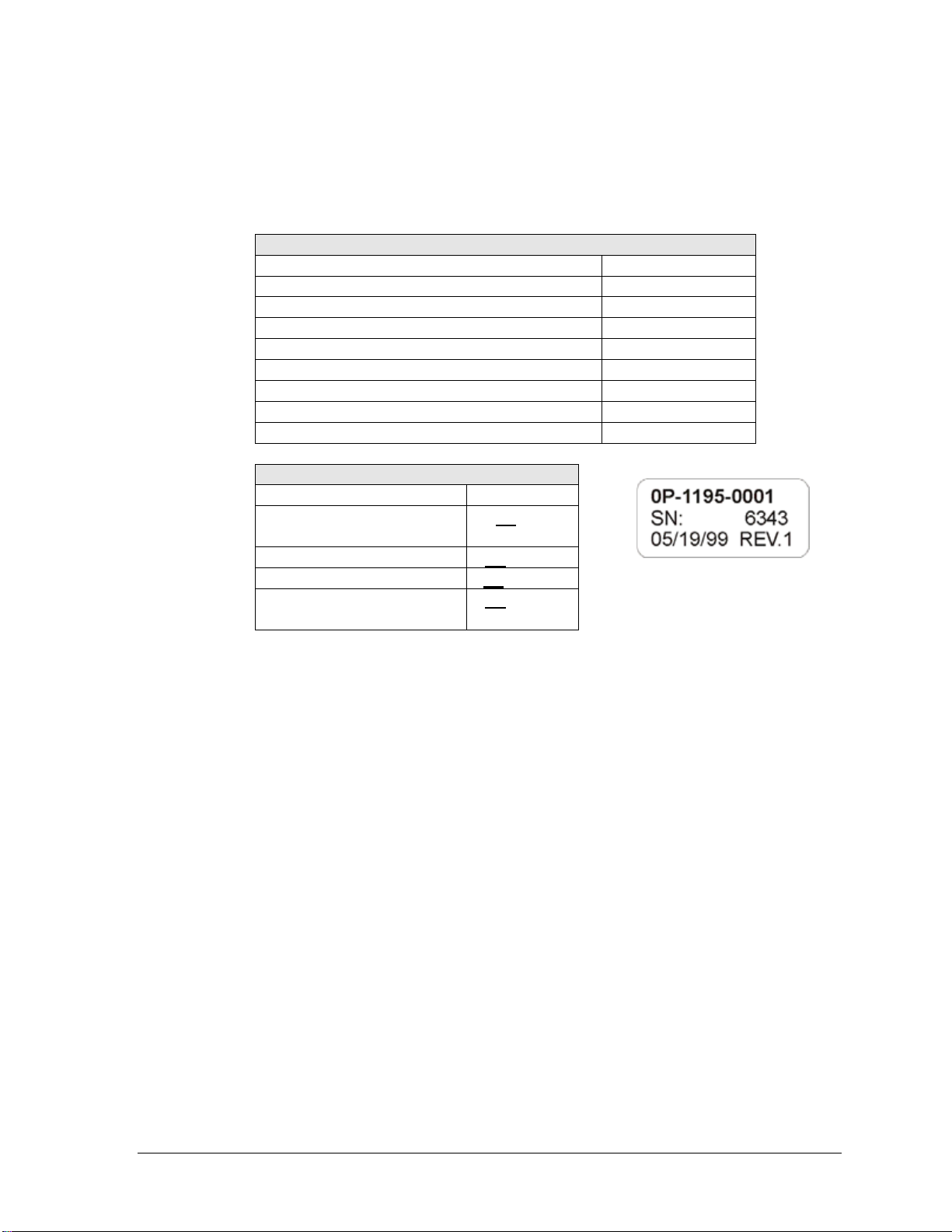
1.5 Daktronics Nomenclature
Most components within this display carry a white label that lists the part number of the unit.
If a component is not found in the Replacement Parts List in Section 5.8, use the label to order
a replacement. Figure 3 illustrates a typical label. The part number is in bold.
Following the Replacement Parts List is the Daktronics Exchange Policy and the Repair &
Return Program. Refer to these instructions if replacing or repairing any display component.
1.6 Product Safety Approval
Daktronics Tuff Sport scoreboards are ETL-listed, tested to CSA standards and CE-labeled for
indoor use. Contact Daktronics with any questions regarding the testing procedures.
Note: The four-sided scoreboards detailed in this manual are designed to be suspended
above players or spectators, and that creates serious liability considerations. It is
imperative that the roof support system be able to bear the weight of the scoreboard and
all other attachments. Consequently, a licensed engineer must certify the roof support
system. Suspension cables and hoist or attachment structures must also be designed and
certified by a licensed engineer.
Daktronics is not responsible for structures and suspension systems designed or installed
by others.
Introduction
Page 10

Page 11
Model
Dimensions:
Height, Width, Depth
Uncrated
Weight
Watts
Amps
120/230 VAC
Driver #
& Address
BB-2102
4'-2" H, 10'-10" W, 10'-10" D
(1270 mm, 3302 mm, 3302 mm)
780 lb
354 kg
[840 lb
381 kg]
800 W
[1200 W]
6.7 / 3.5 A
[10 / 5.2 A]
A1 17
BB-2104
6'-2" H, 10'-10" W, 10'-10" D
(1880 mm, 3302 mm, 3302 mm)
1020 lb
463 kg
[1080 lb
490 kg]
800 W
[1200 W]
6.7 / 3.5 A
[10 / 5.2 A]
A1 17
BB-2106
4'-2" H, 12'-10" W, 12'-10" D
(1270 mm, 3912 mm, 3912 mm)
900 lb
408 kg
[960 lb
435 kg]
800 W
[1200 W]
6.7 / 3.5 A
[10 / 5.2 A]
A1 17
BB-2108
6'-2" H, 12'-10" W, 12'-10" D
(1880 mm, 3912 mm, 3912 mm)
1200 lb
544 kg
[1260 lb
572 kg]
800 W
[1200 W]
6.7 / 3.5 A
[10 / 5.2 A]
A1 17
BB-2124
6'-2" H, 12'-10" W, 12'-10" D
(1880 mm, 3912 mm, 3912 mm)
1220 lb
553 kg
[1280 lb
581 kg]
1600 W
[2000 W]
13.3 / 7 A
[16.7 / 8.7 A]
A1 17
A2 14
BB-2126
4'-2" H, 12'-10" W, 12'-10" D
(1270 mm, 3912 mm, 3912 mm)
900 lb
408 kg
[960 lb
435 kg]
800 W
[1200 W]
6.7 / 3.5 A
[10 / 5.2 A]
A1 17
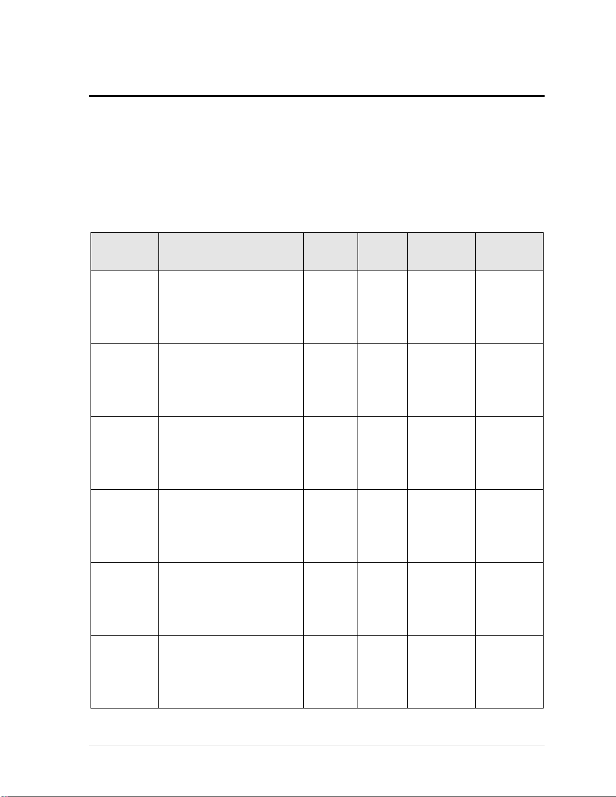
Section 2: Specifications
The chart on the following pages details all of the mechanical specifications, circuit specifications, and
power requirements for each display in this manual. Models are listed in alphanumeric order.
Notes:
1) All displays require a 120 VAC, 15 A circuit; models with 230 VAC power are also available.
2) Values in [Brackets] indicate scoreboards with Team Name Message Centers (TNMC).
3) Dimensions include corner shrouding and flooring.
4) Optional sheet metal flooring adds 100 lb (45 kg) to total weight.
Specifications 5
Page 12
Model
Dimensions:
Height, Width, Depth
Uncrated
Weight
Watts
Amps
120/230 VAC
Driver #
& Address
*BB-2146
8'-8" H, 12'-10" W, 12'-10" D
(2642 mm, 3912 mm, 3912 mm)
2750 lb
1247 kg
[2810 lb
1274 kg]
7488 W
[7888 W]
62.4 / 32.6 A
[65.7 / 34.3 A]
A1 17
*BB-2147
8'-8" H, 12'-10" W, 12'-10" D
(2642 mm, 3912 mm, 3912 mm)
2000 lb
907 kg
[2060 lb
934 kg]
4144 W
[4544 W]
34.5 / 18 A
[38 / 19.8 A]
A1 17
BB-2154
6'-2" H, 10'-10" W, 10'-10" D
(1880 mm, 3302 mm, 3302 mm)
1080 lb
490 kg
[1140 lb
517 kg]
1400 W
[1800 W]
11.7 / 6.1 A
[15 / 7.8 A]
A1 17
BB-2156
6'-2" H, 12'-10" W, 12'-10" D
(1880 mm, 3912 mm, 3912 mm)
1260 lb
572 kg
[1320 lb
599 kg]
1400 W
[1800 W]
11.7 / 6.1 A
[15 / 7.8 A]
A1 17
* These displays are composed of scoreboards and LED message centers. Refer to the SS Series 20mm
Indoor Scoreboard Message Centers Installation & Operation Manual (DD1564453) for more
information about message center specifications, operation, and troubleshooting.
6 Specifications
Page 13

Section 3: Mechanical Installation
Mechanical installation consists of lifting and permanently mounting the scoreboard and any optional
advertising panels or message centers. The mechanical specification drawings listed in Appendix A
show measurements, cable attachment points, and mounting weights for each scoreboard model.
Be sure that the installation complies with local building codes.
Note: Daktronics does not assume any liability for any installation derived from the information
provided in this manual or installations designed and installed by others.
Below is a general overview of the entire installation process. Each step is detailed in the sections that
follow, and the instructions are presented in the general order in which events should occur.
1. Plan and install the hoist or static-suspension structure.
2. Provide power circuit(s) and outlet(s) at the scoreboard location.
3. Provide a power outlet at the control location.
4. Route signal cable from the control location to the scoreboard location, and install the
junction box (if the system is not controlled by radio).
5. Assemble the scoreboard frame.
6. Attach the lower ad panel supports to the frame, if required, and mount the lower
ad panels.
7. Mount the scoreboard sections to the frame and join them at the top.
8. Route and connect all power cords and signal cables around the top of the scoreboard.
9. Mount the upper ad panels or message centers, if required.
10. Mount ad panels atop the message center, if required.
11. Make power and signal connections between message center sections and/or power
connections for backlit ad panels, if required.
12. Attach the corner shrouds.
13. Lift the scoreboard assembly and static-mount, or lower the hoist and attach it to the
scoreboard assembly.
14. Make the final power and signal hookup to each tier of the display (scoreboard tier,
backlit ad panel tier, message center tier).
3.1 Lifting the Scoreboard
Daktronics Tuff Sport scoreboards are shipped equipped with a single eyebolt for lifting the
display into place. The eyebolt is located in the center of the top of the scoreboard cabinet.
Daktronics indoor scoreboards use 3/8" eyebolts. Use the single eyebolt at the top of the
scoreboard section only to lift the display into position for assembly.
Note: Eyebolts are intended for lifting only. Do not attempt to permanently support the
display by its eyebolt. Daktronics assumes no liability for damages resulting from
incorrect setup or lifting methods.
Mechanical Installation 7
Page 14

3.2 Four-Sided Scoreboard Suspension Options
The method by which the scoreboard is to be suspended must be determined at the time of
purchase. There are two primary methods of installing a center-hung scoreboard: creating a
static-hung system or using a hoist. Each method has its own benefits and drawbacks. Refer
to the suspension publication, DD1627665, in Appendix F, and call Daktronics for help in
making the best choice for your installation.
Note: Do not attach items to the scoreboard without prior approval.
To properly review and approve a proposed attachment, Daktronics requires information on
the size, weight, and method by which the item will be attached to the scoreboard.
(Engineering time to review attachments will be charged at a "time and expenses" rate.)
Static Mounting
Static-mounted displays are typically hung with two or four static cables. Two cables may be
used when mounting the scoreboard below a large beam or when the display is centered
between a pair of beams. Four cables are used to further distribute weight.
Note: For either method, the mounting cables must be symmetrically distributed to
maintain a level and a square configuration.
Cable assemblies must have a strength greater than six times the actual load. All other rigging
components must be sized within the working load limits published by the component
manufacturer.
Note: Daktronics strongly recommends that only components from reputable domestic
suppliers be used to permanently suspend the scoreboard.
Remove immediately and do not use any assemblies that show evidence of excessive wear or
broken wires as defined by the component manufacturer.
Follow these procedures for installation:
1. Have a structural engineer certify that the building can safely support the additional
display loading and that the connection points are designed to safely carry the
scoreboard weight.
2. Attach the cable sling to the scoreboard assembly while it is on the arena floor.
3. Hang ends that attach to the ceiling over the sides of the scoreboards. If an end is too
short, attach a rope to the end temporarily so it can be returned from the top.
4. The scoreboard can be lifted into place in a number of different ways.
Note: It is the installer's responsibility to ensure that the installation is safe and that
the display meets OSHA or local regulations.
8 Mechanical Installation
Page 15

Lifting Method Example: A common method of temporarily lifting the scoreboard is to use a
pair of chain-lift motors mounted on the ceiling. Secure prior approval from the facility
management regarding location and acceptable loads for each rigging point.
1. Attach the chain hoist hooks to the sling master link, or sling to the corner lift tubes.
Be sure the angle of the sling is greater than 45°.
2. Use the chain hoist to lift the scoreboard to the appropriate height.
3. From the lift, retrieve the sling cables draped over the sides of the scoreboard and
attach them to the appropriate locations in the ceiling.
4. Connect to power outlets (and signal junction boxes, if required) in the ceiling.
5. Level the scoreboard by adjusting the turnbuckle on the sling.
6. Lower the scoreboard weight onto the slings.
7. Remove the chain motors.
Electric Hoist System
Installing an electric hoist system is more complex and may expose the customer to greater
liability. Publication SL-03610 in Appendix F discusses recommended minimum hoist
specifications and points that must be considered when selecting a hoist system.
A building engineer must review and approve the combined weight of the
scoreboard, hoist, and a minimum impact factor of 15 percent.
The hoist must be accessible for periodic inspections and maintenance as required by
ANSI and OSHA.
Note: Records of periodic inspections must be on file to be accessible for OSHA
(refer to Section 5.7).
Electrical service and control wiring must be run to the hoist location.
Additional structures in the ceiling are often required to accommodate the hoist.
If an existing hoist is to be used, or if a hoist is to be purchased directly by the end
user, the user assumes all responsibility and liability for the hoist system.
The hoist must be inspected and certified in writing by the hoist manufacturer,
manufacturer's representative, or other qualified hoist inspector.
Daktronics will inspect hoists installed by Daktronics.
Daktronics will certify the scoreboard weight but will require a liability waiver
signed by the customer before the scoreboard is shipped.
Once the hoist is installed according to the specifications of the hoist manufacturer
and the building engineer, refer to Section 3.10 for more information about attaching
the scoreboard to the hoist.
WARNING!
Never ride in or work on or below the scoreboard while the hoist is powered up.
Daktronics recommends having an audible horn warning to indicate that the hoist
system is ON.
Never operate the hoist system during public events or when people are below the
scoreboard.
When running the hoist, the operator must have an unobstructed view from ceiling to
floor (to ensure free scoreboard travel). Hoist operators should be trained according
to the hoist manufacturer's specifications.
Mechanical Installation 9
Page 16

3.3 Assembly Overview
The assembly kit includes the following:
Floor frame – 2 halves, 2 side splice plates, and 4 top & bottom splice plates
Corner shrouds @ 4
Shroud brackets @ 8
Top corner brackets @ 4
Assorted bolts, nuts, washers, and screws
In addition to the scoreboard pieces, an installation may also include:
Upper and lower ad panels
A message center at the top or bottom of the scoreboard
Each scoreboard face section is one piece and must be attached to the structural frame.
The frame is shipped in two parts and requires some assembly. Corner shrouds, which
provide cosmetic covering only, are attached to the display last.
Ad panels may simply be painted metal cabinets that do not need power, or they may be
backlit, requiring a 120 V circuit. An LED message center requires power as well as signal
wiring. The scoreboard itself requires power and signal wiring. The scoreboard tilts outward
at approximately 10°, while the ad panels or message centers are vertical (except for BB-2146
and BB-2147, where the opposite is true). Refer to Section A-A shown on the mechanical
specification drawings in Appendix A.
3.4 Frame Assembly
Reference Drawing:
Optional 4-Side Canvas Assembly ......................................................... Drawing A-173611
Field Assembly; 8' x 8' Bolted Frame ....................................................Drawing B-1101988
Field Assembly; 10' x 10' Bolted Frame ................................................Drawing B-1102115
Field Assembly; 10' x 10' SS Bolted Frame ..........................................Drawing B-1102140
The scoreboard frame is shipped in two sections (refer to Drawings B-1101988 and B-1102115
in Appendix E). Note that each section has two corners with a brace across the corner and
two corners without a brace. The lift tubes in the braced corners will be on the top side. An
optional sheet metal floor may be attached to the top side of the frame sections during
manufacturing.
1. Lay out the two sections with the unbraced sides facing each other and the corner lift
tubes facing up.
2. Connect the sections together in the middle using
3. Attach all six section splice plates using
the sides, while two smaller splice plates will go on both the top and bottom.
Note: If an optional canvas was ordered, attach it to the bottom of the frame using the
provided hook and loop fastener strips and self-drilling screws. Refer to DWG-
173611 in Appendix C for more information on this option.
1
/2" hardware.
1
/2" hardware. Two splice plates will go on
BB-2146 and BB-2147
For BB-2146 and BB-2147 models, refer to Drawing B-1102140. These models include LED
message centers that require additional “kickers” for support.
10 Mechanical Installation
Page 17

3.5 Optional Lower Ad Panel Attachment
Reference Drawing:
Bottom 4-Side Ad Panel Mounting ......................................................... Drawing A-107664
This step is required only if the scoreboard has ad panels or auxiliary scoreboard displays to
be attached to the bottom. Refer to Drawing A-107664 in Appendix C.
Support brackets are attached to the bottom of the frame, and the ad panel sections are to be
attached to these brackets. The support brackets are designed to be able to support the weight
of the whole scoreboard while sitting on the arena floor.
Note: The bottom ends of the supports should extend about 1/16" beyond the bottom of
the lower ad panels so that the scoreboard's weight is not resting on the ad panels.
1. Raise the assembled frame and support it on sturdy blocks or stands.
2. There are four holes in each corner of the frame on the bottom side. Secure a support
bracket in all four corners using 3/8" hardware.
3. Attach the rear flanges of the ad panels to the support brackets with
3
/8" hardware.
3.6 Mounting Scoreboard Sections to the Frame
Reference Drawing:
4-Side Installation Details ....................................................................... Drawing A-154598
Top 4-Side, Mounting ........................................................................... Drawing B-1102472
Each side of the frame has two mounting angles to which the bottom of each scoreboard
section will be attached. The tops of the scoreboard sections will be joined at their corners by
brackets. Refer to Drawing A-154598 in Appendix E for an illustration of the parts used in
this procedure.
1. Lift one scoreboard section into place on the frame, with the mounting angles inside
the bottom channel of the scoreboard section.
2. Align the holes along the bottom of the scoreboard's rear flange with the
threaded inserts on the mounting angles, and install the 1/4" bolts as shown in
Detail A of Drawing A-154598.
3. Ask for assistance as needed to support the scoreboard section and prevent it from
tipping as the second section is lifted into place adjacent to the first and secured to
the frame.
4. Join the two scoreboard sections at their common top corner using a top bracket and
3
/8" hardware as shown in Detail B of Drawing A-154598. Once the two sections are
joined, they will not require additional support during assembly.
5. Attach the third scoreboard section to the frame at the bottom and to the second
section at the top corners.
6. Attach the fourth scoreboard section to the frame at the bottom and to the third
section at the top corners.
1
/4"
BB-2146 and BB-2147
In addition to being attached to mounting angles on the bottom of the frame and to each
other with top corner brackets, two LED message centers will be connected to support
“kickers” via angle brackets and 1/2" hardware. Refer to Drawing B-1102472.
Mechanical Installation 11
Page 18

3.7 Optional Top Ad Panel or Message Center Attachment
Reference Drawing:
Top 4-Side Ad Panel Mounting ............................................................... Drawing A-107665
Note: Make sure all power and signal wires are connected on top of the scoreboard
before mounting an ad panel/message center – it will be very difficult to make these
connections once upper display tiers have been added. Refer to Section 4.2.
Drawing A-107665 in Appendix E illustrates the parts used in this procedure. The ad panels
or the message centers are attached to the top of the scoreboard with mounting strips, and
then joined at the top with brackets.
1. Attach the mounting strips to the top of the scoreboard. The mounting strips are
fitted with 1/4" threaded inserts. Two mounting strips are required for each ad
panel/message center.
a. Position a mounting strip inside the top channel of the scoreboard section,
aligned with the holes in the rear flange.
b. Use the
scoreboards. The tapered washers allow the ad panels/message centers to be
supported in a vertical position while the scoreboard remains tilted out 10°.
2. Lift one ad panel/message center into place atop the scoreboard section, and align
the holes along the bottom of the rear flange with the threaded inserts in the
mounting strips.
3. Insert and tighten
4. Ask for assistance as needed to support the ad panel/message center section and
prevent it from tipping as the second ad panel/message center is lifted into place
adjacent to the first and secured to the frame.
5. Join the two ad panel/message center sections at their common top corner using a
top bracket and 3/8" hardware. Once the two sections are joined at the top, they will
not require additional support during assembly.
6. Attach the third ad panel/message center section to the mounting strips on the top of
the scoreboard and to the second section at the top corners.
7. Attach the fourth ad panel/message center section to the mounting strips on the top
of the scoreboard and to the third section at the top corners.
1
/4" bolts and tapered washers to attach the mounting strips to the
1
/4" bolts along the rear flange of the ad panel.
3.8 Optional Ad Panels on Message Centers
Repeat the mounting procedures detailed in the section above, with one major difference:
the ad panels and message centers are both vertical and do not require the alignment angle
change provided by the tapered washers, and therefore tapered washers will not be used. +
12 Mechanical Installation
Page 19

3.9 Attaching Corner Shrouds
Reference Drawing:
4-Side Installation Details ....................................................................... Drawing A-154598
Note: Make sure all power and signal wires are connected on top of the scoreboard
before attaching the corner shrouds. Refer to Section 4.2.
The corner shrouds are metal panels that cover the outside corners of the four-sided assembly
and hide the wiring between sections. Separate shrouds are provided for each display tier.
Refer to Detail C of Drawing A-154598 in Appendix E for corner shroud installation details.
1. Position and attach angle brackets to the side channel of each scoreboard, ad panel, or
message center section with the #10 screws provided.
2. Position each corner shroud across the appropriate corner and mark the locations of
the holes on the angle brackets.
3. Drill
4. Secure the corner shrouds to the corners with the #10 screws provided.
5
/32" holes as a guide for the screws.
3.10 Attaching Suspension Cables
Reference Drawings:
Sling Set: Standard 10' Square 4-Side Scoreboards ............................. Drawing A-181903
Sling Set: Standard 8' Square 4-Side Scoreboards ............................... Drawing A-181935
Sling Set: Standard 10' 4-Side Scoreboards .......................................... Drawing A-268195
The roof of the facility and any structures fabricated for suspending the scoreboard, as well as
the suspension cable slings, must be designed by or inspected and approved by a qualified
engineer. Drawing A-181903 and Drawing A-181935 in Appendix E show recommended
component specifications of cable slings (these are not typically provided by Daktronics).
Note: Refer to Drawing A-268195 for BB-2146 and BB-2147 models.
If the scoreboard is to be static mounted, that is, suspended from fixed cables without a hoist:
1. Attach the cables to the four lift tubes on the corner braces of the frame. The cables
may be connected together to make two attachment points, or all four cables may
attach to the roof trusses or the mounting structure.
2. Hang the top ends of the cables over the sides of the scoreboard to get them out of the
way yet keep them accessible when hooking up.
3. Lift the scoreboard using an appropriate means, such as a chain hoist, to the correct
suspension height.
4. Attach the top ends of the cables to the previously prepared mounting points.
5. Remove the temporary lifting apparatus and level the scoreboard by adjusting the
turnbuckles built into the slings.
Mechanical Installation 13
Page 20

If the scoreboard is to be suspended from a hoist:
1. Attach the cable sling to the four lift tubes on the corner braces of the frame.
2. Lower the hoist cables and attach them to the master links.
3. Raise the scoreboard 1-2' (305-610 mm) from the floor, and level the scoreboard by
adjusting the turnbuckles built into the slings.
4. The hoist installer must set upper and lower primary limits and all safety limits.
Daktronics recommends maintaining a minimum of 2' (610 mm) between the
scoreboard and the nearest obstruction.
WARNING! Never raise or lower the scoreboard with personnel or equipment underneath!
14 Mechanical Installation
Page 21
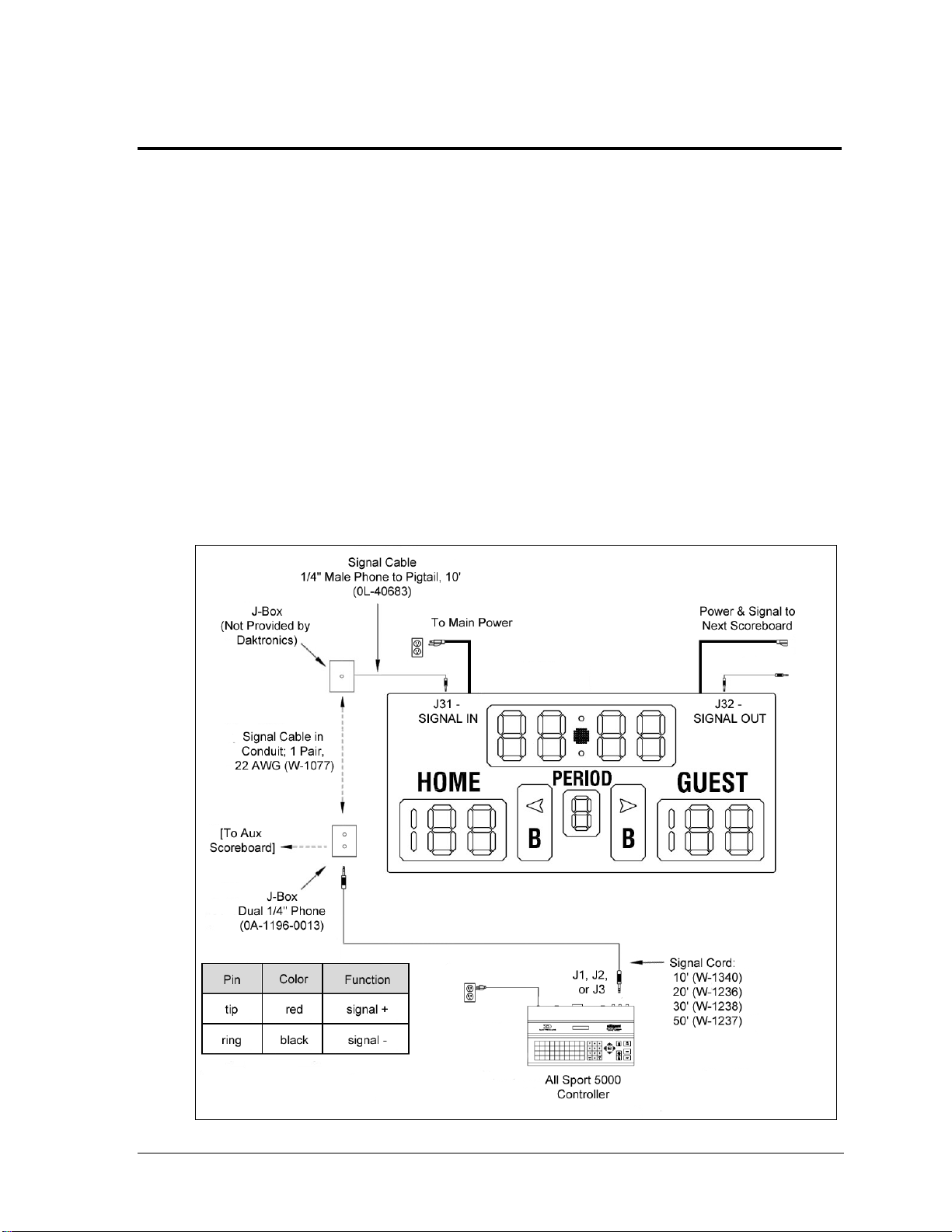
Figure 4: Wired Installation
Section 4: Electrical Installation
CAUTION: Only qualified individuals should access the electrical components of the display and its
associated equipment. It is the responsibility of the electrical contractor to ensure that all electrical
work meets or exceeds local and national codes.
Daktronics engineering staff must approve all changes or the warranty will be void.
4.1 Installation Overview
Electrical installation for four-sided scoreboards involves routing power and control signal
wiring through separate conduit or wire ways to the scoreboard location, as well as routing
power and signal wiring from section to section.
The diagram shown in Figure 4 illustrates a typical wired setup between the first scoreboard
section and the control system. Daktronics part numbers are shown in parentheses.
Note: Control signal cable and some junction boxes are not provided as part of this
system and can be purchased locally or from Daktronics.
Electrical Installation 15
Page 22
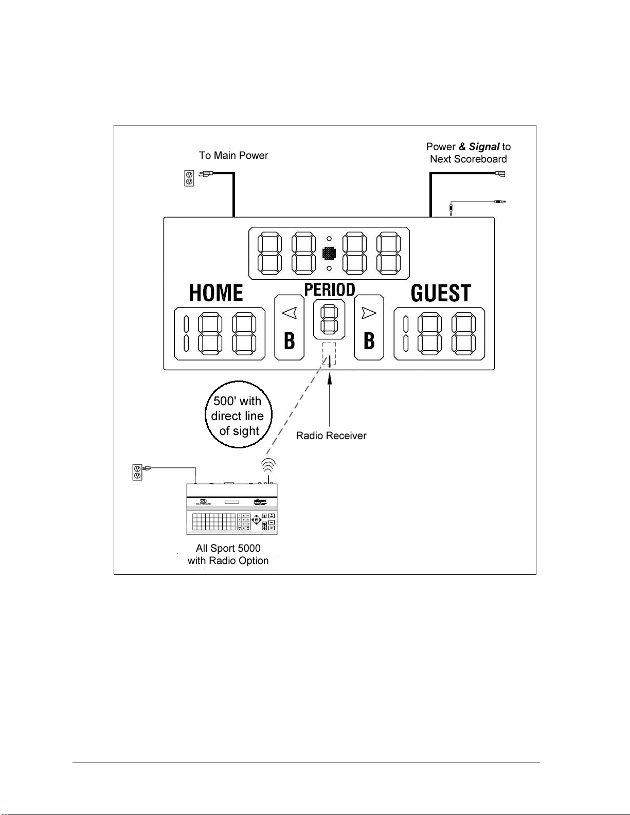
Figure 5: Wireless Installation
The diagram shown in Figure 5 illustrates a typical wireless setup between the first
scoreboard section and the control system. Refer to Section 6.2 for more information about
the wireless radio option.
4.2 Power/Signal Connections Between Sections
Reference Drawing:
Note: Be sure to make sectional power connections before connecting main power! It is also
recommended that these connections are made before the corner shrouds or optional top ad
panels/message centers are mounted into place.
16 Electrical Installation
Ad Panel/Message Center Hookup Overview, 4-Side ............................ Drawing A-154599
Connection Diagram; 4-Sided SS20i Series Displays ............................ Drawing A-822860
Page 23
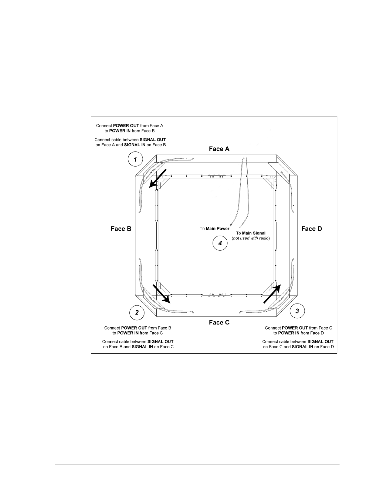
Figure 6: Scoreboard Power & Signal Connection, Top View
Scoreboard power and signal connectors are located on top of the scoreboard cabinet.
Input cables should be routed to the left, and output cables should be routed to the
right (as viewed from the front). The scoreboard section that will receive main
power/signal is designated “Face A”; all other sections are named in relation to it.
Power and signal flows to the right around the display from face output to face input.
Figure 7 shows the power and signal flow between sections. Main power and signal are
terminated last (refer to Sections 4.3 and 4.5, respectively).
Backlit ad panel and message center connectors are located on the sides of the
cabinets. Inputs are on the left, and outputs are on the right (as viewed from the front).
Each message center requires its own power input, while backlit ad panels may be
daisy-chained together for power, like scoreboards. Message center signal connections
use 6-pin RJ45 quick connect cables; main signal may be wired or wireless.
Refer to Drawing A-154599 in Appendix E for connection details of power and signal
from one backlit ad panel or message display section to the next. Refer to Drawing
A-822860 for additional message center connection details.
Electrical Installation 17
Page 24

Figure 7: Digit Segment POST
Note: Standard power cords and signal cables are about 10' (3 m) long. If a hoist is used
for this installation, all main power/signal cables must be long enough to allow the
display to be lowered. An optional sheet metal floor may contain the cables when the
scoreboard is raised. If the scoreboard is static-mounted, the cables only need to be long
enough to provide service. Neatly tie excess lengths out of the way.
4.3 Main Power Connection
Note: Be sure to make sectional power connections before connecting main power!
Each scoreboard section includes two 120 VAC power cords: one for Power In and one for
Power Out.
1. Install a grounded 120 VAC receptacle near the scoreboard/backlit ad panel location
(each message center will require its own power receptacle). Try to mount it so that
the power cord is easily accessible to plug in and hidden from view, such as centered
above the display.
2. Determine which scoreboard/backlit ad panel section is closest to the grounded
receptacle, and plug in its power cord.
The control console requires a 120 VAC receptacle and uses less than 1 A of power.
Displays operating on 230 VAC are also available, and they are shipped equipped with
universal power plugs.
Grounding
Connect the scoreboard to earth ground. Proper grounding assures reliable equipment
operation and protects the equipment against damaging electrical disturbances and lightning.
Daktronics recommends a resistance-to-ground of 10 ohms or less. The electrical contractor
performing the electrical installation can verify ground resistance. Daktronics Sales and
Service personnel can also provide this service. The grounding connection on the power
cord‟s three-prong plug connects to the shell of the scoreboard.
Note: The customer must properly ground the outlet according to local and national
codes. Failure to ground the outlet voids the warranty for the scoreboard.
4.4 Power-On Self-Test (POST)
The scoreboard performs a self-test each time that power is turned on and the control console
is powered off or not attached to the scoreboard. If the control console is attached and
powered on, the self-test does not run, and data from the control console is displayed on the
scoreboard after a brief period of time. Each scoreboard self-test pattern will vary depending
on the scoreboard model, the number of drivers and types of digits. Figure 7 shows an
example of the LED bar test pattern that each digit performs.
18 Electrical Installation
Page 25
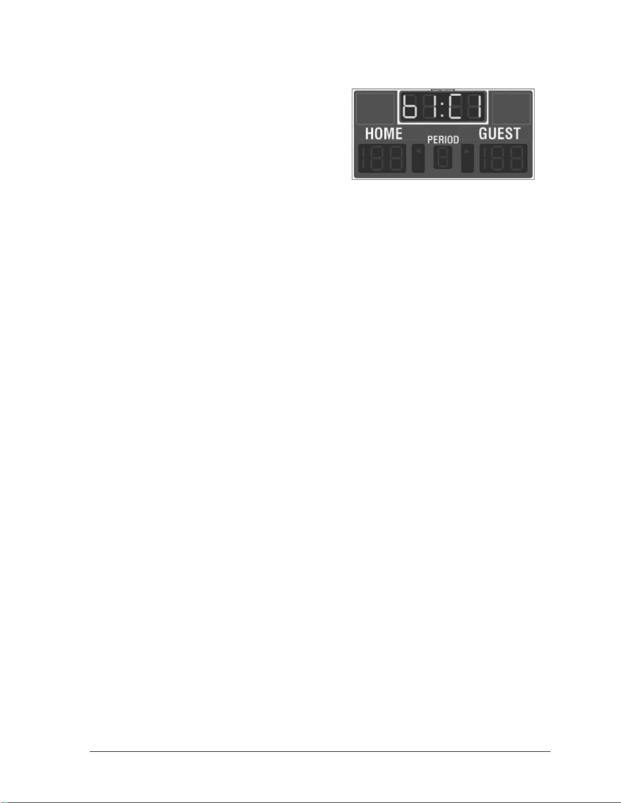
Figure 8: Radio Settings in Clock Digits
Radio Settings
If a radio receiver is installed (see Section 6.2),
the radio broadcast settings (“b1”) and the
channel settings (“C1”) will be displayed in the
Home and Guest or clock digits (Figure 8)
during the POST. These values must match the
settings in the control console (refer to the
appropriate control console manual listed in
Section 1.1).
4.5 Main Signal Connection
Signal installation (for systems without radio control) requires routing control cable from the
scoreboard control console to a signal junction box (J-box) near the display. Refer to Drawing
A-28124 and Drawing A-125316 in Appendix E for signal wire connection.
Note: For message center signal installation, including for BB-2146 and BB-2147 models,
refer to the SS Series 20mm Indoor Scoreboard Message Centers Installation &
Operation Manual (DD1564453).
1. At a minimum, use a paired, 22 AWG shielded cable (Daktronics part # W-1077) and
connect the cable to a dual
Using a dual J-box for separate Main and Auxiliary scoreboards lets operators control
several displays with one controller, and they can also switch jacks to control
individual boards using multiple controllers.
2. Install a J-box near the scoreboard location. Try to mount it so that the signal cable is
easily accessible to plug in and hidden from view, such as centered above the display.
3. Route signal cable from the J-box on the control console end to the J-box at the
display end.
4. Install the
1
/4" phone plug (Daktronics part # 0L-40683) to the display end of the
cable. Be sure to connect the cable shielding only in the J-box on this end.
5. Insert the plug into the J31 - SIGNAL IN jack located on the top of the scoreboard
section closest to the J-box.
6. Connect a signal cable from the J-box on the control console end to the J1, J2, or J3
jack on the back of the All Sport 5000 console.
If using a Main Clock Start/Stop Switch (Daktronics part # 0A-1166-0003), connect it
to the J4 jack on the All Sport 5000 console.
1
/4" J-box at the control console end.
Electrical Installation 19
Page 26

Page 27
Problem
Possible Cause
Solution/Items to Check
Scoreboard doesn’t light
and console doesn’t work
No power to the scoreboard
Check that the main circuit breaker
for the scoreboard is on.
Check that the scoreboard is
receiving 120 (or 230) VAC power.
No power to console
Ensure the console is plugged into a
120 (or 230) VAC power supply.
Swap the console with one known to
work correctly, and enter the proper
sport code to test. Replace console
if necessary.
Scoreboard digits don’t light,
but console works
No wired signal from console
Check that the scoreboard is
receiving 120 (or 230) VAC power.
Check that the red DS2 LED on the
driver lights up when sending
commands from the control console
(see Section 5.4).
No radio signal from console
Cycle power to the scoreboard and
watch for radio receiver broadcast/
channel settings (see Section 4.4).
Check that the green POWER and
amber RADIO IN RANGE indicators
on the radio receiver in the
scoreboard light up when the control
console is powered on. Keep the
console between 20 to 500 feet from
the scoreboard.
Section 5: Maintenance & Troubleshooting
IMPORTANT NOTES:
1. Disconnect power before doing any repair work on the scoreboard.
2. Allow only qualified service personnel access to internal display electronics.
3. Disconnect power when not using the scoreboard.
5.1 Troubleshooting Table
The table below lists potential problems with the scoreboard and indicates possible causes
and corrective actions. This list does not include every symptom that may be encountered,
but it does present several of the most common situations that may occur.
Many of the solutions offered below provide references to other sections within this manual
or to supplemental product manuals with further detail on how to fix the problem.
If a problem occurs that is not listed or that cannot be resolved using the solutions in the
following table, contact Daktronics using the information provided in Section 5.9.
Maintenance & Troubleshooting 21
Page 28
Problem
Possible Cause
Solution/Items to Check
Move the console 20-30 feet from
the scoreboard and test again.
Verify that both the console and
scoreboard antennae are securely
tightened and in a vertical position.
Replace the radio receiver.
No signal to driver
Check that the scoreboard is
receiving 120 (or 230) VAC power.
Check that the red DS2 LED on the
driver lights up when sending
commands from the control console
(see Section 5.4).
Swap the driver with one known to
work correctly and with the same
part number to verify the problem.
Replace if necessary (see Section
5.4).
No power to driver
Check that the green DS1 LED on
the driver is always lit up when the
scoreboard is powered on
(see Section 5.4).
Scoreboard digits light, but
not in the correct order
Incorrect sport code
Ensure the correct sport code is
being used for the scoreboard
model. Refer to the control console
operation manual (see Section 1.1).
Incorrect driver address
Check that the scoreboard driver(s)
are set to the correct address(es)
(see Section 5.4).
Scoreboard digits light,
console works, but no
display on scoreboard
No wired signal from console
(See solution on previous page)
No radio signal from console
(See solution on previous page)
Bad/damaged wiring
Check that the red DS2 LED on the
driver lights up when sending
commands from the control console
(see Section 5.4).
Scoreboard works, but some
LEDs always stay on
Short in digit or indicator circuit
Swap the digit/indicator with one
known to work correctly to verify the
problem. Replace if necessary (see
Section 5.3).
Scoreboard works, but some
LEDs do not light or they
blink
Bad connection
Verify the power/signal connector on
the back of the digit circuit board is
secure (see Section 5.3).
Bad digit or driver
Swap the digit/driver with one known
to work correctly to verify the
problem. Replace if necessary
(see Section 5.3 for digits or
Section 5.4 for drivers).
22 Maintenance & Troubleshooting
Page 29
Problem
Possible Cause
Solution/Items to Check
Scoreboard works, but some
digits do not light
Bad digit or driver
(see solution on previous page)
Incorrect sport code
(see solution on previous page)
Incorrect driver address
(see solution on previous page)
Wrong console controlling
scoreboard
Another console’s radio signal could
be transmitting to the scoreboard.
Radio interference
There may be other radio
transmissions in the area that
overpower the console. If it is not
possible to disable the interfering
device, It may be necessary to run a
wired signal connection instead.
Figure 9: Power Warning Label
Note: For message center maintenance and troubleshooting for BB-2146 and BB-2147 models,
refer to the SS Series 20mm Indoor Scoreboard Message Centers Installation & Operation
Manual (DD1564453).
5.2 Component Location & Access
All Tuff Sport indoor basketball displays are front-access scoreboards, meaning that internal
electronic components and digits are reached by opening a face panel, an access door, or a
digit panel on the front of the display.
Digit panels are typically held in place on the scoreboard face by two screws. To remove a
digit, simply unfasten the screws and carefully lift it from the cabinet. The power/signal plug
can then be removed from the connector on the back of the digit to completely free the digit
and access internal components.
Remove non-digit access panels by unfastening the top, side or bottom screws holding it in
place. Some panels are hinged and swing open when the screws are removed or loosened.
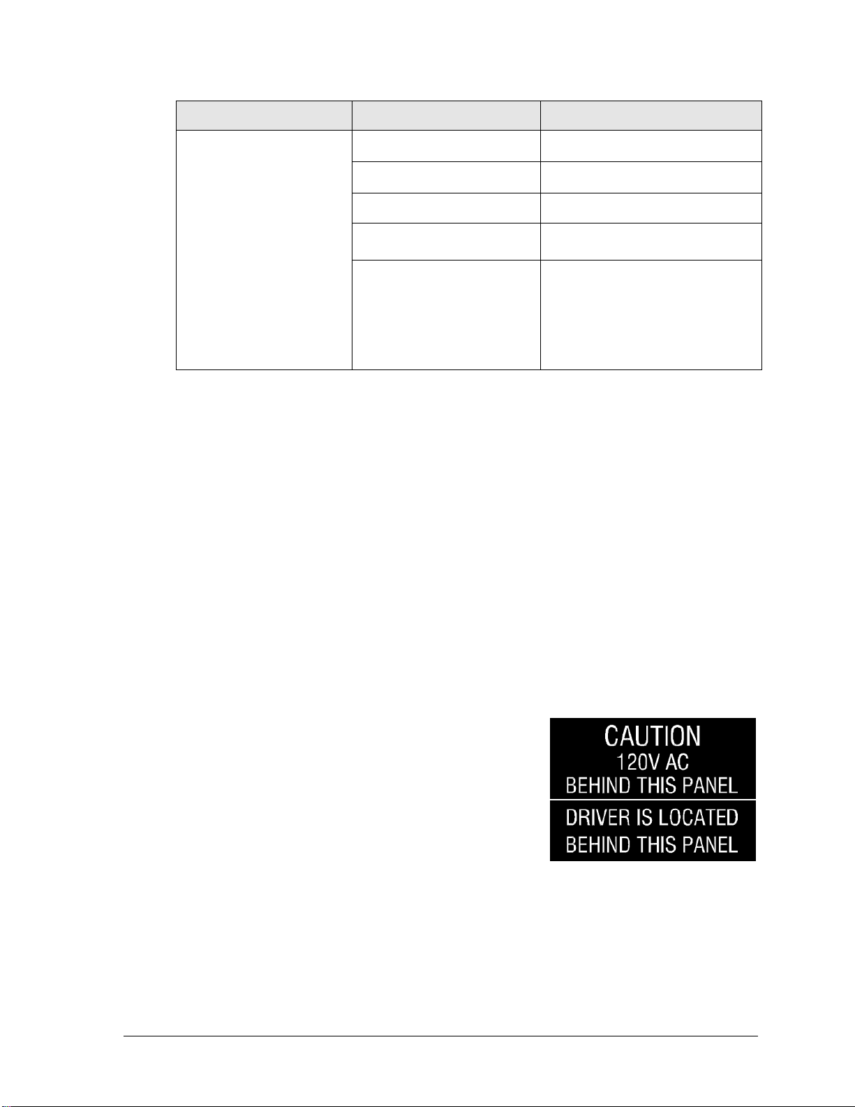
Component location varies with each scoreboard model,
but drivers and power and signal components are
typically mounted inside the scoreboard behind a digit
panel. To locate the driver(s), look for a warning label
similar to that shown in Figure 9.
Refer to the electrical and signal specification drawings in
Appendix B for model-specific component layouts and
access locations.
Maintenance & Troubleshooting 23
Page 30
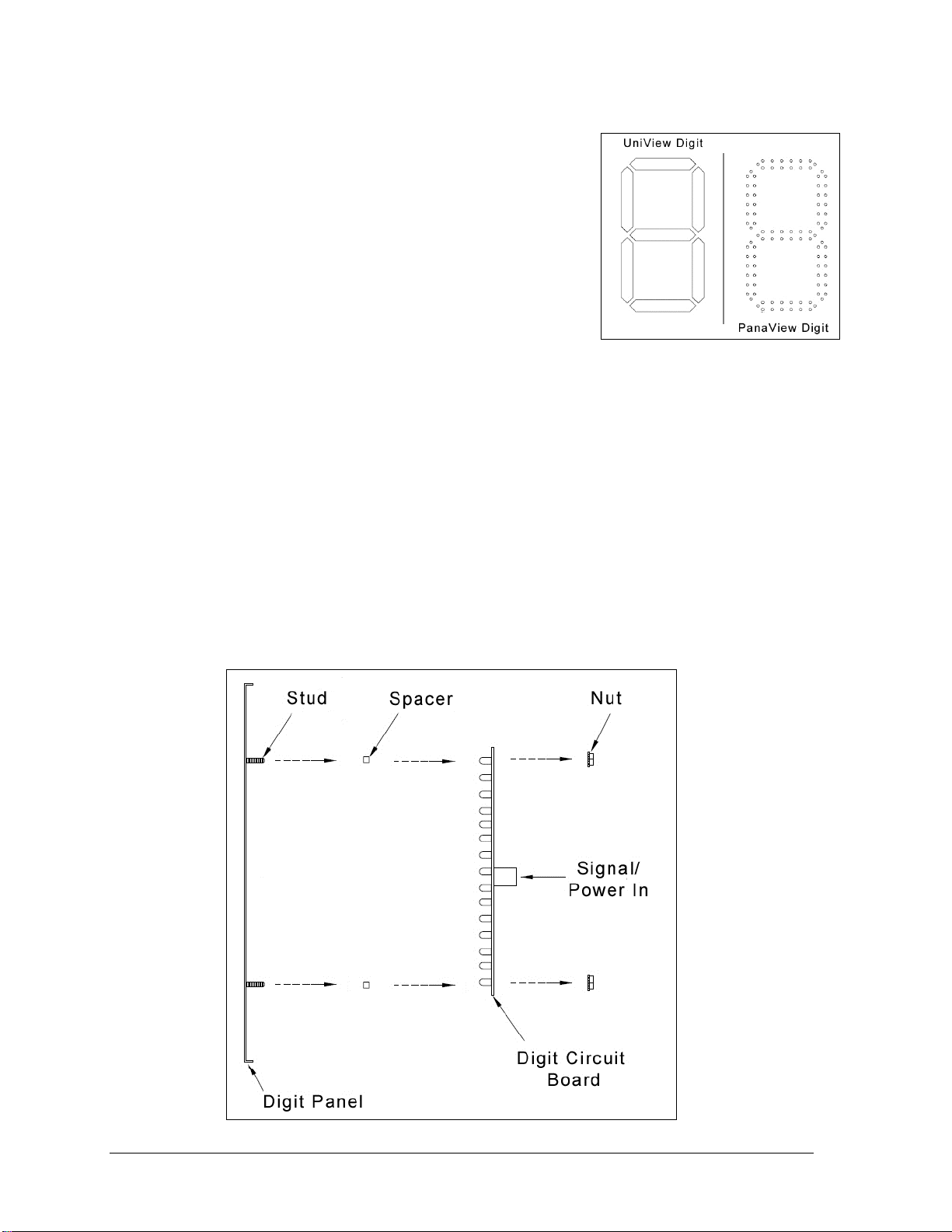
Figure 10: Digit Types
Figure 11: PanaView Digit Assembly
5.3 Replacing Digits
LEDs are embedded in a circuit board that is mounted to the
back of the digit panel. Do not attempt to remove individual
LEDs. In the case of a malfunctioning LED or digit segment,
replace the entire digit circuit board.
The process of replacing digits varies by whether it is a
PanaView digit or UniView digit (Figure 10).
PanaView
To replace a PanaView digit circuit board (Figure 11):
1. Open the digit panel as described in Section 5.2.
2. Disconnect the power/signal connector from the back of the digit by squeezing
together the locking tabs and pulling the connector free.
3. Use a
4. Position a new digit over the studs (making sure the small plastic spacers are still in
5. Reconnect the power/signal connector.
6. Secure the digit panel to the display with the two screws, then power up and test the
9
/32" nut driver to remove the nuts securing the digits to the inside of the panel,
and then lift the digit off the stud inserts.
place) and tighten the nuts.
Note: This is a keyed connector and it will attach in one way only. Do not attempt to
force the connection.
display to see if changing the digit has resolved the problem.
24 Maintenance & Troubleshooting
Page 31

Figure 12: UniView Digit Assembly
UniView
To replace a UniView digit circuit board (Figure 12):
1. Open the digit panel as described in Section 5.2.
2. Disconnect the power/signal connector from the back of the digit by squeezing
together the locking tabs and pulling the connector free.
3. Use a
4. Position a new digit over the standoffs, and tighten the nuts. It may be necessary to
5. Reconnect the power/signal connector.
6. Secure the digit panel to the display with the two screws, then power up and test the
9
/32" nut driver to remove the nuts securing the digits to the aluminum
standoffs, and then lift the digit off the standoff/diffuser assembly.
also tighten the standoffs if they became loose while removing the nuts.
Note: This is a keyed connector and it will attach in one way only. Do not attempt to
force the connection.
display to see if changing the digit has resolved the problem.
Maintenance & Troubleshooting 25
Page 32

Figure 13: Driver Enclosure Location & Components
5.4 LED Drivers
In each scoreboard, one or more LED drivers perform the task of switching LEDs on and off.
LED drivers are located inside of a driver enclosure. Refer to Figure 13 to view the location
and components of a Tuff Sport driver enclosure.
All scoreboards in this manual use 16-column drivers (Figure 13). Some scoreboard models
contain more than one driver to accommodate all of the digits and indicators. Refer to the
electrical and signal specifications in Appendix B to determine the type and number of
drivers for a particular scoreboard model.
Each driver has numerous connectors providing power and signal inputs and outputs to the
scoreboard digits and indicators. The table on the following page shows the function of these
connectors for a 16-column driver:
26 Maintenance & Troubleshooting
Page 33

Connector #
Function
1-16
Output to digits and indicators
17
Control signal
18
Control for horn
19
Address
LED
Color
Function
Operation
Summary
DS1
Green
Power
Steady on
DS1 will be on and steady to indicate the driver
has power.
DS2
Red
Signal RX
Steady on
or blinking
DS2 will be on or blinking when the driver is
receiving a signal and off when there is no signal.
DS3
Amber
Status
Blinking
DS3 will be blinking at one second intervals to
indicate the driver is running.
Figure 14: Driver Status Indicators
Refer to Drawing A-126174 in Appendix E for detailed driver pin out/switch specifications.
When troubleshooting driver problems, three LEDs labeled DS1, DS2, and DS3, provide the
following diagnostic information:
Note: While it is necessary to have the scoreboard powered on to check the LED driver
status indicators, always disconnect scoreboard power before servicing.
Maintenance & Troubleshooting 27
Page 34

Figure 15: Address Jack J19
Replacing a Driver
If the driver status indicators do not appear to be working correctly, it may be necessary to
replace the driver.
1. Open the digit panel or scoreboard face panel as described in Section 5.2.
2. Disconnect all connectors from the driver by squeezing together the locking tabs and
pulling the connectors free.
Note: It may be helpful to label the cables to know which cable goes to which
connector when reattaching the driver.
3. Remove the wing nuts securing the driver to the driver tray.
4. Carefully lift the driver from the display and place it on a clean, flat surface.
5. Position a new driver over the screws and tighten the nuts.
6. Reconnect all power/signal connectors.
Note: The connectors are keyed and will attach in one way only. Do not attempt to
force the connections.
7. Ensure the driver is set to the correct address (refer to Setting the Driver Address).
8. Close and secure the access panel, then power up and test the scoreboard to see if
changing the driver has resolved the problem.
Setting the Driver Address
Since the same LED drivers can be used for many
scoreboard models, each driver must be set to receive
the correct signal input, or address, for the model
being used. This address is set with jumper wires in a
12-pin plug which mates with jack J19 on the driver
(Figure 15).
It may be possible to reuse the same address plug
from the driver that was replaced. If not, first refer to
the specifications table in Section 2 to find the correct
driver address(es) for a particular scoreboard model.
Then refer to Drawing A-115078 in Appendix E for a
listing of the wire/pin connections for driver
addresses 1 – 128.
Multiple Drivers
Scoreboards that require multiple drivers operate using a master/slave driver configuration.
Master and slave drivers function identically, but slave units lack the power/signal
termination blocks. The two drivers have been designed to simply plug into one another, and
this is done at the factory, so no additional on-site connection is necessary.
If it appears as though only a certain group of digits on the scoreboard is not functioning,
there may be a problem with the slave driver(s) or the power/signal connection from the
other driver(s).
28 Maintenance & Troubleshooting
Page 35

Model
Drawing Title
Drawing Number
BB-2102 BB-2146
BB-2104 BB-2147
BB-2106 BB-2154
BB-2108 BB-2156
BB-2126
Schematic- 16V 1 Driver- 120 or 230VAC
A-158348
BB-2124
Schematic, 16V 2 Driver, 120 or 230 VAC
B-158859
5.5 Segmentation and Digit Designation
In each digit, certain LEDs always go on and off together. These groupings of LEDs are called
segments. Drawing A-38532 in Appendix E details which connector pin is wired to each digit
segment and the wiring color code used throughout the display.
The electrical and signal specification drawings in Appendix B specify the driver connectors
controlling the digits. Numbers shown in hexagons in the upper half of each digit indicate
which connector is wired to that digit.
5.6 Schematics
For advanced scoreboard troubleshooting and repair, it may be necessary to consult the
schematic drawings. Located in Appendix D, schematic drawings show detailed power and
signal wiring diagrams of internal display components such as drivers, horn interface cards,
and transformers as well as optional components like TNMCs and radio receivers.
5.7 Suspension System Periodic Inspections
Suspension systems need to be inspected periodically. Listed below are instructions and
information about such inspections.
Static System
A static-hung system should be inspected one year after initial installation and once every
five years thereafter.
Inspect cable assemblies for broken wires, crushes, or kinks.
Inspect components, per manufacturer's recommendations, for deformations.
Inspect the four-sided scoreboard for any loose or missing bolts.
Inspect the attachment bracket for loose bolts or cracks in members or welds.
Check torque on all wire rope clips.
Hoist System
Hoist systems must be inspected annually per OSHA requirements. Some local governing
bodies require more frequent inspections. See the hoist manufacturer's manual for inspection
procedures.
Inspect cable assemblies for broken wires, crushes, or kinks.
Inspect connections for loose bolts or cracks in members or welds.
Be sure to document all inspections. Any irregularities must be addressed immediately.
For installation problems, call the original installer; for hoist problems, contact the hoist
Maintenance & Troubleshooting 29
manufacturer.
Page 36

Description
Daktronics Part #
Horn, 120V with capacitor
0A-1152-0332
Main clock, start/stop switch
0A-1166-0003
Shot clock, start/stop switch
0A-1196-0031
LED driver, 16-column
0P-1150-0126
16 V AC LED VHI
0P-1150-0233
PanaView Digit, 7” red LED, 7-seg
0P-1230-0048
PanaView Digit, 7” amber LED, 7-seg
0P-1230-0049
PanaView Digit, 7” red LED, 2-seg
0P-1230-0058
PanaView Digit, 7” amber LED, 2-seg
0P-1230-0059
PanaView Digit, 10” red LED, 7-seg
0P-1230-0050
PanaView Digit, 10” amber LED, 7-seg
0P-1230-0051
PanaView Digit, 10” red LED, 2-seg
0P-1230-0060
PanaView Digit, 10” amber LED, 2-seg
0P-1230-0061
PanaView Digit, 13” red LED, 7-seg
0P-1230-0052
PanaView Digit, 13” amber LED, 7-seg
0P-1230-0053
PanaView Digit, 13” red LED, 2-seg
0P-1230-0062
PanaView Digit, 13” amber LED, 2-seg
0P-1230-0063
PanaView B-Bonus Indicator, Amber
0P-1150-0217
PanaView Arrow, Red, 3”
0P-1150-0185
PanaView Arrow, Amber, 3”
0P-1150-0164
PanaView Colon, Red
0P-1230-0070
PanaView Colon, Amber
0P-1230-0071
UniView Digit, 7” Red LED, 7-seg
0P-1230-0023
UniView Digit, 7” Amber LED, 7-seg
0P-1230-0024
UniView Digit, 7” Red LED, 2-seg
0P-1230-0031
UniView Digit, 7” Amber LED, 2-seg
0P-1230-0032
UniView Digit, 10” Red LED, 7-seg
0P-1230-0025
UniView Digit, 10” Amber LED, 7-seg
0P-1230-0026
UniView Digit, 10” Red LED, 2-seg
0P-1230-0033
UniView Digit, 10” Amber LED, 2-seg
0P-1230-0034
UniView Digit, 13” Red LED, 7-seg
0P-1230-0027
UniView Digit, 13” Amber LED, 7-seg
0P-1230-0028
UniView Digit, 13” Red LED, 2-seg
0P-1230-0035
UniView Digit, 13” Amber LED, 2-seg
0P-1230-0036
UniView 1 Position Indicator, Red
0P-1230-0037
UniView 3 Position Indicator, Red & Amber
0P-1230-0038
UniView B-Bonus Indicator & Arrow, Amber
0P-1230-0039
UniView Colon, Red
0P-1230-0068
UniView Colon, Amber
0P-1230-0069
Transformer, 120P/16S, 6.3 A
T-1066
Cable, 20' phone plug
W-1236
Cable, 50' phone plug
W-1237
Cable, 30' phone plug
W-1238
Cable, 10' phone plug
W-1340
5.8 Replacement Parts List
Refer to the following table for Daktronics scoreboard replacement parts.
30 Maintenance & Troubleshooting
Page 37

Market Description
Customer Service Number
Schools (including community/junior colleges), religious
organizations, municipal clubs and community centers
877-605-1115
Universities and professional sporting events, live events
for auditoriums and arenas
866-343-6018
5.9 Daktronics Exchange and Repair & Return Programs
Exchange Program
The Daktronics Exchange Program is a quick, economical service for replacing key
components in need of repair. If a component fails, Daktronics sends a replacement part to
the customer who, in turn, returns the failed component to Daktronics. This not only saves
money but also decreases equipment downtime. Customers who follow the program
guidelines explained below will receive this service.
Before Contacting Daktronics
Identify these important numbers:
Display Serial Number: _________________________________________________________
Display Model Number: _________________________________________________________
Job/Contract Number: __________________________________________________________
Date Installed: _________________________________________________________________
Daktronics Customer ID Number: ________________________________________________
To participate in the Exchange Program, follow these steps.
1. Call Daktronics Customer Service.
2. When the new exchange part is received, mail the old part to Daktronics.
If the replacement part fixes the problem, send in the problem part being replaced.
a. Package the old part in the same shipping materials in which the replacement
part arrived.
b. Fill out and attach the enclosed UPS shipping document.
c. Ship the part to Daktronics.
3. The defective or unused parts must be returned to Daktronics within 5 weeks of
initial order shipment.
If any part is not returned within five (5) weeks, a non-refundable invoice will be
presented to the customer for the costs of replenishing the exchange parts inventory
with a new part.
Daktronics reserves the right to refuse parts that have been damaged due to acts of
nature or causes other than normal wear and tear.
Maintenance & Troubleshooting 31
Page 38

Repair & Return Program
For items not subject to exchange, Daktronics offers a Repair & Return Program. To send a
part for repair, follow these steps:
1. Call or fax Daktronics Customer Service:
Refer to the appropriate market number in the chart listed on the previous page.
Fax: 605-697-4444
2. Receive a case number before shipping.
This expedites repair of the part.
3. Package and pad the item carefully to prevent damage during shipment.
Electronic components, such as printed circuit boards, should be placed in an
antistatic bag before boxing. Daktronics does not recommend using packing „peanuts‟
when shipping.
4. Enclose:
name
address
phone number
the case number
a clear description of symptoms
Shipping Address
Daktronics Customer Service
[Case #]
201 Daktronics Drive, Dock E
Brookings, SD 57006
Daktronics Warranty and Limitation of Liability
The Daktronics Warranty and Limitation of Liability is located in Appendix G. The Warranty
is independent of Extended Service agreements and is the authority in matters of service,
repair, and display operation.
32 Maintenance & Troubleshooting
Page 39

Section 6: Scoreboard Options
6.1 Horns
Daktronics Tuff Sport scoreboards are equipped with a 120 VAC vibrating horn mounted
behind the scoreboard face. The horn sounds automatically when the period clock counts
down to zero, or when manually triggered by the operator using the control console.
Installation of an optional 12 VDC horn is detailed in Drawing A-148960 in Appendix C.
Louder trumpet horns are also available. Contact Daktronics for information and pricing.
Adjusting Horn Volume
CAUTION: The scoreboard horn is a 120 VAC device. Turn off the power to the scoreboard
before adjusting the horn.
The volume for the electronic, buzzer-type horn is set at its maximum level at the factory. If
the horn is too loud, reduce its volume by adjusting the setscrew mounted in the front of the
horn. A plastic tip on the screw touches the horn's diaphragm, reducing the volume. Turn the
screw clockwise and test the volume by operating the horn from the scoreboard control
console. Continue adjusting and testing until the desired volume level is obtained.
Note that with the noise of spectators, the horn will not seem as loud as when it is being
tested in an empty area, so be sure to set the volume according to the acoustics of the facility.
6.2 Radio Control
Radio control is an option for Daktronics Tuff Sport scoreboards. The system provides
scoreboard control via a 2.4 GHz, extra-high frequency FM signal.
The radio transmitter and receiver are not standard equipment. This setup requires a control
console equipped with a radio transmitter as well as a radio receiver plugged into the
driver/power enclosure and mounted internally to the front panel of the scoreboard.
For additional information about this option, contact a Daktronics representative; for
complete information on setting up radio communication control, refer to the Gen V Radio
Installation Manual (ED-13831) or the Gen VI Radio Installation Manual (DD2362277),
both available online at www.daktronics.com/manuals.
6.3 Visual Horn Indicator (VHI)
In addition to the horn, Daktronics offers both incandescent and LED visual horn indicators
that light up when the buzzer sounds. To install the VHI, users must tap into the existing
horn wiring to provide power and signal. For more information about installing the VHI
options, refer to the Visual Horn Indicator Installation Instructions (ED-13397) or the
BB-2133 LED Indicator Installation Instructions (ED-13806). Both manuals are available
online at www.daktronics.com/manuals.
Scoreboard Options 33
Page 40

6.4 Changeable Captions
Team name and statistics caption kits contain hardware for one caption only and consist of an
upper caption retainer, a lower caption retainer, a changeable caption panel and screws.
The standard HOME and GUEST captions are applied directly to the face of the scoreboard.
Team name captions are on changeable panels that fit into retainers mounted above and
below the standard captions. If these retainers are not already present, attach the retainers
included with the caption kit.
Refer to Drawing A-150021 in Appendix C for changeable caption installation instructions.
6.5 Double Bonus Indicators
All of the clock/score basketball scoreboards in this manual have the option to include
double-bonus indicators, which are factory installed. This option is illustrated in the electrical
and signal specification drawings in Appendix B for each scoreboard model.
6.6 Time Outs Left (TOL) Digits
Certain scoreboards have the option to add a time outs left (TOL) digit for both the home and
guest teams. These digits are installed by simply unscrewing the blank face panel, connecting
and securing the digit, and manually applying the “T.O.L.” caption. Refer to Drawing A-
149030 in Appendix C for more information.
6.7 Team Name Message Centers
Refer to Section 7 for more information about Team Name Message Centers.
34 Scoreboard Options
Page 41

Matrix Size
Number of
Modules
Pixel Spacing
Active Display Area
Weight*
8x48
3
19 mm (0.75")
6" x 36" (152 mm x 914 mm)
15 lb (7 kg)
Figure 16: Basketball Scoreboard with TNMCs
TNMC
Section 7: TNMC Troubleshooting & Maintenance
IMPORTANT NOTES:
1. Always disconnect scoreboard power before doing any repair/maintenance work on the
message centers.
2. Permit only qualified service personnel to access internal display electronics.
3. Disconnect power when not using the scoreboard.
7.1 Display Overview
Team Name Message Centers (TNMCs) are programmable LED displays that allow users to
show custom Home and Guest names or messages of ~15 characters on the scoreboard in
place of static vinyl captions. TNMCs are typically ordered factory-installed, but they may
also be field-mounted after the scoreboard is in place. Characters are shown on one line using
single- or double-stroke fonts.
Primary matrix size is 8x48 with 0.75" pixel spacing. Figure 16 shows an example of TNMCs.
* Weight shown is for a pair of displays.
TNMC Maintenance & Troubleshooting 35
Page 42

Symptom/Condition
Possible Remedy
One or more LEDs on a single
module fails to light
Check/replace the ribbon cables on the module.
Replace the module (see Section 7.7).
One or more LEDs on a single
module fails to turn off
Check/replace the ribbon cables on module.
Replace the module (see Section 7.7).
A section of the display not
working; section extends all the
way to the right side of the display
Check/replace the ribbon cables running to the first module
that is not working.
Replace the first module on the left side of the first module
that is not working (see Section 7.7).
Replace the second module that is not working
(see Section 7.7).
Replace the power supply assembly on the first module that is
not working (see Section 7.8).
One row of modules does not work
or is garbled
Replace the first module (see Section 7.7).
Replace the display driver (see Section 7.6).
A group of modules that share the
same power supply assembly fails
to work
Replace the power supply assembly (see Section 7.8).
Entire display fails to work
Check for proper line voltage into the power termination panel.
Check/replace the ribbon cable from the display driver to the
modules.
Check the voltage settings on the power supplies.
Check/replace the signal cable to the driver.
Repair/replace the driver (see Section 7.6).
7.2 Initialization Information at Startup
Every time the display is powered up and there is no All Sport® signal present, the display
will run through an initialization process, during which it will test all LEDs and addresses.
First, the message center will display the proper address number.
If the entire display fails at startup, power may not be properly connected, or the address
setting may not be correct on the display driver. Check both in the event of a failure.
7.3 Display Troubleshooting Table
The table below lists potential problems with the display and indicates possible causes and
corrective actions. This list does not include every symptom that may be encountered, but it
does present several of the most common situations that may occur.
Many of the solutions offered below provide references to other sections within this manual
with further detail on how to fix the problem.
If a problem occurs that is not listed or that cannot be resolved using the solutions in the
following table, contact Daktronics using the information provided in Section 5.9.
36 TNMC Maintenance & Troubleshooting
Page 43

7.4 Power & Signal Summary
Reference Drawings:
Schematic: 3/4" and 1" DC TNMC’s ...................................................... Drawing B-146975
Refer to Drawing B-146975 in Appendix D for detailed schematics about display power and
signal routing.
Display signal routing can be summarized as follows:
1. Data from the All Sport
2. The signal then travels through the driver, typically re-driven from the driver TB-31
to the current loop interface (CLI) cards located on the right-hand module of each
display.
3. A ribbon cable harness carries the signal to the first LED module, and the signal
relays from module to module via ribbon cable in daisy-chain style until it reaches
the last module in the display.
Display power routing can be summarized as follows:
1. Incoming power from the power cord terminates at the main scoreboard LED driver tray.
2. Using interconnect harnesses, the power is passed from the driver tray to the Home
display power supply, and then to the Guest display power supply.
3. Power from the power supplies is relayed to all display modules.
4. The modules draw their power directly from the power supply assemblies; the
display driver receives power out from the first module via ribbon cable.
®
controller travels via signal cable (or radio) into the scoreboard.
7.5 Component Locations & Access
Reference Drawings:
Installation, 6" Amber 8x48 TNMC .......................................................... Drawing A-148701
To access the internal components of the display, simply remove the two screws on either
side of the face panel that secure it to the scoreboard. Carefully remove the face panel from
the scoreboard, as there will be several cables connected to it.
Drawing A-148701 in Appendix C provides a detailed view of each display component and
the connections between them.
7.6 Display Drivers
Reference Drawings:
A/S 5000 Capable TNMC Shift Card; Specifications .............................. Drawing A-123794
Display drivers, also known as controllers or shift cards, use a 12-pin plug that mates with
jack J4 to set the address. For TNMCs, the address plug is set to 1 (221). Pin 11 on the address
plug selects whether the display shows Guest (default) or Home data. Refer to Drawing
A-123794 in Appendix E for addressing information.
TNMC Maintenance & Troubleshooting 37
Page 44

LED Name
Color
Illumination Summary
DS1 PWR
Green
Steady on or blinking when the driver has power
DS2 RX
Red
Steady on or blinking when the driver is receiving
and off when there is no current loop (CL) signal
Figure 17: Display Driver
Figure 17 illustrates some of the primary jacks and indicators of a display driver.
Diagnostic LEDs
The following table explains the functions of the primary diagnostic LEDs on the drivers:
Replacing a Driver
1. Access the internal components as described in Section 7.5.
2. Disconnect all power and signal connectors from the driver by squeezing together the
locking tabs and pulling the connectors free.
Note: It may be helpful to label the cables to know which cable goes to which
connector when reattaching a driver.
3. Remove the four screws securing the driver to the module. This will be the right-most
module, when viewing the display from the front.
4. Position a new driver over the standoffs on the module and tighten the screws.
5. Reconnect all power/signal connectors.
6. Power up and test the scoreboard/display to see if the problem has been resolved.
Refer to Figure 18 for an overview of driver (and module) replacement.
38 TNMC Maintenance & Troubleshooting
Page 45

Figure 18: Replacing a Module or Driver, Top View
7.7 Modules
Display modules consist of LEDs embedded in a circuit board. One or more circuit boards are
mounted to the back of a display face panel. Do not attempt to remove individual LEDs. In
the case of malfunctioning LEDs, replace the entire module circuit board.
Replacing Modules
1. Access the internal components as described in Section 7.5.
2. Carefully disconnect all ribbon cables from the driver by squeezing together the
locking tabs and pulling the connectors free.
Note: It may be helpful to label the cables to know which cable goes to which
connector when reattaching.
3. Remove the nuts securing the module circuit board to the face panel. If a display
driver is attached to the module, remove it along with the screws and standoffs.
4. Position a new module on the front of the face panel and reconnect all ribbon cables.
5. Reattach the module to the face panel. If a display driver was previously removed
from the module, reattach it at this time too.
6. Power up and test the scoreboard/display to see if the problem has been resolved.
Refer to Figure 18 for an overview of module (and driver) replacement.
TNMC Maintenance & Troubleshooting 39
Page 46

Part Description
Part Number
Indoor TNMC Card
0P-1150-0206
Module; 8x16, Amber
0P-1186-0112
Power Supply; 5V @ 10A, 85-264VAC
A-1568
Cable; 18 pos, Ribbon, 6"
W-1320
7.8 Power Supplies
Replacing a Power Supply
1. Access the internal components as described in Section 7.5.
2. Remove the two screws securing the power supply bracket, and remove it from the
display cabinet.
3. Disconnect all the wires connected to the power supply.
Note: It may be helpful to label the cables to know which cable goes to which
connector when reattaching.
4. Remove the three screws securing the power supply to the bracket, and attach the
new power supply to it.
5. Reconnect all wires, and mount the power supply bracket inside the display cabinet.
7.9 Display Maintenance
Complete a yearly inspection to maintain safe and dependable display operation.
This inspection should address the following issues:
Loose Hardware: Verify that fasteners, such as bolts and rivets, have not come loose.
Check and tighten or replace fasteners as required.
Excessive Dust Buildup: It may be necessary to occasionally vacuum the inside of
the display cabinet to remove dust/dirt buildup that may interfere with airflow.
Corrosion: Check the paint, and look for possible corrosion.
Note: If any of the preceding conditions are discovered, make the necessary repairs or take
corrective action immediately.
7.10 Replacement Parts List
The following tables contain display components that may have to be replaced. Many of the
components within the display itself have attached part number labels.
See Section 5.9 for information on Daktronics Exchange and Repair and Return program.
40 TNMC Maintenance & Troubleshooting
Page 47

Appendix A: Mechanical Specification Drawings
Drawing Title Drawing Number
Mechanical Spec, BB-2102 ...................................................................................................... B-148777
Mechanical Spec, BB-2104 ...................................................................................................... B-148922
Mechanical Spec, BB-2106 ...................................................................................................... B-148923
Mechanical Spec, BB-2108 ...................................................................................................... B-148924
Mechanical Spec, BB-2124 ...................................................................................................... B-165593
Mechanical Spec, BB-2126 ...................................................................................................... B-167572
Mechanical Spec- BB-2147 ...................................................................................................... B-267980
Mechanical Spec- BB-2146 ...................................................................................................... B-319838
Mechanical Spec, BB-2154 .................................................................................................... B-1126896
Mechanical Spec, BB-2156 .................................................................................................... B-1126897
Mechanical Specification Drawings 41
Page 48

Page 49

Page 50
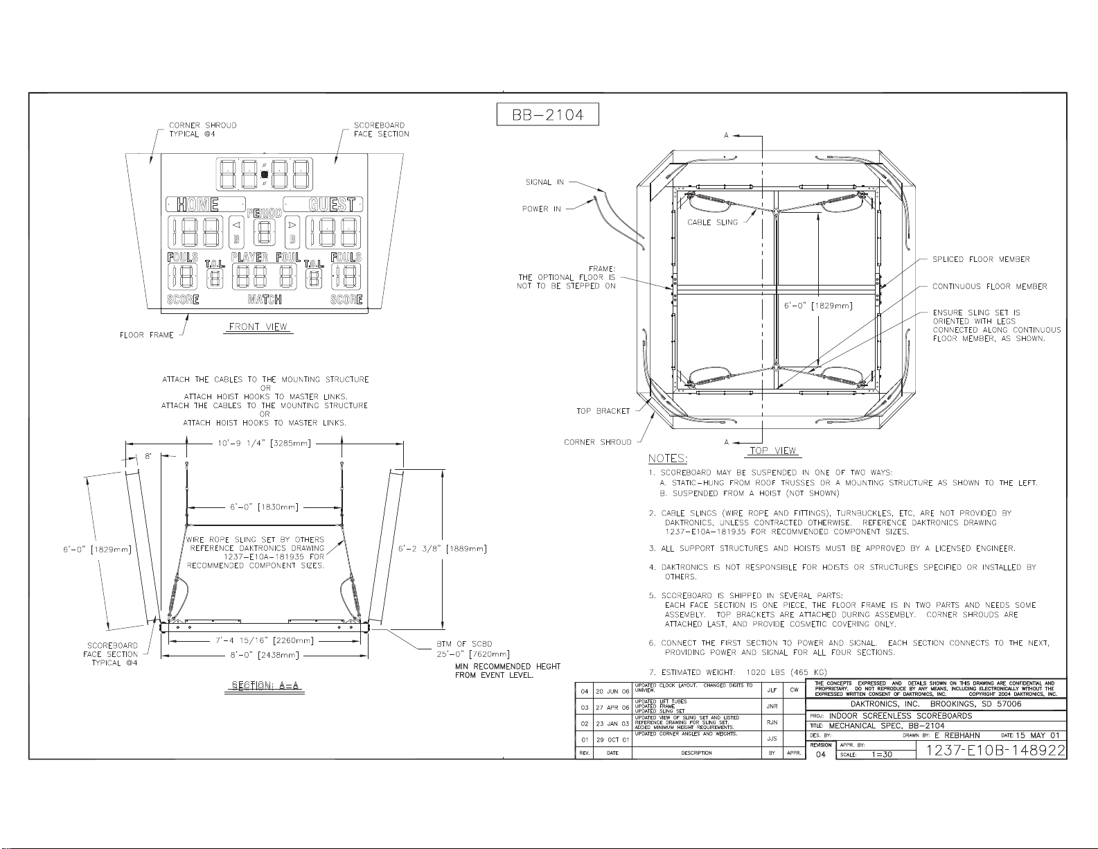
Page 51

Page 52

Page 53

Page 54

Page 55

daktronicsdaktronics
PERIOD
BB
B B
PERIOD
WIRE ROPE SLING SET BY OTHERS
REFERENCE DAKTRONICS DRAWING
1237-E10ARECOMMENDED COMPONENT SIZES.
FOR
MIN RECOMMENDED HEIGHT
FROM EVENT LEVEL
Page 56

daktronics
B B
PERIOD
DAKTRONICS
GUESTHOME
Page 57

%+
>PP@
6&25(%2$5'
)$&(6(&7,21
7<3,&$/#
)/225)5$0(
r
&251(56+528'
7<3,&$/#
GUESTHOME
B B
T.O.L. T.O.L.
)52179,(:
$77$&+7+(&$%/(6727+(02817,1*6758&785(
$77$&++2,67+22.6720$67(5/,1.6
$77$&+7+(&$%/(6727+(02817,1*6758&785(
$77$&++2,67+22.6720$67(5/,1.6
:,5(523(6/,1*6(7%<27+(56
5()(5(1&('$.7521,&6'5$:,1*
5(&200(1'('&20321(176,=(6
25
25
>PP@
>PP@
($)25
>PP@
>PP@
6(&7,21 $$
6&25(%2$5'
)$&(6(&7,21
>PP@
%702)6&%'
>PP@
0,15(&200(1'('+(*+7
)520(9(17/(9(/
%%
6,*1$/,1
32:(5,1
7+(237,21$/)/225,6
12772%(67(33('21
&251(56+528'
)5$0(
723%5$&.(7
$
&$%/(6/,1*
63/,&(')/2250(0%(5
&217,18286)/2250(0%(5
>PP@
$
127(6
6&25(%2$5'0$<%(6863(1'(',121(2)7:2:$<6
$67$7,&+81*)520522)75866(625$02817,1*6758&785($66+2:1727+(/()7
%6863(1'(')520$+2,671276+2:1
&$%/(6/,1*6:,5(523($1'),77,1*67851%8&./(6(7&$5(1273529,'('%<
'$.7521,&681/(66&2175$&7('27+(5:,6(5()(5(1&('$.7521,&6'5$:,1*
($)255(&200(1'('&20321(176,=(6
$//68332576758&785(6$1'+2,6760867%($33529('%<$/,&(16('(1*,1((5
'$.7521,&6,61275(63216,%/()25+2,676256758&785(663(&,),('25,167$//('%<
27+(56
6&25(%2$5',66+,33(',16(9(5$/3$576
($&+)$&(6(&7,21,621(3,(&(7+()/225)5$0(,6,17:23$576$1'1(('6620(
$66(0%/<723%5$&.(76$5($77$&+(''85,1*$66(0%/<&251(56+528'6$5(
$77$&+('/$67$1'3529,'(&260(7,&&29(5,1*21/<
&211(&77+(),5676(&7,217232:(5$1'6,*1$/($&+6(&7,21&211(&76727+(1(;7
3529,',1*32:(5$1'6,*1$/)25$//)2856(&7,216
(67,0$7(':(,*+7/%6.*
7239,(:
'$.7521,&6,1&
,1'2256&5((1/(666&25(%2$5'6
0(&+$1,&$/63(&%%
.'5$*7
6+((7 -2%125(9
3 (
(1685(6/,1*6(7,6
25,(17(':,7+/(*6
&211(&7('$/21*&217,18286
)/2250(0%(5$66+2:1
7+(&21&(376(;35(66('$1''(7$,/66+2:1217+,6
'5$:,1*$5(&21),'(17,$/$1'35235,(7$5<'2127
5(352'8&(%<$1<0($16:,7+2877+((;35(66('
:5,77(1&216(172)'$.7521,&6,1&
&23<5,*+7'$.7521,&6,1&
'5$:1 '$7(
.'5$*7 )(%
%
Page 58

%+
PERIOD
GUESTHOME
B B
T.O.L. T.O.L.
'$.7521,&6,1&
,1'2256&5((1/(666&25(%2$5'6
0(&+$1,&$/63(&%%
.'5$*7
6+((7 -2%125(9
'5$:1 '$7(
3 (
7+(&21&(376(;35(66('$1''(7$,/66+2:1217+,6
'5$:,1*$5(&21),'(17,$/$1'35235,(7$5<'2127
5(352'8&(%<$1<0($16:,7+2877+((;35(66('
:5,77(1&216(172)'$.7521,&6,1&
.'5$*7 )(%
&23<5,*+7'$.7521,&6,1&
%
Page 59

Appendix B: Electrical Specification Drawings
Drawing Title Drawing Number
Electrical and Signal Spec- BB-2107 and BB-2108 .................................................................. A-158571
Electrical and Signal Spec- BB-2101 and BB-2102 .................................................................. A-158845
Electrical and Signal Spec- BB-2103 and BB-2104 .................................................................. A-158848
Electrical and Signal Spec- BB-2105 and BB-2106 .................................................................. A-158849
Electrical and Signal Spec- BB-2123 and BB-2124 .................................................................. A-165429
Electrical and Signal Spec- BB-2125 and BB-2126 .................................................................. A-167240
Electrical and Signal Spec- BB-2153 and BB-2154 ................................................................ A-1104976
Electrical and Signal Spec- BB-2155 and BB-2156 ................................................................ A-1124199
Electrical Specification Drawings 43
Page 60

Page 61

SCORE MATCH SCORE
T.O.L.
HOME
FOULS
GUEST
T.O.L.
BB
PLAYER FOUL
PERIOD
FOULS
daktronics
SCORE MATCH SCORE
FOULT.O.L.
HOME
FOULS
PERIOD
PLAYER
B
daktronics
GUEST
B
T.O.L. FOULS
B B
B B
Page 62

PERIOD
GUESTHOME
HOME
PERIOD
GUEST
B B
B B
B B
Page 63

T.O.L.T.O.L.
HOME GUEST
FOULS PLAYER FOUL FOULS
SCOREMATCHSCORE
PERIOD
PERIOD
SCORE MATCH SCORE
FOULS
T.O.L.
FOULPLAYER
T.O.L.
FOULS
GUESTHOME
B B
B B
PERIOD
B B
Page 64

HOME GUEST
PERIOD
HOME GUEST
PERIOD
B B
BB
B B
BB
Page 65

HOME GUEST
BB
PERIOD
daktronics
B B
GUEST
PLYRFOULS FOUL PTS
B
HOME
PERIOD
B
FOULS
FOULSPTSFOULPLYR
Pending
Patent
daktronics
B B
Page 66

B B
FOULS
SCORE
T.O.L.FOULPLAYER
PERIOD
MATCH
GUEST
T.O.L.FOULS
SCORE
HOME
BB
daktronics
daktronics
SCORE
FOULS T.O.L.
MATCH
PLAYER FOUL T.O.L.
SCORE
FOULS
PERIOD
HOME GUEST
B B
BB
B B
Page 67

THE CONCEPTS EXPRESSED AND DETAILS SHOWN ON THIS
DRAWING ARE CONFIDENTIAL AND PROPRIETARY. DO NOT
REPRODUCE BY ANY MEANS WITHOUT THE EXPRESSED
WRITTEN CONSENT OF DAKTRONICS, INC.
COPYRIGHT 2012 DAKTRONICS, INC.
DAKTRONICS, INC.
AV
DRAWN: DATE:
SHEET JOB NO:REV
TUFF SPORT SCOREBOARDS
ELECTRICAL AND SIGNAL SPEC; BB-2153 AND BB-2154
MJOHNSO 9 JUL 12
P1237 E
10 A
1=40
JVANAAR
1104976
01
GUESTHOME
T.O.L. T.O.L.
GUESTHOME
B B
T.O.L. T.O.L.
B B
B B
DATE:REV BY:
01 07 FEB 13 KDD
ADDED BB-2154 TO DWG
Page 68

THE CONCEPTS EXPRESSED AND DETAILS SHOWN ON THIS
DRAWING ARE CONFIDENTIAL AND PROPRIETARY. DO NOT
REPRODUCE BY ANY MEANS WITHOUT THE EXPRESSED
WRITTEN CONSENT OF DAKTRONICS, INC.
COPYRIGHT 2013 DAKTRONICS, INC.
DAKTRONICS, INC.
AV
DRAWN: DATE:
SHEET JOB NO:REV
TUFF SPORT SCOREBOARDS
ELECTRICAL AND SIGNAL SPEC, BB-2155 AND BB-2156
KDRAGT 14 JAN 13
P1237 E
10 A
1=40
KDRAGT
1124199
01
HOME GUEST
BB
PERIOD
daktronics
HOME
PERIOD
B
daktronics
GUEST
B
B B
B B
T.O.L. T.O.L.
T.O.L. T.O.L.
DATE:REV BY:
01 07 FEB 13 KDD
ADDED BB-2156 TO DWG
Page 69

Appendix C: Scoreboard Options
Drawing Title Drawing Number
Bottom 4-Side Ad Panel Mounting ............................................................................................ A-107664
Top 4-Side Ad Panel Mounting ................................................................................................. A-107665
Installation, 6" Amber 8x48 TNMC ........................................................................................... A-148701
12V DC Horn Option Installation ............................................................................................... A-148960
T.O.L. Option Installation .......................................................................................................... A-149030
Changeable Team Name Caption Installation .......................................................................... A-150021
Optional 4-Side Canvas Assembly ........................................................................................... A-173611
Scoreboard Options 45
Page 70

Page 71

Page 72

AV
DRAWN: DATE:
SHEET JOB NO:REV
BASKETBALL SCOREBOARDS
TOP 4-SIDE AD PANEL MOUNTING
A VANBEMMEL 08 OCT 98
P1009 E
10 A
1=20
AVB
107665
08
DATE:REV BY:
08 29 JUN 12 DRO
ADDED FLAT WASHERS AND REINFORCEMENT PLATES
TO CORNER MOUNTING BRACKET ATTACHMENT
DATE:REV BY:
01 10 NOV 00 EPR
FIXED CORNER SHROUDING ATTACHMENT.
DATE:REV BY:
02 12 DEC 01 ALG
LABLED ANGLE BRACKETS, AND MODIFIED
MOUNTING INSTRUCTIONS
DATE:REV BY:
03 07 AUG 02 ALG
UPDATED ANGLE BRACKETS AND CHANGED
TAPPING SCREW FROM HC-1073 TO HC-1496
DATE:REV BY:
04 15 JAN 09 CLS
ADDED SCOREBOARD CORNER BRACE
DATE:REV BY:
05 16 JAN 09 CJH
ADDED DRAWING REFERENCE NOTES
DATE:REV BY:
06 07 JAN 10 LMIX
CHANGE HC-1496 TAPPING SCREWS TO
HC-1530 TAPPING SCREWS FOR ATTACHING
CORNER SHROUDS
DATE:REV BY:
07 07 JUL 11 LMG
ADDED PAINTED SIDE NOTE
Page 73

Page 74

Page 75

Page 76

Page 77

Page 78

Page 79

Appendix D: Schematic Drawings
Drawing Title Drawing Number
Schematic; Dual 1/” Phone J-box w/ Shunt Jack ...................................................................... A-125316
Schematic: 3/4" and 1" DC TNMCs .......................................................................................... B-146975
Schematic- 16V 1 Driver- 120 or 230VAC ................................................................................ A-158348
Schematic, 16V 2 Driver, 120 or 230 VAC ............................................................................... B-158859
Schematic Drawings 47
Page 80

Page 81

Page 82

Page 83

Page 84

Page 85

Appendix E: Additional Reference Drawings
Drawing Title Drawing Number
Signal Connection, Installation .................................................................................................... A-28124
Segmentation, 7 Segment Bar Digit ........................................................................................... A-38532
Address Table, 1 Through 128 ................................................................................................. A-115078
Protocol Table, 1 Through 15 ................................................................................................... A-115081
A/S 5000 Capable TNMC Shift Card; Specifications ................................................................ A-123794
16 Column LED Driver II Specifications .................................................................................... A-126174
4-Side Installation Details ......................................................................................................... A-154598
Ad Panel/Message Center Hookup Overview, 4-Side .............................................................. A-154599
Sling Set: Standard 10' Square 4-Side Scoreboards ................................................................ A-181903
Sling Set: Standard 8' Square 4-Side Scoreboards .................................................................. A-181935
Sling Set: Standard 10' 4-Side Scoreboards ............................................................................ A-268195
Connection Diagram; 4-Sided SS20i Series Displays .............................................................. A-822860
Field Assembly; 8' x 8' Bolted Frame ...................................................................................... B-1101988
Field Assembly; 10' x 10' Bolted Frame .................................................................................. B-1102115
Field Assembly; 10' x 10' SS Bolted Frame ............................................................................ B-1102140
Top 4-Side, Mounting ............................................................................................................. B-1102472
Additional Reference Drawings 49
Page 86

Page 87

Page 88

Page 89

Page 90

Page 91

Page 92

Page 93

Page 94

Page 95

Page 96

Page 97

Page 98

Page 99

Page 100

 Loading...