

Page 1

201 Daktronics Drive PO Box 5128 Brookings, SD 57006-5128
Tel: 1-800-DAKTRONICS (1-800-325-8766) Fax: 605-697-4700
Web: www.daktronics.com/support
All Sport® CG
Operation Manual
ED-15365 Rev 6 – 25 September 2013
Page 2

Page 3

ED-15365
Product 1314
Rev 6 – 25 September 2013
DAKTRONICS, INC.
Copyright 2005-2013
All rights reserved. While every precaution has been taken in the preparation of this manual, the publisher
assumes no responsibility for errors or omissions. No part of this book covered by the copyrights hereon may be
reproduced or copied in any form or by any means – graphic, electronic, or mechanical, including photocopying,
taping, or information storage and retrieval systems – without written permission of the publisher.
All Sport® is a trademark of Daktronics, Inc. Other trademarks used in this manual are the property of their respective owners.
Page 4

Page 5

Table of Contents
Section 1: Introduction ................................................................................................................. 1
1.1 Resources .................................................................................................................................. 1
1.2 System Overview .................................................................................................................... 2
System Requirements ...................................................................................................... 2
Section 2: Setup ............................................................................................................................ 3
2.1 Power Connection ................................................................................................................... 3
2.2 Video Camera Connection ..................................................................................................... 3
2.3 Recording Device Connection ............................................................................................... 4
2.4 All Sport Controller Connection ........................................................................................... 4
Wire Connection .............................................................................................................. 4
Wireless Radio Connection ............................................................................................. 4
Radio Connection Status .......................................................................................... 4
No All Sport Connection ................................................................................................. 4
Section 3: Operation ..................................................................................................................... 5
3.1 Menu Options .......................................................................................................................... 5
New Game ........................................................................................................................ 5
Guest & Home Team Name ........................................................................................... 5
Alpha-Numeric Keypad Insert ............................................................................... 5
Select Sport........................................................................................................................ 6
Select Mode ....................................................................................................................... 6
Select Input ....................................................................................................................... 6
Overlay Location .............................................................................................................. 7
3.2 Automatic Mode ..................................................................................................................... 7
3.3 Manual Mode .......................................................................................................................... 7
Scoring ............................................................................................................................... 7
Timing ............................................................................................................................... 8
Baseball .............................................................................................................................. 8
Ball .............................................................................................................................. 8
Strike ........................................................................................................................... 8
Out .............................................................................................................................. 8
Runs ............................................................................................................................ 9
Inning ......................................................................................................................... 9
At Bat .......................................................................................................................... 9
Batter Number ........................................................................................................... 9
Hit ............................................................................................................................... 9
Error ............................................................................................................................ 9
Basketball ........................................................................................................................ 10
Team Fouls ............................................................................................................... 10
Period ....................................................................................................................... 10
Football ............................................................................................................................ 10
Ball On ...................................................................................................................... 10
Down ........................................................................................................................ 10
Yards To Go ............................................................................................................. 11
Possession ................................................................................................................ 11
Quarter ..................................................................................................................... 11
Hockey/Lacrosse/Field Hockey ................................................................................. 11
Shots on Goal ........................................................................................................... 11
Period ....................................................................................................................... 11
Table of Contents i
Page 6

Soccer ............................................................................................................................... 12
Shots on Goal ........................................................................................................... 12
Half ........................................................................................................................... 12
Tennis............................................................................................................................... 12
Serve ......................................................................................................................... 12
Point .......................................................................................................................... 12
Games Won .............................................................................................................. 13
Reset Game .............................................................................................................. 13
Reset Match .............................................................................................................. 13
Tie Break................................................................................................................... 13
Deuce ........................................................................................................................ 13
Set .............................................................................................................................. 13
Select Court .............................................................................................................. 13
Volleyball ........................................................................................................................ 14
Home/Guest Serve ................................................................................................. 14
Sets Won ................................................................................................................... 14
Set .............................................................................................................................. 14
Wrestling ......................................................................................................................... 14
Team Score ............................................................................................................... 14
Match Score.............................................................................................................. 15
Period........................................................................................................................ 15
Section 4: Troubleshooting ........................................................................................................ 17
4.1 Replacement Parts ................................................................................................................. 17
4.2 Daktronics Exchange and Repair & Return Programs ..................................................... 18
Exchange Program ......................................................................................................... 18
Before Contacting Daktronics................................................................................ 18
Repair & Return Program ............................................................................................. 19
Shipping Address ................................................................................................... 19
Daktronics Warranty and Limitation of Liability ...................................................... 19
Appendix A: Reference Drawings .................................................................................................. 21
Appendix B: Uploading Bitmaps to All Sport CG ......................................................................... 23
Appendix C: Daktronics Warranty and Limitation of Liability .................................................... 25
ii Table of Contents
Page 7

Figure 1: Daktronics Drawing Label
Section 1: Introduction
This manual explains the operation of the All Sport® CG (Character Generator). For additional
information regarding the safety, installation, operation, or service of this system, refer to the
telephone numbers listed in Section 4.2.
Important Safeguards:
Read and understand all instructions, both general and for specific sports.
Do not drop the control console or allow it to get wet.
Do not disassemble control equipment or electronic controls of the display; failure to
follow this safeguard will make the warranty null and void.
Always unplug the control equipment when it is not in use. Never yank the power
cord to pull the plug from the outlet. Grasp the plug and pull to disconnect.
Do not let any power cord touch hot surfaces or hang over the edge of a table that
would damage or cut the cord.
If an extension cord is necessary, a three-pronged, polarized cord should be used.
Arrange the cord with care so that it will not be tripped over or pulled out.
Inspect console for shipping damage such as rattles and dents, and verify that all
equipment is included as itemized on the packing slip. Immediately report any
problems to Daktronics; save all packing materials if exchange is necessary.
1.1 Resources
Figure 1 illustrates a Daktronics drawing
label. The drawing number is located in the
lower-right corner of a drawing. This
manual refers to drawings by listing the last
set of digits and the letter preceding them.
In the example, the drawing would be
referred to as Drawing C-325405.
Reference Drawing:
System Riser Diagram ........................................................................... Drawing C-325405
Daktronics identifies manuals by the DD or ED number located on the cover page of each
manual. For example, this manual would be referred to as ED-15365.
Introduction 1
Page 8
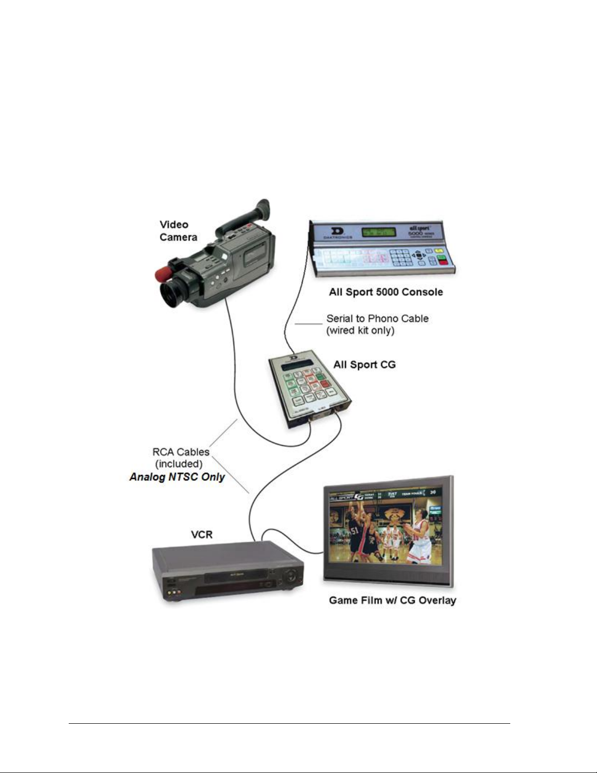
Figure 2: All Sport CG Typical System Layout
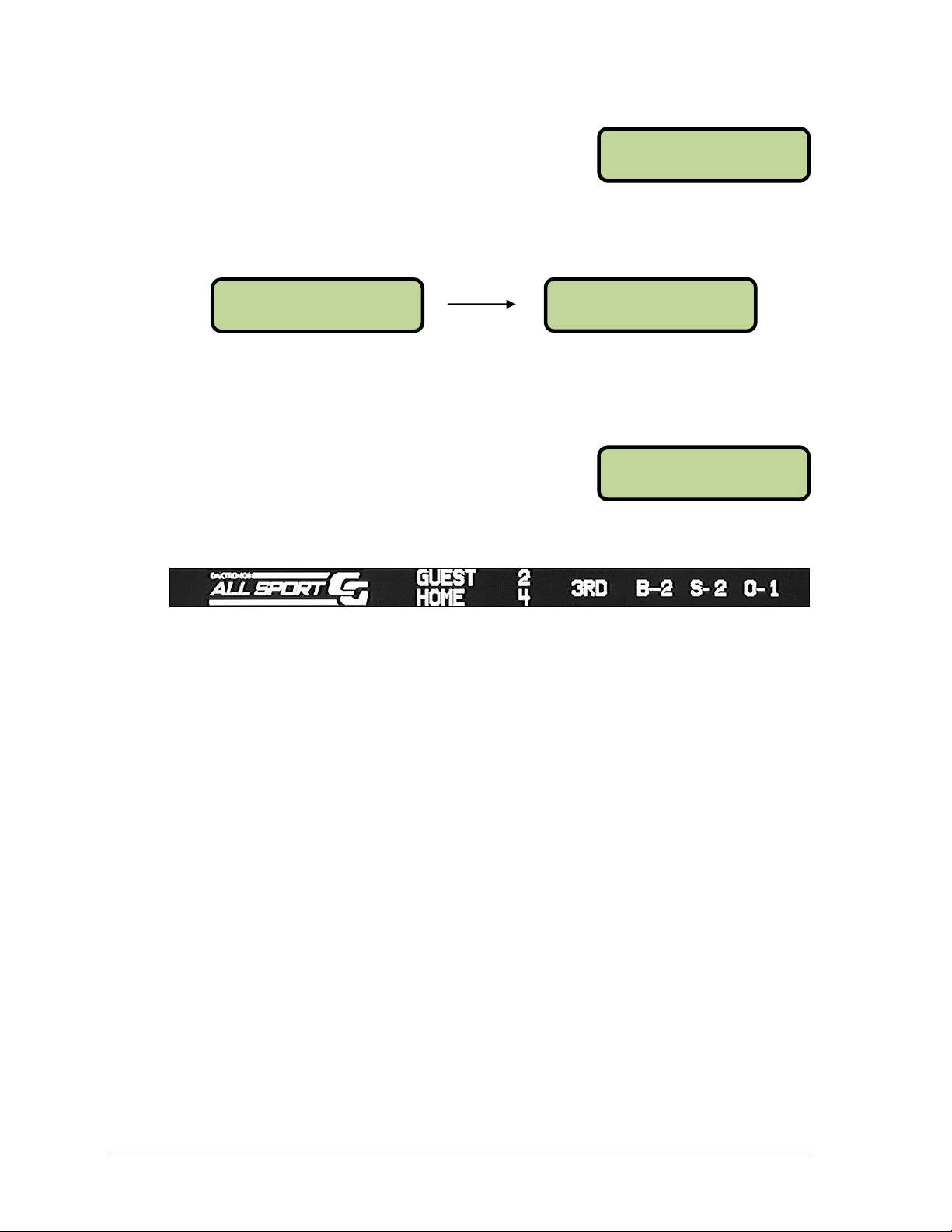
1.2 System Overview
The All Sport CG is an interface that receives footage from a video camera and overlays
game-in-progress (GIP) data from an All Sport controller onto the video footage. It then sends
the footage combined with the data to a video recording device. The result is game video
with scoring and timing information always shown with the footage (Figure 2).
The connection between the All Sport controller and the All Sport CG can be either wire or
radio. The radio option allows for more flexibility and fewer physical connections (an All
Sport CG with the radio option can still use a wire connection as a backup if desired).
System Requirements
The All Sport CG system requires the following additional components (sold separately):
• Video camera
• Recording device, such as a VCR, DVD recorder, or video capture card
• All Sport 3000, 5000, or 5500 control console (optional, but recommended)
2 Introduction
Page 9
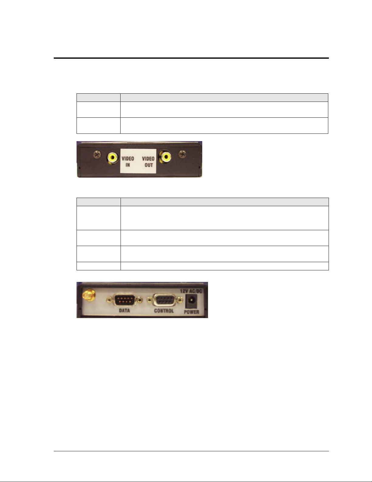
Jack
Description
VIDEO IN
(Composite)
Receives the video feed from camera or other source (analog NTSC Only)
VIDEO OUT
(Composite)
Sends the video feed with overlaid game-in-progress information to
recording device (analog NTSC Only)
Figure 3: All Sport CG, Bottom View
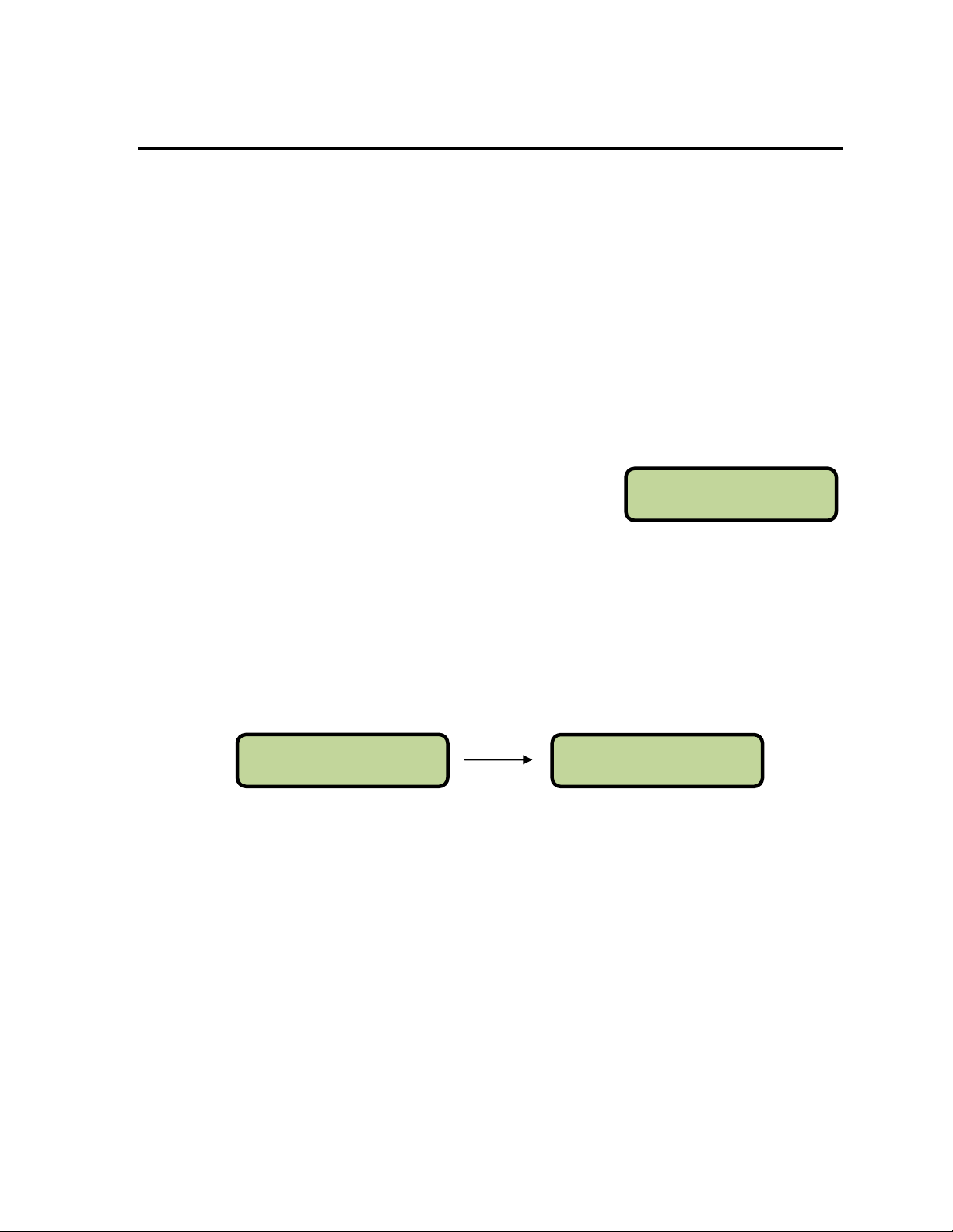
Jack
Description
Antenna
Radio Unit Only. Receives game-in-progress information from the All
Sport controller via wireless radio signal (both All Sport CG and control
console must be equipped with optional radio kits)
DATA
(DB9-M)
Receives the game-in-progress information from the All Sport controller
via a direct wire connection
CONTROL
(DB9-F)
Receives firmware upgrade information; also used to output TV data feeds
and upload custom graphics (see Appendix B)
POWER
Receives power via 12 VAC transformer
Figure 4: All Sport CG, Top View
Section 2: Setup
Use the tables and figures below to identify the various jacks that are used to connect
components to the All Sport CG:
2.1 Power Connection
The All Sport CG receives power from a standard 120 VAC outlet via a 12 VAC transformer
to the POWER jack on top of the All Sport CG. Plugging in and disconnecting the transformer
will power the unit on and off.
2.2 Video Camera Connection
The connection between the camera or video source and the All Sport CG is always via wire.
The analog NTSC video signal is carried via an RCA cable connection from the VIDEO OUT
jack on the video camera to the VIDEO IN jack on the bottom panel of the All Sport CG.
Setup 3
Page 10

BROADCAST GROUP
FO R RA DI O 0 *
CH ANN EL N UMB ER
FO R RA DI O 0 *
B= 0 S= 0 O= 0 R
G= 0 *H = 0 I = 1
B= 0 S= 0 O= 0 ?
G= 0 *H = 0 I = 1
2.3 Recording Device Connection
The connection between the recording device and All Sport CG is always via wire. An RCA
cable sends the combined data via a connection from the VIDEO OUT port on the bottom of
the All Sport CG to the VIDEO IN port on the VCR or other recording device.
2.4 All Sport Controller Connection
There are three ways to get scoring information into the All Sport CG (each method is also
detailed in Drawing A-240848 located in Appendix A):
• Wire connection between the All Sport CG and the All Sport controller
• Wireless radio signal between the All Sport CG and the All Sport controller
• All Sport CG used manually (no All Sport controller required)
Wire Connection
For a wire connection, game-in-progress data is sent through a cable from the ¼” phone jack
(J1, J2, or J3) on the back of the All Sport 3000, 5000, or 5500 series controller to the 9-pin
DATA port on top of the All Sport CG.
Wireless Radio Connection
When the wireless radio option is used, game-in-progress data is sent via radio signal from
the All Sport 3000, 5000, or 5500 series controller equipped with a radio transmitter to the All
Sport CG with a radio receiver. The radio signal has a communication distance of up to 500'
(152 m) indoor or 1500' (457 m) outdoor with a clear line of sight.
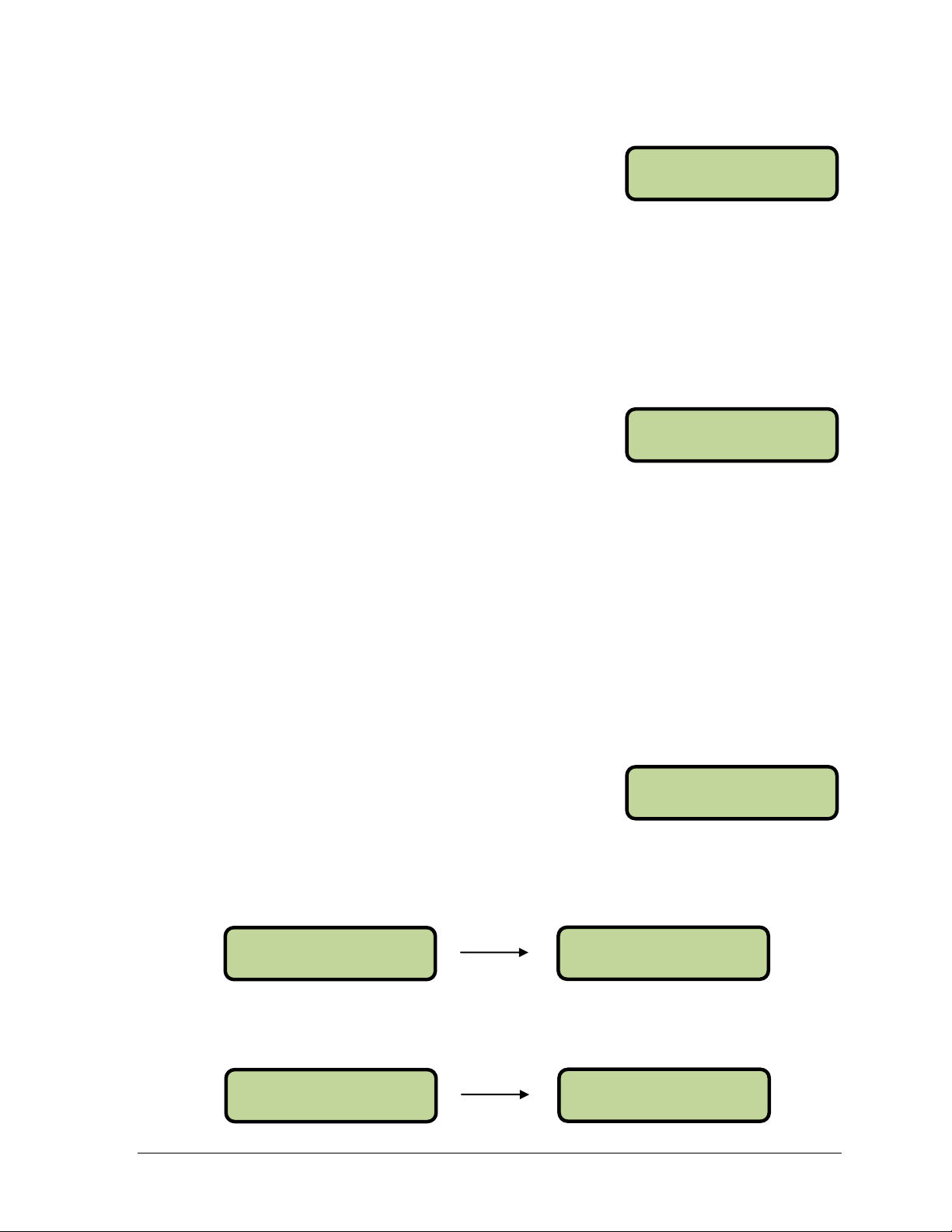
If an internal radio is detected when the All Sport CG is
turned on, the user will be prompted for a Broadcast
Group. Enter the corresponding Broadcast Group setting
from the All Sport controller and then press <ENTER */EDIT>.
Next, a prompt will appear to enter the Channel Number.
Enter the corresponding Channel Number setting from the
All Sport controller and then press <ENTER */EDIT>.
Refer to the appropriate All Sport controller operation manual (located online at
www.daktronics.com/manuals) for detailed instructions on selecting the proper Broadcast
Group and Channel Number being used to control the scoreboard.
Radio Connection Status
When a wireless All Sport CG is successfully connected to a
console via radio, an “R” displays in the upper-right corner
of the LCD. If a wireless All Sport CG cannot find a radio
with the specified Broadcast Group and Channel numbers,
a “?” is shown instead.
No All Sport Connection
If no All Sport controller is available for use with the All Sport CG, such as for a road game,
it’s possible to operate in Manual Mode. Refer to Section 3.3 for more information.
4 Setup
Page 11
NE W GA ME
EN TER TO M ODI F Y
HO ME T EAM NAM E
EN TER TO M ODI F Y
HO ME T EAM NAM E
_OME
Section 3: Operation
There are two primary modes in which the All Sport CG can operate:
• Automatic Mode: Game data is received from the All Sport controller using a wire connection
or wireless radio signal (refer to Section 2.4).
• Manual Mode: Game data is generated using the keypad, without using an All Sport controller.
Some of the menu options can be adjusted in both modes, while others are for Manual mode only.
3.1 Menu Options
• Press <MENU> to access the setup options.
• Use <↑> and <↓> to move between menu items.
• Press <MENU> again at any time to exit.
New Game
Press <ENTER */EDIT> to clear all of the current game
information.
Note: This action is only available in Manual mode and cannot be undone!
Guest & Home Team Name
To enter team names, use the Alpha-Numeric insert printed on the back of the sport insert.
Press <ENTER */EDIT> to modify the team name. The currently selected letter will flash.
Use the keypad to type in a name or abbreviation for the team (up to 10 characters). After
entering a team name, press <ENTER */EDIT> to save.
These menu items can be set in both Automatic and Manual modes.
Note: Team names must be configured on the All Sport CG when it is used in Manual
mode or with an All Sport 3000 series controller. The All Sport 5000 and 5500 controllers
can output team names as part of the data transferred to the All Sport CG.
Alpha-Numeric Keypad Insert
The All Sport CG has an alpha-numeric keypad insert used for entering team names (refer to
Drawing A-239213).
Entering words is identical to that of a touchtone phone, with no letters on key 1, and the rest
of the letters assigned in groups on keys 2-9. Press 0 to insert a space. When prompted to
enter text, the LCD will display a flashing cursor. Type in the name and press <ENTER
*/EDIT> to save the changes.
Operation 5
Page 12

SE LEC T SP ORT
EN TER TO M ODI FY
SE LEC T MO DE
EN TER TO M ODI F Y
SE LEC T I NP UT
EN TER TO M ODI F Y
Other helpful hints:
1. If a key is pressed too many times and a character is missed, simply keep pressing the
key until it appears again.
2. If an error is made when entering a character, press <CLEAR> or use <↑> to go back
to the previous character.
3. Pressing a different key for one of the other characters will immediately start entry at
the next location.
4. To avoid waiting for the character to quit flashing to enter another from the same
key, press <↓> to immediately move to the next location.
5. To edit a specific character, use <↑> and <↓> to move back and forth.
Select Sport
When using the All Sport CG in Manual mode, the current
sport needs to be selected. Press <ENTER */EDIT> and
press <↑> and <↓> to toggle between the available sports.
Press <ENTER */EDIT> again to select a sport.
Note: The sport can only be selected in Manual mode. When connected to an All Sport
controller, the sport is selected automatically (if it can be detected).
Select Mode
Press <ENTER */EDIT> and then press <↑> and <↓> to
toggle between MANUAL and AUTOMATIC modes. Press
<ENTER */EDIT> again to select a mode.
On power up, the All Sport CG will set the mode to Automatic if an All Sport controller is
detected and the sport can be determined.
If the setup contains an All Sport controller, the mode needs to be set to Automatic in order to
receive game data from the control console. When the All Sport CG is set to Automatic, the
output data cannot be changed by using the keypad.
The mode needs to be set to Manual in order to operate the All Sport CG when a control
console is not available. Also, the mode can be switched to Manual at any time to override
and ignore the data from a connected controller.
Select Input
Press <ENTER */EDIT> and then press <↑> and <↓> to
toggle between WIRE and RADIO inputs. Press <ENTER
*/EDIT> again to select an input type.
On power up, the All Sport CG will set the Input to the source that first detects an All Sport.
Note: This menu item is only available for editing when the All Sport CG is in Automatic
mode and an internal radio is detected.
6 Operation
Page 13
OV ERL AY L OCA TI ON
EN TER TO M ODI F Y
LO OKI N G FO R
AL L SP ORT
TE AM S COR E: + 1
HO ME 7
TI M E 8: 00
SE LEC T AL T I TE M
TE AM S COR E: -1
HO ME 6
TI M E 8: 00
SE LEC T ED I T I TE M
TE AM S COR E: E DI T
HO ME ^ ^6*
Overlay Location
By default, scoring information from the All Sport CG is
displayed across the top of the video output. To change this
location, press <ENTER */EDIT> and press <↑> and <↓> to
toggle between Very Top, Top, Bottom, and Very Bottom.
Press <ENTER */EDIT> again to save.
3.2 Automatic Mode
Operation of the All Sport CG is simple when connected to an All Sport controller. The All
Sport CG receives game data via wire or wireless radio from the control console and overlays
it onto the video feed in real time. The All Sport CG is automatically set to the same sport as
the control console and all information is received directly from it.
When the All Sport CG is set to Automatic mode, it will
search for a signal from the All Sport controller. If the
controller is not connected, the LCD displays the message:
The only direct operation required is configuring the Broadcast Group and Channel Number
for use with a radio control console. Refer to Section 2.4 and the appropriate All Sport
controller operation manual for more information.
3.3 Manual Mode
When using Manual mode, the All Sport CG does not have an external source for game data,
so all information must be entered by hand with the keypad. The All Sport CG uses
removable inserts to denote which button has what function for the particular sport mode.
The buttons that apply to all sports include <MENU> and <↑> and <↓> navigation. Each
sport also has buttons with specific functions (described in the following sections).
Scoring
Each sport has two to six buttons on the keypad insert used
for keeping score. Press these buttons to increment, or add
to, the score by the value printed on the insert.
To decrement, or subtract, points from the home team, press <CLEAR/ALT> then <HOME
SCORE +1/-1>. To decrement points from the guest team, press <CLEAR/ALT> then
<GUEST SCORE +1/-1>. Only one point can be subtracted from either team at a time.
The score can also be edited by pressing <ENTER*/EDIT> followed by any of the scoring
buttons. Use the keypad to type in the value, and then press <ENTER*/EDIT> again to save.
Operation 7
Page 14
TI M E ED I T SE T
CU RR ^ 8:0 0*
TI M E 8: 00
SE LEC T AL T I TE M
MA I N CL OCK -DOWN
1- UP 2 -DOWN
B= 0 S= 0 O= 0
*G = 0 H = 0 I = 1
Timing
Every sport but baseball and tennis has a timing function.
Press <SET TIME*> and use the keypad to type in the
value. Press <ENTER*/EDIT> again to save.
The clock can also be set to count up or count down (default). Press <CLEAR/ALT> followed
by <SET TIME*>, and then press <1> to count up or <2> to count down.
To start the clock, press <START/↑>.
To stop the clock, press <STOP/↓>.
Baseball
The following buttons and functions are unique to the
baseball sport mode. Refer to Drawing A-1022172 to view
the baseball insert for the keypad.
Baseball Scoring Output:
Ball
• Press <BALL +1/-1> to increment the ball number.
• Press <CLEAR/ALT> followed by <BALL +1/-1> to decrement the ball number.
• Press <ENTER*/EDIT> followed by <BALL +1/-1> to edit the ball number.
Use the keypad to type in the value, and then press <ENTER*/EDIT> again to save.
• Press <CLEAR BALL & STRIKE> to remove all ball (and strike) information.
Strike
• Press <STRIKE +1/-1> to increment the strike number.
• Press <CLEAR/ALT> followed by <STRIKE +1/-1> to decrement the strike number.
• Press <ENTER*/EDIT> followed by <STRIKE +1/-1> to edit the strike number.
Use the keypad to type in the value, and then press <ENTER*/EDIT> again to save.
• Press <CLEAR BALL & STRIKE> to remove all strike (and ball) information.
Out
• Press <OUT +1/-1> to increment the out number.
• Press <CLEAR/ALT> followed by <OUT +1/-1> to decrement the out number.
• Press <ENTER*/EDIT> followed by <OUT +1/-1> to edit the number of outs.
Use the keypad to type in the value, and then press <ENTER*/EDIT> again to save.
8 Operation
Page 15

HO ME A T BA T
B= 0 S= 0 O= 0
G= 0 *H = 0 I = 1
BA TTE R ED I T
^^*
ER ROR ON
PO SI TI O N ^^ *
Runs
• Press <GUEST RUNS +1/-1> or <HOME RUNS +1/-1> to increment the number of
runs for the respective team.
• Press <CLEAR/ALT> followed by <GUEST RUNS +1/-1> or <HOME RUNS +1/-1>
to decrement the number of runs for the respective team.
• Press <ENTER*/EDIT> followed by <GUEST RUNS +1/-1> or <HOME RUNS +1/-1>
to edit the number of runs for the respective team. Use the keypad to type in the value,
and then press <ENTER*/EDIT> again to save.
Inning
• Press <INNING +1/-1> to increment the inning number.
• Press <CLEAR/ALT> followed by <INNING +1/-1> to decrement the inning
number.
• Press <ENTER*/EDIT> followed by <INNING +1/-1> to edit the inning number. Use
the keypad to type in the value, and then press <ENTER*/EDIT> again to save.
At Bat
• Press <AT BAT> to toggle between GUEST AT BAT and HOME AT BAT.
The current team up to bat will have an asterisk (*).
Batter Number
• Press <BATTER NUMBER> to edit the current
batter. Use the keypad to type in the player’s jersey
number, and then press <ENTER*/EDIT> to save.
Hit
• Press <HIT> to toggle between HIT ON and HIT OFF.
• Press <CLEAR HIT & ERROR> to remove all hit (and error) information.
Error
• Press <ERROR> to indicate an error. Use the
keypad to type in the player’s position number,
and then press <ENTER*/EDIT> to save.
• Press <CLEAR HIT & ERROR> to remove all
error (and hit) information.
• Press <ERROR> again to toggle errors OFF.
Operation 9
Page 16

TI M E 8: 00
H= 0 G= 0 P1
CLEAR T EAM FOU LS
EN TER TO C ONF I RM
TI M E 12 :00
H= 0 G= 0 Q1
BA LL O N: E DI T
^^*
Basketball
The following buttons and functions are unique to the
basketball sport mode. Refer to Drawing A-1020946 to view
the basketball insert for the keypad.
Basketball Scoring Output:
Team Fouls
• Press <HOME FOULS +1/-1> or <GUEST FOULS +1/-1> to increment the number of
team fouls for the respective team.
• Press <CLEAR/ALT> followed by <HOME FOULS +1/-1> or <GUEST FOULS +1/-1>
to decrement the number of team fouls for the respective team.
• Press <ENTER*/EDIT> followed by <HOME FOULS +1/-1> or <GUEST FOULS +1/-1>
to edit the number of team fouls for the respective team. Use the keypad to type in the
value, and then press <ENTER*/EDIT> again to save.
• Press <CLEAR TEAM FOULS> followed by
<ENTER*/EDIT> to remove all team foul
information for both the home and guest teams.
Period
• Press <PERIOD +1/-1> to increment the period number.
• Press <CLEAR/ALT> followed by <PERIOD +1/-1> to decrement the period number.
• Press <ENTER*/EDIT> followed by <PERIOD +1/-1> to edit the period number.
Use the keypad to type in the value, and then press <ENTER*/EDIT> again to save.
Football
The following buttons and functions are unique to the
football sport mode. Refer to Drawing A-1022204 to view
the football insert for the keypad.
Football Scoring Output:
Ball On
• Press <BALL ON*> to set the current yard line of
the ball. Use the keypad to type in the value, and
then press <ENTER*/EDIT> to save.
Down
• Press <DOWN +1/-1> to increment the down number.
• Press <CLEAR/ALT> followed by <DOWN +1/-1> to decrement the down number.
• Press <ENTER*/EDIT> followed by <DOWN +1/-1> to edit the down number.
Use the keypad to type in the value, and then press <ENTER*/EDIT> again to save.
10 Operation
Page 17

TO GO: EDI T
^^*
TI M E 15 :00
H= 0 G= 0 P=1
Yards To Go
• Press <YARDS TO GO*> to edit the number of
yards for a first down. Use the keypad to type in
the value, and then press <ENTER*/EDIT> to save.
Possession
• Press <CLEAR/ALT> followed by <HOME SCORE +6/POSS> or <GUEST SCORE
+6/POSS> to set the possession for the respective team. Press one of these button
combinations again to remove the possession for the respective team.
Quarter
• Press <QUARTER +1/-1> to increment the quarter number.
• Press <CLEAR/ALT> followed by <QUARTER +1/-1> to decrement the quarter number.
• Press <ENTER*/EDIT> followed by <QUARTER +1/-1> to edit the quarter number.
Use the keypad to type in the value, and then press <ENTER*/EDIT> again to save.
Hockey/Lacrosse/Field Hockey
The following buttons and functions are unique to the
hockey sport mode. This mode may also be used for scoring
lacrosse and field hockey. Refer to Drawing A-1022210 to
view the hockey insert for the keypad.
Hockey Scoring Output:
Shots on Goal
• Press either home or guest <SHOTS ON GOAL +1/-1> to increment the number of
shots on goal for the respective team.
• Press <CLEAR/ALT> followed by either home or guest <SHOTS ON GOAL +1/-1>
to decrement the number of shots on goal for the respective team.
• Press <ENTER*/EDIT> followed by either home or guest <SHOTS ON GOAL +1/-1>
to edit the number of shots on goal for the respective team. Use the keypad to type in
the value, and then press <ENTER*/EDIT> again to save.
Period
• Press <PERIOD +1/-1> to increment the period number.
• Press <CLEAR/ALT> followed by <PERIOD +1/-1> to decrement the period number.
• Press <ENTER*/EDIT> followed by <PERIOD +1/-1> to edit the period number.
Use the keypad to type in the value, and then press <ENTER*/EDIT> again to save.
Operation 11
Page 18

TI M E 45 :00
H= 0 G= 0 H1
TO P= 0 0
BO T= 0 0 C1
TO P SE RVE
ON
Soccer
The following buttons and functions are unique to the
soccer sport mode. Refer to Drawing A-1022208 to view the
soccer insert for the keypad.
Soccer Scoring Output:
Shots on Goal
• Press either home or guest <SHOTS ON GOAL +1/-1> to increment the number of
shots on goal for the respective team.
• Press <CLEAR/ALT> followed by either home or guest <SHOTS ON GOAL +1/-1>
to decrement the number of shots on goal for the respective team.
• Press <ENTER*/EDIT> followed by either home or guest <SHOTS ON GOAL +1/-1>
to edit the number of shots on goal for the respective team. Use the keypad to type in
the value, and then press <ENTER*/EDIT> again to save.
Half
• Press <HALF +1/-1> to increment the half number.
• Press <CLEAR/ALT> followed by <HALF +1/-1> to decrement the half number.
• Press <ENTER*/EDIT> followed by <HALF +1/-1> to edit the half number. Use the
keypad to type in the value, and then press <ENTER*/EDIT> again to save.
Tennis
The following buttons and functions are unique to the
tennis sport mode. Refer to Drawing A-1022220 to view the
tennis insert for the keypad.
Tennis Scoring Output:
Serve
• Press <SERVE> in the appropriate TOP or
BOTTOM key group to turn the serve on or off.
Point
• Press <POINT/DEC> in the appropriate TOP or BOTTOM key group to increment
the number of points for the top or bottom.
• Press <CLEAR/ALT> followed by <POINT/DEC> in the appropriate TOP or
BOTTOM key group to decrement the number of points for the top or bottom.
• Press <ENTER*/EDIT> followed by <POINT/DEC> in the appropriate TOP or
BOTTOM key group to edit the number of points for the top or bottom. Use the
keypad to type in the value, and then press <ENTER*/EDIT> again to save.
12 Operation
Page 19

GA MES WON - +1
SE T 1 T OP 1
RE SET GAM E
EN TER TO C ONF I RM
TO P=1 5 2
SE LEC T AL T I TE M
RE SET MAT CH
EN TER TO C ONF I RM
SE LEC T CO URT
EN TER TO M ODI F Y
Games Won
• Press <GAMES WON +1/-1> in the appropriate
TOP or BOTTOM key group to increment the
number of games won for the top or bottom.
• Press <CLEAR/ALT> followed by <GAMES WON +1/-1> in the appropriate TOP or
BOTTOM key group to decrement the number of games won for the
top or bottom.
• Press <ENTER*/EDIT> followed by <GAMES WON +1/-1> in the appropriate TOP
or BOTTOM key group to edit the number of games won for the top or bottom. Use
the keypad to type in the value, and then press <ENTER*/EDIT> again to save.
Reset Game
• Press <RESET GAME/MATCH> followed by
<ENTER*/EDIT> to reset the scores for both sides
in the current set.
Reset Match
• Press <CLEAR/ALT> followed by <RESET GAME/MATCH > followed by
<ENTER*/EDIT> to reset the scores and sets for both sides in the current match.
Tie Break
• Press <TIE BREAK> to enter the tie break mode. This mode allows for entering
individual points one at a time.
• Use the Reset Game function to return to normal operation.
Deuce
• Press <DUECE> to quickly set both top and bottom point values to 40.
Set
• Press <SET +1/-1> to increment the set number.
• Press <CLEAR/ALT> followed by <SET +1/-1> to decrement the set number.
• Press <ENTER*/EDIT> followed by <SET +1/-1> to edit the set number. Use the
keypad to type in the value, and then press <ENTER*/EDIT> again to save.
Note: The LCD shows the games won for up to 3 sets, but the All Sport CG is capable
of scoring 5 sets in a match. After 3 sets, the current set number is visible only when
adjusting the games won.
Select Court
When connected to DakTennis software, press <MENU> to
access the Select Court setting. Use the keypad to type in
the desired court number from 1 to 12, and then press
<ENTER*/EDIT> to save. The court number is displayed
in the lower-right corner of the LCD.
Operation 13
Page 20

TI M E 1: 00
H= 0 G= 0 S1
HO ME S ERV E
ON
SE TS W ON: +1
HO ME 1
TI M E 2: 00
H= 0 G= 0 P1
Volleyball
The following buttons and functions are unique to the
volleyball sport mode. Refer to Drawing A-1022216 to view
the volleyball insert for the keypad.
Volleyball Scoring Output:
Home/Guest Serve
• Press <SERVE> under the appropriate team to turn
the serve on or off.
Sets Won
• Press <SETS WON +1/-1> under the appropriate
team to increment the number of sets won.
• Press <CLEAR/ALT> followed by <SETS WON
+1/-1> under the appropriate team to decrement the number of sets won.
• Press <ENTER*/EDIT> followed by < SETS WON +1/-1> under the appropriate
team to edit the number of sets won. Use the keypad to type in the value, and then
press <ENTER*/EDIT> again to save.
Set
• Press <SET +1/-1> to increment the set number.
• Press <CLEAR/ALT> followed by <SET +1/-1> to decrement the set number.
• Press <ENTER*/EDIT> followed by <SET +1/-1> to edit the set number. Use the
keypad to type in the value, and then press <ENTER*/EDIT> again to save.
Wrestling
The following buttons and functions are unique to the
wrestling sport mode. Refer to Drawing A-1022218 to view
the wrestling insert for the keypad.
Wrestling Scoring Output:
Team Score
• Press <HOME TEAM +1/-1> or <GUEST TEAM +1/-1> to increment the team score
for the respective team.
• Press <CLEAR/ALT> followed by <HOME TEAM +1/-1> or <GUEST TEAM +1/-1>
to decrement the team score for the respective team.
• Press <ENTER*/EDIT> followed by <HOME TEAM +1/-1> or <GUEST TEAM +1/-1>
to edit the team score for the respective team. Use the keypad to type in the value, and
then press <ENTER*/EDIT> again to save.
14 Operation
Page 21

Match Score
• Press <HOME MATCH +1/-1> or <GUEST MATCH +1/-1> to increment the match
score for the respective team by 1.
• Press <HOME MATCH +2/+3> or <GUEST MATCH +2/+3> to increment the match
score for the respective team by 2.
• Press <CLEAR/ALT> followed by <HOME MATCH +2/+3> or <GUEST MATCH
+2/ +3> to increment the match score for the respective team by 3.
• Press <CLEAR/ALT> followed by <HOME MATCH +1/-1> or <GUEST MATCH
+1/-1> to decrement the match score for the respective team.
• Press <ENTER*/EDIT> followed by any <MATCH> key to edit the match score for
the respective team. Use the keypad to type in the value, and then press
<ENTER*/EDIT> again to save.
Period
• Press <PERIOD +1/-1> to increment the period number.
• Press <CLEAR/ALT> followed by <PERIOD +1/-1> to decrement the period number.
• Press <ENTER*/EDIT> followed by <PERIOD +1/-1> to edit the period number.
Use the keypad to type in the value, and then press <ENTER*/EDIT> again to save.
Operation 15
Page 22

Page 23

Problem
Possible Solution
All Sport CG does not turn on
Ensure the transformer is plugged into the wall
outlet and connected to the All Sport CG
Ensure the wall outlet has power (breaker not off)
Video feed does not show on
the output
Check the connection between the video source and
the All Sport CG
Check the connection between the All Sport CG and
the recording device
Ensure the video equipment is ON and working.
Refer to the video equipment user’s manual for
further troubleshooting.
Video does not record
Ensure the recording device is ON and working.
Refer to the recording device user’s manual for
further troubleshooting.
Ensure that the video media is not copy protected.
Game-in-progress information
does not show on the output
Check the wired or wireless connection between the
All Sport controller and the All Sport CG if in
Automatic mode.
Ensure the All Sport CG is set to a sport whether in
Manual or Automatic mode.
Ensure the All Sport controller is ON and a code
number has been entered.
Part Description
Part Number
All Sport CG Inserts
LL-2612
Cable; 20', 9 pin-D-Female to ¼" Phono
0A-1196-0146
Cable, RCA Male-to-Male, 6'
W-1219
Transformer; 12 VAC
T-1118
Section 4: Troubleshooting
The Daktronics All Sport CG connects a control console and video equipment with a device used to
record and display the information. To do this properly, the devices must be connected correctly.
A combination TV/VCR works well as a recording device because it allows the operator to view the
final output as it is recorded. By seeing the output on screen, the operator knows instantly if there is
not a proper connection and what part of the system is not working.
Use the following suggestions to troubleshoot some of the more common problems that may occur
with the All Sport CG system:
4.1 Replacement Parts
Troubleshooting 17
Page 24

Market Description
Customer Service Number
Schools (including community/junior colleges), religious
organizations, municipal clubs and community centers
877-605-1115
Universities and professional sporting events, live events
for auditoriums and arenas
866-343-6018
4.2 Daktronics Exchange and Repair & Return Programs
Exchange Program
The Daktronics Exchange Program is a service for quickly replacing key components in need
of repair. If a component fails, Daktronics sends a replacement part to the customer who, in
turn, returns the failed component to Daktronics. This decreases equipment downtime.
Customers who follow the program guidelines explained below will receive this service.
Before Contacting Daktronics
Identify these important numbers:
Assembly Number: ____________________________________________________________
Job/Contract Number:__________________________________________________________
Date Installed: _________________________________________________________________
Daktronics Customer ID Number: ________________________________________________
To participate in the Exchange Program, follow these steps.
1. Call Daktronics Customer Service.
2. If the replacement part fixes the problem, send in the problem part being replaced.
a. Package the old part in the same shipping materials in which the replacement
part arrived.
b. Fill out and attach the enclosed UPS shipping document.
c. Ship the part to Daktronics.
3. The defective or unused parts must be returned to Daktronics within 5 weeks of
initial order shipment.
If any part is not returned within five (5) weeks, a non-refundable invoice will be
presented to the customer for the costs of replenishing the exchange parts inventory
with a new part.
Daktronics reserves the right to refuse parts that have been damaged due to acts of
nature or causes other than normal wear and tear.
18 Troubleshooting
Page 25

Repair & Return Program
For items not subject to exchange, Daktronics offers a Repair & Return Program. To send a
part for repair, follow these steps:
1. Call or fax Daktronics Customer Service:
Refer to the appropriate market number in the chart listed on the previous page.
Fax: 605-697-4444
2. Receive a case number before shipping.
This expedites repair of the part.
3. Package and pad the item carefully to prevent damage during shipment.
Electronic components, such as printed circuit boards, should be placed in an
antistatic bag before boxing. Daktronics does not recommend using packing ‘peanuts’
when shipping.
4. Enclose:
name
address
phone number
the case number
a clear description of symptoms
Shipping Address
Daktronics Customer Service
[Case #]
201 Daktronics Drive, Dock E
Brookings, SD 57006
Daktronics Warranty and Limitation of Liability
The Daktronics Warranty and Limitation of Liability is located in Appendix C. The Warranty
is independent of Extended Service agreements and is the authority in matters of service,
repair, and display operation.
Troubleshooting 19
Page 26

Page 27

Appendix A: Reference Drawings
Drawing Title Drawing Number
Insert; LL-2612 All Sport CG, Alpha Numeric .......................................................................... A-239213
Quick Install Guide; All Sport CG ............................................................................................. A-240848
Insert; LL-2612 A/S CG, Basketball ........................................................................................ A-1020946
Insert; LL-2612 A/S CG, Baseball ........................................................................................... A-1022172
Insert; LL-2612 A/S CG, Football ............................................................................................ A-1022204
Insert; LL-2612 A/S CG, Soccer ............................................................................................. A-1022208
Insert; LL-2612 A/S CG, Hockey ............................................................................................ A-1022210
Insert; LL-2612 A/S CG, Volleyball ......................................................................................... A-1022216
Insert; LL-2612 A/S CG, Wrestling ......................................................................................... A-1022218
Insert; LL-2612 A/S CG, Tennis .............................................................................................. A-1022220
Reference Drawings 21
Page 28

Page 29

Page 30

Page 31

0
7
1 2
3
1
ALL SPORT CG
5
64
8 9
LL-2612
BASKETBALL
Page 32

0
7 8 9
64
1 2 3
5
1
ALL SPORT CG BASEBALL
LL-2612
Page 33

0
4
1 2
3
1
ALL SPORT CG
6
5
8 97
LL-2612
FOOTBALL
Page 34

0
4
1 2
3
1
ALL SPORT CG
6
5
8 97
LL-2612
SOCCER
Page 35

0
4
1 2
3
1
ALL SPORT CG
6
5
8 97
LL-2612
HOCKEY
Page 36

0
7
1 2
3
1
ALL SPORT CG
5
4
8 9
6
LL-2612
VOLLEYBALL
Page 37

0
8
ALL SPORT CG
5
1
3
64
7 9
2
LL-2612
WRESTLING
Page 38

0
7 8 9
4
11
ALL SPORT CG
2
3
5
6
LL-2612
TENNIS
Page 39

Figure 5: Acceptable Bitmap Parameters
Figure 6: HyperTerminal COM Port Properties
Appendix B: Uploading Bitmaps to All Sport CG
Requirements
• All Sport CG and 12 VAC transformer
• Computer loaded with HyperTerminal,
TeraTerm, or similar application
• One serial (COM) port
• Serial cable with DB9 female to DB9 male
(modem or straight-through cable)
• Bitmap File (.bmp) created using the
parameters shown in Figure 5.
o Go to Start > All Programs >
Accessories > Paint.
o Go to Image > Attributes (or Paint
button > Properties in Windows 7).
o Save the file as 24-bit Bitmap.
HyperTerminal Procedure (Windows XP)
1. Connect the serial cable from a COM port on
the computer to the CONTROL port on the
All Sport CG.
2. Apply power to the All Sport CG using the
12 VAC transformer supplied and wait for
LOOKING FOR ALL SPORT to appear on
the LCD.
3. Go to Start > All Programs > Accessories >
Communications > HyperTerminal.
4. Enter a Name in the Connection Description
window and then click OK.
5. On the Connect To window, select the COM
port connected to the All Sport CG and then
click OK.
6. On the Port Settings tab in the COMx
Properties window, enter the settings as
shown in Figure 6 and then click OK.
7. Press [Enter] on the keyboard to confirm that
the COM port has been configured properly and that the serial cable is correctly
connected. The message “AllSportCG>” will appear in the HyperTerminal application if
proper communication has been established.
8. Type in “BD” and press [Enter]. The message “Transfer file now” will appear.
9. Go to Transfer > Send File.
10. In the Send File window, click Browse and navigate to the bitmap image file created with
the parameters shown in Figure 5, select Xmodem as the Protocol, and click Send to
initiate the file transfer.
11. After a few seconds, the Transfer window will close and the All Sport CG will be loaded
with the new bitmap file.
12. Disconnect the serial cable from the All Sport CG and CYCLE POWER to return the
device to normal operation and begin displaying the new graphic.
Uploading Bitmap Files to All Sport CG 23
Page 40

Figure 7: TeraTerm Serial Port Setup
TeraTerm Procedure (Windows 7)
1.
Connect the serial cable from a COM port on the computer to the CONTROL port on
the All Sport CG.
2.
Apply power to the All Sport CG using the 12 VAC transformer supplied and wait
LOOKING FOR ALL SPORT
for
3.
Open TeraTerm, and go to
4.
Set up the port as shown below and
Port:
a.
the serial (COM) port
to appear on the LCD.
Setup
Serial Port Setup
>
Figure 7
.
:
that the All Sport CG is
connected to
Baud rate:
b.
Data:
c.
Parity:
d.
e.
Stop:
Flow control:
f.
Transmit delay:
g.
h.
Click OK when finished.
8 bit
none
1 bit
115200
none
0, 0
5.
[Enter]
Press
“
Unknown command” appears
on the keyboard.
with “AllSportCG>” underneath
to indicate proper connection of
the computer and All Sport CG.
6.
Type in “BD” and press
7.
8.
9.
File > Transfer > XModem > Send
Go to
Navigate to the bitmap image file created with the parameters shown in
Open
click
.
Once the progress bar is complete, press
[Enter]
. The message “Transfer file now” will appear.
.
Figure 5
[Enter]
on the keyboard. “AllSportCG>”
and
appears again to indicate the file transfer is complete.
10.
Disconnect the serial cable from the All Sport CG and
CYCLE POWER
to return the
device to normal operation and begin displaying the new graphic.
24 Uploading Bitmap Files to All Sport CG
Page 41

Appendix C: Daktronics Warranty and Limitation
of Liability
Daktronics Warranty and Limitation of Liability 25
Page 42

Page 43

Copyright © Daktronics, Inc. SL-02374 Rev 10 02-Mar-2009 Page 1 of 2
DAKTRONICS
WARRANTY AND LIMITATION OF LIABILITY
This Warranty and Limitation of Liability (the “Warranty”) sets forth the warranty provided by Daktronics with respect to the Equipment. By
accepting delivery of the Equipment, Purchaser agrees to be bound by and accept these terms and conditions. All defined terms within
the Warranty shall have the same meaning and definition as provided elsewhere in the Agreement.
DAKTRONICS WILL ONLY BE OBLIGATED TO HONOR THE WARRANTY SET FORTH IN THESE TERMS AND CONDITIONS UPON RECEIPT OF FULL
PAYMENT FOR THE EQUIPMENT.
1. Warranty Coverage
2. Exclusion from Warranty Coverage
A. Daktronics warrants to the original end-user that the Equipment will be free from Defects (as defined below) in materials and
workmanship for a period of one (1) year (the “Warranty Period”). The warranty period shall commence on the earlier of: (i) four
weeks from the date that the equipment leaves Daktronics’ facility; or (ii) Substantial Completion as defined herein. The warranty
period shall expire on the first anniversary of the commencement date.
“Substantial Completion” means the operational availability of the Equipment to the Purchaser in accordance with the
Equipment’s specifications, without regard to punch-list items, or other non-substantial items which do not affect the operation of
the Equipment.
B. Daktronics’ obligation under this Warranty is limited to, at Daktronics’ option, replacing or repairing, any Equipment or part
thereof that is found by Daktronics not to conform to the Equipment’s specifications. Unless otherwise directed by Daktronics,
any defective part or component shall be returned to Daktronics for repair or replacement. Daktronics may, at its option,
provide on-site warranty service. Daktronics shall have a reasonable period of time to make such replacements or repairs and
all labor associated therewith shall be performed during regular working hours. Regular working hours are Monday through
Friday between 8:00 a.m. and 5:00 p.m. at the location where labor is performed, excluding any holidays observed by either
Purchaser or Daktronics.
C. Daktronics shall pay ground transportation charges for the return of any defective component of the Equipment. If returned
Equipment is repaired or replaced under the terms of this warranty, Daktronics will prepay ground transportation charges back to
Purchaser; otherwise, Purchaser shall pay transportation charges to return the Equipment back to the Purchaser. All returns must
be pre-approved by Daktronics before shipment. Daktronics shall not be obligated to pay freight for any unapproved return.
Purchaser shall pay any upgraded or expedited transportation charges.
D. Any replacement parts or Equipment will be new or serviceably used, comparable in function and performance to the
original part or Equipment, and warranted for the remainder of the Warranty Period. Purchasing additional parts or Equipment
from the Seller does not extend this Warranty Period.
E. Defects shall be defined as follows. With regard to the Equipment (excepting LEDs), a “Defect” shall refer to a material
variance from the design specifications that prohibit the Equipment from operating for its intended use. With respect to LEDs,
“Defects” are defined as LED pixels that cease to emit light. The limited warranty provided by Daktronics does not impose any
duty or liability upon Daktronics for partial LED pixel degradation. Nor does the limited warranty provide for the replacement or
installation of communication methods including but not limited to, wire, fiber optic cable, conduit, trenching, or for the purpose
of overcoming local site interference radio equipment substitutions.
THIS LIMITED WARRANTY IS THE ONLY WARRANTY APPLICABLE TO THE EQUIPMENT AND REPLACES ALL OTHER WARRANTIES OR
CONDITIONS, EXPRESS OR IMPLIED, INCLUDING, BUT NOT LIMITED TO, THE IMPLIED WARRANTIES OR CONDITIONS OF
MERCHANTABILITY AND FITNESS FOR A PARTICULAR PURPOSE. SPECIFICALLY, EXCEPT AS PROVIDED HEREIN, THE SELLER
UNDERTAKES NO RESPONSIBILITY FOR THE QUALITY OF THE EQUIPMENT OR THAT THE EQUIPMENT WILL BE FIT FOR ANY PARTICULAR
PURPOSE FOR WHICH PURCHASER MAY BE BUYING THE EQUIPMENT. ANY IMPLIED WARRANTY IS LIMITED IN DURATION TO THE
WARRANTY PERIOD. NO ORAL OR WRITTEN INFORMATION, OR ADVICE GIVEN BY THE COMPANY, ITS AGENTS OR EMPLOYEES,
SHALL CREATE A WARRANTY OR IN ANY WAY INCREASE THE SCOPE OF THIS LIMITED WARRANTY.
THIS LIMITED WARRANTY IS NOT TRANSFERABLE.
The limited warranty provided by Daktronics does not impose any duty or liability upon Daktronics for:
A Any damage occurring, at any time, during shipment of Equipment unless otherwise provided for in the Agreement. When
returning Equipment to Daktronics for repair or replacement, Purchaser assumes all risk of loss or damage, and agrees to use
any shipping containers that might be provided by Daktronics and to ship the Equipment in the manner prescribed by
Daktronics;
B. Any damage caused by the unauthorized adjustment, repair or service of the Equipment by anyone other than personnel of
Daktronics or its authorized repair agents;
Page 44

Copyright © Daktronics, Inc. SL-02374 Rev 10 02-Mar-2009 Page 2 of 2
C. Damage caused by the failure to provide a continuously suitable environment, including, but not limited to: (i) neglect or
misuse, (ii) a failure or sudden surge of electrical power, (iii) improper air conditioning or humidity control, or (iv) any other cause
other than ordinary use;
D. Damage caused by fire, flood, earthquake, water, wind, lightning or other natural disaster, strike, inability to obtain materials
or utilities, war, terrorism, civil disturbance or any other cause beyond Daktronics’ reasonable control;
E. Failure to adjust, repair or replace any item of Equipment if it would be impractical for Daktronics personnel to do so because
of connection of the Equipment by mechanical or electrical means to another device not supplied by Daktronics, or the
existence of general environmental conditions at the site that pose a danger to Daktronics personnel;
F. Any statements made about the product by salesmen, dealers, distributors or agents, unless such statements are in a written
document signed by an officer of Daktronics. Such statements as are not included in a signed writing do not constitute
warranties, shall not be relied upon by Purchaser and are not part of the contract of sale;
G. Any damage arising from the use of Daktronics products in any application other than the commercial and industrial
applications for which they are intended, unless, upon request, such use is specifically approved in writing by Daktronics; or
H. Any performance of preventive maintenance.
3. Limitation of Liability
4. Assignment of Rights
5. Dispute Resolution
6. Governing Law
7. Availability of Extended Service Agreement
Daktronics shall be under no obligation to furnish continued service under this Warranty if alterations are made to the Equipment
without the prior written approval of Daktronics.
It is specifically agreed that the price of the Equipment is based upon the following limitation of liability. In no event shall
Daktronics (including its subsidiaries, affiliates, officers, directors, employees, or agents) be liable for any special, consequential,
incidental or exemplary damages arising out of or in any way connected with the Equipment or otherwise, including but not
limited to damages for lost profits, cost of substitute or replacement equipment, down time, lost data, injury to property or any
damages or sums paid by Purchaser to third parties, even if Daktronics has been advised of the possibility of such damages. The
foregoing limitation of liability shall apply whether any claim is based upon principles of contract, tort or statutory duty, principles
of indemnity or contribution, or otherwise.
In no event shall Daktronics be liable to Purchaser or any other party for loss, damage, or injury of any kind or nature arising out of
or in connection with this Warranty in excess of the purchase price of the Equipment actually delivered to and paid for by the
Purchaser. The Purchaser’s remedy in any dispute under this Warranty shall be ultimately limited to the Purchase Price of the
Equipment to the extent the Purchase Price has been paid.
The Warranty contained herein extends only to the original end-user (which may be the Purchaser) of the Equipment and no
attempt to extend the Warranty to any subsequent user-transferee of the Equipment shall be valid or enforceable without the
express written consent of Daktronics.
Any dispute between the parties will be resolved exclusively and finally by arbitration administered by the American Arbitration
Association (“AAA”) and conducted under its rules, except as otherwise provided below. The arbitration will be conducted
before a single arbitrator. The arbitration shall be held in Brookings, South Dakota. Any decision rendered in such arbitration
proceedings will be final and binding on each of the parties, and judgment may be entered thereon in any court of competent
jurisdiction. This arbitration agreement is made pursuant to a transaction involving interstate commerce, and shall be governed
by the Federal Arbitration Act.
The rights and obligations of the parties under this warranty shall not be governed by the provisions of the United Nations
Convention on Contracts for the International Sales of Goods of 1980. Both parties consent to the application of the laws of the
State of South Dakota to govern, interpret, and enforce all of Purchaser and Daktronics rights, duties, and obligations arising
from, or relating in any manner to, the subject matter of this Warranty, without regard to conflict of law principles.
For Purchaser’s protection, in addition to that afforded by the warranties set forth herein, Purchaser may purchase extended
warranty services to cover the Equipment. The Extended Service Agreement, available from Daktronics, provides for electronic
parts repair and/or on-site labor for an extended period from the date of expiration of this warranty. Alternatively, an Extended
Service Agreement may be purchased in conjunction with this warranty for extended additional services. For further information,
contact Daktronics Customer Service at 1-800-DAKTRONics (1-800-325-8766).
 Loading...