

Page 1

All Sport® 100
Control Console
Operations Manual
ED-13432 Rev 3 – 10 October 2007
Page 2

ED13432
Product 1196
Rev 3 – 10 October 2007
DAKTRONICS, INC.
Copyright © 2003-07
All rights reserved. While every precaution has been taken in the preparation of this manual, the p ublisher
assumes no responsibility for errors or omissions. No part of this book covered by the copyrights hereon may be
reproduced or copied in any form or by any means – graphic, electron ic, or mechanical, including photocopying,
taping, or information storage and retrieval systems – without written permission of the publisher.
All-Sport® is a trademark of Daktronics, Inc
Page 3

Table of Contents
Section 1: Introduction....................................................................................................1
1.1 How To Use This Manual..........................................................................................................1
1.2 Daktronics Nomenclature..........................................................................................................3
Section 2: Controller Overview ......................................................................................5
2.1 All Sport 100 Overview.............................................................................................................5
2.2 Display Connection....................................................................................................................6
2.3 Replacement Parts List ..............................................................................................................6
2.4 Daktronics Exchange and Repair and Return Programs............................................................6
Exchange Program..............................................................................................................6
Before Contacting Daktronics ............................................................................................7
Repair & Return Program...................................................................................................8
Shipping Address................................................................................................................8
Section 3: Basic Operation.............................................................................................9
3.1 Console Operation..................................................................................................................... 9
3.2 All Sport® 100 Inserts and Codes ..............................................................................................9
3.3 Sport Insert Operation Concepts..............................................................................................10
3.4 Startup......................................................................................................................................10
3.5 Common Sport Keys................................................................................................................11
Start...................................................................................................................................11
Stop...................................................................................................................................11
Enter/Edit..........................................................................................................................11
Clear/Alt ...........................................................................................................................11
Set Time............................................................................................................................11
Count Up/Down................................................................................................................12
Auto Horn.........................................................................................................................12
Manual Horn.....................................................................................................................13
Dimming...........................................................................................................................13
Section 4: Clock/Score Operation................................................................................15
4.1 Clock Keys...............................................................................................................................15
Set Time............................................................................................................................15
Period +1...........................................................................................................................16
4.2 Score Keys...............................................................................................................................17
Home/Guest Score Keys...................................................................................................17
Bonus Keys....................................................................................................................... 17
Possession Key.................................................................................................................18
Table of Contents i
Page 4

Section 5: Segment Timer Operation...........................................................................19
5.1 Segment Timer Information.....................................................................................................19
5.2 Segment Timer Keys................................................................................................................20
Main Screen......................................................................................................................20
First/Last Segment............................................................................................................20
Segment Number/Time.....................................................................................................20
Set Program ......................................................................................................................21
Interval Time.....................................................................................................................21
Copy Range ......................................................................................................................22
Auto Stop..........................................................................................................................22
Warning Time...................................................................................................................22
Reset Current Segment .....................................................................................................23
Edit Current Segment........................................................................................................23
Reset to First Segment......................................................................................................23
TI-2025/2026 Segment Timer...........................................................................................23
Send Program Information to Display..............................................................................23
TI-2025/2026 Play Clock (Segment Timer Program 6)....................................................24
TI-2025/2026 Two-Minute Drill (Segment Timer Program 7).........................................24
RC-50 Segment Timer......................................................................................................25
Controls (Programs 1-5) ...................................................................................................25
RC-50 Play Clock Controls (Program 6)..........................................................................25
RC-50 Two-Minute Drill Controls (Program 7)...............................................................25
Section 6: Baseball Operation...................................................................................... 27
6.1 Baseball Keys...........................................................................................................................27
Out +1, Inning +1..............................................................................................................27
Ball, Strike, Clear Ball/Strike ...........................................................................................28
Hit, Error...........................................................................................................................28
Home/Guest Score +1, -1..................................................................................................28
Appendix A: Reference Drawings ..................................................................................... 29
ii Introduction
Page 5
Section 1: Introduction
1.1 How To Use This Manual
Important Safeguards:
1. Read and understand these instructions before installing the display.
2. Do not drop the control console or allow it to get wet.
3. Properly ground the scoreboard with a grounding electrode at the scoreboard
location.
4. Disconnect power when the scoreboard is not in use.
5. Disconnect power when servicing the scoreboard.
6. Do not modify the scoreboard structure or attach any panels or coverings to the
scoreboard without the express written consent of Daktronics, Inc.
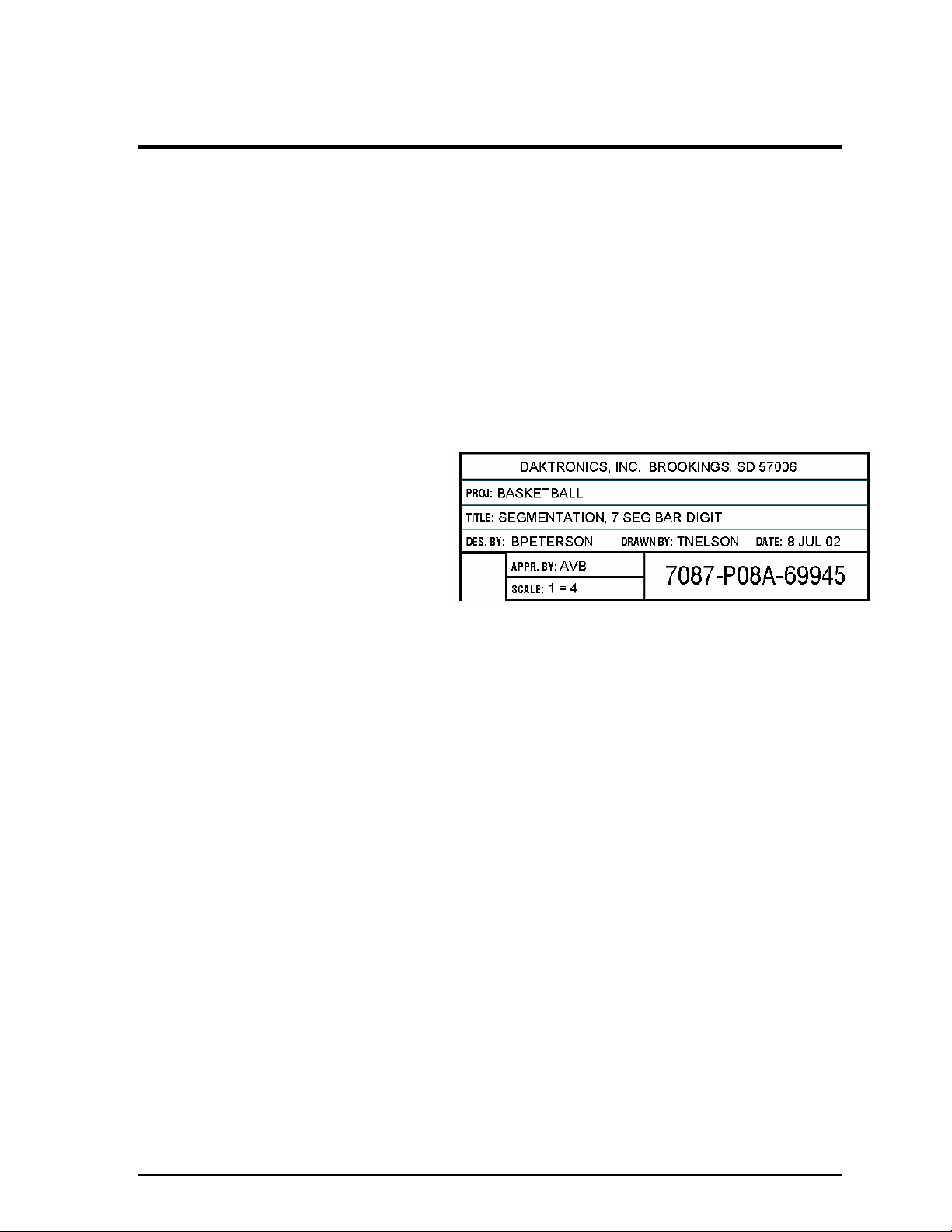
Figure 1 illustrates the
Daktronics drawing
numbering system.
Daktronics identifies
individual engineering
drawings by their drawing
number (7087-P08A-69945
in the example), which is
located in the lower right
corner of the drawing. This
manual refers to drawings by their last set of numbers and the letter preceding them. The
example would be Drawing A-69945.
Reference drawings are grouped and inserted in alphanumeric order in the Appendix.
Listed below are a number of drawing types commonly used by Daktronics, along with the
information that each is likely to provide.
System riser diagrams: overall system layout from control room to display,
power and phase requirements
Shop drawings: fan locations, transformer locations, mounting information,
power and signal entrance points and access method (Front or rear)
Schematics: power wiring, signal wiring, panelboard or power termination
panel assignments, signal termination panel assignments and transformer
assignments
Final assembly: component locations, part numbers, display dimensions and
assembly/disassembly instructions
Figure 1: Daktronics Drawing Label
Introduction 1
Page 6
All references to drawing numbers, appendices, figures, or other manuals are presented in
bold typeface, as in this example: “Refer to Drawing A-66945 for the location of the driver
enclosure.” Additionally, any drawings referenced within a particular subsection are listed at
the beginning of that subsection in the following manner:
Reference Drawing:
Segmentation, 7 Seg Bar Digit................................................................ Drawing A-69945
Daktronics identifies manuals by their engineering document (ED) number, which is located
on the cover page of the manual. For example, this manual would be referred to as ED-13432.
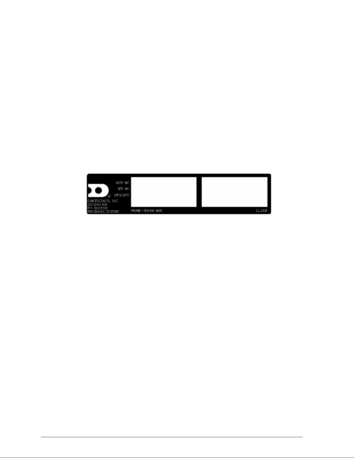
The serial and model numbers of a Daktronics scoreboard can be found on the ID label on the
display. The label will be similar to the one shown in Figure 2. When calling Daktronics
Customer Call Center, please have this information available to ensure quick service. For
future reference, note the scoreboard model number serial number, and installation date on
the second page of this manual.
Figure 2: Scoreboard ID Label
Daktronics displays are built for long life and require little maintenance. However, from time
to time, certain display components will have to be replaced. The Replacement Parts List in
Section 2.3 provides the names and part numbers of components that may require replacement
during the life of this display.
Following the Replacement Parts List is an explanation of Daktronics Exchange and Repair and
Repair Programs. Refer to these instructions if replacement components or repair is needed.
2 Introduction
Page 7

1.2 Daktronics Nomenclature
To fully understand some Daktronics drawings, such as schematics, it is necessary to know
how various components are labeled in those drawings. This information is useful when
trying to communicate maintenance or troubleshooting efforts.
The label “A” on a drawing item typically denotes an assembly. An assembly can be a single
circuit board or a collection of components that function together, usually mounted on a
single plate or in a single enclosure.
In addition, the following labeling formats might be found on various Daktronics drawings:
“TB _ _” denotes a termination block for power or signal cable.
“F _ _” denotes a fuse.
“E _ _” denotes a grounding point.
“J _ _” denotes a power or signal jack.
“P _ _” denotes a power or signal plug for the opposite jack.
Finally, Daktronics part numbers are commonly found on drawings. Those part numbers can
be used when requesting replacement parts from Daktronics Customer Call Center. Take
note of the following part number formats. (Not all possible formats are listed here).
“0P- _ _ _ _- _ _ _ _” denotes an individual circuit board, such as a driver board.
“0A-_ _ _ _ - _ _ _ _” denotes an assembly, such as a circuit board and the plate or bracket
to which it is mounted. A collection of circuit boards working as a single unit may also
carry an assembly label.
“W- _ _ _ _ ” denotes a wire or cable. Cables may also carry the assembly numbering
format in certain circumstances. This is especially true for ribbon cables.
“F- _ _ _ _ ” denotes a fuse.
“T- _ _ _ _ ” denotes a transformer.
“PR- _ _ _ _ _ - _” denotes a specially ordered part.
“M- _ _ _ ” denotes a metal part, and “0M-_ _ _ _ _ _” typically denotes a fabricated
metal assembly.
Introduction 3
Page 8

Page 9

Section 2: Controller Overview
Section 2 includes the following subsections:
All Sport 100
Replacement Parts List: includes the components of the All Sport 100 that may need to be replaced
Daktronics Exchange and Repair and Return Programs: covers the procedure for returning
equipment to Daktronics and/or requesting new parts
2.1 All Sport 100 Overview
®
Overview: identifies the control equipment and how it operates the displays
The All Sport® 100 Series controller, shown in Figure 3, is a
hand-held controller designed to operate Daktronics BB-114
portable basketball scoreboard. This lightweight, 6" high by
1
4
/4" wide controller is encased in ABS plastic, making it a
durable as well as convenient control option. The console’s
liquid crystal display (LCD) will guide you through the
operation of the system.
The All Sport 100, identified by the series number AS-100,
can be configured to display game time, game scores and
possession and bonus information. For details on
configuring the All Sport 100 to operate a display, refer to
Section 3: Basic Operation.
When opening the packages, inspect for shipping damage
such as rattles and dents. See that all equipment is included
as shown on the packing slip. Immediately report any
deficiencies to Daktronics. Save all packing materials for
shipping if warranty repair or exchange is needed.
Figure 3: All Sport 100
Controller Overview 5
Page 10
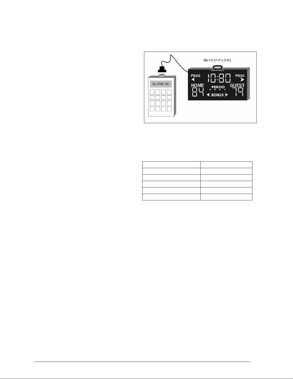
2.2 Display Connection
A 2-pair, shielded cable at 22 AWG
connects the All Sport 100 controller to
Daktronics BB-114 portable basketball
scoreboards.
The cable extends from the XLR jack at
the rear of the BB-114 to the 9-pin jack on
the top of the controller, as shown in
Figure 4.
For more information regarding the BB114 portable basketball display, refer to
ED-13315, the BB-114 Portable LED
Basketball Scoreboard Installation, Maintenance, and Operation Manual
Figure 4: Display Connection
.
2.3 Replacement Parts List
The following is a list of possible
replacement parts for the All Sport 100
controller. When re-ordering a part, be
sure to use its corresponding part
number
.
Part Part Number
All Sport 100 controller 0A-1196-0094
Cable 0A-1196-0095
Clock/score insert LL-2550
Segment timer insert LL-2648
Wall pack transformer T-1118
2.4 Daktronics Exchange and Repair and Return Programs
To serve customers’ repair and maintenance needs, Daktronics offers both an Exchange
Program and a Repair and Return Program.
Exchange Program
Daktronics unique Exchange Program is a quick service for replacing key parts in need of
repair. If a part requires repair or replacement, Daktronics sends the customer a replacement,
and the customer sends the defective part to Daktronics. This decreases display downtime.
6 Controller Overview
Page 11
Before Contacting Daktronics
Identify these important part numbers:
Display Serial Number:
Display Model Number:
Contract Number:
Date Installed:
Location of Sign (Mile Marker Number):
Daktronics Customer ID Number:
To participate in the Exchange Program, follow these steps.
1. Call Daktronics Customer Service:
Market Description Customer Service Number
Schools (primary through community/junior
colleges), religious organizations, municipal clubs
and community centers
Universities and professional sporting events, live
events for auditoriums and arenas
Financial institutions, petroleum, sign companies,
gaming, wholesale/retail establishments
Department of Transportation, mass transits,
airports, parking facilities
2. When the new exchange part is received, mail the old part to Daktronics.
If the replacement part fixes the problem, send in the problem part which is being
replaced.
a. Package the old part in the same shipping materials in which the replacement
part arrived.
b. Fill out and attach the enclosed UPS shipping document.
c. Ship the part to Daktronics.
3. A charge will be made for the replacement part immediately, unless a qualifying
service agreement is in place.
In most circumstances, the replacement part will be invoiced at the time it is shipped.
4. If the replacement part does not solve the problem, return the part within 30
working days or the full purchase price will be charged.
If, after the exchange is made the equipment is still defective, please contact
Customer Service immediately. Daktronics expects immediate return of an exchange
part if it does not solve the problem. The company also reserves the right to refuse
parts that have been damaged due to acts of nature or causes other than normal wear
and tear.
877-605-1115
866-343-6018
866-343-3122
800-833-3157
Controller Overview 7
Page 12

Repair & Return Program
For items not subject to exchange, Daktronics offers a Repair & Return Program. To send a
part for repair, follow these steps:
1. Call or fax Daktronics Customer Service:
Refer to the appropriate market number in the chart listed on the previous page.
Fax: 605-697-4444
2. Receive a Return Material Authorization (RMA) number before shipping.
This expedites repair of the part.
3. Package and pad the item carefully to prevent damage during shipment.
Electronic components, such as printed circuit boards, should be placed in an
antistatic bag before boxing. Daktronics does not recommend Styrofoam peanuts in
packaging.
4. Enclose:
• your name
• address
• phone number
• the RMA number should be written clearly on the outside of the box
• a clear description of symptoms
Shipping Address
Daktronics Customer Service
PO Box 5128
nd
331 32
Brookings, SD 57006
Ave
8 Controller Overview
Page 13

Section 3: Basic Operation
3.1 Console Operation
The console face consists of a two-line-by-16-character liquid crystal display and a sportspecific keyboard insert. In most cases, the top line of the LCD shows the main clock time, the
direction the clock is counting and when the main horn is sounding. Generally, the bottom
line of the LCD displays the home and guest team scores.
Throughout this manual, the names or letters of keys on the keyboard are enclosed in angle
brackets (such as <ENTER*>). Keys and functions common to all sports are explained in
Section 3.5. All of the keys that pertain to a specific sport code insert are explained in detail
in the section of the manual for that specific sport.
3.2 All Sport® 100 Inserts and Codes
Reference Drawings:
Insert; A/S 100 Clock/Score Code-01....................................................Drawing A-167854
Insert; A/S 100 Insert; Baseball .............................................................Drawing A-184219
Insert; LL-2648 Segment Timer Code-06 ..............................................Drawing A-274996
Sport inserts are used to allow a single console to control multiple sports. Select the proper
insert from the chart below and slide it into the insert opening, on the left side of the console,
until it stops. To remove a sport insert, pull on the tab that extends from the left side of the
console. The insert will easily slide out.
The All Sport 100 uses two different keypad
inserts to program game time,
segment/practice timing, game score and
bonus and possession information into
Daktronics BB-114 portable basketball displays.
Segment timing is controlled by sport insert
LL-2648, and all other data is entered using
sport insert LL-2550.
Figure 5 at right illustrates one AS-100 insert
used to control the displays. For more details
on the inserts, refer to the All Sport 100 insert
drawings, Drawings A-167854, and A-274996,
located in Appendix A: Reference Drawings.
If an insert is lost or damaged, a copy of the
insert drawings are located in Appendix A:
Reference Drawings can be used until a
replacement is ordered.
Figure 5: All Sport 100 Insert LL-2648
Basic Operations 9
Page 14

The All Sport 100 controls the Daktronics BB-144 portable basketball displays. Operation of
the displays is discussed in Section 3, Section 4, and Section 5 of this manual. To start up the
controller and use the insert, refer to Section 3. Read the section carefully to fully understand
the operation instructions.
3.3 Sport Insert Operation Concepts
A sport insert identifies keys used in the normal course of operation for a specific sport. In
most cases, pressing a key immediately changes the scoreboard. Sometimes a sequence of
keys must be pressed before a change takes place on the scoreboard. Keys that require entry
of additional information are marked with a dot, for example, <SETx>. The additional
information required usually is a number followed by the <ENTER*> key.
Some keys also include a +1. Pressing one of these keys once increments, or increases, by one
the corresponding field on the scoreboard (such as team score or period). A key with -1
decrements, or decreases, the total of a scoreboard field by one.
On most inserts, certain keys have been grouped together under the headings Home or
Guest. These keys are Team keys, and they work the same for both teams. They affect the
statistics only for the specific home or guest team. Keys not under one of these headings are
Game keys. They are general keys for the progress of the game, such as period or quarter.
Other keys have been blocked together to emphasize that these keys work together.
3.4 Startup
LCD Display Action
ALL SPORT 100
ED-13375 ver 1.0
ENTER CODE 01
clock/score
The console performs a self-test when it is powered on. During the
self-test, a message displays the standard software loaded in the
console.
ED = standard software number
When the self-test completes, the screen displays the last code
entered into controller.
To select a new sport code:
1. Press <CLEAR> to clear the previous code.
2. Get the code number from the sport insert or the section of the
manual for that sport.
3. Use the number keys to enter the new two-digit code. Press
<ENTER*>.
10
Basic Operations
Page 15

3.5 Common Sport Keys
Start
<START> is used to start the main clock
Stop
<STOP> is used to stop the main clock.
Enter/Edit
The <ENTER*/EDIT> key has dual functions. This key functions as the enter key when
editing game data. Pressing the key will accept the new data and end the edit. If not in Edit
mode, the <ENTER*/EDIT> key allows the user to select the item to be edited, such as team
score. After pressing the <ENTER*/EDIT> key, the operator presses one of the increment or
decrement keys for the desired field on the scoreboard. The operator then simply enters the
value he or she wishes to display and presses <ENTER*/EDIT> to accept it.
Clear/Alt
The <CLEAR/ALT> key has also two functions. The key operates as the clear key when
editing game data. Pressing the key will clear the data being edited, or, if pressed twice, will
exit the edit. When not in Edit mode the <CLEAR/ALT> key allows the user to access the
alternate function keys. Pressing the <CLEAR/ALT> and then one of the alternate function
keys will initiate the desired function.
Set Time
LCD Display Action
time edit set
curr mm:ss.t
mm:ss.t = minutes, seconds,
tenths of a second
After the main clock has been stopped, press <SET TIMEx> to
display the current time of the main clock.
To change the time, enter the desired time on the number pad and
press <ENTER*>.
Press <CLEAR> twice to clear changes and return to the game.
Basic Operations 11
Page 16

Count Up/Down
LCD Display Action
MAIN CLOCK-DOWN v
1-UP, 2-DOWN
Up/down = current direction
After the main clock has been stopped, the direction of the clock can
be set.
Press <ALT>, and press <SET TIME> to move to the main clock
menu.
Press <1> or <2> to select Up or Down (default).
Notes: The current direction of the main clock is shown on the top
line of the LCD with an up (u) arrow to show count up and a down (v)
arrow to show count down.
The <COUNT UP/DOWNx> function is disabled while the clock is
running.
Auto Horn
LCD Display Action
AUTO HORN-ON hu
1-ON, 2-OFF
on/off = current setting
To get to the Auto Horn menu, press <ALT>, and then press <AUTO
HORN>.
h appears on the upper right corner of the LCD when the Auto Horn
is enabled. An up/down (uv) arrow also appears to indicate clock
direction.
Press <1> or <2> to select On (default) or Off.
12
Basic Operations
Page 17

Manual Horn
Press <MANUAL HORN> to sound the main horn. The horn sounds as long as the key is
pressed. The horn stops sounding when the key is released.
Dimming
LCD Display Action
Dimming
Level (0-3): none
<0> = none (bright)
<1> = 2/3 (dim)
<2> = 1/2 (dimmer)
<3> = 1/3 (dimmest)
Press <0>, <1>, <2> or <3> to select the intensity for the digits on the
scoreboard. Press <ENTER*> to accept the new dimming level.
Basic Operations
13
Page 18

Page 19

Section 4: Clock/Score Operation
Reference Drawing:
Insert; A/S 100 Clock/Score Code-01.................................................................Drawing A-167854
The All Sport 100 controller enters Clock/Score
information into Daktronics BB-114 portable
scoreboards using sport insert LL-2550, shown at right
in Figure 6. If this insert is lost or damaged, a copy of
the insert drawing, Drawing A-167854, can be used
until a replacement can be ordered.
Refer Section 3 for information on starting the console
and for instructions for use of the sport insert. Read the
Basic Operation material carefully to fully understand
the following operating instructions.
This section provides instructions for using the All
Sport 100 controller to program game time and game
score into Daktronics BB-114 displays. To run the
Clock/Score insert for the BB-114 scoreboard, enter
Code 01 at the Enter Code command.
Figure 6: Clock/Score Insert LL-2550
4.1 Clock Keys
Set Time
The current time on the main clock is displayed by pressing <SET TIMEx> and it can be
changed by entering the desired time on the number pad and pressing <ENTER*>. The
default period length can be edited by pressing <SET TIMEx> a second time
LCD Display
time edit set
curr mm:ss.t*
mm:ss.T = minutes, seconds,
tenths of a second
.
To display the current clock time, press <SET TIMEx>.
To change the current clock time, enter the new time in minutes and
seconds on the number pad and press <ENTER*>.
Press <CLEAR> twice to clear changes and return to the game.
Clock/Score Operations 15
Page 20

LCD Display Action
Time edit edit
Period mm:ss.t*
mm:ss.T= minutes, seconds,
tenths of a second
To display the configured time for period length, press <SET
TIMEx> twice.
To accept the period length as the new clock time, press
<ENTER*>. To decline the selection of the period length,
press <CLEAR>.
To change the period length and set the main clock, enter the
new time in minutes and seconds using the number pad and
press <ENTER*>.
Press <CLEAR> twice to clear changes and return to the
game.
Period +1
LCD Display Action
Period:
edit 2
Press <PERIOD+1> to increment the total.
The LCD shows which key was pressed and the new value.
To edit the period, press the <ENTER*/EDIT> key followed by <PERIOD
+ 1> and then enter the desired number on the keypad. Press
<ENTER*/EDIT> to accept the number.
16
Clock/Score Operations
Page 21

4.2 Score Keys
This section discusses the All Sport 100 controller keys used to input game score, bonus, and
possession information into the BB-114 portable basketball scoreboard.
Home/Guest Score Keys
These scoring keys allow the user to increment the game score by one or two points at a time.
Refer to the tables on the following page for instructions on the use of the Home/Guest Score
keys. The tables use home as an example, but the instructions are the same for both Home
and Guest.
Bonus Keys
These two keys on the All Sport 100 is used to program bonus and possession information
into the BB-114 scoreboard. When either home Bonus or Guest Bonus is selected, the
controller sends the signal to the scoreboard and the corresponding bonus indicator
illuminates. The table uses home as an example, but the instructions are the same for both
Home and Guest.
LCD Display Action
Time mm:ss.t
h= 0 g= o
MM= minutes SS= seconds
T= tenths of a second
Home score +1
1
Time :56.0
h= 1 g= o
Home score -1
0
This screen shown at left is the default screen for
u
h
the Clock/Score All Sport insert. The initial game
score for both teams is zero.
To add points to the home team score, press
<HOME SCORE +1>.This key changes the home
team score by adding one point.
The screen at right appears.
<HOME SCORE +2> operates similarly to the
<HOME SCORE +1> key, as it adds two points to
the home team score instead of one.
To subtract points from the home team score, press
<HOME SCORE -1>. This key changes the score by
subtracting one point.
Clock/Score Operations 17
Page 22

LCD Display Action
Home bonus
On
Home bonus
Off
Pressing the <BONUS g> key toggles bonus information on and off for the
home team.
To program bonus for the home team, press the <BONUS g> key once.
To clear entered bonus information, press the <BONUS g> key again.
Possession Key
This All Sport 100 key is used to send possession information to the BB-114 scoreboard.
When either home possession or guest possession is selected, the controller sends the signal
to the scoreboard, and the corresponding possession indicator illuminates.
LCD Display Action
guest
possession
home possession
Pressing the <POSSESSION g h> key toggles between home and guest
possession. Each of the corresponding screens to the left will appear,
depending upon how many times you press the <POSSESSION g h> key.
Press the <POSSESSION g h> key to toggle between home and guest
possession indicators.
18
Clock/Score Operations
Page 23

Section 5: Segment Timer Operation
Reference Drawing:
Insert; LL-2648 Segment Timer Code-06 ...........................................................Drawing A-274996
The All Sport 100 enters segment timing information
into the Daktronics BB-114, TI-2025 and TI-2026
displays using sport insert LL-2648, shown in Figure 7.
If this insert is lost or damaged, a copy of the insert
drawing, Drawing A-274996, can be used until a
replacement can be ordered.
Refer Section 3 for information on starting the console
and for instructions for use of the sport insert. Read the
Basic Operation material carefully to fully understand
the following operating instructions.
This section provides instructions for using the All
Sport 100 controller to program segment timing into
Daktronics BB-114, TI-2025 and TI-2026 displays. To run
the segment timer for these displays, enter Code 06 at
the Enter Code command.
Figure 7: Segment Timer Insert LL-2648
5.1 Segment Timer Information
The segment timer is used to time events such as practice sessions. The operation of the
segment timer is determined by 40 segments of pre-programmed length. The segment timer
will count down starting at the segment number that is set as First Segment. When the first
segment is completed, the segment timer will count the Interval Time and proceed with the
next segment. The timer will continue counting segments until the segment number that is
set as Last Segment is counted down. It then will reset to the segment saved as the First
Segment and will either begin counting down or pause for the <START> key to be pressed,
depending on the Auto Stop At Last Seg setting. To stop the timer after each segment is
completed, use the Auto Stop feature.
The First Segment and Last Segment values can be used to set up specific practice sessions.
For example, the practice session for one sport could be programmed to use segments 1-10,
while another might use segments 11-20. Set the First Segment and Last Segment values to
the desired segment numbers for the session and the console will count down each of the
segments in order, either stopping on the last segment or looping through included segments
again, based on the Auto Stop At Last Seg setting.
The default First Segment value is 1. The default value for the Last Segment is 40.
Segment Timer Operation 19
Page 24

5.2 Segment Timer Keys
Main Screen
LCD Display Action
SEGMENT: 5
u
h
TIME: 5:00 P2
v= count up/count down
hu/h
P2 = program number
First/Last Segment
LCD Display Action
FIRST SEG XX
LAST SEG YY
XX = current first segment
YY = current last segment
Segment Number/Time
LCD Display Action
SEGMENT: xx
TIME EDIT
xx = segment number
SEGMENT: xx
TIME EDIT nn:nn
xx = segment number
nn:nn = segment time
The main screen, displays which segment number is active and
the amount of time for which that segment is programmed. It
also shows the program number and the direction the clock is
counting.
Press the <FIRST/LAST SEG> key. This setting determines the first
and last segment in a range of segments to run when <START> is
pressed.
Enter the First Segment value and press <ENTER*> to set. Enter the
Last Segment and press <ENTER*> to set and exit.
The console will be reset to the segment saved as First Segment
when the <RESET TO 1ST SEG> key is pressed. The console will
automatically reset to the segment saved as First Segment after the
segment saved as Last Segment is completed.
Press <SEG NOx/TIMEx> to set individual segment times.
Enter the segment to be edited and press <ENTER*>.
Enter the time for the segment and press <ENTER*> to accept and
move to the next segment time.
Press <ENTER*> again to exit the function.
20 Baseball Operation
Page 25

Set Program
LCD Display Action
CURRENT PROG: 2*
Select 1-7
2 = current setting
The segment timer has the ability to select between 7
programs. Program information is saved when powered down.
Press <SET PROGRAM> to change the current program.
Select the desired program with the number pad and press
<ENTER> to accept the changes.
Programs 1-5 allow a unique program for each weekday.
(Monday through Friday)
Program 6 is dedicated to a Play Clock. Program 7 is
dedicated to a Two-Minute Drill.
Interval Time
LCD Display Action
INTERVAL TIME:
nn:nn
nn = current setting
DISPLAY INTERVAL
1–YES 2*NO
* = current setting
The interval time is the time between each segment.
Press <INTERVAL TIMEx> to display the current value of
interval time on the bottom line of the LCD.
Edit the value of the interval time and press <ENTER*>.
If the interval time is set to 00:00, no interval time will be
counted.
This setting determines whether the interval count will be
displayed on the scoreboard.
Press <1> to display the interval time on the scoreboard. Press
<2> to disable the interval time display. The interval time will be
displayed only on the console.
Notes: Regardless of this setting, the value saved in interval
time will be counted down between segments. Set the interval
time to 0 (zero) if no interval between segments is desired
When the interval time is being displayed, the segment number
on the scoreboard flashes to indicate that the time displayed is
interval time. To disable the segment number flash, set the
display interval to NO (<2>).
Segment Timer Operation 21
Page 26

Copy Range
LCD Display Action
COPY: nn:nn*
SEG xx to yy
nn:nn = segment value to be
copied
xx = starting segment value
yy = ending segment value
Press <COPY RANGEx> to set a range of segments to a specific
value.
All segments from xx to yy (inclusive) will be set to the value specified
by nn:nn.
Enter the value specified by the asterisk and press <ENTER*> to
move to the next field.
Auto Stop
LCD Display Action
STOP AT EACH SEG
1*YES 2-NO
*= current setting
STOP AT LAST SEG
1*YES 2–NO
* = current setting
This setting determines the operation of the console when each
segment is completed.
Press <1> to set the console to stop after each segment is
completed. Wait for the <START> key to proceed with the next
segment.
Press <2> to set the console to automatically begin the next
segment when each segment is completed.
If the setting of Auto Stop At Each Seg is NO, the console will
prompt for the Auto Stop At Last Seg setting.
Press <1>or YES to set the console to stop when the last
segment has been completed.
Press <2> or NO to set the console to start over at the first
segment when the last segment is completed
Warning Time
LCD Display Action
Warning time
0:00
0:00 = default
Press <WARNING TIMEx>, enter the time in minutes and seconds and
press <ENTER*>.
Enter 00:00 for no warning time.
When the warning time is reached, the segment number flashes until
the main clock reaches zero.
22 Baseball Operation
Page 27

Reset Current Segment
Press <RESET CURRENT SEG> to reset the segment time to the value specified by the
current segment. The segment number will remain at the current value.
Edit Current Segment
LCD Display Action
SEGMENT: 2
TIME: 5:00 P1
CURRENT SEGMENT
EDIT 02*
* = current setting
u
h
Press <CURRENT SEGMENT + 1> to increment the
segment number by one.
Press <EDIT> <CURRENT SEGMENT +1> to display the
current segment for editing.
Enter the new value for the current segment number and
press <ENTER*>.
Reset to First Segment
Press <RESET TO 1ST SEG> to reset the segment number and segment time to the values
saved as the first segment.
Note: The Reset to First Segment function is disabled while the clock is running.
TI-2025/2026 Segment Timer
Model TI-2025/2026 and TI-2010 include control option 0A-1196-0169. Drawing
A-274283 depicts the system set up.
Send Program Information to Display
LCD Display Action
TRANSFERING DATA
PLEASE WAIT
TRANSFER
COMPLETE
Using the All Sport 100 controller, the user enters the
information for programs 1 to 7. Press <ALT> and then press
<SEND>. The LCD screen will display transferring data.
Wait for approximately 5 seconds until the screen displays
transfer complete, and returns to the main menu. The TI2025/2026 will show “PPPP” on the digits if program was
received successfully. This indicates the information has
been stored into the TI-2025/2026. The All Sport can now be
unplugged, and the displays can be remotely controlled by
the RC-50.
Segment Timer Operation 23
Page 28

TI-2025/2026 Play Clock (Segment Timer Program 6)
Program 6 is dedicated to a play clock. The play clock can be set up to 99 seconds using the
<SET TIME> key.
LCD Display Action
SET PLAY
CLOCK 0:25*
Using the All Sport 100 controller, set the program to 6. Press the
<SET TIME> key. Enter a time using the number keys and press
enter to accept the changes.
LCD Display Action
PLAY CLOCK ↓
TIME: 0:25 P6
Press <START> to start the play clock. Press <STOP> to stop
and reset the play clock.
TI-2025/2026 Two-Minute Drill (Segment Timer Program 7)
Program 7 is dedicated to a Two-Minute Drill clock. This program consists of two different
clocks: the two minute game clock and the 25 second play clock. Press <START> to start the
game clock. Press <STOP> to stop the game clock. Press <CURRENT SEGMENT +1> to
start the play clock. Press <CURRENT SEGMENT +1> again to stop and reset the play
clock.
LCD Display Action
PLAY: 0:25 ↓
MAIN: 2:00 P7
Using the All Sport 100 controller, start the main clock with
<START> and stop the main clock with <STOP>. Start the play
clock with <CURRENT SEGMENT +1>. Press <CURRENT
SEGMENT +1> again to stop and reset the play clock.
24 Baseball Operation
Page 29

RC-50 Segment Timer
Controls (Programs 1-5)
• < START >
• < STOP >
• < RESET PROGRAM >
• < RESET SEGMENT >
• < PROGRAM + >
• < SEGMENT + >
• < HORN >
• < SEGMENT – >
Note: Control operations are exclusive; the All Sport 100 must be unplugged for the RC-50 to
function.
Figure 8: RC-50 Label LL-2649
RC-50 Play Clock Controls (Program 6)
The unique controls for program 6 are listed below.
< STOP > This button stops and resets the play clock.
RC-50 Two-Minute Drill Controls (Program 7)
The unique controls for program 7 are described below.
< START > Starts the game clock.
< STOP > Stops the game clock.
< SEGMENT + > Starts the play clock.
< SEGMENT – > Stops and resets the play clock.
The status indicator light indicates the clock is running.
Figure 9: TI-2025/TI-2026
Segment Timer Operation 25
Page 30

Page 31

Section 6: Baseball Operation
The sport insert drawing is located in Appendix A. If an insert is lost or damaged, a copy of the insert
drawing can be used until a replacement can be ordered.
Refer Section 3 for information on starting the console and for instructions for use of the sport insert.
Read the Basic Operation material carefully to fully understand the following operating instructions.
Use code 03 on the All Sport 100 for baseball.
6.1 Baseball Keys
Out +1, Inning +1
The <OUT +1> and <INNING +1> keys are used to increment their respective totals.
LCD Display Action
Inning +1
nn
nn = current setting
Press <OUT +1> or <INNING +1> to increment their respective
totals.
The LCD shows which key was pressed and the new value.
To change values, first press <EDIT> and <OUT +1> or <INNING
+1> to display the current setting. Enter the correct number on the
number pad and press <ENTER*>.
Baseball Operation 27
Page 32

Ball, Strike, Clear Ball/Strike
The <BALL +1> and <STRIKE+1> keys increment the ball and strike digits. Pressing the
<CLEAR BALL & STRIKE>key clears the digits.
Note: If the ball count value is 4 when <BALL +1> is pressed, the value is blanked out. If the
strike count value is 3 when < STRIKE +1> is pressed, the value is blanked out.
LCD Display Action
Ball: +1
N
Press the <BALL +1> or < STRIKE +1> to increment the ball and strike
digits.
Press the <CLEAR BALL & STRIKE> key to clear the digits to zero.
Hit, Error
The <HIT> and <ERROR> keys are used to turn on the Hit or Error indicator or digits in the
table that follows, <ERROR> is used as an example.
LCD Display Action
Error: ON
Press the <HIT> or <ERROR> key to turn on the hit or error indicator
or digits.
This display appears briefly.
Home/Guest Score +1, -1
The <HOME SCORE +1> and <HOME SCORE -1> and <GUEST SCORE +1> and <GUEST
SCORE -1> keys are used to increment or decrement their respective totals.
LCD Display Action
Team score: +1
HOME nn
nn = current setting
Press the appropriate home or guest <SCORE +1> or
<SCORE -1> key to increment or decrement the total number of runs
for the team. The LCD shows which key was pressed and the new
value for the corresponding team.
The <EDIT> key permits the user to select and edit Runs +1 or –1.
First, press <EDIT> and the key for the home or guest field to be edited,
then enter the correct number on the number pad and press
<ENTER*>.
28 Baseball Operation
Page 33

Appendix A: Reference Drawings
The Daktronics drawing number is located in the bottom right corner of the drawing. This manual
refers to drawings by listing the last set of digits and the letter preceding them.
Insert; A/S 100 Clock/Score Code-01 .......................................................................Drawing A-167854
Insert; A/S 100 Insert; Baseball.................................................................................Drawing A-184219
Insert; LL-2648 Segment Timer Code-06..................................................................Drawing A-274996
Reference Drawings 29
Page 34

Page 35

CLOCK/SCORE
LL-2550 REV 02
0
1 2
3
64
7 8 9
5
CODE 01
Page 36

CODE 03
LL-2572, REV 01
BASEBALL
0
3
6
9
2
5
8
1
4
7
Page 37

 Loading...