

Page 1
Galaxy® Series
AF-3050
Display Manual
®
Galaxy
and Venus® are registered trademarks of Daktronics, Inc. All others are trademarks of
ED13462
Product 1289
Rev 4 – 27 January 2003
Copyright ã 2002-2003 Daktronics, Inc.
All rights reserved. While every precaution has been taken in the preparation
of this manual, the publisher assumes no responsibility for errors or
omissions. No part of this book covered by the copyrights hereon may be
reproduced or copied in any form or by any means – graphic, electronic, or
mechanical, including photocopying, taping, or information storage and
retrieval systems – without written permission of the publisher.
their respective companies
ED13462
331 32nd Ave PO Box 5128 Brookings SD 57006
Tel 605-697-4034 or 877-605-1113 Fax 605-697-4444
www.daktronics.com e-mail: helpdesk@daktronics.com
Page 2

Page 3

Table of Contents
Section 1: Introduction............................................................................................... 1-1
1.1 How To Use This Manual..........................................................................................1-1
1.2 Safety Precautions......................................................................................................1-2
1.3 System Overview .......................................................................................................1-2
1.4 Component Identification...........................................................................................1-3
1.5 Daktronics Nomenclature...........................................................................................1-5
Section 2: Mechanical Installation............................................................................. 2-1
2.1 Installation Requirements...........................................................................................2-1
2.2 Ventilation Requirements...........................................................................................2-1
2.3 Lifting the Display......................................................................................................2-2
2.4 Display Cabinet Mounting.........................................................................................2-2
Section 3: Electrical Installation................................................................................ 3-1
3.1 Common Connectors in the Display...........................................................................3-1
3.2 Control Cable Categories...........................................................................................3-2
Unshielded Cable.................................................................................................3-2
Shielded Cable.....................................................................................................3-2
Direct Burial Cable..............................................................................................3-2
High Voltage Insulation Cable.............................................................................3-2
3.3 Conduit.......................................................................................................................3-3
3.4 Preparing for Power/Signal Connection.....................................................................3-3
3.5 Power..........................................................................................................................3-4
Grounding............................................................................................................3-4
Power Installation................................................................................................3-4
3.6 Signal..........................................................................................................................3-5
RS422 Cable Requirements.................................................................................3-5
Signal Connection from Computer to Sign..........................................................3-5
Signal Termination Betwee n Two (or Mo re) Signs.............................................3-5
3.7 First Time Operation..................................................................................................3-5
3.8 Main Disconnect.........................................................................................................3-2
Section 4: Maintenance and Troubleshooting.......................................................... 4-1
4.1 Maintenance and Troubleshooting Overview ............................................................4-1
4.2 Signal Summary.........................................................................................................4-1
Modem.................................................................................................................4-1
4.3 Power Summary.........................................................................................................4-2
4.4 Service and Diagnostics.............................................................................................4-2
Transformer, RFI Filter and Fuse........................................................................4-2
Controller.............................................................................................................4-3
Modules and Drivers............................................................................................4-4
Power Supplies ....................................................................................................4-5
Table of Contents
i
Page 4

Light Detector ..................................................................................................... 4-6
4.5 Thermostats................................................................................................................ 4-6
4.6 Ventilation Systems (With Fans and Filters)............................................................. 4-6
4.7 Galaxy Display Maintenance..................................................................................... 4-7
4.8 Weather Stripping...................................................................................................... 4-7
4.9 Troubleshooting......................................................................................................... 4-8
4.10 Initial Operation Information..................................................................................... 4-8
4.11 Replacement Parts List.............................................................................................. 4-9
4.12 Daktronics Exchange and Repair and Return Programs............................................ 4-9
Appendix A: Reference Drawings ................................................................................. A-1
ii
Table of Contents
Page 5

List of Figures
Figure 1: Drawing Label ......................................................................................................................1-1
Figure 2: Controller..............................................................................................................................1-3
Figure 3: 16x16Pixel Module (Front and Rear)...................................................................................1-4
Figure 4: Module Numbering Example – 24x80 Front........................................................................1-5
Figure 5: Module Numbering...............................................................................................................1-5
Figure 6: Typical Label........................................................................................................................1-5
Figure 7: Lifting the Display................................................................................................................2-2
Figure 8: Ribbon Cable Connector.......................................................................................................3-1
Figure 9: Termination Block................................................................................................................3-1
Figure 10: Phoenix Connector..............................................................................................................3-1
Figure 11: Mate-n-Loc Connector........................................................................................................3-2
Figure 12: RJ11/ RJ45 Connector ........................................................................................................3-2
Figure 13: Controller Component Layout............................................................................................4-3
List of Figures
iii
Page 6

Page 7
Section 1: Introduction
1.1 How To Use This Manual
This manual explains the installation and maintenance of Galaxy® 20mm series AF-3050 displays. For
questions regarding the safety, installation, operation, or service of this system, please refer to the
telephone numbers listed on the cover page of this manual.
The manual is divided into five sections: Introduction, Mechanical Installation, Electrical Installation,
Maintenance and Troubleshooting, and Appendix A.
· Introduction: Covers the basic information needed to make the most of the rest of this manual.
Take time to read the entire introduction as it defines terms and explains concepts used throughout
the manual.
· Mechanical Installation: Provides general guidance on sign mounting.
· Electrical Installation: Offers general guidance on terminating power and signal cable at the
sign.
· Maintenance and Troubleshooting: Addresses such things as removing basic sign components,
troubleshooting the sign, performing general maintenance and exchanging sign components.
· Appendix A: Includes the drawings referenced in this manual.
Daktronics identifies manuals by an ED number located on the cover page of each manual. For
example, this manual would be referred to as ED13462.
Listed below are a number of drawing types commonly used by Daktronics, along with the
information that each is likely to provide. This manual might not contain all these drawings.
· System Riser Diagrams: Overall system layout from control computer to sign, power and phase
requirements.
· Shop Drawings: Fan locations, mounting information, power and signal entrance points and
access method (front and rear).
· Schematics: Power and signal wiring for various components.
· Component Placement Diagrams: Locations of critical internal sign components such as power
supply assemblies, controller boards, thermostats and light detectors.
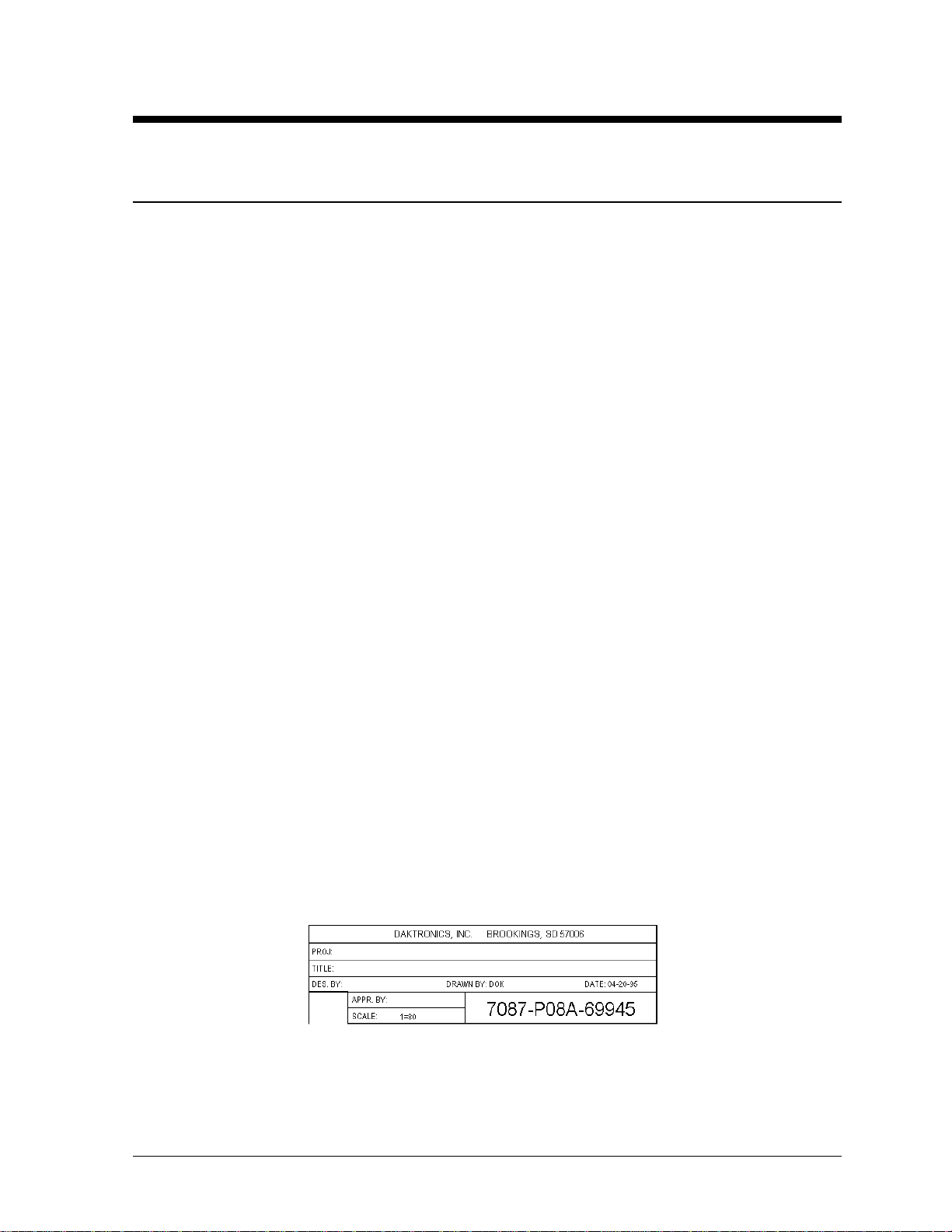
Figure 1 below illustrates Daktronics drawing label. The drawing num ber is located in the low e r-right
corner of the drawing. Listing the last set of digits and the letter preceding them identifies drawings in
the manual. In the example below, the drawing would be referred to as Drawing A-69945. Reference
drawings are inserted in Appendix A.
Introduction
Figure 1: Drawing Label
1-1
Page 8
All references to drawing numbers, appendices, figures, or other manuals are presented in bold
typeface, as shown below.
“Refer to Drawing A-69945 in Appendix A for the power supply location.”
Additionally, drawings referenced in a particular section are listed at the beginning of that section as
seen in the following example:
Reference Drawing:
Component Placement Diagram............................................................Drawing A-69945
Daktronics signs are built for long life and require little maintenance. However, from time to time,
certain sign components will need replacing. The Replacement Parts List in Section 4.11 provides
the names and part number of components that may need to be ordered during the life of the sign.
Most sign components have a white label that lists the part number. The component part number is in
the following format: 0P-_ _ _ _-_ _ _ _ (circuit board) or 0A-_ _ _ _-_ _ _ _ (multi-component
assembly).
Following the Replacem ent Parts List is the Daktronics Exchange and Repair and Return
Programs in Section 4.12. Refer to these instructions if any sign component needs replacement or
repair.
1.2 Safety Precautions
Important Safeguards:
1. Read and understand these instructions before install in g .
2. Be sure the sign is properly grounded.
3. Disconnect power when servicing the sign.
4. Do not modify the sign structure or attach any panels or coverings to the sign without
the written consent of Daktronics, Inc.
1.3 System Overview
Daktronics Galaxy AF-3050 signs are designed and manufactured for performance, reliability, easy
maintenance and long life. The pixels have a 20mm center-to-center spacing, and are lit using LEDs
(light emitting diodes). Each sign section has minimum 6-inch character height. A light sensor on the
front of the sign is used for automatic dimming of the LEDs based on the ambient light levels. The
configuration of pixels depends on the model of sign ordered.
The Galaxy model numbers are described as follows: AF-3050-CCCxBBB-20-R
AF-3050
CCC
BBB
20
R
= Outdoor Galaxy Sign
= Number of Rows High
= Number of Columns Long
= 20mm center-to-center spacing with 6"
Minimum Character Height
= LED Color (Monochrome Amber or Red)
1-2
Introduction
Page 9
1.4 Component Identification
The following illustrations depict some of the more commonly accessed Galaxy sign components.
Because Daktronics occasionally alters standard design to meet customer needs, the actual sign design
may very slightly from the illustrations below.
This is only a brief overview. Refer to Section 4 for more detailed information on maintaining and
troubleshooting various sign components.
Com Port: Connector on the back of the control computer. The COM port is used to control the sign
network through either a 9- or a 25-pin serial connector.
Controller: “Brains” of the sign (refer to Figure 2 below). The controller receives signal information
from the control computer, translates it, and activates the appropriate pixels on the sign accordingly.
Figure 2: Controller
Galaxy
®
: Daktronics trademarked name for LED monochrome or tri-colored matrix signs.
Network: Consists of multiple signs connected to each other.
RS422: Standard differential communication type with a maximum cable length of 4000 feet (1.2
kilometers).
Sign Address: Identification number assigned to each sign of a network. It is set by flipping DIP
switches on the controller. The control software uses the address to locate and communicate with each
sign. Signs that are on the same network cannot have the same address.
Signal Converter: Daktronics supplied unit that converts the data from RS232 to RS422. The signal
converter is usually used in RS422 systems.
Refer to Figure 3 on the following page while reading the following component descriptions.
Introduction
1-3
Page 10
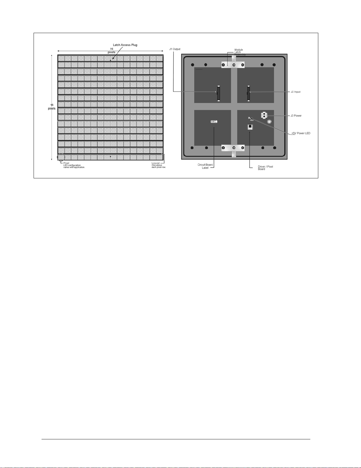
Figure 3: 16x16Pixel Module (Front and Rear)
Driver/Pixel Board: The LED pixels are mounted directly onto the driver/pixel board. This board is
also responsible for the switching and intensity levels of the LEDs.
LED (light emitting diode): Low energy, high intensity lighting units.
Louver: Optional black plastic shade positioned horizontally above each pixel row. The louvers
increase the level of contrast on the sign face and direct LED light.
Module: 20mm Galaxy modules are 16 pixels high by 16 pixels wide (refer to Figure 3 above). Each
module is individually removable from the front of the sign.
Module Latch Assembly: Device utilizing a rotating retainer bar to hold the module firmly to the
sign frame. There are two per module: one near the top and one near the bottom.
Pixel: Cluster of LEDs. The number and color of the LEDs depends on sign application.
Power Supply: Converts AC line voltage from the load center to low DC voltage for one or more
module driver boards.
1-4
Introduction
Page 11
1.5 Daktronics Nomenclature
To fully understand some Daktronics
drawings, such as schematics, it is
necessary to know how various
components are labeled in those
drawings. This inform ation is also
useful when trying to communicate
maintenance or troubleshooting efforts.
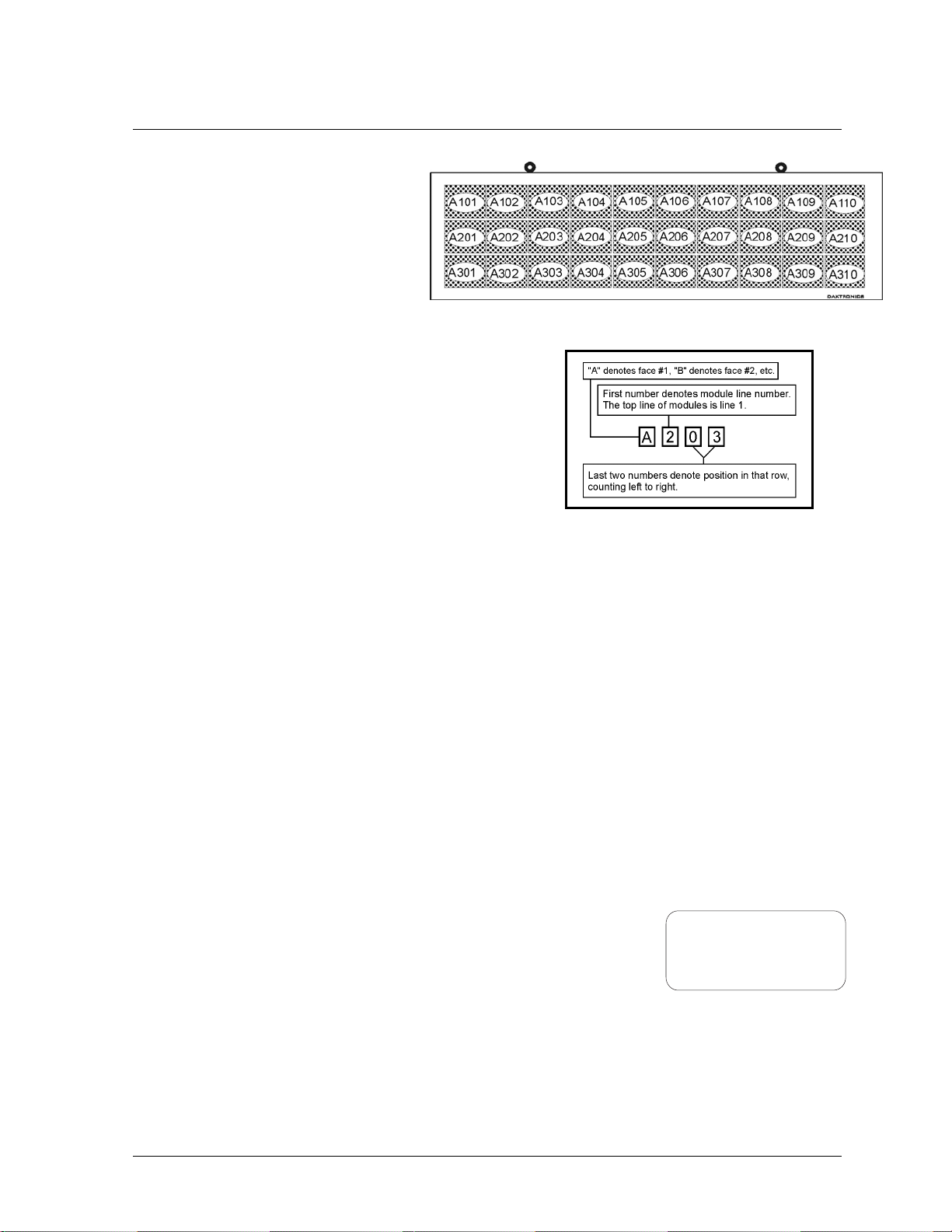
A module is the building block of the
Galaxy sign. Each module measures 16
pixels high by 16 pixels wide. By placing modules side-byside and on top of one another a sign of any size can be
designed and built. Individual modules can be easily
removed from the sign if required. Figure 4 above
illustrates how Daktronics numbers modules on a Galaxy
sign. Figure 5 on the right breaks down the module
numbering method.
The label “A” on a drawing typically denotes an assembly.
An assembly can be a single circuit board or a collection of
components that function together, usually mounted on a single plate or in a single enclosure.
Assemblies are divided into two types: those that route signal and those that route power.
In addition, the following labeling formats might be found on various Daktronics drawings:
· “TB_ _” indicates a termination block for power or signal cable.
· “F_ _” signifies a fuse.
· “E_ _” stands for a grounding point.
· “J_ _” represents a power or signal jack.
· “P_ _” symbolizes a power or signal plug for the opposite jack.
Finally, Daktronics part numbers are commonly found on drawings. Those part numbers can be used
when requesting replacement parts from Daktronics Customer Service. Take note of the following part
number formats:
· “0P-_ _ _ _-_ _ _ _” designates an individual circuit board, such as a line receiver.
· “0A-_ _ _ _-_ _ _ _” indicates an assembly, such as a circuit board and the plate or bracket to
which it is mounted. A collection of circuit boards working as a single unit may also carry an
assembly label.
· “W-_ _ _ _” denotes a wire or cable. Cables may also carry the
assembly numbering format in certain circumstances. This is
especially true of ribbon cables.
· “F-_ _ _ _” specifies a fuse.
Most circuit boards and components within this sign carry a label that lists the part number of the unit.
If a circuit board or assembly is not listed in the replacement parts list in Sec tion 4, use the label to
order a replacement. A typical label is show n in Figure 6 above. The part number is in bold.
Introduction
Figure 4: Module Numbering Example – 24x80 Front
Figure 5: Module Numbering
0P-1195-0001
SN: 6343
05/19/99 REV.1
Figure 6: Typical Label
1-5
Page 12

Page 13

Section 2: Mechanical Installation
The Daktronics engineering staff must approve any changes made to the display. Before altering the
display, detailed drawings for the proposed modifications must be submitted to the Daktronics
engineering staff for evaluation and approval or the warranty will be rendered null and void.
Note: Daktronics does not guarantee the warranty in situations where the display is not constantly in a
stable environment.
2.1 Installation Requirements
An adequate support structure and mounting hardware must be present to mount the sign in a safe and
stable manner. It is the inst all er’s respons ibi li ty to ensure the mounting structure and mounting
hardware are capable of supporting the display, and will agree with local codes.
Before beginning the installation process, verify the following:
· The mounting structure will provide a straight and square-mounting frame for the display.
· The mounting structure is capable of supporting the display and will not yield at any unsupported
points after mounting.
· Clearance: 3" of unobstructed space is available below the display for proper ventilation of the
sign. Unobstructed space is needed for eyebolt removal/clearance above the sign. Additional space
may be required depending on the mounting method used.
Correct any deficiencies before installation.
Note: Daktronics is not responsible for the support structure or structural integrity of the mounting
structure.
2.2 Ventilation Requirements
Fans are mounted in the bottom of the sign for ventilation. Maintain a minimum distance of
3" (7.62-cm) below the sign to maintain proper airflow.
If the sign cabinet is completely enclosed:
· 12 square inches of unobstructed opening per module must be provided to ensure adequate
cooling.
· Allowances must be made to compensate for the percentage of material covering the openings in
the structure.
· For adequate cooling, forced ventilation may be required. If air is forced into the enclosed cabinet,
19 cubic feet per minute must be provided per module (12.48" x 12.48 " active area).
If these requirements are not met, the Galaxy sign warranty may be void.
Mechanical Installation
2-1
Page 14
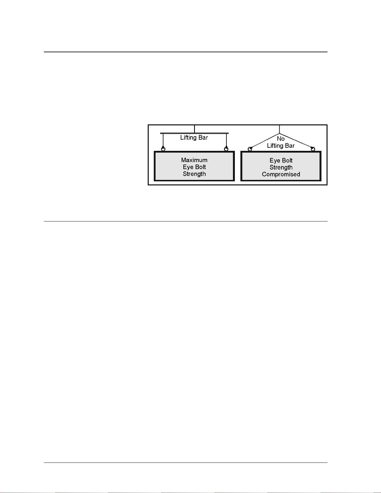
2.3 Lifting the Display
The top of the display is equipped with eyebolts that are used to lift the unit. Take spec ial care not to
exceed the rated load of the eyebolts. Refer to the information at the end of this section to determine
the allowable load of the eyebolts.
Figure 7 below illustrates both the correct (left example) and the incorrect (r ig ht example) method
of lifting a display. By using the non-recommended form on the right, the eyebolt may break. Lift the
display as shown on the left, with the lifting bar. Use every lifting point provided.
Do not attempt to permanently
support the display by the
eyebolts.
If removing the eyebolts,
adequately seal the holes using 13
bolts and sealing washers, ½ inch
in size. Silicone along the threads.
This ensures that water does not
enter the display.
Figure 7: Lifting the Display
2.4 Display Cabinet Mounting
1. Carefully uncrate the display. Look each side of the display over for signs of damage during
shipping.
2. Following the guidelines described in Section 2.3, lift the display into position on the support
structure.
3. Because mounting design will vary for the sign, Daktronics cannot provide additional detailed
information. Follow the instructions provided by the sign company for mounting your particular
sign(s).
4. Refer to Section 1 for information on routing power and signal.
Refer to Section 3 for wiring instructions.
2-2
Mechanical Installation
Page 15
Section 3: Electrical Installation
Only a qualified individual should terminate power and signal cable within this Daktronics
display.
The Daktronics engineering staff must approve any changes made to the display. Before altering the
display, submit detailed drawings for the proposed modifications to the Daktronics engineering staff
for evaluation and approval or the warranty will be rendered null and void.
3.1 Common Connectors in the Display
The power and signal connections in the displays use many different types of
connectors. Take special care when disengaging any connector so as not to
damage the connector, the cable or the circuit board.
When unplugging a connector plug from a jack, do not pull on the wire or
cable; pull on the jack itself. Pulling on the wires may damage the connector.
The following information presents some common connectors encountered
during display installation and maintenance:
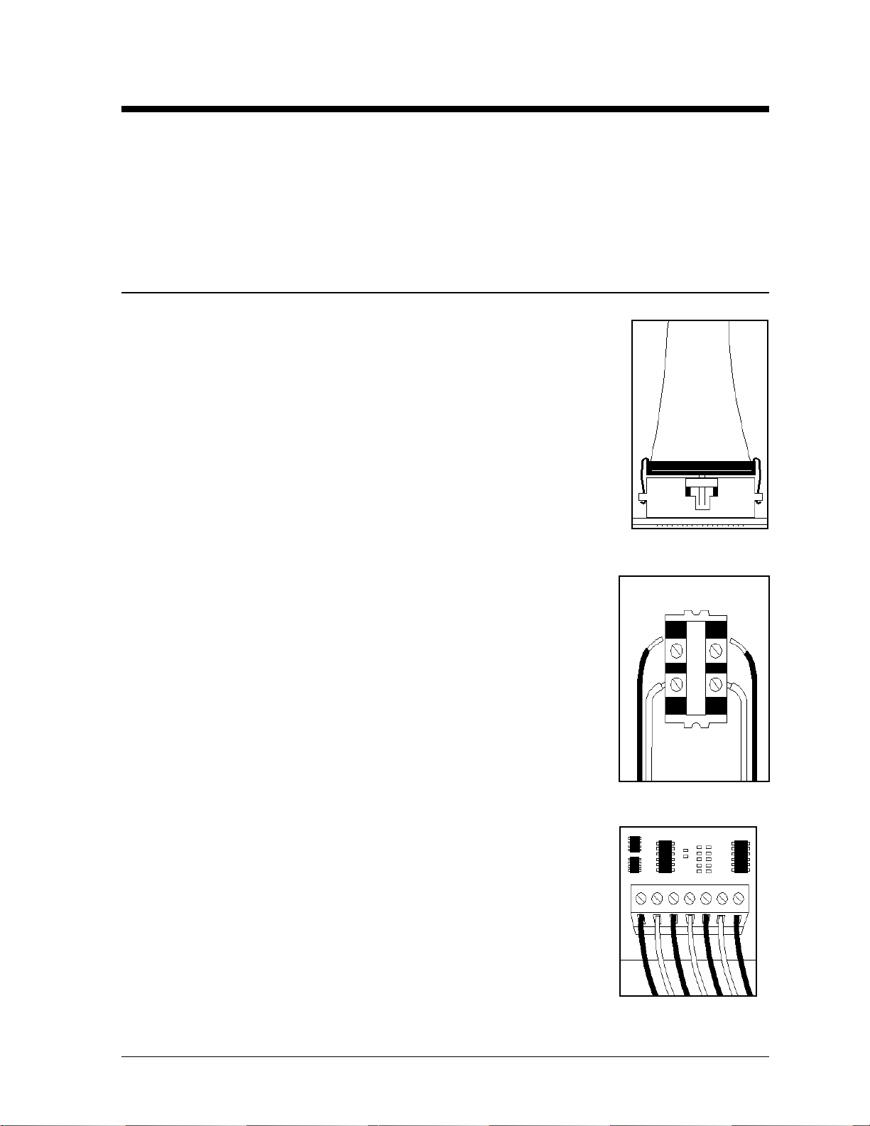
1. Ribbon Cable Connectors:
Figure 8 on the right illustrates a typical ribbon connec tor. To disconn ec t
the ribbon cable, push the metal clips on the sides to unlock and remove
the jack.
Before replacing a ribbon cable connector, spray it with Deoxit™ contact
cleaner to remove any foreign matter that may cause signal problems. In
addition, apply a generous amount of Cailube
™
protector paste to the
plug before inserting it into the jack. This paste will protect both the
plug and the jack from corrosion.
2. Termination Blocks:
Termination blocks are usually used to connect internal power and
signal wires to wires of the same type coming into the display from an
external source. Most signal wires will come with forked connectors
crimped to the ends of the wire. Power wires need to have one-half inch
of insulation stripped from the end of the wire prior to termination.
Tighten all screws firmly to ensure a good electrical connection. Refer to
Figure 9 on the right.
3. Phoenix
ä
-Style Connectors:
Phoenix-style connectors, which are usually green, are often used for
signal termination on circuit boards. Refer to Figure 10 on the right.
Strip one-quarter inch of insulation from the wire prior to termination.
To remove a wire, turn the above screw counter-clockwise to loose the
connectors grip on the wire. To insert a wire, push the bare wire into the
connector and turn the above screw clockwise to lock the wire into
place.
Figure 8: Ribbon
Cable Connector
Figure 9: Termination
Block
Figure 10: Phoenix
Connector
Electrical Installation
3-1
Page 16
ä
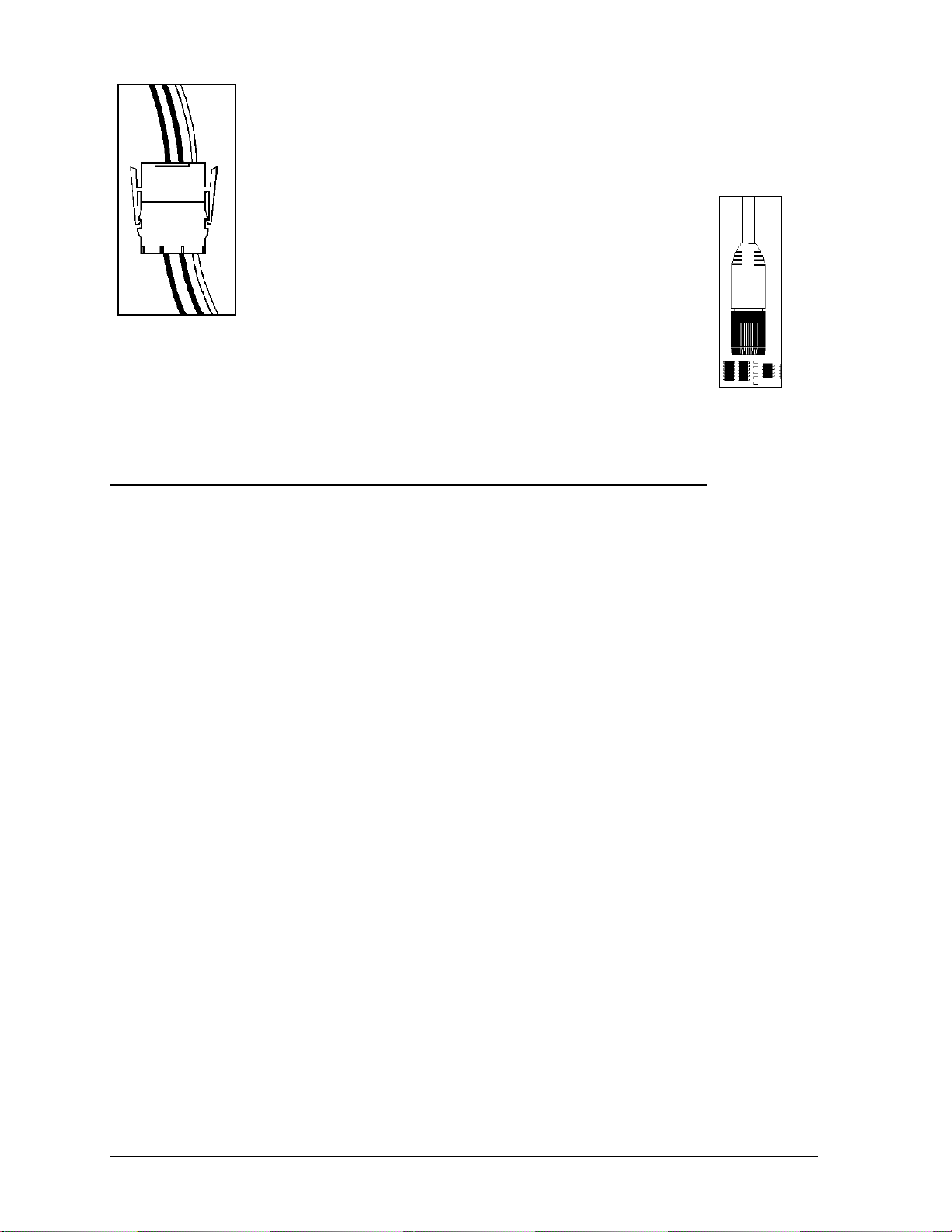
4. Mate-n-Lok
Connectors:
The Mate-n-Lok connectors found in the displays are white and come in a variety
of sizes. Figure 11 on the left illustrates a five-pin Mate-n-Lok connector. To
remove the plug form the jack, squeeze the plastic locking clasps on the side of
the plug and pull it from the jack.
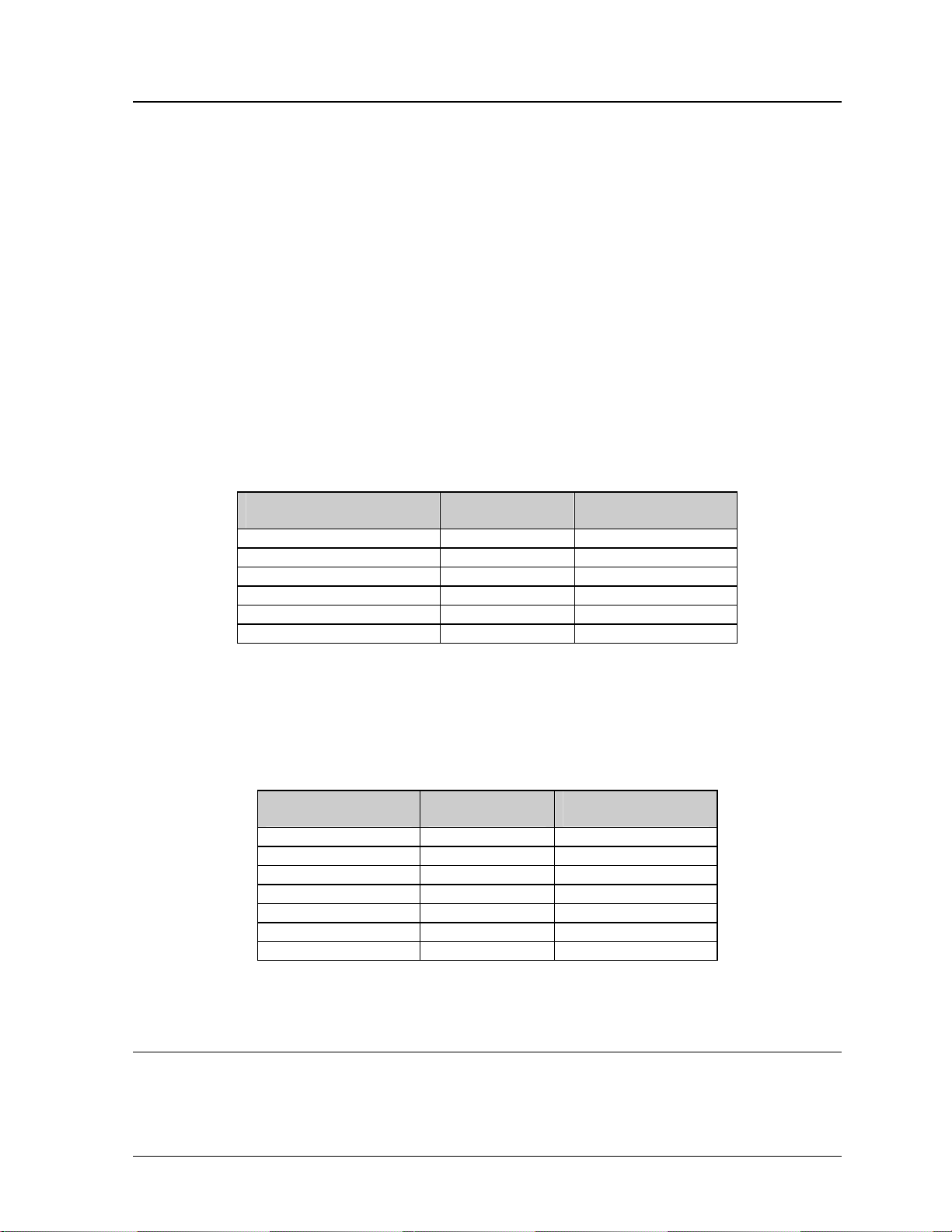
5. Phone Jacks (RJ11/RJ45 Connectors):
RJ connectors, as seen on the right in Figure 12, are similar to the
telephone connectors found in homes and are used on the ends of
RJ45 cable. In order to remove this plug from the jack, depress
the small clip on the underside of the plug.
Figure 11: Maten-Loc Connector
Before replacing an RJ connector, spray it with Deoxit
™
contact
cleaner to remove any foreign matter that may cause signal
problems. In addition, apply a generous amount of Cailube
protector paste to the plug before inserting it into the jack. This
paste will protect both the plug and the jack from corrosion.
™
Figure 12:
RJ11/ RJ45
Connector
3.2 Control Cable Categories
Daktronics has identified four general categories for control cable. Most commonly used for
installation in conduit are shielded and unshielded cable.
Unshielded Cable
Unshielded cable consists of paired wires. These wires should not be subjected to mechanical
flexing after installation. This cable is not for direct burial and should have one of the following
routings:
· In dedicated metallic conduit
· In plastic conduit away from interference signals
· Inside buildings – if cable is not in conduit, keep away from interference signals
Shielded Cable
This cable has stranded wire that is paired and overall shielded, and may be subjected to
interference signals. It does not need to have a dedicated metallic conduit. The shield must be
properly terminated at the controller. The cable can be subjected to some flexing after installation.
Cable is not for direct burial. Do not use this in conduit with power conductors.
With interference signals, such as power conductors, intercom, etc., a two-foot separation is
typically required.
Direct Bur a Cab e i l l
This application uses a paired, overall shielded, solid, direct burial cable. It is intended that this
cable type be typically used underground without conduit.
High Voltage nsula ion Cable
I t
This cable uses an individually shielded pair of stranded wires. The insulation rating is 600V and
60 degrees Celsius. Cable routing may be with power conductors. This category is discouraged
when other routing is possible. The National Electr ic Code has speci fic req ui rements concerning
the voltage rating of cables with power conductors. All applicable electrical and building codes
must be followed.
3-2
Electrical Installation
Page 17

Conduit, and the labor to pull cable through the conduit, is the res pons ibili ty of the custom er
and/or contractor.
3.3 Conduit
Daktronics does not include the conduit. Separate conduit must be used to route:
· Power
· Signal IN wires
· Signal OUT wires (if signal is required for another sign)
· Temp sensor
The conduit holes should located at the bottom right (rear view) of the back of the sign.
Punch or drill out the desired conduit openings. Be careful that none of the internal components
are damaged. Attach the conduit and route the power and signal cables. Refer Figure 3 for a picture
of the power and signal termination panels.
For signs with more than one face, signal and temperature sensor wiring between signs can be routed
through the same conduit.
3.4 Preparing for Power/Signal Connection
1. Punch in ½" knockouts (0.875 holes) or drill 7/8" (0.875) holes for the desired conduit openings.
Be careful that none of the internal components are damaged. Attach the conduit. Refer to the
component layout drawing specific to your sign type for internal components.
2. Remove the bottom left two modules (AX01 and AX02) to expose the power enclosure and signal
panel. To do this, use a
1/8-inch Allen wrench to turn the latch access fasteners one-quarter turn.
Turn the top latch clockwise and the bottom latch counter-clockwise. Lift the module away from
the display, then reach behind it and disconnect all power and signal connections.
3. Locate the controller for these displays. The controller is shown in Figure 2 located within
Section 1.4. The controller receives the incoming signal and relays it to the individual modules.
Now locate the power termination box. These are located according to component replacement
drawings.
4. Route power to the display through a fused disconnect switch capable of opening all ungrounded
power conductors. Install this disconnect within the line of sight of any personnel performing
maintenance on the display. If the disconnect is located out of sight of the display, it must be
capable of being locked in the open position.
5. Power conductors from the disconnect to the display should be routed through conduit in
agreement with local code.
6. You may route the signal cable from the control computer to the sign at this time also. Be sure to
run the power and signal cables in a separate conduit.
Electrical Installation
3-3
Page 18

3.5 Power
Proper power installation is imperative for proper display operation. The following sub-sections give
details of display power installation. Qualified personnel must perform electrical installations.
Unqualified personnel should not attempt to install the electrical equipment. Serious danger to
equipment and personnel could occur if equipment is improperly installed.
G ounding r
Displays must be grounded according to the provisions outlined in Article 250 of the National
Electrical Code
®
. Daktronics recommends a resistance to ground of 10 ohms or less. The electrical
contractor who is performing the electrical installation can perform verification of ground
resistance. Daktronics Sales and Service personnel can also perform this service
The display system must be connected to earth-ground. Proper grounding is necessary for reliable
equipment operation. It also protects the equipment from damaging electrical disturbances and
lightning. The display must be properly grounded or the warranty will be void.
The material of an earth-ground electrode differs from region to region and from conditions
present at the site. Consult the National Electrical Code and any local electrical codes that may
apply. The support structure of the display cannot be used as an earth-ground electrode. The
support is generally embedded in concrete, and if in earth, the steel is either primed or it corrodes,
making it a poor ground.
Power Installation
There are two considerations for power installation: installation with ground and neutral
conductors provided and installation with only a neutral conductor provided. These two power
installations differ slightly, as described in the following paragraphs:
Installation with Ground and Neutral Conductors Provided
For this type of installation, the power cable must contain an isolated earth-ground conductor.
Under this circumstance, do not connect neutral to ground at the disconnect or at the display.
This would violate electrical codes and void the warranty. Use a disconnect so that all hot
lines and neutral can be disconnected. The National Electrical Code requires the use of a
lockable power disconnect within sight of or at the display.
Installation with Only a Neutral Conductor Provided
Installations where no grounding conductor is provided must comply with Article 250-32 of
the National Electrical Code. If the installation in question meets all of the requirements of
Article 250-32, the following guidelines must be observed:
· Connect the grounding electrode cable at the loc a l dis c onnec t, never at the disp lay driver
enclosure.
· A disconnect that opens all of the ungrounded phase conductors should be used.
· The neutral and the ground conductors should be bonded at the ground lug termination
point in the receptacle within the display driver enclosure.
3-4
Electrical Installation
Page 19
3.6 Signal
RS422 Cable Requirements
This cable is a 6-conductor shielded cable used to transmit an RS/422 signal. This shielded cable
consists of unpaired wires. They should not be subjected to mechanical flexing after installation.
This cable is not for direct burial and should have one of the following routings:
· In dedicated metallic conduit
· Inside buildings - if cable is not in conduit, keep away from interference signals.
With interference signals (such as power conductors, intercom, etc.) typically a two-foot
separation is required. The maximum length of an RS/422 signal cable is 4,000 feet (1.22
kilometers).
Signal Connect on from Compu er to Sign i t
One end of the signal cable should be terminated to the 6-position terminal block in the sign
labeled “RS422 IN” (TB2). The opposite end is terminated at the signal converter (Daktronics part
number 0A-1127-0237) in the control room.
Signal Converter (J4/J5) Field Cabling
Pin 1 (GND) Red Pin 1 (GND)
Pin 2 (RX-P) Black Pin 2 (TX-P)
Pin 3 (RX-N) Brown Pin 3 (TX-N)
Pin 4 (TX-P) White Pin 4 (RX-P)
Pin 5 (TX-N) Blue Pin 5 (RX-N)
Pin 6 (GND) Green Pin 6 (GND)
Terminal Block TB2
(RS422 In)
Signal Termination Between Two (o More) Signs r
This is the most common method of terminating signal between two or more signs. A 6-conductor
cable is used and one end terminates at the “RS422 OUT” 6-position terminal block (TB3) on the
first sign. The other end terminates at the “RS422 IN” 6-position terminal block (TB2) in the
second sign.
Sign A
Data Out (TB3)
Pin 1 (GND) Green Pin 6 (GND)
Pin 2 (Data TX-N) Blue Pin 5 (Data RX-N)
Pin 3 (Data TX-P) White Pin 4 (Data RX-P)
Pin 4 (Data RX-N) Brown Pin 3 (Data TX-N)
Pin 5 (Data RX-P) Black Pin 2 (Data TX-P)
Pin 6 (GND) Red Pin 1 (GND)
Pin 6(GND) Bare (Shield) N.C.
Field Cabling
Sign B
Data In (TB2)
Note: Refer to Section 4.2 for the modem information. This is found on pages 4-1 and 4-2.
3.7 First Time Operation
When first operated, the sign will run through an initialization in which it will display the following:
1. Output Test (DDDs)
2. Product Name (Galaxy)
3. Sign Size (Row x Column)
4. Firmware Number (ED10134)
Electrical Installation
3-5
Page 20

5. Firmware Revision (Rev X.XX)
6. COM1 Configuration (C1: V15/RTD)
7. COM2 Configuration (C2: None)
8. Line Frequency (60 Hz)
9. Hardware Address (HW: XX)
10. Software Address (SW: XX)
11. Sign Name
12. Modem if Present (Modem)
3.8 Main Disconnect
The National Electrical Code requires the use of a lockable power disconnect near the sign. Provide a
lockable disconnect switch (knife switch) at the sign location so that all power lines can be completely
disconnected. Use a 3-conductor disconnect so that both hot lines and the neutral can all be
disconnected. The main disconnect should be mounted at or near the point of power supply connection
to the sign. A main disconnect is to be provided for each supply circuit to the sign.
The disconnecting means must be located in a direct line of sight from the sign or outline lighting that
it controls. This requirement provides protection by enabling a worker to keep the disconnecting
means within view while working on the sign.
Exception: Disconnecting means that are capable of being locked in the open position may be located
elsewhere.
3-6 Electrical Installation
Page 21

Section 4: Maintenance and Troubleshooting
Important Notes:
1. Power must be turned off before any repair or maintenance work is
done on the display.
2. Qualified service personnel must make any access to internal display
electronics.
3. The Daktronics engineering staff must approve ANY changes made to
the display. Before altering the display, detailed drawings for the
proposed modifications must be submitted to the Daktronics
engineering staff for evaluation and approval or the warranty will be
rendered null and void.
4.1 Maintenance and Troubleshooting Overview
The 20mm Galaxy displays are front accessible; meaning access to the internal com ponents can be
gained only from the front of the display.
This section provides the following Galaxy display information:
· Signal Routing Summaries: Provide a basic explanation of the power travel through the display.
· Power Routing Summaries: Offer a basic explanation of the power travel through the display.
· Service and Diagnostics: Give instructions for removing various display components and
explains the functions of circuit board connectors and the meanings of any diagnostic LEDs.
· Maintenance: Records a number of steps to take to keep this Galaxy display in safe, working
order.
· Troubleshooting: Supplies some possible display malfunctions and provides a number of
possible causes for that malfunction.
· Replacement Parts List: Recommends the descriptions and numbers of display components that
could possibly need replacing during the life of this display.
· Daktronics Exchange and Repair and Return Programs: Explain the Daktronics component
return policy.
4.2 Signal Summary
The signal routing for the display can be summarized as follows:
1. Data from the controller computer travels via an RS422 cable into face “A” of the display.
2. RS422 cable relays signal between the face “A” contro l ler and the fac e “B” contro ller.
3. The signal then travels over a 40-conductor ribbon cables from J11/J12 on the controller to P2 on
the driver of the first column of modules in each display face.
4. Data exits at J1 and is relayed to J2 of the next driver board. The data from the controller jack
travels down the entire row of modules. The drivers use this display data to control the LEDs.
Modem
If a modem was ordered with the display, it will be mounted inside the display cabinet, near the
controller. The modem is used in lieu of a direct communication line with the computer.
Maintenance and Troubleshooting 4-1
Page 22
The modem is held in place with the use of plastic rails known as a "snap trac." To replace a failed
modem, disconnect all attached cables and carefully "snap" it out of the rails. I nsert the new
modem by first laying one end into the rails of the "snap track," then pivot it up and snap into
place.
4.3 Power Summary
The power routing for the display can be summarized as follows:
1. Incoming power terminates at the termination block (TB41) within the power termination
enclosure. Before leaving the enclosure, the power is sent through a fuse and an RFI electrical
filter.
2. Power for the controller board passes through a transformer located on the controller/power panel.
3. 3VDC power supplies are used to power the modules. Power supplies are pre-set at 3.6 VDC.
4.4 Service and Diagnostics
The following sub-sections address servicing of the following display components:
· transformer, RFI filter and fuse
· controller
· modules, drivers and power supplies
The sub-sections also address any diagnostic LEDs, fuses and signal/power connectors found on the
unit.
On the components are denoted as follows.
Component… Denoted As… Location…
Filter, Transformer
and Fuse
Controller 0A-1146-0035 Inside the controller/power panel (behind module
Modules 0A-1266-2002
Power Supplies 0A-1289-4001
0A-1215-4002 Inside the power termination box (behind module
A202)
A201)
Over entire face of the display (includes driver)
0A-1266-2003
Varies by sign size
0A-1289-4002
0A-1289-4003
0A-1289-4004
0Z-9854-3300P
0Z-10162-3300P
0Z-10095-300P
0Z10052-3300P
4-2
T ansformer, RFI Filter and Fuse r
Transformer
The transformer is located in the upper portion of the power enclosure (T1). To replace the
transformer, first disconnect all the wires attached to it. Turn off power to the display before
Maintenance and Troubleshooting
Page 23
removing the wires. Then release the hardware securing it to the inside of the enclosure.
Position the new transformer in its place, and tighten it down. Re-connect all the wires.
RFI Filter
The RFI electrical filters are mounted inside the power enclosure on either side of the
transformer (Z1 and Z2). Like the transformer, the filters can be replaced by first removing all
connecting wires, then releasing the attachment hardware. Install the new filter.
Fuse
The MWO-15 fuse is located in the left side of the power enclosure (F1). To replace the fuse,
push and turn the fuse cap, insert the new fuse into the cap and reattach. Replace the fuse only
with fuses of the same type and rating.
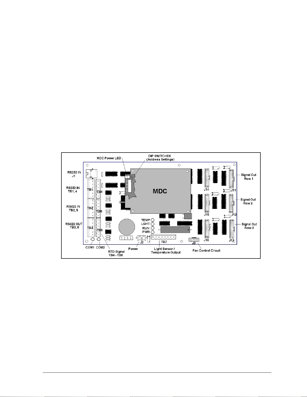
Controller
The controller sends data to the modules. Refer to the signal summary in Section 4.2 for more
information on the location of the controller board.
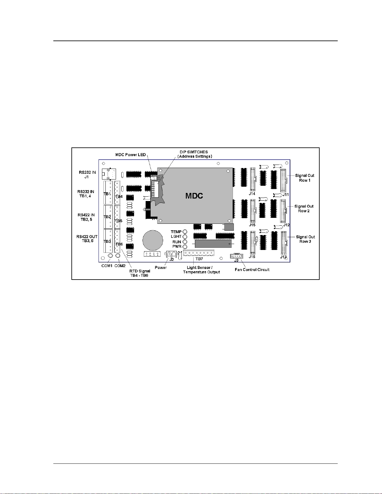
A typical controller is illus t rat ed in Figure 13 below.
Figure 13: Controller Component Layout
“DIP” switches are located on the controller’s MDC. These DIP switches set the hardware
address, which is used by the software to identify that particular sign. When replacing a controller
board, be sure to set the DIP switches in the same address configuration as the defect iv e
controller.
Note: Setting the DIP switches to address 0 (turn all the switches to OFF by flipping them toward
the printed switch numbers) can activate a test mode. The display’s power must be downed, and
then reconnected to run the test mode.
Maintenance and Troubleshooting 4-3
Page 24
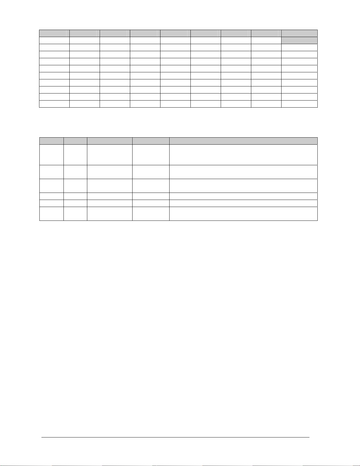
Switch 8 Switch 7 Switch 6 Switch 5 Switch 4 Switch 3 Switch 2 Switch 1 Address
Off Off Off Off Off Off Off Off
Off Off Off Off Off Off Off On
Off Off Off Off Off Off On Off
Off Off Off Off Off Off On On
Off Off Off Off Off On Off Off
Off Off Off Off Off On Off On
Off Off Off Off Off On On Off
Off Off Off Off Off On On On
… … … … … … … …
On On On On Off Off Off Off
Test Mode
1
2
3
4
5
6
7
…
240
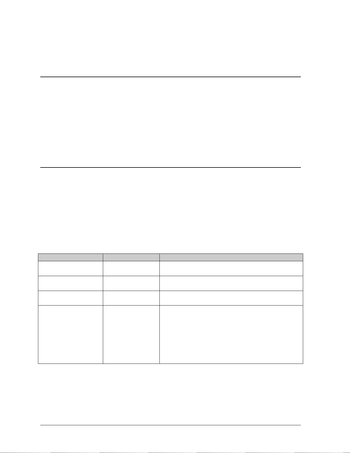
Four diagnostic LEDs are located on the controller. The following table explains what each LED
represents:
LED Color Function Operation Summary
TEMP Red Temperature
Level
LGHT Red Photocell Light
Level
RUN Red Controller Steady
PWR Green Power Always On Power to the data input circuit when lit.
RX1 Yellow Com 1 Flashes Turns on and flashes when receiving information.
RX2 Yellow Com 2 Flashes Turns on and flashes when receiving information,
Flashes Flash rate is dependent upon the temperature.
Flashes faster in high temperature and slows as the
temperature decreases.
Flashes Flash rate is dependent on the light level. Fl ashes
faster in bright light and slows as darkness descends.
A steady flash indicates the controller is running
Flash
correctly. Normal flash rate is about once a second.
typically used in custom applica tio ns .
Complete the following steps to remove this circuit board from the display:
1. Disconnect power from J2.
2. Remove all power and signal connections from the board. “Locked” connectors are released
by squeezing together the tabs, then carefully pulling them from the jack. When replacing the
board, it may be helpful if the cables are labeled as to which cable was removed from which
connector.
3. Remove each of the six screws holding the board in place.
4. Follow the previous steps in reverse order to install a new controller board.
If this board is being sent back to Daktronics keep any nuts, bolts or standoffs and immediately
place the board in a static bag.
Modules and Drivers
In most instances, the module and driver board can be addressed as a single functional unit. Every
module has a driver board mounted to its backside.
The LED power supplies are identified as assemblies (refer to Power Supplies on the following
page). Each power supply controls two modules; a single power supply assembly (one power
supply) controls two.
To remove a module, complete the following steps:
1. Locate the latch access fasteners on the module. One is centered below the top row of pixels
and one is above the bottom row.
2. With a 1/8" T-handle Allen wrench, turn the latch access fasteners a quarter turn. The top one
should be turned clockwise and the bottom one counter-clockwise.
4-4
Maintenance and Troubleshooting
Page 25

3. Pull the module of the sign far enough to reach around the back and disconnect the ribbon
cables.
When installing a module, reverse the previous steps and take note of the following points:
· The weather-stripping on the back edge of the module must be intact and in good condition if
it is to prevent water from seeping into the sign.
· The module latches must be fully engaged to create a watertight seal around the edge of the
module. The module should be firmly seated against the sign when the latches are fully
engaged.
Each module assembly is made up of a module housing (containing LEDs and the pc board) and a
louver assembly.
From time to time, it may become necessary to remove one or more parts from the module
housing for repair or replacement. The following sub-sections explain how to disassemble a
module.
Removing the Louver Assembly
Complete the following steps to remove the louver assembly from the face of the module:
1. Remove the five twist-on fasteners holding the louver assembly to the module, located on
the rear of the module.
2. Lift the louver assembly straight away from the module.
Damaged louvers may reduce the brightness and contrast of this sign. If any of the louvers on
the sign are broken or damaged, the entire louver assembly must be replaced. Refer to the
Replacement Parts List in Section 4.11. When replacing the louver assembly take care not to
strip the plastic twist-on fasteners.
Power Supplies
The LED power supplies are identified as assemblies earlier in the component location drawings.
Each power supply controls two modules; a power supply assembly controls four.
Complete the following steps to remove a power supply from the sign:
1. Remove the module directly in front of the failed power supply.
2. Disconnect all the wires connected to the power supply.
3. Remove the hardware holding the power supply in place to free the unit.
Follow these steps in reverse order to install a new power supply.
Maintenance and Troubleshooting 4-5
Page 26
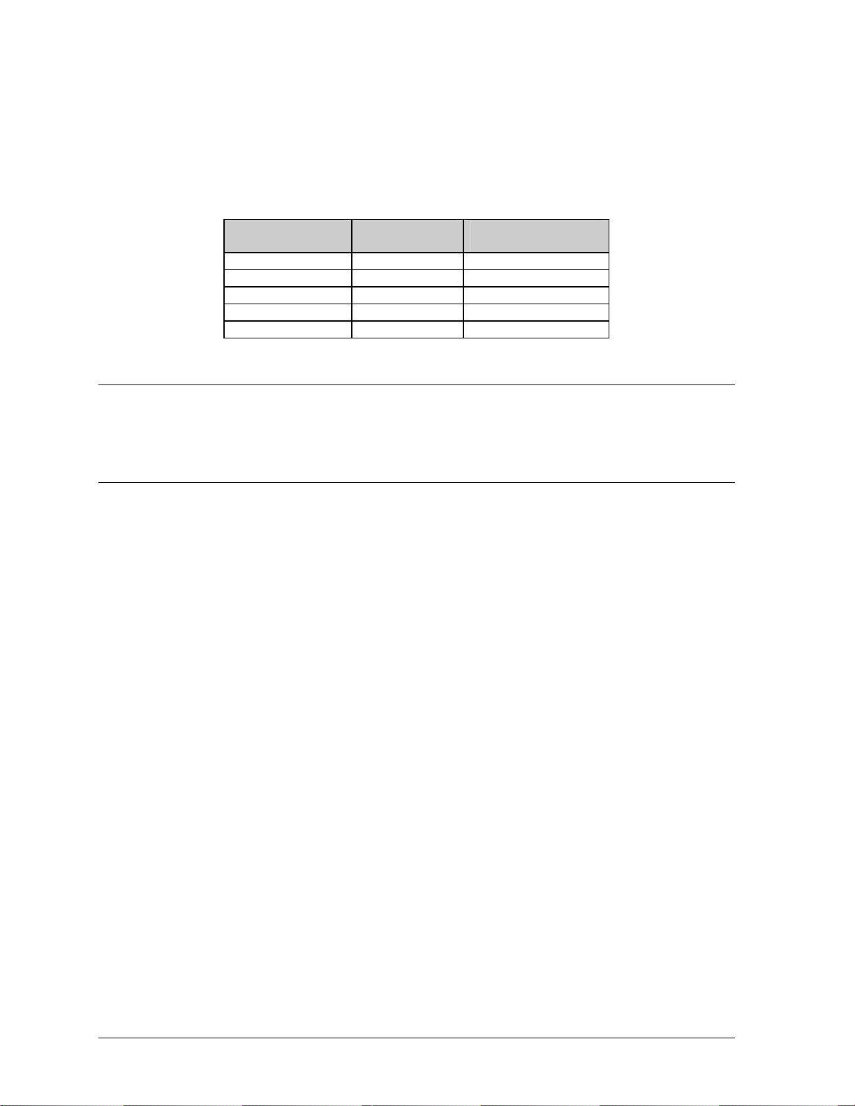
tLight De ector
The light detector is internally mounted and wired at Daktronics. It is located in the bottom left
corner on the front of the display (identified as assembly 0A-1215-4001 (LT)). A 4-conductor
cable is used to connect the light detector to the controller board. The cable is terminated at the
terminal block on the light sensor and at TB7 on the controller board (refer to Figure 13 on
page 4-6).
Light Detector
Pin No.
1 Green 3
2 White 4
3 Red 1
4 Black 2
N.C. Bare 2
Cable Wires
Color
Controller Board
Pin No.
4.5 Thermostats
A thermostat controls when the ventilation fans are turned on in the display and are located behind the
second top module (A102).
4.6 Ventilation Systems (With Fans and Filters)
Ventilation fans should be checked after 1,500 hours of operation and every 1,500 hours after that to
ensure the display is being cooled properly. Fans should be checked more often if the display is
located in a dusty or harsh weather environment (i.e. along a gravel road with dust laden air).
· 1,500 hours is equivalent to 83 days if the display is operated for 18 hours a day and the power to
the display is turned off when not in use.
1,500 hours is equivalent to 62 days if the display is running non-stop for 24 hours a day. ·
Attention: Power to the display should be shut off when the display is not in use. If the power is left
on when the display is not operating, the filters will require cleaning or replacement more often, and
electrical components will be exposed to excess condensation, which shortens their life.
Each time a module is removed, for whatever reason, take a minute to inspect the fans.
· Check the fan blades for dirt and debris. If the fan blades have a large accumulation of dirt and
debris, this indicates that the filters must be changed more often. Fan blades must be kept clean to
maintain fan efficiency and ensure proper cooling.
· Spin the fan blades with a pen or pencil to ensure that the bearings are free and the fan is still in
balance.
To check the operation of the fans:
· Hold your hand or a piece of light paper beneath the sign to detect air movement. If the operation
of a fan is questionable, a fan-testing power cord is available to check it.
· Plug the test cord into the fan and plug the other end into a 120-volt outlet.
· If the fan does not turn or does not operate smoothly, replace it.
Filters must be checked once a year or after every 1,500 hours of operation, whichever comes first.
Filters can be cleaned with water and a mild detergent, such as dish soap. Compressed air can also be
4-6
Maintenance and Troubleshooting
Page 27

used to clean the filters provided the nozzle is held at least six inches away from the filter, the pressure
is no greater than 60 psi and the air is blown through the filter in the opposite direction from which air
normally flows. The arrow stamped on the frame filter indicates airflow direction.
4.7 Galaxy Display Maintenance
A yearly inspection should be completed to maintain safe and dependable sign operation. This
inspection should address the following issues. If any of the following conditions are noticed, action
must be taken to correct the situation.
· Loose Hardware
Verify fasteners, such as bolts and rivets, have not come loose. Fasteners should be checked and
tightened or replaced as required.
· Excessive Dust Buildup
Occasionally it may be necessary to vacuum the inside of the sign cabinet to remove dust/dirt
buildup that may interfere with airflow.
· Water Intrusion – Water Stain Marks
Water can enter the sign where weather stripping has come loose or deteriorated or where
fasteners have come loose allowing gaps in the panels or where moisture may be entering around
hardware. Check electronic components for signs of corrosion.
· Corrosion
Check the paint and look for possible corrosion, especially at footings, structural tie points and
ground rods.
4.8 Weather Stripping
To ensure that the sign is waterproof, weather stripping has been provided around the entire sign and
around each module. It is important that the weather stripping is installed properly at all times or water
may leak into the sign and damage the components.
Maintenance and Troubleshooting 4-7
Page 28

4.9 Troubleshooting
This sub-section contains some symptoms that may be encountered in the signs. This list does not
include every possible symptom, but does represent common situations that may occur.
Symptom/Condition Possible Cause/Remedy
One or more LEDs on a single module fail
to light.
One or more LEDs on a single module fail
to turn off.
A section of the sign is not working. The
section extends all the way to the right side
of the sign.
One row of modules does not work or is
garbled.
A group of modules, which share the same
power supply assembly, fail to work.
Entire sign fails to work. · Check for proper line voltage into the power
Temperature always reads 32 degrees F/0
degrees C.
Sign is stuck on bright or dim. · Check Manual/Auto dimming in Venus 1500
· Replace/check ribbon cables on the module.
· Replace the module.
· Replace/check ribbon cables on module.
· Replace the module.
· Check/Replace the ribbon cable.
· Replace the first module/driver on the left side of the
first module that is not working.
· Replace the second module that is not working.
· Replace the power supply assembly on the first
module that is not working.
· Check/Replace the ribbon cable.
· Replace first module.
· Replace controller.
· Check the fuses in the power termination box.
· Replace the power supply assembly.
termination panel.
· Check/replace the signal cable to the controller.
· Check/replace the ribbon cable from the controller
to the modules.
· Check the voltage settings on the power supplies.
· Replace the controller.
· Verify proper use of the software in the operation
manual.
· Check temperature sensor connections.
· Replace the temperature sensor.
· Replace the controller.
software.
· Check light detector cable.
· Check light detector for obstructions.
· Replace the light detector.
· Replace the controller.
4.10 Initial Operation Information
When first operated, the sign will run through an initialization in which it will display the following:
1. Output Test (DDDs)
2. Product Name (Galaxy)
3. Sign Size (Row x Column)
4. Firmware Number (ED10134)
5. Firmware Revision (Rev X.XX)
6. COM1 Configuration (C1:
V15/RTD)
4-8
7. COM2 Configuration (C2: None)
8. Line Frequency (60 Hz)
9. Hardware Address (HW: XX)
10. Software Address (SW: XX)
11. Sign Name
12. Modem if Present (Modem)
Maintenance and Troubleshooting
Page 29

4.11 Replacement Parts List
The following table contains some of the items that may need to be replaced in this sign over a period
of time. Many of the parts within the sign also list their part numbers on labels affixed to them.
To prevent theft Daktronics recommends purchasing a lockable cabinet to store manuals and
replacement/spare parts.
Part Description Part Number
Controller II, 48x256, LED 0A-1146-0035
Red 20mm Module 0A-1266-2002
Amber 20mm Module 0A-1266-2003
Power Supply; 3 volt 0A-1289-4001
Power Supply; 3 volt 0A-1289-4002
Power Supply; 3 volt 0A-1289-4003
Power Supply; 3 volt 0A-1289-4004
Thermostat Enclosure 0A-1213-4024
Light Detector 0A-1215-4001
Cable; 40 POS 18" W-1412
Cable; 40 POS 36" W-1423
Cable; 18" RJ11 6 Cond 0A-1137-0160
Modem; 232, Coated 0P-1146-0003
Fiber 0P-1127-0024
TCP/IP 0A-1146-0063
RS232/422 Converter 0A-1127-0237
RS232/Fiber Converter 0A-1127-0239
4.12 Daktronics Exchange and Repair and Return Programs
To serve customers' repair and maintenance needs, Daktronics offers both an Exchange Program and a
Repair and Return Program.
Daktronics' unique Exchange Program is a quick, economical service for replacing key components in
need of repair. If a component fails, Daktronics sends the customer a replacement, and the customer,
in turn, sends the failed component to Daktronics. This not only saves money but also decreases
display downtime.
Daktronics provides these plans to ensure users get the most from their Daktronics products, and it
offers the service to qualified customers who follow the program guidelines explained below. Please
call the Help Desk – 877-605-1113 – if you have questions regarding the Exchange Program or any
other Daktronics service.
When you call the Help Desk, a trained service technician will work with you to solve the equipment
problem. You will work together to diagnose the problem and determine which replacement part to
ship. If, after you make the exchange, the equipment still causes problems, please contact our Help
Desk immediately.
If the replacement part fixes the problem, package the defective part in the same box and wrapping in
which the replacement part arrived, fill out and attach the enclosed UPS shipping document, and
return the part to Daktronics. In most circumstances, you will be invoiced for the replacement part
at the time it is shipped. This bill, which represents the exchange price, is due when you receive it.
Maintenance and Troubleshooting 4-9
Page 30

Daktronics expects immediate return of an exchange part if it does not solve the problem. The
company also reserves the right to refuse equipment that has been damaged due to acts of nature or
causes other than normal wear and tear.
If you do not ship the defective equipment Daktronics within 30 working days from the invoice date,
Daktronics assumes you are purchasing the replacement part outright (with no exchange), and you will
be invoiced for it. This second invoice represents the difference between the exchange price and the
full purchase price of the equipment. The balance is due when you receive the second invoice.
If you return the exchange equipment after 30 working days from the invoice date, you will be
credited for the amount on the second invoice, minus a restocking fee. To avoid a restocking charge,
you must return the defective equipment within 30 days from the invoice date.
Daktronics also offers a Repair and Return Program for items not subject to exchange.
Return Materials Authorization: To return parts for service, contact your local representative prior
to shipment to acquire a Return Material Authorization (RMA) number. If you do not have a local
representative, call the Daktronics Help Desk for the RMA. This expedites repair of your component
when it arrives at Daktronics.
Packaging for Return: Package and pad the item well so that it will not be damaged in shipment.
Electronic components such as printed circuit boards should be installed in an enclosure or placed in
an antistatic bag before boxing. Please enclose your name, address, phone number and a clear
description of symptoms.
This is how to reach us:
Mail: Customer Service, Daktronics Inc.
PO Box 5128
331 32nd Ave
Brookings SD 57006
Phone: Daktronics Help Desk: 877-605-1113 (toll free)
or 605-697-4034
Fax: 605-697-4444
E-mail: helpdesk@daktronics.com
4-10 Maintenance and Troubleshooting
Page 31

Appendix A: Reference Drawings
Refer to Section 1.1 for information on reading drawing numbers. The following drawings are listed
by type of drawing and then by size of display.
Temp Sensor Mounting............................................................................... Drawing A- 79767
System Riser Diagram, Modem...................................................................Drawing A-88426
System Riser Diagram; Pwr & Sig V1500 Displays ..................................... Drawing A-88427
System Riser Diagram, RS422....................................................................Drawing A-92681
System Riser Diagram, RS232....................................................................Drawing A-96058
Power Termination Box Assembly...............................................................Drawing A-99785
System Riser Diagram; Fiber.................................................................... Drawing A-110559
Power Termination Box.............................................................................Drawi ng A-129227
Assy, Harn Phoenix Connector 6 Position to RJ/45................................... Drawing A-140596
System Riser Diagram, RS422, Local Control...........................................Drawing A-160685
V1500; TCP/IP (UDS-10) System Riser Diagram...................................... Drawing A-170417
System Riser Diagram, LED Display, Fiber............................................... Drawing A- 177569
Schematic, AF-3050-16x64-R...................................................................Drawing B-166368
Schematic, AF-3050-16x80-20mm............................................................Drawing B-168173
Schematic, AF-3050-16x96-20mm............................................................Drawing B-177974
Schematic, AF-3050-16x112-20mm..........................................................Drawing B-169469
Schematic, AF-3050-16x224-20mm..........................................................Drawing B-171246
Schematic, AF-3050-16x448-20mm..........................................................Drawing B-171256
Schematic, AF-3050-32x64-6, R............................................................... Draw ing B-157299
Schematic, AF-3050-32x80-20mm............................................................Drawing B-171415
Schematic, AF-3050-32x96-A, Monochrome............................................. Drawing B-166161
Schematic, AF-3050-32x96-20mm............................................................Drawing B-178860
Schematic, AF-3050-32x112-6, RG...........................................................Drawing B-162500
Schematic; AE-3050-32120-2.1-R-DF....................................................... Drawing B-129003
Schematic, AF-3050-32x144-20mm..........................................................Drawing B-174437
Schematic, AF-3050-32x208-6, Monochrome ...........................................Drawing B-160458
Schematic, AF-3050-48x96-20mm............................................................Drawing B-173481
Schematic, AF-3050-48x144-20mm..........................................................Drawing B-174368
Schematic, AF-3050-48x240-20mm..........................................................Drawing B-177501
Schematic, AF-3050-64x240-20mm..........................................................Drawing B-171269
Schematic; Power Supply Configurations.................................................. Drawing A-126330
Comp. Layout Diagram, AF-3050-1664-20................................................Drawing A-179430
Comp. Layout Diagram, AF-3050-1680-20................................................Drawing A-168206
Comp. Layout Diagram, AF-3050-1696-20-R ............................................ Drawing A-178829
Comp. Layout Diagram, AF-3050-16112-20-R..........................................Drawing A-169016
Comp. Layout Diagram, AF-3050-16224-20.............................................. Draw ing A-171407
Comp. Layout Diagram, AF-3050-16448-20.............................................. Draw ing A-171433
Component Layout Diagram, AF-3050-3264-23-R-WAL........................... Drawing A-157311
Comp, Layout Diagram, AF-3050-3280-20................................................Drawing A-176203
Comp, Layout Diagram, AF-3050-3280-20................................................Drawing A-171113
Comp. Layout Diagram, AF-3050-3296-20................................................Drawing A-178803
Appendix A: Reference Drawings
A-1
Page 32

Comp. Layout Diagram, AF-3050-32144-20-A.......................................... Drawing A-174299
Comp. Layout Diagram, AF-3050-32144-20..............................................Drawing B-178219
Comp. Layout Diagram, AF-3050-32208-23-A.......................................... Drawing A-160769
Comp. Layout Diagram, AF-3050-32208-23-A.......................................... Drawing A-161368
Comp. Layout Diagram, AF-3050-4896-20................................................Drawing A-173812
Comp. Layout Diagram, AF-3050-48144-20.............................................. Draw ing A-174010
Comp. Layout Diagram, AF-48128-20....................................................... Draw ing A-177539
Comp. Layout Diagram, AF-3050-64240-20-A.......................................... Drawing A-171408
Comp. Layout Diagram............................................................................. Drawing A-166183
Final Assembly, 16x16 MOD..................................................................... Drawing B-154306
F. Assy, AF-3050-1680-20........................................................................ Drawing A-168205
F. Assy, AF-3050-16112-20...................................................................... Drawing A-169692
F. Assy, AF-3050-3264-23-R.................................................................... Drawing A-157621
F. Assy, AF-3050-3280-20-A.....................................................................Drawing A-171523
F. Assy, AF-3050-3296-23-A.....................................................................Drawing A-166245
Final Assy, AE-3050-32120-2.1, St raight Face.......................................... Drawing B-131889
Final Assy, AE-3050-32120-2.1 , Tilted Face............................................. Drawing B-132031
Final Assy, AF-3050-32208-23.................................................................. Draw ing A-160728
Final Assembly, 20mm Module .................................................................Drawing B-158671
Shop Drawing, AF-3050-1664-20-A.......................................................... Drawing B-179428
Shop Drawing, AF-3050-1680-R............................................................... Drawing B-173201
Shop Drawing, AF-3050-1680-20-R.......................................................... Drawing B-179425
Shop Drawing, AF-3050-1696-20-A.......................................................... Drawing B-176334
Shop Drawing, AF-3050-16112-20-A........................................................ Drawing B-172615
Shop Drawing, AF-3050-16112-20............................................................ Drawing B-168885
Shop Drawing, AF-3050-16224-20-A........................................................ Drawing B-170473
Shop Drawing, AF-3050-16448-20-A........................................................ Drawing B-170481
Shop Drawing, AF-3050-3264-6-R............................................................Drawi ng B-147590
Shop Drawing, AF-3050-32x80-20-A........................................................ Drawing B-171057
Shop Drawing, AF-3050-3280-20-R.......................................................... Drawing B-176284
Shop Drawing, AF-3050-3296-23-A.......................................................... Drawing B-165852
Shop Drawing, AF-3050-3296-20.............................................................. Drawing B-176307
Shop Drawing, AF-3050-32112-20............................................................ Drawing B-176400
Shop Drawing, AF-3050-32144-20............................................................ Drawing B-176288
Shop Drawing, AE-3050-32x120-2.1, DF.................................................. Drawing B-113557
Shop Drawing, AE-3050-32x120-2.1, DSLANT......................................... Drawing B-116640
Shop Drawing, AF-3050-32144-20-A........................................................ Drawing B-174520
Shop Drawing, AF-3050-32208-6-A.......................................................... Drawing B-159062
Shop Drawing, AF-3050-4896-20-A.......................................................... Drawing B-173749
Shop Drawing, AF-3050-48144-20-A........................................................ Drawing B-173823
Shop Drawing, AF-3050-48240-20-A........................................................ Drawing B-177427
Shop Drawing, AF-3050-64240-20-A........................................................ Drawing B-171101
A-2 Appendix A: Reference Drawings
Page 33

Page 34

Page 35

Page 36

Page 37

Page 38

Page 39

Page 40

Page 41

Page 42

Page 43

Page 44

Page 45

Page 46

Page 47

Page 48

Page 49

Page 50

Page 51

Page 52

Page 53

Page 54

Page 55

Page 56

Page 57

Page 58

Page 59

Page 60

Page 61

Page 62

Page 63

Page 64

Page 65

Page 66

Page 67

Page 68

Page 69

Page 70

Page 71

Page 72

Page 73

Page 74

Page 75

Page 76

Page 77

Page 78

Page 79

Page 80

Page 81

Page 82

Page 83

Page 84

Page 85

Page 86

Page 87

 Loading...