

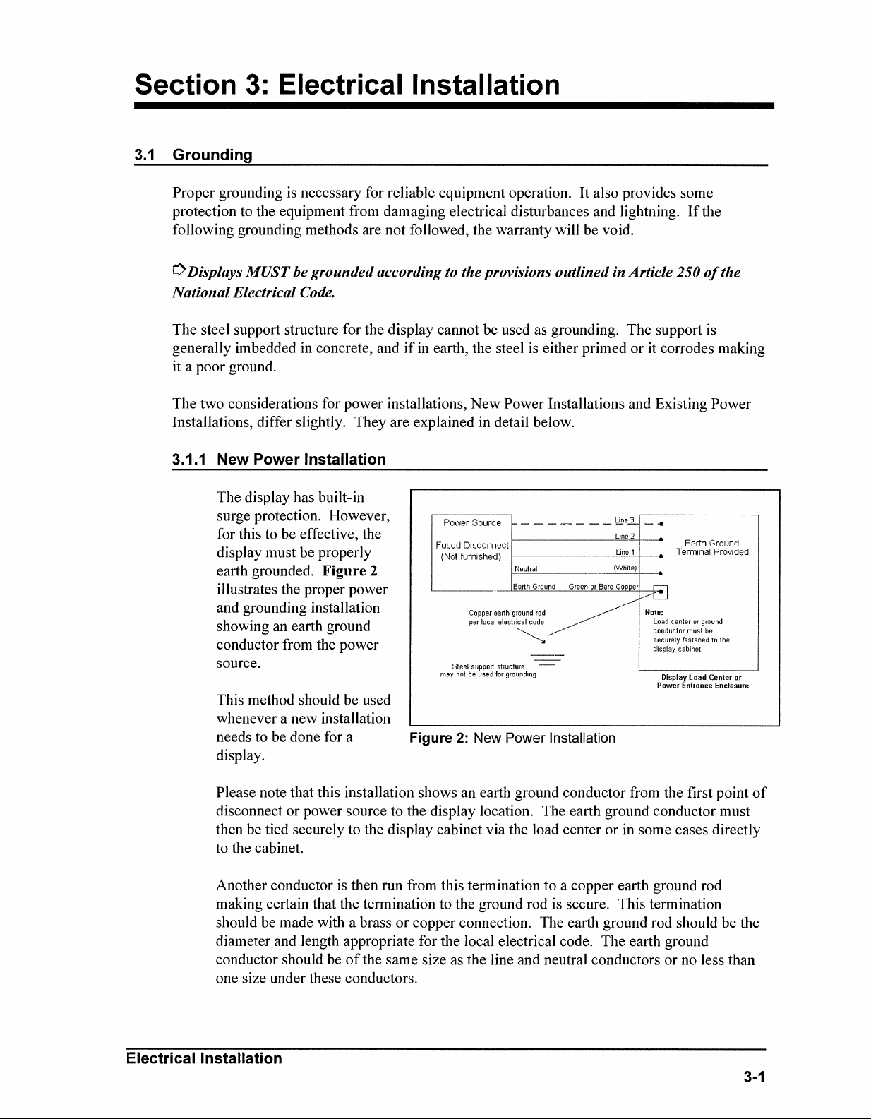
Page 1
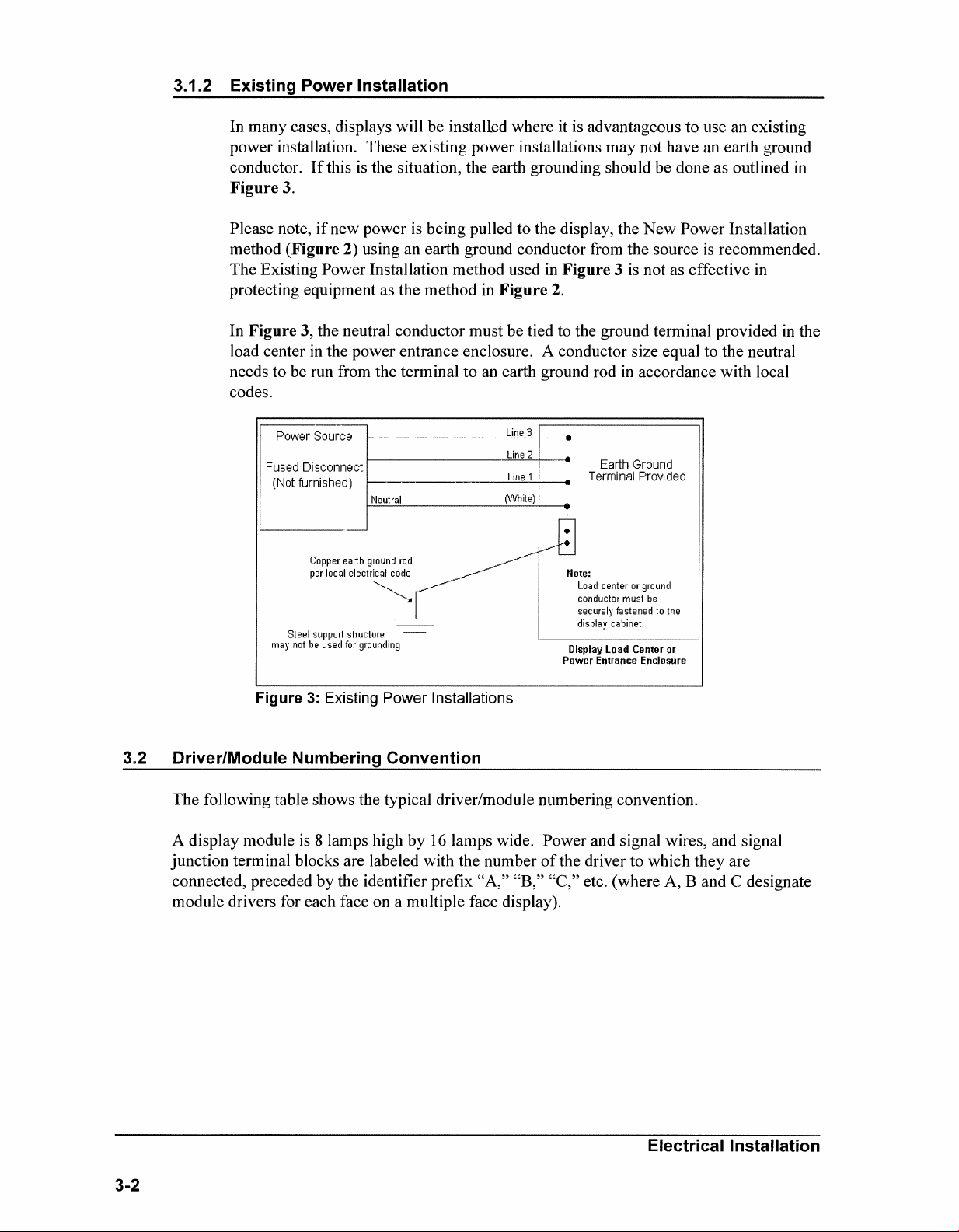
Page 2

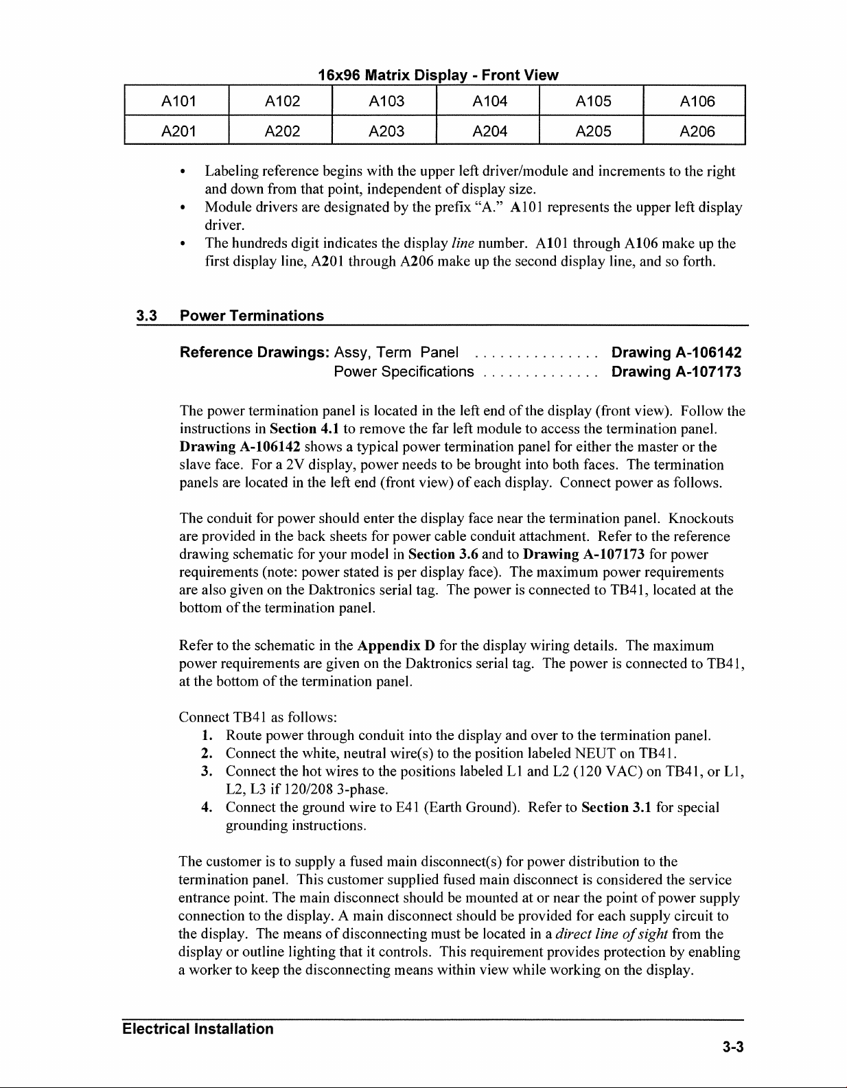
Page 3
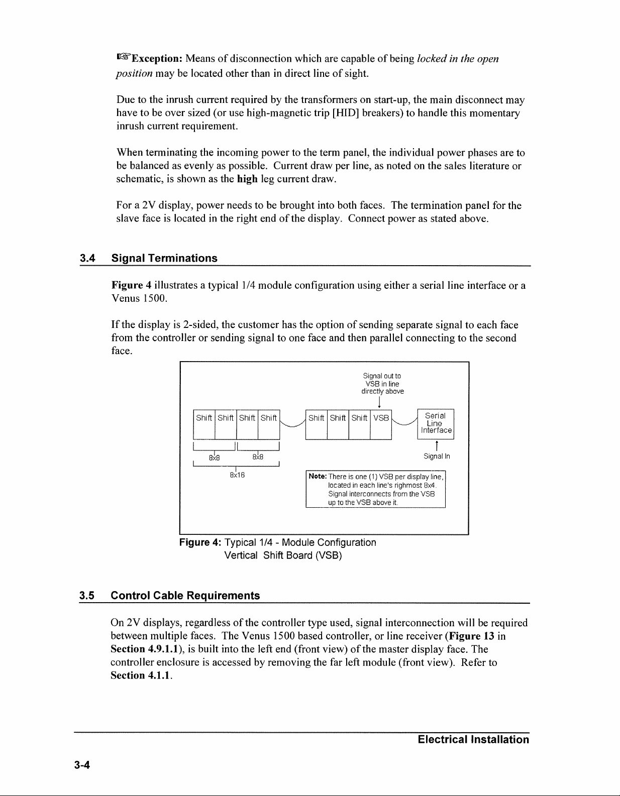
Page 4
Page 5
Page 6

Page 7

Page 8
Page 9
Page 10
Page 11
Page 12
Page 13
Page 14
Page 15
Page 16
Page 17
Page 18
Page 19
Page 20
Page 21
Page 22
Page 23
Page 24
Page 25
Page 26
Page 27

Page 28

Page 29

Page 30

Page 31

Page 32

Page 33

Page 34

Page 35

Page 36

Page 37

Page 38

Page 39

Page 40

Page 41

Page 42

Page 43

Page 44

Page 45

Page 46

Page 47

Page 48

Page 49

Page 50

Page 51

Page 52

Page 53

Page 54

Page 55

Page 56

Page 57

Page 58

Page 59

Page 60

Page 61

Page 62

Page 63

The Temperature Sensor is mounted separately and requires a location away from the influence of
chimneys, air conditioners, vents, tar roofs, concrete, and parking lots which can cause abnormal
temperature fluctuations. Usually a separation of at least 20-30 feet horizontally and 8 feet vertically is
required to achieve this. Locations where air movement is restricted are also unsatisfactory.
A first-choice sensor location is a north eave or northern exposure away from direct sun light and above
grass. This location gives extra stability and accuracy to the sensor because of the added shading usually
obtained on a northern exposure.
The second choice for locating a temperature sensor is on the display itself, or somewhere on the display
structure. A light-colored display is preferred in this application. Location of the sensor should be above,
below, or on a northern edge of the display to try to keep the sensor shaded. If mounting above the
display, a minimum height above of 6 feet is required. If mounting below the display, a minimum of 8 feet
above ground and a minimum of 1 foot between sensor and display is required. Greater accuracy is
obtained if there is grass below the sign rather than concrete or some other material.
A 2 pair, individually shielded cable (Belden 5594, Dak. P.N. W-1234) is used to connect the sensor to the
display controller. Maximum length is 1000 feet.
Directions
1. Run ½" conduit from the sensor location to the controller where the sensor cable is to be attached.
The cable must be routed thru ½" metal conduit which should be earth grounded to help protect
the sensor and controller from lightning damage.
2. Power down the controller where the sensor cable is to be attached.
3. Connect the cable to the temperature sensor terminal block as follows:
RED = V+ BLK = GND
GRN = P WHT = N
4. Install the mesh screen with the four screws enclosed.
5. Connect the cable to the display controller as described in the controller installation manual.
6. Power up the controller.
Page 64

Page 65

Page 66

Page 67

Eyebolts
Almost every display that leav es D ak tronics is equipped w ith ey ebolts for lifting the display . There are
two standard sizes of eyebolts: ½″ and A″.
Load Increase Factor: The load increases as the lift angle (θ) decreases. The allowable load on the
eyebolts also decreases with the lift angle due the bending stress on the eyebolts. In sum, the smaller
the angle between the cable and the top of the display, the lighter the sign must be to safely lift it. Do
NOT attempt to lift the display when the lift angle is less than 30 degrees.
Horizontal Load Angle
Angle Factor (L/H)
90 1.00
60 1.155 90 2600 2600 4000 4000
50 1.305 60 1500 1299 3300 2858
45 1.414 45 650 460 1000 707
30 2.00 30 520 260 800 400
θθθθ
½”
Line Weight/ Line Weight/
Load Anchor Load Anchor
A
A”
AA
ED7244 Copyright 1996-2001
Rev. 4 – 14 March 2001 Daktronics, Inc.
Page 68

Min.
A B C D E No.
Wx Wy Wz
1/4 1 3/4 1-3/16 25/32 21 600 2,000 Blank 1/4-20 7/8 400 100 80
3/8 1-1/4 1 1-21/32 1-3/16 23 2,100 5,000 Blank 3/8-16 1-1/8 1,400 350 250
1/2 1-1/2 1-3/16 2-1/16 1-13/32 25 3,900 9,200 Blank 1/2-13 1-11/32 2,600 650 520
9/16 1-5/8 1-9/32 2-13/16 1-17/32 26 4,500 11,830 Blank 9/16-12 1-3/8 3,000 750 600
5/8 1-3/4 1-3/8 2-1/2 1-11/16 27 6,000 14,700 Blank 5/8-11 1-9/16 4,000 1,000 800
3/4 2 1-1/2 2-13/16 1-13/16 28 9,000 21,700 Blank 3/4-10 1-5/8 6,000 1,500 1,200
7/8 2-1/4 1-11/16 3-1/4 2-1/16 29 10,000 30,000 Blank 7/8-9 1-13/16 6,600 1,670 1,330
1 2-1/2 1-13/16 3-9/16 2-5/16 30 12,000 39,400 Blank 1-8 2-1/16 8,000 2,000 1,600
1-1/2 3-1/2 2-9/16 5-1/2 3-5/32 34 27,000 91,300 Blank 1-1/2-6 3 17,800 4,500 3,600
Proof
Load
(lbs.)
Min.
Break
Load
(lbs.)
Stocked
Min.
Eff.
Thrd.
Length
Line Loads
A. Do not use eyebolts on angular lifts unless absolutely necessary. For angular lifts, the shoulder pattern
eyebolt is preferred.
B. Load should always be applied to eyebolts in the plane of the eye, not at some angle to this plane.
C. Shoulder eyebolts must be properly seated (should bear firmly against the mating part), otherwise the
working loads must be reduced to those indicated for regular eyebolts. A washer or spacer may be
required to put the plane of the eye in the direction of the load when the shoulder is seated.
D. No load greater than the safe working load listed in the data table should be used.
E. To obtain the greatest strength from the eyebolt, it must fit reasonably tight in its mounting hole to prevent
accidental unscrewing due to twist of cable.
F. Eyebolts should never be painted or otherwise coated when used for lifting. Such coatings may cover
potential flaws in the eyebolt.
G. To attain the safe working loads listed for regular eyebolts, 90% of the thread length must be engaged.
Copyright 1996-2001 ED-7244
Daktronics, Inc. Rev. 4 – 14 March 2001
Page 69

Page 70

Maintenance Checklist
1½ Inch and 2½ Inch Displays
This form can be used as both as a maintenance guide and a record of maintenance performed. Store these forms in
maintenance file as they are completed. Each form is designed to cover one year of maintenance.
Circle the operational year to which this form applies 1 2 3 4 5 6 7 8 9 10
Maintenance Procedures
1. Check fans at 1,500 hour intervals to ensure proper operation. With display power off, clean dust from blades and
spin the blades with a pen or pencil to make sure the bearings are free and the fan is still 'in balance.
2. Check the filters at 1,500 hour intervals. Check the filter for excessive dust/dirt buildup and for damage, such as
holes, which may allow unfiltered air into the display.
3. Check line and lamp voltage every 4,500 hours or whenever a significant change occurs in the area that could
affect line voltage. Refer to the Electrical Installation section of the Installation and Maintenance Manual for more
information.
4. At least once each 9,000 operational hours check the inside of the display, including the circuit boards, for signs of
water intrusion such as water stains. Water may enter the display due to any of the following:
• Loose or deteriorating weather stripping.
• Loosened fasteners which allow gaps to open between panels.
• Weak seals around hardware, such as eye bolts, on the top of the display.
5. At least once each 9,00 operational hours inspect the paint and check for signs of corrosion on the structure. Pay
special attention to footings, structural tie points and ground rods. Fasteners should be tightened or replaced as
required.
Operation Hours Perform Above
Steps Numbered
1,500 Hrs
3,000 Hrs
4,500 Hrs
6,000 Hrs
7,500 Hrs
9,500 Hrs
* Day 83
* Day 62
* Day 166
** Day 125
* Day 249
** Day 187
* Day 332
** Day 250
* Day 415
** Day 312
* Day 498
** Day 365
1,2
1,2
1,2,3
1,2
1,2
1,2,3,4,5
* Assuming the display is operated 18 hours per day
and is turned off when not in use.
** Assuming the display is operated 24 hours per day.
Consult the Installation and Maintenance Manual for additional
Maintenance Details.
Date Performed Checked By
DF-1866
Rev. 3 – 24 October 2001
DAKTRONICS, INC.
P.O. Box 5128 331 32nd Ave. Brookings, SD 57006
Phone (605) 697-4035 or (877) 605-1114 Fax (605) 697-4444
www.daktronics.com e-mail helpdesk@daktronics.com
Page 71

Maintenance Checklist
1½ Inch and 2½ Inch Displays
This form can be used as both as a maintenance guide and a record of maintenance performed. Store these forms in
maintenance file as they are completed. Each form is designed to cover one year of maintenance.
Circle the operational year to which this form applies 1 2 3 4 5 6 7 8 9 10
Maintenance Procedures
1. Check fans at 1,500 hour intervals to ensure proper operation. With display power off, clean dust from blades and
spin the blades with a pen or pencil to make sure the bearings are free and the fan is still 'in balance.
2. Check the filters at 1,500 hour intervals. Check the filter for excessive dust/dirt buildup and for damage, such as
holes, which may allow unfiltered air into the display.
3. Check line and lamp voltage every 4,500 hours or whenever a significant change occurs in the area that could
affect line voltage. Refer to the Electrical Installation section of the Installation and Maintenance Manual for more
information.
4. At least once each 9,000 operational hours check the inside of the display, including the circuit boards, for signs of
water intrusion such as water stains. Water may enter the display due to any of the following:
• Loose or deteriorating weather stripping.
• Loosened fasteners which allow gaps to open between panels.
• Weak seals around hardware, such as eye bolts, on the top of the display.
5. At least once each 9,00 operational hours inspect the paint and check for signs of corrosion on the structure. Pay
special attention to footings, structural tie points and ground rods. Fasteners should be tightened or replaced as
required.
Operation Hours Perform Above
Steps Numbered
1,500 Hrs
3,000 Hrs
4,500 Hrs
6,000 Hrs
7,500 Hrs
9,500 Hrs
* Day 83
* Day 62
* Day 166
** Day 125
* Day 249
** Day 187
* Day 332
** Day 250
* Day 415
** Day 312
* Day 498
** Day 365
1,2
1,2
1,2,3
1,2
1,2
1,2,3,4,5
* Assuming the display is operated 18 hours per day
and is turned off when not in use.
** Assuming the display is operated 24 hours per day.
Consult the Installation and Maintenance Manual for additional
Maintenance Details.
Date Performed Checked By
DF-1866
Rev. 3 – 24 October 2001
DAKTRONICS, INC.
P.O. Box 5128 331 32nd Ave. Brookings, SD 57006
Phone (605) 697-4035 or (877) 605-1114 Fax (605) 697-4444
www.daktronics.com e-mail helpdesk@daktronics.com
Page 72

Maintenance Checklist
1½ Inch and 2½ Inch Displays
This form can be used as both as a maintenance guide and a record of maintenance performed. Store these forms in
maintenance file as they are completed. Each form is designed to cover one year of maintenance.
Circle the operational year to which this form applies 1 2 3 4 5 6 7 8 9 10
Maintenance Procedures
1. Check fans at 1,500 hour intervals to ensure proper operation. With display power off, clean dust from blades and
spin the blades with a pen or pencil to make sure the bearings are free and the fan is still 'in balance.
2. Check the filters at 1,500 hour intervals. Check the filter for excessive dust/dirt buildup and for damage, such as
holes, which may allow unfiltered air into the display.
3. Check line and lamp voltage every 4,500 hours or whenever a significant change occurs in the area that could
affect line voltage. Refer to the Electrical Installation section of the Installation and Maintenance Manual for more
information.
4. At least once each 9,000 operational hours check the inside of the display, including the circuit boards, for signs of
water intrusion such as water stains. Water may enter the display due to any of the following:
• Loose or deteriorating weather stripping.
• Loosened fasteners which allow gaps to open between panels.
• Weak seals around hardware, such as eye bolts, on the top of the display.
5. At least once each 9,00 operational hours inspect the paint and check for signs of corrosion on the structure. Pay
special attention to footings, structural tie points and ground rods. Fasteners should be tightened or replaced as
required.
Operation Hours Perform Above
Steps Numbered
1,500 Hrs
3,000 Hrs
4,500 Hrs
6,000 Hrs
7,500 Hrs
9,500 Hrs
* Day 83
* Day 62
* Day 166
** Day 125
* Day 249
** Day 187
* Day 332
** Day 250
* Day 415
** Day 312
* Day 498
** Day 365
1,2
1,2
1,2,3
1,2
1,2
1,2,3,4,5
* Assuming the display is operated 18 hours per day
and is turned off when not in use.
** Assuming the display is operated 24 hours per day.
Consult the Installation and Maintenance Manual for additional
Maintenance Details.
Date Performed Checked By
DF-1866
Rev. 3 – 24 October 2001
DAKTRONICS, INC.
P.O. Box 5128 331 32nd Ave. Brookings, SD 57006
Phone (605) 697-4035 or (877) 605-1114 Fax (605) 697-4444
www.daktronics.com e-mail helpdesk@daktronics.com
Page 73

Maintenance Checklist
1½ Inch and 2½ Inch Displays
This form can be used as both as a maintenance guide and a record of maintenance performed. Store these forms in
maintenance file as they are completed. Each form is designed to cover one year of maintenance.
Circle the operational year to which this form applies 1 2 3 4 5 6 7 8 9 10
Maintenance Procedures
1. Check fans at 1,500 hour intervals to ensure proper operation. With display power off, clean dust from blades and
spin the blades with a pen or pencil to make sure the bearings are free and the fan is still 'in balance.
2. Check the filters at 1,500 hour intervals. Check the filter for excessive dust/dirt buildup and for damage, such as
holes, which may allow unfiltered air into the display.
3. Check line and lamp voltage every 4,500 hours or whenever a significant change occurs in the area that could
affect line voltage. Refer to the Electrical Installation section of the Installation and Maintenance Manual for more
information.
4. At least once each 9,000 operational hours check the inside of the display, including the circuit boards, for signs of
water intrusion such as water stains. Water may enter the display due to any of the following:
• Loose or deteriorating weather stripping.
• Loosened fasteners which allow gaps to open between panels.
• Weak seals around hardware, such as eye bolts, on the top of the display.
5. At least once each 9,00 operational hours inspect the paint and check for signs of corrosion on the structure. Pay
special attention to footings, structural tie points and ground rods. Fasteners should be tightened or replaced as
required.
Operation Hours Perform Above
Steps Numbered
1,500 Hrs
3,000 Hrs
4,500 Hrs
6,000 Hrs
7,500 Hrs
9,500 Hrs
* Day 83
* Day 62
* Day 166
** Day 125
* Day 249
** Day 187
* Day 332
** Day 250
* Day 415
** Day 312
* Day 498
** Day 365
1,2
1,2
1,2,3
1,2
1,2
1,2,3,4,5
* Assuming the display is operated 18 hours per day
and is turned off when not in use.
** Assuming the display is operated 24 hours per day.
Consult the Installation and Maintenance Manual for additional
Maintenance Details.
Date Performed Checked By
DF-1866
Rev. 3 – 24 October 2001
DAKTRONICS, INC.
P.O. Box 5128 331 32nd Ave. Brookings, SD 57006
Phone (605) 697-4035 or (877) 605-1114 Fax (605) 697-4444
www.daktronics.com e-mail helpdesk@daktronics.com
Page 74

Maintenance Checklist
1½ Inch and 2½ Inch Displays
This form can be used as both as a maintenance guide and a record of maintenance performed. Store these forms in
maintenance file as they are completed. Each form is designed to cover one year of maintenance.
Circle the operational year to which this form applies 1 2 3 4 5 6 7 8 9 10
Maintenance Procedures
1. Check fans at 1,500 hour intervals to ensure proper operation. With display power off, clean dust from blades and
spin the blades with a pen or pencil to make sure the bearings are free and the fan is still 'in balance.
2. Check the filters at 1,500 hour intervals. Check the filter for excessive dust/dirt buildup and for damage, such as
holes, which may allow unfiltered air into the display.
3. Check line and lamp voltage every 4,500 hours or whenever a significant change occurs in the area that could
affect line voltage. Refer to the Electrical Installation section of the Installation and Maintenance Manual for more
information.
4. At least once each 9,000 operational hours check the inside of the display, including the circuit boards, for signs of
water intrusion such as water stains. Water may enter the display due to any of the following:
• Loose or deteriorating weather stripping.
• Loosened fasteners which allow gaps to open between panels.
• Weak seals around hardware, such as eye bolts, on the top of the display.
5. At least once each 9,00 operational hours inspect the paint and check for signs of corrosion on the structure. Pay
special attention to footings, structural tie points and ground rods. Fasteners should be tightened or replaced as
required.
Operation Hours Perform Above
Steps Numbered
1,500 Hrs
3,000 Hrs
4,500 Hrs
6,000 Hrs
7,500 Hrs
9,500 Hrs
* Day 83
* Day 62
* Day 166
** Day 125
* Day 249
** Day 187
* Day 332
** Day 250
* Day 415
** Day 312
* Day 498
** Day 365
1,2
1,2
1,2,3
1,2
1,2
1,2,3,4,5
* Assuming the display is operated 18 hours per day
and is turned off when not in use.
** Assuming the display is operated 24 hours per day.
Consult the Installation and Maintenance Manual for additional
Maintenance Details.
Date Performed Checked By
DF-1866
Rev. 3 – 24 October 2001
DAKTRONICS, INC.
P.O. Box 5128 331 32nd Ave. Brookings, SD 57006
Phone (605) 697-4035 or (877) 605-1114 Fax (605) 697-4444
www.daktronics.com e-mail helpdesk@daktronics.com
Page 75

Maintenance Checklist
1½ Inch and 2½ Inch Displays
This form can be used as both as a maintenance guide and a record of maintenance performed. Store these forms in
maintenance file as they are completed. Each form is designed to cover one year of maintenance.
Circle the operational year to which this form applies 1 2 3 4 5 6 7 8 9 10
Maintenance Procedures
1. Check fans at 1,500 hour intervals to ensure proper operation. With display power off, clean dust from blades and
spin the blades with a pen or pencil to make sure the bearings are free and the fan is still 'in balance.
2. Check the filters at 1,500 hour intervals. Check the filter for excessive dust/dirt buildup and for damage, such as
holes, which may allow unfiltered air into the display.
3. Check line and lamp voltage every 4,500 hours or whenever a significant change occurs in the area that could
affect line voltage. Refer to the Electrical Installation section of the Installation and Maintenance Manual for more
information.
4. At least once each 9,000 operational hours check the inside of the display, including the circuit boards, for signs of
water intrusion such as water stains. Water may enter the display due to any of the following:
• Loose or deteriorating weather stripping.
• Loosened fasteners which allow gaps to open between panels.
• Weak seals around hardware, such as eye bolts, on the top of the display.
5. At least once each 9,00 operational hours inspect the paint and check for signs of corrosion on the structure. Pay
special attention to footings, structural tie points and ground rods. Fasteners should be tightened or replaced as
required.
Operation Hours Perform Above
Steps Numbered
1,500 Hrs
3,000 Hrs
4,500 Hrs
6,000 Hrs
7,500 Hrs
9,500 Hrs
* Day 83
* Day 62
* Day 166
** Day 125
* Day 249
** Day 187
* Day 332
** Day 250
* Day 415
** Day 312
* Day 498
** Day 365
1,2
1,2
1,2,3
1,2
1,2
1,2,3,4,5
* Assuming the display is operated 18 hours per day
and is turned off when not in use.
** Assuming the display is operated 24 hours per day.
Consult the Installation and Maintenance Manual for additional
Maintenance Details.
Date Performed Checked By
DF-1866
Rev. 3 – 24 October 2001
DAKTRONICS, INC.
P.O. Box 5128 331 32nd Ave. Brookings, SD 57006
Phone (605) 697-4035 or (877) 605-1114 Fax (605) 697-4444
www.daktronics.com e-mail helpdesk@daktronics.com
Page 76

Maintenance Checklist
1½ Inch and 2½ Inch Displays
This form can be used as both as a maintenance guide and a record of maintenance performed. Store these forms in
maintenance file as they are completed. Each form is designed to cover one year of maintenance.
Circle the operational year to which this form applies 1 2 3 4 5 6 7 8 9 10
Maintenance Procedures
1. Check fans at 1,500 hour intervals to ensure proper operation. With display power off, clean dust from blades and
spin the blades with a pen or pencil to make sure the bearings are free and the fan is still 'in balance.
2. Check the filters at 1,500 hour intervals. Check the filter for excessive dust/dirt buildup and for damage, such as
holes, which may allow unfiltered air into the display.
3. Check line and lamp voltage every 4,500 hours or whenever a significant change occurs in the area that could
affect line voltage. Refer to the Electrical Installation section of the Installation and Maintenance Manual for more
information.
4. At least once each 9,000 operational hours check the inside of the display, including the circuit boards, for signs of
water intrusion such as water stains. Water may enter the display due to any of the following:
• Loose or deteriorating weather stripping.
• Loosened fasteners which allow gaps to open between panels.
• Weak seals around hardware, such as eye bolts, on the top of the display.
5. At least once each 9,00 operational hours inspect the paint and check for signs of corrosion on the structure. Pay
special attention to footings, structural tie points and ground rods. Fasteners should be tightened or replaced as
required.
Operation Hours Perform Above
Steps Numbered
1,500 Hrs
3,000 Hrs
4,500 Hrs
6,000 Hrs
7,500 Hrs
9,500 Hrs
* Day 83
* Day 62
* Day 166
** Day 125
* Day 249
** Day 187
* Day 332
** Day 250
* Day 415
** Day 312
* Day 498
** Day 365
1,2
1,2
1,2,3
1,2
1,2
1,2,3,4,5
* Assuming the display is operated 18 hours per day
and is turned off when not in use.
** Assuming the display is operated 24 hours per day.
Consult the Installation and Maintenance Manual for additional
Maintenance Details.
Date Performed Checked By
DF-1866
Rev. 3 – 24 October 2001
DAKTRONICS, INC.
P.O. Box 5128 331 32nd Ave. Brookings, SD 57006
Phone (605) 697-4035 or (877) 605-1114 Fax (605) 697-4444
www.daktronics.com e-mail helpdesk@daktronics.com
Page 77

Maintenance Checklist
1½ Inch and 2½ Inch Displays
This form can be used as both as a maintenance guide and a record of maintenance performed. Store these forms in
maintenance file as they are completed. Each form is designed to cover one year of maintenance.
Circle the operational year to which this form applies 1 2 3 4 5 6 7 8 9 10
Maintenance Procedures
1. Check fans at 1,500 hour intervals to ensure proper operation. With display power off, clean dust from blades and
spin the blades with a pen or pencil to make sure the bearings are free and the fan is still 'in balance.
2. Check the filters at 1,500 hour intervals. Check the filter for excessive dust/dirt buildup and for damage, such as
holes, which may allow unfiltered air into the display.
3. Check line and lamp voltage every 4,500 hours or whenever a significant change occurs in the area that could
affect line voltage. Refer to the Electrical Installation section of the Installation and Maintenance Manual for more
information.
4. At least once each 9,000 operational hours check the inside of the display, including the circuit boards, for signs of
water intrusion such as water stains. Water may enter the display due to any of the following:
• Loose or deteriorating weather stripping.
• Loosened fasteners which allow gaps to open between panels.
• Weak seals around hardware, such as eye bolts, on the top of the display.
5. At least once each 9,00 operational hours inspect the paint and check for signs of corrosion on the structure. Pay
special attention to footings, structural tie points and ground rods. Fasteners should be tightened or replaced as
required.
Operation Hours Perform Above
Steps Numbered
1,500 Hrs
3,000 Hrs
4,500 Hrs
6,000 Hrs
7,500 Hrs
9,500 Hrs
* Day 83
* Day 62
* Day 166
** Day 125
* Day 249
** Day 187
* Day 332
** Day 250
* Day 415
** Day 312
* Day 498
** Day 365
1,2
1,2
1,2,3
1,2
1,2
1,2,3,4,5
* Assuming the display is operated 18 hours per day
and is turned off when not in use.
** Assuming the display is operated 24 hours per day.
Consult the Installation and Maintenance Manual for additional
Maintenance Details.
Date Performed Checked By
DF-1866
Rev. 3 – 24 October 2001
DAKTRONICS, INC.
P.O. Box 5128 331 32nd Ave. Brookings, SD 57006
Phone (605) 697-4035 or (877) 605-1114 Fax (605) 697-4444
www.daktronics.com e-mail helpdesk@daktronics.com
Page 78

Maintenance Checklist
1½ Inch and 2½ Inch Displays
This form can be used as both as a maintenance guide and a record of maintenance performed. Store these forms in
maintenance file as they are completed. Each form is designed to cover one year of maintenance.
Circle the operational year to which this form applies 1 2 3 4 5 6 7 8 9 10
Maintenance Procedures
1. Check fans at 1,500 hour intervals to ensure proper operation. With display power off, clean dust from blades and
spin the blades with a pen or pencil to make sure the bearings are free and the fan is still 'in balance.
2. Check the filters at 1,500 hour intervals. Check the filter for excessive dust/dirt buildup and for damage, such as
holes, which may allow unfiltered air into the display.
3. Check line and lamp voltage every 4,500 hours or whenever a significant change occurs in the area that could
affect line voltage. Refer to the Electrical Installation section of the Installation and Maintenance Manual for more
information.
4. At least once each 9,000 operational hours check the inside of the display, including the circuit boards, for signs of
water intrusion such as water stains. Water may enter the display due to any of the following:
• Loose or deteriorating weather stripping.
• Loosened fasteners which allow gaps to open between panels.
• Weak seals around hardware, such as eye bolts, on the top of the display.
5. At least once each 9,00 operational hours inspect the paint and check for signs of corrosion on the structure. Pay
special attention to footings, structural tie points and ground rods. Fasteners should be tightened or replaced as
required.
Operation Hours Perform Above
Steps Numbered
1,500 Hrs
3,000 Hrs
4,500 Hrs
6,000 Hrs
7,500 Hrs
9,500 Hrs
* Day 83
* Day 62
* Day 166
** Day 125
* Day 249
** Day 187
* Day 332
** Day 250
* Day 415
** Day 312
* Day 498
** Day 365
1,2
1,2
1,2,3
1,2
1,2
1,2,3,4,5
* Assuming the display is operated 18 hours per day
and is turned off when not in use.
** Assuming the display is operated 24 hours per day.
Consult the Installation and Maintenance Manual for additional
Maintenance Details.
Date Performed Checked By
DF-1866
Rev. 3 – 24 October 2001
DAKTRONICS, INC.
P.O. Box 5128 331 32nd Ave. Brookings, SD 57006
Phone (605) 697-4035 or (877) 605-1114 Fax (605) 697-4444
www.daktronics.com e-mail helpdesk@daktronics.com
Page 79

Maintenance Checklist
1½ Inch and 2½ Inch Displays
This form can be used as both as a maintenance guide and a record of maintenance performed. Store these forms in
maintenance file as they are completed. Each form is designed to cover one year of maintenance.
Circle the operational year to which this form applies 1 2 3 4 5 6 7 8 9 10
Maintenance Procedures
1. Check fans at 1,500 hour intervals to ensure proper operation. With display power off, clean dust from blades and
spin the blades with a pen or pencil to make sure the bearings are free and the fan is still 'in balance.
2. Check the filters at 1,500 hour intervals. Check the filter for excessive dust/dirt buildup and for damage, such as
holes, which may allow unfiltered air into the display.
3. Check line and lamp voltage every 4,500 hours or whenever a significant change occurs in the area that could
affect line voltage. Refer to the Electrical Installation section of the Installation and Maintenance Manual for more
information.
4. At least once each 9,000 operational hours check the inside of the display, including the circuit boards, for signs of
water intrusion such as water stains. Water may enter the display due to any of the following:
• Loose or deteriorating weather stripping.
• Loosened fasteners which allow gaps to open between panels.
• Weak seals around hardware, such as eye bolts, on the top of the display.
5. At least once each 9,00 operational hours inspect the paint and check for signs of corrosion on the structure. Pay
special attention to footings, structural tie points and ground rods. Fasteners should be tightened or replaced as
required.
Operation Hours Perform Above
Steps Numbered
1,500 Hrs
3,000 Hrs
4,500 Hrs
6,000 Hrs
7,500 Hrs
9,500 Hrs
* Day 83
* Day 62
* Day 166
** Day 125
* Day 249
** Day 187
* Day 332
** Day 250
* Day 415
** Day 312
* Day 498
** Day 365
1,2
1,2
1,2,3
1,2
1,2
1,2,3,4,5
* Assuming the display is operated 18 hours per day
and is turned off when not in use.
** Assuming the display is operated 24 hours per day.
Consult the Installation and Maintenance Manual for additional
Maintenance Details.
Date Performed Checked By
DF-1866
Rev. 3 – 24 October 2001
DAKTRONICS, INC.
P.O. Box 5128 331 32nd Ave. Brookings, SD 57006
Phone (605) 697-4035 or (877) 605-1114 Fax (605) 697-4444
www.daktronics.com e-mail helpdesk@daktronics.com
Page 80

Send 1 Copy (Front and Back of t his Inst allation Quality
Installation Quality
Checklist to the Daktronics Address below.
Checklist
1½ Inch and 2½ Inch Displays
This checklist is intended to serve as a general guide during display
installation. If this display is to operate in a dependable manner it
must be installed properly. Date and initial each of the following
tasks as they are completed. Because each installation site is
unique, the tasks below may not necessarily be in the order in
which they should be performed. If product quality concerns arise
during check off, please note them on the back of this form or
contact Daktronics Customer Service.
OK box if acceptable.
!!!!
OK Rej Initial Date
!" !"
!" !"
!" !"
!" !"
!" !"
!" !"
!" !"
!" !"
!" !"
!" !"
!" !"
!" !"
!" !"
!" !"
!" !"
Rej box if a deficiency is noted & correction is required.
!!!!
Inspect the display & all crates & boxes for any damage as they are unloaded at the site.
Note any shipping damage on this form or notify Daktronic s
Review the installation manual & installation procedures with the installation crew prior to
beginning the installation work. Stress the importance of water tightness at all points.
Check the display mounting structure to ensure a straight & square mounting frame for the
display. The height variation in any 4 foot horizontal should not exceed ¼ inch. This check
should be done well in advance of the scheduled installation to allow for repairs if necessary.
Mount the display as per the engineering plan & shop drawing. If the display is shipped in
sections, ensure that the sections were bolted together vertically & horizontally.
If eyebolts are removed, plug the holes with bolts & the rubber water sealing washer which
was removed with the eyebolt. Plug & silicone around any hole or openings in the top of the
display.
Inspect the top & side front shr ouds for weather ti ght ness. If the shroudi ng has been field
attached, ensure it was done per the engineering drawing. All shroud overlaps must be
siliconed.
Note that there are drain holes in the bottom on the display. There should be a minimum of
½ inch clearance between these holes & any mounting surface.
Check the spacing between modules of sectional displays with the 0.032 feeler gauge. Also
check the weather stripping tightness with the feeler gauge (0M-69133).
Check the lens to see if they are secured properly & that the rows of louvers are in proper
alignment with each other. Ensure that all lampbanks are secured properly & all lamps are
the focal point of the reflector.
During assembly of sectional displays, check the interconnect ribbon cables at the splice
locations to ensure they are not pinched.
Use electrical contact cleaner (Daktronics part number CH-1015) to clean the 16 & 20 pin
connectors any time a ribbon cable is removed during installation. Use electrical contact
lubricant & protector (CH-1019) to protect the connector from moisture.
Ensure that all electrical entrance connections are watertight.
Ensure that each load center is properly earth grounded as per National Electrical Code.
Refer to the grounding information in the Electrical Installation section of the manual.
Ensure that the supply voltage rating matches the voltage rating of the display.
Ensure that all cooling fans are operational after the initial fire up of the display.
Daktronics Customer Service
P.O. Box 5128
Brookings, SD 57006-51285
Contract/Work
Order Number: __________________
Display
Serial Number: __________________
Display
Description: ____________________
________________________
DF-1859
Rev. 6 – 10 March 2000 Page 1 of 2
Page 81

OK Rej Initial Date
!" !"
!" !"
!" !"
!" !"
!" !"
!" !"
!" !"
!" !"
I certify that all items listed above have been checked and approved.
_________________________________________ _____________________________________________
Signature of Installer Date Signature of Owner/Owner Rep Date
Owner’s signature signifies they have been shown the installation checklist and the periodic maintenance located in the manuals.
The owner also understands the importance or air filter and fan maintenance. When customer service receives this completed
form, they will send the first set of replacement air filters to the customer at no charge.
Comments
Items rejected and later corrected, and the person
Return one copy of the installation checklist to Daktronics at the address listed on the front of this form!
Customer Service will Route Copies to the Following:
1 Copy – Customer Service File 1 Copy – Project Manager File
1 Copy – Product Manager
DF-1859
Rev. 6 – 10 March 2000 Page 2 of 2
Monitor display voltage per the Line Voltage and 24-Hour Monitoring instructions in the
Electrical Installation section of the manual. Fill out and complete both copies of DF-1796
(Display Power Report). Send one copy of the form to Daktronics customer service & keep
one copy of the report for your records.
Ensure that the display controller is set to have the lamp level on bright during the daylight
hours.
If any modifications have been made to the Daktronics air filtration system, ensure that these
changes have bee n approved by the Daktronics Engineering Staff.
If displays are mounted back to back inside a center cabinet, adequate clearance must be
provided between the rain shields to provide for proper air flow to all ventilation fans.
Ensure that this clearance has been approved by the Daktronics Engineering staff.
In enclosed display situations, ensure that 12 square inches of unobstructed opening is
provided for each module. Allowances must be made to compensate for the percentage of
screen or any other material covering the ventilation opening in the enclosed structure.
Ensure that all wiring clears the bottom of the display by a minimum of ½” and is not in
contact with any sharp edges.
Ensure that the backsheets of rear access displays are removable and are not obstructed by
conduit or support structure members.
On displays with bottom ventilation, 2 ½” of clearance between the bottom of the display &
any other display/obstruction is required for air intake & filter mainenance.
making the correc tion
Page 82

Send 1 Copy (Front and Back of t his Inst allation Quality
Installation Quality
Checklist to the Daktronics Address below.
Checklist
1½ Inch and 2½ Inch Displays
This checklist is intended to serve as a general guide during display
installation. If this display is to operate in a dependable manner it
must be installed properly. Date and initial each of the following
tasks as they are completed. Because each installation site is
unique, the tasks below may not necessarily be in the order in
which they should be performed. If product quality concerns arise
during check off, please note them on the back of this form or
contact Daktronics Customer Service.
OK box if acceptable.
!!!!
OK Rej Initial Date
!" !"
!" !"
!" !"
!" !"
!" !"
!" !"
!" !"
!" !"
!" !"
!" !"
!" !"
!" !"
!" !"
!" !"
!" !"
Rej box if a deficiency is noted & correction is required.
!!!!
Inspect the display & all crates & boxes for any damage as they are unloaded at the site.
Note any shipping damage on this form or notify Daktronic s
Review the installation manual & installation procedures with the installation crew prior to
beginning the installation work. Stress the importance of water tightness at all points.
Check the display mounting structure to ensure a straight & square mounting frame for the
display. The height variation in any 4 foot horizontal should not exceed ¼ inch. This check
should be done well in advance of the scheduled installation to allow for repairs if necessary.
Mount the display as per the engineering plan & shop drawing. If the display is shipped in
sections, ensure that the sections were bolted together vertically & horizontally.
If eyebolts are removed, plug the holes with bolts & the rubber water sealing washer which
was removed with the eyebolt. Plug & silicone around any hole or openings in the top of the
display.
Inspect the top & side front shr ouds for weather ti ght ness. If the shroudi ng has been field
attached, ensure it was done per the engineering drawing. All shroud overlaps must be
siliconed.
Note that there are drain holes in the bottom on the display. There should be a minimum of
½ inch clearance between these holes & any mounting surface.
Check the spacing between modules of sectional displays with the 0.032 feeler gauge. Also
check the weather stripping tightness with the feeler gauge (0M-69133).
Check the lens to see if they are secured properly & that the rows of louvers are in proper
alignment with each other. Ensure that all lampbanks are secured properly & all lamps are
the focal point of the reflector.
During assembly of sectional displays, check the interconnect ribbon cables at the splice
locations to ensure they are not pinched.
Use electrical contact cleaner (Daktronics part number CH-1015) to clean the 16 & 20 pin
connectors any time a ribbon cable is removed during installation. Use electrical contact
lubricant & protector (CH-1019) to protect the connector from moisture.
Ensure that all electrical entrance connections are watertight.
Ensure that each load center is properly earth grounded as per National Electrical Code.
Refer to the grounding information in the Electrical Installation section of the manual.
Ensure that the supply voltage rating matches the voltage rating of the display.
Ensure that all cooling fans are operational after the initial fire up of the display.
Daktronics Customer Service
P.O. Box 5128
Brookings, SD 57006-51285
Contract/Work
Order Number: __________________
Display
Serial Number: __________________
Display
Description: ____________________
________________________
DF-1859
Rev. 6 – 10 March 2000 Page 1 of 2
Page 83

OK Rej Initial Date
!" !"
!" !"
!" !"
!" !"
!" !"
!" !"
!" !"
!" !"
I certify that all items listed above have been checked and approved.
_________________________________________ _____________________________________________
Signature of Installer Date Signature of Owner/Owner Rep Date
Owner’s signature signifies they have been shown the installation checklist and the periodic maintenance located in the manuals.
The owner also understands the importance or air filter and fan maintenance. When customer service receives this completed
form, they will send the first set of replacement air filters to the customer at no charge.
Comments
Items rejected and later corrected, and the person
Return one copy of the installation checklist to Daktronics at the address listed on the front of this form!
Customer Service will Route Copies to the Following:
1 Copy – Customer Service File 1 Copy – Project Manager File
1 Copy – Product Manager
DF-1859
Rev. 6 – 10 March 2000 Page 2 of 2
Monitor display voltage per the Line Voltage and 24-Hour Monitoring instructions in the
Electrical Installation section of the manual. Fill out and complete both copies of DF-1796
(Display Power Report). Send one copy of the form to Daktronics customer service & keep
one copy of the report for your records.
Ensure that the display controller is set to have the lamp level on bright during the daylight
hours.
If any modifications have been made to the Daktronics air filtration system, ensure that these
changes have bee n approved by the Daktronics Engineering Staff.
If displays are mounted back to back inside a center cabinet, adequate clearance must be
provided between the rain shields to provide for proper air flow to all ventilation fans.
Ensure that this clearance has been approved by the Daktronics Engineering staff.
In enclosed display situations, ensure that 12 square inches of unobstructed opening is
provided for each module. Allowances must be made to compensate for the percentage of
screen or any other material covering the ventilation opening in the enclosed structure.
Ensure that all wiring clears the bottom of the display by a minimum of ½” and is not in
contact with any sharp edges.
Ensure that the backsheets of rear access displays are removable and are not obstructed by
conduit or support structure members.
On displays with bottom ventilation, 2 ½” of clearance between the bottom of the display &
any other display/obstruction is required for air intake & filter mainenance.
making the correc tion
Page 84

Page 85

 Loading...