

Page 1
SunSpot7 Series AB-1010
Incandescent Display
Installation, Maintenance &
Troubleshooting Manual
SunSpot
™
Cailube
, Deoxit™, Mate-N-Lok™, Phoenix™ are trademarks of their respective companies
®
and Venus®, are a registered trademark of Daktronics, Inc.
ED-12161
Product #1225
Rev. 0 – 05 July 2001
Copyright ã 2001 Daktronics, Inc.
All rights reserved. While every precaution
has been taken in the preparation of this
manual, the publisher assumes no
responsibility for errors or omiss ions. No part
of this book covered by the copyrights
hereon may be reproduced or copied in any
form or by any means - graphic, electronic,
or mechanical, including photocopying,
taping, or information storage and retrieval
systems - without written permission of the
publisher.
ED-12161
DAKTRONICS, INC.
Phone (605) 697-4034 or (877) 605-1113 Fax 697-4444
www.dak tronics. com e-mail helpdesk@daktronics.com
06 P.O. Box 5128 331 32nd Ave. Brookings, SD 570
Page 2

Page 3

Table of Contents
Section 1: Introduction............................................................................................... 1-1
1.1 How to Use this Manual.........................................................................................
1.2
Daktronics Nomenclature.......................................................................................
1.3
Definitions..................................................................................................................1-3
1.4
Display Features & Overview....................................................................................1-4
Section 2:
ection 3: Electrical Installation................................................................................ 3-1
S
Mechanical Installa tio n
2.1
Mechanical Installation O
2.2
Support Structure Design.................
2.3 Ventilation Requirements...........................................................................................2-2
2.4
Display Definitions..........................
2.5 Lifting the Sign...........................................................................................................2-2
2.6
Display Mounting..................................................................................................
2.7
2.8 Prop Rods...................................................................................................................2-4
3.1 Common Connectors..................................................................................................3-1
3.2 Before Installation......................................................................................................3-2
3.3 Power..........................................................................................................................3-2
3.4 Electrical Service Requirements.................................................................................3-4
3.5 Panel Board Assignments...........................................................................................3-4
3.6 Signal Termination From Com puter To Display........................................................3-5
3.7 Signal Junction Box Terminations.............................................................................3-5
3.8 Master/Echo Connection............................................................................................3-7
3.9 Light Detectors & Optional Temperature Sensors Electrical Connection..................3-7
Mounting Optional Light Detectors & Temperature Sensors ....................................2-4
Grounding...................................................................................................................3-2
Power Installation.......................................................................................................3-3
RS232.........................................................................................................................3-5
RS422.........................................................................................................................3-6
Modem .......................................................................................................................3-6
Fiber Optic..................................................................................................................3-6
............................................................................. 2-1
verview..............................................................................2-1
..........................................................................2-1
...........................................................................2-2
....1-1
....1-2
.....2-3
Section 4: Maintenance & Troubleshooting.............................................................. 4-1
4.1 Maintenance & Troubleshooting Overview...............................................................4-1
4.2 Signal Overview.........................................................................................................4-1
4.3 Power Overview.........................................................................................................4-1
4.4 Component Access.....................................................................................................4-2
Top Revolving Socket Panels.....................................................................................4-2
Middle Revolving Socket Panels................................................................................4-2
Side Revolving Socket Panels....................................................................................4-2
4.5 Lamp Testing & Replacement....................................................................................4-2
Venus 1500 Lamp Test...............................................................................................4-2
Lamp Replacement.....................................................................................................4-2
Table of Contents
i
Page 4

4.6
Socket Replacement................................................................................................... 4-3
4.7 Lamp Driver............................................................................................................... 4-3
4.8 Fuse Replacement...................................................................................................... 4-3
4.9 Venus 1500 Display Receiver.................................................................................... 4-4
Controller Board and MDC Board............................................................................. 4-4
Current Loop Output Card Termination.................................................................... 4-6
4.10 Display Cooling System............................................................................................ 4-6
4.11 Structural Inspection.................................................................................................. 4-7
4.12 Troubleshooting......................................................................................................... 4-7
4.13 Replacement Parts List.............................................................................................. 4-8
4.14 Daktronics Exchange/Repair & Return Programs..................................................... 4-8
Appendix A: Reference Drawings ..................................................................................4-1
Appendix B: Signal Converter...........................................................................................1
ii
Table of Contents
Page 5

List of Figures
Figure 1: Dra ng Label ......................................................................................................................1-2
Figure 2: Display ID Label...................................................................................................................1-2
wi
Figure 3 amp
Figure 4 du
Figure 5: Typical Label........................................................................................................................1-3
Figure 6: Dis y Configuration...........................................................................................................2-2
Figure 7: Lifting the Sign.....................................................................................................................2-3
Figure 8 un
Figure 9 11 C
Figure 1 ate
Figure 1 hoe
Figure 1 erm
Figure 13: Component Locations.........................................................................................................3-2
Figure 14: In lation with Ground and Neutral Conductor Provided................................................3-3
Figure 15: Installation with only Neutral Conductor Provided............................................................3-3
Figure 1 ont
Figure 1 igna
: Ex le Module Numbering – 16x80 Display....................................................................1-3
: Mo le Numbering...............................................................................................................1-3
pla
: Mo ting Example................................................................................................................2-3
: RJ onnector.....................................................................................................................3-1
0: M -n-Lok Connector........................................................................................................3-1
1: P nix-Style Connector....................................................................................................3-1
2: T ination Blocks (left: signal; right: power)..................................................................3-1
stal
6: C roller Board .................................................................................................................4-5
7: S l Converters...................................................................................................................1
List of Figures
iii
Page 6

Page 7

Section 1: Intro
duction
1.1 How to Use this Manual
This manual explains the installation and maintenance of the SunSpot7 Series AB-1010 Incandescent
displays. For questions regarding the safety, installation, operation or service of this system, please
refer to the telephone numbers listed on the cover page of this manual.
KImportant Safeguards:
1. Read and understand these instructions before installing.
2. Do not drop the control console or allow it to get wet.
3. Be sure to ground the display properly with a ground rod at the display location.
4. Disconnect power to the display when it is not in use.
5. Disconnect power when servicing the display.
6. Do not modify the display structure or attach any panels or coverings to the display without
the written consent of Daktronics, Inc.
The manual is divided into five sections: Introduction, System Overview, Mechanical Installation,
Electrical Installation, Maintenance & Troubleshooting and Appendix A.
· Introduction covers the basic information needed to make the most of the rest of this manual.
Take time to read the entire introduction as it defines terms and explains concepts used
throughout the manual.
· Mechanical Installation provides general guidance on display mounting.
· Electrical Installation provides general guidance on terminating power & signal cable at the
display.
· Maintenance & Troubleshooting addresses removing and exchanging basic display
components, troubleshooting the display, performing general maintenance.
· Appendix A: Drawings contains drawings for the SunSpot7 AB-1010 Series displays.
L
isted below are a number of drawing types commonly used by Daktronics, along with the
information that each is likely to provide.
· System Riser Diagrams: overall system layout from control room to display, power and
phase requirements.
· Shop Drawings: fan locations, transformer locations, mounting information, power and
signal entrance points and access method (front or rear).
· Schematics: power wiring, signal wiring, panel board or power termination panel
assignments, signal termination panel assignments and transformer assignments.
· Final Assembly: component locations, part numbers, display dimensions, and
assembly/disassembly instructions.
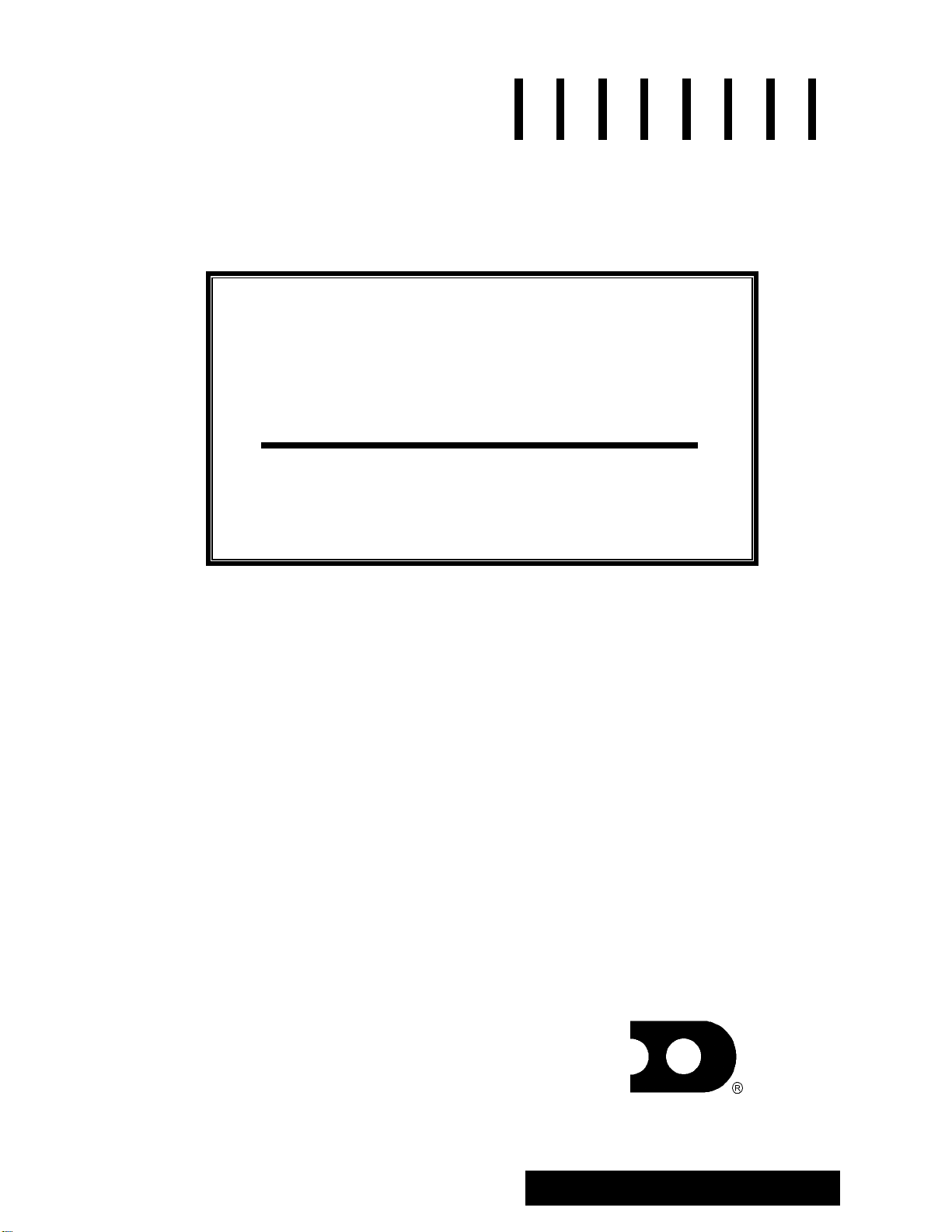
Figure 1 illustrates a Daktronics drawing label. The drawing number is located in the lower-right
corner of the drawing. This manual refers to drawings by listing the last set of digits and the letter
preceding them. In the following example, the drawing would be referred to as Drawing A-114667.
Introduction
1-1
Page 8
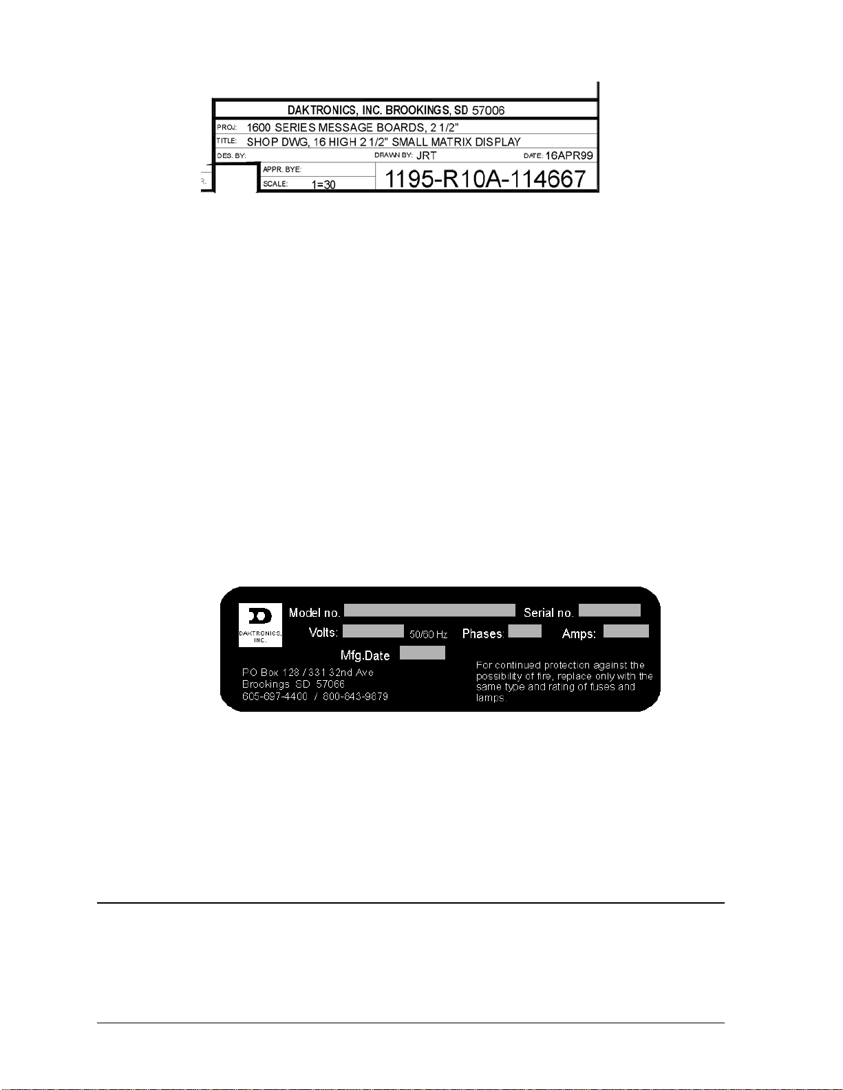
Figure 1: Drawing Label
All references to drawing numbers, appendices, figures or other manuals are presented in bold
typeface, as shown below.
“Refer to Drawing A-114667 for the location of the panel board.”
In addition, any drawings referenced within a particular sub-section are listed at the beginning of that
sub-section in the following manner:
Reference Drawing:
Shop Drawing; 16 High 2 ½” Small Matrix.......................................... Drawing A-114667
Referenced drawings are found in the Appendix A.
Daktronics identifies manuals by an ED number located on the cover page of each manual. Its ED
number will identify any manuals referenced in this manual. For example, this manual would be
referred to as ED-12161.
The serial number and model numbers can be found on the ID label, located on the display. This label
will look similar to the one shown in Figure 2. When calling Daktronics Customer Service, please
have this information available to ensure that your request is serviced as quickly as possible.
Figure 2: Display ID Label
Daktronics displays are built for long life and require little maintenance. However, from time to time,
certain display components will need replacing. The Replacement Parts List in Section 4 provides the
names and part numbers of components that may need to be ordered during the life of this display.
Following the Replacement Parts List in Section 4 is the Exchange/Replacement Procedure. Refer to
these instructions if any display component needs to be replaced or repaired.
1.2 Daktronics Nomenclature
To fully understand some Daktronics drawings, such as schematics, it is necessary to know how
various components are labeled in those drawings. You will find this information useful when trying
to communicate maintenance or troubleshooting efforts.
1-2
Introduction
Page 9
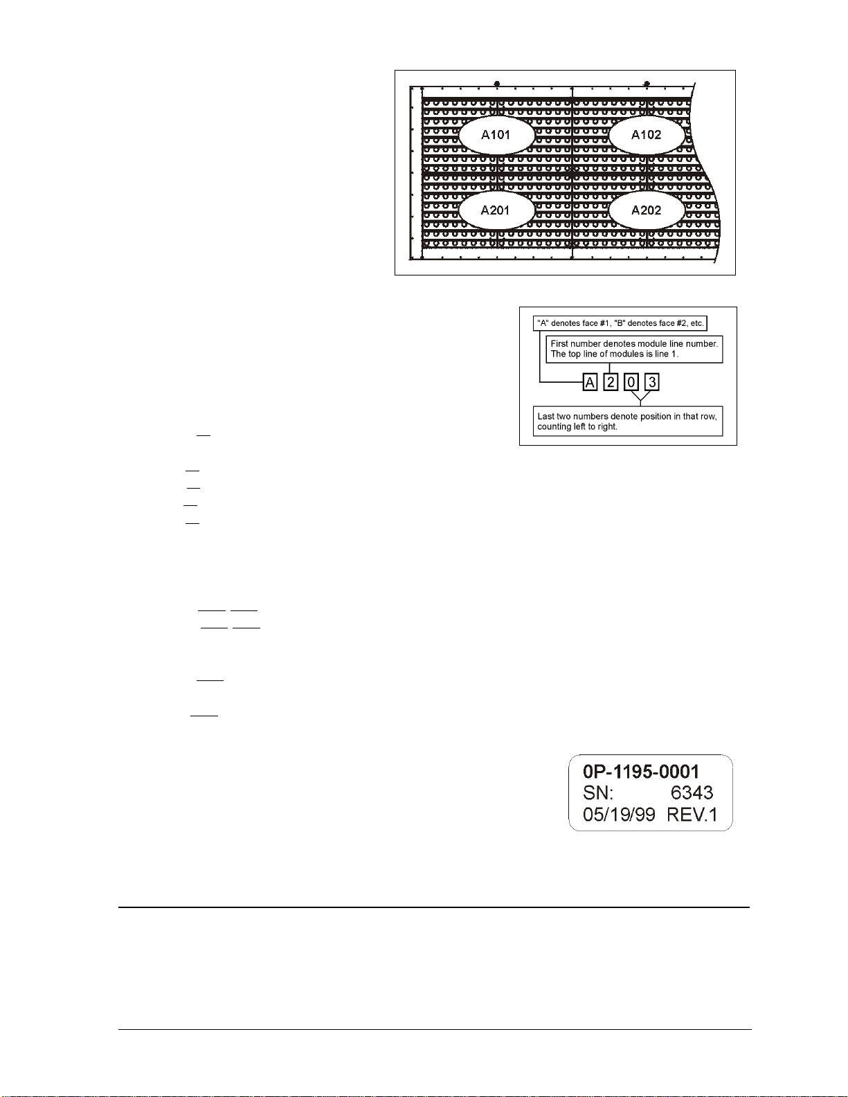
A module is the building block of the
Daktronics sign. By placing modules sideb
y-side and on top of one another a sign of
a
ny size can be designed and built.
Indiv al modules can be easily remov
idu ed
fr
om the sign if required. Figure 3
illustrates how Daktronics numbers
modules on a sign. Figure 4 breaks down
the module numbering method.
The label “A” on a drawing ty
d
enotes an assembly. An assembly can be
ngle circuit board or a collection of
a si
com
ponents that function together, usually mounted on a
sing
le plate or in a single enclosure. Assemblies are divided
into o
tw types: those that route signal and those that route
pically
Figure 3: Example M odule Numbering – 16x80 Display
power.
In addit t be found on
v
ion, the following labeling formats migh
arious Daktronics drawings:
· “TB??” denotes a termination block for power or
signal cable.
· “F??” denotes a fuse.
· “E??” denotes a grounding point.
“J??
· ” denotes a power or signal jack.
“P??
· ” denotes a power or signal plug for the opposite jack.
Figure 4: Module Numbering
Daktron
requesti ement parts from Daktronics Customer Service. Take note of the following part
number
ics part numbers are commonly found on drawings. Those part numbers can be used when
ng replac
formats. (Not all possible formats are listed here.)
“0P-????
·
· “0A-????-????” denotes an assembly, such as a circuit board and the plate or bracket to which
-????” denotes an individual circuit board.
it is mounted. A collection of circuit boards working as a single unit may also carry an
assembly label.
· “W-????” denotes a wire or cable. Cables may also carry the assembly numbering format in
certain circumstances. This is especially true of ribbon cables.
· “F-????” denotes a fuse.
“T-????” denotes a tr
· ansformer
· “PR-?????-?” denotes a specially ordered part.
Most ci
a label t
assembl
label to ates a typical label. The
part number is in bold.
rcuit boards and components within this SunSpot display carry
hat lists the part number of the unit. If a circuit board or
y is not listed in the replacement parts list in Section 4, use the
order a replacement. Figure 5 illustr
Figure 5: Typical Label
1.3 Definitions
Driver: A modular unit that receives display information from the controller and converts it to drive
signals that switches the lamps on and off. It controls an array of lamps that is either 7 pixels high by
16 pixels wide or 8 pixels high by 16 pixels, depending on display specifications.
Introduction
1-3
Page 10

Incandescent: Displays that use lamps with filaments that are heated to incandescence by an electric
current.
Lampbank: An 8x16 or 7x16 array of lamps, depending on display specifications.
Panel Board: The power junction box that connects incoming power to the display.
Matrix: The hei area according to the number of rows and columns of
ixels.
p
ght and width of a display
Mod
em: A device that allows data to be sent or received over a phone line.
ixel: The smalle ff. Each
P st single point of light on a message center that can be turned on or o
dividual lamp o
n a SunSpot display
is considered a pixel. in
RS232: A standard PC com
munication type with a maximum cable length of 25 feet (8 meters).
RS422: A standard differ
k
ilometers).
ential communication type with a maximum cable length of 4000 feet (1.2
SunSpot7
: Monochrome incandescent message cente
r displays.
Venus7
1500: A Daktronics designed, Windows based software used to create and edit messages o
n
the displays.
.4 Display Features & Overview
1
Reference Drawings:
System Riser Diagram, RS422 Incandescent Displays....................... Drawing A-148859
System Riser Diagram, RS232 Incandescent Displays ....................... Drawing A-148870
System Riser Diagram; Fiber Incandescent Displays.......................... Drawing A-148878
System Riser Diagram; Modem Incandescent Displays...................... Drawing A-148884
Shop Drawing, 7**-24 IOC-L ............................................................... Drawing B-149589
Shop Drawing, 16**-24 IOC-L............................................................. Drawing B-149590
Daktronics AB-1010 SunSpot
animation with a w available along with high visibility and affordable
quality. he combination of reflector lamps and horizontal louvers create a display that is excellent for
T
ide variety of special effects
®
incandescent displays offers eye-catching text messages, graphics, and
long distant viewing.
T
he AB-1010 Series displays are operated using a Venus
llows displays to run text messages, graphics and animations using a Windows based IBM-
a
compatible computer. The controller can operate up to 240 sig
operate displays via telephone modem. Refer to ED-12717 for more informati
®
1500 controller. The Venus 1500 softwar
ns within a local network and can also
on.
e
T
he displays are available in 24O, 30O, 36O, 48O and 60O character heights. In addition, they may be
single-stand alone displays or they may have a m
a
dditional display features:
aster-echo configuration. The following lists
· C
onstruction: All aluminum cabinet with welded extrusion frame. Louvered egg crate light
dividers attached directly to each lampbank section. D
isplays ordered with reflectorized lamps do
not have light dividers. Lift eyes provided. Center cabinets not included
· Finish: Flat black acrylic enamel paint.
1-4
Introduction
Page 11

· Lam
ps: 30-watt (30R20) or 50-wa
tt (50R20) 6000 hour reflector lamp
· Electrical: Standard 120/208 3-phase p
panels completely wired and assembled
conduit size depends upon cable
used.
· Service Access: Each lampbank section
access to lamps for replacement
; lamp dividers may be removed for easier lamp access.
Each incandescent display has its own uniq
following explains each model n
umber: AB-1010-HHxWW-XX
AB = Matrix
1010 =
, Incandescent Outdoor
Series Nu
HH = Matrix Heig
WW = Matrix Width (32, 48, 64
XX = Overall Character Height (
ower. Internally mounted load centers and signal junction
. Power cable requirements determined by local codes;
hinges upward for front access to lamp drivers. Front
ue model number that describes its characteristics. The
m
ber
ht (7, 16, 24 or 32)
, 80, 96)
24, 30, 36, 48, 60)
Introduction
1-5
Page 12

Page 13

Section 2: Mechanical Installation
Dak
tronics engineering staff must approve any changes that may affect the weather-tightness of the
sign ktronics
. If you make any modifications, you must submit detailed drawings of the changes to Da
r evaluation and approval, or you may void the warranty.
fo
Daktronics is not responsible for installations or the structural int
o
thers. The customer is responsible to ensure a qualified structural engineer approves the structure and
any additional hardware.
2.1 Mechanical Inst a
ecause every instal si s SunSpot
B
igns. This section contains general information only and may or may not be appropriate for your
s
articular installation.
p
A qualified individual must make all decisions regarding the mounting of this sign.
Read both the mechanical and electrical installation sections of this manual before beginning
any installation procedures.
lation te i unique, Daktronics has no single procedure for mounting
all tion Overview
egrity of support structures done by
2.2 Support Structure Design
Support structure design depends on the mounting methods, sign size and weight. The structure design
is critical; only a qualified individual should mount the sign. Sign height and wind loading are also
critical factors. It is the customer’s responsibility to ensure that the structure and mounting hardware
are adequate. Daktronics is not responsible for the installations or the structural integrity of support
structures done by others.
The installer is responsible to ensure the mounting structure and hardware are capable of
supporting the sign and agrees with local codes.
Before beginning the installation process, verify the following.
· The mounting structure provides a straight and square frame for the sign.
· The mounting structure supports the sign without yielding at any unsupported points after
mounting.
· Clearance: 3O of unobstructed space is available below the sign for filter removal from the sign. 1
¼O of unobstructed space is available above the top of the sign.
Correct any deficiencies before installation.
Mechanical Installation 2-1
Page 14

2.3 Ventilation Requirements
Reference Drawings:
Shop Drawing, 7**-24 IOC-L ............................................................... Drawing B-149589
Shop Drawing, 16**-24 IOC-L............................................................. Drawing B- 149590
Fans mounted in the bottom of the sign allow for ventilation. Maintain a minimum distance of 3O
(7.62cm) below the sign to maintain proper airflow. Refer to the appropriate shop drawing for
additional information.
If the sign cabinet is completely enclosed:
· Provide 6 square inches of unobstructed opening per module to ensure adequate cooling.
· Make allowances to compensate for the percentage of material covering the openings in the
structure.
· For adequate cooling, the cabinet may require forced ventilation. If the enclosed cabinet must use
forced ventilation, it must ventilate at a rate of 10 cubic feet per minute per module (10.6O x 10.6O
active area).
Failure to comply with these requirements voids the Series AB-1010 sign warranty.
2.4 Display Definitions
Reference Drawings:
Shop Drawing, 7**-24 IOC-L ............................................................... Drawing B-149589
Shop Drawing, 16**-24 IOC-L............................................................. Drawing B- 149590
Daktronics typically offers two
display configurations, single face
displays and 2V displays. Figure
6 illustrates each of these two
display types.
A 2V display consists of two
single face units, one master and
one echo. The two sided of this
display may be mounted at any
angle between 0 and 90 degrees.
An interconnect harness used to
power the echo unit is coiled up
inside the master unit. Refer to
Drawing B-139876 for your
sign’s specifications.
2.5 Lifting the Sign
The top of the sign is equipped with eyebolts that are used to lift the unit. Take special care to ensure
that the rated load of the eyebolts is not exceeded. Refer to the information at the end of this section
labeled Eyebolts to determine the allowable load of the eyebolts.
Figure 6: Display Configuration
2-2
Mechanical Installation
Page 15

Figure 7 illustrates both the correct (left example) and the incorrect (right e
a sign. Lift the sign as shown on the left, with the lifting bar. Do not connec
th
e central lifting point; doing so may cause the eyebolts to fail.
xample) method of lifting
t the eyebolts directly to
Use every lifting point provided!
Do not attempt to permanently support the
ign by the eyebolts.
s
If removing an eyebolt from the display,
plug the hole with a bolt a
s
ealing washer that was removed from the
nd the rubber
Figure 7: Lifting the Sign
eyebolt.
2.6 Display Mounting
Reference Drawings:
Shop Drawing, 7**-24 IOC-L................................................................Drawing B-149589
Shop Drawing, 16**-24 IOC-L..............................................................Draw i n
The method used to mount signs varies greatly from location to location; as such, this manual covers
only general mounting topics.
It is t installer’s responsibility to ensu
he re the installation adequately meets local codes and
standards. The installer is also responsib
le for the mounting method and the hardware.
Before beginning the installation process, verify the following items.
· The mounting structure will provide a straight and square frame for the sign. Height variation in
any four-foot horizontal section may not exceed ¼- inch.
· The mounting structure
will not give way at any unsupported points after the sign is mounted.
The back of the sign uses 3x3 mounting clips at the
locations shown in the Shop Drawings; one set is
ounted to the back of the display and another set is
m
mounted to the structure. The two sets of mounting
clips are joined using ½O Grade-5 bolts; refer to
g
Fi ure 8. These clips assist in mounting the sign.
Remember to have all mounted signs inspected by a
qualified structural engineer.
customer must have a qualified structural engineer
The
review the number of attachment points needed and
the wall structure to ensure both meet all nati
lo
cal codes. Daktronics recommends using all clip
an
gles as attachment points.
onal and
Figure 8: Mounting Example
1. Carefully uncrate the sign. Look each side of the sig n ov er for damage during shipping. I f y ou find
damage, call Daktronics Customer Service at the numbers listed in Section 4.14.
2. Weld or use ½O Grade-5 bolts and hardware to secure the mounting clips to the support structure
as shown in the Shop Drawing.
3. Following the guidelines described in Section 2.4, lift the sign into position on the support
structure.
g B-149590
Introduction
2-3
Page 16

4. Line up the holes on both sets of mounting
angles (those on the back of the sign and those on the
support structure) and attach with ½O Grade-5 bolts.
5. Refer to Section 3 for
6 Upon completing installation, carefully inspect the sign for any holes that may allow water to seep
.
information on routing power and signal.
into the sign. Seal any openings with silicone. If you remove the eyebolts on the top of the sign,
the holes with bolts and the rubber sealin
plug g washers that you removed with the eyebolts.
2.7 Mounting Optional Light Detectors & Temperature Sensors
If your display has an optional light detector or an optional temperature sensor, refer to Appendix B
r information on installation.
fo
2.8
Prop Rods
Pro
p rods are stored in the master display behind the left most lampbank for shipment. The prop rods
secu
re the socket panels open for front access to display electronics. Secure the end of the prop rod
with the cotter pin into the pre-drilled holes in the bottom angle of the display. Secure the rod “T”
shaped end to the bracket on the rear of the socket panel.
rop rods are for safety use. Any deviation from their recommended use may cause serious bodily
P
injury or damage to the display.
2-4
Mechanical Installation
Page 17

Section 3: Electrical Installation
3.1 Common Connectors
This display uses many different types of co
care when disengagin
g any connector so as not to dam ag e the connector, the cable or the circuit board.
When pulling a connector plug from a j
itself. Pulling on the wires may damag
The follo
m
aintenance. Not all of these connectors are found in every display.
wing information presents some common connectors that may be encountered during display
1. Phone Jacks (RJ11 Connector
s):
RJ11 connectors, as seen in Figure 9, are similar to the
telephone connectors f
ound in homes and are used on the
ends of cable. In order to remove this plug from the jack,
depress the small clip on the underside of the plug.
Before replacing an RJ11 connector, spray it with Deoxit
contact cleaner to remove a
signal problems. In addition, apply a generous amount of
Cailube
™
protector paste to the plug before inserting it into
ny foreign matter that may cause
the jack. This paste will protect both the plug and the jack
from corrosion. Both the Deoxit and the Cailube can be
found in the tool kit accessories package included with this
display. Refer to the replacement parts list in Section 4 if you need additional
quantities of either.
2. Mate-n-Lok
The n-Lok connectors found in this display are white and come in a
Mate-
J Connectors:
variety of sizes. Circuit boards often used 9-pin M
while four-pin connectors and two-pin connecto
power connection. Figure 10 shows a four-pin M
To remove the plug form the jack, squeeze the p
the side of the plug and pull it from the jack.
3. Phoenix
Phoenix-style connectors a
J-Style Connectors:
re usually green and
are often used for signal termination on circuit
boards. Refer to Figure 11. Strip one-quarter
inch of insulation from the wire prior to
termination. To remove a wire, turn the above
screw counter-clockwise to loose the connectors
grip on the wire. To inser
t a wire, push the bare
wire into the connector and turn the above screw
clockwise to lock the wire into place.
5. Termination Blocks:
Termination blocks usually conne
coming into the display from an external source. Most signal wires will come with forked
connectors
crimped to the ends of the wire. Power wires need to have one-half inch of insulation
nnectors for power and signal termination. Take special
ack, do not pull on the wire or cable; pull on the jack
e the connector.
™
Figure 9: RJ11
Connector
ate-n-Lok connectors
rs are often used for
ate-n-Lok connector.
lastics locking clasps of
Figure 11: PhoenixStyle Connector
Figure 12: Termination Blocks (left: signal; right: power)
ct internal power and signal wires to wires of the same type
Figure 10:
Mate-n-Lok
Connector
Electrical Installation 3-1
Page 18

stripped from the end of the wire prior to termination. Tighten all screws firmly to ensure a good
electrical connection. Refer to Figure 12.
3.2 Before Installation
eference Drawings:
R
System Riser Diagram, RS422 Incandescent Displays ....................... Drawing A-148859
ys ing A-148870
S tem Riser Diagram, RS232 Incandescent Displays....................... Draw
System Riser Diagram; Fiber Incandescent Displays.......................... Drawing A-148878
System Riser Diagram; Modem Incandescent Displays...................... Drawing A-148884
Shop Drawing, 7**-24 IOC
Shop Drawing, 16**-24 IOC-L............................................................. Drawing B- 149590
Before installing signal
w
ill need to be made, including the panel board, the V15DR, the Junction Box (J-B ox) and the driv ers.
Refer to Figure 13 for a typical layout of the electrical components within a 16x64 matrix display.
Electrical component locations may vary with display size. Refer to DrawingsB-149590 and B-
149589 for component layout.
and power to the display, locate the necessary display parts where connections
-L ............................................................... Drawing B-149589
Figure 13: Component Locations
3.3 Power
Proper power installation is imperative for proper display operation. The following sub-sections give
details of display power installation.
Grounding
Displays MUST be grounded according to the provisions outlined in Article 250 of the
National Electrical Code
The display system must be connected to earth-ground. Proper grounding is necessary for reliable
equipment operation. It also protects the equipment from damaging electrical disturbances and
lightning. The display must be properly grounded or the warranty will be void.
The material of an earth-ground electrode differs from region to region and from conditions
present at the site. Consult the National Electrical Code and any local electrical codes that may
apply. The support structure of the display cannot be used as an earth-ground electrode. The
support is generally embedded in concrete, and if in earth, the steel is either primed or it corrodes,
making it a poor ground.
3-2
®
. Daktronics recommends a resistance to ground of 10 ohms or less.
Electrical Installation
Page 19

Branch Circuit Grounding
A grounding electrode at separate structures/displays shall not b
e required where only one
branch circuit supplies the structure and the branch circuit includes an equipment grounding
conductor for grounding the non-current-carrying parts of all equipment.
Power Installation
There are two considerations for power installation; installation with ground and neutral
conductors provided and installation with only a neutral conductor provided. These two power
installations differ slightly, as described in the following paragraphs:
Installation with Ground and Neutral Conductors Provided
For this type of installation, the power cable must contain an isolated earth-ground conductor.
Under this circumstance, do not connect neutral to ground at
the disconnect or at the display.
This violates electrical codes and voids the warranty. Use a disconnect so that all hot lines and
neutral can be disconnected. Re
Code requires the use of a lockable power disconnec
fer to Figure 14 for installation details; the National Electrical
t within sight of or at the display.
Figure 14: Installation with Ground and Neutral Conductor Provid ed
Installation w ith Only a Neutral Conductor Provided
Installations where no grounding conductor is provided must comply
the National Electrical Code. If the installation in question meets all o
article 250-32, the following guidelines m
Figure 15: Installation with only Neutral Conductor Provided
ust be observed:
with article 250-32 of
f the requirements of
Electrical Installation
3-3
Page 20

· Connect the grounding electrode cable at the local disconnect, never at the display
panelboard.
·
A disconnect that opens all of the ungrounded phase conductors should be used.
· The neutral and the grou
Refer to Error! Reference source not found. for installation details.
nd conductors should be bonded in the display panelboard.
.4
3 Electrical Service Requirements
R ference Drawings: e
Two Wire/Three Wire/ Two Surge Arresters (A-1129) ........................... Drawi ng A-74902
System Riser Diagram, RS422 Incandescent Displays....................... Drawing A-148859
System Riser Diagram, RS232 Incandescent Displays ....................... Drawing A-148870
System Riser Diagram; Fiber Incandescent Displays.......................... Drawing A-148878
System Riser Diagram; Modem Incandescent Displays...................... Drawing A-148884
Power Specs, Sunspot........................................................................ Drawi ng A-148967
The panel board is provided internally for display power distribution to the driver circuits. Refer
tables below for electrical service requirem
these tables are calculated based on the maximum wattage lamp offered for each display size. The
installer is to supply an external mounted fused main disconnect(s) and wire to the panel board. The
installer must field punch a hole or holes in the cabinet at the appropriate location for power cable
entrance to panel board.
The panel board is provided in the master display cabinet. Single panel boards are always located to
the left of the right-most lamp driver enclosure assembly. When a second panel board is provided, it
will be found to the left of the first panel board (between two lamp driver enclosure assemblies).
When a second panel board is provided, two externally mounted fused main disconnects are required.
Refer to the tables below for the number of disconnects required for your particular application.
Surge Suppressors are installed in
Note: the panel board(s) but are not hooked up. They must be
co
nnected when the main power is hooked up to the panel board. Refer to Drawing A-74902 for the
pr
oper connections.
ents. Note: All electrical service requirements listed in
3.5 Panel Board Assignments
Reference Drawings:
Lamp Driver, 16 Column w/ Fan............................................................ Drawing A-37070
Drawin : Two
or f
illustrated in the following set of tables) where A indicates the driver/module number.
Thi s.
Not
g A-37070 illustrates the electrical distribution from the panel board to the drivers. Note
our breakers feed each driver. All power wires are labeled with a number in the format A (as
s table is for a 16x64 single face display. It has a 125-amp panel board and uses 16 of 20 position
e that two breakers feed each driver.
Breaker Wire Driver Wire Breaker
1 A101 (Black) A101 A101 (Red) 2
3 A102 (Black) A102 A102 (Red) 4
5 A103 (Black) A103 A103 (Red) 6
7 A104 (Black) A104 A104 (Red) 8
9 A201 (Black) A201 A201 (Red) 10
to the
3-4
Electrical Installation
Page 21

ck) A202 A202 (Red) 12 11 A202 (Bla
13 A203 (Black) A203 A203 (Red) 14
15 A204 (Black) A204 V15DR/Fans 16
17 A204 (Red)
19 Not Used
A list similar to one of the above is located inside the panel board door.
·
The square D 20 amp QO breaker is UL listed for 1 or 2 #12 AWG wire(s).
·
Breakers above the dark solid line within the tables are for line one (up
· per 8 rows of lamps) of the
display. Breakers below the solid line are for line two (lower 8 rows of lamps) of the display.
3.6
Refere
The method used to route and terminate signal at the display differs according to the type of control
cable used. The following sets of instructions cover the various control options listed in Section 1.4 or
3.7. Refer to the procedure that is appropriate for your display. Drawing A-103727 illustrates Venus
1500 signal terminations for RS232, RS422, modem and fiber optic control cables.
Signal Termination From Computer To Display
nce Drawing:
00 Signal Termi nation...................................................................Drawing A-103727
V15
Not Used 18
Not Used 20
3.7 Signal Junction Box Terminations
Reference Drawing:
System Riser Diagram, RS422 Incandescent Displays........................Drawing A-148859
System Riser Diagram, RS232 Incandescent Displays........................Drawing A-148870
System Riser Diagram; Fiber Incandescent Displays ..........................Drawing A-148878
System Riser Diagram; Modem Incandescent Displays.......................Drawing A-148884
Drawing A-4 box. The
signal wires f in the first line of the display are connected to TB31. e signal wires
for the second line are connected to TB32. Each signal pair location is labeled with the driver
number n correspondence to their
connect
the + an
2461 shows examples of a one- and a two-line display signal junction
or the drivers Th
it corresponds to. Connect the signal wire to the junction box i
ion orientation at the controller (refer to appropriate controller manual). Be sure to note
d - signal orientation.
RS232
One end of the signal cable should be terminated to the 6 position terminal block in the display
labeled “IN RS232” (TB1). The opposite end is terminated at the J-Box at the display structure.
The laptop PC connects to the J-box through the serial cable. Refer to Drawing A-148870 for the
correct wire type.
J-Box Field Cabling Terminal Block (Data In)
Pin 1 (N.C.)
Pin 2 (N.C.)
Pin 2 (RX-P) Clear Pin 3 (TX-P)
Pin 3 (GND) Shield Pin 4 (GND)
Pin 1 (TX-P) Black Pin 5 (RX-P)
Pin 6 (N.C.)
Electrical Installation
3-5
Page 22

RS422
Route conduit and cable from the PC running Venus 1500 to the left end of the master display.
tin e cable into the controller box fitting labeled “Signal In.” One end of the signal ca
Con u ble
should b 2).
Drawing A-103727 is an example of the termination block. The other end is terminated at the
sign oom (as seen in the
following table). Refer to Drawing A-148859 for the correct wire type.
e terminated to the 6-position terminal block in the display labeled “RS422 IN” (TB
al converter (Daktronics part number 0A-1127-0237) in the control r
Signal Converter (J4/J5) Field C
Pin 1 (GND) Red Pin 1 (GND)
Pin 2 (RX-P) Black Pin 2 (TX-P)
Pin 3 (RX-N) Brown Pin 3 (TX-N)
Pin 4 (TX-P) White Pin 4 (RX-P)
Pin 5 (TX-N) Blue Pin 5 (RX-N)
Pin 6 (GND)
Shield (Bare) N.C.
abling Terminal Block (Data In)
Green Pin 6 (GND)
Modem
Terminate the signal telephone wires to J-1094 as designated on Drawing A-130246. Refer to
Drawing A-148884for the correct wire type.
Telephone Wires Terminal Block
N.C. Pin 1
N.C. Pin 2
TIP-P Pin 3
Ring-P Pin 4
N.C. Pin 5
N.C. Pin 6
Note: Ask the phone line installer which wire color is “tip” and which is “ring”.
Fiber Optic
Route conduit and fiber cable from the PC to the left end of the master display. Continue routing
fi r to the controller box. Connect fibe
be r cable from the signal converter of the PC to the fiber
card in the display as described on the f
wire type.
Signal Converter Sign A
Data Out (J2 & J3) Data In (J4 & J5)
J2 (TX1) J5 (RX2)
J3 (RX1) J4 (TX2)
ollowing table. Refer to Drawing A-148878for the correct
Field Cabling
3-6
Electrical Installation
Page 23

3.8 Master/Echo Connection
Reference Drawi
Schematic, Sunspot 24 .......... ............ .......... awing B-141704
System Riser ram, R ndesce t Displa .......... awing A-148859
System Riser Diagram, RS232 Incandescent Displays........................Drawing A-148870
.....Drawing A-148878
System Riser Diagram; Fiber Incandescent Displays .....................
Drawing A-148884
System Riser Diagram; Modem Incandescent Displays.......................
For .6.
a master/echo display system, signal is hooked up to the master display according to Section 3
ignal is then sent from the master display’s signal junction box to the echo’s corresponding signal
S
junction box with 22-
ng:
”, 30” and 36” ... .................... ...Dr
Diag S422 Inca n ys............ ..Dr
gauge, shielded wire.
3.9 Light Detecto
R
efer to Appendix B for information on installing the light sensor.
If your display has an optional temperature sensor, refer to Appendix B for information on electrical
installation.
rs & Optional Temperature Sensors Electrical Connection
Electrical Installation
3-7
Page 24

Page 25

Section 4: Maintenan
IMPORTANT NOTES:
1. Disconnect power before any repair or maintenance work is done on the
display!
2. Any access to internal display electronics must be made by qualified
service personnel.
3. Disconnect power when the display is not in use.
ce & Troubleshooting
4.1 Maintenance & Troubleshooting Overview
The Series AB-1010 incandescent displays are front accessible; meaning access to the internal
omponents can be gained only from the front of the display.
c
This section p
· Signal & Power Overview: gives a quick description of how power and signal route through
· Component Access & Replacement: explains how to open the display and how to access and
· Maintenance: lists a number of steps to take to keep this display in safe, working order.
· Troubleshooting: lists some possible display malfunctions and provides a number of
· possible causes for that malfunction.
· Replacement Parts Lists: lists the part description and part number of display components
· that could possibly need replacing during the life of this display.
· Daktronics Exchange/Repair & Return Programs: explains the Daktronics component
rovides the following display information.
the display system.
replace components within.
return policy.
4.2 Signal Overview
Reference Drawing:
System Riser Diagram, RS422 Incandescent Displays........................Drawing A-148859
System Riser Diagram, RS232 Incandescent Displays........................Drawing A-148870
System Riser Diagram; Fiber Incandescent Displays ..........................Drawing A-148878
System Riser Diagram; Modem Incandescent Displays.......................Drawing A-148884
Signal travels from the Venus 1500 controller to the Venus 1500 Display Receiver (V15DR) located
inside the sign. Refer to Drawings A-148859, A-148870, A-148878 and A-148884. The signal
junction boxes for each row of modules receives the data sent by the V15DR and distributes it to the
appropriate drivers. The drivers in turn distribute the signal to the display modules.
4.3 Power Overview
Power routes from the power disconnect to the panel board within the display. From there, power
routes to the display drivers; the drivers distribute the power to individual components within the
display. Refer to the Schematic.
Maintenance & Troubleshooting
4-1
Page 26

4.4 Component Access
The Series AB-1010 SunSpot displays have front component access. The following sections cover
how to open the three different types of displays.
Top Revolving Socket Panels
1. Turn the two bottom fasteners securing the socket panel ¼-turn counter-clockwise and swing
the panel up. The fasteners remain in the socket panel.
2. Brace the socket panel(s) with the prop rod(s).
Middle Revolving Socket Panels
Turn the two top fasteners securing the socket panel ¼-turn counter-clockwise and swing the
panel down. The fasteners remain in the socket panel and the panel rests on a landing plate.
Side Revolving Socket Panels
1. Turn the two side fasteners securing the socket panel ¼-turn counter-clockwise and swing the
panel to the side. The fasteners remain in the socket panel.
2. Secure the pins into place by the pivot(s).
4.5 Lamp Testing & Replacement
Venus 1500 Lamp Test
To run a lamp test on a Venus 1500 system the display must be started in test mode. To start the
display in test mode complete the following steps:
1. Turn off display power at the power disconnect.
2. Access the Venus 1500 display controller.
3. Write down the current settings of the DIP switch on the underside of the MDC board located
inside the Venus 1500 Display Receiver (V15DR). Refer to Section 4.9.
4. Set the DIP switches on the MDC board on the display controller to address zero (flip all the
switches toward the numbers on the circuit board).
5. Restore power and observe the lamp test.
To exit test mode complete the following steps:
1. Turn off display power.
2. Set address back to original setting.
3. Restore power to display.
Note: The Venus 1500 software, version 2.0 or higher, has a “Test Pixel” option. Refer to ED-
12717.
Lamp Replacement
1. Locate the defective lamp using the testing procedure above.
2. Turn off power to the sign before replacing lamps to avoid damaging the driver.
3. Replace defective lamps only with Daktronics approved lamps of the same wattage; refer to
Section 4.13. Note: Do not over-tighten lamps!
Note: Light dividers may be removed for easier lamp access. Remove the screws at the top and
bottom of the light divider and lift off.
4-2
Maintenance &
Troubleshooting
Page 27

4.6 Socket Replacement
Reference Drawing:
Lampbank Assembly and Wiring, 8x16-36 IOC-L................................Drawing C- 147146
1. Open th s
2. Remove the power and signal wire to the bad socket. Refer to Detail B and Detail C on Drawing
C-14714
3. Remove the
4. Remove
5. Snap the new socket into place.
6. Replace the lamp, rewire the socket (refer to Detail D on Drawing C-147146) and secure the
socket panel.
.7 Lamp Driver
4
eference Drawing: R
Lamp Driver, 16 Col., w/Fan..................................................................Draw i ng A-37070
Shop Drawing, 7**-24 IOC-L................................
Shop Drawing, 16**-24 IOC-L..............................................................Draw i ng B- 149590
The lam lamps of the incandescent displays on and off. This unit receives display
informa
Ref to
er Section 4.12, Troubleshooting, if the display malfunctions. If a lamp driver needs to be
repl ed
ac , follow the steps below.
1.
Shut power off to the display.
2. B-149590.
Locate the driver you need to replace using Drawings B-149589 and
3. e
Op n the display according to Section 4.6.
4. Rem fastening the cover on the driver enclosure and lift off the cover.
Unplug wiring connections (J1 through J20).
5.
Remove the two wing nuts in the top corners of the enclosure and remove the driver.
6.
7. Reverse Steps 1 through 4 to i
.8
4 Fuse Replacement
A 7 or 8 high column of pixels has one fuse. If an entire column is out, a fuse may be blown.
To replace a blown fuse:
1. Shut power off to the display.
2. Gain access to the driver as stated in Section 4.7, Steps 1-3.
3. Remove the two driver cover wing nuts and lift off the cover to gain access to th
4.
Replace the blown fuses.
e di play according to Section 4.6.
6.
lamp in the bad socket.
the old socket.
................................Drawing B-149589
p driver switches the
tion from the controller and converts it to the drive signals that switch the lamps.
ove the screws
nstall the new driver.
e fuses.
Maintenance &
Troubleshooting
4-3
Page 28

eiver 4.9 Venus 1500 Display Rec
Reference Drawings:
2-Board V1500 Display Receiv er Wiring Layout.................................. Draw ing A-138543
Assy; V1500 Display Recvr, RS232/422..............................................Drawing B-130244
Assy; V1500 Display Recvr, Modem ................................................... Drawing B- 130246
r Optic..............................................Drawing B-130247
Sho .......................Drawing B-149589
Shop Drawing, 16**-24 IOC-L..........................
The signal from the Venus 1500 controller which routes signal
to e etc.,
in it r the
lo
The nts, including a controller board, a fan and two Current Loop
Out
To rem
1. Locate the V15DR placement within the dis
2. O n the display according to Section 4.4.
3.
4.
sy; V1500 Display Recvr, Fibe
As
Schematic, V15DR, 1500....................................................................Drawing B-140468
p Drawing, 7**-24 IOC-L ........................................
...................................Drawing B-149590
Venus 1500 Display Receiver receives
ach display driver (8 pixels/16 pixels). The Venus 1500 controller stores messages, schedules,
s memory. The controller is also addressable. Refer to Drawings B-149589 and B-149590 fo
cation of the V15DR.
V15DR consists of several compone
put cards.
ove a V15DR component from the display:
play on Drawings B-149589 and B-149590.
pe
Remove the screw on the bottom middle of the V15DR cover and lift off the cover from the
enclosure.
Individual parts in the V15DR may be removed from the enclosure by disconnecting the power
and signal connectors and removing the screws and lifting the components from the standoffs.
Controller Board and MDC Board
The table below lists the functions of the conne
Connector Function
J1 RS232 I n – CO M1
TB1 RS232 In – COM1
TB2 RS422 In – COM1
TB3 RS422 Out – COM1
TB4 RS232 In – COM2
TB5 RS422 In – COM2
TB6 RS422 Out – COM 2
J2 10 VAC I nput
J3 N/A
TB11, TB12 Current Loop Out
J11, J12, J13 Output to Current Loop Output cards
On the controller board are a number of diagnostic LEDs. The LEDs and their respec
functions and operations are listed in the following table.
ctors found on the controller board.
tive
4-4
Maintenance &
Troubleshooting
Page 29

LED
Function
Operation
Name
PWR Controller has power Always On
RUN Controller is running Flashes approximately once per second
LGHT Light Detector Input Light Level=Flash Rate
TEMP T emp Sensor Input Tem per at ur e=Flash Rate
RX2 Data In – COM1 On while Communicating
RX2 Data In – COM2 On while Communicating
The W1 and W2 jumpers
on the controller board
must be ON for modem
communication and OFF
r
fo all others: RS232,
RS422 and fiber optic.
Before this display can be
run in a sign network it
must have an address. The
display address can be set
using the DIP switches on
the MDC board. The
switches are on the
underside of the MDC
Figure 16: Controller Board
board near TB7 of the controller board. The following table lists the switch setting for various
addresses.
Address Switch Switch Switch Switch Switch Switch Sw
itch 2 Switch
8 7 6 5 4 3
1 OFF OFF OFF OFF OFF OFF OFF ON
2 OFF OFF OFF OFF OFF OFF ON OFF
3 OFF OFF OFF OFF OFF OFF ON ON
4 OFF OFF OFF OFF OFF ON OFF OFF
5 OFF OFF OFF ON OFF ON OFF OFF
6 OFF OFF OFF OFF OFF ON ON OFF
7 OFF OFF OFF OFF OFF ON ON ON
8 OFF OFF OFF OFF ON OFF OFF OFF
9 OFF OFF OFF OFF ON OFF OFF ON
10 OFF OFF OFF OFF ON OFF ON OFF
11 OFF OFF OFF OFF ON OFF ON ON
... ... ... ... ... ... ... ... ...
127 OFF ON ON ON ON ON ON ON
If ever the need arises to replace the Venus 1500 display controller, make sure the DIP switches
on the MDC are set for the same address as the old controller.
The controller board is one functional unit and must be replaced as a single device.
1
Maintenance &
Troubleshooting
4-5
Page 30

Complete the following steps to remove th
1. Flip the main disc
2. Disconnect all power and signal connections from the controller board.
3. Remove the nuts holding the controller board in the enclosure.
4. Write down the MDC switch settings.
5. If sending the controller back to Daktronics, keep the modem or fiber board (if present) and
all mounting hardware.
When installing a new display controller, verify the MDC DIP switch is set correctly.
onnect to the OFF position.
e Venus 1500 controller.
Current Loop Output Card Termination
The drawings provide guidelines for wiring the current loop output terminals and the driver for
each module of the display. The label on the inside of the V15DR enclosure shows where to plug
in each connector on
should be left unconnected.
Note: Dep
or configurations and wiring instructions may vary. Consul
manual for information specific to your site.
to Drawing A-138543 to see how each indi
module driver.
When all applicable terminations have been made on each terminal block, plug the terminal bloc
into the cards as designated on the label inside the enclosure.
The output cables should route downwar
knockouts at the bottom of the V15DR enclosure. The actual routing and the numbe
knockouts used varies with the display matrix size, V15DR model number and number of
conductors in each output cable.
When the cables connected, rou d and fasten the strain relief cable ties.
Be sure there is no excessive strain al wires.
ending on specific site requirements, displays may be shipped in different sections
each of the current loop output cards. Any unused current loop outputs
t the appendix at the end of this
t represents the height and length of your sectiAfter determining which V15DR model bes
vidual current loop output board connects to each
d between the output cards, and exit through the conduit
r of conduit
are te the cables downwar
on any of the individu
on, refer
ks
4.10 Display C stem
Reference Drawin
Fan Mounting D ..............................................................................Drawing A-43185
The display cooling m consists of a fan control thermostat assembly and cooling fans. The
thermostat assembly cated at the top the center of the master display cabinet. It stud mounts to
the display back shee aker panel board provides power to the fans
and thermostat.
thermostat assembly consists of a fuse (MDL-2 ½ amp, 125 volt), temperature sensor, mo
The mentary
tch and an enclosure. The temperature sensor activates the
swi display cooling fans to turn on at 140
rees Fahrenheit and to turn off at 110 deg
deg rees Fahrenheit. The momentary switch is used to check
fan operation. Check fans periodically to ensure they are running smoothly.
The stainless steel ball bearing fans provide cooling to the interior of the master cabinet only and are
thermostatically controlled. The fan air inlets are located in the bottom of the cabinet. The fans
4-6
ooling Sy
gs:
etail
syste
is lo and
t. The first bre to driver A101 at the
Maintenance &
Troubleshooting
Page 31

pressuri abinet a air from inside the cabinet out four small holes near each lamp.
ze the c nd force warm
Airflow cannot be restricted to the bottom of the display cabinet. If the display frame is “skinned”
over, adequate ventilati d thr in. Holes in the skin must be equal
to the si uantity the D e
ze and q of the holes provided in
bottom of the display ca
on ports must be provide oughout the sk
aktronics cabinet. Holes must be located in th
binet.
A faulty tat or c aired or replaced as soon as possible to extend the life
of the di electric cooling fa display should fail,
use the following guide orrect the
thermos ooling fan must be rep
splay’s al components. If a n or fans in the bottom of the
lines to locate and c malfunction.
1. ake sure the breakers to driver A101 (refer to the following table for A101 location) are in the
M
ON position and are not bl
2. securing the appropriate socket panel(s), and swing panel(s) up. Secure
Remove the two screws
panel(s) with prop rod(s)
3. h on the thermostat assembly to see if fans are activated. If one or more
Push the momentary switc
fans operate while othe
4. fails to activate any of the fans, remove the cover from the thermostat
If the momentary switch
ssembly and check for a blown fuse. Replace fuse if necessary (MDL-2 ½ amp, 125 volt).
a
5. tivates all the fans, test the thermostat by using a soldering iron to heat
If the momentary switch ac
up the thermostat (heat t
activate by heating up the th
own.
.
rs do not, replace the fans that do not work.
he metal behind the ½" hole punched in the cover). If the fans do not
ermostat, the thermostat assembly should be replaced.
If p ling system persist, contact a Daktronics customer service
roblems with the display coo
repr
esentative.
To splay, follow the steps below while referring to Drawing A-43185.
remove a fan from the di
1. splay according to Section 4.4.
Open the di
. Disconnect the power wiring to the fan.
2
3. h tt e d
Remove t e screws a
4. Lift the fan fro n
5. Re se the roce ins ew f
4.11 tructu spe
ver above p dure to tall a n an.
S ral In ction
m the sig
aching th. fan to the isplay.
Visual nspect nnua chec and le co , esp y at footings, structural
ly i signs a
tie points and gro ds. C faste d tig r rep requ
4.12 roubl tin
T eshoo g
und ro
lly to
heck
k paint
ners an
possib
hten o
rrosion
lace as
eciall
ired.
This section contains some ms t y be tered the A 0 S isplay
Possible remedies are provi is list does not eve sible m, bu s rep
some of the more on s ns th occ
comm ituatio at may ur.
sympto hat ma encoun with B-101 eries d .
ded. Th include ry pos proble t doe resent
em Pos olu
Probl sible S tions
Singl s do not light Inspec ps, so and w
e lamp
ps stay lit on both faces
mns do not light correctly
Colu n.
· t lam ckets ires.
· Switch the nine-pin Mate-n-Lok plugs controlling that
column on the driver. If the problem moves, the driver is
defective and needs to be replaced.
· Switch the plugs on theLam driver. If the problem moves, the
driver is defective and needs to be replaced.
· Check the common (black) wire to the colum
· Check the breaker in the panel board.
Maintenance &
Troubleshooting
4-7
Page 32

· Check the fuse for that colum
· Check the power connection to the driver.
· Check the
power terminal in the display.
Col r board. umns turn on out of sequence · Check the plugs at the drive
Dis
ma
nually housing.
· Check the light sensor for obstruction.
eck the wiring to the circuit card in the light sensor play intensity cannot be controlled · Ch
main breaker, disconnect, power source and
n in the driver.
4.13 Replacement Parts List
Part Number Parts Description
Driver, 16 col., w/Fan 0A-1033-0125
Fuse; AGC-1/2, 1/2A 250V F-1000
Fuse; AGC-10, 10A, 32V, Glass F-1006
Fuse; Thermostat Assembly, MDL-2 1/2A, 125V F-1002
Lamp; 33 Watt, 33A19 (clear) DS-1075
Lamp; 30 Watt, 30A15 (clear) DS-1076
Lamp; 30 Watt, 30R20, 2000 Hrs. DS-1094
Lamp; 30 Watt, 30R20, 6000 Hrs. DS-1126
Lamp: 15 Watt, 15S14 (clear) DS-1248
Socket; Med Base Lamp X-1046
Power Cord; 24” w/ 90 Angle Plug W-1069
Fan, 250 CFM, 115 VAC B-1019
Fan, 250 CFM, 230 VAC B-1020
Fan Finger Guard HS-1289
Controller II 0A-1146-0037
Current Loop Output Card 0P-1099-0002
Fan; 32 CFM, 115 VAC B-1010
Fan Finger Guard HS-1182
Fuse; AGC-2 ½ , 2 ½ A, 250V F-1001
Venus 1500 Manual, Version 2.0 ED-12717
SunSpot Series AB-1010 Manual ED-12161
4.14 Daktronics Exchange/Repair & Return Programs
To serve customers’ repair and maintenance needs, Daktronics offers both an exchange and a repair
and return program. The e
key components. This service is provided to qualified customers who follow the program guidelines
lained below. It is our pleasure to provide this service to ensure you get the most from your e
xp
Daktronics products. Please call our Help Desk (1-877 / 605-1113) if you have any questions
regarding the exchange program or any other Daktronics service.
When you call the Daktronics Help Desk, a trained service technician will work with you to solve the
quipment proble
em. You will work together to diagnose the problem and determine which exchange
replacement part to ship. If, after you make the exchange, the equipment still causes problems, please
contact our Help Desk immediately.
If the replacement part fixes the problem, package the defective part in the same packaging the
eplacement part arrived in, fill out and attach the enclosed UPS shipping dor
THE PART TO DAKTRONICS. (You may use the same box and packing the exchange part was
sent in.) This will speed up the transaction and alleviate confusion when the failed component arrives
xchange program reduces down time by providing timely replacement of
cument and RETURN
4-8
Maintenance &
Troubleshooting
Page 33

at Daktronics. (Daktronics expects immediate return of the exchange part if it does not solve the
problem.) For most equipment, you will be invoiced for the replacement part at the time it is shippe
d.
This invoice is due when you receive it.
Daktronics reserves the right to
auses other than normal wear and tear.
c
refuse equipment that has been damaged due to acts of nature or
If the defective equipment is not shipped to Daktronics within 30 working days from the invoice date,
it is assumed you are purchasing the replacement part and you will
voice represents the difference between the exchange price and the purchase price of the equipment.
in
be invoiced for it. This second
This amount is due when you receive the second invoice. If you return the exchange equipment after
30 w ou will be credited for the amount on the second invoice minus a
orking days from invoice date, y
restocking fee.
@To avoid a restocking charge, please return the defective equipment within 30 days from the
ice date.
invo
tronics also offers a Repair and Return program for items not subject to exchange.
Dak
ere to Send: To return parts for service, contact your local representative prior to shipment to
Wh
uire a Return Material Authorization Number (RMA#). If y ou hav e no local represen
acq tative, call the
D
aktronics Help Desk for the RMA#. This will expedite the receiving process.
Packaging for
E
lectronic components such as printed circuit boards should either be installed in an enclosure or
Return: Package and pad the item well so that it will not be damaged in shipment.
should be put in an anti-static bag before boxing. Please enclose your name, address, phone number
a
nd a clear description of symptoms.
Mail: Daktronics, Inc., Customer S
ervice
PO Box 5128
331 32nd Aven
ue
Brookings, SD 57006
Phone: Daktronics Help Desk: 1-877 / 605-1113 (toll free)
or 1-605 / 697-4034
Customer Service Fax: 1-605 / 697-4444
e-mail: helpdesk@daktronics.com
Maintenance &
Troubleshooting
4-9
Page 34

Page 35

Appendix A: Reference Drawings
Lamp Driver, 16 Col., w/ Fan.......................................................................Drawing A-37
Assy, Signal, 7 High Display..............
T
wo Wire/Three Wire /Tw o Sur ge Arres tor s.................................................Drawing A-74902
V1500 Signal Terminations.......................................................................Drawing A-103727
2 Board Retro Fit Wiring Layout................................................................ Drawing A-1385
System Riser Diagram; RS/422 Incandescent Displays ............................Drawing A-148859
System Riser Diagram; RS/232 Incandescent Displays ............................Drawing A-148870
System Riser Diagram; Fiber Incandescent Displays................................Drawing A-148878
System Riser D
P
ower Specs, Sunspot..............................................................................Draw i ng A-148967
Assy; V1500
A
ssy; V1500 Display Recvr, Modem .........................................................Drawing B- 130246
Assy; V1500 Display Recvr; Fiber Optic....................................................Drawi
S
chematic, Sunspot 24”, 30” and 36”........................................................Drawing B-141704
Final Assembly, 7**-24 IOC L....................................................................Draw i ng B-1482
Final Assembly, 16**-24 IOC L..................................................................Drawing B-148267
Final Assembly, 24**-24 IOC L.................................................................
F
inal Assembly, 32**-24 IOC L..................................................................Drawing B-148269
Final Assembly, 7**-30 IOC L....................................................................Draw i ng B-1482
Final Assembly, 16**-30 IOC L..................................................................Drawing B-1482
Final Assembly, 24**-30 IOC L..................................................................Drawing B-14827
Final Assembly, 32**-30 IOC L......
Final Assembly, 7**-36 IOC L....................................................................Draw i ng B-148276
Shop D ........................................Drawing B-149589
Shop Drawing ....................................................................Drawing B-149590
Lampbank Ass 16-36 IOC-L......................................Draw i ng C- 147146
Final A embly, 16**-36 IOC-L..................................................................Drawi ng C- 148277
Final A .................Drawing C-148279
rawing, 7**-24 IOC L .............................
ss
ssembly, 32**-36 IOC-L.................................................
iagram; Modem Incandescent Displays............................Drawing A-148884
Display Recvr, RS232/422...................................................Drawing B-130244
, 16**-24 IOC L
embly and Wiring, 8x
..........................................................Drawing A-42461
ng B-130247
.Drawing B-148268
............................................................Drawing B-148275
070
43
66
72
73
4
Appendix A: Reference Drawings A-1
Page 36

Page 37

Appendix B: Signal Converter
The following table gives the typical state of the signal converter when the LEDs are either on or off.
Refer to Figure 17 for an illustration of the signal converters and the locations of the various
components.
LED Indicators Typical States
ON Signal Converter (SC) is receiving power.
PWR
TX
OFF
ON Steady
OFF Steady Normal state, SC is not transmitting data.
Brief Flicker SC is transmitting data.
ON Steady
OFF Steady Normal state, SC is not receiving data.
Brief Flicker SC is receiving data.
SC is not receiving power.
Internal 1 AMP Fuse is bad.
SC is not connected to a serial port.
(If connected to serial port) Serial port or serial
cable may be bad.
Field cabling between SC and display is bad,
connected to display out or terminated
incorrectly. RX
Figure 17: Signal Converters
0A-1127-0237 – Wire
The following tables list the jack pin-outs for a wire signal converter.
J2 & J3 - RJ/11 J4 & J5 – Phoenix
PIN OPERATION
1 GND 1 GND
2 TX-N (out) 2 RX-P (in)
3 TX-P (out) 3 RX-N (in)
4 RX-N (in) 4 TX-P (out)
5 RX-P (in) 5 TX-N (out)
6 GND 6 GND
PIN OPERATION
J1 25 Pin DB-F
PIN OPERATION
2 TX-P (out)
3 RX-P (in)
7 GND
Appendix B: Signal Converter B-1
Page 38

Loop-Back Test: To perform a loop-back, for testing purposes only, connect the following using
copper conductor jumpers.
L NOTE: This test should be performed with only one jack at a time. Do not connect loop back
to more than one jack at a time.
J2 & J3
TX-N to RX-N
TX-P to RX-P RX-N to TX-N
OR
0A-1127-0239 – Fiber
The following tables give the jack pin-outs for a fiber signal converter.
JACK OPERATION J1 – 25 Pin DB-F
J2 TX1 (out)
J3 RX1 (in) 2 TX-P (out)
J4 TX2 (out) 3 RX-P (in)
J5 RX2 (in) 7 GND
Loop-Back Test: To perform a loop-back, for testing purposes only, connect the following using
a fiber optic cable jumper.
J2 & J3 or J4 & J5
TX to RX
Serial Cable (W-1249)
This table lists the pin connections when using a serial cable (W-1249).
DB9-F DB25-F
Pin 3 – TX Pin 2 – TX
Pin 2 – RX Pin 3 – RX
Pin 5 – GND Pin 7 - GND
Serial Adaptor (A-1603)
DB9-F DB25-M
Pin 3 – TX Pin 2 – TX
Pin 2 – RX Pin 3 – RX
Pin 5 – GND Pin 7 - GND
J4 & J5
RX-P to TX-P
PIN OPERATION
B-2
Appendix B: Signal Converter
 Loading...