

Daikin UATYP-AY1B User manual

INSTALLATION
MANUAL
Models
UATYP60AGXY1
UATYP80AGXY1
UATYP100AGXY1
UATYP120AGXY1
UATYP150AGXY1
UATYP200AGXY1
UATYP250AGXY1
UATYP300AGXY1
UATYP360AGXY1
UATYP420AGXY1
Installation Manual
Rooftop Package Units
Manuel D’installation
Conditionneurs D’air En Toiture
Installationshandbuch
Kompaktanlage Für Dachmontage
Manuale Di Installazione
Unità A Pacchetto Per Installazione Sul Tetto
Manual De Instalación
Unidades Del Conjunto Del Tejado
Руководство По Установке
Компактные Установки Для Кондиционирования
Воздуха, Монтируемые На Крыше Здания
Kurulum kılavuzu
Çatı Tipi Ambalaj Üniteleri
English
Français
Deutsch
Italiano
Español
Русский
Türkçe
IM-RTA-0612(5)-DAIKIN
Part No.: R08019037720E

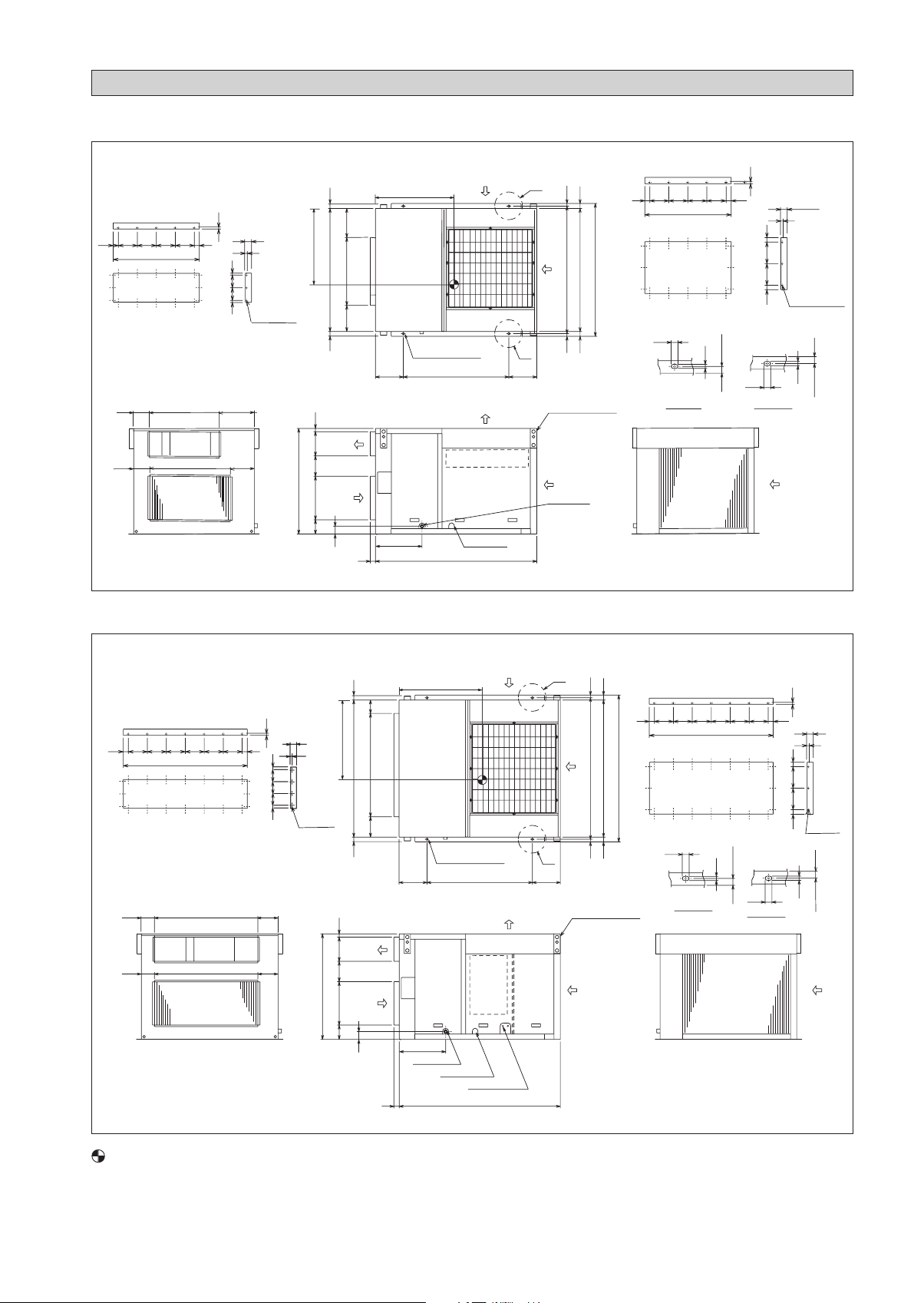
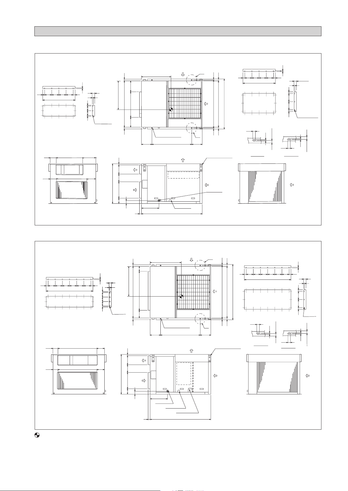
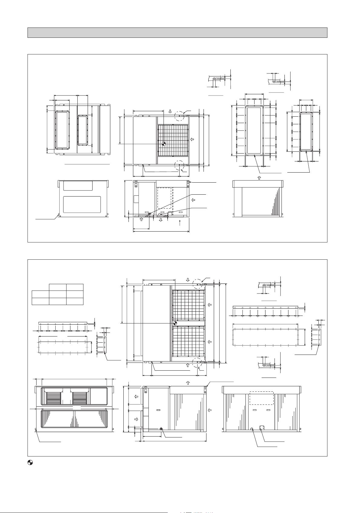
UAT(Y)(P)60A
OUTLINE AND DIMENSIONS
(unit ; mm)
* Except : Drain size. (unit ; inch)
20 150 150 150 150 20
668
Supply air duct flange
208
208
668 224
Supply air
668
Return air
10
49
10
24 125 125 24
16- ø3 Holes
224
1000
640
35
412 132 297
125
51 1100 51
Supply
air
Return
air
71
208
668
224
50
765
4-15X25 Mtg. holes
265 2651000
437
1530
Control box
Wiring hole
A
B
25
46
1142
1100
1192
25
46
Hanger (4 places)
Drain R1
34 150 150 150 150 34
668
Return air duct flange
25
15
(1342)
25
Detail B Detail A
Condenser
Air inlet
10
49
10
36 170 170 36
16- ø3 Holes
15
25
25
(1342)
UAT(Y)(P)80, 100, 120A
(1) Side flow
60 150 150 150 150 150 150 60
1020
Supply air duct flange
1020 173107
Supply air
1020
Return air
10
49
10
18.5 100 100 100 18.5
21- ø3
Holes
173107
1000
720
41135
337
75
412
1300 51
51
Supply
air
Return
air
71
107
173 1020
50
790
4-15X25 Mtg. holes
265 2651000
Control
box
437
Drain R1
Wiring hole
Check Joint
1530
A
B
25
46
1342
1300
1392
25
46
Hanger (4 places)
60 150 150 150 150 150 150 60
1020
Return air duct flange
25
15
Detail B
Condenser
Air inlet
(1342)
25
25
Detail A
10
49
10
36 170 170 36
20- ø3
25
15
(1342)
CENTER OF GRAVITY
i

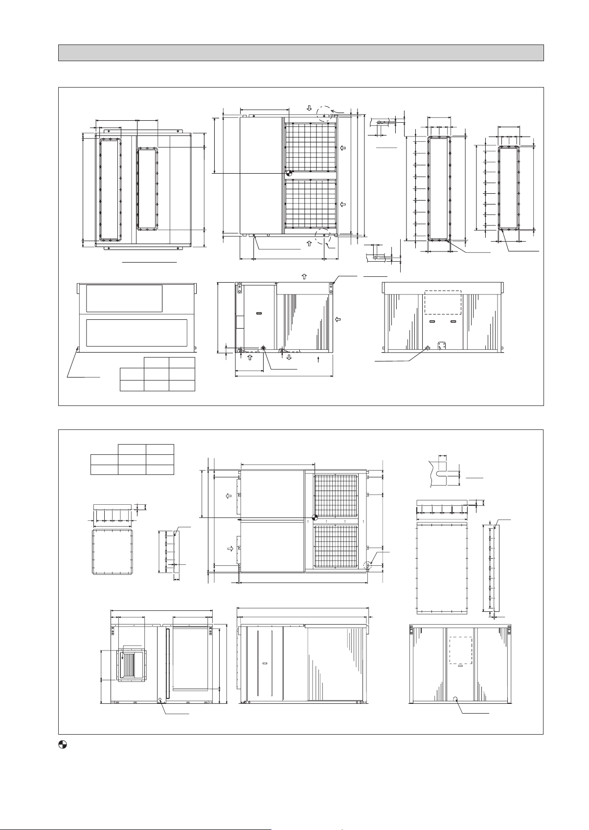
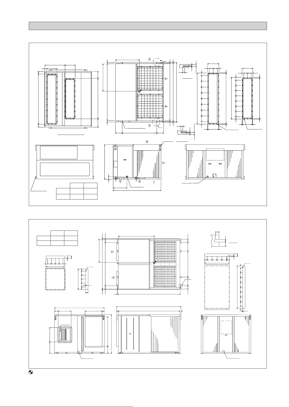
UAT(Y)(P)80, 100, 120A
OUTLINE AND DIMENSIONS
(2) Down fl ow
637
372
45
155
1058
Return air
87
*(4)RT80,
100A only
281
242
832
Supply air
226
View C (Bottom view)
720
51
1300
51
1000
71
265
Return air
437
790
4-15X25 Mtg. holes
1000
Control
box
9
9
Supply air
1530
A
B
265
C
25
Detail A
25
46
1300
1342
1392
25
46
Hanger (4 places)
Drain R 1
Wiring hole
372
140 46
Return air duct fl ange
19-ø3 Holes
Condenser
Air inlet
25
10
1038
10
10
Detail B
49
160160320
160160
49
15
(1342)
25
96
160160
832
160160
96
16-ø3 Holes
10
281
100 100
Supply air duct fl ange
261
4041
10
812
10
10
25
15
(1342)
140
46
49
160160160160160160
1058
49
368
10
UAT(Y)(P)150, 200A
(1) Side fl ow
AB
C.O 1670 1200
H.P 1800 1330
72 200 200 200 200 200 200 72
1744
Supply air duct flange
1744123
Supply
air
123
Return air
* C.O. only
1744
Return air
462
10
49
10
51 120 120 120 51
26- ø3
123
Holes
123
995
1200
51
1990
51
35462
151
428
124
960
123
1744
123
4-15X25 Mtg. holes
235 235
Supply
air
Return
air
483
77
50
Drain R1
B
A
Condenser
Air inlet
A
B
Hanger (4 places)
25
46
25
Detail A
72 200 200 200 200 200 200 200 200 72
1990
46
2032
25
2082
Condenser
Air inlet
1744
Return air Duct fl ange
25
Detail B
Control box
HP1
HP2
LP1
LP2
Check Joint
Wiring hole
15
15
25
(2032)
(2032)
25
Condenser
Air inlet
10
428
26-ø3 Holes
49
10
3434 120120120
CENTER OF GRAVITY
ii
UAT(Y)(P)150, 200A
OUTLINE AND DIMENSIONS
(2) Down flow
717
79
372
1041782
Return air
104
* C.O. only
359
Supply air
View C (Bottom view)
AB
RT-A 1670 1200
RT-AR 1800 1330
264294
1432
995
1200
1990
51 51
77
235
8
Return air
483
960
4-15X25 Mtg. holes
B
Condenser
Air inlet
Supply air
8
Drain R1
A
A
46
25
25
2082
2032
1990
25
46
25
B
235
Hanger
(4 places)
Detail B
C
15
Detail A
15
Condenser
Air inlet
Wiring hole
25
2032
1782
2032
25
46 46140140
91
20020020020020020020020091
10
372
Return air duct fl ange
368
Control box
l
10
10
180
1432
1762
180180180180
10
24-ø3 Holes
Condenser
Air inlet
120 120 59.559.5
86
180180
86
10 10
359
Supply air duct fl ange
339
22-ø3 Holes
10
1412
10
UAT(Y)(P)250, 300A
XY
250 1590 1020
300 1630 1020
12080120 120 120
43 43
Supply air
duct Flange
640510
10
566
165 100
566
Supply
air
640
2200
120 120 120 120 80
80
Drain R1
80
20-ø3
10
Return
air
758
25
144
Supply
Y
air
2200
1912
Return
air
25
23 2768
144
80
1302
1735
320
X
1146 383383144 144
A
2850
2720
Condenser
Air inlet
50
22.5
150 150 150 15080 80
758
Return air
duct fl ange
Condenser
Air inlet
15
27.5
Control
box
Wiring hole
Detail A
10
80
28-ø3
51
1302
150 150 150 150 150
150 150 150
10
51
Condenser
Air inlet
CENTER OF GRAVITY
iii
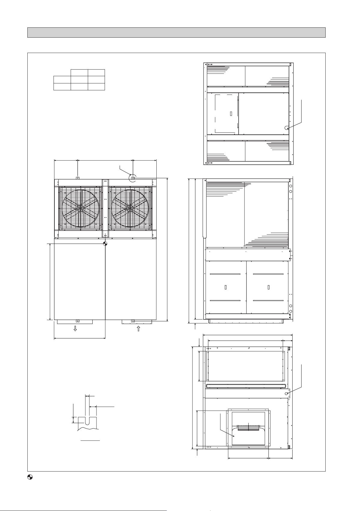
UAT(Y)(P)360, 420A
360 1730 1130
420 1800 1080
XY
OUTLINE AND DIMENSIONS
AIR INLET
CONDENSER
516 1220 516
X
BOX
CONTROL
AIR INLET
CONDENSER
A
AIR INLET
CONDENSER
3180
3148
3100
WIRING HOLE
SUPPLY
AIR
22.5
CENTER OF GRAVITY
Y
DETAIL A
RETURN
AIR
15
27.5
2252
80
100
660
782
62
SUPPLY AIR
1974
1650
AIR
RETURN
892 526
210
DRAIN 1"
iv

INSTALLATION MANUAL
This manual provides the procedures of installation to ensure a safe and good standard of operation for the air
conditioner unit.
Special adjustment may be necessary to suit local requirements.
Before using your air conditioner, please read this instruction manual carefully and keep it for future reference.
This appliance is intended to be used by expert or trained users in shops, in light industry and on farms, or for
commercial use by lay persons.
This appliance is not intended for use by persons, including children, with reduced physical, sensory or mental
capabilities, or lack of experience and knowledge, unless they have been given supervision or instruction concerning
use of the appliance by a person responsible for their safety.
Children should be supervised to ensure that they do not play with the appliance.
SAFETY PRECAUTIONS
English
Original Instruction
! WARNING
Installation and maintenance should be performed by
•
qualified persons who are familiar with local code
and regulation, and experienced with this type of
appliance.
All field wiring must be installed in accordance with
•
the national wiring regulation.
Ensure that the rated voltage of the unit corresponds
•
to that of the name plate before commencing wiring
work according to the wiring diagram.
The unit must be GROUNDED to prevent possible
•
hazard due to insulation failure.
All electrical wiring must not touch the refrigerant
•
piping, or any moving parts of the fan motors.
Confirm that the unit has been switched OFF before
•
installing or servicing the unit.
Disconnect from the main power supply before
•
servicing the air conditioner unit.
DO NOT pull out the power cord when the power is
•
ON. This may cause serious electrical shocks which
may result in fire hazards.
Keep the air-conditioner units, power cable and
•
transmission wiring, at least 1m from TVs and radios,
to prevent distorted pictures and static. (Depending on
the type and source of the electrical waves, static may
be heard even when more than 1m away).
IMPORTANT
ENGLISH
Important information regarding the refrigerant used
This product contains fluorinated greenhouse gases.
Do not vent gases into the atmosphere.
Refrigerant type: R407C
(1)
GWP
(1)
The refrigerant quantity is indicated on the unit name
plate.
Periodical inspections for refrigerant leaks may be required
depending on European or local legislation. Please contact
your local dealer for more information.
value:
GWP = global warming potential
1773.85
! CAUTION
Please take note of the following important points
when installing.
Do not install the unit where leakage of flammable
•
gas may occur.
If gas leaks and accumulates around the unit, it
may cause fire ignition.
Ensure that drainage piping is connected properly.
•
If the drainage piping is not connected properly, it
may cause water leakage which will dampen the
furniture.
Do not overcharge the unit.
•
This unit is factory pre-charged.
Overcharge will cause over-current or damage to
the compressor.
Ensure that the unit’s panel is closed after service
•
or installation.
Unsecured panels will cause the unit to operate
noisily.
Sharp edges and coil surfaces are potential locations
•
which may cause injury hazards.
Avoid from being in contact with these places.
Before turning off the power supply, set the remote
•
controller’s ON/OFF switch to the “OFF” position
to prevent the nuisance tripping of the unit. If this is
not done, the unit’s fans will start turning automatically
when power resumes, posing a hazard to service
personnel or the user.
Do not operate any heating apparatus too close to
•
the air conditioner unit.
Donʼt use joined and twisted wires for incoming
•
power supply.
The equipment is not intended for use in a potentially
•
explosive atmosphere.
NOTICE
Disposal Requirement
Dismantling of the unit, treatment of the refrigerant, oil and other parts must be done in accordance with the
applicable legislation.
1
INSTALLATION OF THE UNIT
1.1 Location For Installation
Install the unit in such way that air distributed by the unit cannot be drawn in again (as in the case of short circuit of discharge
air). Allow suffi cient space for maintenance around the unit.
When two or more units are installed in a location, they must be positioned such that one unit will not be taking the discharge
air from another unit.
Ensure that there is no obstruction of air fl ow into or out of the unit. Remove obstacles which block air intake or air
discharge.
The location must be well ventilated, so that the unit can draw and distribute plenty of air.
The unit is recommended to install in:-
A place capable of bearing the weight of the unit and isolating noise and vibration.
A place where has adequate drainage.
A place where the unit will not be buried in snow.
A place where air outlet port is not exposed to strong wind.
A place where the air discharge and operating sound level will not annoy the neighbours.
The location where it is not accessible by general public.
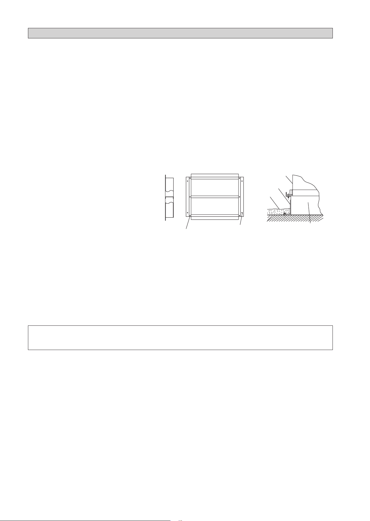
1.2 Unit Support
1. The fi gure shows the use of the roof curb for
mounting these units.
Roof curb
Unit
Seal with tar
Roof deck
2. The curb should be sealed and fi xed to the roof by
weather stripping. A suggested means of sealing
the unit and roof curb as shown in the left.
6 - ø15
Unit mounting holes
4 - ø15
Roof mounting holes
Roof curb
1.3 Duct Construction
These unit are equiped with supply and return air openings. Duct connection to the unit should be made with duct flanges
•
and secured directly to the air openings with flexible duct connectors to avoid normal noise transmission.
To prevent air leakage, all duct seams should be sealed.
•
Ducts in the spaces that not air-conditioned, must be insulated.
•
Ducts exposed to the outside must be weather proofed.
•
Ducts that entering building through the roof, the entering should be sealed with weather stripping to prevent the rain,
•
sand, dust etc. from entering the bulding.
Correct size of filter must be install at the return air duct.
•
! CAUTION
Do not install the unit at altitude over 2000m
2
INSTALLATION OF THE UNIT
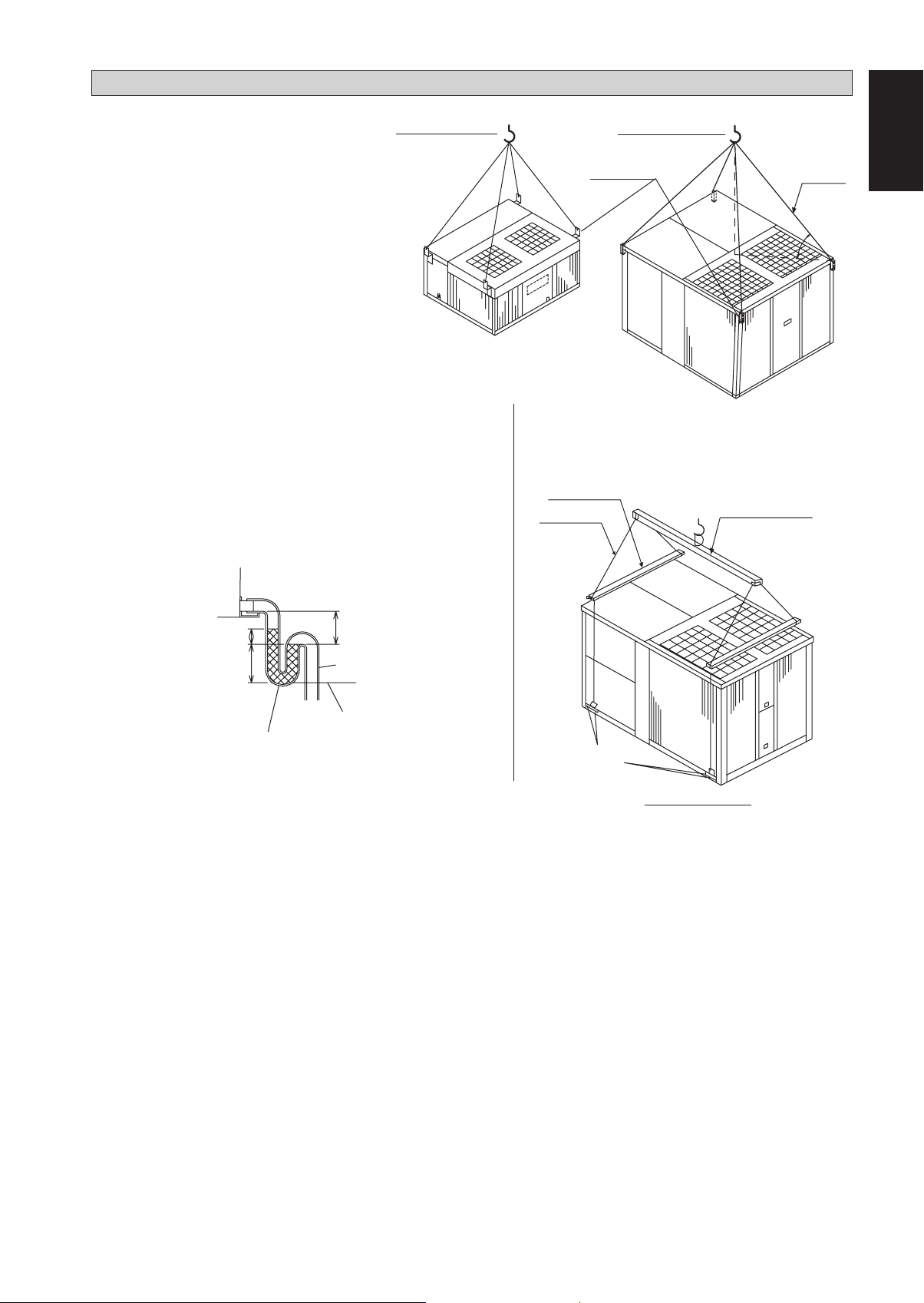
1.4 Unit Lifting
UAT(Y)(P)60~200A
Hanger brackets at 4 corner of the unit are
used for unit lifting purpose.
The angle A of the chain should be at least 45°,
and insulation should be added at 4 corner of
the chain to prevent the damage of the panel
when lifting.
1.5 Drain piping
A 1 FPT condensate drain fitting is provided. The drain pipe can
•
be led out at the front side.
The drain pipe must be provided with a trap on the outside of
•
the unit and also installed at an incline for proper drainage, as
shown in the right.
To prevent condensate formation and leakage, provide the drain
•
pipe with insulation to safeguard against sweating.
Upon completion of the piping work, check that there is no
•
leakage and that the water drains off properly.
The drain piping should have a drain trap.
Hanger Bracket
Spreader Bar
Chain
UAT(Y)(P)250, 300A
English
Chain
A
Lifting Beam
C
A
A 70mm
B 2C
C 2X ESP
Drain trap
B
The drain pipe
should extend
below this level.
Note: ESP = External Static Pressure
Drain trap for condensate
Drain piping
Lifting Holes for shackle
(4 corners)
UAT(Y)(P)360, 420A
3
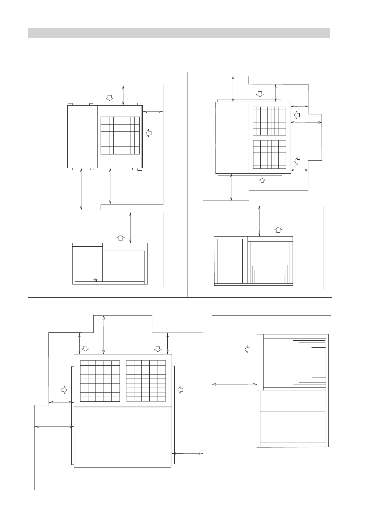
INSTALLATION OF THE UNIT
1.6 Space required around units (unit ; mm)
All space value ; minimum clearance
UAT(Y)(P)60, 80, 100, 120A
Evaporator coil,
air fi lter service
1000
Condenser
300
inlet
Electrical control
circuit & compressor
700
service
(min clearance)
Condenser
outlet
1500
300
UAT(Y)(P)150, 200A
Evaporator coil,
air fi lter service
Evaporator coil,
air fi lter service
1000
1000
(min clearance)
500
Condenser
inlet
(min clearance)
Condenser outlet
1500
Condenser
inlet
300
Electrical
300
700
control circuit
& compressor
service
UAT(Y)(P)250, 300, 360, 420A
1500
Condenser
(min clearance)
1000
2000
(min clearance)
Evaporator coil,
motor service
1000
inlet
Electrical control
circuit & compressor
service
1000
Condenser
inlet
1000
Condenser outlet
3000
(min clearance)
4
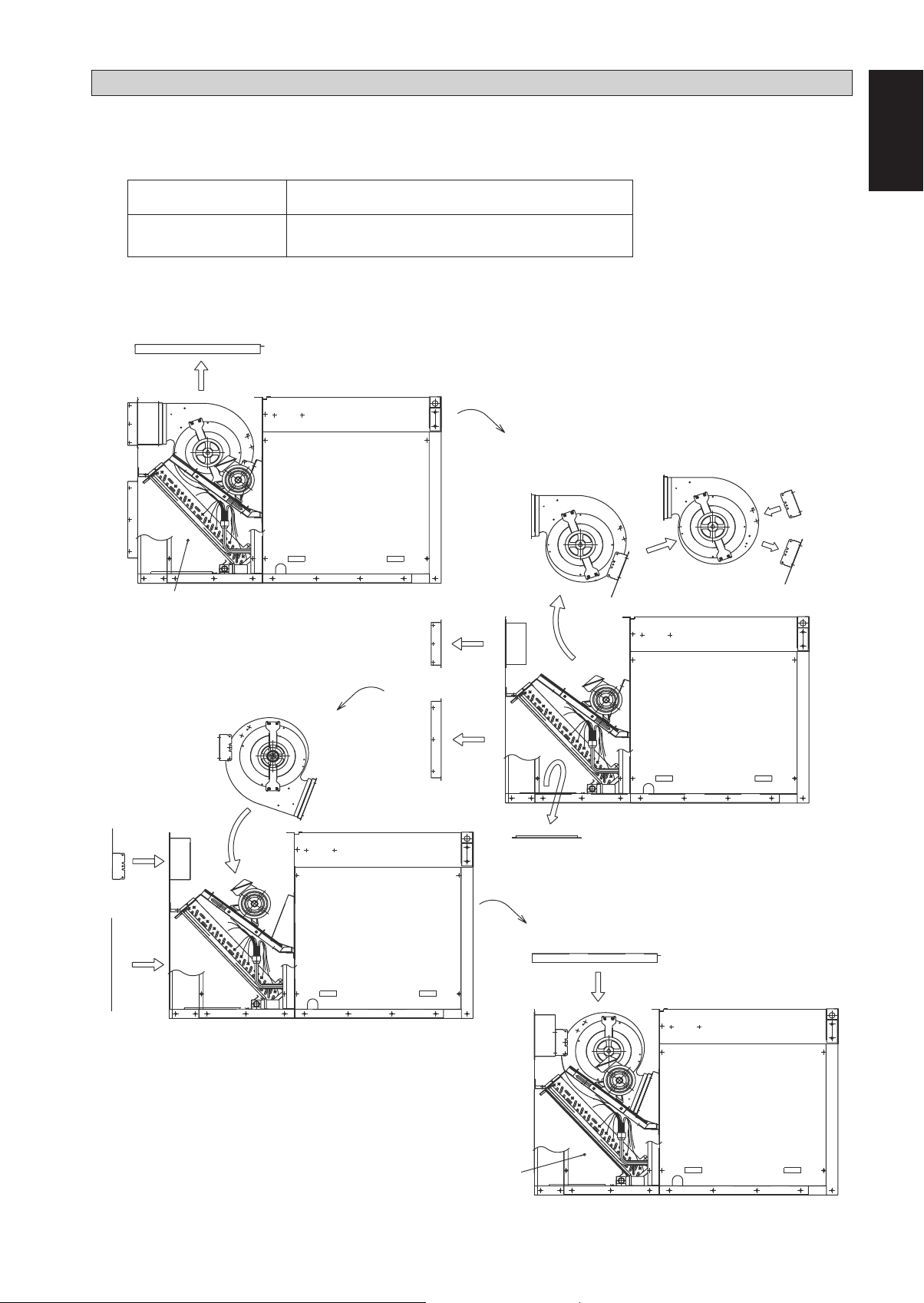
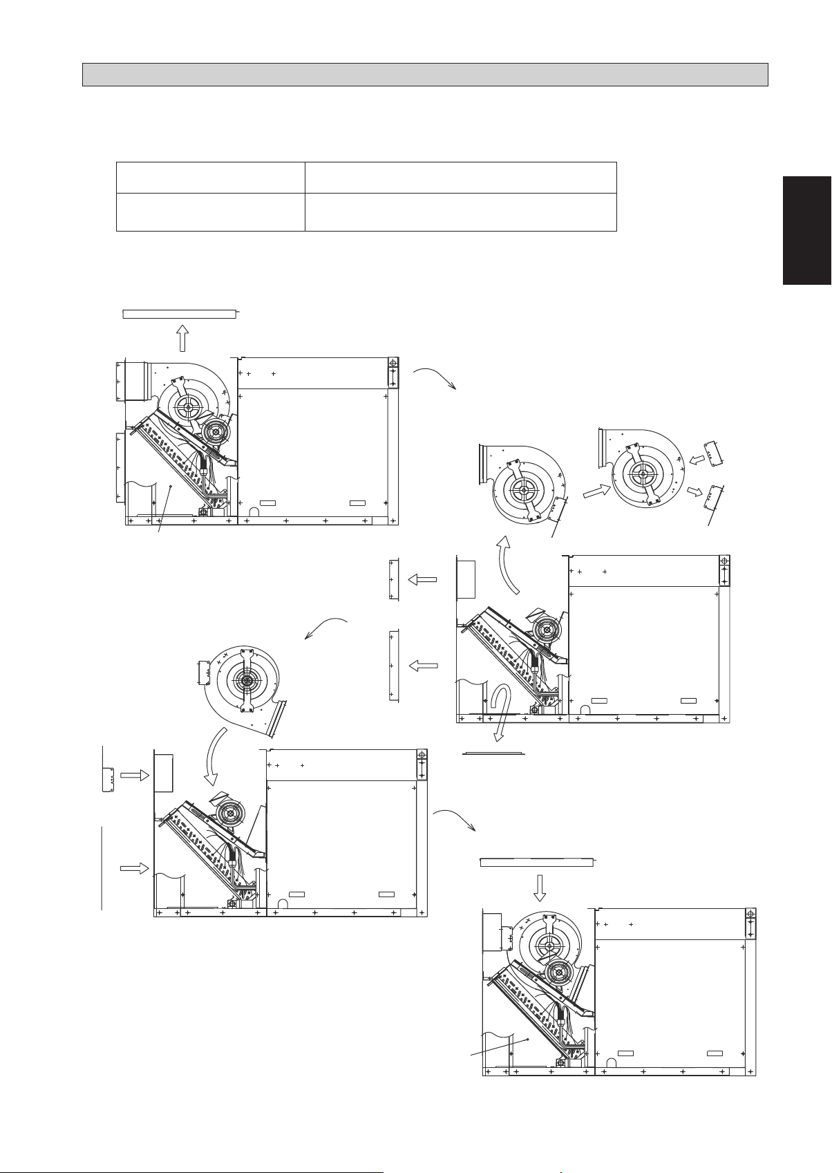
1.7 Unit conversion
INSTALLATION OF THE UNIT
Please check for accessory parts as below. (Packed in the unit, and available for convertible unit only)
1. Side inlet cover 1 piece
2. Casing leg
2 pieces UAT(Y)(P)80, 100, 120A
4 pieces UAT(Y)(P)150, 200A
In the case of converting to down fl ow unit, change according to the following steps.
STEP 1
Remove
top panel
STEP 2
2. Additional casing leg
(Accessory parts)
English
Remove
service panel
STEP 3
Re-install
supply air cover
Re-install
fan assy
Remove
duct fl ange
Remove
duct fl ange
Remove supply
air cover
Remove
Remove
low cover
STEP 4
Re-install
top panel
1. Additional side inlet cover
(Accessory parts)
Re-install
service panel
5
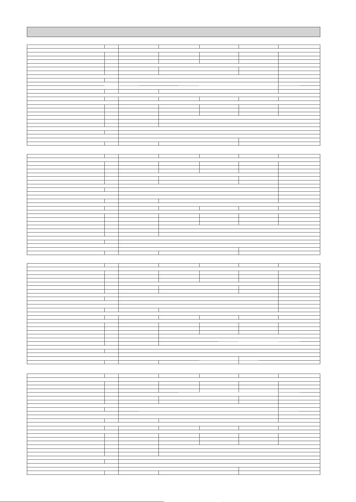
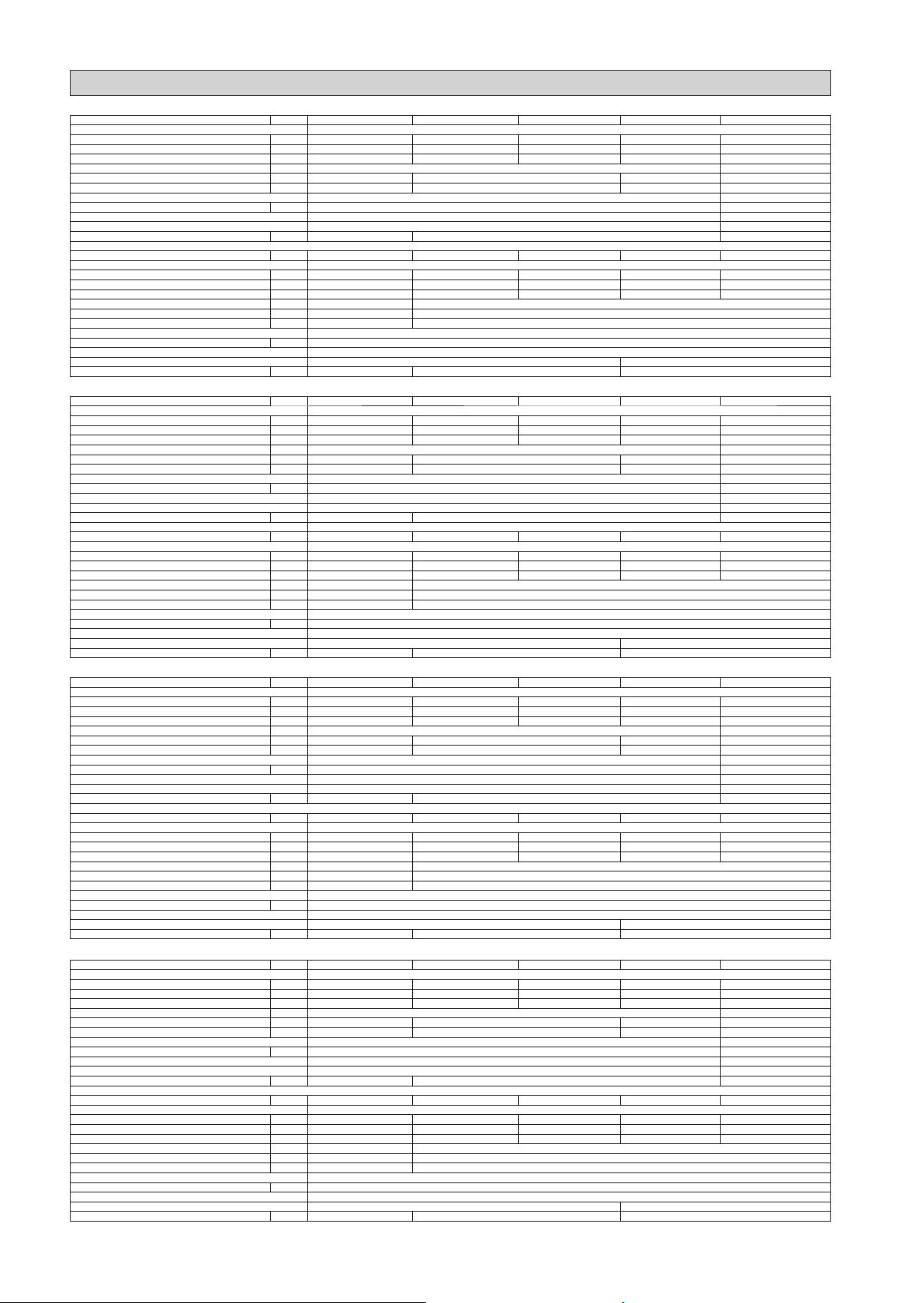
PHYSICAL DATA
COOLING ONLY (R22)
MODEL UAT60A UAT80A UAT100A UAT120A UAT150A
REFRIGERANT R22
REFRIGERANT CHARGE kg 5.2 4.0 5.9 6.2 4.5 x 2
EVAPORATOR AIR FLOW CFM 1800 2826 3532 3600 5651
EXTERNAL STATIC PRESSURE mmAq 10 20
CONDENSER AIR FLOW CFM 4500 5650 8000 11300
CONTROL SLM CONTROLLER SEQUENTIAL CONTROLLER
CONTROL WIRE LENGTH (STANDARD / MAX) : SIZE m : mm
COMPRESSOR (TYPE / QUANTITY) SCROLL / 1 SCROLL / 2
AIR FILTER (TYPE / QUANTITY) WASHABLE SARANET / 1 WASHABLE SARANET / 2
AIR FILTER DIMENSION (LENGTH x WIDTH x THICKNESS) mm 820 x 615 x 1 1020 x 615 x 1 840 x 667 x 1
MODEL UAT200A UAT250A UAT300A UAT360A UAT420A
REFRIGERANT R22
REFRIGERANT CHARGE kg 5.9 x 2 10.5 x 2 10.4 x 2 16.5 / 19.5 19.5 x 2
EVAPORATOR AIR FLOW CFM 6710 8000 9600 11000 12500
EXTERNAL STATIC PRESSURE mmAq 20 30
CONDENSER AIR FLOW CFM 11300 20000
CONTROL SEQUENTIAL CONTROLLER
CONTROL WIRE LENGTH (STANDARD / MAX) : SIZE m : mm
COMPRESSOR (TYPE / QUANTITY) SCROLL / 2
AIR FILTER (TYPE / QUANTITY) WASHABLE SARANET / 2 WASHABLE SARANET / 2 & 4
AIR FILTER DIMENSION (LENGTH x WIDTH x THICKNESS) mm 840 x 667 x 1 1370 x 735 x 1 860 x 550 & 600 x 4
HEAT PUMP (R22)
MODEL UATY60A UATY80A UATY100A UATY120A UATY150A
REFRIGERANT R22
REFRIGERANT CHARGE kg 4.5 4.7 5.6 6.0 4.7 x 2
EVAPORATOR AIR FLOW CFM 1800 2826 3532 3600 5651
EXTERNAL STATIC PRESSURE mmAq 10 20
CONDENSER AIR FLOW CFM 4500 5650 10000 11300
CONTROL SLM CONTROLLER SEQUENTIAL CONTROLLER
CONTROL WIRE LENGTH (STANDARD / MAX) : SIZE m : mm
COMPRESSOR (TYPE / QUANTITY) SCROLL / 1 SCROLL / 2
AIR FILTER (TYPE / QUANTITY) WASHABLE SARANET / 1 WASHABLE SARANET / 2
AIR FILTER DIMENSION (LENGTH x WIDTH x THICKNESS) mm 820 x 615 x 1 1020 x 615 x 1 840 x 667 x 1
MODEL UATY200A UATY250A UATY300A UATY360A UATY420A
REFRIGERANT R22
REFRIGERANT CHARGE kg 5.6 x 2 10.0 x 2 9.4 x 2 13.3 / 16.4 16.4 x 2
EVAPORATOR AIR FLOW CFM 6710 8000 9600 11000 12500
EXTERNAL STATIC PRESSURE mmAq 20 30
CONDENSER AIR FLOW CFM 11300 20000
CONTROL SEQUENTIAL CONTROLLER
CONTROL WIRE LENGTH (STANDARD / MAX) : SIZE m : mm
COMPRESSOR (TYPE / QUANTITY) SCROLL / 2
AIR FILTER (TYPE / QUANTITY) WASHABLE SARANET / 2 WASHABLE SARANET / 2 & 4
AIR FILTER DIMENSION (LENGTH x WIDTH x THICKNESS) mm 840 x 667 x 1 1370 x 735 x 1 860 x 505 & 600 x 4
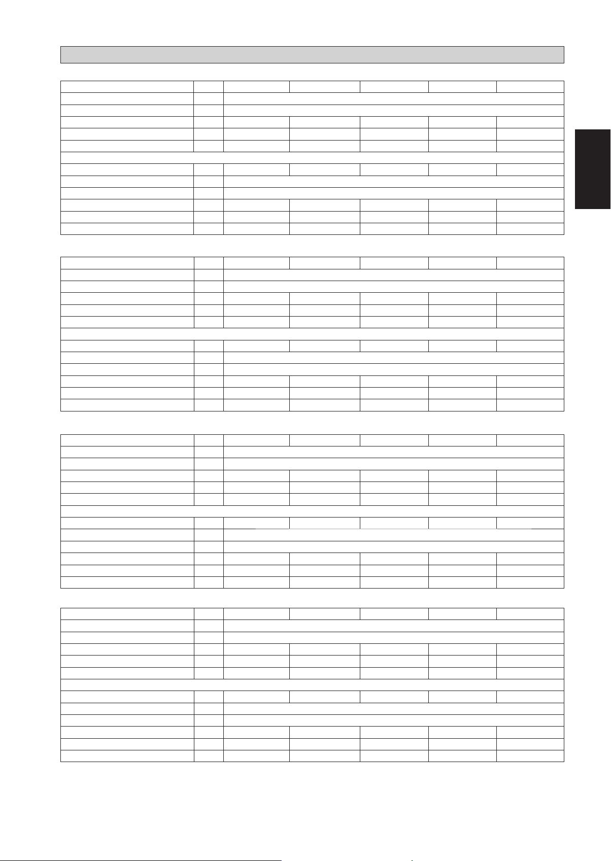
COOLING ONLY (R407C)
MODEL UATP60A UATP80A UATP100A UATP120A UATP150A
REFRIGERANT R407C
REFRIGERANT CHARGE kg 4.6 4.6 5.9 5.6 3.9 x 2
EVAPORATOR AIR FLOW CFM 1800 2826 3532 3600 5651
EXTERNAL STATIC PRESSURE mmAq 10 20
CONDENSER AIR FLOW CFM 4500 5650 8000 11300
CONTROL SLM CONTROLLER SEQUENTIAL CONTROLLER
CONTROL WIRE LENGTH (STANDARD / MAX) : SIZE m : mm
COMPRESSOR (TYPE / QUANTITY) SCROLL / 1 SCROLL / 2
AIR FILTER (TYPE / QUANTITY) WASHABLE SARANET / 1 WASHABLE SARANET / 2
AIR FILTER DIMENSION (LENGTH x WIDTH x THICKNESS) mm 820 x 615 x 1 1020 x 615 x 1 840 x 667 x 1
MODEL UATP200A UATP250A UATP300A UATP360A UATP420A
REFRIGERANT R407C
REFRIGERANT CHARGE kg 4.2 x 2 9.6 x 2 10.4 x 2 14.5 / 18.0 18.0 x 2
EVAPORATOR AIR FLOW CFM 6710 8000 9300 11000 12500
EXTERNAL STATIC PRESSURE mmAq 20 30
CONDENSER AIR FLOW CFM 11300 20000
CONTROL SEQUENTIAL CONTROLLER
CONTROL WIRE LENGTH (STANDARD / MAX) : SIZE m : mm
COMPRESSOR (TYPE / QUANTITY) SCROLL / 2
AIR FILTER (TYPE / QUANTITY) WASHABLE SARANET / 2 WASHABLE SARANET / 2 & 4
AIR FILTER DIMENSION (LENGTH x WIDTH x THICKNESS) mm 840 x 667 x 1 1370 x 735 x 1 860 x 505 & 600 x 4
HEAT PUMP (R407C)
MODEL UATYP60A UATYP80A UATYP100A UATYP120A UATYP150A
REFRIGERANT R407C
REFRIGERANT CHARGE kg 4.3 5.2 6.0 6.0 5.0 x 2
EVAPORATOR AIR FLOW CFM 1800 2826 3532 3600 5651
EXTERNAL STATIC PRESSURE mmAq 10 20
CONDENSER AIR FLOW CFM 4500 5650 10000 11300
CONTROL SLM CONTROLLER SEQUENTIAL CONTROLLER
CONTROL WIRE LENGTH (STANDARD / MAX) : SIZE m : mm
COMPRESSOR (TYPE / QUANTITY) SCROLL / 1 SCROLL / 2
AIR FILTER (TYPE / QUANTITY) WASHABLE SARANET / 1 WASHABLE SARANET / 2
AIR FILTER DIMENSION (LENGTH x WIDTH x THICKNESS) mm 820 x 615 x 1 1020 x 615 x 1 840 x 667 x 1
MODEL UATYP200A UATYP250A UATYP300A UATYP360A UATYP420A
REFRIGERANT R407C
REFRIGERANT CHARGE kg 5.8 x 2 9.4 x 2 9.6 x 2 13.5 / 16.0 16.0 x 2
EVAPORATOR AIR FLOW CFM 6710 8000 9300 11000 12500
EXTERNAL STATIC PRESSURE mmAq 20 30
CONDENSER AIR FLOW CFM 11300 20000
CONTROL SEQUENTIAL CONTROLLER
CONTROL WIRE LENGTH (STANDARD / MAX) : SIZE m : mm
COMPRESSOR (TYPE / QUANTITY) SCROLL / 2
AIR FILTER (TYPE / QUANTITY) WASHABLE SARANET / 2 WASHABLE SARANET / 2 & 4
AIR FILTER DIMENSION (LENGTH x WIDTH x THICKNESS) mm 840 x 667 x 1 1370 x 735 x 1 860 x 505 & 600 x 4
L/S 850 1334 1667 1699 2667
L/S 2124 2667 3776 5333
2
7 / 15 : 0.14 - / 100 : 0.14
L/S 3167 3776 4531 5191 5899
L/S 5333 9439
2
- / 100 : 0.14
L/S 850 1334 1667 1699 2667
L/S 2124 2667 4719 5333
2
7 / 15 : 0.14 - / 100 : 0.14
L/S 3167 3776 4531 5191 5899
L/S 5333 9439
2
- / 100 : 0.14
L/S 850 1334 1667 1699 2667
L/S 2124 2667 3776 5333
2
7 / 15 : 0.14 - / 100 : 0.14
L/S 3167 3776 4389 5191 5899
L/S 5333 9439
2
- / 100 : 0.14
L/S 850 1334 1667 1699 2667
L/S 2124 2667 4719 5333
2
7 / 15 : 0.14 - / 100 : 0.14
L/S 3167 3776 4531 5191 5899
L/S 5333 9439
2
- / 100 : 0.14
6

ELECTRICAL DATA
COOLING ONLY (R22)
MODEL UAT60A UAT80A UAT100A UAT120A UAT150A
POWER SUPPLY V/ph/Hz 400 / 3N ~ / 50
VOLTAGE RANGE
MAX CONTINUOUS CURRENT (COMP)
FULL LOAD CURRENT (FLA, COMP)
LOCKED ROTOR CURRENT (LRA, COMP)
MODEL UAT200A UAT250A UAT300A UAT360A UAT420A
POWER SUPPLY V/ph/Hz 400 / 3N ~ / 50
VOLTAGE RANGE
MAX CONTINUOUS CURRENT (COMP)
FULL LOAD CURRENT (FLA, COMP)
LOCKED ROTOR CURRENT (LRA, COMP)
HEAT PUMP (R22)
MODEL UATY60A UATY80A UATY100A UATY120A UATY150A
POWER SUPPLY V/ph/Hz 400 / 3N ~ / 50
VOLTAGE RANGE
MAX CONTINUOUS CURRENT (COMP)
FULL LOAD CURRENT (FLA, COMP)
LOCKED ROTOR CURRENT (LRA, COMP)
MODEL UATY200A UATY250A UATY300A UATY360A UATY420A
POWER SUPPLY V/ph/Hz 400 / 3N ~ / 50
VOLTAGE RANGE
MAX CONTINUOUS CURRENT (COMP)
FULL LOAD CURRENT (FLA, COMP)
LOCKED ROTOR CURRENT (LRA, COMP)
COOLING ONLY (R407C)
MODEL UATP60A UATP80A UATP100A UATP120A UATP150A
POWER SUPPLY V/ph/Hz 400 / 3N ~ / 50
VOLTAGE RANGE
MAX CONTINUOUS CURRENT (COMP)
FULL LOAD CURRENT (FLA, COMP)
LOCKED ROTOR CURRENT (LRA, COMP)
V
A 14.0 23.0 26.9 27.5 23.0 x 2
A 12.1 15.6 16.9 22.3 15.6 x 2
A 74 95 118 118 95 x 2
V
A 26.9 x 2
A
A
V
A 17.0 22.0 31.0 27.5 22.0 x 2
A 15.0 19.5 23.0 22.3 19.5 x 2
A 101 84 81 118 84 x 2
V
A 31.0 x 2
A
A
V
A 14.0 23.0 26.9 31.0 23.0 x 2
A 13.0 15.9 16.9 22.3 15.6 x 2
A 74 95 118 118 95 x 2
16.9 x 2 22.3 x 2 30.0 x 2 24.0, 30.0 30.0 x 2
118 x 2 118 x 2 174 x 2 175, 215 215 x 2
23.0 x 2 22.3 x 2 30.0 x 2 24.0, 30.0 30.0 x 2
81 x 2 118 x 2 174 x 2 175, 215 215 x 2
27.5 x 2 42.0 x 2
27.5 x 2 42.0 x 2
380 ~ 415
380 ~ 415
380 ~ 415
380 ~ 415
380 ~ 415
35.0, 50.0
35.0, 50.0
50.0 x 2
50.0 x 2
English
MODEL UATP200A UATP250A UATP300A UATP360A UATP420A
POWER SUPPLY V/ph/Hz 400 / 3N ~ / 50
VOLTAGE RANGE
MAX CONTINUOUS CURRENT (COMP)
FULL LOAD CURRENT (FLA, COMP)
LOCKED ROTOR CURRENT (LRA, COMP)
HEAT PUMP (R407C)
MODEL UATYP60A UATYP80A UATYP100A UATYP120A UATYP150A
POWER SUPPLY V/ph/Hz 400 / 3N ~ / 50
VOLTAGE RANGE
MAX CONTINUOUS CURRENT (COMP)
FULL LOAD CURRENT (FLA, COMP)
LOCKED ROTOR CURRENT (LRA, COMP)
MODEL UATYP200A UATYP250A UATYP300A UATYP360A UATYP420A
POWER SUPPLY V/ph/Hz 400 / 3N ~ / 50
VOLTAGE RANGE
MAX CONTINUOUS CURRENT (COMP)
FULL LOAD CURRENT (FLA, COMP)
LOCKED ROTOR CURRENT (LRA, COMP)
V
A 26.9 x 2
A
A
V
A 17.0 23.0 26.9 31.0 23.0 x 2
A 15.0 15.9 16.9 22.3 15.9 x 2
A 101 95 118 118 95 x 2
V
A 26.9 x 2
A
A
16.9 x 2 22.3 x 2 30.0 x 2 24, 30 30.0 x 2
118 x 2 118 x 2 174 x 2 175, 215 215 x 2
16.9 x 2 22.3 x 2 32.0 x 2 24, 30 30.0 x 2
118 x 2 118 x 2 174 x 2 175, 215 215 x 2
31.0 x 2 42.0 x 2
31.0 x 2 42.0 x 2
380 ~ 415
380 ~ 415
380 ~ 415
35.0, 50.0
35.0, 50.0
50.0 x 2
50.0 x 2
7
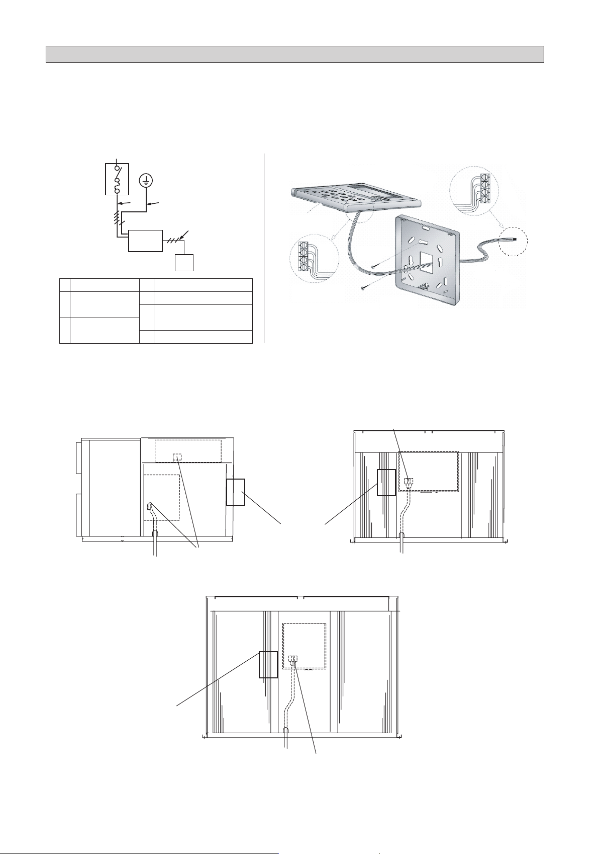
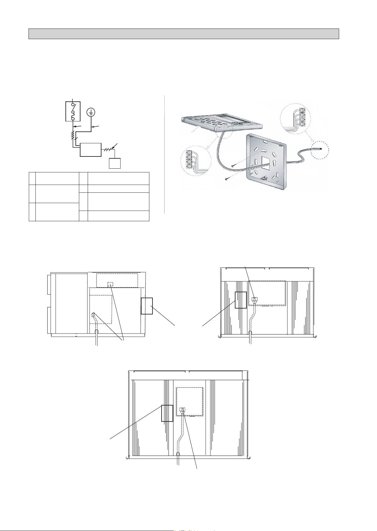
WIRE CONNECTION
All electrical work must be carried out by qualifi ed electrician and accordance with local supply requirement and associated
•
regulation.
Method for connecting electric wire
Before connecting the wire, consult the electric power company of jurisdiction.
1. The entire wiring diagram of unit.
a
b
PE
g
c
2. Remote control wire connection.
UAT(Y)(P)150, 200, 250, 300, 360, 420A
LCD Remote
(Top case)
f
d
GND
+5
B
A
remote control. Connect directly to connector 'CN2' on
mainboard.
a. Power supply
Main switch/fuse
b.
(fi eld supply)
Power supply
c.
wiring for unit
e
Unit
d.
e. Remote control
Connection wiring for
f.
unit & remote controller
g. Earth
Connection behind
Top case
Note: For UAT(Y)(P)60, 80, 100, 120A, wire is attached the
3. Wiring connection to unit
Remove the panel and connect the units power supply wires to terminal block, as shown below.
UAT(Y)(P)60, 80, 100, 120A
UAT(Y)(P)150, 200A
Terminal block
GND
+5
B
A
Connection at
Mainboard
Connection Wire
(fi eld supply)
UAT(Y)(P)60 only
Terminal block
Recommended
switch box position
Recommended
switch box
position
UAT(Y)(P)250, 300, 360, 420A
Terminal block
NOTE: While installing the circuit breaker onto the unit, make sure that the screws do not damage the components
(e.g. coil) inside of the unit.
The circuit breaker also can be installed without attaching to the unit.
8

5
N
2
3
4
OUTFAN2OUTFAN3 OUTFAN1
TRANSFORMER
NEUTRAL
DS1DS2DS3DS4
ROOM
ID4ID3ID2ID1
HP4HP3HP2HP1
ON/OFF
GND
A
5V
COMP1
COMP2
COMP3
COMP4
IN
FAN
HEATER1
HEATER2
4WV1
4WV2
4WV3
4WV4
OUTFAN 4
LIVE
B
NL3L2L1
1
UVW
A2
A1
RST
UVW
A2
A1
RST
UVW
A2
A1
RST
96
98
95
6
N
L3
L2
L1
R
U
T
R
E
S
E
T
6
8
5
2
W
2
1
T
L
N
N
1
O
U
T
F
A
N
2
O
U
T
F
A
N
1
R
O
O
M
I
D
4
1
2
2
NNN
R
E
S
E
T
6
8
5
2
W
2
1
T
E
WVU
RST
L
UVW
A2
A1
RST
RESET
96
98
95
62
UVW
A2
A1
RST
NNNN
N
TSR
NTS
R
WIRE CONNECTION
Arrangement of terminal block for controller are shown below.
CONTROL MODULE UAT(Y)(P)60A CONTROL MODULE UATY(P)150, 200A
PCB
X1 X2
PCB
F1
TB1
Connector for remote
control wires
UATY(P) only
52F1
T1
X1
X2
X3
51F1
Terminal Block for
power supply wires
C
TB2
52C
52F2
51C
UATY(P) only
52F
47
F1
662
47
51F1
51C1
52C252C1
51C2
TB1
NNLL33LL22LL1
Terminal Block for
power supply wires
TB2
NNNNNNN
UATY(P) only UATY(P) only
CONTROL MODULE UAT(Y)80, 100A, UAT(Y)(P)120A CONTROL MODULE UAT(P)150, 200A
Terminal Block for
power supply wires
FZ
52F1
52C
RRSST
RRSST
UUVVW
WWVVU
51C
TB1
PCB
N
L
UATY80, 100A
only
Connector for
remote control
wires
All except for
UATY80, 100A
X1
F1
TB1
AA1
AA2
X1
T
E
S
662
E
R
995
998
996
NNTTSSR
52F2
AA1
RRSST
UUVVW
AA2
X2
T
E
S
662
E
R
995
998
996
51C1
47
UATY(P) only
Terminal Block for
power supply wires
52C252C1
51C2
R
O
O
M
I
D
4
44WWVV1
44WWVV2
O
U
T
F
A
N
1
O
U
T
F
A
N
2
52F2 52F3
47
PCB
Connector for remote
control wires
Connector for
English
remote control
wires
LLIIVVE
CONTROL MODULE UATYP80, 100A CONTROL MODULE UAT(Y)(P)250A
F1
PCB
52C
52F1
52F2
51C
TB1
X1
51F1
TB2
Terminal Block for
power supply wires
CONTROL MODULE UAT(Y)(P)300A
Connector for remote
control wires
47
Connector
for remote
control wires
UATY(P) only
Terminal Block
for power supply
wires
CONTROL MODULE UAT(Y)(P)360, 420A
Connector
for remote
control wires
47
PCB
52C1
51C1
TB1
PCB
TB1
52C2
52F2
51C2
F1
52F
51F1
F1
Connector
for remote
control wires
52F1 &51F1
52F3
X2
X1
UATY(P) only
TB2&3
47
52F2
52C1
51C1
52C2
52F3
X1 X2
51C2
TB2 &3
Terminal Block for
power supply wires
Terminal Block for
power supply wires
UATY(P) only
9

WIRE CONNECTION
Wiring Example and Selection of Circuit Breaker 380 ~ 415V, 3N ~ /50
MODEL
POWER CABLE
(mm
2
)
UAT(Y)(P)60A 632 32 6
UAT(Y)(P)80A 632 32 6
UAT(Y)(P)100A 10 50 50 10
UAT(Y)(P)120A 10 50 50 10
UAT(Y)(P)150A 10 50 50 10
UAT(Y)(P)200A 16 63 63 16
UAT(Y)(P)250A 25 80 80 25
UAT(Y)(P)300A 35 100 100 35
UAT(Y)(P)360A 50 125 125 50
UAT(Y)(P)420A 50 125 125 50
Note:
A main switch or other means for disconnection, having a contact separation in all poles, must be incorporated in fi xed wiring in
accordance with local and national legislation.
The unit is to be wired directly from an electrical distribution board either by a circuit breaker (preferred) or HRC fuse.
•
Fix the power supply wiring to control module. Connect control wiring to control terminal block through the control box’s hole.
•
Earth wiring must be connected.
•
The power supply cord must be equivalent to H07RN-F which is the minimum requirement, and to be used in protective tube.
•
BREAKER
CAPACITY (A)
OVER CURRENT
PROTECTION SWITCH (A)
EARTH CABLE
(mm2 over)
Before working on this unit, isolate from the power supply.
! WARNING
•
Electrical wiring to this unit and the remote controller shall be installed in accordance with the appropriate
•
requirements of the local wiring code.
OPERATING RANGE
Ensure the operating temperature is in allowable range.
Cooling (R22)
Cooling Only Unit
52
50
40
30
19
10
0
Outdoor temp. (°C DB)
15 24
20 3010 25
Indoor temp. (°C WB) Indoor temp. (°C WB)
Cooling (R407C)
Cooling Only Unit & Cooling Mode For Heat Pump Model
50
46
40
30
19
10
0
Outdoor temp. (°C DB)
15 24
15 20 3010 25
Indoor temp. (°C WB)
Cooling Mode For Heat Pump Model
50
46
40
30
19
10
0
Outdoor temp. (°C DB)
20
18
15
10
5
0
-5
-9
Outdoor temp. (°C WB)
Cooling (R22)
15 24
15 20 3010 25
Heat pump
Heat Pump Unit Only
••••••••••
15 27
20 3010 25
Indoor temp. (°C DB)
! CAUTION:
The use of your air conditioner
outside the range of working
temperature and humidity can
result in serious failure.
10
SPECIAL PRECAUTIONS WHEN DEALING WITH R407C UNIT
No additional charge of compressor oil is permitted.
R407C is a zeotropic refrigerant mixture which has zero
•
ozone depletion potential and thus conformed to Montreal
Protocol regulation. It requires Polyester oil (POE) oil
for its compressor's lubricant. Its refrigerant capacity and
performance are about the same as the refrigerant R22.
•
POE or PVE oil is used as lubricant for R407C compressor,
which is different from the mineral oil used for R22
compressor. During installation or servicing, extra precaution
must be taken not to expose the R407C system too long
to moist air. Residual POE or PVE oil in the piping and
components can absorb moisture from the air.
Refrigerant R407C is more easily affected by dust of
•
moisture compared with R22, make sure to temporarily
cover the ends of the tubing prior to installation.
•
No other refrigerant other than R407C.
•
Tools specifically for R407C only (must not be used for
•
R22 or other refrigerant)
Manifold gauge and charging hose
i)
Gas leak detector
ii)
Refrigerant cylinder / charging cylinder
iii)
Vacuum pump c/w adaptor
iv)
Flare tools
v)
Refrigerant recovery machine
vi)
Filter-dryer must be installed along the liquid line for
•
all R407C air conditioners. This is to minimise the
contamination of moisture and dirt in the refrigerant
system. Filter-dryer must be of molecular sieve type. For
a heat-pump system, install a two-way flow filter-dryer
along the liquide line.
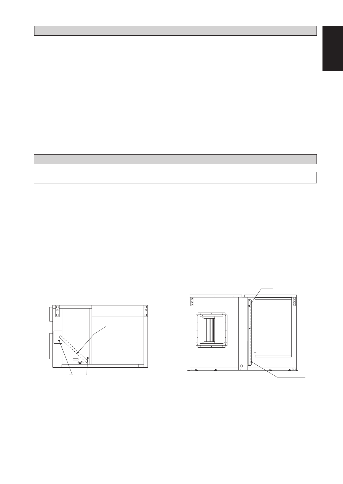
SERVICE AND MAINTENANCE
Note is valid for Turkey only: The lifetime of our products is ten (10) years
SERVICE OF THE FILTER
Remove any dust adhering to the filter by using a vacuum cleaner or wash in lukewarm water (below 40°C) with a
•
neutral cleaning detergent.
Rinse the filter well and dry before placing it back onto the unit.
•
Do not use gasoline, volatile substances or chemicals to clean the filter.
•
Clean the filter at least once every 2 weeks. Or more frequently if neccesary.
•
English
Filter Position
The fi lters are mounted in front of the indoor heat exchanger.
* (Air fi lter : special order or fi eld supply)
UAT(Y)(P)60, 80, 100, 120, 150, 200A UAT(Y)(P)250, 300, 360, 420A
Filter
Filter cover
removed when servicing
note: both side for unit 150, 200A
Service panel
Filter
Filter cover
removed when servicing
11
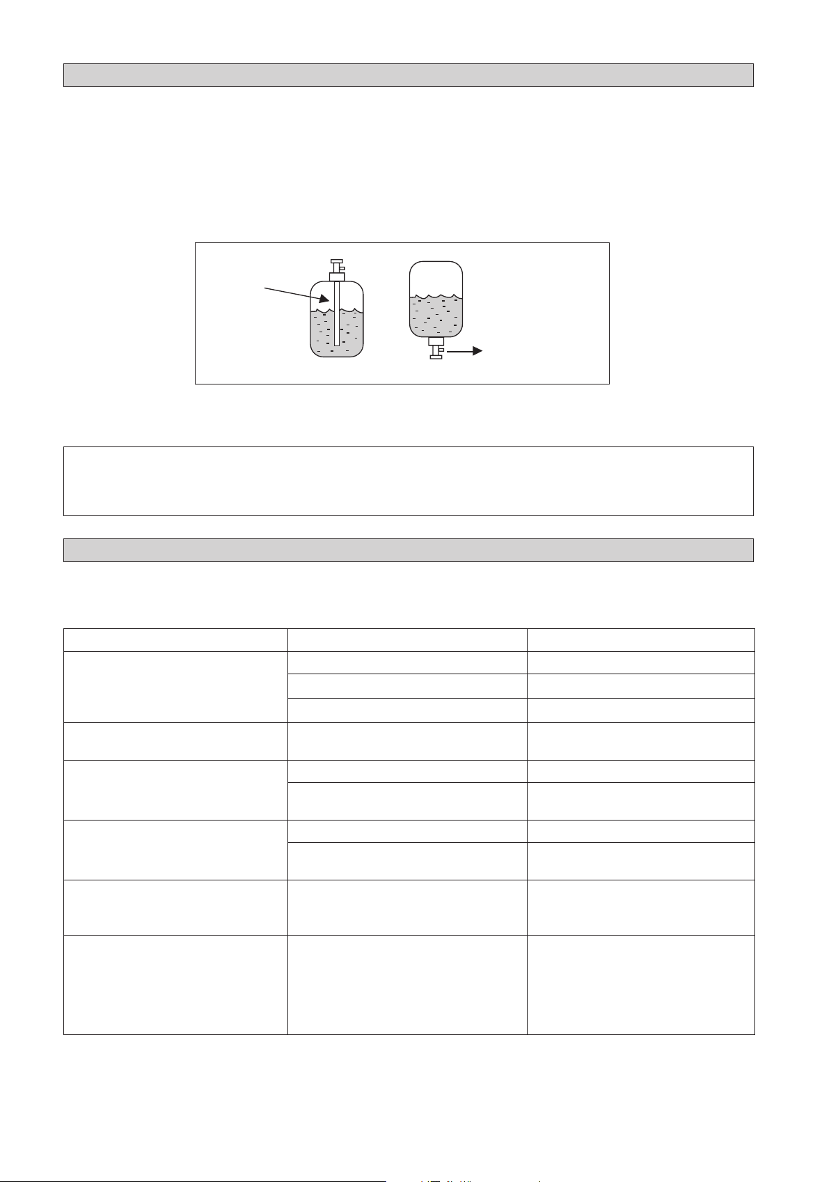
VACUUMING AND CHARGING
The rooftop package units are factory pre-charged with suffi cient refrigerant. However, there may be a need for charge recovery
during service and maintenance works. Therefore, some precautions must be taken to ensure optimum and trouble-free system
operation:
(i) The system should be throughly vacuumed to ensure no incompressible gas and moisture in the system.
(ii) Use a vacuum pump for R22 or R407C exclusively. Using the same vacuum pump for different refrigerants may damage
the vacuum pump or the unit.
(iii) The refrigerant should never be released directly into the environment.
(iv) When charging R407C, ensure that only liquid is being withdrawn from the cylinder or can.
Invert cylinder
Dip-pipe
Normally, the R407C cylinder or can is being equipped with a dip-pipe for liquid withdrawal. However, if the dip-pipe is
not available, invert the cylinder or can so as to withdraw liquid from the valve at the bottom.
without dip-pipe
Liquid
withdrawal
! CAUTION
Do not top-up when servicing leak, as this will reduce the unit performance. Vacuum the unit thoroughly and then
•
charge the unit with fresh R22 & R407C according to the amount recommended in the specifi cation.
TROUBLESHOOTING
If any malfunction of the air conditioner unit is noted for some simple trouble-shooting tips. Check the following
fault conditions and causes for some simple troubleshooting tips. For any enquiries on spare part, please contact you
authorized dealer.
Problem Causes Action
Unit does not run. Power failure. Press the [ON/OFF] after power restore.
Fuse blown or circuit breaker tripped. Replace fuse or reset circuit breaker.
Power supply wiring phase incorrect. Modify the wiring phase.
Compressor does not operate in 3 min
after unit has started.
Air fl ow is low. Filter is fi lled with dust and dirt. Clean the fi lter.
Compressor operate continuously. Dirty air fi lter. Clean the air fi lter.
No cool air delivered during cooling
cycle, or no hot air delivered during
heating cycle.
On heating cycle, indoor fan stop
suddenly.
UAT(Y)(P)60, 80, 100, 120A
On heating cycle, delivered air does not
warm enough suddenly.
UAT(Y)(P)150, 200, 250, 300, 360, 420A
Protection against frequent starting. Wait for 3 min for the compressor to start.
There are some obstacles at the air inlet or
outlet of the units.
Temperature setting is too low (for cooling).
Temperature setting is too high (for heating).
Temperature setting is too high (for cooling).
Temperature setting is too low (for heating).
Unit is in defrosting cycle. Wait for a while.
Remove obstacles.
Reset the temperature.
Set the temperature lower.
Set the temperature higher.
(It will be resumed after defrosting.)
If the fault persists, please call your authorized local dealer/serviceman.
12
UAT(Y)(P)60A
CONTOUR ET DIMENSIONS
(unité ; mm)
* Sauf : Taille de drain. (unité ; pouce)
10
20 150 150 150 150 20
668
Bride du conduit d’air
d’admission
208
208
668 224
Admission
d’air
668
Reprise d’air
49
10
24 125 125 24
Trous 16-ø3
224
1000
640
51 1100 51
35125 412 132 297
Admission
d’air
Reprise
d’air
765
208
668
224
Trous de montage
437
4-15X25
1000
Boîtier de commande
Orifice de câblage
1530
265 265
71
50
A
25
1142
25
B
Suspension (4 points)
Drain R 1
46
1100
46
34 150 150 150 150 34
1192
Bride du conduit d’air
25
668
de retour
Détail B Détail A
Admission d’air
du condensateur
10
49
10
36 170 170 36
Trous 16-ø3
15
(1342)
25
25
25
15
(1342)
UAT(Y)(P)80, 100, 120A
(1) Débit latéral
60 150 150 150 150 150 150 60
Bride du conduit d’air d’admission
1020
1020 173107
Admission
1020
Reprise d’air
d’air
10
49
10
18,5 100 100 100 18,5
Trous 21-ø3
173107
1000
720
51 1300 51
41135
Admission
d’air
75 337
Reprise
412
d’air
71
107
173 1020
50
790
Trous de montage
265 2651000
4-15X25
437
Drain R1
Orifice de câblage
Boîtier de
commande
Vérifier le joint
1530
A
25
1342
25
B
Suspension (4 points)
46
60 150 150 150 150 150 150 60
1300
1392
46
1020
Bride du conduit d’air
de retour
25
15
Détail B
Admission
d’air du
condensateur
(1342)
25
25
Détail A
10
49
10
36 170 170 36
20- ø3
25
15
(1342)
CENTRE DE GRAVITÉ
i
UAT(Y)(P)80, 100, 120A
CONTOUR ET DIMENSIONS
(2) Débit inférieur
637
372
45
155
1058
Reprise d’air
87
Vue C (Vue de dessous)
*(4)RT80,
100A
uniquement
281
242
832
Admission d’air
226
720
51
1300
51
1000
71
Reprise d’air
790
Trous de montage 4-15X25
265
437
1000
9
Admission d’air
Boîtier de
commande
9
1530
A
B
265
Suspension (4 points)
Drain R 1
Orifice de câblage
C
25
1342
25
46
1300
46
25
Détail A
1392
25
15
(1342)
140
46
49
160160160160160160
1058
49
368
10
Admission d’air du
condensateur
25
Détail B
372
140 46
49
10
160160320
1038
de retour
10
10
19-Trous 16-ø3
160160
49
Bride du conduit d’air
15
(1342)
25
96
160160
832
160160
96
10
16-Trous 16-ø3
281
4041
100 100
10
812
Bride du conduit d’air
d’admission
10
261
10
UAT(Y)(P)150, 200A
(1) Débit latéral
AB
C.O 1670 1200
H.P 1800 1330
72 200 200 200 200 200 200 72
1744
Bride du conduit d’air
d’admission
1744123
Admission
d’air
123
Reprise d’air
* C.O. uniquement
1744
Reprise d’air
10
49
10
51 120 120 120 51
Trous 26-ø3
123
123
995
1200
51
123
1990
1744
123
51
35462151428124
Admission
d’air
Reprise
d’air
960
us de montage 4-15X25
Tro
235 235
483
77
50
B
Drain R 1
A
Admission
d’air du
condensateur
A
25
46
1990
2032
46
25
B
Suspension (4 points)
25
15
25
72 200 200 200 200 200 200 200 200 72
2082
Bride du conduit d’air
de retour
25
Boîtier de
Admission
d’air du
condensateur
commande
HP1
LP1
Orifice de câblage
Détail A
1744
15
Détail B
HP2
LP2
Vérifier le joint
(2032)
26-Trous 16-ø3
25 (2032)
Admission
d’air du
condensateur
10
428
10
34
120120120
34
49
CENTRE DE GRAVITÉ
ii
UAT(Y)(P)150, 200A
CONTOUR ET DIMENSIONS
(2) Débit inférieur
717
79
372
1041782
Reprise d’air
104
Vue C (Vue de dessous)
* C.O. uniquement
RT-A 1670 1200
RT-AR 1800 1330
359
Admission d’air
AB
264294
1432
995
1200
1990
51 51
77
960
Trous de montage 4-15X25
235
8
Reprise d’air
483
B
8
Drain R1
A
Admission
d’air du
condensateur
Admission
d’air
A
46
25
25
2082
2032
1990
25
46
25
B
235
Étrier
(4 points)
Détail B
C
Orifice de câblage
Détail A
25
15
2032
1782
15
2032
25
Admission
d’air du
condensateur
46 46140140
91
20020020020020020020020091
10
Boîtier de
commande
372
10
1432
1762
Bride du conduit d’air
de retour
10
368
10
24-Trous 16-ø3
l
Admission
d’air du
condensateur
120120 59,559,5
86
180
180180
180180180180
86
10 10
359
10
1412
Bride du conduit d’air
d’admission
10
339
22-Trous 16-ø3
UAT(Y)(P)250, 300A
XY
250 1590 1020
300 1630 1020
566
165
Admission
d’air
10
566
12080120 120 120
43 43
Bride du
conduit d’air
d’admission
640510
640
2200
120 120 120 120 80
80
80
Drain R1
20-ø3
10
758
Reprise
d’air
Y
25
144
Admission
d’air
2200
1912
Reprise
d’air
25
23 2768
144
80
100
1302
1735
320
X
1146 383383144 144
A
2850
2720
Admission
d’air du
condensateur
50
22,5
150 150 150 15080 80
758
Bride du conduit d’air
de retour
Boîtier
Admission
d’air du
condensateur
de
commande
15
Détail A
27,5
80
10
1302
Admission
d’air du
condensateur
Orifice de câblage
51
51
150 150 150 150 150
150 150 150
28-ø3
10
CENTRE DE GRAVITÉ
iii

UAT(Y)(P)360, 420A
CONTOUR ET DIMENSIONS
XY
360 1730 1130
420 1800 1080
516 1220 516
A
D’AIR DU
ADMISSION
BOÎTIER DE
COMMANDE
D’AIR DU
ADMISSION
D’AIR DU
ADMISSION
CONDENSATEUR
ORIFICE DE CÂBLAGE
CONDENSATEUR
CONDENSATEUR
X
ADMISSION
D’AIR
Y
15
22,5
DESSIN DÉTAILLÉ A
27,5
REPRISE
D’AIR
3148
3180
2252
3100
80
782
100
660
D’AIR
ADMISSION
1974
1650
D’AIR
REPRISE
210
ÉVACUATION 1"
CENTRE DE GRAVITÉ
62
892 526
iv
MANUEL D’INSTALLATION
Ce manuel fournit les procédures d’installation pour assurer le bon fonctionnement et la sécurité de cet appareil.
Des ajustements peuvent être nécéssaires pour suivre les réglementations locales.
Avant d’installer et de faire fonctionner le climatiseur, lisez attentivement ce manuel et conservez le.
Cet appareil est destiné à être utilisé par des utilisateurs experts ou formés dans les magasins, dans l’industrie légère
ou dans les fermes, oupour un usage commercial par des personnes non spécialisées.
Cet appareil n'est pas destiné à être utilisé par des personnes, y compris les enfants, souffrant de capacités physiques,
sensorielles ou mentales réduites, ou accusant un manque d'expérience et de connaissances, sauf si elles sont supervisées
ou ont reçu des instructions concernant l'emploi de cet appareil d'une personne responsable de leur sécurité.
Les enfants doivent être supervisés pour s'assurer qu'ils ne jouent pas avec l'appareil.
PRÉCAUTIONS DE SÉCURITÉ
Français
! ATTENTION
L’installation et la maintenance doivent être exécutées
•
par une personne qualifiée qui est familiarisée avec les
lois et réglementations en vigueur, et aussi expérimentée
dans ce type d’équipements.
Tous les câblages doivent répondre aux réglementations
•
électriques nationales.
Avant de commencer le raccordement suivant le
•
schéma électrique, s’assurer que la tension nominale
de l’appareil corresponde bien à celle indiquée sur la
plaque signalétique.
L’unité doit être raccordée à la TERRE pour
•
prévenir tous les risques possibles dûes à un défaut
d’isolation.
Les fils électriques ne doivent en aucun cas être en
•
contact avec les tuyaux de réfrigérant ou les parties
mobiles des moteurs du ventilateur.
Avant l’installation ou l’entretien du climatiseur,
•
s’assurer que l’appareil est éteint (OFF).
Débrancher l’appareil du circuit d’alimentation secteur
•
avant de procéder à l’entretien du climatiseur.
NE PAS retirer le câble d’alimentation électrique
•
de la prise quand l’appareil est sous branché. Il peut
en résulter des décharges électriques importantes
susceptibles de provoquer un incendie.
Les unités du climatiseur, le câble d’alimentation et
•
le câblage de transmission doivent être éloignés d’au
moins 1m des téléviseurs et radios, ce afin d’éviter les
interférences et les parasites. (En fonction du type et de la
source des ondes électriques, des parasites peuvent être
entendus même avec une distance supérieure à 1m).
IMPORTANT
FRANÇAIS
Information importante relative au réfrigérant
utilisé
Ce produit contient des gaz fluorés. Ne pas laisser les gaz
s’échapper dans l’atmosphère.
Type de réfrigérant : R407C
Valeur GWP
(1)
GWP = potentiel de réchauffement global
La quantité de réfrigérant est indiquée sur la plaque
signalétique de l’unité.
Des inspections périodiques de fuites de réfrigérant peuvent
être exigées en fonction de la législation européenne ou
locale. Veuillez contacter votre distributeur local pour plus
d’informations.
(1)
: 1773,85
! AVERTISSEMENT
Vérifier les points suivants au cours de l’installation.
Ne pas installer l’appareil où il peut se produire des
•
fuites de gaz inflammable.
En cas de fuite et accumulation de gaz autour de
l’appareil, il y a risque d’incendie.
S’assurer que le tuyau d’évacuation du condensat
•
est correctement branché.
Si le tuyau d’évacuation n’est pas correctement
branché, les éventuelles fuites d’eau risquent de
mouiller le mobilier.
Ne pas surcharger l’unité (en fluide frigorigène).
•
Cet appareil est préchargé en usine.
Une charge trop importante risque de provoquer
une surcharge électrique ou d’endommager le
compresseur.
S’assurer que le panneau supérieur de l’appareil est
•
remis en place après l’installation ou l’entretien.
Avec un panneau mal fixé l’appareil va fonctionner
bruyamment.
Les bords coupants et les surfaces du refroidisseur
•
tuulaire présentent un risque de blessure.
Mieux vaut éviter le contact avec ces endroits.
Avant de couper l’alimentation électrique, veiller à
•
ce que l’interrupteur ON/OFF de la télécommande
soit en position « OFF » afin d’éviter une mise en
marche intempestive de l’appareil. Si l’interrupteur
de la télécommande n’est pas en position « OFF »,
les ventilateurs de l’appareil se mettront en marche
dès que l’alimentation électrique est rétablie. Il peut
en résulter un danger pour le personnel d’entretien ou
l’utilisateur.
Ne pas utiliser d’appareil de chauffage trop près du
•
climatiseur.
N’utilisez pas de câbles joints et torsadés pour
•
l’alimentation électrique entrante.
•
L’équipement n’est pas conçu pour une utilisation
dans une atmosphère potentiellement explosive.
Traduction des instructions d’origine
AVIS
Instructions relatives à la mise au rebus
Le démontage de l’appareil et le traitement du réfrigérant, de l’huile et d’autres composants doivent être effectués
en accord avec les réglementations en vigueur.
1

INSTALLATION DE L’UNITÉ
1.1 Emplacement des unités
Installer l’unité de telle manière que l’air chaud qu’elle dégage ne puisse être repris par un autre appareil (interférence d’air
chaud). Prévoir un espace suffisant autour de l’appareil pour faciliter l’entretien.
Quand on installe deux unités ou plus dans un même endroit, elles doivent être positionnées de manière à ce qu’une unité ne
prenne pas l’air extrait d’une autre.
S’assurer qu’il n’y a pas d’obstruction sur le passage de l’air aspiré et refoulé de l’appareil. Retirer tout obstacle qui
pourrait bloquer la reprise ou le refoulement d’air.
L’emplacement doit être bien ventilé de manière à ce que l’appareil distribue la totalité de l’air à un niveau de température
plus bas.
Recommandations concernant le lieu d’installation de l’unité:L’emplacement doit pouvoir supporter le poids de l’unité et isoler le bruit et les vibrations.
L’évacuation doit être adéquate.
L’unité ne doit pas pouvoir être ensevelie par la neige.
Le port de sortie d’air ne doit pas être soumis à des vents violents.
Le bruit de l’air et du fonctionnement de l’appareil ne doit pas gêner les voisins.
Le public ne doit pas pouvoir accéder à l’unité.
1.2 Support de l’unité
1. Le schéma montre comment utiliser la margelle
du toit pour le montage de ces unités.
Margelle
Unité
Étanchéité
goudronnée
Toiture
2. La margelle doit être scellée et fixée sur le toit
grâce à de la bande d’étanchéité. Les moyens
suggérés de sceller l’unité et le toit limitent
comme montré dans la gauche.
6 - ø15
Trous de montage de l’appareil
4 - ø15
Trous de montage du toit
Margelle
1.3 Construction du conduit
Les unités sont équipées d’orifices d’admission et de reprise d’air. Le raccordement du conduit à l’unité doit être réalisé
•
avec les brides de conduit et directement fixé aux orifices d’aération avec des connecteurs de conduits flexibles afin
d’éviter une transmission de bruit anormale.
Pour éviter toute fuite d’air, tous les raccords de conduits doivent être soudés.
•
Les conduits installés dans des espaces non climatisés doivent être isolés.
•
Les conduits exposés à l’extérieur doivent être rendus étanches.
•
Pour les conduits pénétrant dans le bâtiment par le toit, l’entrée doit être rendue étanche grâce à de la bande d’étanchéité
•
afin d’éviter que la pluie, le sable, la poussière, etc. ne pénètrent dans le bâtiment.
Un filtre de taille adaptée doit être installé sur le conduit de reprise d’air.
•
! AVERTISSEMENT
Ne pas installer l’appareil à plus de 2000m d’altitude
2

INSTALLATION DE L’UNITÉ
1.4 Levage de l’unité
UAT(Y)(P)60~200A
Des parenthèses de levage de cintre d’unité au
coin 4 de l’unité sont utilisées pour le but de
levage d’unité.
L’angle A de la chaîne devrait être au moins 45°
et l’isolation devrait être ajoutée au coin 4 de la
chaîne pour empêcher les dommages du panneau
en se soulevant.
1.5 Tuyauterie d’évacuation
A 1 FPT Un raccord d’évacuation des condensats à filetage
•
gaz 1po est fourni. Le tuyau d’évacuation peut être dirigé sur
la face avant.
Le tuyau d’évacuation doit être fourni avec un siphon sur
•
l’extérieur de l’unité et doit également respecter une inclinaison
permettant une bonne évacuation, comme indiqué sur la
droite.
Pour éviter la formation de condensats et les fuites, isoler le tuyau
•
d’évacuation afin d’éviter tout suintement.
Après avoir terminé l’installation de la tuyauterie, contrôler
•
l’absence de fuites et la bonne évacuation de l’eau.
UAT(Y)(P)250, 300A
Ferrure de suspension
Palonnier
Chaîne
Chaîne
A
Français
Poutre de levage
La tuyauterie d’évacuation doit comporter un siphon.
C
A
A 70mm
B 2C
C 2X ESP
Siphon
B
Tuyauterie d’évacuation
Le tuyau
d’évacuation
doit se prolonger
endessous de ce
niveau.
Remarque : ESP = Pression statique externe
Siphon pour les condensats
Orifices de levage pour
les chaînes
(4 coins)
UAT(Y)(P)360, 420A
3

INSTALLATION DE L’UNITÉ
1.6 Espace requis autour de l’unité (unité ; mm)
Valeur de tout espace ; minimum de dégagement
UAT(Y)(P)60, 80, 100, 120A
Serpentin
évaporateur,
service de fi ltre
d’air
1000
Orifi ce
d’admission du
300
condensateur
300
Accès au circuit
de commande
700
électrique et accès au
compresseur
(dégagement minimum)
Orifi ce de
sortie du
condensateur
1500
UAT(Y)(P)150, 200A
Serpentin
évaporateur,
service de fi ltre
d’air
Serpentin
évaporateur,
service de fi ltre
d’air
1000
1000
(dégagement minimum)
Orifi ce
d’admission du
500
condensateur
300
700
Accès au circuit
Orifi ce d’admission
du condensateur
(dégagement minimum)
Orifi ce de sortie du
condensateur
1500
300
de commande
électrique et accès
au compresseur
UAT(Y)(P)250, 300, 360, 420A
1000
Orifi ce d’admission
1000
2000
Serpentin
évaporateur, le
du condensateur
service moteur
(dégagement minimum)
(dégagement minimum)
1500
Accès au circuit
de commande
électrique et accès au
compresseur
1000
Orifi ce
d’admission
du
1000
condensateur
Orifi ce de sortie
3000
(dégagement minimum)
du condensateur
4
INSTALLATION DE L’UNITÉ
1.7 Conversion des unités
Veuillez vérifi er la présence des accessoires cidessous. (Livrés avec l’unité et disponibles uniquement pour unité
convertible).
1. Couvercle d’entrée latérale 1 pièce
2. Pied de boîtier
2 pièce UAT(Y)(P)80, 100, 120A
4 pièce UAT(Y)(P)150, 200A
Pour convertir l'unité pour que le débit soit orienté vers le bas, suivez les étapes suivantes.
ÉTAPE 1
Retirer le panneau
supérieur
ÉTAPE 2
Retirer le panneau de
service
Retirer le
bride de
conduite
Retirez
Français
2. Pied de boîtier
supplémentaire
(Pièce accessoire)
Retirez le couvercle de
fourniture d’air
ÉTAPE 3
Réinstallez le
couvercle de
fourniture d’air
1. Couvercle latéral
d’entrée supplémentaire
(Pièce accessoire)
Réinstallez
l’ensemble
ventilateur
Retirer le
bride de
conduite
Retirez le couvercle
inférieur
ÉTAPE 4
Réinstallez le panneau
supérieur
Réinstallez le
panneau de
service
5
CARACTÉRISTIQUES PHYSIQUES
REFROIDISSEMENT SEULEMENT (R22)
MODÈLE UAT60A UAT80A UAT100A UAT120A UAT150A
RÉFRIGÉRANT R22
CHARGE DE FLUIDE FRIGORIGÈNE kg 5,2 4,0 5,9 6,2 4,5 x 2
DÉBIT D’AIR DE L’ÉVAPORATEUR CFM 1800 2826 3532 3600 5651
PRESSION STATIQUE EXTERNE mmAq 10 20
DÉBIT D’AIR DU CONDENSATEUR CFM 4500 5650 8000 11300
COMMANDE DISPOSITIF DE COMMANDE SLM DISPOSITIF DE COMMANDE SÉQUENTIEL
LONGUEUR DU CÂBLE DE COMMANDE (STANDARD/MAX) : TAILLE m : mm
COMPRESSEUR (TYPE/QUANTITÉ) SPIRALE/1 SPIRALE/2
FILTRE À AIR (TYPE/QUANTITÉ) TYPE SARANET LAVABLE/1 TYPE SARANET LAVABLE/2
DIMENSIONS DU FILTRE À AIR (LONGUEUR x LARGEUR x ÉPAISSEUR) mm 820 x 615 x 1 1020 x 615 x 1 840 x 667 x 1
MODÈLE UAT200A UAT250A UAT300A UAT360A UAT420A
RÉFRIGÉRANT R22
CHARGE DE FLUIDE FRIGORIGÈNE kg 5,9 x 2 10,5 x 2 10,4 x 2 16,5 / 19,5 19,5 x 2
DÉBIT D’AIR DE L’ÉVAPORATEUR CFM 6710 8000 9600 11000 12500
PRESSION STATIQUE EXTERNE mmAq 20 30
DÉBIT D’AIR DU CONDENSATEUR CFM 11300 20000
COMMANDE DISPOSITIF DE COMMANDE SÉQUENTIEL
LONGUEUR DU CÂBLE DE COMMANDE (STANDARD/MAX) : TAILLE m : mm
COMPRESSEUR (TYPE/QUANTITÉ) SPIRALE/2
FILTRE À AIR (TYPE/QUANTITÉ) TYPE SARANET LAVABLE/2 TYPE SARANET LAVABLE / 2 & 4
DIMENSIONS DU FILTRE À AIR (LONGUEUR x LARGEUR x ÉPAISSEUR) mm 840 x 667 x 1 1370 x 735 x 1 860 x 550 & 600 x 4
POMPE À CHALEUR (R22)
MODÈLE UATY60A UATY80A UATY100A UATY120A UATY150A
RÉFRIGÉRANT R22
CHARGE DE FLUIDE FRIGORIGÈNE kg 4,5 4,7 5,6 6,0 4,7 x 2
DÉBIT D’AIR DE L’ÉVAPORATEUR CFM 1800 2826 3532 3600 5651
PRESSION STATIQUE EXTERNE mmAq 10 20
DÉBIT D’AIR DU CONDENSATEUR CFM 4500 5650 10000 11300
COMMANDE DISPOSITIF DE COMMANDE SLM DISPOSITIF DE COMMANDE SÉQUENTIEL
LONGUEUR DU CÂBLE DE COMMANDE (STANDARD/MAX) : TAILLE m : mm
COMPRESSEUR (TYPE/QUANTITÉ) SPIRALE/1 SPIRALE/2
FILTRE À AIR (TYPE/QUANTITÉ) TYPE SARANET LAVABLE/1 TYPE SARANET LAVABLE/2
DIMENSIONS DU FILTRE À AIR (LONGUEUR x LARGEUR x ÉPAISSEUR) mm 820 x 615 x 1 1020 x 615 x 1 840 x 667 x 1
MODÈLE UATY200A UATY250A UATY300A UATY360A UATY420A
RÉFRIGÉRANT R22
CHARGE DE FLUIDE FRIGORIGÈNE kg 5,6 x 2 10,0 x 2 9,4 x 2 13,3 / 16,4 16,4 x 2
DÉBIT D’AIR DE L’ÉVAPORATEUR CFM 6710 8000 9600 11000 12500
PRESSION STATIQUE EXTERNE mmAq 20 30
DÉBIT D’AIR DU CONDENSATEUR CFM 11300 20000
COMMANDE DISPOSITIF DE COMMANDE SÉQUENTIEL
LONGUEUR DU CÂBLE DE COMMANDE (STANDARD/MAX) : TAILLE m : mm
COMPRESSEUR (TYPE/QUANTITÉ) SPIRALE/2
FILTRE À AIR (TYPE/QUANTITÉ) TYPE SARANET LAVABLE/2 TYPE SARANET LAVABLE / 2 & 4
DIMENSIONS DU FILTRE À AIR (LONGUEUR x LARGEUR x ÉPAISSEUR) mm 840 x 667 x 1 1370 x 735 x 1 860 x 505 & 600 x 4
REFROIDISSEMENT SEULEMENT (R407C)
MODÈLE UATP60A UATP80A UATP100A UATP120A UATP150A
RÉFRIGÉRANT R407C
CHARGE DE FLUIDE FRIGORIGÈNE kg 4,6 4,6 5,9 5,6 3,9 x 2
DÉBIT D’AIR DE L’ÉVAPORATEUR CFM 1800 2826 3532 3600 5651
PRESSION STATIQUE EXTERNE mmAq 10 20
DÉBIT D’AIR DU CONDENSATEUR CFM 4500 5650 8000 11300
COMMANDE DISPOSITIF DE COMMANDE SLM DISPOSITIF DE COMMANDE SÉQUENTIEL
LONGUEUR DU CÂBLE DE COMMANDE (STANDARD/MAX) : TAILLE m : mm
COMPRESSEUR (TYPE/QUANTITÉ) SPIRALE/1 SPIRALE/2
FILTRE À AIR (TYPE/QUANTITÉ) TYPE SARANET LAVABLE/1 TYPE SARANET LAVABLE/2
DIMENSIONS DU FILTRE À AIR (LONGUEUR x LARGEUR x ÉPAISSEUR) mm 820 x 615 x 1 1020 x 615 x 1 840 x 667 x 1
MODÈLE UATP200A UATP250A UATP300A UATP360A UATP420A
RÉFRIGÉRANT R407C
CHARGE DE FLUIDE FRIGORIGÈNE kg 4,2 x 2 9,6 x 2 10,4 x 2 14,5 / 18,0 18,0 x 2
DÉBIT D’AIR DE L’ÉVAPORATEUR CFM 6710 8000 9300 11000 12500
PRESSION STATIQUE EXTERNE mmAq 20 30
DÉBIT D’AIR DU CONDENSATEUR CFM 11300 20000
COMMANDE DISPOSITIF DE COMMANDE SÉQUENTIEL
LONGUEUR DU CÂBLE DE COMMANDE (STANDARD/MAX) : TAILLE m : mm
COMPRESSEUR (TYPE/QUANTITÉ) SPIRALE/2
FILTRE À AIR (TYPE/QUANTITÉ) TYPE SARANET LAVABLE/2 TYPE SARANET LAVABLE / 2 & 4
DIMENSIONS DU FILTRE À AIR (LONGUEUR x LARGEUR x ÉPAISSEUR) mm 840 x 667 x 1 1370 x 735 x 1 860 x 505 & 600 x 4
POMPE À CHALEUR (R407C)
MODÈLE UATYP60A UATYP80A UATYP100A UATYP120A UATYP150A
RÉFRIGÉRANT R407C
CHARGE DE FLUIDE FRIGORIGÈNE kg 4,3 5,2 6,0 6,0 5,0 x 2
DÉBIT D’AIR DE L’ÉVAPORATEUR CFM 1800 2826 3532 3600 5651
PRESSION STATIQUE EXTERNE mmAq 10 20
DÉBIT D’AIR DU CONDENSATEUR CFM 4500 5650 10000 11300
COMMANDE DISPOSITIF DE COMMANDE SLM DISPOSITIF DE COMMANDE SÉQUENTIEL
LONGUEUR DU CÂBLE DE COMMANDE (STANDARD/MAX) : TAILLE m : mm
COMPRESSEUR (TYPE/QUANTITÉ) SPIRALE/1 SPIRALE/2
FILTRE À AIR (TYPE/QUANTITÉ) TYPE SARANET LAVABLE/1 TYPE SARANET LAVABLE/2
DIMENSIONS DU FILTRE À AIR (LONGUEUR x LARGEUR x ÉPAISSEUR) mm 820 x 615 x 1 1020 x 615 x 1 840 x 667 x 1
MODÈLE UATYP200A UATYP250A UATYP300A UATYP360A UATYP420A
RÉFRIGÉRANT R407C
CHARGE DE FLUIDE FRIGORIGÈNE kg 5,8 x 2 9,4 x 2 9,6 x 2 13,5 / 16,0 16,0 x 2
DÉBIT D’AIR DE L’ÉVAPORATEUR CFM 6710 8000 9300 11000 12500
PRESSION STATIQUE EXTERNE mmAq 20 30
DÉBIT D’AIR DU CONDENSATEUR CFM 11300 20000
COMMANDE DISPOSITIF DE COMMANDE SÉQUENTIEL
LONGUEUR DU CÂBLE DE COMMANDE (STANDARD/MAX) : TAILLE m : mm
COMPRESSEUR (TYPE/QUANTITÉ) SPIRALE/2
FILTRE À AIR (TYPE/QUANTITÉ) TYPE SARANET LAVABLE/2 TYPE SARANET LAVABLE / 2 & 4
DIMENSIONS DU FILTRE À AIR (LONGUEUR x LARGEUR x ÉPAISSEUR) mm 840 x 667 x 1 1370 x 735 x 1 860 x 505 & 600 x 4
L/S 850 1334 1667 1699 2667
L/S 2124 2667 3776 5333
2
7 / 15 : 0,14 - / 100 : 0,14
L/S 3167 3776 4531 5191 5899
L/S 5333 9439
2
- / 100 : 0,14
L/S 850 1334 1667 1699 2667
L/S 2124 2667 4719 5333
2
7 / 15 : 0,14 - / 100 : 0,14
L/S 3167 3776 4531 5191 5899
L/S 5333 9439
2
- / 100 : 0.14
L/S 850 1334 1667 1699 2667
L/S 2124 2667 3776 5333
2
7 / 15 : 0,14 - / 100 : 0,14
L/S 3167 3776 4389 5191 5899
L/S 5333 9439
2
- / 100 : 0,14
L/S 850 1334 1667 1699 2667
L/S 2124 2667 4719 5333
2
7 / 15 : 0,14 - / 100 : 0,14
L/S 3167 3776 4531 5191 5899
L/S 5333 9439
2
- / 100 : 0,14
6
CARACTÉRISTIQUES ÉLECTRIQUES
REFROIDISSEMENT SEULEMENT (R22)
MODÈLE UAT60A UAT80A UAT100A UAT120A UAT150A
ALIMENTATION ÉLECTRIQUE V/ph/Hz 400 / 3N ~ / 50
TENSION D’ALIMENTATION V 380 ~ 415
COURANT CONTINU MAXI (COMP) A 14,0 23,0 26,9 27,5 23,0 x 2
INTENSITÉ DE PLEINE CHARGE (FLA, COMP) A 12,1 15,6 16,9 22,3 15,6 x 2
INTENSITÉ À ROTOR BLOQUÉ (LRA, COMP) A 74 95 118 118 95 x 2
MODÈLE UAT200A UAT250A UAT300A UAT360A UAT420A
ALIMENTATION ÉLECTRIQUE V/ph/Hz 400 / 3N ~ / 50
TENSION D’ALIMENTATION V 380 ~ 415
COURANT CONTINU MAXI (COMP) A 26,9 x 2 27,5 x 2 42,0 x 2 35,0, 50,0 50,0 x 2
INTENSITÉ DE PLEINE CHARGE (FLA, COMP) A 16,9 x 2 22,3 x 2 30,0 x 2 24,0, 30,0 30,0 x 2
INTENSITÉ À ROTOR BLOQUÉ (LRA, COMP) A 118 x 2 118 x 2 174 x 2 175, 215 215 x 2
POMPE À CHALEUR (R22)
MODÈLE UATY60A UATY80A UATY100A UATY120A UATY150A
ALIMENTATION ÉLECTRIQUE V/ph/Hz 400 / 3N ~ / 50
TENSION D’ALIMENTATION V 380 ~ 415
COURANT CONTINU MAXI (COMP) A 17,0 22,0 31,0 27,5 22,0 x 2
INTENSITÉ DE PLEINE CHARGE (FLA, COMP) A 15,0 19,5 23,0 22,3 19,5 x 2
INTENSITÉ À ROTOR BLOQUÉ (LRA, COMP) A 101 84 81 118 84 x 2
MODÈLE UATY200A UATY250A UATY300A UATY360A UATY420A
ALIMENTATION ÉLECTRIQUE V/ph/Hz 400 / 3N ~ / 50
TENSION D’ALIMENTATION V 380 ~ 415
COURANT CONTINU MAXI (COMP) A 31,0 x 2 27,5 x 2 42,0 x 2 35,0, 50,0 50,0 x 2
INTENSITÉ DE PLEINE CHARGE (FLA, COMP) A 23,0 x 2 22,3 x 2 30,0 x 2 24,0, 30,0 30,0 x 2
INTENSITÉ À ROTOR BLOQUÉ (LRA, COMP) A 81 x 2 118 x 2 174 x 2 175, 215 215 x 2
Français
REFROIDISSEMENT SEULEMENT (R407C)
MODÈLE UATP60A UATP80A UATP100A UATP120A UATP150A
ALIMENTATION ÉLECTRIQUE V/ph/Hz 400 / 3N ~ / 50
TENSION D’ALIMENTATION V 380 ~ 415
COURANT CONTINU MAXI (COMP) A 14,0 23,0 26,9 31,0 23,0 x 2
INTENSITÉ DE PLEINE CHARGE (FLA, COMP) A 13,0 15,9 16,9 22,3 15,6 x 2
INTENSITÉ À ROTOR BLOQUÉ (LRA, COMP) A 74 95 118 118 95 x 2
MODÈLE UATP200A UATP250A UATP300A UATP360A UATP420A
ALIMENTATION ÉLECTRIQUE V/ph/Hz 400 / 3N ~ / 50
TENSION D’ALIMENTATION V 380 ~ 415
COURANT CONTINU MAXI (COMP) A 26,9 x 2 31,0 x 2 42,0 x 2 35,0, 50,0 50,0 x 2
INTENSITÉ DE PLEINE CHARGE (FLA, COMP) A 16,9 x 2 22,3 x 2 30,0 x 2 24, 30 30,0 x 2
INTENSITÉ À ROTOR BLOQUÉ (LRA, COMP) A 118 x 2 118 x 2 174 x 2 175, 215 215 x 2
POMPE À CHALEUR (R407C)
MODÈLE UATYP60A UATYP80A UATYP100A UATYP120A UATYP150A
ALIMENTATION ÉLECTRIQUE V/ph/Hz 400 / 3N ~ / 50
TENSION D’ALIMENTATION V 380 ~ 415
COURANT CONTINU MAXI (COMP) A 17,0 23,0 26,9 31,0 23,0 x 2
INTENSITÉ DE PLEINE CHARGE (FLA, COMP) A 15,0 15,9 16,9 22,3 15,9 x 2
INTENSITÉ À ROTOR BLOQUÉ (LRA, COMP) A 101 95 118 118 95 x 2
MODÈLE UATYP200A UATYP250A UATYP300A UATYP360A UATYP420A
ALIMENTATION ÉLECTRIQUE V/ph/Hz 400 / 3N ~ / 50
TENSION D’ALIMENTATION V 380 ~ 415
COURANT CONTINU MAXI (COMP) A 26,9 x 2 31,0 x 2 42,0 x 2 35,0, 50,0 50,0 x 2
INTENSITÉ DE PLEINE CHARGE (FLA, COMP) A 16,9 x 2 22,3 x 2 32,0 x 2 24, 30 30,0 x 2
INTENSITÉ À ROTOR BLOQUÉ (LRA, COMP) A 118 x 2 118 x 2 174 x 2 175, 215 215 x 2
7
RACCORDEMENT ÉLECTRIQUE
• Tous les travaux électriques doivent être effectués par un électricien qualifié et conformément aux exigences d’alimentation
locales et autres régulations associées.
Méthode de connexion de fil électrique
Avant de brancher le câble, consulter la compagnie d’électricité de la juridiction.
1. Le schéma de câblage de l’unité entière.
a
b
PE
g
c
f
d
e
Alimentation
a.
électrique
Commutateur/ fusible
b.
principal (alimentation
du site)
Câblage de
c.
l’alimentation
électrique pour l’unité
Unité
d.
e. Télécommande
Câblage de raccordement pour
f.
l’unité et la télécommande
g. Terre
2. Raccordement du câble de télécommande.
UAT(Y)(P)150, 200, 250, 300, 360, 420A
GND
+5
B
A
Raccordement à
l’arrière du boîtier
supérieur
Télécommande LCD
(Boîtier supérieur)
GND
+5
B
A
Raccordement
sur le
principal
Câble de
raccordement
(alimentation du site)
Remarque : Pour UAT(Y)(P)60, 80, 100, 120A, le câble est
fixé à la télécommande. Raccordez directement au connecteur
« CN2 » au panneau principal.
3. Raccordement électrique à l’unité
Enlevez le panneau et reliez les fils d’alimentation d’énergie d’unités au TB, comme montré ci-dessous.
UAT(Y)(P)60, 80, 100, 120A
UAT(Y)(P)150, 200A
Bornier
panneau
UAT(Y)(P)60 uniquement
Bornier
Position
recommandée
pour le boîtier de
commutation
Position
recommandée
pour le boîtier de
commutation
UAT(Y)(P)250, 300, 360, 420A
Bornier
REMARQUE : En installant le disjoncteur sur l’unité, s’assurer que les vis n’endommagent pas les composants
(tels que la bobine) à l’intérieur de l’unité.
Le disjoncteur peut également être installé sans fixer l'unité.
8
 Loading...