

Daikin UATYA-BBAY1, UATYA-BBC2Y1, UATYA-BBC3Y1 Installation manuals
Installation, use and
maintenance manual
Rooftop Packaged Unit
R-32 rooftop series – Base,
2-,3- and 4-damper versions
Made-To-Stock models
UATYA-BBAY1
UATYA-BBC2Y1
UATYA-BBC3Y1
Made-To-Order models
BASE
FC2
FC3
FC4
Installation, use and maintenance manual
Rooftop Packaged Unit
English

Contents
1 Introduction 7
1.1 Conformity 7
1.2 Description 7
1.2.1 Symbols 7
1.2.2 Labels 8
2 Safety 9
2.1 General safety precautions 9
2.1.1 Discharge of the safety valves 10
2.1.2 Emergency stop 10
2.2 Basic rules 11
2.2.1 Limits to the use – Minimum area of the conditioned space and maximum refrigerant charge 12
2.2.2 Refrigerant leak detector 14
2.2.3 Water ow rate at the heat exchangers 15
2.2.4 Water composition 15
2.2.5 Warnings concerning ammable refrigerants 16
2.3 Noise 22
2.4 Residual risks 22
2.5 Safety information on the refrigerant uid 23
2.5.1 Hazards and health consequences 23
3 Receiving the product and storage 24
3.1 Reception 24
3.2 Transport 24
3.3 Handling 25
4 Product description 27
4.1 Intended use 27
4.2 Unintended use 27
4.3 Control and safety devices 28
4.4 Principles of operation 28
4.5 Structure 28
4.6 Specications 28
4.7 Air system 29
4.7.1 Internal air fans 29
4.7.2 Flow rate sensor for fans 29
4.7.3 Dirty lter sensor 30
4.7.4 Air lters 30
4.7.5 Humidier 30
4.8 Control panel 31
4.8.1 Switch the unit on and o from the display. 31
4.8.2 Switch the unit on and o from external OK signal 31
4.8.3 Change of set points 31
We reserve the right to make changes without any prior notice.
UAT YA
4P645202-1
Translation from original instructions
Packaged Rooftop
3
4.8.4 Time band setup procedure 32
4.8.5 Change language 32
4.8.6 Change date and time 32
4.9 Wiring diagram 32
5 Installation 33
5.1 Dimensions and weight 33
5.2 Installation site 33
5.3 Installation 34
5.3.1 External positioning 34
5.3.2 Fitting of rain hoods 35
5.3.3 Anti-vibration mounts 35
5.3.4 Noise attenuation 36
5.3.5 Minimum distances 36
5.4 Hydraulic connections 37
5.4.1 Hot water coil connection 37
5.4.2 Condensate drain of the internal air coil 37
5.4.3 Condensate drain of the external air coil 38
5.4.4 Connection to the humidier 38
5.5 Electrical connections 39
5.6 Aeraulic connections 41
5.6.1 Return and supply ducts 41
5.6.2 Connection of the ducts 42
6 Commissioning 43
6.1 Preliminary operations 43
6.2 First starting 44
6.2.1 Preliminary checks 44
6.2.2 Functional tests 44
6.3 Calibration of safety components 45
6.4 Checks during operation 45
6.5 Alarms and malfunctions 46
6.5.1 General troubleshooting 46
6.6 Temporary stop 48
6.7 Stop for long periods of time 48
7 Maintenance 49
7.1 Adjustments 49
7.2 External cleaning 50
7.2.1 Cleaning traditional nned coils in Cu/Al 50
7.2.2 Installation site cleanness 51
7.3 Internal cleaning 51
7.3.1 Cleaning the unit 51
7.4 Periodic checks 52
7.5 Unscheduled maintenance 53
7.5.1 Special work 53
Translation from original instructions
Packaged Rooftop
We reserve the right to make changes without any prior notice.
4
UAT YA
4P645202-1
8 Decommissioning 54
We reserve the right to make changes without any prior notice.
UAT YA
4P645202-1
Translation from original instructions
Packaged Rooftop
5
THANK YOU
Thank you for choosing our product.
It is the result of many years’ experience and careful design and has been built with rst-class quality materials and
advanced technologies.
Declaration or certicate of conformity also guarantees that the equipment meets the requirements of the European
Machinery Safety Directive.
The quality level is constantly monitored, and therefore our products are synonymous with Safety, Quality and
Reliability.
Changes considered necessary for product improvement may be made to the stated data at any time without any
obligation to give prior notice.
Thank you again
Read this manual carefully before installing, testing or starting this unit.
Give this manual and all complementary documentation to the operator of the system who will be
responsible for keeping them so they are always available if needed.
The images and drawings contained herein are examples only.
Translation from original instructions
Packaged Rooftop
6
We reserve the right to make changes without any prior notice.
UAT YA
4P645202-1
1 INTRODUCTION
1.1 Conformity
With regard to relevant regulations and directives, see the declaration of conformity that is an integral part of the
manual.
1.2 Description
1.2.1 Symbols
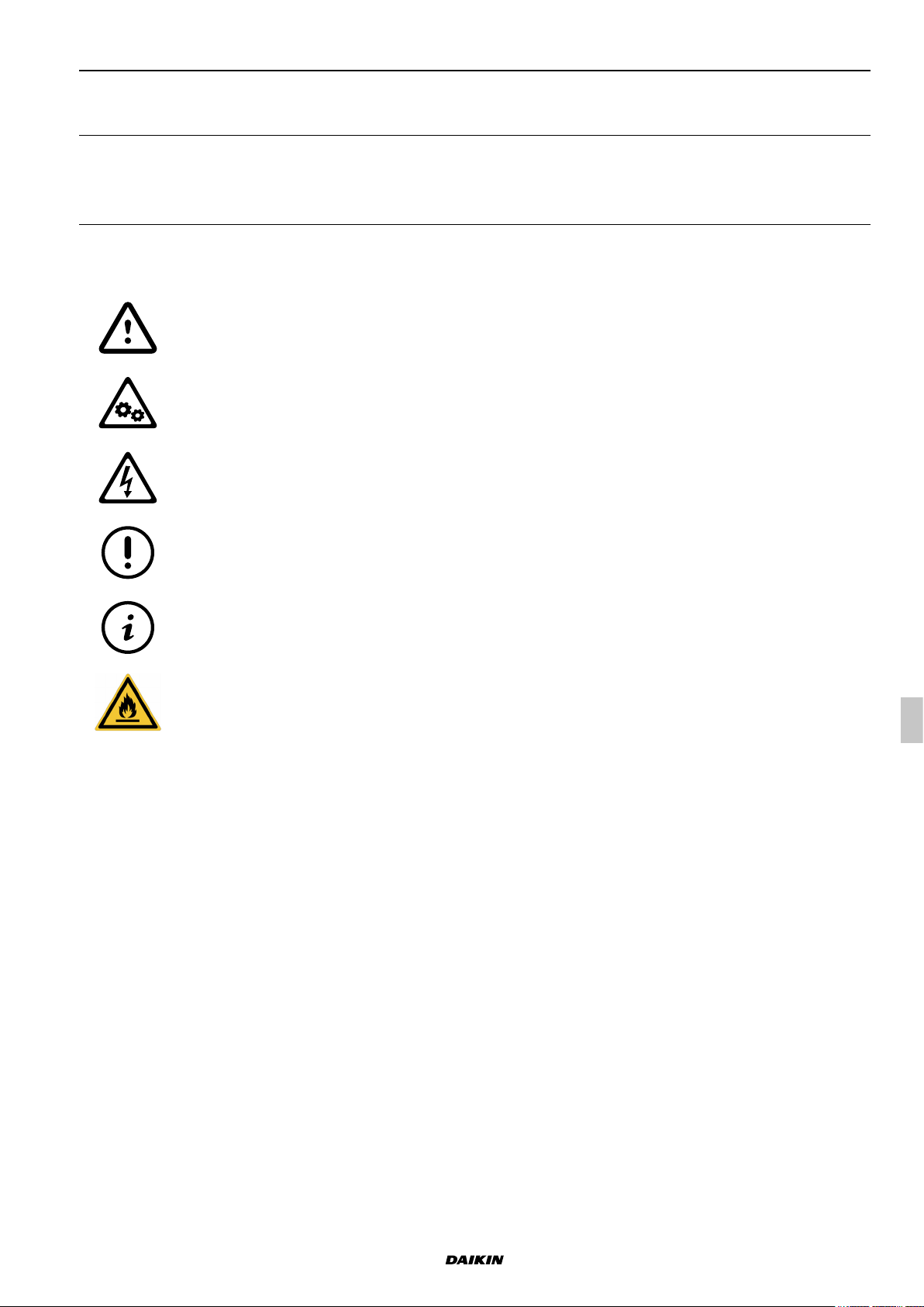
A description of the main symbols used in this manual and on the labels axed to the unit is given below.
Danger symbol; take extreme care.
Danger symbol; moving mechanical parts.
Danger symbol; live parts.
Warning symbol; important information
Note symbol; suggestions and advice
Danger sign: ammable gas.
We reserve the right to make changes without any prior notice.
UAT YA
4P645202-1
Translation from original instructions
Packaged Rooftop
7
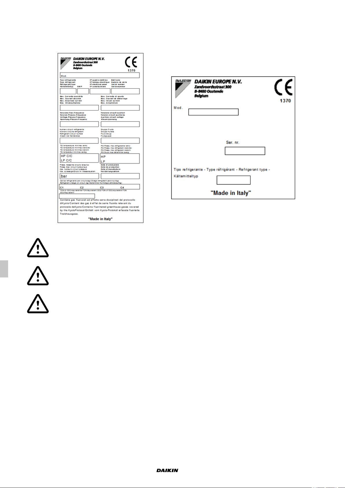
1.2.2 Labels
For the constructional features, available models and technical data, please refer to the Technical Catalogue.
The model, serial number, features, power supply voltage and so on are shown on the labels axed to the unit (the
following illustrations are shown only as an example).
The Manufacturer adopts a continuous development policy and, in this perspective, reserves the right
to make changes and improvements to the documentation and to the units without prior notice.
The Technical Catalogue, the labels placed directly on the unit and the various diagrams referred to
below, must be considered an integral part of this manual.
Do not remove or alter the labels placed on the unit.
Translation from original instructions
Packaged Rooftop
8
We reserve the right to make changes without any prior notice.
UAT YA
4P645202-1
2 SAFETY
2.1 General safety precautions
Access to the area around the unit must be prevented by special guarding where this is positioned in a location that
is not protected and can be reached by unqualied persons.
The equipment operator is responsible for complying with regulatory obligations.
The equipment operator is the person who has actual control over the technical operation and free access, which
means the possibility of monitoring its components and their operation and the possibility of granting access to third
parties.
The equipment operator has the power to decide on technical modications, checks and repairs.
The equipment operator may give instructions to employees or to external companies for carrying out maintenance
and repair operations.
Access to the unit must be granted exclusively to technicians authorised by the equipment operator.
The equipment must be installed and maintained or repaired by sta and contractors who hold a relevant certicate
issued by a certication body. Within Europe, the certication body must be designated by a member state to certify
compliance with the requirements laid down in Regulation (EU) No 517/2014 of the European Parliament and of the
Council of 16 April 2014 on uorinated greenhouse gases and repealing Regulation (EC) No 842/2006 Text with EEA
relevance.
Any operator gaining access to the unit must be authorised and qualied as specied by Annex HH of IEC 60335-2-
40:2018, by local legislations and, with respect to europen standards, by EN 378-4 and EN 13133 ", additionally, they
must have proper knowledge to perform all the activities required throughout the service life of the machine.
Access to the unit requires that the closing panels, where tted, are removed.
On no account must unqualied personnel be allowed to enter the unit and no one should be allowed to enter before
the power to it has been turned o.
The user can interact with the unit only through the control and external OK signals.
Only authorised knowledgeable personnel may access the unit in compliance with safety in the workplace regulations.
At European level, refer to Council Directive 89/391/EEC of 12 June 1989 on the introduction of measures to
encourage improvements in the health and safety of workers at work.
Also, knowledge and understanding of the manual are indispensable for reducing risks and for improving the health
and safety of workers.
The operator must know what to do when faced with possible anomalies, malfunctions or conditions of danger to
himself or others, and in any case, he must comply with the following instructions:
Stop the unit immediately by using the emergency device.
Do not do anything that goes beyond your duties and technical knowledge.
Inform the manager immediately and do not take personal initiatives.
Before carrying out any work on the unit, make sure you have turned o the power supply to it. Refer
to the section on maintenance work.
Before work is started on the unit: check for potentially ammable atmospheres; Make sure there are
no possible ignition sources comply with the requirements specied by Annex HH of standard IEC
60335-2-40:2018, by local legislations, and, with respect to europen standards, by EN 378-4 and EN
13133", and by existing local regulations.
We reserve the right to make changes without any prior notice.
UAT YA
4P645202-1
Translation from original instructions
Packaged Rooftop
9

In units with capacitors and/or inverters, certain components can remain live for several minutes even
after having turned o the main switch.
Wait 10 minutes before working on the electrical parts of the unit.
Circuits supplied from external sources (made with orange cable) can remain live even after the power
supply to the unit has been turned o.
Work on the unit only if there is sucient lighting for the type of work to be carried out.
Failure to comply with the instructions in this manual and any modications made to the unit without prior written
consent, will immediately void the warranty.
The law regulating the use of stratospheric ozone depleting substances prohibits the release of
refrigerant gases into the environment and obliges owners to recover and return them to the dealer or
take them to special collection centres at the end of their operational life.
The refrigerant contained in the refrigerant circuit is included among the substances subject to special
control regulations provided for by law and must therefore be disposed of as indicated above.
Particular care should be taken during maintenance operations in order to reduce refrigerant leaks as
much as possible.
2.1.1 Discharge of the safety valves
If present on the refrigerant circuit, installation requirements and/or national regulations lay down that the discharge
of the safety valves must be routed to the outside.
The conveying must be done with a pipe whose diameter must be at least that of the valve outlet, and the weight of
the pipe must not be borne by the valve.
Always direct the discharge to areas where the jet cannot cause harm to anyone.
Risk of burns following contact with hot and cold parts.
any material exhausted from the safety valves must be conveyed using pipes in compliance with
the national and/or European directives: the exhaust point must not be close to trap-doors, manhole
covers and any other opening where refrigerant may be contained; exhausted material must not
be conveyed close to fresh air inlets, doors or similar openings; exhausted material must not be
conveyed close to ignition sources, as dened in standard EN378-2.
It is responsibility of the installer to carry out a ammability risk assessment and a classication
of the danger zone at the site of installation, as required by standard EN378-3 and/or the national
regulations in place.
2.1.2 Emergency stop
In case of emergency, an immediate stop is carried out using the red disconnecting switch/master switch on the
electrical control panel by turning it to 0. When it is turned to 0, the disconnecting switch turns o the power to the
whole unit.
The main disconnect switch/master switch, used to electrically isolate the unit, is also intended for use
as an emergency device and it is only in an emergency that it should be used to stop the unit.
Except the case of an emergency stop, the unit must be stopped using its control software.
Translation from original instructions
Packaged Rooftop
10
We reserve the right to make changes without any prior notice.
UAT YA
4P645202-1
2.2 Basic rules
All the units are designed and built in compliance with Directive 2014/68/EU of the European Parliament and of the
Council of 15 May 2014 on the approximation of the laws of the Member States relating to pressure equipment.
To ensure maximum safety, in order to prevent possible risks, follow the instructions below:
- this product contains pressurised vessels, live components, moving mechanical parts and very hot and cold
surfaces that, in certain situations, can pose a risk: all maintenance work must be carried out by skilled personnel
equipped with the necessary qualications in accordance with current regulations. Before carrying out any
operation, make sure that the personnel in charge has full knowledge of the documentation supplied with the unit.
- always have a copy of the documentation near the unit.
- The operations indicated in this manual must be integrated with the procedures indicated in the user instruction
manuals of the other systems and devices incorporated in the unit. The manuals contain all the necessary
information for safely managing the devices and the possible operating modes.
- use suitable protection (gloves, hard hat, protective glasses, safety shoes, etc.) for all maintenance or control
operations carried out on the unit.
- Do not wear loose clothing, ties, chains, watches, etc., which can get caught in the moving parts of the unit.
- always use tools and protective equipment in excellent condition.
- The compressors and delivery gas pipes are at high temperature. Therefore, when working in the immediate
vicinity, be careful to avoid touching any components of the unit without suitable protection.
- do not work in the discharge trajectory of the safety valves.
- if the units are positioned in unprotected places which can easily be reached by unqualied persons, suitable
protection devices must be installed.
- the user must consult the installation and use system manuals, incorporated and attached to this manual.
- there may be potential risks that are not obvious. Warnings and signals are therefore displayed on the unit.
- Do not remove the warnings.
It is expressly forbidden to:
- remove or disable the safety guards;
- tamper with and/or modify, even partially, the safety devices installed on the unit.
If there are alarm warnings and consequent tripping of the safety devices, the user must call in skilled maintenance
technicians to x the problem immediately.
An accident can lead to serious injury or death.
The safety devices must be tested according to the guidelines in this manual.
The manufacturer does not assume any liability for damage/injury to persons, pets or objects arising from the re-use
of individual parts of the unit for functions or assembly situations dierent from the original ones. Tampering with/
unauthorised replacement of one or more parts of the unit is prohibited.
The use of accessories, tools or consumables other than those recommended by the Manufacturer relieves the latter
from civil and criminal liability.
Deactivation and scrapping of the unit must be carried out only by suitably trained and equipped personnel.
The units do not fall within the scope of Directive 2014/34/EU of the European Parliament and of
the Council, of 26 February 2014, on the approximation of the laws of the Member States relating to
equipment and protective systems intended for use in potentially explosive atmospheres.
Any operator gaining access to the unit must be authorised and qualied as specied by Annex HH
of IEC 60335-2-40:2018, by local legislations and, with respect to europen standards, by EN 378-4
and EN 13133 ", additionally, they must have proper knowledge to perform all the activities required
throughout the service life of the machine.
We reserve the right to make changes without any prior notice.
UAT YA
4P645202-1
Translation from original instructions
Packaged Rooftop
11
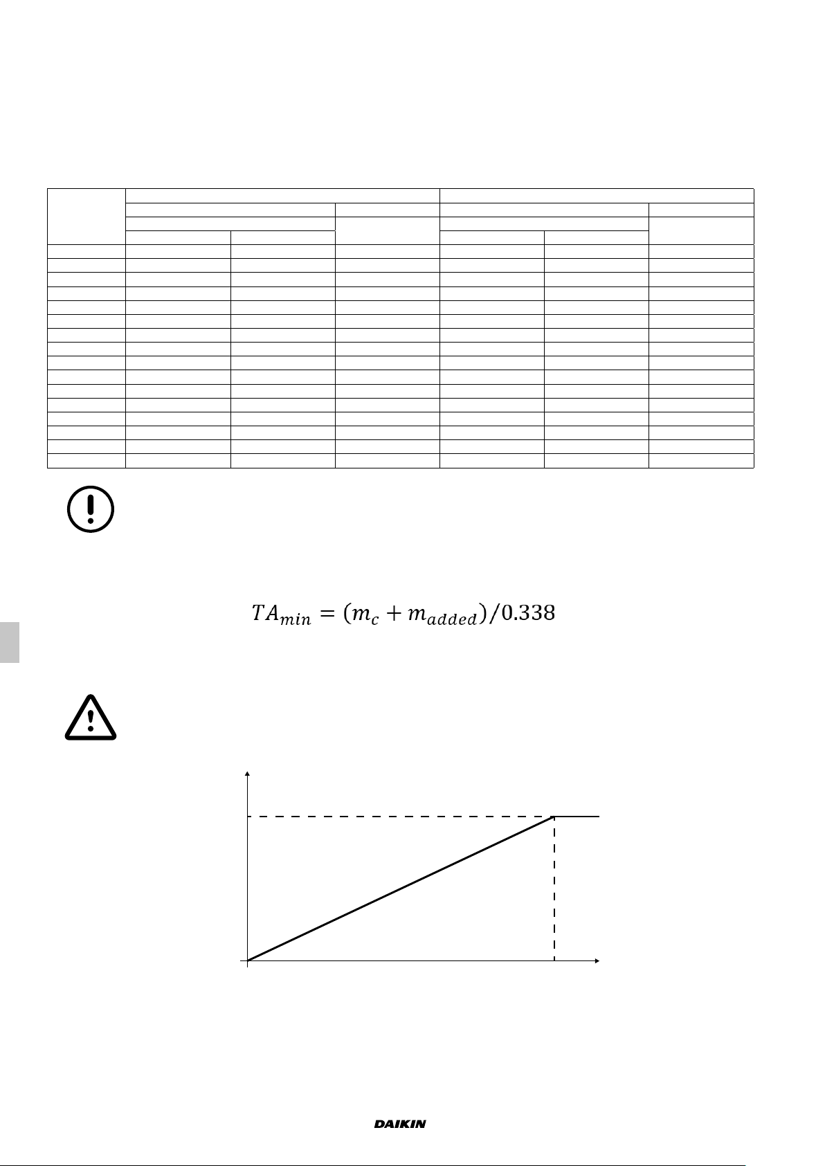
2.2.1 Limits to the use – Minimum area of the conditioned space and maximum
[m²]
m
[kg]
refrigerant charge
Clause GG.9 of Annex GG within the standard IEC 60335-2-40:2018 (Household and similar electrical appliances Safety - Part 2-40: Particular requirements for electrical heat pumps, air-conditioners and dehumidiers) denes the
charge limits based on the total conditioned space area and the ventilation requirements for ducted appliances using
A2L refrigerants. For full details refer to the standard IEC 60335-2-40:2018.
The minimum total conditioned room area "TA
accordance with following:
For units without hot gas post heating coil For units with hot gas post heating coil
m
Unit
Circuit 1 Circuit 2 Circuit 1 Circuit 2
UATYA25 7 - 20,7 8,3 - 24,4
UATYA30 10 - 29,6 11,3 - 33,5
UATYA40 12 - 35,5 13,7 - 40,6
UATYA50 15 - 44,4 17 - 50,4
UATYA60 18 - 53,3 21 - 62
UATYA70 18 - 53,3 21 - 62
UATYA80 23 - 68,1 26,9 - 79,6
UATYA90 24 - 71,1 28 - 83
UATYA100 28 - 82,9 32,3 - 95,7
UATYA110 30 - 88,8 34,7 - 102,8
UATYA120 36 - 106,6 41,2 - 122,1
UATYA140 19 19 56,3 23,1 23,1 68,4
UATYA150 19 19 56,3 23,1 23,1 68,4
UATYA160 23 23 68,1 27,9 27,9 82,6
UATYA180 25 25 74 25 25 74
UATYA190 25 25 74 25 25 74
[kg]
c
" of installed appliance with refrigerant charge "mc" (kg) shall be in
min
TA
min
2
m
m
[kg]
c
TA
min
2
m
No zoning dampers shall be installed in the rooms considered to determine the minimum room area
unless these zoning dampers can be fully opened by the control signal of the rooftop in case of a leak
If the refrigerant charge is adjusted on the eld, the minimum area must be re-evaluated in order to be always above
the result obtained through the following formula:
where
- m
is the refrigerant charge added on the eld in kg.
added
The sum “mc+m
" must be lower than 79,8 kg for each circuit.
added
The minimum area according to the area of the conditioned space is shown below
90
80
70
c
60
50
40
30
20
10
0
50
100 150 200 2500
Translation from original instructions
Packaged Rooftop
12
Fig. 1 Total min. installation area
We reserve the right to make changes without any prior notice.
UAT YA
4P645202-1
The unit is equipped with a refrigerant detection system that complies with Annex LL of the IEC 60335-2-40:2018,
which position has been checked according to test reported in Annex MM of IEC 60335-2-40:2018.
When the refrigerant detection system detects a leak, the following will be initiated by the unit:
• disable the compressor operation unless the compressors;
• Supply and return (if present) fan control will be set to to constant airow logic with a x airow value. The fans
will operate continuously even if time tables are set. This in order to not let the airow to go below "Q
" (see
min
below);
• Energize a dedicated relay in the electrical cabinet in order to fully open any external zoning dampers;
• Set the dampers (if installed on the appliance) in order to have a full intake of fresh air and a full expulsion of the
return air.
External zoning dampers, if present, must be connected to this relay in order to be open when a leak
is detected
Zoning dampers installed in rooms considered to determine the minimum room area must be
electrically powered at all times after installation, other than when servicing, to be eective for safety.
The refrigerant detection system and controls will maintain the above action until at least 5 min after the refrigerant
detection system has reset. Building re and smoke systems may override this function.
If the leak detector detects a leak, the above operations will be initiated even if the unit is turned OFF
by button, by BMS or by digital input.
In addition to what above another dedicated relay is present in the unit electrical cabinet and
connected directly to the leak detector alarm. This relay can be used to monitor the leak detector
alarm even in case of a unit control board fault.
The minimum circulation airow (Q
) circulated to the total conditioned space, expressed in m3⁄h, must be in
min
accordance with the following table:
For units without hot gas post heating coil For units with hot gas post heating coil
Unit
UATYA25 7 - 1368 8,3 - 1613
UATYA30 10 - 1954 11,3 - 2208
UATYA40 12 - 2345 13,7 - 2680
UATYA50 15 - 2932 17 - 3326
UATYA60 18 - 3518 21 - 4095
UATYA70 18 - 3518 21 - 4095
UATYA80 23 - 4495 26,9 - 5255
UATYA90 24 - 4691 28 - 5479
UATYA100 28 - 5472 32,3 - 6315
UATYA110 30 - 5863 34,7 - 6783
UATYA120 36 - 7036 41,2 - 8059
UATYA140 19 19 3713 23,1 23,1 4515
UATYA150 19 19 3713 23,1 23,1 4515
UATYA160 23 23 4495 27,9 27,9 5453
UATYA180 25 25 4886 25 25 4886
UATYA190 25 25 4886 25 25 4886
m
c
[kg] m3/h [kg] m3/h
Q
min
m
c
Whenever the ow, measured by the dierantial air presssure tranducer, falls below the values
reported in the table above, the airow alarm from dierential pressure transducer will be displayed on
the unit control and the unit will be stopped.
Q
min
The supply and return air shall be directly ducted to the conditioned space. Open areas such as false ceilings shall
not be used as a return air duct.
We reserve the right to make changes without any prior notice.
UAT YA
4P645202-1
Translation from original instructions
Packaged Rooftop
13
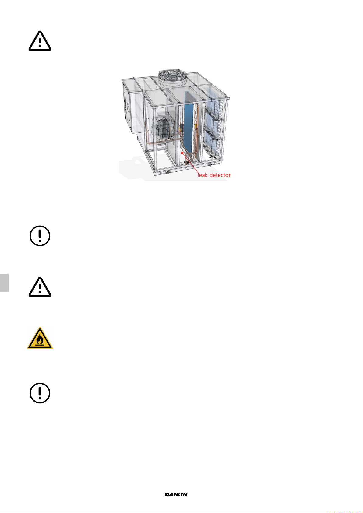
2.2.2 Refrigerant leak detector
This unit is equipped with a refrigerant leak detector for safety.
To be eective, the unit must be electrically powered at all times after installation, other than when
servicing.
A refrigerant leak detector is installed in the unit between the supply coil and the supply fan(s).
This device allows immediate detection of refrigerant leaks in order to start what reported in the above paragraph
“Limit to the use – This device allows immediate detection of refrigerant leaks in order to start what reported in the
above paragraph “Limit to the use – Minimum area required and maximum refrigerant charge”.
The detector has an internal self-testing routine. If this routine detects a fault the unit control will
automatically modify the supply and return (if present) fan control in order to set a constant airow
logic with a x airow value. This in order to not let the airow to go below Q
as dened in the
min
paragraph "Limit to the use – Minimum area required and maximum refrigerant charge”. The fans will
operate continuously even if time tables are set, in order to have always the minimum required airow.
In the unlike event that the airow is not able to reach the minimum airow level "Q
and the leak
min
detector is faulty, a dedicated relay in the electrical cabinet will be energized. This signal must be
used to warn the user that the airow is reduced (e.g. a buzzer and a ashing light).
Once the gas alarm of the leak detector system is released, the output is not reset even if the gas
concentration decreases. After detecting and repairing the leak spot, a manual reset of the alarm
can be operated. To reset the alarm output turn the power supply to the gas sensor o and on (e.g.
disconnecting and reconnecting its cable), if the alarm output will not be reset after this operation, it
means that leak has exceeded 10000 ppm, and the gas sensor has to be replaced.
The gas sensing part of the sensor has a designed life of 10 years. A countdown is set inside the
detector control and read by the unit control.
Six months before the expire of the countdown a warning message will appear on the unit HMI. If the
calibration will not be performed in time a warning message will appear on the unit HMI and the unit
control will operate as in case of a leak detector fault (see rst informative point of this paragraph).
Translation from original instructions
Packaged Rooftop
14
We reserve the right to make changes without any prior notice.
UAT YA
4P645202-1
2.2.3 Water ow rate at the heat exchangers
It is necessary to ensure that the water ow rate during operation is no higher than 1.5 times and no lower than 0.5
times the nominal ow rate of the unit stated in the Technical Catalogue.
In any case, refer to the specic Technical Catalogue for the allowed conditions for water ow in and
out of the exchangers.
2.2.4 Water composition
Dissolved substances in the water can cause corrosion in the heat exchangers.
It is mandatory to make sure the parameters of the water comply with the following table:
Description Values
Total hardness 2,0 ÷ 6,0 °f
Langelier index - 0,4 ÷ 0,4
pH 7,5 ÷ 8,5
Electrical conductivity 10÷500 µS/cm
Organic elements -
Hydrogen carbonate (HCO3-) 70 ÷ 300 ppm
Sulphates (SO42-) < 50 ppm
Hydrogen carbonate / Sulphates (HCO3-/SO42-) > 1
Chlorides (Cl-) < 50 ppm
Nitrates (NO3-) < 50 ppm
Hydrogen sulphide (H2S) < 0,05 ppm
Ammonia (NH3) < 0,05 ppm
Sulphites (SO3), free chlorine (Cl2) < 1 ppm
Carbon dioxide (CO2) < 5 ppm
Metal cations < 0,2 ppm
Manganese ions (Mn++) < 0,2 ppm
Iron ions (Fe2+, Fe3+) < 0,2 ppm
Iron + Manganese < 0,4 ppm
Phosphates (PO43-) < 2 ppm
Oxygen < 0,1 ppm
ppm = mg/l
The use of water with values above the limits stated in the table will immediately void the warranty.
It is mandatory to include a system for eliminating possible organic substances in the water that could pass through
the lter and settle in the heat exchangers, which would lead to malfunctioning and/or breakage over time.
The use of water containing organic substances will immediately void the warranty.
We reserve the right to make changes without any prior notice.
UAT YA
4P645202-1
Translation from original instructions
Packaged Rooftop
15
2.2.5 Warnings concerning ammable refrigerants
Units with mildly ammable refrigerants (A2L), such as R32, shall be installed in accordance with the
European standards and regulations and with the local regulations, where applicable.
The information below is provided in accordance with standard IEC 60335-2-40:2018 and its annexes
and clauses (here in after “Annex” and “Clause”) and it has been taken from the English version of the
standard, which is the document to be referenced.
(Annex DD.2) Do not use means to accelerate the defrosting process or to clean, other than those
recommended by the manufacturer.
The external unit shall be stored in a room without continuously operating ignition sources (for
example: open ames, an operating gas appliance or an operating electric heater).
Do not pierce or burn.
Be aware that refrigerants may not contain an odour.
(Annex DD.3.3) Qualication of workers
Any operation concerning the installation, maintenance, repair, disassembly and dismantling of the unit shall be
carried out by qualied personnel, in accordance with Annex HH to standard IEC 60335-2-40:2018, who hold a valid
certicate in compliance with the existing standards.
The above-mentioned operations include:
• breaking into the refrigerating circuit;
• opening of sealed components;
• opening of ventilated enclosures.
(Annex DD.4) Information on servicing
(Annex DD.4.2) Checks to the area
Prior to beginning work on systems containing ammable refrigerants, safety checks in the area are necessary
to ensure that the risk of ignition is minimised. For repair to the refrigerating system, DD.4.3 to DD.4.7 shall be
completed prior to conducting work on the system.
Translation from original instructions
Packaged Rooftop
16
We reserve the right to make changes without any prior notice.
UAT YA
4P645202-1
Prior to beginning work on systems containing ammable refrigerants, safety checks in the area are necessary
to ensure that the risk of ignition is minimised. For repair to the refrigerating system, DD.4.3 to DD.4.7 shall be
completed prior to conducting work on the system.
(Annex DD.4.3) Work procedure
Work shall be undertaken under a controlled procedure so as to minimise the risk of a ammable gas or vapour being
present while the work is being performed.
(Annex DD.4.4) General work area
All maintenance sta and others working in the local area shall be instructed on the nature of the work being carried
out. Work in conned spaces shall be avoided.
(Annex DD.4.5) Checking for presence of refrigerant
The area shall be checked with an appropriate refrigerant detector prior to and during work, to ensure the technician
is aware of potentially toxic and ammable atmospheres.
Ensure that the refrigerant or leak detection equipment being used is suitable for use with the refrigerant applicable
to the unit, i.e. non-sparking, adequately sealed or intrinsically safe.
(Annex DD.4.6) Presence of re extinguisher
If any hot work is to be conducted on the unit requiring an increase in the temperature of parts of the unit (e.g. brazing),
appropriate re extinguishing equipment shall be available to hand. Have a dry powder or CO2 re extinguisher
adjacent to the refrigerant charging area.
(Annex DD.4.7) No ignition sources
No person carrying out work in relation to a unit shall use any sources of ignition in such a manner that it may lead to
the risk of re or explosion. All possible ignition sources, including cigarette smoking, should be kept suciently far
away from the site of installation, repairing, removing and disposal of the unit, during which ammable refrigerant can
possibly be released to the surrounding space. Prior to work taking place, the area around the unit is to be surveyed
to make sure that there are no ammable hazards or ignition risks. “No Smoking” signs shall be displayed.
We reserve the right to make changes without any prior notice.
UAT YA
4P645202-1
Translation from original instructions
Packaged Rooftop
17
 Loading...