

Daikin DPS, MPS, RAH, RDT, RFS Installation And Maintenance Manual
...
Installation and Maintenance Manual IM 919-3
Group: Applied Air Systems
Part Number: IM 919
Date: October 2014
MicroTech® III Controller for Commercial Rooftop
Systems, Applied Rooftop Systems and Self-Contained
Air Conditioners
Models: DPS, MPS, RAH, RCS, RDS, RDT, RFS, RPE, SWP and SWT

Table of ConTenTs
Introduction .................................3
General Description ..........................3
Component Data ............................3
Main Control Board (MCB) ...................4
Keypad/Display ..............................5
Passwords .................................6
Navigation Mode ............................6
Edit Mode ..................................6
Remote Keypad Display Option .................6
About this AHU ..............................6
Controller Application Software
Upgrade Procedures ..........................7
Description of Operation ......................8
Temperature Sensors .........................8
Pressure Sensors ...........................9
Troubleshooting Pressure Transducers .........9
Duct Pressure Sensor ......................10
Building Pressure Sensor ...................11
Mamac Panel-Mounted Pressure Transducer ....12
Actuators ................................13
Variable Frequency Drives (VFD’s) ............13
Smoke Detectors .........................13
ECM (Electronically Commutated Motor)
fan/motor ................................13
Controller Inputs/Outputs .....................14
Table of ConTenTs
Field Wiring ................................24
Field Output Signals .......................24
Field Analog Input Signals ..................25
Field Digital Input Signals ...................28
Emergency Shutdown ......................29
OA Damper Flow Station with CO2 Reset Setup ..29
CO2 Sensor wiring .........................29
EBTRON or Field OA Flow Station Wiring.......30
Cooling: Multistage ..........................31
Compressor Staging ........................31
Communication Module ......................40
Network Communications ....................40
Unit Conguration Setup Menu ................41
Typical Electrical Drawings - RoofPak ..........44
Typical Electrical Drawings - Maverick...........59
Typical Electrical Drawings - Rebel .............64
Typical Electrical Drawings - Self-Contained .....75
Parts List ...................................81
IM 919-3 • MICROTECH III CONTROLLER 2 www.DaikinApplied.com
InTroduCTIon
This manual contains information regarding the MicroTech® III
control system used in the Daikin Rooftop and Self Contained
product lines. It describes the MicroTech III components, input/
output congurations, eld wiring options and requirements,
and service procedures. For a description of operation and
information on using the keypad to view data and set control
parameters, refer to the appropriate operation manual. For
installation and commissioning instructions and general
information on a particular unit model, refer to its model-
specic installation manual.
Table 1: Operation, Installation and Maintenance Resources
Unit Manual
MicroTech III Rooftop Unit Controller -
BACnet IP Communications
MicroTech III Rooftop Unit Controller
-BACnet MSTP Communications
MicroTech III Rooftop Unit Controller
-BACnet LON Communications
Rooftop/Self-Contained Operation OM 920
MicroTech III Remote Unit Interface IM 1005
RPS/RDT/RFS/RCS 015C-105C IM 926
RPS/RDT/RFS/RCS 015D-140D IM 893
SWP Self-Contained (012H-130H) IM 1032
RoofPak RAH/RDS IM 987
Maverick II Rooftop 62-75 ton IM 991
Maverick II Rooftop 15-50 ton IM 1058
IM 916
IM 917
IM 918
InTroduCTIon
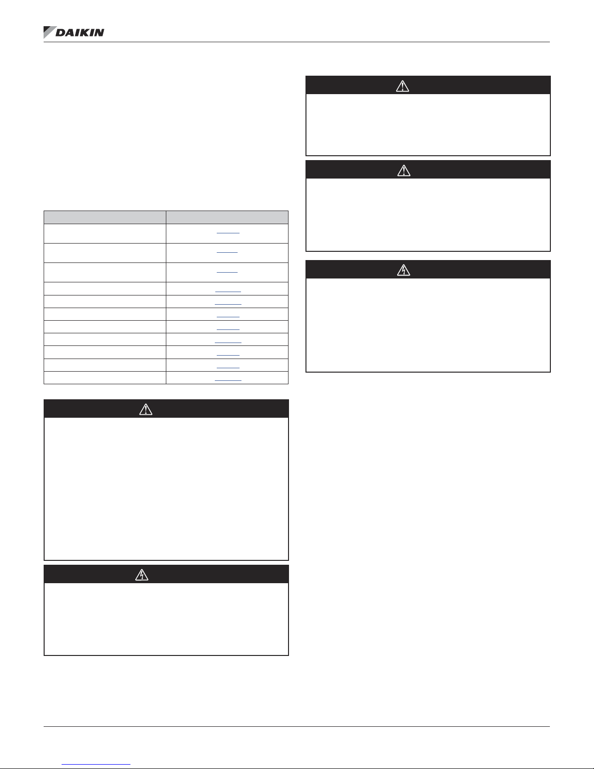
WARNING
Excessive moisture in the control panel can cause hazardous
working conditions and improper equipment operation.
When servicing this equipment during rainy weather, the
electrical components in the main control panel must be
protected from the rain..
CAUTION
Extreme temperature hazard. Can cause damage to system
components.
The MicroTech III controller is designed to operate in ambient
temperatures from -20°F to 125°F. It can be stored in ambient
temperatures from -40°F to 140°F. It is designed to be stored
and operated in relative humidity up to 95% (non-condensing).
WARNING
Static sensitive components. A static discharge while
handling electronic circuit boards can cause damage to the
components.
Discharge any static electrical charge by touching the bare
metal inside the main control panel before performing any
service work. Never unplug any cables, circuit board terminal
blocks, relay modules, or power plugs while power is applied
to the panel.
NOTICE
This equipment generates, uses, and can radiate radio
frequency energy and, if not installed and used in accordance
with this instruction manual, may cause interference to radio
communications. It has been tested and found to comply with
the limits for a Class A digital device, pursuant to part 15 of the
FCC rules. These limits are designed to provide reasonable
protection against harmful interference when the equipment
is operated in a commercial environment. Operation of this
equipment in a residential area is likely to cause harmful
interference in which case the user is required to correct
the interference at his own expense. Daikin International
disclaims any liability resulting from any interference or for the
correction thereof.
WARNING
Electric shock hazard. Can cause personal injury or equipment
damage.
This equipment must be properly grounded. Connections and
service to the MicroTech III control panel must be performed
only by personnel that are knowledgeable in the operation of
the equipment being controlled.
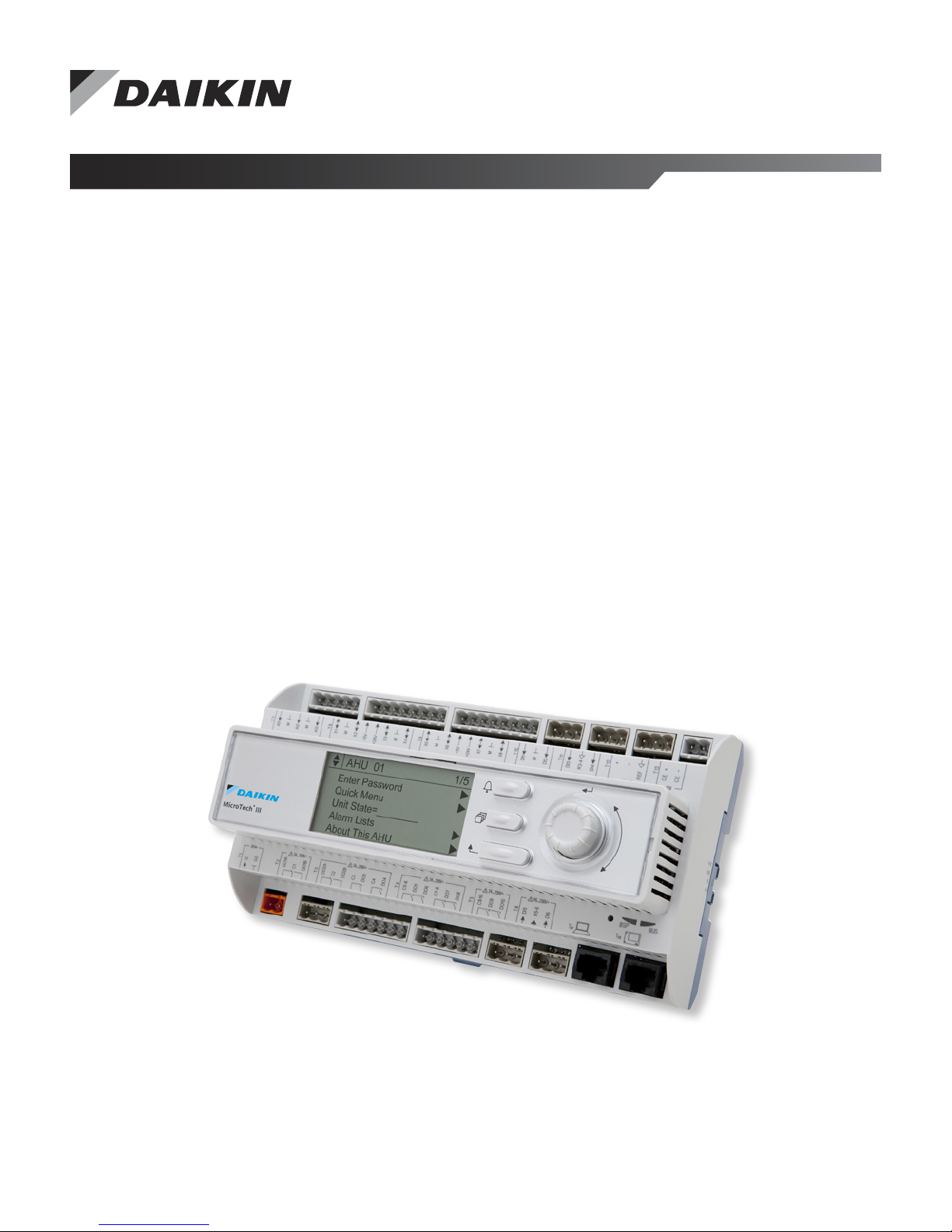
General Description
The MicroTech III Unit Controller is a microprocessor-based
controller designed to provide sophisticated control of Daikin
Air Handling unit. In addition to providing normal temperature,
static pressure, and ventilation control, the controller can
provide alarm monitoring and alarm-specic component
shutdown if critical system conditions occur.
The operator can access temperatures, pressures, operating
states, alarm messages, control parameters, and schedules
with the keypad/display. The controller includes password
protection against unauthorized or accidental control parameter
changes.
This MicroTech III controller is capable of complete, standalone rooftop unit control, or it can be incorporated into a
building-wide network using an optional plug-in communication
module. Available communication modules include BACnet/IP,
BACnet® MS/TP, and LonMark®.
Component Data
The main components of the MicroTech III control system
include the main control board (MCB) with a built in keypad/
display and I/O’s, Expansion Modules A, B, C, D, E.
Transformers T2, T3 and T9 supply power to the system. The
following pages contain descriptions of these components and
their input and output devices.
www.DaikinApplied.com 3 IM 919-3 • MICROTECH III CONTROLLER
InTroduCTIon
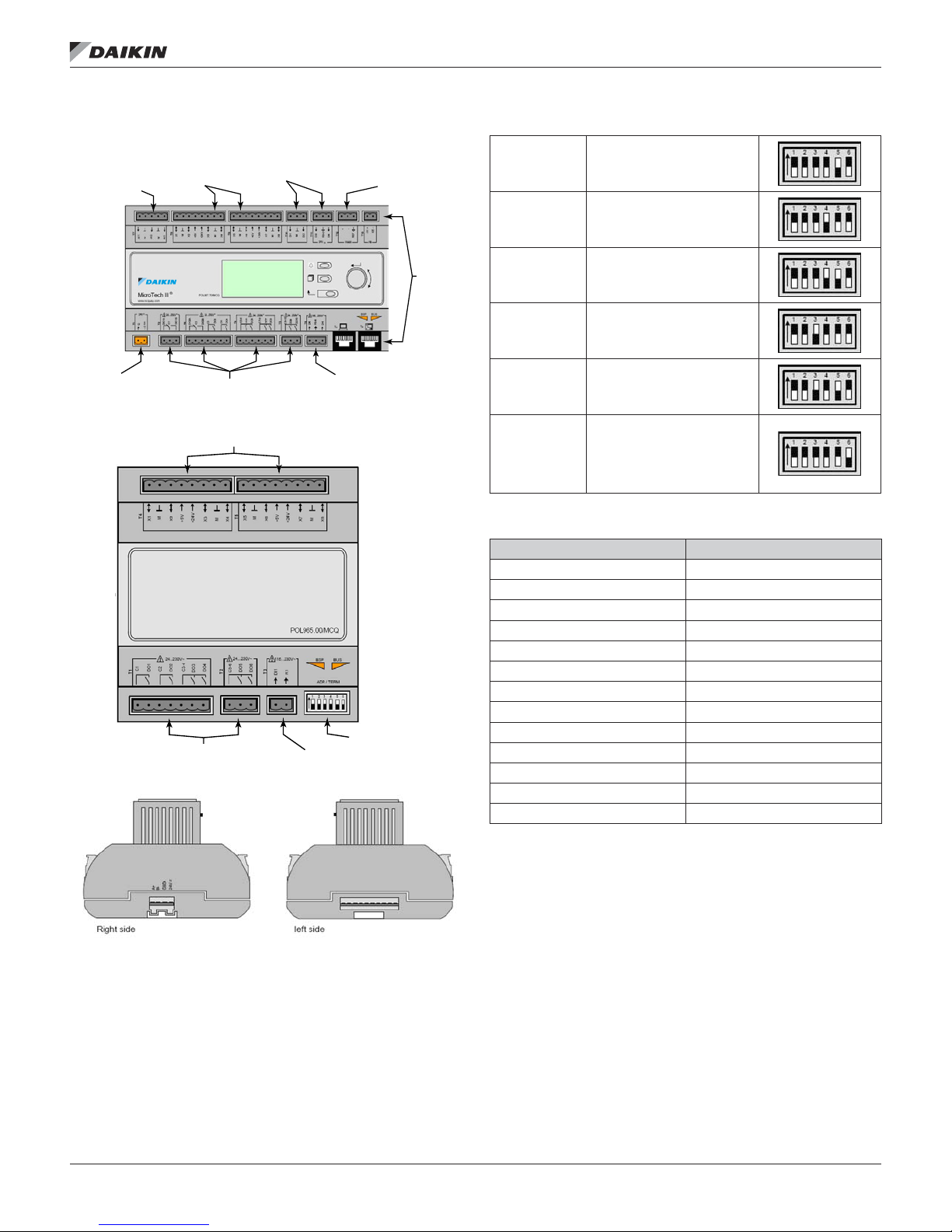
Main Control Board (MCB)
Figure 1: Main Control Board
Analog Inputs
Power
Supply
Universal I/O
Figure 2: Expansion Boards A, B, C, D, E
Digital Output
Figure 3: Expansion Board Side Views
Digital Inputs
Digital Outputs
Universal I/O
Digital Inputs
Digital Input
Internal Modbus
Dip Switches
Remote
Keypad/
Display
Figure 4: Dip Switch Settings
Expansion
Board A
Expansion
Board B
Expansion
Board C
Expansion
Board D
Expansion
Board E
Switch #5 in the up
position (all others down)
Switch #4 in the up
position (all others down)
Switch #4 and #5 in the
up position (all others
down)
Switch #3 in the up
position (all others down)
Switch #3 and #5 in the
up position (all others
down)
Switch #6 must be in the
up position on the last
Dipswitch #6
expansion board in the
string regardless whether
it is A, B, C, D, or E.
Table 2: MCB I/O Connection Labeling
MCB I/O Connection Label
T1 24 VOLT POWER SUPPLY
T2 DIGITAL OUTPUT 1,
T3 DIGITAL OUTPUT 2, 3, 4
T4 DIGITAL OUTPUT 5, 6, 7, 8
T5 DIGITAL OUTPUT 9, 10
T6 DIGITAL INPUT 5, 6
T7 ANALOG INPUT 1, 2, 3
T8 UNIVERSAL I/O 1, 2, 3, 4
T9 UNIVERSAL I/O 5, 6, 7, 8
T10 DIGITAL INPUT 1, 2
T11 DIGITAL INPUT 3, 4
T12 MODBUS/VFD
T13 PROCESS BUS/FUTURE
IM 919-3 • MICROTECH III CONTROLLER 4 www.DaikinApplied.com
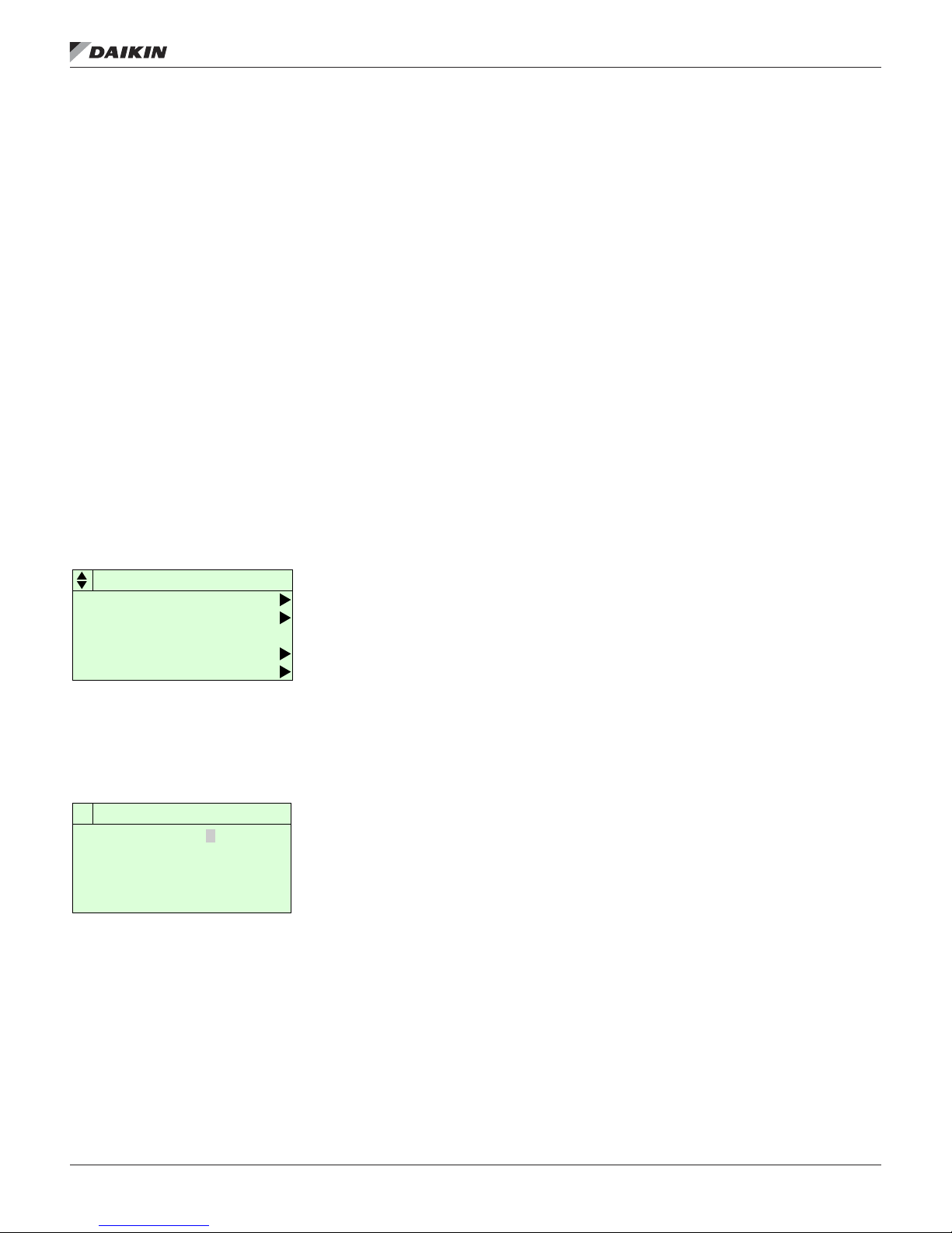
Keypad/dIsplay
The keypad/display consists of a 5-line by 22 character display,
three keys and a “push and roll” navigation wheel. There is an
Alarm Button, Menu (Home) Button, and a Back Button. The
wheel is used to navigate between lines on a screen (page)
and to increase and decrease changeable values when editing.
Pushing the wheel acts as an Enter Button.
Figure 5: Keypad/Display
The rst line on each page includes the page title and the line
number to which the cursor is currently “pointing”. The line
numbers are X/Y to indicate line number X of a total of Y lines
for that page. The left most position of the title line includes an
“up” arrow to indicate there are pages “above” the currently
displayed items, a “down” arrow to indicate there are pages
“below” the currently displayed items or an “up/down” arrow
to indicate there are pages “above and below” the currently
displayed page.
Each line on a page can contain status only information or
include changeable data elds. When a line contains status
only information and the cursor is on that line all but the value
eld of that line is highlighted meaning the text is white with
a black box around it. When the line contains a changeable
value and the cursor is at that line, the entire line is highlighted.
Each line on a page may also be dened as a “jump” line,
meaning pushing the navigation wheel will cause a “jump” to
a new page. An arrow is displayed to the far right of the line to
indicate it is a “jump” line and the entire line is highlighted when
the cursor is on that line.
The keypad/display Information is organized into Menu groups;
Main Menu, Quick Menu, View/Set Unit Menu, Commission
Unit Menu, Manual Control Menu, Service Menu, Unit
Conguration Menu and Alarm list Menus.
NOTE: Only menus and items that are applicable to the
specic unit conguration are displayed.
Keypad/dIsplay
The Main Menu allows the user to enter a password, access
the Quick Menu pages, view the current unit state, access the
Alarm List Menu as well as access to information about the
unit. The Quick Menu provides access to status information
indicating the current operating condition of the unit. The
View/Set Unit Menus include basic menus and items required
to setup the unit for general operation. These include such
things as control mode, occupancy mode, and heating and
cooling setpoints. The Commission Unit Menus include more
advanced items for “tuning” unit operation such as PI loop
parameters and time delays. The Manual Control Menu allows
service personnel to test unit specic operation manually.
The Unit Conguration Menu allows the user to access to the
unit specic conguration information. These generally do not
needing changing or accessing unless there is a fundamental
change to, or a problem with, the unit operation. The Alarm
Lists Menu includes active alarm and alarm log information.
www.DaikinApplied.com 5 IM 919-3 • MICROTECH III CONTROLLER
About This AHU
Keypad/dIsplay
Passwords
Various menu functions are accessible or inaccessible,
depending on the access level of the user, and the password
they enter, if any. There are four access levels, including no
password, Level 2, Level 4, and Level 6, with Level 2 having
the highest level of access. Without entering a password, the
user has access only to basic status menu items. Entering
the Level 6 password (5321) allows access to the Alarm Lists
Menu, Quick Menu, and the View/Set Unit Menus group.
Entering the Level 4 password (2526) allows similar access
as Level 6 with the addition of the Commission Unit Menu,
Manual Control, and Service Menu groups. Entering the Level
2 password (6363) allows similar access as Level 4 with the
addition of the Unit Conguration Menu.
NOTE: Alarms can be acknowledged without entering a
password.
The main password page is displayed when the keypad/display
is rst accessed, the Home Key is pressed, the Back Key is
pressed multiple times, or if the keypad/display has been idle
longer than the Password Timeout (default 10 minutes). The
main password page provides access to enter a password,
access the Quick Menu, view the current Unit State, access the
alarm lists or view information about the unit.
Figure 6: Password Main Page
AHU 01 1/5
Enter Password
Quick Menu
Unit State=________
Alarm Lists
The password eld initially has a value **** where each *
represents an adjustable eld. These values can be changed
by entering the Edit Mode described below.
Figure 7: Password Entry Page
Enter Password� 1/1
Enter Password
Entering an invalid password has the same effect as continuing
without entering a password. Once a valid password has been
entered, the controller allows further changes and access
without requiring the user to enter a password until either the
password timer expires or a different password is entered.
The default value for this password timer is 10 minutes. It is
changeable from 3 to 30 minutes via the Timer Settings menu.
** **
Navigation Mode
In the Navigation Mode, when a line on a page contains no
editable elds all but the value eld of that line is highlighted
meaning the text is white with a black box around it. When the
line contains an editable value eld the entire line is inverted
when the cursor is pointing to that line.
When the navigation wheel is turned clockwise, the cursor
moves to the next line (down) on the page. When the wheel is
turned counter-clockwise the cursor moves to the previous line
(up) on the page. The faster the wheel is turned the faster the
cursor moves.
When the Back Button is pressed the display reverts back to
the previously displayed page. If the Back button is repeatedly
pressed the display continues to revert one page back along
the current navigation path until the “main menu” is reached.
When the Menu (Home) Button is pressed the display reverts
to the “main page”.
When the Alarm Button is pressed, the Alarm Lists menu is
displayed.
Edit Mode
The Editing Mode is entered by pressing the navigation wheel
while the cursor is pointing to a line containing an editable eld.
Once in the edit mode pressing the wheel again causes the
editable eld to be highlighted. Turning the wheel clockwise
while the editable eld is highlighted causes the value to be
increased. Turning the wheel counter-clockwise while the
editable eld is highlighted causes the value to be decreased.
The faster the wheel is turned the faster the value is increased
or decreased. Pressing the wheel again cause the new value
to be saved and the keypad/display to leave the edit mode and
return to the navigation mode.
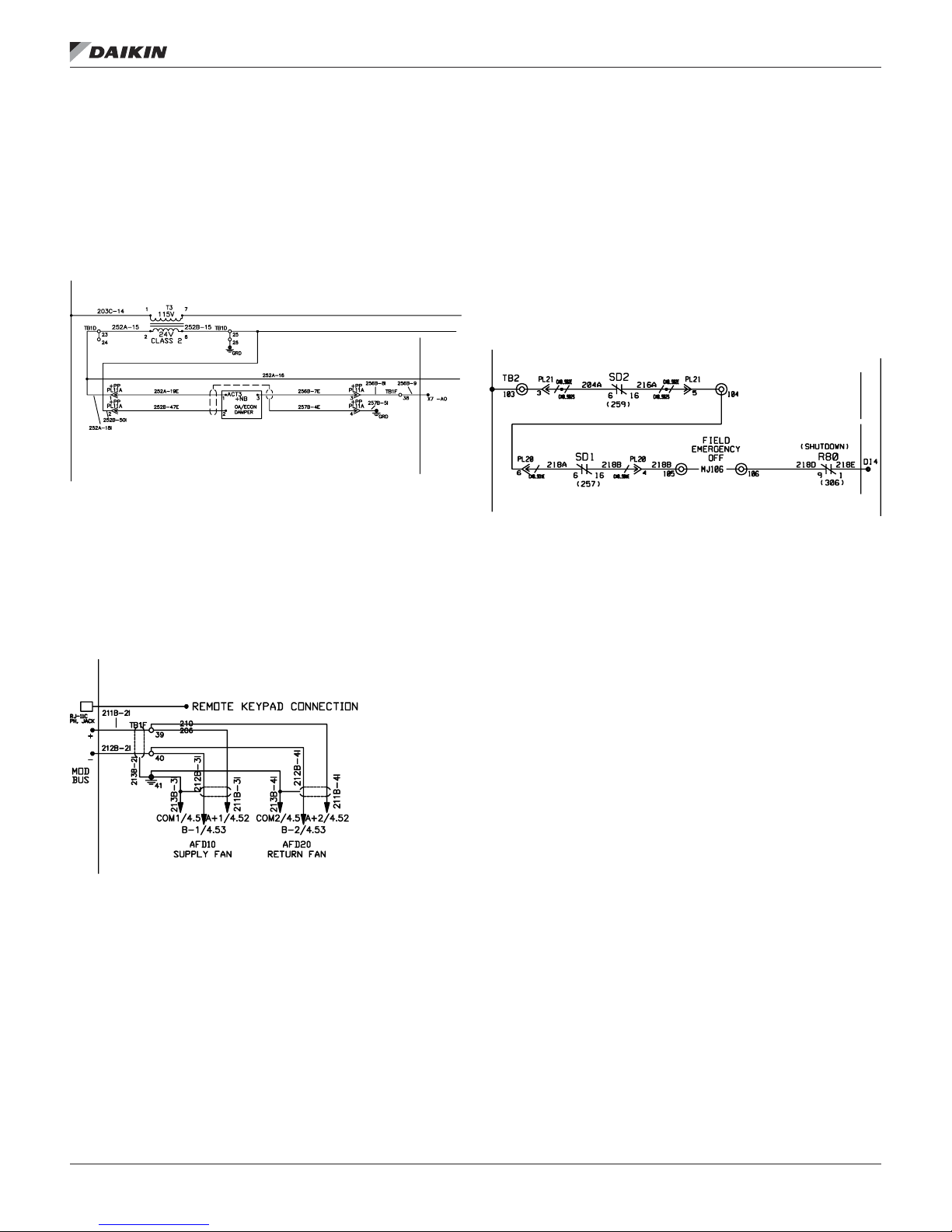
Remote Keypad Display Option
The remote user interface is designed for display, system
conguration, set-up and management of Daikin MicroTech III
applied air units.
In addition to the unit-mounted user interface provided with
MicroTech III controls, Daikin HVAC (applied rooftop systems,
indoor vertical self-contained systems, or commercial rooftop
systems) can be equipped with a remote user interface that
handles up to eight units per interface. The remote user
interface provides access to unit diagnostics and control
adjustments. The remote user interface provides the same
functionality as the unit-mounted controller.
About this AHU
The About this AHU menu item provides the user with
the current APP version (application code version), the
conguration code string for this unit, the BSP version
(rmware version) as well as the HMI/OBH GUID version
(software identiers). Each new release of application code
will have a unique set of software identiers. The information
shown in the HMI/OBH GUID version will list the information
needed to verify a match to the APP version.
IM 919-3 • MICROTECH III CONTROLLER 6 www.DaikinApplied.com

ConTroller applICaTIon sofTware upgrade proCedures
Use this procedure to upgrade the MicroTech III controller
application code software. To Load the les into the controller,
you will need an SD memory card no larger than 8GB with a
FAT32 le system format.
NOTE: If your existing BSP version is older than 8.40 or the
APP version is earlier than 2506017300 consult with
the Daikin Applied Technical Response Center (TRC)
for upgrade support.
NOTE: Attempting to install older rmware/software into the
controller than it currently has installed will prevent
the application code from operating. The controller
will have to be returned to TRC to restore operation.
1. The application and rmware les are compressed in
a ZIP archive le and MUST be extracted to the root
directory of the SD card. If your extraction program
automatically creates a le folder on the SD card the
contents of the le folder will need to be moved to the
root directory of the SD card.
2. Enter the 6363 password.
3. From the Main Menu, set the Control Mode to OFF.
4. Insert the SD memory card into the controller’s memory
card slot. The label on the SD card should be facing the
rear, toward the controller.
Figure 8: SD Memory Card Slot
Insert with
label to the
back
5. Save the existing conguration and parameters to the
memory card.
NOTE: If you do not want to Save & Restore, skip to Step
9 below.
6. From the Main Menu select Service Menus then Save/
Restore Settings.
7. Set the SaveToCard parameter to Yes, and press the
Enter button. When parameter reverts back to No Save
to Card is complete.
8. Power off the controller and wait 15 Seconds.
9. Make sure that all communication modules that need to
be updated are connected.
10. Insert a small tool such as a 3/64" (1mm) Hex key or
other similar tool in the service hole on the controller and
hold the service button depressed.
Figure 9: Service Button and BSP LED
ConTroller applICaTIon sofTware upgrade proCedures
Service Button
BSP LED
11. While holding the service button depressed apply power
to the controller.
12. Continue depressing the service button until the BSP LED
on the controller begins to ash between red and green.
13. Release the service button
14. When the BSP LED has stopped ashing between red
and green, remove power to the controller and wait 15
seconds.
15. Repeat steps 10-14. (Perform the uploading of code
procedure twice).
16. If you have a communication module to update you
will perform the procedure a third time. Make sure you
wait a full 30 seconds for the controller to recognize
the communication module (controller will perform an
automatic reset when it recognizes a communication
module is attached).
17. The procedure for updating rmware in the communication
module is the same except that you will wait for the BSP
LED on the communication module to begin ashing red
to green before you release the service button.
18. Load the previous conguration and parameters from
the memory card. If you did not save the existing
conguration, skip to Step 21 below.
19. Apply power to the controller if you have not already
done so.
20. Enter the 6363 password.
21. From the Main Menu select Service Menus then Save/
Restore Settings.
22. Set the LoadFromCard parameter to YES, and press
the enter button. The controller will reset.
23. Remove the SD memory card by momentarily pushing it
in. It will retract.
24. If you did not Save and Restore the existing
conguration as described above, perform the following.
25. Using table below, “Unit Conguration Menu,” as a guide,
set the unit conguration
26. From the Unit Conguration menu, set the Apply
Changes parameter to YES and press the enter button.
The controller will perform an automatic reset, at which
time the upgrade is complete.
www.DaikinApplied.com 7 IM 919-3 • MICROTECH III CONTROLLER
desCrIpTIon of operaTIon
desCrIpTIon of operaTIon
Temperature Sensors
The MicroTech III controller uses passive negative temperature
coefcient (NTC) 10K ohm sensors. These sensors vary their
input resistance to the MCB as the temperature changes. Table
3 details the resistance versus temperature values. For typical
sensor wiring examples refer to Figures 12, 13, and 14.
Table 3: Nominal Input Resistance versus Temperature
Temp (ºF) R nominal (Ω) Temp (ºF) R nominal (Ω) Temp (ºF) R nominal (Ω) Temp (ºF) R nominal (Ω) Temp (ºF) R nominal (Ω)
-40 336.050 -6 103.486 28 36.601 62 14.546 96 6.382
-39 323.889 -5 100.184 29 35.565 63 14.179 97 6.238
-38 312.212 -4 96.999 30 34.562 64 13.822 98 6.097
-37 300.999 -3 93.927 31 33.591 65 13.475 99 5.960
-36 290.229 -2 90.962 32 32.650 66 13.139 100 5.826
-35 279.884 -1 88.101 33 31.739 67 12.811 101 5.696
-34 269.945 0 85.340 34 30.856 68 12.493 10). 5.569
-33 260.396 1 82.676 35 30.000 69 12.184 103 5.446
-32 251.218 2 80.103 36 29.171 70 11.884 104 5.325
-31 242.397 3 77.620 37 28.368 71 11.591 105 5.208
-30 233.918 4 75.222 38 27.590 72 11.307 106 5.093
-29 225.766 5 72.906 39 26.835 73 11.031 107 4.981
-28 217.928 6 70.670 40 26.104 74 10.762 108 4.872
-27 210.390 7 68.510 41 25.394 75 10.501 109 4.766
-26 203.139 8 66.424 42 24.707 76 10.247 110 4.663
-25 196.165 9 64.408 43 24.040 77 10.000 111 4.562
-24 189.455 10 62.460 44 23.394 78 9.760 112 4.463
-23 182.998 11 60.578 45 22.767 79 9.526 113 4.367
-22 176.785 12 58.759 46 22.159 80 9.298 114 4.273
-21 170.804 13 57.001 47 21.569 81 9.077 115 4.182
-20 165.048 14 55.301 48 20.997 82 8.862 116 4.093
-19 159.506 15 53.658 49 20.442 83 8.652 117 4.006
-18 154.169 16 52.069 50 19.903 84 8.448 118 3.921
-17 149.030 17 50.533 51 19.380 85 8.249 119 3.838
-16 144.081 18 49.047 52 18.873 86 8.056 120 3.757
-15 139.313 19 47.610 53 18.380 87 7.868 121 3.678
-14 134.720 20 46.220 54 17.902 88 7.685 122 3.601
-13 130.295 21 44.875 55 17.438 89 7.506 123 3.526
-12 126.031 22 43.574 56 16.988 90 7.333 124 3.453
-11 121.921 23 42.315 57 16.551 91 7.164 125 3.381
-10 117.960 24 41.097 58 16.126 92 6.999 126 3.311
-9 114.141 25 39.917 59 15.714 93 6.839 127 3.243
-8 110.460 26 38.776 60 15.313 94 6.682 128 3.176
-7 106.910 27 37.671 61 14.924 95 6.530 129 3.111
IM 919-3 • MICROTECH III CONTROLLER 8 www.DaikinApplied.com

Pressure Sensors
The MicroTech III controller uses 0 to 5" W.C. static pressure
transducers for measuring duct static pressure. As the duct
static pressure varies from 0-5" W.C., the transducer output will
vary from 4-20mA.
If building static pressure control is provided, a -0.25" W.C. to
0.25" W.C. static pressure transducer is used. As the building
static pressure varies from -0.25" W.C. to 0.25" W.C., the
transducer output will vary from 4-20mA.
Troubleshooting Pressure Transducers
If the duct static pressure always reads 0" WC on the unit
keypad/display and the Supply fan speed is continuously
ramping to 100%, check the following:
If the unit has two duct static pressure sensors (SPS1 and
SPS2), verify that they both function properly per the following
procedure. Also check for faulty wiring connections at the
VFD analog inputs, ECM motor or at the unit controller.
The controller displays and controls to the lower of the two
readings. If a sensor is defective and inputs 0 volts to the VFD,
the static pressure reading on the keypad/display reads 0 and
the controller attempts to increase the 0 value to set point by
ramping the supply fan motor up. If a second sensor (SPS2) is
not installed or the pressure tubing to it is not connected, make
sure the 2nd DSP Sensor= parameter in the Unit Conguration
menu of the keypad/display is set to “No” so that the controller
ignores the second static pressure analog input. If a second
sensor (SPS2) is installed, make sure the 2nd DSP Sensor=
parameter in the Unit Conguration menu of the keypad/display
is set to “Yes”.
desCrIpTIon of operaTIon
Check the 24 VDC power supply to the sensor, verify that
there is 24 VDC between the suspect transducer “+” terminal
and case ground. Using an accurate manometer or gauge,
measure the same pressure that the suspect transducer
is sensing. To do this, tap into the transducer high and low
pressure tubing or locate the measurement device taps next to
the transducer taps. Measure the output from the transducer,
if the measured output and pressure do not match, there may
be a wiring issue, a connection problem, or the transducer may
be defective. Some VFD’s use a 500ohm resistor to change
the transducer signal from 4-20mA to 2-10VDC, the transducer
signal at the VFD will then be 2-10VDC. The factory installed
500 ohm resistor (if applicable) is installed across “VIA” and
“CC” terminals of the VFD.
NOTE: 3-wire transducers may have the resistor wired
across the S and – terminals of the transducer. If
the measured output and pressure match, the VFD
parameters and/or Modbus communication between
the controller and the VFD will need to be veried.
Remove power from the controller. If available,
swap a similar good transducer with the suspect
transducer. Restore power and verify whether the
suspect transducer is defective.
NOTE: If the suspect sensor is measuring duct static
pressure, verify that the high and low pressure
taps are properly installed. An improper pressure
tap installation can cause severe uctuations in
the sensed pressure. Refer to the model-specic
installation manual for pressure tap installation
guidelines.
www.DaikinApplied.com 9 IM 919-3 • MICROTECH III CONTROLLER
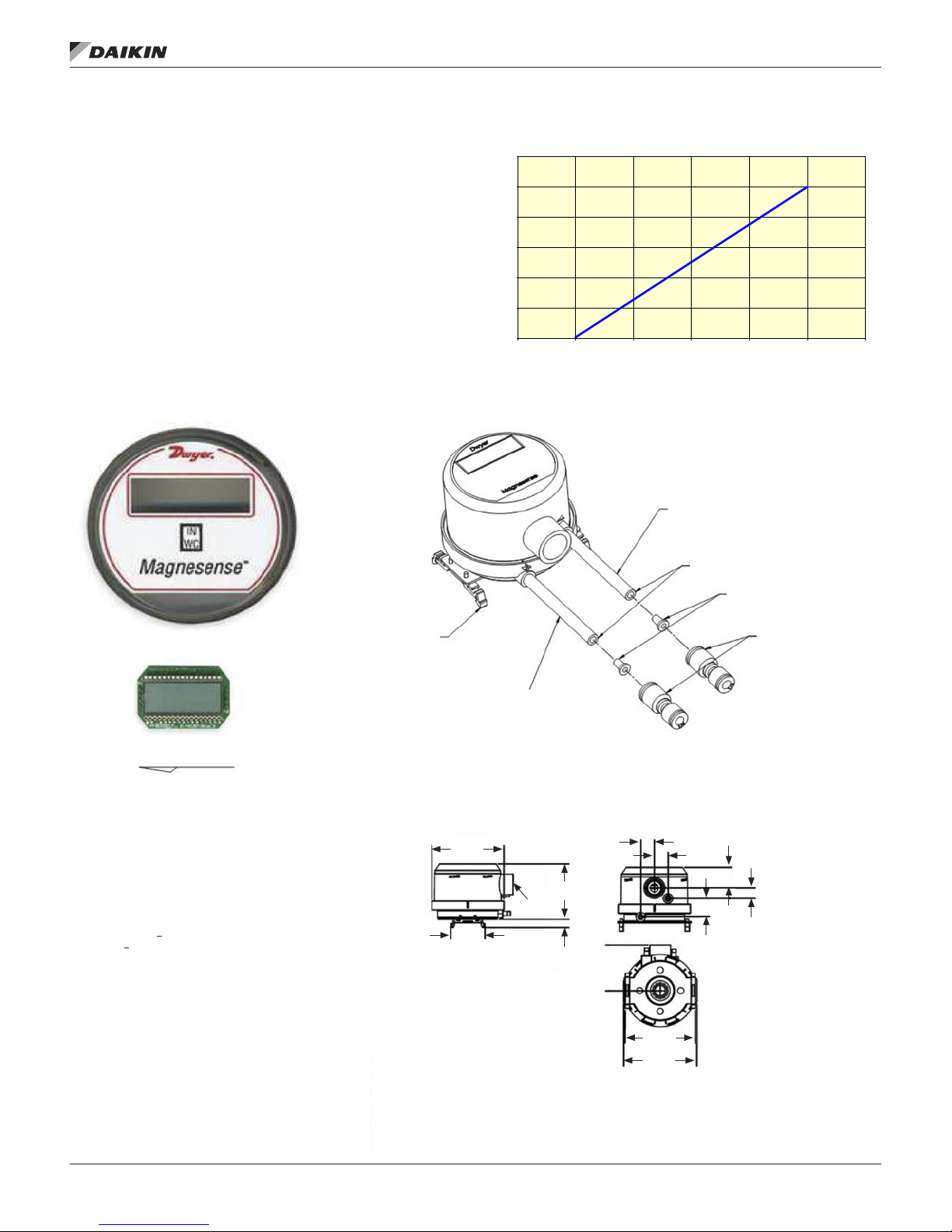
desCrIpTIon of operaTIon
Duct Pressure Sensor
Input Voltage - 24 VDC
Output - 4-20 mA
NOTE: The transducer output signal is 4-20mA however the
signal entering the VFD is converted to a DC voltage
signal via a 500 Ohm resistor on the Daikin MD
drives.
Figure 11: Duct Pressure Sensor
Figure 10: Duct Pressure Sensor Output
DC Volts
6
5
4
3
Inches W.C.
2
1
0
DC mA
Low Pressure (-) Port
Transducer provided with Dwyer #A-220 Vinyl
Tube (3'×5/16" O.D.) and Dwyer #A-3029-1
Quick Coupling Adapter (5/16"×1/4" O.D.),
Daikin McQuay #910122359. Coupler connects
to unit blue Vinyl Tubing (3/16" I.D.×1/4" O.D.),
Daikin McQuay #3499264-XX.
Tubes must be cut flush to insert fittings.
121086420
24201612840
Digital display is not included.
Order separately:
Daikin McQuay P/N #910117462
Dwyer P/N #A-441
Calibration: Factory set to 0.0" WC to +5.0" WC, where 4maDC is
output at 0.0" WC and 20maDC is output at +5" WC.
Jumper configuration: PJ3 = M position. PJ5 = N position. PJ7 = H20
position. Filter calibration change PJ3 position to = F, Factory Set = 1.
Return PJ3 to M position.
When required, use external loop resistor 499 OHMs, 1% Tol. Daikin
McQuay #044690105.
Accuracy: 0" to 5" WC
Range Accuracy: + 2%
Stability: +1% F.S./year
Temperature Limits: 0°F to 150° (-18°C to 66°C)
Pressure Limits: 1 psi maximum, operation; 10 psi, burst
Power Requirements: 10 to 35 VDC (2-wire)
Output Signals: 4 to 20 mA (2-wire)
Response Time: Field-adjustable 0.5 to 15 seconds time constant.
Provides a 95% response time of 1.5 to 45 seconds
Zero and Span Adjustments: Digital push button
Loop Resistance: Current output 0 to 1250 maximum
Current Consumption: 40 mA maximum
Display: 4 digit LCD (optional)
Electrical Connections: 4-20 mA, 2-wire; European-style terminal
block for 16 to 26 AWG
Electrical Entry: 1/2" NPS thread; accessory – cable gland for 5 to 10
mm diameter cable
Process Connection: 3/16" (5 mm) I.D. tubing; maximum O.D. 9 mm
Enclosure Rating: NEMA 4X (IP66)
Mounting Orientation: Diaphram in VERTICAL POSITION ONLY
Weight: 8.0 oz. (230 g)
Agency Approvals: CE and UL
DIN rail mounting
High Pressure (+) Port,
Transducer provided with Dwyer #A-220 Vinyl Tube
(3'×5/16" O.D.) and Dwyer #A-3029-1 Quick Coupling
Adapter (5/16"×1/4" O.D.), Daikin McQuay #910122359.
Coupler connects to unit red Vinyl Tubing (3/16" I.D.×1/4"
O.D.), Daikin McQuay #3499264-XX.
Ø3-7/16
[Ø87.31]
1/2 NPT
1-41/64
[41.71]
2-41/64
[67.24]
25/64
[9.96]
21/32
[16.67]
3-11/32
[84.84]
3-1/2
[88.9]
Insert fitting into tubes after tube
has been cut flush. Then insert
both into coupling.
Clear tubes must be
inserted into couplings at
least 1/2".
29/32
[23.02]
21/32
[16.67]
57/64
[22.62]
1/2
[12.7]
IM 919-3 • MICROTECH III CONTROLLER 10 www.DaikinApplied.com

desCrIpTIon of operaTIon
Building Pressure Sensor
Input Voltage - 24 VDC
Output - 4-20 mA
NOTE: The transducer output signal is 4-20mA however the
signal entering the VFD is converted to a DC voltage
signal via a 500 Ohm resistor on the Daikin MD
drives.
Figure 13: Building Pressure Sensor
DIN rail mounting
Figure 12: Building Pressure Sensor Output
DC Volts
0.3
0.2
0.1
0
Inches W.C.
-0.1
-0.2
-0.3
DC mA
Low Pressure (-) Port
Transducer provided with Dwyer #A-220 Vinyl
Tube (3'×5/16" O.D.) and Dwyer #A-3029-1
Quick Coupling Adapter (5/16"×1/4" O.D.),
Daikin McQuay #910122359. Coupler connects
to unit blue Vinyl Tubing (3/16" I.D.×1/4" O.D.),
Daikin McQuay #3499264-XX.
Tubes must be cut flush to insert fittings.
Insert fitting into tubes after tube
has been cut flush. Then insert
both into coupling.
Clear tubes must be
inserted into couplings at
least 1/2".
121086420
24201612840
Digital display is not included.
Order separately:
Daikin McQuay P/N #910117463
Dwyer P/N #A-441
Calibration: Factory set to 0.0" WC to =5.0" WC, where 4maDC is
output at 0.0" WC and 20maDC is output at +5" WC.
Jumper configuration: PJ3 = M position. PJ5 = N position. PJ7 = H20
position. Filter calibration change PJ3 position to = F, Factory Set = 1.
Return PJ3 to M position.
When required, use external loop resistor 499 OHMs, 1% Tol. Daikin
McQuay #044690105.
Accuracy: 0" to 5" WC
Range Accuracy: + 2%
Stability: +1% F.S./year
Temperature Limits: 0°F to 150° (-18°C to 66°C)
Pressure Limits: 1 psi maximum, operation; 10 psi, burst
Power Requirements: 10 to 35 VDC (2-wire)
Output Signals: 4 to 20 mA (2-wire)
Response Time: Field-adjustable 0.5 to 15 seconds time constant.
Provides a 95% response time of 1.5 to 45 seconds
Zero and Span Adjustments: Digital push button
Loop Resistance: Current output 0 to 1250 maximum
Current Consumption: 40 mA maximum
Display: 4 digit LCD (optional)
Electrical Connections: 4-20 mA, 2-wire; European-style terminal
block for 16 to 26 AWG
Electrical Entry: 1/2" NPS thread; accessory – cable gland for 5 to 10
mm diameter cable
Process Connection: 3/16" (5 mm) I.D. tubing; maximum O.D. 9 mm
Enclosure Rating: NEMA 4X (IP66)
Mounting Orientation: Diaphram in VERTICAL POSITION ONLY
Weight: 8.0 oz. (230 g)
Agency Approvals: CE and UL
High Pressure (+) Port,
Transducer provided with Dwyer #A-220 Vinyl Tube
(3'×5/16" O.D.) and Dwyer #A-3029-1 Quick Coupling
Adapter (5/16"×1/4" O.D.), Daikin McQuay #910122359.
Coupler connects to unit red Vinyl Tubing (3/16" I.D.×1/4"
O.D.), Daikin McQuay #3499264-XX.
Ø3-7/16
[Ø87.31]
1-41/64
[41.71]
1/2 NPT
2-41/64
[67.24]
25/64
[9.96]
21/32
[16.67]
3-11/32
[84.84]
3-1/2
[88.9]
21/32
[16.67]
57/64
[22.62]
29/32
[23.02]
1/2
[12.7]
www.DaikinApplied.com 11 IM 919-3 • MICROTECH III CONTROLLER
Mamac Panel-Mounted Pressure Transducer
desCrIpTIon of operaTIon
WARNING
Electric shock hazard. Can cause personal injury or equipment
damage.
This equipment must be properly grounded. Connections and
service to the MicroTech III control panel must be performed
only by personnel that are knowledgeable in the operation of
the equipment being controlled.
The following describes the proper wiring of these pressure
transducers with mA output.
1. Remove the terminal block by carefully pulling it off the
circuit board.
2. Locate the [+] and [-] terminal markings on the board.
3. Attach the supply voltage to the [+] lead.
4. Connect the 4-mA output ([-] terminal) to the controller’s
input terminal.
5. Ensure that the power supply common is attached to the
common bus of the controller.
6. Re-insert the terminal block to the circuit board and apply
power to the unit.
7. Check for the appropriate output signal using a DVM set
on DC milliamps connected in series with the [-] terminal.
Specications
Accuracy: ± 1% FS
Overpressure: 10 PSID
Supply Voltage: 12–40 VDC
12–35 VAC (VDC output units only)
Supply Current: VDC units — 10mA max.
mA units — 20 mA max.
Enclosure: 18 Ga. C R Steel NEMA 4 (P-65) or panel-mount
chassis
Finish: Baked-on enamel PMS2GR88B
Compensated Temp Control: 25°F – 175°F (-18°C – -80°C)
T.C. Error: ± 0.0125%/°F (± 0.02%/°C)
Operating Temp Range: 0°F – 175°F (-18°C – 80°C)
Media Compatibility: Clean dry air or any inert gas
Environmental: 10 – 90% RH Non-condensing
Wire Size: 12 Ga. max.
Load Impedance: 1.6K ohms max. at 40VDC (mA output units)
1K ohms min. VDC output units)
Weight: Enclosure — 1.0 lbs. (45 kg)
Panel-mount — 0.5 lbs. (25 kg)
Figure 14: Mamac Panel-Mounted Pressure Transducer Dimensions
IM 919-3 • MICROTECH III CONTROLLER 12 www.DaikinApplied.com
desCrIpTIon of operaTIon
Actuators
The actuators are controlled by an analog signal from the
unit controller. Damper actuators utilize a 0-10VDC analog
signal while modulating heating/cooling valve actuators utilize
a 210VDC signal. Spring-return actuators are used for the
0 - 30% outdoor air and economizer dampers. The mixing
dampers are normally closed to the outside air.
Figure 15: Actuator Wiring Diagram
Variable Frequency Drives (VFD’s)
When controlling discharge, return or exhaust fan, energy
recovery wheel or evaporating condenser fan variable
frequency drives, the MicroTech III controller uses an internal
ModBus communications channel for control and monitoring of
the Variable Frequency Drives.
Figure 16: VFD Wiring Diagram
Smoke Detectors
Field installed smoke detectors in the return air ductwork or
the supply air ductwork can be coordinated with the units
operation through the main controller’s binary input, DI4. This
input is wired to TB2 and the supply air smoke detector can be
wired between terminals 103 and 104 and the return air smoke
detector can be wired between terminals 104 and 105. The T2
transformer supplies 24 V (ac) across each of these terminals
and a dry set of contacts can be wired to these terminals
respectively. This and additional wiring information can be seen
on the input wiring schematics at line number 220.
Figure 17: Smoke Detector Wiring Diagram
NOTE: Factory smoke detectors are wired the same as eld
mounted.
ECM (Electronically Commutated Motor)
fan/motor
The Rebel unit is equipped with a direct drive, ECM
(Electronically Commutated Motor) fan/motor combination
with a built in inverter. When equipped, the exhaust fan will
be the same. The Maverick II unit also has this as an exhaust
fan option. The MTIII controller uses an internal Modbus
communications channel for control and monitoring of the ECM
fan/motor.
www.DaikinApplied.com 13 IM 919-3 • MICROTECH III CONTROLLER

ConTroller InpuTs/ouTpuTs
Table 4: RTU/MPS/DPS/DPH Main Control Board I/O
ConTroller InpuTs/ouTpuTs
PolyCool 600 Main Controller — RTU & MPS & DPS Pos. 1 = 0, 2, 3 or 4
# Point Comments Cong. Code Condition
AI 1 Discharge Temperature 10K Thermistor (STD) All
AI 2 Return Temperature 10K Thermistor (STD) 8 <> 2 or 8 = 2 and 20 > 0
AI 3 Outdoor Temperature 10K Thermistor (STD) All
# DI AI DO AO Point Comments Cong. Code Condition
X 1 X CO2 /Min OA/OA CFM 0–10VDC or 4–20 mA 8 = 1, 2 3, 5, 6, 7, 8 or 9
X 2 X Low Pressure 1 and 2
X 2 X Chilled Wtr 2–10 VDC 3 = 2 or 3 = 3
X 2 X Ent Fan & Lvg Coil T 10K Thermistor 1 = 3 or 4 & 19 = 1
X 3 X Space Temperature 10K Thermistor (STD) All
X 4 X Zone Setpoint 5–15 kOhm All
X 4 X DAT Reset 0–10 VDC / 4–20 mA 2 = 1 or 2
X 5 X Enthalpy & Freeze Sw
X 5 X Relative Humidity 0–10 VDC or 4–20 mA 1 = 3 or 4
X 6 X Ent Fan & Lvg Coil T
X 6 X Duct Static Pressure 4–20 mA 1 = 2, 3 or 4 & 15 = 1–6
X 7 X OA Damper 0–10 VDC RPS 0-10 VDC MPS 8 = 1, 2, 3, 5, 6, 7, 8 or 9
X 8 X Building Static Pressure 4–20 mA 1 = 2, 3, 4 & 16 = 8, 9, A or F
X 8 X OAD End Switch Input Dry Contact 1 = 0 & 8 = 8 or 9
# Point Comments Cong. Code Condition
DI 1 Air Flow Switch / DHL (R63) Dry Contact All
DI 2 Filter Switch Dry Contact All
# Point Comments Cong. Code Condition
DI 3 Remote START / STOP External 24V All
DI 4 Emergency OFF / DHL (R63) External 24 V All
# Point Comments Cong. Code Condition
DI 5 High Pressure 1 115 VAC Input 3 = 1 & 4 > 1 & 4 < H
DI 5
Standard Comp High Pressure
DI 6 High Pressure 2 115 VAC Input 3 = 1 & 4 > 1 & 4 < H
DI 6 Enthalpy Switch 115 VAC Input 1 = 3 or 4 & 8 = 3, 6, 8 or 9
1. When used for LP1 and LP2, LP1 is considered CLOSED when resistance value is 0–799 or 1250–1800. Otherwise LP1 is considered OPEN. LP2 is considered
CLOSED when the resistance value is 0–1249, otherwise LP2 is considered OPEN.
2. Enthalpy switch is considered CLOSED when resistance value is 0–799 or 1250–1800. Otherwise it is considered OPEN. Freezestat is considered CLOSED when
the resistance value is 0–1249, otherwise it is considered OPEN.
I/O Cong. Code Condition
Analog Inputs — NTC
Universal Inputs/Outputs
1
2
1K & 2K Ohm Input 3 = 1 & 4 > 1 & 4 < H
1 = 0 or 2
1K & 1.5K Ohm Input
Enth: 8 = 3, 6, 8 or 9
Frz: 3 = 2, 3 = 3, 10 = 1 or 10 = 5
10K Thermistor (STD) — Gas or
Electric Heat & Dehum
1 = 0 & 19 = 1
Digital Inputs — Dry Contacts
Digital Inputs — 24V
Digital Inputs — 115V
(HP3 / HP5)
1 = 3 or 4
IM 919-3 • MICROTECH III CONTROLLER 14 www.DaikinApplied.com
Table 4 continued: RTU/MPS/DPS/DPH Main Control Board I/O
I/O Cong. Code Condition
PolyCool 600 Main Controller — RTU & MPS & DPS Pos. 1 = 0, 2, 3 or 4
Digital Outputs — Relay (SPST, Normally Open, 230 VAC 3 Amp
# Point Comments Cong. Code Condition
DO 1 Compressor 1 / GC Stg 1 3 = 1
DO 1 INV Comp ON / OFF Currently Not Used
DO 1 Comp 1 3 = 5 & 4 = 4, 7, A, D or J
DO 1 VFD Comp 1 Enable 3 = 4
DO 2 Compressor 3 / GC Stg 2
DO 2 STD3 Compressor 3 = 4 & 4 = M
DO 2 Unld 2 Comp 1 4 = 4 and 7 = 2, 3, 4 or 5
DO 2 Comp 3 3 = 5 & 4 = 7, A, D or J
DO 3 Compressor 2 / GC Stg 3
DO 3 Heat Stage 1 1 = 3 or 4 & 10 = 2
DO 3 Gas Heat (ON/OFF) 1 = 3 or 4 10 = 7 or 8
DO 3 SCR Enable 1 1 = 3 or 4 & 10 = 6
DO 3 Comp 2 3 = 4 & 4 = 4, D
DO 3 VFD Comp 2 Enable 3 = 5
DO 4 Compressor 4 / GC Stg 4
DO 4 Unld 2 Comp 2 4 = 4 and 7 = 2, 3, 4 or 5
DO 4 Heat Stage 2 1 = 3 or 4 & 10 = 2 & 11 > 1
DO 4 Comp 4
DO 5 Supply Fan All
DO 6 Cond Fan Output C
DO 6 HGBP Vavle 1 = 2 & 3 = 1 & 28 = 2
DO 6 Constant Speed Enthalpy Wheel Energy Recovery 20 = 1 or 6 & 30 = 3, 4, 5, 6
DO 7 Cond Fan Output A 2 Relays, CF3 & CF4 3 = 1 & 4 > 1 & 4 < F
DO 7 Generic Comp Stg 7 3 = 1 & 4 = 1 & 5 > 6
DO 7 Heat Stage 3 1 = 3 or 4 & 10 = 2 & 11 > 2
DO 8 Cond Fan Output B 2 Relays, CF5 & CF6
DO 8 Generic Comp Stg 8 3 = 1 & 4 =1 & 5 > 7
DO 8 Heat Stage 4 1 = 3 or 4 & 10 = 2 & 11 > 3
Digital Outputs – Solid State Relays, 24-230 VAC, 0.5 A
# Point Comments Cong. Code Condition
DO 9 Alarm All
DO 10 Fan Operation All
ConTroller InpuTs/ouTpuTs
1 = 3 or 4 &
3 = 4 &
4 = L or M &
24, 25, 26 = 003–015
3 = 1 & any of the following:
4 = 7, 9, A, D, E or
4 = 3 & 1 = 2 or
4 = 3 & 1 = 0 & 27 = 0 or 1 or
4 = 1 & 5 > 1
3 = 1 & any of the following:
4 > 1 & 4 < F or
4 = 1 and 5 > 2
3 = 1 & any of the following:
4 = 7, A, E or 4 = 1 & 5 > 3 or
1 = 0 & 4 = 3 & 27 = 2
[3 = 4 & 4 = D & 5 = 1] or
[3 = 5 & 4 = 7, J & 5 = 2] or
[3 = 5 & 4 = A & 5 = 3]
1 = 0 & 3 = 1 & 4 > 1 &
24, 25, 26 = (060–105) &
(27 = 0 or 27 = 1) & (7 ≠ 2, 3, 4 or 5)
1 = 0 & 3=1 & 4 > 1 & 4 < D &
24, 25, 26 = (075–105) &
(27 = 0 or 27 = 1) or 1 = 0 &
3 = 1 & 4 > & 4 < D &
24, 25, 26 = (075 or 090–140) &
27 = 2 or 1 = 2 & 3 = 1 &
24, 25, 26 = 030, 035, 040 or 050
Note: If 7 = 2, 3, 4 or 5
then this applies only if 24, 25, 26
is greater than 110.
www.DaikinApplied.com 15 IM 919-3 • MICROTECH III CONTROLLER
ConTroller InpuTs/ouTpuTs
Table 5: SCU Main Control Board I/O
I/O Cong. Code Condition
PolyCool 600 Main Controller – SCU Pos. 1=1
Analog Inputs – 10K NTC
# Point Comments Cong. Code Condition
AI 1 Discharge Temperature 10K Thermistor (STD) All
AI 2 Return Temperature 10K Thermistor (STD) All
AI 3 Outdoor Temperature 10K Thermistor (STD) All
Universal Inputs/Outputs
# DI AI DO AO Point Comments Cong. Code Condition
X 1 X Entering WaterTemperature 10K Thermistor (STD) 3 = 1 & 4 > 3
X 2 X Low Pressure 1 and 2
X 2 X Chilled Wtr 0–10 VDC 3 = 2 or 3 = 3
X 3 X Space Temperature 10K Thermistor (STD) All
X 4 X Zone Setpoint 5–15 kOhm 2 = 0
X 4 X DAT Reset 0–10 VDC / 4–20 mA 2 = 1
X 5 X Enthalpy & Freeze Sw
X 6 X Bypass Valve 2–10 VDC 3 = 1
X 6 X Water Regulating Valve 2–10 VDC 3 = 1 & 8 <> 4 & 22 =1
X 7 X Economizer
X 8 X Mixed Air Temp 10K Thermistor (STD) All
# Point Comments Cong. Code Condition
DI 1 Air Flow Switch Dry Contact All
DI 2 Filter Switch Dry Contact All
# Point Comments Cong. Code Condition
DI 3 Remote START / STOP External 24V All
DI 4 Emergency OFF External 24V All
# Point Comments Cong. Code Condition
DI 5 High Pressure 1 115 VAC Input 3 = 1 & 4 > 1 or 3 = 4
DI 6 High Pressure 2 115 VAC Input 3 = 1 & 4 > 1
Digital Outputs — Relay (SPST, Normally Open, 230 VAC 3 Amp
# Point Comments Cong. Code Condition
DO 1 Compressor 1 3 = 1
DO 2 Compressor 3 3 = 1 & 4 > 4
DO 3 Compressor 2 3 = 1
DO 4 Compressor 4 3 = 1 & 4 > 6
DO 5 Supply Fan All
DO 6 NA
DO 7 Outdoor Damper OPEN / CLOSE 8 <> 3
DO 8 Pump ON/OFF 3 = 1 & 4 > 1
Digital Outputs – Solid State Relays, 24-230 VAC, 0.5 A
# Point Comments Cong. Code Condition
DO 9 Alarm All
DO 10 Fan Operation All
1. When used for LP1 and LP2, LP1 is considered CLOSED when resistance value is 0–799 or 1250–1800. Otherwise LP1 is considered OPEN. LP2 is considered
CLOSED when the resistance value is 0–1249, otherwise LP2 is considered OPEN.
2. Enthalpy switch is considered CLOSED when resistance value is 0–799 or 1250–1800. Otherwise it is considered OPEN. Freezestat is considered CLOSED when
the resistance value is 0–1249, otherwise it is considered OPEN.
1
2
Digital Inputs — Dry Contacts
Digital Inputs — 24V
Digital Inputs — 115V
1K & 2K Ohm Input 3 = 1 & 4 > 3
1K & 1.5K Ohm Input
0–10 VDC (Air Econo) / 2–10 VDC
(Water Econo)
Frz: 3 = 2, 3 = 3, 8 = 4, 10 = 1, 10 = 5
Enth: 8 = 3
8 = 3 or 8 = 4
IM 919-3 • MICROTECH III CONTROLLER 16 www.DaikinApplied.com
ConTroller InpuTs/ouTpuTs
Table 6: RTU Expansion Module A I/O
RTU — Expansion Module A Pos. 1 = 0
Design Flow, RPS Energy Recovery, RPS Dehumidication, 5 or 6 Compressors
# DI AI DO AO Point Comments Cong. Code Condition
X 1 X LSCRH Valve 0-10 VDC 28 = 4 or 5
X 2 X Reheat #1 0-10 VDC 28 = 2
X 3 X Reheat #2 0-10 VDC NA
X 4 X Supply Temp Leaving Wheel 10K Thermistor (STD) 20 > 0
X 4 X DesignFlo 1 Ratiometric 9 > 0
X 5 X Exhaust Temp Leaving Wheel 10K Thermistor (STD) 20 > 1
X 5 X DesignFlo 2 Ratiometric 9 > 0
X 6 X Relative Humidity 0-10 VDC or 4-20 mA All
X 7 X High Refrigerant Pressure 1 (future) Ratiometric input required NA
X 8 X High Refrigerant Pressure 2 (future) Ratiometric input required NA
Digital Outputs — Relay (SPST, Normally Open, 230 VAC 3 Amp)
# Point Comments Cong. Code Condition
DO 1 Compressor 5 / GC Stg 5 3 = 1 & 4 = A or 3 = 1 & 4 = 1 & 5 > 4
DO 2 Compressor 6 / GC Stg 6 3 = 1 & 4 = A or 3 = 1 & 4 = 1 & 5 > 6
DO 3 Reheat Output 28 = 1, 2, or 5
DO 4 Constant Speed Enthalpy Wheel Energy Recovery 20 = 1 or 6
# Point Comments Cong. Code Condition
DO 5 Bypass Damper CLOSED Energy Recovery 20 > 0 & 8 <> 2
DO 6 Bypass Damper OPEN Energy Recovery 20 > 0 & 8 <> 2
I/O Cong. Code Condition
Universal Inputs/Outputs
Digital Outputs — Triac (24 VAC, 0.5 Amp)
Table 7: SCU Expansion Module A I/O
All Units: (CO2/Remote Min OA, Waterow Switch, Head Pressure Control, 5 or 6 Compressors)
SCU — Expansion Module A Pos. 1 = 1
# DI AI DO AO Point Comments Cong. Code Condition
X 1 X CO2 / Min OA / OA CFM 0–10 VDC or 4–20 mA 8 = 3 & 9 = 5 for OA CFM
X 2 X Duct Static Pressure 1 4–20 mA 1 = 1 & 15 = 6
X 3 X OA CFM 0–10 VDC or 4–20 mA 8 = 3 or 6 & 9 = 6 for OA CFM
X 4 NA
X 5 X Waterow Switch Dry Contact 3 = 1 & 4 > 1 & 22 = 0
X 6 X Relative Humidity
X 7 X High Refrigerant Pressure 1 Ratiometric input required 22 = 1
X 8 X High Refrigerant Pressure 2 Ratiometric input required 22 = 1
# Point Comments Cong. Code Condition
DI OAD End Switch Input 115 VAC Input 1 = 1 & 8 = 8 or 9
Digital Outputs – Relay (SPST, Normally Open, 230 VAC 3 Amp)
# Point Comments Cong. Code Condition
DO 1 Compressor 5 3 = 1 & 4 > A
DO 2 Compressor 6 3 = 1 & 4 > A
DO 3 Compressor 7 3 = 1 & 4 = F or G
DO 4
# Point Comments Cong. Code Condition
DO 5 Compressor 8 3 = 1 & 4 = F or G
DO 6
I/O Cong. Code Condition
Universal Inputs/Outputs
0–10 VDC or 4–20 mA —
Dehumidication
Digital Input – 115V-230V
Digital Outputs – Triac (24 VAC, .5 Amp)
All
www.DaikinApplied.com 17 IM 919-3 • MICROTECH III CONTROLLER
ConTroller InpuTs/ouTpuTs
Table 8: RTU/MPS/DPS/DPH Expansion Module B I/O
Heating, F&BP Dampers, MPS Dehumidication, MPS/DPS Energy Recovery, MPS Staged Exhaust Fan
RTU, MPS & DPS – Expansion Module B Pos. 1=0,2,3o4
# DI AI DO AO Point Comments Cong. Code Condition
X 1 X FSG Ign_Pilot Input (FSG-8) Dry Contact 1 = 0 & 10 = 4
X 1 X Ent Fan & Lvg Coil T
X 2 X Gas Heat LS1 Switch Dry Contact 1 = 0 & 10 = 4
X 2 X Reheat #1 0–10 VDC 1 = 2 & 28 = 2
X 3 X Gas Heat LS2 Switch Dry Contact 1 = 0 & 10 = 4
X 3 X OA Flow 0–10 VDC or 4–20 mA
X 4 X FSG Alarm Input (FSG-3) 1=0 & (10=3 or 10=4)
X 4 X Supply Temp Leaving Wheel 10K Thermistor (STD) 1 = 2, 3 or 4 & 20 > 0 & 30 ≠ 3, 4, 5 or 6
X 5 X Exhaust Temp Leaving Wheel 10K Thermistor (STD) 1 = 2, 3 or 4 & 20 > 0 & 30 ≠ 3, 4, 5 or 6
X5 X Duct Static Pressure 1 4–20 mA 1 = 0 & 15 = 6
X 6 X Relative Humidity 0–10 VDC or 4–20 mA 1 = 2
X 7 X Heating Valve 2–10 VDC
X 7 X SCR 0–10 VDC 1 = 0, 1 or 2 & 10 = 6
X 8 X F & BP Damper 0–10 VDC 1 = 0 or 1 & 3 = 3 or 10 = 1
X8 X Constant Speed Enthalpy Wheel Energy Recovery 1 = 2 & 20 =1 or 6
# Point Comments Cong. Code Condition
DI OAD End Switch Input 115 VAC Input 1 = 2 & 8 = 8 or 9
DI Freezestat Switch 115 VAC Input
Digital Outputs — Relay (SPST, Normally Open, 230 VAC 3 Amp)
# Point Comments Cong. Code Condition
DO 1 Gas Heat (ON/OFF) 1 = 0 or 2 10 =3 , 4, 7 or 8
DO 1 Heat Stage 1 1 = 0, 1 or 2 & 10 = 2
DO 1 SCR Enable 1 1 = 0, 1 or 2 & 10 = 6
DO 1 Constant Speed Enthalpy Wheel Energy Recovery 1 = 3 or 4 & 20 = 1 or 6 & 30 = 1 or 2
DO 2 Pilot Gas (ON/OFF) 10 = 4
DO 2 Heat Stage 2 1 = 0, 1 or 2 & 10 = 2 & 11 > 1
DO 2 SCR Enable 2 1 = 0, 1 or 2 & 10 = 6
DO 3 Heat Stage 3 1 = 0, 1 or 2 & [10 = 8 or 10 = 2 & 11 > 2]
DO 4 Heat Stage 4 1 = 0, 1 or 2 & [10 = 8 or 10 = 2 & 11 > 3]
# Point Comments Cong. Code Condition
DO 5 Heat Stage 5 1 = 0, 1 or 2 & 1 = 0 & 10 = 2 & 11 > 4
DO 5 Exh Fan Stage 1 1 = 2 & 16 = C, D or E
DO 5 Bypass Damper CLOSED Energy Recovery
DO 6 Heat Stage 6 1 = 0 & 10 = 2 & 11 > 5
DO 6 Exh Fan Stage 2 1 = 2 & 16 = D or E
DO 6 Bypass Damper OPEN Energy Recovery
I/O Cong. Code Condition
Universal Inputs/Outputs
10K Thermistor (STD) — Gas or
Electric Heat & Dehum
Digital Input — 115V-230V
Digital Outputs — Triac (24 VAC, .5 Amp)
1 = 2, 3 or 4 & 8 = 1, 2, 3, 5, 6 or 7 & 9 = 6
1 = 0, 1 or 2 & 10 = 1, 10 = 3, 10 = 4, 10 =
(1 = 2) & (19 = 1)
& 30 ≠ 3, 4, 5 or 6
5, 10 = 7 or 10 = 8
1 = 3 or 4 & 10 = 5 & 8 = 8 or 9 &
30 ≠ 3, 4, 5 or 6
1 = 2, 3 or 4 & 20 > 0 & 8 = 3 or 6 &
30 ≠ 3, 4, 5 or 6
1 = 2, 3 or 4 & 20 > 0 & 8 = 3 or 6 &
30 ≠ 3, 4, 5 or 6
IM 919-3 • MICROTECH III CONTROLLER 18 www.DaikinApplied.com
ConTroller InpuTs/ouTpuTs
Table 9: SCU Expansion Module B I/O
SCU — Expansion Module B Pos. 1 = 1
# DI AI DO AO Point Comments Cong. Code Condition
X 1 X Low Pressure 7 3 = 1 & 4 = G & 21 = 0
X 2 X Low Pressure 8 3 = 1 & 4 = G & 21 = 0
X 3 X High Pressure 7 3 = 1 & 4 = G & 21 = 0
X 4 X High Pressure 8 3 = 1 & 4 = G & 21 = 0
X 5
X 6
X 7 X Heating Valve 2–10 VDC 10 = 1 or 10 = 5
X 7 X SCR 0–10 VDC 10 = 6
X 8 X F & BP Damper 0–10 VDC 3 = 3 or 10 = 1
Digital Outputs — Relay (SPST, Normally Open, 230 VAC 3 Amp)
# Point Comments Cong. Code Condition
DO 1 Heat Stage 1 10 = 2
DO 1 SCR Enable 1 10 = 6
DO 2 Heat Stage 2 10 = 2 & 11 > 1
DO 2 SCR Enable 2 10 = 6
DO 3 Heat Stage 3 10 = 2 & 11 > 2
DO 4 Heat Stage 4 10 = 2 & 11 > 3
# Point Comments Cong. Code Condition
DO 5 Heat Stage 5 10 = 2 & 11 > 4
DO 6 Heat Stage 6 10 = 2 & 11 > 5
I/O Cong. Code Condition
Heating, F & BP Dampers
Universal Inputs/Outputs
Digital Outputs — Triac (24 VAC, 0.5 Amp)
www.DaikinApplied.com 19 IM 919-3 • MICROTECH III CONTROLLER
ConTroller InpuTs/ouTpuTs
Table 10: RTU - Expansion Module C I/O
RTU Evaporative Condensing, VFD Compressors
RTU — Expansion Module C
# DI AI DO AO Point Comments Cong. Code Condition
X 1 X PS1 Pos. 1 = 0 & 7 = 2, 3, 4 or 5 & 4 = 4 or E
X 1 X Comp 1 0–5 VDC
X 1 X VFD (Comp 1) 0–10 VDC 3 = 4
X 1 X VFD (Comp 2) 0–10 VDC 3 = 5
X 2 X PS2 Pos. 1 = 0 & 7 = 2, 3, 4 or 5 & 4 = 4 or E
X 3 X Comp 2 0–5 VDC 3 = 9 or 10 & Unit Size ≠ 120
X 3 X Sump Temperature
X 3 X Comp 1 Oil Status 3 = 4
X 3 X Comp 2 Oil Status 3 = 5
X 4 X Conductivity 4–20 mA — Evaporative Condensing Pos. 1 = 0 & 7 = 2, 3, 4 or 5
X 4 X Com 1 Alm Dry Contact
X 4 X Comp 1 Status 3 =4
X 4 X Comp 2 Status 3 = 5
X 5 X LP1 Pos. 1 = 0 & 7 = 2, 3, 4 or 5 & 4 = 4 or E
X 5 X Comp 2 Alm Dry Contact 3 = 9 or 10 & Unit Size ≠ 120
X 6 X LP2 Pos. 1 = 0 & 7 = 2, 3, 4 or 5 & 4 = 4 or E
X 6 X Disch. Refrig. Pressure Ckt1
X 6 X Disch. Refrig. Pressure Ckt1
X 7 X Separator Flush Valve 0-10VDC Pos. 1 = 0 & 7 = 2, 3, 4 or 5
X 7 X Disch. Refrig. Pressure Ckt2
X 7 X Disch. Refrig. Pressure Ckt2
X 8 X Sump Water Level Switch Dry Contact
X 8 X Comp 1 DLT
X 8 X Comp 2 DLT
Digital Outputs — Relay (SPST, Normally Open, 230 VAC 3 Amp)
# Point Comments Cong. Code Condition
DO 1 SV1 Pos. 1 = 0 & 7 = 2, 3, 4 or 5 & 4 = 4 or E
DO 1 Cond Coil Solenoid Ckt1
DO 1 Cond Coil Splitter Solenoid Circuit 1 3 = 4 or 5
DO 2 Unld 1 Comp 1 Pos. 1 = 0 & 7 = 2, 3, 4 or 5 & 4 = 4 or E
DO 2 Cond Coil Solenoid Ckt2 3 = 9 or 10 & Unit Size ≠ 120
DO 2 Cond Coil Splitter Solenoid Circuit 2 3 = 4 or 5
DO 3 SV2 Pos. 1 = 0 & 7 = 2, 3, 4 or 5 & 4 = 4 or E
DO 4 Unld 1 Comp 2 Pos. 1 = 0 & 7 = 2, 3, 4 or 5 & 4 = 4 or E
DO 4 VFD Comp 1 Emergency Stop 3 = 4
DO 4 VFD Comp 2 Emergency Stop 3 = 5
# Point Comments Cong. Code Condition
DO 5 Drain Valve Evaporative Condensing
DO 5 Comp 5
DO 6 Sump Pump Evaporative Condensing
DO 6 Comp 6 3 = 5 & 4 = A & 5 =3
I/O Cong. Code Condition
Universal Inputs/Outputs
[3 = 10 & Unit Size ≠ 120] or
[3 = 9 & Unit Size = 120]
10K Thermistor (STD) — Evaporative
Digital Outputs — Triac (24 VAC, 0.5 Amp)
Condensing
Ratiometric input required
(0.5–4.5 VCD: 0–700 psi)
Ratiometric input required
(0.5–4.5 VCD: 0–700 psi)
Ratiometric input required
(0.5–4.5 VCD: 0–700 psi)
Ratiometric input required
(0.5–4.5 VCD: 0–700 psi)
Resistance Input
(T = 0.4637 R–431.72)
Resistance Input (T = 0.4637
R–431.72)
Pos. 1 = 0 & 7 = 2, 3, 4 or 5
[3 = 10 & Unit Size ≠ 120] or
[3 = 9 & Unit Size = 120]
[3 = 10 & Unit Size ≠ 120] or
[3 = 9 & Unit Size =1 20]
3 = 4 or 5
3 = 9 or 10 & Unit Size ≠ 120
3 = 4 or 5
3 = 4
3 = 5
[3 = 10 & Unit Size ≠ 120] or
[3 = 9 & Unit Size = 120]
[3 = 5 & 4 = 7 & 5 = 1] or
[3 = 5 & 4 = J & 5 = 2] or
[3 = 5 & 4 = A & 5 = 3]
IM 919-3 • MICROTECH III CONTROLLER 20 www.DaikinApplied.com

ConTroller InpuTs/ouTpuTs
Table 11: SCU Expansion Module C I/O
SCU — Expansion Module C Pos. 1 = 1
One Compressor Per Circuit
# DI AI DO AO Point Comments Cong. Code Condition
X 1 X Low Pressure 3 Dry Contact 3 = 1 & 4 = 5, 6, 8, 9, B or C & 21 = 0
X 2 X Low Pressure 4 Dry Contact 3 = 1 & 4 = 8, 9, B or C & 21 = 0
X 3 X High Pressure 3 Dry Contact 3 = 1 & 4 = 5, 6, 8, 9, B or C & 21 = 0
X 4 X High Pressure 4 Dry Contact 3 = 1 & 4 = 8, 9, B or C & 21 = 0
X 5 X Low Pressure 5 Dry Contact 3 = 1 & 4 = B or C & 21 = 0
X 6 X Low Pressure 6 Dry Contact 3 = 1 & 4 = B or C & 21 = 0
X 7 X High Pressure 5 Dry Contact 3 = 1 & 4 = B or C & 21 = 0
X 8 X High Pressure 6 Dry Contact 3 = 1 & 4 = B or C & 21 = 0
Digital Outputs — Relay (SPST, Normally Open, 230 VAC 3 Amp)
# Point Comments Cong. Code Condition
DO 1
DO 1
DO 2
DO 2
DO 3
DO 4
# Point Comments Cong. Code Condition
DO 5
DO 6
I/O Cong. Code Condition
Universal Inputs/Outputs
Digital Outputs — Triac (24 VAC, 0.5 Amp)
www.DaikinApplied.com 21 IM 919-3 • MICROTECH III CONTROLLER
ConTroller InpuTs/ouTpuTs
Table 12: DPS/DPH Expansion Module D I/O
I/O Cong. Code Condition
Expansion Module D Pos. 1=3or4
# Point Comments Cong. Code Condition
AI 1 Indoor Refrigerant Temperature (IRT) 10K Thermistor (STD) 1 = 4 & 30 = 3, 4, 5 or 6
AI 2
AI 3
# DI AI DO AO Point Comments Cong. Code Condition
X 1 X
X 2 X
X 3 X
X 4 X
X 5 X Heating Valve
X 6 X
X 7 X
X 7 X INV Compressor Body Temperature 100K Thermistor (HT) 24, 25, 26 = 0, 1, 5
X 8 X Reheat Output 0–10 VDC 28 = 2
X 9 X Supply Temp Leaving Wheel 10K Thermistor (STD) 20 > 0 & 30 = 3, 4, 5 or 6
X 10 X Exhaust Temp Leaving Wheel 10K Thermistor (STD) 20 > 0 & 30 = 3, 4, 5 or 6
X 11 X OA Flow 0–10 VDC or 4–20 mA
X 12 X Freezestat Switch 0-5 VDC 10 =5 & 8 = 8 or 9 & 30 = 3, 4, 5 or 6
# Point Comments Cong. Code Condition
DI Freezestat Switch 115 VAC Input 10 = 5 & 8 = 3 or 6
DI OAD End Switch Input 115 VAC Input 8 = 8 or 9
# Point Comments Cong. Code Condition
DO 1 INV Board Power Up
DO 2
DO 3 Bypass Solenoid Valve (SVB)
DO 4 4 Way Reversing Valve (4WV) 1 = 4
# Point Comments Cong. Code Condition
DO 5 Bypass Damper CLOSED Energy Recovery 20 > 0 & 8 = 3 or 6 & 30 = 3, 4, 5 or 6
DO 6 Bypass Damper OPEN Energy Recovery 20 > 0 & 8 = 3 or 6 & 30 = 3, 4, 5 or 6
Outdoor Refrigerant Temperature
Outdoor Coil Defrost Temperature
Compressor Suction Pressure Sensor
Compressor Discharge Pressure
INV Compressor Discharge Line
Refrigerant Temperature (DRT1)
STD3 Compressor Discharge Line
Refrigerant Temperature (DRT3)
Compressor Suction Line Refrigerant
Outdoor Coil Defrost Temperature
Digital Outputs — Relay (SPST, Normally Open, 230 VAC 3 Amp)
Refrigerant Receiver Gas Line
(ORT)
(DFT)
(PTS)
Sensor (PTD)
Temperature (SRT)
(DFT)
Solenoid Valve (SVR)
Digital Outputs — Triac (24 VAC, 0.5 Amp)
Analog Inputs — NTC
10K Thermistor (STD) 1 = 4 & 30 = 3, 4, 5 or 6
10K Thermistor (STD) 1 = 4 & 30 = 3, 4, 5 or 6
Universal Inputs/Outputs
0.5–4.5 VDC 0–350 psi
0.5–4.5 VDC 0–700 psi
100K Thermistor (HT)
100K Thermistor (HT) 4 = M
Gas 2–10 VDC HW/STM 2–10 VDC
10K Thermistor (STD)
10K Thermistor (STD) 1 = 4 & 30 = 1 or 2
Digital Input — 115V-230V
SCR 0–10 VDC
10 = 5, 6 or 7
8 = 1, 2, 3, 5,6 or 7 & 9 = 6 &
30 = 3, 4, 5 or 6
1 = 4
IM 919-3 • MICROTECH III CONTROLLER 22 www.DaikinApplied.com

ConTroller InpuTs/ouTpuTs
Table 13: RTU/SCU/MPS/DPS/DPH Expansion Module E I/O
I/O Cong. Code Condition
Simultaneous OA Flow and CO2 OA Reset
Expansion Module E
Universal Inputs/Outputs
# DI AI DO AO Point Comments Cong. Code Condition
X 1 X OA Flow 0–10 VDC or 4–20 mA 1 = 0 & 8 = 1, 2, 3, 5, 6 or 7 & 9 = 6
X 2
X 3
X 4
X 5
X 6
X 7
X 8
Digital Outputs — Relay (SPST, Normally Open, 230 VAC 3 Amp)
# Point Comments Cong. Code Condition
DO 1
DO 1
DO 2
DO 2
DO 3
DO 4
Digital Outputs — Triac (24 VAC, 0.5 Amp)
# Point Comments Cong. Code Condition
DO 5
DO 6
Pos. 1 = 0, 1, 2, 3 or 4
www.DaikinApplied.com 23 IM 919-3 • MICROTECH III CONTROLLER

fIeld wIrIng
Below are descriptions of the various options and features
that may require eld wiring to the MicroTech III controller.
Refer to the job plans and specications and the as-built wiring
schematics for information regarding the specic unit.
Field Output Signals
The following outputs may be available for eld connections to
a suitable device.
Remote Alarm Output
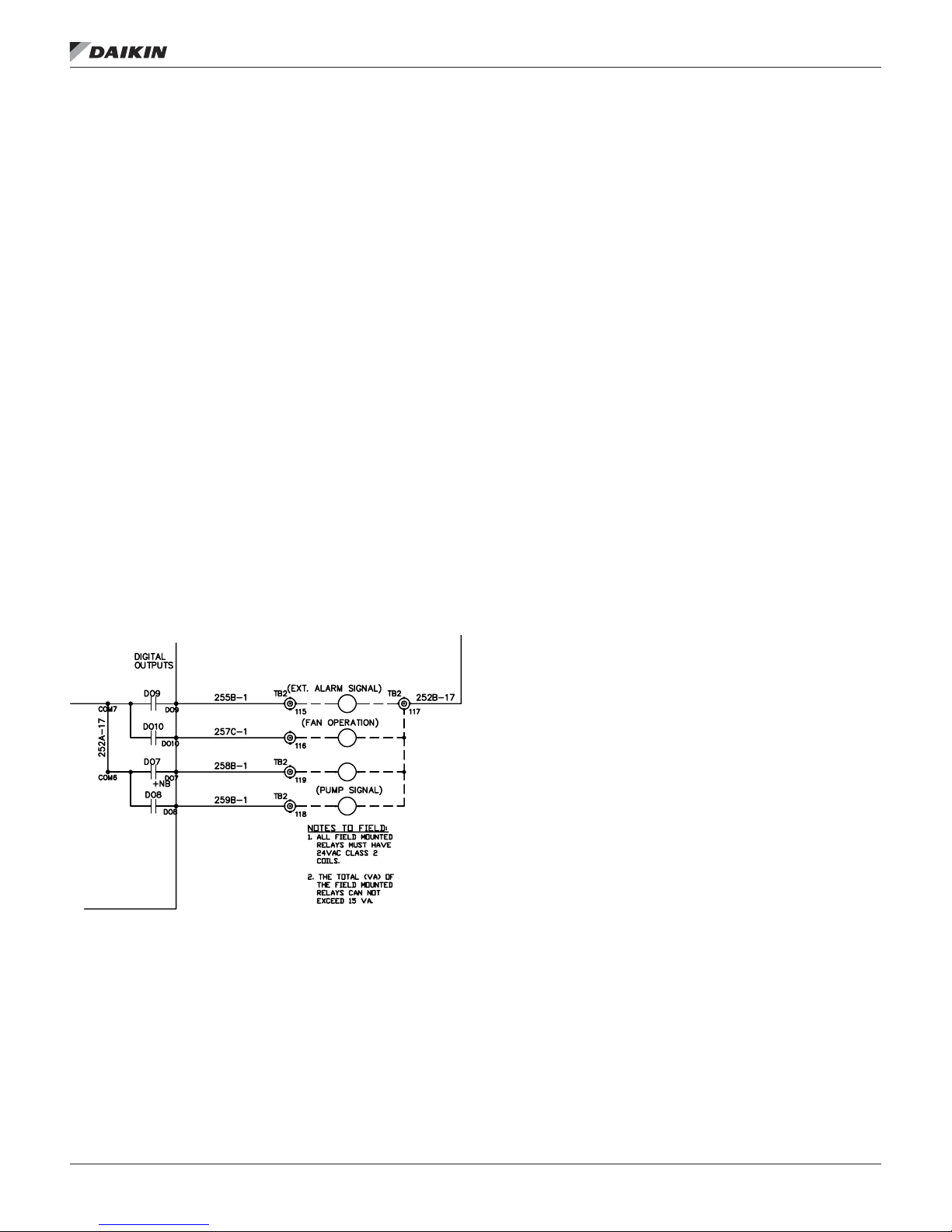
The Remote Alarm Output (MCB-DO9) supplies 24 VAC to
terminal 115 on the eld terminal block (TB2) when the output
is on. To use this signal, wire the coil of a eld supplied and
installed 24 VAC pilot relay across terminals 115 and 117 on
TB2. When this output is on, 24 VAC is supplied from the
control transformer through the output relay to energize the
eld relay. Refer to the as-built wiring diagrams.
The digital alarm output indicates the alarm group that contains
the highest priority active alarm. This output (MCB-DO9) is On
when no alarms are active. The options for the action of this
output when an alarm in a group occurs are On, Fast Blink,
Slow Blink, or Off. These can be edited via the Alarm Out
Cong menu in the Extended menus on keypad/display. The
default values for the three groups of alarms are:
Warnings - Off
Problems - Slow Blink
Faults - Fast Blink
A user could eliminate any signal of a particular group of
alarms through this output by selecting On for that alarm group
in the keypad/display.
VAV Box Signal/Fan Operation Signal
The VAV Box Signal/Fan Operation signal affects how Digital
Output #10 operates. The output is either a supply fan
operation indication or a VAV box signal depending on how
this parameter is set. Digital output #10 is wired to a set of
terminals for eld use.
Fan Operation
The Fan Operation Output (MCB-DO10) supplies 24 VAC to
terminal 116 on the eld terminal block (TB2) when the output
is on. To use this signal, wire the coil of a eld supplied and
installed 24 VAC pilot relay across terminals 116 and 117 on
TB2. When this output is on, 24 VAC is supplied from the
control transformer through the output relay to energize the
eld relay. Refer to the as-built wiring diagrams.
The Fan Operation output is on when the unit is not Off and
when both the unit is Off and airow is detected. It is off when
the unit is off and airow is not detected.
fIeld wIrIng
VAV Output
In the Heating state, the VAV Output is turned off to indicate
that hot air instead of the normal cool air is being supplied to
the VAV boxes. The VAV boxes are driven to their Heating
Position when hot air is provided based on either the normally
open or normally closed contacts of the VAV output. The VFD
will continue to be controlled to maintain the desired duct static
pressure. This output is also off when the unit is in the Startup
or Recirculation states. If this output is in the Heat (off) position
when the unit enters the Fan Only state or Minimum DAT
Control state, the output remains off for an adjustable Post
Heat Time. When the Unit State is Off, the VAV Box Output
is in the Cool (on) position unless airow is detected. When
airow is detected, it switches to the Heat (off) position.
Cooling Only Units
For cooling only VAV systems, the VAV Box Output can
override zone thermostat control and drive the VAV boxes fully
open to facilitate air circulation during the Recirc operating
state. During this time, the VAV Box Output is in the OFF
(or heat) position (eld-installed pilot relay de-energized).
VAV units have a “post heat” control feature that forces the
VFD speed to a minimum before turning on the VAV Box
Output when the Recirc operating state is complete. Post
heat operation prevents excessive duct static pressure that
could otherwise occur when the zone thermostats regain VAV
box control. The setting of a “post heat” timer determines the
duration of post heat operation. This timer is set to zero at the
factory and must be set to a non-zero value to enable the “post
heat” function.
Units with Modulating Heat
The VAV Box Output should be used to switch the VAV boxes
between heating and cooling control. While the unit is in
Startup, Recirc, or Heating operating state (UnocHtg, MWU, or
Heating), the VAV Box Output is in the OFF (or heat) position
(eld-installed pilot relay de-energized) switching the VAV
boxes into heating operation.
VAV units have a “post heat” control feature that forces the
VFD speed to a minimum before closing the VAV Box Output
when the unit leaves the Recirc or Heating operating state.
“Post heat” operation prevents excessive duct static pressure
that could otherwise occur when the zone thermostats regain
VAV box control. When the unit is not in Startup, Recirc, or
Heating operating state, the VAV Box Output is in the ON (or
cool) position (eld-supplied pilot relay energized) switching the
boxes to cooling control.
IM 919-3 • MICROTECH III CONTROLLER 24 www.DaikinApplied.com
fIeld wIrIng
Staged Cooling Outputs
Rooftop air handlers can be ordered with factory-installed
evaporator coils and the capability to control up to eight stages
of eld-supplied cooling equipment. The MicroTech III outputs
designated for these applications are DO 1-4 and DO 7,8 on
the MCB and DO 1,2 on Expansion board A. These outputs
are wired to terminal block TB4 in the main control panel for
connection to the eld supplied condensing unit. Refer to the
as-built wiring schematics for the unit
Outdoor Damper
When applicable the Outdoor Damper Output supplies 24
VAC to terminal 119 on the eld terminal block (TB2) when the
output is on. To use this signal, wire the coil of a eld supplied
and installed 24 VAC pilot relay across terminals 119 and 117
on TB2. When this output is on, 24 VAC is supplied from the
T3 control transformer through the output relay to energize the
eld relay. Refer to the as-built wiring diagrams.
Pump Signal
When applicable the Pump Signal Output supplies 24 VAC to
terminal 113 on the eld terminal block (TB2) when the output
is on. To use this signal, wire the coil of a eld supplied and
installed 24 VAC pilot relay across terminals 113 and 117 on
TB2. When this output is on, 24 VAC is supplied from the T3
control transformer through the output relay to energize the
eld relay. Refer to the as-built wiring diagrams.
Figure 18: Fan Operation Output Wiring Diagram
Field Analog Input Signals
The following inputs may be available for eld connections to a
suitable device.
NOTE: The eld needs to be careful not to ground their
transformer for a eld signal to chassis ground. They
need to use the same ground as the controller to
prevent a voltage potential above 3V. This voltage
potential can damage the Microtech III Controller.
Zone Temperature Sensor Packages
A zone temperature sensor (ZNT1) is optional for all units
except for the 100% outdoor air
Zone Control unit in which case one is required. In all unit
congurations, however, a zone temperature sensor is required
to take advantage of any of the following standard controller
features:
• Unoccupied heating or cooling
• Pre-occupancy purge
• Discharge air reset based on space temperature (DAC
units only)
• Remote timed tenant override
• Remote set point adjustment (CAV-ZTC units only)
A Zone Setpoint Source (Apply Tstat change =No/Yes)
parameter is provided on the keypad/display to allow for
setting the setpoint via the zone thermostat input. The menu is
located in the Heating/Cooling Changeover Setup menu of the
Commission Unit section. When Apply Tstat change is set to
No, the Occupied Cooling Setpoint and the Occupied Heating
Setpoint may be set through the keypad or via a network signal
(all units). In this case these setpoints are changed whenever
the network or keypad value changes.
When Apply Tstat change is set to Yes these setpoints can
only be adjusted through the zone thermostat. This option is
available for all control types (Zone, DAT, and Single zone
VAV). Heating and cooling setpoints must not overlap. The
Occupied Heating Setpoint must be equal to or less than the
Occupied Cooling Setpoint. If a conict occurs from values
entered via the keypad or network, Occupied Heating Setpoint
is automatically adjusted down to eliminate the conict.
When Apply Tstat change =No, the Occupied Heating and
Cooling setpoints may be changed manually by changing the
setpoint displayed on the keypad.
When Apply Tstat change =Yes, the Occupied Cooling Setpoint
is set through a setpoint adjustment included with a wall
mounted space sensor. When the Occupied Cooling Setpoint is
changed by more than 0.5 degrees through the wall mounted
sensor, the Occupied Heating Setpoint is raised or lowered the
same amount so that the difference between the Cooling and
Heating setpoints does not change.
The dead band between the Occupied Cooling Setpoint and
the Occupied Heating Setpoints can be set by setting the Apply
Tstat change to No, setting the differential via the keypad and
resetting the Apply Tstat change back to Yes. The setpoint
adjustment is a resistance value that varies from 5000 ohm to
15000 ohms.
www.DaikinApplied.com 25 IM 919-3 • MICROTECH III CONTROLLER
 Loading...