

Daikin SM-12-012 Service Manual
SM-12-012
Air Conditioners
Service Manual
Sp li t I nv e rt er
Service Manual SM-Inverter_(i)
1.0 Introduction
Inverter Air conditioning technology is today’s solution for superior comfort, higher efficiency and better energy
saving. This Service Manual will intro Daikin Inverter Residential and Light Commercial product.
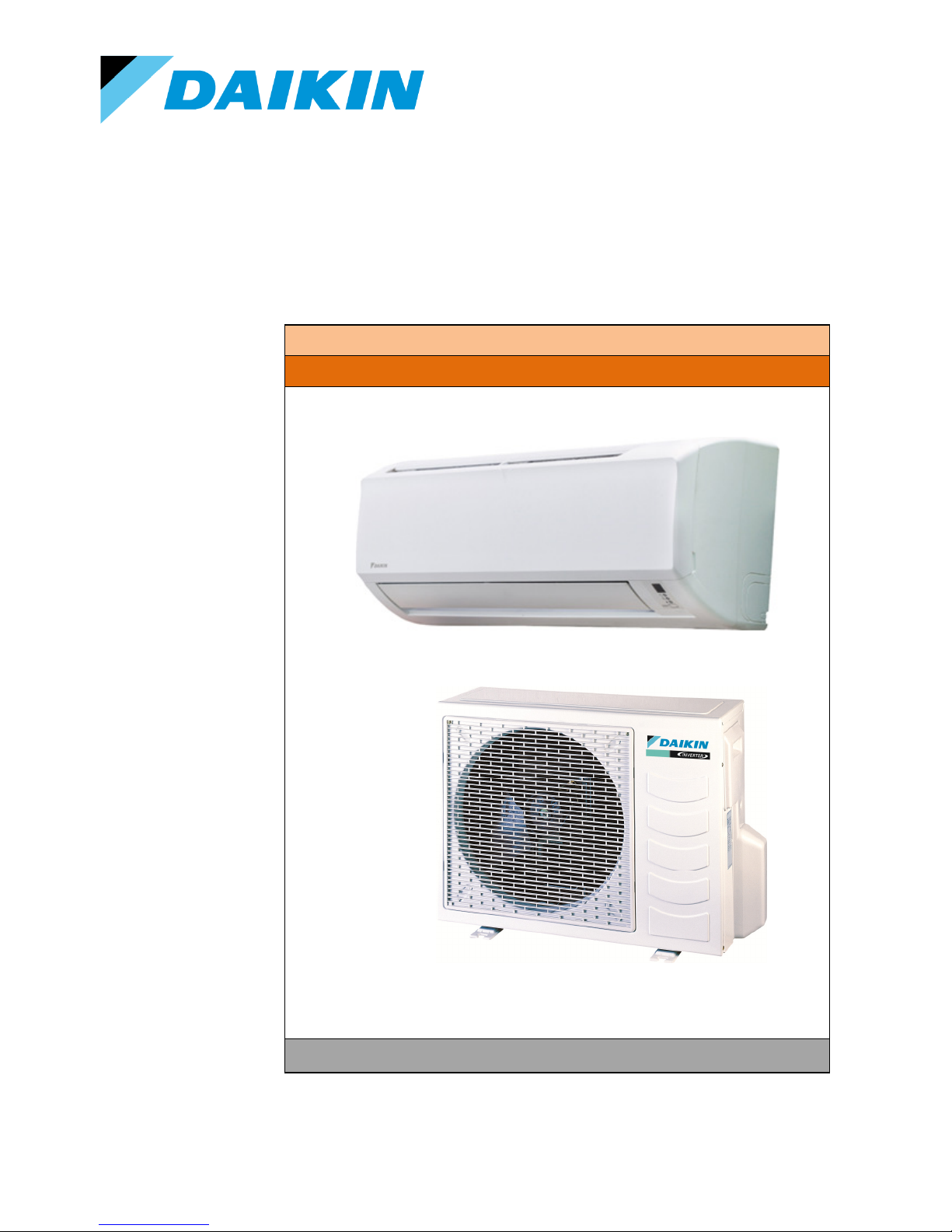
INVERTER Y Series Single Split (Residential, Light Commercial)
i) INDOORS
ii) OUTDOORS
1.1 INVERTER SINGLE SPLIT
Residential (ATXN/FTXN-LV/FTXN-LV1B9 & ARXN/RXN-LV/RXN-LV1B9):
- High Quality & Efficiency Daikin DC Inverter compressor
- High Performance Daikin Inverter Controller
- 5-speed Step-less Fan operation
- New Inverter-only Remote Control
Piping Length & Elevation
Model
Max. total
piping
length
(m)
Max. height
difference
(m)
Pre-charge
for up to
piping length
(m)
ARXN/RXN25LV1B(9) 20 10 7.5 20
ARXN/RXN30LV1B(9) 20 10 7.5 20
ARXN/RXN50LV1B(9) 30 10 7.5 20
ARXN/RXN60LV1B(9) 30 10 7.5 20
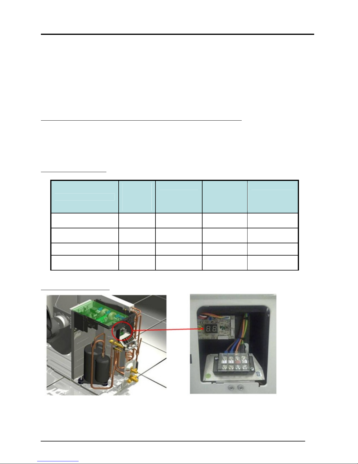
Terminal Block for outdoor:
Additional
charge
(g/m)
- Equipped with 7-segment display to improve serviceability. (Excluded for ARXN/ RXN25/30LV1B(9))
- To retrieve error code & running parameters.
Service Manual SM-Inverter_(i) 2
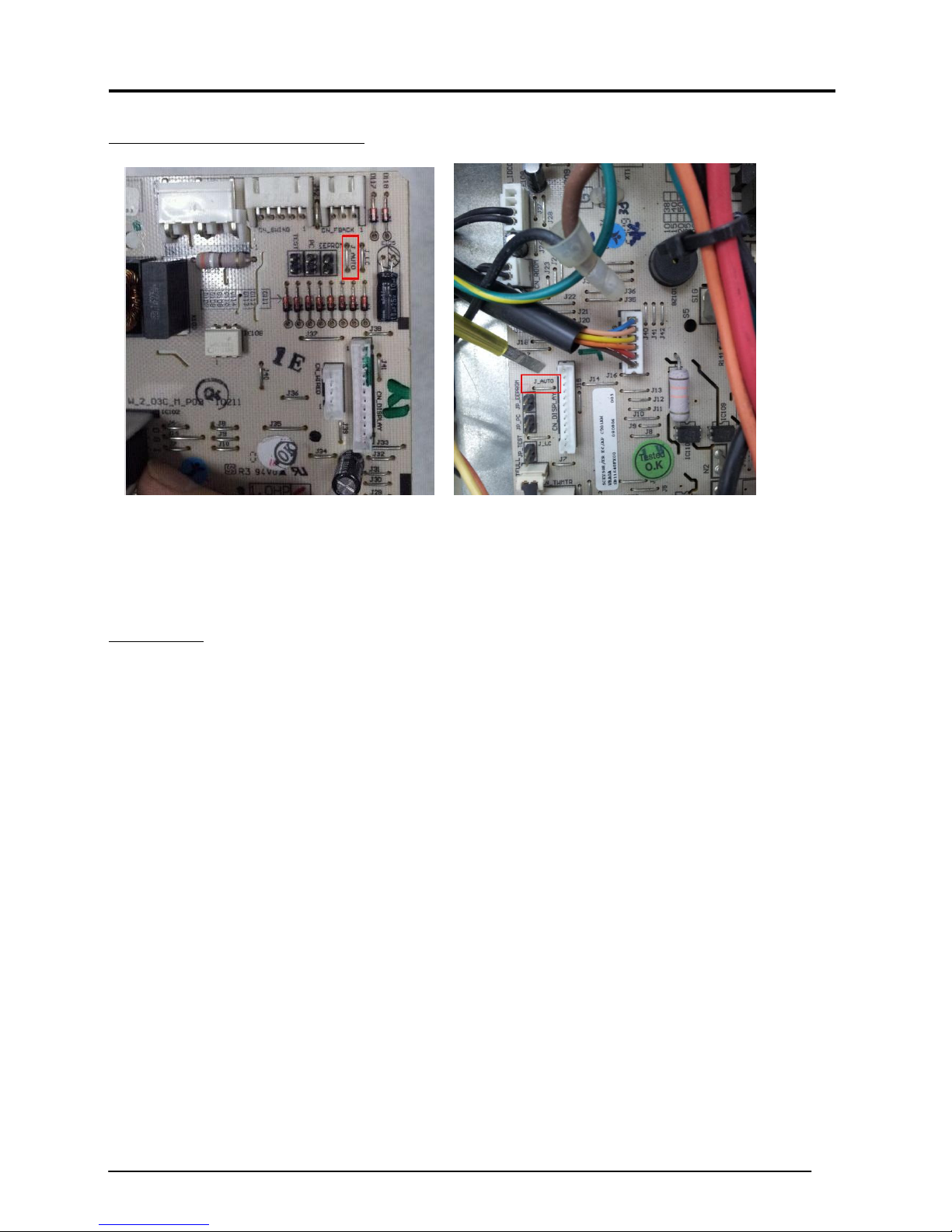
Disable Auto Random Restart function:
Series I Series II
To disable the auto random restart function, kindly cut off the jumper J_AUTO as highlighted in attachment.
Please be informed that after disable auto random restart, unit is not able to restart with last state memory after
power resume from failure. Unit will revert to default setting as below:
Default setting
Unit: Off
Temperature: 24°C
Fan speed: High
Mode: Cooling
Service Manual SM-Inverter_(i) 3

2.0 Algorithm and Control
INDOOR BASIC FUNCTIONS
Residential and Light Commercial
- The system has 5 operating modes. The mode selection is done from indoor using handset.
- The operating modes are:
• Cool
• Heat
• Fan
• Auto
• Dry
Cool Mode:
- When Tr ≥ Ts - 1.5°C
•
Comp, Indoor Fan and Outdoor Fan ON.
- When Tr ≤ Ts - 2°C
•
Compressor and Outdoor Fan OFF.
Tr = Room Temperature
Ts = Set Temperature
When cooling load is too small and the room temperature still falling below compressor cut off point,
compressor will stop.
Service Manual SM-Inverter_(i) 4
Heat Mode:
- When Ts > Tr - 1.0°C
• Comp, ID Fan and OD Fan ON.
- When Tr ≥ Ts + 1.5°C
• Compressor and Outdoor Fan OFF.
• Indoor Fan off if indoor coil ≤ 20°C.
Tr = Room Temperature
Ts = Set Temperature
When heating load is too small, and the room temperature still rising above compressor cut off point, compressor
will stop.
FAN MODE
- Only High, Medium and Low fan speeds are allowed.
- When changing cool mode to fan mode, the compressor will stop and OD fan stops based on fan OFF
control.
- Compressor only ON if the minimum stop time is > 3 minutes and the user change back to cool mode.
- Fan speed will maintain same as during fan mode.
AUTO MODE
- For heat pump only
- Mode switching point:
• Heating Cooling
Tr ≥ Ts + 2.5
• Cooling Heating
Tr ≤ Ts – 2.5
- During initial operation
• Cooling operation: Tr > Ts
Service Manual SM-Inverter_(i) 5

• Heating operation: Tr < Ts
ID-OD COMMUNICATION
- Master by outdoor unit.
- Indoor controller board will transmit signal to outdoor controller board every 0.5s. Outdoor unit will
response to indoor once the valid data is received.
- If the data communication line between indoor and outdoor disrupted for 15s continuously, compressor
will stop, OD fan stop with fan OFF timer. ID LED blinks error.
- If the communication resumes within 15s, error code is clear and compressor restarts after 3 minutes.
- If the communication does not resume after 15s, unit unable to restart and the error keep blinking.
Service Manual SM-Inverter_(i) 6
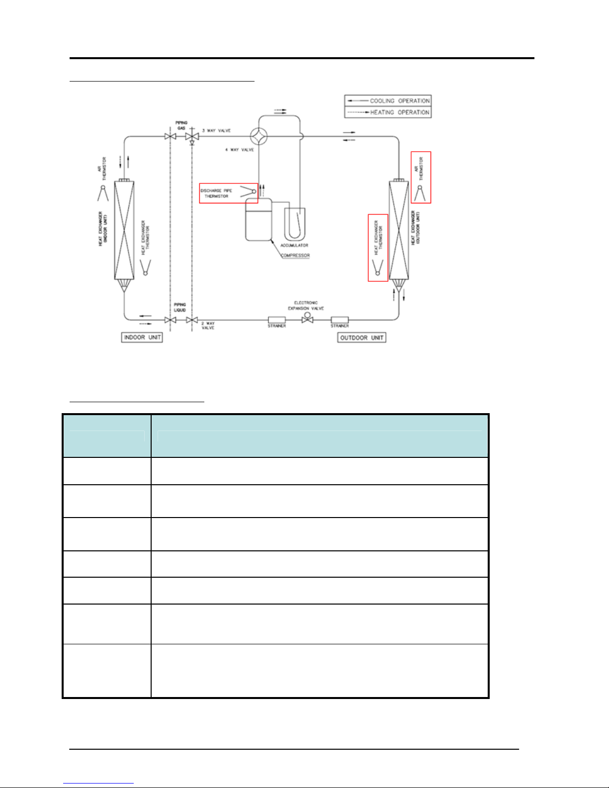
THERMISTORS IN ARXN/ RXN-LV1B(9)
FUNCTIONS OF THERMISTOR
Thermistor
Discharge pipe
Outdoor coil
Outdoor air
Functions
Used for discharge superheat (SH) & EXV control.
Used for defrost control. Also used for inverter current protection control in
Series II.
Used for defrost & outdoor fan speed control. Also used for PMV, overall
current protection & preheating operation control.
Heat sink Used for capturing heat sink temperature.
Suction pipe Used for EXV (SH) & suction pipe SH protection control in heating.
Gas pipe Used for gas pipe isothermal control in cooling. EXV opening is controlled so
that accurate cooling capacity is achieved in each room.
Liquid pipe Used for sub-cooling control in heating. Actual sub-cooling will be calculated
with liquid pipe & max. heat exchanger temperature among all rooms. EXV
opening is then adjusted to reach the target sub-cooling.
Service Manual SM-Inverter_(i) 7
MINIMUM RUN CONTROL
To prevent frequent compressor ON/OFF & to allow pressure equalization
• The compressor will be on 3 minutes stand-by after turning OFF before it is allowed to turn ON.
• OD fan OFF delay to improve pressure equalization & to prevent refrigerant from entering into
evaporator.
AUTO RESTART
- Factory pre-set.
- Allow unit to automatically resume the same operating mode it was in before a power failure.
4-WAY VALVE CONTROL
- Change over switching is only carried out during operation.
- OFF delayed is applied when the coil switches from ON to OFF.
Operating mode 4-way valve is
Heat, except for defrost ON
Cool
Dry
Defrost
DEFROST CYCLE
During defrost
Compressor ON
4-way valve OFF
EXV in operation room Fixed opening
EXV in operation stop room -
Outdoor fan OFF
OFF
RXN-LV(1B/1B9)
Indoor fan OFF
Service Manual SM-Inverter_(i) 8

ATXN/FTXN-LV and ARXN/RXN-LV(1B/1B9):
DEFROST CONTROL
- Condition for entering defrost
• Compressor minimum run time – 6 minutes OR
• Compressor accumulated run time of 45 minutes if Outdoor coil < 3°C.
- Condition for terminating defrost
• OD coil > 12°C or
• Total defrost timer of 650 seconds.
OUTDOOR FAN CONTROL
- Determine from
• Compressor target rotation: higher fan speed with higher rotation.
• Outdoor air temperature.
- Cool mode: Higher fan speed with higher outdoor air temperature.
- Heat mode: Higher fan speed with lower outdoor air temperature.
- When compressor stops, fan OFF delay 30 seconds is carried out
INDOOR COIL FREEZE PREVENTION
- Only available in cooling mode.
- When the indoor coil temperature < 2°C, the compressor starts to drop the frequency.
- This protection will cut in when:
• Indoor coil temperature < 0°C for more than 180s. Compressor will stop, OD fan stop after 30s
and indoor fan can only run at lowest fan speed.
- The unit can only be restarted after 3 minutes.
- When the indoor coil temperature > 13°C, the compressor frequency will be reset based on the OD
ambient, room and set temperature.
Service Manual SM-Inverter_(i) 9
Target Rotation
Command Rotation
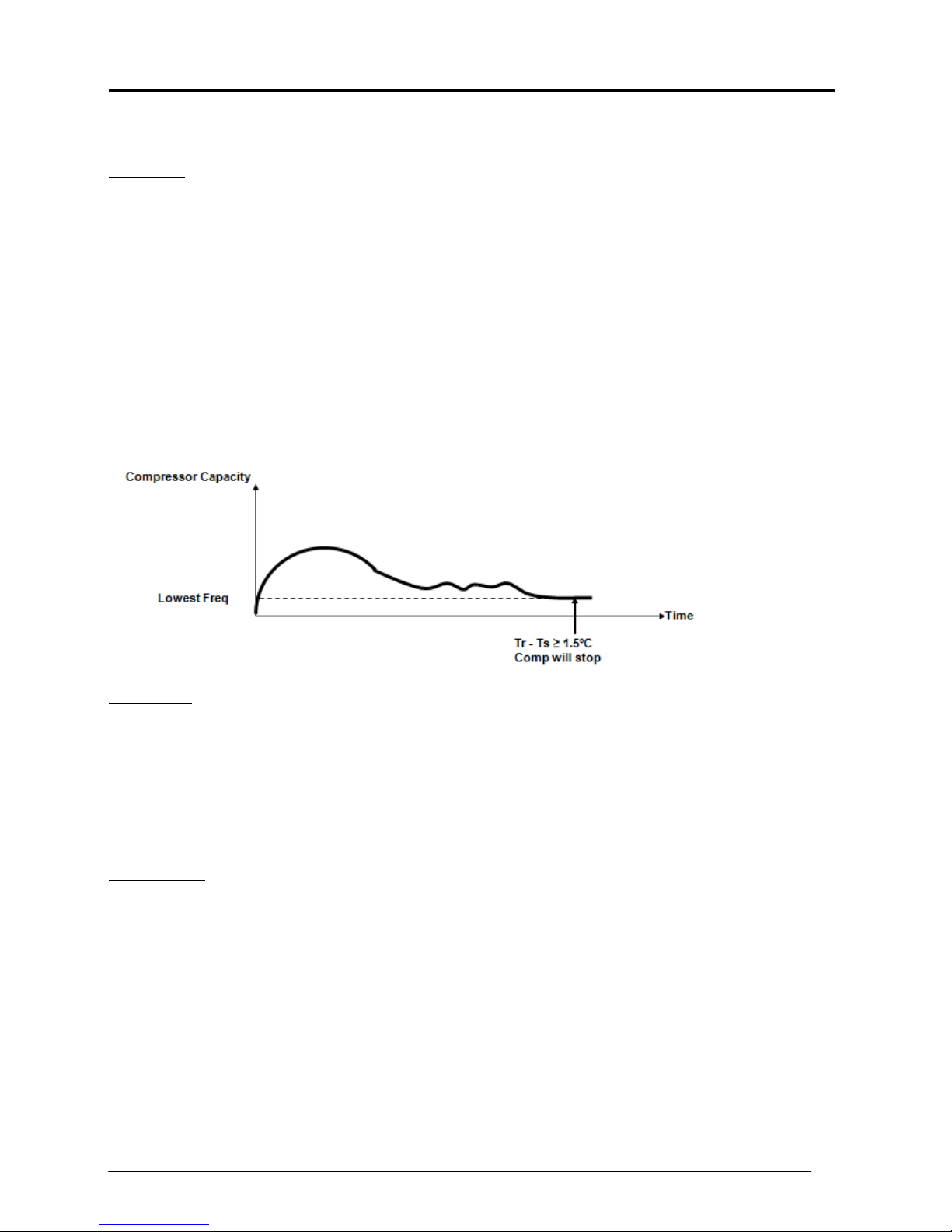
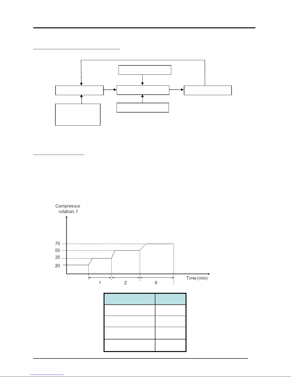
ROTATION REGULATING FUNCTIONS
Starting Rotation
∆
T
Defrost*
* Defrost control for heat pump model only
STARTING ROTATION
STARTING CONTROL
- To avoid excessive oil discharge from compressor or to promote oil lubrication during startup.
- To prevent liquid flood back to the compressor.
- To limit starting current.
- When compressor starts to rotate from OFF to ON, compressor rotation is set to run gradually to each
upper limit at a specific timer setting.
Upper limit rotation
Limit Rotation
Lower limit rotation
Service Manual SM-Inverter_(i) 10
Model Max. f
ARXN/RXN25LV1B(9) 68 Hz
ARXN/RXN35LV1B(9) 74 Hz
ARXN/RXN50LV1B(9) 90 Hz
ARXN/RXN60LV1B(9) 93 Hz
∆T
d∆T
∆T = T - T d∆T = ∆T - ∆T
decreased
COMMAND ROTATION
- Cut in upon termination of Starting Control.
- Achieve capacity control by controlling the compressor rotation based on :
• Temperature difference between set and room temperature, ∆T.
• Limit Rotation.
• Defrost control.
Fuzzy Control
- Based on temperature difference, ∆T, current fan speed setting & current indoor operating mode at every
30 seconds interval.
Condition 1
Use to set target for compressor frequency change
Temperature Difference
Condition 2
Compressor frequency is increased or
LIMIT ROTATION
Determine from
• Upper limit rotation
A minimum value was determined among the upper limits rotation, i.e. protection controls.
• Lower limit rotation
A maximum value was determined among the lower limits rotation, i.e. protection controls.
Generally, compressor rotation is controlled within 4 zones: stop, drop, keep, up and reset subjected to a
particular operating temperature/current/pressure.
Service Manual SM-Inverter_(i) 11
Zone Control
Stop
Drop Frequency will be dropped with a timer setting.
Keep Frequency is maintained at lower/upper limit.
Up Frequency will be increased with a timer setting.
Reset Frequency lower/upper limit is canceled and returned to command rotation.
Compressor is stopped when a certain limit reaches the stop zone for abnormality
correction.
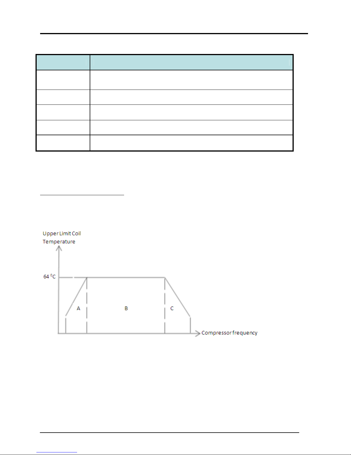
HIGH PRESSURE PROTECTION
- To prevent high pressure in the system.
- Compressor operating frequency is adjusted based on upper limit of coil temperature
- The compressor frequency is adjusted based on coil temperature:
• During cooling mode – outdoor coil temperature.
• During heating mode – indoor coil temperature.
- This protection is activated when the coil temperature > 64°C, the compressor stop and OD fan stop after
30s.
- The unit can only be restarted after 3 minutes.
Service Manual SM-Inverter_(i) 12
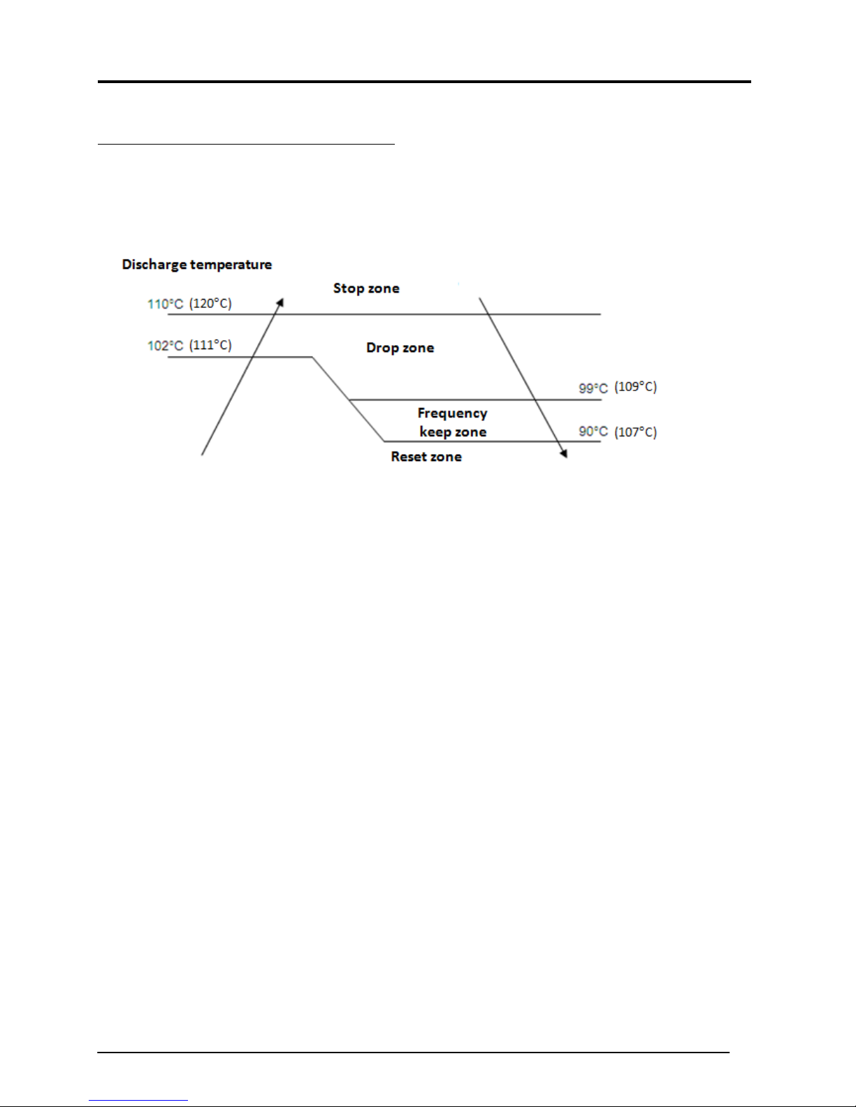
DISCHARGE PIPE TEMPERATURE CONTROL
- Used as a measure of the compressor’s internal temperature.
- Compressor frequency is control to keep this temperature from going up further when it rises above a
certain level.
- If compressor discharge temperature >102°C (111°C) for the first time, this control starts and set the
current frequency as upper limit. At the same time, running frequency start to reduce by 1 step and so on,
until temperature falls between 99°C (109°C)and 90°C (107°C) – at the maintain zone.
- This protection is activated when the compressor discharge temperature > 110°C (120°C). The
compressor will stop and considered trip.
-
- If the compressor discharge temperature < 90°C (107°C), the compressor frequency will be reset based
on the OD ambient, set and room temperature.
Service Manual SM-Inverter_(i) 13
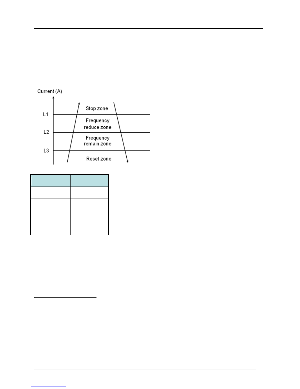
OVERALL CURRENT CONTROL
- To monitor the overall current and to restrict the compressor upper limit rotation in order to prevent
circuit breakers from exceeding the rated capacity.
- Detected during compressor running.
Model L1
ARXN/ RXN25 9.5A
ARXN/ RXN35 10.0A
ARXN/ RXN50 12.0A
ARXN/ RXN60 12.0A
- When the input current for running compressor exceeds L2, running frequency will be reduced by 1 step.
If current still exceeds L2, frequency will be reduced by another 1 step until total current falls between
L2 and L3.
- This protection cut in when the input current exceeds L1 for 2 seconds – (ARXN/RXN LV1B (9))
Compressor will stop and it is considered total current overload.
- If input current <L3, the compressor frequency is reset based on the OD ambient, set and room
temperature.
OIL RECOVERY CONTROL
- When the compressor operates for certain duration at low frequency, the oil level in the compressor may
become low due to incomplete oil return.
- To prevent damage to the compressor or compressor lock due to low oil lever.
- To promote refrigerant flow to carry the oil back to the compressor.
Entering condition:
• Compressor rotation < 35 Hz, at the end of a 20 minutes timer: set lower limit rotation to 35 Hz
& EXV opening is fixed at current opening + 50 pulse. This control is reset when rotation > 35
Hz.
Service Manual SM-Inverter_(i) 14
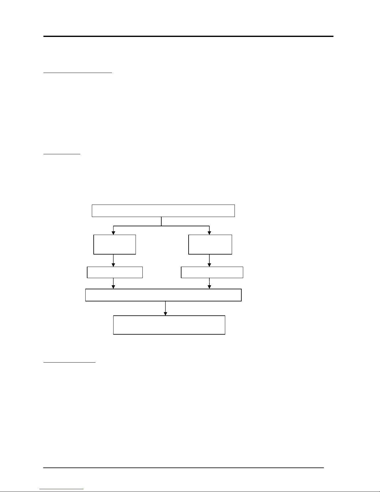
3.0 Service Diagnosis
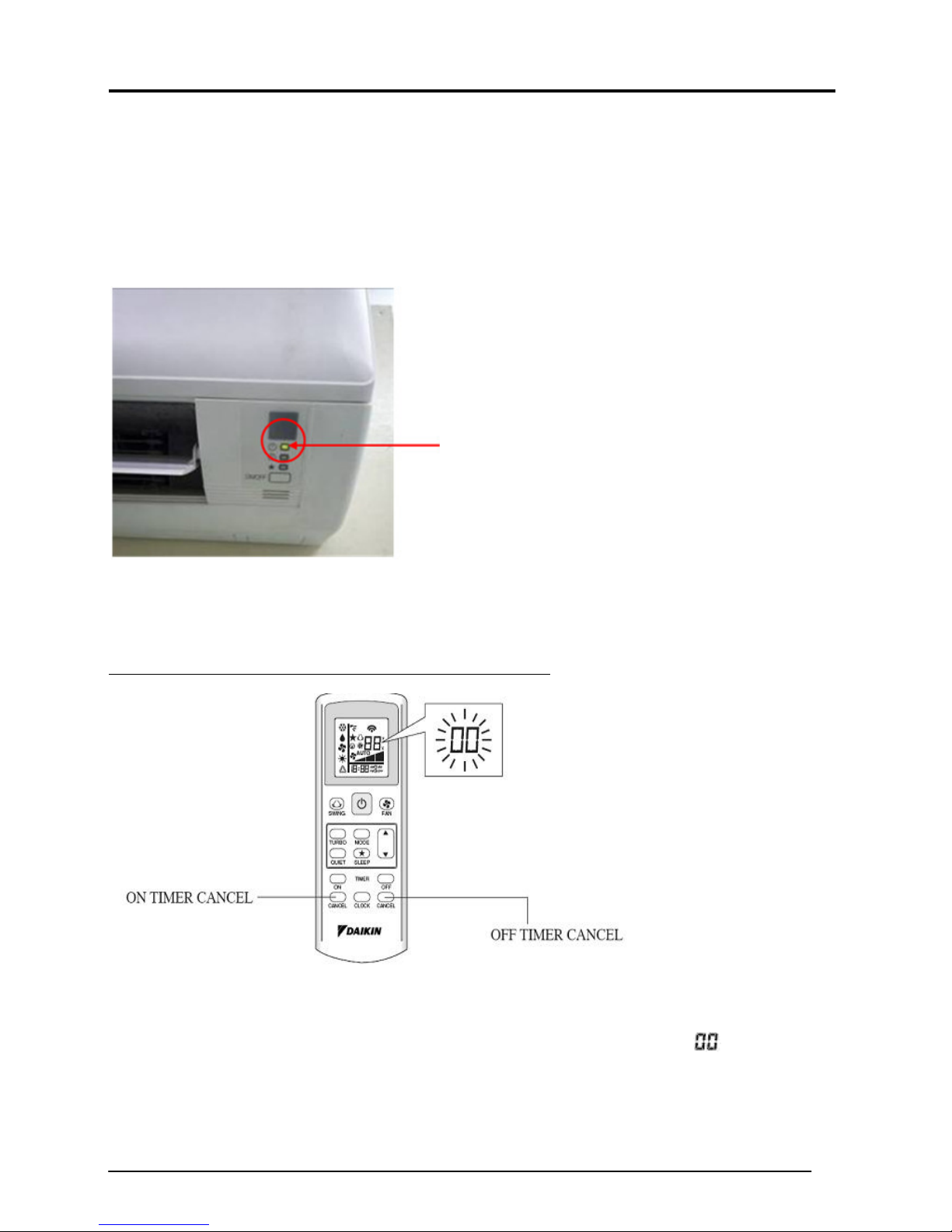
From indoor units
• When any error occurs, indoor LED display will keep blinking – green light:
• The blinking pattern not indicate error details
• The error details have to retrieve from handset in error code form.
LED blinks here
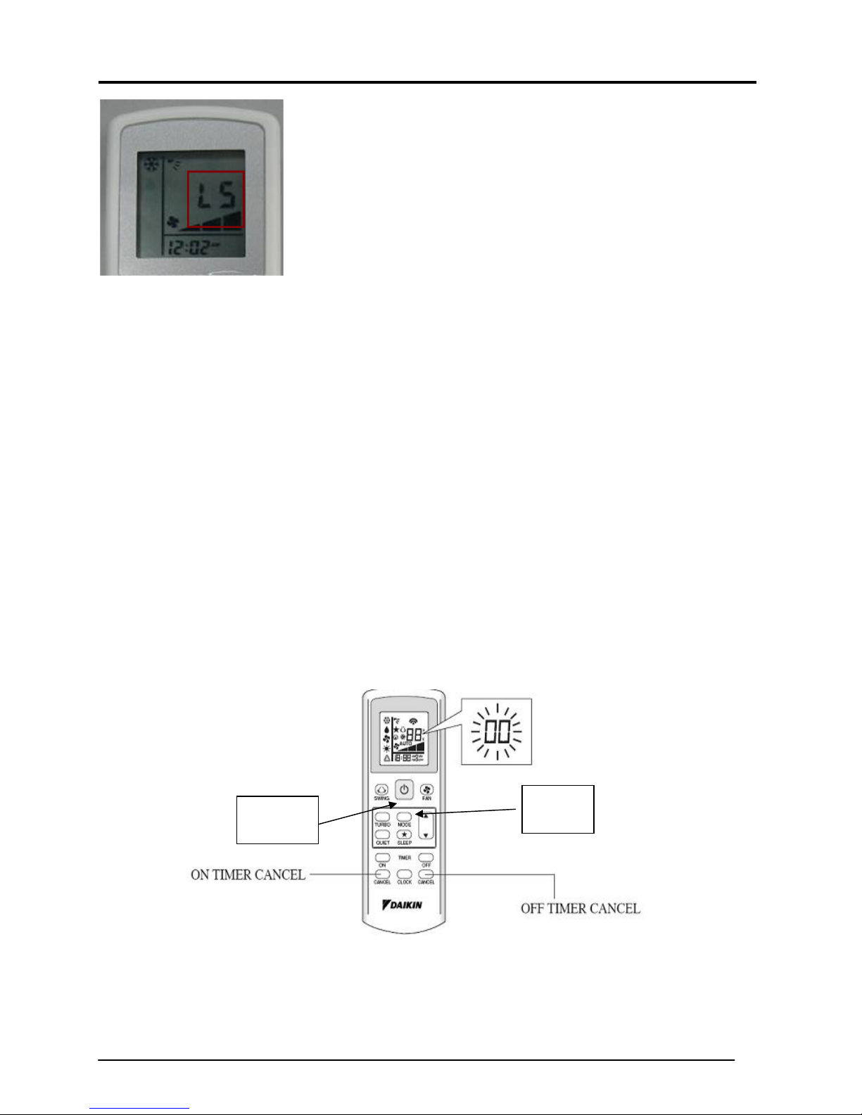
Indoor Wireless Handset: BRC52A61/A62
Using wireless handset BRC52A61/A62 to retrieve error code:
1. Hold down ON TIMER CANCEL or OFF TIMER CANCEL for 5 seconds until “ ” indication
flashes on the handset temperature display section.
2. Then, press the same button repeatedly. A series of error code will appear until ID buzzer produces a
long beep. The corresponding error code is indicated on the handset temperature display section.
Service Manual SM-Inverter_(i) 15
3. ID unit buzzer will produce a long beep if the handset error code matched with unit error.
4. A short and two consecutive beeps is Not the unit error.
5. The code display will cancel itself if the button is not pressed for 1 minute.
How to Retrieved Last State Error:
1) Remove battery from remote controller.
2) Replace battery again into remote controller.
3) Press Mode & ON/OFF buttons together.
4) The “ 00 “ will show at temperature section.
5) Press Mode button to 5:00
6) Press Power On toward the indoor unit. Unit LED blinks two times indicate received signal.
7) ON hold fan button till screen become normal display.
8) Repeat the normal step to retrieve error. (by using remote controller step. Holding TIMER CANCEL…)
9) By using this method, the error shown will be Last State Error.(Previous error in this unit)
ON/OFF
button
Service Manual SM-Inverter_(i) 16
Mode
button
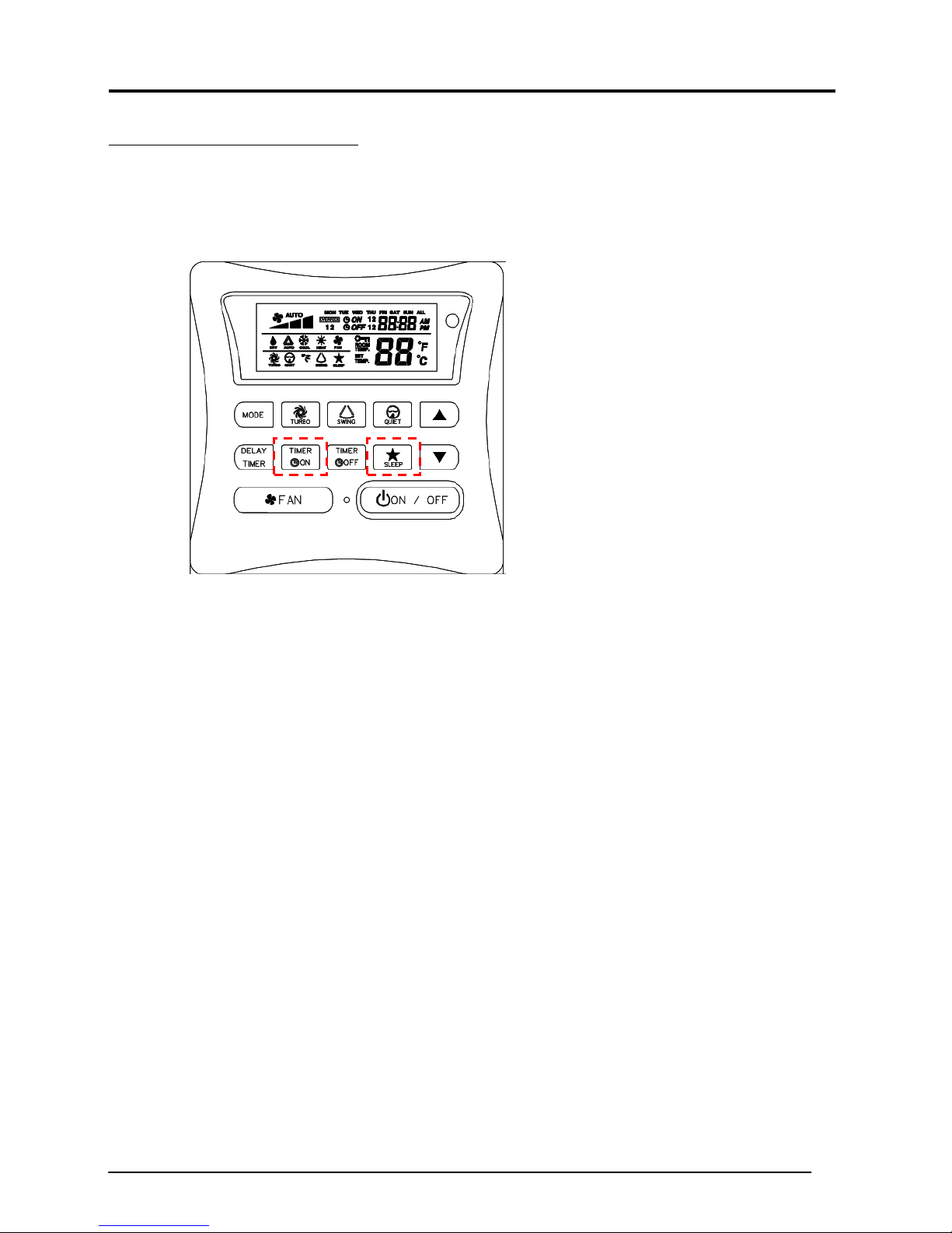
Using wired handset BRC51A61/A62:
- The error will show at the LCD display.
- BRC51A61 can retrieved last state memory by :
- Press SLEEP & TIMER ACTIVE simultaneously for 5 seconds and the error will be flashed.
Service Manual SM-Inverter_(i) 17
 Loading...