

Daikin SEHVX20BAW, SEHVX32BAW, SEHVX40BAW, SEHVX64BAW, SERHQ020BAW1 Operation manuals
...
Installation and operation
manual
Inverter heat pump chilling unit with separate hydro
module
SEHVX20BAW
SEHVX32BAW
SEHVX40BAW
SEHVX64BAW
SERHQ020BAW1
SERHQ032BAW1
Installation and operation manual
Inverter heat pump chilling unit with separate hydro module
English
Directivelor, cu amendamentele respective.
<A>
<B>
<C>
DEKRA (NB0344)
2082543.0551-QUA/EMC
DAIKIN.TCF.025H27/10-2017
Direktive z vsemi spremembami.
Direktiivid koos muudatustega.
Директиви, с техните изменения.
Direktyvose su papildymais.
Direktīvās un to papildinājumos.
Smernice, v platnom znení.
18192021222324
Direktiver, med senere ændringer.
Direktiv, med företagna ändringar.
Direktiver, med foretatte endringer.
10111213141516
Directives, as amended.
Direktiven, gemäß Änderung.
deklaruje na własną i wyłączną odpowiedzialność, że urządzenia, których ta deklaracja dotyczy:
declară pe proprie răspundere că echipamentele la care se referă această declaraţie:
z vso odgovornostjo izjavlja, da je oprema naprav, na katero se izjava nanaša:
kinnitab oma täielikul vastutusel, et käesoleva deklaratsiooni alla kuuluv varustus:
декларира на своя отговорност, че оборудването, за коeто се отнася тази декларация:
visiška savo atsakomybe skelbia, kad įranga, kuriai taikoma ši deklaracija:
ar pilnu atbildību apliecina, ka tālāk aprakstītās iekārtas, uz kurām attiecas šī deklarācija:
vyhlasuje na vlastnú zodpovednosť, že zariadenie, na ktoré sa vzťahuje toto vyhlásenie:
tamamen kendi sorumluluǧunda olmak üzere bu bildirinin ilgili olduǧu donanımının aşaǧıdaki gibi olduǧunu beyan eder:
17
18
19
20
21
22
23
24
25
megfelelnek az alábbi szabvány(ok)nak vagy egyéb irányadó dokumentum(ok)nak, ha azokat előírás szerint használják:
spełniają wymogi następujących norm i innych dokumentów normalizacyjnych, pod warunkiem że używane są zgodnie z naszymi instrukcjami:
sunt în conformitate cu următorul (următoarele) standard(e) sau alt(e) document(e) normativ(e), cu condiţia ca acestea să fie utilizate în conformitate cu
instrucţiunile noastre:
skladni z naslednjimi standardi in drugimi normativi, pod pogojem, da se uporabljajo v skladu z našimi navodili:
on vastavuses järgmis(t)e standardi(te)ga või teiste normatiivsete dokumentidega, kui neid kasutatakse vastavalt meie juhenditele:
съответстват на следните стандарти или други нормативни документи, при условие, че се използват съгласно нашите инструкции:
atitinka žemiau nurodytus standartus ir (arba) kitus norminius dokumentus su sąlyga, kad yra naudojami pagal mūsų nurodymus:
tad, ja lietoti atbilstoši ražotāja norādījumiem, atbilst sekojošiem standartiem un citiem normatīviem dokumentiem:
sú v zhode s nasledovnou(ými) normou(ami) alebo iným(i) normatívnym(i) dokumentom(ami), za predpokladu, že sa používajú v súlade snašim
návodom:
161718192021222324
ürünün, talimatlarımıza göre kullanılması koşuluyla aşağıdaki standartlar ve norm belirten belgelerle uyumludur:
25
Directives, telles que modifiées.
010203040506070809
Değiştirilmiş halleriyle Yönetmelikler.
25
Direktiivejä, sellaisina kuin ne ovat muutettuina.
v platném znění.
Smjernice, kako je izmijenjeno.
irányelv(ek) és módosításaik rendelkezéseit.
z późniejszymi poprawkami.
17
Richtlijnen, zoals geamendeerd.
Directivas, según lo enmendado.
Direttive, come da modifica.
Οδηγιών, όπως έχουν τροποποιηθεί.
Directivas, conforme alteração em.
*
**
както е изложено в <A> и оценено положително от <B>
съгласно Сертификата<C>.
kaip nustatyta <A> ir kaip teigiamai nuspręsta <B> pagal
Sertifikatą<C>.
kā norādīts <A> un atbilstoši <B> pozitīvajam vērtējumam
saskaņā ar sertifikātu<C>.
ako bolo uvedené v <A> a pozitívne zistené <B> vsúlade
s osvedčením<C>.
<A>’da belirtildiği gibi ve <C>Sertifikasına göre <B>
tarafından olumlu olarak değerlendirildiği gibi.
Директив со всеми поправками.
21Забележка*
22Pastaba*
23Piezīmes*
24Poznámka*
25Not*
Daikin Europe N.V. je pooblaščen za sestavo datoteke s tehnično mapo.
Daikin Europe N.V. on volitatud koostama tehnilist dokumentatsiooni.
Daikin Europe N.V. е оторизирана да състави Акта за техническа конструкция.
Daikin Europe N.V. yra įgaliota sudaryti šį techninės konstrukcijos failą.
Daikin Europe N.V. ir autorizēts sastādīt tehnisko dokumentāciju.
Spoločnosť Daikin Europe N.V. je oprávnená vytvoriť súbor technickej konštrukcie.
Daikin Europe N.V. Teknik Yapı Dosyasını derlemeye yetkilidir.
19**
20**
21**
22**
23**
24**
25**
a(z) <A> alapján, a(z) <B> igazolta a megfelelést, a(z)
<C>tanúsítvány szerint.
zgodnie z dokumentacją <A>, pozytywną
opinią <B> i Świadectwem<C>.
aşa cum este stabilit în <A> şi apreciat pozitiv de<B>
în conformitate cu Certificatul<C>.
kot je določeno v <A> in odobreno s strani <B>
vskladu scertifikatom<C>.
nagu on näidatud dokumendis <A> ja heaks kiidetud
<B> järgi vastavalt sertifikaadile<C>.
16Megjegyzés*
17Uwaga*
18Notă*
19Opomba*
20Märkus*
Machinery 2006/42/EC
enligt <A> och godkänts av <B> enligt
Certifikatet<C>.
som det fremkommer i <A> og gjennom positiv
bedømmelse av <B> ifølge Sertifikat<C>.
jotka on esitetty asiakirjassa <A> ja jotka <B>
on hyväksynyt Sertifikaatin<C> mukaisesti.
jak bylo uvedeno v <A> a pozitivně zjištěno
<B> vsouladu sosvědčením<C>.
kako je izloženo u <A> i pozitivno ocijenjeno odstrane
Electromagnetic Compatibility 2014/30/EU
заявляет, исключительно под свою ответственность, что оборудование, к которому относится настоящее заявление:
erklærer under eneansvarlig, at udstyret, som er omfattet af denne erklæring:
deklarerar i egenskap av huvudansvarig, att utrustningen som berörs av denna deklaration innebär att:
erklærer et fullstendig ansvar for at det utstyr som berøres av denne deklarasjon innebærer at:
ilmoittaa yksinomaan omalla vastuullaan, että tämän ilmoituksen tarkoittamat laitteet:
prohlašuje ve své plné odpovědnosti, že zařízení, k němuž se toto prohlášení vztahuje:
izjavljuje pod isključivo vlastitom odgovornošću da oprema na koju se ova izjava odnosi:
teljes felelőssége tudatában kijelenti, hogy a berendezések, melyekre e nyilatkozat vonatkozik:
09
10
11
12
13
14
15
16
estão em conformidade com a(s) seguinte(s) norma(s) ou outro(s) documento(s) normativo(s), desde que estes sejam utilizados de
acordo com as nossas instruções:
соответствуют следующим стандартам или другим нормативным документам, при условии их использования согласно нашим инструкциям:
overholder følgende standard(er) eller andet/andre retningsgivende dokument(er), forudsat at disse anvendes i henhold til vore instrukser:
respektive utrustning är utförd i överensstämmelse med och följer följande standard(er) eller andra normgivande dokument, under förutsättning att
användning sker i överensstämmelse med våra instruktioner:
respektive utstyr er i overensstemmelse med følgende standard(er) eller andre normgivende dokument(er), under forutssetning av at disse brukes i
henhold til våre instrukser:
vastaavat seuraavien standardien ja muiden ohjeellisten dokumenttien vaatimuksia edellyttäen, että niitä käytetään ohjeidemme mukaisesti:
za předpokladu, že jsou využívány v souladu s našimi pokyny, odpovídají následujícím normám nebo normativním dokumentům:
08091011121314
u skladu sa slijedećim standardom(ima) ili drugim normativnim dokumentom(ima), uz uvjet da se oni koriste u skladu s našim uputama:
15
ob upoštevanju določb:
vastavalt nõuetele:
следвайки клаузите на:
laikantis nuostatų, pateikiamų:
ievērojot prasības, kas noteiktas:
19202122232425
održiavajúc ustanovenia:
11Information*
12Merk*
13Huom*
bunun koşullarına uygun olarak:
delineato nel <A> e giudicato positivamente da<B>
secondo il Certificato<C>.
όπως καθορίζεται στο <A> και κρίνεται θετικά
από το <B> σύμφωνα με το Πιστοποιητικό<C>.
tal como estabelecido em <A> e com o parecer positivo
<B> prema Certifikatu<C>.
14Poznámka*
15Napomena*
de <B> de acordo com o Certificado<C>.
как указано в <A> и в соответствии сположительным
решением <B> согласно Свидетельству<C>.
som anført i <A> og positivt vurderet af <B> ihenhold til
Certifikat<C>.
Daikin Europe N.V. on valtuutettu laatimaan Teknisen asiakirjan.
Společnost Daikin Europe N.V. má oprávnění ke kompilaci souboru technické konstrukce.
Daikin Europe N.V. je ovlašten za izradu Datoteke o tehničkoj konstrukciji.
A Daikin Europe N.V. jogosult a műszaki konstrukciós dokumentáció összeállítására.
Daikin Europe N.V. ma upoważnienie do zbierania i opracowywania dokumentacji konstrukcyjnej.
Daikin Europe N.V. este autorizat să compileze Dosarul tehnic de construcţie.
13**
14**
15**
16**
17**
18**
Shigeki Morita
Director
Ostend, 1st of December 2017
Η Daikin Europe N.V. είναι εξουσιοδοτημένη να συντάξει τον Τεχνικό φάκελο κατασκευής.
A Daikin Europe N.V. está autorizada a compilar a documentação técnica de fabrico.
Компания Daikin Europe N.V. уполномочена составить Комплект технической документации.
Daikin Europe N.V. er autoriseret til at udarbejde de tekniske konstruktionsdata.
Daikin Europe N.V. är bemyndigade att sammanställa den tekniska konstruktionsfilen.
Daikin Europe N.V. har tillatelse til å kompilere den Tekniske konstruksjonsfilen.
07**
08**
09**
10**
11**
12**
declares under its sole responsibility that the equipment to which this declaration relates:
erklärt auf seine alleinige Verantwortung daß die Ausrüstung für die diese Erklärung bestimmt ist:
déclare sous sa seule responsabilité que l'équipement visé par la présente déclaration:
CE - DECLARATION-OF-CONFORMITY CE - DECLARACION-DE-CONFORMIDAD CE - DECLARAÇÃO-DE-CONFORMIDADE CE - ERKLÆRING OM-SAMSVAR CE - IZJAVA-O-USKLAĐENOSTI CE - IZJAVA O SKLADNOSTI CE - ATITIKTIES-DEKLARACIJA
CE - KONFORMITÄTSERKLÄRUNG CE - DICHIARAZIONE-DI-CONFORMITA CE - ЗАЯВЛЕНИЕ-О-СООТВЕТСТВИИ CE - ILMOITUS-YHDENMUKAISUUDESTA CE - MEGFELELŐSÉGI-NYILATKOZAT CE - VASTAVUSDEKLARATSIOON CE - ATBILSTĪBAS-DEKLARĀCIJA
CE - DECLARATION-DE-CONFORMITE CE - ΔHΛΩΣΗ ΣΥΜΜΟΡΦΩΣΗΣ CE - OVERENSSTEMMELSESERKLÆRING CE - PROHLÁŠENÍ-O-SHODĚ CE - DEKLARACJA-ZGODNOŚCI CE - ДЕКЛАРАЦИЯ-ЗА-СЪОТВЕТСТВИЕ CE - VYHLÁSENIE-ZHODY
CE - CONFORMITEITSVERKLARING CE - FÖRSÄKRAN-OM-ÖVERENSTÄMMELSE CE - DECLARAŢIE-DE-CONFORMITATE CE - UYGUNLUK-BEYANI
verklaart hierbij op eigen exclusieve verantwoordelijkheid dat de apparatuur waarop deze verklaring betrekking heeft:
Daikin Europe N.V.
01
02
03
04
06Nota*
under iagttagelse af bestemmelserne i:
enligt villkoren i:
gitt i henhold til bestemmelsene i:
noudattaen määräyksiä:
za dodržení ustanovení předpisu:
prema odredbama:
követi a(z):
zgodnie z postanowieniami Dyrektyw:
101112131415161718
declara bajo su única responsabilidad que el equipo al que hace referencia la declaración:
dichiara sotto la propria responsabilità che gli apparecchi a cui è riferita questa dichiarazione:
δηλώνει με αποκλειστική της ευθύνη ότι ο εξοπλισμός στον οποίο αναφέρεται η παρούσα δήλωση:
declara sob sua exclusiva responsabilidade que os equipamentos a que esta declaração se refere:
05
06
SEHVX20BAW, SEHVX32BAW, SEHVX40BAW, SEHVX64BAW,
07
08
are in conformity with the following standard(s) or other normative document(s), provided that these are used in accordance with our instructions:
der/den folgenden Norm(en) oder einem anderen Normdokument oder -dokumenten entspricht/entsprechen, unter der Voraussetzung, daß sie gemäß
unseren Anweisungen eingesetzt werden:
sont conformes à la/aux norme(s) ou autre(s) document(s) normatif(s), pour autant qu'ils soient utilisés conformément à nos instructions:
conform de volgende norm(en) of één of meer andere bindende documenten zijn, op voorwaarde dat ze worden gebruikt overeenkomstig onze
instructies:
están en conformidad con la(s) siguiente(s) norma(s) u otro(s) documento(s) normativo(s), siempre que sean utilizados de acuerdo con nuestras
instrucciones:
sono conformi al(i) seguente(i) standard(s) o altro(i) documento(i) a carattere normativo, a patto che vengano usati in conformità alle nostre istruzioni:
είναι σύμφωνα με το(α) ακόλουθο(α) πρότυπο(α) ή άλλο έγγραφο(α) κανονισμών, υπό την προϋπόθεση ότι χρησιμοποιούνται
01020304050607
σύμφωνα με τις οδηγίες μας:
following the provisions of:
gemäß den Vorschriften der:
conformément aux stipulations des:
EN60335-2-40,
overeenkomstig de bepalingen van:
010203040506070809
în urma prevederilor:
as set out in <A> and judged positively by <B>
siguiendo las disposiciones de:
secondo le prescrizioni per:
με τήρηση των διατάξεων των:
de acordo com o previsto em:
в соответствии с положениями:
01Note*
07Σημείωση*
08Nota*
according to the Certificate<C>.
wie in <A> aufgeführt und von <B> positiv
beurteilt gemäß Zertifikat<C>.
tel que défini dans <A> et évalué positivement par <B>
02Hinweis*
03Remarque*
09Примечание*
10Bemærk*
conformément au Certificat<C>.
zoals vermeld in <A> en positief beoordeeld door <B>
overeenkomstig Certificaat<C>.
como se establece en <A> y es valorado
positivamente por <B> de acuerdo con el
Certificado<C>.
04Bemerk*
05Nota*
Daikin Europe N.V. is authorised to compile the Technical Construction File.
Daikin Europe N.V. hat die Berechtigung die Technische Konstruktionsakte zusammenzustellen.
Daikin Europe N.V. est autorisé à compiler le Dossier de Construction Technique.
Daikin Europe N.V. is bevoegd om het Technisch Constructiedossier samen te stellen.
Daikin Europe N.V. está autorizado a compilar el Archivo de Construcción Técnica.
Daikin Europe N.V. è autorizzata a redigere il File Tecnico di Costruzione.
01**
02**
03**
04**
05**
06**
3PW57792-14H

Table of contents
Table of contents
1 About the documentation 3
1.1 About this document.................................................................. 3
For the installer 4
2 About the box 4
2.1 Indoor unit ................................................................................. 4
2.1.1 To remove the accessories from the indoor unit......... 4
3 About the units and options 4
3.1 About the indoor unit ................................................................. 4
3.2 System layout............................................................................ 4
4 Preparation 5
4.1 Preparing the installation site .................................................... 5
4.1.1 Installation site requirements of the indoor unit .......... 5
4.2 Preparing water piping .............................................................. 5
4.2.1 Water circuit requirements.......................................... 5
4.2.2 Formula to calculate the expansion vessel pre-
pressure ...................................................................... 6
4.2.3 To check the water volume and expansion vessel
pre-pressure................................................................ 6
4.2.4 Changing the pre-pressure of the expansion vessel... 7
4.2.5 To check the water volume: Examples ....................... 7
4.3 Preparing refrigerant piping....................................................... 7
4.3.1 Refrigerant piping requirements.................................. 7
4.3.2 To select the piping size ............................................. 7
4.3.3 About the piping length ............................................... 8
4.4 Preparing electrical wiring ......................................................... 8
4.4.1 Safety device requirements ........................................ 8
5 Installation 8
5.1 Opening the units ...................................................................... 8
5.1.1 To open the indoor unit............................................... 8
5.1.2 To open the electrical component box of the indoor
unit .............................................................................. 8
5.2 Mounting the indoor unit............................................................ 9
5.2.1 To provide the installation structure............................ 9
5.3 Connecting the water piping...................................................... 9
5.3.1 Precautions when connecting the water piping........... 9
5.3.2 To fill the water circuit ................................................. 9
5.3.3 To insulate the water piping........................................ 10
5.4 Connecting the refrigerant piping .............................................. 10
5.5 Charging refrigerant .................................................................. 10
5.5.1 To determine the additional refrigerant amount.......... 10
5.6 Connecting the electrical wiring................................................. 11
5.6.1 Field wiring: Overview................................................. 11
5.6.2 To route and fix the power supply............................... 11
5.6.3 To connect the power supply and transmission
cables.......................................................................... 11
5.6.4 To install the remote controller.................................... 11
5.6.5 To install optional equipment ...................................... 12
6 Configuration 12
6.1 Overview: Configuration ............................................................ 12
6.2 Making field settings.................................................................. 12
6.2.1 About making field settings......................................... 12
6.2.2 Field setting components............................................ 13
6.2.3 To access the field setting components...................... 13
6.2.4 To access mode 1 or 2 ............................................... 13
6.2.5 To use mode 1............................................................ 14
6.2.6 To use mode 2............................................................ 14
6.2.7 Mode 1: Monitoring settings........................................ 14
6.2.8 Mode 2: Field settings................................................. 15
6.2.9 Field settings on the remote controller........................ 15
6.3 Switching between cooling and heating ..................................... 20
7 Commissioning 20
7.1 Precautions when commissioning .............................................. 20
7.2 Checklist before commissioning................................................. 20
7.3 Final check ................................................................................. 21
8 Troubleshooting 22
8.1 Error codes: Overview................................................................ 22
9 Technical data 22
9.1 Service space: Indoor unit.......................................................... 22
9.2 Piping diagram: Indoor unit ........................................................ 23
9.3 Wiring diagram: Indoor unit ........................................................ 24
For the user 24
10 About the system 24
11 User interface 24
12 Operation 25
12.1 Operation range ......................................................................... 25
12.2 Quick start-up ............................................................................. 25
12.3 Operating the system ................................................................. 26
12.3.1 About the clock ............................................................ 26
12.3.2 About operating the system ......................................... 26
12.3.3 Space cooling operation .............................................. 26
12.3.4 Space heating operation.............................................. 26
12.3.5 Other operation modes ................................................ 27
12.3.6 Schedule timer............................................................. 28
12.3.7 Operating the optional demand PCB ........................... 32
12.3.8 Operating the optional external control adapter........... 32
12.3.9 Operating the optional remote controller...................... 32
13 Maintenance and service 32
13.1 About the refrigerant................................................................... 32
13.2 After-sales service and warranty ................................................ 32
13.2.1 Warranty period ........................................................... 32
13.2.2 Recommended maintenance and inspection............... 32
14 Troubleshooting 32
14.1 Error codes: Overview................................................................ 33
15 Relocation 33
16 Disposal 33
1 About the documentation
1.1 About this document
INFORMATION
Make sure that the user has the printed documentation and
ask him/her to keep it for future reference.
Target audience
Authorised installers + end users
INFORMATION
This appliance is intended to be used by expert or trained
users in shops, in light industry and on farms, or for
commercial use by lay persons.
Documentation set
This document is part of a documentation set. The complete set
consists of:
SEHVX20~64BAW
Inverter heat pump chilling unit with separate hydro module
4P508019-1 – 2017.10
Installation and operation manual
3
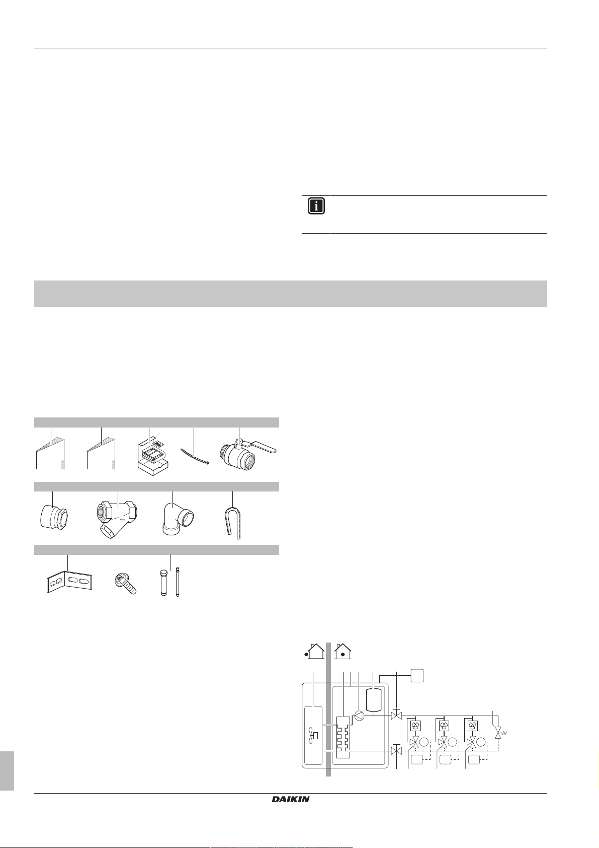
2 About the box
8×
a d ec
1×
b
1× 1×
f g
h
2×
1× 1×1×/2×
i
2×
j k
3×2×
l
2×
RC
RT1M1RT2M2RT3
M3
FC1 FC2 FC3
a c e f
f g g g
h
db
▪ General safety precautions:
▪ Safety instructions that you must read before installing
▪ Format: Paper (in the box of the outdoor unit)
▪ Outdoor unit installation and operation manual:
▪ Installation and operation instructions
▪ Format: Paper (in the box of the outdoor unit)
▪ Indoor unit installation and operation manual:
▪ Installation and operation instructions
▪ Format: Paper (in the box of the indoor unit)
▪ Installer and user reference guide:
▪ Preparation of the installation, reference data,…
▪ Detailed step-by-step instructions and background information
for basic and advanced usage
▪ Format: Digital files on http://www.daikineurope.com/support-
and-manuals/product-information/
For the installer
2 About the box
Latest revisions of the supplied documentation may be available on
the regional Daikin website or via your dealer.
The original documentation is written in English. All other languages
are translations.
Technical engineering data
▪ A subset of the latest technical data is available on the regional
Daikin website (publicly accessible).
▪ The full set of latest technical data is available on the Daikin
extranet (authentication required).
For installation of the heat pump unit (location, piping, and wiring),
refer to the installation and operation manual of the RXYQ*.
INFORMATION
First read the indoor unit manual, and only then the
outdoor unit manual.
3 About the units and options
2.1 Indoor unit
2.1.1 To remove the accessories from the indoor unit
a General safety precautions
b Installation manual and operation manual (panel 3)
c Remote controller (panel 3)
d Tie wraps (panel 3)
e Shut-off valves (panel 3)
f Threaded connection (panel 3) (1× for SEHVX20+32BAW,
2× for SEHVX40+64BAW)
g Filter (panel 3)
h Elbow (panel 3)
i Black grommet (2×)
j L-shaped support (2×)
k M5 screws (3×)
l Accessory pipes (Ø12.7→Ø9.52 and Ø25.4→Ø28.6)
3.1 About the indoor unit
This installation manual concerns the inverter heat pump chilling unit
with separate hydro module. The unit is intended for indoor
installation and can be combined with VRV outdoor units
(SERHQ020+032BAW1) for air conditioning purposes, or it can be
used for supplying water for process cooling applications.
The units are available in 4 standard sizes with nominal capacities
ranging from 16.8 to 63 kW.
The unit is designed to work in heating mode at ambient
temperatures from –15°C to 35°C and in cooling mode at ambient
temperatures from –5°C to 43°C.
The main component is the water heat exchanger.
The indoor unit is connected to the outdoor unit by field refrigerant
piping and the compressor in the outdoor unit circulates refrigerant
into the heat exchangers.
▪ In cooling mode, the refrigerant transports the heat taken from the
water heat exchanger to the air heat exchanger where the heat is
released to the air.
▪ In heating mode, the refrigerant transports the heat taken from the
air heat exchanger to the water heat exchanger where the heat is
released to the water.
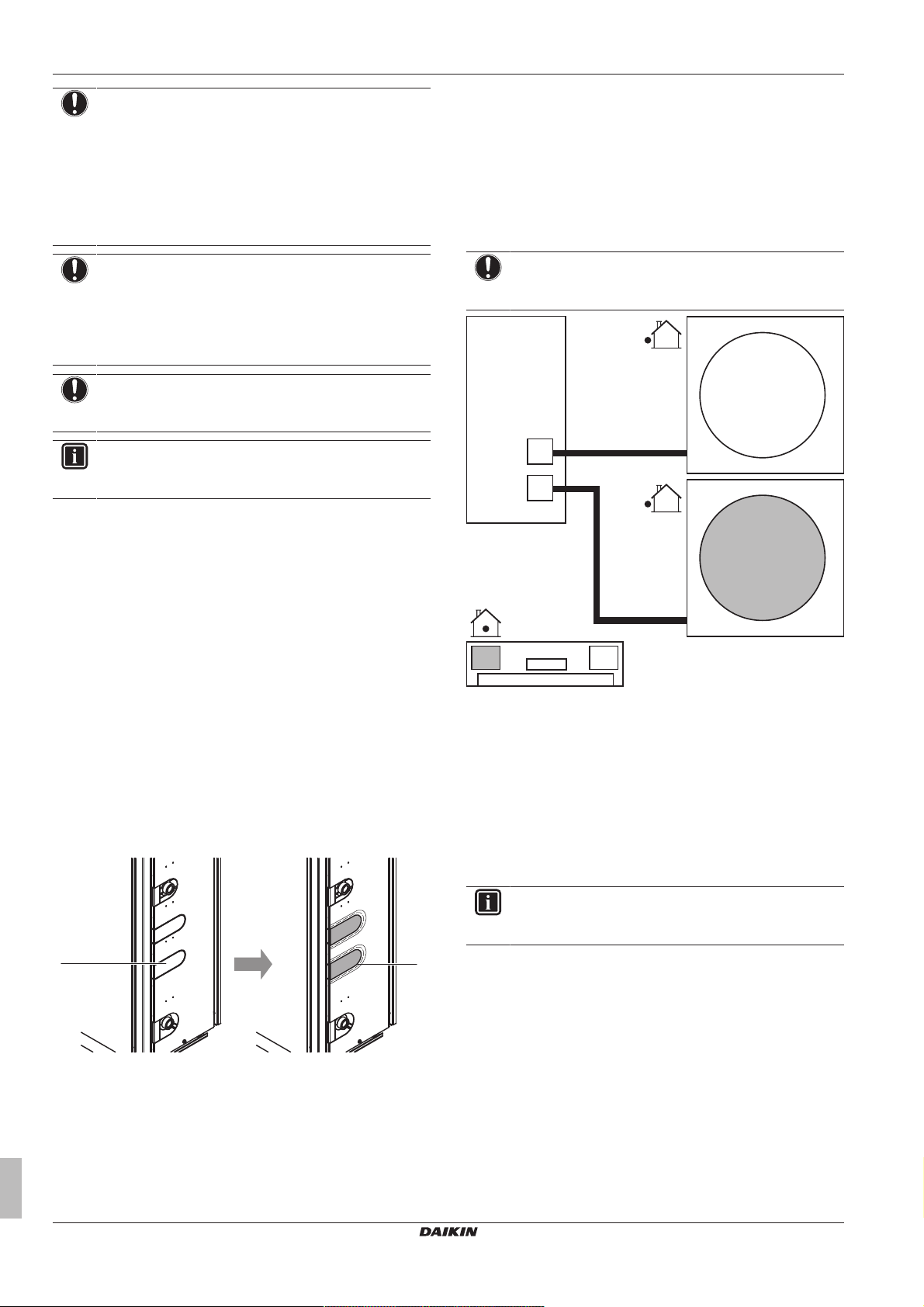
3.2 System layout
Installation and operation manual
4
SEHVX20~64BAW
Inverter heat pump chilling unit with separate hydro module
4P508019-1 – 2017.10
4 Preparation
a
b
a
c
d
b
a Outdoor unit
b Indoor unit
c Plate heat exchanger
d Pump
e Expansion vessel
f Shut-off valve
g Motorized valve
h Bypass valve
FC1…3 Fancoil unit (field supply)
RC Remote controller
RT1…3 Room thermostat
4 Preparation
4.1 Preparing the installation site
4.1.1 Installation site requirements of the indoor unit
Mind the spacing guidelines. See the "Technical data" chapter.
CAUTION
Appliance not accessible to the general public, install it in a
secured area, protected from easy access.
This unit, both indoor and outdoor, is suitable for
installation in a commercial and light industrial
environment.
▪ Non-brass metallic piping. When using non-brass metallic
piping, insulate the brass and non-brass properly so that they do
NOT make contact with each other. This to prevent galvanic
corrosion.
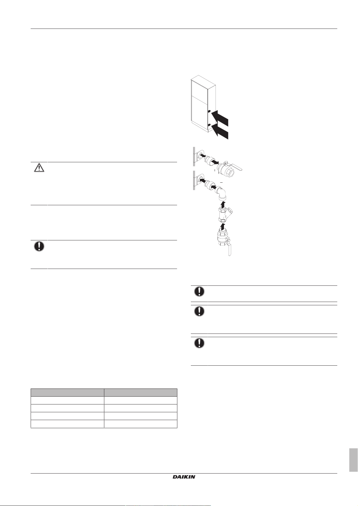
▪ Shut-off valves. Two shut-off valves are delivered with the unit.
Install them as shown in the following figure.
4.2 Preparing water piping
4.2.1 Water circuit requirements
NOTICE
In case of plastic pipes, make sure they are fully oxygen
diffusion tight according to DIN 4726. The diffusion of
oxygen into the piping can lead to excessive corrosion.
▪ Connecting piping – Legislation. Make all piping connections in
accordance with the applicable legislation and the instructions in
the "Installation" chapter, respecting the water inlet and outlet.
▪ Connecting piping – Force. Do NOT use excessive force when
connecting the piping. Deformation of the piping can cause
malfunctioning of the unit.
▪ Connecting piping – Tools. Only use appropriate tooling to
handle brass, which is a soft material. If NOT, pipes will get
damaged.
▪ Connecting piping – Air, moisture, dust. If air, moisture or dust
gets into the circuit, problems may occur. To prevent this:
▪ Only use clean pipes
▪ Hold the pipe end downwards when removing burrs.
▪ Cover the pipe end when inserting it through a wall, to prevent
dust and/or particles entering the pipe.
▪ Use a decent thread sealant to seal connections.
Capacity class Minimum required flow rate
20 23 l/min
32 36 l/min
40 46 l/min
64 72 l/min
▪ Field supply components – Water pressure and temperature.
Check that all components in the field piping can withstand the
water pressure and water temperature.
▪ Drainage – Low points. Provide drain taps at all low points of the
system in order to allow complete drainage of the water circuit.
a Adapter piece (on the inlet only in case of
SEHVX40+64BAW)
b Shut-off valve
c Bend
d Filter
NOTICE
Before mounting the bend, attach the filter to it.
NOTICE
If the bend is not used during installation, replace it with an
extension (5cm long for a 1¼" filter, and 6 cm long for a
2"filter) to ensure proper cleaning operation of the filter.
NOTICE
Be sure to install the filter properly. Failure to install or
incorrect installation will damage the plate heat exchanger
permanently.
▪ Drain taps. Drain taps must be provided at all low points of the
system to permit complete drainage of the circuit. A drain valve is
provided inside the unit.
▪ Air vents. Provide air vents at all high points of the system, which
must also be easily accessible for servicing. An automatic air
purge valve is provided inside the unit. Check that this air purge
valve is NOT tightened too much, so that automatic release of air
from the water circuit is possible. Refer to field setting [E‑04] in
"6.2.9Field settings on the remote controller"on page15.
SEHVX20~64BAW
Inverter heat pump chilling unit with separate hydro module
4P508019-1 – 2017.10
Installation and operation manual
5
4 Preparation
0.0
0.5
1.0
1.5
2.0
2.5
3.0
3.5
4.0
0 0.5 1 1.5 2 2.5 3 3.5 4 4.5 5 5.5 6 6.5 7 7.5 8 8.5
9
a
b
WARNING
▪ For correct operation of the system, a regulating valve
must be installed in the water system. The regulating
valve is to be used to regulate the water flow in the
system (field supply).
▪ Selecting a flow outside the curves can cause
malfunction or damage to the unit. Also refer to the
Technical specifications.
▪ The maximum water piping temperature is 50°C according to
safety device setting.
▪ Always use materials which are compatible with the water used in
the system and with the materials used in the unit. (The unit piping
fittings are made of brass, the plate heat exchangers are made of
stainless steel 316 plates brazed together with copper and the
optional pump housing is made of cast iron.)
▪ Select the piping diameter in relation to the required water flow
and available external static pressure (ESP) of the pump. See the
following table for the recommended water piping diameter.
Capacity class Water piping diameter
20+32 1-1/4"
40+64 2"
NOTICE
It is strongly recommended to install an additional filter on
the water circuit. Especially to remove metallic particles
from the field water piping, it is advised to use a magnetic
or cyclone filter which can remove small particles. Small
particles can damage the unit and will not be removed by
the standard filter of the unit.
▪ Water pressure. Take care that the components installed in the
field piping can withstand the water pressure (maximum 3 bar +
static pressure of the pump).
4.2.2 Formula to calculate the expansion vessel pre-pressure
The pre-pressure (Pg) of the vessel depends on the installation
height difference (H):
Pg=0.3+(H/10) (bar)
4.2.3 To check the water volume and expansion vessel pre-pressure
The unit has an expansion vessel of 12 litre with a default prepressure of 1bar.
See the installer and user reference guide for more information.
To make sure that the unit operates properly:
▪ You must check the minimum and maximum water volume.
▪ You might need to adjust the pre-pressure of the expansion
vessel.
Minimum water volume
Model Minimum total water volume (l)
20 76
32 110
40 152
64 220
INFORMATION
In critical processes, or in rooms with a high heat load,
extra water might be required.
Installation and operation manual
6
INFORMATION
The temperature step difference can be modified using
settings [A‑02] and [F‑00]. This has an impact on the
minimum water volume required when the unit operates in
cooling.
By default, the unit is set to have a water temperature
difference of 3.5 K which allows it to operate with the
minimum volume mentioned in the previous table.
However, if a smaller temperature differential is set, as in
the case of process cooling applications where
temperature fluctuations must be avoided, a larger
minimum water volume will be required.
To ensure proper operation of the unit when changing the
values of setting [F‑00] (for cooling mode), the minimum
water volume has to be corrected. If this volume exceeds
the range allowed in the unit, an additional expansion
vessel or a buffer tank must be installed in the field piping.
Example:
To illustrate the impact on the system when modifying the setting
[F‑00], we will consider a unit with a minimum allowable water
volume of 66 l. The unit is installed 5 m below the highest point in
the water circuit.
Assuming that the setting [F‑00] is changed from 5°C (default value)
to 0°C. From the below table we see that 5°C corresponds to a
temperature differential of 3.5K and 0°C to 1K, which is actually the
lowest value we can set.
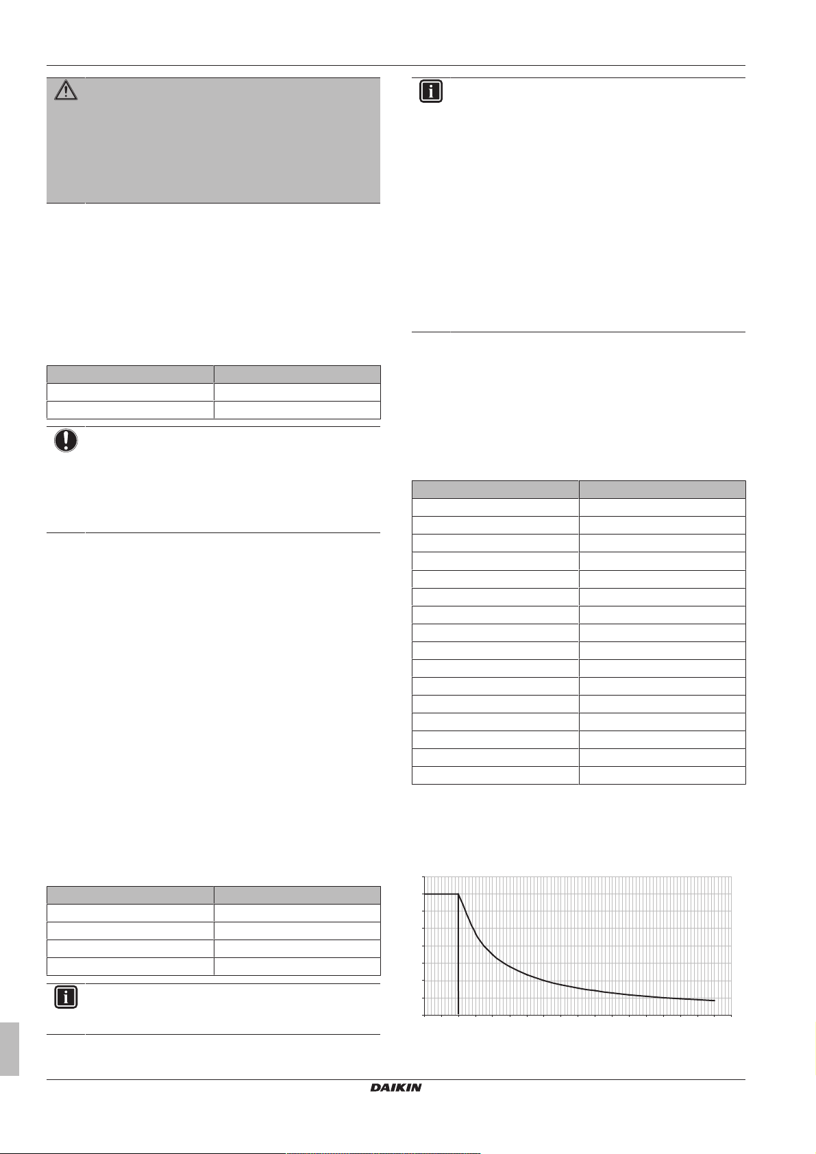
[F‑00] value (°C) Temperature differential (K)
0 1
1 1.5
2 2
3 2.5
4 3
5 3.5
6 4
7 4.5
8 5
9 5.5
10 6
11 6.5
12 7
13 7.5
14 8
15 8.5
The water volume correction factor according to the curve shown in
the below graph is 3.5; this means that the minimum volume will be
3.5 times larger.
Correction factor curve for minimum water volume
a Water volume correction factor
b Temperature differential (K)
SEHVX20~64BAW
Inverter heat pump chilling unit with separate hydro module
4P508019-1 – 2017.10
When multiplying 64 l by the correction factor, we get 224 l, which
0
0.5
1
1.5
2
2.5
3
0 50 100 150 200 250 300 350 400 450 500 550 600
A
B
33
b
a
a
G
L
G1
L2
G2
L1
1
2
will be the minimum water volume allowed in the installation if a
temperature differential of 1K is used.
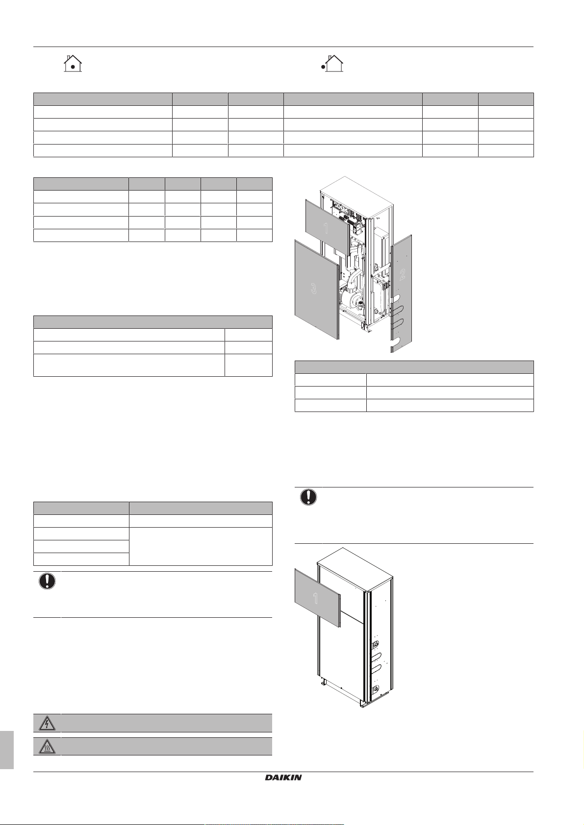
Now it is very important to check that for the height difference of the
system, the volume in the system is less than the maximum allowed
value at that pre-pressure (Pg). If we take a look at the curve, for
1bar of pre-pressure, the maximum volume allowed is 350l.
The total volume in the system will definitely be larger after adding
the internal volume of the unit. In this case, some pre-pressure can
be applied or an additional expansion vessel or buffer tank must be
installed in the field piping.
The default value of pre-pressure (Pg) is for a height difference of
7m.
If the height difference of the system is lower than 7 m AND the
volume in the system is less than the maximum allowed value at that
pre-pressure (Pg) (see graph), then NO pre-pressure (Pg)
adjustment is required.
Maximum water volume
Use the following graph to determine the maximum water volume for
the calculated pre-pressure.
a Pre-pressure (bar)
b Maximum water volume (l)
A System
B Default
If the total water volume in the entire circuit exceeds the maximum
allowed water volume (see graph), an additional expansion vessel
must be installed in the field piping.
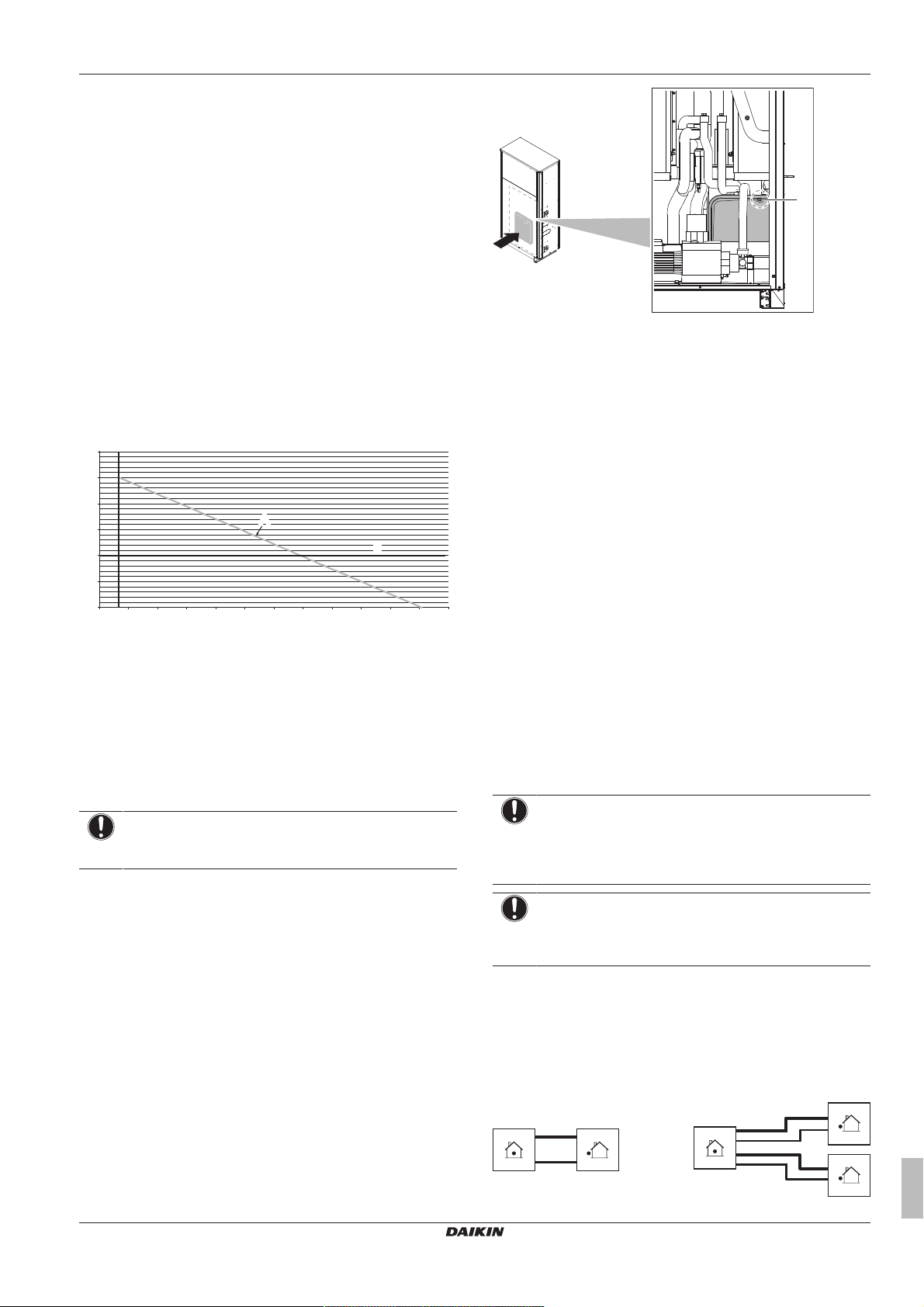
4 Preparation
a Schrader valve
4.2.5 To check the water volume: Examples
Example 1
The unit is installed 5m below the highest point in the water circuit.
The total water volume in the water circuit is 250l.
No actions or adjustments are required.
Example 2
The unit is installed at the highest point in the water circuit. The total
water volume in the water circuit is 420l.
Actions:
▪ Because the total water volume (420 l) is more than the default
water volume (340l), the pre-pressure must be decreased.
▪ The required pre-pressure is:
Pg=(0.3+(H/10))bar=(0.3+(0/10))bar=0.3bar
▪ The corresponding maximum water volume is approximately 490l
(see graph).
▪ Because 420 l is lower than 490 l, the expansion vessel is
appropriate for the installation.
4.3 Preparing refrigerant piping
4.2.4 Changing the pre-pressure of the expansion vessel
NOTICE
Only a licensed installer may adjust the pre-pressure of the
expansion vessel.
When changing the default pre-pressure of the expansion vessel
(1bar) is required, take following guidelines into account:
▪ Only use dry nitrogen to set the expansion vessel pre-pressure.
▪ Inappropriate setting of the expansion vessel pre-pressure will
lead to malfunction of the system.
Changing the pre-pressure of the expansion vessel should be done
by releasing or increasing nitrogen pressure through the Schrader
valve of the expansion vessel.
SEHVX20~64BAW
Inverter heat pump chilling unit with separate hydro module
4P508019-1 – 2017.10
4.3.1 Refrigerant piping requirements
NOTICE
Refrigerant R410A requires strict cautions for keeping the
system clean and dry. Foreign materials (including mineral
oils or moisture) should be prevented from getting mixed
into the system.
NOTICE
The piping and other pressure-containing parts shall be
suitable for refrigerant. Use phosphoric acid deoxidised
seamless copper for refrigerant.
▪ All piping lengths and distances have been taken into
consideration (see About the piping length in the installer
reference guide).
4.3.2 To select the piping size
Determine the proper size using the following tables and reference
figure (only for indication).
Installation and operation manual
7
5 Installation
1
3
2
1
Indoor unit (hydro module) Outdoor unit (heat pump unit)
▪ Piping connection sizes
Hydro module Gas Liquid Heat pump unit Gas Liquid
SEHVX20BAW 25.4 12.7 1× SERHQ020BAW1 22.2 9.52
SEHVX32BAW 25.4 12.7 1× SERHQ032BAW1 28.6 12.7
SEHVX40BAW 25.4 12.7 2× SERHQ020BAW1 22.2 9.52
SEHVX64BAW 25.4 12.7 2× SERHQ032BAW1 28.6 12.7
▪ Field piping sizes
Model G/G1 L/L1 G2 L2
SEHVX20BAW 28.6 9.52 — —
SEHVX32BAW 28.6 12.7 — —
SEHVX40BAW 28.6 9.52 28.6 9.52
SEHVX64BAW 28.6 12.7 28.6 12.7
If the hydro module connections do not match the diameter of the
specified piping requirements, the piping diameter requirements
must be met using reducers/expanders (field supply) on the hydro
module connections.
4.3.3 About the piping length
Maximum piping length and height difference
Maximum allowable piping length 30m
Height difference between indoor and outdoor unit <10m
Height difference between outdoor unit 1 and outdoor
unit 2 (if applicable)
0m
4.4 Preparing electrical wiring
4.4.1 Safety device requirements
The power supply must be protected with the required safety
devices, i.e. a main switch, a slow blow fuse on each phase and an
earth leakage protector in accordance with the applicable legislation.
Selection and sizing of the wiring should be done in accordance with
the applicable legislation based on the information mentioned in the
table below.
Model Recommended fuses
SEHVX20BAW 6A
SEHVX32BAW 10A
SEHVX40BAW
SEHVX64BAW
To gain access to the unit, front plates need to be opened as follows:
Panel
1 Electrical parts of the hydro module
2 Hydro module (side panel)
3 Hydro module (front panel)
Once the front plates open, the electrical component box can be
accessed. See "5.1.2To open the electrical component box of the
indoor unit"on page8.
5.1.2 To open the electrical component box of the indoor unit
NOTICE
Do NOT apply excessive force when opening the
electronic component box cover. Excessive force can
deform the cover, resulting in entering of water to cause
equipment failure.
NOTICE
When using residual current operated circuit breakers, be
sure to use a high-speed type 300 mA rated residual
operating current.
5 Installation
5.1 Opening the units
5.1.1 To open the indoor unit
DANGER: RISK OF ELECTROCUTION
DANGER: RISK OF BURNING
Installation and operation manual
8
Inverter heat pump chilling unit with separate hydro module
SEHVX20~64BAW
4P508019-1 – 2017.10
5 Installation
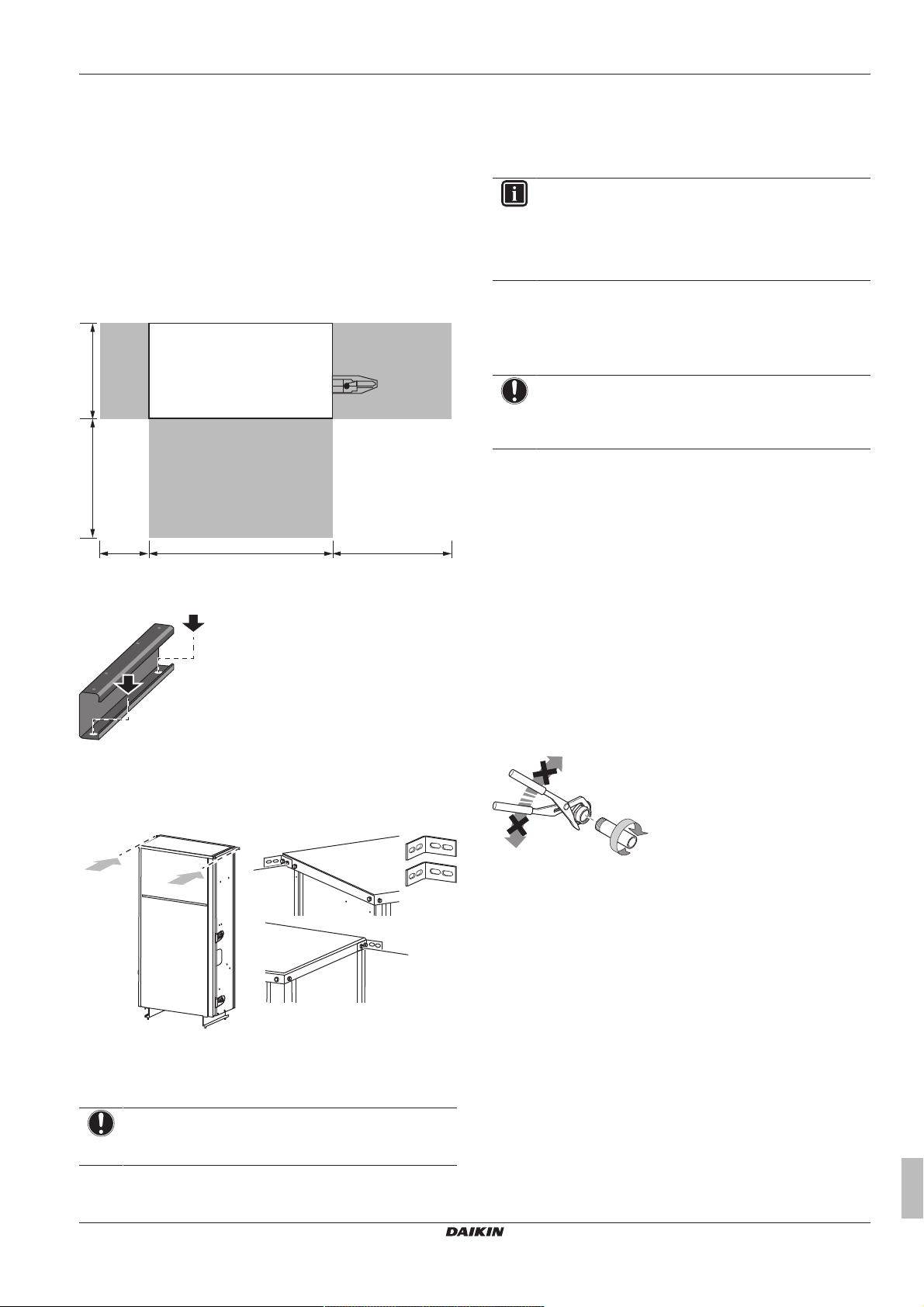
766.5 500200
396500
(mm)
a
b
5.2 Mounting the indoor unit
5.2.1 To provide the installation structure
Make sure the unit is installed level on a sufficiently strong base to
prevent vibration and noise.
▪ The unit must be mounted against the wall.
▪ The unit must be fixed to prevent it from tilting.
▪ The preferred installation is on a solid longitudinal foundation
(steel beam frame or concrete).
▪ Observe the minimum installation space requirements.
▪ Fasten the unit to the floor using the holes in the bottom beams.
▪ Fasten the unit to the wall using the 2 accessory L-shaped
supports to prevent it from falling over. The supports can be fixed
to the top panel of the hydro module (2× M5 screws on either side,
but one screw is already mounted on the right side of the top
plate).
5.3 Connecting the water piping
5.3.1 Precautions when connecting the water piping
INFORMATION
Also read the precautions and requirements in the
following chapters:
▪ General safety precautions
▪ Preparation
To connect the water piping
Water connections must be made in accordance with all applicable
legislations and the outlook drawing delivered with the unit,
respecting the water inlet and outlet.
NOTICE
Do NOT use excessive force when connecting the piping.
Deformation of the piping can cause malfunctioning of the
unit.
If dirt gets in the water circuit, problems may occur. Therefore,
always take into account the following when connecting the water
circuit:
▪ Use clean pipes only.
▪ Hold the pipe end downwards when removing burrs.
▪ Cover the pipe end when inserting it through a wall so that no dust
and dirt enter.
▪ Use a good thread sealant for the sealing of the connections. The
sealing must be able to withstand the pressures and temperatures
of the system.
▪ When using non-brass metallic piping, make sure to insulate both
materials from each other to prevent galvanic corrosion.
▪ Make sure to provide a proper drain for the pressure relief valve.
▪ Because brass is a soft material, use appropriate tooling for
connecting the water circuit. Inappropriate tooling will cause
damage to the pipes.
a Attach one L-shaped support to the left side of the top plate
using 2screws from the accessory bag
b Attach the other L-shaped support to the right side of the
top plate using 1screw from the accessory bag and
1screw that is already attached to the unit
NOTICE
Use the proper kind of screw for the type of wall or
foundation material where the unit will be fixed to.
SEHVX20~64BAW
Inverter heat pump chilling unit with separate hydro module
4P508019-1 – 2017.10
▪ For correct operation of the system, a regulating valve must be
installed in the water system. The regulating valve is to be used to
regulate the water flow in the system (field supply).
5.3.2 To fill the water circuit
1 Connect the water supply to the drain and fill valve.
2 Make sure the automatic air purge valve is open (at least 2
turns).
3 Fill with water until the pressure gauge indicates a pressure of
approximately 2.0 bar. Remove air in the circuit as much as
possible using the air purge valves (refer to field setting [E‑04]
in "6.2.9Field settings on the remote controller"on page15).
Installation and operation manual
9
5 Installation
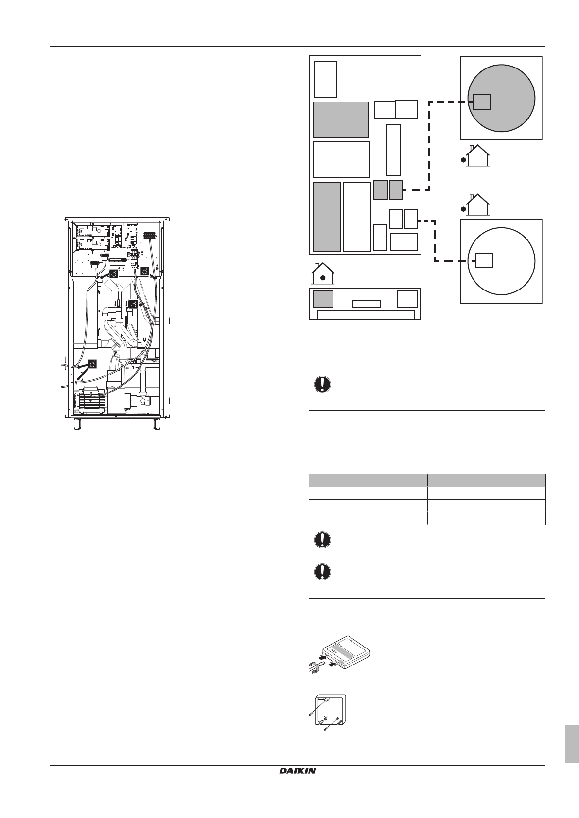
a
b
VRV
C1
VRV
C2
f
e
g
C2
g
C1
C1
C2
d
d
a
b
c
NOTICE
▪ Air in the water circuit can cause malfunctioning. During
filling, it may not be possible to remove all the air from
the circuit. Remaining air will be removed through the
automatic air purge valves during the initial operating
hours of the system. Additional filling with water
afterwards may be required.
▪ To purge the system, use the special function as
described in "7Commissioning"on page20.
NOTICE
The water pressure indicated on the manometer will vary
depending on the water temperature (higher pressure at
higher water temperature).
However, at all times water pressure shall remain above
1bar to avoid air entering the circuit.
NOTICE
Make sure water quality complies with EU directive
98/83EC.
INFORMATION
The unit may dispose of some excessive water through the
pressure relief valve.
5.3.3 To insulate the water piping
The complete water circuit, inclusive all piping, must be insulated to
prevent condensation during cooling operation and reduction of the
heating and cooling capacity as well as prevention of freezing of the
outside water piping during winter time. The thickness of the
insulation materials must be at least 13mm with λ=0.039W/mK in
order to prevent freezing of the outside water piping at ambient
temperature of –15°C.
If the temperature is higher than 30°C and the humidity is higher
than RH 80%, the thickness of the insulation materials should be at
least 20 mm to prevent condensation on the surface of the
insulation.
5.4 Connecting the refrigerant piping
▪ For the SEHVX20+32BAW, remove the top knockout hole in the
side service plate and add the grommet (accessory) to cover any
burrs. For the SEHVX40+64BAW, remove both top and bottom
knockout holes in the side service plate and add the grommets
(accessory) to cover any burrs.
▪ Use accessory pipes to connect field refrigerant piping to the
piping connections on the hydro module. For SEHVX20BAW, after
cutting off the end of both the liquid and gas refrigerant piping,
braze accessory pipe 1 to the liquid connection and accessory
pipe 2 to the gas connection. For SEHVX32BAW, after cutting off
the end of both the liquid and gas refrigerant piping, braze the field
piping directly to the liquid connection and accessory pipe 2 to the
gas connection. For SEHVX40BAW, perform the procedure for
SEHVX20BAW twice. For SEHVX64BAW, perform the procedure
for SEHVX32BAW twice.
NOTICE
After brazing, fix the pipes to the unit using the clamps in
the pipe supports.
a Indoor unit
b Outdoor unit 1
c Outdoor unit 2 (only in case of SEHVX40+64BAW)
d Refrigerant piping
e Pump
f Switchbox
g Evaporator
5.5 Charging refrigerant
5.5.1 To determine the additional refrigerant amount
INFORMATION
For final charge adjustment in a test laboratory, contact
your dealer.
Refrigerant type: R410A
Global warming potential (GWP) value: 2087.5
The additional refrigerant charge calculation is based on the liquid
piping size.
Formula:
R=(X
×0.059)+(X
Ø9.52
R Additional refrigerant to be charged [in kg and rounded off
X
1, 2
×0.12)
Ø12.7
to 1 decimal place]
Total length [m] of liquid piping size at Øa
Example
SEHVX64BAW + 2× SERHQ032BAW1
R=(L1+L2)
×0.12
Ø12.7
Inverter heat pump chilling unit with separate hydro module
SEHVX20~64BAW
4P508019-1 – 2017.10
▪ First cut off the refrigerant liquid piping inside the unit
approximately 7 cm before the clamp and the refrigerant gas
a Knockout hole
b Grommet
piping 4 cm before the clamp. This is necessary in order to avoid
the piping cutter tool from interfering with the piping. Remove any
burrs from the piping.
Installation and operation manual
10
5.6 Connecting the electrical wiring
LVLV PSPS
LV
PS
HV
VRV
C2
VRV
C1
e
d
f
C2
f
C1
c
b
A5PC2A1P
C1
A3P
C1
X1M
K1P
K1S
A8P
C2
X2M
X4M
F1F2
F1F2
X3M
A6P
A4P
F1F2
F1F2
a
5.6.1 Field wiring: Overview
▪ Most field wiring on the unit is to be made on the terminal blocks
inside the electrical component boxes. To gain access to the
terminal blocks, remove the electrical component box service
panel. See "5.1Opening the units"on page8.
▪ Cable tie mountings are provided at the wiring entries of the
electrical component box.
The wiring diagram is delivered with the unit, located at the inside of
the switch box cover.
5.6.2 To route and fix the power supply
5 Installation
PS Power supply
HV High voltage
LV Low voltage
Guide the cables as much as possible through the provided cable
entry glands.
5.6.3 To connect the power supply and transmission cables
1 Open the electrical component box cover.
2 Using the appropriate cable, connect the power supply and
communication cable(s) to the appropriate terminals as shown
on the wiring diagram.
3 Fix the cables with cable ties to the cable tie mountings to
ensure strain relief and to make sure that they do not come in
contact with the piping and sharp edges. Never squeeze
bundled cables.
4 Close the electrical component box cover.
a Switchbox
b Outdoor unit 1
c Outdoor unit 2 (only in case of SEHVX40+64BAW)
d Pump
e Switchbox
f Evaporator
NOTICE
The power supply cable and the communication cable are
not included.
5.6.4 To install the remote controller
The unit comes with a remote controller offering a user-friendly way
to set up, use and maintain the unit. Before operating the remote
controller, follow this installation procedure.
Wire specification Value
Type 2 wire
Section 0.75~1.25 mm
Maximum length 500 m
NOTICE
The wiring for connection is NOT included.
NOTICE
The accessory remote controller MUST be mounted
indoors.
1 Insert a slotted screwdriver into the slots in the rear part of the
remote controller, and remove the front part of the remote
controller.
2
SEHVX20~64BAW
Inverter heat pump chilling unit with separate hydro module
4P508019-1 – 2017.10
2 Fasten the remote controller on a flat surface.
Installation and operation manual
11
 Loading...