

Daikin SERHQ020BAW1, SERHQ032BAW1, SEHVX20BAW, SEHVX32BAW, SEHVX40BAW Installer reference guide
...
Installer and user
reference guide
Split packaged air-cooled water chiller
SERHQ020BAW1
SERHQ032BAW1
SEHVX20BAW
SEHVX32BAW
SEHVX40BAW
SEHVX64BAW
Installer and user reference guide
Split packaged air-cooled water chiller
English

Table of contents
Table of contents
1 General safety precautions 3
1.1 About the documentation .......................................................... 3
1.1.1 Meaning of warnings and symbols.............................. 3
1.2 For the user ............................................................................... 4
1.3 For the installer.......................................................................... 4
1.3.1 General ....................................................................... 4
1.3.2 Installation site ............................................................ 4
1.3.3 Refrigerant .................................................................. 5
1.3.4 Brine............................................................................ 5
1.3.5 Water .......................................................................... 6
1.3.6 Electrical ..................................................................... 6
2 About the documentation 6
2.1 About this document.................................................................. 6
2.2 Installer and user reference guide at a glance .......................... 7
For the installer 7
3 About the box 7
3.1 Overview: About the box ........................................................... 7
3.2 Outdoor unit............................................................................... 8
3.2.1 To unpack the outdoor unit ......................................... 8
3.2.2 To handle the outdoor unit.......................................... 8
3.2.3 To remove the accessories from the outdoor unit....... 8
3.3 Indoor unit ................................................................................. 8
3.3.1 To unpack the indoor unit ........................................... 8
3.3.2 To handle the indoor unit ............................................ 9
3.3.3 To remove the accessories from the indoor unit......... 9
4 About the units and options 9
4.1 Overview: About the units and options...................................... 9
4.2 Identification .............................................................................. 9
4.2.1 Identification label: Outdoor unit ................................. 10
4.2.2 Identification label: Indoor unit .................................... 10
4.2.3 About the outdoor unit................................................. 10
4.2.4 About the indoor unit................................................... 10
4.2.5 About combining units and options............................. 10
4.2.6 Operation range .......................................................... 10
4.3 Combining units and options ..................................................... 11
4.3.1 Possible options for the split system........................... 11
4.4 System layout............................................................................ 11
5 Preparation 11
5.1 Overview: Preparation............................................................... 11
5.2 Preparing the installation site .................................................... 11
5.2.1 Installation site requirements of the outdoor unit ........ 11
5.2.2 Installation site requirements of the indoor unit .......... 12
5.3 Preparing refrigerant piping....................................................... 13
5.3.1 Refrigerant piping requirements.................................. 13
5.3.2 To select the piping size ............................................. 13
5.3.3 About the piping length ............................................... 13
5.4 Preparing water piping .............................................................. 13
5.4.1 Water circuit requirements .......................................... 13
5.4.2 Formula to calculate the expansion vessel pre-
pressure ...................................................................... 15
5.4.3 To check the water volume and expansion vessel
pre-pressure................................................................ 15
5.4.4 Changing the pre-pressure of the expansion vessel... 16
5.4.5 To check the water volume: Examples ....................... 16
5.5 Preparing electrical wiring ......................................................... 16
5.5.1 About preparing electrical wiring................................. 16
5.5.2 About electrical compliance ........................................ 16
5.5.3 Cable requirements..................................................... 17
5.5.4 Safety device requirements ........................................ 17
6 Installation 17
6.1 Overview: Installation ................................................................. 17
6.2 Opening the units ....................................................................... 17
6.2.1 About opening the units ............................................... 17
6.2.2 To open the outdoor unit.............................................. 17
6.2.3 To open the indoor unit ................................................ 18
6.2.4 To open the electrical component box of the outdoor
unit ............................................................................... 18
6.2.5 To open the electrical component box of the indoor
unit ............................................................................... 18
6.3 Mounting the outdoor unit........................................................... 18
6.3.1 About mounting the outdoor unit.................................. 18
6.3.2 Precautions when mounting the outdoor unit............... 19
6.3.3 To provide the installation structure ............................. 19
6.3.4 To provide drainage ..................................................... 19
6.4 Mounting the indoor unit............................................................. 19
6.4.1 About mounting the indoor unit .................................... 19
6.4.2 Precautions when mounting the indoor unit................. 19
6.4.3 To provide the installation structure ............................. 19
6.5 Connecting the refrigerant piping ............................................... 20
6.5.1 Precautions when connecting the refrigerant piping .... 20
6.5.2 To braze the pipe end .................................................. 20
6.5.3 Using the stop valve and service port .......................... 21
6.5.4 To connect the refrigerant piping to the outdoor unit ... 21
6.5.5 To connect the refrigerant piping to the indoor unit ..... 23
6.6 Checking the refrigerant piping .................................................. 23
6.6.1 About checking the refrigerant piping .......................... 23
6.6.2 Precautions when checking the refrigerant piping ....... 24
6.6.3 Checking refrigerant piping: Setup............................... 24
6.6.4 To check for leaks: Pressure leak test ......................... 24
6.6.5 To perform vacuum drying ........................................... 24
6.6.6 To insulate the refrigerant piping ................................. 24
6.7 Charging refrigerant ................................................................... 25
6.7.1 About charging refrigerant ........................................... 25
6.7.2 Precautions when charging refrigerant ........................ 25
6.7.3 To determine the additional refrigerant amount ........... 25
6.7.4 To charge refrigerant ................................................... 25
6.7.5 Checks after charging refrigerant................................. 25
6.7.6 To fix the fluorinated greenhouse gases label ............. 26
6.8 Connecting water piping............................................................. 26
6.8.1 About connecting the water piping............................... 26
6.8.2 Precautions when connecting the water piping............ 26
6.8.3 To connect the water piping......................................... 26
6.8.4 To fill the water circuit .................................................. 26
6.8.5 To insulate the water piping ......................................... 27
6.9 Connecting the electrical wiring.................................................. 27
6.9.1 About connecting the electrical wiring.......................... 27
6.9.2 Precautions when connecting the electrical wiring ...... 27
6.9.3 Field wiring: Overview.................................................. 28
6.9.4 About the electrical wiring ............................................ 28
6.9.5 To route and fix the power supply................................ 29
6.9.6 To connect the power supply of the outdoor unit ......... 29
6.9.7 To connect the power supply and transmission
cables........................................................................... 31
6.9.8 Guidelines when knocking out knockout holes ............ 31
6.9.9 To install the user interface.......................................... 31
6.9.10 To install optional equipment ....................................... 32
7 Configuration 32
7.1 Overview: Configuration ............................................................. 32
7.2 Making field settings................................................................... 32
7.2.1 About making field settings
7.2.2 Field setting components ............................................. 33
7.2.3 To access the field setting components....................... 33
7.2.4 To access mode 1 or 2 ................................................ 33
7.2.5 To use mode 1 ............................................................. 34
7.2.6 To use mode 2 ............................................................. 34
7.2.7 Mode 1: Monitoring settings......................................... 34
7.2.8 Mode 2: Field settings.................................................. 34
7.2.9 Field settings on the user interface .............................. 35
.......................................... 32
Installer and user reference guide
2
SERHQ020~032BAW1 + SEHVX20~64BAW
Split packaged air-cooled water chiller
4P508020-1C – 2019.11
1 General safety precautions
7.3 Switching between cooling and heating .................................... 40
8 Commissioning 40
8.1 Overview: Commissioning......................................................... 40
8.2 Precautions when commissioning ............................................. 41
8.3 Checklist before commissioning the outdoor unit...................... 41
8.4 Checklist before commissioning the indoor unit ........................ 41
8.5 Final check ................................................................................ 42
8.6 About the test run ...................................................................... 42
8.6.1 To display the temperature on the remote controller .. 43
8.6.2 To test space heating/cooling ..................................... 43
8.7 Correcting after abnormal completion of the test run ................ 43
8.8 Checklist handover to the user.................................................. 43
8.9 To complete the model fill-in ..................................................... 43
9 Maintenance and service 44
9.1 Overview: Maintenance and service ......................................... 44
9.2 Maintenance safety precautions................................................ 44
9.2.1 To prevent electrical hazards...................................... 44
9.3 About service mode operation................................................... 44
9.3.1 To use vacuum mode ................................................. 44
9.3.2 To recover refrigerant ................................................. 44
9.4 Checklist for yearly maintenance of the indoor unit................... 45
10 Troubleshooting 45
10.1 Overview: Troubleshooting........................................................ 45
10.2 Error codes: Overview ............................................................... 45
11 Disposal 46
12 Technical data 46
12.1 Overview: Technical data .......................................................... 46
12.2 Service space: Outdoor unit ...................................................... 46
12.3 Service space: Indoor unit ......................................................... 47
12.4 Piping diagram: Outdoor unit..................................................... 48
12.5 Piping diagram: Indoor unit ....................................................... 49
12.6 Wiring diagram: Outdoor unit .................................................... 50
12.7 Wiring diagram: Indoor unit ....................................................... 50
12.8 Technical specifications: Outdoor unit....................................... 51
12.9 Field settings on the user interface – overview ......................... 52
12.10 Field settings on the outdoor unit .............................................. 54
12.11 ESP curve: Indoor unit .............................................................. 55
For the user 55
13 About the system 55
13.1 System layout ............................................................................ 55
14 User interface 56
15 Before operation 56
17.2.3 Recommended maintenance and inspection cycles .... 65
18 Troubleshooting 65
18.1 Error codes: Overview ................................................................ 66
19 Relocation 66
20 Disposal 66
21 Glossary 67
1 General safety precautions
1.1 About the documentation
▪ The original documentation is written in English. All other
languages are translations.
▪ The precautions described in this document cover very important
topics, follow them carefully.
▪ The installation of the system, and all activities described in the
installation manual and in the installer reference guide MUST be
performed by an authorised installer.
1.1.1 Meaning of warnings and symbols
DANGER
Indicates a situation that results in death or serious injury.
DANGER: RISK OF ELECTROCUTION
Indicates a situation that could result in electrocution.
DANGER: RISK OF BURNING
Indicates a situation that could result in burning because of
extreme hot or cold temperatures.
DANGER: RISK OF EXPLOSION
Indicates a situation that could result in explosion.
WARNING
Indicates a situation that could result in death or serious
injury.
WARNING: FLAMMABLE MATERIAL
CAUTION
Indicates a situation that could result in minor or moderate
injury.
16 Operation 57
16.1 Operation range ........................................................................ 57
16.2 Quick start-up ............................................................................ 57
16.3 Operating the system ................................................................ 58
16.3.1 About the clock ........................................................... 58
16.3.2 About operating the system ........................................ 59
16.3.3 Space cooling operation ............................................. 59
16.3.4 Space heating operation ............................................. 59
16.3.5 Other operation modes ............................................... 60
16.3.6 Schedule timer ............................................................ 60
16.3.7 Operating the optional demand PCB .......................... 64
16.3.8 Operating the optional external control adapter .......... 64
16.3.9 Operating the optional remote controller..................... 64
17 Maintenance and service 64
17.1 About the refrigerant.................................................................. 65
17.2 After-sales service and warranty ............................................... 65
17.2.1 Warranty period .......................................................... 65
17.2.2 Recommended maintenance and inspection .............. 65
SERHQ020~032BAW1 + SEHVX20~64BAW
Split packaged air-cooled water chiller
4P508020-1C – 2019.11
NOTICE
Indicates a situation that could result in equipment or
property damage.
INFORMATION
Indicates useful tips or additional information.
Symbol Explanation
Before installation, read the installation and
operation manual, and the wiring instruction sheet.
Before performing maintenance and service tasks,
read the service manual.
For more information, see the installer and user
reference guide.
Installer and user reference guide
3
1 General safety precautions
1.2 For the user
▪ If you are NOT sure how to operate the unit, contact your installer.
▪ This appliance can be used by children aged from 8 years and
above and persons with reduced physical, sensory or mental
capabilities or lack of experience and knowledge if they have been
given supervision or instruction concerning use of the appliance in
a safe way and understand the hazards involved. Children shall
NOT play with the appliance. Cleaning and user maintenance
shall NOT be made by children without supervision.
WARNING
To prevent electric shocks or fire:
▪ Do NOT rinse the unit.
▪ Do NOT operate the unit with wet hands.
▪ Do NOT place any objects containing water on the unit.
NOTICE
▪ Do NOT place any objects or equipment on top of the
unit.
▪ Do NOT sit, climb or stand on the unit.
▪ Units are marked with the following symbol:
This means that electrical and electronic products may NOT be
mixed with unsorted household waste. Do NOT try to dismantle
the system yourself: the dismantling of the system, treatment of
the refrigerant, of oil and of other parts must be done by an
authorized installer and must comply with applicable legislation.
Units must be treated at a specialized treatment facility for reuse,
recycling and recovery. By ensuring this product is disposed of
correctly, you will help to prevent potential negative consequences
for the environment and human health. For more information,
contact your installer or local authority.
▪ Batteries are marked with the following symbol:
This means that the batteries may NOT be mixed with unsorted
household waste. If a chemical symbol is printed beneath the
symbol, this chemical symbol means that the battery contains a
heavy metal above a certain concentration.
Possible chemical symbols are: Pb: lead (>0.004%).
Waste batteries must be treated at a specialized treatment facility
for reuse. By ensuring waste batteries are disposed of correctly,
you will help to prevent potential negative consequences for the
environment and human health.
1.3 For the installer
WARNING
Make sure installation, testing and applied materials
comply with applicable legislation (on top of the
instructions described in the Daikin documentation).
CAUTION
Wear adequate personal protective equipment (protective
gloves, safety glasses,…) when installing, maintaining or
servicing the system.
WARNING
Tear apart and throw away plastic packaging bags so that
nobody, especially children, can play with them. Possible
risk: suffocation.
DANGER: RISK OF BURNING
▪ Do NOT touch the refrigerant piping, water piping or
internal parts during and immediately after operation. It
could be too hot or too cold. Give it time to return to
normal temperature. If you must touch it, wear
protective gloves.
▪ Do NOT touch any accidental leaking refrigerant.
WARNING
Provide adequate measures to prevent that the unit can be
used as a shelter by small animals. Small animals that
make contact with electrical parts can cause malfunctions,
smoke or fire.
CAUTION
Do NOT touch the air inlet or aluminium fins of the unit.
NOTICE
▪ Do NOT place any objects or equipment on top of the
unit.
▪ Do NOT sit, climb or stand on the unit.
NOTICE
Works executed on the outdoor unit are best done under
dry weather conditions to avoid water ingress.
In accordance with the applicable legislation, it might be necessary
to provide a logbook with the product containing at least: information
on maintenance, repair work, results of tests, stand-by periods,…
Also, at least, following information MUST be provided at an
accessible place at the product:
▪ Instructions for shutting down the system in case of an emergency
▪ Name and address of fire department, police and hospital
▪ Name, address and day and night telephone numbers for
obtaining service
In Europe, EN378 provides the necessary guidance for this logbook.
1.3.1 General
If you are NOT sure how to install or operate the unit, contact your
dealer.
NOTICE
Improper installation or attachment of equipment or
accessories could result in electric shock, short-circuit,
leaks, fire or other damage to the equipment. Only use
accessories, optional equipment and spare parts made or
approved by Daikin.
Installer and user reference guide
4
1.3.2 Installation site
▪ Provide sufficient space around the unit for servicing and air
circulation.
▪ Make sure the installation site withstands the weight and vibration
of the unit.
▪ Make sure the area is well ventilated. Do NOT block any
ventilation openings.
▪ Make sure the unit is level.
Do NOT install the unit in the following places:
▪ In potentially explosive atmospheres.
SERHQ020~032BAW1 + SEHVX20~64BAW
Split packaged air-cooled water chiller
4P508020-1C – 2019.11
1 General safety precautions
▪ In places where there is machinery that emits electromagnetic
waves. Electromagnetic waves may disturb the control system,
and cause malfunction of the equipment.
▪ In places where there is a risk of fire due to the leakage of
flammable gases (example: thinner or gasoline), carbon fibre,
ignitable dust.
▪ In places where corrosive gas (example: sulphurous acid gas) is
produced. Corrosion of copper pipes or soldered parts may cause
the refrigerant to leak.
1.3.3 Refrigerant
If applicable. See the installation manual or installer reference guide
of your application for more information.
NOTICE
Make sure refrigerant piping installation complies with
applicable legislation. In Europe, EN378 is the applicable
standard.
NOTICE
Make sure the field piping and connections are NOT
subjected to stress.
WARNING
During tests, NEVER pressurize the product with a
pressure higher than the maximum allowable pressure (as
indicated on the nameplate of the unit).
WARNING
Make sure there is no oxygen in the system. Refrigerant
may only be charged after performing the leak test and the
vacuum drying.
▪ In case recharge is required, see the nameplate of the unit. It
states the type of refrigerant and necessary amount.
▪ The unit is factory charged with refrigerant and depending on pipe
sizes and pipe lengths some systems require additional charging
of refrigerant.
▪ Only use tools exclusively for the refrigerant type used in the
system, this to ensure pressure resistance and prevent foreign
materials from entering into the system.
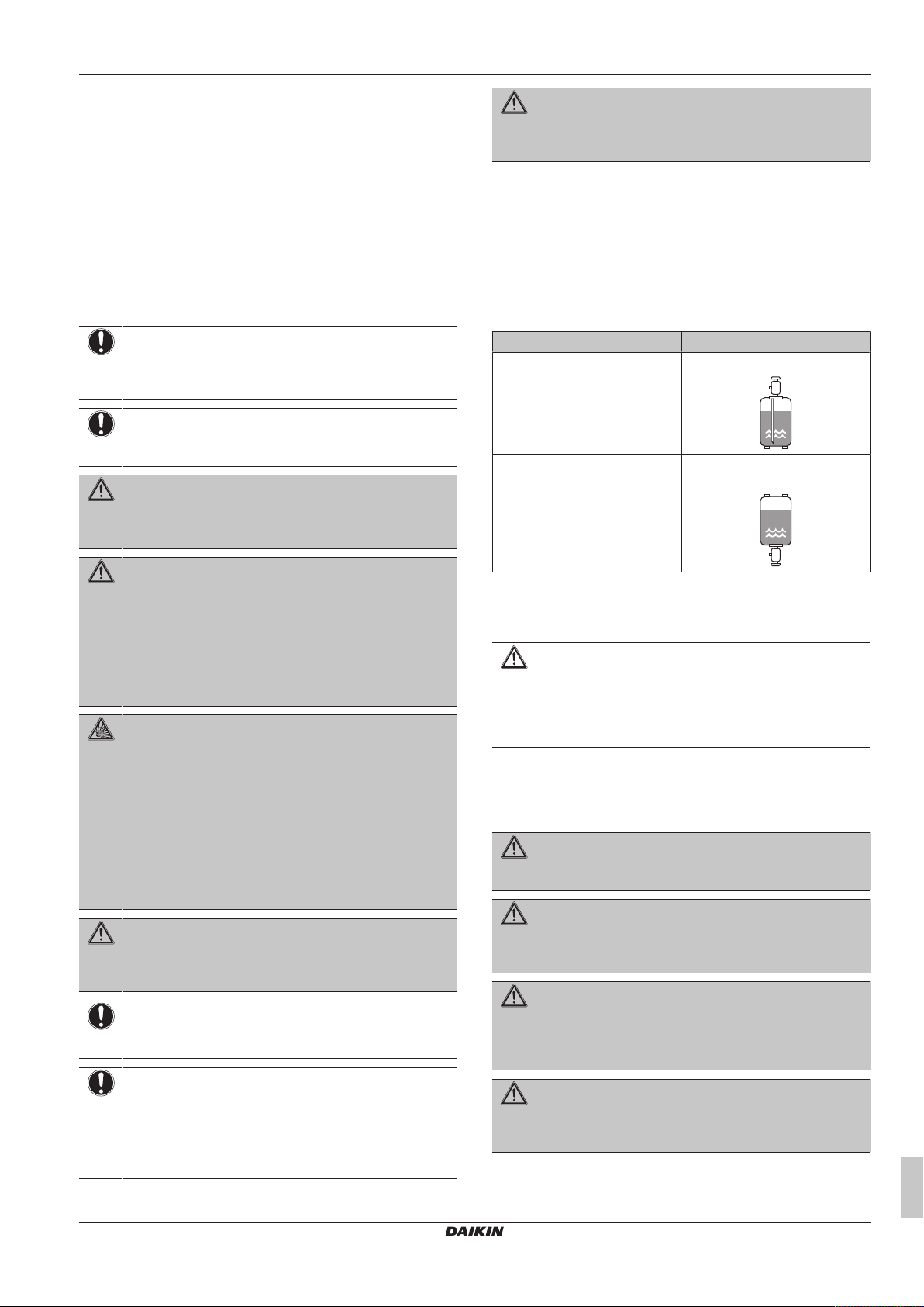
▪ Charge the liquid refrigerant as follows:
If Then
A siphon tube is present
(i.e., the cylinder is marked with
"Liquid filling siphon attached")
A siphon tube is NOT present Charge with the cylinder upside
Charge with the cylinder upright.
down.
WARNING
Take sufficient precautions in case of refrigerant leakage. If
refrigerant gas leaks, ventilate the area immediately.
Possible risks:
▪ Excessive refrigerant concentrations in a closed room
can lead to oxygen deficiency.
▪ Toxic gas may be produced if refrigerant gas comes
into contact with fire.
DANGER: RISK OF EXPLOSION
Pump down – Refrigerant leakage. If you want to pump
down the system, and there is a leak in the refrigerant
circuit:
▪ Do NOT use the unit's automatic pump down function,
with which you can collect all refrigerant from the
system into the outdoor unit. Possible consequence:
Self-combustion and explosion of the compressor
because of air going into the operating compressor.
▪ Use a separate recovery system so that the unit's
compressor does NOT have to operate.
WARNING
ALWAYS recover the refrigerant. Do NOT release them
directly into the environment. Use a vacuum pump to
evacuate the installation.
NOTICE
After all the piping has been connected, make sure there is
no gas leak. Use nitrogen to perform a gas leak detection.
NOTICE
▪ To avoid compressor breakdown, do NOT charge more
than the specified amount of refrigerant.
▪ When the refrigerant system is to be opened,
refrigerant MUST be treated according to the applicable
legislation.
▪ Open refrigerant cylinders slowly.
▪ Charge the refrigerant in liquid form. Adding it in gas form may
prevent normal operation.
CAUTION
When the refrigerant charging procedure is done or when
pausing, close the valve of the refrigerant tank
immediately. If the valve is NOT closed immediately,
remaining pressure might charge additional refrigerant.
Possible consequence: Incorrect refrigerant amount.
1.3.4 Brine
If applicable. See the installation manual or installer reference guide
of your application for more information.
WARNING
The selection of the brine MUST be in accordance with the
applicable legislation.
WARNING
Take sufficient precautions in case of brine leakage. If
brine leaks, ventilate the area immediately and contact
your local dealer.
WARNING
The ambient temperature inside the unit can get much
higher than that of the room, e.g. 70°C. In case of a brine
leak, hot parts inside the unit can create a hazardous
situation.
WARNING
The use and installation of the application MUST comply
with the safety and environmental precautions specified in
the applicable legislation.
SERHQ020~032BAW1 + SEHVX20~64BAW
Split packaged air-cooled water chiller
4P508020-1C – 2019.11
Installer and user reference guide
5
2 About the documentation
1.3.5 Water
If applicable. See the installation manual or installer reference guide
of your application for more information.
NOTICE
Make sure water quality complies with EU directive
98/83EC.
1.3.6 Electrical
DANGER: RISK OF ELECTROCUTION
▪ Turn OFF all power supply before removing the
switch box cover, connecting electrical wiring or
touching electrical parts.
▪ Disconnect the power supply for more than 1 minute,
and measure the voltage at the terminals of main circuit
capacitors or electrical components before servicing.
The voltage MUST be less than 50 V DC before you
can touch electrical components. For the location of the
terminals, see the wiring diagram.
▪ Do NOT touch electrical components with wet hands.
▪ Do NOT leave the unit unattended when the service
cover is removed.
WARNING
If NOT factory installed, a main switch or other means for
disconnection, having a contact separation in all poles
providing full disconnection under overvoltage category III
condition, MUST be installed in the fixed wiring.
WARNING
▪ ONLY use copper wires.
▪ Make sure the field wiring complies with the applicable
legislation.
▪ All field wiring MUST be performed in accordance with
the wiring diagram supplied with the product.
▪ NEVER squeeze bundled cables and make sure they
do NOT come in contact with the piping and sharp
edges. Make sure no external pressure is applied to the
terminal connections.
▪ Make sure to install earth wiring. Do NOT earth the unit
to a utility pipe, surge absorber, or telephone earth.
Incomplete earth may cause electrical shock.
▪ Make sure to use a dedicated power circuit. NEVER
use a power supply shared by another appliance.
▪ Make sure to install the required fuses or circuit
breakers.
▪ Make sure to install an earth leakage protector. Failure
to do so may cause electric shock or fire.
▪ When installing the earth leakage protector, make sure
it is compatible with the inverter (resistant to high
frequency electric noise) to avoid unnecessary opening
of the earth leakage protector.
CAUTION
When connecting the power supply, the earth connection
must be made before the current-carrying connections are
established. When disconnecting the power supply, the
current-carrying connections must be separated before the
earth connection is. The length of the conductors between
the power supply stress relief and the terminal block itself
must be as such that the current-carrying wires are
tautened before the earth wire is in case the power supply
is pulled loose from the stress relief.
NOTICE
Precautions when laying power wiring:
▪ Do NOT connect wiring of different thicknesses to the
power terminal block (slack in the power wiring may
cause abnormal heat).
▪ When connecting wiring which is the same thickness,
do as shown in the figure above.
▪ For wiring, use the designated power wire and connect
firmly, then secure to prevent outside pressure being
exerted on the terminal board.
▪ Use an appropriate screwdriver for tightening the
terminal screws. A screwdriver with a small head will
damage the head and make proper tightening
impossible.
▪ Over-tightening the terminal screws may break them.
Install power cables at least 1 m away from televisions or radios to
prevent interference. Depending on the radio waves, a distance of
1m may not be sufficient.
WARNING
▪ After finishing the electrical work, confirm that each
electrical component and terminal inside the electrical
components box is connected securely.
▪ Make sure all covers are closed before starting up the
unit.
NOTICE
Only applicable if the power supply is three‑phase, and the
compressor has an ON/OFF starting method.
If there exists the possibility of reversed phase after a
momentary black out and the power goes on and off while
the product is operating, attach a reversed phase
protection circuit locally. Running the product in reversed
phase can break the compressor and other parts.
2 About the documentation
2.1 About this document
INFORMATION
Make sure that the user has the printed documentation and
ask him/her to keep it for future reference.
Target audience
Authorised installers + end users
INFORMATION
This appliance is intended to be used by expert or trained
users in shops, in light industry and on farms, or for
commercial use by lay persons.
Documentation set
This document is part of a documentation set. The complete set
consists of:
▪ General safety precautions:
▪ Safety instructions that you must read before installing
▪ Format: Paper (in the box of the outdoor unit)
Installer and user reference guide
6
SERHQ020~032BAW1 + SEHVX20~64BAW
Split packaged air-cooled water chiller
4P508020-1C – 2019.11
3 About the box
b
a
▪ Installation and operation manual:
▪ Installation and operation instructions
▪ Format: Paper (in the box of the indoor unit)
▪ Installer and user reference guide:
▪ Preparation of the installation, reference data,…
▪ Detailed step-by-step instructions and background information
for basic and advanced usage
▪ Format: Digital files on http://www.daikineurope.com/support-
and-manuals/product-information/
Latest revisions of the supplied documentation may be available on
the regional Daikin website or via your dealer.
The original documentation is written in English. All other languages
are translations.
Technical engineering data
▪ A subset of the latest technical data is available on the regional
Daikin website (publicly accessible).
▪ The full set of latest technical data is available on the Daikin
Business Portal (authentication required).
For installation of the heat pump unit (location, piping, and wiring),
refer to the installation and operation manual of the RXYQ*.
INFORMATION
First read the indoor unit manual, and only then the
outdoor unit manual.
2.2 Installer and user reference guide at a glance
Chapter Description
General safety
precautions
About the documentation What documentation exists for the
About the box How to unpack the units and remove
About the units and
options
Preparation What to do and know before going
Installation What to do and know to install the
Configuration What to do and know to configure the
Operation Operation of the units
Commissioning What to do and know to commission the
Hand‑over to the user What to give and explain to the user
Maintenance and service How to maintain and service the units
Troubleshooting What to do in case of problems
Disposal How to dispose of the system
Technical data Specifications of the system
Field settings table Table to be filled in by the installer, and
Glossary Definition of terms
Safety instructions that you must read
before installing
installer
their accessories
▪ How to identify the units
▪ Possible combinations of units and
options
on‑site
system
system after it is installed
system after it is configured
kept for future reference
For the installer
3 About the box
3.1 Overview: About the box
This chapter describes what you have to do after the boxes with the
outdoor and indoor unit are delivered on-site.
Keep the following in mind:
▪ At delivery, the unit MUST be checked for damage. Any damage
MUST be reported immediately to the claims agent of the carrier.
▪ Bring the packed unit as close as possible to its final installation
position to prevent damage during transport.
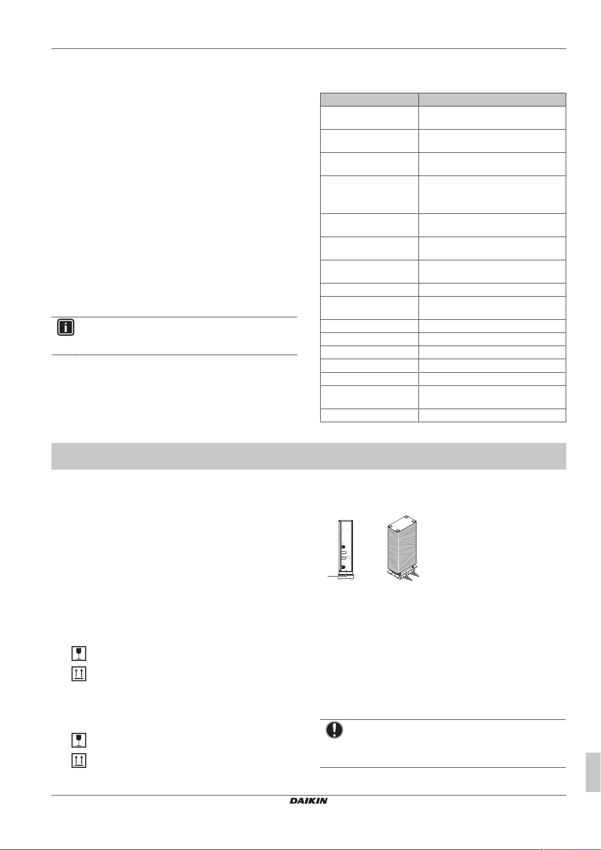
▪ When handling the unit, take into account the following:
Fragile, handle the unit with care.
Keep the unit upright in order to avoid compressor
damage.
▪ Prepare the path along which you want to bring the unit inside in
advance.
▪ When handling the unit, take into account the following:
Fragile, handle the unit with care.
Keep the unit upright in order to avoid compressor
damage.
▪ Prepare the path along which you want to bring the unit inside in
advance.
a Opening
b Forklift
▪ A forklift can only be used for transport as long as the unit remains
on its pallet as shown above.
▪ A forklift can only be used for transport as long as the unit remains
on its pallet as shown above.
▪ If a forklift is to be used, preferably transport the unit with pallet
first, then pass the forklift arms through the large rectangular
openings on the bottom of the unit.
▪ Once at final position, unpack the unit and pass the forklift arms
through the large rectangular openings on the bottom of the unit.
NOTICE
Cover the forklift arms with a cloth to prevent damaging the
unit. If the paint on the bottom frame peels off, the anticorrosion effect may decrease.
SERHQ020~032BAW1 + SEHVX20~64BAW
Split packaged air-cooled water chiller
4P508020-1C – 2019.11
Installer and user reference guide
7
3 About the box
1 2
a
d e
c
b
d
a
a
c
b
c
b
c
b
c
f
f
1× 1× 1× 1×1× 1× 1×
ea c d f g
b
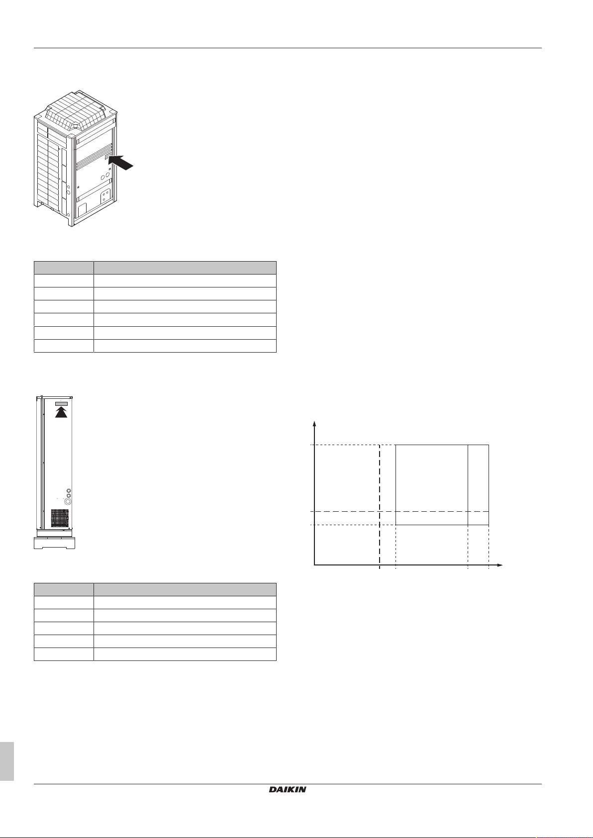
3.2 Outdoor unit
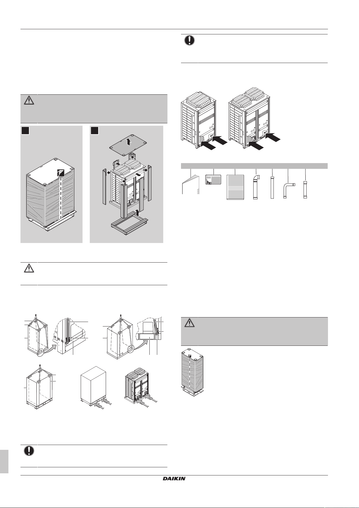
3.2.1 To unpack the outdoor unit
Remove the packaging material from the unit:
▪ Take care not to damage the unit when removing the shrink foil
with a cutter.
▪ Remove the 4 bolts fixing the unit to its pallet.
WARNING
Tear apart and throw away plastic packaging bags so that
nobody, especially children, can play with them. Possible
risk: suffocation.
NOTICE
Cover the forklift arms with a cloth to prevent damaging the
unit. If the paint on the bottom frame peels off, the anticorrosion effect may decrease.
3.2.3 To remove the accessories from the outdoor unit
Make sure that all accessories are available in the unit.
a General safety precautions
b Fluorinated greenhouse gases label
c Multilingual fluorinated greenhouse gases label
d Gas side accessory pipe
e Gas side accessory pipe
f Liquid side accessory pipe
g Liquid side accessory pipes
3.2.2 To handle the outdoor unit
CAUTION
To avoid injury, do NOT touch the air inlet or aluminium
fins of the unit.
▪ Lift the unit preferably with a crane and 2belts of at least 8m long
as shown in the figure below. Always use protectors to prevent
belt damage and pay attention to the position of the unit's centre
of gravity.
Installer and user reference guide
8
a Packaging material
b Belt sling
c Protector
d Large opening
e Small opening (40×45)
f Forklift
NOTICE
Use a belt sling of ≤20mm wide that adequately bears the
weight of the unit.
3.3 Indoor unit
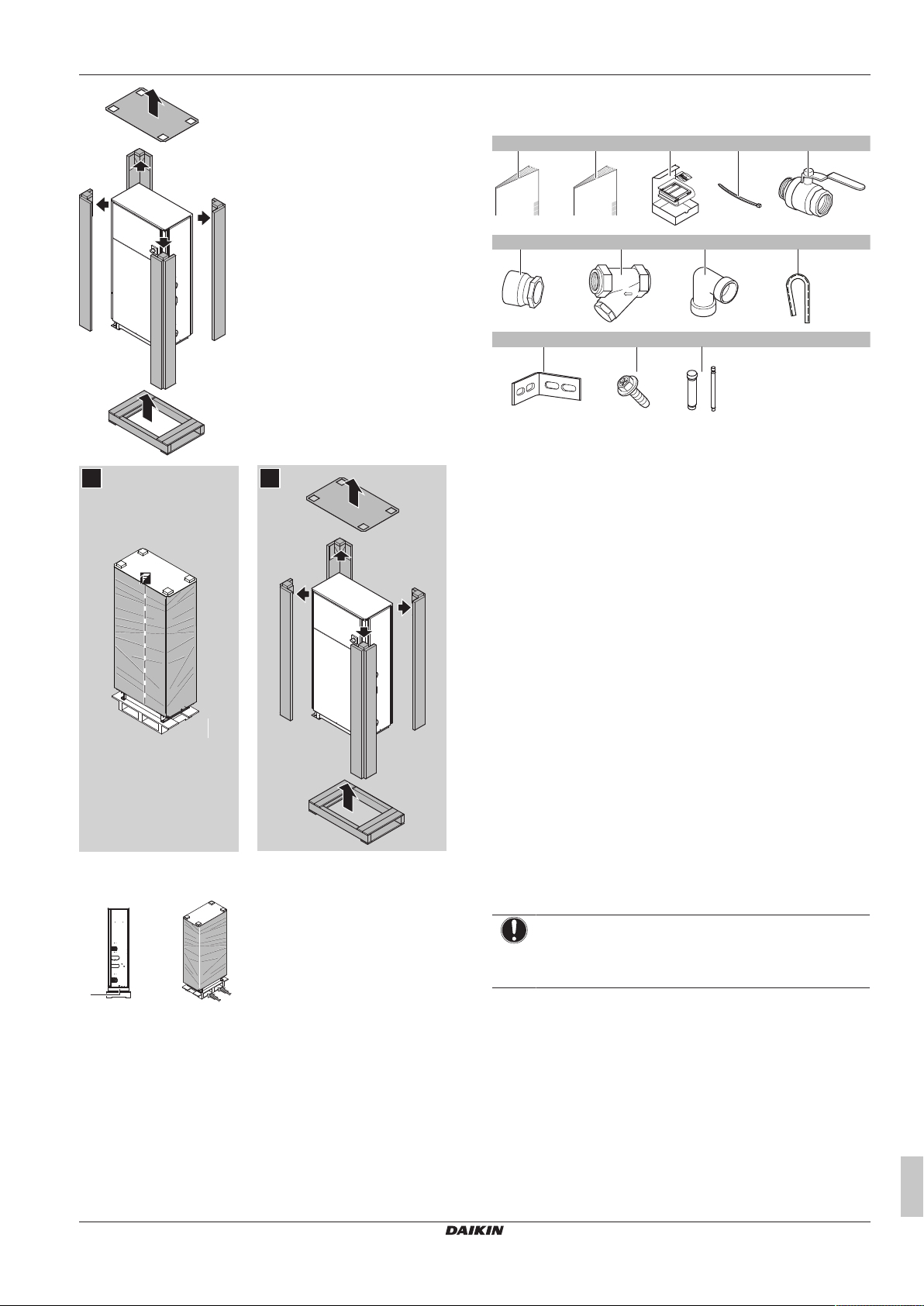
3.3.1 To unpack the indoor unit
Remove the packaging material from the unit:
▪ Take care not to damage the unit when removing the shrink foil
with a cutter.
▪ Remove the 4 bolts fixing the unit to its pallet.
▪ Take care not to drop the unit when removing it from the pallet. Lift
the unit with at least 2installers.
WARNING
Tear apart and throw away plastic packaging bags so that
nobody, especially children, can play with them. Possible
risk: suffocation.
SERHQ020~032BAW1 + SEHVX20~64BAW
Split packaged air-cooled water chiller
4P508020-1C – 2019.11
4 About the units and options
1 2
b
a
8×
a d ec
1×
b
1× 1×
f g
h
2×
1× 1×1×/2×
i
2×
j k
3×2×
l
2×
3.3.3 To remove the accessories from the indoor unit
a General safety precautions
b Installation manual and operation manual (panel 3)
c User interface (panel 3)
d Tie wraps (panel 3)
e Shut-off valves (panel 3)
f Threaded connection (panel 3) (1× for SEHVX20+32BAW,
2× for SEHVX40+64BAW)
g Filter (panel 3)
h Elbow (panel 3)
i Black grommet (2×)
j L-shaped support (2×)
k M5 screws (3×)
l Accessory pipes (Ø12.7→Ø9.52 and Ø25.4→Ø28.6)
3.3.2 To handle the indoor unit
a Opening
▪ A forklift can only be used for transport as long as the unit remains
on its pallet as shown above.
b Forklift
4 About the units and options
4.1 Overview: About the units and options
This chapter contains information about:
▪ Identifying the outdoor unit
▪ Identifying the indoor unit
▪ About the outdoor unit
▪ About the indoor unit
▪ Combining the split system with options
▪ Where the outdoor and indoor units fit in the system layout
4.2 Identification
NOTICE
When installing or servicing several units at the same time,
make sure NOT to switch the service panels between
different models.
SERHQ020~032BAW1 + SEHVX20~64BAW
Split packaged air-cooled water chiller
4P508020-1C – 2019.11
Installer and user reference guide
9
4 About the units and options
43
–5
0
0 5 20 25
LWE
T
A
A B
4.2.1 Identification label: Outdoor unit
Location
Model identification
Example: SE RH Q 020 BA W1
Code Explanation
SE Special European model
RH Outdoor/low water temperature
Q R410A refrigerant
020 Capacity class
BA Model series
W1 Power supply: 3P, 400V
4.2.2 Identification label: Indoor unit
4.2.4 About the indoor unit
This installation manual concerns the inverter heat pump chilling unit
with separate hydro module. The unit is intended for indoor
installation and can be combined with VRV outdoor units
(SERHQ020+032BAW1) for air conditioning purposes, or it can be
used for supplying water for process cooling applications.
The units are available in 4 standard sizes with nominal capacities
ranging from 16.8 to 63 kW.
The unit is designed to work in heating mode at ambient
temperatures from –15°C to 35°C and in cooling mode at ambient
temperatures from –5°C to 43°C.
The main component is the water heat exchanger.
The indoor unit is connected to the outdoor unit by field refrigerant
piping and the compressor in the outdoor unit circulates refrigerant
into the heat exchangers.
▪ In cooling mode, the refrigerant transports the heat taken from the
water heat exchanger to the air heat exchanger where the heat is
released to the air.
▪ In heating mode, the refrigerant transports the heat taken from the
air heat exchanger to the water heat exchanger where the heat is
released to the water.
4.2.5 About combining units and options
This packaged air-cooled water chiller can be combined with fan coil
units and is intended for R410A use only.
The indoor unit can be combined with fan coil units and is intended
for R410A use only.
Location
Model identification
Example: SE HVX 20 BA W
Code Explanation
SE Special European model
HVX Indoor unit / Floor-standing
20 Capacity class
BA Model series
W Power supply: 3P, 400V
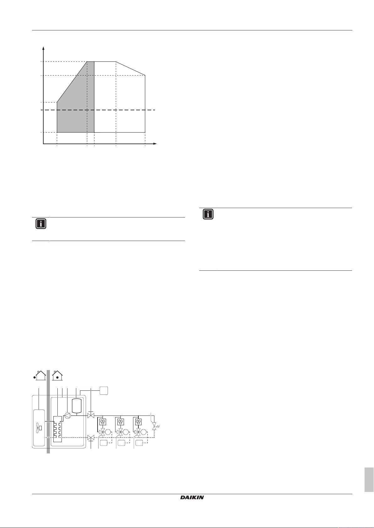
4.2.6 Operation range
Cooling
TAAmbient temperature (°CDB)
LWE Leaving water evaporator temperature (°C)
A Standard water operation range
B Pull down area
4.2.3 About the outdoor unit
SERHQ outdoor units are designed for outdoor installation and are
meant to be combined with SEHVX indoor units.
The outdoor units are designed to work in heating mode at ambient
temperatures from –15°C WB to 35°C WB and in cooling mode at
ambient temperatures from –5°CDB to 43°CDB.
Installer and user reference guide
10
SERHQ020~032BAW1 + SEHVX20~64BAW
Split packaged air-cooled water chiller
4P508020-1C – 2019.11
5 Preparation
0
35
25
5
–15
5 (EWC) 20 25 35 50
LWC
T
A
A B
RC
RT1M1RT2M2RT3
M3
FC1 FC2 FC3
a c e f
f
g g g
h
db
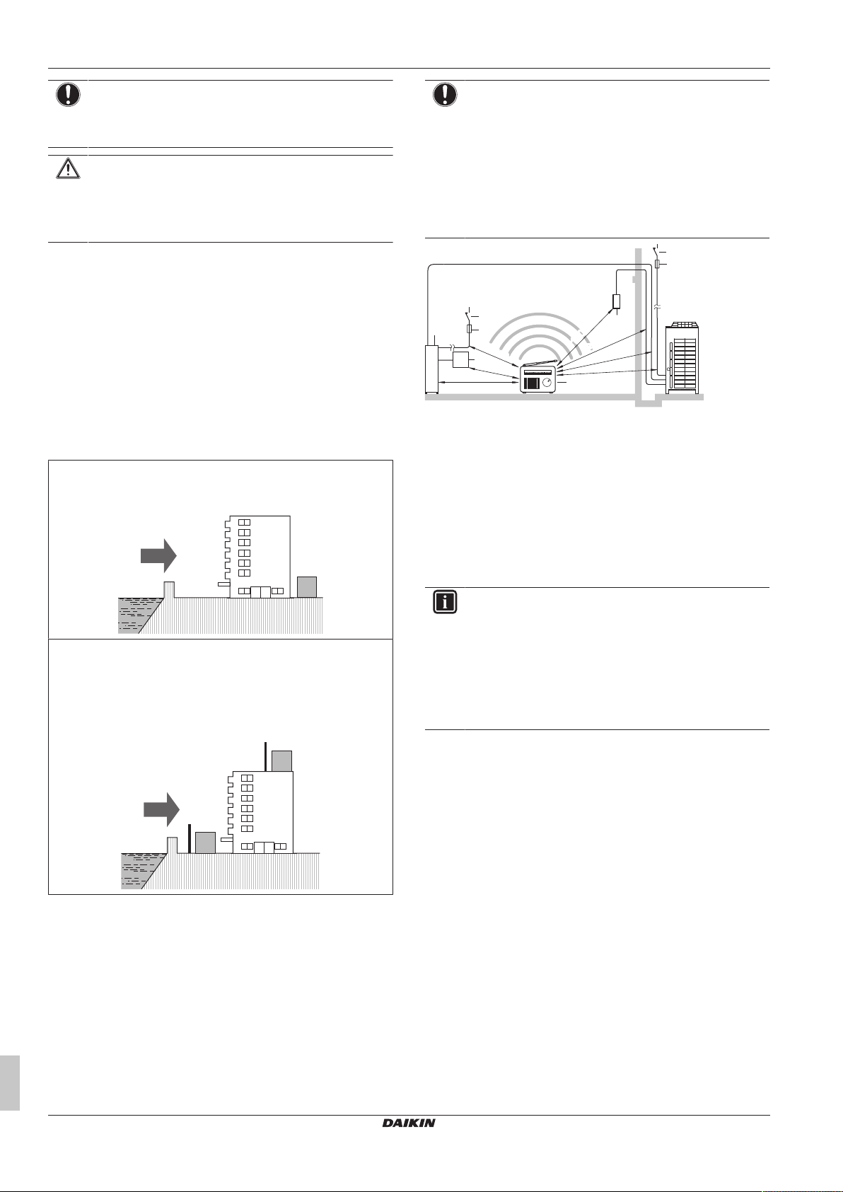
Heating
TAAmbient temperature (°CDB)
LWC Leaving water condenser temperature (°C)
EWC Entering water condenser temperature (°C)
A Pull up area
B Standard water operation range
4.3 Combining units and options
4.3.1 Possible options for the split system
INFORMATION
Refer to the technical engineering data for the latest option
names.
Remote controller (EKRUAHTB)
A second remote controller to control the unit from 2 locations.
Demand PCB (EKRP1AHTA)
To enable the power saving consumption control by digital inputs
you must install the demand PCB.
For installation instructions, see the installation manual of the
demand PCB. In case of SEHVX40+64BAW, 2 sets of this option
are required.
External control adaptor (DTA104A62)
To instruct specific operation with an external input coming from a
central control, the external control adaptor can be used. Instructions
(group or individual) can be given for low noise operation and power
consumption limitation operation. In case of SEHVX40+64BAW, 2
sets of this option are required.
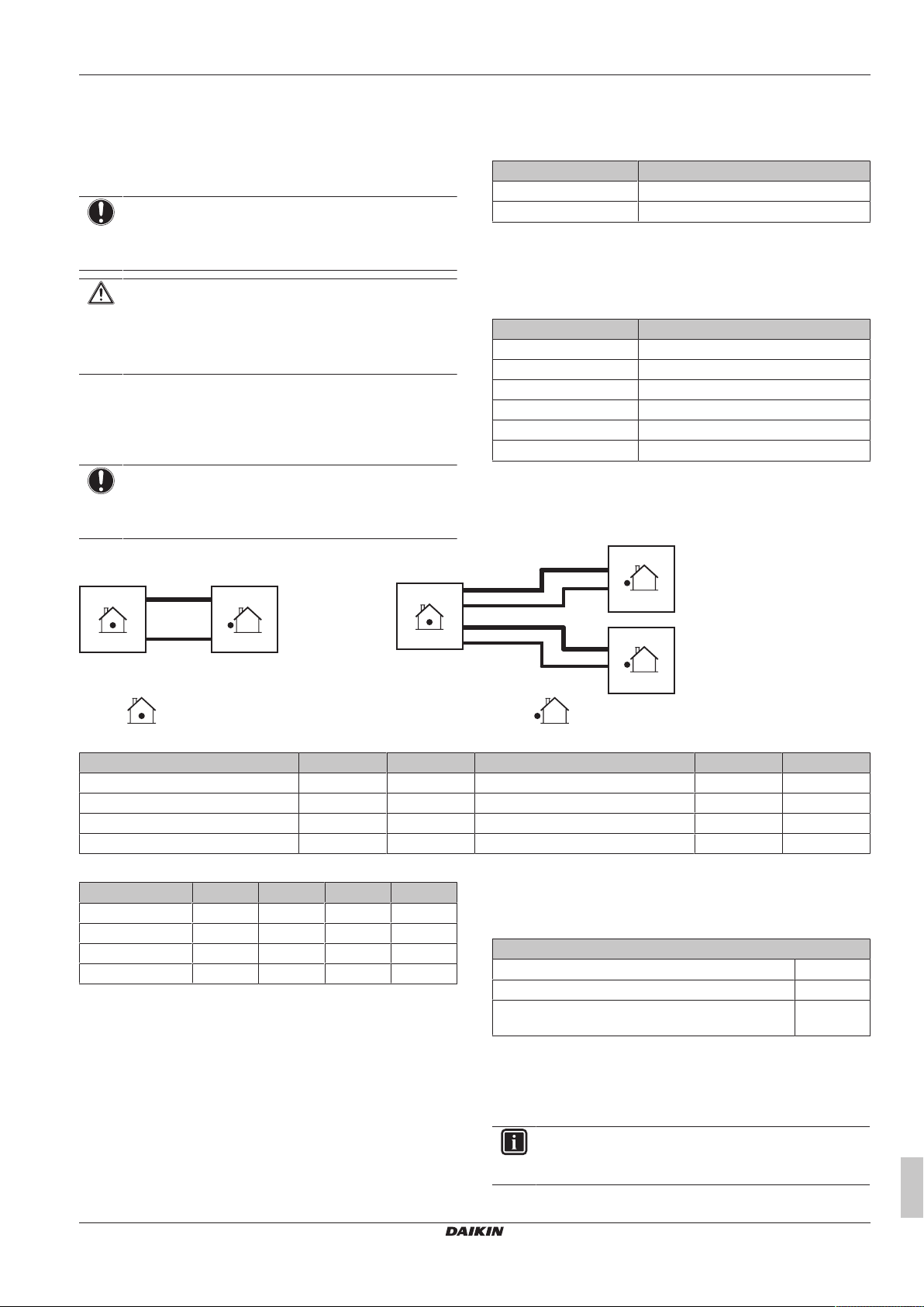
4.4 System layout
SERHQ020~032BAW1 + SEHVX20~64BAW
Split packaged air-cooled water chiller
4P508020-1C – 2019.11
a Outdoor unit
b Indoor unit
c Plate heat exchanger
d Pump
e Expansion vessel
f Shut-off valve
g Motorized valve
h Bypass valve
FC1…3 Fancoil unit (field supply)
RC User interface
RT1…3 Room thermostat
5 Preparation
5.1 Overview: Preparation
This chapter describes what you have to do and know before going
on-site.
It contains information about:
▪ Preparing the installation site
▪ Preparing the refrigerant piping
▪ Preparing the water piping
▪ Preparing the electrical wiring
5.2 Preparing the installation site
5.2.1 Installation site requirements of the outdoor unit
INFORMATION
Also read the following requirements:
▪ General installation site requirements. See the
"General safety precautions" chapter.
▪ Service space requirements. See the "Technical data"
chapter.
▪ Refrigerant piping requirements (length, height
difference). See further in this "Preparation" chapter.
▪ Provide sufficient space around the unit for servicing and air
circulation.
▪ Make sure the installation site withstands the weight and vibration
of the unit.
▪ Make sure the unit is level.
▪ Select a place where rain can be avoided as much as possible.
▪ Take care that in the event of a water leak, water cannot cause
any damage to the installation space and surroundings.
▪ Select the location of the unit in such a way that the sound
generated by the unit does not disturb anyone, and the location is
selected according the applicable legislation.
▪ During installation, avoid the possibility that anybody can climb on
the unit or place objects on the unit.
▪ All piping lengths and distances have been taken into
consideration (see "5.3.3About the piping length"[413]).
Do NOT install the unit in the following places:
▪ In potentially explosive atmospheres.
▪ In places where there is machinery that emits electromagnetic
waves. Electromagnetic waves may disturb the control system,
and cause malfunction of the equipment.
▪ In places where there is a risk of fire due to the leakage of
flammable gases (example: thinner or gasoline), carbon fibre,
ignitable dust.
▪ In places where corrosive gas (example: sulphurous acid gas) is
produced. Corrosion of copper pipes or soldered parts may cause
the refrigerant to leak.
▪ In places where a mineral oil mist, spray or vapour may be
present in the atmosphere. Plastic parts may deteriorate and fall
off or cause water leakage.
Installer and user reference guide
11
5 Preparation
b
c
a
a
b
c
d
c
d
≥1500
≥1500
a
d
e
b
(mm)
f
c
≥1000≥1000
≥1000
≥1500
≥1500
≥1000
b
c
≥1500≥1500
NOTICE
This is a class A product. In a domestic environment this
product may cause radio interference in which case the
user may be required to take adequate measures.
CAUTION
Appliance NOT accessible to the general public, install it in
a secured area, protected from easy access.
This unit is suitable for installation in a commercial and
light industrial environment.
▪ When installing, take strong winds, typhoons or earthquakes into
account, improper installation may result in the unit turning over.
▪ Be sure that the air inlet and outlet of the unit is not positioned
towards the main wind direction. Frontal wind will disturb the
operation of the unit. If necessary, use a screen to block the wind.
▪ Ensure that water cannot cause any damage to the location by
adding water drains to the foundation and prevent water traps in
the construction.
▪ In heavy snowfall areas, select an installation site where snow will
not affect the operation of the unit.
Seaside installation. Make sure the outdoor unit is NOT directly
exposed to sea winds. This is to prevent corrosion caused by high
levels of salt in the air, which might shorten the life of the unit.
Install the outdoor unit away from direct sea winds.
Example: Behind the building.
NOTICE
The equipment described in this manual may cause
electronic noise generated from radio-frequency energy.
The equipment complies to specifications that are
designed to provide reasonable protection against such
interference. However, there is no guarantee that
interference will not occur in a particular installation.
It is therefore recommended to install the equipment and
electric wires keeping proper distances away from stereo
equipment, personal computers, etc.
a Personal computer or radio
b Fuse
c Earth leakage breaker
d Cool/heat selector
e User interface
f Indoor unit
▪ In places with weak reception, keep distances of 3m or more to
avoid electromagnetic disturbance of other equipment and use
conduit tubes for power and transmission lines.
If the outdoor unit is exposed to direct sea winds, install a
windbreaker.
▪ Height of windbreaker≥1.5×height of outdoor unit
▪ Mind the service space requirements when installing the
windbreaker.
a Sea wind
b Building
c Outdoor unit
d Windbreaker
Installer and user reference guide
12
5.2.2 Installation site requirements of the indoor unit
INFORMATION
Also read the following requirements:
▪ General installation site requirements. See the
"General safety precautions" chapter.
▪ Service space requirements. See the "Technical data"
chapter.
▪ Refrigerant piping requirements (length, height
difference). See further in this "Preparation" chapter.
▪ Provide sufficient space around the unit for servicing and air
circulation.
▪ Make sure the installation site withstands the weight and vibration
of the unit.
▪ Make sure the unit is level.
▪ Select the location of the unit in such a way that the sound
generated by the unit does not disturb anyone, and the location is
selected according the applicable legislation.
▪ Take care that in the event of a water leak, water cannot cause
any damage to the installation space and surroundings.
▪ During installation, avoid the possibility that anybody can climb on
the unit or place objects on the unit.
▪ All piping lengths and distances have been taken into
consideration (see "5.3.3About the piping length"[413]).
Do NOT install the unit in the following places:
▪ In potentially explosive atmospheres.
▪ In places where there is machinery that emits electromagnetic
waves. Electromagnetic waves may disturb the control system,
and cause malfunction of the equipment.
▪ In places where there is a risk of fire due to the leakage of
flammable gases (example: thinner or gasoline), carbon fibre,
ignitable dust.
SERHQ020~032BAW1 + SEHVX20~64BAW
Split packaged air-cooled water chiller
4P508020-1C – 2019.11
5 Preparation
G
L
G1
L2
G2
L1
1
2
▪ In places where corrosive gas (example: sulphurous acid gas) is
produced. Corrosion of copper pipes or soldered parts may cause
the refrigerant to leak.
▪ In places where a mineral oil mist, spray or vapour may be
present in the atmosphere. Plastic parts may deteriorate and fall
off or cause water leakage.
NOTICE
This is a class A product. In a domestic environment this
product may cause radio interference in which case the
user may be required to take adequate measures.
CAUTION
Appliance NOT accessible to the general public, install it in
a secured area, protected from easy access.
This unit is suitable for installation in a commercial and
light industrial environment.
5.3 Preparing refrigerant piping
5.3.1 Refrigerant piping requirements
NOTICE
The piping and other pressure-containing parts shall be
suitable for refrigerant. Use phosphoric acid deoxidised
seamless copper for refrigerant.
▪ Foreign materials inside pipes (including oils for fabrication) must
be ≤30mg/10m.
▪ Temper grade: use piping with temper grade in function of the
pipe diameter as listed in table below.
Pipe Ø Temper grade of piping material
≤15.9mm O (annealed)
≥19.1mm 1/2H (half hard)
▪ All piping lengths and distances have been taken into
consideration (see "5.3.3About the piping length"[413]).
▪ The pipe thickness of the refrigerant piping shall comply with the
applicable legislation. The minimal pipe thickness for R410A
piping must be in accordance with the table below.
Pipe Ø Minimal thickness t
6.4mm/9.5mm/12.7mm 0.80mm
15.9mm 0.99mm
19.1mm/22.2mm 0.80mm
28.6mm 0.99mm
34.9mm 1.21mm
41.3mm 1.43mm
5.3.2 To select the piping size
Determine the proper size using the following tables and reference
figure (only for indication).
Indoor unit Outdoor unit
▪ Piping connection sizes
Indoor unit Gas Liquid Outdoor unit Gas Liquid
SEHVX20BAW Ø25.4mm Ø12.7mm 1× SERHQ020BAW1 Ø22.2mm Ø9.52mm
SEHVX32BAW Ø25.4mm Ø12.7mm 1× SERHQ032BAW1 Ø28.6mm Ø12.7mm
SEHVX40BAW Ø25.4mm Ø12.7mm 2× SERHQ020BAW1 Ø22.2mm Ø9.52mm
SEHVX64BAW Ø25.4mm Ø12.7mm 2× SERHQ032BAW1 Ø28.6mm Ø12.7mm
▪ Field piping sizes
Indoor unit G/G1 L/L1 G2 L2
SEHVX20BAW Ø28.6mm Ø9.52mm — —
SEHVX32BAW Ø28.6mm Ø12.7mm — —
SEHVX40BAW Ø28.6mm Ø9.52mm Ø28.6mm Ø9.52mm
SEHVX64BAW Ø28.6mm Ø12.7mm Ø28.6mm Ø12.7mm
If the hydro module connections do not match the diameter of the
specified piping requirements, the piping diameter requirements
must be met using reducers/expanders (field supply) on the hydro
module connections.
If the indoor unit connections do not match the diameter of the
specified piping requirements, the piping diameter requirements
must be met using reducers/expanders (field supply) on the indoor
unit connections.
Other diameters (mm sizes) can also be used if the required pipe
sizes (inch sizes) are not available, taking the following into account:
▪ select the pipe size nearest to the required size,
SERHQ020~032BAW1 + SEHVX20~64BAW
Split packaged air-cooled water chiller
4P508020-1C – 2019.11
▪ use the suitable adapters for the change-over from inch to mm
pipes (field supply).
5.3.3 About the piping length
Maximum piping length and height difference
Maximum allowable piping length 30m
Height difference between indoor and outdoor unit <10m
Height difference between outdoor unit 1 and outdoor
unit 2 (if applicable)
0m
5.4 Preparing water piping
5.4.1 Water circuit requirements
INFORMATION
Also read the precautions and requirements in the
"General safety precautions" chapter.
Installer and user reference guide
13
5 Preparation
a
b
a
c
d
b
NOTICE
In case of plastic pipes, make sure they are fully oxygen
diffusion tight according to DIN 4726. The diffusion of
oxygen into the piping can lead to excessive corrosion.
▪ Connecting piping – Legislation. Make all piping connections in
accordance with the applicable legislation and the instructions in
the "Installation" chapter, respecting the water inlet and outlet.
▪ Connecting piping – Force. Do NOT use excessive force when
connecting the piping. Deformation of the piping can cause
malfunctioning of the unit.
▪ Connecting piping – Tools. Only use appropriate tooling to
handle brass, which is a soft material. If NOT, pipes will get
damaged.
▪ Connecting piping – Air, moisture, dust. If air, moisture or dust
gets into the circuit, problems may occur. To prevent this:
▪ Only use clean pipes
▪ Hold the pipe end downwards when removing burrs.
▪ Cover the pipe end when inserting it through a wall, to prevent
dust and/or particles from entering the pipe.
▪ Use a decent thread sealant to seal connections.
Capacity class Minimum required flow rate
20 23 l/min
32 36 l/min
40 46 l/min
64 72 l/min
▪ Field supply components – Water pressure and temperature.
Check that all components in the field piping can withstand the
water pressure and water temperature.
▪ Drainage – Low points. Provide drain taps at all low points of the
system in order to allow complete drainage of the water circuit.
▪ Non-brass metallic piping. When using non-brass metallic
piping, insulate the brass and non-brass properly so that they do
NOT make contact with each other. This to prevent galvanic
corrosion.
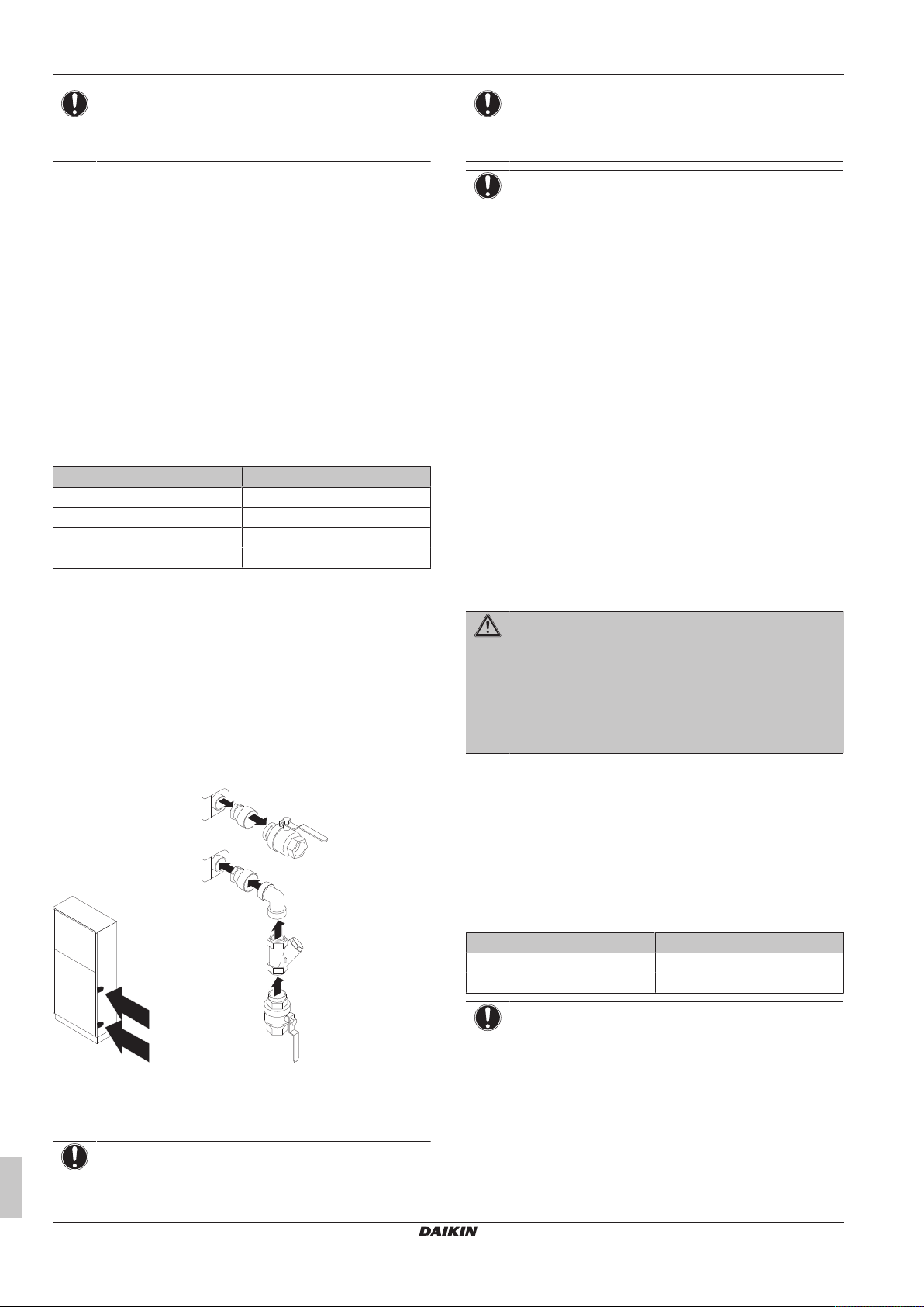
▪ Shut-off valves. Two shut-off valves are delivered with the unit.
Install them as shown in the following figure.
NOTICE
If the bend is not used during installation, replace it with an
extension (5cm long for a 1¼"filter, and 6 cm long for a
2"filter) to ensure proper cleaning operation of the filter.
NOTICE
Be sure to install the filter properly. Failure to install or
incorrect installation will damage the plate heat exchanger
permanently.
▪ Drain taps. Drain taps must be provided at all low points of the
system to permit complete drainage of the circuit. A drain valve is
provided inside the unit.
▪ Air vents. Provide air vents at all high points of the system, which
must also be easily accessible for servicing. An automatic air
purge valve is provided inside the unit. Check that this air purge
valve is NOT tightened too much, so that automatic release of air
from the water circuit is possible. Refer to field setting[E‑04] in
Field settings on the remote controller.
▪ Air vents. Provide air vents at all high points of the system, which
must also be easily accessible for servicing. An automatic air
purge valve is provided inside the unit. Check that this air purge
valve is NOT tightened too much, so that automatic release of air
from the water circuit is possible. Refer to field setting[E‑04] in
"7.2.9Field settings on the user interface"[435].
▪ Water pressure. Take care that the components installed in the
field piping can withstand the water pressure (maximum 3 bar +
static pressure of the pump). Refer to ESP curve: Outdoor unit.
▪ Water pressure. Take care that the components installed in the
field piping can withstand the water pressure (maximum 3 bar +
static pressure of the pump). Refer to ESP curve: Indoor unit.
WARNING
▪ For correct operation of the system, a regulating valve
must be installed in the water system. The regulating
valve is to be used to regulate the water flow in the
system (field supply).
▪ Selecting a flow outside the curves can cause
malfunction or damage to the unit. Also refer to the
Technical specifications.
▪ The maximum water piping temperature is 50°C according to
safety device setting.
▪ Always use materials which are compatible with the water used in
the system and with the materials used in the unit. (The unit piping
fittings are made of brass, the plate heat exchangers are made of
stainless steel 316 plates brazed together with copper and the
optional pump housing is made of cast iron.)
▪ Select the piping diameter in relation to the required water flow
and available external static pressure (ESP) of the pump. See the
following table for the recommended water piping diameter.
Capacity class Water piping diameter
20+32 1-1/4"
40+64 2"
a Adapter piece (on the inlet only in case of
SEHVX40+64BAW)
b Shut-off valve
c Bend
d Filter
NOTICE
Before mounting the bend, attach the filter to it.
Installer and user reference guide
14
NOTICE
It is strongly recommended to install an additional filter on
the water circuit. Especially to remove metallic particles
from the field water piping, it is advised to use a magnetic
or cyclone filter which can remove small particles. Small
particles can damage the unit and will not be removed by
the standard filter of the unit.
SERHQ020~032BAW1 + SEHVX20~64BAW
Split packaged air-cooled water chiller
4P508020-1C – 2019.11
5 Preparation
0.0
0.5
1.0
1.5
2.0
2.5
3.0
3.5
4.0
0 0.5 1 1.5 2 2.5 3 3.5 4 4.5 5 5.5 6 6.5 7 7.5 8 8.5
9
a
b
0
0.5
1
1.5
2
2.5
3
0 50 100 150 200 250 300 350 400 450 500 550 600
A
B
33
b
a
5.4.2 Formula to calculate the expansion vessel pre-pressure
The pre-pressure (Pg) of the vessel depends on the installation
height difference (H):
Pg=0.3+(H/10) (bar)
5.4.3 To check the water volume and expansion vessel pre-pressure
The unit has an expansion vessel of 12 litre with a default prepressure of 1bar.
Minimum water volume
Model Minimum total water volume (l)
20 76
32 110
40 152
64 220
INFORMATION
In critical processes, or in rooms with a high heat load,
extra water might be required.
INFORMATION
The temperature step difference can be modified using
settings [A‑02] and [F‑00]. This has an impact on the
minimum water volume required when the unit operates in
cooling.
By default, the unit is set to have a water temperature
difference of 3.5 K which allows it to operate with the
minimum volume mentioned in the previous table.
However, if a smaller temperature differential is set, as in
the case of process cooling applications where
temperature fluctuations must be avoided, a larger
minimum water volume will be required.
To ensure proper operation of the unit when changing the
values of setting [F‑00] (for cooling mode), the minimum
water volume has to be corrected. If this volume exceeds
the range allowed in the unit, an additional expansion
vessel or a buffer tank must be installed in the field piping.
Example:
To illustrate the impact on the system when modifying the setting
[F‑00], we will consider a unit with a minimum allowable water
volume of 66l. The unit is installed 5m below the highest point in
the water circuit.
Assuming that the setting [F‑00] is changed from 5°C (default value)
to 0°C. From the below table we see that 5°C corresponds to a
temperature differential of 3.5K and 0°C to 1K, which is actually the
lowest value we can set.
[F‑00] value (°C) Temperature differential (K)
0 1
1 1.5
2 2
3 2.5
4 3
5 3.5
6 4
7 4.5
8 5
9 5.5
10 6
11 6.5
SERHQ020~032BAW1 + SEHVX20~64BAW
Split packaged air-cooled water chiller
4P508020-1C – 2019.11
[F‑00] value (°C) Temperature differential (K)
12 7
13 7.5
14 8
15 8.5
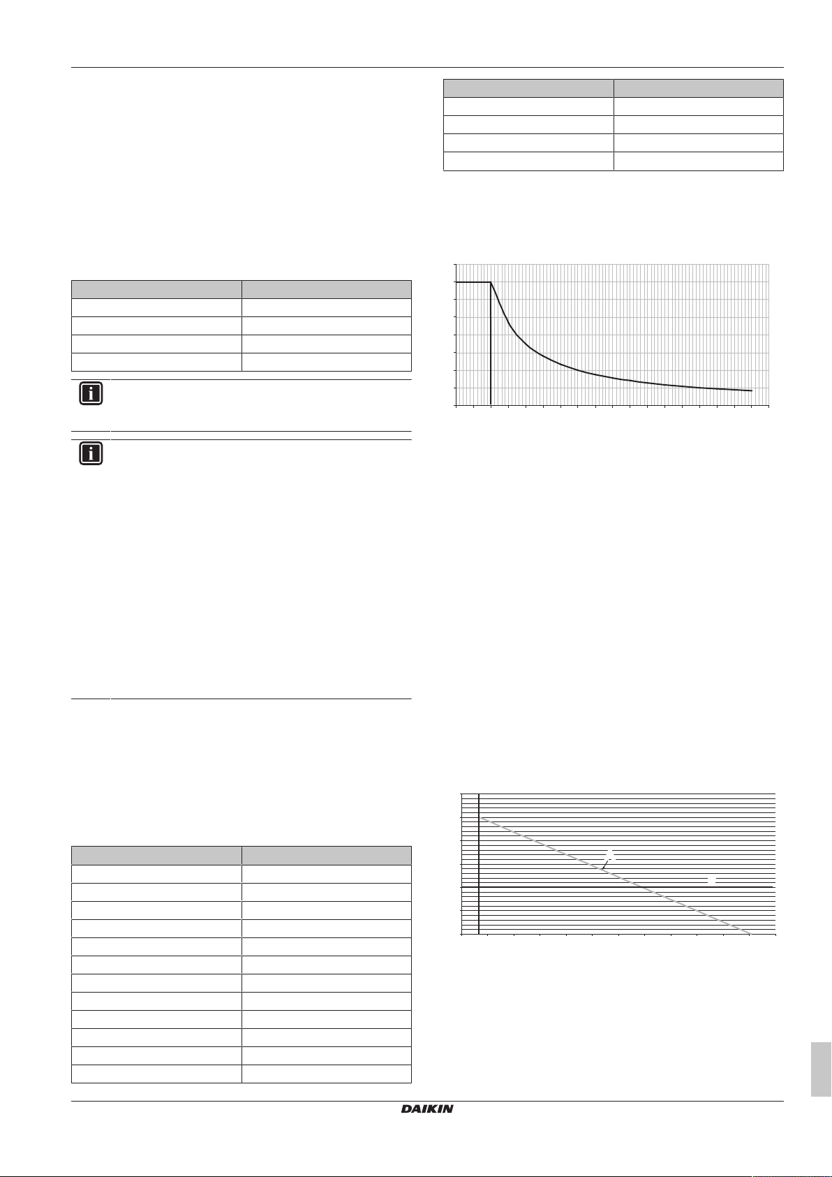
The water volume correction factor according to the curve shown in
the below graph is 3.5; this means that the minimum volume will be
3.5 times larger.
Correction factor curve for minimum water volume
a Water volume correction factor
b Temperature differential (K)
When multiplying 64 l by the correction factor, we get 224 l, which
will be the minimum water volume allowed in the installation if a
temperature differential of 1K is used.
Now it is very important to check that for the height difference of the
system, the volume in the system is less than the maximum allowed
value at that pre-pressure (Pg). If we take a look at the curve, for
1bar of pre-pressure, the maximum volume allowed is 350l.
The total volume in the system will definitely be larger after adding
the internal volume of the unit. In this case, some pre-pressure can
be applied or an additional expansion vessel or buffer tank must be
installed in the field piping.
The default value of pre-pressure (Pg) is for a height difference of
7m.
If the height difference of the system is lower than 7 m AND the
volume in the system is less than the maximum allowed value at that
pre-pressure (Pg) (see graph), then NO pre-pressure (Pg)
adjustment is required.
Maximum water volume
Use the following graph to determine the maximum water volume for
the calculated pre-pressure.
a Pre-pressure (bar)
b Maximum water volume (l)
A System
B Default
If the total water volume in the entire circuit exceeds the maximum
allowed water volume (see graph), an additional expansion vessel
must be installed in the field piping.
Installer and user reference guide
15
5 Preparation
a
5.4.4 Changing the pre-pressure of the expansion vessel
NOTICE
Only a licensed installer may adjust the pre-pressure of the
expansion vessel.
The default pre-pressure of the expansion vessel is 1bar. When it is
required to change the pre-pressure, take following guidelines into
account:
▪ Only use dry nitrogen to set the expansion vessel pre-pressure.
▪ Inappropriate setting of the expansion vessel pre-pressure will
lead to malfunction of the system.
Changing the pre-pressure of the expansion vessel should be done
by releasing or increasing nitrogen pressure through the Schrader
valve of the expansion vessel.
WARNING
▪ If the power supply has a missing or wrong N-phase,
equipment might break down.
▪ Establish proper earthing. Do NOT earth the unit to a
utility pipe, surge absorber, or telephone earth.
Incomplete earthing may cause electrical shock.
▪ Install the required fuses or circuit breakers.
▪ Secure the electrical wiring with cable ties so that the
cables do NOT come in contact with sharp edges or
piping, particularly on the high-pressure side.
▪ Do NOT use taped wires, stranded conductor wires,
extension cords, or connections from a star system.
They can cause overheating, electrical shock or fire.
▪ Do NOT install a phase advancing capacitor, because
this unit is equipped with an inverter. A phase
advancing capacitor will reduce performance and may
cause accidents.
WARNING
▪ All wiring MUST be performed by an authorised
electrician and MUST comply with the applicable
legislation.
▪ Make electrical connections to the fixed wiring.
▪ All components procured on-site and all electrical
construction MUST comply with the applicable
legislation.
a Schrader valve
5.4.5 To check the water volume: Examples
Example 1
The unit is installed 5m below the highest point in the water circuit.
The total water volume in the water circuit is 250l.
No actions or adjustments are required.
Example 2
The unit is installed at the highest point in the water circuit. The total
water volume in the water circuit is 420l.
Actions:
▪ Because the total water volume (420 l) is more than the default
water volume (340l), the pre-pressure must be decreased.
▪ The required pre-pressure is:
Pg = (0.3+(H/10))bar = (0.3+(0/10))bar = 0.3bar
▪ The corresponding maximum water volume is approximately 490l
(see graph).
▪ Because 420 l is lower than 490 l, the expansion vessel is
appropriate for the installation.
5.5 Preparing electrical wiring
5.5.1 About preparing electrical wiring
INFORMATION
Also read the precautions and requirements in the
"General safety precautions" chapter.
WARNING
ALWAYS use multicore cable for power supply cables.
5.5.2 About electrical compliance
This equipment complies with:
▪ EN/IEC 61000‑3‑11 provided that the system impedance Z
less than or equal to Z
at the interface point between the user's
max
supply and the public system.
▪ EN/IEC 61000‑3‑11 = European/International Technical
Standard setting the limits for voltage changes, voltage
fluctuations and flicker in public low-voltage supply systems for
equipment with rated current ≤75A.
▪ It is the responsibility of the installer or user of the equipment to
ensure, by consultation with the distribution network operator if
necessary, that the equipment is connected only to a supply
with a system impedance Z
less than or equal to Z
sys
max
▪ EN/IEC 61000‑3‑12 provided that the short-circuit power Ssc is
greater than or equal to the minimum Ssc value at the interface
point between the user's supply and the public system.
▪ EN/IEC 61000‑3‑12 = European/International Technical
Standard setting the limits for harmonic currents produced by
equipment connected to public low-voltage systems with input
current >16A and ≤75A per phase.
▪ It is the responsibility of the installer or user of the equipment to
ensure, by consultation with the distribution network operator if
necessary, that the equipment is connected only to a supply
with a short-circuit power Ssc greater than or equal to the
minimum Ssc value.
Outdoor unit Z
(Ω) Minimum Ssc value
max
(kVA)
SERHQ020BAW1 0.27 838
SERHQ032BAW1 0.24 873
is
sys
.
Installer and user reference guide
16
Indoor unit Z
(Ω) Minimum Ssc value
max
(kVA)
SEHVX20BAW 0.27 820
SERHQ020~032BAW1 + SEHVX20~64BAW
Split packaged air-cooled water chiller
4P508020-1C – 2019.11
6 Installation
4×
4×
Indoor unit Z
(Ω) Minimum Ssc value
max
(kVA)
SEHVX32BAW 0.24 874
SEHVX40BAW 0.25 1639
SEHVX64BAW 0.22 1747
The local wiring power cord must comply with IEC60245.
The wiring type in protected pipes must be H05VV; H07RN-F must
be used in unprotected pipes.
5.5.3 Cable requirements
Item Cable
bundle
1 PS Indoor unit power supply 4+GND
2 LV Communication cable between indoor
3 LV Standard remote controller (F1/F2) 2
4 LV Secondary remote controller (F1/F2)
5 LV Thermostat ON/OFF signal
6 LV Thermostat cooling/heating signal
7 LV Operation ON signal
8 LV Operation OFF signal
9 HV Cooling/heating output 2 0.3 A
10 HV Operation ON/OFF output 2 0.3 A
11 HV Error output 2 0.3 A
12 HV Water piping heater output 2 1 A
13 HV Pump ON/OFF output 2 0.3 A
unit and outdoor unit
(a) Optional
(b) Refer to the nameplate on the unit or to the technical data
book.
(c) Minimum cable section 0.75mm2.
(d) Minimum cable section 1.5mm2.
PS Power supply
LV Low voltage
HV High voltage
Description Required
(a)
(a)
(a)
(a)
(a)
number of
conductors
(d)
2
2
2
2
2
2
Maximum
running
current
(b)
(d)
(c)
(c)
(c)
(c)
(c)
(c)
5.5.4 Safety device requirements
The power supply must be protected with the required safety
devices, i.e. a main switch, a slow blow fuse on each phase and an
earth leakage protector in accordance with the applicable legislation.
Selection and sizing of the wiring should be done in accordance with
the applicable legislation based on the information mentioned in the
table below.
6 Installation
6.1 Overview: Installation
This chapter describes what you have to do and know on-site to
install the system.
Typical workflow
Installation typically consists of the following stages:
1 Mounting the outdoor unit.
2 Mounting the indoor unit.
3 Connecting the refrigerant piping.
4 Checking the refrigerant piping.
5 Charging refrigerant.
6 Connecting the water piping.
7 Connecting the electrical wiring.
6.2 Opening the units
6.2.1 About opening the units
At certain times, you have to open the unit. Example:
▪ When connecting the electrical wiring
▪ When maintaining or servicing the unit
DANGER: RISK OF ELECTROCUTION
Do NOT leave the unit unattended when the service cover
is removed.
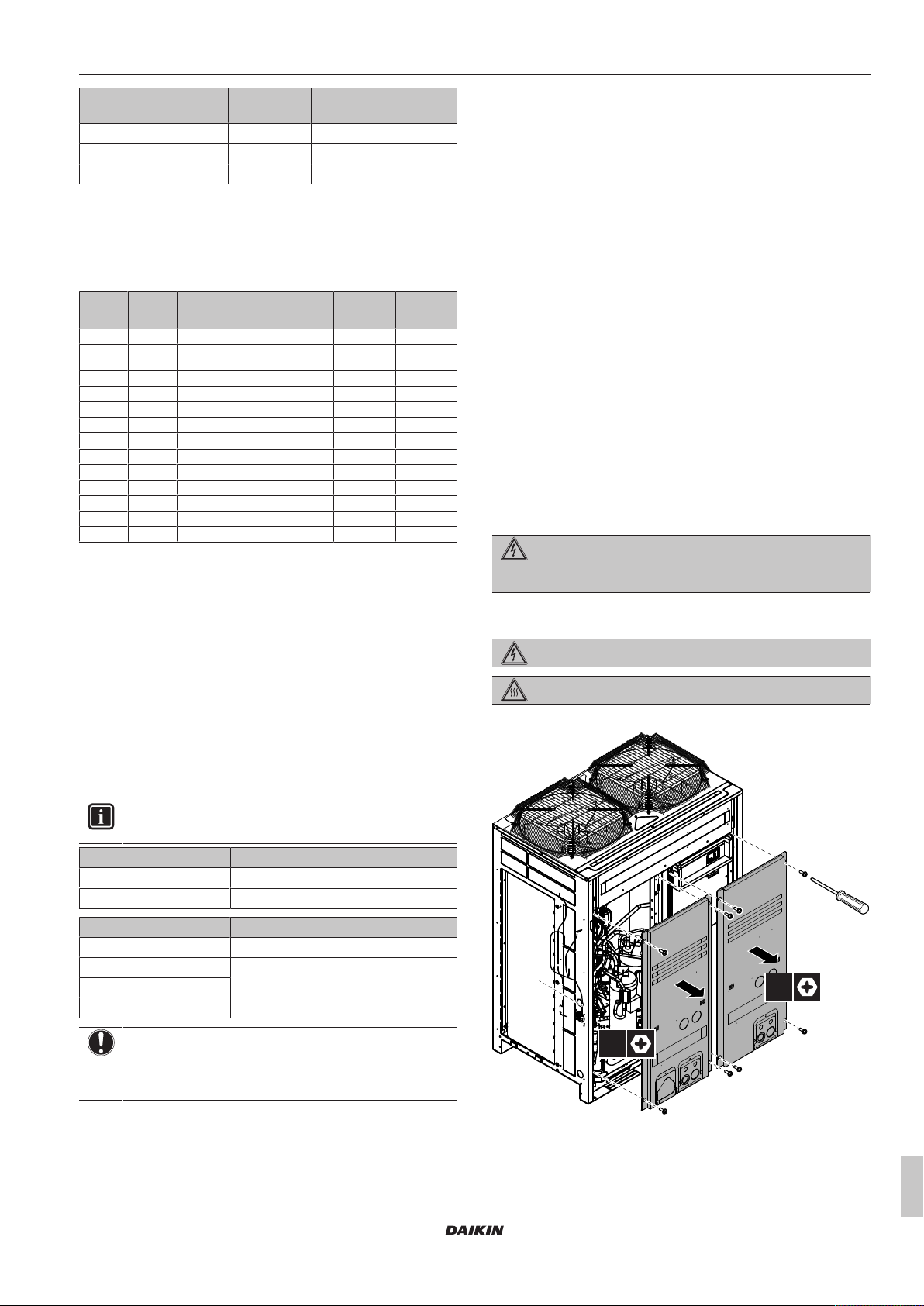
6.2.2 To open the outdoor unit
DANGER: RISK OF ELECTROCUTION
DANGER: RISK OF BURNING
To gain access to the unit, front plates need to be opened as follows:
INFORMATION
Multi units are standard combinations.
Outdoor unit Recommended fuses
SERHQ020BAW1 32A
SERHQ032BAW1 40A
Indoor unit Recommended fuses
SEHVX20BAW 6A
SEHVX32BAW 10A
SEHVX40BAW
SEHVX64BAW
NOTICE
When using residual current operated circuit breakers, be
sure to use a high-speed type 300 mA rated residual
operating current.
SERHQ020~032BAW1 + SEHVX20~64BAW
Split packaged air-cooled water chiller
4P508020-1C – 2019.11
Once the front plates open, the electrical component box can be
accessed. See "6.2.4 To open the electrical component box of the
outdoor unit"[418].
Installer and user reference guide
17
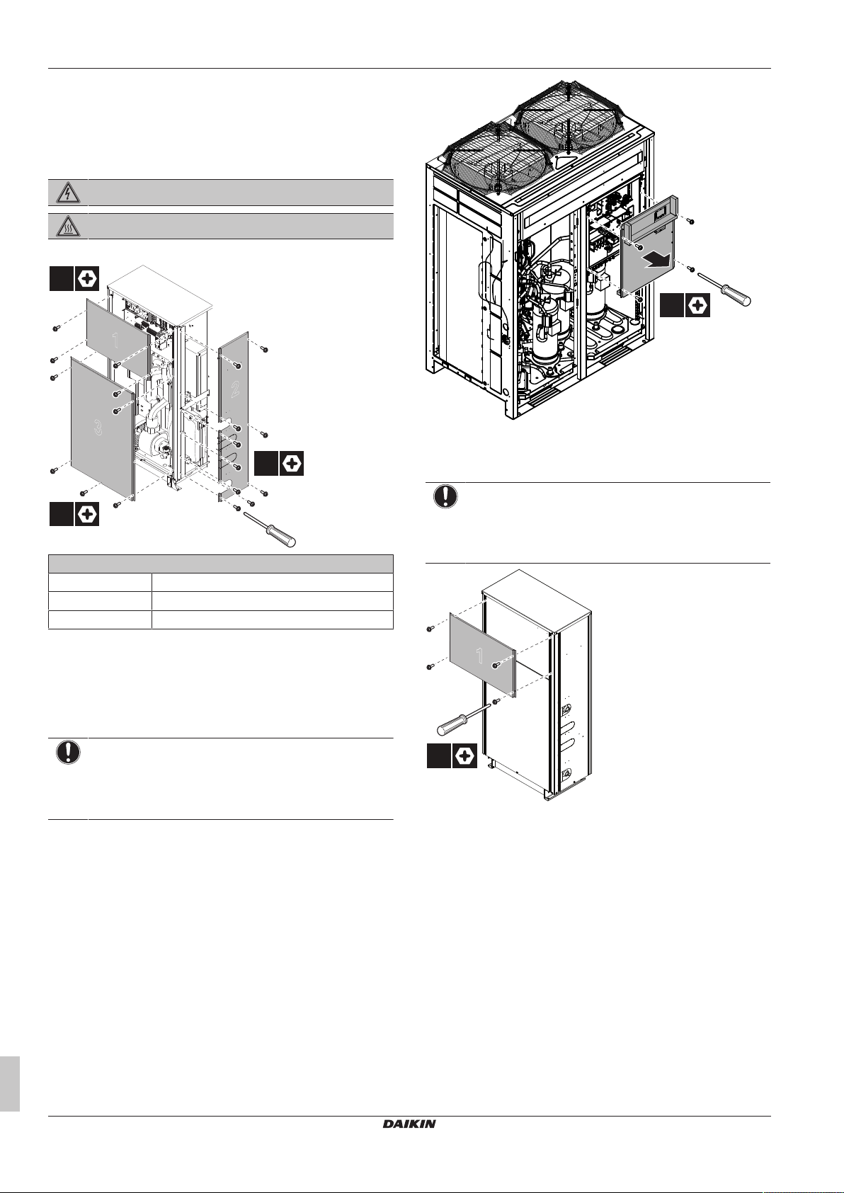
6 Installation
1
3
2
10×
5×
4×
4×
1
4×
For service purposes, the pushbuttons on the main PCB need to be
accessed. To access these pushbuttons, the electrical component
box cover does not need to be opened. See "7.2.3To access the
field setting components"[433].
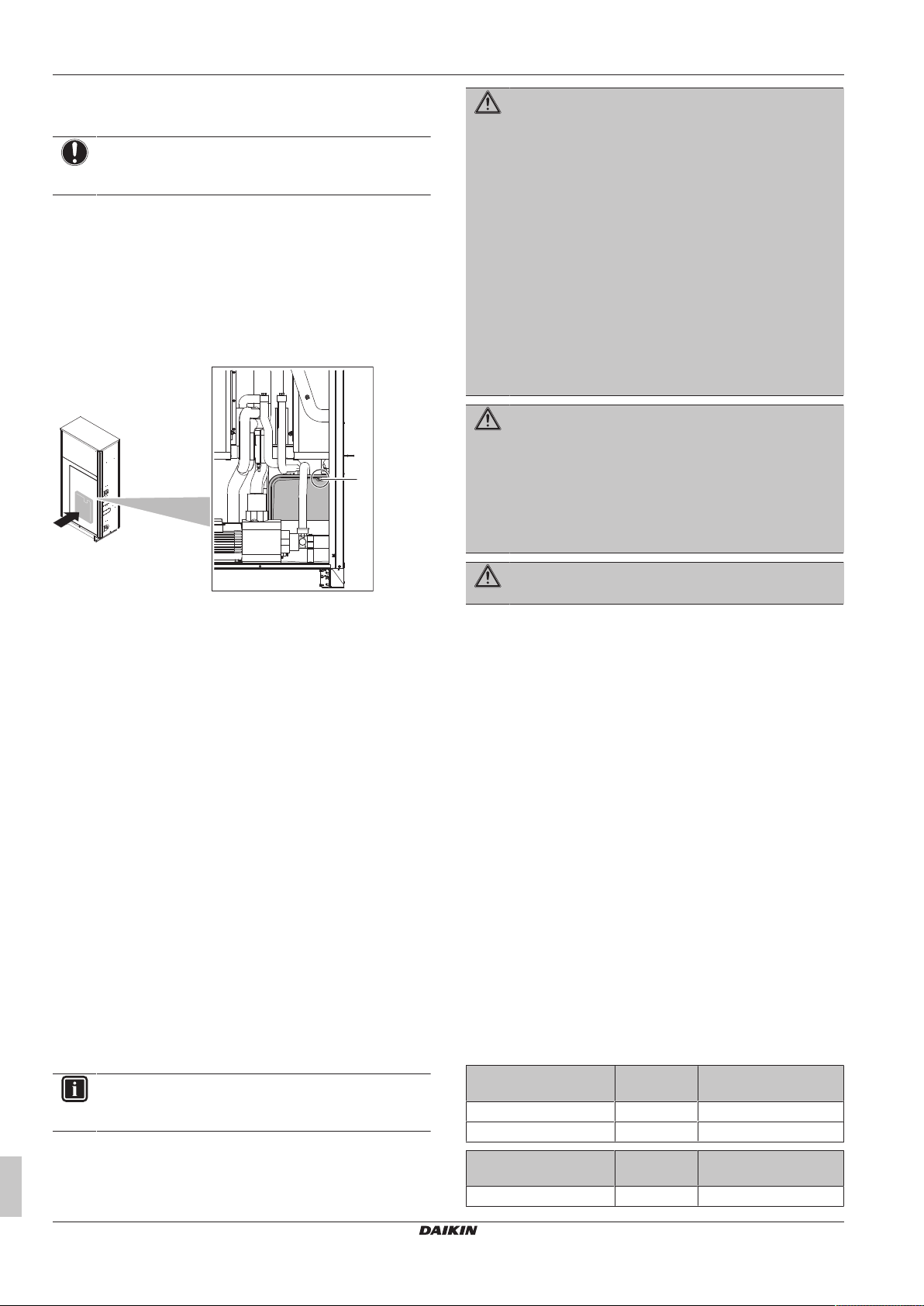
6.2.3 To open the indoor unit
DANGER: RISK OF ELECTROCUTION
DANGER: RISK OF BURNING
To gain access to the unit, front plates need to be opened as follows:
6.2.5 To open the electrical component box of the indoor unit
Panel
1 Electrical parts of the indoor unit
2 Indoor unit (side panel)
3 Indoor unit (front panel)
Once the front plates open, the electrical component box can be
accessed. See "6.2.5 To open the electrical component box of the
indoor unit"[418].
6.2.4 To open the electrical component box of the outdoor unit
NOTICE
Do NOT apply excessive force when opening the
electronic component box cover. Excessive force can
deform the cover, resulting in entering of water to cause
equipment failure.
NOTICE
Do NOT apply excessive force when opening the
electronic component box cover. Excessive force can
deform the cover, resulting in entering of water to cause
equipment failure.
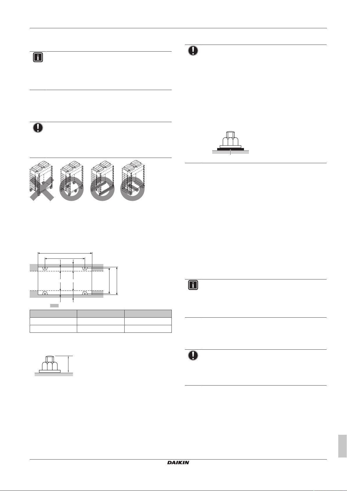
6.3 Mounting the outdoor unit
6.3.1 About mounting the outdoor unit
When
You have to mount the outdoor and indoor unit before you can
connect the refrigerant and water piping.
Typical workflow
Mounting the outdoor unit typically consists of the following stages:
1 Providing the installation structure.
2 Installing the outdoor unit.
3 Providing drainage.
Installer and user reference guide
18
SERHQ020~032BAW1 + SEHVX20~64BAW
Split packaged air-cooled water chiller
4P508020-1C – 2019.11
6 Installation
722-737
≥67≥67
765
6767
A
B
20 mm
a
6.3.2 Precautions when mounting the outdoor unit
INFORMATION
Also read the precautions and requirements in the
following chapters:
▪ General safety precautions
▪ Preparation
6.3.3 To provide the installation structure
Make sure the unit is installed level on a sufficiently strong base to
prevent vibration and noise.
NOTICE
▪ When the installation height of the unit needs to be
increased, do NOT use stands to only support the
corners.
▪ Stands under the unit must be at least 100mm wide.
X Not allowed
O Allowed
▪ The height of the foundation must at least be 150 mm from the
floor. In heavy snowfall areas, this height should be increased,
depending on the installation place and condition.
▪ The preferred installation is on a solid longitudinal foundation
(steel beam frame or concrete).
6.3.4 To provide drainage
NOTICE
▪ Prepare a water drainage channel around the
foundation to drain waste water from around the unit.
▪ If the unit is to be installed on a roof, check the strength
of the roof and its drainage facilities first.
▪ If the unit is to be installed on a frame, install the
waterproofing board within a distance of 150mm under
the unit in order to prevent infiltration of water coming
from under the unit.
▪ When installed in a corrosive environment, use a nut
with plastic washer (a) to protect the nut tightening part
from rust.
6.4 Mounting the indoor unit
6.4.1 About mounting the indoor unit
When
You have to mount the outdoor and indoor unit before you can
connect the refrigerant and water piping.
Typical workflow
Mounting the indoor unit typically consists of the following stages:
1 Providing the installation structure.
2 Installing the indoor unit.
3 Connecting the water piping and the refrigerant piping.
Minimum foundation
Outdoor unit A B
SERHQ020 930 792
SERHQ032 1240 1102
▪ Fasten the unit in place using four foundation bolts M12. It is best
to screw in the foundation bolts until their length remains 20mm
above the foundation surface.
6.4.2 Precautions when mounting the indoor unit
INFORMATION
Also read the precautions and requirements in the
following chapters:
▪ General safety precautions
▪ Preparation
6.4.3 To provide the installation structure
Make sure the unit is installed level on a sufficiently strong base to
prevent vibration and noise.
NOTICE
▪ When the installation height of the unit needs to be
increased, do NOT use stands to only support the
corners.
▪ Stands under the unit must be at least 100mm wide.
▪ The unit must be mounted against the wall.
▪ The unit must be fixed to prevent it from tilting.
▪ The preferred installation is on a solid longitudinal foundation
(steel beam frame or concrete).
▪ Observe the minimum installation space requirements.
SERHQ020~032BAW1 + SEHVX20~64BAW
Split packaged air-cooled water chiller
4P508020-1C – 2019.11
Installer and user reference guide
19
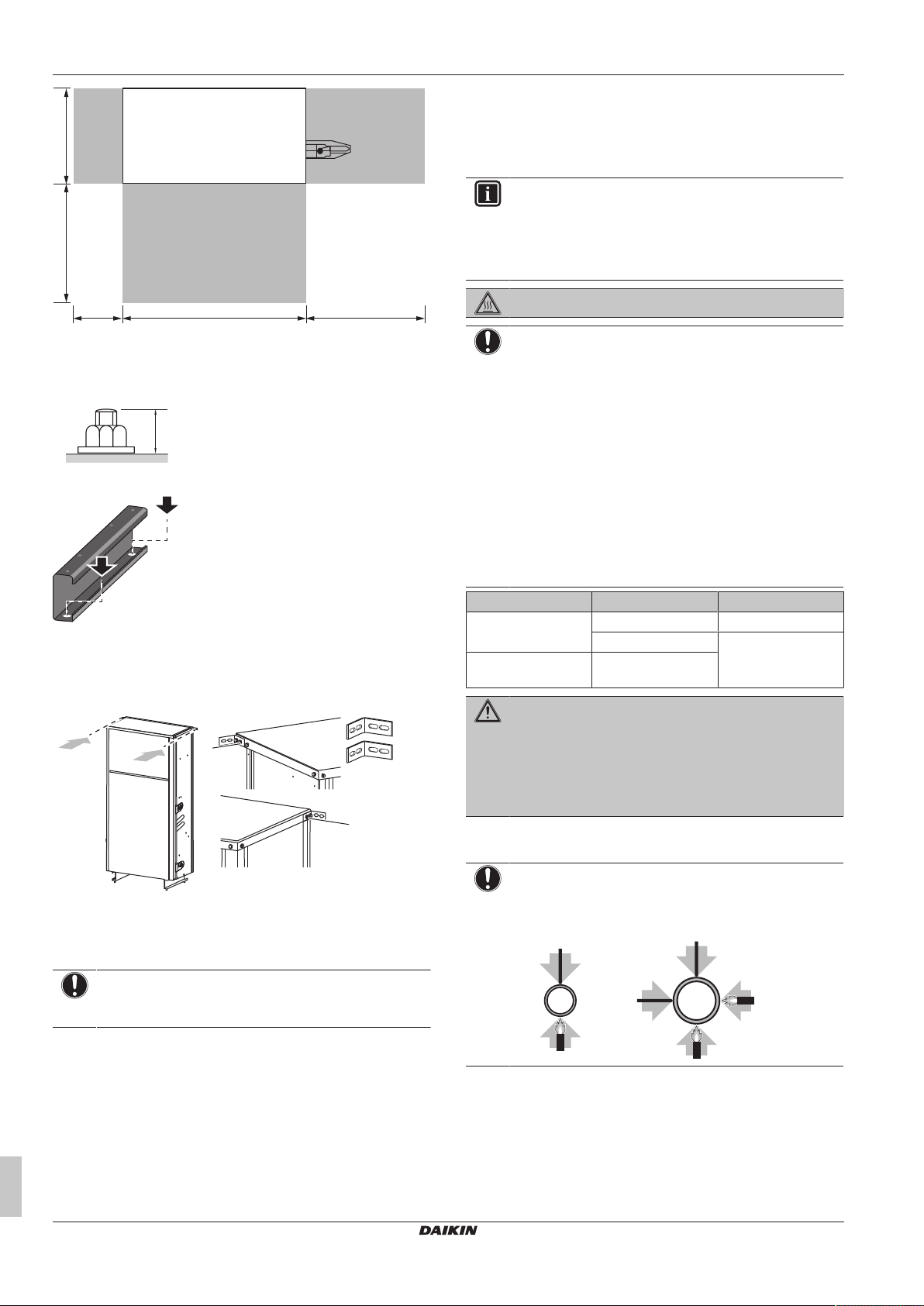
6 Installation
766.5 500200
396500
(mm)
20 mm
b
a
1
1
1
1
2 2
≤Ø25.4 >Ø25.4
▪ Fasten the unit in place using four foundation bolts M12. It is best
to screw in the foundation bolts until their length remains 20mm
above the foundation surface.
▪ Fasten the unit to the floor using the holes in the bottom beams.
▪ Fasten the unit to the wall using the 2 accessory L-shaped
supports to prevent it from falling over. The supports can be fixed
to the top panel of the hydro module (2× M5 screws on either side,
but one screw is already mounted on the right side of the top
plate).
6.5 Connecting the refrigerant piping
6.5.1 Precautions when connecting the refrigerant piping
INFORMATION
Also read the precautions and requirements in the
following chapters:
▪ General safety precautions
▪ Preparation
DANGER: RISK OF BURNING
NOTICE
Take the following precautions on refrigerant piping into
account:
▪ Avoid anything but the designated refrigerant to get
mixed into the refrigerant cycle (e.g. air).
▪ Only use R410A when adding refrigerant.
▪ Only use installation tools (e.g. manifold gauge set) that
are exclusively used for R410A installations to
withstand the pressure and to prevent foreign materials
(e.g. mineral oils and moisture) from mixing into the
system.
▪ Protect the piping as described in the following table to
prevent dirt, liquid or dust from entering the piping.
▪ Use caution when passing copper tubes through walls.
Unit Installation period Protection method
Outdoor unit >1month Pinch the pipe
<1month Pinch or tape the pipe
Indoor unit Regardless of the
period
WARNING
Connect the refrigerant piping securely before running the
compressor. If the refrigerant piping is NOT connected and
the stop valve is open when the compressor is run, air will
be sucked in. This will cause abnormal pressure in the
refrigeration cycle, which may result in equipment damage
and even injury.
a Attach one L-shaped support to the left side of the top plate
using 2screws from the accessory bag
b Attach the other L-shaped support to the right side of the
top plate using 1screw from the accessory bag and
1screw that is already attached to the unit
NOTICE
Use the proper kind of screw for the type of wall or
foundation material where the unit will be fixed to.
Installer and user reference guide
20
6.5.2 To braze the pipe end
NOTICE
Precautions when connecting field piping. Add brazing
material as shown in the figure.
▪ When brazing, blow through with nitrogen to prevent creation of
large quantities of oxidised film on the inside of the piping. This
film adversely affects valves and compressors in the refrigerating
system and prevents proper operation.
▪ Set the nitrogen pressure to 20 kPa (0.2 bar) (just enough so it
can be felt on the skin) with a pressure-reducing valve.
SERHQ020~032BAW1 + SEHVX20~64BAW
Split packaged air-cooled water chiller
4P508020-1C – 2019.11
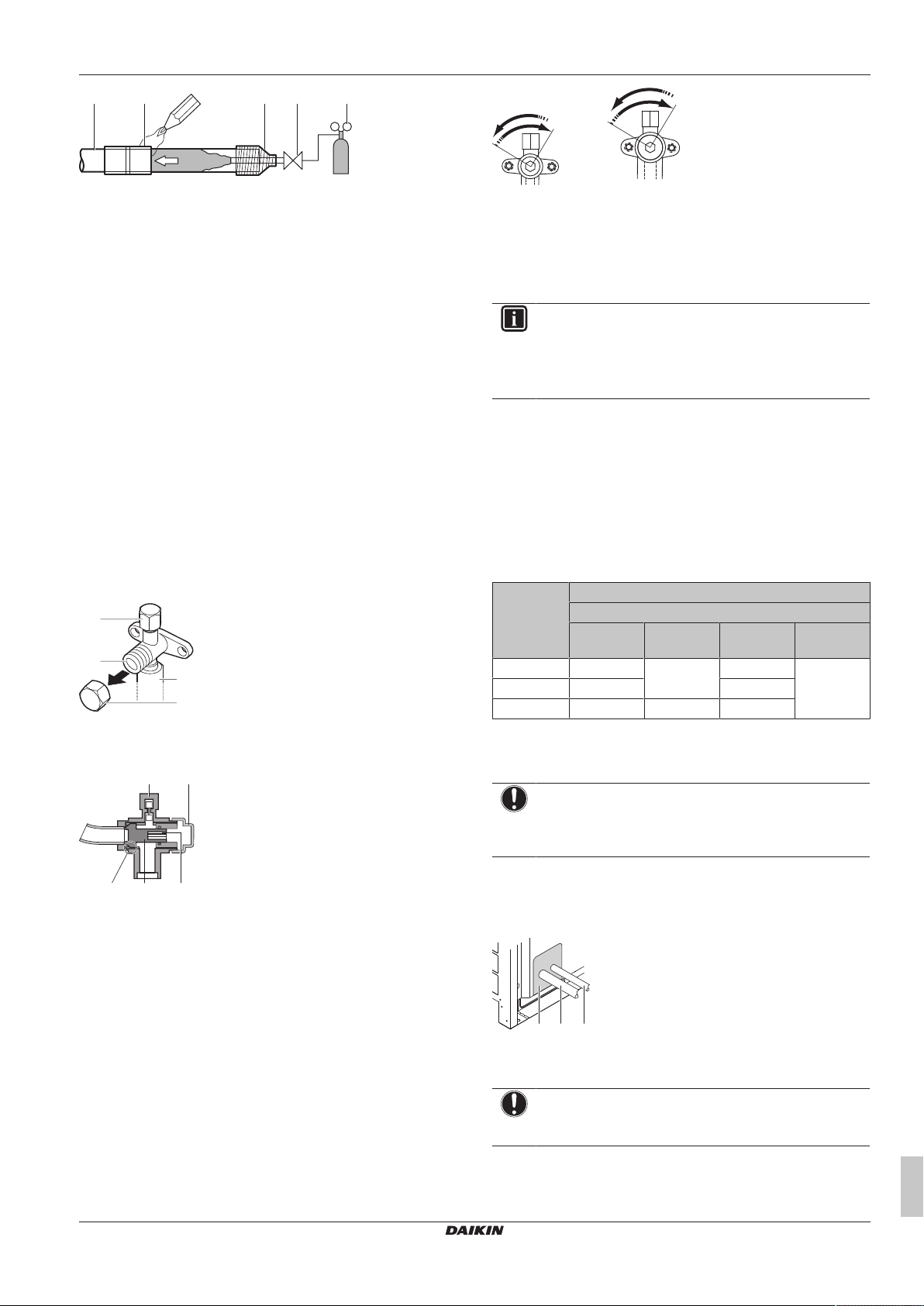
6 Installation
a b c d e
f
f
c
d
a
b
a b
cde
a b c
a Refrigerant piping
b Part to be brazed
c Taping
d Manual valve
e Pressure-reducing valve
f Nitrogen
▪ Do NOT use anti-oxidants when brazing pipe joints.
Residue can clog pipes and break equipment.
▪ Do NOT use flux when brazing copper-to-copper refrigerant
piping. Use phosphor copper brazing filler alloy (BCuP), which
does not require flux.
Flux has an extremely harmful influence on refrigerant piping
systems. For instance, if chlorine based flux is used, it will cause
pipe corrosion or, in particular, if the flux contains fluorine, it will
deteriorate the refrigerant oil.
▪ Always protect the surrounding surfaces (e.g. insulation foam)
from heat when brazing.
6.5.3 Using the stop valve and service port
To handle the stop valve
Take the following guidelines into account:
▪ The stop valves are factory closed.
▪ The following illustrations show each part required in handling the
valve.
a Service port and service port cover
b Stop valve
c Field piping connection
d Stop valve cover
Counterclockwise to open.
Clockwise to close.
3 When the stop valve CANNOT be turned any further, stop
turning.
4 Install the stop valve cover.
Result: The valve is now open/closed.
INFORMATION
▪ The SERHQ020 supports Ø22.2 field piping on the
accessory pipe supplied with the unit.
▪ The SERHQ032 supports Ø28.6 field piping on the
accessory pipe supplied with the unit.
To handle the service port
▪ Always use a charge hose equipped with a valve depressor pin,
since the service port is a Schrader type valve.
▪ After handling the service port, make sure to tighten the service
port cover securely. For the tightening torque, refer to the table
below.
▪ Check for refrigerant leaks after tightening the service port cover.
Tightening torques
Stop valve
size (mm)
Ø9.5 5.4~6.6 4mm 13.5~16.5 11.5~13.9
Ø12.7 8.1~9.9 18.0~22.0
Ø25.4 27.0~33.0 8mm 22.5~27.5
Tightening torque N•m (turn clockwise to close)
Shaft
Valve body Hexagonal
wrench
Cap (valve
lid)
Service
port
6.5.4 To connect the refrigerant piping to the outdoor unit
a Service port
b Stop valve cover
c Hexagon hole
d Shaft
e Seal
▪ Keep both stop valves open during operation.
▪ Do NOT apply excessive force to the stop valve. Doing so may
break the valve body.
To open/close the stop valve
1 Remove the stop valve cover.
2 Insert a hexagon wrench (liquid side: 4 mm, gas side: 8mm)
into the stop valve and turn the stop valve:
SERHQ020~032BAW1 + SEHVX20~64BAW
Split packaged air-cooled water chiller
4P508020-1C – 2019.11
NOTICE
All field piping must be installed by a licensed refrigeration
technician and must comply with the relevant local and
national regulations.
Seal the piping and wiring intake holes using sealing material (field
supply), otherwise the capacity of the unit will drop and small
animals may enter the machine.
Example: passing piping out through the front
a Plug the grey areas (piping routed through the front panel)
b Gas side piping
c Liquid side piping
NOTICE
After all the piping has been connected, make sure there is
no gas leak. Use nitrogen to perform a gas leak detection.
Installer and user reference guide
21
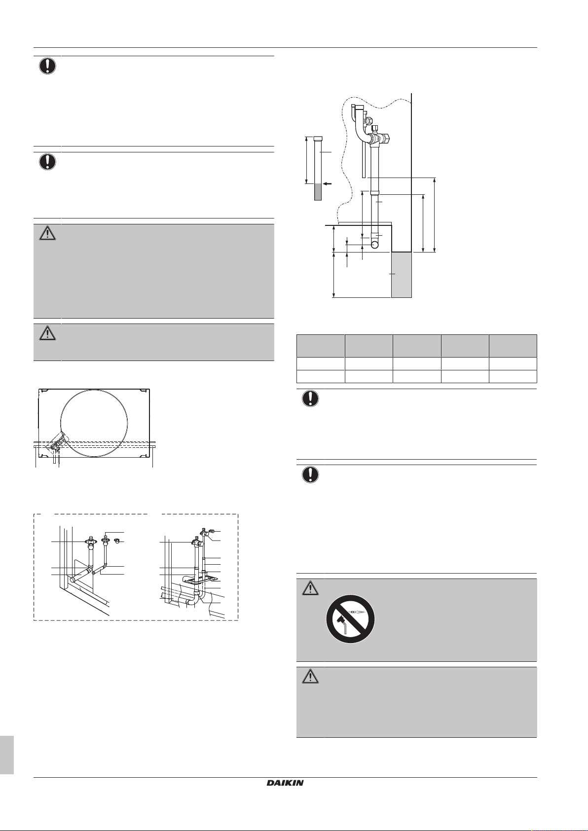
6 Installation
a b c
c
b
h
f
d
h
a
c
b
g
h
ih
j
k
h
h
h
e
i
a
A B
A
AB
C
D
a
b
a
c
d
25
150 90
NOTICE
▪ Be sure to use the supplied accessory pipes when
carrying out piping work in the field.
▪ Be sure that the field installed piping does not touch
other pipes, the bottom panel or side panel. Especially
for the bottom and side connection, be sure to protect
the piping with suitable insulation, to prevent it from
coming into contact with the casing.
NOTICE
Use a 2-stage vacuum pump with a non-return valve that
can evacuate to a gauge pressure of −100.7 kPa
(−1.007 bar)(5 Torr absolute). Make sure the pump oil
does not flow oppositely into the system while the pump is
not working.
WARNING
Take sufficient precautions in case of refrigerant leakage. If
refrigerant gas leaks, ventilate the area immediately.
Possible risks:
▪ Excessive refrigerant concentrations in a closed room
can lead to oxygen deficiency.
▪ Toxic gas may be produced if refrigerant gas comes
into contact with fire.
WARNING
NEVER directly touch any accidental leaking refrigerant.
This could result in severe wounds caused by frostbite.
The refrigerant piping can be installed from the front or from the side
of the unit (when taken out from the bottom) as shown in the figure.
Cutting the gas side accessory pipe
When connecting the refrigerant piping from the side, cut the gas
side accessory pipe as shown in the figure.
a Gas side accessory pipe
b Cut here
c Gas side piping (field supply)
d Unit base
Outdoor
A B C D
unit
SERHQ020 156 23 192 247
SERHQ032 150 29 192 251
NOTICE
▪ When connecting the piping on site, be sure to use the
accessory piping.
▪ Make sure the onsite piping does not come into contact
with other piping, the bottom frame or side panels of
the unit.
a Left-side connection
b Front connection
c Right-side connection
A For front connection, remove the stop valve cover to
connect the refrigerant piping.
B For side connection, remove the knockouts in the bottom
frame and route the piping under the bottom frame.
a Gas pipe stop valve
b Liquid pipe stop valve
Installer and user reference guide
22
c Service port for adding refrigerant
d Gas side accessory pipe (1)
e Gas side accessory pipe (2)
f Liquid side accessory pipe (1)
g Liquid side accessory pipe (2)
h Brazing
i Gas side piping (field supply)
j Liquid side piping (field supply)
k Open the knockout holes with a hammer
NOTICE
Precautions when making knockout holes:
▪ Avoid damaging the casing.
▪ After making the knockout holes, we recommend you
remove the burrs and paint the edges and areas
around the edges using repair paint to prevent rusting.
▪ When passing electrical wiring through the knockout
holes, wrap the wiring with protective tape to prevent
damage.
WARNING
Never remove the pinched piping by brazing.
WARNING
Any gas or oil remaining inside the stop valve may blow off
the pinched piping.
Failure to observe the instructions in procedure below
properly may result in property damage or personal injury,
which may be serious depending on the circumstances.
Use the following procedure to remove the pinched piping:
SERHQ020~032BAW1 + SEHVX20~64BAW
Split packaged air-cooled water chiller
4P508020-1C – 2019.11

6 Installation
a
b
c
b
c
B
A
a
b
VRV
C1
VRV
C2
f
e
g
C2
g
C1
C1
C2
d
d
a
b
c
1 Remove the valve lid and make sure that the stop valves are
fully closed.
2 Connect a charge hose to service ports of all stop valves.
3 Recover gas and oil from the pinched piping by using a
recovery unit.
CAUTION
Do not vent gases into the atmosphere.
4 When all gas and oil is recovered from the pinched piping,
disconnect the charge hose and close the service ports.
5 If the pinched piping lower part looks like detail A in the figure
below, perform the last 2steps of this procedure.
6 If the pinched piping lower part looks like detail B in the figure
below, perform the last 3steps of this procedure.
7 Cut off the lower part of the smaller pinched piping with an
appropriate tool (e.g. a pipe cutter, a pair of nippers, …) so that
a cross-section is open, allowing remaining oil to drip out in
case the recovery was not complete. Wait until all oil has
dripped out.
a Knockout hole
b Grommet
▪ First cut off the refrigerant liquid piping inside the unit
approximately 7 cm before the clamp and the refrigerant gas
piping 4 cm before the clamp. This is necessary in order to avoid
the piping cutter tool from interfering with the piping. Remove any
burrs from the piping.
▪ Use accessory pipes to connect field refrigerant piping to the
piping connections on the indoor unit. For SEHVX20BAW, after
cutting off the end of both the liquid and gas refrigerant piping,
braze accessory pipe 1 to the liquid connection and accessory
pipe 2 to the gas connection. For SEHVX32BAW, after cutting off
the end of both the liquid and gas refrigerant piping, braze the field
piping directly to the liquid connection and accessory pipe 2 to the
gas connection. For SEHVX40BAW, perform the procedure for
SEHVX20BAW twice. For SEHVX64BAW, perform the procedure
for SEHVX32BAW twice.
NOTICE
After brazing, fix the pipes to the unit using the clamps in
the pipe supports.
8 Cut the pinched piping off with a pipe cutter just above the
brazing point or just above the marking if there is no brazing
point.
9 Wait until all oil is dripped out in case the recovery was not
complete, and only then proceed with connection of the field
piping.
a Service port
b Stop valve
c Point of pipe cutting just above brazing point or above
marking
A+B Pinched piping
6.5.5 To connect the refrigerant piping to the indoor unit
▪ For the SEHVX20+32BAW, remove the top knockout hole in the
side service plate and add the grommet (accessory) to cover any
burrs. For the SEHVX40+64BAW, remove both top and bottom
knockout holes in the side service plate and add the grommets
(accessory) to cover any burrs.
a Indoor unit
b Outdoor unit 1
c Outdoor unit 2 (only in case of SEHVX40+64BAW)
d Refrigerant piping
e Pump
f Switchbox
g Evaporator
NOTICE
When installing the piping between the outdoor and indoor
units, also refer to the figure in "6.9.7To connect the power
supply and transmission cables"[431].
6.6 Checking the refrigerant piping
SERHQ020~032BAW1 + SEHVX20~64BAW
Split packaged air-cooled water chiller
4P508020-1C – 2019.11
6.6.1 About checking the refrigerant piping
The outdoor unit's internal refrigerant piping has been factory tested
for leaks. You only have to check the outdoor unit's external
refrigerant piping.
Installer and user reference guide
23

6 Installation
f
i
h
a
b
d
c
e
k
l
m
j
g
f
f
e
a
d
c
b
d
e
Before checking the refrigerant piping
Make sure the refrigerant piping is connected between the outdoor
unit and the indoor unit.
Typical workflow
Checking the refrigerant piping typically consists of the following
stages:
1 Checking for leaks in the refrigerant piping.
2 Performing vacuum drying to remove all moisture, air or
nitrogen from the refrigerant piping.
If there is a possibility of moisture being present in the refrigerant
piping (for example, water may have entered the piping), first carry
out the vacuum drying procedure below until all moisture has been
removed.
6.6.2 Precautions when checking the refrigerant piping
INFORMATION
Also read the precautions and requirements in the
following chapters:
▪ General safety precautions
▪ Preparation
NOTICE
Use a 2-stage vacuum pump with a non-return valve that
can evacuate to a gauge pressure of −100.7 kPa
(−1.007 bar)(5 Torr absolute). Make sure the pump oil
does not flow oppositely into the system while the pump is
not working.
NOTICE
Use this vacuum pump for R410A exclusively. Using the
same pump for other refrigerants may damage the pump
and the unit.
6.6.3 Checking refrigerant piping: Setup
6.6.4 To check for leaks: Pressure leak test
NOTICE
After all the piping has been connected, make sure there is
no gas leak. Use nitrogen to perform a gas leak detection.
1 Break the vacuum by pressurising with nitrogen gas to a gauge
pressure of 4.0 MPa (40 bar). Never set the gauge pressure
higher than the maximum operation pressure of the unit, i.e.
4.0MPa (40bar).
6.6.5 To perform vacuum drying
To remove all moisture from the system, proceed as follows:
1 Evacuate the system for at least 2 hours to a target vacuum of
–100.7kPa (–1.007bar)(5Torr absolute).
2 Check that, with the vacuum pump turned off, the target
vacuum is maintained for at least 1 hour.
3 Should you fail to reach the target vacuum within 2 hours or
maintain the vacuum for 1 hour, the system may contain too
much moisture. In that case, break the vacuum by pressurising
with nitrogen gas to a gauge pressure of 0.05 MPa (0.5 bar)
and repeat steps 1 to 3 until all moisture has been removed.
NOTICE
In case of SEHVX40+64BAW, perform the operations on
both units.
6.6.6 To insulate the refrigerant piping
After finishing the leak test and vacuum drying, the piping must be
insulated. Take into account the following points:
▪ Be sure to insulate the liquid and gas piping (for all units).
▪ Use heat resistant polyethylene foam which can withstand a
temperature of 70°C for liquid piping and polyethylene foam which
can withstand a temperature of 120°C for gas piping.
▪ Reinforce the insulation on the refrigerant piping according to the
installation environment.
Ambient
temperature
≤30°C 75% to 80% RH 15mm
>30°C ≥80% RH 20mm
Humidity Minimum thickness
▪ If there is a possibility that condensation on the stop valve might
drip down into the indoor unit through gaps in the insulation and
piping because the outdoor unit is located higher than the indoor
unit, this must be prevented by sealing up the connections. See
a Pressure reducing valve
b Nitrogen
c Weighing scales
d R410A refrigerant tank (siphon system)
e Vacuum pump
f Charge hose
g Service port for adding refrigerant
h Liquid line stop valve
i Gas line stop valve
j Stop valve service port
k Valve A
l Valve B
m Valve C
Valve State of valve
Valve A Close
Valve B Open
Valve C Close
Liquid line stop valve Close
Gas line stop valve Close
Installer and user reference guide
24
below figure.
a Gas line stop valve
b Liquid line stop valve
c Service port for adding refrigerant
d Sealing up treatment
e Insulation
f Piping between indoor and outdoor unit
DANGER: RISK OF BURNING
Be sure to insulate local pipes, as touching them can
cause burns.
SERHQ020~032BAW1 + SEHVX20~64BAW
Split packaged air-cooled water chiller
4P508020-1C – 2019.11

6 Installation
m
n
c
e
d
b
a
g
h
i
f
j
k
l
6.7 Charging refrigerant
6.7.1 About charging refrigerant
Once vacuum drying is finished, additional refrigerant charging can
start.
6.7.2 Precautions when charging refrigerant
INFORMATION
Also read the precautions and requirements in the
following chapters:
▪ General safety precautions
▪ Preparation
WARNING
▪ Only use R410A as refrigerant. Other substances may
cause explosions and accidents.
▪ R410A contains fluorinated greenhouse gases. Its
global warming potential (GWP) value is 2087.5. Do
NOT vent these gases into the atmosphere.
▪ When charging refrigerant, always use protective
gloves and safety glasses.
NOTICE
If the power of some units is turned off, the charging
procedure cannot be finished properly.
NOTICE
Be sure to turn on the power 6 hours before operation in
order to have power running to the crankcase heater and
to protect the compressor.
NOTICE
If operation is performed within 12 minutes after the indoor
and outdoor units are turned on, the H2P LED will be lit
and the compressor will not operate before communication
is established between outdoor unit(s) and indoor units.
6.7.3 To determine the additional refrigerant amount
INFORMATION
For final charge adjustment in a test laboratory, contact
your dealer.
Refrigerant type: R410A
Global warming potential (GWP) value: 2087.5
The additional refrigerant charge calculation is based on the liquid
piping size.
Formula:
R=(X
×0.059)+(X
Ø9.52
R Additional refrigerant to be charged [in kg and rounded off
X
1, 2
×0.12)
Ø12.7
to 1 decimal place]
Total length [m] of liquid piping size at Øa
Example
SEHVX64BAW (indoor unit) + 2× SERHQ032BAW1 (outdoor unit)
R=(L1+L2)
×0.12
Ø12.7
L1 Liquid pipe of circuit 1 (indoor → outdoor1)
L2 Liquid pipe of circuit 2 (indoor → outdoor2)
6.7.4 To charge refrigerant
Pre-charging refrigerant
1 Calculate the additional amount of refrigerant to be added using
the formula mentioned in "6.7.3 To determine the additional
refrigerant amount"[425].
2 Open valve C (valves A and B and the stop valves must be left
closed) and charge the refrigerant in liquid form via the liquid
side stop valve service port.
3 Close valve C when the calculated amount for pre-charging is
reached.
NOTICE
Close the front panel before any refrigerant charge
operation is executed. Without the front panel attached the
unit cannot judge correctly whether it is operating properly
or not.
NOTICE
In case of maintenance and the system (outdoor unit+field
piping+indoor units) does not contain any refrigerant any
more (e.g., after refrigerant reclaim operation), the unit has
to be charged with its original amount of refrigerant (refer
to the nameplate on the unit) by pre-charging before the
automatic charging function can be started.
NOTICE
▪ The refrigerant charging port is connected to the piping
inside the unit. The unit's internal piping is already
factory charged with refrigerant, so be careful when
connecting the charge hose.
▪ After adding the refrigerant, do not forget to close the
lid of the refrigerant charging port. The tightening
torque for the lid is 11.5 to 13.9N•m.
a Weighing scales
b Refrigerant R410A tank (siphon system)
c Charge hose
d Liquid line stop valve
e Gas line stop valve
f Stop valve service port
g Valve B
h Valve C
i Valve A
j Refrigerant charge port
k Interunit piping
l Refrigerant piping
m Field piping
n Gas flow
NOTICE
In case of maintenance and the system (outdoor unit+field
piping+indoor units) does not contain any refrigerant any
more (e.g., after refrigerant reclaim operation), the unit has
to be charged with its original amount of refrigerant (refer
to the nameplate on the unit).
▪ In order to ensure uniform refrigerant distribution, it
may take the compressor ±10 minutes to start up after
the unit has started operation. This is not a malfunction.
6.7.5 Checks after charging refrigerant
▪ Are all stop valves open?
SERHQ020~032BAW1 + SEHVX20~64BAW
Split packaged air-cooled water chiller
4P508020-1C – 2019.11
Installer and user reference guide
25

6 Installation
b
Contains fluorinated greenhouse gases
2
1
1
1
2
2
kg
tCO2eq
GWP × kg
1000
=
=
+
kg
=
kg
=
GWP: XXX
RXXX
a
f
c
d
e
▪ Is the amount of refrigerant, that has been added, recorded on the
refrigerant charge label?
NOTICE
Make sure to open all stop valves after (pre-) charging the
refrigerant.
Operating with the stop valves closed will damage the
compressor.
6.8.3 To connect the water piping
Water connections must be made in accordance with all applicable
legislations and the outlook drawing delivered with the unit,
respecting the water inlet and outlet.
NOTICE
Do NOT use excessive force when connecting the piping.
Deformation of the piping can cause malfunctioning of the
unit.
6.7.6 To fix the fluorinated greenhouse gases label
1 Fill in the label as follows:
If dirt gets in the water circuit, problems may occur. Therefore,
always take into account the following when connecting the water
circuit:
▪ Use clean pipes only.
▪ Hold the pipe end downwards when removing burrs.
▪ Cover the pipe end when inserting it through a wall so that no dust
and dirt enter.
▪ Use a good thread sealant for the sealing of the connections. The
sealing must be able to withstand the pressures and temperatures
a If a multilingual fluorinated greenhouse gases label is
delivered with the unit (see accessories), peel off the
applicable language and stick it on top of a.
b Factory refrigerant charge: see unit name plate
c Additional refrigerant amount charged
d Total refrigerant charge
e Quantity of fluorinated greenhouse gases of the total
refrigerant charge expressed as tonnes CO2 equivalent.
f GWP = Global warming potential
of the system.
▪ When using non-brass metallic piping, make sure to insulate both
materials from each other to prevent galvanic corrosion.
▪ Make sure to provide a proper drain for the pressure relief valve.
▪ Because brass is a soft material, use appropriate tooling for
connecting the water circuit. Inappropriate tooling will cause
damage to the pipes.
NOTICE
Applicable legislation on fluorinated greenhouse gases
requires that the refrigerant charge of the unit is indicated
both in weight and CO2 equivalent.
Formula to calculate the quantity in CO2 equivalent
tonnes: GWP value of the refrigerant × total refrigerant
charge [in kg] / 1000
Use the GWP value mentioned on the refrigerant charge
label. That GWP is based on the current legislation on
fluorinated greenhouse gases. The GWP mentioned in the
manual might be outdated.
2 Fix the label on the inside of the unit near the charging port
(e.g. on the inside of the service cover).
▪ For correct operation of the system, a regulating valve must be
installed in the water system. The regulating valve is to be used to
regulate the water flow in the system (field supply).
6.8.4 To fill the water circuit
1 Connect the water supply to the drain and fill valve.
2 Make sure the automatic air purge valve is open (at least 2
turns).
6.8 Connecting water piping
3 Fill with water until the pressure gauge indicates a pressure of
approximately 2.0 bar. Remove air in the circuit as much as
6.8.1 About connecting the water piping
Before connecting the water piping
Typical workflow
Connecting the water piping typically consists of the following
stages:
1 Connecting the water piping of the indoor unit.
2 Filling the water circuit.
3 Insulating the water piping.
6.8.2 Precautions when connecting the water piping
INFORMATION
Also read the precautions and requirements in the
following chapters:
▪ General safety precautions
possible using the air purge valves (refer to field setting [E‑04]
in "7.2.9Field settings on the user interface"[435]).
NOTICE
▪ Air in the water circuit can cause malfunctioning. During
filling, it may not be possible to remove all the air from
the circuit. Remaining air will be removed through the
automatic air purge valves during the initial operating
hours of the system. Additional filling with water
afterwards may be required.
▪ To purge the system, use the special function as
described in "8Commissioning"[440].
NOTICE
The water pressure indicated on the manometer will vary
depending on the water temperature (higher pressure at
higher water temperature).
However, at all times water pressure shall remain above
1bar to avoid air entering the circuit.
▪ Preparation
Installer and user reference guide
26
SERHQ020~032BAW1 + SEHVX20~64BAW
Split packaged air-cooled water chiller
4P508020-1C – 2019.11

6 Installation
NOTICE
Make sure water quality complies with EU directive
98/83EC.
INFORMATION
The unit may dispose of some excessive water through the
pressure relief valve.
6.8.5 To insulate the water piping
The piping in the complete water circuit MUST be insulated to
prevent condensation during cooling operation and reduction of the
heating and cooling capacity.
To prevent the freezing of the outdoor water piping during winter
time, the thickness of the sealing material MUST be at least 13 mm
(with λ=0.039W/mK).
If the temperature is higher than 30°C and the humidity is higher
than RH 80%, the thickness of the insulation materials should be at
least 20 mm to prevent condensation on the surface of the
insulation.
6.9 Connecting the electrical wiring
6.9.1 About connecting the electrical wiring
Before connecting the electrical wiring
Make sure:
▪ The refrigerant piping is connected and checked
▪ The water piping is connected
Typical workflow
Connecting the electrical wiring typically consists of the following
stages:
1 Making sure the power supply system complies with the
electrical specifications of the units.
2 Connecting the electrical wiring to the outdoor unit.
3 Connecting the electrical wiring to the indoor unit.
4 Connecting the main power supply.
6.9.2 Precautions when connecting the electrical wiring
DANGER: RISK OF ELECTROCUTION
WARNING
All field wiring and components MUST be installed by a
licensed electrician and MUST comply with the applicable
legislation.
WARNING
If NOT factory installed, a main switch or other means for
disconnection, having a contact separation in all poles
providing full disconnection under overvoltage category III
condition, MUST be installed in the fixed wiring.
WARNING
▪ ONLY use copper wires.
▪ Make sure the field wiring complies with the applicable
legislation.
▪ All field wiring MUST be performed in accordance with
the wiring diagram supplied with the product.
▪ NEVER squeeze bundled cables and make sure they
do NOT come in contact with the piping and sharp
edges. Make sure no external pressure is applied to the
terminal connections.
▪ Make sure to install earth wiring. Do NOT earth the unit
to a utility pipe, surge absorber, or telephone earth.
Incomplete earth may cause electrical shock.
▪ Make sure to use a dedicated power circuit. NEVER
use a power supply shared by another appliance.
▪ Make sure to install the required fuses or circuit
breakers.
▪ Make sure to install an earth leakage protector. Failure
to do so may cause electric shock or fire.
▪ When installing the earth leakage protector, make sure
it is compatible with the inverter (resistant to high
frequency electric noise) to avoid unnecessary opening
of the earth leakage protector.
Install power cables at least 1 m away from televisions or radios to
prevent interference. Depending on the radio waves, a distance of
1m may not be sufficient.
WARNING
▪ After finishing the electrical work, confirm that each
electrical component and terminal inside the electrical
components box is connected securely.
▪ Make sure all covers are closed before starting up the
unit.
NOTICE
Do NOT operate the unit until the refrigerant piping is
complete. Running the unit before the piping is ready will
break the compressor.
NOTICE
If the power supply has a missing or wrong N-phase,
equipment will break down.
NOTICE
Do NOT install a phase advancing capacitor, because this
unit is equipped with an inverter. A phase advancing
capacitor will reduce performance and may cause
accidents.
NOTICE
NEVER remove a thermistor, sensor, etc., when
connecting power wiring and transmission wiring. (If
operated without thermistor, sensor, etc., the compressor
may break down.)
SERHQ020~032BAW1 + SEHVX20~64BAW
Split packaged air-cooled water chiller
4P508020-1C – 2019.11
Installer and user reference guide
27

6 Installation
NOTICE
▪ The reversed phase protection detector of this product
only functions when the product starts up.
Consequently reversed phase detection is not
performed during normal operation of the product.
▪ The reversed phase protection detector is designed to
stop the product in the event of an abnormality when
the product is started up.
▪ Replace 2 of the 3 phases (L1, L2, and L3) during
reverse-phase protection abnormality.
NOTICE
Only applicable if the power supply is three‑phase, and the
compressor has an ON/OFF starting method.
If there exists the possibility of reversed phase after a
momentary black out and the power goes on and off while
the product is operating, attach a reversed phase
protection circuit locally. Running the product in reversed
phase can break the compressor and other parts.
NOTICE
▪ When using the option adapter, refer to the installation
manual of the adapter.
▪ For connection wiring to indoor-outdoor transmission
F1-F2, pushbuttons BS1~BS5 and DIP switches
DS1~DS2, refer to "6.9.7 To connect the power supply
and transmission cables"[431].
WARNING
Do not operate the unit by short-circuiting protection device
S1PH.
NOTICE
For wiring to the central remote controller, refer to the
installation manual of the central remote controller.
NOTICE
Use insulated wire for the power cord.
NOTICE
▪ Be sure to install an earth leakage breaker that is
capable of handling high-frequency electrical noise
generated by the inverter in order to prevent
malfunctioning of the earth leakage breaker.
▪ The noise generated by the inverter must be reduced in
order to avoid interfering with other devices.
▪ The outer casing of the product may take on an
electrical charge due to leaked electrical current, which
will have to be discharged with the grounding.
NOTICE
Improper connections or installation may result in fire.
WARNING
▪ If the power supply has a missing or wrong N-phase,
equipment might break down.
▪ Establish proper earthing. Do NOT earth the unit to a
utility pipe, surge absorber, or telephone earth.
Incomplete earthing may cause electrical shock.
▪ Install the required fuses or circuit breakers.
▪ Secure the electrical wiring with cable ties so that the
cables do NOT come in contact with sharp edges or
piping, particularly on the high-pressure side.
▪ Do NOT use taped wires, stranded conductor wires,
extension cords, or connections from a star system.
They can cause overheating, electrical shock or fire.
▪ Do NOT install a phase advancing capacitor, because
this unit is equipped with an inverter. A phase
advancing capacitor will reduce performance and may
cause accidents.
WARNING
Keep power imbalance within 2% of the supply rating.
Large imbalance will shorten the life of the smoothing
capacitor. As a protective measure, the product will stop
operating and an error indication will be made, when power
imbalance exceeds 4% of the supply rating.
WARNING
▪ Always ground wires. (In accordance with national
regulations of the pertinent country.)
▪ Do not connect the ground wire to gas pipes, sewage
pipes, lightning rods, or telephone ground wires. This
may cause electric shock.
6.9.3 Field wiring: Overview
▪ Most field wiring on the unit is to be made on the terminal blocks
inside the electrical component boxes. To gain access to the
terminal blocks, remove the electrical component box service
panel. See "6.2Opening the units"[417].
▪ Cable tie mountings are provided at the wiring entries of the
electrical component box.
The wiring diagram is delivered with the unit, located at the inside of
the switch box cover.
6.9.4 About the electrical wiring
NOTICE
▪ Be sure to keep the power line and transmission line
apart from each other. Transmission wiring and power
supply wiring may cross, but may not run parallel.
▪ Transmission wiring and power supply wiring may not
touch internal piping (except the inverter PCB cooling
pipe) in order to avoid wire damage due to high
temperature piping.
▪ Firmly close the lid and arrange the electrical wires so
as to prevent the lid or other parts from coming loose.
▪ Be sure to follow the limits below. If the unit-to-unit cables are
beyond these limits, it may result in malfunction of transmission:
▪ Maximum wiring length: 1000m.
▪ Total wiring length: 2000m.
▪ Transmission wiring to cool/heat selector: 500m.
▪ Maximum number of independent interconnectable systems: 10.
Installer and user reference guide
28
SERHQ020~032BAW1 + SEHVX20~64BAW
Split packaged air-cooled water chiller
4P508020-1C – 2019.11

For the above wiring, always use vinyl cords with 0.75 to 1.25mm
a
b
c
d
e
f g
LVLV PSPS
LV
PS
HV
a
b
d
c
B
c
f
e
gh
L1 L2 L3 N
a
c
d
b
f
e
g
h
i
j
k
sheath or cables (2-core wires). (3-core wire cables are allowable for
the cooler/heater changeover user interface only.)
6.9.5 To route and fix the power supply
NOTICE
When routing the remote control cord and inter-unit wiring,
secure clearance of 50mm or more away from the power
wiring. Ensure that the power wiring does not contact any
heated sections. When wiring, pay attention not to detach
the acoustic insulators from the compressor.
To route and fix the power supply of the outdoor unit
▪ Route the power wiring and the transmission wiring through a
conduit hole.
▪ Route the power wiring though the upper hole in the left side plate,
from the front position of the main unit (through the conduit hole of
the wiring mounting plate), or from a knockout hole in the unit's
bottom plate.
2
System example
a Field power supply
b Main switch
c Earth leakage breaker
d Outdoor unit
e Indoor unit
f User interface
g Power supply wiring (sheathed cable) (230V)
h Transmission wiring (sheathed cable) (16V)
6.9.6 To connect the power supply of the outdoor unit
6 Installation
a Electric wiring diagram (printed on the back of the electrical
component box lid)
b Transmission wiring
c Pipe opening
d Conduit
e Power wiring and ground wiring
f Remove this part before use.
g Through cover
To route and fix the power supply of the indoor unit
PS Power supply
HV High voltage
LV Low voltage
Guide the cables as much as possible through the provided cable
entry glands.
SERHQ020~032BAW1 + SEHVX20~64BAW
Split packaged air-cooled water chiller
4P508020-1C – 2019.11
a Power supply (400V, 3N~ 50Hz)
b Fuse
c Earth leakage breaker
d Grounding wire
e Power supply terminal block
f Connect each power wire
g RED to L1, WHT to L2, BLK to L3 and BLU to N
h Ground wire (GRN/YLW)
i Clamp the power wire to the plastic bracket using a field
supplied clamp to prevent external force being applied to
the terminal.
j Clamp (field supply)
k Cup washer
l When connecting the earth wire, it is recommended to
perform curling.
CAUTION
When connecting the power supply, the earth connection
must be made before the current-carrying connections are
established. When disconnecting the power supply, the
current-carrying connections must be separated before the
earth connection is. The length of the conductors between
the power supply stress relief and the terminal block itself
must be as such that the current-carrying wires are
tautened before the earth wire is in case the power supply
is pulled loose from the stress relief.
NOTICE
When routing earth wires, secure clearance of 50mm or
more away from compressor lead wires. Failure to observe
this instruction properly may adversely affect correct
operation of other units connected to the same earth.
SERHQ020
Installer and user reference guide
29

6 Installation
a
g
c db
i
g
e
j
h
f
f
f
f
f
g
g
i
h
e
j
f
a c dbf
f
A B C
A B C F1 F2 F1 F2 Q1 Q2
A B C F1 F1F2 F2 Q1 Q2
e
a bd
C/H SELECTOR
TO IN/D UNIT
TO OUT/D UNIT TO MULTI UNIT
A1P
c
F1 F2
c
a
e
e
b
b
d
Tightening torque for the terminal screws
Screw size Tightening torque (N•m)
M8 (Power terminal block) 5.5~7.3
M8 (earth)
M3 (Inter-unit wiring terminal
0.8~0.97
block)
SERHQ032
a Electrical wiring
b Wiring between units
c Earth wire
d Clamp to the electrical component box with field supplied
clamps.
e When routing out the power/ground wires from the right
side
f Clamp to the back of the column support with field supplied
clamps.
g When routing out the inter-unit wirings from the opening for
piping
h When routing out the power/ground wires from the front
i When routing out the ground wires from the left side
j When wiring, do not detach the acoustic insulators from the
compressor.
NOTICE
When routing the remote control cord and inter-unit wiring,
secure clearance of 50mm or more away from the power
wiring. Ensure that the power wiring does not contact any
heated sections. When wiring, pay attention not to detach
the acoustic insulators from the compressor.
NOTICE
When connecting the earth wire, align the wire with the cut
out section of the cup washer. Incomplete earthing may
cause electrical shock.
a Cool/heat selector
b Outdoor unit PCB (A1P)
c Take care of the polarity
d Outdoor unit
e Indoor unit
The wiring for the other systems must be connected to the F1/F2
(Out-Out) terminals of the PCB in the outdoor unit to which the
interconnecting wiring for the indoor units is connected.
Fixing the transmission wiring
a Heating/cooling switching remote control cord (when a
heating/cooling switch remote control (optional) is
connected) (ABC)
b Fix to the indicated plastic brackets using field supplied
clamping material.
c Wiring between the units (indoor - outdoor) (F1+F2 left)
d Wiring between the units (outdoor - outdoor) (F1+F2 right)
e Plastic bracket
NOTICE
Never connect the power supply to transmission wiring
terminal block. Otherwise the entire system may break
down.
NOTICE
Never connect 400V to transmission wiring terminal block.
Otherwise the entire system may break down.
The wiring from the indoor units must be connected to the F1/F2 (InOut) terminals on the outdoor unit PCB.
NOTICE
Take care of the polarity of the transmission wiring.
Installer and user reference guide
30
SERHQ020~032BAW1 + SEHVX20~64BAW
Split packaged air-cooled water chiller
4P508020-1C – 2019.11

6 Installation
VRV
C2
VRV
C1
e
d
f
C2
f
C1
c
b
A5PC2A1P
C1
A3P
C1
X1M
K1P
K1S
A8P
C2
X2M
X4M
F1F2
F1F2
X3M
A6P
A4P
F1F2
F1F2
a
b
c
a
The outdoor unit PCB (A1P) is factory set to "Sequential start
available".
6.9.7 To connect the power supply and transmission cables
1 Open the electrical component box cover.
2 Using the appropriate cable, connect the power supply and
communication cable(s) to the appropriate terminals as shown
on the wiring diagram.
3 Fix the cables with cable ties to the cable tie mountings to
ensure strain relief and to make sure that they do not come in
contact with the piping and sharp edges. Never squeeze
bundled cables.
4 Close the electrical component box cover.
▪ When passing electrical wiring through the knockout holes.
prevent damage to the wires by wrapping the wiring with
protective tape, putting the wires through field supplied protective
wire conduits at that location, or install suitable field supplied wire
nipples or rubber bushings into the knockout holes.
▪ When you do not use a wire conduit, protect the wires with vinyl
tubes to prevent the edge of the knockout hole from cutting the
wires.
a Knockout hole
b Burr
c If there are any possibilities that small animals enter the
system through the knockout holes, close the holes with
packing materials (to be prepared on-site)
6.9.9 To install the user interface
The unit comes with a user interface offering a user-friendly way to
set up, use and maintain the unit. Before operating the user
interface, follow this installation procedure.
Wire specification Value
Type 2 wire
Section 0.75~1.25 mm
Maximum length 500 m
2
a Switchbox
b Outdoor unit 1
c Outdoor unit 2 (only in case of SEHVX40+64BAW)
d Pump
e Switchbox
f Evaporator
NOTICE
The power supply cable and the communication cable are
not included.
NOTICE
When installing the power supply wiring, also refer to the
figure in "6.5.5 To connect the refrigerant piping to the
indoor unit"[423].
6.9.8 Guidelines when knocking out knockout holes
▪ To punch a knockout hole, hit on it with a hammer.
▪ After knocking out the holes, we recommend removing any burrs
SERHQ020~032BAW1 + SEHVX20~64BAW
Split packaged air-cooled water chiller
4P508020-1C – 2019.11
and paint the edges and areas around the holes using repair paint
to prevent rusting.
NOTICE
The wiring for connection is NOT included.
NOTICE
The user interface MUST be mounted indoors.
1 Insert a slotted screwdriver into the slots in the rear part of the
user interface, and remove the front part of the user interface.
2 Fasten the user interface on a flat surface.
NOTICE
Be careful NOT to distort the shape of the lower part of the
user interface by overtightening the mounting screws.
3 Connect the terminals of the user interface and the terminals
inside the unit (P1 to P1, P2 to P2) as shown in the figure.
Installer and user reference guide
31

7 Configuration
P1P2
a
a
f
b
c
d e
P1P2
P2
P1
P2
P1
L
1
PCB
SS1
SS
M
7 Configuration
7.1 Overview: Configuration
This chapter describes what you have to do and know to configure
the system after it is installed.
It contains information about:
▪ Making field settings
▪ Using the leak detection function
▪ Switching between cooling and heating
INFORMATION
a Unit
b Rear part of the user interface
c Front part of the user interface
d Wired from the rear
e Wired from the top
f Use nippers to notch the part for the wiring to pass through
NOTICE
▪ When wiring, run the wiring away from the power
supply wiring in order to avoid receiving electric noise
(external noise).
▪ Peel the shield for the part that has to pass through the
inside of the user interface case (L).
4 Reattach the upper part of the user interface, starting with the
clips at the bottom.
CAUTION
Do NOT pinch the wiring when attaching.
If, in addition to the standard user interface, an optional user
interface (EKRUAHTB) is installed as well:
5 Connect the electrical wires of both user interfaces as
described.
6 Select a master and a slave user interface using the SS1
selector switch.
S Slave
M Master
INFORMATION
Only the user interface set as master can be used as a
room thermostat.
6.9.10 To install optional equipment
For the installation of optional equipment, refer to the installation
manual which is delivered with the optional equipment or the
addenda delivered with this unit.
It is important that all information in this chapter is read
sequentially by the installer and that the system is
configured as applicable.
DANGER: RISK OF ELECTROCUTION
7.2 Making field settings
7.2.1 About making field settings
INFORMATION
The LEDs and buttons are located in the outdoor unit.
If required, carry out field settings according to the following
instructions. Refer to the service manual for more details.
Pushbuttons and DIP switches
Item Description
Pushbuttons By operating the pushbuttons it is possible to:
▪ Change the mode.
▪ Perform field settings (demand operation,
low noise, etc).
DIP switches ▪ DS1 (1): COOL/HEAT selector
▪ DS1 (2~4): NOT USED. DO NOT CHANGE
THE FACTORY SETTING.
▪ DS2 (1~4): NOT USED. DO NOT CHANGE
THE FACTORY SETTING.
▪ DS3 (1+2): NOT USED. DO NOT CHANGE
THE FACTORY SETTING.
Mode 1 and 2
Mode Description
Mode 1
(monitoring
settings)
Mode 2
(field settings)
Mode1 can be used to monitor the current
situation of the outdoor unit. Some field setting
contents can be monitored as well.
Mode2 is used to change the field settings of
the system. Consulting the current field setting
value and changing the current field setting
value is possible.
In general, normal operation can be resumed
without special intervention after changing field
settings.
Some field settings are used for special
operation (e.g., 1 time operation, recovery/
vacuuming setting, manual adding refrigerant
setting, etc.). In such a case, it is required to
abort the special operation before normal
operation can restart. It will be indicated in
below explanations.
Installer and user reference guide
32
SERHQ020~032BAW1 + SEHVX20~64BAW
Split packaged air-cooled water chiller
4P508020-1C – 2019.11

To continue the configuration of the system, it is required to give
BS2
SET
BS1
MODE
BS3
RETURN
BS4
TEST
BS5
RESET
H7P
MODE
TEST:
L.N.O.P. DEMAND
C/H SELECT
HWL:
IND MASTER SLAVE
MULTI
H1P H2P H3P H4P H5P H6P H8P
H1P
H2P H3P H4P H5P H6P H7P
- + + + + +
[
H1P
32 16 8 4 2 1]
+ + + + +0 0 8 0 0 0
+ + + + +0 0 0 4 0 0
b
a
a
b
d
c
e
BS1 [5 s]
BS1
BS1
BS1
a
cb
some input to the PCB of the unit. This chapter will describe how
manual input is possible by operating the pushbuttons/DIP switches
on the PCB and reading the feedback from the LEDs.
INFORMATION
If you get confused in the middle of the process, push BS1.
Then it returns to setting mode 1 (H1P is off).
7 Configuration
7.2.2 Field setting components
The components to make field settings are as follows:
H1P~H8P LEDs
BS1~BS5 Pushbuttons
DS1~DS3 DIP switches
Pushbuttons
Use the pushbuttons to make the field settings.
LEDs
The LEDs give feedback about the field settings, which are defined
as [Mode-Setting]=Value.
H2P~H7P Shows the settings and values, represented in binary code
Example:
(H2P~H7P = binary 8)
(H2P~H7P = binary 4)
ON (
) OFF ( ) Flashing ( )
BS1 MODE: For changing the set mode
BS2 SET: For field setting
BS3 RETURN: For field setting
BS4 TEST: For test operation
BS5 RESET: For resetting the address when the wiring is
changed or when an additional indoor unit is installed
H1P Shows the mode
H8P NOT used for field settings, but used during initialisation
Description
Default situation
(H1P OFF)
Mode 1
(H1P flashing)
Mode 2
(H1P ON)
Setting 8
(in mode 2)
Value 4
(in mode 2)
a H1P~H8P LEDs
b BS1~BS5 pushbuttons
c DS1 DIP switch 1
d DS2 DIP switch 2
e DS3 DIP switch 3
Operate the switches and pushbuttons with an insulated stick (such
as a closed ball-point pen) to avoid touching of live parts.
Make sure to re-attach the inspection cover into the electrical
component box cover after the job is finished.
NOTICE
Make sure that all outside panels, except for the service
cover on the electrical component box, are closed while
working.
Close the lid of the electrical component box firmly before
turning on the power.
7.2.4 To access mode 1 or 2
After the unit is turned ON, the display goes to its default situation.
From there, you can access mode1 and mode2.
Initialisation: default situation
NOTICE
Be sure to turn on the power 6 hours before operation in
order to have power running to the crankcase heater and
to protect the compressor.
Turn on the power supply of the outdoor unit and the indoor unit.
After initialisation, the display indication state will be as below
(default situation when shipped from factory).
Outdoor unit
If the default situation is not displayed after 10~12 minutes, check
the malfunction code. Solve the malfunction code accordingly.
The HAP LED flashes to indicate normal microcomputer operation.
Switching between modes
Use BS1 to switch between the default situation, mode 1 and
mode2.
7.2.3 To access the field setting components
Remove the inspection cover to carry out field settings.
a Inspection cover
b Switch box cover
You can see the 5 pushbuttons, 8 LEDs and 3 DIP switches.
SERHQ020~032BAW1 + SEHVX20~64BAW
Split packaged air-cooled water chiller
4P508020-1C – 2019.11
a Default situation (H1P OFF)
b Mode 1 (H1P flashing)
c Mode 2 (H1P ON)
BS1 Press BS1.
BS1 [5 s] Press BS1 for at least 5s.
INFORMATION
If you get confused in the middle of the process, press BS1
to return to the default situation.
Installer and user reference guide
33

7 Configuration
7.2.5 To use mode 1
Mode1 is used to monitor the status of the unit.
What How
Accessing monitoring
mode1
To quit and return to the
initial status
Once mode1 is selected (push BS1
one time), you can select the wanted
setting. It is done by pushing BS2.
Press BS1.
7.2.6 To use mode 2
The master unit should be used to input field settings in
mode2.
Mode2 is used to set field settings of the outdoor unit and system.
What How
Changing and accessing
the setting in mode2
To quit and return to the
initial status
Changing the value of the
selected setting in mode2
Once mode2 is selected (push BS1 for
more than 5 seconds), you can select
the wanted setting. It is done by pushing
BS2.
Accessing the selected setting's value is
done by pushing BS3 1 time.
Press BS1.
▪ Once mode2 is selected (push BS1
for more than 5 seconds) you can
select the wanted setting. It is done
by pushing BS2.
▪ Accessing the selected setting's value
is done by pushing BS3 1 time.
▪ Now BS2 is used to select the
required value of the selected setting.
▪ When the required value is selected,
you can define the change of value
by pushing BS3 1 time.
▪ Press BS3 again to start operation
according to the chosen value.
7.2.7 Mode 1: Monitoring settings
In mode 1 (and in default situation) you can read out the following
information:
Value / Description
H2P Shows the present operation state.
OFF
Normal operation state.
ON
Abnormal operation state.
FLASHING
Under preparation or under test preparation
H6P Shows the status of low noise operation.
OFF
Unit is currently not operating under low noise
restrictions.
ON
Unit is currently operating under low noise
restrictions.
Low noise operation reduces the sound generated by the
unit compared to nominal operating conditions.
Low noise operation can be set in mode2. There are two
methods to activate low noise operation of the compressor
unit and heat exchanger unit.
▪ The first method is to enable an automatic low noise
operation during night time by field setting. The unit will
operate at the selected low noise level during the
selected time frames.
▪ The second method is to enable low noise operation
based on an external input. For this operation an optional
accessory is required.
H7P Shows the status of power consumption limitation operation.
OFF
Unit is currently not operating under power
consumption limitations.
ON
Unit is currently operating under power
consumption limitation.
Power consumption limitation reduces the power
consumption of the unit compared to nominal operating
conditions.
Power consumption limitation can be set in mode2. There
are two methods to activate power consumption limitation of
the compressor unit.
▪ The first method is to enable a forced power consumption
limitation by field setting. The unit will always operate at
the selected power consumption limitation.
▪ The second method is to enable power consumption
limitation based on an external input. For this operation
an optional accessory is required.
7.2.8 Mode 2: Field settings
Press the BS2 button to make field settings to configure the system. The LEDs give a binary representation of the setting/value number.
Setting
(= binary)
Fan high static pressure setting.
In order to increase the static pressure the outdoor unit fan is
delivering, this setting should be activated.
Installer and user reference guide
34
(default)
Value
Description
Deactivated.
Activated.
SERHQ020~032BAW1 + SEHVX20~64BAW
Split packaged air-cooled water chiller
4P508020-1C – 2019.11

7 Configuration
b
c
a
Setting
(= binary)
Automatic low noise setting and level during night time.
By changing this setting, you activate the automatic low noise
operation function of the unit and define the level of operation.
Depending on the chosen level, the noise level will be lowered.
Low noise operation level via the external control adaptor.
If the system needs to be running under low noise operation
conditions when an external signal is sent to the unit, this setting
defines the level of low noise that will be applied.
This setting will only be effective when the optional external control
adaptor (DTA104A62) is installed and setting [2‑12] was activated.
Power consumption limitation level via the external control adaptor
(DTA104A62)
If the system needs to be running under power consumption
limitation conditions when an external signal is sent to the unit, this
setting defines the level power consumption limitation that will be
applied. The level is according to the table.
Enable the low noise function and/or power consumption limitation
via the external control adaptor (DTA104A62).
If the system needs to be running under low noise operation or
under power consumption limitation conditions when an external
signal is sent to the unit, this setting should be changed. This
setting will only be effective when the optional external control
adaptor (DTA104A62) is installed in the indoor unit.
Refrigerant recovery/vacuuming mode.
This is a field setting of the outdoor module. In case of
SEHVX40+64BAW, perform the setting on both outdoor modules.
In order to achieve a free pathway to reclaim refrigerant out of the
system or to remove residual substances or to vacuum the system,
it is necessary to apply a setting which will open the required
valves in the refrigerant circuit so the reclaim of refrigerant or
vacuuming process can be done properly.
To stop the refrigerant recovery/vacuuming mode, push BS1. If
BS1 is not pushed, the system will remain in refrigerant recovery/
vacuuming mode.
Value
Description
Deactivated
(default)
Level 1 Level 3<Level 2<Level 1
Level 2
Level 3
Level 1 Level 3<Level 2<Level 1
Level 2
(default)
Level 3
Level 1 Level 3<Level 2<Level 1
Level 2
(default)
Level 3
Deactivated.
(default)
Activated.
Deactivated
(default)
Activated
7.2.9 Field settings on the user interface
The user can change the field settings using the user interface.
Each field setting is assigned a 3-digit number or code, e.g. [5-03],
which is indicated on the user interface display. The first digit [5] is
the 'first code' or field setting group. The second and third digit [03]
together are the 'second code'.
SERHQ020~032BAW1 + SEHVX20~64BAW
Split packaged air-cooled water chiller
4P508020-1C – 2019.11
1 Press for a minimum of 5 seconds to enter the field setting
mode.
Installer and user reference guide
35

7 Configuration
Result: (c), the current selected field setting code
(b) and the set value (a) are displayed.
2 Press
3 Press
code.
4 Press
field setting.
5 Press
6 Repeat the previous steps to change other field settings as
required.
7 When finished, press
INFORMATION
▪ Changes made to a specific field setting are only stored
▪ Field settings are grouped by their first code, e.g. field
Operation ON/OFF
Setting the leaving water temperature —
Setting the room temperature
Quiet mode ON/OFF — —
Weather dependent setpoint operation ON/OFF —
Setting the clock — —
Programming the schedule timer — — —
Schedule timer operation ON/OFF —
Field settings — — —
Error code display
Test operation — —
to select the appropriate field setting first code.
to select the appropriate field setting second
and to change the value of the selected
to save the new value.
to exit the field setting mode.
when
code or pressing
settings [0-00]; [0-01]; [0-02]; [0-03] are defined as
"Group 0". When different values are changed within
the same group, pressing
changed within this group.
is pressed. Navigating to a new field setting
will discard any changes.
will save all the values
Master Slave Permission level2 Permission level3
INFORMATION
▪ Before shipping, the set values have been set as
shown in Field settings on the remote controller.
▪ When exiting the field setting mode, "
displayed on the remote controller LCD while the unit
initializes itself.
INFORMATION
▪ Before shipping, the set values have been set as
shown in "7.2.9 Field settings on the user
interface"[435].
▪ When exiting the field setting mode, "
displayed on the user interface display while the unit
initializes itself.
[0]Remote control setup
[0‑00] User permission level
The user permission level defines which buttons and functions are
available for the user. By default no level is defined, so all buttons
and functions are operable.
[0‑00] Description
2 Permission level 2
3 Permission level 3
" may be
" may be
After entering the field setting, the selected permission level must be
enabled by simultaneously pressing
followed by simultaneously pressing
pressed for at least 5 seconds. Note that no indication on the user
interface is given. After the procedure the blocked buttons will not be
available anymore.
Deactivating the selected permission level is done in the same way.
[0‑01] Room temperature compensation value
If necessary, it is possible to adjust some thermistor value of the unit
by a correction value. This can be used as countermeasure for
thermistor tolerances or capacity shortage.
The compensated temperature (= measured temperature plus
compensation value) is then used to control the system and will be
displayed in the temperature read-out mode. See also field
setting[9] in this chapter for compensation values for leaving water
temperature.
[0-02]
This setting is not applicable.
[0‑03] Status
Defines whether the ON/OFF instruction can be used in the
schedule timer for space heating.
[0‑03] Description
0 Space heating schedule timer based on ON/
OFF instruction.
and , immediately
and . Keep all 4 buttons
[0‑03] Description
1 (default) Space heating schedule timer based on
temperature setpoint.
Space heating based on ON/OFF instruction
During operation When the schedule timer switches space
heating OFF, the controller will be switched off
(operation LED will stop working).
Installer and user reference guide
36
SERHQ020~032BAW1 + SEHVX20~64BAW
Split packaged air-cooled water chiller
4P508020-1C – 2019.11

7 Configuration
t
18°C
40°C40°C
18°C
A
5:0023:00 5:0023:00
2
B
t
9:00
16:00
19°C 19°C
22°C
21°C
42°C 42°C
45°C
44°C
19°C 19°C
22°C
21°C
42°C 42°C
45°C
44°C
1
OFF ONON
6:300:30
B
t
6:30 9:00
16:00
23:00
19°C 19°C
22°C
21°C
42°C 42°C
45°C
44°C
19°C 19°C
22°C
21°C
42°C 42°C
45°C
44°C
3
OFF ONON
18°C
40°C40°C
18°C
T
t
6:30 9:00
16:00
0:30
19°C 19°C 19°C
22°C
21°C
42°C 42°C 42°C
45°C
44°C
42°C
19°C 19°C 19°C
22°C
21°C
42°C 42°C
45°C
44°C
0:30
1
T
t
18°C
37°C37°C
18°C
A
5:0023:00 5:0023:00
2
T
t
5:00 9:00
16:00
23:00
19°C
18°C
22°C
21°C
42°C
40°C
42°C
45°C
44°C
40°C
19°C
18°C
22°C
21°C
42°C
19°C
19°C
42°C42°C
19°C19°C
42°C
45°C
44°C
6:30
3
37°C37°C
40°C
40°C
Space heating based on ON/OFF instruction
Press The schedule timer for space heating will stop
(when active at that moment) and will start
again at the next scheduled ON function.
The "last" programmed command overrules the
"preceding" programmed command and will
remain active until the "next" programmed
command occurs.
Example: imagine the actual time is 17:30 and
actions are programmed at 13:00, 16:00 and
19:00. The "last" programmed command
(16:00) overruled the "previous" programmed
command (13:00) and will remain active until
the "next" programmed command (19:00)
occurs.
So in order to know the actual setting, you
should consult the last programmed command
(this may date from the day before).
The controller is switched off (operation LED
off), but the schedule timer icon remains on.
Press The schedule timer for space heating and the
quiet mode stops and will not start again.
The schedule timer icon is not displayed any
more.
▪ Operation example: Schedule timer based on ON/OFF instruction.
When the setback function (see field setting [2]) is enabled, the
setback operation will have priority over the scheduled action in
the schedule timer if ON instruction is active. If OFF instruction is
active this will have priority over the setback function. At any time
the OFF instruction will have the highest priority.
Space heating based on temperature setpoint
(a)
Press The schedule timer for space heating stops
and will not start again.
The controller is switched off (operation LED
off).
Press The schedule timer for space heating and the
quiet mode stops and will not start again.
The schedule timer icon is not displayed any
more.
(a) For leaving water temperature and/or room temperature
▪ Operation example: Schedule timer based on temperature
setpoint
When the setback function (see field setting [2]) is enabled, the
setback operation will have priority over the scheduled action in the
schedule timer.
During operation During schedule timer operation the operation
SERHQ020~032BAW1 + SEHVX20~64BAW
Split packaged air-cooled water chiller
4P508020-1C – 2019.11
1 Schedule timer
2 Setback function
3 Both setback function and schedule timer are enabled
A Setback function
B ON/OFF instruction
t Time
T Temperature setpoint
Room temperature
Leaving water temperature
Space heating based on temperature setpoint
LED is lit continuously.
1 Schedule timer
2 Setback function
3 Both setback function and schedule timer are enabled
A Setback function
t Time
T Temperature setpoint
Room temperature
Leaving water temperature
[0‑04] Status
Defines whether the ON/OFF instruction can be used in the
schedule timer for cooling.
This is the same as for space heating [0‑03], but the setback
function is not available.
[1]Settings are not applicable
[2] Automatic setback function
INFORMATION
This function is available for heat pump units operating in
heating mode ONLY. It does NOT exist for cooling.
(a)
The setback function provides the possibility to lower the room
temperature. It can be activated e.g. during the night, because
temperature demands during night and day are not the same.
Installer and user reference guide
37

7 Configuration
[2-01] [2-02]
A
B
T
t
21°C
18°C
[2-01] [2-02]
B
A
T
t
45°C
40°C
5°C [5-02]
Lo_Ti
Lo_A Hi_A T
A
T
t
+ 05
00
– 05
Hi_Ti
Shift value
INFORMATION
▪ The setback function is enabled by default.
▪ The setback function can be combined with the
automatic weather dependent setpoint operation.
▪ Setback function is an automatic daily scheduled
function.
Setback configured for room temperature control
A Normal room temperature setpoint
B Room setback temperature [5-03]
t Time
T Temperature
Setback configured for leaving water temperature control
When weather dependent operation is active, the leaving water
temperature is determined automatically depending on the outdoor
temperature: colder outdoor temperatures will result in warmer water
and vice versa. The unit has a floating setpoint. Activating this
operation will result in a lower power consumption than use with a
manually fixed leaving water setpoint.
During weather dependent operation, the user has the possibility to
shift up or down the target water temperature by a maximum of 5°C.
This "Shift value" is the temperature difference between the
temperature setpoint calculated by the controller and the real
setpoint. E.g. a positive shift value means that the real temperature
setpoint will be higher than the calculated setpoint.
It is advised to use the weather dependent setpoint because it
adjusts the water temperature to the actual needs for space heating.
It will prevent the unit from switching too much between thermo ON
operation and thermo OFF operation when using the user interface
room thermostat or external room thermostat.
A Normal leaving water temperature setpoint
B Leaving water setback temperature [5-02]
t Time
T Temperature
See field setting[5] in this chapter for temperature setpoints.
[2‑00] Status
[2‑00] Description
0 The setback function is disabled.
1 The setback function is enabled.
[2‑01] Start time
Time at which setback is started.
[2‑02] Stop time
Time at which setback is stopped.
[2‑21]
Refrigerant recovery/vacuuming mode.
In order to achieve a free pathway to reclaim refrigerant out of the
system or to remove residual substances or to vacuum the system it
is necessary to apply a setting which will open required valves in the
refrigerant circuit so the reclaim of refrigerant or vacuuming process
can be done properly.
[2‑21] Description
0 (default) Deactivated.
1 Activated.
To stop the refrigerant recovery/vacuuming
mode, push BS3. If BS3 is not pushed, the
system will remain in refrigerant recovery/
vacuuming mode.
[3] Weather dependent setpoint
INFORMATION
This function is available for heat pump units operating in
heating mode ONLY. It does NOT exist for cooling.
Installer and user reference guide
38
TtTarget water temperature
TAAmbient (outdoor) temperature
Shift value Shift value
[3‑00] Low ambient temperature (Lo_A)
Low outdoor temperature.
[3‑01] High ambient temperature (Hi_A)
High outdoor temperature.
[3‑02] Setpoint at low ambient temperature (Lo_Ti)
The target outgoing water temperature when the outdoor
temperature equals or drops below the low ambient temperature
(Lo_A).
Lo_Ti should be higher than Hi_Ti, as warmer water is required for
colder outdoor temperatures.
[3‑03] Setpoint at high ambient temperature (Hi_Ti)
The target outgoing water temperature when the outdoor
temperature equals or rises above the high ambient temperature
(Hi_A).
Hi_Ti should be lower than Lo_Ti, as less warm water suffices for
warmer outdoor temperatures.
INFORMATION
If the value of [3‑03] is mistakenly set higher than the value
of [3‑02], the value of [3‑03] will always be used.
[4]Settings are not applicable
[5] Automatic setback
[5-00]
This setting is not applicable.
[5-01]
This setting is not applicable.
[5‑02] Leaving water setback temperature
[5‑03] Room setback temperature
[5-04]
This setting is not applicable.
SERHQ020~032BAW1 + SEHVX20~64BAW
Split packaged air-cooled water chiller
4P508020-1C – 2019.11

7 Configuration
[6] Option setup
[6‑01] External room thermostat option
If an optional external room thermostat is installed, its operation
must be enabled by this field setting.
The external room thermostat only gives an ON/OFF signal to the
heat pump based on the room temperature. Because it does not give
continuous feedback information to the heat pump, it is
supplementary to the user interface room thermostat function. To
have a good control of the system and avoid frequent ON/OFF it is
advised to use the automatic weather dependent setpoint operation.
[6‑01] Description
0 (default) External room thermostat not installed.
1 External room thermostat input 1 = heating
operation ON (1)/OFF (0).
External room thermostat input 2 = cooling
operation ON (1)/OFF (0).
2 External room thermostat input 1 = operation
ON (1)/OFF (0).
External room thermostat input 2 = cooling (1)/
heating (0).
[7] Option setup
[7‑00] Forced pump operation
[7‑00] Description
0 The pump performs intermittent sampling
during thermo off conditions. This setting is
often used when the unit is controlled by a
room thermostat.
1 (default) The pump continues operation during thermo
off conditions.
[8] Option setup
[8‑00] User interface temperature control
[8‑00] Description
0 (default) The unit operates in leaving water temperature
control.
1 The unit operates in room temperature control.
This means that the user interface is used as a
room thermostat, so the user interface can be
placed in the living room to control the room
temperature.
Note: When the unit is operated in room temperature control (by
user interface or external room thermostat option), room temperature
has priority over leaving water setpoint.
[8-01]
This setting is not applicable.
[8-03]
This setting is not applicable.
[8‑04] Freeze-up prevention
Freeze-up prevention will be activated by starting up the pump to
circulate the water, and if the leaving or return water temperature is
<5°C for 5 minutes, the unit will start up in heating mode to prevent
too low temperatures.
The freeze-up prevention is only active when the unit is in thermo
OFF condition.
The option can be enabled when there is no optional heater tape or
glycol in the system and when heat can be used from an application.
[8‑04] Description
0 (default) No freeze-up prevention
[8‑04] Description
1 Freeze-up prevention level 1 (outdoor
temperature <4°C and leaving or return water
temperature <7°C)
2 Freeze-up prevention level 2 (outdoor
temperature <4°C)
[9] Automatic temperature compensation
If necessary, it is possible to adjust some thermistor value of the unit
by a correction value. This can be used as countermeasure for
thermistor tolerances or capacity shortage.
The compensated temperature (= measured temperature plus
compensation value) is then used to control the system and will be
displayed in the temperature read-out mode.
[9‑00] Leaving water temperature compensation value for
heating operation
[9‑01] Leaving water thermistor auto corrective function
This function will take into account the outdoor ambient conditions
and correct the measured value which will be used for the logic.
E.g. when the ambient temperature is high during cooling mode, the
logic will correct the measured value of the leaving water thermistor
to a lower value to take into account influence of high ambient
temperatures in the measurement.
[9-02]
This setting is not applicable.
[9‑03] Leaving water temperature compensation value for
cooling operation
[9-04]
This setting is not applicable.
[A] Option setup
[A-00]
This setting is not applicable.
[A-01]
This setting is not applicable.
[A‑02] Return water temperature undershoot value
This setting makes it possible to set the allowable undershoot when
operating the unit during heating THERMO ON/OFF condition.
The unit will go in THERMO ON only if the return water temperature
(RWT) goes below the setpoint minus the differential temperature:
Thermo ON: RWT<Setpoint–(([A‑02]/2)+1)
The setting [A‑02] has a variability range from 0 to 15 and the step is
1 degree. The default value is 5, meaning that the differential
temperature default value is 3.5.
[A‑03] Leaving water temperature overshoot/undershoot value
This setting makes it possible to set the allowable overshoot
(heating)/undershoot (cooling) when operating the unit during
leaving water control.
[b]Settings are not applicable
[C] Leaving water temperature limits
This setting is used to limit the selectable leaving water temperature
on the user interface.
[C‑00] Maximum leaving water setpoint in heating operation
[C‑01] Minimum leaving water setpoint in heating operation
[C‑02] Maximum leaving water setpoint in cooling operation
[C‑03] Minimum leaving water setpoint in cooling operation
This depends on field setting[A‑04].
SERHQ020~032BAW1 + SEHVX20~64BAW
Split packaged air-cooled water chiller
4P508020-1C – 2019.11
Installer and user reference guide
39

8 Commissioning
TO IN/D
UNIT
F1 F2
DS1
1 2 3 4
OFF
ON
O
U
T
I
N
F1 F2 P1 P2
P1 P2
a
A B C
A B C
a
DS1
1 2 3 4
OFF
ON
O
U
T
I
N
EB0568(A)
R4 C2 R2R1 C1 R3
X1M
PHC2
PHC1
X1A
1
A B C
[C-04]
This setting is not applicable.
[d]Settings are not applicable
[E] Service mode
[E‑00]
This setting is not applicable.
[E‑01]
This setting is not applicable.
[E‑02]
This setting is not applicable.
[E‑03]
This setting is not applicable.
[E‑04] Pump only operation (air purge function)
When installing and commissioning the unit it is very important to
remove all air from the water circuit.
This field setting operates the pump to improve air removal from the
unit without actually operating the unit. The pump will run for
10minutes, stop 2 minutes, etc.
[E‑04] Description
0 (default) Normal operation of the unit
1 Automatic air purge operation during
108minutes
2 Automatic air purge operation during
48minutes
a User interface
Switching between cooling and heating with the cool/heat
selector
If unit control is based on leaving water temperature, we suggest
using the ABC terminals on the outdoor unit. The location of the
terminals is shown in the following figure.
a Cool/heat selector
1 Press BS5 for 5 seconds to re-initialise communication of the
unit.
▪ Cooling: voltage free contact between terminals A and C is
open
▪ Heating: voltage free contact between terminals A and C is
closed
[F] Option setup
[F‑00] Return water temperature overshoot value
This setting makes it possible to set the allowable overshoot when
operating the unit during cooling THERMO ON/OFF condition.
The unit will go in THERMO ON only if the return water temperature
(RWT) goes above the setpoint plus the differential temperature:
Thermo ON: RWT<Setpoint+(([F‑00]/2)+1)
The setting [F‑00] has a variability range from 0 to 15 and the step is
1 degree. The default value is 5, meaning that the differential
temperature default value is 3.5.
7.3 Switching between cooling and heating
Switching the unit between cooling and heating can be done in
2 different ways, depending on how the temperature is controlled,
i.e. based on room temperature or based on leaving water
temperature.
Switching between cooling and heating with the user interface
If unit control is based on room temperature (external room
thermostat or user interface room thermostat), switching between
cooling and heating is done by pushing the cooling/heating button on
the user interface.
Installer and user reference guide
40
INFORMATION
Thermostat input has priority over leaving water
temperature setpoint.
It is possible that the leaving water temperature becomes
lower than the setpoint if the unit is controlled by room
temperature.
8 Commissioning
8.1 Overview: Commissioning
This chapter describes what you have to do and know to
commission the system after it is installed and configured.
Typical workflow
Commissioning typically consists of the following stages:
1 Checking the "Checklist before commissioning the outdoor
unit".
2 Checking the "Checklist before commissioning the indoor unit".
3 Performing a final check.
4 Performing a test run.
5 If necessary, correcting errors after abnormal completion of the
test run.
6 Operating the system.
SERHQ020~032BAW1 + SEHVX20~64BAW
Split packaged air-cooled water chiller
4P508020-1C – 2019.11

8 Commissioning
8.2 Precautions when commissioning
DANGER: RISK OF ELECTROCUTION
DANGER: RISK OF BURNING
CAUTION
Do NOT perform the test operation while working on
the indoor units.
When performing the test operation, NOT only the outdoor
unit, but the connected indoor unit will operate as well.
Working on an indoor unit while performing a test operation
is dangerous.
CAUTION
Do NOT insert fingers, rods or other objects into the air
inlet or outlet. Do NOT remove the fan guard. When the
fan is rotating at high speed, it will cause injury.
INFORMATION
During the first running period of the unit, the required
power may be higher than stated on the nameplate of the
unit. This phenomenon is caused by the compressor, that
needs a continuous run time of 50hours before reaching
smooth operation and stable power consumption.
NOTICE
Be sure to turn on the power 6 hours before operation in
order to have power running to the crankcase heater and
to protect the compressor.
During test operation, the outdoor unit and the indoor units will start
up. Make sure that the preparations of all indoor and outdoor units
are finished (field piping, electrical wiring, air purge, ...). Also see the
installation manual of the outdoor unit for details.
CAUTION
▪ Make sure that the circuit breaker on the power supply
panel of the installation is switched off.
▪ Make sure that the power wire is securely attached.
▪ Make sure there is no missing or wrong N-phase.
8.3 Checklist before commissioning the outdoor unit
After the installation of the unit, first check the items listed below.
Once all checks are fulfilled, the unit must be closed. Power-up the
unit after it is closed.
You read the complete installation and operation
instructions, as described in the installer and user
reference guide.
Installation
Check that the unit is properly installed, to avoid abnormal
noises and vibrations when starting up the unit.
Field wiring
Be sure that the field wiring has been carried out
according to the instructions described in the chapter
"6.9 Connecting the electrical wiring" [4 27], according to
the wiring diagrams and according to the applicable
legislation.
Power supply voltage
Check the power supply voltage on the local supply panel.
The voltage MUST correspond to the voltage on the
identification label of the unit.
Earth wiring
Be sure that the earth wires have been connected
properly and that the earth terminals are tightened.
Insulation test of the main power circuit
Using a megatester for 500 V, check that the insulation
resistance of 2 MΩ or more is attained by applying a
voltage of 500VDC between power terminals and earth.
NEVER use the megatester for the transmission wiring.
Fuses, circuit breakers, or protection devices
Check that the fuses, circuit breakers, or the locally
installed protection devices are of the size and type
specified in the chapter "5.5.4 Safety device
requirements" [4 17]. Be sure that neither a fuse nor a
protection device has been bypassed.
Internal wiring
Visually check the electrical component box and the
inside of the unit for loose connections or damaged
electrical components.
Pipe size and pipe insulation
Be sure that correct pipe sizes are installed and that the
insulation work is properly executed.
Damaged equipment
Check the inside of the unit on damaged components or
squeezed pipes.
Brazing
Take care not to damage the piping insulation when
brazing field piping.
Installation date and field setting
Be sure to keep record of the installation date on the
sticker on the rear of the upper front panel according to
EN60335‑2‑40 and keep record of the contents of the field
setting(s).
Switches
Make sure that switches are set according to your
application needs before turning the power supply on.
Power supply wiring and transmission wiring
Use a designated power supply and transmission wiring
and make sure that it has been carried out according to
the instructions described in this manual, according to the
wiring diagrams and according to local and national
regulations.
Additional refrigerant charge
The amount of refrigerant to be added to the unit shall be
written on the included "Added refrigerant" plate and
attached to the rear side of the front cover.
Airtightness test and vacuum drying
Make sure the airtightness test and vacuum drying were
completed.
8.4 Checklist before commissioning the indoor unit
After the installation of the unit, first check the items listed below.
Once all checks are fulfilled, the unit must be closed. Power-up the
unit after it is closed.
You read the complete installation and operation
instructions, as described in the installer and user
reference guide.
Installation
Check that the unit is properly installed, to avoid abnormal
noises and vibrations when starting up the unit.
SERHQ020~032BAW1 + SEHVX20~64BAW
Split packaged air-cooled water chiller
4P508020-1C – 2019.11
Installer and user reference guide
41

8 Commissioning
a
Field wiring
Be sure that the field wiring has been carried out
according to the instructions described in the chapter
"6.9 Connecting the electrical wiring" [4 27], according to
the wiring diagrams and according to the applicable
legislation.
Power supply voltage
Check the power supply voltage on the local supply panel.
The voltage MUST correspond to the voltage on the
identification label of the unit.
Earth wiring
Be sure that the earth wires have been connected
properly and that the earth terminals are tightened.
Insulation test of the main power circuit
Using a megatester for 500 V, check that the insulation
resistance of 2 MΩ or more is attained by applying a
voltage of 500VDC between power terminals and earth.
NEVER use the megatester for the transmission wiring.
Fuses, circuit breakers, or protection devices
Check that the fuses, circuit breakers, or the locally
installed protection devices are of the size and type
specified in the chapter "5.5.4 Safety device
requirements" [4 17]. Be sure that neither a fuse nor a
protection device has been bypassed.
Internal wiring
Visually check the electrical component box and the
inside of the unit for loose connections or damaged
electrical components.
Pump rotation direction
If the 3-phase power input to the indoor unit is not
correctly wired (X1M), the pump may rotate in the wrong
direction. When this happens, the pump may slowly
overheat due to reduced air flow, fan ventilation may be
reduced and the motor may consume more power. The
indicator on the pump motor fan cover indicates the
direction of rotation of the pump. Check operation of this
indicator before starting the unit for the first time or when
the position of the indicator has changed. If the indicator is
in the white/reflecting field, switch off the power supply
and switch any two of the incoming supply wires at X1M.
The correct direction of rotation is also shown by arrows
on the pump motor fan cover.
Damaged equipment
Check the inside of the unit on damaged components or
squeezed pipes.
Brazing
Take care not to damage the piping insulation when
brazing field piping.
Water leak
Check the inside of the unit for water leakage. If there is a
water leak, try to repair the leak. If the repair is
unsuccessful, close the water inlet and outlet shut-off
valves and call your local dealer.
Installation date and field setting
Be sure to keep record of the installation date on the
sticker on the rear of the upper front panel according to
EN60335‑2‑40 and keep record of the contents of the field
setting(s).
Schedule timer form
Fill out the form at the very end of this document. When
programming the schedule timer, this form can help you
define the required actions for each day.
NOTICE
Operating the system with closed valves will damage the
pump.
Once all checks are fulfilled, the unit must be closed, only then can
the unit be powered up. When the power supply to the unit is turned
" is displayed on the user interface during its initialization,
on, "
which may take up to 30 seconds. During this process, the user
interface cannot be operated.
8.5 Final check
Before switching on the unit, read the following recommendations:
▪ When the complete installation and all necessary settings have
been carried out, be sure that all panels of the unit are closed. If
this is not the case, inserting your hand through the remaining
openings can cause serious injury due to electrical and hot parts
inside the unit.
▪ The service panel of the electrical component box may only be
opened by a licensed electrician for maintenance purposes.
DANGER: RISK OF ELECTROCUTION
Do NOT leave the unit unattended when the service cover
is removed.
a = pump rotation direction indicator
Pipe size and pipe insulation
Be sure that correct pipe sizes are installed and that the
insulation work is properly executed.
The air purge valve is open (at least 2 turns).
Shut-off valves
Be sure that the shut-off valves are correctly installed and
fully open.
Filter
Make sure that the filter is installed correctly.
Installer and user reference guide
42
INFORMATION
During the first running period of the unit, the required
power may be higher than stated on the nameplate of the
unit. This phenomenon is caused by the compressor, that
needs a continuous run time of 48hours before reaching
smooth operation and stable power consumption.
8.6 About the test run
INFORMATION
When the unit is powered on for the first time, an
initialisation takes place. This will take maximum
12minutes.
When using the remote controller during the initialisation,
an error code (
The installer is obliged to verify correct operation of the system after
installation. Therefore, a test run must be performed according to the
procedures described below. At any time it is possible to check
correct operation and space heating.
) can be displayed.
SERHQ020~032BAW1 + SEHVX20~64BAW
Split packaged air-cooled water chiller
4P508020-1C – 2019.11

8 Commissioning
INFORMATION
During the first start up of the unit (the first 48 hours of
compressor running), the noise level of the unit may be
higher than mentioned in the technical specifications. This
is not an abnormal event.
8.6.1 To display the temperature on the remote controller
The actual temperatures can be displayed on the remote controller.
1 Press
Result: The leaving water temperature is displayed (
and
2 Press
▪ The entering water temperature (
▪ The indoor temperature (
▪ The outdoor temperature (
3 Press
remote controller leaves the display mode after 10 seconds.
for 5 seconds.
, / ,
blink).
and to display:
and / blink, and
flashes slowly).
and / blink).
and blink).
again to leave this mode. If no button is pressed, the
8.6.2 To test space heating/cooling
1 Check the leaving water and entering water temperature using
the remote controller read-out mode and write down the
displayed values. See "8.6.1To display the temperature on the
remote controller"[443].
2 Select the operation mode (heating or cooling).
3 Press
Result:
Main code Cause Solution
4 times.
is displayed.
The stop valve of the outdoor unit is left closed. Open the stop valve on both the gas and liquid side.
4 To test the space heating/cooling operation, press
the test run operation. When no action is performed, the remote
controller will return to normal mode after 10 seconds or by
pressing
5 The test run operation will end automatically after 30 minutes or
when reaching the set temperature. The test run operation can
be stopped manually by pressing
misconnections or malfunctions, an error code will be displayed
on the remote controller. Otherwise, the remote controller will
return to normal operation.
6 To resolve any error codes, see "10.2 Error codes:
Overview"[445].
7 Check the leaving water and entering water temperature using
the remote controller read-out mode and compare them with the
values noted in step 1. After 20 minutes of operation an
increase/decrease of the values should confirm the space
heating/cooling operation.
once.
INFORMATION
Press
Press
INFORMATION
It is not possible to perform a test run if a forced operation
from the unit is in progress. If forced operation is started
during a test run, the test run will be aborted.
control) will appear.
once to display the last resolved error code.
again 4times to return to normal mode.
8.7 Correcting after abnormal completion of the test run
The test operation is only completed if there is no malfunction code
displayed on the user interface or the H2P LED is not lit.
to start
once. If there are
(external
Refrigerant overcharge. Recalculate the required amount of refrigerant from the
Insufficient refrigerant. Check if the additional refrigerant charge has been finished
Reversed power supply phase malfunction. Correct phase order.
No power is supplied to the outdoor unit. Check if the power wiring for the outdoor unit is connected
The piping and wiring of the specified indoor unit are not
connected correctly to the outdoor unit.
After correcting the abnormality, press BS3 and reset the error code.
Carry out the test operation again and confirm that the abnormality is
properly corrected.
8.8 Checklist handover to the user
Mark the following actions when the installation is finished and the
test run is complete.
Complete the model fill-in for each unit
Ensure the user has a printed version of the installation
and operation manual.
piping length and correct the refrigerant charge level by
recovering any excessive refrigerant with a refrigerant
recovery machine.
correctly. Recalculate the required amount of refrigerant
from the piping length and add an adequate amount of
refrigerant.
correctly.
Confirm that the piping and wiring of the specified indoor unit
are connected correctly to the outdoor unit.
Explain to the user what system is installed on site.
Explain to the user how to properly operate the system
and what to do in case of problems.
Show the user what has to be done in relation to
maintenance of the unit.
8.9 To complete the model fill-in
Complete the following fill-in for each unit:
Place of
Installation:
SERHQ020~032BAW1 + SEHVX20~64BAW
Split packaged air-cooled water chiller
4P508020-1C – 2019.11
Installer and user reference guide
43

9 Maintenance and service
A1P
A3P
A2P
TP1 TP2
Model name (see
nameplate of unit):
Optional
equipment:
Date:
Signature:
Your product was
installed by:
9 Maintenance and service
NOTICE
Maintenance MUST be done by an authorized installer or
service agent.
We recommend performing maintenance at least once a
year. However, applicable legislation might require shorter
maintenance intervals.
WARNING
▪ Before carrying out any maintenance or repair activity,
ALWAYS switch off the circuit breaker on the supply
panel, remove the fuses or open the protection devices
of the unit.
▪ Do NOT touch live parts for 10 minutes after the power
supply is turned off because of high voltage risk.
▪ Please note that some sections of the electric
component box are hot.
▪ Make sure you do NOT touch a conductive section.
▪ Do NOT rinse the unit. This may cause electric shocks
or fire.
9.2.1 To prevent electrical hazards
When performing service to inverter equipment:
1 Do NOT open the electrical component box cover for
10minutes after turning off the power supply.
2 Measure the voltage between terminals on the terminal block
for power supply with a tester and confirm that the power supply
is shut off. In addition, measure points as shown in the figure,
with a tester and confirm that the voltage of the capacitor in the
main circuit is less than 50VDC.
NOTICE
Applicable legislation on fluorinated greenhouse gases
requires that the refrigerant charge of the unit is indicated
both in weight and CO2 equivalent.
Formula to calculate the quantity in CO2 equivalent
tonnes: GWP value of the refrigerant × total refrigerant
charge [in kg] / 1000
9.1 Overview: Maintenance and service
This chapter contains information about:
▪ Preventing electrical hazards when maintaining and servicing the
system
▪ Vacuuming the system
▪ The refrigerant recovery operation
▪ The yearly maintenance of the indoor unit
9.2 Maintenance safety precautions
DANGER: RISK OF ELECTROCUTION
DANGER: RISK OF BURNING
NOTICE:Risk of electrostatic discharge
Before performing any maintenance or service work, touch
a metal part of the unit in order to eliminate static electricity
and to protect the PCB.
3 To prevent damaging the PCB, touch a non-coated metal part
to eliminate static electricity before pulling out or plugging in
connectors.
4 Pull out junction connectors X1A, X2A (X3A, X4A) for the fan
motors in the outdoor unit before starting service operation on
the inverter equipment. Be careful not to touch the live parts. (If
a fan rotates due to strong wind, it may store electricity in the
capacitor or in the main circuit and cause electric shock.)
5 After the service is finished, plug the junction connector back in.
Otherwise the malfunction code
user interface and normal operation will not be performed.
For details refer to the wiring diagram labelled on the back of the
electrical component box cover.
will be displayed on the
9.3 About service mode operation
When the vacuuming/recovery mode is used, check very carefully
what should be vacuumed/recovered before starting.
9.3.1 To use vacuum mode
1 With the unit at a standstill and setting mode 2 active, set the
required field setting (refrigerant recovery operation/vacuuming
operation) (see "7.2.8 Mode 2: Field settings" [4 34]) to ON
(ON). Do not reset setting mode 2 until vacuuming is finished.
Result: The H1P LED lights up. The user interface indicates
test operation and operation is prohibited.
2 Evacuate the system with a vacuum pump.
3 Press BS1 and reset setting mode 2.
Installer and user reference guide
44
9.3.2 To recover refrigerant
This should be done by a refrigerant reclaimer. Follow the same
procedure as for vacuuming method.
SERHQ020~032BAW1 + SEHVX20~64BAW
Split packaged air-cooled water chiller
4P508020-1C – 2019.11

10 Troubleshooting
1 With the unit at a standstill and setting mode 2 active, set the
required field setting (refrigerant recovery operation/vacuuming
operation) (see "7.2.8 Mode 2: Field settings" [4 34]) to ON
(ON).
Result: The indoor unit and the outdoor unit expansion valves
open completely and some solenoid valves are turned on. The
H1P LED lights up. The user interface indicates test operation
and operation is prohibited.
2 Cut off the power supply to the indoor units and the outdoor unit
with the circuit breaker. After the power supply of one side is cut
off, cut off the power supply of the other side within 10minutes.
Otherwise, communication between the indoor units and the
outdoor unit may become abnormal and the expansion valves
will be completely closed again.
3 Recover the refrigerant by a refrigerant reclaimer. For details,
see the operation manual delivered with the refrigerant
reclaimer.
DANGER: RISK OF EXPLOSION
Pump down – Refrigerant leakage. If you want to pump
down the system, and there is a leak in the refrigerant
circuit:
▪ Do NOT use the unit's automatic pump down function,
with which you can collect all refrigerant from the
system into the outdoor unit. Possible consequence:
Self-combustion and explosion of the compressor
because of air going into the operating compressor.
▪ Use a separate recovery system so that the unit's
compressor does NOT have to operate.
NOTICE
Make sure to NOT recover any oil while recovering
refrigerant. Example: By using an oil separator.
9.4 Checklist for yearly maintenance of the indoor unit
Check the following at least once a year:
▪ Water pressure
▪ Water filter
▪ Water pressure relief valve
▪ Relief valve hose
▪ Switch box
Water pressure
Keep water pressure above 1bar. If it is lower, add water.
Water filter
Clean the water filter.
NOTICE
Handle the water filter with care. Do NOT use excessive
force when you reinsert the water filter so as NOT to
damage the water filter mesh.
Water pressure relief valve
Turn the red knob on the valve counter-clockwise and check if it
operates correctly:
▪ If you do not hear a clacking sound, contact your local dealer.
▪ In case the water keeps running out of the unit, close both the
water inlet and outlet shut-off valves first and then contact your
local dealer.
Pressure relief valve hose
Check the condition and routing of the hose. Water must drain
appropriately from the hose.
Switch box
Carry out a thorough visual inspection of the switchbox and look for
obvious defects such as loose connections or defective wiring.
WARNING
If the internal wiring is damaged, it has to be replaced by
the manufacturer, its service agent or similarly qualified
persons.
10 Troubleshooting
10.1 Overview: Troubleshooting
This chapter describes what you have to do in case of problems.
10.2 Error codes: Overview
Main code Cause Solution
Failure writing memory (EEPROM error) Contact your local dealer.
Water circuit malfunction ▪ Check that water flow is possible (open all valves in the
R410A expansion valve error (K11E/K12E) ▪ Check wiring connections.
Water system warning ▪ Check filter.
Capacity error Contact your local dealer.
Bad ACS communication Contact your local dealer.
R410A liquid thermistor error (R13T/R23T) ▪ Check wiring connections.
It contains information about:
▪ Solving problems based on error codes
circuit).
▪ Force clean water through the unit.
▪ Contact your local dealer.
▪ Make sure all valves are open.
▪ Contact your local dealer.
▪ Contact your local dealer.
SERHQ020~032BAW1 + SEHVX20~64BAW
Split packaged air-cooled water chiller
4P508020-1C – 2019.11
Installer and user reference guide
45

11 Disposal
Main code Cause Solution
Returning water thermistor error (R12T/R22T) ▪ Check wiring connections.
▪ Contact your local dealer.
Heating leaving water thermistor error (R11T/R12T) ▪ Check wiring connections.
▪ Contact your local dealer.
User interface thermostat thermistor error Contact your local dealer.
High pressure error (SENPH/S1PH) ▪ Check that the circuit does not contain any air.
▪ Check that water flow is possible (open all valves in the
circuit).
▪ Check that the water filter is not blocked.
▪ Check that all refrigerant stop valves are open.
▪ Contact your local dealer.
Low pressure error (SENPL) Contact your local dealer.
R410A suction thermistor error (R14T/R24T) ▪ Check wiring connections.
▪ Contact your local dealer.
Reversed power supply phase malfunction Correct phase order.
Insufficient supply voltage ▪ Check wiring connections.
▪ Contact your local dealer.
Two main user interfaces are connected (when using two
user interfaces)
Type connection problem ▪ Wait until initialization between the indoor unit and
Address error Contact your local dealer.
Check that SS1 of one controller is set to MAIN, and the
other one to SUB. Turn the power supply off, and then back
on.
outdoor unit is completed (wait at least 12minutes after
power ON).
▪ Contact your local dealer.
11 Disposal
This unit uses hydrofluorocarbon. Contact your dealer when
discarding this unit.
NOTICE
Do NOT try to dismantle the system yourself: dismantling
of the system, treatment of the refrigerant, oil and other
parts MUST comply with applicable legislation. Units
MUST be treated at a specialised treatment facility for
reuse, recycling and recovery.
12 Technical data
A subset of the latest technical data is available on the regional Daikin website (publicly accessible). The full set of latest technical data is
available on the Daikin Business Portal (authentication required).
12.1 Overview: Technical data
This chapter contains information about:
▪ Service space
12.2 Service space: Outdoor unit
Make sure the space around the unit is adequate for servicing and
the minimum space for air inlet and air outlet is available (refer to the
figure below and choose one of the possibilities).
▪ In case of an installation site where sides A+B+C+D have
obstacles, the wall heights of sides A+C have no impact on
service space dimensions. Refer to the figure for impact of wall
heights of sides B+D on service space dimensions.
▪ In case of an installation site where only sides A+B have
obstacles, the wall heights have no influence on any indicated
service space dimensions.
▪ Piping diagram
▪ Wiring diagram
▪ Field settings
▪ ESP curves
Installer and user reference guide
46
SERHQ020~032BAW1 + SEHVX20~64BAW
Split packaged air-cooled water chiller
4P508020-1C – 2019.11

b
a c
d
A C
B
D
a e
b
d
e
A C
B
D
21
c
a ce
b
d
f
A C
B
D
3
a ce
b
b
d
A C
B
D
4
Layout A+B+C+D A+B
h
1
h
2
1500
500
766.5 500200
396500
(mm)
Possibility 1 Possibility 2
1 a≥10mm
b≥300mm
c≥10mm
d≥500mm
2 a≥10mm
b≥300mm
c≥10mm
d≥500mm
e≥20mm
3 a≥10mm
b≥300mm
c≥10mm
d≥500mm
e≥20mm
f≥600 mm
4 a≥10mm
b≥300mm
c≥10mm
d≥500mm
e≥20mm
a≥50mm
b≥100mm
c≥50mm
d≥500mm
a≥50mm
b≥100mm
c≥50mm
d≥500mm
e≥100mm
a≥50mm
b≥100mm
c≥50mm
d≥500mm
e≥100mm
f≥500mm
a≥50mm
b≥100mm
c≥50mm
d≥500mm
e≥100mm
a≥200mm
b≥300mm
a≥200mm
b≥300mm
e≥400mm
—
12 Technical data
12.3 Service space: Indoor unit
Make sure the space around the unit is adequate for servicing (refer
to the figure below).
CAUTION
Make sure the right service panel can still be removed after
installation of the piping.
INFORMATION
Further specifications can be found in the technical
engineering data.
ABCD Sides along the installation site with obstacles
INFORMATION
The service space dimensions in above figure are based
on cooling operation at 35°C ambient temperature
(standard conditions).
INFORMATION
Further specifications can be found in the technical
engineering data.
SERHQ020~032BAW1 + SEHVX20~64BAW
Split packaged air-cooled water chiller
4P508020-1C – 2019.11
F Front side
Suction side
Installer and user reference guide
47

12 Technical data
M
SENPH
HPS
STDINV
SENPL
HPS
sv
sv
M
SENPH
SENPL
sv
sv
HPS HPS HPS
INV STD1 STD2
a
b
b
c
d
f
e
g
h
i
a
a
j
j
k
k
m
l l
m
m
o
n
n
d
d
d
d
p
d
d
d
20 kW
a
b
b
c
d
f
e
g
h
i
aa a
l
o
l l
k
k
m
m m m
d
d
n n
n
d
d
d d d
j
j j
d
p
d
32 kW
12.4 Piping diagram: Outdoor unit
a Check valve
b Electronic expansion valve
c Pressure regulating valve
d Filter
e Fan
f Heat exchanger
g Accumulator
h 4-way valve
i High pressure sensor
j High pressure switch
k Solenoid valve
l Compressor
m Capillary tube
n Oil separator
o Low pressure sensor
p Stop valve (with service port on on-site piping side 7.9mm
flare connection)
Installer and user reference guide
48
SERHQ020~032BAW1 + SEHVX20~64BAW
Split packaged air-cooled water chiller
4P508020-1C – 2019.11

12.5 Piping diagram: Indoor unit
d+f
d+e c i
m
p n
l
o
m j a
b
b
b
b
R11T R14T
R12T R13T
A B
h
gk
C
D
a Air purge valve
b Temperature sensors (R11T, R12T, R13T, R14T)
c Expansion vessel (12 l)
d Shut-off valve (field installed)
e Water inlet connection
f Water outlet connection
g Drain port
h Water filter
i Pressure gauge
j Flow switch
k Pump
l Safety valve
m Check valve
n Electronic expansion valve
o Heat exchanger
p Filter
A Water side
B Refrigerant side
C Refrigerant flow in cooling mode
D Refrigerant flow in heating mode
12 Technical data
SERHQ020~032BAW1 + SEHVX20~64BAW
Split packaged air-cooled water chiller
4P508020-1C – 2019.11
Installer and user reference guide
49

12 Technical data
12.6 Wiring diagram: Outdoor unit
Refer to the wiring diagram sticker on the outdoor unit. The
abbreviations used are listed below:
INFORMATION
The wiring diagram on the outdoor unit is only for the
outdoor unit. For the indoor unit or optional electrical
components, refer to the wiring diagram of the indoor unit.
L1,L2,L3 Live
N Neutral
Field wiring
Terminal strip
Connector
Terminal
Protective earth (screw)
BLK Black
BLU Blue
BRN Brown
GRN Green
GRY Grey
ORG Orange
PNK Pink
RED Red
WHT White
YLW Yellow
A1P~A7P Printed circuit board
BS1~BS5 Pushbutton switch (mode, set, return, test,
reset)
C1, C63, C66 Capacitor
DS1, DS2 DIP switch
E1HC~E3HC Crankcase heater
F1U Fuse (650V, 8A, B) (A4P) (A8P)
F1U, F2U Fuse (250 V, 3.15 A, T) (A1P)
F5U Field fuse
F400U Fuse (250 V, 6.3 A, T) (A2P)
H1P~H8P Pilot lamp (service monitor - orange)
H2P blinks: under preparation or in test
operation
H2P lights up: malfunction detection
HAP Pilot lamp (service monitor - green)
K1 Magnetic relay
K2 Magnetic contactor (M1C)
K2M, K3M Magnetic contactor (M2C, M3C)
K1R, K2R Magnetic relay (K2M, K3M)
K3R~K5R Magnetic relay (Y1S~Y3S)
K6R~K9R Magnetic relay (E1HC~E3HC)
L1R Reactor
M1C ~M3C Motor (compressor)
M1F, M2F Motor (fan)
PS Switching power supply (A1P, A3P)
Q1DI Earth leakage circuit breaker (field supply)
Q1RP Phase reversal detection circuit
R1T Thermistor (fin) (A2P)
R1T Thermistor (air) (A1P)
R2T Thermistor (suction)
R4T Thermistor (coil-deicer)
R5T Thermistor (coil-outlet)
R6T Thermistor (liquid-pipe receiver)
R7T Thermistor (accumulator)
R10 Resistor (current sensor) (A4P) (A8P)
R31T~R33T Thermistor (discharge) (M1C ~M3C)
R50, R59 Resistor
R95 Resistor (current limiting)
S1NPH Pressure sensor (high)
S1NPL Pressure sensor (low)
S1PH, S3PH Pressure switch (high)
S1S Selector switch (fan, cool/heat) (optional
cool/heat selector)
S2S Selector switch (cool/heat) (optional cool/
heat selector)
SD1 Safety devices input
T1A Current sensor (A6P, A7P)
V1R Power module (A4P, A8P)
V1R, V2R Power module (A3P)
X1A, X4A Connector (M1F, M2F)
X1M Terminal strip (power supply)
X1M Terminal strip (control) (A1P)
X1M Terminal strip (A5P)
Y1E, Y2E Expansion valve (electronic type) (main,
subcool)
Y1S Solenoid valve (hotgas bypass)
Y2S Solenoid valve (oil return)
Y3S Solenoid valve (4-way valve)
Y4S Solenoid valve (injection)
Z1C~Z7C Noise filter (ferrite core)
Z1F Noise filter (with surge absorber)
12.7 Wiring diagram: Indoor unit
Refer to the wiring diagram sticker on the indoor module. The
abbreviations used are listed below:
INFORMATION
The wiring diagram on the outdoor module is only for the
outdoor module. For the hydro module or optional electrical
components, refer to the wiring diagram of the hydro
module.
L1,L2,L3 Live
N Neutral
Field wiring
Terminal strip
Connector
Terminal
Protective earth (screw)
BLK Black
BLU Blue
BRN Brown
GRN Green
GRY Grey
ORG Orange
PNK Pink
RED Red
Installer and user reference guide
50
SERHQ020~032BAW1 + SEHVX20~64BAW
Split packaged air-cooled water chiller
4P508020-1C – 2019.11

WHT White
YLW Yellow
A1P Main PCB circuit 1
A2P User interface PCB
A3P Control PCB circuit 1
A4P Demand PCB (optional)
A5P Main PCB circuit 2
A6P Demand PCB (optional)
A7P Remote user interface PCB (optional)
A8P Control PCB circuit 2
C1~C3 Filter capacitor
F1U (A*P) Fuse (250V, 3.15A, T)
HAP (A*P) PCB LED
K11E Electronic expansion valve (circuit 1)
K21E Electronic expansion valve (circuit 2)
K1P Pump contactor
K1S Pump overcurrent relay
K*R (A3P) PCB relay
M1P Pump
Q1T Thermostat for expansion vessel heater
PS (A*P) Switching power supply
Q1DI Earth leakage circuit breaker (field supply)
R1T Thermistor (air, fin)
R11T Leaving water thermistor (circuit 1)
R12T Returning water thermistor (circuit 1)
R13T Refrigerant liquid thermistor (circuit 1)
R14T Refrigerant gas thermistor (circuit 1)
R21T Leaving water thermistor (circuit 2)
R22T Returning water thermistor (circuit 2)
R23T Refrigerant liquid thermistor (circuit 2)
R24T Refrigerant gas thermistor (circuit 2)
S1L Flow switch (circuit 1)
S2L Flow switch (circuit 2)
S1S Thermostat input 1 (field supply)
S2S Thermostat input 2 (field supply)
S3S Operation ON input (field supply)
S4S Operation OFF input (field supply)
SS1 (A1P, A5P) Selector switch (emergency)
SS1 (A2P) Selector switch (master/slave)
SS1 (A7P) Selector switch (master/slave) (optional)
V1C, V2C Ferrite core noise filter
X1M~X4M Terminal strip
X801M (A*P) Printed circuit board terminal strip
Z1F, Z2F (A*P) Noise filter
12 Technical data
12.8 Technical specifications: Outdoor unit
INFORMATION
For technical and electrical details, see technical
engineering data.
SERHQ020~032BAW1 + SEHVX20~64BAW
Split packaged air-cooled water chiller
4P508020-1C – 2019.11
Installer and user reference guide
51

12 Technical data
12.9 Field settings on the user interface – overview
1st code 2nd
0 User interface setup
1 Settings are not applicable
2 Automatic setback function
3 Weather dependent setpoint
4 Settings are not applicable
5 Automatic setback and disinfection setpoint
6 Option setup
7 Option setup
8 Option setup
9 Automatic temperature compensation
A Option setup
b Settings are not applicable
C Leaving water temperature limits
Setting name Date Value Date Value Default
code
00 User permission level 2 2~3 1 —
01 Room temperature compensation value 0 –5~5 0.5 °C
02 Not applicable. Do not change the default value. 1 — — — — —
03 Status: space heating schedule timer mode (Method 1=1 / Method
2=0)
04 Status: space cooling schedule timer mode (Method 1=1 / Method
2=0)
00 Not applicable. Do not change the default value. 1 — — — — —
01 Not applicable. Do not change the default value. 1:00 — — — — —
02 Not applicable. Do not change the default value. 0 — — — — —
03 Not applicable. Do not change the default value. 15:00 — — — — —
00 Status: setback operation 1 (ON) 0/1 — — —
01 Setback operation start time 23:00 0:00~23:00 1:00 hour —
02 Setback operation stop time 5:00 0:00~23:00 1:00 hour —
00 Low ambient temperature (Lo_A) –10 –20~5 1 °C —
01 High ambient temperature (Hi_A) 15 10~20 1 °C —
02 Setpoint at low ambient temperature (Lo_Ti) 40 25~80 1 °C —
03 Setpoint at high ambient temperature (Hi_Ti) 25 –20~5 1 °C —
00 Not applicable. Do not change the default value. 1 — — — — —
01 Not applicable. Do not change the default value. Fri — — — — —
02 Not applicable. Do not change the default value. 23:00 — — — — —
00 Not applicable. Do not change the default value. 70 — — — — —
01 Not applicable. Do not change the default value. 10 — — — — —
02 Leaving water setback temperature 5 0~10 1 °C —
03 Room setback temperature 18 17~23 1 °C —
04 Not applicable. Do not change the default value. 1 — — — — —
01 Optional room thermostat installed 0 0~2 — —
00 Forced pump operation 1 (ON) 0/1 — —
00 User interface temperature control 0 (OFF) 0/1 — —
01 Not applicable. Do not change the default value. 1 — — — — —
03 Not applicable. Do not change the default value. 1 — — — — —
04 Status: freeze-up prevention 0 0~2 1 —
00 Leaving water temperature compensation value (heating) 0 –2~2 0.2 °C —
01 Leaving water thermistor auto corrective function 1 (ON) 0/1 1 —
02 Not applicable. Do not change the default value. 0 — — — — —
03 Leaving water temperature compensation value (cooling) 0 –2~2 0.2 °C —
04 Not applicable. Do not change the default value. 0 — — — — —
00 Not applicable. Do not change the default value. 0 — — — — —
01 Not applicable. Do not change the default value. 0 — — — — —
02 Allowable undershoot value for return water 5 0~15 1 °C —
03 Allowable overshoot value for leaving water 3 1~5 0.5 °C
00 Not applicable. Do not change the default value. 35 — — — — —
01 Not applicable. Do not change the default value. 45 — — — — —
02 Not applicable. Do not change the default value. 1 — — — — —
03 Not applicable. Do not change the default value. 70 — — — — —
04 Not applicable. Do not change the default value. 70 — — — — —
00 Setpoint: heating leaving water maximum temperature 50 37~50 1 °C —
01 Setpoint: heating leaving water minimum temperature 25 25~37 1 °C —
02 Setpoint: cooling leaving water maximum temperature 20 18~22 1 °C —
03 Setpoint: cooling leaving water minimum temperature 5 Q
04 Not applicable. Do not change the default value. 0 — — — — —
value
Range Step Unit
1 (ON) 0/1 — — —
1 (ON) 0/1 — — —
(a)
~18 1 °C —
Installer and user reference guide
52
SERHQ020~032BAW1 + SEHVX20~64BAW
Split packaged air-cooled water chiller
4P508020-1C – 2019.11

12 Technical data
1st code 2nd
d Settings are not applicable
E Service mode
F Settings are not applicable.
Setting name Date Value Date Value Default
code
00 Not applicable. Do not change the default value. 10 — — — — —
01 Not applicable. Do not change the default value. 30 — — — — —
02 Not applicable. Do not change the default value. 15 — — — — —
03 Not applicable. Do not change the default value. 15 — — — — —
04 Not applicable. Do not change the default value. 40 — — — — —
00 Not applicable. Do not change the default value. 0 — — — — —
01 Not applicable. Do not change the default value. 0 — — — — —
02 Not applicable. Do not change the default value. 0 — — — — —
03 Not applicable. Do not change the default value. 1 — — — — —
04 Pump only operation/Air purge 0 0~25 1 —
00 Allowable overshoot value for return water 5 0~15 1 °C —
01 Not applicable. Do not change the default value. 0 — — — — —
02 Not applicable. Do not change the default value. 1 — — — — —
03 Not applicable. Do not change the default value. 10 — — — — —
04 Not applicable. Do not change the default value. 50 — — — — —
value
Range Step Unit
(a) See field setting[C‑03] in "7.2.9Field settings on the user interface"[435].
SERHQ020~032BAW1 + SEHVX20~64BAW
Split packaged air-cooled water chiller
4P508020-1C – 2019.11
Installer and user reference guide
53

12 Technical data
12.10 Field settings on the outdoor unit
Technical specifications
Setting
no.
Setting contents Contents Factory
setting
Selected
condition
Date
12 Low noise/demand
setting via external
control adapter
18 High static pressure
setting
22 Automatic night-time
low noise setting
25 Low noise setting via
external control adapter
30 Demand setting via
external control adapter
NO
YES
OFF
ON
OFF
Level 1 (outdoor fan
with step 6 or lower)
Level 2 (outdoor fan
with step 5 or lower)
Level 3 (outdoor fan
with step 4 or lower)
Level 1 (outdoor fan
with step 6 or lower)
Level 2 (outdoor fan
with step 5 or lower)
Level 3 (outdoor fan
with step 4 or lower)
60% demand
70% demand
80% demand
Installer and user reference guide
54
SERHQ020~032BAW1 + SEHVX20~64BAW
Split packaged air-cooled water chiller
4P508020-1C – 2019.11

12.11 ESP curve: Indoor unit
0
0 50 100 150 200 250 300
50
100
150
200
250
300
350
400
a
b
1
3
2
4
RC
RT1M1RT2M2RT3
M3
FC1 FC2 FC3
a c e f
f
g g g
h
db
13 About the system
a External static pressure (kPa)
b Water flow (l/min)
1 SEHVX20BAW
2 SEHVX32BAW
3 SEHVX40BAW
4 SEHVX64BAW
For the user
13 About the system
NOTICE
Do not use the system for other purposes. In order to avoid
any quality deterioration, do not use the unit for cooling
precision instruments or works of art.
NOTICE
For future modifications or expansions of your system:
A full overview of allowable combinations (for future
system extensions) is available in technical engineering
data and should be consulted. Contact your installer to
receive more information and professional advice.
SERHQ020~032BAW1 + SEHVX20~64BAW
Split packaged air-cooled water chiller
4P508020-1C – 2019.11
13.1 System layout
a Outdoor unit
b Indoor unit
c Plate heat exchanger
d Pump
e Expansion vessel
f Shut-off valve
g Motorized valve
h Bypass valve
FC1…3 Fancoil unit (field supply)
RC User interface
RT1…3 Room thermostat
Installer and user reference guide
55

14 User interface
ba
14 User interface
CAUTION
▪ NEVER touch the internal parts of the controller.
▪ Do NOT remove the front panel. Some parts inside are
dangerous to touch and appliance problems may
happen. For checking and adjusting the internal parts,
contact your dealer.
This operation manual offers a non-exhaustive overview of the main
functions of the system.
Refer to the operation manual of the user interface for information
about the display and the buttons of the user interface.
User interface
WARNING
Avoid placing the controller in a place where it can be
splashed with water. Water entering the machine may
cause an electric leak or may damage the internal
electronic parts.
WARNING
This unit contains electrical and hot parts.
WARNING
Before operating the unit, be sure the installation has been
carried out correctly by an installer.
NOTICE
Never inspect or service the unit by yourself. Ask a
qualified service person to perform this work.
WARNING
NEVER use a flammable spray such as hair spray, lacquer
or paint near the unit. It may cause a fire.
WARNING
Never touch the air outlet or the horizontal blades while the
swing flap is in operation. Fingers may become caught or
the unit may break down.
WARNING
Never replace a fuse with a fuse of a wrong ampere ratings
or other wires when a fuse blows out. Use of wire or
copper wire may cause the unit to break down or cause a
fire.
a Operation lamp
b ON/OFF button
15 Before operation
WARNING
Ask your dealer for improvement, repair, and maintenance.
Incomplete improvement, repair, and maintenance may
result in water leakage, electric shock and fire.
WARNING
Ask your dealer to move and reinstall the air conditioner.
Incomplete installation may result in a water leakage,
electric shock, and fire.
WARNING
If you detect any abnormality such as smell of fire, turn
OFF the power supply and call your dealer for instructions.
WARNING
Never let the indoor unit or the remote controller get wet. It
may cause an electric shock or a fire.
WARNING
Do NOT place objects in direct proximity of the outdoor unit
and do NOT let leaves and other debris accumulate
around the unit. Leaves are a hotbed for small animals
which can enter the unit. Once in the unit, such animals
can cause malfunctions, smoke or fire when making
contact with electrical parts.
WARNING
The refrigerant in the system is safe and normally does not
leak. If the refrigerant leaks in the room, contact with a fire
of a burner, a heater or a cooker may result in a harmful
gas.
Turn off any combustible heating devices, ventilate the
room and contact the dealer where you purchased the unit.
Do not use the system until a service person confirms that
the portion where the refrigerant leaks is repaired.
DANGER: RISK OF ELECTROCUTION
Before cleaning, be sure to stop the operation, turn the
breaker off or pull out the supply cord. Otherwise, an
electric shock and injury may result.
DANGER: RISK OF ELECTROCUTION
Do not operate the air conditioner with wet hands. An
electric shock may result.
WARNING
Do not place appliances which produce open fire in places
exposed to the air flow from the unit or under the indoor
unit. It may cause incomplete combustion or deformation of
the unit due to the heat.
WARNING
Do NOT install the air conditioner at any place where
flammable gas may leak out. If the gas leaks out and stays
around the air conditioner, a fire may break out.
WARNING
In order to avoid electric shock or fire, make sure that an
earth leak detector is installed.
Installer and user reference guide
56
SERHQ020~032BAW1 + SEHVX20~64BAW
Split packaged air-cooled water chiller
4P508020-1C – 2019.11

16 Operation
CAUTION
▪ NEVER touch the internal parts of the controller.
▪ Do NOT remove the front panel. Some parts inside are
dangerous to touch and appliance problems may
happen. For checking and adjusting the internal parts,
contact your dealer.
CAUTION
Do NOT touch the heat exchanger fins. These fins are
sharp and could result in cutting injuries.
CAUTION
Do NOT insert fingers, rods or other objects into the air
inlet or outlet. Do NOT remove the fan guard. When the
fan is rotating at high speed, it will cause injury.
WARNING
Do NOT place a flammable spray bottle near the air
conditioner and do NOT use sprays near the unit. Doing so
may result in a fire.
CAUTION
It is not good for your health to expose your body to the air
flow for a long time.
CAUTION
To avoid oxygen deficiency, ventilate the room sufficiently
if equipment with burner is used together with the system.
CAUTION
Do NOT operate the system when using a room
fumigation-type insecticide. Chemicals could collect in the
unit, and endanger the health of people who are
hypersensitive to chemicals.
NOTICE
Do NOT place items which might be damaged by moisture
under the indoor unit. Condensation may form if the
humidity is above 80%, if the drain outlet is blocked or the
filter is polluted.
NOTICE
Arrange the drain hose to ensure smooth drainage.
Incomplete drainage may cause the building, furniture, etc.
to get wet.
NOTICE
Be sure to turn on the power 6 hours before operation in
order to have power running to the crankcase heater and
to protect the compressor.
NOTICE
Improper installation or attachment of equipment or
accessories could result in electric shock, short-circuit,
leaks, fire or other damage to the equipment. Only use
accessories, optional equipment and spare parts made or
approved by Daikin.
This operation manual is for the following systems with standard
control. Before initiating operation, contact your dealer for the
operation that corresponds to your system type and mark. If your
installation has a customised control system, ask your dealer for the
operation that corresponds to your system.
Operation modes (depending on indoor unit type):
▪ Heating and cooling.
▪ Fan only operation.
▪ Program dry.
CAUTION
NEVER expose little children, plants or animals directly to
the airflow.
NOTICE
Never press the button of the remote controller with a hard,
pointed object. The remote controller may be damaged.
NOTICE
NEVER pull or twist the electric wire of the user interface. It
may cause the unit to malfunction.
NOTICE
Do NOT place the user interface in a place exposed to
direct sunlight. The LCD display may get discoloured or fail
to display the data.
16 Operation
16.1 Operation range
Use the system in the following temperature ranges for safe and
effective operation.
Cooling Heating
Outdoor unit –5~43°CDB –15~35°CDB
Indoor unit 5~20°CDB 25~50°CDB
16.2 Quick start-up
The flow chart shows the steps required for starting up space
cooling/heating and allows the user to start up the system before
reading the entire manual.
See "16.3 Operating the system" [4 58] for more detailed
information.
SERHQ020~032BAW1 + SEHVX20~64BAW
Split packaged air-cooled water chiller
4P508020-1C – 2019.11
Installer and user reference guide
57

16 Operation
For further details and advised settings, see the
chapters about programming, space cooling
operation, and space heating operation.
The 0 LED will light up and the unit will start
Push y
If the display is blank, automatic leaving water
temperature is enabled in heating operation
Set desired leaving water temperature (e.g. 45°C for
heating or 18°C cooling)
You have "leaving water temperature
based" control of your system
(default)
You have "room temperature
based" control of your system
(remote controller room
thermostat is installed)
Push ébi or ébj
The remote controller room
thermostat function is not installed
Set desired room temperature
(e.g. 22°C)
Display: "n"Display: - starts to blink
Push bi or bj
Select mode (heating h or cooling c)
16.3 Operating the system
16.3.1 About the clock
INFORMATION
▪ The clock must be set manually. Adjust the setting
when switching from summertime to wintertime and
vice versa.
▪ The clock cannot be adjusted if the controller is set to
permission level 2 or 3 (see field setting [0‑00] in
"7.2.9Field settings on the user interface"[435]).
▪ A power failure of more than 2 hours will reset the clock
and the day of the week. The schedule timer will
continue operation, but with a disordered clock. Correct
the clock and the day of the week.
To set the clock
1 Hold down the
Result: The clock read-out and the day of week indicator start
flashing.
2 Press the
by 1 minute. Keep the button pressed to increase/decrease the
time by 10 minutes.
3 Press the
next day of the week.
4 Press the
the week.
5 Press the
Result: If no button is pressed for 5 minutes, the clock and day
of the week will return to their previous setting.
button for 5 seconds.
or button to increase/decrease the time
or button to display the previous or
button to confirm the current set time and day of
button to cancel this procedure without saving.
Installer and user reference guide
58
SERHQ020~032BAW1 + SEHVX20~64BAW
Split packaged air-cooled water chiller
4P508020-1C – 2019.11

16 Operation
16.3.2 About operating the system
If the main power supply is turned off during operation, operation will
restart automatically after the power turns back on again.
16.3.3 Space cooling operation
Space cooling can be controlled in 2 different ways:
▪ based on room temperature
▪ based on leaving water temperature (default)
To switch space cooling on/off using room temperature control
In this mode, cooling will be activated as required by the room
temperature setpoint. The setpoint can be set manually or through
the schedule timer.
INFORMATION
▪ When using room temperature control, space cooling
operation based on room temperature will have priority
over leaving water control.
▪ It is possible that the leaving water temperature
becomes higher than the setpoint if the unit is
controlled by room temperature.
1 Press
Result:
setpoint appear on the display. The operation LED
2 Set the desired room temperature using
setup of the schedule timer function, see "16.3.6 Schedule
timer"[460].
3 Select the leaving water temperature which you want to be
used to cool down your system using
detailed information, see "To switch space cooling on/off using
leaving water temperature control"[459].
to switch space cooling ( ) on/off.
and the corresponding actual room temperature
lights up.
and . For
INFORMATION
Temperature range for cooling: 16°C~32°C (room
temperature)
and . For
To switch space cooling on/off using leaving water temperature control
In this mode, cooling will be activated as required by the water
temperature setpoint. The setpoint can be set manually or through
the schedule timer.
1 Press
Result:
setpoint appear on the display. The operation LED
2 Set the desired leaving water temperature using
For setup of the schedule timer function, see "To program space
cooling" [4 62], "To program space heating" [4 62], and "To
program quiet mode"[463].
to switch space cooling ( ) on/off.
and the corresponding actual room temperature
lights up.
and
.
INFORMATION
Temperature range for cooling: 5°C~20°C (leaving water
temperature).
INFORMATION
▪ When an external room thermostat is installed, the
thermo ON/OFF is determined by the external room
thermostat. The remote controller is then operated in
the leaving water control mode and is not functioning
as a room thermostat.
▪ The remote controller ON/OFF status always has
priority over the external room thermostat!
INFORMATION
Setback operation and weather dependent setpoint are not
available in the cooling mode.
16.3.4 Space heating operation
Space heating is available for heat pump units only.
Space heating can be controlled in 2 different ways:
▪ based on room temperature
▪ based on leaving water temperature (default)
To switch space heating on/off using room temperature control
Room temperature control
In this mode, heating will be activated as required by the room
temperature setpoint. The setpoint can be set manually or through
the schedule timer.
INFORMATION
▪ When using room temperature control, space heating
operation based on room temperature will have priority
over leaving water control.
▪ It is possible that the leaving water temperature
becomes higher than the setpoint if the unit is
controlled by room temperature.
1 Press
Result:
setpoint appear on the display. The operation LED
2 Set the desired room temperature using
order to avoid overheating, space heating cannot be used when
the outdoor ambient temperature rises above a certain
temperature (see "16.1Operation range" [4 57]). For setup of
the schedule timer function, see "16.3.6Schedule timer"[460].
3 Select the leaving water temperature which you want to be
used to heat up your system using
detailed information, see "To switch space heating on/off using
leaving water temperature control"[460].
Automatic setback function
For the automatic setback function settings, see field setting [2] in
"7.2.9Field settings on the user interface"[435].
The setback function provides the possibility to lower the room
temperature. It can be activated e.g. during the night, because
temperature demands during night and day are not the same.
to switch space heating ( ) on/off.
and the corresponding actual room temperature
INFORMATION
Temperature range for heating: 16°C~32°C (room
temperature)
INFORMATION
flashes during setback operation.
▪
▪ While room temperature setback function is active,
leaving water setback operation is also performed (see
"To switch space cooling on/off using leaving water
temperature control"[459]).
▪ Do not to set the setback value too low, especially
during colder periods (e.g. winter time). It is possible
that the room temperature cannot be reached (or it will
take much longer) because of the big temperature
difference.
lights up.
and . In
and . For
SERHQ020~032BAW1 + SEHVX20~64BAW
Split packaged air-cooled water chiller
4P508020-1C – 2019.11
Installer and user reference guide
59

16 Operation
To switch space heating on/off using leaving water temperature control
In this mode, heating will be activated as required by the water
temperature setpoint. The setpoint can be set manually or through
the schedule timer.
1 Press
Result:
setpoint appear on the display. The operation LED
2 Set the desired leaving water temperature using
be used when the outdoor ambient temperature rises above a
certain temperature (see "16.1Operation range"[457]).
For setup of the schedule timer function, see "16.3.6 Schedule
timer"[460].
Automatic setback function
For the automatic setback function settings, see field setting [2] in
"7.2.9Field settings on the user interface"[435].
to switch space heating ( ) on/off.
and the corresponding actual room temperature
lights up.
and
. In order to avoid overheating, space heating cannot
INFORMATION
Temperature range for heating: 25°C~50°C (leaving water
temperature)
INFORMATION
▪ When an external room thermostat is installed, the
thermo ON/OFF is determined by the external room
thermostat. The remote controller is then operated in
the leaving water control mode and is not functioning
as a room thermostat.
▪ The remote controller ON/OFF status always has
priority over the external room thermostat!
INFORMATION
During this operation, instead of showing the water
temperature setpoint, the controller shows the shift value
which can be set by the user.
16.3.5 Other operation modes
Start up operation
During start up,
still starting up.
Defrost operation (
INFORMATION
This function is available for heat pump units ONLY.
In space heating operation, freezing of the outdoor heat exchanger
may occur due to low outdoor temperature. If this risk occurs, the
system goes into defrost operation. It reverses the cycle and takes
heat from the water system to prevent freezing of the outdoor
system. After a maximum of 15 minutes of defrost operation, the
system returns to space heating operation. Space heating operation
is not possible during defrost operation.
Quiet mode operation (
Quiet mode operation means that the unit works at reduced
compressor speed so that the noise produced by the unit drops. This
implies that it will take longer until the required temperature setpoint
is reached. Beware of this when a certain level of heating is required
indoors.
There are 3 different levels of quiet mode operation. The desired
quiet mode is set through a field setting.
1 Press
Result:
permission level2 or 3 (see "7.2 Making field settings"[432]),
the
to activate quiet mode operation.
button cannot be used.
on the display means that the heat pump is
)
)
appears on the display. If the controller is set to
2 Press
Result:
The actual temperatures can be displayed on the remote controller.
3 Press
Result: The leaving water temperature is displayed (
and
4 Press
▪ The entering water temperature (
▪ The indoor temperature (
▪ The outdoor temperature (
5 Press
remote controller leaves the display mode after 10 seconds.
again to deactivate quiet mode operation.
disappears from the display.
for 5 seconds.
, / ,
blink).
and to display:
and / blink, and
flashes slowly).
and / blink).
and blink).
again to leave this mode. If no button is pressed, the
16.3.6 Schedule timer
Press
Four actions per day can be programmed, making a total of 28
actions per week.
The schedule timer can be programmed in 2 different ways:
▪ based on the temperature setpoint (leaving water temperature and
▪ based on the ON/OFF instruction.
The programming method is set in the field settings. See
"7.2 Making field settings" [4 32]. Before programming, fill out the
form at the very end of this document. This form can help you define
the required actions for each day.
Space heating
[0‑03] Status
Defines whether the ON/OFF instruction can be used in the
schedule timer for space heating.
to enable or disable the schedule timer ( ).
room temperature)
INFORMATION
▪ When power is restored after a power failure, the auto
restart function reapplies the remote controller settings
at the time of the power failure (if the power was
interrupted for less than 2 hours). It is therefore
recommended to leave the auto restart function
enabled.
▪ As the programmed schedule is time driven, it is
essential to set the clock and the day of the week
correctly. See "16.3.1About the clock"[458].
▪ Schedule timer actions will only be executed when the
schedule timer is enabled (
▪ The programmed actions are not stored according to
their time of execution, but according to the time of
programming, i.e. action number 1 is the action that
was programmed first, even though it may be executed
after other programmed action numbers.
▪ If 2 or more actions are programmed for the same day
and at the same time, only the action with the lowest
action number will be executed.
CAUTION
For use of units in applications with schedule timer mode, it
is advised to foresee a delay of 10 to 15 minutes for
signalling the alarm in case the schedule timer is
exceeded. The unit may stop for several minutes during
normal operation for "defrosting of the unit" or when in
"thermostat-stop" operation.
visible on the display)!
Installer and user reference guide
60
SERHQ020~032BAW1 + SEHVX20~64BAW
Split packaged air-cooled water chiller
4P508020-1C – 2019.11

16 Operation
t
18°C
40°C40°C
18°C
A
5:0023:00 5:0023:00
2
B
t
9:00
16:00
19°C 19°C
22°C
21°C
42°C 42°C
45°C
44°C
19°C 19°C
22°C
21°C
42°C 42°C
45°C
44°C
1
OFF ONON
6:300:30
B
t
6:30 9:00
16:00
23:00
19°C 19°C
22°C
21°C
42°C 42°C
45°C
44°C
19°C 19°C
22°C
21°C
42°C 42°C
45°C
44°C
3
OFF ONON
18°C
40°C40°C
18°C
T
t
6:30 9:00
16:00
0:30
19°C 19°C 19°C
22°C
21°C
42°C 42°C 42°C
45°C
44°C
42°C
19°C 19°C 19°C
22°C
21°C
42°C 42°C
45°C
44°C
0:30
1
T
t
18°C
37°C37°C
18°C
A
5:0023:00 5:0023:00
2
T
t
5:00 9:00
16:00
23:00
19°C
18°C
22°C
21°C
42°C
40°C
42°C
45°C
44°C
40°C
19°C
18°C
22°C
21°C
42°C
19°C
19°C
42°C42°C
19°C19°C
42°C
45°C
44°C
6:30
3
37°C37°C
40°C
40°C
Space heating based on ON/OFF instruction
During operation When the schedule timer switches space
heating OFF, the controller will be switched off
(operation LED will stop working).
Press The schedule timer for space heating will stop
(when active at that moment) and will start
again at the next scheduled ON function.
The "last" programmed command overrules the
"preceding" programmed command and will
remain active until the "next" programmed
command occurs.
Example: imagine the actual time is 17:30 and
actions are programmed at 13:00, 16:00 and
19:00. The "last" programmed command
(16:00) overruled the "previous" programmed
command (13:00) and will remain active until
the "next" programmed command (19:00)
occurs.
So in order to know the actual setting, you
should consult the last programmed command
(this may date from the day before).
The controller is switched off (operation LED
off), but the schedule timer icon remains on.
Press The schedule timer for space heating and the
quiet mode stops and will not start again.
The schedule timer icon is not displayed any
more.
Space heating based on temperature setpoint
(a)
During operation During schedule timer operation the operation
LED is lit continuously.
Press The schedule timer for space heating stops
and will not start again.
The controller is switched off (operation LED
off).
Press The schedule timer for space heating and the
quiet mode stops and will not start again.
The schedule timer icon is not displayed any
more.
(a) For leaving water temperature and/or room temperature
▪ Operation example: Schedule timer based on temperature
setpoint
When the setback function (see field setting [2]) is enabled, the
setback operation will have priority over the scheduled action in the
schedule timer.
▪ Operation example: Schedule timer based on ON/OFF instruction.
When the setback function (see field setting [2]) is enabled, the
setback operation will have priority over the scheduled action in
the schedule timer if ON instruction is active. If OFF instruction is
active this will have priority over the setback function. At any time
the OFF instruction will have the highest priority.
1 Schedule timer
SERHQ020~032BAW1 + SEHVX20~64BAW
Split packaged air-cooled water chiller
4P508020-1C – 2019.11
2 Setback function
3 Both setback function and schedule timer are enabled
A Setback function
B ON/OFF instruction
t Time
T Temperature setpoint
Room temperature
Leaving water temperature
1 Schedule timer
2 Setback function
3 Both setback function and schedule timer are enabled
A Setback function
t Time
T Temperature setpoint
Room temperature
Leaving water temperature
INFORMATION
Space heating based on temperature setpoint is enabled
by default, so only temperature shifts are possible (no ON/
OFF instruction).
Space cooling
[0‑04] Status
Defines whether the ON/OFF instruction can be used in the
schedule timer for cooling.
This is the same as for space heating [0‑03], but the setback
function is not available.
Installer and user reference guide
61

16 Operation
5 sec
5 sec
5 sec
5 sec
INFORMATION
Space cooling based on temperature setpoint is enabled
by default, so only temperature shifts are possible (no ON/
OFF instruction).
Quiet mode
See "To program quiet mode"[463].
Switch the mode on or off at a scheduled time. Four actions can be
programmed per day. These actions are repeated daily.
To program space cooling
10 Select
controller off.
11 Repeat this procedure to program the other actions.
Result: When all actions have been programmed, make sure
that the display shows the highest action number you would like
to save.
12 Press
Result: If
actions 1, 2 and 3 are stored, but action 4 is deleted. You
automatically return to step6. Press
to previous steps in this procedure and finally return to normal
operation.
13 You automatically return to step6; start again to program the
following day.
using to switch cooling and the remote
for 5seconds to store the programmed actions.
is pressed when action number 3 is displayed,
several times to return
To program space heating
INFORMATION
Press
procedure without saving modified settings.
1 Press
2 Select the operation mode you would like to program using
and .
Result: The actual mode is blinking.
3 Press
Result: The time is blinking.
4 Consult the action(s) using
5 Hold down
Result: The first programmed action appears.
6 Select the action number you would like to program or to modify
using
7 Set the correct action time using
8 Set the leaving water temperature using
9 Set the room temperature using
Installer and user reference guide
62
to return to previous steps in the programming
to enter the programming/consulting mode.
to confirm the selected mode.
and .
for 5seconds to program the detailed actions.
.
and .
and .
and .
SERHQ020~032BAW1 + SEHVX20~64BAW
Split packaged air-cooled water chiller
4P508020-1C – 2019.11

16 Operation
INFORMATION
Press
procedure without saving modified settings.
1 Press
2 Select the operation mode you would like to program using
Result: The actual mode is blinking.
3 Press
Result: The actual day is blinking.
4 Select the day you would like to consult or to program using
Result: The selected day is blinking.
5 Press
6 Hold down
Result: The first programmed action of the selected day
appears.
7 Select the action number you would like to program or to modify
using
8 Set the correct action time using
9 Set the leaving water temperature using
10 Set the room temperature using
11 Press
▪
: to select automatic temperature calculation for leaving
▪
water temperature
12 Set the appropriate shift value using
more information about weather dependent setpoint, see
"16.3.6Schedule timer"[460].
13 Repeat this procedure to program the other actions of the
selected day.
Result: When all actions have been programmed, make sure
that the display shows the highest action number you would like
to save.
14 Press
Result: If
actions 1, 2 and 3 are stored, but action 4 is deleted. You
automatically return to step6. Press
to previous steps in this procedure and finally return to normal
operation.
15 You automatically return to step6; start again to program the
following day.
to return to previous steps in the programming
to enter the programming/consulting mode.
and .
to confirm the selected mode.
and .
to confirm the selected day.
for 5seconds to program the detailed actions.
.
and .
and .
and .
to select:
: to switch heating and the remote controller off.
and . For
for 5seconds to store the programmed actions.
is pressed when action number 3 is displayed,
several times to return
To program quiet mode
INFORMATION
Press
procedure without saving modified settings.
1 Press
2 Select the operation mode you would like to program using
Result: The actual mode is blinking.
3 Press
4 Consult the action(s) using
5 Hold down
Result: The first programmed action appears.
6 Select the action number you would like to program or to modify
using
7 Set the correct action time using
8 Select or deselect
9 Repeat this procedure to program the other actions of the
selected mode.
Result: When all actions have been programmed, make sure
that the display shows the highest action number you would like
to save.
10 Press
Result: If
actions 1, 2 and 3 are stored, but action 4 is deleted. You
automatically return to step6. Press
to previous steps in this procedure and finally return to normal
operation.
11 You automatically return to step6; start again to program the
following day.
to return to previous steps in the programming
to enter the programming/consulting mode.
and .
to confirm the selected mode.
and .
for 5seconds to program the detailed actions.
.
and .
as an action using .
for 5seconds to store the programmed actions.
is pressed when action number 3 is displayed,
several times to return
SERHQ020~032BAW1 + SEHVX20~64BAW
Split packaged air-cooled water chiller
4P508020-1C – 2019.11
To consult programmed actions
INFORMATION
Press
procedure.
1 Press
to return to previous steps in the consulting
to enter the programming/consulting mode.
Installer and user reference guide
63

17 Maintenance and service
2 Select the operation mode you would like to consult using
and .
Result: The actual mode is blinking.
3 Press
4 Select the day you would like to consult using
5 Press
6 Consult the other programmed actions of that day using
to confirm the selected mode.
Result: The actual day is blinking.
and
.
Result: The selected day is blinking.
to confirm the selected day.
Result: The first programmed action of the selected day
appears.
and .
Result: This is called the readout mode. Empty program
actions (e.g. 4) are not displayed. Press
return to previous steps in this procedure and finally return to
normal operation.
several times to
Schedule timer tips and tricks
To program the next day(s)
1 After confirming the programmed actions of a specific day,
press
Result: You can now select another day using
To delete one or more programmed actions
Deleting one or more programmed actions is done at the same time
as storing the programmed actions.
When all actions for one day have been programmed, make sure
that the display shows the highest action number you would like to
save. Pressing
higher action number than the one that is displayed.
Example: Pressing
actions1, 2 and 3, but deletes action4.
To copy programmed actions to the next day
In space heating program it is possible to copy all programmed
actions of a specific day to the next day (e.g. copy all programmed
actions from "
1 Press
Result: The actual mode is blinking.
2 Select the mode you want to program using
Result: The selected mode is blinking. You can leave
programming by pressing
3 Press
Result: The actual day is blinking.
4 Select the day you would like to copy to the next day using
Result: The selected day is blinking. Press
step2.
5 Press
6 After 5seconds the display will show the next day (e.g. "
"
copied.
7 Press
To delete a mode
1 Press
Result: The actual mode is blinking.
2 Select the mode you want to delete using
Result: The selected mode is blinking.
once.
and
and restart consulting and programming.
for 5seconds stores all actions except those with a
when action number3 is displayed, stores
" to " ").
.
and .
.
to confirm the selected mode.
and .
to return to
and simultaneously for 5seconds.
" if
" was selected first). This indicates that the day has been
to return to step2.
.
and .
3 Press
To delete a day of the week
1 Press
2 Select the mode you want to delete using
3 Press
4 Select the day you would like to delete using
5 Press
and simultaneously for 5seconds to delete the
selected mode.
.
Result: The actual mode is blinking.
and .
Result: The selected mode is blinking.
to confirm the selected mode.
Result: The actual day is blinking.
and .
Result: The selected day is blinking.
and simultaneously for 5seconds to delete the
selected day.
16.3.7 Operating the optional demand PCB
An optional PCB EKRP1AHTA can be connected to the unit and be
used to remotely control the unit.
The 3 inputs allow:
▪ remote switching between cooling and heating
▪ remote thermo on/off
▪ remote unit on/off
For more details about this option kit, refer to the wiring diagram of
the unit.
INFORMATION
The signal (voltage free) must take at least 50ms.
See also field setting [6‑01] in "7.2.9 Field settings on the user
interface"[435] for setting the function of your preference.
16.3.8 Operating the optional external control adapter
An optional control adapter PCB DTA104A62 can be connected to
the unit and be used to remotely control 1 or more units.
By short-circuiting contacts on the option kit PCB, you can:
▪ reduce capacity to about 70%,
▪ reduce capacity to about 40%,
▪ force thermo off,
▪ capacity save (fan low speed turn, compressor frequency control).
For more details about this option kit, refer to a separate instruction
that is delivered with the unit.
16.3.9 Operating the optional remote controller
If besides the main remote controller the optional remote controller is
installed as well, the main remote controller (master) can access all
settings while the second remote controller (slave) can not access
schedule settings and parameter settings.
Refer to the installation manual for more details.
17 Maintenance and service
NOTICE
Never inspect or service the unit by yourself. Ask a
qualified service person to perform this work.
Installer and user reference guide
64
SERHQ020~032BAW1 + SEHVX20~64BAW
Split packaged air-cooled water chiller
4P508020-1C – 2019.11

18 Troubleshooting
WARNING
Never replace a fuse with a fuse of a wrong ampere ratings
or other wires when a fuse blows out. Use of wire or
copper wire may cause the unit to break down or cause a
fire.
CAUTION
Do NOT insert fingers, rods or other objects into the air
inlet or outlet. Do NOT remove the fan guard. When the
fan is rotating at high speed, it will cause injury.
CAUTION: Pay attention to the fan!
It is dangerous to inspect the unit while the fan is running.
Be sure to turn off the main switch before executing any
maintenance task.
CAUTION
After a long use, check the unit stand and fitting for
damage. If damaged, the unit may fall and result in injury.
17.1 About the refrigerant
This product contains fluorinated greenhouse gases. Do NOT vent
gases into the atmosphere.
Refrigerant type: R410A
Global warming potential (GWP) value: 2087.5
WARNING
The refrigerant in the system is safe and normally does not
leak. If the refrigerant leaks in the room, contact with a fire
of a burner, a heater or a cooker may result in a harmful
gas.
Turn off any combustible heating devices, ventilate the
room and contact the dealer where you purchased the unit.
Do not use the system until a service person confirms that
the portion where the refrigerant leaks is repaired.
17.2.3 Recommended maintenance and inspection cycles
Be aware that the mentioned maintenance and replacement cycles
do not relate to the warranty period of the components.
Component Inspection
cycle
Electric motor 1 year 20,000 hours
PCB 25,000 hours
Heat exchanger 5 years
Sensor (thermistor, etc.) 5 years
User interface and switches 25,000 hours
Drain pan 8 years
Expansion valve 20,000 hours
Solenoid valve 20,000 hours
The table assumes the following conditions of use:
▪ Normal use without frequent starting and stopping of the unit.
Depending on the model, we recommend not starting and
stopping the machine more than 6 times/hour.
▪ Operation of the unit is assumed to be 10 hours/day and
2,500hours/year.
NOTICE
▪ The table indicates main components. Refer to your
maintenance and inspection contract for more details.
▪ The table indicates recommended intervals of
maintenance cycles. However, in order to keep the unit
operational as long as possible, maintenance work may
be required sooner. Recommended intervals can be
used for appropriate maintenance design in terms of
budgeting maintenance and inspection fees.
Depending on the content of the maintenance and
inspection contract, inspection and maintenance cycles
may in reality be shorter than listed.
Maintenance cycle
(replacements and/or
repairs)
17.2 After-sales service and warranty
17.2.1 Warranty period
▪ This product includes a warranty card that was filled in by the
dealer at the time of installation. The completed card has to be
checked by the customer and stored carefully.
▪ If repairs to the product are necessary within the warranty period,
contact your dealer and keep the warranty card at hand.
17.2.2 Recommended maintenance and inspection
Since dust collects when using the unit for several years,
performance of the unit will deteriorate to some extent. As taking
apart and cleaning interiors of units requires technical expertise and
in order to ensure the best possible maintenance of your units, we
recommend to enter into a maintenance and inspection contract on
top of normal maintenance activities. Our network of dealers has
access to a permanent stock of essential components in order to
keep your unit in operation as long as possible. Contact your dealer
for more information.
When asking your dealer for an intervention, always state:
▪ The complete model name of the unit.
▪ The manufacturing number (stated on the nameplate of the unit).
▪ The installation date.
▪ The symptoms or malfunction, and details of the defect.
18 Troubleshooting
If one of the following malfunctions occur, take the measures shown
below and contact your dealer.
WARNING
Stop operation and shut off the power if anything
unusual occurs (burning smells etc.).
Leaving the unit running under such circumstances may
cause breakage, electric shock or fire. Contact your dealer.
The system MUST be repaired by a qualified service person.
Malfunction Measure
If a safety device such as a fuse, a
breaker or an earth leakage breaker
frequently actuates or the ON/OFF
switch does NOT properly work.
If water leaks from the unit. Stop the operation.
The operation switch does NOT work
well.
If the user interface display indicates the
unit number, the operation lamp flashes
and the malfunction code appears.
If the system does NOT operate properly except for the above
mentioned cases and none of the above mentioned malfunctions is
evident, investigate the system according to the following
procedures.
Turn OFF the main power
switch.
Turn OFF the power
supply.
Notify your installer and
report the malfunction
code.
SERHQ020~032BAW1 + SEHVX20~64BAW
Split packaged air-cooled water chiller
4P508020-1C – 2019.11
Installer and user reference guide
65

19 Relocation
Malfunction Measure
The remote controller
display is blank.
An error code is
displayed on the
remote controller.
The schedule timer
works, but the
programmed actions
are executed at the
wrong time.
The schedule timer is
programmed, but does
not work.
Capacity shortage. Consult your local dealer.
If the system does not
operate at all.
▪ Check if there is no power failure. Wait
until power is restored. If power failure
occurs during operation, the system
automatically restarts immediately after
power is restored.
▪ Check if no fuse has blown or breaker is
activated. Change the fuse or reset the
breaker if necessary.
▪ Check if the benefit kWh rate power
supply is active.
Consult your local dealer. Refer to
"10.2Error codes: Overview"[445] for a
detailed list of error codes.
Check if the clock and the day of the week
are set correctly, and correct if necessary.
In case is not displayed, push to
enable the schedule timer.
▪ Check if there is no power failure. Wait
until power is restored. If power failure
occurs during operation, the system
automatically restarts immediately after
power is restored.
▪ Check if no fuse has blown or breaker is
activated. Change the fuse or reset the
breaker if necessary.
Main code Contents
Insufficient supply voltage (indoor unit)
Two user interfaces are connected and both are set to
main (indoor unit)
Type connection problem (indoor unit)
Auto address malfunction (inconsistency) (indoor unit)
19 Relocation
Contact your dealer for removing and reinstalling the total unit.
Moving units requires technical expertise.
20 Disposal
This unit uses hydrofluorocarbon. Contact your dealer when
discarding this unit.
NOTICE
Do NOT try to dismantle the system yourself: dismantling
of the system, treatment of the refrigerant, oil and other
parts MUST comply with applicable legislation. Units
MUST be treated at a specialised treatment facility for
reuse, recycling and recovery.
If after checking all above items, it is impossible to fix the problem
yourself, contact your installer and state the symptoms, the complete
model name of the unit (with manufacturing number if possible) and
the installation date (possibly listed on the warranty card).
18.1 Error codes: Overview
In case a malfunction code appears on the indoor unit user interface
display, contact your installer and inform the malfunction code, the
unit type, and serial number (you can find this information on the
nameplate of the unit).
For your reference, a list with malfunction codes is provided. You
can, depending on the level of the malfunction code, reset the code
by pushing the ON/OFF button. If not, ask your installer for advice.
Main code Contents
EEPROM failure (indoor unit)
Water circuit malfunction (indoor unit)
Expansion valve malfunction (indoor unit)
Water system warning (indoor unit)
Capacity setting malfunction (indoor unit)
ACS communication malfunction (indoor unit)
Refrigerant liquid thermistor malfunction (indoor unit)
Returning water thermistor malfunction (indoor unit)
Heating leaving water thermistor malfunction (indoor
unit)
User interface thermistor malfunction (indoor unit)
High pressure switch was activated (indoor unit)
Low pressure malfunction (indoor unit)
Refrigerant suction sensor (indoor unit)
Reversed power supply phase malfunction (indoor
unit)
Installer and user reference guide
66
SERHQ020~032BAW1 + SEHVX20~64BAW
Split packaged air-cooled water chiller
4P508020-1C – 2019.11

21 Glossary
Dealer
Sales distributor for the product.
Authorised installer
Technical skilled person who is qualified to install the
product.
User
Person who is owner of the product and/or operates the
product.
Applicable legislation
All international, European, national and local directives,
laws, regulations and/or codes that are relevant and
applicable for a certain product or domain.
Service company
Qualified company which can perform or coordinate the
required service to the product.
Installation manual
Instruction manual specified for a certain product or
application, explaining how to install, configure and maintain
it.
Operation manual
Instruction manual specified for a certain product or
application, explaining how to operate it.
Maintenance instructions
Instruction manual specified for a certain product or
application, which explains (if relevant) how to install,
configure, operate and/or maintain the product or
application.
Accessories
Labels, manuals, information sheets and equipment that are
delivered with the product and that need to be installed
according to the instructions in the accompanying
documentation.
Optional equipment
Equipment made or approved by Daikin that can be
combined with the product according to the instructions in
the accompanying documentation.
Field supply
Equipment NOT made by Daikin that can be combined with
the product according to the instructions in the
accompanying documentation.
21 Glossary
SERHQ020~032BAW1 + SEHVX20~64BAW
Split packaged air-cooled water chiller
4P508020-1C – 2019.11
Installer and user reference guide
67


4P508020-1C 2019.11
Copyright 2018 Daikin
 Loading...