

Daikin SERHQ020BAW1, SERHQ032BAW1, SEHVX20BAW, SEHVX32BAW, SEHVX40BAW Operation manuals
...
Installation and operation
manual
Split packaged air-cooled water chiller
SERHQ020BAW1
SERHQ032BAW1
SEHVX20BAW
SEHVX32BAW
SEHVX40BAW
SEHVX64BAW
Installation and operation manual
Split packaged air-cooled water chiller
English
Directivelor, cu amendamentele respective.
<A>
<B>
<C>
TÜV (NB0197)
0510260101
DAIKIN.TCF.024H3/10-2017
<D> Daikin.TCFP.006
<E> VINÇOTTE nv (NB0026)
<F> D1
<G> —
II<H>
Direktive z vsemi spremembami.
Direktiivid koos muudatustega.
Директиви, с техните изменения.
Direktyvose su papildymais.
Direktīvās un to papildinājumos.
Smernice, v platnom znení.
18192021222324
съответстват на следните стандарти или други нормативни
документи, при условие, че се използват съгласно нашите
инструкции:
atitinka žemiau nurodytus standartus ir (arba) kitus norminius
dokumentus su sąlyga, kad yra naudojami pagal mūsų nurodymus:
tad, ja lietoti atbilstoši ražotāja norādījumiem, atbilst sekojošiem
standartiem un citiem normatīviem dokumentiem:
sú v zhode s nasledovnou(ými) normou(ami) alebo iným(i)
normatívnym(i) dokumentom(ami), za predpokladu, že sa používajú v
súlade snašim návodom:
ürünün, talimatlarımıza göre kullanılması koşuluyla aşağıdaki standartlar
21
222324
deklaruje na własną i wyłączną odpowiedzialność, że urządzenia, których ta deklaracja dotyczy:
declară pe proprie răspundere că echipamentele la care se referă această declaraţie:
z vso odgovornostjo izjavlja, da je oprema naprav, na katero se izjava nanaša:
kinnitab oma täielikul vastutusel, et käesoleva deklaratsiooni alla kuuluv varustus:
декларира на своя отговорност, че оборудването, за коeто се отнася тази декларация:
visiška savo atsakomybe skelbia, kad įranga, kuriai taikoma ši deklaracija:
ar pilnu atbildību apliecina, ka tālāk aprakstītās iekārtas, uz kurām attiecas šī deklarācija:
vyhlasuje na vlastnú zodpovednosť, že zariadenie, na ktoré sa vzťahuje toto vyhlásenie:
tamamen kendi sorumluluǧunda olmak üzere bu bildirinin ilgili olduǧu donanımının aşaǧıdaki gibi olduǧunu beyan eder:
18
19
20
21
22
23
24
17
25
spełniają wymogi następujących norm i innych dokumentów
normalizacyjnych, pod warunkiem że używane są zgodnie z naszymi
instrukcjami:
sunt în conformitate cu următorul (următoarele) standard(e) sau alt(e)
document(e) normativ(e), cu condiţia ca acestea să fie utilizate în
conformitate cu instrucţiunile noastre:
17
skladni z naslednjimi standardi in drugimi normativi, pod
18
19
ve norm belirten belgelerle uyumludur:
25
Direktiver, med senere ændringer.
Direktiv, med företagna ändringar.
Direktiver, med foretatte endringer.
10111213141516
Directives, as amended.
Direktiven, gemäß Änderung.
pogojem, da se uporabljajo v skladu z našimi navodili:
on vastavuses järgmis(t)e standardi(te)ga või teiste normatiivsete
dokumentidega, kui neid kasutatakse vastavalt meie juhenditele:
20
Directives, telles que modifiées.
010203040506070809
Değiştirilmiş halleriyle Yönetmelikler.
25
Direktiivejä, sellaisina kuin ne ovat muutettuina.
v platném znění.
Smjernice, kako je izmijenjeno.
irányelv(ek) és módosításaik rendelkezéseit.
z późniejszymi poprawkami.
17
Richtlijnen, zoals geamendeerd.
Directivas, según lo enmendado.
Direttive, come da modifica.
Οδηγιών, όπως έχουν τροποποιηθεί.
Directivas, conforme alteração em.
a kladne
<C>.
posúdené <E> (Aplikovaný modul <F>) podľa Certifikátu <G>. Kategória
nebezpečia <H>. Viď tiež nasledovnú stranu.
<A>’da belirtildiği gibi ve <C>Sertifikasına göre <B> tarafından olumlu
olarak değerlendirildiği gibi.
<D> Teknik Yapı Dosyasında belirtildiği gibi ve <G> Sertifikasına göre
<E> tarafından olumlu olarak (Uygulanan modül <F>) değerlendirilmiştir.
ako je to stanovené v Súbore technickej konštrukcie <D>
ako bolo uvedené v <A> a pozitívne zistené <B> vsúlade
sosvedčením
24*
**
Директив со всеми поправками.
kot je določeno v <A> in odobreno s strani <B> vskladu
scertifikatom<C>.
kot je določeno v tehnični mapi <D> in odobreno s strani <E> (Uporabljen
modul <F>) v skladu s certifikatom <G>. Kategorija tveganja <H>.
Glejtetudinanaslednji strani.
19*
**
Risk kategorisi <H>. Ayrıca bir sonraki sayfaya bakın.
25*
**
nagu on näidatud dokumendis <A> ja heaks kiidetud <B> järgi vastavalt
sertifikaadile<C>.
nagu on näidatud tehnilises dokumentatsioonis <D> ja heaks kiidetud
<E> järgi (lisamoodul <F>) vastavalt sertifikaadile <G>. Riskikategooria
<H>. Vaadake ka järgmist lehekülge.
както е изложено в <A> и оценено положително от <B> съгласно
**
Сертификата<C>.
21*
20*
както е заложено в Акта за техническа конструкция <D> и оценено
положително от <E> (Приложен модул <F>) съгласно Сертификат
<G>. Категория риск <H>. Вижте също на следващата страница.
kaip nustatyta <A> ir kaip teigiamai nuspręsta <B> pagal
Sertifikatą<C>.
kaip nurodyta Techninėje konstrukcijos byloje <D> ir patvirtinta <E>
(taikomas modulis <F>) pagal pažymėjimą <G>. Rizikos kategorija <H>.
Taip pat žiūrėkite ir kitą puslapį.
kā norādīts <A> un atbilstoši <B> pozitīvajam vērtējumam saskaņā
arsertifikātu<C>.
kā noteikts tehniskajā dokumentācijā <D>, atbilstoši <E> pozitīvajam
lēmumam (piekritīgā sadaĮa: <F>), ko apliecina sertifikāts <G>. Riska
**
22*
**
kategorija <H>. Skat. arī nākošo lappusi.
23*
**
Daikin Europe N.V. je pooblaščen za sestavo datoteke s tehnično mapo.
Daikin Europe N.V. on volitatud koostama tehnilist dokumentatsiooni.
Daikin Europe N.V. е оторизирана да състави Акта за техническа конструкция.
Daikin Europe N.V. yra įgaliota sudaryti šį techninės konstrukcijos failą.
Daikin Europe N.V. ir autorizēts sastādīt tehnisko dokumentāciju.
Spoločnosť Daikin Europe N.V. je oprávnená vytvoriť súbor technickej konštrukcie.
Daikin Europe N.V. Teknik Yapı Dosyasını derlemeye yetkilidir.
19***
20***
21***
22***
23***
24***
25***
*
**
***
respektive utstyr er i overensstemmelse med følgende standard(er) eller
andre normgivende dokument(er), under forutssetning av at disse brukes
i henhold til våre instrukser:
vastaavat seuraavien standardien ja muiden ohjeellisten dokumenttien
vaatimuksia edellyttäen, että niitä käytetään ohjeidemme mukaisesti:
za předpokladu, že jsou využívány v souladu s našimi pokyny, odpovídají
následujícím normám nebo normativním dokumentům:
u skladu sa slijedećim standardom(ima) ili drugim normativnim
dokumentom(ima), uz uvjet da se oni koriste u skladu s našim uputama:
megfelelnek az alábbi szabvány(ok)nak vagy egyéb irányadó
12
131415
dokumentum(ok)nak, ha azokat előírás szerint használják:
16
jak bylo uvedeno v <A> a pozitivně zjištěno <B> vsouladu
sosvědčením<C>.
jak bylo uvedeno v souboru technické konstrukce <D> a pozitivně
zjištěno <E> (použitý modul <F>) v souladu s osvědčením <G>.
Kategorie rizik <H>. Viztakénásledující strana.
14*
**
<G>. Kategorija opasnosti <H>. Također pogledajte na slijedećoj stranici.
kako je izloženo u <A> i pozitivno ocijenjeno odstrane <B> prema
Certifikatu<C>.
kako je izloženo u Datoteci o tehničkoj konstrukciji <D> i pozitivno
ocijenjeno od strane <E> (Primijenjen modul <F>) prema Certifikatu
15*
**
Machinery 2006/42/EC
Pressure Equipment 2014/68/EU
Electromagnetic Compatibility 2014/30/EU
заявляет, исключительно под свою ответственность, что оборудование, к которому относится настоящее заявление:
erklærer under eneansvarlig, at udstyret, som er omfattet af denne erklæring:
deklarerar i egenskap av huvudansvarig, att utrustningen som berörs av denna deklaration innebär att:
erklærer et fullstendig ansvar for at det utstyr som berøres av denne deklarasjon innebærer at:
ilmoittaa yksinomaan omalla vastuullaan, että tämän ilmoituksen tarkoittamat laitteet:
prohlašuje ve své plné odpovědnosti, že zařízení, k němuž se toto prohlášení vztahuje:
izjavljuje pod isključivo vlastitom odgovornošću da oprema na koju se ova izjava odnosi:
teljes felelőssége tudatában kijelenti, hogy a berendezések, melyekre e nyilatkozat vonatkozik:
10
11
12
13
14
15
09
16
соответствуют следующим стандартам или другим нормативным
документам, при условии их использования согласно нашим
инструкциям:
overholder følgende standard(er) eller andet/andre
retningsgivende dokument(er), forudsat at disse anvendes i henhold til
vore instrukser:
respektive utrustning är utförd i överensstämmelse med och
följer följande standard(er) eller andra normgivande dokument, under
förutsättning att användning sker i överensstämmelse med våra
09
10
instruktioner:
11
как указано в <A> и в соответствии сположительным решением <B>
согласно Свидетельству<C>.
как указано в Досье технического топкования <D> и в соответствии
сположительным решением <E>
09*
**
риска <H>. Также смотрите следующую страницу.
som anført i <A> og positivt vurderet af <B> ihenhold til Certifikat<C>.
som anført i den Tekniske Konstruktionsfil <D> og positivt vurderet af
<E> (Anvendt modul <F>) i henhold til Certifikat <G>. Risikoklasse <H>.
(Прикладной модуль <F>) согласно Свидетельству <G>. Категория
Se også næste side.
10*
**
Świadectwem<C>.
zgodnie z archiwalną dokumentacją konstrukcyjną <D> i pozytywną
a(z) <A> alapján, a(z) <B> igazolta a megfelelést, a(z) <C>tanúsítvány
szerint.
a(z) <D> műszaki konstrukciós dokumentáció alapján, a(z) <E> igazolta
a megfelelést (alkalmazott modul: <F>), a(z) <G> tanúsítvány szerint.
16*
**
enligt <A> och godkänts av <B> enligt Certifikatet<C>.
i enlighet med den Tekniska Konstruktionsfilen <D> som positivt intygats
av <E> (Fastsatt modul <F>) vilket också framgår av Certifikat <G>.
Riskkategori <H>. Seäven nästa sida.
11*
**
opinią <E> (Zastosowany moduł <F>) zgodnie ze Świadectwem <G>.
Veszélyességikategória <H>. Lásd még a következő oldalon.
zgodnie z dokumentacją <A>, pozytywną opinią <B> i
17*
**
som det fremkommer i <A> og gjennom positiv bedømmelse av <B>
ifølge Sertifikat<C>.
som det fremkommer i den Tekniske Konstruksjonsfilen <D> og gjennom
positiv bedømmelse av <E> (Anvendt modul <F>) ifølge Sertifikat <G>.
Risikokategori <H>. Se også neste side.
12*
**
Daikin Europe N.V. on valtuutettu laatimaan Teknisen asiakirjan.
Společnost Daikin Europe N.V. má oprávnění ke kompilaci souboru technické konstrukce.
Daikin Europe N.V. je ovlašten za izradu Datoteke o tehničkoj konstrukciji.
13***
14***
Kategoria zagrożenia<H>. Patrz także następna strona.
aşa cum este stabilit în <A> şi apreciat pozitiv de<B> în conformitate cu
Certificatul<C>.
conform celor stabilite în Dosarul tehnic de construcţie <D> şiapreciate
pozitiv de<E> (Modul aplicat <F>) în conformitate cu Certificatul <G>.
Categorie derisc<H>. Consultaţi de asemenea pagina următoare.
18*
**
jotka on esitetty asiakirjassa <A> ja jotka <B> on hyväksynyt
Sertifikaatin<C> mukaisesti.
jotka on esitetty Teknisessä Asiakirjassa <D> ja jotka <E> on hyväksynyt
(Sovellettu moduli <F>) Sertifikaatin <G> mukaisesti. Vaaraluokka <H>.
Katsomyös seuraava sivu.
13*
**
. Consultar também a página
15***
Η Daikin Europe N.V. είναι εξουσιοδοτημένη να συντάξει τον Τεχνικό φάκελο κατασκευής.
A Daikin Europe N.V. está autorizada a compilar a documentação técnica de fabrico.
Компания Daikin Europe N.V. уполномочена составить Комплект технической документации.
07***
08***
09***
A Daikin Europe N.V. jogosult a műszaki konstrukciós dokumentáció összeállítására.
Daikin Europe N.V. ma upoważnienie do zbierania i opracowywania dokumentacji konstrukcyjnej.
Daikin Europe N.V. este autorizat să compileze Dosarul tehnic de construcţie.
16***
17***
18***
Daikin Europe N.V. er autoriseret til at udarbejde de tekniske konstruktionsdata.
Daikin Europe N.V. är bemyndigade att sammanställa den tekniska konstruktionsfilen.
Daikin Europe N.V. har tillatelse til å kompilere den Tekniske konstruksjonsfilen.
10***
11***
12***
declares under its sole responsibility that the equipment to which this declaration relates:
erklärt auf seine alleinige Verantwortung daß die Ausrüstung für die diese Erklärung bestimmt ist:
CE - DECLARATION-OF-CONFORMITY CE - DECLARACION-DE-CONFORMIDAD CE - DECLARAÇÃO-DE-CONFORMIDADE CE - ERKLÆRING OM-SAMSVAR CE - IZJAVA-O-USKLAĐENOSTI CE - IZJAVA O SKLADNOSTI CE - ATITIKTIES-DEKLARACIJA
CE - KONFORMITÄTSERKLÄRUNG CE - DICHIARAZIONE-DI-CONFORMITA CE - ЗАЯВЛЕНИЕ-О-СООТВЕТСТВИИ CE - ILMOITUS-YHDENMUKAISUUDESTA CE - MEGFELELŐSÉGI-NYILATKOZAT CE - VASTAVUSDEKLARATSIOON CE - ATBILSTĪBAS-DEKLARĀCIJA
CE - DECLARATION-DE-CONFORMITE CE - ΔHΛΩΣΗ ΣΥΜΜΟΡΦΩΣΗΣ CE - OVERENSSTEMMELSESERKLÆRING CE - PROHLÁŠENÍ-O-SHODĚ CE - DEKLARACJA-ZGODNOŚCI CE - ДЕКЛАРАЦИЯ-ЗА-СЪОТВЕТСТВИЕ CE - VYHLÁSENIE-ZHODY
CE - CONFORMITEITSVERKLARING CE - FÖRSÄKRAN-OM-ÖVERENSTÄMMELSE CE - DECLARAŢIE-DE-CONFORMITATE CE - UYGUNLUK-BEYANI
déclare sous sa seule responsabilité que l'équipement visé par la présente déclaration:
Daikin Europe N.V.
01
02
03
ob upoštevanju določb:
vastavalt nõuetele:
следвайки клаузите на:
laikantis nuostatų, pateikiamų:
ievērojot prasības, kas noteiktas:
održiavajúc ustanovenia:
19202122232425
están en conformidad con la(s) siguiente(s) norma(s) u otro(s)
documento(s) normativo(s), siempre que sean utilizados de acuerdo con
nuestras instrucciones:
sono conformi al(i) seguente(i) standard(s) o altro(i) documento(i) a
carattere normativo, a patto che vengano usati in conformità alle nostre
istruzioni:
είναι σύμφωνα με το(α) ακόλουθο(α) πρότυπο(α) ή άλλο έγγραφο(α)
κανονισμών, υπό την προϋπόθεση ότι χρησιμοποιούνται σύμφωνα με τις
οδηγίες μας:
estão em conformidade com a(s) seguinte(s) norma(s) ou outro(s)
documento(s) normativo(s), desde que estes sejam utilizados de acordo
05
06
07
verklaart hierbij op eigen exclusieve verantwoordelijkheid dat de apparatuur waarop deze verklaring betrekking heeft:
declara bajo su única responsabilidad que el equipo al que hace referencia la declaración:
dichiara sotto la propria responsabilità che gli apparecchi a cui è riferita questa dichiarazione:
δηλώνει με αποκλειστική της ευθύνη ότι ο εξοπλισμός στον οποίο αναφέρεται η παρούσα δήλωση:
declara sob sua exclusiva responsabilidade que os equipamentos a que esta declaração se refere:
04
05
06
SERHQ020BAW1, SERHQ032BAW1,
07
08
are in conformity with the following standard(s) or other normative
document(s), provided that these are used in accordance with our
instructions:
der/den folgenden Norm(en) oder einem anderen Normdokument oder -
dokumenten entspricht/entsprechen, unter der Voraussetzung, daß sie
gemäß unseren Anweisungen eingesetzt werden:
01
sont conformes à la/aux norme(s) ou autre(s) document(s) normatif(s),
02
03
com as nossas instruções:
08
under iagttagelse af bestemmelserne i:
enligt villkoren i:
101112131415161718
pour autant qu'ils soient utilisés conformément à nos instructions:
conform de volgende norm(en) of één of meer andere bindende
documenten zijn, op voorwaarde dat ze worden gebruikt overeenkomstig
onze instructies:
04
following the provisions of:
gemäß den Vorschriften der:
010203040506070809
EN60335-2-40,
bunun koşullarına uygun olarak:
como se establece en <A> y es valorado positivamente por <B>
deacuerdo con el Certificado<C>.
tal como se expone en el Archivo de Construcción Técnica <D>
yjuzgado positivamento por <E> (Modulo aplicado <F>) según el
Certificado <G>. Categoría de riesgo <H>. Consulte también la siguiente
página.
05*
gitt i henhold til bestemmelsene i:
noudattaen määräyksiä:
za dodržení ustanovení předpisu:
prema odredbama:
követi a(z):
zgodnie z postanowieniami Dyrektyw:
în urma prevederilor:
as set out in <A> and judged positively by <B> according to the
conformément aux stipulations des:
overeenkomstig de bepalingen van:
siguiendo las disposiciones de:
secondo le prescrizioni per:
με τήρηση των διατάξεων των:
Certificate<C>.
de acordo com o previsto em:
в соответствии с положениями:
01*
delineato nel <A> e giudicato positivamente da<B> secondo
**
06*
as set out in the Technical Construction File <D> and judged positively by
<E> (Applied module <F>) according to the Certificate <G>. Risk
category <H>. Also refer to next page.
wie in <A> aufgeführt und von <B> positiv beurteilt gemäß
Zertifikat<C>.
**
02*
ilCertificato<C>.
delineato nel File Tecnico di Costruzione <D> e giudicato positivamente
da <E> (Modulo <F> applicato) secondo il Certificato <G>. Categoria
**
wie in der Technischen Konstruktionsakte <D> aufgeführt und von <E>
(Angewandtes Modul <F>) positiv ausgezeichnet positiv ausgezeichnet
gemäß Zertifikat <G>. Risikoart <H>. Siehe auch nächste Seite.
**
<G>. Categoria de risco <H>
dirischio <H>. Fare riferimento anche alla pagina successiva.
όπως καθορίζεται στο <A> και κρίνεται θετικά από το <B> σύμφωνα με
το Πιστοποιητικό<C>.
όπως προσδιορίζεται στο Αρχείο Τεχνικής Κατασκευής <D> και κρίνεται
θετικά από το <E> (Χρησιμοποιούμενη υπομονάδα <F>) σύμφωνα με το
Πιστοποιητικό <G>. Κατηγορία επικινδυνότητας <H>. Ανατρέξτε επίσης
στην επόμενη σελίδα.
tal como estabelecido em <A> e com o parecer positivo de <B>
deacordo com o Certificado<C>.
tal como estabelecido no Ficheiro Técnico de Construção <D> ecomo
parecer positivo de <E> (Módulo aplicado <F>) de acordo com o
Certificado
07*
**
08*
tel que défini dans <A> et évalué positivement par <B> conformément au
Certificat<C>.
tel que stipulé dans le Fichier de Construction Technique <D> et jugé
positivement par <E> (Module appliqué <F>) conformément au Certificat
<G>. Catégorie de risque <H>. Se reporter également à la page
suivante.
zoals vermeld in <A> en positief beoordeeld door <B> overeenkomstig
03*
**
Certificaat<C>.
04*
seguinte.
**
zoals vermeld in het Technisch Constructiedossier <D> en
inordebevonden door <E> (Toegepaste module <F>) overeenkomstig
Certificaat <G>. Risicocategorie <H>. Zie ook de volgende pagina.
**
Daikin Europe N.V. is authorised to compile the Technical Construction File.
Daikin Europe N.V. hat die Berechtigung die Technische Konstruktionsakte zusammenzustellen.
01***
02***
2PW40200-18W
Daikin Europe N.V. est autorisé à compiler le Dossier de Construction Technique.
Daikin Europe N.V. is bevoegd om het Technisch Constructiedossier samen te stellen.
Daikin Europe N.V. está autorizado a compilar el Archivo de Construcción Técnica.
Daikin Europe N.V. è autorizzata a redigere il File Tecnico di Costruzione.
03***
04***
05***
06***
iepriekšējās lappuses turpinājums:
<K>
<L>
<M>
TSmin
TSmax
PS
<N>
<P>
40
–30
65
R410A
40 bar
°C
°C
bar
<Q> VINÇOTTE nv
Jan Olieslagerslaan 35
1800 Vilvoorde, Belgium
önceki sayfadan devam:
ankstesnio puslapio tęsinys:
pokračovanie z predchádzajúcej strany:
24
25
23
22
Maximálny povolený tlak (PS): <K> (bar)
∙
24
Deklaratsiooni alla kuuluvate mudelite disainispetsifikatsioonid:
Проектни спецификации на моделите, за които се отнася декларацията:
Konstrukcinės specifikacijos modelių, kurie susiję su šia deklaracija:
To modeļu dizaina specifikācijas, uz kurām attiecas šī deklarācija:
Konštrukčné špecifikácie modelu, ktorého sa týka toto vyhlásenie:
2021222324
продължение от предходната страница:
nadaljevanje s prejšnje strani:
eelmise lehekülje järg:
20
21
19
ciąg dalszy z poprzedniej strony:
nastavak s prethodne stranice:
folytatás az előző oldalról:
continuarea paginii anterioare:
16
17
18
15
Bu bildirinin ilgili olduğu modellerin Tasarım Özellikleri:
25
Maksimalni dovoljeni tlak (PS): <K> (bar)
∙
19
(bar)
Minimálna/maximálna povolená teplota (TS*):
*TSmin: Minimálna teplota na nízkotlakovej strane: <L> (°C)
*TSmax: Nasýtená teplota korešpondujúca s maximálnym povoleným
tlakom (PS): <M> (°C)
Chladivo: <N>
Nastavenie tlakového poistného zariadenia: <P> (bar)
Výrobné číslo a rok výroby: nájdete na výrobnom štítku modelu
İzin verilen maksimum basınç (PS): <K> (bar)
İzin verilen minimum/maksimum sıcaklık (TS*):
*TSmin: Düşük basınç tarafındaki minimum sıcaklık: <L> (°C)
*TSmax: İzin verilen maksimum basınca (PS) karşı gelen doyma
sıcaklığı: <M> (°C)
Soğutucu: <N>
Basınç emniyet düzeninin ayarı: <P> (bar)
∙
∙∙∙∙∙
25
Minimalna/maksimalna dovoljena temperatura (TS*):
*TSmin: Minimalna temperatura na nizkotlačni strani: <L> (°C)
*TSmax: Nasičena temperatura, ki ustreza maksimalnemu dovoljenemu
tlaku (PS): <M> (°C)
Hladivo: <N>
Nastavljanje varnostne naprave za tlak: <P> (bar)
Tovarniška številka in leto proizvodnje: glejte napisno ploščico
Maksimaalne lubatud surve (PS): <K> (bar)
Minimaalne/maksimaalne lubatud temperatuur (TS*):
∙
∙∙∙∙∙
*TSmin: Minimaalne temperatuur madalsurve küljel: <L> (°C)
20
İmalat numarası ve imalat yılı: modelin ünite plakasına bakın
∙∙∙
*TSmax: Maksimaalsele lubatud survele (PS) vastav küllastunud
temperatuur: <M> (°C)
Jahutusaine: <N>
Surve turvaseadme seadistus: <P> (bar)
Tootmisnumber ja tootmisaasta: vaadake mudeli andmeplaati
Максимално допустимо налягане (PS): <K> (bar)
Минимално/максимално допустима температура (TS*):
*TSmin: Минимална температура от страната на ниското налягане:
<L> (°C)
*TSmax: Температура на насищане, съответстваща на максимално
допустимото налягане (PS): <M> (°C)
Охладител: <N>
Настройка на предпазното устройство за налягане: <P> (bar)
Фабричен номер и година на производство: вижте табелката
намодела
Maksimalus leistinas slėgis (PS): <K> (bar)
Minimali/maksimali leistina temperatūra (TS*):
∙∙∙∙∙
21
∙∙∙∙∙
*TSmin: Minimali temperatūra žemo slėgio pusėje: <L> (°C)
22
Názov a adresa certifikačného úradu, ktorý kladne posúdil zhodu so
smernicou pre tlakové zariadenia: <Q>
Basınçlı Teçhizat Direktifine uygunluk hususunda olumlu olarak
değerlendirilen Onaylanmış kuruluşun adı ve adresi: <Q>
24
25
*TSmax: Prisotinta temperatūra, atitinkamti maksimalų leistiną slėgį
(PS): <M> (°C)
Šaldymo skystis: <N>
Apsauginio slėgio prietaiso nustatymas: <P> (bar)
Gaminio numeris ir pagaminimo metai: žiūrėkite modelio pavadinimo
plokštelę
Maksimālais pieļaujamais spiediens (PS): <K> (bar)
Minimālā/maksimālā pieļaujamā temperatūra (TS*):
*TSmin: Minimālā temperatūra zemā spiediena pusē: <L> (°C)
*TSmax: Piesātinātā temperatūra saskaņā ar maksimālo pieļaujamo
spiedienu (PS): <M> (°C)
Dzesinātājs: <N>
Spiediena drošības ierīces iestatīšana: <P> (bar)
Izgatavošanas numurs un izgatavošanas gads: skat. modeļa
izgatavotājuzņēmuma plāksnītie
Ime in naslov organa za ugotavljanje skladnosti, ki je pozitivno ocenil
združljivost z Direktivo o tlačni opremi: <Q>
Teavitatud organi, mis hindas Surveseadmete Direktiiviga ühilduvust
positiivselt, nimi ja aadress: <Q>
Наименование и адрес на упълномощения орган, който
сеепроизнесъл положително относно съвместимостта
сДирективата за оборудване под налягане: <Q>
Atsakingos institucijos, kuri davė teigiamą sprendimą pagal slėginės
įrangos direktyvą pavadinimas ir adresas: <Q>
Sertifikācijas institūcijas, kura ir devusi pozitīvu slēdzienu par atbilstību
∙∙∙∙∙
23
∙∙∙
192021
Spiediena lekārtu Direktīvai, nosaukums un
22
23
adrese: <Q>
Tätä ilmoitusta koskevien mallien rakennemäärittely:
Specifikace designu modelů, ke kterým se vztahuje toto prohlášení:
Specifikacije dizajna za modele na koje se ova izjava odnosi:
A jelen nyilatkozat tárgyát képező modellek tervezési jellemzői:
Specyfikacje konstrukcyjne modeli, których dotyczy deklaracja:
13141516171819
pokračování z předchozí strany:
fortsettelse fra forrige side:
jatkoa edelliseltä sivulta:
13
14
12
continuação da página anterior:
продолжение предыдущей страницы:
fortsat fra forrige side:
fortsättning från föregående sida:
09
10
11
08
Προδιαγραφές Σχεδιασμού των μοντέλων με τα οποία σχετίζεται η δήλωση:
Especificações de projecto dos modelos a que se aplica esta declaração:
Проектные характеристики моделей, к которым относится настоящее заявление:
Typespecifikationer for de modeller, som denne erklæring vedrører:
Designspecifikationer för de modeller som denna deklaration gäller:
0708091011
continuación de la página anterior:
continua dalla pagina precedente:
συνέχεια από την προηγούμενη σελίδα:
06
07
05
Najveći dopušten tlak (PS): <K>
Specificaţiile de proiectare ale modelelor la care se referă această declaraţie:
Specifikacije tehničnega načrta za modele, na katere se nanaša ta deklaracija:
∙
15
Maks. tilladt tryk (PS): <K> (bar)
∙
10
Konstruksjonsspesifikasjoner for de modeller som berøres av denne deklarasjonen:
12
Pressione massima consentita (PS): <K> (bar)
∙
06
Najniža/najviša dopuštena temperatura (TS*):
*TSmin: Najniža temperatura u području niskog tlaka: <L> (°C)
*TSmax: Standardna temperatura koja odgovara najvećem dopuštenom
tlaku (PS): <M> (°C)
Rashladno sredstvo: <N>
Postavke sigurnosne naprave za tlak: <P> (bar)
Proizvodni broj i godina proizvodnje: pogledajte natpisnu pločicu modela
Legnagyobb megengedhető nyomás (PS): <K> (bar)
Legkisebb/legnagyobb megengedhető hőmérséklet (TS*):
*TSmin: Legkisebb megengedhető hőmérséklet a kis nyomású oldalon:
<L> (°C)
*TSmax: A legnagyobb megengedhető nyomásnak (PS) megfelelő
telítettségi hőmérséklet: <M> (°C)
Hűtőközeg: <N>
A túlnyomás-kapcsoló beállítása: <P> (bar)
Gyártási szám és gyártási év: lásd a berendezés adattábláján
Maksymalne dopuszczalne ciśnienie (PS): <K> (bar)
Minimalna/maksymalna dopuszczalna temperatura (TS*):
*TSmin: Minimalna temperatura po stronie niskociśnieniowej: <L> (°C)
*TSmax: Temperatura nasycenia odpowiadająca maksymalnemu
dopuszczalnemu ciśnieniu (PS): <M> (°C)
Czynnik chłodniczy: <N>
Nastawa ciśnieniowego urządzenia bezpieczeństwa: <P> (bar)
Numer fabryczny oraz rok produkcji: patrz tabliczka znamionowa modelu
Presiune maximă admisibilă (PS): <K> (bar)
Temperatură minimă/maximă admisibilă (TS*):
*TSmin: Temperatură minimă pe partea de presiune joasă: <L> (°C)
∙
∙∙∙∙∙
16
Min./maks. tilladte temperatur (TS*):
*TSmin: Min. temperatur på lavtrykssiden: <L> (°C)
*TSmax: Mættet temperatur svarende til maks. tilladte tryk (PS): <M>
(°C)
Kølemiddel: <N>
Indstilling af tryksikringsudstyr: <P> (bar)
Produktionsnummer og fremstillingsår: se modellens fabriksskilt
Maximalt tillåtet tryck (PS): <K> (bar)
∙
Temperatura minima/massima consentita (TS*):
*TSmin: temperatura minima nel lato di bassa pressione: <L> (°C)
*TSmax: temperatura satura corrispondente alla pressione massima
consentita (PS): <M> (°C)
∙
Min/max tillåten temperatur (TS*):
∙∙∙∙∙
11
Refrigerante: <N>
Impostazione del dispositivo di controllo della pressione: <P> (bar)
Numero di serie e anno di produzione: fare riferimento alla targhetta del
modello
Mέγιστη επιτρεπόμενη πίεση (PS): <K> (bar)
∙∙∙∙∙
07
∙∙∙∙∙
17
*TSmin: Minimumtemperatur på lågtryckssidan: <L> (°C)
*TSmax: Mättnadstemperatur som motsvarar maximalt tillåtet tryck (PS):
<M> (°C)
Köldmedel: <N>
Inställning för trycksäkerhetsenhet: <P> (bar)
Tillverkningsnummer och tillverkningsår: se modellens namnplåt
Maksimalt tillatt trykk (PS): <K> (bar)
Minimalt/maksimalt tillatt temperatur (TS*):
∙∙∙∙∙
12
Ελάχιστη/μέγιστη επιτρεπόμενη θερμοκρασία (TS*):
*TSmin: Ελάχιστη θερμοκρασία για την πλευρά χαμηλής πίεσης: <L>
(°C)
*TSmax: Κορεσμένη θερμοκρασία που αντιστοιχεί με τη μέγιστη
επιτρεπόμενη πίεση (PS): <M> (°C)
Ψυκτικό: <N>
Ρύθμιση της διάταξης ασφάλειας πίεσης: <P> (bar)
Αριθμός κατασκευής και έτος κατασκευής: ανατρέξτε στην πινακίδα
∙∙∙∙∙
∙∙∙∙∙
*TSmin: Minimumstemperatur på lavtrykkssiden: <L> (°C)
*TSmax: Metningstemperatur i samsvar med maksimalt tillatt trykk (PS):
<M> (°C)
Kjølemedium: <N>
Innstilling av sikkerhetsanordning for trykk: <P> (bar)
Produksjonsnummer og produksjonsår: se modellens merkeplate
∙∙∙∙∙
αναγνώρισης του μοντέλου
Pressão máxima permitida (PS): <K> (bar)
Temperaturas mínima e máxima permitidas (TS*):
*TSmin: Temperatura mínima em baixa pressão: <L> (°C)
*TSmax: Temperatura de saturação correspondente à pressão máxima
permitida (PS): <M> (°C)
08
*TSmax: Temperatură de saturaţie corespunzând presiunii maxime
18
Suurin sallittu paine (PS): <K> (bar)
Pienin/suurin sallittu lämpötila (TS*):
*TSmin: Alhaisin matalapainepuolen lämpötila: <L> (°C)
*TSmax: Suurinta sallittua painetta (PS) vastaava kyllästyslämpötila:
<M> (°C)
13
Refrigerante: <N>
Regulação do dispositivo de segurança da pressão: <P> (bar)
Número e ano de fabrico: consultar a placa de especificações
daunidade
Максимально допустимое давление (PS): <K> (бар)
∙∙∙∙∙
09
admisibile (PS): <M> (°C)
Agent frigorific: <N>
Reglarea dispozitivului de siguranţă pentru presiune: <P> (bar)
Numărul de fabricaţie şi anul de fabricaţie: consultaţi placa de identificare
a modelului
∙∙∙
Kylmäaine: <N>
Varmuuspainelaitteen asetus: <P> (bar)
Valmistusnumero ja valmistusvuosi: katso mallin nimikilpi
Maximální přípustný tlak (PS): <K> (bar)
Minimální/maximální přípustná teplota (TS*):
*TSmin: Minimální teplota na nízkotlaké straně: <L> (°C)
*TSmax: Saturovaná teplota odpovídající maximálnímu přípustnému
tlaku (PS): <M> (°C)
Chladivo: <N>
Nastavení bezpečnostního tlakového zařízení: <P> (bar)
∙∙∙∙∙
14
Минимально/Максимально допустимая температура (TS*):
*TSmin: Минимальная температура на стороне низкого давления:
<L> (°C)
*TSmax: Температура кипения, соответствующая максимально
допустимому давлению (PS): <M> (°C)
Хладагент: <N>
∙∙∙
Výrobní číslo a rok výroby: viz typový štítek modelu
∙∙∙
Настройка устройства защиты по давлению: <P> (бар)
Заводской номер и год изготовления: смотрите паспортную табличку
модели
Název a adresa informovaného orgánu, který vydal pozitivní posouzení
shody se směrnicí o tlakových zařízeních: <Q>
Naziv i adresa prijavljenog tijela koje je donijelo pozitivnu prosudbu o
usklađenosti sa Smjernicom za tlačnu opremu: <Q>
A nyomástartó berendezésekre vonatkozó irányelvnek való
megfelelőséget igazoló bejelentett szervezet neve és címe: <Q>
Nazwa i adres Jednostki notyfikowanej, która wydała pozytywną opinię
dotyczącą spełnienia wymogów Dyrektywy dot. Urządzeń Ciśnieniowych:
<Q>
Denumirea şi adresa organismului notificat care a apreciat pozitiv
141516
Navn og adresse på bemyndiget organ, der har foretaget en positiv
bedømmelse af, at udstyret lever op til kravene i PED (Direktiv for
Trykbærende Udstyr): <Q>
Namn och adress för det anmälda organ som godkänt uppfyllandet av
tryckutrustningsdirektivet: <Q>
10
Nome e indirizzo dell’Ente riconosciuto che ha riscontrato la conformità
06
Navn på og adresse til det autoriserte organet som positivt bedømte
11
12
alla Direttiva sulle apparecchiature a pressione: <Q>
Όνομα και διεύθυνση του Κοινοποιημένου οργανισμού που απεφάνθη
θετικά για τη συμμόρφωση προς την Οδηγία Εξοπλισμών υπό Πίεση:
<Q>
Nome e morada do organismo notificado, que avaliou favoravelmente a
07
08
conformarea cu Directiva privind echipamentele sub
17
18
samsvar med direktivet for trykkutstyr (Pressure Equipment Directive):
<Q>
Sen ilmoitetun elimen nimi ja osoite, joka teki myönteisen päätöksen
painelaitedirektiivin noudattamisesta: <Q>
13
conformidade com a directiva sobre equipamentos pressurizados: <Q>
Название и адрес органа технической экспертизы, принявшего
положительное решение о соответствии Директиве об оборудовании
под давлением: <Q>
09
presiune: <Q>
Shigeki Morita
Director
Ostend, 1st of December 2017
suite de la page précédente:
continuation of previous page:
Fortsetzung der vorherigen Seite:
CE - DECLARATION-OF-CONFORMITY CE - DECLARACION-DE-CONFORMIDAD CE - DECLARAÇÃO-DE-CONFORMIDADE CE - ERKLÆRING OM-SAMSVAR CE - IZJAVA-O-USKLAĐENOSTI CE - IZJAVA O SKLADNOSTI CE - ATITIKTIES-DEKLARACIJA
CE - KONFORMITÄTSERKLÄRUNG CE - DICHIARAZIONE-DI-CONFORMITA CE - ЗАЯВЛЕНИЕ-О-СООТВЕТСТВИИ CE - ILMOITUS-YHDENMUKAISUUDESTA CE - MEGFELELŐSÉGI-NYILATKOZAT CE - VASTAVUSDEKLARATSIOON CE - ATBILSTĪBAS-DEKLARĀCIJA
CE - DECLARATION-DE-CONFORMITE CE - ΔHΛΩΣΗ ΣΥΜΜΟΡΦΩΣΗΣ CE - OVERENSSTEMMELSESERKLÆRING CE - PROHLÁŠENÍ-O-SHODĚ CE - DEKLARACJA-ZGODNOŚCI CE - ДЕКЛАРАЦИЯ-ЗА-СЪОТВЕТСТВИЕ CE - VYHLÁSENIE-ZHODY
CE - CONFORMITEITSVERKLARING CE - FÖRSÄKRAN-OM-ÖVERENSTÄMMELSE CE - DECLARAŢIE-DE-CONFORMITATE CE - UYGUNLUK-BEYANI
vervolg van vorige pagina:
04
02
01
03
Maximum allowable pressure (PS): <K> (bar)
Minimum/maximum allowable temperature (TS*):
*TSmin: Minimum temperature at low pressure side: <L> (°C)
*TSmax: Saturated temperature corresponding with the maximum
allowable pressure (PS): <M> (°C)
Refrigerant: <N>
Setting of pressure safety device: <P> (bar)
Manufacturing number and manufacturing year: refer to model nameplate
Maximal zulässiger Druck (PS): <K> (Bar)
Minimal/maximal zulässige Temperatur (TS*):
*TSmin: Mindesttemperatur auf der Niederdruckseite: <L> (°C)
*TSmax: Sättigungstemperatur die dem maximal zulässigen Druck (PS)
entspricht: <M> (°C)
Kältemittel: <N>
Einstellung der Druck-Schutzvorrichtung: <P> (Bar)
Herstellungsnummer und Herstellungsjahr: siehe Typenschild
desModells
Pression maximale admise (PS): <K> (bar)
Température minimum/maximum admise (TS*):
*TSmin: température minimum côté basse pression: <L> (°C)
*TSmax: température saturée correspondant à la pression maximale
admise (PS): <M> (°C)
Réfrigérant: <N>
Réglage du dispositif de sécurité de pression: <P> (bar)
Numéro de fabrication et année de fabrication: se reporter à la plaquette
signalétique du modèle
Maximaal toelaatbare druk (PS): <K> (bar)
Design Specifications of the models to which this declaration relates:
Konstruktionsdaten der Modelle auf die sich diese Erklärung bezieht:
Spécifications de conception des modèles auxquels se rapporte cette déclaration:
Ontwerpspecificaties van de modellen waarop deze verklaring betrekking heeft:
Especificaciones de diseño de los modelos a los cuales hace referencia esta declaración:
Specifiche di progetto dei modelli cui fa riferimento la presente dichiarazione:
∙
∙
0102030405
01
06
∙∙∙∙∙
02
∙∙∙∙∙
03
∙∙∙∙∙
Minimaal/maximaal toelaatbare temperatuur (TS*):
04
*TSmin: Minimumtemperatuur aan lagedrukzijde: <L> (°C)
*TSmax: Verzadigde temperatuur die overeenstemt met de maximaal
toelaatbare druk (PS): <M> (°C)
Koelmiddel: <N>
Instelling van drukbeveiliging: <P> (bar)
Fabricagenummer en fabricagejaar: zie naamplaat model
Presión máxima admisible (PS): <K> (bar)
Temperatura mínima/máxima admisible (TS*):
*TSmin: Temperatura mínima en el lado de baja presión: <L> (°C)
*TSmax: Temperatura saturada correspondiente a la presión máxima
admisible (PS): <M> (°C)
Refrigerante: <N>
Ajuste del presostato de seguridad: <P> (bar)
Número de fabricación y año de fabricación: consulte la placa
deespecificaciones técnicas del modelo
Name and address of the Notified body that judged positively
oncompliance with the Pressure Equipment Directive: <Q>
Name und Adresse der benannten Stelle, die positiv unter Einhaltung der
Druckanlagen-Richtlinie urteilte: <Q>
Nom et adresse de l’organisme notifié qui a évalué positivement la
conformité à la directive sur l’équipement de pression: <Q>
Naam en adres van de aangemelde instantie die positief geoordeeld
heeft over de conformiteit met de Richtlijn Drukapparatuur: <Q>
Nombre y dirección del Organismo Notificado que juzgó positivamente el
∙∙∙∙∙
05
∙∙∙
0102030405
cumplimiento con la Directiva en materia de Equipos de Presión: <Q>
2PW40200-18W
Directivelor, cu amendamentele respective.
<A>
<B>
<C>
DEKRA (NB0344)
2082543.0551-QUA/EMC
DAIKIN.TCF.025H27/10-2017
Direktive z vsemi spremembami.
Direktiivid koos muudatustega.
Директиви, с техните изменения.
Direktyvose su papildymais.
Direktīvās un to papildinājumos.
Smernice, v platnom znení.
18192021222324
Direktiver, med senere ændringer.
Direktiv, med företagna ändringar.
Direktiver, med foretatte endringer.
10111213141516
deklaruje na własną i wyłączną odpowiedzialność, że klimatyzatory, których dotyczy niniejsza deklaracja:
declară pe proprie răspundere că echipamentele de aer condiţionat la care se referă această declaraţie:
z vso odgovornostjo izjavlja, da je oprema klimatskih naprav, na katero se izjava nanaša:
kinnitab oma täielikul vastutusel, et käesoleva deklaratsiooni alla kuuluv kliimaseadmete varustus:
декларира на своя отговорност, че оборудването за климатична инсталация, за което се отнася тази декларация:
visiška savo atsakomybe skelbia, kad oro kondicionavimo įranga, kuriai yra taikoma ši deklaracija:
ar pilnu atbildību apliecina, ka tālāk uzskaitītās gaisa kondicionēšanas iekārtas, uz kuriem attiecas šī deklarācija:
vyhlasuje na vlastnú zodpovednosť, že klimatizačné zaraidenie, na ktoré sa vzťahuje toto vyhlásenie:
tamamen kendi sorumluluǧunda olmak üzere bu bildirinin ilgili olduǧu klima donanımının aşaǧıdaki gibi olduǧunu beyan eder:
18
19
20
21
22
23
24
17
25
megfelelnek az alábbi szabvány(ok)nak vagy egyéb irányadó dokumentum(ok)nak, ha azokat előírás szerint használják:
spełniają wymogi następujących norm i innych dokumentów normalizacyjnych, pod warunkiem że używane są zgodnie z naszymi instrukcjami:
sunt în conformitate cu următorul (următoarele) standard(e) sau alt(e) document(e) normativ(e), cu condiţia ca acestea să fie utilizate în conformitate cu
instrucţiunile noastre:
skladni z naslednjimi standardi in drugimi normativi, pod pogojem, da se uporabljajo v skladu z našimi navodili:
on vastavuses järgmis(t)e standardi(te)ga või teiste normatiivsete dokumentidega, kui neid kasutatakse vastavalt meie juhenditele:
съответстват на следните стандарти или други нормативни документи, при условие, че се използват съгласно нашите инструкции:
atitinka žemiau nurodytus standartus ir (arba) kitus norminius dokumentus su sąlyga, kad yra naudojami pagal mūsų nurodymus:
tad, ja lietoti atbilstoši ražotāja norādījumiem, atbilst sekojošiem standartiem un citiem normatīviem dokumentiem:
sú v zhode s nasledovnou(ými) normou(ami) alebo iným(i) normatívnym(i) dokumentom(ami), za predpokladu, že sa používajú v súlade snašim
161718192021222324
návodom:
Directives, as amended.
Direktiven, gemäß Änderung.
ürünün, talimatlarımıza göre kullanılması koşuluyla aşağıdaki standartlar ve norm belirten belgelerle uyumludur:
25
Directives, telles que modifiées.
010203040506070809
Değiştirilmiş halleriyle Yönetmelikler.
25
Direktiivejä, sellaisina kuin ne ovat muutettuina.
v platném znění.
Smjernice, kako je izmijenjeno.
irányelv(ek) és módosításaik rendelkezéseit.
z późniejszymi poprawkami.
17
както е изложено в <A> и оценено положително от <B>
съгласно Сертификата<C>.
kaip nustatyta <A> ir kaip teigiamai nuspręsta <B> pagal
Sertifikatą<C>.
Richtlijnen, zoals geamendeerd.
Directivas, según lo enmendado.
Direttive, come da modifica.
Οδηγιών, όπως έχουν τροποποιηθεί.
Directivas, conforme alteração em.
Директив со всеми поправками.
21Забележка*
22Pastaba*
*
**
Daikin Europe N.V. je pooblaščen za sestavo datoteke s tehnično mapo.
Daikin Europe N.V. on volitatud koostama tehnilist dokumentatsiooni.
19**
20**
kā norādīts <A> un atbilstoši <B> pozitīvajam vērtējumam
saskaņā ar sertifikātu<C>.
ako bolo uvedené v <A> a pozitívne zistené <B> vsúlade
s osvedčením<C>.
<A>’da belirtildiği gibi ve <C>Sertifikasına göre <B>
tarafından olumlu olarak değerlendirildiği gibi.
23Piezīmes*
24Poznámka*
25Not*
Daikin Europe N.V. е оторизирана да състави Акта за техническа конструкция.
Daikin Europe N.V. yra įgaliota sudaryti šį techninės konstrukcijos failą.
Daikin Europe N.V. ir autorizēts sastādīt tehnisko dokumentāciju.
Spoločnosť Daikin Europe N.V. je oprávnená vytvoriť súbor technickej konštrukcie.
Daikin Europe N.V. Teknik Yapı Dosyasını derlemeye yetkilidir.
21**
22**
23**
24**
25**
a(z) <A> alapján, a(z) <B> igazolta a megfelelést, a(z)
<C>tanúsítvány szerint.
zgodnie z dokumentacją <A>, pozytywną
opinią <B> i Świadectwem<C>.
aşa cum este stabilit în <A> şi apreciat pozitiv de<B>
în conformitate cu Certificatul<C>.
kot je določeno v <A> in odobreno s strani <B>
vskladu scertifikatom<C>.
nagu on näidatud dokumendis <A> ja heaks kiidetud
<B> järgi vastavalt sertifikaadile<C>.
Daikin Europe N.V. on valtuutettu laatimaan Teknisen asiakirjan.
Společnost Daikin Europe N.V. má oprávnění ke kompilaci souboru technické konstrukce.
Daikin Europe N.V. je ovlašten za izradu Datoteke o tehničkoj konstrukciji.
13**
14**
16Megjegyzés*
17Uwaga*
18Notă*
19Opomba*
20Märkus*
15**
Machinery 2006/42/EC
enligt <A> och godkänts av <B> enligt
Certifikatet<C>.
som det fremkommer i <A> og gjennom positiv
bedømmelse av <B> ifølge Sertifikat<C>.
jotka on esitetty asiakirjassa <A> ja jotka <B>
on hyväksynyt Sertifikaatin<C> mukaisesti.
jak bylo uvedeno v <A> a pozitivně zjištěno
<B> vsouladu sosvědčením<C>.
kako je izloženo u <A> i pozitivno ocijenjeno odstrane
Electromagnetic Compatibility 2014/30/EU
заявляет, исключительно под свою ответственность, что оборудование для кондиционирования воздуха, к которому относится
настоящее заявление:
erklærer under eneansvar, at udstyret til klimaregulering, som denne deklaration vedrører:
deklarerer i egenskap av huvudansvarig, att luftkonditioneringsutrustningen som berörs av denna deklaration innebär att:
erklærer et fullstendig ansvar for at luftkondisjoneringsutstyret som berøres av denne deklarasjonen, innebærer at:
ilmoittaa yksinomaan omalla vastuullaan, että tämän ilmoituksen tarkoittamat ilmastointilaitteet:
prohlašuje ve své plné odpovědnosti, že klimatizační, k nimž se toto prohlášení vztahuje:
izjavljuje pod isključivo vlastitom odgovornošću da oprema za klimatizaciju na koju se ova izjava odnosi:
teljes felelőssége tudatában kijelenti, hogy a klímaberendezések, melyekre e nyilatkozat vonatkozik:
10
11
12
13
14
15
09
16
estão em conformidade com a(s) seguinte(s) norma(s) ou outro(s) documento(s) normativo(s), desde que estes sejam utilizados de
acordo com as nossas instruções:
соответствуют следующим стандартам или другим нормативным документам, при условии их использования согласно нашим инструкциям:
overholder følgende standard(er) eller andet/andre retningsgivende dokument(er), forudsat at disse anvendes i henhold til vore instrukser:
respektive utrustning är utförd i överensstämmelse med och följer följande standard(er) eller andra normgivande dokument, under förutsättning att
användning sker i överensstämmelse med våra instruktioner:
respektive utstyr er i overensstemmelse med følgende standard(er) eller andre normgivende dokument(er), under forutssetning av at disse brukes i
henhold til våre instrukser:
vastaavat seuraavien standardien ja muiden ohjeellisten dokumenttien vaatimuksia edellyttäen, että niitä käytetään ohjeidemme mukaisesti:
za předpokladu, že jsou využívány v souladu s našimi pokyny, odpovídají následujícím normám nebo normativním dokumentům:
08091011121314
u skladu sa slijedećim standardom(ima) ili drugim normativnim dokumentom(ima), uz uvjet da se oni koriste u skladu s našim uputama:
15
ob upoštevanju določb:
vastavalt nõuetele:
следвайки клаузите на:
laikantis nuostatų, pateikiamų:
ievērojot prasības, kas noteiktas:
19202122232425
održiavajúc ustanovenia:
11Information*
12Merk*
13Huom*
bunun koşullarına uygun olarak:
delineato nel <A> e giudicato positivamente da<B>
secondo il Certificato<C>.
όπως καθορίζεται στο <A> και κρίνεται θετικά
από το <B> σύμφωνα με το Πιστοποιητικό<C>.
tal como estabelecido em <A> e com o parecer positivo
<B> prema Certifikatu<C>.
14Poznámka*
15Napomena*
Η Daikin Europe N.V. είναι εξουσιοδοτημένη να συντάξει τον Τεχνικό φάκελο κατασκευής.
A Daikin Europe N.V. está autorizada a compilar a documentação técnica de fabrico.
Компания Daikin Europe N.V. уполномочена составить Комплект технической документации.
07**
08**
09**
som anført i <A> og positivt vurderet af <B> ihenhold til
Certifikat<C>.
de <B> de acordo com o Certificado<C>.
как указано в <A> и в соответствии сположительным
решением <B> согласно Свидетельству<C>.
A Daikin Europe N.V. jogosult a műszaki konstrukciós dokumentáció összeállítására.
Daikin Europe N.V. ma upoważnienie do zbierania i opracowywania dokumentacji konstrukcyjnej.
Daikin Europe N.V. este autorizat să compileze Dosarul tehnic de construcţie.
16**
17**
18**
Shigeki Morita
Director
Ostend, 1st of December 2017
Daikin Europe N.V. er autoriseret til at udarbejde de tekniske konstruktionsdata.
Daikin Europe N.V. är bemyndigade att sammanställa den tekniska konstruktionsfilen.
Daikin Europe N.V. har tillatelse til å kompilere den Tekniske konstruksjonsfilen.
10**
11**
12**
declares under its sole responsibility that the air conditioning equipment to which this declaration relates:
erklärt auf seine alleinige Verantwortung daß die Ausrüstung der Klimageräte für die diese Erklärung bestimmt ist:
déclare sous sa seule responsabilité que l'équipement d'air conditionné visé par la présente déclaration:
CE - DECLARATION-OF-CONFORMITY CE - DECLARACION-DE-CONFORMIDAD CE - DECLARAÇÃO-DE-CONFORMIDADE CE - ERKLÆRING OM-SAMSVAR CE - IZJAVA-O-USKLAĐENOSTI CE - IZJAVA O SKLADNOSTI CE - ATITIKTIES-DEKLARACIJA
CE - KONFORMITÄTSERKLÄRUNG CE - DICHIARAZIONE-DI-CONFORMITA CE - ЗАЯВЛЕНИЕ-О-СООТВЕТСТВИИ CE - ILMOITUS-YHDENMUKAISUUDESTA CE - MEGFELELŐSÉGI-NYILATKOZAT CE - VASTAVUSDEKLARATSIOON CE - ATBILSTĪBAS-DEKLARĀCIJA
CE - DECLARATION-DE-CONFORMITE CE - ΔHΛΩΣΗ ΣΥΜΜΟΡΦΩΣΗΣ CE - OVERENSSTEMMELSESERKLÆRING CE - PROHLÁŠENÍ-O-SHODĚ CE - DEKLARACJA-ZGODNOŚCI CE - ДЕКЛАРАЦИЯ-ЗА-СЪОТВЕТСТВИЕ CE - VYHLÁSENIE-ZHODY
CE - CONFORMITEITSVERKLARING CE - FÖRSÄKRAN-OM-ÖVERENSTÄMMELSE CE - DECLARAŢIE-DE-CONFORMITATE CE - UYGUNLUK-BEYANI
verklaart hierbij op eigen exclusieve verantwoordelijkheid dat de airconditioningapparatuur waarop deze verklaring betrekking heeft:
Daikin Europe N.V.
01
02
03
04
06Nota*
07Σημείωση*
08Nota*
09Примечание*
10Bemærk*
under iagttagelse af bestemmelserne i:
enligt villkoren i:
gitt i henhold til bestemmelsene i:
noudattaen määräyksiä:
za dodržení ustanovení předpisu:
prema odredbama:
követi a(z):
zgodnie z postanowieniami Dyrektyw:
101112131415161718
declara baja su única responsabilidad que el equipo de aire acondicionado al que hace referencia la declaración:
dichiara sotto la propria responsabilità che gli apparecchi di condizionamento a cui è riferita questa dichiarazione:
δηλώνει με αποκλειστική της ευθύνη ότι o εξοπλισμός των κλιματιστικών συσκευών στα οποία αναφέρεται η παρούσα δήλωση:
declara sob sua exclusiva responsabilidade que os equipamentos de ar condicionado a que esta declaração se refere:
05
06
SEHVX20BAW, SEHVX32BAW, SEHVX40BAW, SEHVX64BAW,
07
08
are in conformity with the following standard(s) or other normative document(s), provided that these are used in accordance with our instructions:
der/den folgenden Norm(en) oder einem anderen Normdokument oder -dokumenten entspricht/entsprechen, unter der Voraussetzung, daß sie gemäß
unseren Anweisungen eingesetzt werden:
sont conformes à la/aux norme(s) ou autre(s) document(s) normatif(s), pour autant qu'ils soient utilisés conformément à nos instructions:
conform de volgende norm(en) of één of meer andere bindende documenten zijn, op voorwaarde dat ze worden gebruikt overeenkomstig onze
instructies:
están en conformidad con la(s) siguiente(s) norma(s) u otro(s) documento(s) normativo(s), siempre que sean utilizados de acuerdo con nuestras
instrucciones:
sono conformi al(i) seguente(i) standard(s) o altro(i) documento(i) a carattere normativo, a patto che vengano usati in conformità alle nostre istruzioni:
είναι σύμφωνα με το(α) ακόλουθο(α) πρότυπο(α) ή άλλο έγγραφο(α) κανονισμών, υπό την προϋπόθεση ότι χρησιμοποιούνται
01020304050607
σύμφωνα με τις οδηγίες μας:
following the provisions of:
gemäß den Vorschriften der:
conformément aux stipulations des:
overeenkomstig de bepalingen van:
010203040506070809
EN60335-2-40,
în urma prevederilor:
wie in <A> aufgeführt und von <B> positiv
beurteilt gemäß Zertifikat<C>.
tel que défini dans <A> et évalué positivement par <B>
conformément au Certificat<C>.
as set out in <A> and judged positively by <B>
according to the Certificate<C>.
siguiendo las disposiciones de:
secondo le prescrizioni per:
με τήρηση των διατάξεων των:
de acordo com o previsto em:
в соответствии с положениями:
01Note*
zoals vermeld in <A> en positief beoordeeld door <B>
02Hinweis*
03Remarque*
04Bemerk*
como se establece en <A> y es valorado
positivamente por <B> de acuerdo con el
Certificado<C>.
overeenkomstig Certificaat<C>.
Daikin Europe N.V. is authorised to compile the Technical Construction File.
05Nota*
01**
Daikin Europe N.V. hat die Berechtigung die Technische Konstruktionsakte zusammenzustellen.
Daikin Europe N.V. est autorisé à compiler le Dossier de Construction Technique.
Daikin Europe N.V. is bevoegd om het Technisch Constructiedossier samen te stellen.
Daikin Europe N.V. está autorizado a compilar el Archivo de Construcción Técnica.
Daikin Europe N.V. è autorizzata a redigere il File Tecnico di Costruzione.
02**
03**
04**
05**
06**
3PW57792-14H
Table of contents
Table of contents
1 About the documentation 6
1.1 About this document.................................................................. 6
For the installer 6
2 About the box 6
2.1 Outdoor unit............................................................................... 6
2.1.1 To remove the accessories from the outdoor unit....... 6
2.2 Indoor unit ................................................................................. 6
2.2.1 To remove the accessories from the indoor unit......... 6
3 About the units and options 7
3.1 Identification .............................................................................. 7
3.1.1 About the outdoor unit................................................. 7
3.1.2 About the indoor unit................................................... 7
3.1.3 Operation range.......................................................... 7
3.2 System layout............................................................................ 7
4 Preparation 7
4.1 Preparing the installation site .................................................... 7
4.1.1 Installation site requirements of the outdoor unit ........ 7
4.1.2 Installation site requirements of the indoor unit .......... 7
4.2 Preparing refrigerant piping....................................................... 8
4.2.1 Refrigerant piping requirements.................................. 8
4.2.2 To select the piping size ............................................. 8
4.2.3 About the piping length ............................................... 8
4.3 Preparing water piping .............................................................. 8
4.3.1 To check the water volume and expansion vessel
pre-pressure................................................................ 8
4.4 Preparing electrical wiring ......................................................... 9
4.4.1 Safety device requirements ........................................ 9
5 Installation 10
5.1 Opening the units ...................................................................... 10
5.1.1 About opening the units .............................................. 10
5.1.2 To open the outdoor unit............................................. 10
5.1.3 To open the indoor unit............................................... 10
5.1.4 To open the electrical component box of the outdoor
unit .............................................................................. 10
5.1.5 To open the electrical component box of the indoor
unit .............................................................................. 11
5.2 Mounting the outdoor unit.......................................................... 11
5.2.1 To provide the installation structure............................ 11
5.2.2 To provide drainage.................................................... 11
5.3 Mounting the indoor unit............................................................ 11
5.3.1 To provide the installation structure............................ 11
5.4 Connecting the refrigerant piping .............................................. 12
5.4.1 Using the stop valve and service port......................... 12
5.4.2 To connect the refrigerant piping to the outdoor unit .. 13
5.4.3 To connect the refrigerant piping to the indoor unit .... 14
5.5 Checking the refrigerant piping ................................................. 15
5.5.1 Checking refrigerant piping: Setup.............................. 15
5.5.2 To check for leaks: Pressure leak test........................ 15
5.5.3 To perform vacuum drying.......................................... 15
5.5.4 To insulate the refrigerant piping ................................ 15
5.6 Charging refrigerant .................................................................. 16
5.6.1 About charging refrigerant .......................................... 16
5.6.2 Precautions when charging refrigerant ....................... 16
5.6.3 To determine the additional refrigerant amount.......... 16
5.6.4 To charge refrigerant .................................................. 16
5.6.5 Checks after charging refrigerant................................ 17
5.6.6 To fix the fluorinated greenhouse gases label ............ 17
5.7 Connecting water piping............................................................ 17
5.7.1 To connect the water piping........................................ 17
5.7.2 To fill the water circuit ................................................. 17
5.7.3 To insulate the water piping......................................... 18
5.8 Connecting the electrical wiring.................................................. 18
5.8.1 Field wiring: Overview.................................................. 18
5.8.2 To route and fix the power supply................................ 18
5.8.3 To connect the power supply of the outdoor unit......... 19
5.8.4 To connect the power supply and transmission
cables........................................................................... 20
5.8.5 Guidelines when knocking out knockout holes ............ 20
5.8.6 To install the user interface.......................................... 21
5.8.7 To install optional equipment ....................................... 21
6 Configuration 21
6.1 Making field settings................................................................... 21
6.1.1 About making field settings.......................................... 21
6.1.2 Field setting components............................................. 22
6.1.3 To access the field setting components....................... 22
6.1.4 To access mode 1 or 2 ................................................ 22
6.1.5 To use mode 1............................................................. 23
6.1.6 To use mode 2............................................................. 23
6.1.7 Mode 1: Monitoring settings......................................... 23
6.1.8 Mode 2: Field settings.................................................. 24
6.1.9 Field settings on the user interface.............................. 25
6.2 Switching between cooling and heating ..................................... 29
7 Commissioning 30
7.1 Precautions when commissioning .............................................. 30
7.2 Checklist before commissioning the outdoor unit....................... 30
7.3 Checklist before commissioning the indoor unit ......................... 31
7.4 Final check ................................................................................. 32
7.5 About the test run ....................................................................... 32
7.5.1 To display the temperature on the remote controller ... 32
7.5.2 To test space heating/cooling ...................................... 32
7.6 Correcting after abnormal completion of the test run ................. 32
8 Troubleshooting 33
8.1 Error codes: Overview................................................................ 33
9 Technical data 34
9.1 Service space: Outdoor unit ....................................................... 34
9.2 Service space: Indoor unit.......................................................... 34
9.3 Piping diagram: Outdoor unit...................................................... 35
9.4 Piping diagram: Indoor unit ........................................................ 36
9.5 Wiring diagram: Outdoor unit ..................................................... 37
9.6 Wiring diagram: Indoor unit ........................................................ 37
For the user 38
10 About the system 38
10.1 System layout............................................................................. 38
11 User interface 38
12 Operation 39
12.1 Operation range ......................................................................... 39
12.2 Quick start-up ............................................................................. 39
12.3 Operating the system ................................................................. 40
12.3.1 About the clock ............................................................ 40
12.3.2 About operating the system ......................................... 41
12.3.3 Space cooling operation .............................................. 41
12.3.4 Space heating operation.............................................. 41
12.3.5 Other operation modes ................................................ 42
12.3.6 Schedule timer............................................................. 42
12.3.7 Operating the optional demand PCB ........................... 46
12.3.8 Operating the optional external control adapter........... 46
12.3.9 Operating the optional remote controller...................... 46
13 Maintenance and service 46
13.1 About the refrigerant................................................................... 47
13.2 After-sales service and warranty ................................................ 47
13.2.1 Warranty period ........................................................... 47
13.2.2 Recommended maintenance and inspection............... 47
SERHQ020~032BAW1 + SEHVX20~64BAW
Split packaged air-cooled water chiller
4P508019-1D – 2019.11
Installation and operation manual
5
1 About the documentation
1× 1× 1× 1×1× 1× 1×
ea c d f g
b
8×
a d ec
1×
b
1× 1×
f g
h
2×
1× 1×1×/2×
i
2×
j k
3×2×
l
2×
13.2.3 Recommended maintenance and inspection cycles... 47
14 Troubleshooting 47
14.1 Error codes: Overview............................................................... 48
15 Relocation 48
16 Disposal 48
1 About the documentation
1.1 About this document
INFORMATION
Make sure that the user has the printed documentation and
ask him/her to keep it for future reference.
Target audience
Authorised installers + end users
INFORMATION
This appliance is intended to be used by expert or trained
users in shops, in light industry and on farms, or for
commercial use by lay persons.
Documentation set
This document is part of a documentation set. The complete set
consists of:
▪ General safety precautions:
▪ Safety instructions that you must read before installing
▪ Format: Paper (in the box of the outdoor unit)
▪ Installation and operation manual:
▪ Installation and operation instructions
▪ Format: Paper (in the box of the indoor unit)
▪ Installer and user reference guide:
▪ Preparation of the installation, reference data,…
▪ Detailed step-by-step instructions and background information
for basic and advanced usage
▪ Format: Digital files on http://www.daikineurope.com/support-
and-manuals/product-information/
Latest revisions of the supplied documentation may be available on
the regional Daikin website or via your dealer.
The original documentation is written in English. All other languages
are translations.
Technical engineering data
▪ A subset of the latest technical data is available on the regional
Daikin website (publicly accessible).
▪ The full set of latest technical data is available on the Daikin
Business Portal (authentication required).
For installation of the heat pump unit (location, piping, and wiring),
refer to the installation and operation manual of the RXYQ*.
INFORMATION
First read the indoor unit manual, and only then the
outdoor unit manual.
For the installer
2 About the box
2.1 Outdoor unit
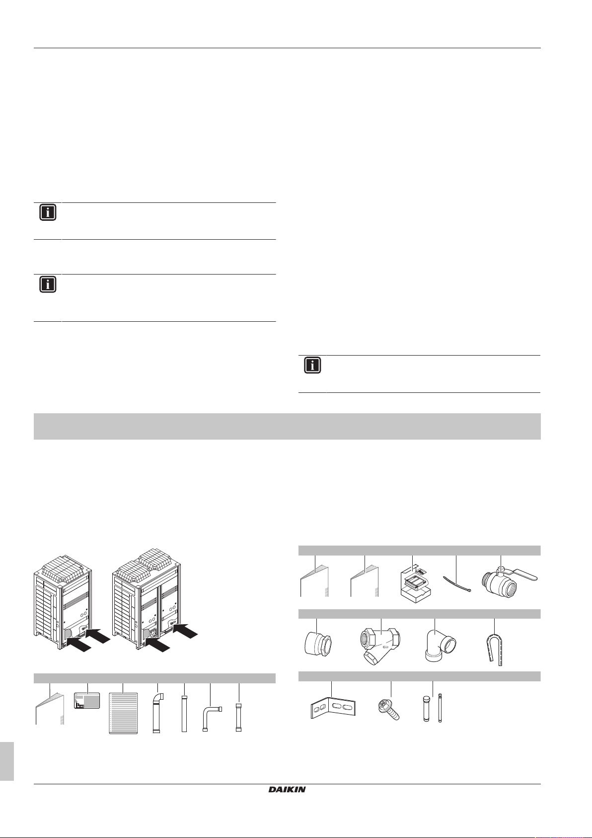
2.1.1 To remove the accessories from the outdoor unit
Make sure that all accessories are available in the unit.
f Liquid side accessory pipe
g Liquid side accessory pipes
2.2 Indoor unit
2.2.1 To remove the accessories from the indoor unit
Installation and operation manual
a General safety precautions
b Fluorinated greenhouse gases label
c Multilingual fluorinated greenhouse gases label
d Gas side accessory pipe
e Gas side accessory pipe
6
a General safety precautions
b Installation manual and operation manual (panel 3)
c User interface (panel 3)
d Tie wraps (panel 3)
e Shut-off valves (panel 3)
SERHQ020~032BAW1 + SEHVX20~64BAW
Split packaged air-cooled water chiller
4P508019-1D – 2019.11
3 About the units and options
43
–5
0
0 5 20 25
LWE
T
A
A B
0
35
25
5
–15
5 (EWC) 20 25 35 50
LWC
T
A
A B
RC
RT1M1RT2M2RT3
M3
FC1 FC2 FC3
a c e f
f
g g g
h
db
f Threaded connection (panel 3) (1× for SEHVX20+32BAW,
2× for SEHVX40+64BAW)
g Filter (panel 3)
h Elbow (panel 3)
i Black grommet (2×)
j L-shaped support (2×)
k M5 screws (3×)
l Accessory pipes (Ø12.7→Ø9.52 and Ø25.4→Ø28.6)
3 About the units and options
3.1 Identification
3.1.1 About the outdoor unit
SERHQ outdoor units are designed for outdoor installation and are
meant to be combined with SEHVX indoor units.
The outdoor units are designed to work in heating mode at ambient
temperatures from –15°C WB to 35°CWB and in cooling mode at
ambient temperatures from –5°CDB to 43°CDB.
3.1.2 About the indoor unit
This installation manual concerns the inverter heat pump chilling unit
with separate hydro module. The unit is intended for indoor
installation and can be combined with VRV outdoor units
(SERHQ020+032BAW1) for air conditioning purposes, or it can be
used for supplying water for process cooling applications.
The units are available in 4 standard sizes with nominal capacities
ranging from 16.8 to 63 kW.
The unit is designed to work in heating mode at ambient
temperatures from –15°C to 35°C and in cooling mode at ambient
temperatures from –5°C to 43°C.
The main component is the water heat exchanger.
The indoor unit is connected to the outdoor unit by field refrigerant
piping and the compressor in the outdoor unit circulates refrigerant
into the heat exchangers.
▪ In cooling mode, the refrigerant transports the heat taken from the
water heat exchanger to the air heat exchanger where the heat is
released to the air.
▪ In heating mode, the refrigerant transports the heat taken from the
air heat exchanger to the water heat exchanger where the heat is
released to the water.
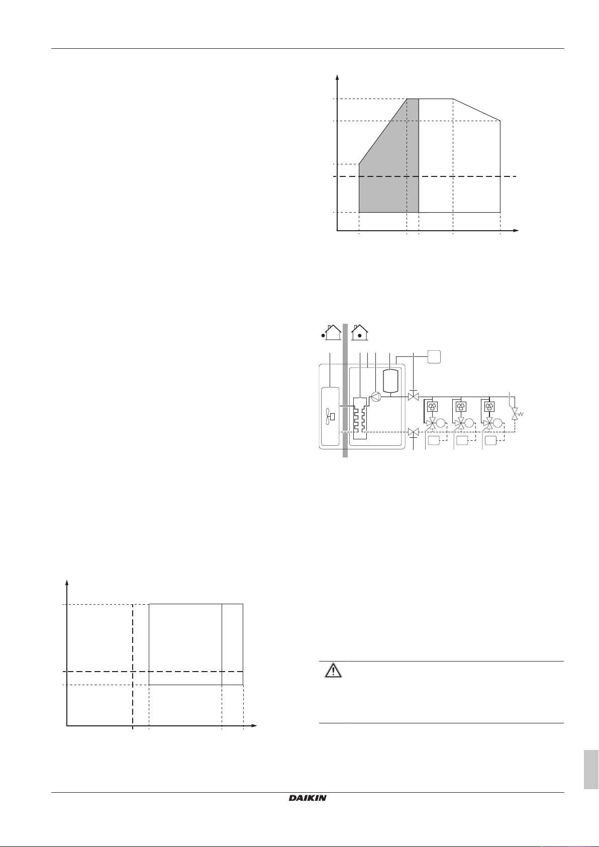
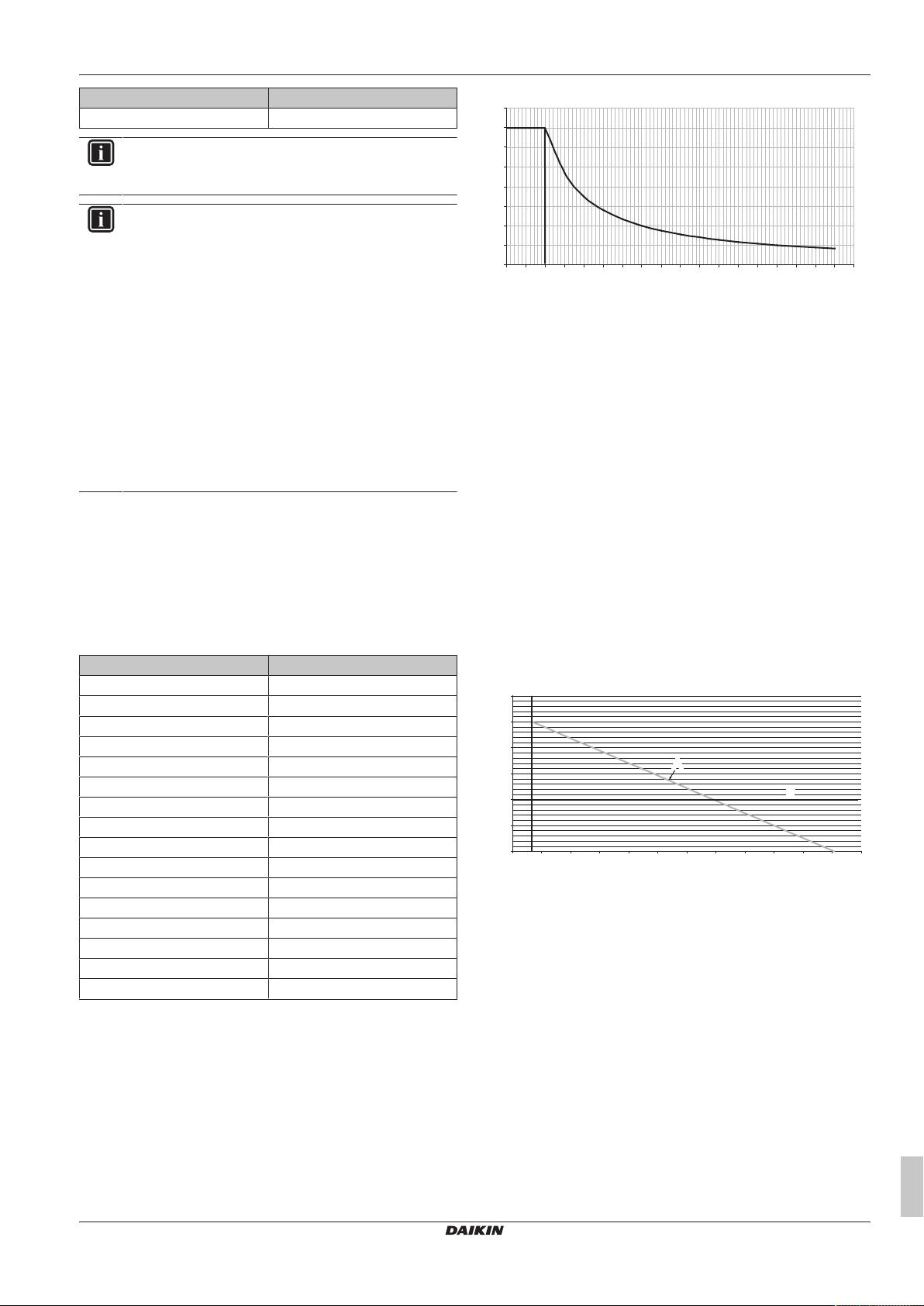
3.1.3 Operation range
Heating
TAAmbient temperature (°CDB)
LWC Leaving water condenser temperature (°C)
EWC Entering water condenser temperature (°C)
A Pull up area
B Standard water operation range
3.2 System layout
a Outdoor unit
b Indoor unit
c Plate heat exchanger
d Pump
e Expansion vessel
f Shut-off valve
g Motorized valve
h Bypass valve
FC1…3 Fancoil unit (field supply)
RC User interface
RT1…3 Room thermostat
Cooling
SERHQ020~032BAW1 + SEHVX20~64BAW
Split packaged air-cooled water chiller
4P508019-1D – 2019.11
TAAmbient temperature (°CDB)
LWE Leaving water evaporator temperature (°C)
A Standard water operation range
B Pull down area
4 Preparation
4.1 Preparing the installation site
4.1.1 Installation site requirements of the outdoor unit
CAUTION
Appliance NOT accessible to the general public, install it in
a secured area, protected from easy access.
This unit is suitable for installation in a commercial and
light industrial environment.
4.1.2 Installation site requirements of the indoor unit
Mind the spacing guidelines. See the "Technical data" chapter.
Installation and operation manual
7
4 Preparation
G
L
G1
L2
G2
L1
1
2
CAUTION
Appliance not accessible to the general public, install it in a
secured area, protected from easy access.
This unit, both indoor and outdoor, is suitable for
installation in a commercial and light industrial
environment.
4.2 Preparing refrigerant piping
4.2.1 Refrigerant piping requirements
NOTICE
The piping and other pressure-containing parts shall be
suitable for refrigerant. Use phosphoric acid deoxidised
seamless copper for refrigerant.
▪ Foreign materials inside pipes (including oils for fabrication) must
be ≤30mg/10m.
▪ Temper grade: use piping with temper grade in function of the
pipe diameter as listed in table below.
Pipe Ø Temper grade of piping material
≤15.9mm O (annealed)
≥19.1mm 1/2H (half hard)
▪ All piping lengths and distances have been taken into
consideration (see About the piping length in the installer
reference guide).
▪ The pipe thickness of the refrigerant piping shall comply with the
applicable legislation. The minimal pipe thickness for R410A
piping must be in accordance with the table below.
Pipe Ø Minimal thickness t
6.4mm/9.5mm/12.7mm 0.80mm
15.9mm 0.99mm
19.1mm/22.2mm 0.80mm
28.6mm 0.99mm
34.9mm 1.21mm
41.3mm 1.43mm
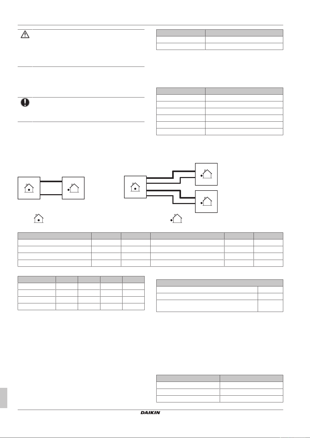
4.2.2 To select the piping size
Determine the proper size using the following tables and reference
figure (only for indication).
Indoor unit Outdoor unit
▪ Piping connection sizes
Indoor unit Gas Liquid Outdoor unit Gas Liquid
SEHVX20BAW Ø25.4mm Ø12.7mm 1× SERHQ020BAW1 Ø22.2mm Ø9.52mm
SEHVX32BAW Ø25.4mm Ø12.7mm 1× SERHQ032BAW1 Ø28.6mm Ø12.7mm
SEHVX40BAW Ø25.4mm Ø12.7mm 2× SERHQ020BAW1 Ø22.2mm Ø9.52mm
SEHVX64BAW Ø25.4mm Ø12.7mm 2× SERHQ032BAW1 Ø28.6mm Ø12.7mm
▪ Field piping sizes
Indoor unit G/G1 L/L1 G2 L2
SEHVX20BAW Ø28.6mm Ø9.52mm — —
SEHVX32BAW Ø28.6mm Ø12.7mm — —
SEHVX40BAW Ø28.6mm Ø9.52mm Ø28.6mm Ø9.52mm
SEHVX64BAW Ø28.6mm Ø12.7mm Ø28.6mm Ø12.7mm
If the hydro module connections do not match the diameter of the
specified piping requirements, the piping diameter requirements
must be met using reducers/expanders (field supply) on the hydro
module connections.
If the indoor unit connections do not match the diameter of the
specified piping requirements, the piping diameter requirements
must be met using reducers/expanders (field supply) on the indoor
unit connections.
Other diameters (mm sizes) can also be used if the required pipe
sizes (inch sizes) are not available, taking the following into account:
▪ select the pipe size nearest to the required size,
▪ use the suitable adapters for the change-over from inch to mm
pipes (field supply).
Installation and operation manual
8
4.2.3 About the piping length
Maximum piping length and height difference
Maximum allowable piping length 30m
Height difference between indoor and outdoor unit <10m
Height difference between outdoor unit 1 and outdoor
unit 2 (if applicable)
0m
4.3 Preparing water piping
4.3.1 To check the water volume and expansion vessel pre-pressure
The unit has an expansion vessel of 12 litre with a default prepressure of 1bar.
See the installer and user reference guide for more information.
Minimum water volume
Model Minimum total water volume (l)
20 76
32 110
40 152
SERHQ020~032BAW1 + SEHVX20~64BAW
Split packaged air-cooled water chiller
4P508019-1D – 2019.11
Model Minimum total water volume (l)
0.0
0.5
1.0
1.5
2.0
2.5
3.0
3.5
4.0
0 0.5 1 1.5 2 2.5 3 3.5 4 4.5 5 5.5 6 6.5 7 7.5 8 8.5
9
a
b
0
0.5
1
1.5
2
2.5
3
0 50 100 150 200 250 300 350 400 450 500 550 600
A
B
33
b
a
64 220
INFORMATION
In critical processes, or in rooms with a high heat load,
extra water might be required.
INFORMATION
The temperature step difference can be modified using
settings [A‑02] and [F‑00]. This has an impact on the
minimum water volume required when the unit operates in
cooling.
By default, the unit is set to have a water temperature
difference of 3.5 K which allows it to operate with the
minimum volume mentioned in the previous table.
However, if a smaller temperature differential is set, as in
the case of process cooling applications where
temperature fluctuations must be avoided, a larger
minimum water volume will be required.
To ensure proper operation of the unit when changing the
values of setting [F‑00] (for cooling mode), the minimum
water volume has to be corrected. If this volume exceeds
the range allowed in the unit, an additional expansion
vessel or a buffer tank must be installed in the field piping.
Example:
To illustrate the impact on the system when modifying the setting
[F‑00], we will consider a unit with a minimum allowable water
volume of 66l. The unit is installed 5m below the highest point in
the water circuit.
Assuming that the setting [F‑00] is changed from 5°C (default value)
to 0°C. From the below table we see that 5°C corresponds to a
temperature differential of 3.5K and 0°C to 1K, which is actually the
lowest value we can set.
[F‑00] value (°C) Temperature differential (K)
0 1
1 1.5
2 2
3 2.5
4 3
5 3.5
6 4
7 4.5
8 5
9 5.5
10 6
11 6.5
12 7
13 7.5
14 8
15 8.5
4 Preparation
a Water volume correction factor
b Temperature differential (K)
When multiplying 64 l by the correction factor, we get 224l, which
will be the minimum water volume allowed in the installation if a
temperature differential of 1K is used.
Now it is very important to check that for the height difference of the
system, the volume in the system is less than the maximum allowed
value at that pre-pressure (Pg). If we take a look at the curve, for
1bar of pre-pressure, the maximum volume allowed is 350l.
The total volume in the system will definitely be larger after adding
the internal volume of the unit. In this case, some pre-pressure can
be applied or an additional expansion vessel or buffer tank must be
installed in the field piping.
The default value of pre-pressure (Pg) is for a height difference of
7m.
If the height difference of the system is lower than 7 m AND the
volume in the system is less than the maximum allowed value at that
pre-pressure (Pg) (see graph), then NO pre-pressure (Pg)
adjustment is required.
Maximum water volume
Use the following graph to determine the maximum water volume for
the calculated pre-pressure.
a Pre-pressure (bar)
b Maximum water volume (l)
A System
B Default
If the total water volume in the entire circuit exceeds the maximum
allowed water volume (see graph), an additional expansion vessel
must be installed in the field piping.
The water volume correction factor according to the curve shown in
the below graph is 3.5; this means that the minimum volume will be
3.5 times larger.
Correction factor curve for minimum water volume
SERHQ020~032BAW1 + SEHVX20~64BAW
Split packaged air-cooled water chiller
4P508019-1D – 2019.11
4.4 Preparing electrical wiring
4.4.1 Safety device requirements
The power supply must be protected with the required safety
devices, i.e. a main switch, a slow blow fuse on each phase and an
earth leakage protector in accordance with the applicable legislation.
Selection and sizing of the wiring should be done in accordance with
the applicable legislation based on the information mentioned in the
table below.
Installation and operation manual
9
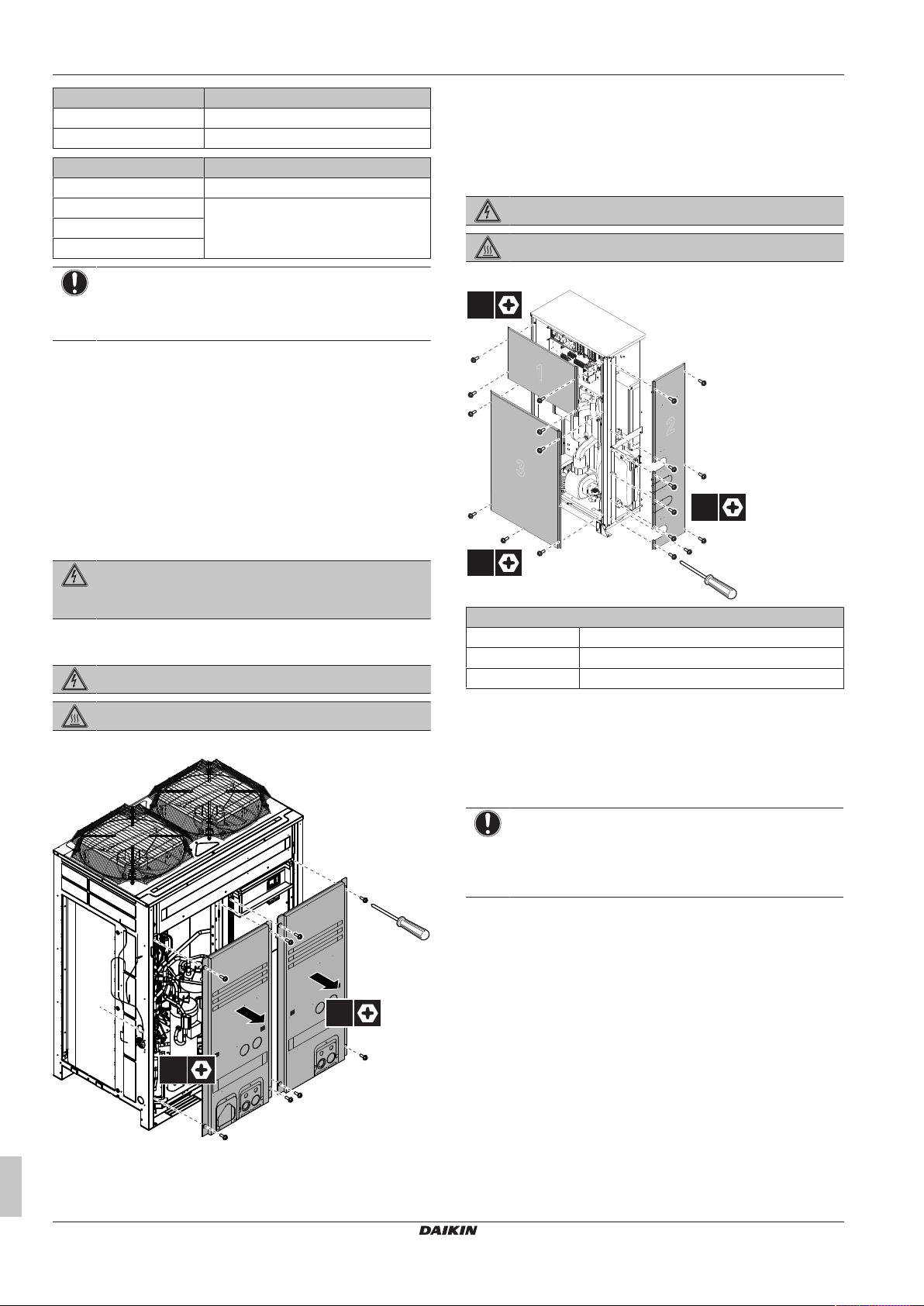
5 Installation
4×
4×
1
3
2
10×
5×
4×
Outdoor unit Recommended fuses
SERHQ020BAW1 32A
SERHQ032BAW1 40A
Indoor unit Recommended fuses
SEHVX20BAW 6A
SEHVX32BAW 10A
SEHVX40BAW
SEHVX64BAW
NOTICE
When using residual current operated circuit breakers, be
sure to use a high-speed type 300 mA rated residual
operating current.
5 Installation
5.1 Opening the units
5.1.1 About opening the units
At certain times, you have to open the unit. Example:
▪ When connecting the electrical wiring
▪ When maintaining or servicing the unit
For service purposes, the pushbuttons on the main PCB need to be
accessed. To access these pushbuttons, the electrical component
box cover does not need to be opened. See "6.1.3To access the
field setting components"[422].
5.1.3 To open the indoor unit
DANGER: RISK OF ELECTROCUTION
DANGER: RISK OF BURNING
To gain access to the unit, front plates need to be opened as follows:
DANGER: RISK OF ELECTROCUTION
Do NOT leave the unit unattended when the service cover
is removed.
5.1.2 To open the outdoor unit
DANGER: RISK OF ELECTROCUTION
DANGER: RISK OF BURNING
To gain access to the unit, front plates need to be opened as follows:
Panel
1 Electrical parts of the indoor unit
2 Indoor unit (side panel)
3 Indoor unit (front panel)
Once the front plates open, the electrical component box can be
accessed. See "5.1.5 To open the electrical component box of the
indoor unit"[411].
5.1.4 To open the electrical component box of the outdoor unit
NOTICE
Do NOT apply excessive force when opening the
electronic component box cover. Excessive force can
deform the cover, resulting in entering of water to cause
equipment failure.
Once the front plates open, the electrical component box can be
accessed. See "5.1.4 To open the electrical component box of the
outdoor unit"[410].
Installation and operation manual
10
SERHQ020~032BAW1 + SEHVX20~64BAW
Split packaged air-cooled water chiller
4P508019-1D – 2019.11
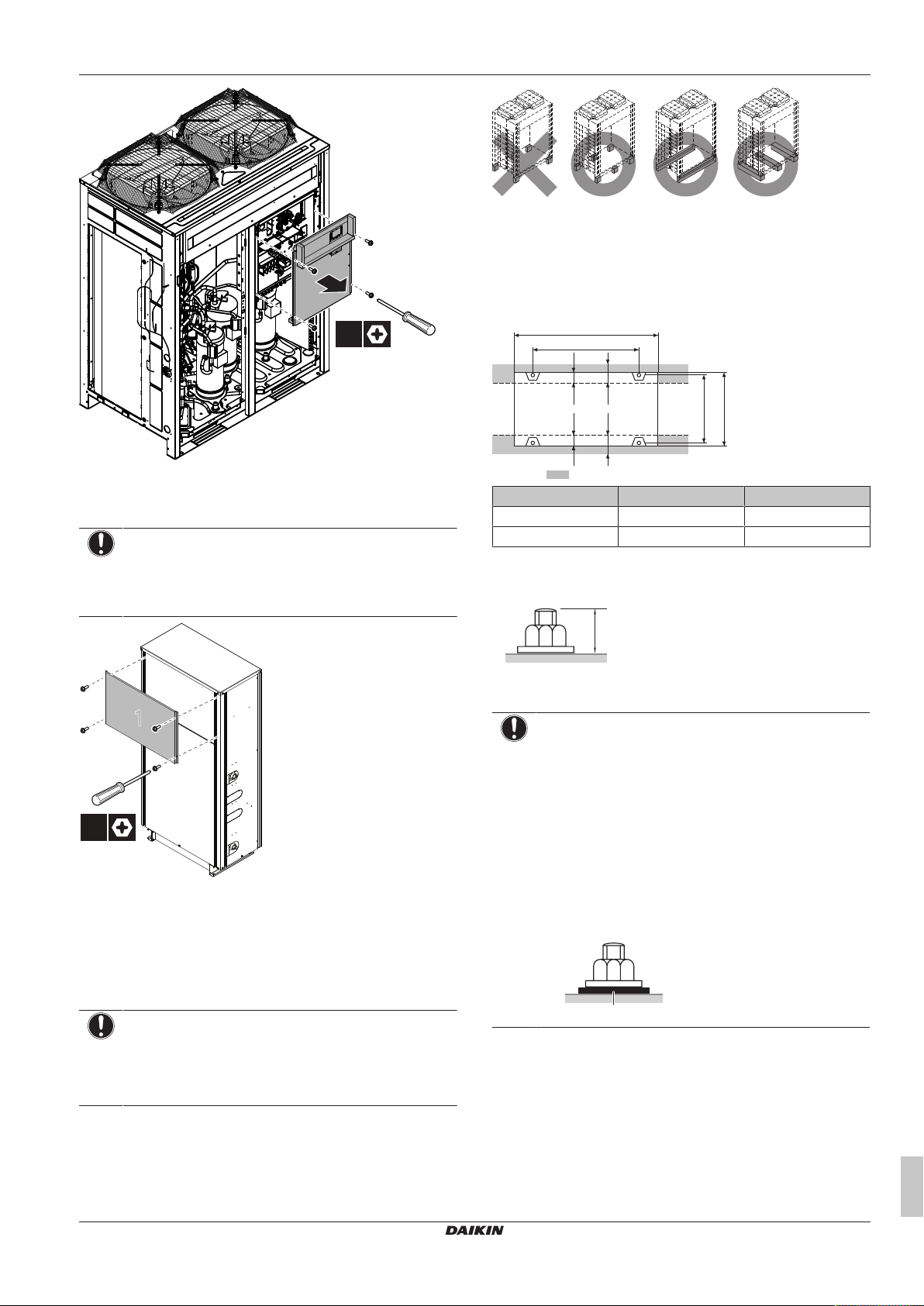
4×
5.1.5 To open the electrical component box of
1
4×
722-737
≥67≥67
765
6767
A
B
20 mm
a
the indoor unit
NOTICE
Do NOT apply excessive force when opening the
electronic component box cover. Excessive force can
deform the cover, resulting in entering of water to cause
equipment failure.
5 Installation
X Not allowed
O Allowed
▪ The height of the foundation must at least be 150mm from the
floor. In heavy snowfall areas, this height should be increased,
depending on the installation place and condition.
▪ The preferred installation is on a solid longitudinal foundation
(steel beam frame or concrete).
Minimum foundation
Outdoor unit A B
SERHQ020 930 792
SERHQ032 1240 1102
▪ Fasten the unit in place using four foundation bolts M12. It is best
to screw in the foundation bolts until their length remains 20 mm
above the foundation surface.
5.2 Mounting the outdoor unit
5.2.1 To provide the installation structure
Make sure the unit is installed level on a sufficiently strong base to
prevent vibration and noise.
NOTICE
▪ When the installation height of the unit needs to be
increased, do NOT use stands to only support the
corners.
▪ Stands under the unit must be at least 100mm wide.
5.2.2 To provide drainage
NOTICE
▪ Prepare a water drainage channel around the
foundation to drain waste water from around the unit.
▪ If the unit is to be installed on a roof, check the strength
of the roof and its drainage facilities first.
▪ If the unit is to be installed on a frame, install the
waterproofing board within a distance of 150mm under
the unit in order to prevent infiltration of water coming
from under the unit.
▪ When installed in a corrosive environment, use a nut
with plastic washer (a) to protect the nut tightening part
from rust.
5.3 Mounting the indoor unit
5.3.1 To provide the installation structure
Make sure the unit is installed level on a sufficiently strong base to
prevent vibration and noise.
SERHQ020~032BAW1 + SEHVX20~64BAW
Split packaged air-cooled water chiller
4P508019-1D – 2019.11
Installation and operation manual
11
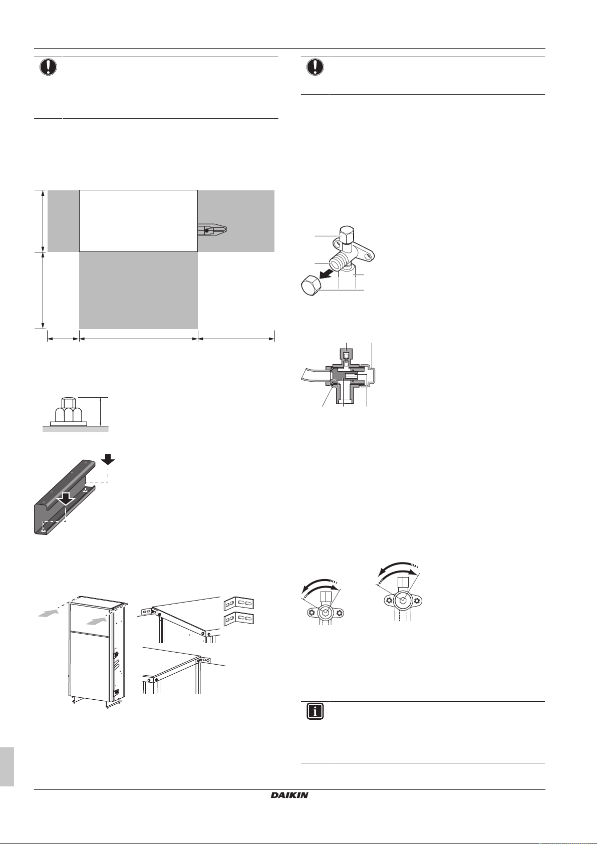
5 Installation
766.5 500200
396500
(mm)
20 mm
b
a
c
d
a
b
a b
cde
NOTICE
▪ When the installation height of the unit needs to be
increased, do NOT use stands to only support the
corners.
▪ Stands under the unit must be at least 100mm wide.
▪ The unit must be mounted against the wall.
▪ The unit must be fixed to prevent it from tilting.
▪ The preferred installation is on a solid longitudinal foundation
(steel beam frame or concrete).
▪ Observe the minimum installation space requirements.
NOTICE
Use the proper kind of screw for the type of wall or
foundation material where the unit will be fixed to.
5.4 Connecting the refrigerant piping
5.4.1 Using the stop valve and service port
To handle the stop valve
Take the following guidelines into account:
▪ The stop valves are factory closed.
▪ The following illustrations show each part required in handling the
valve.
a Service port and service port cover
b Stop valve
c Field piping connection
d Stop valve cover
▪ Fasten the unit in place using four foundation bolts M12. It is best
to screw in the foundation bolts until their length remains 20 mm
above the foundation surface.
▪ Fasten the unit to the floor using the holes in the bottom beams.
▪ Fasten the unit to the wall using the 2 accessory L-shaped
supports to prevent it from falling over. The supports can be fixed
to the top panel of the hydro module (2× M5 screws on either side,
but one screw is already mounted on the right side of the top
plate).
a Attach one L-shaped support to the left side of the top plate
using 2screws from the accessory bag
b Attach the other L-shaped support to the right side of the
top plate using 1screw from the accessory bag and
1screw that is already attached to the unit
a Service port
b Stop valve cover
c Hexagon hole
d Shaft
e Seal
▪ Keep both stop valves open during operation.
▪ Do NOT apply excessive force to the stop valve. Doing so may
break the valve body.
To open/close the stop valve
1 Remove the stop valve cover.
2 Insert a hexagon wrench (liquid side: 4 mm, gas side: 8mm)
into the stop valve and turn the stop valve:
Counterclockwise to open.
Clockwise to close.
3 When the stop valve CANNOT be turned any further, stop
turning.
4 Install the stop valve cover.
Result: The valve is now open/closed.
INFORMATION
▪ The SERHQ020 supports Ø22.2 field piping on the
accessory pipe supplied with the unit.
▪ The SERHQ032 supports Ø28.6 field piping on the
accessory pipe supplied with the unit.
Installation and operation manual
12
SERHQ020~032BAW1 + SEHVX20~64BAW
Split packaged air-cooled water chiller
4P508019-1D – 2019.11
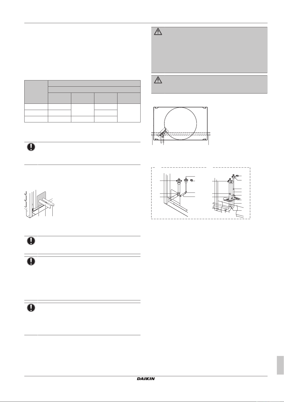
5 Installation
a b c
a b c
c
b
h
f
d
h
a
c
b
g
h
ih
j
k
h
h
h
e
i
a
A B
To handle the service port
▪ Always use a charge hose equipped with a valve depressor pin,
since the service port is a Schrader type valve.
▪ After handling the service port, make sure to tighten the service
port cover securely. For the tightening torque, refer to the table
below.
▪ Check for refrigerant leaks after tightening the service port cover.
Tightening torques
Stop valve
size (mm)
Ø9.5 5.4~6.6 4mm 13.5~16.5 11.5~13.9
Ø12.7 8.1~9.9 18.0~22.0
Ø25.4 27.0~33.0 8mm 22.5~27.5
Tightening torque N•m (turn clockwise to close)
Shaft
Valve body Hexagonal
wrench
Cap (valve
lid)
Service
port
5.4.2 To connect the refrigerant piping to the outdoor unit
NOTICE
All field piping must be installed by a licensed refrigeration
technician and must comply with the relevant local and
national regulations.
Seal the piping and wiring intake holes using sealing material (field
supply), otherwise the capacity of the unit will drop and small
animals may enter the machine.
Example: passing piping out through the front
WARNING
Take sufficient precautions in case of refrigerant leakage. If
refrigerant gas leaks, ventilate the area immediately.
Possible risks:
▪ Excessive refrigerant concentrations in a closed room
can lead to oxygen deficiency.
▪ Toxic gas may be produced if refrigerant gas comes
into contact with fire.
WARNING
NEVER directly touch any accidental leaking refrigerant.
This could result in severe wounds caused by frostbite.
The refrigerant piping can be installed from the front or from the side
of the unit (when taken out from the bottom) as shown in the figure.
a Left-side connection
b Front connection
c Right-side connection
a Plug the grey areas (piping routed through the front panel)
b Gas side piping
c Liquid side piping
NOTICE
After all the piping has been connected, make sure there is
no gas leak. Use nitrogen to perform a gas leak detection.
NOTICE
▪ Be sure to use the supplied accessory pipes when
carrying out piping work in the field.
▪ Be sure that the field installed piping does not touch
other pipes, the bottom panel or side panel. Especially
for the bottom and side connection, be sure to protect
the piping with suitable insulation, to prevent it from
coming into contact with the casing.
NOTICE
Use a 2-stage vacuum pump with a non-return valve that
can evacuate to a gauge pressure of −100.7 kPa
(−1.007 bar)(5 Torr absolute). Make sure the pump oil
does not flow oppositely into the system while the pump is
not working.
SERHQ020~032BAW1 + SEHVX20~64BAW
Split packaged air-cooled water chiller
4P508019-1D – 2019.11
A For front connection, remove the stop valve cover to
connect the refrigerant piping.
B For side connection, remove the knockouts in the bottom
frame and route the piping under the bottom frame.
a Gas pipe stop valve
b Liquid pipe stop valve
c Service port for adding refrigerant
d Gas side accessory pipe (1)
e Gas side accessory pipe (2)
f Liquid side accessory pipe (1)
g Liquid side accessory pipe (2)
h Brazing
i Gas side piping (field supply)
j Liquid side piping (field supply)
k Open the knockout holes with a hammer
Cutting the gas side accessory pipe
When connecting the refrigerant piping from the side, cut the gas
side accessory pipe as shown in the figure.
Installation and operation manual
13
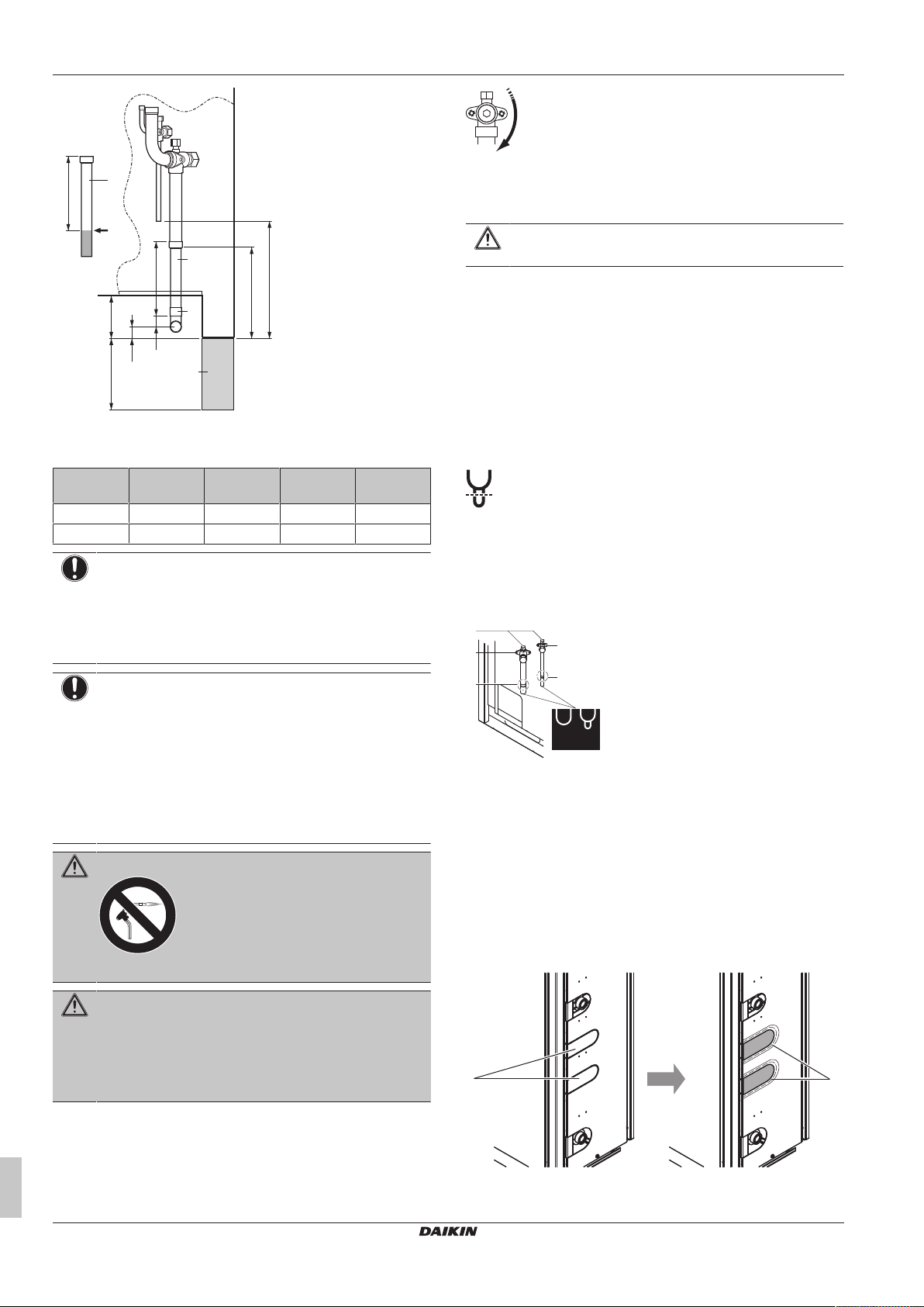
5 Installation
A
AB
C
D
a
b
a
c
d
25
150 90
a
b
c
b
c
B
A
a
b
a Gas side accessory pipe
b Cut here
c Gas side piping (field supply)
d Unit base
Outdoor
unit
SERHQ020 156 23 192 247
SERHQ032 150 29 192 251
NOTICE
▪ When connecting the piping on site, be sure to use the
▪ Make sure the onsite piping does not come into contact
A B C D
accessory piping.
with other piping, the bottom frame or side panels of
the unit.
2 Connect a charge hose to service ports of all stop valves.
3 Recover gas and oil from the pinched piping by using a
recovery unit.
CAUTION
Do not vent gases into the atmosphere.
4 When all gas and oil is recovered from the pinched piping,
disconnect the charge hose and close the service ports.
5 If the pinched piping lower part looks like detail A in the figure
below, perform the last 2steps of this procedure.
6 If the pinched piping lower part looks like detail B in the figure
below, perform the last 3steps of this procedure.
7 Cut off the lower part of the smaller pinched piping with an
appropriate tool (e.g. a pipe cutter, a pair of nippers, …) so that
a cross-section is open, allowing remaining oil to drip out in
case the recovery was not complete. Wait until all oil has
dripped out.
8 Cut the pinched piping off with a pipe cutter just above the
brazing point or just above the marking if there is no brazing
point.
9 Wait until all oil is dripped out in case the recovery was not
complete, and only then proceed with connection of the field
piping.
NOTICE
Precautions when making knockout holes:
▪ Avoid damaging the casing.
▪ After making the knockout holes, we recommend you
remove the burrs and paint the edges and areas
around the edges using repair paint to prevent rusting.
▪ When passing electrical wiring through the knockout
holes, wrap the wiring with protective tape to prevent
damage.
WARNING
Never remove the pinched piping by brazing.
WARNING
Any gas or oil remaining inside the stop valve may blow off
the pinched piping.
Failure to observe the instructions in procedure below
properly may result in property damage or personal injury,
which may be serious depending on the circumstances.
Use the following procedure to remove the pinched piping:
1 Remove the valve lid and make sure that the stop valves are
fully closed.
Installation and operation manual
14
5.4.3 To connect the refrigerant piping to the
▪ For the SEHVX20+32BAW, remove the top knockout hole in the
side service plate and add the grommet (accessory) to cover any
burrs. For the SEHVX40+64BAW, remove both top and bottom
knockout holes in the side service plate and add the grommets
(accessory) to cover any burrs.
a Service port
b Stop valve
c Point of pipe cutting just above brazing point or above
marking
A+B Pinched piping
indoor unit
a Knockout hole
b Grommet
SERHQ020~032BAW1 + SEHVX20~64BAW
Split packaged air-cooled water chiller
4P508019-1D – 2019.11
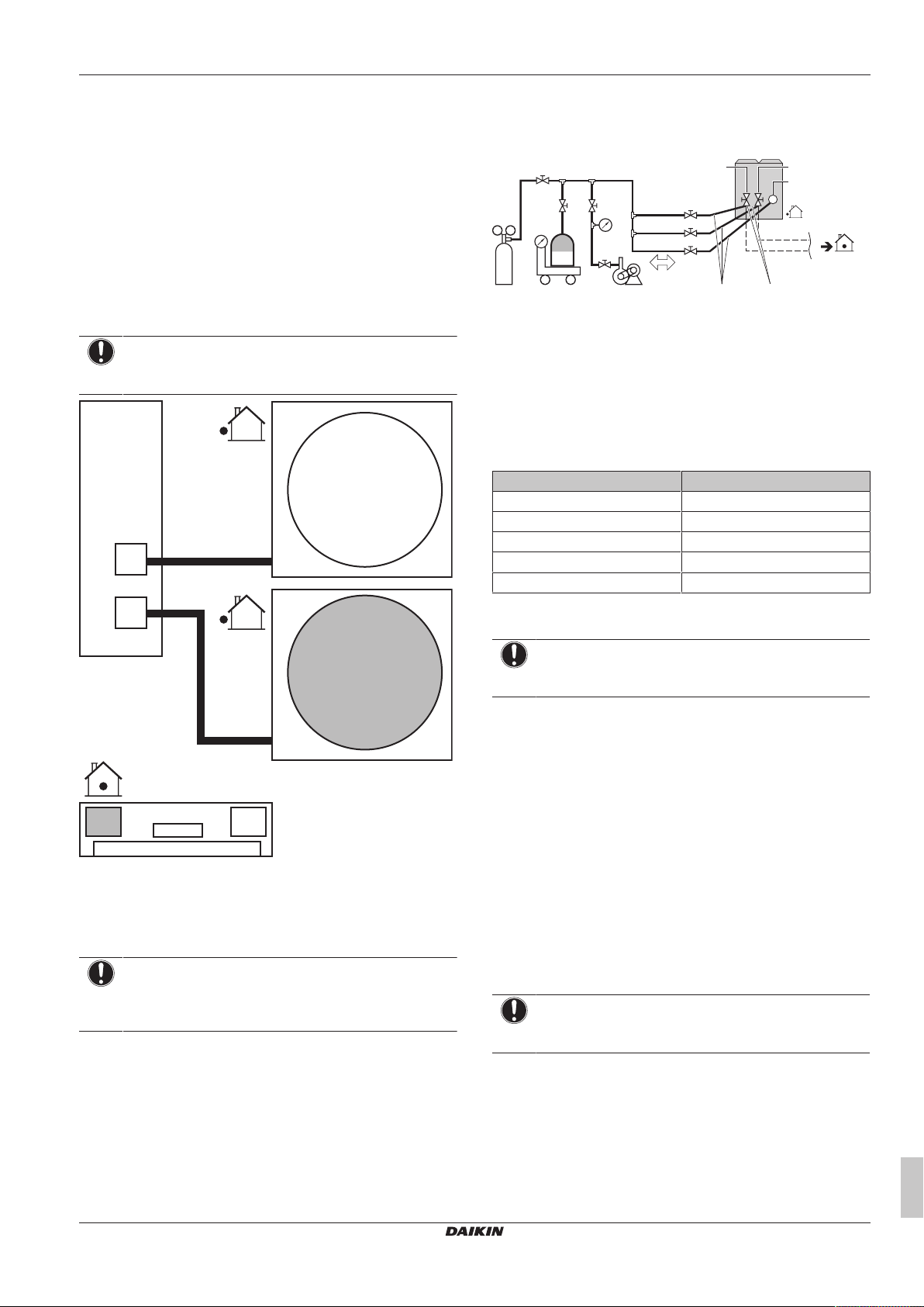
5 Installation
VRV
C1
VRV
C2
f
e
g
C2
g
C1
C1
C2
d
d
a
b
c
f
i
h
a
b
d
c
e
k
l
m
j
g
▪ First cut off the refrigerant liquid piping inside the unit
approximately 7 cm before the clamp and the refrigerant gas
piping 4cm before the clamp. This is necessary in order to avoid
the piping cutter tool from interfering with the piping. Remove any
burrs from the piping.
▪ Use accessory pipes to connect field refrigerant piping to the
piping connections on the indoor unit. For SEHVX20BAW, after
cutting off the end of both the liquid and gas refrigerant piping,
braze accessory pipe 1 to the liquid connection and accessory
pipe 2 to the gas connection. For SEHVX32BAW, after cutting off
the end of both the liquid and gas refrigerant piping, braze the field
piping directly to the liquid connection and accessory pipe 2 to the
gas connection. For SEHVX40BAW, perform the procedure for
SEHVX20BAW twice. For SEHVX64BAW, perform the procedure
for SEHVX32BAW twice.
NOTICE
After brazing, fix the pipes to the unit using the clamps in
the pipe supports.
5.5 Checking the refrigerant piping
5.5.1 Checking refrigerant piping: Setup
a Pressure reducing valve
b Nitrogen
c Weighing scales
d R410A refrigerant tank (siphon system)
e Vacuum pump
f Charge hose
g Service port for adding refrigerant
h Liquid line stop valve
i Gas line stop valve
j Stop valve service port
k Valve A
l Valve B
m Valve C
Valve State of valve
Valve A Close
Valve B Open
Valve C Close
Liquid line stop valve Close
Gas line stop valve Close
5.5.2 To check for leaks: Pressure leak test
NOTICE
After all the piping has been connected, make sure there is
no gas leak. Use nitrogen to perform a gas leak detection.
1 Break the vacuum by pressurising with nitrogen gas to a gauge
pressure of 4.0 MPa (40 bar). Never set the gauge pressure
higher than the maximum operation pressure of the unit, i.e.
4.0MPa (40bar).
5.5.3 To perform vacuum drying
To remove all moisture from the system, proceed as follows:
1 Evacuate the system for at least 2 hours to a target vacuum of
a Indoor unit
b Outdoor unit 1
c Outdoor unit 2 (only in case of SEHVX40+64BAW)
d Refrigerant piping
e Pump
f Switchbox
g Evaporator
NOTICE
When installing the piping between the outdoor and indoor
units, also refer to the figure in "5.8.4To connect the power
supply and transmission cables"[420].
–100.7kPa (–1.007bar)(5Torr absolute).
2 Check that, with the vacuum pump turned off, the target
vacuum is maintained for at least 1 hour.
3 Should you fail to reach the target vacuum within 2 hours or
maintain the vacuum for 1 hour, the system may contain too
much moisture. In that case, break the vacuum by pressurising
with nitrogen gas to a gauge pressure of 0.05 MPa (0.5bar)
and repeat steps 1 to 3 until all moisture has been removed.
NOTICE
In case of SEHVX40+64BAW, perform the operations on
both units.
5.5.4 To insulate the refrigerant piping
SERHQ020~032BAW1 + SEHVX20~64BAW
Split packaged air-cooled water chiller
4P508019-1D – 2019.11
After finishing the leak test and vacuum drying, the piping must be
insulated. Take into account the following points:
▪ Be sure to insulate the liquid and gas piping (for all units).
▪ Use heat resistant polyethylene foam which can withstand a
temperature of 70°C for liquid piping and polyethylene foam which
can withstand a temperature of 120°C for gas piping.
Installation and operation manual
15
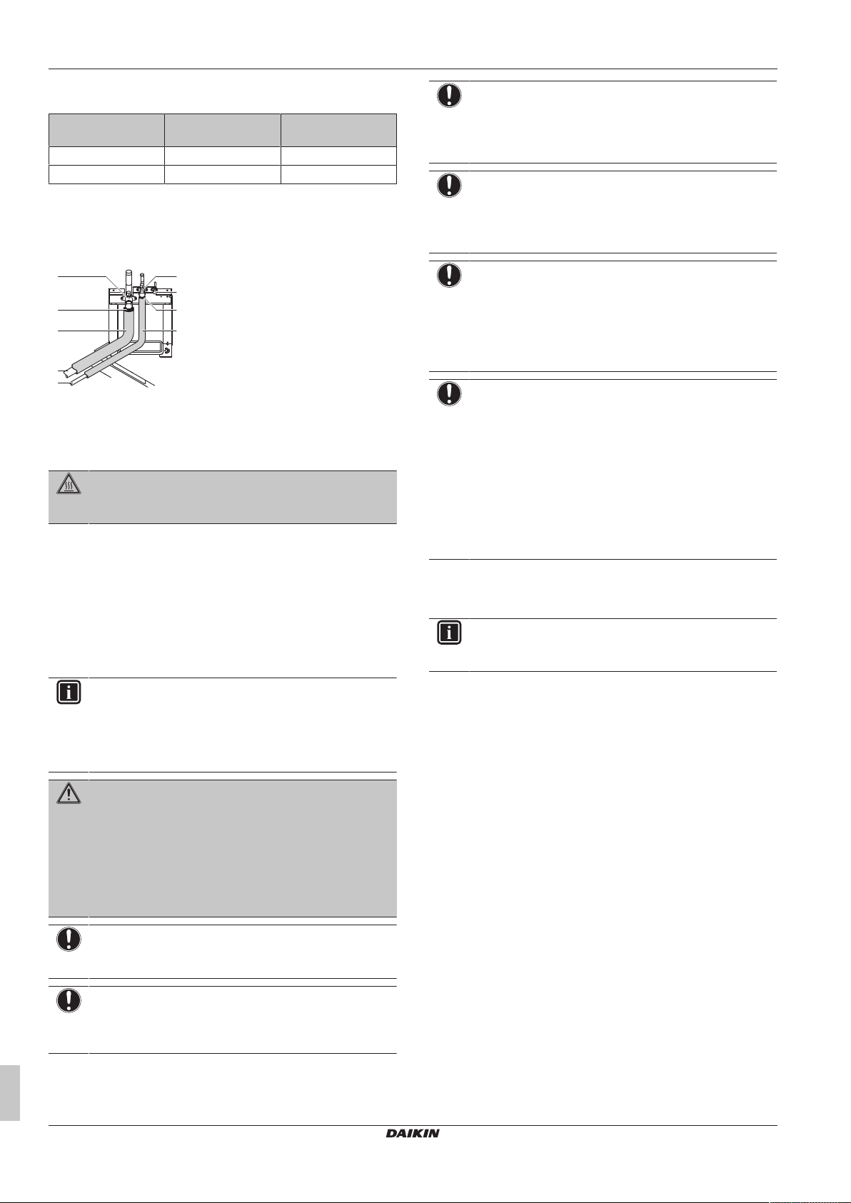
5 Installation
f
f
e
a
d
c
b
d
e
▪ Reinforce the insulation on the refrigerant piping according to the
installation environment.
Ambient
Humidity Minimum thickness
temperature
≤30°C 75% to 80% RH 15mm
>30°C ≥80% RH 20mm
▪ If there is a possibility that condensation on the stop valve might
drip down into the indoor unit through gaps in the insulation and
piping because the outdoor unit is located higher than the indoor
unit, this must be prevented by sealing up the connections. See
below figure.
a Gas line stop valve
b Liquid line stop valve
c Service port for adding refrigerant
d Sealing up treatment
e Insulation
f Piping between indoor and outdoor unit
DANGER: RISK OF BURNING
Be sure to insulate local pipes, as touching them can
cause burns.
5.6 Charging refrigerant
NOTICE
If operation is performed within 12 minutes after the indoor
and outdoor units are turned on, the H2P LED will be lit
and the compressor will not operate before communication
is established between outdoor unit(s) and indoor units.
NOTICE
Close the front panel before any refrigerant charge
operation is executed. Without the front panel attached the
unit cannot judge correctly whether it is operating properly
or not.
NOTICE
In case of maintenance and the system (outdoor unit+field
piping+indoor units) does not contain any refrigerant any
more (e.g., after refrigerant reclaim operation), the unit has
to be charged with its original amount of refrigerant (refer
to the nameplate on the unit) by pre-charging before the
automatic charging function can be started.
NOTICE
▪ The refrigerant charging port is connected to the piping
inside the unit. The unit's internal piping is already
factory charged with refrigerant, so be careful when
connecting the charge hose.
▪ After adding the refrigerant, do not forget to close the
lid of the refrigerant charging port. The tightening
torque for the lid is 11.5 to 13.9N•m.
▪ In order to ensure uniform refrigerant distribution, it
may take the compressor ±10 minutes to start up after
the unit has started operation. This is not a malfunction.
5.6.1 About charging refrigerant
5.6.3 To determine the additional refrigerant amount
Once vacuum drying is finished, additional refrigerant charging can
start.
INFORMATION
For final charge adjustment in a test laboratory, contact
5.6.2 Precautions when charging refrigerant
INFORMATION
Also read the precautions and requirements in the
following chapters:
▪ General safety precautions
▪ Preparation
WARNING
▪ Only use R410A as refrigerant. Other substances may
cause explosions and accidents.
▪ R410A contains fluorinated greenhouse gases. Its
global warming potential (GWP) value is 2087.5. Do
NOT vent these gases into the atmosphere.
▪ When charging refrigerant, always use protective
gloves and safety glasses.
NOTICE
If the power of some units is turned off, the charging
procedure cannot be finished properly.
NOTICE
Be sure to turn on the power 6 hours before operation in
order to have power running to the crankcase heater and
to protect the compressor.
Refrigerant type: R410A
Global warming potential (GWP) value: 2087.5
The additional refrigerant charge calculation is based on the liquid
piping size.
Formula:
R=(X
Example
SEHVX64BAW (indoor unit) + 2× SERHQ032BAW1 (outdoor unit)
R=(L1+L2)
5.6.4 To charge refrigerant
Pre-charging refrigerant
your dealer.
×0.059)+(X
Ø9.52
R Additional refrigerant to be charged [in kg and rounded off
X
1, 2
×0.12
Ø12.7
L1 Liquid pipe of circuit 1 (indoor → outdoor1)
L2 Liquid pipe of circuit 2 (indoor → outdoor2)
×0.12)
Ø12.7
to 1 decimal place]
Total length [m] of liquid piping size at Øa
1 Calculate the additional amount of refrigerant to be added using
the formula mentioned in "5.6.3 To determine the additional
refrigerant amount"[416].
2 Open valve C (valves A and B and the stop valves must be left
closed) and charge the refrigerant in liquid form via the liquid
side stop valve service port.
Installation and operation manual
16
3 Close valve C when the calculated amount for pre-charging is
reached.
SERHQ020~032BAW1 + SEHVX20~64BAW
Split packaged air-cooled water chiller
4P508019-1D – 2019.11
 Loading...