

Daikin FTYNV20AV1, FTYNV25AV1, FTYNV35AV1, FTYNV50AV1, FTYNV60AV1 Operation manuals
...
R410A Split Series
OWNER'S MANUAL
MODEL
FTYNV20AV1
FTYNV25AV1
FTYNV35AV1
FTYNV50AV1
FTYNV60AV1
RYNV20AV1
RYNV25AV1
RYNV35AV1
RYNV50AV1
RYNV60AV1

English
Disposal requirements
Your product and the batteries supplied with the controller are marked with this symbol.
This symbol means that electrical and electronic products and batteries shall not be mixed
with unsorted household waste. For batteries, a chemical symbol can be printed beneath
the symbol. This chemical symbol means that the battery contains a heavy metal above
a certain concentration. Possible chemical symbols are:
■
Do not try to dismantle the system yourself: the dismantling of the product, treatment of the refrigerant,
of oil and of other parts must be done by a qualified installer in accordance with relevant local and national
legislation. Units and waste batteries must be treated at a specialized treatment facility for re-use,
recycling and recovery. By ensuring correct disposal, you will help to prevent potential negative
consequences for the environment and human health. Please contact the installer or local authority
for more information.
Pb: lead (>0.004%)

Content
Operation Notices
Safety Precautions..................................................................................................1
Parts Name.............................................................................................................3
Installation Notice
Installation dimension diagram ...............................................................................4
Tools for installation................................................................................................ 5
Selection of installation location.............................................................................. 5
Requirements for electric connection ..................................................................... 6
Installation
Installation of indoor unit......................................................................................... 7
Installation of outdoor unit..................................................................................... 12
Vacuum pumping..................................................................................................15
Leakage detection ................................................................................................15
Check after installation .........................................................................................16
Test and operation
Test operation.......................................................................................................16
Attachment
Configuration of connection pipe .......................................................................... 17
English
Pipe expanding method ........................................................................................18
Screen Operation Guide
Buttons on remote controller................................................................................. 19
Introduction to icons on display screen................................................................. 19
Introduction to buttons on remote controller ......................................................... 20
Introduction to functions of combination buttons ..................................................23
Operation guide ....................................................................................................24
Replacement of batteries in remote controller ...................................................... 24
Emergency operation............................................................................................25
Maintenance
Cleaning and Maintenance ...................................................................................25
Malfunction
Malfunction analysis .............................................................................................28
Wiring.................................................................................................................... 31
Safety Precautions
• The precautions described herein are classified as WARNING and CAUTION. They both contain important information
regarding safety. Be sure to observe all precautions without fail.
• Meaning of WARNING and CAUTION notices
WARNING ..........Failure to follow these instructions properly may result in personal injury or loss of life.
CAUTION ...........Failure to observe these instructions properly may result in property damage or personal injury,
• The safety marks shown in this manual have the following meanings:
Be sure to follow the instructions. Be sure to establish an earth connection. Never attempt.
• After completing installation, conduct a trial operation to check for faults and explain to the customer how to operate
the air conditioner and take care of it with the aid of the operation manual.
• The English text is the original instruction. Other languages are translations of the original instructions.
• Ask your dealer or qualified personnel to carry out installation work.
Do not attempt to install the air conditioner yourself. Improper installation may result in water leakage, electric shocks or fire.
• Install the air conditioner in accordance with the instructions in this installation manual.
Improper installation may result in water leakage, electric shocks or fire.
• Be sure to use only the specified accessories and parts for installation work.
Failure to use the specified parts may result in the unit falling, water leakage, electric shocks or fire.
• Install the air conditioner on a foundation strong enough to withstand the weight of the unit.
A foundation of insufficient strength may result in the equipment falling and causing injury.
• Electrical work must be performed in accordance with relevant local and national regulations and with instructions
in this installation manual. Be sure to use a dedicated power supply circuit only.
Insufficiency of power circuit capacity and improper workmanship may result in electric shocks or fire.
• Use a cable of suitable length.
Do not use tapped wires or an extension lead, as this may cause overheating, electric shocks or fire.
• Make sure that all wiring is secured, the specified wires are used, and that there is no strain on the terminal
connections or wires.
Improper connections or securing of wires may result in abnormal heat build-up or fire.
• When wiring the power supply and connecting the wiring between the indoor and outdoor units, position the wires
so that the control box lid can be securely fastened.
Improper positioning of the control box lid may result in electric shocks, fire or over heating terminals.
• If refrigerant gas leaks during installation, ventilate the area immediately.
Toxic gas may be produced if the refrigerant comes into contact with fire.
• After completing installation, check for refrigerant gas leakage.
Toxic gas may be produced if the refrigerant gas leaks into the room and comes into contact with a source of fire, such as a fan heater,
stove or cooker.
• When installing or relocating the air conditioner, be sure to bleed the refrigerant circuit to ensure it is free of air,
and use only the specified refrigerant (R410A).
The presence of air or other foreign matter in the refrigerant circuit causes abnormal pressure rise, which may result in equipment damage and even
injury.
• During installation, attach the refrigerant piping securely before running the compressor.
If the compressor is not attached and the stop valve is open when the compressor is run, air will be sucked in, causing abnormal pressure in the
refrigeration cycle, which may result in equipment damage and even injury.
• During pump-down, stop the compressor before removing the refrigerant piping.
If the compressor is still running and the stop valve is open during pump-down, air will be sucked in when the refrigerant piping is removed,
causing abnormal pressure in the refrigeration cycle, which may result in equipment damage and even injury.
• Be sure to earth the air conditioner.
Do not earth the unit to a utility pipe, lightning conductor or telephone earth lead. Imperfect earthing may result in electric shocks.
• Be sure to install an earth leakage breaker.
Failure to install an earth leakage breaker may result in electric shocks or fire.
• Do not touch any electronic component or terminal when the machine is running, stopping or has been powered off
for less than 30 minutes to prevent the risk of electric shock!
which may be serious depending on the circumstances.
WARNING
English
1
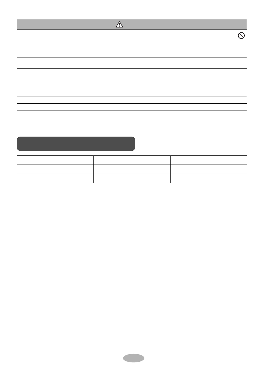
CAUTION
Working temperature range
• Do not install the air conditioner at any place where there is a danger of flammable gas leakage.
In the event of a gas leakage, build-up of gas near the air conditioner may cause a fire to break out.
• While following the instructions in this installation manual, install drain piping to ensure proper drainage and insulate
piping to prevent condensation.
Improper drain piping may result in indoor water leakage and property damage.
• Tighten the flare nut according to the specified method such as with a torque wrench.
If the flare nut is too tight, it may crack after prolonged use, causing refrigerant leakage.
• Make sure to provide for adequate measures in order to prevent that the outdoor unit be used as a shelter by small animals.
Small animals making contact with electrical parts can cause malfunctions, smoke or fire. Please instruct the customer to keep the area around the
unit clean.
• This appliance is intended to be used by expert or trained users in shops, in light industry and on farms,
or for commercial and household use by lay persons.
• Sound pressure level is less than 70 dB(A).
• NOTE: Motor ground only applies to the iron shell motor.
• This appliance is not intended for use by persons, including children, with reduced physical, sensory or mental
capabilities, or lack of experience and knowledge, unless they have been given supervision or instruction concerning
use of the appliance by a person responsible for their safety.
Children shall be supervised to ensure that they do not play with the appliance.
English
Maximum cooling 32/23 43/26
Indoor side DB/WB(°C) Outdoor side DB/WB(°C)
Maximum heating 27/- 24/18
● The operating temperature range (outdoor temperature) is 18 - 43°C for cooling
and -7 - 24°C for heating operation.
2
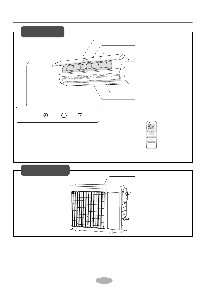
Parts Name
SLEEP
TIMER LIGHT X-FAN
MODE
SAVE
+
-
FAN
SWING
ON/OFFTURBO
air inlet
panel
filter
aux. button
horizontal louver
air outlet
display
remote controller
receiver
window
power
indicator
Timer
Indoor Unit
air inlet
handle
air outlet
Outdoor Unit
English
3
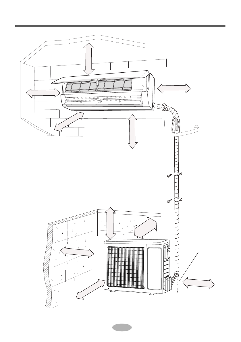
Installation dimension diagram
Drainage pipe
At least 250cm
At least 15cm
At least 50cm
At least 50cm
At least
30cm
At least 300cm
At least 200cm
Space to the obstruction
Space to the
obstruction
Space to the
obstruction
Space to the ceiling
Space to the floor
Space to the obstruction
Space to the obstruction
At least 30cm
At least 15cm
At least 15cm
Space to the wall
Space to the wall
Space to the wall
English
4
Tools for installation
● Please contact the local agent for installation.
● Don’t use unqualified power cord.
Note:
Basic requirement Indoor unit
Installing the unit in the following places
may cause malfunction. If it is
unavoidable, please consult the
local dealer:
1. The place with strong heat sources,
vapors, flammable or explosive gas,
or volatile objects spread in the air.
2. The place with high-frequency
devices (such as welding machine,
medical equipment).
3. The place near coast area.
4. The place with oil or fumes in the air.
5. The place with sulfureted gas.
6. Other places with special
circumstances.
7. The appliance shall not be installed in
the laundry.
1. There should be no obstruction near
air inlet and air outlet.
2. Select a location where the
condensation water can be dispersed
easily and won't affect other people.
3. Select a location which is convenient
to connect the indoor unit and near the
power socket.
4. Select a location which is out of reach
for children.
5. The location should be able to
withstand the weight of indoor unit and
won't increase noise and vibration.
6. The appliance must be installed 2.5m
above floor
7. Don't install the indoor unit right above
the electric appliance.
8. Please try your best to keep away
from fluorescent lamp.
Outdoor unit
1. Select a location where the noise and outflow air emitted by the outdoor unit will
not affect the neighborhood.
2. The location should be well ventilated and dry, in which the outdoor unit won't be
exposed directly to sunlight or strong wind.
3. The location should be able to withstand the weight of outdoor unit.
4. Make sure that the installation follows the requirements of installation dimension
diagram.
5. Select a location which is out of reach for children and far away from animals or
plants.If it is unavoidable, please add the fence for safety purpose.
1 Level meter 2 Screw driver 3 Impact drill
4 Drill head 5 Pipe expander 6 Torque wrench
7 Open-end wrench 8 Pipe cutter 9 Leakage detector
10 Vacuum pump 11 Pressure meter 12 Universal meter
13 Inner hexagon spanner 14 Measuring tape
Selection of installation location
5
English

Requirements for electric connection
Safety precaution
Grounding requirement
1. The electric safety regulations must be followed when installing the unit.
2. According to the local safety regulations, use qualified power supply circuit
and earth leakage circuit breaker.
3. Make sure the power supply matches with the requirement of air conditioner.
Unstable power supply or incorrect wiring may result in electric shock, fire hazard
or malfunction. Please install proper power supply cables before using the air
conditioner.
4. Properly connect the live wire, neutral wire and grounding wire of power socket.
5. Be sure to cut off the power supply before proceeding any work related to
electricity and safety.
6. Do not put through the power before finishing installation.
7. If the supply cord is damaged, it must be replaced by the manufacturer, its service
agent or similarly qualified persons in order to avoid hazard.
8. The temperature of refrigerant circuit will be high, please keep the interconnection
cable away from the copper tube.
9. The appliance shall be installed in accordance with national wiring regulations.
English
1. The air conditioner is the first class electric appliance. It must be properly
grounded with specialized grounding device by a professional. Please make sure
it is always grounded effectively, otherwise it may cause electric shock.
2. The yellow-green wire in air conditioner is grounding wire, which can't be used for
other purposes.
3. The grounding resistance should comply with national electric safety regulations.
4. The appliance must be positioned so that the plug is accessible.
5. An all-pole disconnection switch having a contact separation of at least 3mm in
all poles should be connected in fixed wiring.
6. Be sure to install an earth leakage breaker capable of handling maximum rated
current. (One that can handle higher harmonics.)
6
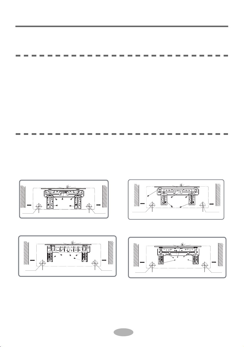
Installation of indoor unit
ø55
ø55
Left
Wall
Right
Mark in the middle of it Level meter
Wall
Space
to the
wall
above
150mm
(Rear piping hole) (Rear piping hole)
Space
to the
wall
above
150mm
20 and 25 class:
35 class:
Left
Wall
Right
Mark in the middle of it Level meter
Wall
Space
to the
wall
above
150mm
(Rear piping hole) (Rear piping hole)
Space
to the
wall
above
150mm
ø70mm ø70mm
60 class:
Left
Wall
Right
Mark in the middle of it Level meter
Wall
Space
to the
wall
above
150mm
(Rear piping hole)
(Rear piping hole)
Space
to the
wall
above
150mm
ø55mm
ø55mm
50 class:
Step one: choosing installation location
Recommend the installation location to the client and then confirm it with the client.
Step two: install wall-mounting frame
1. Hang the wall-mounting frame on the wall; adjust it in horizontal position with the
level meter and then point out the screws fixing holes on the wall.
2. Drill the screw fixing holes on the wall with impact drill (the specification of drill
head should be the same as the plastic expansion particle) and then fill the plastic
expansion particles in the holes.
3. Fix the wall-mounting frame on the wall with tapping screws (ST4.2X25TA) and
then check if the frame is firmly installed by pulling the frame. If the plastic
expansion particle is loose, please drill another fixing hole nearby.
Step three: open piping hole
1. Choose the position of piping hole according to the direction of outlet pipe.
The position of piping hole should be a little lower than the wall-mounted frame,
shown as below.
English
Wall
Mark in the middle of it Level meter
Space
to the
wall
above
150mm
Left
ø55mm or ø70mm
(Rear piping hole) (Rear piping hole)
Fig.5
2. Open a piping hole with the diameter of Ø55 or Ø70 on the selected outlet pipe
position. In order to drain smoothly, slant the piping hole on the wall slightly
downward to the outdoor side with the gradient of 5-10°.
7
Space
to the
wall
above
150mm
Right
ø55mm or ø70mm
Wall

Installation of indoor unit
5-10
ø55/
ø70
Note:
● Pay attention to dust prevention and
take relevant safety measures when
opening the hole.
● The plastic expansion particles are
not provided and should be bought
locally.
rear left
rear right
l
e
f
t
right
1. The pipe can be led out in the
direction of right, rear right, left
or rear left.
2. When selecting leading out the
pipe from left or right, please cut off
the corresponding hole on the
bottom case.
cut off
the hole
left right
pipe
union nutpipe joint
Piping hole Model
Ø55 Cooling capacity < 6000W
Ø70 Cooling capacity ≥ 6000W
Step four: outlet pipe
English
Step five: connect the pipe of indoor unit
1. Aim the pipe joint at the corresponding
bellmouth.
2. Pretightening the union nut with hand.
3. Adjust the torque force by referring to the following sheet. Place the open-end
wrench on the pipe joint and place the torque wrench on the union nut. Tighten
the union nut with torque wrench.
8
 Loading...