

Daikin RXYQ8PY1, RXYQ10PY1, RXYQ16PY1, RXYQ18PY1, RXYQ20PY1 Service Manual
...
SiEN34-705
Service
Manual
Design, Installation & Testing Instruction
R-410A Heat Pump 50Hz/60Hz
Cooling Only 50Hz
RXYQ5PY1(E)
RXYQ8PY1(E)
RXYQ10PY1(E)
RXYQ12PY1(E)
RXYQ14PY1(E)
RXYQ16PY1(E)
RXYQ18PY1(E)
RXYQ20PY1(E)
RXYQ22PY1(E)
RXYQ24PY1(E)
RXYQ26PY1(E)
RXYQ28PY1(E)
RXYQ30PY1(E)
RXYQ32PY1(E)
RXYQ34PY1(E)
RXYQ36PY1(E)
RXYQ38PY1(E)
RXYQ40PY1(E)
RXYQ42PY1(E)
RXYQ44PY1(E)
RXYQ46PY1(E)
RXYQ48PY1(E)
RXYQ50PY1(E)
RXYQ52PY1(E)
RXYQ54PY1(E)
RXYQ5PYL(E)
RXYQ8PYL(E)
RXYQ10PYL(E)
RXYQ12PYL(E)
RXYQ14PYL(E)
RXYQ16PYL(E)
RXYQ18PYL(E)
RXYQ20PYL(E)
RXYQ22PYL(E)
RXYQ24PYL(E)
RXYQ26PYL(E)
RXYQ28PYL(E)
RXYQ30PYL(E)
RXYQ32PYL(E)
RXYQ34PYL(E)
RXYQ36PYL(E)
RXYQ38PYL(E)
RXYQ40PYL(E)
RXYQ42PYL(E)
RXYQ44PYL(E)
RXYQ46PYL(E)
RXYQ48PYL(E)
RXYQ50PYL(E)
RXYQ52PYL(E)
RXYQ54PYL(E)
RXQ5PY1
RXQ8PY1
RXQ10PY1
RXQ12PY1
RXQ14PY1
RXQ16PY1
RXQ18PY1
RXQ20PY1
RXQ22PY1
RXQ24PY1
RXQ26PY1
RXQ28PY1
RXQ30PY1
RXQ32PY1
RXQ34PY1
RXQ36PY1
RXQ38PY1
RXQ40PY1
RXQ42PY1
RXQ44PY1
RXQ46PY1
RXQ48PY1
RXQ50PY1
RXQ52PY1
RXQ54PY1


SiEN34-705
Table of Contents i
R-410A Series
Part 1 General Information ........................................................... 1
1. Product Outline .......................................................................................2
1.1 Model Names of Indoor/Outdoor Units.....................................................2
1.2 External Appearance................................................................................3
1.3 Combination of Outdoor Units..................................................................6
1.4 Model Selection......................................................................................10
2. Points to Bear in Mind at the System Design........................................12
2.1 Points Relating to the Performance of the Air Conditioning Units..........12
2.2 The Installation is of Vital Importance ....................................................14
2.3 Striking a Balance between System Installation and General Construction
Work (Comprehensive Flow Chart)15
2.4 Points to Bear in Mind when Preparing the Contract Drawings .............16
3. Installation .............................................................................................19
3.1 Step by Step Installation Procedure .......................................................19
3.2 Work Involved in Individual Operations and Points to be Borne in Mind20
4. Test Operation ......................................................................................82
4.1 Procedure and Outline ...........................................................................82
4.2 Operation when Power is Turned On.....................................................86
4.3 Outdoor Unit PC Board Layout...............................................................87
4.4 Field Setting ...........................................................................................88
5. Caution for Refrigerant Leaks .............................................................124
5.1 Caution for Refrigerant Leaks ..............................................................124
6. Hand Over to Customer ......................................................................127
6.1 Operational Steps.................................................................................127
7. Appendix .............................................................................................128
7.1 Operating Noise of Indoor Units...........................................................128
7.2 Piping Installation Point........................................................................130
7.3 Example of Connection (R-410A type).................................................132
7.4 Refrigerant Branch Kit Selection..........................................................136
7.5 Pipe Size Selection ..............................................................................139
7.6 How to Calculate the Additional Refrigerant to be Charged.................141
7.7 Size of Main Gas and Liquid Pipes and Allowable Length...................142
7.8 Record of Field Setting and Additional Refrigerant Charge .................144
7.9 Outdoor Unit Multi Connection Piping Kit.............................................145
7.10 REFNET Joint and Header...................................................................160
7.11 VRV Inspection Sheet ..........................................................................165
7.12 Piping System Diagrams......................................................................170
7.13 Wiring Diagrams (Heat Pump 50Hz/60Hz, Cooling Only 50Hz)...........182
7.14 Bad Examples and Good Examples in Installation...............................195
7.15 Malfunction of Transmission Examples................................................210

SiEN34-705
ii Table of Contents
Part 2 Installation Manual ........................................................213
1. Heat Pump / Cooling Only 50Hz (RX(Y)Q5~54P)...............................214
1.1 First of All .............................................................................................215
1.2 Introduction...........................................................................................218
1.3 Selection of Location ............................................................................222
1.4 Inspecting and Handling the Unit .........................................................224
1.5 Placing the Unit....................................................................................225
1.6 Refrigerant Piping.................................................................................226
1.7 Field Wiring ..........................................................................................238
1.8 Air Tight Test and Vacuum Drying .......................................................246
1.9 Pipe Insulation......................................................................................248
1.10 Checking of Device and Installation Conditions ...................................249
1.11 Additional Refrigerant Charge and Check Operation...........................250
1.12 Onsite Settings.....................................................................................257
1.13 Test Run...............................................................................................258
1.14 Caution for Refrigerant Leaks ..............................................................259
2. Heat Pump 60Hz (RXYQ5~54P).........................................................261
2.1 First of All .............................................................................................262
2.2 Introduction...........................................................................................265
2.3 Selection of Location ............................................................................269
2.4 Inspecting and Handling the Unit .........................................................271
2.5 Placing the Unit....................................................................................272
2.6 Refrigerant Piping.................................................................................273
2.7 Field Wiring ..........................................................................................286
2.8 Air Tight Test and Vacuum Drying .......................................................294
2.9 Pipe Insulation......................................................................................296
2.10 Checking of Device and Installation Conditions ...................................297
2.11 Additional Refrigerant Charge and Check Operation...........................298
2.12 Onsite Settings.....................................................................................305
2.13 Test Run...............................................................................................306
2.14 Caution for Refrigerant Leaks ..............................................................307
Part 3 Operation Manual ........................................................... 309
1. Heat Pump / Cooling Only 50Hz (RX(Y)Q5~54P) ............................. 310
1.1 Safety Cautions ......................................................................... 311
1.2 Specifications ............................................................................ 312
1.3 What to do before Operation ..................................................... 312
1.4 Remote Control and COOL/HEAT Selector: Name and Function of
Each Switch and Display
(Refer to figure 2 and 3)............................................................. 313
1.5 Operation Range ....................................................................... 313
1.6 Operation Procedure ................................................................. 313
1.7 Optimum Operation ................................................................... 317
1.8 Seasonal Maintenance .............................................................. 317
1.9 Following Symptoms are not Air Conditioner Troubles.............. 317
1.10 Trouble Shooting ....................................................................... 319
2. Heat Pump 60Hz (RXYQ5~54P)........................................................ 321
2.1 Safety Cautions ......................................................................... 322
2.2 Specifications ............................................................................ 323
2.3 What to do before Operation ..................................................... 323
2.4 Remote Control and COOL/HEAT Selector: Name and Function of

SiEN34-705
Table of Contents iii
each Switch and Display (Refer to figure 2 and 3) .................... 323
2.5 Operation Range ....................................................................... 324
2.6 Operation Procedure ................................................................. 324
2.7 Optimum Operation ................................................................... 328
2.8 Seasonal Maintenance .............................................................. 328
2.9 Following Symptoms are not Air Conditioner Troubles.............. 328
2.10 Trouble Shooting ....................................................................... 330
Part 4 Precautions for New Refrigerant (R-410A) .................... 333
1. Precautions for New Refrigerant (R-410A) .........................................334
1.1 Outline..................................................................................................334
1.2 Refrigerant Cylinders............................................................................336
1.3 Service Tools........................................................................................337
Index ............................................................................................. i
Drawings & Flow Charts ...............................................................iii

Preface
This system is a modular zone controllable air conditioning system of great sophistication which is capable of assembly in a
variety of different configurations. It would, however, be no exaggeration to say that the full potential of the systems functions
can only be achieved in combination with the skills of those involved in the design of the equipment itself and those
responsible for the installation work.
As the move towards intelligent buildings has gathered momentum, so we have also been seeing ever more a growing
demand for a wider range of independently controllable building related functions.
Against this background there have also quite naturally been calls for the development of more distributed types of air
conditioning systems while at the same time taking full account of the need to use energy economically by demand matching
in view of the huge annual increases in the demand for electric power seen in recent years.
We have therefore prepared this installation manual to enable installation work to be handled confidently on the basis of a
clear understanding of the special features of this system. We have paid particular attention to points of difference in
installation procedure between this system and the more traditional package and room air conditioning system.
The manual is designed specifically to cater for those supervising installation work and concentrates on those products which
are currently on the market. Essential points which need to be taken into consideration when designing an appropriate
configuration for the system and in each of the separate installation processes have also been included.
We have also added a section covering problems which have arisen in connection with installation work undertaken to date in
an attempt to prevent the recurrence of the same problems.
Please be sure to read this manual thoroughly before starting installation work in order to ensure that all such work is carried
out with maximum efficiency and to maximum effect.
The following technical documents are also available from Daikin. Please use these documents together with this manual to
conduct efficient servicing.
May, 2007
After Sales Service Division
Title Pub.:No. Published In
Service Manual VRVIII R-410A Heat Pump 50Hz P Series
Si34-601 Jun., 2006
Service Manual VRVIII R-410A Heat Pump 60Hz P Series
Si34-605 Feb., 2007
Service Manual VRVIII R-410A Cooling Only 50Hz P Series
Si34-704 Mar., 2007

SiEN34-705
General Infomation 1
Part 1
General Information
1. Product Outline .......................................................................................2
1.1 Model Names of Indoor/Outdoor Units.....................................................2
1.2 External Appearance................................................................................3
1.3 Combination of Outdoor Units..................................................................6
1.4 Model Selection......................................................................................10
2. Points to Bear in Mind at the System Design........................................12
2.1 Points Relating to the Performance of the Air Conditioning Units..........12
2.2 The Installation is of Vital Importance ....................................................14
2.3 Striking a Balance between System Installation and
General Construction Work (Comprehensive Flow Chart).....................15
2.4 Points to Bear in Mind when Preparing the Contract Drawings .............16
3. Installation .............................................................................................19
3.1 Step by Step Installation Procedure .......................................................19
3.2 Work Involved in Individual Operations and
Points to be Borne in Mind .....................................................................20
4. Test Operation ......................................................................................82
4.1 Procedure and Outline ...........................................................................82
4.2 Operation when Power is Turned On.....................................................86
4.3 Outdoor Unit PC Board Layout...............................................................87
4.4 Field Setting ...........................................................................................88
5. Caution for Refrigerant Leaks .............................................................124
5.1 Caution for Refrigerant Leaks ..............................................................124
6. Hand Over to Customer ......................................................................127
6.1 Operational Steps.................................................................................127
7. Appendix .............................................................................................128
7.1 Operating Noise of Indoor Units...........................................................128
7.2 Piping Installation Point........................................................................130
7.3 Example of Connection (R-410A type).................................................132
7.4 Refrigerant Branch Kit Selection..........................................................136
7.5 Pipe Size Selection ..............................................................................139
7.6 How to Calculate the Additional Refrigerant to be Charged.................141
7.7 Size of Main Gas and Liquid Pipes and Allowable Length...................142
7.8 Record of Field Setting and Additional Refrigerant Charge .................144
7.9 Outdoor Unit Multi Connection Piping Kit.............................................145
7.10 REFNET Joint and Header...................................................................160
7.11 VRV Inspection Sheet ..........................................................................165
7.12 Piping System Diagrams......................................................................170
7.13 Wiring Diagrams (Heat Pump 50Hz/60Hz, Cooling Only 50Hz)...........182
7.14 Bad Examples and Good Examples in Installation...............................195
7.15 Malfunction of Transmission Examples................................................210
Product Outline SiEN34-705
2 General Information
1. Product Outline
1.1 Model Names of Indoor/Outdoor Units
Indoor Units
Note: FXDQ has following 2 Series, as show below.
FXDQ-P, N(A)VET: without Drain Pump (For General, Asia: except for EU, China and Australia)
FXDQ-P, N(A)VE: with Drain Pump
BEV unit is required for each indoor unit.
MA, NA: RoHS Directive models; Specifications, Dimensions and other functions are not changed compared with M, N type.
Outdoor Units
Normal Series
Note: There is no YL(E) power supply in Cooling only model.
High COP Series (Energy Saving Series)
Note: There is no YL(E) power supply in Cooling only model.
Type Model Name Power Supply
Ceiling Mounted
Cassette Type
(Double Flow)
FXCQ 20M 25M 32M 40M 50M 63M 80M — 125M — —
VE
Ceiling Mounted
Cassette Type
(Multi Flow)
FXFQ — 25M 32M 40M 50M 63M 80M 100M 125M — —
600×600 Ceiling
Mounted Cassette
Type
FXZQ 20M 25M 32M 40M 50M — — — — — — V1
Ceiling Mounted
Cassette Corner Type
FXKQ — 25MA 32MA 40MA — 63MA — — — — —
VE
Slim Ceiling Mounted
Duct Type
FXDQPVE
20P 25P 32P — — — — — — — —
FXDQPVET
20P 25P 32P — — — — — — — —
FXDQNAVE
20NA 25NA 32NA 40NA 50NA 63NA — — — — —
FXDQNVET
20N 25N 32N 40N 50N 63N — — — — —
Ceiling Mounted
Built-In Type
FXSQ 20M 25M 32M 40M 50M 63M 80M 100M 125M — —
Ceiling Mounted
Duct Type
FXMQ — — — 40MA 50MA 63MA 80MA
100MA 125MA 200MA 250MA
Ceiling Suspended
Type
FXHQ — — 32MA — — 63MA —
100MA
———
Wall Mounted Type
FXAQ 20MA 25MA 32MA 40MA 50MA 63MA — — — — —
Floor Standing Type
FXLQ 20MA 25MA 32MA 40MA 50MA 63MA — — — — —
Concealed Floor
Standing Type
FXNQ 20MA 25MA 32MA 40MA 50MA 63MA — — — — —
Outdoor Air Processing
Unit
FXMQMF
————————
125MF 200MF 250MF
V1
Ceiling Suspended
Cassette Type
FXUQ ——————71MA
100MA 125MA
——
Connection Unit for
FXUQ
BEVQ-MA
——————71MA
100MA 125MA
—— VE
Series Model Name Power Supply
Heat Pump RX(Y)Q
5P 8P 10P 12P 14P 16P 18P 20P 22P
Y1(E)
YL(E)
24P 26P 28P 30P 32P 34P 36P 38P 40P
42P 44P 46P 48P 50P 52P 54P
Series Model Name Power Supply
Heat Pump RX(Y)Q
16PH 18PH 24PH 26PH 28PH 30PH 32PH 34PH 36PH
Y1(E)
YL(E)
38PH 40PH 42PH 44PH 46PH 48PH 50PH
E : The unit with anti corrosion treatment
VE : 1φ, 220~240V, 50Hz, 1φ, 220V, 60Hz
V1 : 1φ, 220~240V, 50Hz
Y1 : 3φ, 380~415V, 50Hz
YL : 3φ, 380V, 60Hz
SiEN34-705 Product Outline
General Information 3
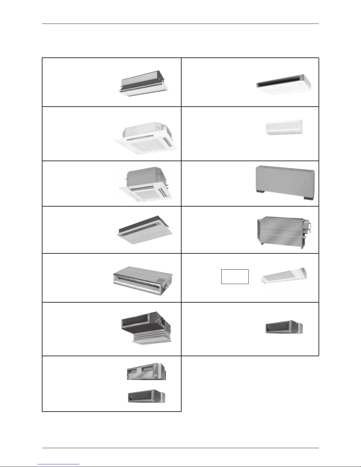
1.2 External Appearance
1.2.1 Indoor Units Heat Pump: 50Hz/60Hz, Cooling Only: 50Hz
Ceiling Mounted Cassette Type (Double Flow)
FXCQ20M
FXCQ25M
FXCQ32M
FXCQ40M
FXCQ50M
FXCQ63M
FXCQ80M
FXCQ125M
Ceiling Suspended Type
FXHQ32MA
FXHQ63MA
FXHQ100MA
Ceiling Mounted Cassette
Type (Multi Flow)
FXFQ25M
FXFQ32M
FXFQ40M
FXFQ50M
FXFQ63M
FXFQ80M
FXFQ100M
FXFQ125M
Wall Mounted Type
FXAQ20MA
FXAQ25MA
FXAQ32MA
FXAQ40MA
FXAQ50MA
FXAQ63MA
600×600 Ceiling Mounted
Cassette Type (Multi Flow)
FXZQ20M
FXZQ25M
FXZQ32M
FXZQ40M
FXZQ50M
Floor Standing Type
FXLQ20MA
FXLQ25MA
FXLQ32MA
FXLQ40MA
FXLQ50MA
FXLQ63MA
Ceiling Mounted Cassette Corner Type
FXKQ25MA
FXKQ32MA
FXKQ40MA
FXKQ63MA
Concealed Floor Standing Type
FXNQ20MA
FXNQ25MA
FXNQ32MA
FXNQ40MA
FXNQ50MA
FXNQ63MA
Slim Ceiling Mounted Duct Type
FXDQ20P FXDQ20N(A)
FXDQ25P FXDQ25N(A)
FXDQ32P FXDQ32N(A)
FXDQ40N(A)
FXDQ50N(A)
FXDQ63N(A)
with Drain Pump (VE)
without Drain Pump (VET)
Ceiling Suspended Cassette Type
(Connection Unit Series)
FXUQ71MA +
FXUQ100MA +
FXUQ125MA +
Connection Unit
Ceiling Mounted Built-In Type
FXSQ20M
FXSQ25M
FXSQ32M
FXSQ40M
FXSQ50M
FXSQ63M
FXSQ80M
FXSQ100M
FXSQ125M
Outdoor air processing
unit
FXMQ125MF
FXMQ200MF
FXMQ250MF
Ceiling Mounted Duct Type
FXMQ40MA
FXMQ50MA
FXMQ63MA
FXMQ80MA
FXMQ100MA
FXMQ125MA
FXMQ200MA
FXMQ250MA
FXMQ40~125M
FXMQ200 · 250M
BEVQ71MA
BEVQ100MA
BEVQ125MA
Product Outline SiEN34-705
4 General Information
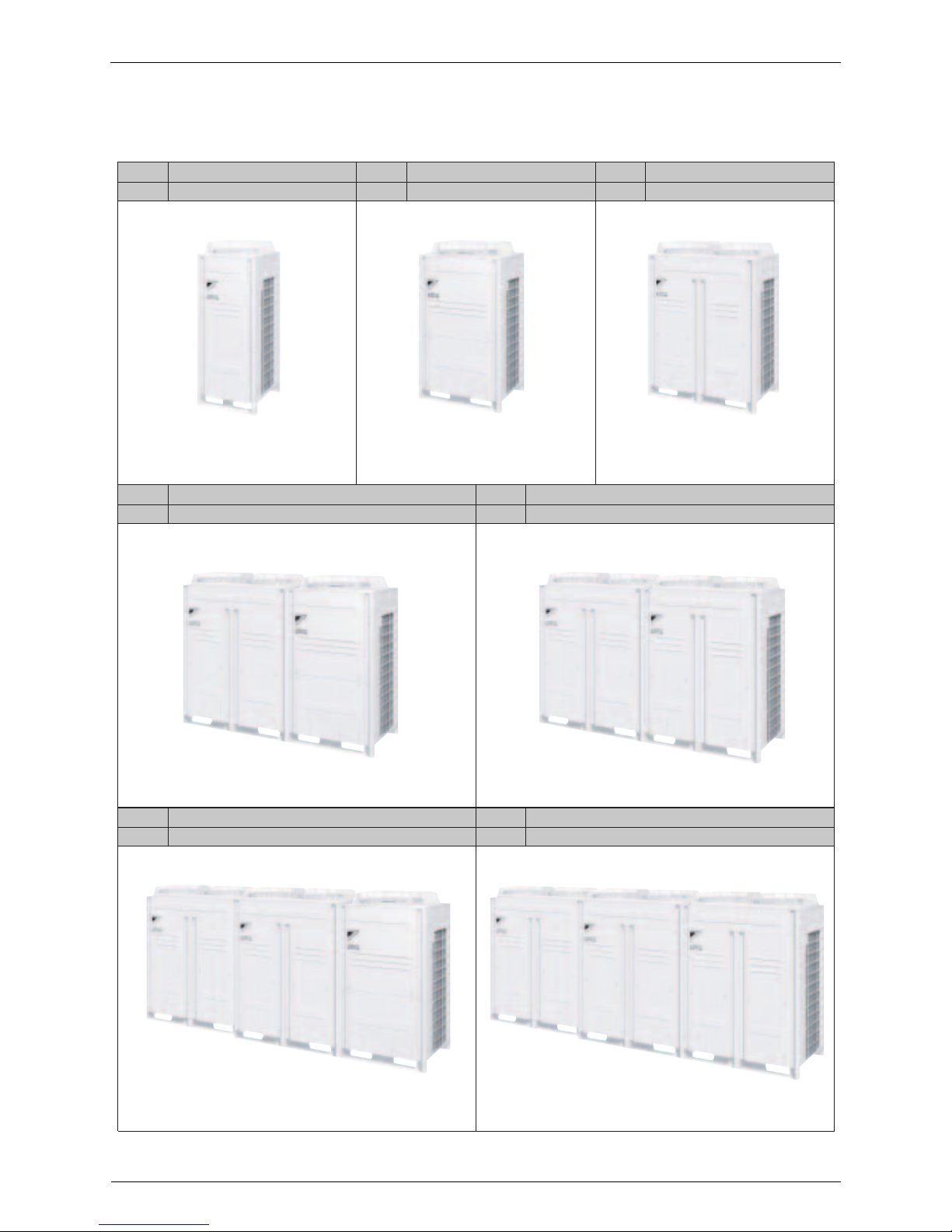
1.2.2 Outdoor Units Heat Pump: 50Hz/60Hz, Cooling Only: 50Hz
Normal Series (Space Saving Series)
RXYQ5P RXYQ8P, 10P (12P: EUROPE)
RXYQ48P, 50P, 52P, 54P
RXYQ12P, 14P, 16P, 18P
5HP 8, 10HP 12, 14, 16, 18HP
20, 22, 24, 26, 28HP 30, 32, 34, 36HP
38, 40, 42, 44, 46HP 48, 50, 52, 54HP
RXYQ5P
RXYQ8P, 10P(12P:EUROPE)
RXYQ12P, 14P, 16P, 18P
RXQ5P
H/P
C/O
H/P
C/O
H/P
C/ORXQ8P, 10P RXQ12P, 14P, 16P,18P
RXYQ5P RXYQ8P, 10P (12P: EUROPE)
H/P
C/O
H/P
C/O
RXYQ20P, 22P, 24P, 26P, 28P
RXQ20P, 22P, 24P, 26P, 28P
RXYQ30P, 32P, 34P, 36P
RXQ30P, 32P, 34P, 36P
RXYQ5P RXYQ8P, 10P (12P: EUROPE)
H/P
C/O
H/P
C/O
RXYQ48P, 50P, 52P, 54P
RXQ48P, 50P, 52P, 54P
RXYQ38P, 40P, 42P, 44P, 46P
RXQ38P, 40P, 42P, 44P, 46P
SiEN34-705 Product Outline
General Information 5
High COP Series (Energy Saving Series)
16, 18HP 24, 26HP
28, 30HP
RXYQ36PH, 38PH, 40PH, 42PH, 44PH, 46PH, 48PH, 50PH
RXQ36PH, 38PH, 40PH, 42PH, 44PH, 46PH, 48PH, 50PH
32, 34HP
36, 38, 40, 42, 44, 46, 48, 50HP
RXYQ5P RXYQ8P, 10P (12P: EUROPE)
RXYQ16PH, 18PH
RXQ16PH, 18PH
RXYQ24PH, 26PH
RXQ24PH, 26PH
RXYQ5P RXYQ8P, 10P (12P: EUROPE)
RXYQ28PH, 30PH
RXQ28PH, 30PH
RXYQ32PH, 34PH
RXQ32PH, 34PH
H/P
C/O
H/P
C/O
H/P
C/O
H/P
C/O
H/P
C/O
Product Outline SiEN34-705
6 General Information
1.3 Combination of Outdoor Units
Normal Series (Space Saving Series)
Note: For multiple connection of 20HP system or more, an optional Daikin Outdoor Unit Multi
Connection Piping Kit is required.
System
Capacity
Number
of units
Module
Outdoor Unit Multi Connection Piping Kit
(Option)
5 8 10 12 14 16 18
5HP 1 l
—
8HP 1 l
10HP 1 l
12HP 1 l
14HP 1 l
16HP 1 l
18HP 1 l
20HP 2 ll
BHFP22P100
22HP 2 ll
24HP 2 ll
26HP 2 ll
28HP 2 ll
30HP 2 ll
32HP 2 ll
34HP 2 ll
36HP 2 ll
38HP 3 ll l
BHFP22P151
40HP 3 lll
42HP 3 lll
44HP 3 lll
46HP 3 lll
48HP 3 lll
50HP 3 lll
52HP 3 lll
54HP 3 lll
SiEN34-705 Product Outline
General Information 7
High COP Series (Energy Saving Series)
Note: For multiple connection of 16HP system or more, an optional Daikin Outdoor Unit Multi
Connection Piping Kit is required.
System
Capacity
Number
of units
Module
Outdoor Unit Multi Connection Piping Kit
(Option)
8 1012141618
16HP 2 ll
BHFP22P100
18HP 2 ll
24HP 3 lll
BHFP22P151
26HP 3 ll l
28HP 3 ll l
30HP 3 lll
32HP 3 lll
34HP 3 lll
36HP 3 lll
38HP 3 ll l
40HP 3 ll l
42HP 3 ll l
44HP 3 lll
46HP 3 lll
48HP 3 lll
50HP 3 ll l
Product Outline SiEN34-705
8 General Information
Connectable Indoor Unit
Note: FXDQ has following 2 Series, as shown below.
FXDQ-P, N(A)VET: without Drain Pump
(
For General, Asia: except for EU, China and Australia
)
FXDQ-P, N(A)VE : with Drain Pump
FXZQ : only for EU, Australia
Indoor unit capacity
Use the above tables to determine the capacities of indoor units to be connected. Make sure the
total capacity of indoor units connected to each outdoor unit is within the specified value (kW).
! The total capacity of connected indoor units must be within a range of 50 to 130% of the
rated capacity of the outdoor unit.
! In some models, it is not possible to connect the maximum number of connectable indoor
units. Select models so the total capacity of connected indoor units conforms to the
specification.
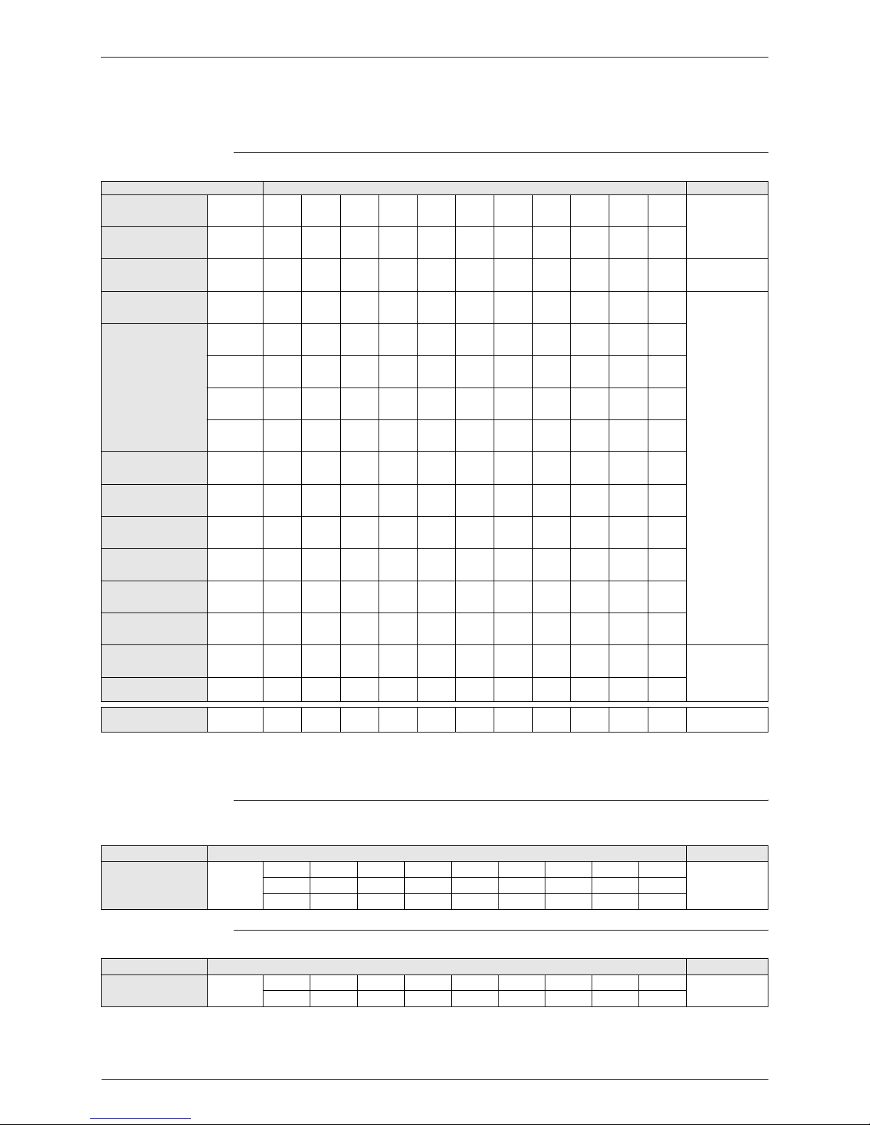
Type Model Name Power Supply
Ceiling Mounted
Cassette Type
(Double Flow)
FXCQ 20M 25M 32M 40M 50M 63M 80M — 125M — —
VE
Ceiling Mounted
Cassette Type
(Multi Flow)
FXFQ — 25M 32M 40M 50M 63M 80M 100M 125M — —
600×600 Ceiling
Mounted Cassette
Type (Multi Flow)
FXZQ 20M 25M 32M 40M 50M — — — — — — V1
Ceiling Mounted
Cassette Corner Type
FXKQ — 25MA 32MA 40MA — 63MA — — — — —
VE
Slim Ceiling Mounted
Duct Type
FXDQPVE
20P 25P 32P — — — — — — — —
FXDQPVET
20P 25P 32P — — — — — — — —
FXDQNAVE
20NA 25NA 32NA 40NA 50NA 63NA — — — — —
FXDQNVET
20N 25N 32N 40N 50N 63N — — — — —
Ceiling Mounted
Built-In Type
FXSQ 20M 25M 32M 40M 50M 63M 80M 100M 125M — —
Ceiling Mounted
Duct Type
FXMQ — — — 40MA 50MA 63MA 80MA
100MA 125MA 200MA 250MA
Ceiling Suspended
Type
FXHQ — — 32MA — — 63MA —
100MA
———
Wall Mounted Type
FXAQ 20MA 25MA 32MA 40MA 50MA 63MA — — — — —
Floor Standing Type
FXLQ 20MA 25MA 32MA 40MA 50MA 63MA — — — — —
Concealed Floor
Standing Type
FXNQ 20MA 25MA 32MA 40MA 50MA 63MA — — — — —
New refrigerant model code P20
type
P25
type
P32
type
P40
type
P50
type
P63
type
P80
type
P100
type
P125
type
P200
type
P250
type
Selecting model capacity 2.2
kW
2.8
kW
3.5
kW
4.5
kW
5.6
kW
7.0
kW
9.0kW11.2kW14.0kW22.4kW28.0
kW
Equivalent output 0.8HP 1HP
1.25HP
1.6HP 2.0HP 2.5HP 3.2HP 4HP 5HP 8HP 10HP

SiEN34-705 Product Outline
General Information 9
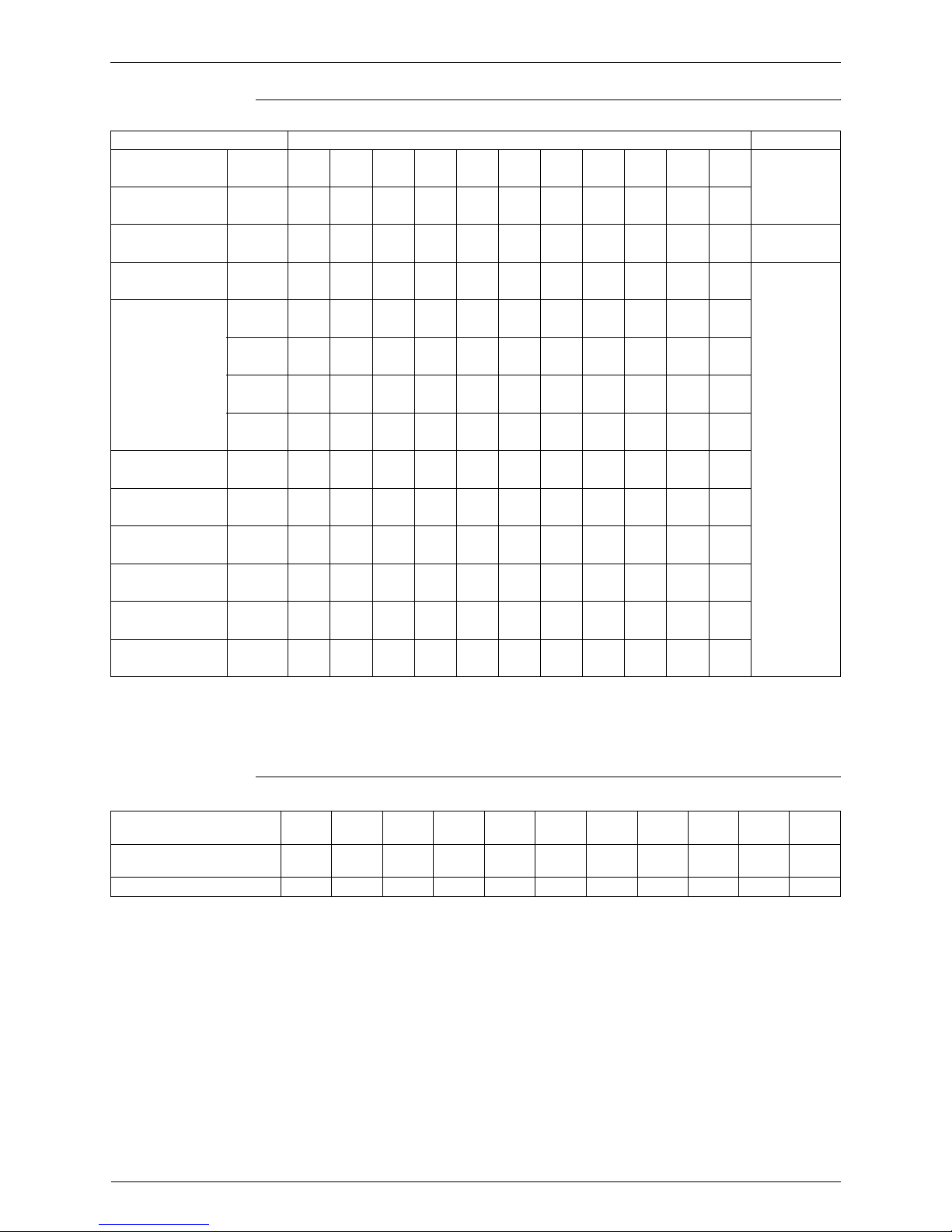
Differences from Conventional Models
Item
Differences
Object New model (P Model) Conventional model (MA Model)
Compressor Connection of equalizer oil pipe
" NONE
(No particular changes in
terms of service)
" YES
Workability
Equalizer oil pipe for multioutdoor-unit system
" NONE " YES
Procedure for calculating
refrigerant refilling quantity
" Refilling quantity due to piping
length + Adjustment quantity
according to models of
outdoor units
" Refilling quantity due to piping
length - Adjustment quantity
according to models of
outdoor units
Optional accessories
Branch pipe for outdoor unit
connection
" Y branch
Type: BHFP22P100/151
" T branch
Type: BHFP22MA90/135
Product Outline SiEN34-705
10 General Information
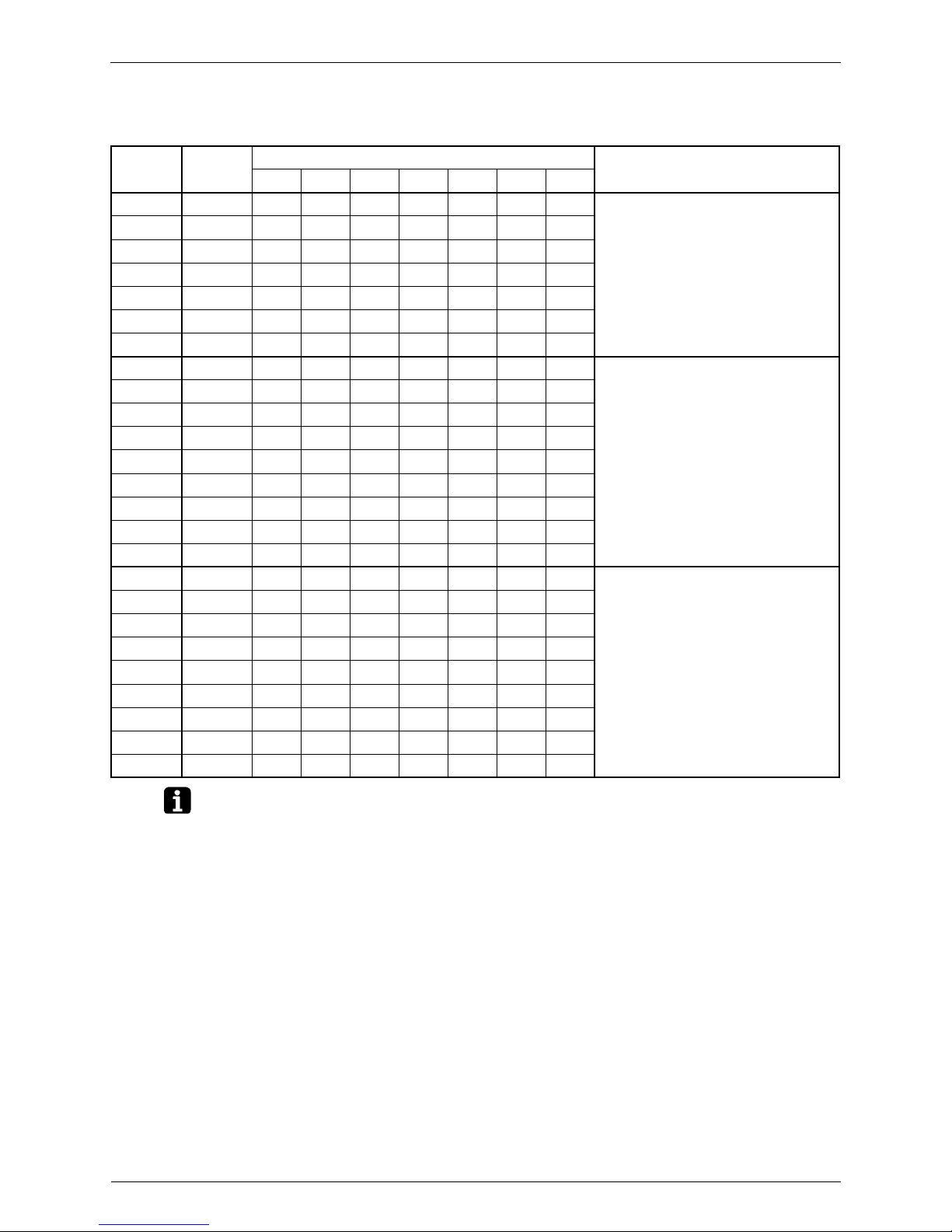
1.4 Model Selection
VRV III Heat Pump: 50Hz/60Hz, Cooling Only: 50Hz
Connectable indoor units number and capacity
Normal Series
HP 5HP 8HP 10HP 12HP 14HP 16HP 18HP
System name RX(Y)Q5P RX(Y)Q8P RX(Y)Q10P RX(YQ12P RX(YQ14P RX(YQ16P RX(YQ18P
Outdoor unit 1 RX(Y)Q5P RX(Y)Q8P RX(Y)Q10P RX(Y)Q12P RX(Y)Q14P RX(Y)Q16P RX(Y)Q18P
Outdoor unit 2 – – – – – – –
Outdoor unit 3 – – – – – – –
Total number of connectable
indoor units
8 131619232629
Total capacity of connectable
indoor units (kW)
7.00~18.20 11.20~29.12 14.00~36.40 16.75~43.55 20.00~52.00 22.40~58.24 25.20~65.52
HP 20HP 22HP 24HP 26HP 28HP 30HP 32HP
System name RX(Y)Q20P RX(Y)Q22P RX(Y)Q24P RX(Y)Q26P RX(Y)Q28P RX(Y)Q30P RX(Y)Q32P
Outdoor unit 1 RX(Y)Q8P RX(Y)Q10P RX(Y)Q8P RX(Y)Q8P RX(Y)Q10P RX(Y)Q12P RX(Y)Q16P
Outdoor unit 2 RX(Y)Q12P RX(Y)Q12P RX(Y)Q16P RX(Y)Q18P RX(Y)Q18P RX(Y)Q18P RX(Y)Q16P
Outdoor unit 3 – – – – – – –
Total number of connectable
indoor units
32 35 39 42 45 48 52
Total capacity of connectable
indoor units (kW)
27.95~72.67 30.75~79.95 33.60~87.36 36.40~94.64 39.15~101.79 41.95~109.07 44.70~116.22
HP 34HP 36HP 38HP 40HP 42HP 44HP 46HP
System name RX(Y)Q34P RX(Y)Q36P RX(Y)Q38P RX(Y)Q40P RX(Y)Q42P RX(Y)Q44P RX(Y)Q46P
Outdoor unit 1 RX(Y)Q16P RX(Y)Q18P RX(Y)Q8P RX(Y)Q8P RX(Y)Q8P RX(Y)Q8P RX(Y)Q10P
Outdoor unit 2 RX(Y)Q18P RX(Y)Q18P RX(Y)Q12P RX(Y)Q16P RX(Y)Q16P RX(Y)Q18P RX(Y)Q18P
Outdoor unit 3 – – RX(Y)Q18P RX(Y)Q16P RX(Y)Q18P RX(Y)Q18P RX(Y)Q18P
Total number of connectable
indoor units
55 58 61 64
Total capacity of connectable
indoor units (kW)
47.50~123.50 50.25~130.65 53.50~139.10 56.00~145.60 58.00~150.80 61.75~160.55 63.75~165.75
HP 48HP 50HP 52HP 54HP
System name RX(Y)Q48P RX(Y)Q50P RX(Y)Q52P RX(Y)Q54P
Outdoor unit 1 RX(Y)Q12P RX(Y)Q14P RX(Y)Q16P RX(Y)Q18P
Outdoor unit 2 RX(Y)Q18P RX(Y)Q18P RX(Y)Q18P RX(Y)Q18P
Outdoor unit 3 RX(Y)Q18P RX(Y)Q18P RX(Y)Q18P RX(Y)Q18P
Total number of connectable
indoor units
64
Total capacity of connectable
indoor units (kW)
67.50~175.50 69.50~180.70 71.50~185.90 73.50~191.10
SiEN34-705 Product Outline
General Information 11
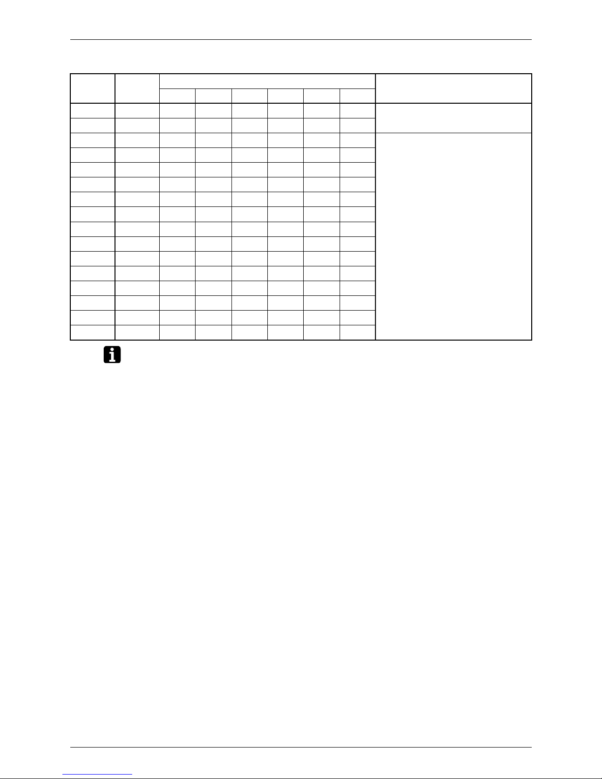
High COP Series (Energy Saving Series)
HP 16HP 18HP
System name RX(Y)Q16PH RX(Y)Q18PH
Outdoor unit 1 RX(Y)Q8P RX(Y)Q8P
Outdoor unit 2 RX(Y)Q8P RX(Y)Q10P
Outdoor unit 3 – –
Total number of connectable
indoor units
26 29
Total capacity of connectable
indoor units (kW)
22.40~58.24 25.20~65.52
HP 24HP 26HP 28HP 30HP 32HP
System name RX(Y)Q24PH RX(Y)Q26PH RX(Y)Q28PH RX(Y)Q30PH RX(Y)Q32PH
Outdoor unit 1 RX(Y)Q8P RX(Y)Q8P RX(Y)Q8P RX(Y)Q8P RX(Y)Q8P
Outdoor unit 2 RX(Y)Q8P RX(Y)Q8P RX(Y)Q8P RX(Y)Q10P RX(Y)Q12P
Outdoor unit 3 RX(Y)Q8P RX(Y)Q10P RX(Y)Q12P RX(Y)Q12P RX(Y)Q12P
Total number of connectable
indoor units
39 42 45 48 52
Total capacity of connectable
indoor units (kW)
33.60~87.36 36.40~94.64 39.15~101.79 41.95~109.07 44.70~116.22
HP 34HP 36HP 38HP 40HP 42HP 44HP 46HP
System name RX(Y)Q34PH RX(Y)Q36PH RX(Y)Q38PH RX(Y)Q40PH RX(Y)Q42PH RX(Y)Q44PH RX(Y)Q46PH
Outdoor unit 1 RX(Y)Q10P RX(Y)Q12P RX(Y)Q12P RX(Y)Q12P RX(Y)Q12P RX(Y)Q12P RX(Y)Q12P
Outdoor unit 2 RX(Y)Q12P RX(Y)Q12P RX(Y)Q12P RX(Y)Q12P RX(Y)Q12P RX(Y)Q16P RX(Y)Q16P
Outdoor unit 3 RX(Y)Q12P RX(Y)Q12P RX(Y)Q14P RX(Y)Q16P RX(Y)Q18P RX(Y)Q16P RX(Y)Q18P
Total number of connectable
indoor units
55 58 61 64
Total capacity of connectable
indoor units (kW)
47.50~123.50 50.25~130.65 53.50~139.10 56.00~145.60 58.00~150.80 61.75~160.55 63.75~165.75
HP 48HP 50HP
System name RX(Y)Q48PH RX(Y)Q50PH
Outdoor unit 1 RX(Y)Q16P RX(Y)Q16P
Outdoor unit 2 RX(Y)Q16P RX(Y)Q16P
Outdoor unit 3 RX(Y)Q16P RX(Y)Q18P
Total number of connectable
indoor units
64
Total capacity of connectable
indoor units (kW)
67.50~175.50 69.50~180.70
Points to Bear in Mind at the System Design SiEN34-705
12 General Information
2. Points to Bear in Mind at the System Design
2.1 Points Relating to the Performance of the Air
Conditioning Units
A number of points need to be borne in mind at the system design stage in order to ensure the
mechanical efficiency of the air conditioning units.
1. Path of refrigerant piping between outdoor and indoor units, height difference and
pipe length.
! Path of refrigerant piping should be determined such that length of piping is kept to a
minimum.
! Piping should be kept within permissible limits in terms of length and height difference.
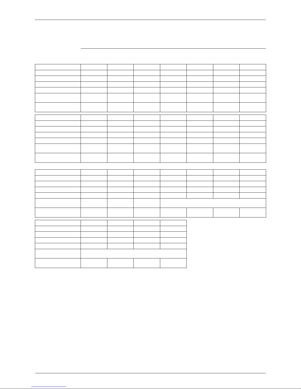
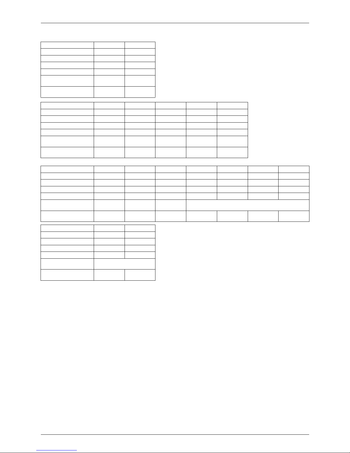
2. Positioning of outdoor unit
! Position such that maintenance and repairs can be carried out. (leave room for servicing)
! Avoid reduction of airflow and short circuiting
! Avoid reduction of airflow and short circuiting
Front
Inlet
SiEN34-705 Points to Bear in Mind at the System Design
General Information 13
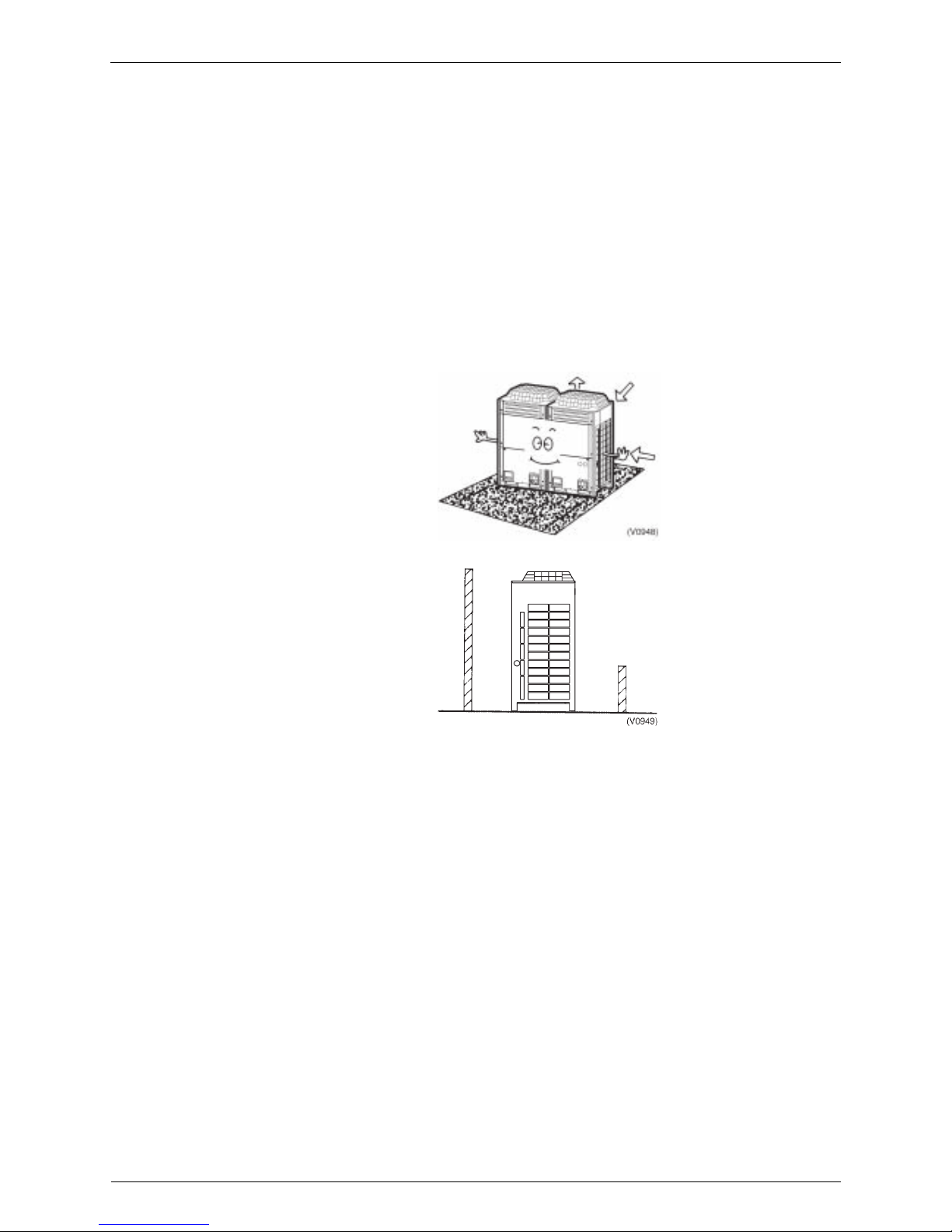
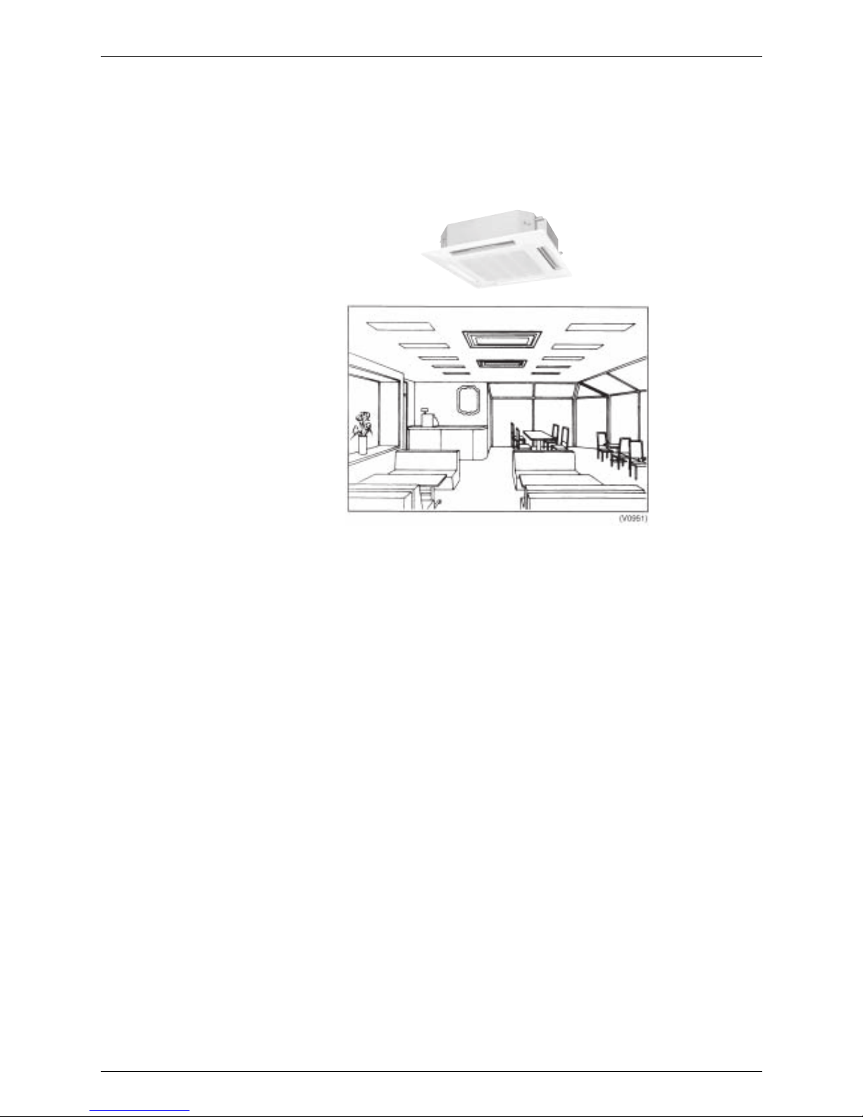
3. Positioning of indoor unit
! Position such that maintenance and repairs can be carried out. (inspection port positions
and size check)
! Avoid short circuiting
! Ensure sufficient drain pipe gradient (need for drain-up kit etc.)
! In the case of a ceiling mounted type make sure ceiling depth is sufficient (need for high
performance filter, etc.)
Points to Bear in Mind at the System Design SiEN34-705
14 General Information
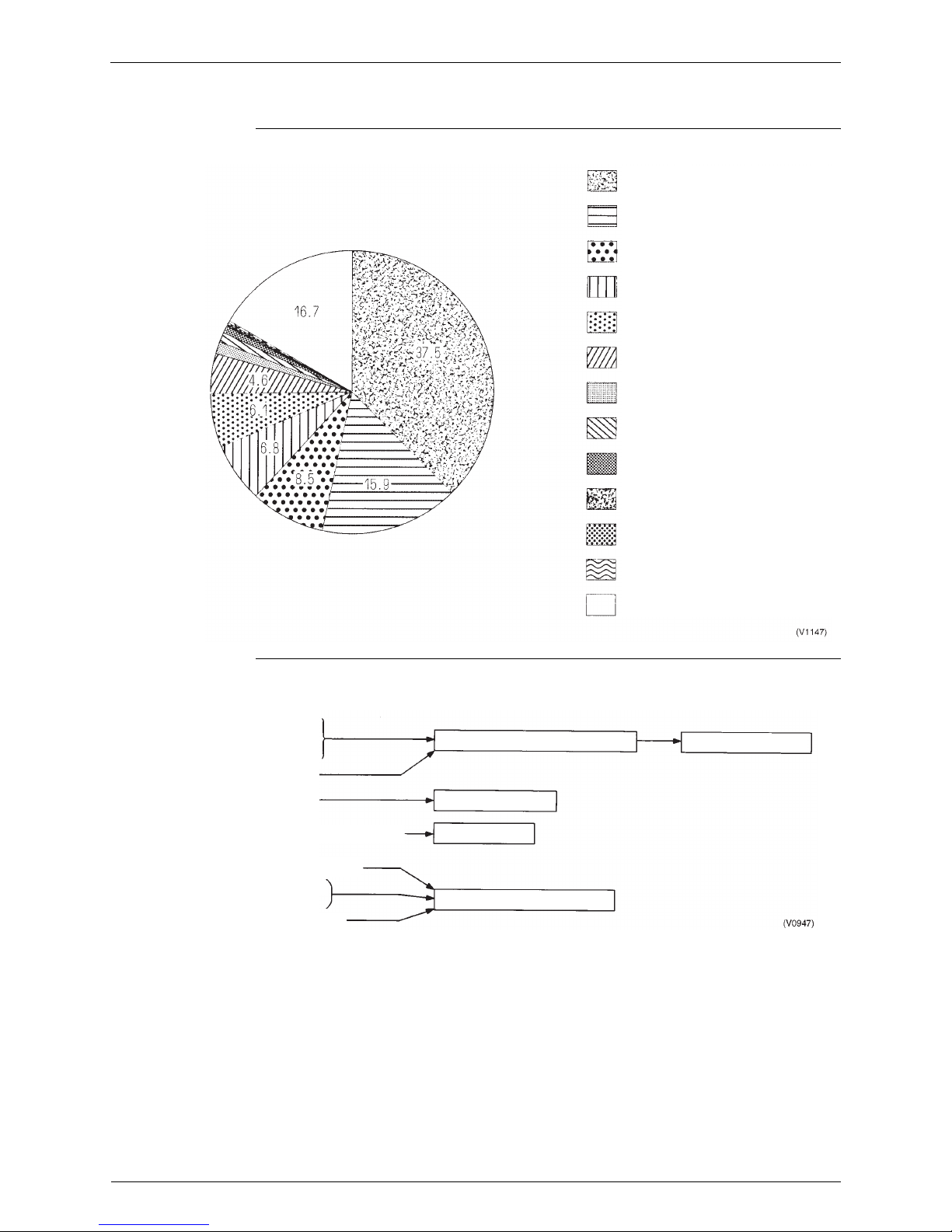
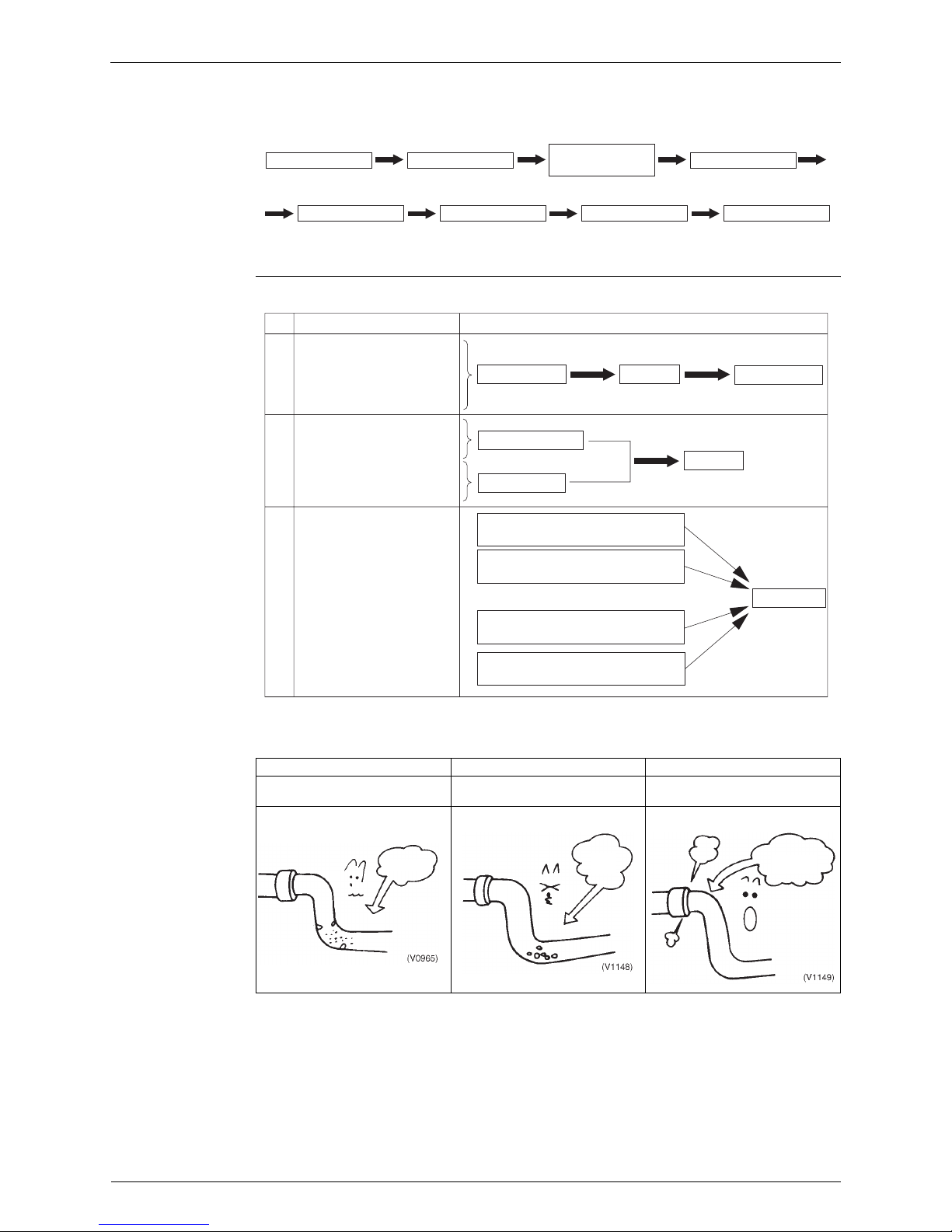
2.2 The Installation is of Vital Importance
The analysis of major installation problems experienced is shown below;
How these installation problems affect an equipment are shown below:
Wrong interconnection wiring
Wrong setting of switches
Wrong power line wiring
Improper field piping
Improper drain piping
Refrigerant leak from FLARE
Improper model selection
Refrigerant leak from BRAZING
Improper installation place
Improper power supply voltage
Defective insulation work
Improper technical information
Miscellaneous
37.5%
15.9%
8.5%
6.8%
6.1%
4.8%
1.4%
1.1%
0.9%
0.3%
0.2%
0.2%
16.9%
Refrigerant leak from tubes
Shortage of refrigerant
Piping and wiring upsidedown
Contamination inside tubes
Moisture inside tubes
Improper installation place (short circuit of air
Powerline connected to control circuit
Insulation test applied to circuits
orther than power line
Excessive force applied to PC board
Operation under over heat condition
Oil return insufficient
Reduced capacity
Defective electronic component
Defective compressor
SiEN34-705 Points to Bear in Mind at the System Design
General Information 15
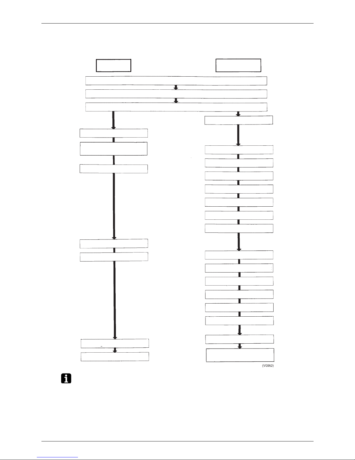
2.3 Striking a Balance between System Installation and
General Construction Work (Comprehensive Flow Chart)
Note: 1. The division of the work should be thoroughly clarified. (This applies particularly to work
relating to the connection of control wiring, fitting of remote control and central control panel,
boundary work on areas such as connection of drain piping and humidification supply piping,
inspection and foundation)
2. Keep a constant check on the progress of the construction work to avoid deviations from the
air conditioning work schedule.
3. For sleeve and insert work the positions of ceiling girders should be confirmed and sleeve
and insert requirement, hole diameters, positioning and numbers decided. This is particularly
important in the case of sleeves for drain piping.
Construction
work
Air conditioning
work
Determination of division of work
Settling operational details
Settling sleeve and insert work details
Fitting of steel sleeves
Molding box and
reinforcement work
Removal of molding boxes
Ceiling preparations
Building rooftop cinder concrete
Preparation of contract drawings
Sleeve and insert work
Installation of indoor unit
Refrigerant piping work
Drain pipe work
Duct work
Heat insulation work
Electrical work
Installation of outdoor unit
Air tight test
Vacuum drying
Fit decoration panels
Te s t r u n
Transfer to customer with
explanation
Additional charge of refrigerant
Outdoor unit foundation work
Energization
Cleaning inside and outside
Points to Bear in Mind at the System Design SiEN34-705
16 General Information
2.4 Points to Bear in Mind when Preparing the Contract
Drawings
The following points should be borne in mind when preparing the contract drawings from the
original drawings and the execution drawings.
The contract drawings for the air conditioning system are blueprints for the performance of the
necessary work which are drawn up on the basis of the original drawings in such a way that a
working balance is achieved between the specific requirements of each individual aspect of the
work.
Contract Drawing Objectives include:
! The drawings should be easily comprehensible to those carrying out the work.
! The contents of the drawings should not be subject to subsequent alteration.
The following is a list of the main points to be considered when preparing contract drawings for
the III System and should be used as a reference during this stage of the work:
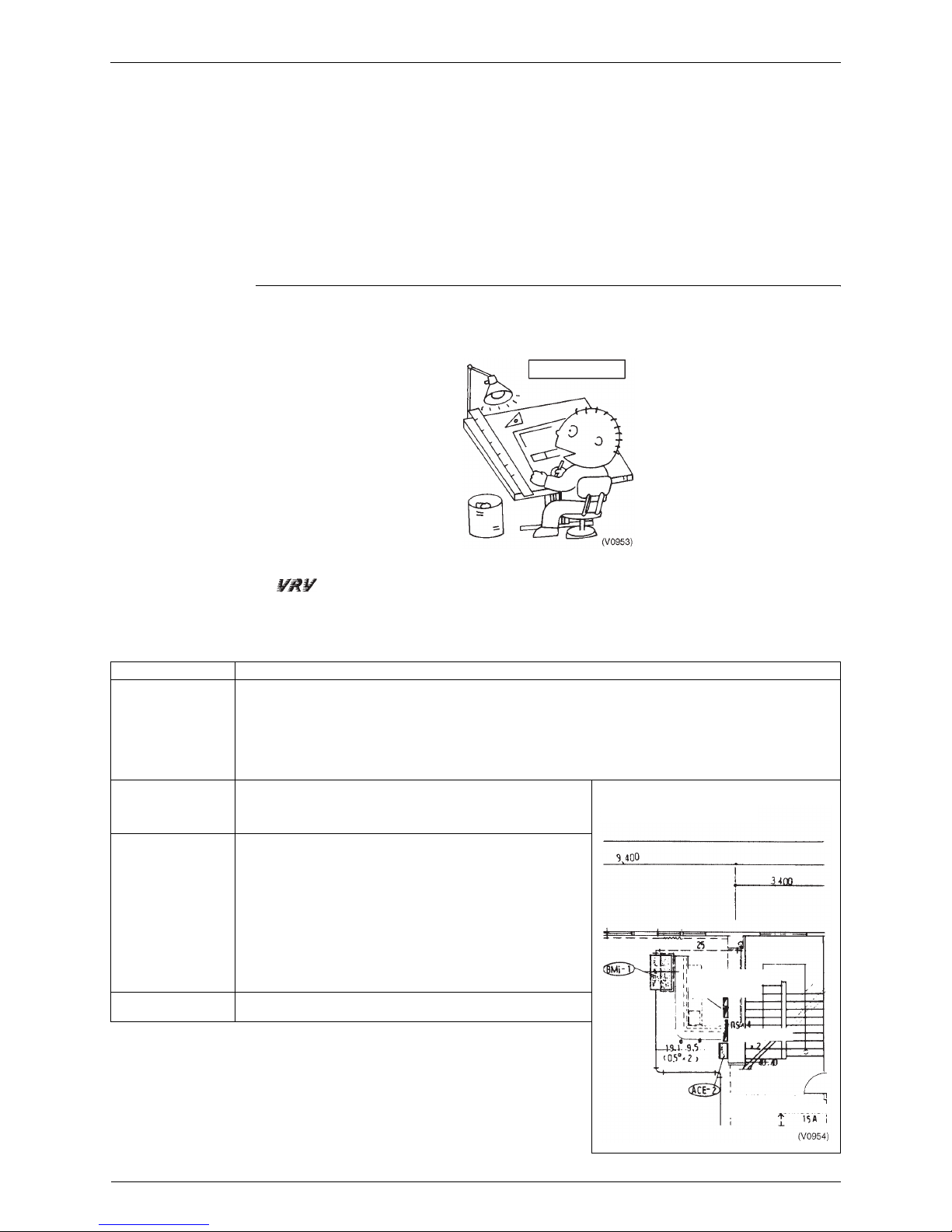
2.4.1 At the Contract Drawing Stage the Following Points are Critical!!
Contract drawing
Check points
Arrangement of units 1. Have you left the access passages clear and allowed sufficient room for servicing?
2. Have you taken full account of the possibility of short circuits? (Both indoor and outdoor units)
3. Can the air filters be replaced easily?
4. Have you indicated the size and location of the ceiling inspection ports? (Make sure there no other installations in
the area above)
5. Have you taken into account the depth of the installation area? (In case of ceiling built-in type)
6. Have you specified the position of the indoor unit clearly? (Have you taken full account of relevant features of the
local ventilation, humidity and lighting?)
Refrigerant piping 1. Is the piping system correctly connected?
2. Are the rise and fall pipes correctly connected?
3. Are the lengths and height differences of the pipes within the
recommended limits?
Operational control 1. Are the interconnections between the piping and wiring of the
indoor and outdoor units clearly shown?
2. Are the numbers of the local setting switches clearly shown?
(Group No. and Unit No.)
3. Are the wiring connections between the remote control and the
centralized and remote controls clearly shown?
Refer to the notes relating to the preparation of the control
wiring system diagrams (see next page)
4. Are the different types of wires clearly marked?
5. Are the any problems with the way the power supply cables and
control wiring have been separated or bound together?
6. Are the inter-floor connections of the control wiring correct?
7. Is the position of the remote control clearly marked?
Miscellaneous 1. Have you checked the gradient of the drain piping? (Must be at
least 1/100)
(Example of a contract drawing)
Heat adjuster
Heating/cooling
selector switch
Humidifying water
supply pipe connection
SiEN34-705 Points to Bear in Mind at the System Design
General Information 17
2.4.2 Main Considerations in Preparation of Control Circuit Diagrams
In addition to the design of the appropriate this system configuration it is also essential that the
control system be made amply clear. If the system is designed and installed without a clear,
comprehensive plan then problems are inevitably going to occur during the test run.
Servicing too will become much more time consuming than necessary. However, if control
circuit diagrams are prepared along with the contract drawings in order to make the total system
clearly visible then the essential points relating to the electrical connections will be easily
understood, the test run will go off without a hitch and the whole system will be rendered fully
effective.
Step 1: Compiling
a System List
1. Mark each outdoor unit with a code.
2. Add field settings and data for outdoor units, and outdoor unit No. if using sequential start.
3. Add the model number of each indoor unit connected to each refrigerant circuit.
4. Assign each indoor unit a code.
5. Fill in the location of each indoor unit.
6. Group indoor units controlled by one or two remote controls. (group or individual control).
7. Assign central group Nos. if using centralized control.
8. Add field settings and optional equipment for indoor units.
9. Add unit No. if making separate field settings for each indoor unit under group control.
Note: With the VRV III R-410A Heat Pump, Cooling Only Series, unit No. is determined through
automatic addressing, therefore readout unit Nos. after activating the power.
For details on field settings and centralized control group No., refer to the installation manual
and system reference materials.
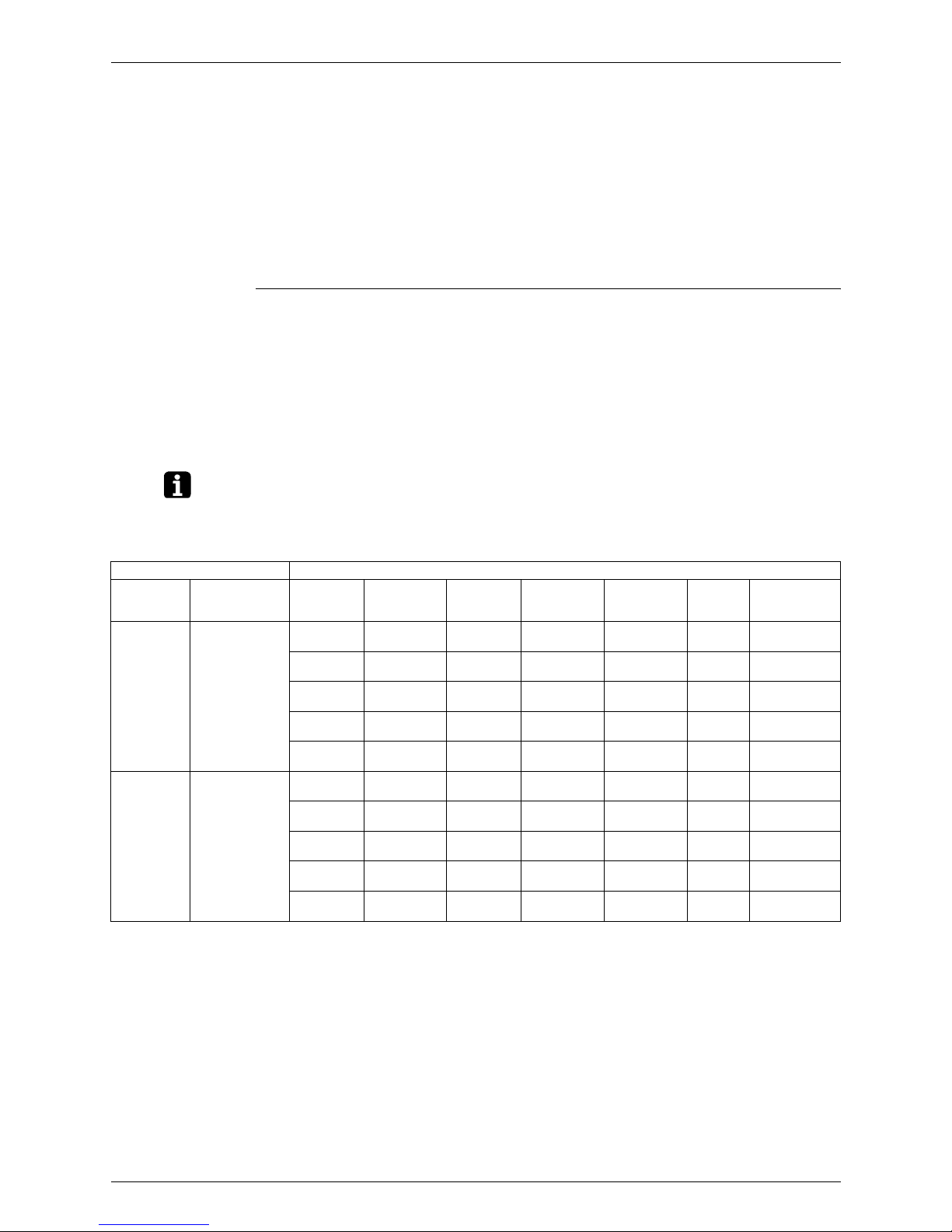
Example: System list
Outdoor Unit Indoor Unit
Model Name
(code)
Field Settings Model Name System Name Location
Remote
Control Group
Centralized
Control Group
No.
Unit No.
Optional
equipment, field
settings, etc.
RX(Y)Q16P
(PAC1)
Cool/Heat
selector:
Indoor unit
Low noise
operation
(L.N.O.P):
Individual control
Sequential start:
ON Defrost:
Earlier
Sequential start
No.
FXCQ32M 2F01
2nd floor
office
A 1–00
FXSQ63M 2F02
2nd floor
office
A (1–00)
FXCQ40M 2F03
2nd floor
office
A (1–00)
FXHQ63MA 2F04
2nd floor
office
B 1–01
FXCQ50M 2F05
2nd floor
office
B (1–01)
RX(Y)Q18P
(PAC2)
Cool/Heat
selector:
Indoor unit
Low noise
operation
(L.N.O.P):
Individual control
Sequential start:
ON Defrost:
Earlier
FXSQ32M 3F01
3rd floor
office
C 1–02
FXCQ40M 3F02
3rd floor
office
C (1–02)
FXSQ40M 3F03
3nd floor
office
C (1–02)
FXCQ50M 3F04
3rd floor
office
D 1–03
Points to Bear in Mind at the System Design SiEN34-705
18 General Information
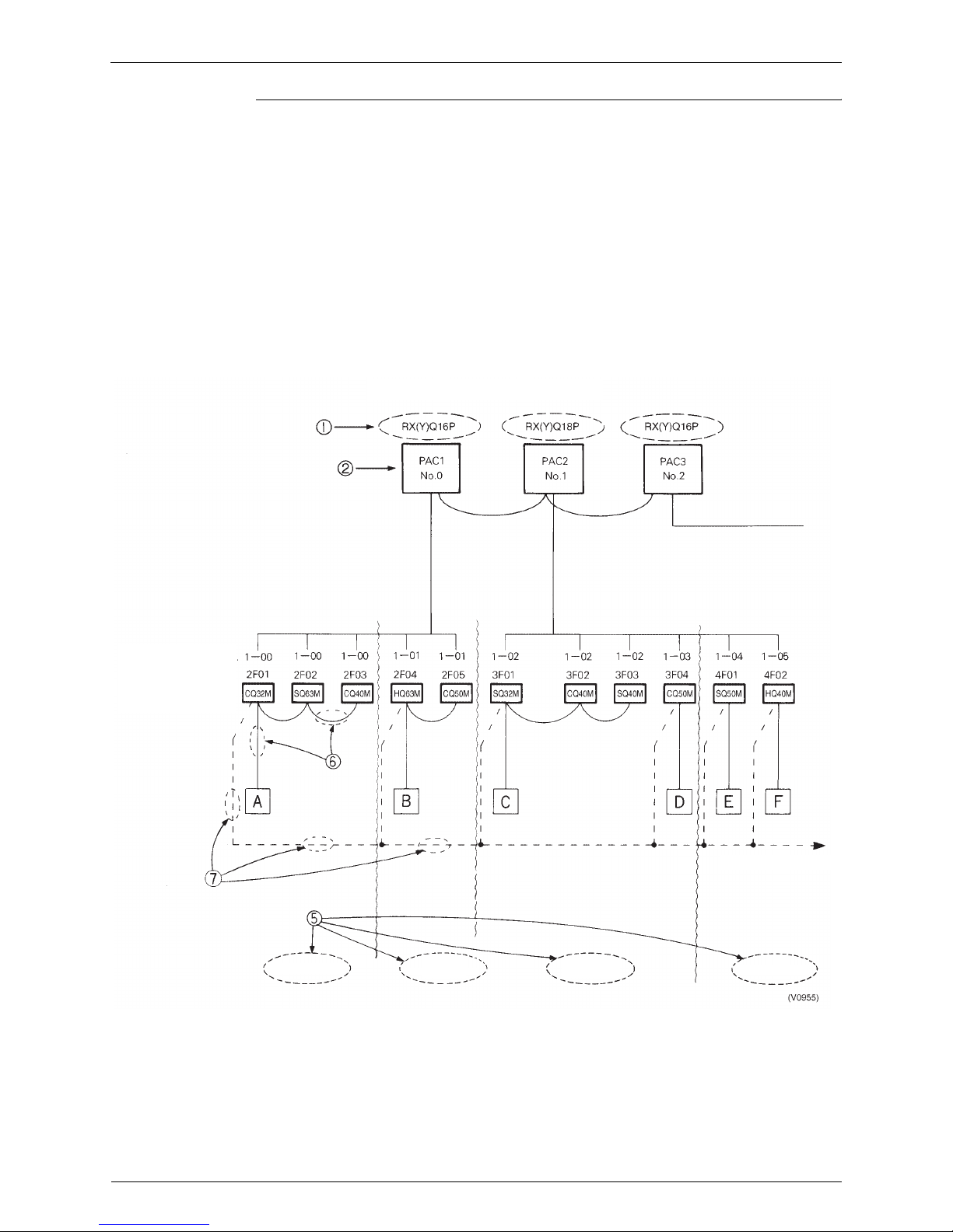
Step 2:
Preparation of the
Control Circuit
Diagrams
The following sequence should be followed in order to prepare control circuit diagrams in
accordance with the system list which has already been completed:
1 Diagrams should be prepared for each individual outdoor unit. The outdoor unit model
number should be inserted into the diagram. (RX(Y)Q16P)
2 Insert name of refrigerant system. (PAC1, PAC2)
3 Insert name of indoor unit. (FXCQ32M→CQ32M)
4 Insert system name of indoor unit.
5 Insert installation position. (Do this when demarcation is possible)
6 Insert remote control control wiring. (Group) Indicated by solid line. ........Solid line.
7 Insert centralized control wiring. ........Dotted line
8 Insert Group No. (G No. for each indoor unit with U No. 0)
The control circuit diagrams are now complete.
Example: Control circuit diagram
Example: Control circuit diagram
Centralized group No
쩻 System name
쩺 Model name
2nd floor office
2nd floor
reception room
3rd floor
design room
4th floor office
To central control panel
SiEN34-705 Installation
General Information 19
3. Installation
3.1 Step by Step Installation Procedure
The above list indicates the order in which the individual work operations are normally carried
out but this order may be varied where local conditions warrant such a change
Determination of division of work
Preparation of contract drawings
Sleeve and insert work
Installation of indoor unit
Refrigerant piping work
Drain pipe work
Duct work
Heat insulation work
Prework
Work
< Operations >
< Points>
Indicate clearly who is to be responsible for switch
settings.
Make relationship between outdoor, indoor, remote
control and option connections clear. (Prepare control
diagrams).
Take account of gradient of drain piping.
Check model name to make sure the fitting is made
correctly.
Special attention to dryness, cleanness and tightness.
Adjust to downward gradient.
Make sure airflow is sufficient.
Make sure no gaps are left where the insulating
materials are joined.
Multiple core cable must not be used. (Suitable cable
should be selected).
Must be carried out in strict accordance with control
circuit diagrams.
The foundation must be level.
Avoid short circuits and ensure sufficient space is
allowed for servicing.
Must be carried out in strict accordance with control
circuit diagrams
(Sequence start, low noise input, Cooling/Heating
selection refrigerant piping lenght etc.).
In the final check for 24 hours at 3.80 MPa there must
be no drop in pressure.
The vacuum pump used must have a capacity of
reaching at least 5mmHg
The amount of refrigerant to be added to the unit should
be calculated and written on th “Added Refrigerant” plate
and attached to the rear side of the front cover.
Make sure there are no gaps left between the decoration
panel and ceiling
Run each indoor unit in turn to make sure the pipework
has been fitted correctly
Explain the use of the system as clearly as possible to
your customer and make sure all relevant documentation
Electrical work (connection circuits
and drive circuits)
Setting of indoor unit setting
switches
Outdoor unit foundation work
Installation of outdoor unit
Setting of outdoor unit setting
switch
Air tight test
Vacuum drying
Additional charge of refrigerant
Fit decoration panels
Test run adjustment
Transfer to customer with explanation
Installation SiEN34-705
20 General Information
3.2 Work Involved in Individual Operations and Points to be
Borne in Mind
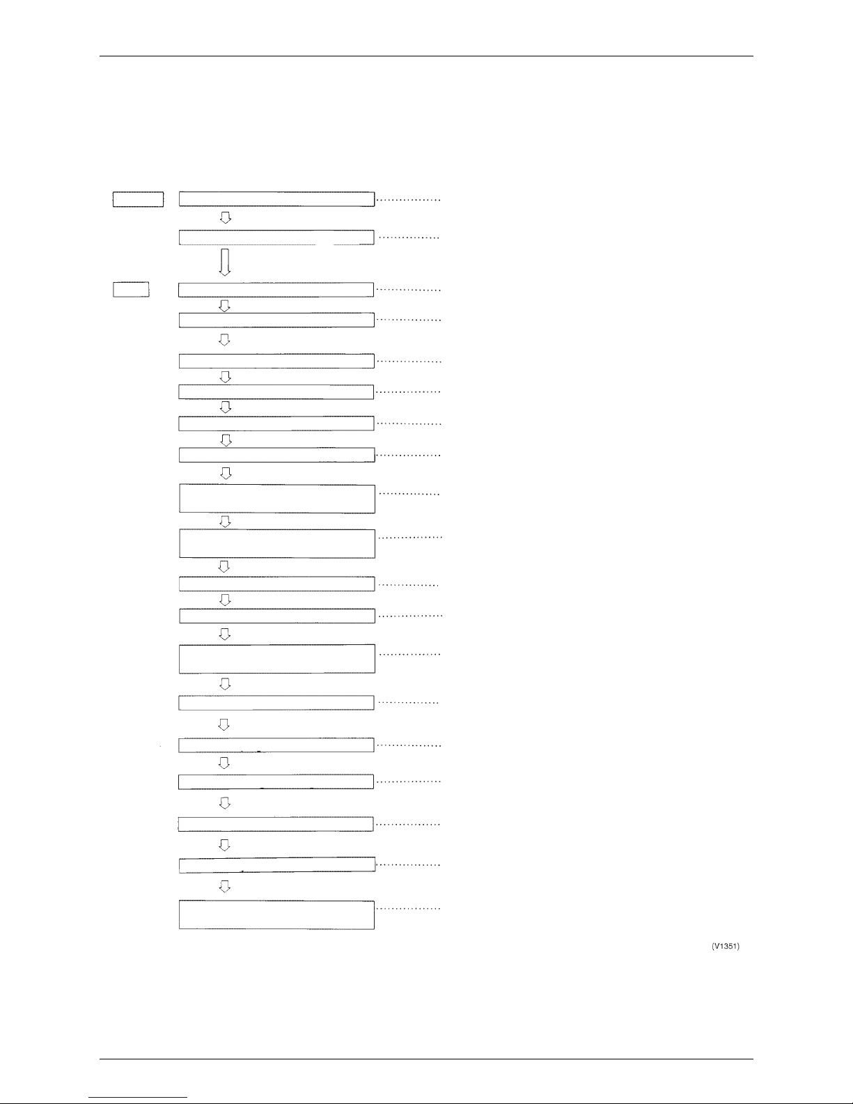
3.2.1 Sleeve and Insert Work
! Operational steps
Positioning of the
Pipe Holes
a) The through holes for the drain piping should be positioned such that the pipes have a
downward gradient. (The gradient must be at least 1/100. The thickness of the insulating
materials must also be taken into consideration.)
b) The diameter of the through holes for the refrigerant piping should include an allowance for
the thickness of the heat insulation materials. (It is a good idea to think of the liquid and gas
pipes as pairs.)
c) Attention should be paid to the construction of the beam themselves since there are
sometimes parts of the beam which cannot be used to accommodate through holes.
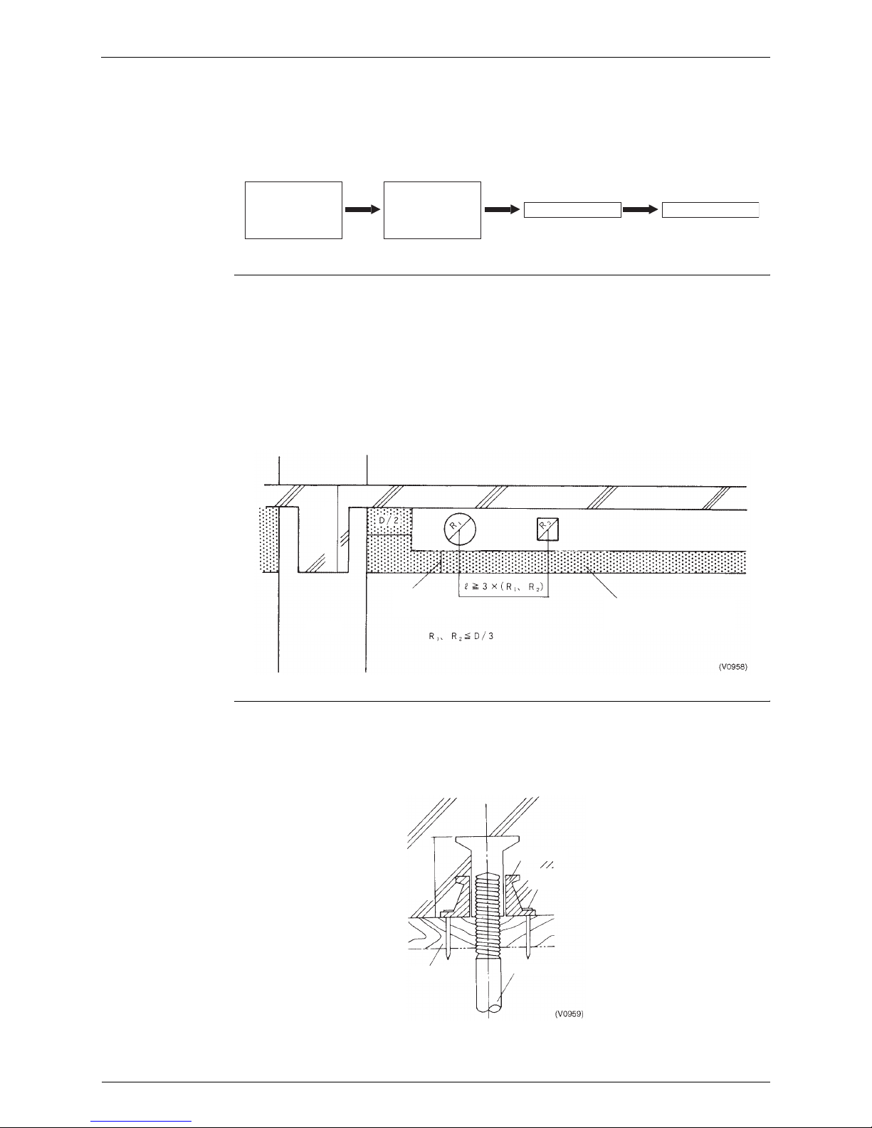
Example: Through holes in a reinforced concrete beam
Positioning the
Insert
a) An insert is a metal tool which is inserted into a floor or a beam before the concrete is set
such that fittings such as ducts, pipes or suspension bolts for hanging units can be fitted into
place later. The positions of the inserts must be decided early.
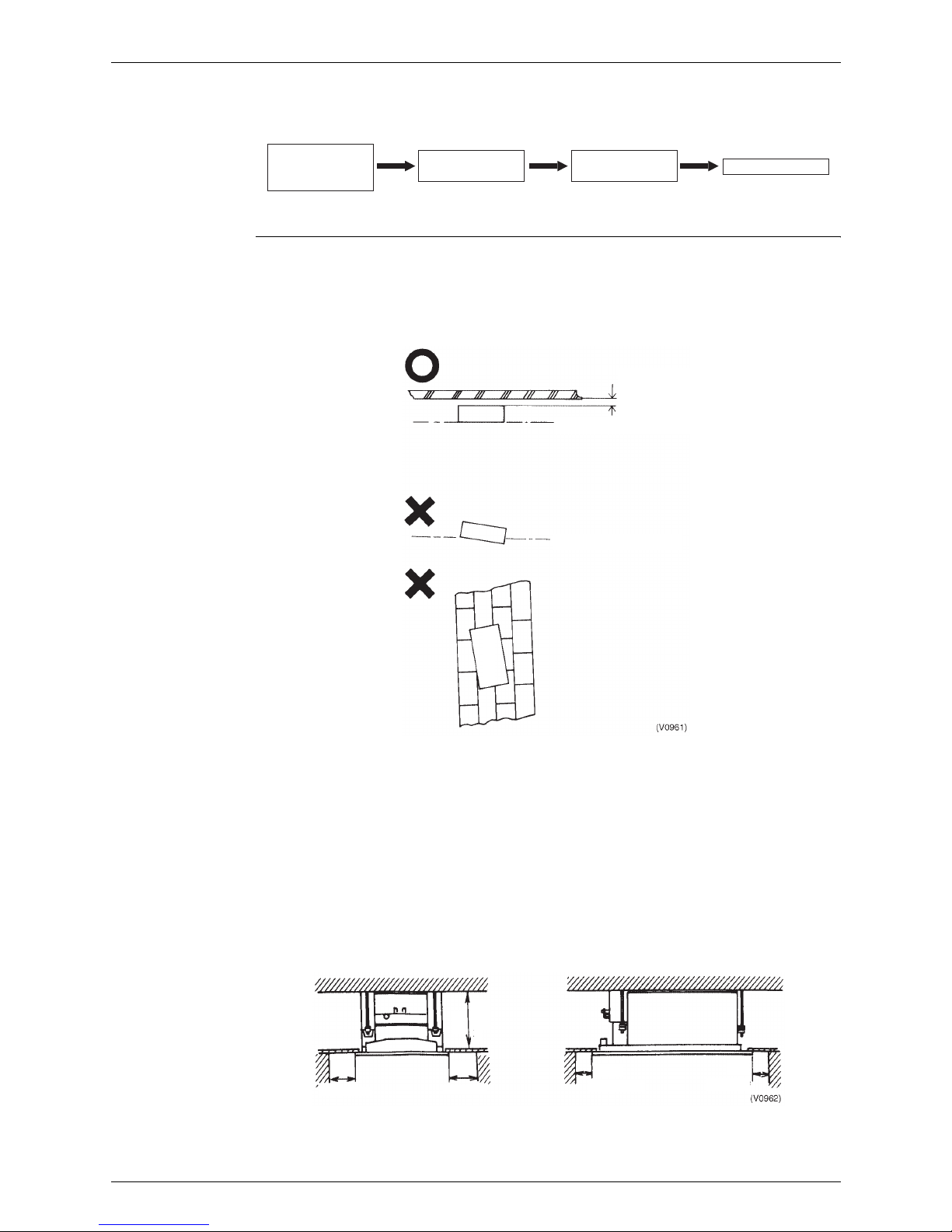
Example: Steel insert
Important point:
1. The weight of the fitting to be suspended must be taken into account when choosing the
insert.
Preliminary talks
with
construction
company
Determine
position, size and
number of units
required
Carry out work Check work
(V0957)
Pillar
D/4
(at least 150mm)
Part of beam
wich must not be piersed
Beam D
Molding box
Suspension bolt
Insert block
Nail securing
molding box
Embedding
depth h
SiEN34-705 Installation
General Information 21
3.2.2 Installation of Indoor Unit
! Operational steps
Positioning 3 essential points when installing an indoor unit
1. Height: Take care to account for final ceiling facing surface level
2. Level: Level fitting is essential. (within ±1 degree of horizontal)
3. Direction: The unit must be fitted in line with the ultimately visible ceiling joints
Important points
1. The suspension bolts must be strong enough to support the weight of the indoor unit.
2. Optional features must be added to the indoor unit prior to installation.
3. The model name should be checked prior to installation.
4. Take care to align the main unit correctly. (Bearing in mind piping layout and direction of
blow out)
5. Leave sufficient space for servicing to be carried out.
6. Make inspection holes for model which need them.
7. Fit the unit to ensure proper drainage.
Example: Ceiling mounted cassette type (FXCQ63M)
Determine
installation
position
Fit indoor unit
Mark installation
position
Fit suspension
bolts
(V0960)
Leave a gap of
at least 3cm
(leave pleanty
of room)
Surface of ceiling facing
Surface of ceiling facing
Indoor unit
1500
or more
1500
or more
100
or more
100
or more
400
or more
Installation SiEN34-705
22 General Information
3.2.3 Refrigerant Pipe Work
! Operational steps
The 3 Principles
of Refrigerant
Piping
The “3 principles of refrigerant piping” must be strictly observed
Fit pipes
provisionally
Install indoor unit
Solder Flushing Air tight test Vacuum drying
Cut pipes to size Replace nitrogen
(V0963)
The 3 principles of refrigerant piping
Dry Clean Air tight
Make sure there is no moisture
inside the pipes
Make sure there is no dirt inside the
pipe
Make sure the refrigerant does not
leak out
Actoin to avoid problemCause of problem
Rainwater, work water, etc.
gets into pipes from outside
Moisture generated inside
pipes due to condensation
Formation of oxides inside
pipes during soldering
Dirt, dust or other
extraneous material gets
into pipes from outside
Leak from soldered area
Leak from flared area
Leak from flange area
Pipe covering Flushing
Replace nitrogen
Pipe covering
Air tight test
Flushing
Vacuum drying
Use the proper materials (copper pipe,
solder, etc.)
Adhere strictly to standard soldering
work practice
Adhere strictly to standard flaring work
practice
Adhere strictly to standard flange
connection work parctice
Clean
Dry
Air tight
(V0964)
Moisture
Dirt
Leak

SiEN34-705 Installation
General Information 23
Method for
Replacing
Nitrogen
(Brazing)
If brazing work is carried out without passing nitrogen gas through the pipes which are being
brazed then this allows the formation of oxidation bubbles on the inside surface of the pipes.
These oxidation bubbles are then carried along inside the pipes to cause damage to various
members of the system such as valves or compressors and the system ceases to function
properly.
In order to avoid this problem nitrogen is passed through the pipes while the soldering
work is being carried out. This operation is known as nitrogen replacement. (Air is replaced by
nitrogen)
This is standard work practice for all brazing work.
Important points:
1. The gas used must be nitrogen (oxygen, carbon dioxide and flon should not be used.)
2. A pressure regulator must be used.
Brazing section
Nitrogen
Taping
Presure regulator
Copper pipe 1 / 4
Packless valve
High pressure hose
Nitrogen cylinder
Outdoor unit
Packless valve
Pipe
Hose
Pressure
regulator
Nitrogen cylinder
Installation SiEN34-705
24 General Information
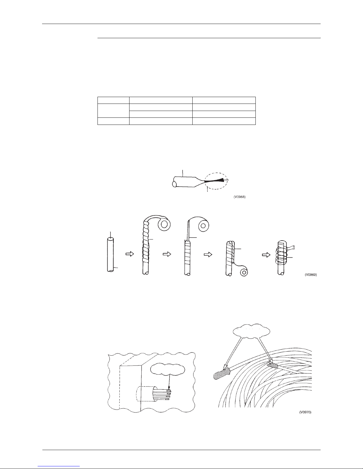
Covering of
Refrigerant Pipes
Covering is an extremely important operation as it prevents water, dirt or dust from
getting inside the pipes. Moisture inside the pipes was a constant source of trouble in the
past. The utmost care is required to nip this problem in the bud.
The end of each pieces of pipe must be covered. “Pinching” is the most effective method but
“taping” is an simple alternative which may be used according to the work area and term of
work.
1. Pinching method
The end of the copper pipe is squeezed together and the gap brazed.
2. Taping method
The end of the copper pipe is covered with PVC tape (vinyl tape).
<Taping method>
Particular care should be taken during the following operations:
! When passing copper pipe through a penetration hole (Dirt easily gets into the pipe).
! When copper pipe is located outside (Rainwater gets in)
(Special care is needed when the pipes are standing vertically outside).
Location Term of Work Covering Method
Outdoors 1 months or more Pinching
Less than 1 months Pinching or taping
Indoors Irrelevant Pinching or taping
Copper pipe
Brazed
Brazing area
Copper
pipe
Open end
Squeeze flat
PVC tape
Bring tape back
to starting point
Tape round
pipe again
Outdoors
Through hole
Indoors
Stored piping should
also be covered
Covering of
pipe ends
 Loading...