

Daikin RXYQ72PYDN, RXYQ96PTJU, RXYQ120PTJU, RXYQ168PTJU, RXYQ144PTJU Service Manual
...
SiUS34 - 801A_b
RXYQ72, 96, 120PYDN
RXYQ72, 96, 120PTJU
RXYQ72-240PYDN, PTJU
R-410A Heat Pump 60Hz
REYQ72-240PYDN, PTJU
R-410A Heat Recovery 60Hz
RXYQ144-240PYDN
RXYQ168-240PTJU
REYQ72, 96, 120PYDN
REYQ72, 96, 120, 144PTJU
RXYQ144PTJU
REYQ144-240PYDN
REYQ168-240PTJU

SiUS34-801A_b
Part 1
General Information1
R-410A Heat Pump/
Heat Recovery
60Hz
1. Introduction .............................................................................................. vii
1.1 Safety Considerations ................................................................................vii
1.2 PREFACE .................................................................................................. xiii
1. Model Names of Indoor/Outdoor Units........................................................2
2. External Appearance...................................................................................3
2.1 Indoor Units .................................................................................................. 3
2.2 Outdoor Units ............................................................................................... 4
3. Combination of Outdoor Units.....................................................................5
4. Model Selection...........................................................................................6
Part 2
VRVIII R-410A Heat Pump 60Hz9
1. Specifications ............................................................................................11
1.1 Outdoor Units ............................................................................................. 11
2. Refrigerant Circuit ....................................................................................17
2.1 RXYQ72P, 96P, 120P ................................................................................ 17
2.2 RXYQ144PTJU .......................................................................................... 18
3. Functional Parts Layout RXYQ72P, 96P, 120P ........................................21
3.1 RXYQ144PTJU .......................................................................................... 21
4. Refrigerant Flow for Each Operation Mode...............................................23
5. Function General.......................................................................................41
5.1 Symbol ....................................................................................................... 41
5.2 Operation Mode.......................................................................................... 42
6. Basic Control.............................................................................................43
6.1 Normal Operation ....................................................................................... 43
6.2 Compressor PI Control............................................................................... 44
6.3 Electronic Expansion Valve PI Control....................................................... 47
6.4 Step Control of Outdoor Unit Fans ............................................................. 47
6.5 Outdoor Unit Fan Control in Cooling Operation ......................................... 48
6.6 Heat Exchanger Control............................................................................. 49
7. Special Control..........................................................................................50
7.1 Startup Control ........................................................................................... 50
Table of Contents i

SiUS34-801A_b
7.2 Large Capacity Start Up Control (Heating)................................................. 51
7.3 Oil Return Operation .................................................................................. 52
7.4 Defrost Operation ....................................................................................... 56
7.5 Pump-down Residual Operation ................................................................ 58
7.6 Standby ...................................................................................................... 60
7.7 Stopping Operation .................................................................................... 61
8. Protection Control .....................................................................................63
8.1 High Pressure Protection Control............................................................... 63
8.2 Low Pressure Protection Control................................................................ 65
8.3 Discharge Pipe Protection Control ............................................................. 67
8.4 Inverter Protection Control ......................................................................... 68
8.5 STD Compressor Overload Protection....................................................... 70
9. Other Control.............................................................................................71
9.1 Backup Operation....................................................................................... 71
9.2 Demand Operation ..................................................................................... 71
9.3 Heating Operation Prohibition .................................................................... 71
10.Test Operation ..........................................................................................72
10.1 Installation Process .................................................................................... 72
10.2 Procedure and Outline ............................................................................... 73
10.3 Operation when Power is Turned On ......................................................... 91
11.Outdoor Unit PC Board Layout .................................................................93
12.Field Settings ............................................................................................94
12.1 Field Settings on the Outdoor Unit ............................................................. 94
Part 3
VRVIII R-410A Heat Recovery 60Hz119
1. Specifications ..........................................................................................121
1.1 Outdoor Units ........................................................................................... 121
1.2 BS Units ................................................................................................... 126
2. Refrigerant Circuit ...................................................................................128
2.1 REYQ72, 96, 120PYDN, PTJU ................................................................ 128
2.2 REYQ144PTJU ........................................................................................ 130
2.3 REMQ72PYDN, PTJU (Multi 6ton)........................................................... 132
2.4 REMQ96, 120PYDN, PTJU (Multi 8, 10ton)............................................. 134
2.5 BS Unit Functional Parts .......................................................................... 136
3. Functional Parts Layout ..........................................................................137
3.1 REYQ72P, 96P, 120P .............................................................................. 137
3.2 REYQ144PTJU ........................................................................................ 138
3.3 REMQ72P ................................................................................................ 139
3.4 REMQ96P, 120P...................................................................................... 140
4. Refrigerant Flow for Each Operation Mode.............................................141
5. Function General.....................................................................................185
5.1 Symbol ..................................................................................................... 185
5.2 Operation Mode........................................................................................ 187
6. Basic Control...........................................................................................188
ii Table of Contents

SiUS34-801A_b
6.1 Normal Operation ..................................................................................... 188
6.2 Compressor PI Control............................................................................. 189
6.3 Electronic Expansion Valve PI Control..................................................... 193
6.4 Step Control of Outdoor Unit Fans ........................................................... 194
6.5 Outdoor Unit Fan Control in Cooling Operation ....................................... 194
6.6 Heat Exchanger Control........................................................................... 195
7. Special Control........................................................................................197
7.1 Startup Control ......................................................................................... 197
7.2 Large Capacity Start Up Control (Heating)............................................... 198
7.3 Oil Return Operation ................................................................................ 199
7.4 Defrost Operation ..................................................................................... 203
7.5 Pump-down Residual Operation .............................................................. 205
7.6 Standby .................................................................................................... 207
7.7 Stopping Operation .................................................................................. 208
8. Protection Control ...................................................................................210
8.1 High Pressure Protection Control............................................................. 210
8.2 Low Pressure Protection Control.............................................................. 211
8.3 Discharge Pipe Protection Control ........................................................... 213
8.4 Inverter Protection Control ....................................................................... 214
8.5 STD Compressor Overload Protection..................................................... 216
9. Other Control...........................................................................................218
9.1 Backup Operation..................................................................................... 218
9.2 Demand Operation ................................................................................... 218
9.3 Heating Operation Prohibition .................................................................. 218
10.Test Operation ........................................................................................219
10.1 Installation Process .................................................................................. 219
10.2 Procedure and Outline ............................................................................. 219
10.3 Operation when Power is Turned On ....................................................... 238
11.Outdoor Unit PC Board Layout ...............................................................240
12.Field Setting ............................................................................................241
12.1 Field Setting from Outdoor Unit................................................................ 241
Part 4 Indoor Unit.........................................................................269
1. Specifications ..........................................................................................270
2. Refrigerant Circuit ...................................................................................284
3. Operation Flow Chart ..............................................................................285
4. Thermostat Sensor in Remote Controller................................................287
4.1 Thermostat Control While in Normal Operation ....................................... 289
4.2 Thermostat Control in Dry Operation ....................................................... 289
4.3 Thermostat Control with Operation Mode Set to AUTO........................... 290
5. Drain Pump Control.................................................................................291
5.1 When the Float Switch is Tripped while the Cooling Thermostat is ON:.. 291
5.2 When the Float Switch is Tripped while the Cooling Thermostat is OFF: 291
5.3 When the Float Switch is Tripped During Heating Operation:.................. 292
5.4 When the Float Switch is Tripped and “AF” is Displayed on the Remote Con-
troller: ....................................................................................................... 292
Table of Contents iii

Part 5
SiUS34-801A_b
6. Control of Electronic Expansion Valve ....................................................293
7. Freeze Prevention...................................................................................294
8. Heater Control (Optional PC Board KRP1B ... is required.).................... 295
9. List of Louver Operations ........................................................................296
10.Hot Start Control (In Heating Operation Only) ........................................297
11.Louver Control for Preventing Ceiling Dirt...............................................298
12.Field Setting ............................................................................................299
12.1 Field Setting from Remote Controller ....................................................... 299
Troubleshooting ................................................................315
1. Symptom-based Troubleshooting ..........................................................318
2. Troubleshooting by Remote Controller ...................................................321
2.1 The INSPECTION / TEST Button............................................................. 321
2.2 Self-diagnosis by Wired Remote Controller ............................................. 322
2.3 Self-diagnosis by Wireless Remote Controller......................................... 323
2.4 Inspection Mode ....................................................................................... 326
2.5 Remote Controller Service Mode ............................................................. 327
2.6 Test Run Mode......................................................................................... 329
2.7 Remote Controller Self-Diagnosis Function ............................................. 329
3. Troubleshooting by Indication on the Remote Controller ........................336
3.1 A0 Indoor Unit: Error of External Protection Device................................. 336
3.2 A1 Indoor Unit: PC Board Defect ............................................................ 337
3.3 A3 Indoor Unit: Malfunction of Drain Level Control System (S1L) .......... 338
3.4 A6 Indoor Unit: Fan Motor (M1F) Lock, Overload ..................................... 340
3.5 A7 Indoor Unit: Malfunction of Louver Motor (M1S)............................... 344
3.6 A9 Indoor Unit: Electronic Expansion Valve
Malfunction / Dust Clogging ..................................................................... 346
3.7 AF Indoor Unit: Drain Level above Limit.................................................. 350
3.8 AJ Indoor Unit: Malfunction of Capacity Determination Device................ 351
3.9 C4 Indoor Unit: Malfunction of Thermistor (R2T) for Heat Exchanger..... 352
3.10 C5 Indoor Unit: Malfunction of Thermistor (R3T) for Gas Pipes................ 353
3.11 C9 Indoor Unit: Malfunction of Thermistor (R1T) for Suction Air............... 354
3.12 CJ Indoor Unit: Malfunction of Thermostat Sensor in Remote Controller 355
3.13 E1 Outdoor Unit: PC Board Defect.......................................................... 356
3.14 E2 Outdoor Unit: Detection of ground leakage by leak detection PC board
ass’y ......................................................................................................... 357
3.15 E3 Outdoor Unit: Actuation of High Pressure Switch .............................. 359
3.16 E4 Outdoor Unit: Actuation of Low Pressure Sensor .............................. 361
3.17 E5 Outdoor Unit: Inverter Compressor Motor Lock................................. 363
3.18 E6 Outdoor Unit: STD Compressor Motor Overcurrent/Lock .................. 365
3.19 E7 Outdoor Unit: Malfunction of Outdoor Unit Fan Motor ....................... 367
3.20 E9 Outdoor Unit: Malfunction of Moving Part of Electronic Expansion Valve
(Y1E~Y5E) ............................................................................................... 370
3.21 F3 Outdoor Unit: Abnormal Discharge Pipe Temperature ...................... 372
3.22 F6 Outdoor Unit: Refrigerant Overcharged............................................. 374
iv Table of Contents

SiUS34-801A_b
3.23 H7 Outdoor Unit: Abnormal Outdoor Fan Motor Signal............................ 375
3.24 H9 Outdoor Unit: Malfunction of Thermistor (R1T) for Outdoor Air ......... 377
3.25 J2 Outdoor Unit: Current Sensor Malfunction......................................... 378
3.26 J3 Outdoor Unit: Malfunction of Discharge Pipe Thermistor (R31, 32T) . 380
3.27 J4 Outdoor Unit: Malfunction of Temperature Sensor for Heat Exchanger Gas
(R2T or R11T) .......................................................................................... 381
3.28 J5 Outdoor Unit: Malfunction of Thermistor (R8T or R10T) Suction Pipe. 382
3.29 J6 Outdoor Unit: Malfunction of Thermistor (R4T or R12T) for Outdoor Unit
Heat Exchanger........................................................................................ 383
3.30 J7 Outdoor Unit: Malfunction of Liquid Pipe Thermistor 1 (R6T), (R9T) or
(R14T) ...................................................................................................... 384
3.31 J8 Outdoor Unit: Malfunction of Liquid Pipe Thermistor 2 (R7T or R15T) 385
3.32 J9 Outdoor Unit: Malfunction of Subcooling Heat Exchanger Gas Pipe Ther-
mistor (R5T or R13T) ............................................................................... 386
3.33 JA Outdoor Unit: Malfunction of High Pressure Sensor............................ 387
3.34 JC Outdoor Unit: Malfunction of Low Pressure Sensor............................. 389
3.35 L1 Outdoor Unit: Defective Inverter PC Board.......................................... 391
3.36 L4 Outdoor Unit: Malfunction of Inverter Radiating Fin Temperature Rise393
3.37 L5 Outdoor Unit: Momentary Overcurrent of Inverter Compressor........... 396
3.38 L8 Outdoor Unit: Momentary Overcurrent of Inverter Compressor........... 398
3.39 L9 Outdoor Unit: Inverter Compressor Starting Failure ............................ 400
3.40 LC Outdoor Unit: Malfunction of Transmission between Inverter and Control
PC Board.................................................................................................. 403
3.41 P1 Outdoor Unit: Inverter Over-Ripple Protection ..................................... 406
3.42 P4 Outdoor Unit: Malfunction of Inverter Radiating Fin Temperature Rise Sen-
sor ............................................................................................................ 408
3.43 PJ Outdoor Unit: Faulty Field Setting after Replacing Main PC Board or Faulty
Combination of PC Board......................................................................... 410
3.44 U0 Outdoor Unit: Gas Shortage Alert........................................................ 412
3.45 U1 Reverse Phase, Open Phase .............................................................. 414
3.46 U2 Outdoor Unit: Power Supply Insufficient or Instantaneous Failure ...... 415
3.47 U3 Outdoor Unit: Check Operation not Executed...................................... 418
3.48 U4 Malfunction of Transmission between Indoor Units ............................. 419
3.49 U5 Indoor Unit: Malfunction of Transmission between Remote Controller and
Indoor Unit................................................................................................ 424
3.50 U7 Outdoor Unit: Transmission Failure (Across Outdoor Units)................ 425
3.51
U8 Indoor Unit: Malfunction of Transmission between Main and Sub Remote
Controllers ................................................................................................ 431
3.52 U9 Indoor Unit: Malfunction of Transmission between Indoor and Outdoor
Units in the Same System ........................................................................ 432
3.53 UA Improper Combination of Indoor and Outdoor Units, Indoor Units and Re-
mote Controller......................................................................................... 433
3.54 UC Address Duplication of Centralized Controller ..................................... 439
3.55 UE Malfunction of Transmission between Centralized Controller and Indoor
Unit ........................................................................................................... 440
3.56 UF System is not Set yet ........................................................................... 443
3.57 UH Malfunction of System, Refrigerant System Address Undefined ......... 444
4. Troubleshooting (OP: Central Remote Controller) ..................................446
Table of Contents v

SiUS34-801A_b
4.1 M1 PC Board Defect ................................................................................. 446
4.2 M8 Malfunction of Transmission between Optional Controllers for Centralized
Control...................................................................................................... 447
4.3 MA Improper Combination of Optional Controllers for Centralized Control449
4.4 MC Address Duplication, Improper Setting................................................ 451
5. Troubleshooting (OP: Unified ON/OFF Controller) .................................453
5.1 Operation Lamp Blinks ............................................................................. 453
5.2 Display [Under Centralized Control] Blinks (Repeats Single Blink).......... 455
5.3 Display [Under Centralized Control] Blinks (Repeats Double Blink) ........ 458
Part 6 Appendix............................................................................473
1. Piping Diagrams......................................................................................474
1.1 Outdoor Unit ............................................................................................. 474
1.2 Indoor Unit................................................................................................ 484
1.3 BS Unit ..................................................................................................... 486
2. Wiring Diagrams for Reference...............................................................487
2.1 Outdoor Unit ............................................................................................. 487
2.2 Field Wiring .............................................................................................. 497
2.3 Indoor Unit................................................................................................ 505
2.4 BS Unit BSVQ36P/60PVJU..................................................................... 509
3. List of Electrical and Functional Parts .....................................................510
3.1 Outdoor Unit ............................................................................................. 510
3.2 Indoor Side ............................................................................................... 514
4. Option List ...............................................................................................518
4.1 Option List of Controllers.......................................................................... 518
4.2 Option Lists (Outdoor Unit)....................................................................... 519
5. Piping Installation Point...........................................................................520
5.1 Piping between Outside Units .................................................................. 520
6. Thermistor Resistance / Temperature Characteristics............................523
7. Pressure Sensor .....................................................................................525
8. Method of Checking Inverter’s Power Transistors & Diode Modules ...... 526
9. Example of Connection ...........................................................................529
Part 7 Precautions for New Refrigerant (R-410A).......................535
1. Precautions for New Refrigerant (R-410A) .............................................536
1.1 Service Tools............................................................................................ 538
Index ................................................................................................i
Drawings & Flow Charts ......................................................iv
vi Table of Contents
Introduction SiUS34-801A_b
1. Introduction
1.1 Safety Considerations
Cautions and
Warnings
Read these SAFETY CONSIDERATIONS carefully before installing air conditioning equipment, and be
sure to install it correctly. After completing the installation, make sure that the unit operates properly during
the start-up operation.
Instruct the customer how to operate and maintain the unit.
Inform customers that they should store this Installation Manual with the Operation Manual for future ref-
erence.
Always use a licensed installer or contractor to install this product. Improper installation can result in water
or refrigerant leakage, electrical shock, fire, or explosion.
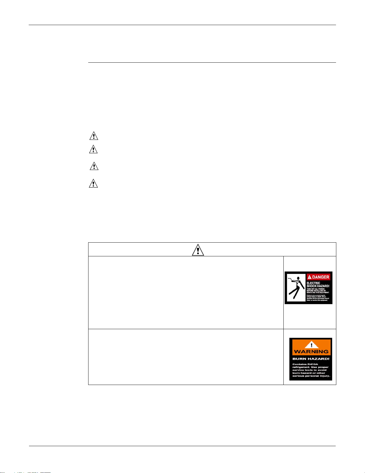
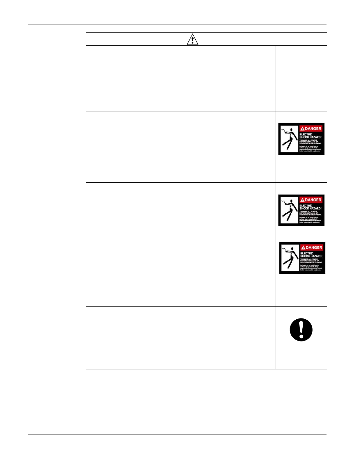
Meanings of DANGER, WARNING, CAUTION, and NOTE Symbols:
DANGER ............... Indicates an imminently hazardous situation which, if not avoided, will result in
WARNING ............. Indicates a potentially hazardous situation which, if not avoided, could result in
CAUTION .............. Indicates a potentially hazardous situation which, if not avoided, may result in
NOTE .....................Indicates situations that may result in equipment or property-damage
accidents only.
conducting conducting repair work.
1.1.1 Caution in Repair
death or serious injury.
death or serious injury.
minor or moderate injury. It may also be used to alert against unsafe practices.
Be sure to read the following safety cautions before
Warning
Be sure to disconnect the power cable plug from the plug socket before
disassembling the equipment for a repair.
Working on the equipment that is connected to a power supply can cause an
electrical shock.
If it is necessary to supply power to the equipment to conduct the repair or
inspecting the circuits, do not touch any electrically charged sections of the
equipment.
If the refrigerant gas discharges during the repair work, do not touch the
discharging refrigerant gas.
The refrigerant gas can cause frostbite.
vii
SiUS34-801A_b
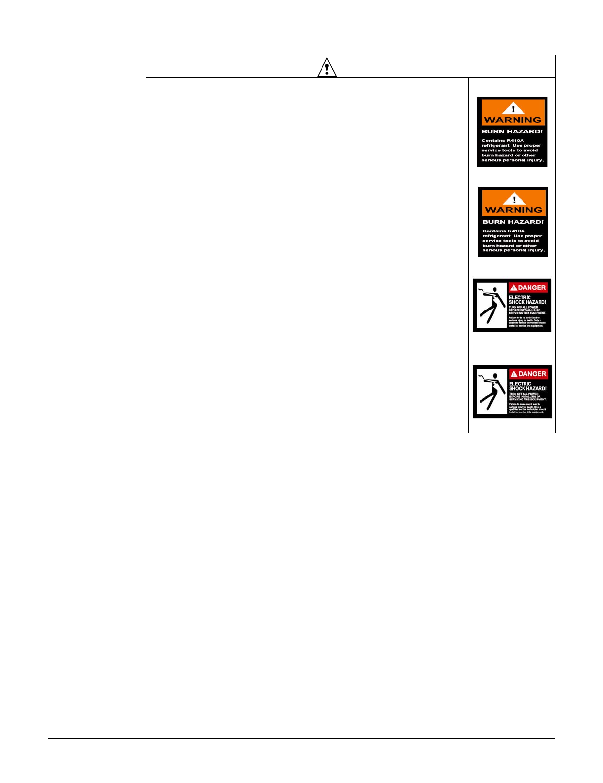
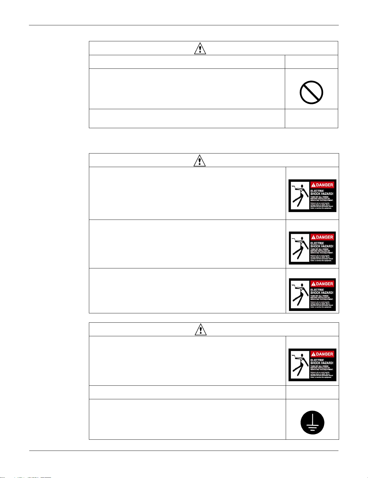
Warning
When disconnecting the suction or discharge pipe of the compressor at the
welded section, release the refrigerant gas completely at a well-ventilated place
first.
If there is a gas remaining inside the compressor, the refrigerant gas or
refrigerating machine oil discharges when the pipe is disconnected, and it can
cause injury.
If the refrigerant gas leaks during the repair work, ventilate the area. The
refrigerant gas can generate toxic gases when it contacts flames.
The step-up capacitor supplies high-voltage electricity to the electrical
components of the outdoor unit.
Be sure to discharge the capacitor completely before conducting repair work.
A charged capacitor can cause an electrical shock.
Do not start or stop the air conditioner operation by plugging or unplugging the
power cable plug.
Plugging or unplugging the power cable plug to operate the equipment can cause
an electrical shock or fire.
viii
Introduction SiUS34-801A_b
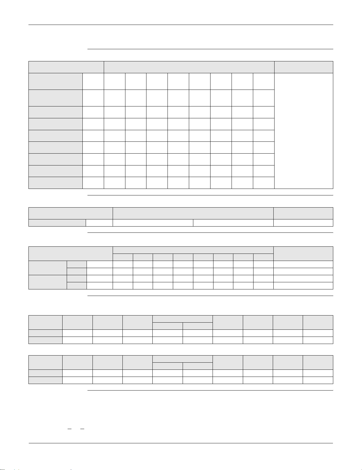
Caution
Do not repair the electrical components with wet hands.
Working on the equipment with wet hands can cause an electrical shock.
Do not clean the air conditioner by splashing water.
Washing the unit with water can cause an electrical shock.
Be sure to provide the grounding when repairing the equipment in a humid or wet
place, to avoid electrical shocks.
Be sure to turn off the power switch and unplug the power cable when cleaning
the equipment.
The internal fan rotates at a high speed, and can cause injury.
Do not tilt the unit when removing it.
The water inside the unit can spill and wet the furniture and floor.
Be sure to check that the refrigerating cycle section has cooled down sufficiently
before conducting repair work.
Working on the unit when the refrigerating cycle section is hot can cause burns.
Use the welder in a well-ventilated place.
Using the welder in an enclosed room can cause oxygen deficiency.
1.1.2 Cautions Regarding Products after Repair
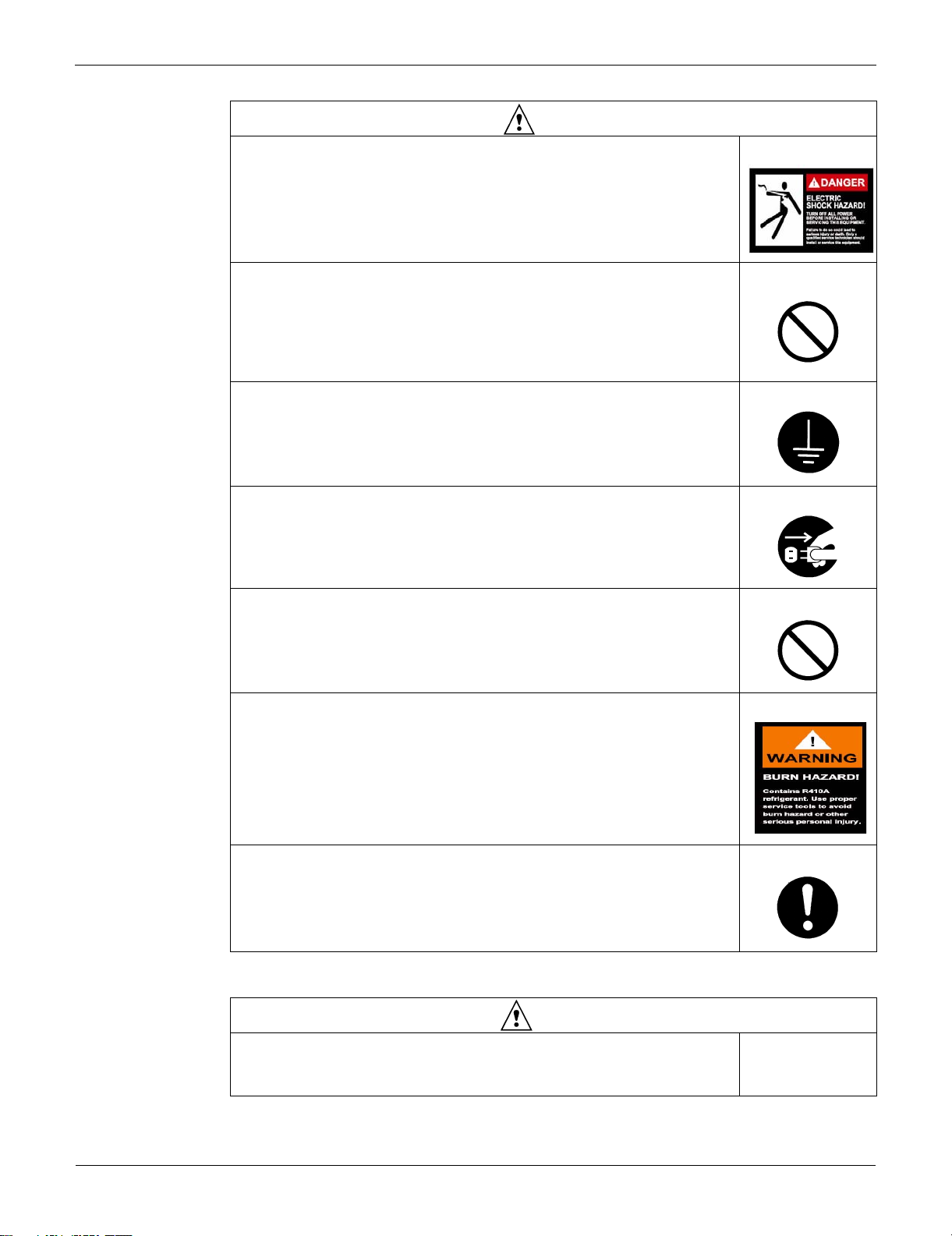
Warning
Be sure to use parts listed in the service parts list of the applicable model and
appropriate tools to conduct repair work. Never attempt to modify the equipment.
The use of inappropriate parts or tools can cause an electrical shock, excessive
heat generation or fire.
ix
SiUS34-801A_b
Warning
When relocating the equipment, make sure that the new installation site has
sufficient strength to withstand the weight of the equipment.
If the installation site does not have sufficient strength and if the installation work
is not conducted securely, the equipment can fall and cause injury.
Be sure to install the product correctly by using the provided standard installation
frame.
Incorrect use of the installation frame and improper installation can cause the
equipment to fall, resulting in injury.
Be sure to install the product securely in the installation frame mounted on a
window frame.
If the unit is not securely mounted, it can fall and cause injury.
Be sure to use an exclusive power circuit for the equipment, and follow the
technical standards related to the electrical equipment, the internal wiring
regulations and the instruction manual for installation when conducting electrical
work.
Insufficient power circuit capacity and improper electrical work can cause an
electrical shock or fire.
Be sure to use the specified cable to connect between the indoor and outdoor
units. Make the connections securely and route the cable properly so that there is
no force pulling the cable at the connection terminals.
Improper connections can cause excessive heat generation or fire.
When connecting the cable between the indoor and outdoor units, make sure that
the terminal cover does not lift off or dismount because of the cable.
If the cover is not mounted properly, the terminal connection section can cause an
electrical shock, excessive heat generation or fire.
For integral units
only
For integral units
only
Do not damage or modify the power cable.
Damaged or modified power cable can cause an electrical shock or fire.
Placing heavy items on the power cable, and heating or pulling the power cable
can damage the cable.
Do not mix air or gas other than the specified refrigerant (R-410A) in the refrigerant
system.
If air enters the refrigerating system, an excessively high pressure results, causing
equipment damage and injury.
If the refrigerant gas leaks, be sure to locate the leak and repair it before charging
the refrigerant. After charging refrigerant, make sure that there is no refrigerant
leak.
If the leak cannot be located and the repair work must be stopped, be sure to
perform pump-down and close the service valve, to prevent the refrigerant gas
from leaking into the room. The refrigerant gas itself is harmless, but it can
generate toxic gases when it contacts flames, such as fan and other heaters,
stoves and ranges.
When replacing the coin battery in the remote controller, be sure to dispose of the
old battery to prevent children from swallowing it.
If a child swallows the coin battery, see a doctor immediately.
x
Introduction SiUS34-801A_b
Caution
Installation of a leakage breaker is necessary in some cases depending on the
conditions of the installation site, to prevent electrical shocks.
Do not install the equipment in a place where there is a possibility of combustible
gas leaks.
If a combustible gas leaks and remains around the unit, it can cause a fire.
Be sure to install the packing and seal on the installation frame properly.
If the packing and seal are not installed properly, water can enter the room and
wet the furniture and floor.
1.1.3 Inspection after Repair
Check to make sure that the power cable plug is not dirty or loose, then insert the
plug into a power outlet all the way.
If the plug has dust or loose connection, it can cause an electrical shock or fire.
If the power cable and lead wires have scratches or have deteriorated, be sure to
replace them.
Damaged cable and wires can cause an electrical shock, excessive heat
generation or fire.
Do not use a joined power cable or extension cable, or share the same power
outlet with other electrical appliances, since it can cause an electrical shock,
excessive heat generation or fire.
For integral units
only
Warning
Caution
Check to see if the parts and wires are mounted and connected properly, and if
the connections at the soldered or crimped terminals are secure.
Improper installation and connections can cause excessive heat generation, fire
or an electrical shock.
If the installation platform or frame has corroded, replace it.
Corroded installation platform or frame can cause the unit to fall, resulting in injury.
Check the grounding, and repair it if the equipment is not properly grounded.
Improper grounding can cause an electrical shock.
xi

SiUS34-801A_b
Caution
Be sure to measure the insulation resistance after the repair, and make sure that
the resistance is 1 ohm or higher.
Faulty insulation can cause an electrical shock.
Be sure to check the drainage of the indoor unit after the repair.
Faulty drainage can cause the water to enter the room and wet the furniture and
floor.
xii

Introduction SiUS34-801A_b
1.2 PREFACE
Thank you for your continued patronage of Daikin products.
This is the new service manual for Daikin's Year 2008 VRVIII series Heat Pump System.
Daikin offers a wide range of models to respond to building and office air conditioning needs.
We are confident that customers will be able to find the models that best suit their needs.
This service manual contains information regarding the servicing of VRVIII series Heat Pump, Heat
Recovery System.
May, 2008
After Sales Service Division
xiii

SiUS34-801A_b
xiv

SiUS34-801A_b
Part 1
General Information
1. Model Names of Indoor/Outdoor Units........................................................2
2. External Appearance...................................................................................3
2.1 Indoor Units .................................................................................................. 3
2.2 Outdoor Units ............................................................................................... 4
3. Combination of Outdoor Units.....................................................................5
4. Model Selection...........................................................................................6
General Information 1
Model Names of Indoor/Outdoor Units SiUS34-801A_b
1. Model Names of Indoor/Outdoor Units
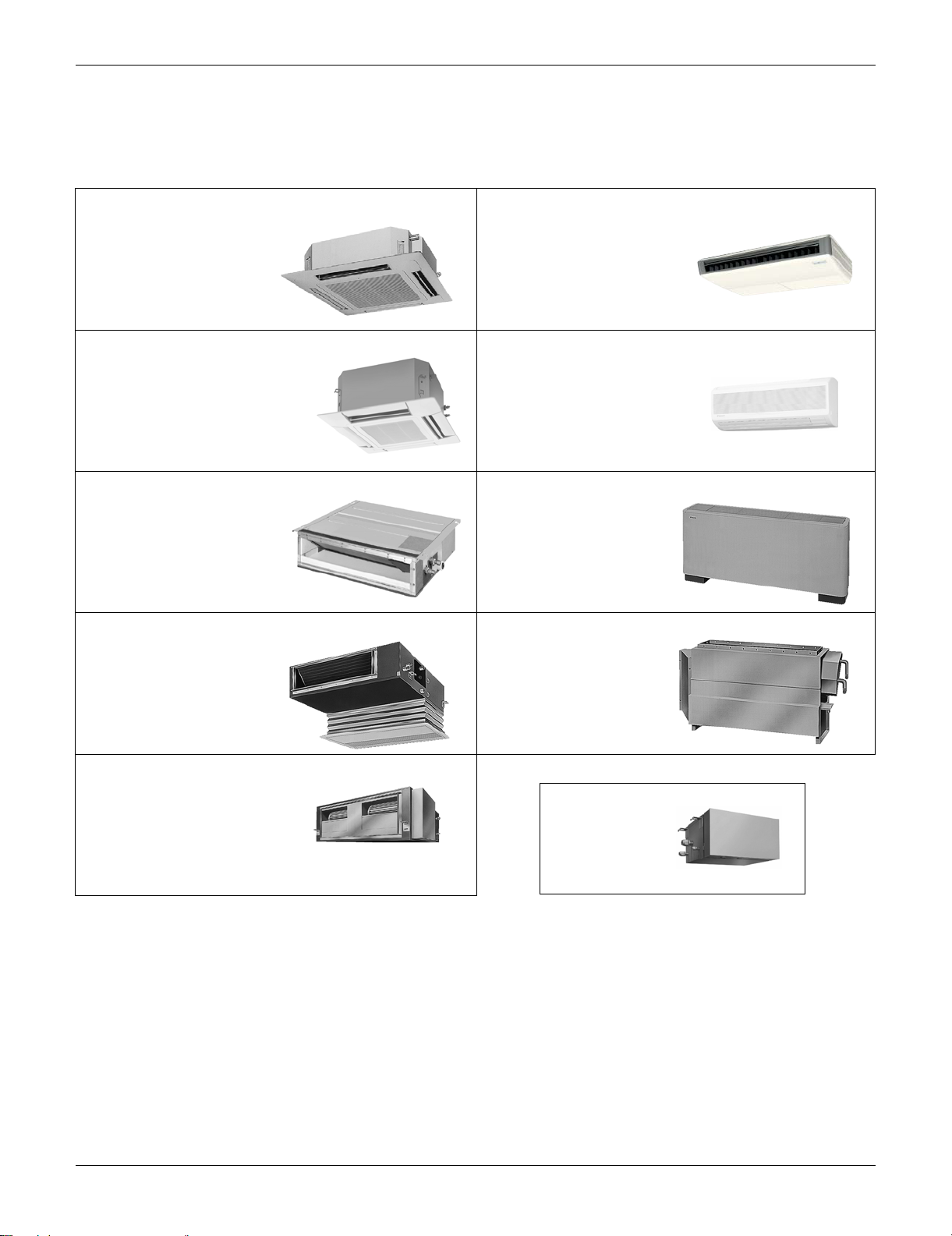
Indoor Units
Type Model Name
Ceiling-Mounted
Cassette Type
(Multi Flow)
4 Way Ceiling Mounted
Cassette Type Unit
(2’×2’)
Slim Ceiling-Mounted
Duct Type
Ceiling Mounted
Built-In Type
Ceiling Mounted
Duct Type
Ceiling Suspended
Type
Wall Mounted Type FXAQ 07M 09M 12M 18M 24M — — —
Floor Standing Type FXLQ — — 12M 18M 24M — — —
Concealed Floor
Standing Type
FXFQ — — 12M 18M 24M 30M 36M —
FXZQ 07M7 09M7 12M7 18M7 — — — —
FXDQ 07M 09M 12M 18M 24M — — —
FXSQ — — 12M 18M 24M 30M 36M 48M
FXMQ—————30M36M48M
FXHQ — — 12M — 24M — 36M —
FXNQ — — 12M 18M 24M — — —
Power Supply,
Compatibility Symbol
VJU
BS Units
Type Model Name
Heat Recovery Series BSVQ 36P 60P VJU
Power Supply,
Compatibility Symbol
Outdoor Units (Inverter Series)
Heat Pump
Heat Recovery
Type
230V RXYQ- 72P 96P 120P 144P 168P 192P 216P 240P TJU
460V RXYQ- 72P 96P 120P 144P 168P 192P 216P 240P YDN
230V REYQ- 72P 96P 120P 144P 168P 192P 216P 240P TJU
460V REYQ- 72P 96P 120P 144P 168P 192P 216P 240P YDN
6 ton 8 ton 10 ton 12 ton 14 ton 16 ton 18 ton 20 ton
Model Name
Power Supply,
Compatibility Symbol
Combination of Outdoor Units
Heat Pump
Model Name RXYQ72P RXYQ96P RXYQ120P
Outdoor unit 1 RXYQ72P RXYQ96P RXYQ120P RXYQ144P RXYQ72P RXYQ72P RXYQ72P RXYQ96P RXYQ120P
Outdoor unit 2 — — — — RXYQ72P RXYQ96P RXYQ120P RXYQ120P RXYQ120P
RXYQ144P
230V 460V
RXYQ168P RXYQ192P RXYQ216P RXYQ240P
Heat Recovery
Model Name REYQ72P REYQ96P REYQ120P
Outdoor unit 1 REYQ72P REYQ96P REYQ120P REYQ144P REMQ72P REMQ72P REMQ72P REMQ96P REMQ120P
Outdoor unit 2 — — — — REMQ72P REMQ96P REMQ120P REMQ120P REMQ120P
REYQ144P
230V 460V
REYQ168P REYQ192P REYQ216P REYQ240P
VJ: 1φ, 208~230V, 60Hz
YDN: 3φ, 460V, 60Hz
TJ: 3φ, 208~230V, 60Hz
U(VJU
, TJU): Standard Compatibility Symbol
2 General Information
SiUS34-801A_b External Appearance
2. External Appearance
2.1 Indoor Units
2.1.1 Indoor Units Heat Pump, Heat Recovery (60Hz)
Ceiling-mounted cassette type (Multi flow)
FXFQ12MVJU
FXFQ18MVJU
FXFQ24MVJU
FXFQ30MVJU
FXFQ36MVJU
4 way ceiling-mounted cassette unit
(2’×2’)
FXZQ07M7
FXZQ09M7
FXZQ12M7
FXZQ18M7
Slim ceiling-mounted duct type
FXDQ07MVJU
FXDQ09MVJU
FXDQ12MVJU
FXDQ18MVJU
FXDQ24MVJU
Ceiling mounted built-in type
FXSQ12MVJU
FXSQ18MVJU
FXSQ24MVJU
FXSQ30MVJU
FXSQ36MVJU
FXSQ48MVJU
Ceiling suspended type
FXHQ12MVJU
FXHQ24MVJU
FXHQ36MVJU
Wall mounted type
FXAQ07MVJU
FXAQ09MVJU
FXAQ12MVJU
FXAQ18MVJU
FXAQ24MVJU
Floor standing type
FXLQ12MVJU
FXLQ18MVJU
FXLQ24MVJU
Concealed floor standing type
FXNQ12MVJU
FXNQ18MVJU
FXNQ24MVJU
Ceiling-mounted duct type
FXMQ30MVJU
FXMQ36MVJU
FXMQ48MVJU
BS Units
BSVQ36PVJU
BSVQ60PVJU
General Information 3
External Appearance SiUS34-801A_b
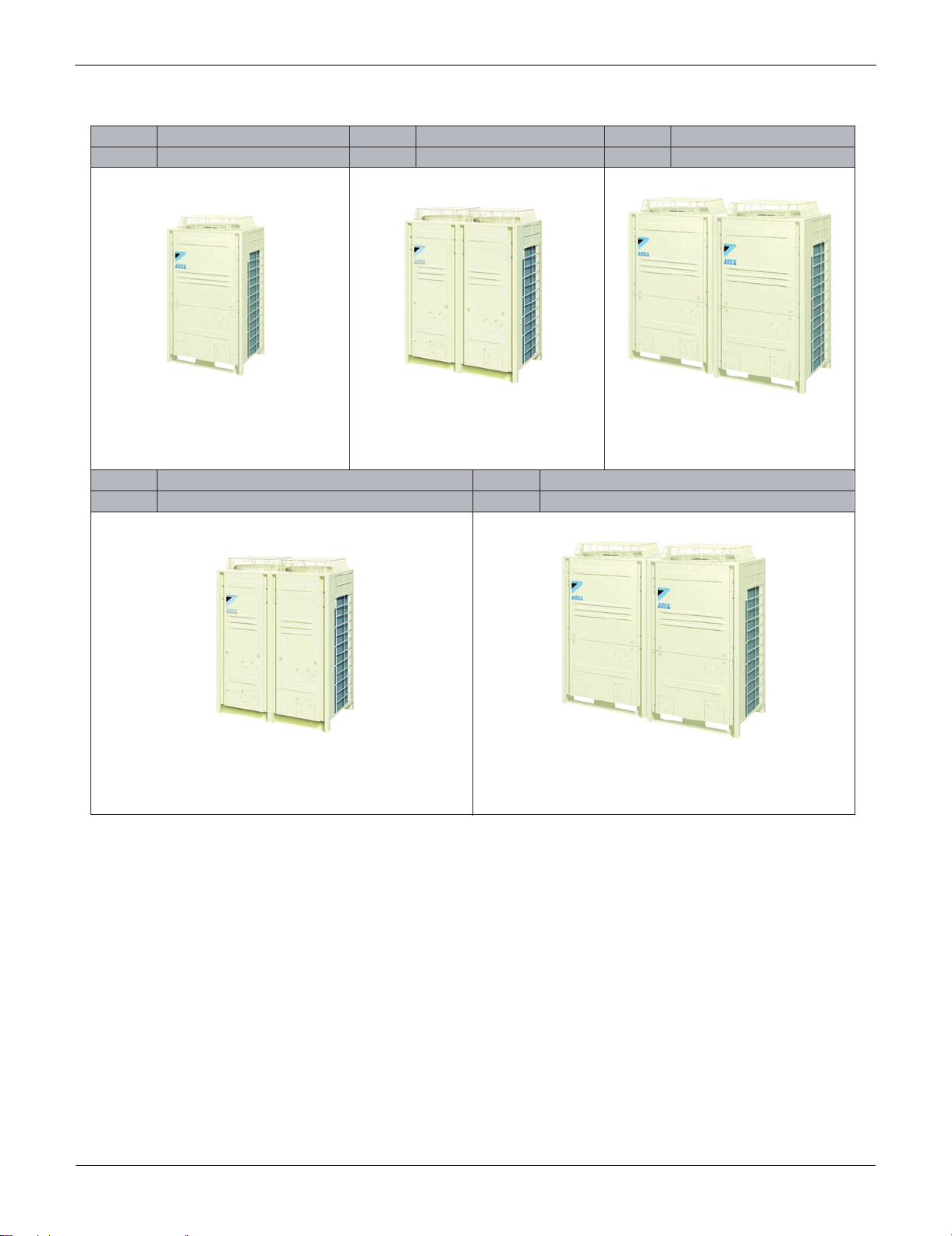
2.2 Outdoor Units
H/P (460V)
H/P (230V)
H/R (460V)
H/R (230V)
RXYQ72P, 96P, 120PYDN
RXYQ72P, 96P, 120PTJU
REYQ72P, 96P, 120PYDN
REYQ72P, 96P, 120P, 144PTJU
—
H/P (230V)
RXYQ144PTJU
H/R (460V)
H/R (230V)
REYQ144P, 168P, 192P, 216P, 240PYDN
H/P (460V)
H/P (230V)
REYQ168P, 192P, 216P, 240PTJU
RXYQ144P, 168P, 192P, 216P, 240PYDN
RXYQ168P, 192P, 216P, 240PTJU
4 General Information

SiUS34-801A_b Combination of Outdoor Units
3. Combination of Outdoor Units
Heat Pump
Single Use
Ton
6 ton 1
8 ton 1
10 ton 1
12 ton
(230V)
Number of
units
1
72 96 120 144
Single Unit
Outdoor Unit Multi Connection
Piping Kit (Option)
—
Multiple Use
Ton
12 ton
(460V)
14 ton 2
16 ton 2
18 ton 2
20 ton 2
Number of
units
2
72 96 120
Multi Unit Module
Outdoor Unit Multi Connection
Piping Kit (Option)
Heat Pump: BHFP22P100U
Heat Recovery
Single Use
Ton
6 ton 1
8 ton 1
10 ton 1
12 ton
(230V)
Number of
units
72 96 120 144
Single Unit
Outdoor Unit Multi Connection
Piping Kit (Option)
—
Multiple Use
Ton
12 ton
(460V)
14 ton 2
16 ton 2
18 ton 2
20 ton 2
Number of
units
2
72 96 120
Multi Unit Module
Outdoor Unit Multi Connection
Piping Kit (Option)
Heat Recovery: BHFP26P90U
Note: For multiple connection of 12 ton system or more, an optional Daikin Outdoor Unit Multi Connection
Piping Kit is required.
General Information 5
Model Selection SiUS34-801A_b
4. Model Selection
VRVIII Series
Connectable Indoor Units Number and Capacity
Heat Pump
Ton 6 ton 8 ton 10 ton
System name RXYQ72P RXYQ96P
Outdoor unit 1 RXYQ72P RXYQ96P
Outdoor unit 2
Total number
of connectable indoor units
Total Capacity Index
of Indoor Units to be Connected
————
12 16 20 24 24 29 33 37 41
36~93.5 48~124.5 60~156 72~187 72~187 84~218 96~249.5
Heat Recovery
Ton 6ton 8ton 10ton
System name REYQ72P REYQ96P
Outdoor unit 1 REYQ72P REYQ96P
Outdoor unit 2
Total number
of connectable indoor units
Total Capacity Index
of Indoor Units to be Connected
————
12 16 20 24 24 29 33 37 41
36~93.5 48~124.5 60~156 72~187 72~187 84~218 96~249.5
RXYQ120P
RXYQ120P
REYQ120P
REYQ120P
12 ton
(230V)
RXYQ144PTJU
RXYQ144PTJU
12ton
(230V)
REYQ144PTJU
REYQ144PTJU
12 ton
(460V)
RXYQ144P RXYQ168P RXYQ192P RXYQ216P RXYQ240P
RXYQ72P RXYQ72P RXYQ72P RXYQ96P
RXYQ72P RXYQ96P
12ton
(460V)
REYQ144P REYQ168P REYQ192P REYQ216P REYQ240P
REMQ72P REMQ72P REMQ72P REMQ96P
REMQ72P REMQ96P
14 ton 16 ton 18 ton 20 ton
RXYQ120P
RXYQ120P RXYQ120P RXYQ120P
108~280.5
14ton 16ton 18ton 20ton
REMQ120P REMQ120P REMQ120P
108~280.5
120~312
REMQ120P
120~312
Connectable Indoor Unit
Type Model Name Power Supply
Capacity Range 0.6ton 0.8ton 1ton 1.5ton 2ton 2.5ton 3ton 4ton
Capacity Index 7.5 9.5 12 18 24 30 36 48
Ceiling Mounted-Cassette
Type (Multi Flow)
4 Way Ceiling Mounted
Cassette Unit (2’ × 2’)
Slim Ceiling-Mounted
Duct Type
Ceiling Mounted Built-In
Type
Ceiling Mounted Duct
Type
Ceiling Suspended Type
Wall Mounted Type
Floor Standing Type
Concealed Floor
Standing Type
FXFQ — — 12M 18M 24M 30M 36M —
FXZQ 07M 09M 12M 18M — — — —
FXDQ 07M 09M 12M 18M 24M — — —
FXSQ — — 12M 18M 24M 30M 36M 48M
FXMQ —————30M36M48M
FXHQ — — 12M — 24M — 36M —
FXAQ 07M 09M 12M 18M 24M — — —
FXLQ — — 12M 18M 24M — — —
FXNQ — — 12M 18M 24M — — —
VJU
6 General Information
SiUS34-801A_b Model Selection
Indoor Unit Capacity
New refrigerant model code 07 type 09 type 12 type 18 type 24 type 30 type 36 type 48 type
Selecting model capacity
Equivalent output 0.6 ton 0.8 ton 1 ton 1.5 ton
7,500
Btu/h
9,500
Btu/h
12,000
Btu/h
18,000
Btu/h
24,000
Btu/h
2 ton
30,000
Btu/h
2.5 ton 3 ton 4 ton
36,000
Btu/h
48,000
Btu/h
Use the above tables to determine the capacities of indoor units to be connected. Make sure the
total capacity of indoor units connected to each outdoor unit is within the specified value (Btu/h).
The total capacity of connected indoor units can be within a range of 50 to 200% of the rated
capacity of the outdoor unit (rules apply).
In some models, it is not possible to connect the maximum number of connectable indoor units.
Select models so that the total capacity of connected indoor units conforms to the specification.
Unit Number and Capacity of Indoor Unit Connectable to BS Unit
Capacity of BS unit BSVQ36P BSVQ60P
Unit number of connectable
indoor unit
Total capacity of connectable
indoor unit
Connectable indoor unit Types 07M to 36M Types 07M to 48M
Five units or less Eight units or less
Less than 36000 Btu/h
36000 Btu/h or more, less than
60000 Btu/h
Differences from Conventional Models
Item
Compressor Connection of equalizer oil pipe
Equalizer oil pipe for multioutdoor-unit system
Workability
Optional accessories
Procedure for calculating
refrigerant refilling quantity
Branch pipe for outdoor unit
connection
Object New model (P Model) Conventional model (M Model)
Differences
NONE
(No particular changes in terms
of service)
NONE YES
Refilling quantity due to piping
length + Adjustment quantity
according to models of outdoor
units
Y branch
Type: BHFP26P90U
YES
Refilling quantity due to piping
length - Adjustment quantity
according to models of outdoor
units
T branch
Type: BHFP26M90U
General Information 7

Model Selection SiUS34-801A_b
8 General Information

SiUS34-801A_b
Part 2
VRVIII R-410A Heat Pump
60Hz
1. Specifications ............................................................................................11
1.1 Outdoor Units ............................................................................................. 11
2. Refrigerant Circuit ....................................................................................17
2.1 RXYQ72P, 96P, 120P ................................................................................ 17
2.2 RXYQ144PTJU .......................................................................................... 18
3. Functional Parts Layout RXYQ72P, 96P, 120P ........................................21
3.1 RXYQ144PTJU .......................................................................................... 21
4. Refrigerant Flow for Each Operation Mode...............................................23
5. Function General.......................................................................................41
5.1 Symbol ....................................................................................................... 41
5.2 Operation Mode.......................................................................................... 42
6. Basic Control.............................................................................................43
6.1 Normal Operation ....................................................................................... 43
6.2 Compressor PI Control............................................................................... 44
6.3 Electronic Expansion Valve PI Control....................................................... 47
6.4 Step Control of Outdoor Unit Fans ............................................................. 47
6.5 Outdoor Unit Fan Control in Cooling Operation ......................................... 48
6.6 Heat Exchanger Control............................................................................. 49
7. Special Control..........................................................................................50
7.1 Startup Control ........................................................................................... 50
7.2 Large Capacity Start Up Control (Heating)................................................. 51
7.3 Oil Return Operation .................................................................................. 52
7.4 Defrost Operation ....................................................................................... 56
7.5 Pump-down Residual Operation ................................................................ 58
7.6 Standby ...................................................................................................... 60
7.7 Stopping Operation .................................................................................... 61
8. Protection Control .....................................................................................63
8.1 High Pressure Protection Control............................................................... 63
8.2 Low Pressure Protection Control................................................................ 65
8.3 Discharge Pipe Protection Control ............................................................. 67
8.4 Inverter Protection Control ......................................................................... 68
8.5 STD Compressor Overload Protection....................................................... 70
9. Other Control.............................................................................................71
9.1 Backup Operation....................................................................................... 71
9.2 Demand Operation ..................................................................................... 71
VRVIII R-410A Heat Pump 60Hz 9

SiUS34-801A_b
9.3 Heating Operation Prohibition .................................................................... 71
10.Test Operation ..........................................................................................72
10.1 Installation Process .................................................................................... 72
10.2 Procedure and Outline ............................................................................... 73
10.3 Operation when Power is Turned On ......................................................... 91
11.Outdoor Unit PC Board Layout .................................................................93
12.Field Settings ............................................................................................94
12.1 Field Settings on the Outdoor Unit ............................................................. 94
10 VRVIII R-410A Heat Pump 60Hz
SiUS34-801A_b Specifications
1. Specifications
1.1 Outdoor Units
Heat Pump 60Hz <RXYQ-PYDN> 460V
Model Name RXYQ72PYDN RXYQ96PYDN RXYQ120PYDN
Power Supply 3 Phase 60Hz 460V 3 Phase 60Hz 460V 3 Phase 60Hz 460V
1 Cooling Capacity Btu / h 72,000 96,000 120,000
2 Heating Capacity Btu / h 81,000 108,000 135,000
Casing Color Ivory White (5Y7.5/1) Ivory White (5Y7.5/1) Ivory White (5Y7.5/1)
Dimensions: (H×W×D) in(mm)
Heat Exchanger Cross Fin Coil Cross Fin Coil Cross Fin Coil
Type Hermetically Sealed Scroll Type Hermetically Sealed Scroll Type Hermetically Sealed Scroll Type
Piston Displacement m
Comp.
Fan
Connecting
Pipes
Mass Lbs (kg) 573 (260 kg) 573 (260 kg) 573 (260 kg)
3 Sound Level (Reference Value) dBA 58 58 60
Safety Devices
Defrost Method Deicer Deicer Deicer
Capacity Control % 20~100 14~100 14~100
Refrigerant
Standard Accessories
Drawing No. 4D058599B 4D058600A 4D058601A
Number of Revolutions r.p.m (2900, 6300) 2900, 6300 2900, 6300
Motor Output×Number of
Units
Starting Method Soft Start Soft Start Soft Start
Type Propeller Fan Propeller Fan Propeller Fan
Motor Output kW (0.75) × 1 (0.75) × 1 (0.75) × 1
Air Flow Rate cfm 6,530 6,530 7,060
Drive Direct Drive Direct Drive Direct Drive
Liquid Pipe in(mm)
Gas Pipe in(mm)
Refrigerant Name R-410A R-410A R-410A
Charge Lbs 18.1 19.8 20.1
Control Electronic Expansion Valve Electronic Expansion Valve Electronic Expansion Valve
3
/h 10.53+13.34 10.53+13.34 10.53+13.34
kW (4.7) × 1 (2.2+4.5) × 1 (3.5+4.5) × 1
66-1/8 × 36-5/8 × 30-1/8”
(1680 x 930 x 765 mm)
3/8” (9.5 mm) C1220T
(Brazing Connection)
3/4” (19.1 mm) C1220T
(Brazing Connection)
High Pressure Switch, Fan Driver
Overload Protector, Overcurrent Relay,
Inverter Overload Protector
Installation Manual, Operation Manual,
Connection Pipes, Cramps
66-1/8 × 36-5/8 × 30-1/8”
(1680 x 930 x 765 mm)
3/8” (9.5 mm) C1220T
(Brazing Connection)
7/8” (22.2 mm) C1220T
(Brazing Connection)
High Pressure Switch, Fan Driver
Overload Protector, Overcurrent Relay,
Inverter Overload Protector
Installation Manual, Operation Manual,
Connection Pipes, Cramps
66-1/8 × 36-5/8 × 30-1/8”
(1680 x 930 x 765 mm)
1/2” (12.7 mm) C1220T
(Brazing Connection)
1-1/8” (28.6 mm) in C1220T
(Brazing Connection)
High Pressure Switch, Fan Driver
Overload Protector, Overcurrent Relay,
Inverter Overload Protector
Installation Manual, Operation Manual,
Connection Pipes, Cramps
Notes: 1 Indoor temp. : 80°FDB or 67°FWB / outdoor temp. : 95°FDB / Equivalent piping length : 25 ft (7.5 m), level difference : 0 ft.
2 Indoor temp. : 70°FDB / outdoor temp. : 47°FDB or 43°FWB / Equivalent piping length : 25 ft (7.5 m), level difference : 0 ft.
3 Anechoic chamber conversion value, measured under JISB8616 conditions. During actual operation,
these values are normally somewhat higher as a result of ambient conditions.
VRVIII R-410A Heat Pump 60Hz 11
Specifications SiUS34-801A_b
Heat Pump 60Hz <RXYQ-PYDN> 460V
Model Name (Combination Unit) RXYQ144PYDN RXYQ168PYDN RXYQ192PYDN
Model Name (Independent Unit)
Power Supply 3 Phase 60Hz 460V 3 Phase 60Hz 460V 3 Phase 60Hz 460V
1 Cooling Capacity Btu / h 144,000 168,000 192,000
2 Heating Capacity Btu / h 162,000 189,000 216,000
Casing Color Ivory White (5Y7.5/1) Ivory White (5Y7.5/1) Ivory White (5Y7.5/1)
Dimensions: (H×W×D) in(mm)
Heat Exchanger Cross Fin Coil Cross Fin Coil Cross Fin Coil
Type Hermetically Sealed Scroll Type Hermetically Sealed Scroll Type Hermetically Sealed Scroll Type
Piston Displacement m
Comp.
Fan
Connecting
Pipes
Mass Lbs (kg) 573 + 573 (260 + 260 kg) 573 + 573 (260 + 260 kg) 573 + 573 (260 + 260 kg)
Safety Devices
Defrost Method Deicer Deicer Deicer
Capacity Control % 13~100 9~100 7~100
Refrigerant
Standard Accessories
Drawing No. 4D059661B 4D059662B 4D059663B
Number of Revolutions r.p.m 7980, (2900, 6300) 7980, (2900, 6300) 7980, (2900, 6300)
Motor Output×Number of
Units
Starting Method Soft Start Soft Start Soft Start
Type Propeller Fan Propeller Fan Propeller Fan
Motor Output kW (0.75) × 1 + (0.75) × 1 (0.75) × 1 + (0.75) × 1 (0.75) × 1 + (0.75) × 1
Air Flow Rate cfm 6,530+6,530 6,530+6,530 6,530+7,060
Drive Direct Drive Direct Drive Direct Drive
Liquid Pipe 3 in(mm)
High Pressure Equalizer
Pipe
Gas Pipe 3 in(mm)
Low Pressure Equalizer
Pipe
Refrigerant Name R-410A R-410A R-410A
Charge Lbs 18.1+18.1 18.1+19.8 18.1+20.1
Control Electronic Expansion Valve Electronic Expansion Valve Electronic Expansion Valve
3
/h 16.90 + (10.53+13.34) 16.90 + (10.53+13.34) 16.90 + (10.53+13.34)
kW (4.7) × 2 (4.7) × 1 + (2.2+4.5) × 1 (4.7) × 1 + (3.5+4.5) × 1
in(mm)
in(mm)
Overload Protector, Overcurrent Relay,
Installation Manual, Operation Manual,
RXYQ72PYDN
RXYQ72PYDN
66-1/8 × 36-5/8 × 30-1/8 +
66-1/8 × 36-5/8 × 30-1/8
(1680 x 930 x 765 +
(1680 x 930 x 765 mm)
φ1/2” (12.7 mm) C1220T
(Brazing Connection)
φ3/4” (19.1 mm) C1220T
(Brazing Connection)
φ1-1/8” (28.6 mm) C1220T
(Brazing Connection)
φ3/4” (19.1 mm) C1220T
(Brazing Connection)
High Pressure Switch, Fan Driver
Inverter Overload Protector
Connection Pipes, Cramps
Overload Protector, Overcurrent Relay,
Installation Manual, Operation Manual,
RXYQ72PYDN
RXYQ96PYDN
66-1/8 × 36-5/8 × 30-1/8 +
66-1/8 × 36-5/8 × 30-1/8
(1680 x 930 x 765 +
(1680 x 930 x 765 mm)
φ5/8” (15.8 mm) C1220T
(Brazing Connection)
φ3/4” (19.1 mm) C1220T
(Brazing Connection)
φ1-1/8” (28.6 mm) C1220T
(Brazing Connection)
φ3/4” (19.1 mm) C1220T
(Brazing Connection)
High Pressure Switch, Fan Driver
Inverter Overload Protector
Connection Pipes, Cramps
RXYQ72PYDN
RXYQ120PYDN
66-1/8 × 36-5/8 × 30-1/8 +
66-1/8 × 36-5/8 × 30-1/8
(1680 x 930 x 765 +
(1680 x 930 x 765 mm)
φ5/8” (15.8 mm) C1220T
(Brazing Connection)
φ3/4” (19.1 mm) C1220T
(Brazing Connection)
φ1-1/8” (28.6 mm) C1220T
(Brazing Connection)
φ3/4” (19.1 mm) C1220T
(Brazing Connection)
High Pressure Switch, Fan Driver
Overload Protector, Overcurrent Relay,
Inverter Overload Protector
Installation Manual, Operation Manual,
Connection Pipes, Cramps
Notes: 1 Indoor temp. : 80°FDB or 67°FWB / outdoor temp. : 95°FDB / Equivalent piping length : 25 ft (7.5 m), level difference : 0 ft.
2 Indoor temp. : 70°FDB / outdoor temp. : 47°FDB or 43°FWB / Equivalent piping length : 25 ft (7.5 m), level difference : 0 ft.
3 BHFP22P100U is necessary for the connection.
Concerning about the piping connection for each outdoor unit to the main line as shown above, use REFNET.
12 VRVIII R-410A Heat Pump 60Hz
SiUS34-801A_b Specifications
Heat Pump 60Hz <RXYQ-PYDN> 460V
Model Name (Combination Unit) RXYQ216PYDN RXYQ240PYDN
Model Name (Independent Unit)
Power Supply 3 Phase 60Hz 460V 3 Phase 60Hz 460V
1 Cooling Capacity Btu / h 216,000 240,000
2 Heating Capacity Btu / h 243,000 270,000
Casing Color Ivory White (5Y7.5/1) Ivory White (5Y7.5/1)
Dimensions: (H×W×D) in(mm)
Heat Exchanger Cross Fin Coil Cross Fin Coil
Type Hermetically Sealed Scroll Type Hermetically Sealed Scroll Type
Piston Displacement m
Comp.
Fan
Connecting
Pipes
Mass Lbs (kg) 573 + 573 (260 + 260 kg) 573 + 573 (260 + 260 kg)
Safety Devices
Defrost Method Deicer Deicer
Capacity Control % 7~100 6~100
Refrigerant
Standard Accessories
Drawing No. 4D059664A 4D059665A
Number of Revolutions r.p.m (2900, 6300) × 2 (2900, 6300) × 2
Motor Output×Number
of Units
Starting Method Soft Start Soft Start
Type Propeller Fan Propeller Fan
Motor Output kW (0.75) × 1 + (0.75) × 1 (0.75) × 1 + (0.75) × 1
Air Flow Rate cfm 6,530+7,060 7,060+7,060
Drive Direct Drive Direct Drive
Liquid Pipe 3 in(mm)
High Pressure Equalizer
Pipe
Gas Pipe 3 in(mm)
Low Pressure Equalizer
Pipe
Refrigerant Name R-410A R-410A
Charge Lbs 19.8+20.1 20.1+20.1
Control Electronic Expansion Valve Electronic Expansion Valve
3
/h (10.53+13.34) × 2 (10.53+13.34) × 2
kW (2.2+4.5) × 1 + (3.5+4.5) × 1 (3.5+4.5) × 2
in(mm)
in(mm)
High Pressure Switch, Fan Driver Overload Protector,
Overcurrent Relay, Inverter Overload Protector
Installation Manual, Operation Manual, Connection Pipes,
RXYQ96PYDN
RXYQ120PYDN
66-1/8 × 36-5/8 × 30-1/8 +
66-1/8 × 36-5/8 × 30-1/8
(1680 x 930 x 765 +
(1680 x 930 x 765 mm)
φ5/8” (15.8 mm) C1220T
(Brazing Connection)
φ3/4” (19.1 mm) C1220T
(Brazing Connection)
φ1-1/8” (28.6 mm) C1220T
(Brazing Connection)
φ3/4” (19.1 mm) C1220T
(Brazing Connection)
Cramps
High Pressure Switch, Fan Driver Overload Protector,
Overcurrent Relay, Inverter Overload Protector
Installation Manual, Operation Manual, Connection Pipes,
RXYQ120PYDN
RXYQ120PYDN
66-1/8 × 36-5/8 × 30-1/8 +
66-1/8 × 36-5/8 × 30-1/8
(1680 x 930 x 765 +
(1680 x 930 x 765 mm)
φ5/8” (15.8 mm) C1220T
(Brazing Connection)
φ3/4” (19.1 mm) C1220T
(Brazing Connection)
φ1-3/8” (34.9 mm) C1220T
(Brazing Connection)
φ3/4” (19.1 mm) C1220T
(Brazing Connection)
Cramps
Notes: 1 Indoor temp. : 80°FDB or 67°FWB / outdoor temp. : 95°FDB / Equivalent piping length : 25 ft (7.5 m), level difference : 0 ft.
2 Indoor temp. : 70°FDB / outdoor temp. : 47°FDB or 43°FWB / Equivalent piping length : 25 ft (7.5 m), level difference : 0 ft.
3 BHFP22P100U is necessary for the connection.
Concerning about the piping connection for each outdoor unit to the main line as shown above, use REFNET.
VRVIII R-410A Heat Pump 60Hz 13
Specifications SiUS34-801A_b
Heat Pump 60Hz <RXYQ-PTJU> 230V
Model Name RXYQ72PTJU RXYQ96PTJU RXYQ120PTJU
Power Supply 3 Phase 60Hz 208V-230V 3 Phase 60Hz 208V-230V 3 Phase 60Hz 208V-230V
1 Cooling Capacity Btu / h 72,000 96,000 120,000
2 Heating Capacity Btu / h 81,000 108,000 135,000
Casing Color Ivory White (5Y7.5/1) Ivory White (5Y7.5/1) Ivory White (5Y7.5/1)
Dimensions: (H×W×D) in (mm)
Heat Exchanger Cross Fin Coil Cross Fin Coil Cross Fin Coil
Type Hermetically Sealed Scroll Type Hermetically Sealed Scroll Type Hermetically Sealed Scroll Type
Piston Displacement m
Comp.
Fan
Connecting
Pipes
Mass Lbs (kg) 560 (254 kg) 560 (254 kg) 560 (254 kg)
3 Sound Level (Reference Value) dBA 58 58 60
Safety Devices
Defrost Method Deicer Deicer Deicer
Capacity Control % 20~100 14~100 14~100
Refrigerant
Standard Accessories
Drawing No. 4D058605A 4D058606A 4D058607A
Number of Revolutions r.p.m (2900, 6300) 2900, 6300 2900, 6300
Motor Output×Number
of Units
Starting Method Soft Start Soft Start Soft Start
Type Propeller Fan Propeller Fan Propeller Fan
Motor Output kW (0.75) × 1 (0.75) × 1 (0.75) × 1
Air Flow Rate cfm 6,530 6,530 7,060
Drive Direct Drive Direct Drive Direct Drive
Liquid Pipe in (mm)
Gas Pipe in (mm)
Refrigerant Name R-410A R-410A R-410A
Charge Lbs 18.1 19.8 20.1
Control Electronic Expansion Valve Electronic Expansion Valve Electronic Expansion Valve
3
/h 10.53+13.34 10.53+13.34 10.53+13.34
kW (4.7) × 1 (2.2+4.5) × 1 (3.5+4.5) × 1
66-1/8 × 36-5/8 × 30-1/8”
(1680 x 930 x 765 mm)
φ 3/8” (9.5 mm) C1220T
(Brazing Connection)
φ3/4” (19.1 mm) C1220T
(Brazing Connection)
High Pressure Switch,
Fan Driver Overload Protector,
Overcurrent Relay,
Inverter Overload Protector
Installation Manual,
Operation Manual,
Connection Pipes, Clamps
66-1/8 × 36-5/8 × 30-1/8”
(1680 x 930 x 765 mm)
φ 3/8” (9.5 mm) C1220T
(Brazing Connection)
φ 7/8” (22.2 mm) C1220T
(Brazing Connection)
High Pressure Switch,
Fan Driver Overload Protector,
Overcurrent Relay,
Inverter Overload Protector
Installation Manual,
Operation Manual,
Connection Pipes, Clamps
66-1/8 × 36-5/8 × 30-1/8”
(1680 x 930 x 765 mm)
φ1/2” (12.7 mm) C1220T
(Brazing Connection)
φ1-1/8” (28.6 mm C1220T
(Brazing Connection)
—
High Pressure Switch,
Fan Driver Overload Protector,
Overcurrent Relay,
Inverter Overload Protector
Installation Manual,
Operation Manual,
Connection Pipes, Clamps
Notes: 1 Indoor temp. : 80°FDB or 67°FWB / outdoor temp. : 95°FDB / Equivalent piping length : 25 ft (7.5 m), level difference: 0 ft.
2 Indoor temp. : 70°FDB / outdoor temp. : 47°FDB or 43°FWB / Equivalent piping length : 25 ft (7.5 m), level difference: 0 ft.
3 Anechoic chamber conversion value, measured under JISB8616 conditions. During actual operation,
these values are normally somewhat higher as a result of ambient conditions.
14 VRVIII R-410A Heat Pump 60Hz
SiUS34-801A_b Specifications
Heat Pump 60Hz <RXYQ-PTJU> 230V
Model Name RXYQ144PTJU RXYQ168PTJU RXYQ192PTJU
Model (Independent Unit) —
Power Supply 3 Phase 60Hz 208V-230V 3 Phase 60Hz 208V-230V 3 Phase 60Hz 208V-230V
1 Cooling Capacity Btu / h 144,000 168,000 192,000
2 Heating Capacity Btu / h 162,000 189,000 216,000
Casing Color Ivory White (5Y7.5/1) Ivory White (5Y7.5/1) Ivory White (5Y7.5/1)
Dimensions: (H×W×D) in (mm)
Heat Exchanger Cross Fin Coil Cross Fin Coil Cross Fin Coil
Type
Piston Displacement m
Comp.
Fan
Connecting
Pipes
Mass Lbs (kg) 747 (338.8 kg) 560 + 560 (254 + 254 kg) 560 + 560 (254 + 254 kg)
4 Sound Level (Reference Value) dBA 62 — —
Safety Devices
Defrost Method Deicer Deicer Deicer
Capacity Control % 10~100 9~100 7~100
Refrigerant
Standard Accessories
Drawing No. 4D058608A 4D060126A 4D060127A
Number of Revolutions r.p.m 7980, 7980 7980, (2900, 6300) 7980, (2900, 6300)
Motor Output×Number
of Units
Starting Method Soft Start Soft Start Soft Start
Type Propeller Fan Propeller Fan Propeller Fan
Motor Output kW 0.75 × 2 (0.75) × 1 + (0.75) × 1 (0.75) × 1 + (0.75) × 1
Air Flow Rate cfm 8,299 6,530+6,530 6,530+7,060
Drive Direct Drive Direct Drive Direct Drive
Liquid Pipe in (mm)
High Pressure Equalizer
Pipe
Gas Pipe in (mm)
Low Pressure Gas Pipe in (mm) —
Refrigerant Name R-410A R-410A R-410A
Charge Lbs 24.5 18.1+19.8 18.1+20.1
Control
66-1/8 × 51-3/16 × 30-1/8”
(1680 x 1300 x 765 mm)
Hermetically Sealed Scroll
3
/h 16.90+16.90 16.90 + (10.53+13.34) 16.90 + (10.53+13.34)
kW (3.8+3.8)×1 (4.7) × 1 + (2.2+4.5) × 1 (4.7) × 1 + (3.5+4.5) × 1
in (mm) —
φ1-1/8” (28.6 mm) C1220T
Connection Pipes, Clamps
Type
φ1/2” (12.7 mm) C1220T
(Flare Connection)
(Brazing Connection)
High Pressure Switch,
Fan Driver Overload
Protector,
Overcurrent Relay,
Inverter Overload
Protector
Electronic Expansion
Valve
Installation Manual,
Operation Manual,
RXYQ72PTJU
RXYQ96PTJU
66-1/8 × 36-5/8 × 30-1/8 +
66-1/8 × 36-5/8 × 30-1/8
(1680 x 930 x 765 +
(1680 x 930 x 765 mm)
Hermetically Sealed Scroll Type Hermetically Sealed Scroll Type
φ5/8” (15.8 mm) C1220T
(Brazing Connection)3
φ3/4” (19.1 mm) C1220T
(Brazing Connection)
φ7/8” (22.2) C1220T
(Brazing Connection)3
φ3/4” (19.1 mm) C1220T
(Brazing Connection)
High Pressure Switch,
Fan Driver Overload Protector,
Overcurrent Relay,
Inverter Overload Protector
Electronic Expansion Valve Electronic Expansion Valve
Installation Manual,
Operation Manual,
Connection Pipes, Clamps
RXYQ72PTJU
RXYQ120PTJU
66-1/8 × 36-5/8 × 30-1/8 +
66-1/8 × 36-5/8 × 30-1/8
(1680 x 930 x 765 +
(1680 x 930 x 765 mm)
φ5/8” (15.8 mm) C1220T
(Brazing Connection)3
φ3/4” (19.1 mm) C1220T
(Brazing Connection)
φ1-1/8” (28.6 mm) C1220T
(Brazing Connection)3
φ3/4” (19.1) C1220T
(Brazing Connection)
High Pressure Switch,
Fan Driver Overload Protector,
Overcurrent Relay,
Inverter Overload Protector
Installation Manual,
Operation Manual,
Connection Pipes, Clamps
Notes: 1 Indoor temp. : 80°FDB or 67°FWB / outdoor temp. : 95°FDB / Equivalent piping length :25 ft (7.5 m), level difference: 0 ft.
2 Indoor temp. : 70°FDB / outdoor temp. : 47°FDB or 43°FWB / Equivalent piping length : 25 ft (7.5 m), level difference: 0 ft.
3 BHFP22P100U is necessary for the connection.
Concerning about the piping connection for each outdoor unit to the main line as shown above, use REFNET.
4 Anechoic chamber conversion value, measured under JISB8616 conditions. During actual operation,
these values are normally somewhat higher as a result of ambient conditions.
VRVIII R-410A Heat Pump 60Hz 15
 Loading...