

Daikin RXS50B2VMB, RKS60B2VMB, ARXS50C2VMB, RKD60BVM, RXS60B2VMB Service Manual
...
REMOVAL
PROCEDURE
SERVICE MANUAL
5.0/6.0/7.1/8.0 kW Class
18000/24000/28000 Btu/h Class
Outdoor Unit
Inverter / Hybrid
Pair Type
Si00-876

Service Manual
Removal Procedure
Outdoor Unit
zCooling Only zHeat Pump
RKD50BVM RKS50B2VMB ARXS50CVMB RXS50B2VMB
RKD60BVM RKS60B2VMB ARXS50C2VMB RXS60B2VMB
RKD71BVM RKS71B2VMB RXS71B2VMB
RKS71B3VMB RXD50BV4 RXS71B3VMB
RKD50BVMA RXD80CV4
RKD60BVMA RKS50BVMA RXS50BVMA
RKD71BVMA RKS60BVMA RXD50BVMA RXS60BVMA
RKD60BVMA9 RKS71BVMA RXD60BVMA RXS71BVMA
RXD71BVMA
RKD50BVMT RKS50BVMB RXS50BVMB
RKD60BVMT RKS60BVMB RXD50BVMT RXS60BVMB
RKD71BVMT RKS71BVMB RXD60BVMT RXS71BVMB
RKS50BVMB9 RXD71BVMT
RKD18BVMS RKS60BVMB9 RYS50B2VMB
RKD24BVMS RKS71BVMB9 RYS60B2VMB
RKD28BVMS RYS50BVMB
RKS50BVMG RYS60BVMB
RS50B2VMB
RS60B2VMB
RS50BVMB
RS60BVMB

Si00-876
Removal Procedure 1
Table of Contents
1. Removal of Outer Panels........................................................................2
2. Removal of Outdoor Fan / Fan Motor .....................................................6
3. Removal of PCBs / Electrical Box.........................................................10
4. Removal of Reactor ..............................................................................17
5. Removal of Sound Blankets..................................................................19
6. Removal of the Four Way Valve ...........................................................21
7. Removal of Electronic Expansion Valve ...............................................22
8. Removal of Compressor .......................................................................23
Note:
The illustrations may be slightly different depending on the model.
The illustrations are for heat pump models as representative.

Removal of Outer Panels Si00-876
2 Removal Procedure
1. Removal of Outer Panels
Procedure Warning Be sure to wait for 10 minutes or more after turning off all power
supplies before disassembling work.
Step Procedure Points
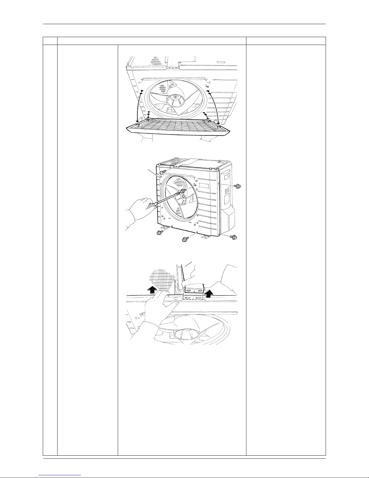
1. Remove the panels.
Take care not to cut your
finger by the fins of the
outdoor heat exchanger.
1
Remove the 4 screws
and lift the top panel.
2
Remove the 4 screws
and remove the
discharge grille.
Slide the discharge grille
upward and remove it.
Top panel
(R16425)
(R16426)
Discharge grille
(R16559)
Si00-876 Removal of Outer Panels
Removal Procedure 3
The discharge grille has 4
hooks.
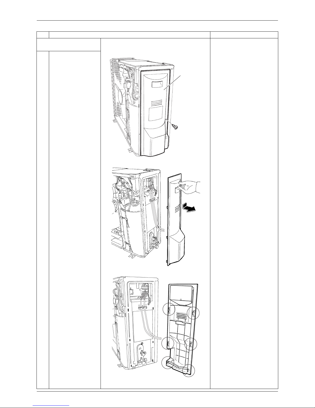
3
Remove the 6 screws
of the front panel.
4
Push the front panel
and lift the shield plate
to unfasten the hooks.
Step Procedure Points
(R2679)
Front panel
(R2680)
Shield plate
(R16560)
(1) Push the
front panel.
(2) Lift the shield
plate upwards.

Removal of Outer Panels Si00-876
4 Removal Procedure
5
Unfasten the left side
hooks, and then the
right side hook.
Remove the front panel.
Lift the front panel while
pushing the left side panel
inward.
Lift the front panel and
unfasten the right side hook.
When reassembling the
front panel, fit the right side
hook first.
Step Procedure Points
(R5249)
(R5250)
(R5251)
Si00-876 Removal of Outer Panels
Removal Procedure 5
2. Remove the stop valve
cover.
1
Remove the screw of
the stop valve cover.
2
Pull the stop valve
cover downward to
unfasten the hooks and
remove it.
The stop valve cover has 6
hooks.
Step Procedure Points
Stop valve cover
(R5252)
(R16679)
(R16680)
Removal of Outdoor Fan / Fan Motor Si00-876
6 Removal Procedure
2. Removal of Outdoor Fan / Fan Motor
Procedure Warning Be sure to wait for 10 minutes or more after turning off all power
supplies before disassembling work.
Step Procedure Points
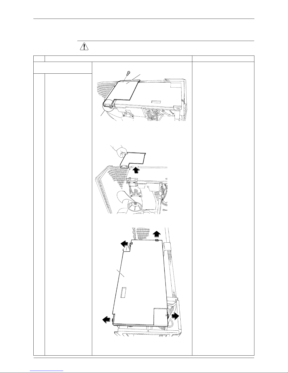
1. Remove the electrical box
cover.
Preparation
Remove the top panel and
the front panel according to
the “Removal of Outer
Panels”.
This procedure is not
necessary to remove the
outdoor fan only.
1
Remove the screw of
the shield plate.
2
Unfasten the 2 hooks
and remove the shield
plate.
3
Release the 4 hooks of
the electrical box cover
and remove it.
(R16429)
Shield plate
Claws
(R17063)
Electrical
box cover
(R2690)
Si00-876 Removal of Outdoor Fan / Fan Motor
Removal Procedure 7
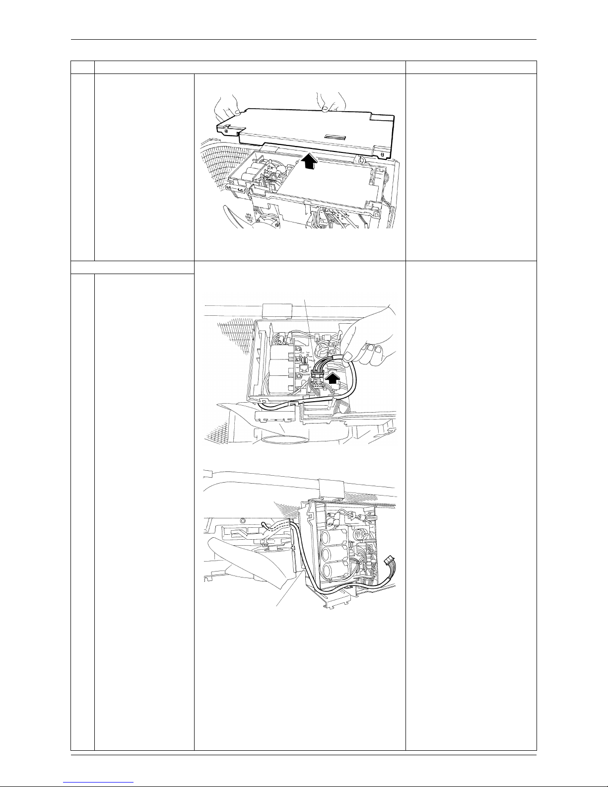
2. Remove the fan motor.
1
Disconnect the
connector for the fan
motor [S70].
2
The illustration shows
arrangement of the fan
motor lead wire.
Step Procedure Points
(R16431)
[S70]
(R2692)
Fan motor lead wire
(R2693)
 Loading...