

Daikin ATKS20CVMB, FTKS25CVMB, ATKS20DVMB, FTN20CVMB9, ATKS25DVMB Service Manual
...
Service
Manual
SiENBE04-512A
Inverter Pair
Wall Mounted Type
C-Series - D-Series

SiENBE04-512A
Inverter Pair
C-Series
D-Series
zCooling Only
Indoor Unit
FTKS20CVMB(9) ATKS20DVMB ATKS20CVMB(9) FTN20CVMB9
FTKS25CVMB(9)(8) ATKS25DVMB ATKS25CVMB(9) FTN25CVMB9
FTKS35CVMB(9)(8) ATKS35DVMB ATKS35CVMB(9) FTN35CVMB9
ATKS20DAVMB
ATKS25DAVMB
ATKS35DAVMB
Outdoor Unit
RKH20CVMB7 ARKH20CVMB7 ARKS20CVMB(9) RN20CVMB7
RKH25CVMB7 ARKH25CVMB7 ARKS25CVMB(9) RN25CVMB7
RKH35CVMB7 ARKH35CVMB7 ARKS35CVMB(9) RN35CVMB7
ARKS20C2VMB
ARKS25C2VMB
ARKS35C2VMB
zHeat Pump
Indoor Unit
FTXS20CVMB(9) ATXS20DVMB ATXS20CVMB(9) FTYN20CVMB9
FTXS25CVMB(9)(8) ATXS25DVMB ATXS25CVMB(9) FTYN25CVMB9
FTXS35CVMB(9)(8) ATXS35DVMB ATXS35CVMB(9) FTYN35CVMB9
ATXS20DAVMB
ATXS25DAVMB
ATXS35DAVMB
Outdoor Unit
RXH20CVMB7 ARXH20CVMB7 ARXS20CVMB(9) RYN20CVMB7
RXH25CVMB7 ARXH25CVMB7 ARXS25CVMB(9) RYN25CVMB7
RXH35CVMB7 ARXH35CVMB7 ARXS35CVMB(9) RYN35CVMB7
ARXS20C2VMB
ARXS25C2VMB
ARXS35C2VMB
Table of Contents i

SiENBE04-512A
1. Introduction .............................................................................................v
1.1 Safety Cautions........................................................................................v
Part 1 List of Functions ................................................................ 1
1. List of Functions......................................................................................2
1.1 High Grade Models ..................................................................................2
1.2 Standard Grade Models...........................................................................4
1.3 Non-lnverter Models.................................................................................7
Part 2 Specifications .................................................................... 9
1. Specifications........................................................................................10
1.1 Cooling Only...........................................................................................10
1.2 Heat Pump .............................................................................................16
Part 3 Printed Circuit Board Connector Wiring Diagram ........... 29
1. Printed Circuit Board Connector Wiring Diagram..................................30
1.1 Indoor Unit..............................................................................................30
1.2 Outdoor Unit / ARK(X)S-C......................................................................32
1.3 Outdoor Unit / RK(X)H-C, ARK(X)H-C, R(Y)N-C ...................................34
Part 4 Function and Control....................................................... 35
1. Main Functions......................................................................................36
1.1 Frequency Principle................................................................................36
1.2 Power-Airflow Dual Flaps, Wide-Angle Louvres and Auto-Swing..........38
1.3 Fan Speed Control for Indoor Units........................................................39
1.4 Programme Dry Function.......................................................................40
1.5 Automatic Operation...............................................................................41
1.6 NIGHT SET Mode..................................................................................42
1.7 INTELLIGENT EYE................................................................................43
1.8 HOME LEAVE Operation.......................................................................45
1.9 Inverter POWERFUL Operation.............................................................46
1.10 Other Functions......................................................................................47
2. Function of Thermistor..........................................................................48
2.1 Heat Pump Model...................................................................................48
2.2 Cooling Only Model................................................................................49
3. Control Specification.............................................................................50
3.1 Mode Hierarchy......................................................................................50
3.2 Frequency Control..................................................................................51
3.3 Controls at Mode Changing / Start-up....................................................53
3.4 Discharge Pipe Control ..........................................................................54
3.5 Input Current Control..............................................................................55
3.6 Freeze-up Protection Control.................................................................55
3.7 Heating Peak-cut Control.......................................................................56
3.8 Fan Control.............................................................................................56
3.9 Liquid Compression Protection Function 2.............................................56
3.10 Defrost Control.......................................................................................57
3.11 Electronic Expansion Valve Control.......................................................58
3.12 Malfunctions...........................................................................................61
3.13 Forced Operation Mode .........................................................................62
ii Table of Contents

SiENBE04-512A
3.14 Additional Function.................................................................................62
3.15 Facility Setting Jumper (cooling at low outdoor temperature)................63
Part 5 System Configuration....................................................... 65
1. System Configuration............................................................................66
2. Instruction..............................................................................................67
2.1 Safety precautions..................................................................................67
2.2 Names of parts.......................................................................................69
2.3 Preparation before Operation.................................................................72
2.4 AUTO · DRY · COOL · HEAT · FAN Operation......................................75
2.5 Adjusting the Air Flow Direction .............................................................77
2.6 POWERFUL Operation..........................................................................79
2.7 OUTDOOR UNIT SILENT Operation.....................................................80
2.8 HOME LEAVE Operation.......................................................................81
2.9 INTELLIGENT EYE Operation...............................................................83
2.10 TIMER Operation ...................................................................................85
2.11 Care and Cleaning .................................................................................87
2.12 Troubleshooting......................................................................................90
Part 6 Service Diagnosis............................................................. 95
1. Caution for Diagnosis............................................................................96
2. Problem Symptoms and Measures.......................................................97
3. Service Check Function........................................................................98
4. Troubleshooting ..................................................................................101
4.1 Error Codes and Description................................................................101
4.2 Indoor Unit PCB Abnormality ...............................................................102
4.3 Freeze-up Protection Control or High Pressure Control.......................103
4.4 Fan Motor (AC Motor) or Related Abnormality.....................................105
4.5 Thermistor or Related Abnormality (Indoor Unit)..................................106
4.6 Signal Transmission Error (between Indoor and Outdoor Unit) ...........107
4.7 OL Activation (Compressor Overload) .................................................108
4.8 Compressor Lock.................................................................................109
4.9 DC Fan Lock ........................................................................................110
4.10 Input Over Current Detection ...............................................................111
4.11 Four Way Valve Abnormality................................................................112
4.12 Discharge Pipe Temperature Control...................................................114
4.13 High Pressure Control in Cooling.........................................................115
4.14 Position Sensor Abnormality................................................................117
4.15 DC Voltage / Current Sensor Abnormality............................................118
4.16 Thermistor or Related Abnormality (Outdoor Unit)...............................119
4.17 Electrical Box Temperature Rise..........................................................121
4.18 Radiation Fin Temperature Rise ..........................................................123
4.19 Output Over Current Detection.............................................................125
4.20 Insufficient Gas.....................................................................................127
4.21 Over-voltage Detection.........................................................................129
5. Check..................................................................................................130
5.1 How to Check.......................................................................................130
Table of Contents iii

SiENBE04-512A
Part 7 Removal Procedure ........................................................ 139
1. Indoor Unit...........................................................................................140
1.1 Removal of Air Filter.............................................................................140
1.2 Removal of Front Grille ........................................................................143
1.3 Removal of Horizontal Blade and Vertical Blade..................................146
1.4 Removal of Switch Box, PC Board and Swing Motor...........................148
1.5 Removal of Heat Exchanger ................................................................154
1.6 Install of Drain Plug..............................................................................157
1.7 Removal of Fan Rotor and Fan Motor..................................................158
2. Outdoor Unit / ARK(X)S-C ..................................................................162
2.1 Removal of Panels and Fan Motor.......................................................162
2.2 Removal of Electrical Box ....................................................................169
2.3 Removal of Reactor and Partition Plate...............................................171
2.4 Removal of Sound Blanket...................................................................173
2.5 Removal of Four Way Valve.................................................................175
2.6 Removal of Compressor.......................................................................177
2.7 Removal of PCB...................................................................................179
3. Outdoor Unit / RK(X)H-C, ARK(X)H-C, R(Y)N-C ................................182
3.1 Removal of External Panels.................................................................182
3.2 Removal of Bell Mouth.........................................................................185
3.3 Removal of PCB...................................................................................186
3.4 Removal of Electrical Box ....................................................................194
3.5 Removal of Propeller Fan and Fan Motor............................................197
3.6 Removal of Compressor Sound Insulation Pad ...................................200
3.7 Removal of Compressor.......................................................................209
3.8 Removal of Four Way Valve.................................................................212
3.9 Removal of Electronic Expansion Valve...............................................215
Part 8 Others ............................................................................. 217
1. Others .................................................................................................218
1.1 Test Run from the Remote Control ......................................................218
1.2 Jumper Settings ...................................................................................219
Part 9 Appendix......................................................................... 221
1. Piping Diagrams..................................................................................222
1.1 Indoor Units..........................................................................................222
1.2 Outdoor Units.......................................................................................223
2. Wiring Diagrams..................................................................................229
2.1 Indoor Units..........................................................................................229
2.2 Outdoor Units.......................................................................................230
Index ............................................................................................. i
Drawings & Flow Charts ................................................................ v
iv Table of Contents
SiENBE04-512A Introduction
1. Introduction
1.1 Safety Cautions
Cautions and
Warnings
Be sure to read the following safety cautions before conducting repair work.
The caution items are classified into “ Warning” and “ Caution”. The “ Warning”
items are especially important since they can lead to death or serious injury if they are not
followed closely. The “ Caution” items can also lead to serious accidents under some
conditions if they are not followed. Therefore, be sure to observe all the safety caution items
described below.
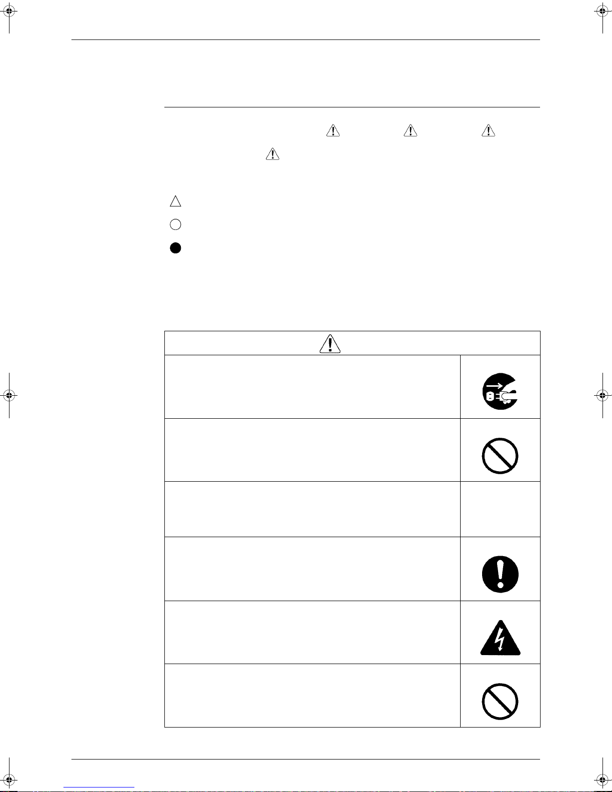
About the pictograms
This symbol indicates an item for which caution must be exercised.
The pictogram shows the item to which attention must be paid.
This symbol indicates a prohibited action.
The prohibited item or action is shown inside or near the symbol.
This symbol indicates an action that must be taken, or an instruction.
The instruction is shown inside or near the symbol.
After the repair work is complete, be sure to conduct a test operation to ensure that the
equipment operates normally, and explain the cautions for operating the product to the
customer.
1.1.1 Caution in Repair
Be sure to disconnect the power cable plug from the plug socket before
disassembling the equipment for a repair.
Working on the equipment that is connected to a power supply can cause an
electrical shook.
If it is necessary to supply power to the equipment to conduct the repair or
inspecting the circuits, do not touch any electrically charged sections of the
equipment.
If the refrigerant gas discharges during the repair work, do not touch the
discharging refrigerant gas.
The refrigerant gas can cause frostbite.
Warning
When disconnecting the suction or discharge pipe of the compressor at the
welded section, release the refrigerant gas completely at a well-ventilated
place first.
If there is a gas remaining inside the compressor, the refrig e ran t g as or
refrigerating machine oil discharges when the pipe is disconnected, and it can
cause injury.
If the refrigerant gas leaks during the repair work, ventilate the area. The
refrigerant gas can generate toxic gases when it contacts flames.
The step-up capacitor supplies high-voltage electricity to the electrical
components of the outdoor unit.
Be sure to discharge the capacitor completely before conducting repair work.
A charged capacitor can cause an electrical shock.
Do not start or stop the air conditioner operation by plugging or unplugging the
power cable plug.
Plugging or unplugging the power cable plug to operate the equipment can
cause an electrical shock or fire.
v
Introduction SiENBE04-512A
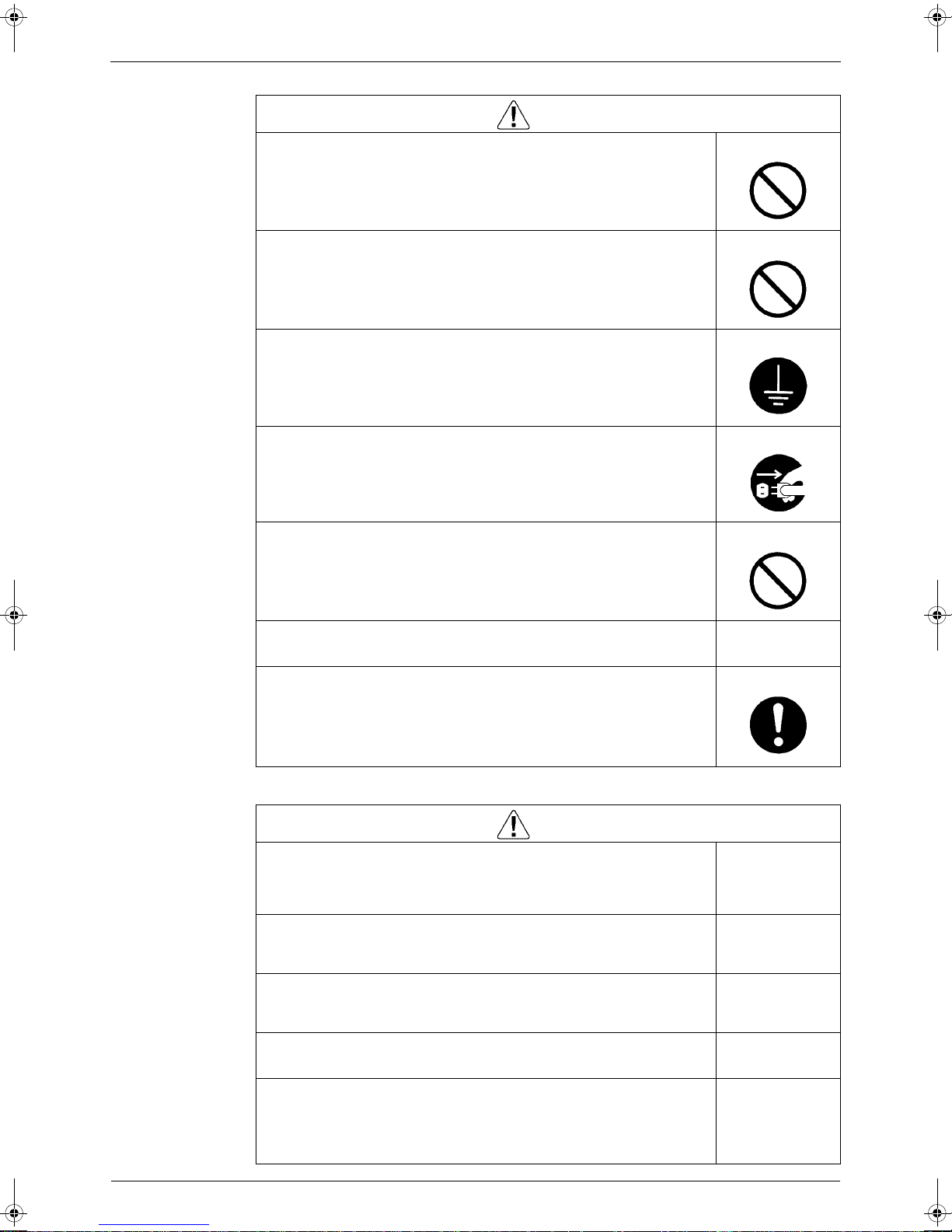
Warning
Do not repair the electrical components with wet hands.
Working on the equipment with wet hands can cause an electrical shock.
Do not clean the air conditioner by splashing water.
Washing the unit with water can cause an electrical shock.
Be sure to provide the grounding when repairing the equipment in a humid or
wet place, to avoid electrical shocks.
Be sure to turn off the power switch and unplug the power cable when cleaning
the equipment.
The internal fan rotates at a high speed, and cause injury.
Do not tilt the unit when removing it.
The water inside the unit can spill and wet the furniture and floor.
Be sure to check that the refrigerating cycle section has cooled down
sufficiently before conducting repair work.
Working on the unit when the refrigerating cycle section is hot can cause burns.
Use the welder in a well-ventilated place.
Using the welder in an enclosed room can cause oxygen deficiency.
1.1.2 Cautions Regarding Products after Repair
Warning
Be sure to use parts listed in the service parts list of the applicable model and
appropriate tools to conduct repair work. Never attempt to modify the
equipment.
The use of inappropriate parts or tools can cause an electrical shock,
excessive heat generation or fire.
When relocating the equipment, make sure that the new installation site has
sufficient strength to withstand the weight of the equipment.
If the installation site does not have sufficient strength and if the installation
work is not conducted securely, the equipment can fall and cause injury.
Be sure to install the product correctly by using the provided standard
installation frame.
Incorrect use of the installation frame and improper install ation can cause the
equipment to fall, resulting in injury.
Be sure to install the product securely in the installation frame mounted on a
window frame.
If the unit is not securely mounted, it can fall and cause injury.
Be sure to use an exclusive power circuit for the equipment, and follow the
technical standards related to the electrical equipment, the internal wiring
regulations and the instruction manual for installation when conducting
electrical work.
Insufficient power circuit capacity and improper electrical work can cause an
electrical shock or fire.
For integral units
only
For integral units
only
vi
SiENBE04-512A Introduction
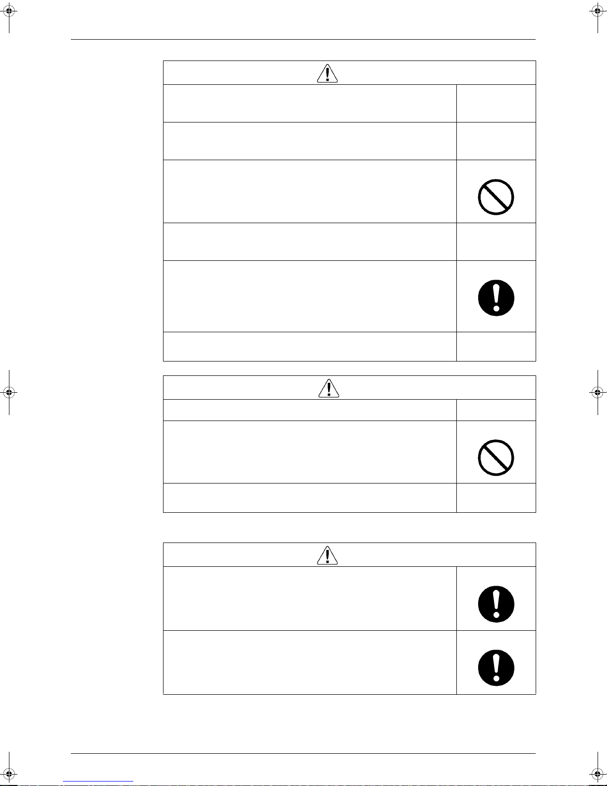
Warning
Be sure to use the specified cable to connect between the indoor and outdoor
units. Make the connections securely and route the cable properly so that there
is no force pulling the cable at the connection terminals.
Improper connections can cause excessive heat generation or fire.
When connecting the cable between the indoor and outdoor units, make sure
that the terminal cover does not lift off or dismount because of the cable.
If the cover is not mounted properly, the terminal connection section can cause
an electrical shock, excessive heat generation or fire.
Do not damage or modify the power cable.
Damaged or modified power cable can cause an electrical shock or fire.
Placing heavy items on the power cable, and heating or pulling the power cable
can damage the cable.
Do not mix air or gas other than the specified refrigerant (R-410A / R22) in the
refrigerant system.
If air enters the refrigerating system, an excessively high pressure results,
causing equipment damage and injury.
If the refrigerant gas leaks, be sure to locate the leak and repair it before
charging the refrigerant. After charging refrigerant, make sure that there is no
refrigerant leak.
If the leak cannot be located and the repair work mu st be stopped, be sure to
perform pump-down and close the service valve, to prevent the refrigerant gas
from leaking into the room. The refrigerant gas itself is harmless, but it can
generate toxic gases when it contacts flames, such as fan and other heaters,
stoves and ranges.
When replacing the coin battery in the remote controller, be sure to disposed
of the old battery to prevent children from swallowing it.
If a child swallows the coin battery, see a doctor immediately.
Installation of a leakage breaker is necessary in some cases depending on the
conditions of the installation site, to prevent electrical shocks.
Do not install the equipment in a place where there is a possibility of
combustible gas leaks.
If a combustible gas leaks and remains around the unit, it can cause a fire.
Be sure to install the packing and seal on the installation frame properly.
If the packing and seal are not installed properly, water can enter the room and
wet the furniture and floor.
1.1.3 Inspection after Repair
Check to make sure that the power cable plug is not dirty or loose, then insert
the plug into a power outlet all the way.
If the plug has dust or loose connection, it can cause an electrical shock or fire.
If the power cable and lead wires have scratches or deteriorated, be sure to
replace them.
Damaged cable and wires can cause an electrical shock, excessive heat
generation or fire.
Caution
For integral units
only
Warning
vii
Introduction SiENBE04-512A
Warning
Do not use a joined power cable or extension cable, or share the same power
outlet with other electrical appliances, since it can cause an electrical shock,
excessive heat generation or fire.
Caution
Check to see if the parts and wires are mounted and connected properly, and
if the connections at the soldered or crimped terminals are secure.
Improper installation and connections can cause excessive heat generation,
fire or an electrical shock.
If the installation platform or frame has corroded, replace it.
Corroded installation platform or frame can cause the unit to fall, resulting in
injury.
Check the grounding, and repair it if the equipment is not properly grounded.
Improper grounding can cause an electrical shock.
Be sure to measure the insulation resistance after the repair, and make sure
that the resistance is 1 Mohm or higher.
Faulty insulation can cause an electrical shock.
Be sure to check the drainage of the indoor unit after the repair.
Faulty drainage can cause the water to enter the room and wet the furniture
and floor.
1.1.4 Using Icons
Icons are used to attract the attention of the reader to specific information. The meaning of each
icon is described in the table below:
1.1.5 Using Icons List
Icon Type of
Note:
Caution
Warning
Information
Description
Note A “note” provides information that is not indispensable, but may
nevertheless be valuable to the reader, such as tips and tricks.
Caution A “caution” is used when there is danger that the reader, through
incorrect manipulation, may damage equipment, loose data, get
an unexpected result or has to restart (part of) a procedure.
Warning A “warning” is used when there is danger of personal injury.
Reference A “reference” guides the reader to other places in this binder or
in this manual, where he/she will find additional information on a
specific topic.
viii

SiENBE04-512A
Part 1
List of Functions
1. List of Functions......................................................................................2
1.1 High Grade Models ..................................................................................2
1.2 Standard Grade Models...........................................................................4
1.3 Non-lnverter Models.................................................................................7
List of Functions 1
List of Functions SiENBE04-512A
1. List of Functions
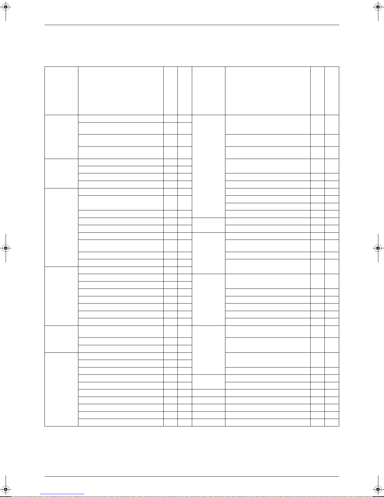
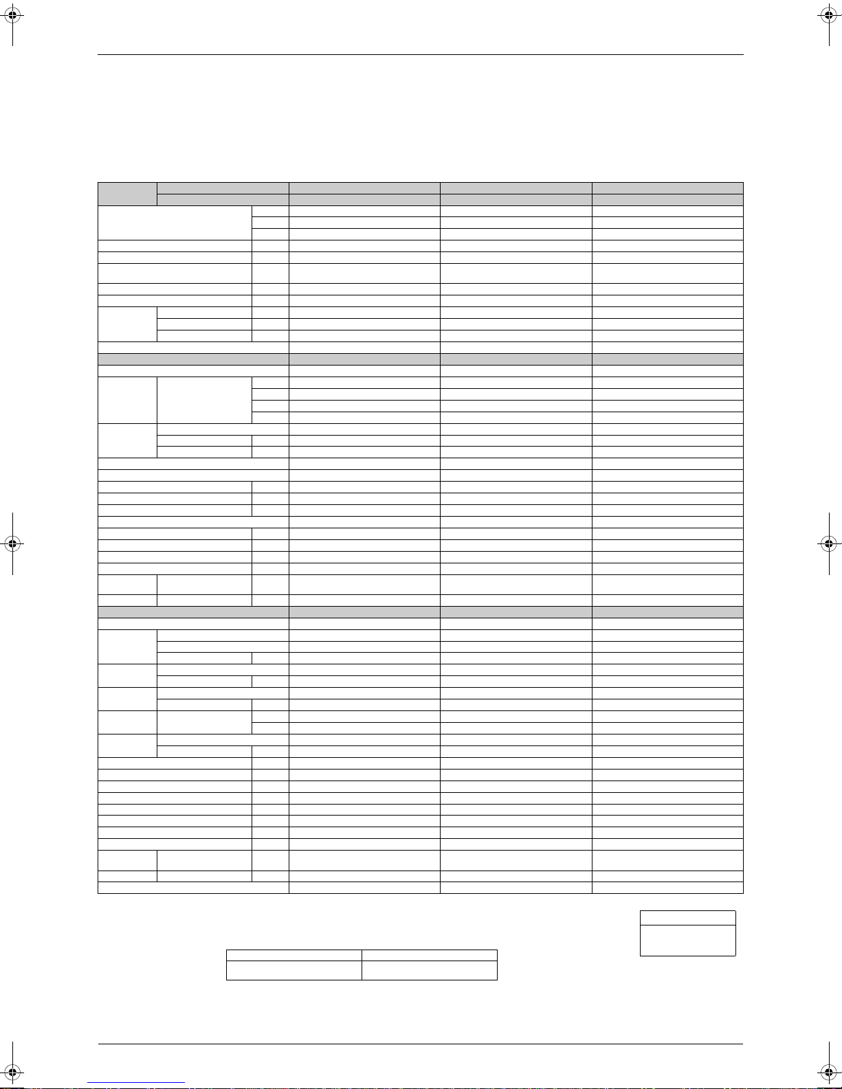
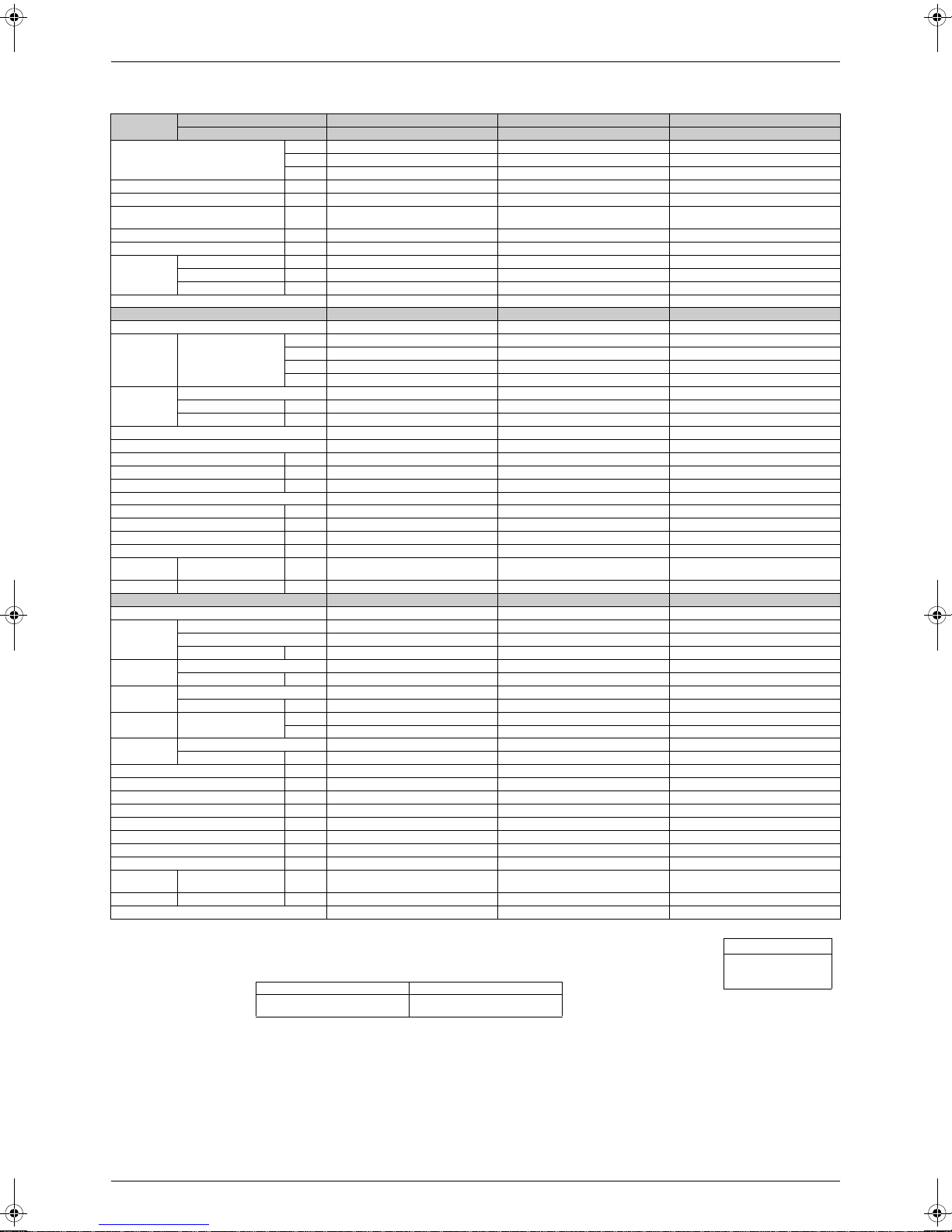
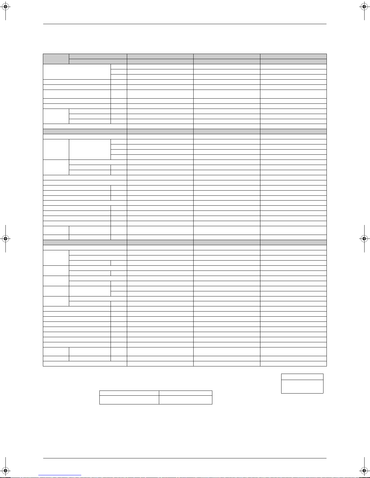
1.1 High Grade Models
Category Functions
Inverter (with Inverter Power Control) {{
Basic
Function
Compressor
Comfortable
Airflow
Comfort
Control
Operation
Lifestyle
Convenience
Operation Limit for Cooling (°CDB)
Operation Limit for Heating (°CWB) —
PAM Control {{
Oval Scroll Compressor — —
Swing Compressor {{
Rotary Compressor — — Mold Proof Air Filter {{
Reluctance DC Motor {{ Wipe-clean Flat Panel {{
Power-Airflow Flap — — Washable Grille — —
Power-Airflow Dual Flaps {{
Power-Airflow Diffuser — — Good-Sleep Cooling Operation — —
Wide-Angle Louvers {{
Vertical Auto-Swing (Up and Down) {{ Night Set Mode {{
Horizontal Auto-Swing (Right and Left) — —
3-D Airflow — — Self-Diagnosis (Digital, LED) Display
Comfort Airflow Mode — — Wiring Error Check — —
3-Step Airflow (H/P Only) — —
Auto Fan Speed {{
Indoor Unit Silent Operation {{
Night Quiet Mode (Automatic) — —
Outdoor Unit Silent Operation (Manual) {{ Flexible Voltage Correspondence {{
Intelligent Eye {{ High Ceiling Application — —
Quick Warming Function — { Chargeless 10m 10m
Hot-Start Function — { Either Side Drain (Right or Left) {{
Automatic Defrosting — { Power Selection — —
Automatic Operation — {
Programme Dry Function {{
Fan Only {{
New Powerful Operation (Non-Inverter) — —
Inverter Powerful Operation {{
Priority-Room Setting — —
Cooling / Heating Mode Lock — —
Home Leave Operation {{ Wired — —
ECONO Mode — —
Indoor Unit On/Off Switch {{
Signal Reception Indicator {{
Temperature Display — —
Another Room Operation — —
Note: { : Holding Functions
— : No Functions
H1
ATKS20-35DVMB
ARKS20-35CVMB(9)
–10
~46
Category Functions
ATXS20-35DVMB
ARXS20-35CVMB(9)
–10
~46
–15
~20
Health &
Clean
Timer
Worry Free
“Reliability &
Durability”
Flexibility
Remote
Control
Remote
Control
H
H2 :
ATKS20-35DVMB
Air Purifying Filter with Bacteriostatic,
Virustatic Functions
Photocatalytic Deodorizing Filter — —
Air Purifying Filter with Photocatalytic
Deodorizing Function
Titanium Apatite Photocatalytic
Air-Purifying Filter
Mold Proof Operation — —
Heating Dry Operation — —
24-Hour On/Off Timer {{
Auto-Restart (after Power Failure) {{
Anticorrosion Treatment of Outdoor
Heat Exchanger
Multi-Split / Split Type Compatible
Indoor Unit
5-Rooms Centralized Controller
(Option)
Remote Control Adapter
(Normal Open-Pulse Contact) (Option)
Remote Control Adapter
(Normal Open Contact) (Option)
DIII-NET Compatible (Adapter) (Option)
Infrared {{
1 :
Lower limit can be extended to –15°C by cutting
jumper. (facility use only)
Digital Only
——
{{
——
{
H2{H2
{{
{{
{{
{{
{{
{{
ARKS20-35CVMB(9)
ATXS20-35DVMB
ARXS20-35CVMB(9)
2 List of Functions
SiENBE04-512A List of Functions
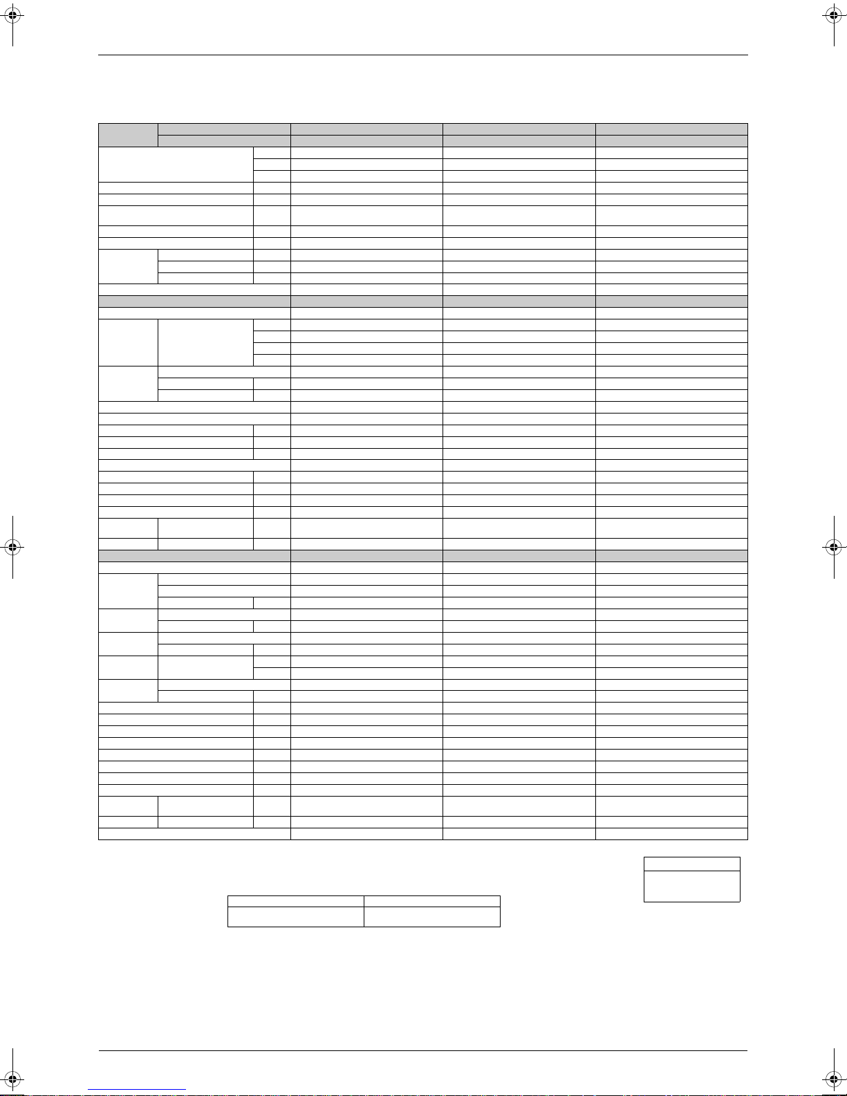
Category Functions
Inverter (with Inverter Power Control) {{
Basic
Function
Compressor
Comfortable
Airflow
Comfort
Control
Operation
Lifestyle
Convenience
Operation Limit for Cooling (°CDB)
Operation Limit for Heating (°CWB) —
PAM Control {{
Oval Scroll Compressor — —
Swing Compressor {{
Rotary Compressor — — Mold Proof Air Filter {{
Reluctance DC Motor {{ Wipe-clean Flat Panel {{
Power-Airflow Flap — — Washable Grille — —
Power-Airflow Dual Flaps {{
Power-Airflow Diffuser — — Good-Sleep Cooling Operation — —
Wide-Angle Louvers {{
Vertical Auto-Swing (Up and Down) {{ Night Set Mode {{
Horizontal Auto-Swing (Right and Left) — —
3-D Airflow — — Self-Diagnosis (Digital, LED) Display
Comfort Airflow Mode — — Wiring Error Check — —
3-Step Airflow (H/P Only) — —
Auto Fan Speed {{
Indoor Unit Silent Operation {{
Night Quiet Mode (Automatic) — —
Outdoor Unit Silent Operation (Manual) {{ Flexible Voltage Correspondence {{
Intelligent Eye {{ High Ceiling Application — —
Quick Warming Function — { Chargeless 10m 10m
Hot-Start Function — { Either Side Drain (Right or Left) {{
Automatic Defrosting — { Power Selection — —
Automatic Operation — {
Programme Dry Function {{
Fan Only {{
New Powerful Operation (Non-Inverter) — —
Inverter Powerful Operation {{
Priority-Room Setting — —
Cooling / Heating Mode Lock — —
Home Leave Operation {{ Wired — —
ECONO Mode — —
Indoor Unit On/Off Switch {{
Signal Reception Indicator {{
Temperature Display — —
Another Room Operation — —
Note: { : Holding Functions
— : No Functions
H1
–10
~46
ATKS20-35DAVMB
ARKS20-35C2VMB
Category Functions
ATXS20-35DAVMB
ARXS20-35C2VMB
–10
~46
–15
~20
Health &
Clean
Timer
Worry Free
“Reliability &
Durability”
Flexibility
Remote
Control
Remote
Control
H
H2 :
ATKS20-35DAVMB
Air Purifying Filter with Bacteriostatic,
Virustatic Functions
Photocatalytic Deodorizing Filter — —
Air Purifying Filter with Photocatalytic
Deodorizing Function
Titanium Apatite Photocatalytic
Air-Purifying Filter
Mold Proof Operation — —
Heating Dry Operation — —
24-Hour On/Off Timer {{
Auto-Restart (after Power Failure) {{
Anticorrosion Treatment of Outdoor
Heat Exchanger
Multi-Split / Split Type Compatible
Indoor Unit
5-Rooms Centralized Controller
(Option)
Remote Control Adapter
(Normal Open-Pulse Contact) (Option)
Remote Control Adapter
(Normal Open Contact) (Option)
DIII-NET Compatible (Adapter) (Option)
Infrared {{
1 :
Lower limit can be extended to –15°C by cutting
jumper. (facility use only)
Digital Only
——
{{
——
{
H2{H2
{{
{{
{{
{{
{{
{{
ARKS20-35C2VMB
ATXS20-35DAVMB
ARXS20-35C2VMB
List of Functions 3
List of Functions SiENBE04-512A
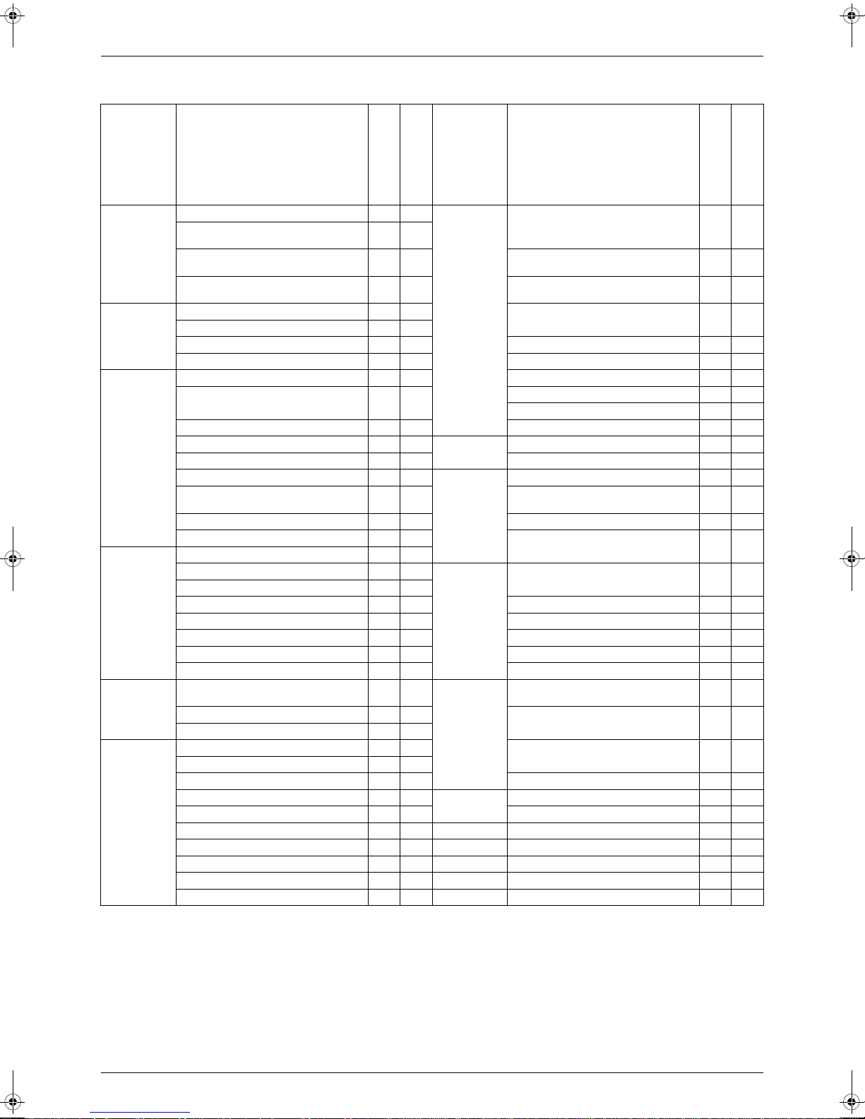
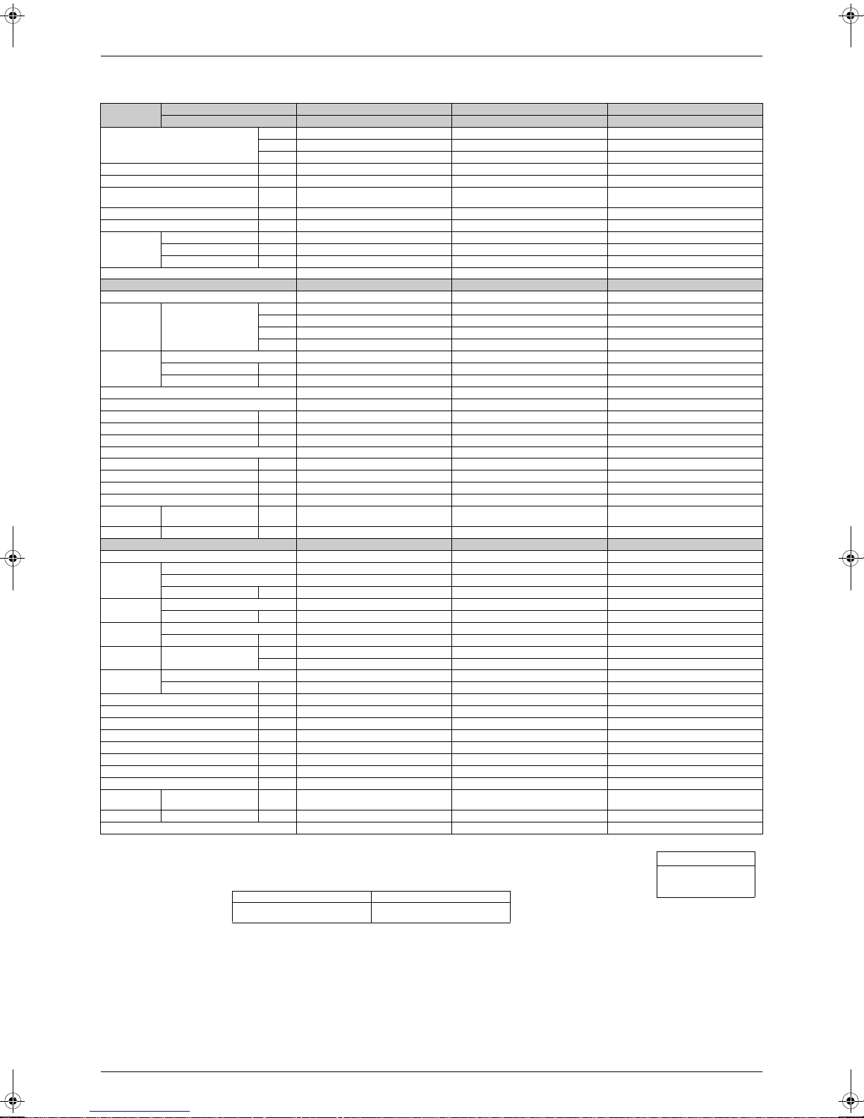
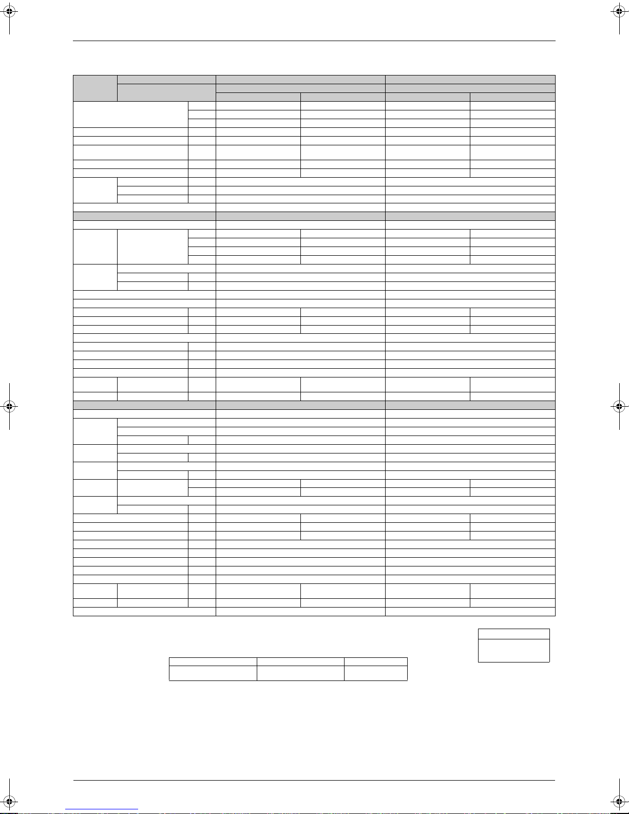
1.2 Standard Grade Models
Category Functions
Inverter (with Inverter Power Control) {{
Basic
Function
Compressor
Comfortable
Airflow
Comfort
Control
Operation
Lifestyle
Convenience
Operation Limit for Cooling (°CDB)
Operation Limit for Heating (°CDB) —
PAM Control — —
Oval Scroll Compressor — —
Swing Compressor — —
Rotary Compressor {{ Mold Proof Air Filter {{
Reluctance DC Motor — — Wipe-clean Flat Panel {{
Power-Airflow Flap — — Washable Grille — —
Power-Airflow Dual Flaps {{
Power-Airflow Diffuser — — Good-Sleep Cooling Operation — —
Wide-Angle Louvers {{
Vertical Auto-Swing (Up and Down) {{ Night Set Mode {{
Horizontal Auto-Swing (Right and Left) — —
3-D Airflow — — Self-Diagnosis (Digital, LED) Display
Comfort Airflow Mode — — Wiring Error Check — —
3-Step Airflow (H/P Only) — —
Auto Fan Speed {{
Indoor Unit Silent Operation {{
Night Quiet Mode (Automatic) — —
Outdoor Unit Silent Operation (Manual)
Intelligent Eye {{ High Ceiling Application — —
Quick Warming Function — { Chargeless 10m 10m
Hot-Start Function — { Either Side Drain (Right or Left) {{
Automatic Defrosting — { Power Selection — —
Automatic Operation — {
Programme Dry Function {{
Fan Only {{
New Powerful Operation (Non-Inverter) — —
Inverter Powerful Operation {{
Priority-Room Setting — —
Cooling / Heating Mode Lock — —
Home Leave Operation {{ Wired — —
ECONO Mode — —
Indoor Unit On/Off Switch {{
Signal Reception Indicator {{
Temperature Display — —
Another Room Operation — —
Note: { : Holding Functions
— : No Functions
Category Functions
FTKS20-35CVMB(9)(8)
RKH20-35CVMB7
FTXS20-35CVMB(9)(8)
RXH20-35CVMB7
10
~4610~46
–10
~20
Health &
Clean
Timer
Worry Free
“Reliability &
Durability”
—
H2—H2
Flexibility
Remote
Control
Remote
Control
Air Purifying Filter with Bacteriostatic,
Virustatic Functions
Photocatalytic Deodorizing Filter — —
Air Purifying Filter with Photocatalytic
Deodorizing Function
Titanium Apatite Photocatalytic
Air-Purifying Filter
Mold Proof Operation — —
Heating Dry Operation — —
24-Hour On/Off Timer {{
Auto-Restart (after Power Failure) {{
Anticorrosion Treatment of Outdoor
Heat Exchanger
Multi-Split / Split Type Compatible
Indoor Unit
Flexible Voltage Correspondence {{
5-Rooms Centralized Controller
(Option)
Remote Control Adapter
(Normal Open-Pulse Contact) (Option)
Remote Control Adapter
(Normal Open Contact) (Option)
DIII-NET Compatible (Adapter) (Option)
Infrared {{
H
1 :
Digital Only
H2 :
The button on the remote control does not work.
FTKS20-35CVMB(9)(8)
RKH25-35CVMB7
FTXS20-35CVMB(9)(8)
RXH20-35CVMB7
——
{{
——
{
H1{H1
{{
{{
{{
{{
{{
{{
4 List of Functions
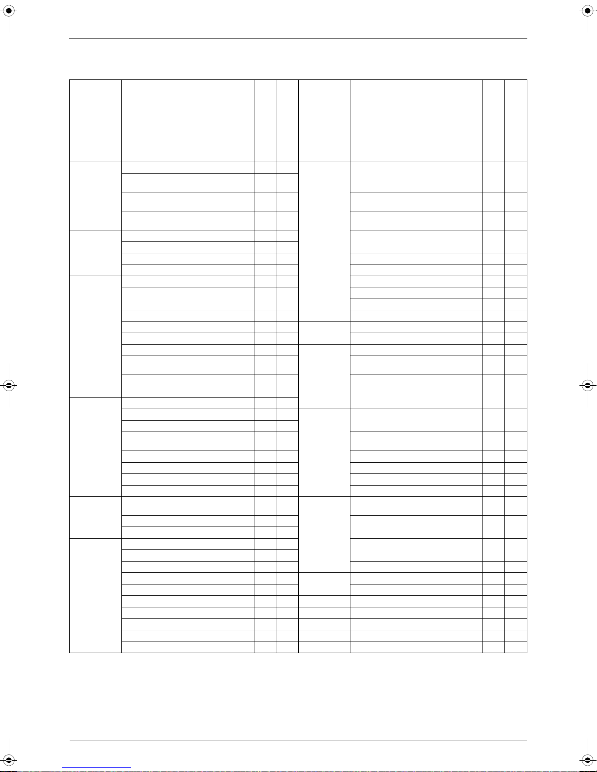
SiENBE04-512A List of Functions
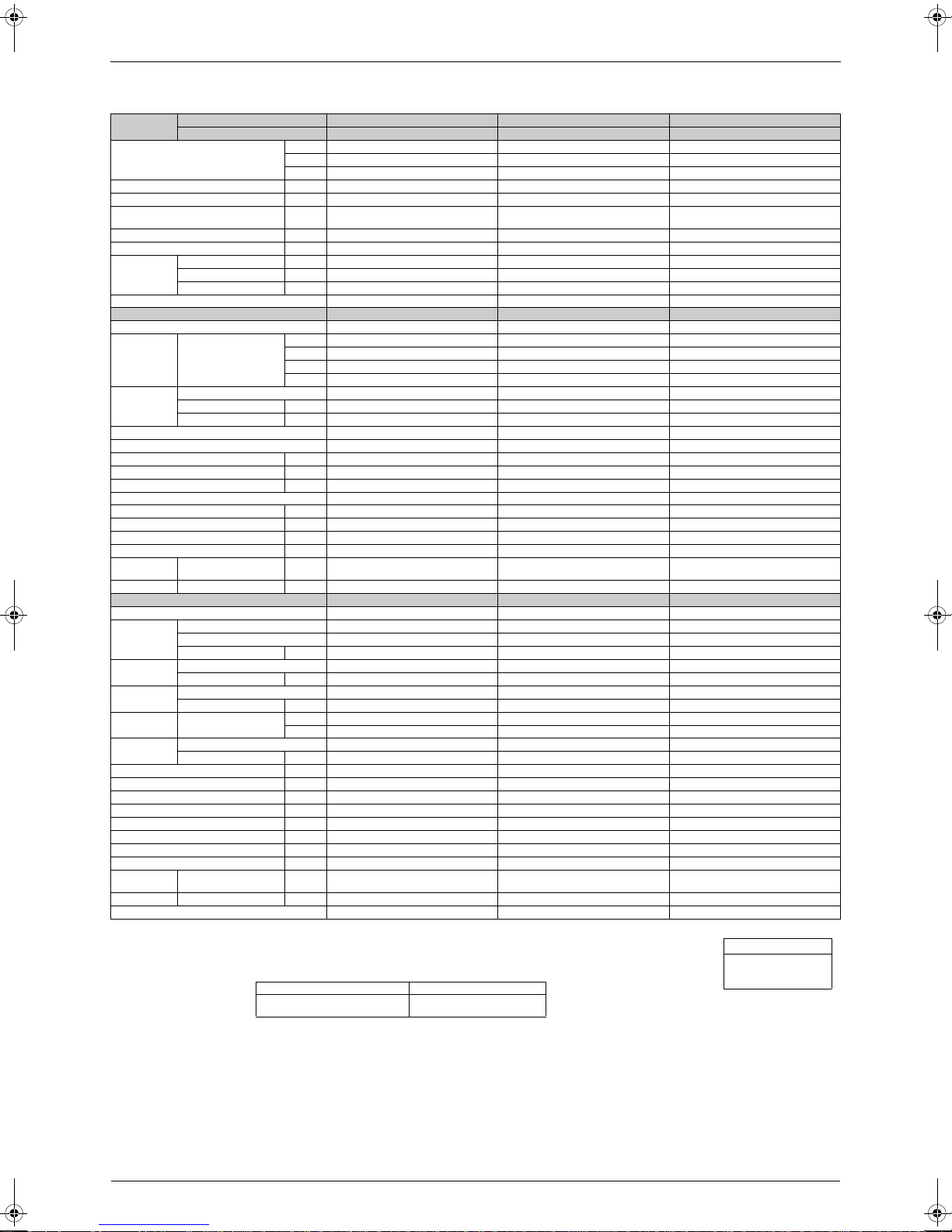
Category Functions
Inverter (with Inverter Power Control) {{
Basic
Function
Compressor
Comfortable
Airflow
Comfort
Control
Operation
Lifestyle
Convenience
Operation Limit for Cooling (°CDB)
Operation Limit for Heating (°CDB) —
PAM Control — —
Oval Scroll Compressor — —
Swing Compressor — —
Rotary Compressor {{ Mold Proof Air Filter {{
Reluctance DC Motor — — Wipe-clean Flat Panel — —
Power-Airflow Flap — —
Power-Airflow Dual Flaps {{
Power-Airflow Diffuser — — Good-Sleep Cooling Operation — —
Wide-Angle Louvers {{
Vertical Auto-Swing (Up and Down) {{ Night Set Mode {{
Horizontal Auto-Swing (Right and Left) — —
3-D Airflow — — Self-Diagnosis (Digital, LED) Display
Comfort Airflow Mode — — Wiring Error Check — —
3-Step Airflow (H/P Only) — —
Auto Fan Speed {{
Indoor Unit Silent Operation {{
Night Quiet Mode (Automatic) — —
Outdoor Unit Silent Operation (Manual)
Intelligent Eye {{ High Ceiling Application — —
Quick Warming Function — { Chargeless 10m 10m
Hot-Start Function — { Either Side Drain (Right or Left) {{
Automatic Defrosting — { Power Selection — —
Automatic Operation — {
Programme Dry Function {{
Fan Only {{
New Powerful Operation (Non-Inverter) — —
Inverter Powerful Operation {{
Priority-Room Setting — —
Cooling / Heating Mode Lock — —
Home Leave Operation {{ Wired — —
ECONO Mode — —
Indoor Unit On/Off Switch {{
Signal Reception Indicator {{
Temperature Display — —
Another Room Operation — —
Note: { : Holding Functions
— : No Functions
Category Functions
ATKS20-35CVMB(9)
ARKH20-35CVMB7
ATXS20-35CVMB(9)
ARXH20-35CVMB7
10
~4610~46
–10
~20
Health &
Clean
Timer
Worry Free
“Reliability &
Durability”
—
H2—H2
Flexibility
Remote
Control
Remote
Control
Air Purifying Filter with Bacteriostatic,
Virustatic Functions
Photocatalytic Deodorizing Filter — —
Air Purifying Filter with Photocatalytic
Deodorizing Function
Titanium Apatite Photocatalytic
Air-Purifying Filter
Washable Grille {{
Mold Proof Operation — —
Heating Dry Operation — —
Filter Cleaning Indicator — —
24-Hour On/Off Timer {{
Auto-Restart (after Power Failure) {{
Anticorrosion Treatment of Outdoor
Heat Exchanger
Multi-Split / Split Type Compatible
Indoor Unit
Flexible Voltage Correspondence {{
5-Rooms Centralized Controller
(Option)
Remote Control Adapter
(Normal Open-Pulse Contact) (Option)
Remote Control Adapter
(Normal Open Contact) (Option)
DIII-NET Compatible (Adapter) (Option)
Infrared {{
H
1 :
Digital Only
H2 :
The button on the remote control does not work.
ATKS20-35CVMB(9)
ARKH20-35CVMB7
ATXS20-35CVMB(9)
ARXH20-35CVMB7
——
{{
——
{
H1{H1
{{
{{
{{
{{
{{
{{
List of Functions 5
List of Functions SiENBE04-512A
Category Functions
Inverter (with Inverter Power Control) {{
Basic
Function
Compressor
Comfortable
Airflow
Comfort
Control
Operation
Lifestyle
Convenience
Operation Limit for Cooling (°CDB)
Operation Limit for Heating (°CDB) —
PAM Control — —
Oval Scroll Compressor — —
Swing Compressor — —
Rotary Compressor {{ Mold Proof Air Filter {{
Reluctance DC Motor — — Wipe-clean Flat Panel {{
Power-Airflow Flap — —
Power-Airflow Dual Flaps {{
Power-Airflow Diffuser — — Good-Sleep Cooling Operation — —
Wide-Angle Louvers {{
Vertical Auto-Swing (Up and Down) {{ Night Set Mode {{
Horizontal Auto-Swing (Right and Left) — —
3-D Airflow — — Self-Diagnosis (Digital, LED) Display
Comfort Airflow Mode — — Wiring Error Check — —
3-Step Airflow (H/P Only) — —
Auto Fan Speed {{
Indoor Unit Silent Operation {{
Night Quiet Mode (Automatic) — —
Outdoor Unit Silent Operation (Manual)
Intelligent Eye {{ High Ceiling Application — —
Quick Warming Function — { Chargeless 10m 10m
Hot-Start Function — { Either Side Drain (Right or Left) {{
Automatic Defrosting — { Power Selection — —
Automatic Operation — {
Programme Dry Function {{
Fan Only {{
New Powerful Operation (Non-Inverter) — —
Inverter Powerful Operation {{
Priority-Room Setting — —
Cooling / Heating Mode Lock — —
Home Leave Operation {{ Wired — —
ECONO Mode — —
Indoor Unit On/Off Switch {{
Signal Reception Indicator {{
Temperature Display — —
Another Room Operation — —
Note: { : Holding Functions
— : No Functions
ATKS20-35DVMB
ARKH20-35CVMB7
10
~4610~46
–10
~20
—
H2—H2
Category Functions
ATXS20-35DVMB
ARXH20-35CVMB7
Health &
Clean
Timer
Worry Free
“Reliability &
Durability”
Flexibility
Remote
Control
Remote
Control
H
1 :
H2 :
ATKS20-35DVMB
ARKH20-35CVMB7
ATXS20-35DVMB
ARXH20-35CVMB7
Air Purifying Filter with Bacteriostatic,
Virustatic Functions
Photocatalytic Deodorizing Filter — —
Air Purifying Filter with Photocatalytic
Deodorizing Function
Titanium Apatite Photocatalytic
Air-Purifying Filter
Washable Grille — —
Mold Proof Operation — —
Heating Dry Operation — —
Filter Cleaning Indicator — —
24-Hour On/Off Timer {{
Auto-Restart (after Power Failure) {{
Anticorrosion Treatment of Outdoor
Heat Exchanger
Multi-Split / Split Type Compatible
Indoor Unit
Flexible Voltage Correspondence {{
5-Rooms Centralized Controller
(Option)
Remote Control Adapter
(Normal Open-Pulse Contact) (Option)
Remote Control Adapter
(Normal Open Contact) (Option)
DIII-NET Compatible (Adapter) (Option)
Infrared {{
Digital Only
The button on the remote control does not work.
——
{{
——
{
H1{H1
{{
{{
{{
{{
{{
{{
6 List of Functions
SiENBE04-512A List of Functions
1.3 Non-lnverter Models
Category Functions
Inverter (with Inverter Power Control) — —
Basic
Function
Compressor
Comfortable
Airflow
Comfort
Control
Operation
Lifestyle
Convenience
Operation Limit for Cooling (°CDB)
Operation Limit for Heating (°CDB) —
PAM Control — —
Oval Scroll Compressor — — Mold Proof Air Filter {{
Swing Compressor — — Wipe-clean Flat Panel — —
Rotary Compressor {{ Washable Grille {{
Reluctance DC Motor — — Mold Proof Operation — —
Power-Airflow Flap — — Heating Dry Operation — —
Power-Airflow Dual Flaps {{ Good-Sleep Cooling Operation — —
Power-Airflow Diffuser — —
Wide-Angle Louvers {{ Night Set Mode {{
Vertical Auto-Swing (Up and Down) {{
Horizontal Auto-Swing (Right and Left) — — Self-Diagnosis (Digital, LED) Display
3-D Airflow — — Wiring Error Check — —
Comfort Airflow Mode — —
3-Step Airflow (H/P Only) — —
Auto Fan Speed {{
Indoor Unit Silent Operation — —
Night Quiet Mode (Automatic) — — Flexible Voltage Correspondence {{
Outdoor Unit Silent Operation (Manual) — — High Ceiling Application — —
Intelligent Eye — — Chargeless 10m 10m
Quick Warming Function — { Either Side Drain (Right or Left) {{
Hot-Start Function — { Power Selection — —
Automatic Defrosting — {
Automatic Operation — {
Programme Dry Function {{
Fan Only {{
New Powerful Operation (Non-Inverter) {{
Inverter Powerful Operation — —
Priority-Room Setting — —
Cooling / Heating Mode Lock — — Wired — —
Home Leave Operation — —
ECONO Mode — —
Indoor Unit On/Off Switch {{
Signal Reception Indicator {{
Temperature Display — —
Another Room Operation — —
Note: { : Holding Functions
— : No Functions
FTN20-35CVMB9
RN20-35CVMB7
FTYN20-35CVMB9
RYN20-35CVMB7
10
~4610~46
–10
~20
Category Functions
Air Purifying Filter with Bacteriostatic,
Virustatic Functions
Photocatalytic Deodorizing Filter — —
Air Purifying Filter with Photocatalytic
Deodorizing Function
Health &
Clean
Timer
Worry Free
“Reliability &
Durability”
Flexibility
Remote
Control
Remote
Control
Titanium Apatite Photocatalytic
Air-Purifying Filter
24-Hour On/Off Timer {{
Auto-Restart (after Power Failure) {{
Anticorrosion Treatment of Outdoor
Heat Exchanger
Multi-Split / Split Type Compatible
Indoor Unit
5-Rooms Centralized Controller
(Option)
Remote Control Adapter
(Normal Open-Pulse Contact) (Option)
Remote Control Adapter
(Normal Open Contact) (Option)
DIII-NET Compatible (Adapter) (Option)
Infrared {{
H
: Digital Only
FTN20-35CVMB9
RN25-35CVMB7
FTYN20-35CVMB9
RYN20-35CVMB7
——
{{
——
{
H{H
{{
——
{{
{{
{{
——
List of Functions 7

List of Functions SiENBE04-512A
8 List of Functions

SiENBE04-512A
Part 2
Specifications
1. Specifications........................................................................................10
1.1 Cooling Only...........................................................................................10
1.2 Heat Pump .............................................................................................16
Specifications 9
Specifications SiENBE04-512A
1. Specifications
1.1 Cooling Only
1.1.1 High Grade Models
50Hz 230V
Models
Capacity
Rated (Min.~Max.)
Moisture Removal L/h 0.9 1.2 1.9
Running Current (Rated) A 2.8 3.9 4.9
Power Consumption
Rated (Min.~Max.)
Power Factor % 79.6 79.3 94.3
COP (Rated) W/W 4.00 3.60 3.21
Piping
Connections
Heat Insulation Both Liquid and Gas Pipes Both Liquid and Gas Pipes Both Liquid and Gas Pipes
Indoor Units ATKS20DVMB ATKS25DVMB ATKS35DVMB
Front Panel Color White White White
Air Flow Rate
Fan
Air Direction Control Right, Left, Horizontal, Downward Right, Left, Horizontal, Downward Right, Left, Horizontal, Downward
Air Filter Removable / Washable / Mildew Proof Removable / Washable / Mildew Proof Removable / Washable / Mildew Proof
Running Current (Rated) A 0.18 0.18 0.18
Power Consumption (Rated) W 40 40 40
Power Factor % 96.6 96.6 96.6
Temperature Control Microcomputer Control Microcomputer Control Microcomputer Control
Dimensions (H×W×D) mm 273×784×195 273×784×195 273×784×195
Packaged Dimensions (H×W×D) mm 258×834×325 258×834×325 258×834×325
Weight kg 7.5 7.5 7.5
Gross Weight kg 11 11 11
Operation
Sound
Sound Power H dBA 56 56 57
Outdoor Units ARKS20CVMB(9) ARKS25CVMB(9) ARKS35CVMB(9)
Casing Color Ivory White Ivory White Ivory White
Compressor
Refrigerant
Oil
Refrigerant
Air Flow Rate
Fan
Running Current (Rated) A 2.62 3.72 4.72
Power Consumption (Rated) W 460 655 1,020
Power Factor % 76.3 76.6 94.0
Starting Current A 3.5 4.4 5.4
Dimensions (H×W×D) mm 550×765×285 550×765×285 550×765×285
Packaged Dimensions (H×W×D) mm 589×882×363 589×882×363 589×882×363
Weight kg 30 30 32
Gross Weight kg 35 35 38
Operation
Sound
Sound Power H dBA 59 61 62
Drawing No. 3D048480 3D048481 3D048482
Indoor Units ATKS20DVMB ATKS25DVMB ATKS35DVMB
Outdoor Units ARKS20CVMB(9) ARKS25CVMB(9) ARKS35CVMB(9)
Liquid mm φ 6.4 φ 6.4 φ 6.4
Gas mm φ 9.5 φ 9.5 φ 9.5
Drain mm φ18.0 φ18.0 φ 18.0
m³/min
(cfm)
Type Cross Flow Fan Cross Flow Fan Cross Flow Fan
Motor Output W 18 18 18
Speed Steps 5 Steps, Silent, Auto 5 Steps, Silent, Auto 5 Steps, Silent, Auto
H/M/L/SL dBA 38 / 32 / 25 / 22 38 / 32 / 25 / 22 39 / 33 / 26 / 23
Type Hermetically Sealed Swing Type Hermetically Sealed Swing Type Hermetically Sealed Swing Type
Model 1YC23NXD#A 1YC23NXD#A 1YC23NXD#A
Motor Output W 600 600 600
Type FVC50K FVC50K FVC50K
Charge L 0.375 0.375 0.375
Type R-410A R-410A R-410A
Charge kg 0.80 0.80 1.00
m³/min
(cfm)
Type Propeller Propeller Propeller
Motor Output W 31 31 35
H / L dBA 46 / 43 46 / 43 47 / 44
kW 2.0 (1.3~2.6) 2.5 (1.3~3.0) 3.4 (1.4~3.8)
Btu/h 6,800 (4,450~10,250) 8,550 (4,450~10,250) 11,600 (4,750~12,950)
kcal/h 1,720 (1,120~2,580) 2,150 (1,120~2,580) 2,920 (1,200~3,270)
W 500 (300~880) 695 (300~980) 1,060 (300~1,300)
H 7.7 (272) 7.7 (272) 7.7 (272)
M 5.9 (208) 5.9 (208) 6.0 (212)
L 4.2 (148) 4.2 (148) 4.4 (155)
SL 3.6 (127) 3.6 (127) 3.8 (134)
H 34 (1,201) 34 (1,201) 31.3 (1,105)
L 24.8 (876) 24.8 (876) 22.4 (791)
Note: MAX. interunit piping length: 20m
MAX. interunit height difference: 15m
Amount of additional charge of refrigerant 20g/m for piping length exceeding 10m
The data are based on the conditions shown in the table below.
Cooling Piping Length
Indoor ; 27°CDB/19°CWB
Outdoor ; 35°CDB/24°CWB
10 Specifications
7.5m
Conversion Formulae
kcal/h=kW×860
Btu/h=kW×3414
cfm=m³/min×35.3
SiENBE04-512A Specifications
50Hz 230V
Models
Capacity
Rated (Min.~Max.)
Moisture Removal L/h 0.9 1.2 1.9
Running Current (Rated) A 2.8 3.9 4.9
Power Consumption
Rated (Min.~Max.)
Power Factor % 79.6 79.3 94.3
COP (Rated) W/W 4.00 3.60 3.21
Piping
Connections
Heat Insulation Both Liquid and Gas Pipes Both Liquid and Gas Pipes Both Liquid and Gas Pipes
Indoor Units ATKS20DAVMB ATKS25DAVMB ATKS35DAVMB
Front Panel Color White White White
Air Flow Rate
Fan
Air Direction Control Right, Left, Horizontal, Downward Right, Left, Horizontal, Downward Right, Left, Horizontal, Downward
Air Filter Removable / Washable / Mildew Proof Removable / Washable / Mildew Proof Removable / Washable / Mildew Proof
Running Current (Rated) A 0.18 0.18 0.18
Power Consumption (Rated) W 40 40 40
Power Factor % 96.6 96.6 96.6
Temperature Control Microcomputer Control Microcomputer Control Microcomputer Control
Dimensions (H×W×D) mm 273×784×195 273×784×195 273×784×195
Packaged Dimensions (H×W×D) mm 258×834×325 258×834×325 258×834×325
Weight kg 7.5 7.5 7.5
Gross Weight kg 11 11 11
Operation
Sound
Sound Power H dBA 56 56 57
Outdoor Units ARKS20C2VMB ARKS25C2VMB ARKS35C2VMB
Casing Color Ivory White Ivory White Ivory White
Compressor
Refrigerant
Oil
Refrigerant
Air Flow Rate
Fan
Running Current (Rated) A 2.62 3.72 4.72
Power Consumption (Rated) W 460 655 1,020
Power Factor % 76.3 76.6 94.0
Starting Current A 3.5 4.4 5.4
Dimensions (H×W×D) mm 550×765×285 550×765×285 550×765×285
Packaged Dimensions (H×W×D) mm 589×882×363 589×882×363 589×882×363
Weight kg 30 30 32
Gross Weight kg 35 35 38
Operation
Sound
Sound Power H dBA 59 61 62
Drawing No. 3D050959 3D050961 3D050963
Indoor Units ATKS20DAVMB ATKS25DAVMB ATKS35DAVMB
Outdoor Units ARKS20C2VMB ARKS25C2VMB ARKS35C2VMB
Liquid mm φ 6.4 φ 6.4 φ 6.4
Gas mm φ 9.5 φ 9.5 φ 9.5
Drain mm φ18.0 φ18.0 φ 18.0
m³/min
(cfm)
Type Cross Flow Fan Cross Flow Fan Cross Flow Fan
Motor Output W 18 18 18
Speed Steps 5 Steps, Silent, Auto 5 Steps, Silent, Auto 5 Steps, Silent, Auto
H/M/L/SL dBA 38 / 32 / 25 / 22 38 / 32 / 25 / 22 39 / 33 / 26 / 23
Type Hermetically Sealed Swing Type Hermetically Sealed Swing Type Hermetically Sealed Swing Type
Model 1YC23NXD#A 1YC23NXD#A 1YC23NXD#A
Motor Output W 600 600 600
Type FVC50K FVC50K FVC50K
Charge L 0.375 0.375 0.375
Type R-410A R-410A R-410A
Charge kg 0.80 0.80 1.00
m³/min
(cfm)
Type Propeller Propeller Propeller
Motor Output W 31 31 35
H / L dBA 46 / 43 46 / 43 47 / 44
kW 2.0 (1.3~2.6) 2.5 (1.3~3.0) 3.4 (1.4~3.8)
Btu/h 6,800 (4,450~10,250) 8,550 (4,450~10,250) 11,600 (4,750~12,950)
kcal/h 1,720 (1,120~2,580) 2,150 (1,120~2,580) 2,920 (1,200~3,270)
W 500 (300~880) 695 (300~980) 1,060 (300~1,300)
H 7.7 (272) 7.7 (272) 7.7 (272)
M 5.9 (208) 5.9 (208) 6.0 (212)
L 4.2 (148) 4.2 (148) 4.4 (155)
SL 3.6 (127) 3.6 (127) 3.8 (134)
H 34 (1,201) 34 (1,201) 31.3 (1,105)
L 24.8 (876) 24.8 (876) 22.4 (791)
Note: MAX. interunit piping length: 20m
MAX. interunit height difference: 15m
Amount of additional charge of refrigerant 20g/m for piping length exceeding 10m
The data are based on the conditions shown in the table below.
Cooling Piping Length
Indoor ; 27°CDB/19°CWB
Outdoor ; 35°CDB/24°CWB
Specifications 11
7.5m
Conversion Formulae
kcal/h=kW×860
Btu/h=kW×3414
cfm=m³/min×35.3
Specifications SiENBE04-512A
1.1.2 Standard Grade Models
50Hz 230V
Models
Capacity
Rated (Min.~Max.)
Moisture Removal L/h 0.9 1.2 1.7
Running Current (Rated) A 3.3 3.7 4.9
Power Consumption
Rated (Min.~Max.)
Power Factor % 81.7 82.3 92.7
COP (Rated) W/W 3.23 3.21 3.01
Piping
Connections
Heat Insulation Both Liquid and Gas Pipes Both Liquid and Gas Pipes Both Liquid and Gas Pipes
Indoor Units FTKS20CVMB(9) FTKS25CVMB(9)(8) FTKS35CVMB(9)(8)
Front Panel Color White White White
Air Flow Rate
Fan
Air Direction Control Right, Left, Horizontal, Downward Right, Left, Horizontal, Downward Right, Left, Horizontal, Downward
Air Filter Removable / Washable / Mildew Proof Removable / Washable / Mildew Proof Removable / Washable / Mildew Proof
Running Current (Rated) A 0.18 0.18 0.18
Power Consumption (Rated) W 40 40 40
Power Factor % 96.6 96.6 96.6
Temperature Control Microcomputer Control Microcomputer Control Microcomputer Control
Dimensions (H×W×D) mm 273×784×195 273×784×195 273×784×195
Packaged Dimensions (H×W×D) mm 258×834×325 258×834×325 258×834×325
Weight kg 7.5 7.5 7.5
Gross Weight kg 11 11 11
Operation
Sound
Sound Power H dBA 56 56 57
Outdoor Units RKH20CVMB7 RKH25CVMB7 RKH35CVMB7
Casing Color Ivory White Ivory White Ivory White
Compressor
Refrigerant
Oil
Refrigerant
Air Flow Rate
Fan
Running Current (Rated) A 3.12 3.52 4.72
Power Consumption (Rated) W 580 660 1,005
Power Factor % 80.8 81.5 92.6
Starting Current A 3.3 3.7 4.9
Dimensions (H×W×D) mm 560×695×265 560×695×265 560×695×265
Packaged Dimensions (H×W×D) mm 599×824×337 599×824×337 599×824×337
Weight kg 31 31 33
Gross Weight kg 36 36 38
Operation
Sound
Sound Power H dBA 61 61 63
Drawing No. 3D048313 3D048314 3D048315
Indoor Units FTKS20CVMB(9) FTKS25CVMB(9)(8) FTKS35CVMB(9)(8)
Outdoor Units RKH20CVMB7 RKH25CVMB7 RKH35CVMB7
Liquid mm φ 6.4 φ 6.4 φ 6.4
Gas mm φ 9.5 φ 9.5 φ 9.5
Drain mm φ18.0 φ18.0 φ 18.0
m³/min
(cfm)
Type Cross Flow Fan Cross Flow Fan Cross Flow Fan
Motor Output W 18 18 18
Speed Steps 5 Steps, Silent, Auto 5 Steps, Silent, Auto 5 Steps, Silent, Auto
H/M/L/SL dBA 38 / 32 / 25 / 22 38 / 32 / 25 / 22 39 / 33 / 26 / 23
Type Hermetically Sealed Rotary Type Hermetically Sealed Rotary Type Hermetically Sealed Rotary Type
Model 5RS092XDH01 5RS092XDH01 5RS092XDH01
Motor Output W 650 650 650
Type RB68A RB68A RB68A
Charge L 0.320 0.320 0.320
Type R-410A R-410A R-410A
Charge kg 0.79 0.79 1.01
m³/min
(cfm)
Type Propeller Propeller Propeller
Motor Output W 25 25 25
H / L dBA 46 / — 46 / — 48 / —
kW 2.0 (1.3~2.6) 2.25 (1.3~3.0) 3.15 (1.4~3.8)
Btu/h 6,800 (4,450~8,850) 7,650 (4,450~10,250) 10,750 (4,750~12,950)
kcal/h 1,720 (1,120~2,240) 1,940 (1,120~2,580) 2,710 (1,200~3,270)
W 620 (430~945) 700 (430~1,200) 1,045 (460~1,425)
H 7.7 (272) 7.7 (272) 7.7 (272)
M 5.9 (208) 5.9 (208) 6.0 (212)
L 4.2 (148) 4.2 (148) 4.4 (155)
SL 3.6 (127) 3.6 (127) 3.8 (134)
H 29 (1,025) 29 (1,025) 27.5(972)
L — (—) — (—) — (—)
Note: MAX. interunit piping length: 15m
MAX. interunit height difference: 15m
Amount of additional charge of refrigerant 20g/m for piping length exceeding 10m
The data are based on the conditions shown in the table below.
Cooling Piping Length
Indoor ; 27°CDB/19°CWB
Outdoor ; 35°CDB/24°CWB
12 Specifications
7.5m
Conversion Formulae
kcal/h=kW×860
Btu/h=kW×3414
cfm=m³/min×35.3
SiENBE04-512A Specifications
50Hz 230V
Models
Capacity
Rated (Min.~Max.)
Moisture Removal L/h 0.9 1.2 1.7
Running Current (Rated) A 3.3 3.7 4.9
Power Consumption
Rated (Min.~Max.)
Power Factor % 81.7 82.3 92.7
COP (Rated) W/W 3.23 3.21 3.01
Piping
Connections
Heat Insulation Both Liquid and Gas Pipes Both Liquid and Gas Pipes Both Liquid and Gas Pipes
Indoor Units ATKS20CVMB(9) ATKS25CVMB(9) ATKS35CVMB(9)
Front Panel Color White White White
Air Flow Rate
Fan
Air Direction Control Right, Left, Horizontal, Downward Right, Left, Horizontal, Downward Right, Left, Horizontal, Downward
Air Filter Removable / Washable / Mildew Proof Removable / Washable / Mildew Proof Removable / Washable / Mildew Proof
Running Current (Rated) A 0.18 0.18 0.18
Power Consumption (Rated) W 40 40 40
Power Factor % 96.6 96.6 96.6
Temperature Control Microcomputer Control Microcomputer Control Microcomputer Control
Dimensions (H×W×D) mm 273×784×185 273×784×185 273×784×185
Packaged Dimensions (H×W×D) mm 258×834×325 258×834×325 258×834×325
Weight kg 7.5 7.5 7.5
Gross Weight kg 11 11 11
Operation
Sound
Sound Power H dBA 56 56 57
Outdoor Units ARKH20CVMB7 ARKH25CVMB7 ARKH35CVMB7
Casing Color Ivory White Ivory White Ivory White
Compressor
Refrigerant
Oil
Refrigerant
Air Flow Rate
Fan
Running Current (Rated) A 3.12 3.52 4.72
Power Consumption (Rated) W 580 660 1,005
Power Factor % 80.8 81.5 92,6
Starting Current A 3.3 3.7 4.9
Dimensions (H×W×D) mm 560×695×265 560×695×265 560×695×265
Packaged Dimensions (H×W×D) mm 599×824×337 599×824×337 599×824×337
Weight kg 31 31 33
Gross Weight kg 36 36 38
Operation
Sound
Sound Power H dBA 61 61 63
Drawing No. 3D048316 3D048317 3D048318
Indoor Units ATKS20CVMB(9) ATKS25CVMB(9) ATKS35CVMB(9)
Outdoor Units ARKH20CVMB7 ARKH25CVMB7 ARKH35CVMB7
Liquid mm φ 6.4 φ 6.4 φ 6.4
Gas mm φ 9.5 φ 9.5 φ 9.5
Drain mm φ18.0 φ18.0 φ 18.0
m³/min
(cfm)
Type Cross Flow Fan Cross Flow Fan Cross Flow Fan
Motor Output W 18 18 18
Speed Steps 5 Steps, Silent, Auto 5 Steps, Silent, Auto 5 Steps, Silent, Auto
H/M/L/SL dBA 38 / 32 / 25 / 22 38 / 32 / 25 / 22 39 / 33 / 26 / 23
Type Hermetically Sealed Rotary Type Hermetically Sealed Rotary Type Hermetically Sealed Rotary Type
Model 5RS092XDH01 5RS092XDH01 5RS092XDH01
Motor Output W 650 650 650
Type RB68A RB68A RB68A
Charge L 0.320 0.320 0.320
Type R-410A R-410A R-410A
Charge kg 0.79 0.79 1.01
m³/min
(cfm)
Type Propeller Propeller Propeller
Motor Output W 25 25 25
H / L dBA 46 / — 46 / — 48 / —
kW 2.0 (1.3~2.6) 2.25 (1.3~3.0) 3.15(1.4~3.8)
Btu/h 6,800 (4,450~8,850) 7,650 (4,450~10,250) 10,750 (4,750~12,950)
kcal/h 1,720 (1,120~2,240) 1,940 (1,120~2,580) 2,710 (1,200~3,270)
W 620 (430~945) 700 (430~1200) 1,045 (460~1,425)
H 7.7 (272) 7.7 (272) 7.7 (272)
M 5.9 (208) 5.9 (208) 6.1 (215)
L 4.2 (148) 4.2 (148) 4.4 (155)
SL 3.6 (127) 3.6 (127) 3.8 (134)
H 29 (1,025) 29 (1,025) 27.5 (972)
L — (—) — (—) — (—)
Note: MAX. interunit piping length: 15m
MAX. interunit height difference: 15m
Amount of additional charge of refrigerant 20g/m for piping length exceeding 10m
The data are based on the conditions shown in the table below.
Cooling Piping Length
Indoor ; 27°CDB/19°CWB
Outdoor ; 35°CDB/24°CWB
Specifications 13
7.5m
Conversion Formulae
kcal/h=kW×860
Btu/h=kW×3414
cfm=m³/min×35.3
Specifications SiENBE04-512A
50Hz 230V
Models
Capacity
Rated (Min.~Max.)
Moisture Removal L/h 0.9 1.2 1.7
Running Current (Rated) A 3.3 3.7 4.9
Power Consumption
Rated (Min.~Max.)
Power Factor % 81.7 82.3 92.7
COP (Rated) W/W 3.23 3.21 3.01
Piping
Connections
Heat Insulation Both Liquid and Gas Pipes Both Liquid and Gas Pipes Both Liquid and Gas Pipes
Indoor Units ATKS20DVMB ATKS25DVMB ATKS35DVMB
Front Panel Color White White White
Air Flow Rate
Fan
Air Direction Control Right, Left, Horizontal, Downward Right, Left, Horizontal, Downward Right, Left, Horizontal, Downward
Air Filter Removable / Washable / Mildew Proof Removable / Washable / Mildew Proof Removable / Washable / Mildew Proof
Running Current (Rated) A 0.18 0.18 0.18
Power Consumption (Rated) W 40 40 40
Power Factor % 96.6 96.6 96.6
Temperature Control Microcomputer Control Microcomputer Control Microcomputer Control
Dimensions (H×W×D) mm 273×784×195 273×784×195 273×784×195
Packaged Dimensions (H×W×D) mm 258×834×325 258×834×325 258×834×325
Weight kg 7.5 7.5 7.5
Gross Weight kg 11 11 11
Operation
Sound
Sound Power H dBA 56 56 57
Outdoor Units ARKH20CVMB7 ARKH25CVMB7 ARKH35CVMB7
Casing Color Ivory White Ivory White Ivory White
Compressor
Refrigerant
Oil
Refrigerant
Air Flow Rate
Fan
Running Current (Rated) A 3.12 3.52 4.72
Power Consumption (Rated) W 580 660 1005
Power Factor % 80.8 81.5 92.6
Starting Current A 3.3 3.7 4.9
Dimensions (H×W×D) mm 560×695×265 560×695×265 560×695×265
Packaged Dimensions (H×W×D) mm 599×824×337 599×824×337 599×824×337
Weight kg 31 31 33
Gross Weight kg 36 36 38
Operation
Sound
Sound Power H dBA 61 61 61
Drawing No. 3D048483A 3D048484A 3D048485A
Indoor Units ATKS20DVMB ATKS25DVMB ATKS35DVMB
Outdoor Units ARKH20CVMB7 ARKH25CVMB7 ARKH35CVMB7
Liquid mm φ 6.4 φ 6.4 φ 6.4
Gas mm φ 9.5 φ 9.5 φ 9.5
Drain mm φ18.0 φ18.0 φ 18.0
m³/min
(cfm)
Type Cross Flow Fan Cross Flow Fan Cross Flow Fan
Motor Output W 18 18 18
Speed Steps 5 Steps, Silent, Auto 5 Steps, Silent, Auto 5 Steps, Silent, Auto
H/M/L/SL dBA 38 / 32 / 25 / 22 38 / 32 / 25 / 22 39 / 33 / 26 / 23
Type Hermetically Sealed Rotary Type Hermetically Sealed Rotary Type Hermetically Sealed Rotary Type
Model 5RS092XDH01 5RS092XDH01 5RS092XDH01
Motor Output W 650 650 650
Type RB68A RB68A RB68A
Charge L 0.320 0.320 0.320
Type R-410A R-410A R-410A
Charge kg 0.79 0.79 1.01
m³/min
cfm
Type Propeller Propeller Propeller
Motor Output W 25 25 25
H/L dBA 46 / — 46 / — 48 / —
kW 2.0 (1.3~2.6) 2.25 (1.3~3.0) 3.15 (1.4~3.8)
Btu/h 6,800 (4,450~8,850) 7,650 (4,450~10,250) 10,750 (4,750~12,950)
kcal/h 1,720 (1,120~2,240) 1,940 (1,120~2,580) 2,710 (1,200~3,270)
W 620 (430~945) 700 (430~1,200) 1,045 (460~1,425)
H 7.7 (272) 7.7 (272) 7.7 (272)
M 5.9 (208) 5.9 (208) 6.0 (212)
L 4.2 (148) 4.2 (148) 4.4 (155)
SL 3.6 (127) 3.6 (127) 3.8 (134)
H 29 (1,025) 29 (1,025) 27.5 (972)
L———
Note: MAX. interunit piping length: 15m
MAX. interunit height difference: 10m
Amount of additional charge of refrigerant 20g/m for piping length exceeding 10m
The data are based on the conditions shown in the table below.
Cooling Piping Length
Indoor ; 27°CDB/19°CWB
Outdoor ; 35°CDB/24°CWB
14 Specifications
7.5m
Conversion Formulae
kcal/h=kW×860
Btu/h=kW×3414
cfm=m³/min×35.3
SiENBE04-512A Specifications
1.1.3 Non-lnverter Models
50Hz 230V
Models
Capacity
Rated (Min.~Max.)
Moisture Removal L/h 0.9 1.2 1.7
Running Current (Rated) A 3.3 3.7 4.9
Power Consumption
Rated (Min.~Max.)
Power Factor % 81.7 82.3 92.7
COP (Rated) W/W 3.23 3.21 3.01
Piping
Connections
Heat Insulation Both Liquid and Gas Pipes Both Liquid and Gas Pipes Both Liquid and Gas Pipes
Indoor Units FTN20CVMB9 FTN25CVMB9 FTN35CVMB9
Front Panel Color White White White
Air Flow Rate
Fan
Air Direction Control Right, Left, Horizontal, Downward Right, Left, Horizontal, Downward Right, Left, Horizontal, Downward
Air Filter Removable / Washable / Mildew Proof Removable / Washable / Mildew Proof Removable / Washable / Mildew Proof
Running Current (Rated) A 0.18 0.18 0.18
Power Consumption (Rated) W 40 40 40
Power Factor % 96.6 96.6 96.6
Temperature Control Microcomputer Control Microcomputer Control Microcomputer Control
Dimensions (H×W×D) mm 273×784×185 273×784×185 273×784×185
Packaged Dimensions (H×W×D) mm 258×834×325 258×834×325 258×834×325
Weight kg 7.5 7.5 7.5
Gross Weight kg 11 11 11
Operation
Sound
Sound Power H dBA 56 56 57
Outdoor Units RN20CVMB7 RN25CVMB7 RN35CVMB7
Casing Color Ivory White Ivory White Ivory White
Compressor
Refrigerant
Oil
Refrigerant
Air Flow Rate
Fan
Running Current (Rated) A 3.12 3.52 4.72
Power Consumption (Rated) W 580 660 1,005
Power Factor % 80.8 81.5 92.6
Starting Current A 3.3 3.7 4.9
Dimensions (H×W×D) mm 560×695×265 560×695×265 560×695×265
Packaged Dimensions (H×W×D) mm 599×824×337 599×824×337 599×824×337
Weight kg 31 31 33
Gross Weight kg 36 36 38
Operation
Sound
Sound Power H dBA 61 61 63
Drawing No. 3D048319 3D048320 3D048321
Indoor Units FTN20CVMB9 FTN25CVMB9 FTN35CVMB9
Outdoor Units RN20CVMB7 RN25CVMB7 RN35CVMB7
Liquid mm φ 6.4 φ 6.4 φ 6.4
Gas mm φ 9.5 φ 9.5 φ 9.5
Drain mm φ18.0 φ18.0 φ 18.0
m³/min
(cfm)
Type Cross Flow Fan Cross Flow Fan Cross Flow Fan
Motor Output W 18 18 18
Speed Steps 5 Steps, Auto 5 Steps, Auto 5 Steps, Auto
H/M/L/SL dBA 38 / 32 / 26 / — 38 / 32 / 26 / — 39 / 33 / 26 / —
Type Hermetically Sealed Rotary Type Hermetically Sealed Rotary Type Hermetically Sealed Rotary Type
Model 5RS092XDH01 5RS092XDH01 5RS092XDH01
Motor Output W 650 650 650
Type RB68A RB68A RB68A
Charge L 0.320 0.320 0.320
Type R-410A R-410A R-410A
Charge kg 0.79 0.79 1.01
m³/min
cfm
Type Propeller Propeller Propeller
Motor Output W 25 25 25
H/L dBA 46 / — 46 / — 48 / —
kW 2.0 2.25 3.15
Btu/h 6,800 7,650 10,750
kcal/h 1,720 1,940 2,710
W 620 700 1,045
H 7.7 (272) 7.7 (272) 7.7 (272)
M 5.9 (208) 5.9 (208) 6.1 (215)
L 4.2 (148) 4.2 (148) 4.4 (155)
SL———
H 29 (1,025) 29 (1,025) 27.5 (972)
L———
Note: MAX. interunit piping length: 15m
MAX. interunit height difference: 15m
Amount of additional charge of refrigerant 20g/m for piping length exceeding 10m
The data are based on the conditions shown in the table below.
Cooling Piping Length
Indoor ; 27°CDB/19°CWB
Outdoor ; 35°CDB/24°CWB
Specifications 15
7.5m
Conversion Formulae
kcal/h=kW×860
Btu/h=kW×3414
cfm=m³/min×35.3

Specifications SiENBE04-512A
1.2 Heat Pump
1.2.1 High Grade Models
50Hz 230V
Models
Capacity
Rated (Min.~Max.)
Moisture Removal L/h 0.9 — 1.2 —
Running Current (Rated) A 2.8 3.5 3.9 4.4
Power Consumption
Rated (Min.~Max.)
Power Factor % 79.6 82.1 79.3 93.7
COP (Rated) W/W 4.00 4.00 3.60 3.64
Piping
Connections
Heat Insulation Both Liquid and Gas Pipes Both Liquid and Gas Pipes
Indoor Units ATXS20DVMB ATXS25DVMB
Front Panel Color White White
Air Flow Rate
Fan
Air Direction Control Right, Left, Horizontal, Downward Right, Left, Horizontal, Downward
Air Filter Removable / Washable / Mildew Proof Removable / Washable / Mildew Proof
Running Current (Rated) A 0.18 0.18 0.18 0.18
Power Consumption (Rated) W 40 40 40 40
Power Factor % 96.6 96.6 96.6 96.6
Temperature Control Microcomputer Control Microcomputer Control
Dimensions (H×W×D) mm 273×784×195 273×784×195
Packaged Dimensions (H×W×D) mm 258×834×325 258×834×325
Weight kg 7.5 7.5
Gross Weight kg 11 11
Operation
Sound
Sound Power H dBA 56 56 56 56
Outdoor Units ARXS20CVMB(9) ARXS25CVMB(9)
Casing Color Ivory White Ivory White
Compressor
Refrigerant
Oil
Refrigerant
Air Flow Rate m³/min (cfm)
Fan
Running Current (Rated) A 2.62 3.32 3.72 4.22
Power Consumption (Rated) W 460 635 655 895
Power Factor % 76.3 83.2 76.6 92.2
Starting Current A 3.5 4.4
Dimensions (H×W×D) mm 550×765×285 550×765×285
Packaged Dimensions (H×W×D) mm 589×882×363 589×882×363
Weight kg 30 30
Gross Weight kg 35 35
Operation
Sound
Sound Power H dBA 61 62 61 62
Drawing No. 3D048474 3D048475
Indoor Units ATXS20DVMB ATXS25DVMB
Outdoor Units
kW 2.0 (1.3~2.6) 2.7 (1.3~4.0) 2.5 (1.3~3.0) 3.4 (1.3~4.5)
Btu/h 6,800 (4,450~10,250) 9,200 (4,450~15,350) 8,550 (4,450~10,250) 11,600 (4,450~15,350)
kcal/h 1,720 (1,120~2,580) 2,320 (1,120~3,870) 2,150 (1,120~2,580) 2,920 (1,120~3,870)
W 500 (300~880) 675 (290~1,300) 695 (300~980) 935 (290~1,460)
Liquid mm φ 6.4 φ 6.4
Gas mm φ 9.5 φ 9.5
Drain mm φ18.0 φ18.0
H 7.7 (272) 7.8 (275) 7.7 (272) 7.8 (275)
m³/min
(cfm)
Type Cross Flow Fan Cross Flow Fan
Motor Output W 18 18
Speed Steps 5 Steps, Silent, Auto 5 Steps, Silent, Auto
H/M/L/SL dBA 38 / 32 / 25 / 22 38 / 33 / 28 / 25 38 / 32 / 25 / 22 38 / 33 / 28 / 25
Type Hermetically Sealed Swing Type Hermetically Sealed Swing Type
Model 1YC23NXD#A 1YC23NXD#A
Motor Output W 600 600
Type FVC50K FVC50K
Charge L 0.375 0.375
Type R-410A R-410A
Charge kg 0.80 0.80
Type Propeller Propeller
Motor Output W 31 31
H/L dBA 46 / 43 47 / 44 46 / 43 47 / 44
M 5.9 (208) 6.5 (230) 5.9 (208) 6.5 (230)
L 4.2 (148) 5.3 (187) 4.2 (148) 5.3 (187)
SL 3.6 (127) 4.6 (162) 3.6 (127) 4.6 (162)
H 34 (1,201) 30.6 (1,080) 34 (1,201) 30.6 (1,080)
L 24.8 (876) 24.7 (872) 24.8 (876) 24.7 (872)
ARXS20CVMB(9) ARXS25CVMB(9)
Cooling Heating Cooling Heating
Note: MAX. interunit piping length: 20m
MAX. interunit height difference: 15m
Amount of additional charge of refrigerant 20g/m for piping length exceeding 10m
The data are based on the conditions shown in the table below.
Cooling Heating Piping Length
Indoor ; 27°CDB/19°CWB
Outdoor ; 35°CDB/24°CWB
16 Specifications
Indoor ; 20°CDB
Outdoor ; 7°CDB/6°CWB
7.5m
Conversion Formulae
kcal/h=kW×860
Btu/h=kW×3414
cfm=m³/min×35.3

SiENBE04-512A Specifications
50Hz 230V
Models
Capacity
Rated (Min.~Max.)
Moisture Removal L/h 1.9 —
Running Current (Rated) A 4.9 5.4
Power Consumption
Rated (Min.~Max.)
Power Factor % 94.3 95.4
COP (Rated) W/W 3.21 3.42
Piping
Connections
Heat Insulation Both Liquid and Gas Pipes
Indoor Units ATXS35DVMB
Front Panel Color White
Air Flow Rate
Fan
Air Direction Control Right, Left, Horizontal, Downward
Air Filter Removable / Washable / Mildew Proof
Running Current (Rated) A 0.18 0.18
Power Consumption (Rated) W 40 40
Power Factor % 96.6 96.6
Temperature Control Microcomputer Control
Dimensions (H×W×D) mm 273×784×195
Packaged Dimensions (H×W×D) mm 258×834×325
Weight kg 7.5
Gross Weight kg 11
Operation
Sound
Sound Power H dBA 57 57
Outdoor Units ARXS35CVMB(9)
Casing Color Ivory White
Compressor
Refrigerant
Oil
Refrigerant
Air Flow Rate m³/min (cfm)
Fan
Running Current (Rated) A 4.72 5.22
Power Consumption (Rated) W 1,020 1,130
Power Factor % 94.0 94.1
Starting Current A 5.4
Dimensions (H×W×D) mm 550×765×285
Packaged Dimensions (H×W×D) mm 589×882×363
Weight kg 32
Gross Weight kg 38
Operation
Sound
Sound Power H dBA 62 63
Drawing No. 3D048476
Indoor Units ATXS35DVMB
Outdoor Units
kW 3.4 (1.4~3.8) 4.0 (1.4~5.0)
Btu/h 11,600 (4,750~12,950) 13,650 (4,750~17,050)
kcal/h 2,920 (1,200~3,270) 3,440 (1,200~4,300)
W 1,060 (300~1,300) 1,170 (310~1,590)
Liquid mm φ 6.4
Gas mm φ 9.5
Drain mm φ18.0
H 7.7 (272) 8.1 (286)
m³/min
(cfm)
Type Cross Flow Fan
Motor Output W 18
Speed Steps 5 Steps, Silent, Auto
H/M/L/SL dBA 39 / 33 / 26 / 23 39 / 34 / 29 / 26
Type Hermetically Sealed Swing Type
Model 1YC23NXD#A
Motor Output W 600
Type FVC50K
Charge L 0.375
Type R-410A
Charge kg 1.00
Type Propeller
Motor Output W 35
H/L dBA 47 / 44 48 / 45
M 6.0 (212) 6.7 (237)
L 4.4 (155) 5.3 (187)
SL 3.8 (134) 4.6 (162)
H 31.3 (1,105) 28.1 (992)
L 22.4 (791) 22.4 (791)
Cooling Heating
ARXS35CVMB(9)
Note: MAX. interunit piping length: 20m
MAX. interunit height difference: 15m
Amount of additional charge of refrigerant 20g/m for piping length exceeding 10m
The data are based on the conditions shown in the table below.
Cooling Heating Piping Length
Indoor ; 27°CDB/19°CWB
Outdoor ; 35°CDB/24°CWB
Specifications 17
Indoor ; 20°CDB
Outdoor ; 7°CDB/6°CWB
7.5m
Conversion Formulae
kcal/h=kW×860
Btu/h=kW×3414
cfm=m³/min×35.3
Specifications SiENBE04-512A
50Hz 230V
Models
Capacity
Rated (Min.~Max.)
Moisture Removal L/h 0.9 — 1.2 —
Running Current (Rated) A 2.8 3.5 3.9 4.4
Power Consumption
Rated (Min.~Max.)
Power Factor % 79.6 82.1 79.3 93.7
COP (Rated) W/W 4.00 4.00 3.60 3.64
Piping
Connections
Heat Insulation Both Liquid and Gas Pipes Both Liquid and Gas Pipes
Indoor Units ATXS20DAVMB ATXS25DAVMB
Front Panel Color White White
Air Flow Rate
Fan
Air Direction Control Right, Left, Horizontal, Downward Right, Left, Horizontal, Downward
Air Filter Removable / Washable / Mildew Proof Removable / Washable / Mildew Proof
Running Current (Rated) A 0.18 0.18 0.18 0.18
Power Consumption (Rated) W 40 40 40 40
Power Factor % 96.6 96.6 96.6 96.6
Temperature Control Microcomputer Control Microcomputer Control
Dimensions (H×W×D) mm 273×784×195 273×784×195
Packaged Dimensions (H×W×D) mm 258×834×325 258×834×325
Weight kg 7.5 7.5
Gross Weight kg 11 11
Operation
Sound
Sound Power H dBA 56 56 56 56
Outdoor Units ARXS20C2VMB ARXS25C2VMB
Casing Color Ivory White Ivory White
Compressor
Refrigerant
Oil
Refrigerant
Air Flow Rate m³/min (cfm)
Fan
Running Current (Rated) A 2.62 3.32 3.72 4.22
Power Consumption (Rated) W 460 635 655 895
Power Factor % 76.3 83.2 76.6 92.2
Starting Current A 3.5 4.4
Dimensions (H×W×D) mm 550×765×285 550×765×285
Packaged Dimensions (H×W×D) mm 589×882×363 589×882×363
Weight kg 30 30
Gross Weight kg 35 35
Operation
Sound
Sound Power H dBA 61 62 61 62
Drawing No. 3D050953 3D050955
Indoor Units ATXS20DAVMB ATXS25DAVMB
Outdoor Units
kW 2.0 (1.3~2.6) 2.7 (1.3~4.0) 2.5 (1.3~3.0) 3.4 (1.3~4.5)
Btu/h 6,800 (4,450~10,250) 9,200 (4,450~15,350) 8,550 (4,450~10,250) 11,600 (4,450~15,350)
kcal/h 1,720 (1,120~2,580) 2,320 (1,120~3,870) 2,150 (1,120~2,580) 2,920 (1,120~3,870)
W 500 (300~880) 675 (290~1,300) 695 (300~980) 935 (290~1,460)
Liquid mm φ 6.4 φ 6.4
Gas mm φ 9.5 φ 9.5
Drain mm φ18.0 φ18.0
H 7.7 (272) 7.8 (275) 7.7 (272) 7.8 (275)
m³/min
(cfm)
Type Cross Flow Fan Cross Flow Fan
Motor Output W 18 18
Speed Steps 5 Steps, Silent, Auto 5 Steps, Silent, Auto
H/M/L/SL dBA 38 / 32 / 25 / 22 38 / 33 / 28 / 25 38 / 32 / 25 / 22 38 / 33 / 28 / 25
Type Hermetically Sealed Swing Type Hermetically Sealed Swing Type
Model 1YC23NXD#A 1YC23NXD#A
Motor Output W 600 600
Type FVC50K FVC50K
Charge L 0.375 0.375
Type R-410A R-410A
Charge kg 0.80 0.80
Type Propeller Propeller
Motor Output W 31 31
H/L dBA 46 / 43 47 / 44 46 / 43 47 / 44
M 5.9 (208) 6.5 (230) 5.9 (208) 6.5 (230)
L 4.2 (148) 5.3 (187) 4.2 (148) 5.3 (187)
SL 3.6 (127) 4.6 (162) 3.6 (127) 4.6 (162)
H 34 (1,201) 30.6 (1,080) 34 (1,201) 30.6 (1,080)
L 24.8 (876) 24.7 (872) 24.8 (876) 24.7 (872)
ARXS20C2VMB ARXS25C2VMB
Cooling Heating Cooling Heating
Note: MAX. interunit piping length: 20m
MAX. interunit height difference: 15m
Amount of additional charge of refrigerant 20g/m for piping length exceeding 10m
The data are based on the conditions shown in the table below.
Cooling Heating Piping Length
Indoor ; 27°CDB/19°CWB
Outdoor ; 35°CDB/24°CWB
18 Specifications
Indoor ; 20°CDB
Outdoor ; 7°CDB/6°CWB
7.5m
Conversion Formulae
kcal/h=kW×860
Btu/h=kW×3414
cfm=m³/min×35.3
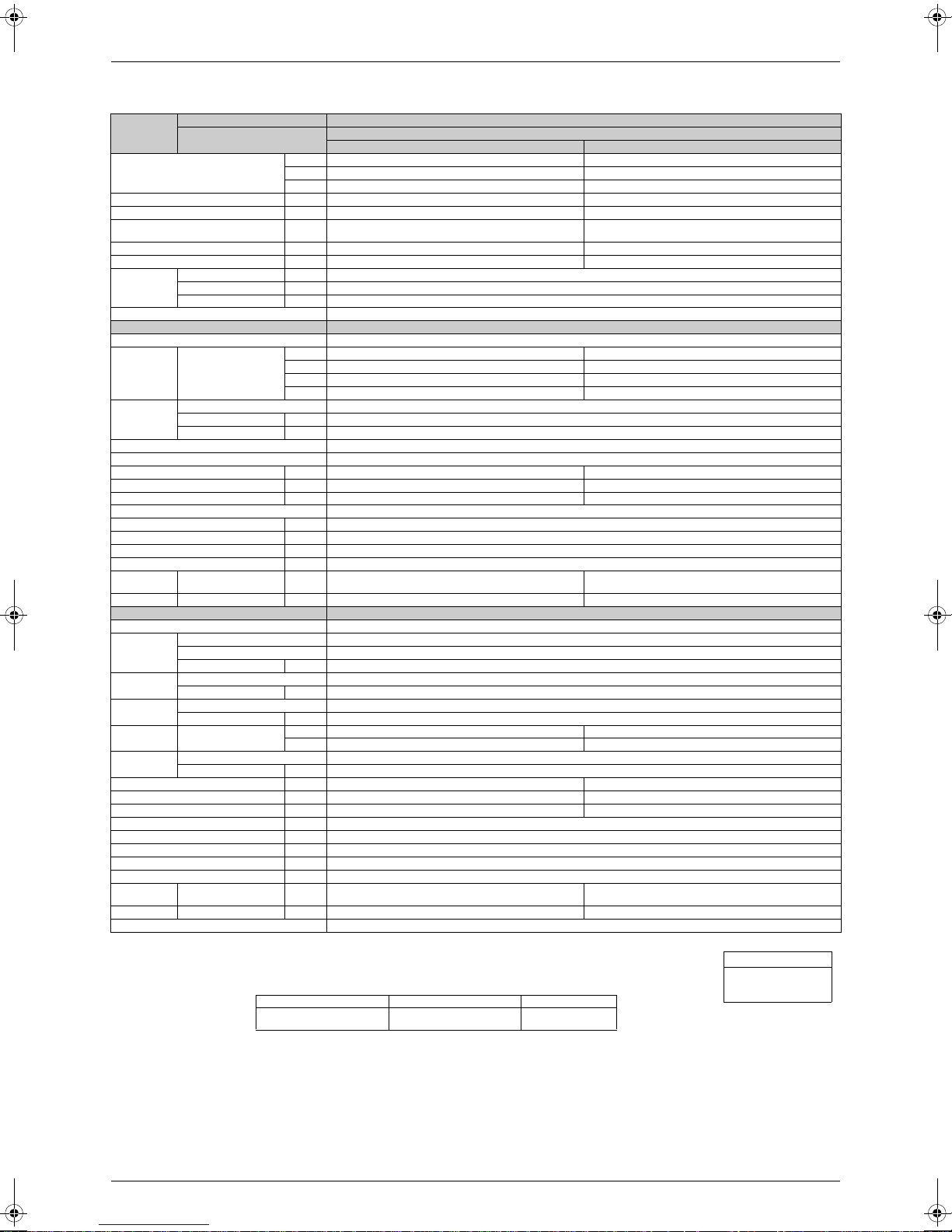
SiENBE04-512A Specifications
50Hz 230V
Models
Capacity
Rated (Min.~Max.)
Moisture Removal L/h 1.9 —
Running Current (Rated) A 4.9 5.4
Power Consumption
Rated (Min.~Max.)
Power Factor % 94.3 95.4
COP (Rated) W/W 3.21 3.42
Piping
Connections
Heat Insulation Both Liquid and Gas Pipes
Indoor Units ATXS35DAVMB
Front Panel Color White
Air Flow Rate
Fan
Air Direction Control Right, Left, Horizontal, Downward
Air Filter Removable / Washable / Mildew Proof
Running Current (Rated) A 0.18 0.18
Power Consumption (Rated) W 40 40
Power Factor % 96.6 96.6
Temperature Control Microcomputer Control
Dimensions (H×W×D) mm 273×784×195
Packaged Dimensions (H×W×D) mm 258×834×325
Weight kg 7.5
Gross Weight kg 11
Operation
Sound
Sound Power H dBA 57 57
Outdoor Units ARXS35C2VMB
Casing Color Ivory White
Compressor
Refrigerant
Oil
Refrigerant
Air Flow Rate m³/min (cfm)
Fan
Running Current (Rated) A 4.72 5.22
Power Consumption (Rated) W 1,020 1,130
Power Factor % 94.0 94.1
Starting Current A 5.4
Dimensions (H×W×D) mm 550×765×285
Packaged Dimensions (H×W×D) mm 589×882×363
Weight kg 32
Gross Weight kg 38
Operation
Sound
Sound Power H dBA 62 63
Drawing No. 3D050957
Indoor Units ATXS35DAVMB
Outdoor Units
kW 3.4 (1.4~3.8) 4.0 (1.4~5.0)
Btu/h 11,600 (4,750~12,950) 13,650 (4,750~17,050)
kcal/h 2,920 (1,200~3,270) 3,440 (1,200~4,300)
W 1,060 (300~1,300) 1,170 (310~1,590)
Liquid mm φ 6.4
Gas mm φ 9.5
Drain mm φ18.0
H 7.7 (272) 8.1 (286)
m³/min
(cfm)
Type Cross Flow Fan
Motor Output W 18
Speed Steps 5 Steps, Silent, Auto
H/M/L/SL dBA 39 / 33 / 26 / 23 39 / 34 / 29 / 26
Type Hermetically Sealed Swing Type
Model 1YC23NXD#A
Motor Output W 600
Type FVC50K
Charge L 0.375
Type R-410A
Charge kg 1.00
Type Propeller
Motor Output W 35
H/L dBA 47 / 44 48 / 45
M 6.0 (212) 6.7 (237)
L 4.4 (155) 5.3 (187)
SL 3.8 (134) 4.6 (162)
H 31.3 (1,105) 28.1 (992)
L 22.4 (791) 22.4 (791)
Cooling Heating
ARXS35C2VMB
Note: MAX. interunit piping length: 20m
MAX. interunit height difference: 15m
Amount of additional charge of refrigerant 20g/m for piping length exceeding 10m
The data are based on the conditions shown in the table below.
Cooling Heating Piping Length
Indoor ; 27°CDB/19°CWB
Outdoor ; 35°CDB/24°CWB
Specifications 19
Indoor ; 20°CDB
Outdoor ; 7°CDB/6°CWB
7.5m
Conversion Formulae
kcal/h=kW×860
Btu/h=kW×3414
cfm=m³/min×35.3
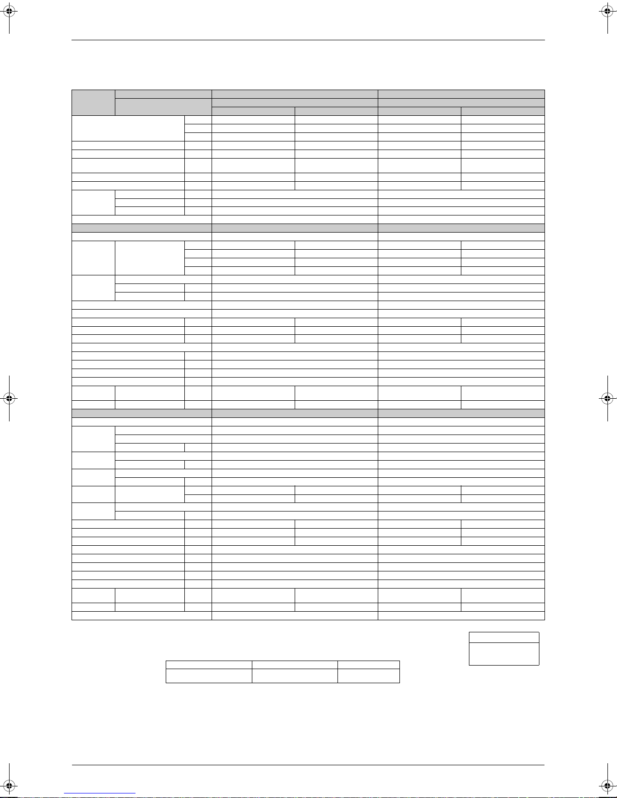
Specifications SiENBE04-512A
1.2.2 Standard Grade Models
50Hz 230V
Models
Capacity
Rated (Min.~Max.)
Moisture Removal L/h 0.9 — 1.2 —
Running Current (Rated) A 3.3 4.0 3.7 4.4
Power Consumption
Rated (Min.~Max.)
Power Factor % 81.7 82.6 82.3 82.5
COP (Rated) W/W 3.23 3.42 3.21 3.41
Piping
Connections
Heat Insulation Both Liquid and Gas Pipes Both Liquid and Gas Pipes
Indoor Units FTXS20CVMB(9) FTXS25CVMB(9)(8)
Front Panel Color White White
Air Flow Rate
Fan
Air Direction Control Right, Left, Horizontal, Downward Right, Left, Horizontal, Downward
Air Filter Removable / Washable / Mildew Proof Removable / Washable / Mildew Proof
Running Current (Rated) A 0.18 0.18 0.18 0.18
Power Consumption (Rated) W 40 40 40 40
Power Factor % 96.6 96.6 96.6 96.6
Temperature Control Microcomputer Control Microcomputer Control
Dimensions (H×W×D) mm 273×784×195 273×784×195
Packaged Dimensions (H×W×D) mm 258×834×325 258×834×325
Weight kg 7.5 7.5
Gross Weight kg 11 11
Operation
Sound
Sound Power H dBA 56 56 56 56
Outdoor Units RXH20CVMB7 RXH25CVMB7
Casing Color Ivory White Ivory White
Compressor
Refrigerant
Oil
Refrigerant
Air Flow Rate
Fan
Running Current (Rated) A 3.12 3.82 3.52 4.22
Power Consumption (Rated) W 580 720 660 795
Power Factor % 80.8 81.9 81.5 81.9
Starting Current A 4.0 4.4
Dimensions (H×W×D) mm 560×695×265 560×695×265
Packaged Dimensions (H×W×D) mm 599×824×337 599×824×337
Weight kg 31 31
Gross Weight kg 36 36
Operation
Sound
Sound Power H dBA 61 62 61 62
Drawing No. 3D048304 3D048305
Indoor Units FTXS20CVMB(9) FTXS25CVMB(9)(8)
Outdoor Units
kW 2.0 (1.3~2.6) 2.6 (1.3~4.0) 2.25 (1.3~3.0) 2.85(1.3~4.5)
Btu/h 6,800 (4,450~8,850) 8,850 (4,450~13,650) 7,650 (4,450~10,250) 9,700 (4,450~15,350)
kcal/h 1,720 (1,120~2,240) 2,240 (1,120~3,440) 1,940 (1,120~2,580) 2,450 (1,120~3,870)
W 620 (430~945) 760 (350~1,310) 700 (430~1,200) 835 (350~1,610)
Liquid mm φ 6.4 φ 6.4
Gas mm φ 9.5 φ 9.5
Drain mm φ18.0 φ 18.0
H 7.7 (272) 7.8 (275) 7.7 (272) 7.8 (275)
m³/min
(cfm)
Type Cross Flow Fan Cross Flow Fan
Motor Output W 18 18
Speed Steps 5 Steps, Silent, Auto 5 Steps, Silent, Auto
H/M/L/SL dBA 38 / 32 / 25 / 22 38 / 33 / 28 / 25 38 / 32 / 25 / 22 38 / 33 / 28 / 25
Type Hermetically Sealed Rotary Type Hermetically Sealed Rotary Type
Model 5RS092XDH01 5RS092XDH01
Motor Output W 650 650
Type RB68A RB68A
Charge L 0.320 0.320
Type R-410A R-410A
Charge kg 0.79 0.79
m³/min
(cfm)
Type Propeller Propeller
Motor Output W 25 25
H/L dBA 46 / — 47 / — 46 / — 47 / —
M 5.9 (208) 6.5 (230) 5.9 (208) 6.5 (230)
L 4.2 (148) 5.3 (187) 4.2 (148) 5.3 (187)
SL 3.6 (127) 4.6 (162) 3.6 (127) 4.6 (162)
H 29 (1,025) 25.5 (901) 29 (1,025) 25.5 (901)
L————
Cooling Heating Cooling Heating
RXH20CVMB7 RXH25CVMB7
Note: MAX. interunit piping length: 15m
MAX. interunit height difference: 15m
Amount of additional charge of refrigerant 20g/m for piping length exceeding 10m
The data are based on the conditions shown in the table below.
Cooling Heating Piping Length
Indoor ; 27°CDB/19°CWB
Outdoor ; 35°CDB/24°CWB
20 Specifications
Indoor ; 20°CDB
Outdoor ; 7°CDB/6°CWB
7.5m
Conversion Formulae
kcal/h=kW×860
Btu/h=kW×3414
cfm=m³/min×35.3
SiENBE04-512A Specifications
50Hz 230V
Models
Capacity
Rated (Min.~Max.)
Moisture Removal L/h 1.7 —
Running Current (Rated) A 4.9 4.9
Power Consumption
Rated (Min.~Max.)
Power Factor % 92.7 93.6
COP (Rated) W/W 3.01 3.41
Piping
Connections
Heat Insulation Both Liquid and Gas Pipes
Indoor Units FTXS35CVMB(9)(8)
Front Panel Color White
Air Flow Rate
Fan
Air Direction Control Right, Left, Horizontal, Downward
Air Filter Removable / Washable / Mildew Proof
Running Current (Rated) A 0.18 0.18
Power Consumption (Rated) W 40 40
Power Factor % 96.6 96.6
Temperature Control Microcomputer Control
Dimensions (H×W×D) mm 273×784×195
Packaged Dimensions (H×W×D) mm 258×834×325
Weight kg 7.5
Gross Weight kg 11
Operation
Sound
Sound Power H dBA 57 57
Outdoor Units RXH35CVMB7
Casing Color Ivory White
Compressor
Refrigerant
Oil
Refrigerant
Air Flow Rate
Fan
Running Current (Rated) A 4.72 4.72
Power Consumption (Rated) W 1,005 1,015
Power Factor % 92.6 93.5
Starting Current A 4.9
Dimensions (H×W×D) mm 560×695×265
Packaged Dimensions (H×W×D) mm 599×824×337
Weight kg 33
Gross Weight kg 38
Operation
Sound
Sound Power dBA 63 63
Drawing No. 3D048306
Indoor Units FTXS35CVMB(9)(8)
Outdoor Units
kW 3.15 (1.4~3.8) 3.6 (1.4~5.0)
Btu/h 10,750 (4,750~12,950) 12,300 (4,750~17,050)
kcal/h 2,710 (1,200~3,270) 3,100 (1,200~4,300)
W 1,045 (460~1,425) 1,055 (405~1,900)
Liquid mm φ 6.4
Gas mm φ 9.5
Drain mm φ 18.0
H 7.7 (272) 8.1 (286)
m³/min
(cfm)
Type Cross Flow Fan
Motor Output W 18
Speed Steps 5 Steps, Silent, Auto
H/M/L/SL dBA 39 / 33 / 26 / 23 39 / 34 / 29 / 26
Type Hermetically Sealed Rotary Type
Model 5RS092XDH01
Motor Output W 650
Type RB68A
Charge L 0.320
Type R-410A
Charge kg 1.01
m³/min
(cfm)
Type Propeller
Motor Output W 25
H/L dBA 48 / — 48 / —
M 6.0 (212) 6.7 (237)
L 4.4 (155) 5.3 (187)
SL 3.8 (134) 4.6 (162)
H 27.5 (972) 23.5 (830)
L— —
Cooling Heating
RXH35CVMB7
Note: MAX. interunit piping length: 15m
MAX. interunit height difference: 15m
Amount of additional charge of refrigerant 20g/m for piping length exceeding 10m
The data are based on the conditions shown in the table below.
Cooling Heating Piping Length
Indoor ; 27°CDB/19°CWB
Outdoor ; 35°CDB/24°CWB
Specifications 21
Indoor ; 20°CDB
Outdoor ; 7°CDB/6°CWB
7.5m
Conversion Formulae
kcal/h=kW×860
Btu/h=kW×3414
cfm=m³/min×35.3
 Loading...