

Daikin FTK25JV1NB9, FTK25JVET9, FTK25JVEA9, FTK35JVE9, FTK35JVEA9 Service Manual
...
Si04-115
Inverter Pair
FTK(X)-J / RK(X)-J Series
[Applied Models]
!!!!Inverter Pair : Cooling Only
!!!!Inverter Pair : Heat Pump
Service
Manual

Si04-115
Table of Contents i
Inverter Pair
Inverter PairInverter Pair
Inverter Pair
FTK(X)-J / RK(X)-J Series
FTK(X)-J / RK(X)-J SeriesFTK(X)-J / RK(X)-J Series
FTK(X)-J / RK(X)-J Series
!Cooling Only
Indoor Unit
FTK25JVE9 FTK25JVEA9 FTK25JVET9 FTK25JV1NB9
FTK35JVE9 FTK35JVEA9 FTK35JVET9 FTK35JV1NB9
Outdoor Unit
RK25JVE9 RK25JVEA9 RK25JVET9 RK25JV1NB9
RK35JVE9 RK35JVEA9 RK35JVET9 RK35JV1NB9
!Heat Pump
Indoor Unit
FTX25JVEA9 FTX25JVET9 FTX25JV1NB9
FTX35JVEA9 FTX35JVET9 FTX35JV1NB9
Outdoor Unit
RX25JVEA9 RX25JVET9 RX25JV1NB9
RX35JVEA9 RX35JVET9 RX35JV1NB9

Si04-115
ii Table of Contents
Inverter Pair FTK(X)-J / RK(X)-J Series........................................... i
1. Introduction .............................................................................................v
1.1 Safety Cautions........................................................................................v
Part 1 List of Function ..................................................................1
1. Functions.................................................................................................2
1.1 Indoor Unit and Outdoor Unit ...................................................................2
Part 2 Specification ......................................................................3
1. Specifications..........................................................................................4
1.1 Cooling Only.............................................................................................4
1.2 Heat Pump ...............................................................................................8
Part 3 Printed Circuit Board Connector Wiring Diagram ...........11
1. Printed Circuit Board Connector Wiring Diagram and Name................12
1.1 FTK25/35J Series, FTX25/35J Series....................................................12
1.2 RK25/35J Series, RX25/35J Series .......................................................15
Part 4 Main Function...................................................................17
1. General Functionality............................................................................18
1.1 Functions of Thermistors........................................................................18
1.2 Operating Modes....................................................................................20
1.3 Frequency Principle................................................................................21
1.4 Defrost Control .......................................................................................23
1.5 Forced Operation Mode .........................................................................24
1.6 Wide-angle Flaps, Diffuser, Louveres and Autoswing............................25
1.7 Fan Speed Control for Indoor Units........................................................26
1.8 Fan Speed Control for Outdoor Units.....................................................27
1.9 General Functions..................................................................................28
1.10 Intelligent Eye.........................................................................................30
1.11 Good Sleep Cooling Control...................................................................32
1.12 Automatic Operation...............................................................................33
1.13 Input Current Control..............................................................................34
1.14 Freeze Protection Function in Cooling ...................................................35
1.15 Peak-Cut Control Function.....................................................................36
1.16 Four-Way Valve Function Compensation...............................................37
1.17 Compressor Protection Function............................................................38
1.18 Wet Operation Protection.......................................................................39
1.19 Dew Condensation Sweating Prevention Function ................................40
Part 5 System Configuration.......................................................41
1. Instruction..............................................................................................42
1.1 FTK25 / 35J, FTX25 / 35J ......................................................................42
Part 6 Service Diagnosis.............................................................61
1. Caution for Diagnosis............................................................................62
1.1 Troubleshooting with The Operation Lamp ............................................62

Si04-115
Table of Contents iii
2. Problem Symptoms and Measures.......................................................63
3. Service Check Function........................................................................64
3.1 ARC423 Series.......................................................................................64
4. Code Indication on The Remote Controller...........................................65
4.1 Error Codes and Description of Fault.....................................................65
5. Trouble shooting ...................................................................................66
5.1 Faulty PCB .............................................................................................66
5.2 Operation Shutdown Due to High-Pressure Control or
Freeze-Up Protection (Thermistor Activation)........................................67
5.3 Operation Halt Due to Fan Motor (AC Motor) or Related Abnormality...68
5.4 Operation Halt Due to Detection of Thermistor or
Related Abnormality...............................................................................69
5.5 Faulty Indoor Unit PCB...........................................................................70
5.6 Faulty Indoor Unit PCB...........................................................................71
5.7 Power Supply Abnormalities or Faulty Indoor Printed Circuit Boards ....72
5.8 Signal Transmission Error (Between Indoor and Outdoor Units)...........73
5.9 Operation Halt Due to Detection of CT Error..........................................74
5.10 Operation Halt Due to Thermistor Error or Disconnection Detection .....75
5.11 Operation Halt Due to Compressor Startup Error ..................................76
5.12 Output Overcurrent.................................................................................77
5.13 Faulty Outdoor Unit PCB........................................................................79
5.14 Faulty Outdoor Unit PCB and Transmitting/Receiving Circuit................80
5.15 Operation Halt Due to Detection of Input Over Current..........................81
5.16 Interrupt due to OL Action ......................................................................83
6. Check.. .................................................................. .... ............................85
6.1 How to Check.........................................................................................85
Part 7 Removal Procedure ..........................................................93
1. For FTK25J, FTK35J, FTX25J, FTX35J...............................................94
1.1 Removal of Air Filter...............................................................................94
1.2 Removal of Front Grille ..........................................................................97
1.3 Removal of Horizontal Blade and Vertical Blade..................................100
1.4 Removal of Switch Box, PC Board and Swing Motor...........................102
1.5 Removal of Heat Exchanger ................................................................108
1.6 Install of Drain Plug ..............................................................................111
1.7 Removal of Fan Rotor and Motor.........................................................112
2. For RK25J, RK35J, RX25J, RX35J.....................................................116
2.1 Removal of External Casing.................................................................116
2.2 Removal of Bell mouth and Left Side Plate..........................................119
2.3 Removal of PC Board and Switch Box.................................................120
2.4 Removal of Propeller Fan and Fan Motor ............................................126
2.5 Removal of Compressor Noise Absorption Pad...................................128
2.6 Removal of Partition Plate and Reactor. ..............................................130
2.7 Removal of Four-way Valve. ................................................................132
2.8 Removal of Compressor.......................................................................134
Part 8 Others .............................................................................137
1. Others .................................................................................................138
1.1 Explanation...........................................................................................138

Si04-115
iv Table of Contents
Part 9 Appendix.........................................................................141
1. Piping Diagram....................................................................................142
1.1 Indoor Unit............................................................................................142
1.2 Outdoor Unit.........................................................................................143
2. Wiring Diagram ...................................................................................145
2.1 Indoor Unit............................................................................................145
2.2 Outdoor Unit.........................................................................................147
Index .............................................................................................i
Drawings & Flow Charts ...............................................................iii
Si04-115 Introduction
v
1. Introduction
1.1 Safety Cautions
Cautions and
Warnings
"
Be sure to read the following safety cautions before conducting repair work.
"
The caution items are classified into “ Warning” and “ Caution”. The “ Warning”
items are especially important since they can lead to death or serious injury if they are not
followed closely. The “ Caution” items can also lead to serious accidents under some
conditions if they are not followed. Therefore, be sure to observe all the safety caution items
described below.
"
About the pictograms
This symbol indicates an item for which caution must be exercised.
The picto g ra m shows th e ite m to which a tte n tion must be p a id .
This symbol indicates a prohibited action.
The proh ib ited ite m or action is s h o w n in s ide o r near the symbol.
This symbol indicates an action that must be taken, or an instruction.
The instruction is shown inside o r near the symbol.
"
After the repair work is complete, be sure to conduct a test operation to ensure that the
equipment operates normally, and explain the cautions for operating the product to the
customer
1.1.1 Caution in Repair.
Warning
Be sure to disconnect the power cable plug from the plug socket before
disassembling the equipment for a repair.
Working on the equipment that is connected to a power supply can cause an
electrical shook.
If it is necessary to supply power to the equipment to conduct the repair or
inspecting the circuits, do not touch any electrically charged sections of the
equipment.
If the refrigerant gas discharges during the repair work, do not touch the
discharging refrigerant gas.
The refrigerant gas can cause frostbite.
When disconnecting the suction or discharge pipe of the compressor at the
welded section, release the refrigerant gas completely at a well-ventilated
place first.
If there is a gas remaining inside the compressor, the refrigerant gas or
refrigerating machine oil discharges when the pipe is disconnected, and it can
cause injury.
If the refrigerant gas leaks during the repair work, ventilate the area. The
refrigerant gas can generate toxic gases when it contacts flames.
The step-up capacitor supplies high-voltage electricity to the electrical
components of the outdoor unit.
Be sure to discharge the capacitor completely before conducting repair work.
A charged capacitor can cause an electrical shock.
Do not start or stop the air conditioner operation by plugging or unplugging the
power cable plug.
Plugging or unplugging the power cable plug to operate the equipment can
cause an electrical shock or fire.
Introduction Si04-115
vi
1.1.2 Cautions Regarding Products after Repair
Caution
Do not repair the electrical components with wet hands.
Working on the equipment with wet hands can cause an electrical shock.
Do not clean the air conditioner by splashing water.
Washing the unit with water can cause an electrical shock.
Be sure to provide the grounding when repairing the equipment in a humid or
wet place, to avoid electrical shocks.
Be sure to turn off the power switch and unplug the power cable when cleaning
the equipment.
The internal fan rotates at a high speed, and cause injury.
Do not tilt the unit when removing it.
The water inside the unit can spill and wet the furniture and floor.
Be sure to check that the refrigerating cycle section has cooled down
sufficiently before conducting repair work.
Working on the unit when the refrigerating cycle section is hot can cause burns.
Use the welder in a well-ventilated place.
Using the welder in an enclosed room can cause oxygen deficiency.
Warning
Be sure to use parts listed in the service parts list of the applicable model and
appropriate tools to conduct repair work. Never attempt to modify the
equipment.
The use of inappropriate parts or tools can cause an electrical shock,
excessive heat generation or fire.
When relocating the equipment, make sure that the new installation site has
sufficient strength to withstand the weight of the equipment.
If the installation site does not have sufficient strength and if the installation
work is not conducted securely, the equipment can fall and cause injury.
Be sure to install the product correctly by using the provided standard
installation frame.
Incorrect use of the installation frame and improper installation can cause the
equipment to fall, resulting in injury.
For integral units
only
Be sure to install the product securely in the installation frame mounted on a
window frame.
If the unit is not securely mounted, it can fall and cause injury.
For integral units
only
Be sure to use an exclusive power circuit for the equipment, and follow the
technical standards related to the electrical equipment, the internal wiring
regulations and the instruction manual for installation when conducting
electrical work.
Insufficient power circuit capacity and improper electrical work can cause an
electrical shock or fire.
Si04-115 Introduction
vii
1.1.3 Inspection after Repair
Be sure to use the specified cable to connect between the indoor and outdoor
units. Make the connections securely and route the cable properly so that there
is no force pulling the cable at the connection terminals.
Improper connections can cause excessive heat generation or fire.
When connecting the cable between the indoor and outdoor units, make sure
that the terminal cover does not lift off or dismount because of the cable.
If the cover is not mounted properly, the terminal connection section can cause
an electrical shock, excessive heat generation or fire.
Do not damage or modify the power cable.
Damaged or modified power cable can cause an electrical shock or fire.
Placing heavy items on the power cable, and heating or pulling the power cable
can damage the cable.
Do not mix air or gas other than the specified refrigerant (R22) in the refrigerant
system.
If air enters the refrigerating system, an excessively high pressure results,
causing equipment damage and injury.
If the refrigerant gas leaks, be sure to locate the leak and repair it before
charging the refrigerant. After charging refrigerant, make sure that there is no
refrigerant leak.
If the leak cannot be located and the repair work must be stopped, be sure to
perform pump-down and close the service valve, to prevent the refrigerant gas
from leaking into the room. The refrigerant gas itself is harmless, but it can
generate toxic gases when it contacts flames, such as fan and other heaters,
stoves and ranges.
When replacing the coin battery in the remote controller, be sure to disposed
of the old battery to prevent children from swallowing it.
If a child swallows the coin battery, see a doctor immediately.
Warning
Caution
Installation of a leakage breaker is necessary in some cases depending on the
conditions of the installation site, to prevent electrical shocks.
Do not install the equipment in a place where there is a possibility of
combustible gas leaks.
If a combustible gas leaks and remains around the unit, it can cause a fire.
Be sure to install the packing and seal on the installation frame properly.
If the packing and seal are not installed properly, water can enter the room and
wet the furniture and floor.
For integral units
only
Warning
Check to make sure that the power cable plug is not dirty or loose, then insert
the plug into a power outlet all the way.
If the plug has dust or loose connection, it can cause an electrical shock or fire.
If the power cable and lead wires have scratches or deteriorated, be sure to
replace them.
Damaged cable and wires can cause an electrical shock, excessive heat
generation or fire.
Do not use a joined power cable or extension cable, or share the same power
outlet with other electrical appliances, since it can cause an electrical shock,
excessive heat generation or fire.
Introduction Si04-115
viii
1.1.4 Using Icons
Icons are used to attract the attention of the reader to specific information. The meaning of each
icon is described in the table below:
1.1.5 Using Icons List
Caution
Check to see if the parts and wires are mounted and connected properly, and
if the connections at the soldered or crimped terminals are secure.
Improper installation and connections can cause excessive heat generation,
fire or an electrical shock.
If the installation platform or frame has corroded, replace it.
Corroded installation platform or frame can cause the unit to fall, resulting in
injury.
Check the grounding, and repair it if the equipment is not properly grounded.
Improper grounding can cause an electrical shock.
Be sure to measure the insulation resistance after the repair, and make sure
that the resistance is 1 Mohm or higher.
Faulty insulation can cause an electrical shock.
Be sure to check the drainage of the indoor unit after the repair.
Faulty drainage can cause the water to enter the room and wet the furniture
and floor.
Icon Type of
Information
Description
Note:
Note A “note” provides information that is not indispensable, but may
nevertheless be valuable to the reader, such as tips and tricks.
Caution
Caution A “caution” is used when there is danger that the reader, through
incorrect manipulation, may damage equipment, loose data, get
an unexpected result or has to restart (part of) a procedure.
Warning
Warning A “warning” is used when there is danger of personal injury.
Reference A “reference” guides the reader to other places in this binder or
in this manual, where he/she will find additional information on a
specific topic.

Si04-115
List of Function 1
Part 1
List of Function
1.Functions.................................................................................................2
1.1 Indoor Unit and Outdoor Unit ...................................................................2
Functions Si04-115
2 List of Function
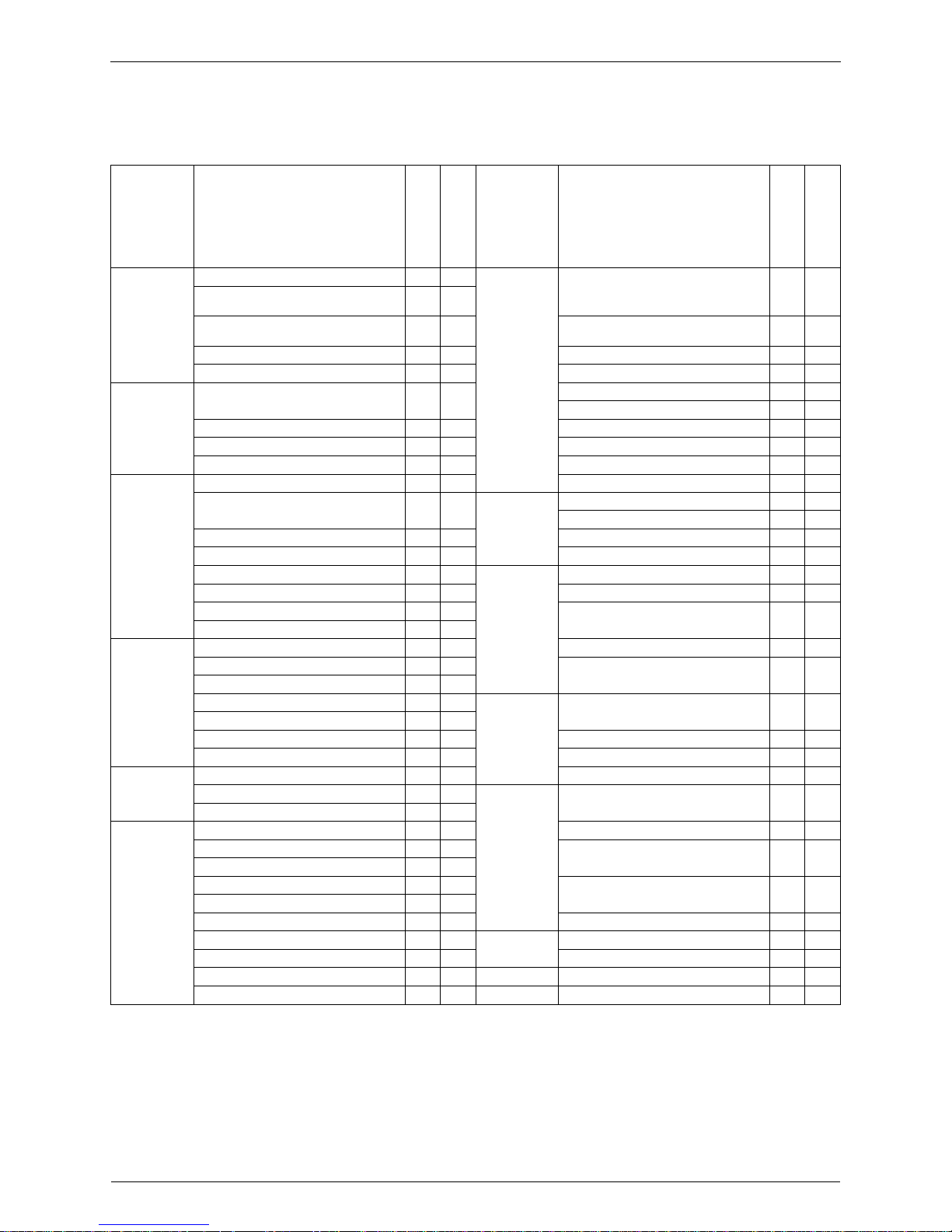
1. Functions
1.1 Indoor Unit and Outdoor Unit
Category Functions
FTK25·35J Series
RK25·35J Series
FTX25·35J Series
RX25·35J Series
Category Functions
FTK25·35J Series
RK25·35J Series
FTX25·35J Series
RX25·35J Series
Basic
Function
Inverter (with Inverter Power Control)
##
Health
Health &
Clean
Air Purifying Filter with Bacteriostatic,
Virustatic & Deodorizing Functions
##
Operation Limit for Cooling (°C)
10
~4610~46
Operation Limit for Heating (°C) —
-10
~15
Longlife Filter — —
Microprocessor Control
##
Ultra-Longlife Filter (Option) — —
PAM Control — — Photocatalytic Deodorizing Filter — —
Compressor
Horizontal Scroll, Oval Scroll
Compressor (DAIKIN SCROLL)
——
Photocatalytic Filter with UV Lamp — —
Mold Proof Air Filter
##
Swing Compressor (DAIKIN ROTARY) — — Washable Grille
##
Rotary Compressor
##
Filter Cleaning Indicator — —
Reluctance DC Motor — — Healthy Cooling Operation — —
Comfortable
Airflow
Dual Flaps — — Good-Sleep Cooling Operation
##
Power-Airflow Dual Flaps
#
5step#5step
Timer
72-Hour On/Off Timer — —
24-Hour On/Off Timer
##
Power-Airflow Diffuser — — Night Set Mode
##
Wide-Angle Louvers
##
Just Fit Thermostatic Timer — —
Vertical Auto-Swing (Up and Down)
##
Worry Free
“Reliability &
Durability”
Auto-Restart (after Power Failure)
##
Horizontal Auto-Swing (Right and Left) — — Self-Diagnosis (Digital, LED) Display
##
3-D Air flow — —
The Remote Controller Loss Prevention
with the Chain (Option)
##
3-Step Airflow (H/P Only) — —
“Comfortable
Control”
Comfort
Control
Auto Fan Speed
##
Wiring Error Check — —
Silent-Operation Control (Automatic) — —
Anticorrosion Treatment of Outdoor
Hear Exchanger
##
Outdoor Unit Silent Operation (Manual) — —
Intelligent Eye
##
Flexibility
Multi-Split / Split Type Compatible
Indoor Unit
##
Quick Warming Function —
#
Hot-Start Function —
#
Flexible Voltage Correspondence
##
Automatic Defrosting —
#
High Ceiling Application — —
Operation
Automatic Operation —
#
Chargeless 10m 10m
Programme Dry Function
##
Remote
Control
5-Rooms Centralized Controller
(Option)
##
Fan Only
#
—
Lifestyle
Convenience
New Powerful Operation (Non-Inverter) — — Field-Supply Timer Operation
##
Inverter Powerful Operation ##
Remote Control Adaptor (Option)
(Normal Open-Pulse Contact)
##
Priority-Room Setting — —
Quiet Operation — —
Remote Control Adaptor (Normal Open
Contact)
##
Laundry Programme Operation — —
Home Leave Operation — — DIII-NET Compatible (Adaptor)
##
Power Selection — —
Remote
Controller
Wireless
##
Indoor Unit On/Off Switch
##
Wired — —
Signal Reception Indicator
##
Temperature Display — —
#
: Holding Functions — : No Functions

Si04-115
Printed Circuit Board Connector Wiring Diagram 3
Part 2
Part 2Part 2
Part 2
Specification
SpecificationSpecification
Specification
1. Specifications..........................................................................................4
1.1 Cooling Only.............................................................................................4
1.2 Heat Pump ...............................................................................................8
Specifications Si04-115
4 Specification
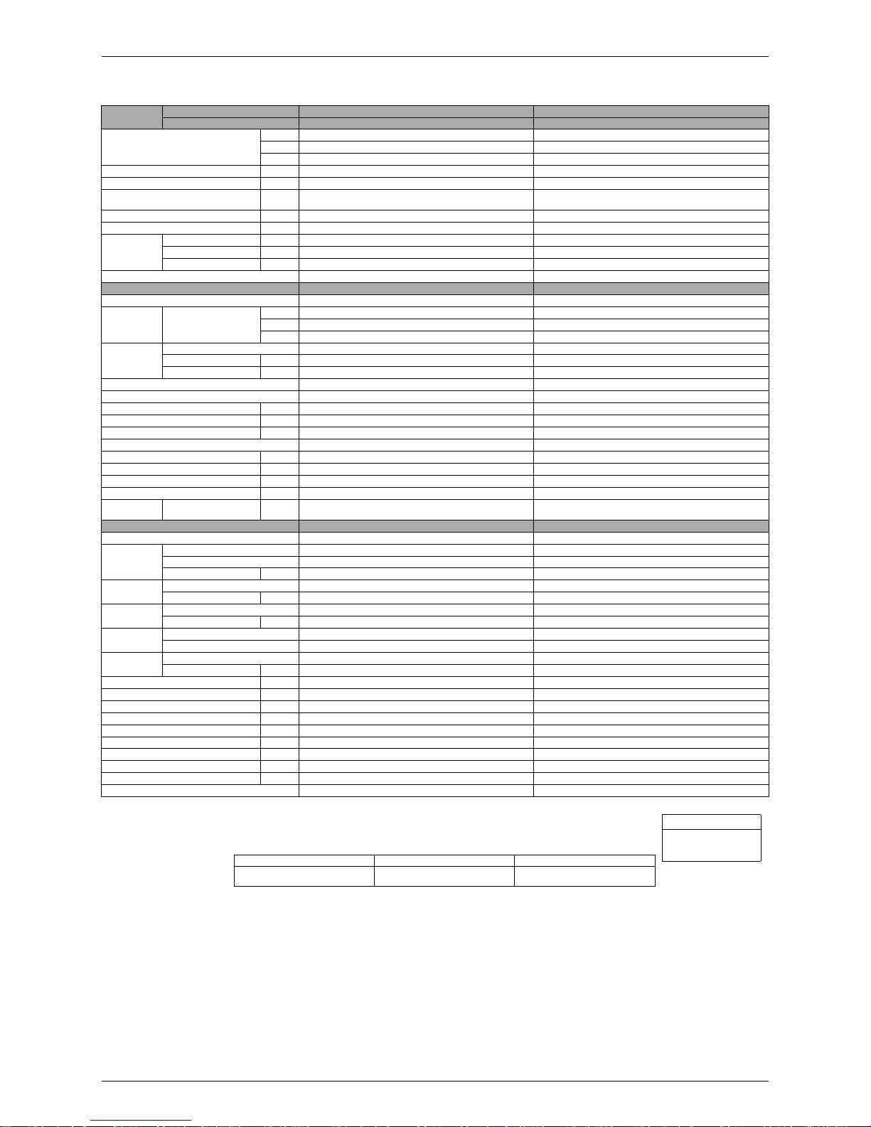
1. Specifications
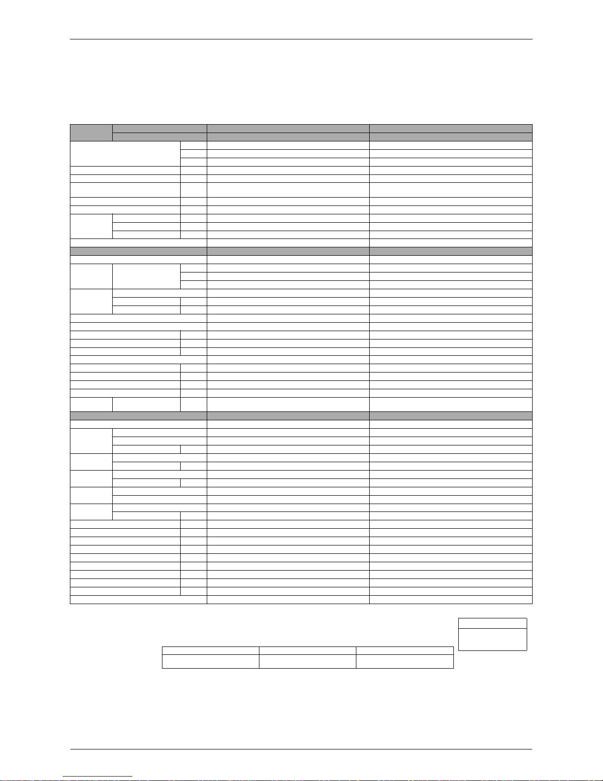
1.1 Cooling Only
220 - 230 - 240V, 50Hz
220 - 230V, 60Hz
Notes:
"
MAX. interunit piping length: 25m
"
MAX. interunit height difference: 15m
"
Amount of additional charge of refrigerant 20g/m for piping length exceeding 10m
"
The data are based on the conditions shows in the table below.
Model
Indoor Units FTK25JVE9 FTK35JVE9
Outdoor Units RK25JVE9 RK35JVE9
Capacity
Rated (M in .~ Max.)
kW 2.55 (1.3~3.2) 3.5 (1.4~4.0)
Btu/h 8,720 (4,400~10,900) 12,000 (4,800~13,700)
kcal/h 2,200 (1,100~2,750) 3,000 (1,200~3,450)
Moisture Removal L/h 1.2 1.9
Running Current (Rated) A 4.6 6.8
Power Consumption Rated
(Min.~Ma x .)
W 880 (430~1,250) 1,150 (500~1,550)
Power Fac tor % 87.0 - 83.2 - 79.7 / 87.0 - 83.2 76.9 - 73.5 - 70.5 / 76.9 - 73.5
COP W/W 2.90 3.04
Piping
Connections
Liquid mm
φ
6.4
φ
6.4
Gas mm
φ
9.5
φ
12.7
Drain mm
φ
18.0
φ
18.0
Heat Insulation Both Liquid and Gas Pipes Both Liquid and Gas Pipes
Indoor Unit FTK25JVE9 FTK35JVE9
Front Panel Color Almond White Almond White
Air Flow Rate
m³/min
(cfm)
H 7.5 (265) 7.8 (275)
M 6.4 (226) 6.7 (237)
L 5.4 (191) 5.5 (194)
Fan
Type Cross Flow Fan Cross Flow Fan
Motor Output W 18 18
Speed Steps 5 Steps and Auto 5 Steps and Auto
Air Direction C o n tro l Right, Le ft, H o r izo n ta l and Downw ard Right, Left, Horizontal a n d D o wnward
Air Filter Remo v a l / Washable / Mildew P roof Removal / Washable / Milde w Proof
Running Curre nt (R ate d) A 0.17 - 0.18 - 0.18 / 0.21 - 0.21 0.17 - 0.18 - 0.18 / 0.21 - 0.21
Power Consumption (Rated) W 37 - 40 - 43 / 45 - 48 37 - 40 - 43 / 45 - 48
Power Fac tor % 9 8.9 - 96.6 - 99.5 / 97.4 - 99.4 98.9 - 96.6 - 99.5 / 97.4 - 99.4
Temperature Control Microcomputer Control Microcomputer Control
Dimension (H×W×D) mm 273×784×185 273×784×185
Packaged Dimension mm 325×834×258 325×834×258
Weight kg 7.5 7.5
Gross Weight kg 11 11
Operation
Sound
H/M/L dBA 37 / 34 / 30 38 / 35 / 32
Outdoor Unit RK25JVE9 RK35JVE9
Casing Color Ivory White Ivory White
Compressor
Type H ermetically Sealed Rotary Type Hermetically Sealed Rotary Type
Model RC1X26BTNT RC1X26BTNT
Motor Output W 750 750
Refrigerant
Oil
Model SUNISO 4GSD.I. SUNISO 4GSD.I.
Charge L 0.4 0.4
Refrigerant
Model R22 R22
Charge kg 0.72 0.89
Air Flow Rate
m³/min 28.0 - 29.0 - 30.0 / 29.0 - 30.0 26.5 - 27.5 - 28.0 / 27.5 - 28.0
cfm 988 - 1,024 - 1,059 / 1,024 - 1,059 935 - 971 - 988 / 971 - 988
Fan
Type Prope ller Prop eller
Motor Ou tp u t W 25 2 5
Running C u rre n t (R a te d ) A 4.43 - 4.42 - 4 .4 2 / 4 .3 9 - 4 .39 6.63 - 6.62 - 6.6 2 / 6 .5 9 - 6 .5 9
Power Co nsu m ptio n (Ra ted ) W 843 - 840 - 837 / 835 - 832 1,113 - 1,110 - 1,107 / 1,105 - 1,102
Power Fac tor % 8 6.5 - 82.6 - 78.9 / 86.5 - 82.4 76.3 - 72.9 - 69.7 / 76.2 - 72.7
Starting Current A 4.6 6.8
Dimensions (H×W×D) mm 560×695×265 560×695×265
Packaged Dimension mm 599×797×310 599×797×310
Weight kg 31 32
Gross Weight kg 33 35
Operation Sound dBA 45 - 46 - 47 / 46 - 47 46 - 47 - 48 / 47 - 48
Drawing No. 3D029316 3D029317
Conversion Formulae
kcal/h=kW×860
Btu/h=kW×3414
cfm=m³/min×35.3
Standard Cooling Piping Length
JIS C9612
Indoor ; 27°CDB/19°CWB
Outdoor ; 35°CDB/24°CWB
5m

Si04-115 Specifications
Specification 5
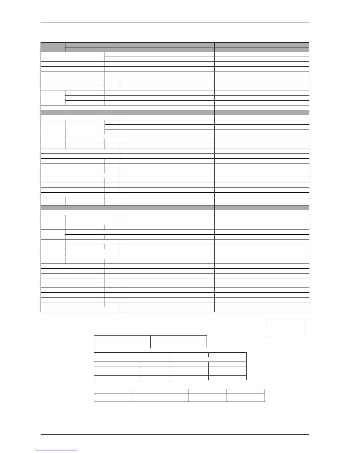
220 - 230 - 240V, 50Hz
Notes:
"
MAX. interunit piping length: 25m
"
MAX. interunit height difference: 15m
"
Amount of additional charge of refrigerant 20g/m for piping length exceeding 10m
"
The data are based on the conditions shows in the table below.
The data on the conditions (AS/NZS3823.1):
(Conditions)
Model
Indoor Units FTK25JVEA9 FTK35JVEA 9
Outdoor Units RK25JVEA9 RK35JVEA9
Capacity
Rated (M in .~ Max.)
kW 2.54 (1.3~3.2) 3.6 (1.4~4.0)
Btu/h 8,700 (4,400~10,900) 12,300 (4,800~13,700)
kcal/h 2,190 (1,100~2,750) 3,100 (1,200~3,450)
Moisture Removal L/h 1.2 1.9
Running Current (Rated) A 5.1 7.0
Power Consumption Rated
(Min.~Ma x .)
W 900 (430~1,250) 1,340 (500~1,550)
Power Factor % 80.2 - 76.7 - 73.5 87.0 - 83.2 - 79.8
COP (Rate d) W/W 2.82 2.69
Piping
Connections
Liquid mm
φ
6.4
φ
6.4
Gas mm
φ
9.5
φ
12.7
Drain mm
φ
18.0
φ
18.0
Heat Insulation Both Liquid and Gas Pipes Both Liquid and Gas Pipes
Indoor Unit FTK25JVEA9 FTK35JVEA9
Front Panel Color Almond White Almond White
Air Flow Rate
m³/min
(cfm)
H 7.5 (265) 7.8 (275)
M 6.4 (226) 6.7 (237)
L 5.4 (191) 5.5 (194)
Fan
Type Cross Flow Fan Cross Flow Fan
Motor Output W 18 18
Speed Steps 5 Steps and Auto 5 Steps and Auto
Air Direction C o n tro l Right, Le ft, H o r izo n ta l and Downw ard Right, Left, Horizontal a n d D o wnward
Air Filter Remo v a l / Washable / Mildew P roof Removal / Washable / Milde w Proof
Running Current (Rated) A 0.17 - 0.18 - 0.18 0.17 - 0.18 - 0.18
Power Consumption (Rated) W 37 - 40 - 43 37 - 40 - 43
Power Factor % 98.9 - 96.6 - 99.5 98.9 - 96.6 - 99.5
Temperature Control Microcomputer Control Microcomputer Control
Dimension (H×W×D) mm 273×784×185 273×784×185
Packaged Dimension mm 325×834×258 325×834×258
Weight kg 7.5 7.5
Gross Weight kg 11 11
Operation
Sound
H/M/L dBA 37 / 34 / 30 38 / 35 / 32
Outdoor Unit RK25JVEA9 RK35JVEA9
Casing Color Ivory White Ivory White
Compressor
Type H ermetically Sealed Rotary Type Hermetically Sealed Rotary Type
Model RC1X26BTNT RC1X26BTNT
Motor Output W 750 750
Refrigerant
Oil
Model SUNISO 4GSD.I. SUNISO 4GSD.I.
Charge L 0.4 0.4
Refrigerant
Model R22 R22
Charge kg 0.72 0.92
Air Flow Rate
m³/min 28.0 - 29.0 - 30.0 26.5 - 27.5 - 28.0
cfm 988 - 1,024 - 1,059 935 - 971 - 988
Fan
Type Prope ller Prop eller
Motor Ou tp u t W 25 2 5
Running Current (Rated) A 4.93 - 4.92 - 4.92 6.83 - 6.82 - 6.82
Power Consumption (Rated) W 863 - 860 - 857 1,303 - 1,300 - 1,297
Power Factor % 79.6 - 76.0 - 72.6 86.7 - 82.9 - 79.2
Starting Current A 5.1 7.0
Dimensions (H×W×D) mm 560×695×265 560×695×265
Packaged Dimension mm 797×310×599 797×310×599
Weight kg 31 32
Gross Weight kg 33 35
Operation Sound dBA 45 - 46 - 47 46 - 47 - 48
Drawing No. 3D029314 3D029315
Conversion Formulae
kcal/h=kW×860
Btu/h=kW×3414
cfm=m³/min×35.3
Standard Cooling Piping Length
JIS C 9612
Indoor ; 27°CDB/19°CWB
Outdoor ; 35°CDB/24°CWB
5m
(Rated) FTK25JVEA FTK35JVEA
Capacity kW 2.5 3.5
Running Current A 5.1 7.0
Power Consumption W 960 1,470
COP W/W 2.60 2.38
Standard Cooling Piping Length Power Source
AS/NZS3823.1
Indoor ; 27°CDB/19°CWB
Outdoor ; 35°CDB/24°CWB
7.5m 50Hz 230V
Specifications Si04-115
6 Specification
220V, 60Hz
Notes:
"
MAX. interunit piping length: 25m
"
MAX. interunit height difference: 15m
"
Amount of additional charge of refrigerant 20g/m for piping length exceeding 10m
"
The data are based on the conditions shows in the table below.
"
The data on the conditions (CNS3615):
(Conditions)
Models
Indoor Units FTK25JVET9 FTK35JVET9
Outdoor Units RK25JVET9 RK35JVE T9
Capacity (Min.~Max.)
kW 1.3~3.2 1.4~4.0
kcal/h 1,100~2,750 1,200~3,450
Moisture Removal L/h 1.2 1.9
Running Current (Min.~Max.) A 3.1~7.1 3.4~8.9
Power Consumption (Min.~Max.) W 470~1,300 520~1,650
Power Factor (Min.~Max.) % 68.9~83.2 69.5~84.3
COP (Min.~Max.) W/W 2.77~2.46 2.69~2.42
EER (Min.~Max.) kcal/h·W 2.34~2.11 2.31~2.09
Piping
Connections
Liquid mm
φ
6.4
φ
6.4
Gas mm
φ
9.5
φ
12.7
Drain mm
φ
18.0
φ
18.0
Heat Insulation Both Liquid and Gas Pipes Both Liquid and Gas Pipes
Indoor Units FTK25JVET9 FTK35JVET9
Front Panel Color Almond White Almond White
Air Flow Rate
m³/min
(cfm)
H7.5 7.8
M6.4 6.7
L5.4 5.5
Fan
Type Cross Flow Fan Cross Flow Fan
Motor Output W 18 18
Speed Steps 5 Steps and Auto 5 Steps and Auto
Air Direction C o n tro l Right, Le ft, H o r izo n ta l and Downw ard Right, Left, Horizontal a n d D o wnward
Air Filter Remo v a l / Washable / Mildew P roof Removal / Washable / Milde w Proof
Running Current (Rated) A 0.21 0.21
Power Consumption (Rated) W 45 45
Power Factor % 97.4 97.4
Temperature Control Microcomputer Control Microcomputer Control
Dimensions (H×W×D) mm 273×784×185 273×784×185
Packaged Dimensions mm 834×325×258 834×325×258
Weight kg 7.5 7.5
Gross Weight kg 11 11
Operation
Sound
H/M/L dBA 37 / 34 / 30 38 / 35 / 32
Outdoor Units RK25JVET9 RK35JVET9
Casing Color Ivory White Ivory White
Compressor
Type H ermetically Sealed Rotary Type Hermetically Sealed Rotary Type
Model RC1X26BTNT RC1X26BTNT
Motor Output W 750 750
Refrigerant
Oil
Model SUNISO 4GSD.I. SUNISO 4GSD.I.
Charge L 0.4 0.4
Refrigerant
Model R22 R22
Charge kg 0.72 0.92
Air Flow Rate m³/min 29.0 27.5
Fan
Type Prope ller Prop eller
Motor Ou tp u t W 25 2 5
Running Curre nt (Min .~M ax .) A 2.89~6.89 3.19~8.69
Power Consumption (Min.~Max.) W 425~1,255 475~1,605
Power Factor (Min.~Max.) % 66.8~82.8 67.7~84.0
Starting Current A 4.3 5.5
Dimensions (H×W×D) mm 560×695×265 560×695×265
Packaged Dimensions (W×D×H) mm 797×310×599 797×310×599
Weight kg 31 32
Gross Weight kg 34 36
Operation Sound dBA 46 47
Drawing No. 3D029306 3D029307
Conversion Formulae
kcal/h=kW×860
Btu/h=kW×3414
cfm=m³/min×35.3
Cooling Piping Length
Indoor ; 27°CDB/1 9 .5 °C WB
Outdoor ; 35°CDB/24°CWB
5m
Models FTK25JVET9 FTK35JVET9
(Rated) Cooling
Capacity kW (kcal/h) 2.0 (1,720) 2.7 (2,350)
Running Current A 3.9 5.0
Power Consumption W 755 1,035
COP (EER) W/W (kcal/h·W) 2.65 (2.27) 2.61 (2.27)
Standard Cooling Piping Length Power Source
CNS3615
Indoor ; 27°CDB/19.5°CWB
Outdoor ; 35°CDB/24°CWB
5m 60Hz 220V
Si04-115 Specifications
Specification 7
230V, 50Hz
Notes:
"
MAX. interunit piping length: 25m
"
MAX. interunit height difference: 15m
"
Amount of additional charge of refrigerant 20g/m for piping length exceeding 10m
"
The data are based on the conditions shows in the table below.
Models
Indoor Units FTK25JAV1NB FTK35JAV1N B
Outdoor Units RK25JV1NB9 RK35JV1NB9
Capacity
Rated (M in .~ Max.)
kW 2.5 (1.3~3.0 ) 3.54 (1.4~3 .8)
Btu/h 8,500 (4,400~10,300) 12,100 (4,800~13,000)
kcal/h 2,150 (1,100~2,600) 3,050 (1,200~3,300)
Moisture Removal L/h 1.2 1.9
Running Current (Rated) A 4.5 6.3
Power Consumption
Rated (M in .~ Max.)
W 945 (430~1,250) 1,345 (470~1,720)
Power Factor % 91.3 92.8
COP (R ate d ) W/W 2.65 2.63
Piping
Connections
Liquid mm
φ
6.4
φ
6.4
Gas mm
φ
9.5
φ
12.7
Drain mm
φ
18.0
φ
18.0
Heat Insulation Both Liquid and Gas Pipes Both Liquid and Gas Pipes
Indoor Units FTK25JAV1NB FTK35JAV1NB
Front Panel Color Almond White Almond White
Air Flow Rate
m³/min
(cfm)
H 7.1 (251) 7.4 (261)
M 5.9 (208 ) 6.0 (212)
L 4.6 (162) 4.7 (166)
Fan
Type Cross Flow Fan Cross Flow Fan
Motor Output W 18 18
Speed Steps 5 Steps and Auto 5 Steps and Auto
Air Direction C o n tro l Right, Le ft, H o r izo n ta l and Downw ard Right, Left, Horizontal a n d D o wnward
Air Filter Remo v a l / Washable / Mildew P roof Removal / Washable / Milde w Proof
Running Current (Rated) A 0.18 0.18
Power Consumption (Rated) W 40 40
Power Factor % 96.6 96.6
Temperature Control Microcomputer Control Microcomputer Control
Dimensions (H×W×D) mm 273×784×185 273×784×185
Packaged Dimensions mm 834×325×258 834×325×258
Weight kg 7.5 7.5
Gross Weight kg 11 11
Operation
Sound
H/M/L dBA 38 / 32 / 26 39 / 33 / 27
Outdoor Units RK25JV1NB9 RK35JV1NB9
Casing Color Ivory White Ivory White
Compressor
Type H ermetically Sealed Rotary Type Hermetically Sealed Rotary Type
Model RC1X26BTNT RC1X26BTNT
Motor Output W 750 750
Refrigerant
Oil
Model SUNISO 4GSD.I. SUNISO 4GSD.I.
Charge L 0.4 0.4
Refrigerant
Model R22 R22
Charge kg 0.72 0.92
Air Flow Rate
m³/min 29.0 27 .5
cfm 1,024 971
Fan
Type Prope ller Prop eller
Motor Ou tp u t W 25 2 5
Running Current (Rated) A 4.32 6.12
Power Consumption (Rated) W 905 1,305
Power Factor % 91.1 92.7
Starting Current A 5.1 6.3
Dimensions (H×W×D) mm 560×695×265 560×695×265
Packaged Dimensions mm 797×310×599 797×310×599
Weight kg 33 35
Gross Weight kg 37 39
Operation Sound dBA 46 47
Drawing No. 3D 027499B 3D027500B
Conversion Formulae
kcal/h=kW×860
Btu/h=kW×3414
cfm=m³/min×35.3
Cooling Heating Piping Length
Indoor ; 27°CDB/19°CWB
Outdoor ; 35°CDB/24°CWB
Indoor ; 20°CDB
Outdoor ; 7°CDB/6 °C WB
7.5m
Specifications Si04-115
8 Specification
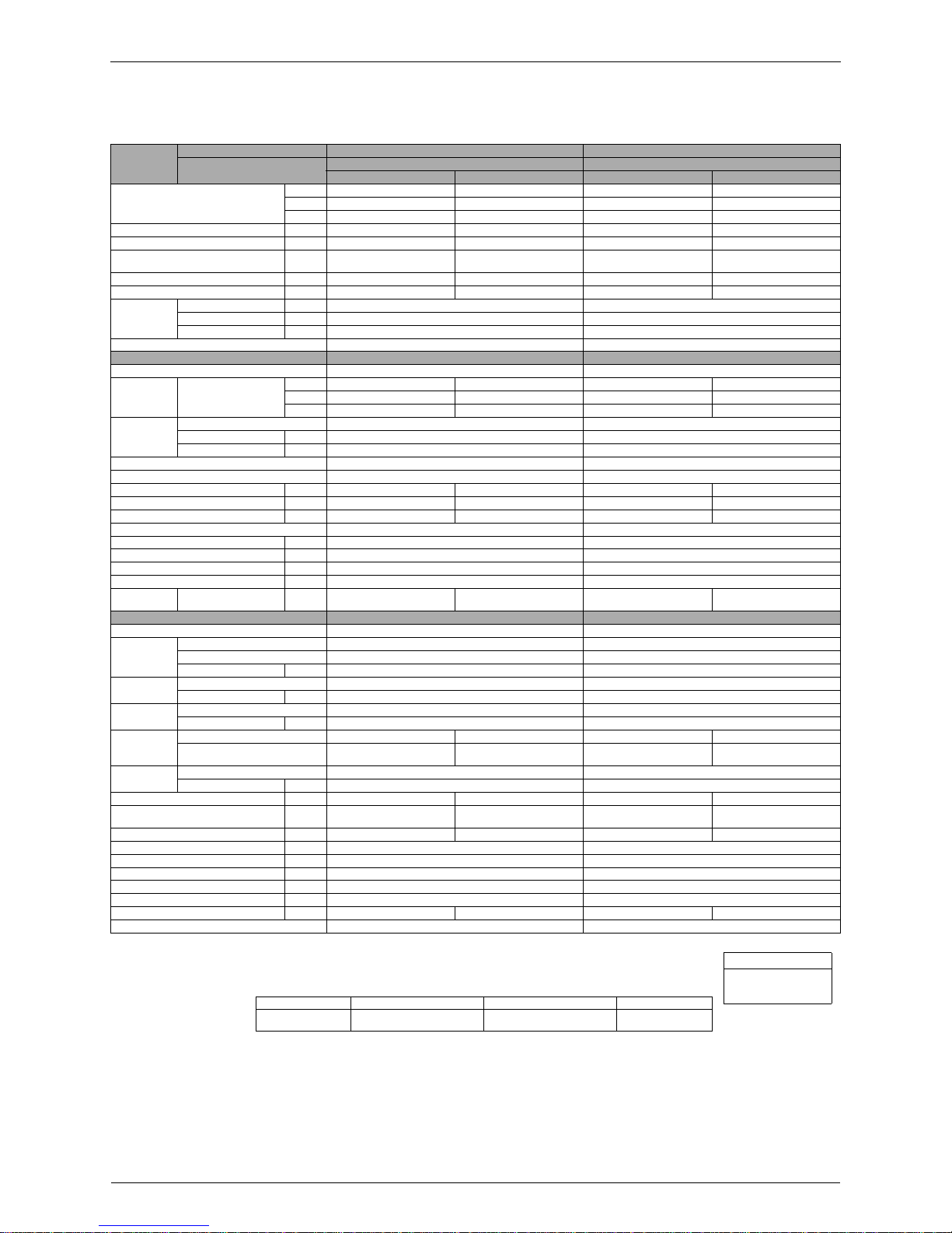
1.2 Heat Pump
220-230-240V, 50Hz / 220-230V, 60Hz
Notes:
"
MAX. interunit piping length: 15m
"
MAX. interunit height difference: 15m
"
Amount of additional charge of refrigerant 20g/m for piping length exceeding 10m
"
The data are based on the conditions shows in the table below.
Models
Indoor Units FTX25JVEA9 FTX35JVEA9
Outdoor Units
RX25JVEA9 RX35JVEA9
Coolin g Heating Cooling Heating
Capacity
Rated (M in .~ Max.)
kW 2.54 (1.3~3.0) 3.4 (1.3~4.0) 3.60 (1.4~3.8) 4.2 (1.4~5.1)
Btu/h 8,700 (4,400~10,300) 11,600 (4,400~13,600) 12,300 (4,800~13,000) 14,300 (4,800~17,600)
kcal/h 2,190 (1,100~2,600) 2,920 (1,100~3,440) 3,100 (1,200~3,300) 3,600 (1,200~4,400)
Moisture Removal L/h 1.2 — 1.9 —
Running Current (Rated) A 5.1 5.6 7.4 7.3
Power Consumption Rated
(Min.~Ma x .)
W 900 (430~1,250) 1,100 (350~1,350) 1,360 (500~1,720) 1,340 (405~1,900)
Power Fac tor % 80.2-76.7-7 3.5 / 80.2-7 6.7 89.3-85.4 -81 .8 / 89.3 -85.4 83.5-79.9-76.6 / 83.5-79 .9 83.4-79.8-7 6.5 / 83.4-7 9.8
COP W/W 2.82 3.09 2.65 3.13
Piping
Connections
Liquid mm
φ
6.4
φ
6.4
Gas mm
φ
9.5
φ
12.7
Drain mm
φ
18.0
φ
18.0
Heat Insulation Both Liquid and Gas Pipes Both Liquid and Gas Pipes
Indoor Units FTX25JVEA9 FTX35JVEA9
Front Panel Color Almond White Almond White
Air Flow Rate
m³/min
(cfm)
H 7.5 (265) 8.8 (311) 7.8 (275) 8.7 (307)
M 6.4 (226) 7.5 (265) 6.7 (237) 7.4 (261)
L 5.4 (191) 6.2 (219) 5.5 (194) 6.2 (219)
Fan
Type Cross Flow Fan Cross Flow Fan
Motor Output W 18 18
Speed Steps 5 Steps and Auto 5 Steps and Auto
Air Direction C o n tro l Right, Le ft, H o r izo n ta l and Downw ard Right, Left, Horizontal a n d D o wnward
Air Filter Remo v a l / Washable / Mildew P roof Removal / Washable / Milde w Proof
Running Curre nt (R ated ) A 0.17-0.18-0.18 / 0.21-0.2 1 0.17-0.18-0 .18 / 0.21 -0.21 0.17-0.18-0.18 / 0.21-0.2 1 0.17-0.18-0 .18 / 0.21 -0 .21
Power Consumption (Rated) W 37-40-43 / 45-48 37-40-43 / 45-48 37-40-43 / 45-48 37-40-43 / 45-48
Power Fac tor % 98.9-96.6-9 9.5 / 97.4-9 9.4 98.9-96.6 -99 .5 / 97.4- 99.4 98.9-96.6 -99 .5 / 97.4-9 9.4 98.9-96.6-99.5 / 97.4-99 .4
Temperature Control Microcomputer Control Microcomputer Control
Dimensions (H×W×D) mm 273×784×185 273×784×185
Packaged Dimensions (W×D×H) mm 834×325×218 834×325×218
Weight kg 7.5 7.5
Gross Weight kg 11 11
Operation
Sound
H/M/L dBA 37 / 34 / 30 37 / 33 / 30 38 / 35 / 32 38 / 35 / 31
Outdoor Units RX25JVEA9 RX35JVEA9
Casing Color Ivory White Ivory White
Compressor
Type H ermetically Sealed Rotary Type Hermetically Sealed Rotary Type
Model RC1X26BTNT RC1X26BTNT
Motor Output W 750 750
Refrigerant
Oil
Model SUNISO 4GSD.I. SUNISO 4GSD.I.
Charge L 0.4 0.4
Refrigerant
Model R22 R22
Charge kg 0.72 0.95
Air Flow Rate
m³/min 28.0-29.0-30 .0 / 29.0 -3 0.0 25.0-25.5 -26 .5 / 25.5 -26.5 26.5-27 .5-2 8.0 / 27.5 -28 .0 22.5-23.5-2 4.0 / 23.0-2 4.0
cfm
988-1,024-1,059
/ 1,024-1,059
883-900-935 / 900-935 935-971-988 / 971-988 794-830-847 / 812-847
Fan
Type Prope ller Prop eller
Motor Ou tp u t W 25 2 5
Running Curre nt (R ate d) A 4.93-4.92-4.92 / 4.89-4 .89 5.43-5.42 -5.4 2 / 5.39 -5.39 7.23-7.22 -7.22 / 7.19- 7.19 7.13-7.12-7.12 / 7.09-7 .09
Power Co nsu m ptio n (R ate d) W 863-860-8 57 / 855-85 2
1,063-1,060-1,057
/ 1,055-1,052
1,323-1,320-1,317
/ 1,315-1,312
1,303-1,300-1,297
/ 1,295-1,2 9 2
Power Fac tor % 79.6-76.0-7 2.6 / 79.5-7 5.8 89.0-85.0 -81 .3 / 89.0 -84.9 83.2-79.5-76.0 / 83.1-7 9.3 83.1-79.4-7 5.9 / 83.0-7 9.2
Starting Current A 5.6 7.4
Dimensions (H×W×D) mm 560×695×265 560×695×265
Packaged Dimensions (W×D×H) mm 797×310×599 797×310×599
Weight kg 31 32
Gross Weight kg 34 36
Operation Sound dBA 45-46-47 / 46-47 46-47-4 8 / 47-4 8 46-47 -48 / 47-48 47-4 8-4 9 / 48-49
Drawing No. 3D029308 3D029309
Conversion Formulae
kcal/h=kW×860
Btu/h=kW×3414
cfm=m³/min×35.3
Standard Cooling Heating Piping Length
JIS C 9612
Indoor ; 27°CDB/19°CWB
Outdoor ; 35°CDB/24°CWB
Indoor ; 20°CDB
Outdoor ; 7°CDB/6 °C WB
5m
Si04-115 Specifications
Specification 9
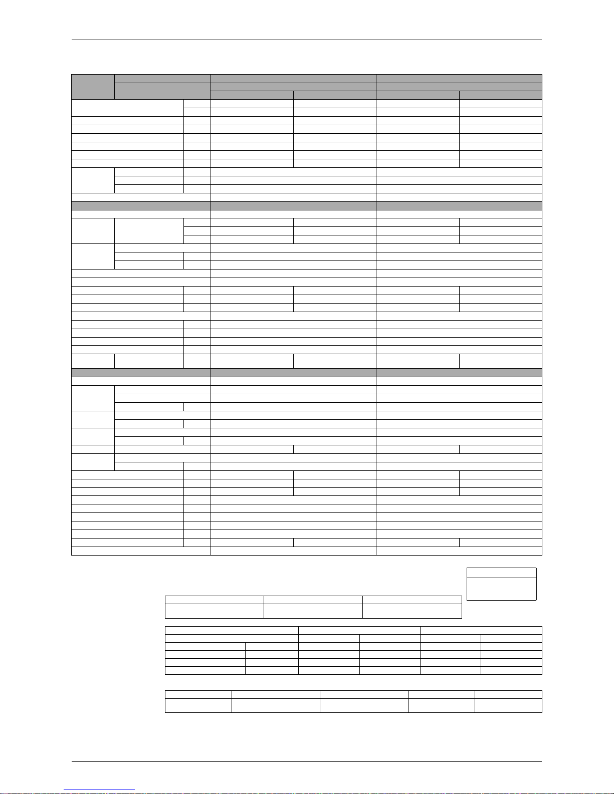
220V, 60Hz
Notes:
"
MAX. interunit piping length: 15m
"
MAX. interunit height difference: 15m
"
Amount of additional charge of refrigerant 20g/m for piping length exceeding 10m
"
The data are based on the conditions shows in the table below.
"
The data on the conditions (CNS3615):
(Conditions)
Models
Indoor Units FTX25JVET9 FTX35JVET9
Outdoor Units
RX25JVET9 RX35JVET9
Coolin g Heating Cooling Heating
Capacity (Min.~Max.)
kW 1.3~3.0 1.3~3.8 1.4~3.8 1.4~4.5
kcal/h 1,100~2,600 1,100~3,200 1,200~3,250 1,200~4,000
Moisture Removal L/h 1.2 — 1.9 —
Running Current (Min.~Max.) A 3.1~7.1 2.8~8.4 3.4~8.9 2.8~9.5
Power Consumption (Min.~Max.) W 470~1,300 300~1,300 520~1,650 280~1,500
Power Factor (Min.~Max.) % 68.9~83.2 48.7~70.3 69.5~84.3 45.5~71.8
COP (Min.~Max.) W/W 2.77~2.31 4.33~2.92 2.77~2.31 5.00~3.00
EER (Min.~Max.) kcal/h·W 2.34~2.00 3.67~2.46
Piping
Connections
Liquid mm
φ
6.4
φ
6.4
Gas mm
φ
9.5
φ
12.7
Drain mm
φ
18.0
φ
18.0
Heat Insulation Both Liquid and Gas Pipes Both Liquid and Gas Pipes
Indoor Units FTX25JVET9 FTX35JVET9
Front Panel Color Almond White Almond White
Air Flow Rate
m³/min
(cfm)
H 7.5 8.8 7.8 8.7
M 6.4 7.5 6.7 7.4
L 5.4 6.2 5.5 6.2
Fan
Type Cross Flow Fan Cross Flow Fan
Motor Output W 18 18
Speed Steps 5 Steps and Auto 5 Steps and Auto
Air Direction C o n tro l Right, Le ft, H o r izo n ta l and Downw ard Right, Left, Horizontal a n d D o wnward
Air Filter Remo v a l / Washable / Mildew P roof Removal / Washable / Milde w Proof
Running C u rre n t (Rated) A 0.21 0.21 0.21 0.21
Power Consumption (Rated) W 45 45 45 45
Power Factor % 97.4 97.4 97.4 97.4
Temperature Control Microcomputer Control Microcomputer Control
Dimensions (H×W×D) mm 273×784×185 273×784×185
Packaged Dimensions mm 834×325×258 834×325×258
Weight kg 7.5 7.5
Gross Weight kg 11 11
Operation
Sound
H/M/L dBA 37 / 34 / 30 37 / 33 / 30 38 / 35 / 32 38 / 35 / 31
Outdoor Units RX25JVET9 RX35JVET9
Casing Color Ivory White Ivory White
Compressor
Type H ermetically Sealed Rotary Type Hermetically Sealed Rotary Type
Model RC1X26BTNT RC1X26BTNT
Motor Output W 750 750
Refrigerant
Oil
Model SUNISO 4GSD.I. SUNISO 4GSD.I.
Charge L 0.4 0.4
Refrigerant
Model R22 R22
Charge kg 0.72 0.95
Air Flow Rate m³/min 29.0 25.5 27.5 23.0
Fan
Type Prope ller Prop eller
Motor Ou tp u t W 25 2 5
Running Current (Min.~Max.) A 2.89~6.89 2.59~8.19 3.19~8.69 2.59~9.29
Power Consumption (Min.~Max.) W 425~1,255 255~1,255 475~1,605 235~1,455
Power Factor (Min.~Max.) % 66.8~82.8 44.8~69.7 67.7~84.0 41.2~71.2
Starting Current A 6.1 7.6
Dimensions (H×W×D) mm 560×695×265 560×695×265
Packaged Dimensions (W×D×H) mm 797×310×599 797×310×599
Weight kg 31 32
Gross Weight kg 34 36
Operation Sound dBA 46 47 47 48
Drawing No. 3D029312 3D020460
Conversion Formulae
kcal/h=kW×860
Btu/h=kW×3414
cfm=m³/min×35.3
Cooling Heating Piping Length
Indoor ; 27°CDB/1 9 .5 °C WB
Outdoor ; 35°CDB/24°CWB
Indoor ; 21°CDB
Outdoor ; 7°CDB/6 °C WB
5m
Models FTX25JVET9 FTX35JVET9
(Rated) Cooling Heating Cooling Heating
Capacity kW (kcal/h) 2.0 (1,720) 3.4 (2,970) 2.6 (2,250) 4.2 (3,600)
Running Current A 3.8 5.5 5.0 6.9
Power Consumption W 755 1,020 990 1,340
COP (EER) W/W (kcal/h·W) 2.65 (2.27) 3.33 (2.91) 2.63 (2.27) 3.13 (2.69)
Standard Cooling Heating Piping Length Power Source
CNS3615
Indoor ; 27°CDB/19.5°CWB
Outdoor ; 35°CDB/24°CWB
Indoor ; 21°CDB
Outdoor ; 7°CDB/6 ° C WB
5m 60Hz 220V
Specifications Si04-115
10 Specification
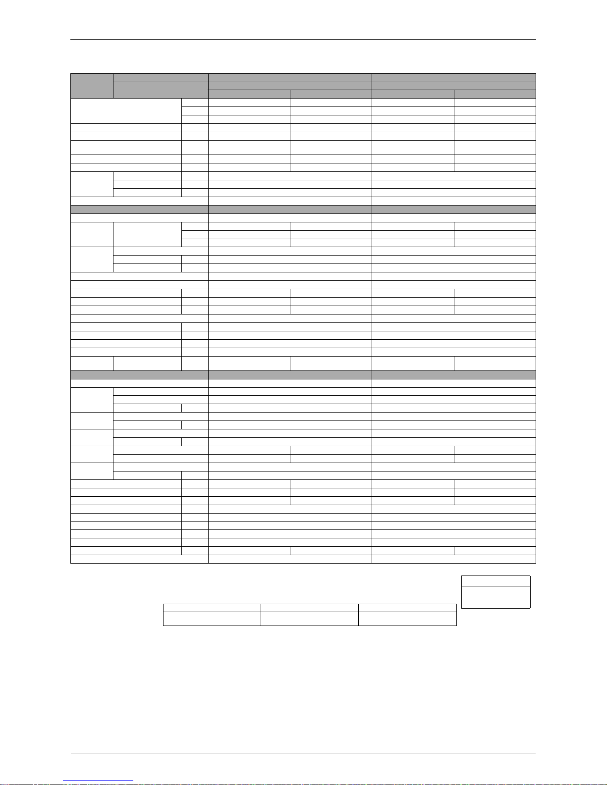
230V, 50Hz
Notes:
"
MAX. interunit piping length: 15m
"
MAX. interunit height difference: 15m
"
Amount of additional charge of refrigerant 20g/m for piping length exceeding 10m
"
The data are based on the conditions shows in the table below.
Models
Indoor Units FTX25JAV1NB FTX35JAV1NB
Outdoor Units
RX25JV1NB9 RX35JV1NB9
Coolin g Heating Cooling Heating
Capacity
Rated (M in .~ Max.)
kW 2.5 (1.3~3.0) 3.4 (1.3~4.0) 3.43 (1.4~3.8) 4.1 (1.4~5.1)
Btu/h 8,500 (4,400~10,300) 11,600 (4,400~13,600) 11,700 (4,800~13,000) 14,000 (4,800~17,600)
kcal/h 2,150 (1,100~2,600) 2,920 (1,100~3,440) 2,950 (1,200~3,300) 3,500 (1,200~4,400)
Moisture Removal L/h 1.2 — 1.9 —
Running Current (Rated) A 4.8 5.3 6.4 6.2
Power Consumption
Rated (M in .~ Max.)
W 980 (350~1,350) 1,130 (350~1,350) 1,430 (500~1,720) 1,375 (405~1,900)
Power Factor % 88.8 92.7 97.1 96.4
COP (Rated) W/W 2.55 3.01 2.4 2.98
Piping
Connections
Liquid mm
φ
6.4
φ
6.4
Gas mm
φ
9.5
φ
12.7
Drain mm
φ
18.0
φ
18.0
Heat Insulation Both Liquid and Gas Pipes Both Liquid and Gas Pipes
Indoor Units FTX25JAV1NB FTX35JAV1NB
Front Panel Color Almond White Almond White
Air Flow Rate
m³/min
(cfm)
H 7.1 (251) 8.4 (297) 7.4 (261) 8.4 (297)
M 5.9 (208) 7.0 (247) 6.0 (212) 7.1 (251)
L 4.6 (162) 5.7 (201) 4.7 (166) 5.9 (208)
Fan
Type Cross Flow Fan Cross Flow Fan
Motor Output W 18 18
Speed Steps 5 Steps and Auto 5 Steps and Auto
Air Direction C o n tro l Right, Le ft, H o r izo n ta l and Downw ard Right, Left, Horizontal a n d D o wnward
Air Filter Remo v a l / Washable / Mildew P roof Removal / Washable / Milde w Proof
Running Current (Rated) A 0.18 0.18 0.18 0.18
Power Consumption (Rated) W 40 40 40 40
Power Factor % 96.6 96.6 96.6 96.6
Temperature Control Microcomputer Control Microcomputer Control
Dimensions (H×W×D) mm 273×784×185 273×784×185
Packaged Dimensions mm 834×325×258 834×325×258
Weight kg 7.5 7.5
Gross Weight kg 11 11
Operation
Sound
H/M/L dBA 38 / 32 / 26 38 / 32 / 26 39 / 33 / 27 39 / 33 / 27
Outdoor Units RX25JV1NB9 RX35JV1N B9
Casing Color Ivory White Ivory White
Compressor
Type H ermetically Sealed Rotary Type Hermetically Sealed Rotary Type
Model RC1X26BTNT RC1X26BTNT
Motor Output W 750 750
Refrigerant
Oil
Model SUNISO 4GSD.I. SUNISO 4GSD.I.
Charge L 0.4 0.4
Refrigerant
Model R22 R22
Charge kg 0.72 0.95
Air Flow Rate
m³/min 29.0 25.5 27.5 23.5
cfm 1,024 900 970 830
Fan
Type Prope ller Prop eller
Motor Ou tp u t W 25 2 5
Running C u rre n t (Rated) A 4.62 5.12 6.22 6.02
Power Consumption (Rated) W 940 1,090 1,390 1,335
Power Factor % 88.5 92.6 97.2 96.4
Starting Current A 5.3 6.4
Dimensions (H×W×D) mm 560×695×265 560×695×265
Packaged Dimensions mm 797×310×599 797×310×599
Weight kg 33 35
Gross Weight kg 37 39
Operation Sound dBA 46 47 47 48
Drawing No. 3D 027497B 3D027498B
Conversion Formulae
kcal/h=kW×860
Btu/h=kW×3414
cfm=m³/min×35.3
Cooling Heating Piping Length
Indoor ; 27°CDB/19°CWB
Outdoor ; 35°CDB/24°CWB
Indoor ; 20°CDB
Outdoor ; 7°CDB/6 °C WB
7.5m

Si04-115
Printed Circuit Board Connector Wiring Diagram 11
Part 3
Part 3Part 3
Part 3
Printed Circuit Board
Printed Circuit BoardPrinted Circuit Board
Printed Circuit Board
Connector Wiring Diagram
Connector Wiring DiagramConnector Wiring Diagram
Connector Wiring Diagram
1.Printed Circuit Board Connector Wiring Diagram and Name................12
1.1 FTK25/35J Series, FTX25/35J Series....................................................12
1.2 RK25/35J Series, RX25/35J Series .......................................................15

Printed Circuit Board Connector Wiring Diagram and Name Si04-115
12 Printed Circuit Board Connector Wiring Diagram
1. Printed Circuit Board Connector Wiring Diagram
and Name
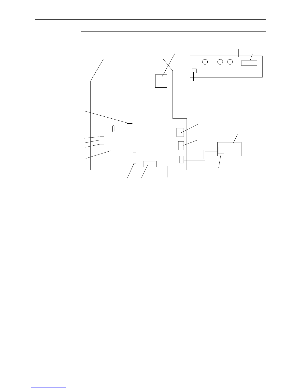
1.1 FTK25/35J Series, FTX25/35J Series
Printed circuit board (1) (Control PCB)
Printed circuit board (2) (Signal Receiver PCB)
Printed circuit board (3) (Intellige nt Eye S e n s or PCB)
Name of
connector
Note: Other designations
1) S1 Connector for fan motor
2) S6 Connector for swing motor (Horizontal Flap)
3) S7 Connector for fan motor
4) S21 Connector for centralized control to 5 rooms
5) S27, S36 Connector for control PCB
6) S26 Connector for signal receiver PCB
7) S32 Connector for room temp/Heat exchanger thermistor
8) S35 Connector for Intelligent Eye Sensor PCB
1) V1 V aristo r
2) JA ADDRESS SETTING JUMPER
JB Fan speed setting when compressor is OFF on thermostat.
JC Power failure recovery function.
∗
Refer to page 139 for more detail.
3) SW7 OPERATION SWITCH
4) LED1
(GRN)
LED for operation
5) LED2
(YLW)
LED for timer
6) LED3
(GRN)
LED for in te llige nt e ye
Si04-115 Printed Circuit Board Connector Wiring Diagram and Name
Printed Circuit Board Connector Wiring Diagram 13
Control PCB (1)
(R1895)
Control P C B (1)
S1
Signal receive P C B (2)
S27
GRN
GRN
YLW
LED1 LED2 LED3
SW7
S7
S6
Intelligent eye
sensor P C B (3)
S36
S35
S26
S32
S21
5V check
Jumper
JA
JB
JC
ground
12V check
Jumper
Printed Circuit Board Connector Wiring Diagram and Name Si04-115
14 Printed Circuit Board Connector Wiring Diagram
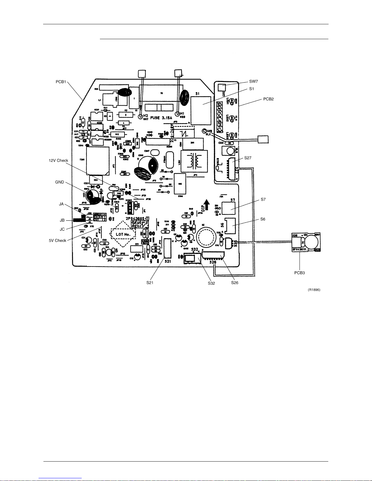
P.C.B (1) (Control P.C.B) Detail
Si04-115 Printed Circuit Board Connector Wiring Diagram and Name
Printed Circuit Board Connector Wiring Diagram 15
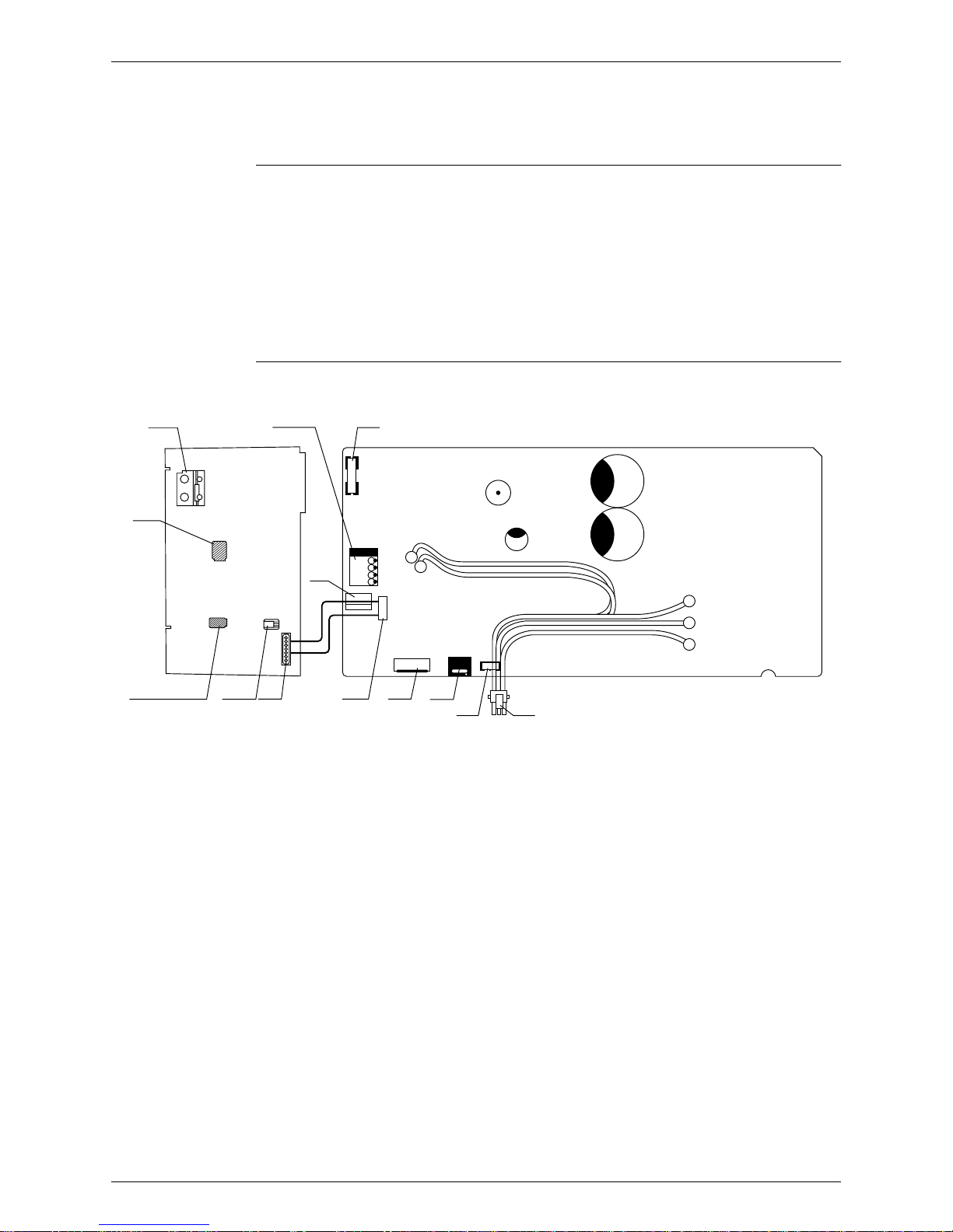
1.2 RK25/35J Series, RX25/35J Series
Printed circuit board (Main-PCB)
Printed circuit board (Mid-PCB )
Name of
connector
PCB
1) S10 Connector for Main-PCB
2) S11 Connector for Mid-PCB
3) S30 Connector for compressor motor (with internal thermostat & OL)
4) S70 Connector for fan motor
5) S80 Connector for 4 WAY VALVE COIL (RX25 · 35J Series only)
6) S90 Connector for THERMISTOR
7) SW1 NONE (Forced operation ON/OFF switch)
TFU
Mid-PCB Main-PCB
OL2
OL1
PARTS SIDE
W
V
U
FU1
V1
FU2
LED A
S10 S11 S70 S80
S90 S30
SW1
(Terrminal Side)
Service
Monitor
(R1992)
Printed Circuit Board Connector Wiring Diagram and Name Si04-115
16 Printed Circuit Board Connector Wiring Diagram
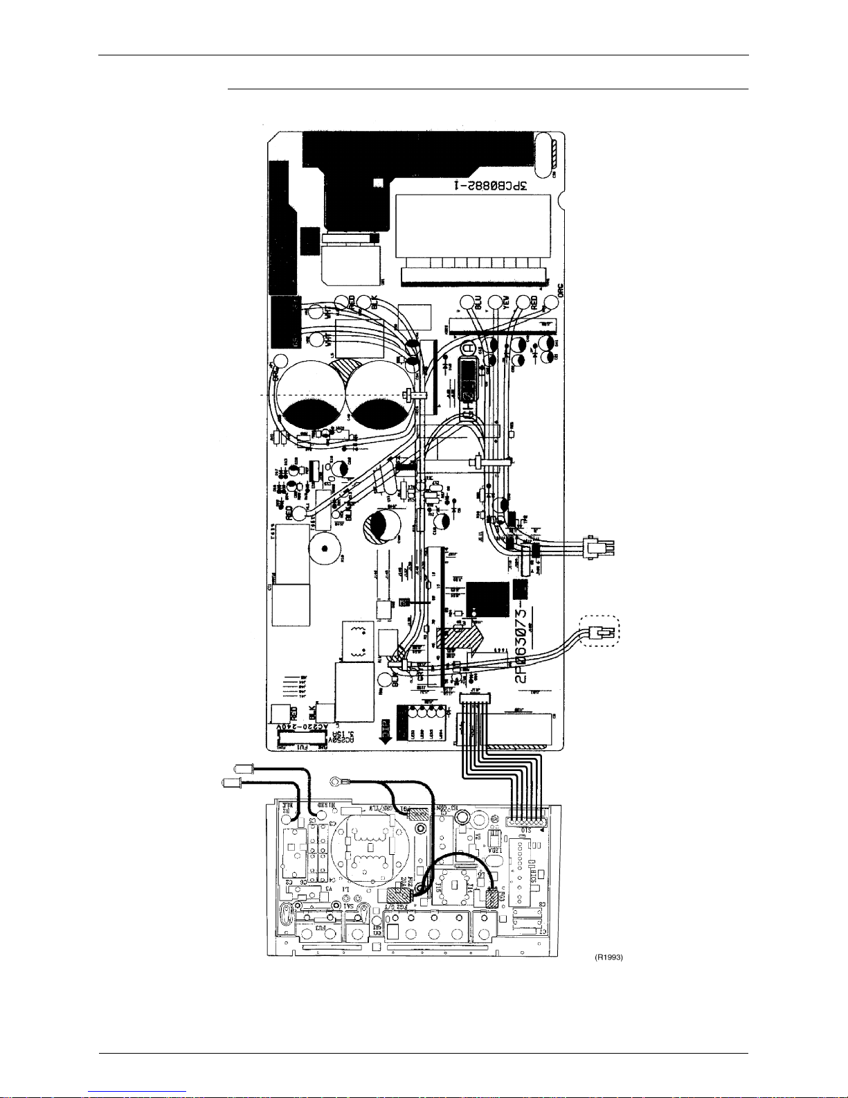
P.C.B Detail

Si04-115
Main Function 17
Part 4
Part 4Part 4
Part 4
Main Function
Main FunctionMain Function
Main Function
1.
General Functionality.......................................................................................18
1.1 Functions of Thermistors........................................................................18
1.2 Operating Modes....................................................................................20
1.3 Frequency Principle................................................................................21
1.4 Defrost Control .......................................................................................23
1.5 Forced Operation Mode .........................................................................24
1.6 Wide-angle Flaps, Diffuser, Louveres and Autoswing............................25
1.7 Fan Speed Control for Indoor Units........................................................26
1.8 Fan Speed Control for Outdoor Units.....................................................27
1.9 General Functions..................................................................................28
1.10 Intelligent Eye.........................................................................................30
1.11 Good Sleep Cooling Control...................................................................32
1.12 Automatic Operation...............................................................................33
1.13 Input Current Control..............................................................................34
1.14 Freeze Protection Function in Cooling ...................................................35
1.15 Peak-Cut Control Function.....................................................................36
1.16 Four-Way Valve Function Compensation...............................................37
1.17 Compressor Protection Function............................................................38
1.18 Wet Operation Protection.......................................................................39
1.19 Dew Condensation Sweating Prevention Function ................................40
General Functionality Si04-115
18 Main Function
1. General Functionality
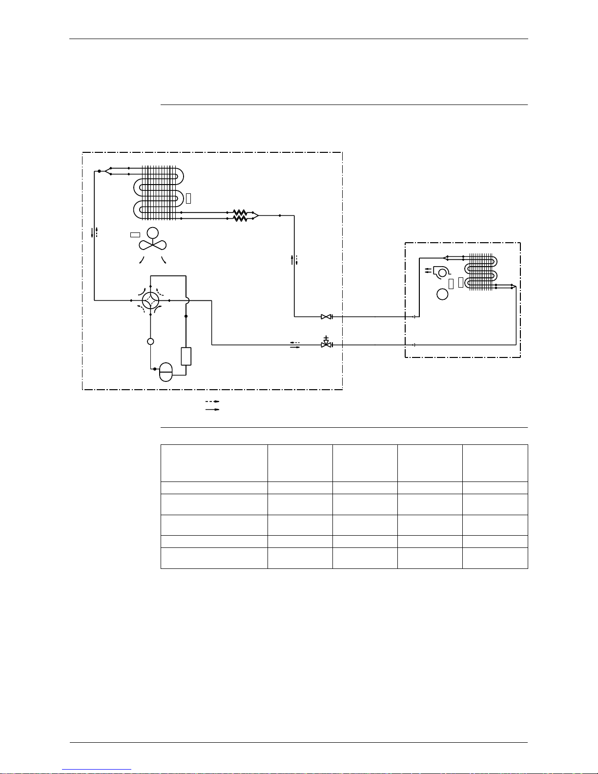
1.1 Functions of Thermistors
Location of
thermistors
The thermistors on the drawing below are used to control the system. This control secures a
proper cooling and prevents problems of the unit:
Frequency
control
The following table shows the thermistors that control the frequency:
with
#
: available functions and — : no available functions.
OUTDOOR UNIT
M
COOLING
HEATING
FIELD PIPING
FIELD PIPING
R1T
R2T
INDOOR UNIT
R1T
R2T
M
(R1899)
Controls
Outdoor heat
exchanger
thermistor
Outdoor
ambient
temperature
thermistor
Indoor ambient
temperature
thermistor
Indoor heat
exchanger
thermistor
Symbol R2T R1T R1T R2T
Freeze-up prevention.
Refer to page 19.
———#
Peak cut off. Refer to page
19.
———#
Defrost. Refer to page 23. ##— #
High pressure limitation in
heating. Refer to page 19.
# ——#
Si04-115 General Functionality
Main Function 19
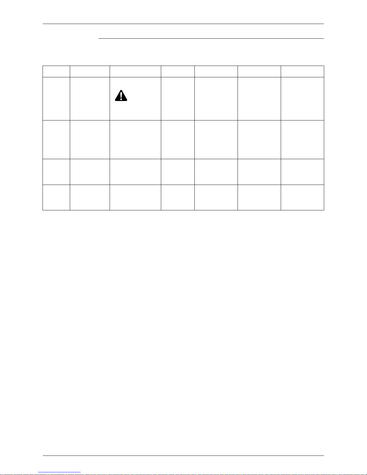
Frequency controlled functions
The following table shows the different functions, which are controlled by decreasing or
increasing the frequency:
Function
Sensor
Thermistor
Why? How? Set Reset Malfunction
Low
outdoor
temperatur
e control
outdoor ambient
thermistor (R1T)
To avoid condensation
in cooling mode.
This control
is not executed when
the unit is in forced
cooling mode or in test
mode.
By setting a
high frequency
limit.
T
outdoor ambient
<
18°C
T
outdoor ambient
>
25°C
—
High
pressure
limitation in
heating
"
outdoor
temperature
thermistor
(R1T)
"
indoor heat
exchanger
thermistor
(R2T)
To control the pressure. By setting a
high frequency
limit.
"
heating mode
"
T
outdoor
> 16 °C
"
T
indoor heat
exchanger
> 22 °C
"
compressor on
"
compressor stop
"
timer delay (70 s)
has passed
—
Freeze-up
prevention
indoor heat
exchanger
thermistor (R2T)
To prevent the freezing
up of the indoor unit in
cooling mode.
By setting a
high frequency
limit.
"
during cooling
"
0°C <
T
indoor heat
exchanger
< 8 °C
T
indoor heat exchanger
> 8 °C for 2
seconds
T
indoor heat exchanger
< 0 °C
(result: compressor
stop)
Peak cut off indoor heat
exchanger
thermistor (R2T)
To prevent an abnormal
high temperature on the
indoor heat exchanger
in heating mode.
By setting a
high frequency
limit.
"
during heating
"
50 °C <
T
indoor heat
exchanger
< 67 °C
T
indoor heat exchanger
< 50 °C for 2
seconds
T
indoor heat exchanger
> 67 °C
(result: compressor
stop)
General Functionality Si04-115
20 Main Function
1.2 Operating Modes
Modes There are two operating modes:
"
normal operating mode
"
forced operating mode.
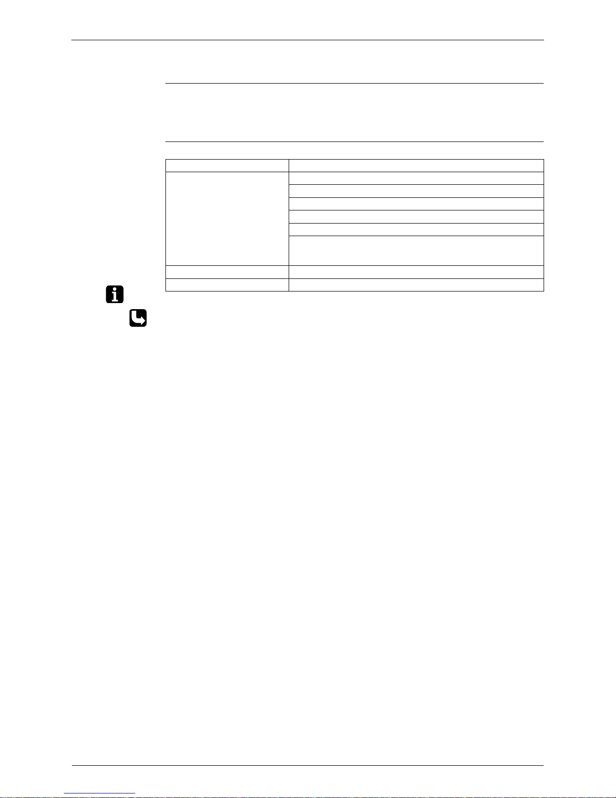
Overview The following table shows the different control modes of the Split inverter room air conditioners:
Note: The outdoor unit retains the operating mode, when the thermostat is switched off.
Refer to “Pre-heat operation” on page 28
Mode Item
Normal operating mode Auto (Heat pump only)
Cooling
Dry keep
Heating (Including Automatic defrost)
Fan (for Cooling only)
Stop mode:
" Pre-heat operation. Refer to “Pre-heat operation”.
" Stop
Test Operation Forced cooling / heating
Forced operating mode Forced cooling
Si04-115 General Functionality
Main Function 21
1.3 Frequency Principle
Main control
parameters
The compressor is frequency-controlled during normal operation. The target frequency is set by
the following 2 parameters coming from the operating indoor unit:
"
the load condition of the operating indoor unit
"
the differen ce between the room temp e ratu r e a n d th e s e t te mperature .
Additional
control
parameters
The targe t fr equency is adapted by additional parameters in the following cases:
"
frequency limits
"
initial settings
"
forced cooling/heating operation.
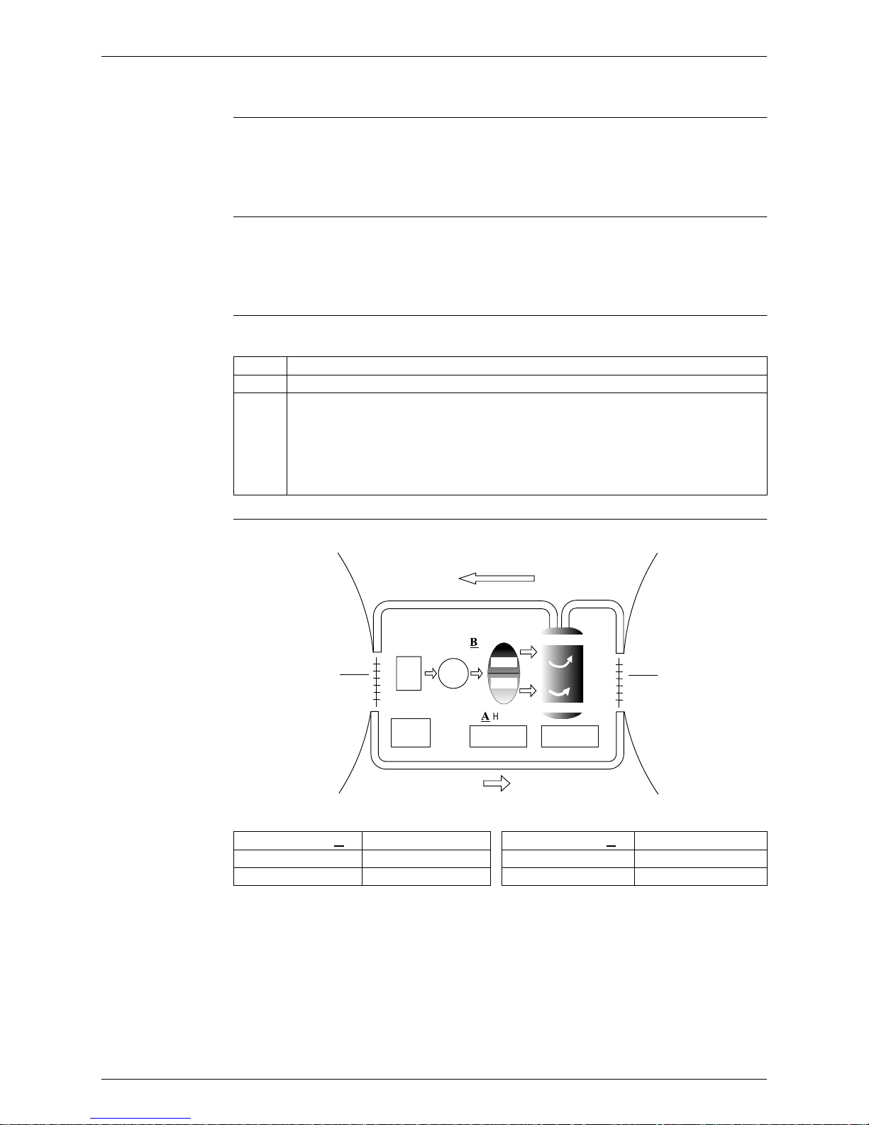
Inverter principle To regulate the capacity, a frequency control is needed. The inverter makes it possible to vary
the rotation speed of the compressor. The following table explains the conversion principle:
Drawing of
inverter
The following drawing shows a schematic view of the inverter principle:
Phase Description
1 The single phase power supply in AC is converted into DC.
2 The single phase power supply DC is converted into a three phase chopped DC voltage
with a variable frequency.
" When the frequency increases, the rotation speed of the compressor increases resulting
in an increased refrigerant circulation. This leads to a higher amount of the heat
exchange per unit.
" When the frequency decreases, the rotation speed of the compressor decreases
resulting in a decreased refrigerant circulation. This leads to a lower amount of the heat
exchange per unit.
Min. frequency
A
J type Max. frequency
B
J type
Cooling 34 Cooling 98
Heating 34 Heating 98
50 Hz
60 Hz
Refrigerant circulation rate (high)
Amount of heat
exchanged (large)
Amount of heat
exchanged (small)
AC
power
freq=
constant
max. freq.=
B
Hz
DC
power
Amount of heat
exchanged (large)
Amount of heat
exchanged (small)
high f
low f
min. freq.=
A
Hz
freq=variable
capacity=
variable
Refrigerant circulation rate (low)
high speed
low speed
(R1900)
 Loading...