

Daikin REYQ72TAYDU, REYQ120TAYDU, REYQ144TAYDU, REYQ168TAYDU, REYQ192TAYDU Service Manual
...
Service
Manual
SiUS371614E
REYQ72-456TAYDU
REYQ72-456TATJU
Heat Recovery 60 Hz
ED Reference
For items below, please refer to Engineering Data.
Item Model ED No. Page
VRV indoor unit
Specifications
Outdoor-air processing unit FXMQ-MF EDUS39-900A-F10 4
Energy recovery ventilator VAM-G EDUS711116A 2
Branch selector unit
VRV indoor unit
Option list
Outdoor-air processing unit FXMQ-MF EDUS39-900A-F10 32
Energy recovery ventilator VAM-G EDUS711116A 61
Branch selector unit
SiUS371614E
REYQ-TA Series
Heat Recovery
R-410A 60 Hz
FXFQ-T
FXFQ-P
FXZQ-M
FXUQ-P
FXEQ-P
FXDQ-M
FXMQ-PB
FXMQ-M
FXHQ-M
FXAQ-P
FXLQ-M, FXNQ-M
FXTQ-TA
Single
Multi
FXFQ-T
FXFQ-P
FXZQ-M
FXUQ-P
FXEQ-P
FXDQ-M
FXMQ-PB
FXMQ-M
FXHQ-M
FXAQ-P
FXLQ-M, FXNQ-M
FXTQ-TA
Single
Multi
EDUS391400-F14
EDUS391000-F1
EDUS391300-F9
EDUS391437-F15
EDUS391533-F16
EDUS39-600-F2
EDUS391503-F4
EDUS39-900A-F11
EDUS39-600-F5
EDUS391100-F6
EDUS391502-F7
FXTQ-TA Air Handling Unit
EDUS391434-B
EDUS391400-F14
EDUS391000-F1
EDUS391300-F9
EDUS391437-F15
EDUS391533-F16
EDUS39-600-F2
EDUS391503-F4
EDUS39-900A-F11
EDUS39-600-F5
EDUS391100-F6
EDUS391502-F7
FXTQ-TA Air Handling Unit
EDUS391434-B
2-4
2-3
2-3
3-4
3-5
3-4
3-5
3
3
2-3
4-7
4-5
11
27
43
40
48
36
27
30
43
25
32
43
28
47
23
53
i Table of Contents

SiUS371614E
1. Safety Cautions......................................................................................... vii
1.1 Warnings and Cautions Regarding Safety of Workers................................vii
1.2 Warnings and Cautions Regarding Safety of Users.....................................ix
2. Icons Used ................................................................................................ xii
Part 1 General Information ..............................................................1
1. Model Names of Indoor/Outdoor Units........................................................2
1.1 Indoor Unit.................................................................................................... 2
1.2 DOAS Unit.................................................................................................... 2
1.3 Outdoor Unit ................................................................................................. 2
1.4 Air Treatment Equipment ............................................................................. 4
1.5 Branch Selector Unit .................................................................................... 4
2. External Appearance...................................................................................5
2.1 Indoor Unit.................................................................................................... 5
2.2 DOAS Unit.................................................................................................... 6
2.3 Outdoor Unit ................................................................................................. 6
2.4 Air Treatment Equipment ............................................................................. 7
2.5 Branch Selector Unit .................................................................................... 7
3. Combination of Outdoor Units.....................................................................8
4. Capacity Range...........................................................................................9
4.1 Combination Ratio........................................................................................ 9
4.2 Outdoor Unit Combinations .......................................................................... 9
4.3 Limitation of Capacity Index for Heat Recovery ......................................... 10
Part 2 Refrigerant Circuit .............................................................. 11
1. Refrigerant Circuit .....................................................................................12
1.1 Outdoor Unit ............................................................................................... 12
1.2 Indoor Unit.................................................................................................. 16
1.3 Outdoor-Air Processing Unit....................................................................... 18
1.4 Branch Selector Unit .................................................................................. 19
2. Functional Parts Layout ............................................................................25
2.1 REYQ72TAYDU ......................................................................................... 25
2.2 REYQ96/120TAYDU .................................................................................. 26
2.3 REYQ144/168TAYDU ................................................................................ 27
2.4 REYQ72TATJU .......................................................................................... 28
2.5 REYQ96/120TATJU ................................................................................... 29
2.6 REYQ144/168TATJU ................................................................................. 30
3. Refrigerant Flow for Each Operation Mode...............................................31
3.1 REYQ72TAYDU, REYQ72TATJU.............................................................. 31
3.2 REYQ96-168TAYDU, REYQ96-168TATJU ............................................... 37
Part 3 Remote Controller ............................................................... 43
1. Applicable Models.....................................................................................44
2. Names and Functions ...............................................................................45
2.1 BRC1E73 ................................................................................................... 45
Table of Contents ii

SiUS371614E
2.2 Wireless Remote Controller ....................................................................... 47
3. MAIN/SUB Setting.....................................................................................48
3.1 BRC1E73 ................................................................................................... 48
3.2 Wireless Remote Controller ....................................................................... 49
4. Centralized Control Group No. Setting......................................................50
4.1 BRC1E73 ................................................................................................... 50
4.2 Wireless Remote Controller ....................................................................... 52
4.3 Group No. Setting Example........................................................................ 53
5. Service Mode ............................................................................................54
5.1 BRC1E73 ................................................................................................... 54
Part 4 Functions and Control......................................................... 56
1. Operation Flowchart (Outdoor Unit)..........................................................58
2. Stop Control ..............................................................................................59
2.1 Stop due to Error........................................................................................ 59
2.2 When System is in Stop Mode ................................................................... 59
2.3 Slave Unit Stops during Master Unit Operation.......................................... 59
3. Standby Control ........................................................................................60
3.1 Restart Standby.......................................................................................... 60
3.2 Crankcase Heater Control .......................................................................... 60
4. Startup Control..........................................................................................61
4.1 Startup Control in Cooling .......................................................................... 61
4.2 Startup Control in Heating .......................................................................... 62
5. Basic Control.............................................................................................63
5.1 Normal Operation ....................................................................................... 63
5.2 Compressor PI Control............................................................................... 64
5.3 Operation Priority and Rotation of Compressors........................................ 64
5.4 Compressor Step Control ........................................................................... 66
5.5 Electronic Expansion Valve PI Control....................................................... 69
5.6 Step Control of Outdoor Fans .................................................................... 70
5.7 Heat Exchanger Control............................................................................. 72
6. Protection Control .....................................................................................73
6.1 High Pressure Protection Control............................................................... 73
6.2 Low Pressure Protection Control................................................................ 75
6.3 Discharge Pipe Protection Control ............................................................. 76
6.4 Compressor Body Protection Control ......................................................... 77
6.5 Inverter Protection Control ......................................................................... 78
7. Special Control..........................................................................................80
7.1 Pump Down Residual Operation................................................................ 80
7.2 Oil Return Operation .................................................................................. 81
7.3 Defrost Operation ....................................................................................... 83
7.4 Cooling/Heating Mode Switching ............................................................... 84
8. Other Control.............................................................................................88
8.1 Backup Operation....................................................................................... 88
8.2 Demand Operation ..................................................................................... 88
8.3 Heating Operation Prohibition .................................................................... 88
iii Table of Contents

SiUS371614E
9. Outline of Control (Indoor Unit) .................................................................89
9.1 Operation Flowchart ................................................................................... 89
9.2 Set Temperature and Control Temperature ............................................... 91
9.3 Remote Controller Thermistor.................................................................... 93
9.4 Thermostat Control..................................................................................... 95
9.5 Drain Pump Control.................................................................................... 98
9.6 Control of Electronic Expansion Valve ..................................................... 100
9.7 Freeze-up Prevention............................................................................... 101
9.8 List of Swing Flap Operations .................................................................. 103
9.9 Hot Start Control (In Heating Only) .......................................................... 104
9.10 Louver Control for Preventing Ceiling Dirt................................................ 105
9.11 Heater Control (Except FXTQ-TA Models)............................................... 106
9.12 Heater Control (FXTQ-TA Models)........................................................... 107
9.13 3 Step Thermostat Processing (FXTQ-TA Models).................................. 110
9.14 Fan Control (Heater Residual) (FXTQ-TA Models).................................. 111
9.15 Interlocked with External Equipment (FXTQ-TA Models)......................... 111
Part 5 Field Settings .................................................................... 113
1. Field Setting from Remote Controller......................................................114
1.1 Wired Remote Controller.......................................................................... 114
1.2 Wireless Remote Controller ..................................................................... 116
1.3 Simplified Remote Controller.................................................................... 117
1.4 Setting Contents and Code No. for Indoor Units...................................... 118
2. Field Setting from Outdoor Unit...............................................................136
2.1 Accessing the BS Buttons on the Logic Board......................................... 136
2.2 Operating the BS Buttons and DIP Switches on the Logic Board ............ 137
2.3 Connecting of the Optional PC Configurator Cable to
the Outdoor Unit....................................................................................... 139
2.4 Monitoring Function and Field Settings .................................................... 140
2.5 Cool / Heat Mode Changeover................................................................. 149
2.6 Setting of Night-time Low Noise Operation and Demand Operation........ 150
3. Test Operation ........................................................................................155
3.1 Checks before Test Operation ................................................................. 155
3.2 Checkpoints.............................................................................................. 155
Part 6 Service Diagnosis.............................................................. 156
1. Symptom-based Troubleshooting ...........................................................159
1.1 Indoor Unit Overall ................................................................................... 159
1.2 With Optional Infrared Presence/Floor Sensor......................................... 162
2. Service Check Function ..........................................................................163
2.1 Wired Remote Controller.......................................................................... 163
2.2 Wireless Remote Controller ..................................................................... 165
2.3 Error Codes and Descriptions .................................................................. 167
2.4 Error Codes - Sub Codes ......................................................................... 169
3. Troubleshooting by Error Code...............................................................170
3.1 External Protection Device Abnormality................................................... 170
Table of Contents iv

SiUS371614E
3.2 Indoor Unit PCB Abnormality ................................................................... 172
3.3 Drain Level Control System Abnormality.................................................. 173
3.4 Fan Motor Lock, Overload........................................................................ 175
3.5 Indoor Fan Motor Abnormality.................................................................. 178
3.6 Overload/Overcurrent/Lock of Indoor Fan Motor...................................... 182
3.7 Blower Motor Not Running ....................................................................... 183
3.8 Indoor Fan Motor Status Abnormality....................................................... 184
3.9 Low Indoor Airflow.................................................................................... 185
3.10 Swing Flap Motor Abnormality ................................................................. 186
3.11 Power Supply Voltage Abnormality .......................................................... 188
3.12 Blower Motor Stops for Over/Under Voltage ............................................ 189
3.13 Electronic Expansion Valve Coil Abnormality, Dust Clogging .................. 190
3.14 Drain Level above Limit............................................................................ 191
3.15 Capacity Determination Device Abnormality ............................................ 192
3.16 Transmission Abnormality between Indoor Unit PCB and Fan PCB........ 193
3.17 Blower Motor Communication Error ......................................................... 195
3.18 Thermistor Abnormality ............................................................................ 196
3.19 Combination Error between Indoor Unit PCB and Fan PCB .................... 197
3.20 Blower Motor HP Mismatch ...................................................................... 198
3.21 Indoor Blower Does Not Have Required Parameters to Function............ 199
3.22 Remote Sensor Abnormality .................................................................... 200
3.23 Humidity Sensor System Abnormality ...................................................... 201
3.24 Infrared Presence/Floor Sensor Error ...................................................... 202
3.25 Remote Controller Thermistor Abnormality .............................................. 207
3.26 Outdoor Unit Main PCB Abnormality ........................................................ 208
3.27 Actuation of High Pressure Switch ........................................................... 209
3.28 Actuation of Low Pressure Sensor ........................................................... 211
3.29 Inverter Compressor Motor Lock .............................................................. 212
3.30 Compressor Damage Alarm ..................................................................... 214
3.31 Outdoor Fan Motor Abnormality ............................................................... 216
3.32 Electronic Expansion Valve Coil Abnormality........................................... 218
3.33 Discharge Pipe Temperature Abnormality ............................................... 219
3.34 Wet Alarm................................................................................................. 221
3.35 Refrigerant Overcharged.......................................................................... 222
3.36 Harness Abnormality (between Outdoor Unit Main PCB and
Inverter PCB)............................................................................................ 223
3.37 Outdoor Fan Motor Signal Abnormality .................................................... 224
3.38 Thermistor Abnormality ............................................................................ 225
3.39 High Pressure Sensor Abnormality .......................................................... 227
3.40 Low Pressure Sensor Abnormality........................................................... 228
3.41 Inverter PCB Abnormality......................................................................... 229
3.42 Reactor Temperature Rise Abnormality ................................................... 231
3.43 Inverter Radiation Fin Temperature Rise Abnormality ............................. 232
3.44 Inverter Compressor Instantaneous Overcurrent ..................................... 233
3.45 Inverter Compressor Overcurrent............................................................. 235
3.46 Inverter Compressor Startup Abnormality ................................................ 237
3.47 Transmission Error between Inverter PCB and
Outdoor Unit Main PCB............................................................................ 240
v Table of Contents

SiUS371614E
3.48 Power Supply Voltage Imbalance ............................................................ 242
3.49 Reactor Temperature Abnormality ........................................................... 244
3.50 Inverter Radiation Fin Temperature Abnormality ..................................... 245
3.51 Field Setting after Replacing Outdoor Unit Main PCB Abnormality or
Combination of PCB Abnormality............................................................. 246
3.52 Refrigerant Shortage ................................................................................ 247
3.53 Reverse Phase, Open Phase ................................................................... 248
3.54 Power Supply Insufficient or Instantaneous Abnormality ......................... 249
3.55 Check Operation not Executed ................................................................ 251
3.56 Transmission Error between Indoor Units and Outdoor Units.................. 252
3.57 Transmission Error between Remote Controller and Indoor Unit............. 255
3.58 Transmission Error between Outdoor Units ............................................. 256
3.59 Transmission Error between Main and Sub Remote Controllers ............. 262
3.60 Transmission Error between Indoor Unit and
Outdoor Unit in the Same System ............................................................ 263
3.61 Improper Combination of Indoor Unit and Outdoor Unit,
Indoor Unit and Remote Controller........................................................... 264
3.62 Incorrect Electric Heater Capacity Setting................................................ 268
3.63 Address Duplication of Centralized Controller.......................................... 269
3.64 Transmission Error between Centralized Controller and Indoor Unit....... 270
3.65 System not Set yet ................................................................................... 272
3.66 System Abnormality, Refrigerant System Address Undefined ................. 273
4. Check ......................................................................................................275
4.1 High Pressure Check ............................................................................... 275
4.2 Low Pressure Check ................................................................................ 276
4.3 Superheat Operation Check..................................................................... 277
4.4 Power Transistor Check ........................................................................... 278
4.5 Refrigerant Overcharge Check................................................................. 279
4.6 Refrigerant Shortage Check..................................................................... 280
4.7 Vacuuming and Dehydration Procedure .................................................. 281
4.8 Thermistor Check ..................................................................................... 282
4.9 Pressure Sensor Check ........................................................................... 285
4.10 Broken Wire Check of the Relay Wires .................................................... 286
4.11 Fan Motor Connector Check (Power Supply Cable) ................................ 287
4.12 Fan Motor Connector Check (Signal Cable) ............................................ 287
4.13 Electronic Expansion Valve Coil Check ................................................... 288
Part 7 Appendix............................................................................ 289
1. Wiring Diagrams......................................................................................290
1.1 Outdoor Unit ............................................................................................. 290
1.2 Indoor Unit................................................................................................ 296
1.3 Air Treatment Equipment ......................................................................... 303
1.4 Branch Selector Unit ................................................................................ 306
Table of Contents vi
Safety Cautions SiUS371614E
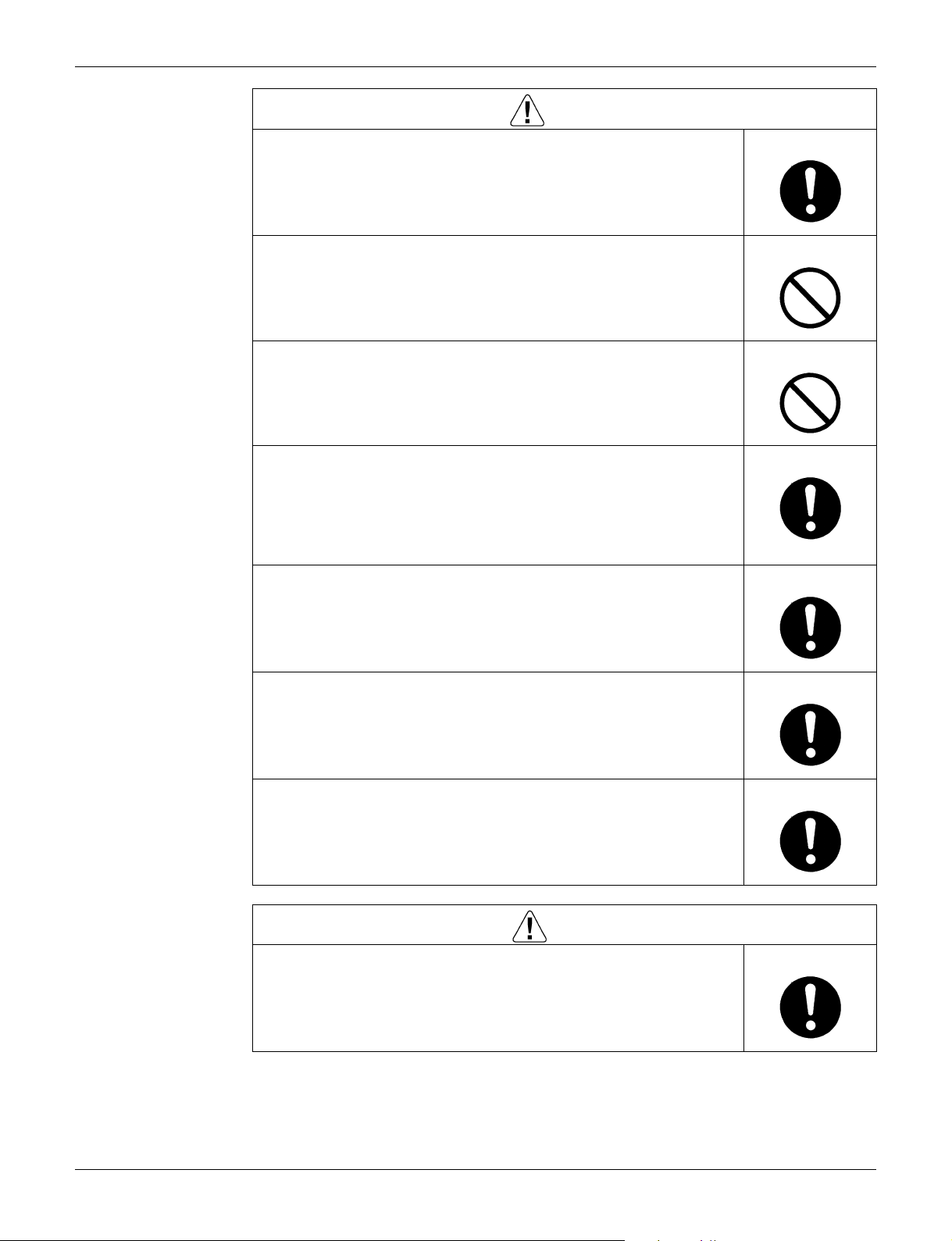
1. Safety Cautions
Be sure to read the following safety cautions before conducting repair work.
After the repair work is complete, be sure to conduct a test operation to ensure that the equipment
operates normally, and explain the cautions for operating the product to the customer.
Caution Items The caution items are classified into Warning and Caution. The Warning items are
especially important since death or serious injury can result if they are not followed closely. The
Caution items can also lead to serious accidents under some conditions if they are not
followed. Therefore, be sure to observe all the safety caution items described below.
Pictograms This symbol indicates the item for which caution must be exercised.
The pictogram shows the item to which attention must be paid.
This symbol indicates the prohibited action.
The prohibited item or action is shown in the illustration or near the symbol.
This symbol indicates the action that must be taken, or the instruction.
The instruction is shown in the illustration or near the symbol.
1.1 Warnings and Cautions Regarding Safety of Workers
Warning
Do not store the equipment in a room with fire sources (e.g. naked flames,
gas appliances, electric heaters).
Be sure to disconnect the power cable from the socket before
disassembling equipment for repair.
Working on equipment that is connected to the power supply may cause an
electrical shock.
If it is necessary to supply power to the equipment to conduct the repair or
inspecting the circuits, do not touch any electrically charged sections of the
equipment.
If refrigerant gas is discharged during repair work, do not touch the
discharged refrigerant gas.
Refrigerant gas may cause frostbite.
When disconnecting the suction or discharge pipe of the compressor at
the welded section, evacuate the refrigerant gas completely at a wellventilated place first.
If there is gas remaining inside the compressor, the refrigerant gas or
refrigerating machine oil discharges when the pipe is disconnected, and it may
cause injury.
If refrigerant gas leaks during repair work, ventilate the area.
Refrigerant gas may generate toxic gases when it contacts flames.
vii
Be sure to discharge the capacitor completely before conducting repair
work.
The step-up capacitor supplies high-voltage electricity to the electrical
components of the outdoor unit.
A charged capacitor may cause an electrical shock.

SiUS371614E Safety Cautions
Warning
Do not turn the air conditioner on or off by plugging in or unplugging the
power cable.
Plugging or unplugging the power cable to operate the equipment may cause
an electrical shock or fire.
Be sure to wear a safety helmet, gloves, and a safety belt when working
in a high place (more than 2 m (6.5 ft)).
Insufficient safety measures may cause a fall.
In case of R-32 and R-410A refrigerant models, be sure to use pipes, flare
nuts and tools intended for exclusive use with R-32 and R-410A
refrigerant.
The use of materials for R-22 refrigerant models may cause a serious accident,
such as damage to the refrigerant cycle or equipment failure.
Do not mix air or gas other than the specified refrigerant (R-32, R-410A,
R-22) in the refrigerant system.
If air enters the refrigerating system, excessively high pressure results, causing
equipment damage and injury.
Caution
Do not repair electrical components with wet hands.
Working on the equipment with wet hands may cause an electrical shock.
Do not clean the air conditioner with water.
Washing the unit with water may cause an electrical shock.
Be sure to provide an earth/grounding when repairing the equipment in a
humid or wet place, to avoid electrical shocks.
Be sure to turn off the power switch and unplug the power cable when
cleaning the equipment.
The internal fan rotates at a high speed, and may cause injury.
Be sure to conduct repair work with appropriate tools.
The use of inappropriate tools may cause injury.
viii
Safety Cautions SiUS371614E
Caution
Be sure to check that the refrigerating cycle section has cooled down
enough before conducting repair work.
Working on the unit when the refrigerating cycle section is hot may cause
burns.
Conduct welding work in a well-ventilated place.
Using a welder in an enclosed room may cause oxygen deficiency.
1.2 Warnings and Cautions Regarding Safety of Users
Warning
Do not store the equipment in a room with fire sources (e.g. naked flames,
gas appliances, electric heaters).
Be sure to use parts listed in the service parts list of the applicable model
and appropriate tools to conduct repair work. Never attempt to modify the
equipment.
The use of inappropriate parts or tools may cause an electrical shock,
excessive heat generation or fire.
If the power cable and lead wires are scratched or have deteriorated, be
sure to replace them.
Damaged cable and wires may cause an electrical shock, excessive heat
generation or fire.
Do not use a joined power cable or extension cable, or share the same
power outlet with other electrical appliances, since it may cause an
electrical shock, excessive heat generation or fire.
Be sure to use an exclusive power circuit for the equipment, and follow
the local technical standards related to the electrical equipment, the
internal wiring regulations, and the instruction manual for installation
when conducting electrical work.
Insufficient power circuit capacity and improper electrical work may cause an
electrical shock or fire.
Be sure to use the specified cable for wiring between the indoor and
outdoor units.
Make the connections securely and route the cable properly so that there is no
force pulling the cable at the connection terminals.
Improper connections may cause excessive heat generation or fire.
ix
SiUS371614E Safety Cautions
Warning
When wiring between the indoor and outdoor units, make sure that the
terminal cover does not lift off or dismount because of the cable.
If the cover is not mounted properly, the terminal connection section may cause
an electrical shock, excessive heat generation or fire.
Do not damage or modify the power cable.
Damaged or modified power cables may cause an electrical shock or fire.
Placing heavy items on the power cable, or heating or pulling the power cable
may damage it.
Do not mix air or gas other than the specified refrigerant (R-32, R-410A,
R-22) in the refrigerant system.
If air enters the refrigerating system, excessively high pressure results, causing
equipment damage and injury.
If the refrigerant gas leaks, be sure to locate the leakage and repair it
before charging the refrigerant. After charging the refrigerant, make sure
that there is no leakage.
If the leakage cannot be located and the repair work must be stopped, be sure
to pump-down, and close the service valve, to prevent refrigerant gas from
leaking into the room. Refrigerant gas itself is harmless, but it may generate
toxic gases when it contacts flames, such as those from fan type and other
heaters, stoves and ranges.
When relocating the equipment, make sure that the new installation site
has sufficient strength to withstand the weight of the equipment.
If the installation site does not have sufficient strength or if the installation work
is not conducted securely, the equipment may fall and cause injury.
Check to make sure that the power cable plug is not dirty or loose, then
insert the plug into a power outlet securely.
If the plug is dusty or has a loose connection, it may cause an electrical shock
or fire.
When replacing the coin battery in the remote controller, be sure to
dispose of the old battery to prevent children from swallowing it.
If a child swallows the coin battery, see a doctor immediately.
Caution
Installation of a leakage breaker is necessary in some cases depending
on the conditions of the installation site, to prevent electrical shocks.
x
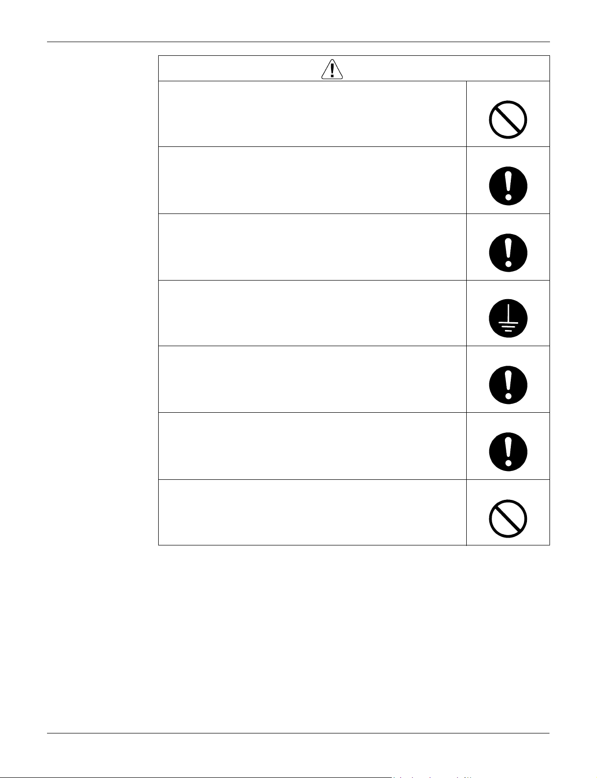
Safety Cautions SiUS371614E
Caution
Do not install the equipment in a place where there is a possibility of
combustible gas leaks.
If combustible gas leaks and remains around the unit, it may cause a fire.
Check to see if parts and wires are mounted and connected properly, and
if the connections at the soldered or crimped terminals are secure.
Improper installation and connections may cause excessive heat generation,
fire or an electrical shock.
If the installation platform or frame has corroded, replace it.
A corroded installation platform or frame may cause the unit to fall, resulting in
injury.
Check the earth/grounding, and repair it if the equipment is not properly
earthed/grounded.
Improper earth/grounding may cause an electrical shock.
Be sure to measure insulation resistance after the repair, and make sure
that the resistance is 1 MΩ or higher.
Faulty insulation may cause an electrical shock.
Be sure to check the drainage of the indoor unit after the repair.
Faulty drainage may cause water to enter the room and wet the furniture and
floor.
Do not tilt the unit when removing it.
The water inside the unit may spill and wet the furniture and floor.
xi
SiUS371614E Icons Used
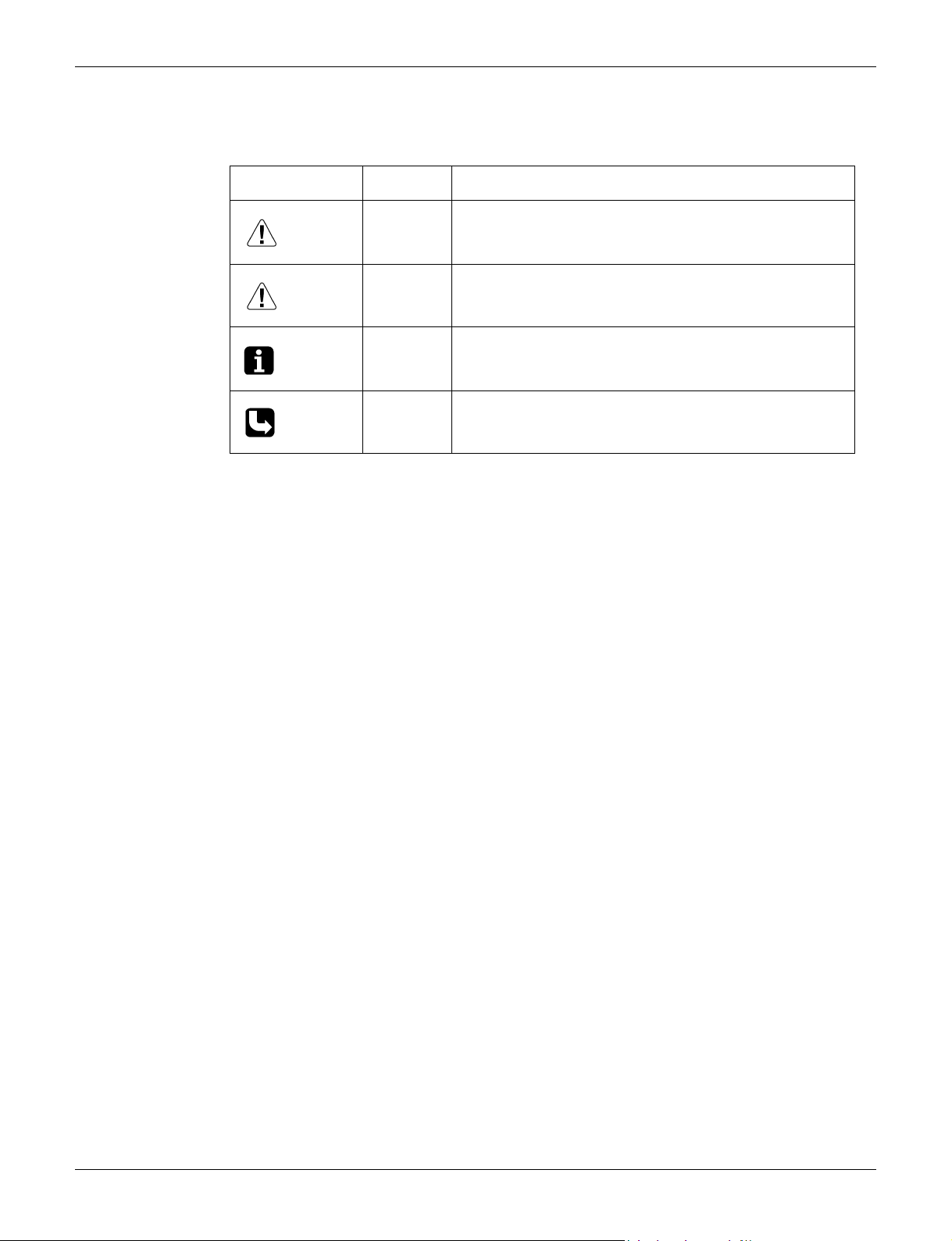
2. Icons Used
The following icons are used to attract the attention of the reader to specific information.
Icon Type of
Information
Warning A warning is used when there is danger of personal injury.
Warning
Caution A caution is used when there is danger that the reader, through
Caution
Note A note provides information that is not indispensable, but may
Note:
Reference A reference guides the reader to other places in this binder or in
Description
incorrect manipulation, may damage equipment, lose data, get
an unexpected result or have to restart (part of) a procedure.
nevertheless be valuable to the reader, such as tips and tricks.
this manual, where he/she will find additional information on a
specific topic.
xii

SiUS371614E
Part 1
General Information
1. Model Names of Indoor/Outdoor Units........................................................2
1.1 Indoor Unit.................................................................................................... 2
1.2 DOAS Unit.................................................................................................... 2
1.3 Outdoor Unit ................................................................................................. 2
1.4 Air Treatment Equipment ............................................................................. 4
1.5 Branch Selector Unit .................................................................................... 4
2. External Appearance...................................................................................5
2.1 Indoor Unit.................................................................................................... 5
2.2 DOAS Unit.................................................................................................... 6
2.3 Outdoor Unit ................................................................................................. 6
2.4 Air Treatment Equipment ............................................................................. 7
2.5 Branch Selector Unit .................................................................................... 7
3. Combination of Outdoor Units.....................................................................8
4. Capacity Range...........................................................................................9
4.1 Combination Ratio........................................................................................ 9
4.2 Outdoor Unit Combinations .......................................................................... 9
4.3 Limitation of Capacity Index for Heat Recovery ......................................... 10
1 General Information
SiUS371614E Model Names of Indoor/Outdoor Units
1. Model Names of Indoor/Outdoor Units
1.1 Indoor Unit
Capacity Range (ton) 0.6 0.8 1 1.25 1.5 2 2.5 3 3.5 4 4.5 5 6 8 Power
Capacity Index 7.5 9.5 12 15 18 20 24 30 36 42 48 54 60 72 96
Ceiling Mounted Cassette
(Round Flow with Sensing) Type
Ceiling Mounted Cassette
(Round Flow) Type
4 Way Ceiling Mounted
Cassette (2'×2') Type
4-Way Blow Ceiling-Suspended Type
One Way Blow Cassette TypeFXEQ07P09P12P15P18P—24P————————
Slim Ceiling Mounted Duct Type
Ceiling Mounted Duct Type
(Middle and High Static Pressure)
Ceiling Mounted Duct Type FXMQ —————————————72M96M
Ceiling Suspended Type FXHQ — — 12M — — — 24M — 36M ——————
Wall Mounted Type FXAQ 07P 09P 12P — 18P — 24P ————————
Floor Standing Type FXLQ
Concealed Floor Standing Type
Air Handling Unit FXTQ —
FXFQ07T09T12T15T18T—24T30T36T—48T————
FXFQ—09P12P—18P—24P30P36P—48P————
FXZQ07M09M12M15M18M—————————— VJU9
FXUQ—————18P24P30P36P——————
FXDQ07M09M12M—18M—24M————————
FXMQ
07PB 09PB 12PB 15PB 18PB
07M—————————————— VJU9
—09M12M—18M—24M———————— VJU
07M—————————————— VJU9
FXNQ
—09M12M—18M—24M———————— VJU
09TA 12TA
—
18TA
—
24PB 30PB 36PB
—
24TA 30TA 36TA 42TA 48TA 54TA 60TA
—
48PB 54PB
———
——VJUA(D)
Supply,
Standard
VJU
VJU
VJ : 1 phase, 208/230 V, 60 Hz
) : Standard Symbol
U(VJU
1.2 DOAS Unit
Airflow volume (cfm) 1000 2000 3000
DOAS unit DVS DVSV05 DVSV10 DVSV12
1.3 Outdoor Unit
Capacity Range (ton) 6 8 10 12 14 16 18 20 22
Capacity Index 72 96 120 144 168 192 216 240 264
Heat Recovery
Capacity Range (ton) 24 26 28 30 32 34 36 38
Capacity Index 288 312 336 360 384 408 432 456
Heat Recovery
YD : 3 phase, 460 V, 60 Hz
TJ : 3 phase, 208/230 V, 60 Hz
) : Standard Symbol
U(TJU
460 V REYQ- 72TA 96TA 120TA 144TA 168TA 192TA 216TA 240TA 264TA YDU
208/230 V
460 V REYQ- 288TA 312TA 336TA 360TA 384TA 408TA 432TA 456TA YDU
208/230 V
REYQ- 72TA 96TA 120TA 144TA 168TA 192TA 216TA 240TA 264TA TJU
REYQ- 288TA 312TA 336TA 360TA 384TA 408TA 432TA 456TA TJU
Power Supply,
Standard
Power Supply,
Standard
General Information 2
Model Names of Indoor/Outdoor Units SiUS371614E
1.3.1 Combination of Outdoor Units (Heat Recovery 460 V)
REYQ-TAYDU
Model name REYQ72TAYDU REYQ96TAYDU REYQ120TAYDU REYQ144TAYDU REYQ168TAYDU
Outdoor unit 1 REYQ72TAYDU REYQ96TAYDU REYQ120TAYDU REYQ144TAYDU REYQ168TAYDU
Model name REYQ192TAYDU REYQ216TAYDU REYQ240TAYDU REYQ264TAYDU REYQ288TAYDU
Outdoor unit 1 REYQ72TAYDU REYQ96TAYDU REYQ96TAYDU REYQ120TAYDU REYQ144TAYDU
Outdoor unit 2 REYQ120TAYDU REYQ120TAYDU REYQ144TAYDU REYQ144TAYDU REYQ144TAYDU
Model name REYQ312TAYDU REYQ336TAYDU REYQ360TAYDU REYQ384TAYDU REYQ408TAYDU
Outdoor unit 1 REYQ144TAYDU REYQ168TAYDU REYQ120TAYDU REYQ96TAYDU REYQ96TAYDU
Outdoor unit 2 REYQ168TAYDU REYQ168TAYDU REYQ120TAYDU REYQ120TAYDU REYQ144TAYDU
Outdoor unit 3 — — REYQ120TAYDU REYQ168TAYDU REYQ168TAYDU
Model name REYQ432TAYDU REYQ456TAYDU
Outdoor unit 1 REYQ144TAYDU REYQ144TAYDU
Outdoor unit 2 REYQ144TAYDU REYQ144TAYDU
Outdoor unit 3 REYQ144TAYDU REYQ168TAYDU
1.3.2 Combination of Outdoor Units (Heat Recovery 208/230 V)
REYQ-TATJU
Model name REYQ72TATJU REYQ96TATJU REYQ120TATJU REYQ144TATJU REYQ168TATJU
Outdoor unit 1 REYQ72TATJU REYQ96TATJU REYQ120TATJU REYQ144TATJU REYQ168TATJU
Model name REYQ192TATJU REYQ216TATJU REYQ240TATJU REYQ264TATJU REYQ288TATJU
Outdoor unit 1 REYQ72TATJU REYQ96TATJU REYQ96TATJU REYQ120TATJU REYQ144TATJU
Outdoor unit 2 REYQ120TATJU REYQ120TATJU REYQ144TATJU REYQ144TATJU REYQ144TATJU
Model name REYQ312TATJU REYQ336TATJU REYQ360TATJU REYQ384TATJU REYQ408TATJU
Outdoor unit 1 REYQ144TATJU REYQ168TATJU REYQ120TATJU REYQ96TATJU REYQ96TATJU
Outdoor unit 2 REYQ168TATJU REYQ168TATJU REYQ120TATJU REYQ120TATJU REYQ144TATJU
Outdoor unit 3 — — REYQ120TATJU REYQ168TATJU REYQ168TATJU
Model name REYQ432TATJU REYQ456TATJU
Outdoor unit 1 REYQ144TATJU REYQ144TATJU
Outdoor unit 2 REYQ144TATJU REYQ144TATJU
Outdoor unit 3 REYQ144TATJU REYQ168TATJU
3 General Information
SiUS371614E Model Names of Indoor/Outdoor Units
1.4 Air Treatment Equipment
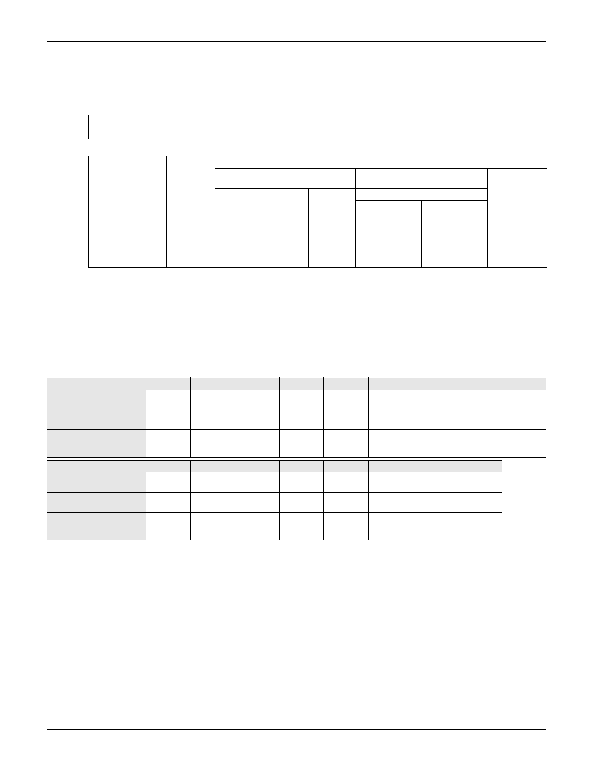
Outdoor Air Processing Unit
Series Model Name Power Supply, Standard
FXMQ 48MF 72MF 96MF VJU
Energy Recovery Ventilator (VAM series)
Series Model Name Power Supply, Standard
VAM 300G 470G 600G 1200G VJU
VJ : 1 phase, 208/230 V, 60 Hz
) : Standard Symbol
U(VJU
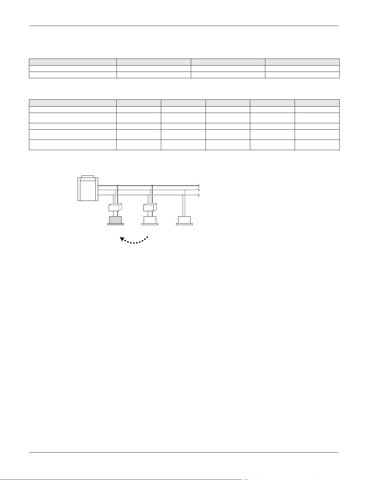
1.5 Branch Selector Unit
Single Branch Selector Unit for Heat Recovery
Series Model Name Power Supply, Standard
Heat Recovery BSQ 36T 60T 96T VJ
Note: No interchangeability with BSVQ36/60/96PVJU.
VJ: 1 phase, 208/230 V, 60 Hz
Multi Branch Selector Unit for Heat Recovery
Series Model Name Power Supply, Standard
Heat Recovery BS 4Q54T 6Q54T 8Q54T 10Q54T 12Q54T VJ
Note: No interchangeability with BSV4/6Q36PVJU.
VJ: 1 phase, 208/230 V, 60 Hz
General Information 4
External Appearance SiUS371614E
2. External Appearance
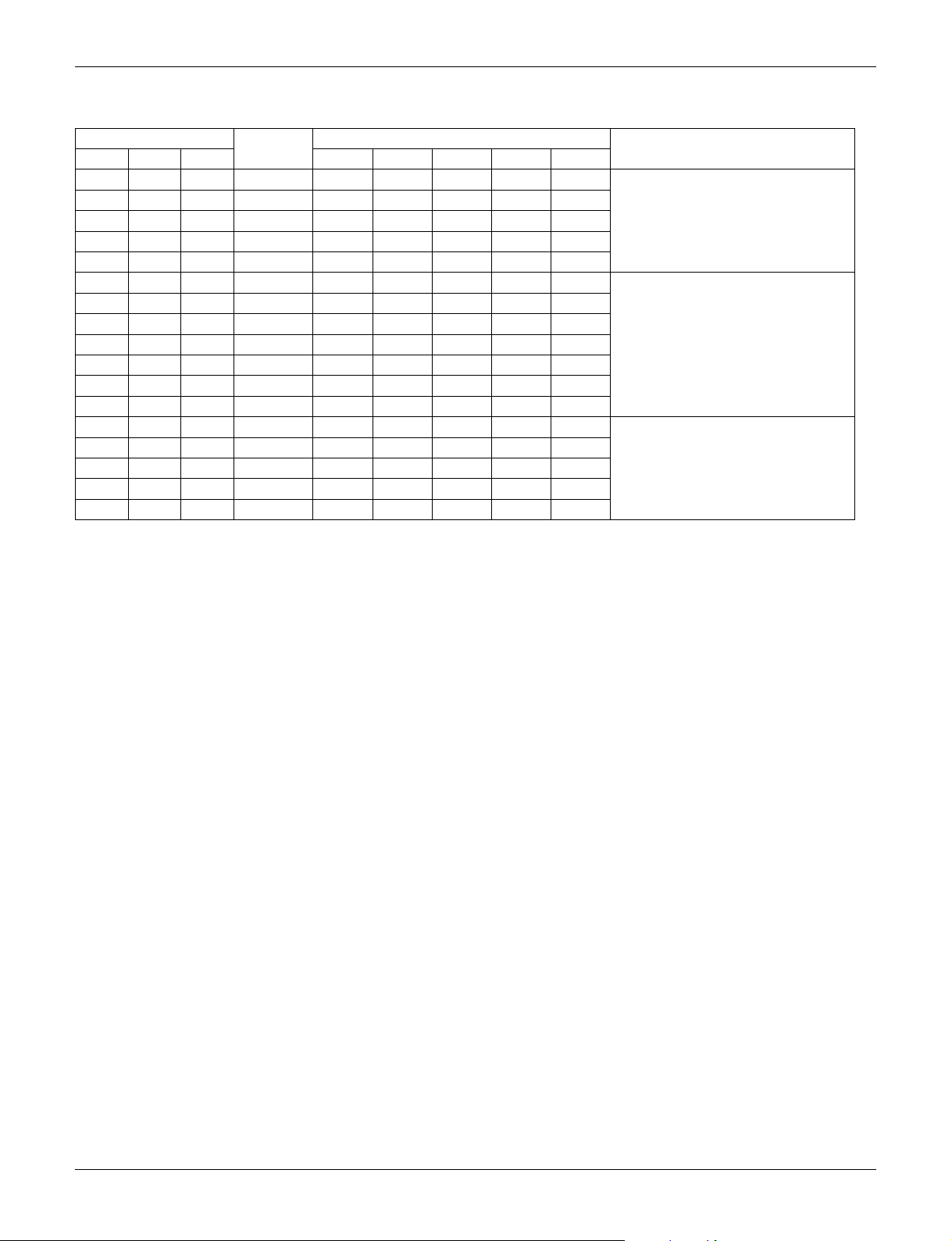
2.1 Indoor Unit
Ceiling mounted cassette (Round flow with sensing) type
FXFQ-T
Shown with BYCQ125B-W1
Ceiling mounted cassette (Round flow) type
FXFQ-P
Shown with BYCP125K-W1
4 way ceiling mounted cassette (2’×2’) type
FXZQ-M
Shown with BYFQ60B8W1U
4-way blow ceiling-suspended type
FXUQ-P
Ceiling mounted duct type
FXMQ-M
Ceiling suspended type
FXHQ-M
Wall mounted type
FXAQ-P
Floor standing type
FXLQ-M
One way blow cassette type
FXEQ-P
Slim ceiling mounted duct type
FXDQ-M
Ceiling mounted duct type (Middle and high static pressure)
FXMQ-PB
Concealed floor standing type
FXNQ-M
Air handling unit
FXTQ-TA
5 General Information
SiUS371614E External Appearance
2.2 DOAS Unit
DVSV05/10/12
2.3 Outdoor Unit
Single Outdoor Unit
REYQ72TAYDU
REYQ72TATJU
REYQ96/120/144/168TAYDU
REYQ96/120/144/168TATJU
Double Outdoor Unit
REYQ192TAYDU
REYQ192TATJU
General Information 6
REYQ216/240/264/288/312/336TAYDU
REYQ216/240/264/288/312/336TATJU
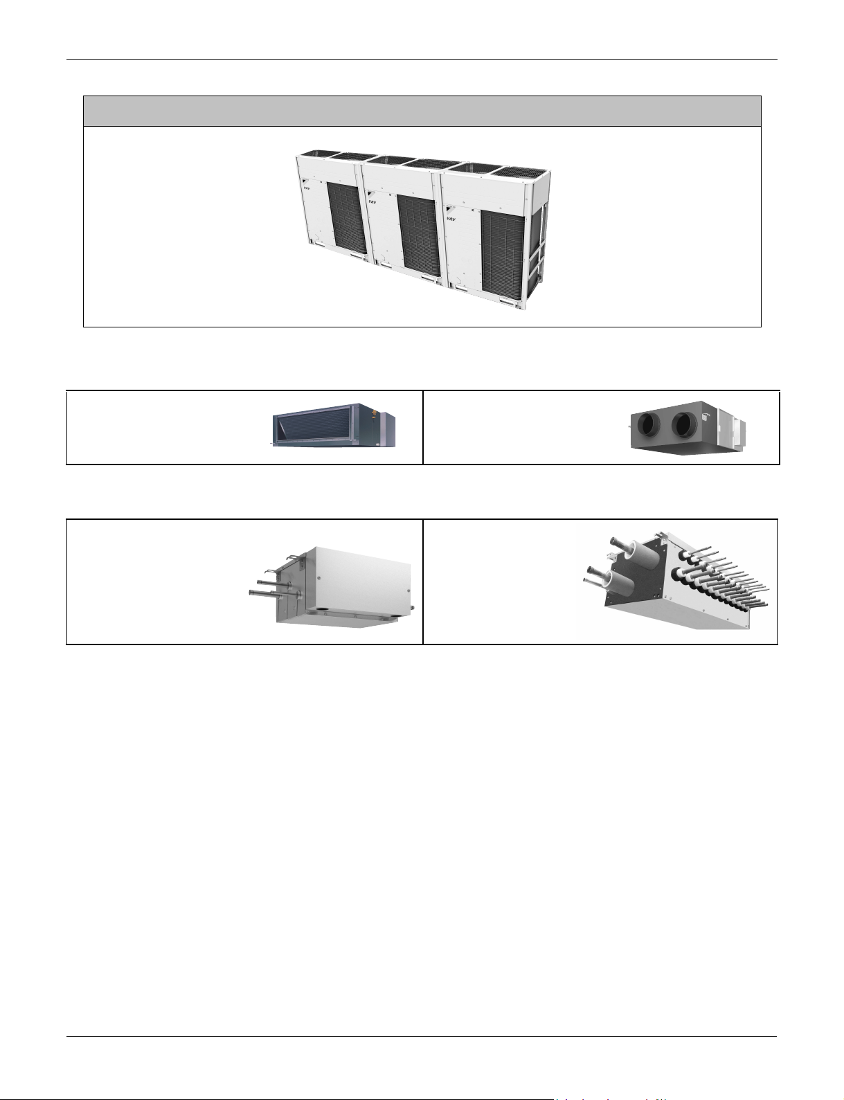
External Appearance SiUS371614E
Triple Outdoor Unit
REYQ360/384/408/432/456TAYDU
REYQ360/384/408/432/456TATJU
2.4 Air Treatment Equipment
Outdoor air processing unit
FXMQ-MF
2.5 Branch Selector Unit
Single branch selector unit
BSQ-T
Energy recovery ventilator
(VAM series)
VAM-G
Multi branch selector unit
BS-Q54T
7 General Information
SiUS371614E Combination of Outdoor Units
3. Combination of Outdoor Units
System capacity
Ton HP kW
6 7.5 21.1 1
8 10 28.1 1
10 12.5 35.2 1
12 15 42.2 1
14 17.5 49.2 1
16 20 56.3 2
18 22.5 63.3 2
20 25 70.3 2
22 27.5 77.4 2
24 30 84.4 2
26 32.5 91.4 2
28 35 98.5 2
30 37.5 105.5 3
32 40 112.5 3
34 42.5 119.6 3
36 45 126.6 3
38 47.5 133.6 3
Number of
units
72 96 120 144 168
O
OO
Module
Outdoor Unit Multi Connection
O
O
O
O
OO
OO
OO
OO
OO
OO
OOO
OO O
OOO
OOO
OO O
Piping Kit 1
—
BHFP26P100U
BHFP26P151U
Note: 1 For multiple connection, the outdoor unit multi connection piping kit (separately sold) is required.
General Information 8
Capacity Range SiUS371614E
4. Capacity Range
4.1 Combination Ratio
Combination ratio =
Type
Single outdoor units
Double outdoor units 160% ∗1
Triple outdoor units 130% 100%
Total capacity index of the indoor units
Capacity index of the outdoor units
Min.
combination
ratio
50% 200% ∗1 130%
Types of connected indoor units
When using
only FXDQ,
FXMQ-PB,
FXAQ
When using
only FXTQ,
or at least one
FXFQ07 or
FXFQ09
Max. combination ratio
Other
indoor unit
models
200% ∗1
Type of connected air treatment
When FXMQ-MF
is only connected
equipments
FXMQ-MF
When FXMQ-MF
and indoor units
are connected
100% 100% ∗2
When DVS are
connected
120%
Notes: ∗1. If the operational capacity of indoor units is more than 130%, low airflow operation is enforced in all
the indoor units. Refer to the table below.
∗2. When outdoor-air processing units (FXMQ-MF) and standard indoor units are connected, the total
connection capacity of the outdoor-air processing units (FXMQ-MF) must not exceed 30% of the
capacity index of the outdoor units. And the connection ratio must not exceed 100%.
4.2 Outdoor Unit Combinations
Capacity Range 6 ton 8 ton 10 ton 12 ton 14 ton 16 ton 18 ton 20 ton 22 ton
REYQ
Max. Number of
Connectable Indoor Units
Total Capacity Index of
Indoor Units to be
Connected ∗1
Capacity Range 24 ton 26 ton 28 ton 30 ton 32 ton 34 ton 36 ton 38 ton
REYQ
Max. Number of
Connectable Indoor Units
Total Capacity Index of
Indoor Units to be
Connected ∗1
72TAYDU
72TATJU
12 16 20 25 29 33 37 41 45
36~93
(144)
288TAYDU
288TATJU
49 54 58 62 64 64 64 64
144~374
(461)
Note: ∗1. Values inside brackets are based on connection of indoor units rated at maximum capacity, 200% for single
outdoor units, 160% for double outdoor units, and 130% for triple outdoor units.
96TAYDU
96TATJU
48~124
(192)
312TAYDU
312TATJU
156~405
(499)
120TAYDU
120TATJU
60~156
(240)
336TAYDU
336TATJU
168~436
(538)
144TAYDU
144TATJU
72~187
(288)
360TAYDU
360TATJU
180~468
(468)
168TAYDU
168TATJU
84~218
(336)
384TAYDU
384TATJU
192~499
(499)
192TAYDU
192TATJU
96~249
(307)
408TAYDU
408TATJU
204~530
(530)
216TAYDU
216TATJU
108~280
(346)
432TAYDU
432TATJU
216~561
(561)
240TAYDU
240TATJU
120~312
(384)
456TAYDU
456TATJU
228~592
(592)
264TAYDU
264TATJU
132~343
(422)
9 General Information
SiUS371614E Capacity Range
4.3 Limitation of Capacity Index for Heat Recovery
Single Branch Selector unit
Model BSQ36TVJ BSQ60TVJ BSQ96TVJ
Maximum number of connectable indoor units 4 8 8
Total capacity index of connectable indoor units unit ≤ 36 36 < unit ≤ 60 60 < unit ≤ 96
Multi Branch Selector unit
Model BS4Q54TVJ BS6Q54TVJ BS8Q54TVJ BS10Q54TVJ BS14Q54TVJ
Maximum number of connectable indoor units 20 30 40 41 41
Maximum number
branch
Number of branches 4 6 8 10 12
Maximum capacity index of connectable indoor
units
Maximum capacity index of connectable indoor
units per branch (*1)
Note: ∗1. When the total capacity of indoor units to be connected downstream is larger than 54 (Max. 96), use a junction
of connectable indoor units per
55555
144 or less 216 or less 290 or less 290 or less 290 or less
54 or less 54 or less 54 or less 54 or less 54 or less
pipe kit (KHRP26A250T, optional parts) to join 2 connections downstream from the Branch Selector unit.
Heat Recovery
High and low pressure
gas piping
Suction gas piping
Liquid piping
Outdoor unit
Indoor unit
(Heating)
Branch
Selector
unit
Indoor unit
(Cooling)
Branch
Selector
unit
Indoor unit∗
(Cooling only)
Heat Recovery operation!
∗ For indoor units used for cooling only (do not connect to Branch Selector unit when using for Heat Recovery),
total capacity index must be 50% or less than the capacity index of the outdoor units.
General Information 10

SiUS371614E
Part 2
Refrigerant Circuit
1. Refrigerant Circuit .....................................................................................12
1.1 Outdoor Unit ............................................................................................... 12
1.2 Indoor Unit.................................................................................................. 16
1.3 Outdoor-Air Processing Unit....................................................................... 18
1.4 Branch Selector Unit .................................................................................. 19
2. Functional Parts Layout ............................................................................25
2.1 REYQ72TAYDU ......................................................................................... 25
2.2 REYQ96/120TAYDU .................................................................................. 26
2.3 REYQ144/168TAYDU ................................................................................ 27
2.4 REYQ72TATJU .......................................................................................... 28
2.5 REYQ96/120TATJU ................................................................................... 29
2.6 REYQ144/168TATJU ................................................................................. 30
3. Refrigerant Flow for Each Operation Mode...............................................31
3.1 REYQ72TAYDU, REYQ72TATJU.............................................................. 31
3.2 REYQ96-168TAYDU, REYQ96-168TATJU ............................................... 37
11 Refrigerant Circuit
SiUS371614E Refrigerant Circuit
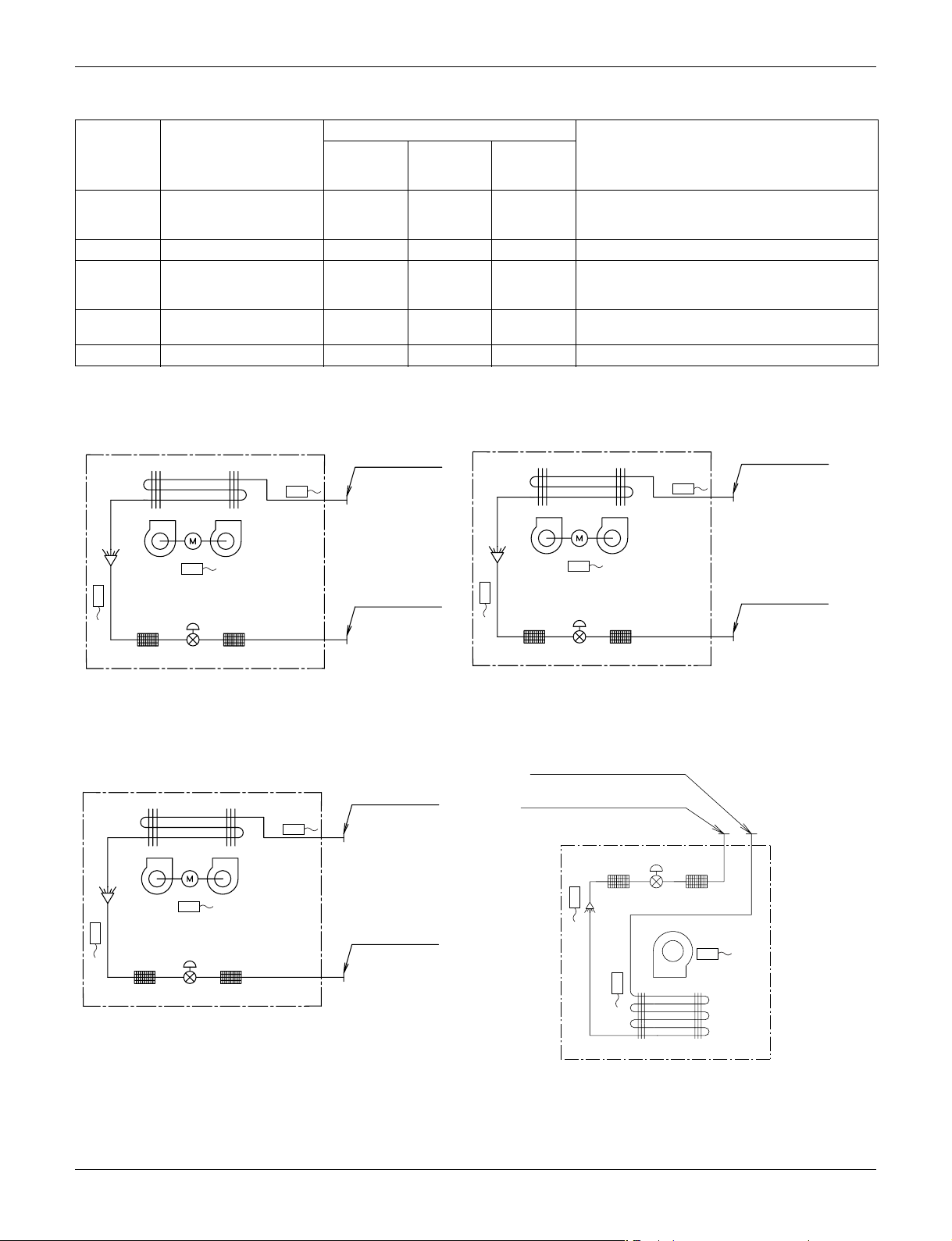
1. Refrigerant Circuit
1.1 Outdoor Unit
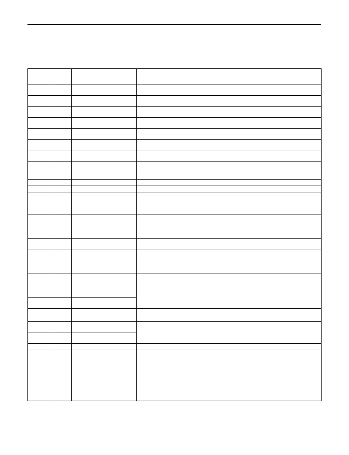
1.1.1 REYQ72TAYDU, REYQ72TATJU
No. in
piping
diagram
(10) Y3S Solenoid valve (Liquid shutoff) Used to return oil from the accumulator to the compressor.
(11) Y4S Four way valve (HP/LP gas) Used to switch dual pressure gas pipe to high pressure or low pressure.
(12) Y5S
(13) Y6S
(14) S1NPH High pressure sensor Used to detect the high pressure.
(15) S1NPL Low pressure sensor Used to detect the low pressure.
(16) S1PH
(17) —
(18) — Subcooling heat exchanger Apply subcooling to liquid refrigerant.
(19) — Capillary tube
(20) R1T Thermistor (Outdoor air) Used to detect outdoor air temperature, correct discharge pipe temperature and others.
(21) R2T Thermistor (M1C discharge) Used to detect discharge pipe temperature.
(22) R3T Thermistor (Receiver inlet) Used to detect liquid pipe temperature of receiver inlet.
(23) R4T
(24) R5T
(25) R6T Thermistor (Subcooling gas) Used to detect outdoor air temperature, correct discharge pipe temperature and others.
(26) R7T Thermistor (Subcooling liquid) This detects temperature of liquid pipe for subcooling heat exchanger.
(27) R8T
(28) R9T
(29) R10T Thermistor (Suction) Used to detect suction pipe temperature.
(30) R11T Thermistor (Deicer)
(31) R12T
(32) R13T
(33) R14T Thermistor (M1C body)
(34) R15T Thermistor (Leak detection) The thermistor detects refrigerant leakage.
Electric
symbol
(1) M1C Inverter compressor
(2) M1F Inverter fan
(3) Y1E
(4) Y2E
(5) Y3E
(6) Y4E
(7) Y5E
(8) Y6E
(9) Y1S Solenoid valve (OS oil return) Used to return oil from the oil separator to the compressor.
Electronic expansion valve
(Heat exchanger upper)
Electronic expansion valve
(Subcooling heat exchanger)
Electronic expansion valve
(Heat exchanger lower)
Electronic expansion valve
(Receiver gas purge)
Electronic expansion valve
(Refrigerant cooling)
Electronic expansion valve
(Leak detection)
Four way valve
(Heat exchanger lower)
Four way valve
(Heat exchanger upper)
High pressure switch
(For M1C)
Pressure regulating valve
(Liquid pipe)
Thermistor (Heat exchanger
liquid upper)
Thermistor (Heat exchanger
liquid lower)
Thermistor (Heat exchanger
gas upper)
Thermistor (Heat exchanger
gas lower)
Thermistor (Compressor
suction)
Thermistor
(Receiver gas purge)
Name Major function
Inverter compressor is operated on frequencies between 52 Hz to 210 Hz by using the
inverter. Compressor operation steps: Refer to page 66~
Because the system is an air heat exchange type, the fan is operated at 9-step rotation
speed by using the inverter.
While in heating, PI control is applied to keep the outlet superheated degree of air heat
exchanger constant.
PI control is applied to keep the outlet superheated degree of subcooling heat exchanger
constant.
While in heating, PI control is applied to keep the outlet superheated degree of air heat
exchanger constant.
Used to collect the refrigerant to receiver.
Used to control the refrigerant amount to cool the diode bridge and power module of the
inverter PCB.
Used to detect refrigerant leakage.
Used to switch outdoor heat exchanger to evaporator or condenser.
This functions when pressure increases to stop operation and avoid high pressure
increase in the fault operation.
This is used when pressure increases, to prevent any damage on components caused by
pressure increase in transport or storage.
Used to return the refrigerating oil separated through the oil separator to the M1C
compressor.
This detects temperature of liquid pipe for air heat exchanger.
This detects temperature of gas pipe for air heat exchanger.
Used to detect liquid pipe temperature of air heat exchanger. Used to make judgements
on defrost operation.
Used to detect suction pipe temperature of compressor.
Used to detect gas pipe temperature of receiver gas purge piping.
Detects compressor surface temperature, this switch is activated at surface temperature
of 120°C (248°F) or more to stop the compressor.
U
Refrigerant Circuit 12
Refrigerant Circuit SiUS371614E
REYQ72TAYDU, REYQ72TATJU
(22)
Check valveCheck valve
)
flare connection
)
7.9mm
(
valve
Electronic
expansion
Four way valve
(12)
(20)
Heat sink
Filter
Check valve
S1NPH
sensor
High pressure
Double tube
heat exchanger
(14)
Oil separator
S1PH
switch
(16)
High pressure
(32)
Filter
(21)
(9)
valve
Solenoid
port
Charge
tube
Capillary
Capillary
SV
(1)
M1C
Compressor
(33)
Filter
tube
(31)
(19)
plug
Fusible
Accumulator
C: 3D091128A
(7)
tube
Capillary
Check
valve
Electronic
expansion
(34)
valve
valve
(8)
expansion
(10)
SV
valve
valve
(6)
Filter
Capillary
Check
Liquid
tube
(18)
(2)
Pressure
regulating
Fusible
Receiver
Filter
Check valve
Fan
Electronic
Check valve
Solenoid
Electronic expansion
(5)
(24)
(30)
(27)
(13)
valve
Electronic expansion
Filter
Filter
(28)
Four way valve
(3)
valve
(23)
Filter
M
(17)
valve
plug
Filter
Check valve
With service port φ5/16in.
(
(26)
Filter
Stop valve
Liquid
pipe
valve
Electronic
expansion
(4)
Double tube
heat exchanger
(25)
Four way valve
(11)
pipe
High/low pressure gas
(15)
sensor
Low pressure
(29)
S1NPL
pipe
Suction gas
13 Refrigerant Circuit
SiUS371614E Refrigerant Circuit
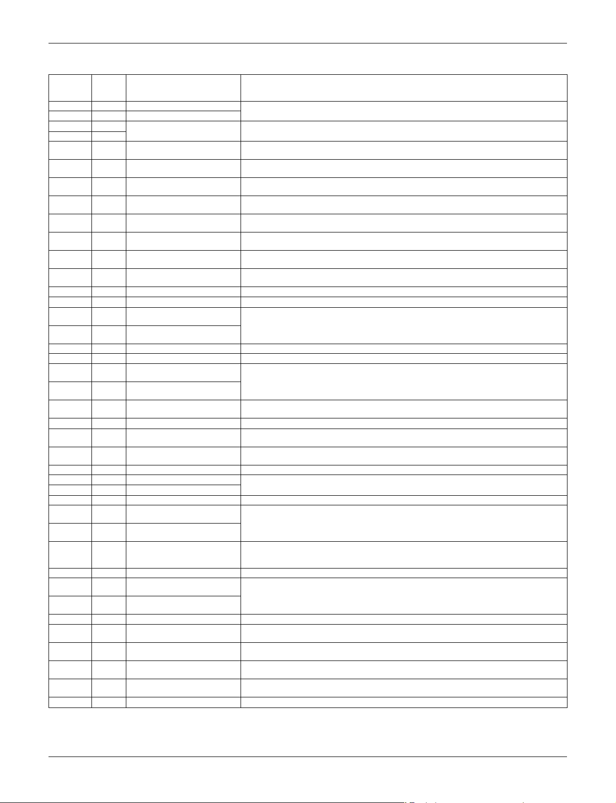
1.1.2 REYQ96-168TAYDU, REYQ96-168TATJU
No. in
piping
diagram
(10) Y6E
(11) Y1S
(12) Y2S
(13) Y3S Solenoid valve (Liquid shutoff) Used to return oil from the accumulator to the compressor.
(14) Y4S Four way valve (HP/LP gas) Used to switch dual pressure gas pipe to high pressure or low pressure.
(15) Y5S
(16) Y6S
(17) S1NPH High pressure sensor Used to detect the high pressure.
(18) S1NPL Low pressure sensor Used to detect the low pressure.
(19) S1PH
(20) S2PH
(21) —
(22) — Subcooling heat exchanger Apply subcooling to liquid refrigerant.
(23) — Capillary tube
(24) — Capillary tube
(25) R1T Thermistor (Outdoor air) Used to detect outdoor air temperature, correct discharge pipe temperature and others.
(26) R21T Thermistor (M1C discharge)
(27) R22T Thermistor (M2C discharge)
(28) R3T Thermistor (Receiver inlet) Used to detect liquid pipe temperature of receiver inlet.
(29) R4T
(30) R5T
(31) R6T Thermistor (Subcooling gas)
(32) R7T Thermistor (Subcooling liquid) This detects temperature of liquid pipe for subcooling heat exchanger.
(33) R8T
(34) R9T
(35) R10T Thermistor (Suction) Used to detect suction pipe temperature.
(36) R11T Thermistor (Deicer)
(37) R12T
(38) R13T
(39) R14T Thermistor (M2C body)
(40) R15T Thermistor (Leak detection) The thermistor detects refrigerant leakage.
Electric
symbol
(1) M1C Inverter compressor
(2) M2C Inverter compressor
(3) M1F
(4) M2F
(5) Y1E
(6) Y2E
(7) Y3E
(8) Y4E
(9) Y5E
Inverter fan
Electronic expansion valve
(Heat exchanger upper)
Electronic expansion valve
(Subcooling heat exchanger)
Electronic expansion valve
(Heat exchanger lower)
Electronic expansion valve
(Receiver gas purge)
Electronic expansion valve
(Refrigerant cooling)
Electronic expansion valve
(Leak detection)
Solenoid valve
(OS oil return 1)
Solenoid valve
(OS oil return 2)
Four way valve
(Heat exchanger lower)
Four way valve
(Heat exchanger upper)
High pressure switch
(For M1C)
High pressure switch
(For M2C)
Pressure regulating valve
(Liquid pipe)
Thermistor (Heat exchanger
liquid upper)
Thermistor (Heat exchanger
liquid lower)
Thermistor (Heat exchanger
gas upper)
Thermistor (Heat exchanger
gas lower)
Thermistor (Compressor
suction)
Thermistor
(Receiver gas purge)
Name Major function
Inverter compressor is operated on frequencies between 52 Hz to 210 Hz by using the
inverter. Compressor operation steps: Refer to page 66~
Because the system is an air heat exchange type, the fan is operated at 9-step rotation
speed by using the inverter.
While in heating, PI control is applied to keep the outlet superheated degree of air heat
exchanger constant.
PI control is applied to keep the outlet superheated degree of subcooling heat exchanger
constant.
While in heating, PI control is applied to keep the outlet superheated degree of air heat
exchanger constant.
Used to collect the refrigerant to receiver.
Used to control the refrigerant amount to cool the diode bridge and power module of the
inverter PCB.
Used to detect refrigerant leakage.
Used to return oil from the oil separator to the compressor (M1C).
Used to return oil from the oil separator to the compressor (M2C).
Used to switch outdoor heat exchanger to evaporator or condenser.
This functions when pressure increases to stop operation and avoid high pressure
increase in the fault operation.
This is used when pressure increases, to prevent any damage on components caused by
pressure increase in transport or storage.
Used to return the refrigerating oil separated through the oil separator to the M1C
compressor.
Used to return the refrigerating oil separated through the oil separator to the M2C
compressor.
Used to detect discharge pipe temperature.
This detects temperature of liquid pipe for air heat exchanger.
Used to detect gas pipe temperature on the evaporating side of subcooling heat
exchanger. Used to exercise the constant control of superheated degree at the outlet of
subcooling heat exchanger.
This detects temperature of gas pipe for air heat exchanger.
Used to detect liquid pipe temperature of air heat exchanger. Used to make judgements
on defrost operation.
Used to detect suction pipe temperature of compressor.
Used to detect gas pipe temperature of receiver gas purge piping.
Detects compressor surface temperature, this switch is activated at surface temperature
of 120°C (248°F) or more to stop the compressor. (144/168 class models only)
Refrigerant Circuit 14
Refrigerant Circuit SiUS371614E
REYQ96-168TAYDU, REYQ96-168TATJU
(25)
(9)
valve
Filter
(19)
Filter
S1NPH
sensor
High pressure
(20)
Oil Separator
Filter
(26)
switch
S1PH
High pressure
Oil Separator
Filter
(27)
S2PH
switch
High pressure
SV
valve
Solenoid
(1) (11)
SV
valve
Solenoid
(2) (12)
Check
Heat sink
Check
valve
valve
(17)
tube
valve
valve
Pressure
Receiver
valve
Electronic
expansion
(5)
(29)
MM
(4) (3)
Fan Fan
(21)
valve
regulating
plug
Fusible
Filter
(7)
(30)
Filter
(36)
(33)
Capillary
(28)
Electronic
Check valve
Check valve
Check
(40)
expansion valve
(10)
Check
(13)
SV
Solenoid valve
Electronic expansion
valve
Electronic expansion
Filter
(34)
(23)
Capillary
tube
M1CCapillary
Compressor
(24)
tube
M2C
Compressor
(39)
(37)
C: 3D091127A
)
flare connection
)
7.9mm
(
Check valve
With service port φ5/16in.
(
(32)
Filter
Stop valve
Check valve
Electronic expansion valve
valve
Electronic
expansion
Four way valve
Filter
Filter
tube
Capillary
Check valve
(8)
(22)
(6)
Double tube
heat exchanger
Filter
(16)
(31)
(15)
Four way valve
Four way valve
(38)
Double tube
heat exchanger
Four way valve
(14)
port
Charge
tube
Capillary
S1NPL
sensor
Lows pressure
(18)
Filter
(35)
Fusible
Accumulator
plug
pipe
Liquid
pipe
High/low pressure gas
pipe
Suction gas
15 Refrigerant Circuit
SiUS371614E Refrigerant Circuit
1.2 Indoor Unit
Symbol
No. in piping
diagram
(1)
Electronic expansion
valve
Name
(2) Suction air thermistor R1T R1T R1T (∗1) Used for thermostat control.
(3) Liquid pipe thermistor R2T R2T R2T
(4) Gas pipe thermistor R3T R3T R3T
(5) Discharge air thermistor — R4T — Used for discharge air temperature control.
∗1. R1T is for remote controller thermistor or optional remote sensor.
FXFQ-T, FXFQ-P, FXHQ-M FXZQ-M
(4)
Except
FXMQ-PB,
FXMQ-PB FXTQ-TA
FXTQ-TA
Y1E Y1E Y1E
Gas piping
connection port
Function
Used for gas superheated degree control while
in cooling or subcooled degree control while in
heating.
Used for gas superheated degree control while
in cooling or subcooled degree control while in
heating.
Used for gas superheated degree control while
in cooling.
Gas piping
connection port
(4)
Indoor heat exchanger
Fan
(3)
Filter Filter
(2)
(1)
Liquid piping
connection port
C: 4D024460M
FXUQ-P, FXEQ-P, FXMQ-M, FXAQ-P, FXLQ-M,
FXNQ-M
Gas piping
connection port
(4)
Indoor heat exchanger
Fan
(3)
Filter Filter
(2)
(1)
Liquid piping
connection port
C: 4D034245P
Indoor heat exchanger
(3)
Filter Filter
FXDQ-M
Gas piping connection port
Liquid piping connection port
Fan
(2)
(1)
(3)
Filter
(4)
(1)
Filter
(2)
Fan
Liquid piping
connection port
C: 4D040157B
Indoor heat exchanger
C: 4D043864N
Refrigerant Circuit 16
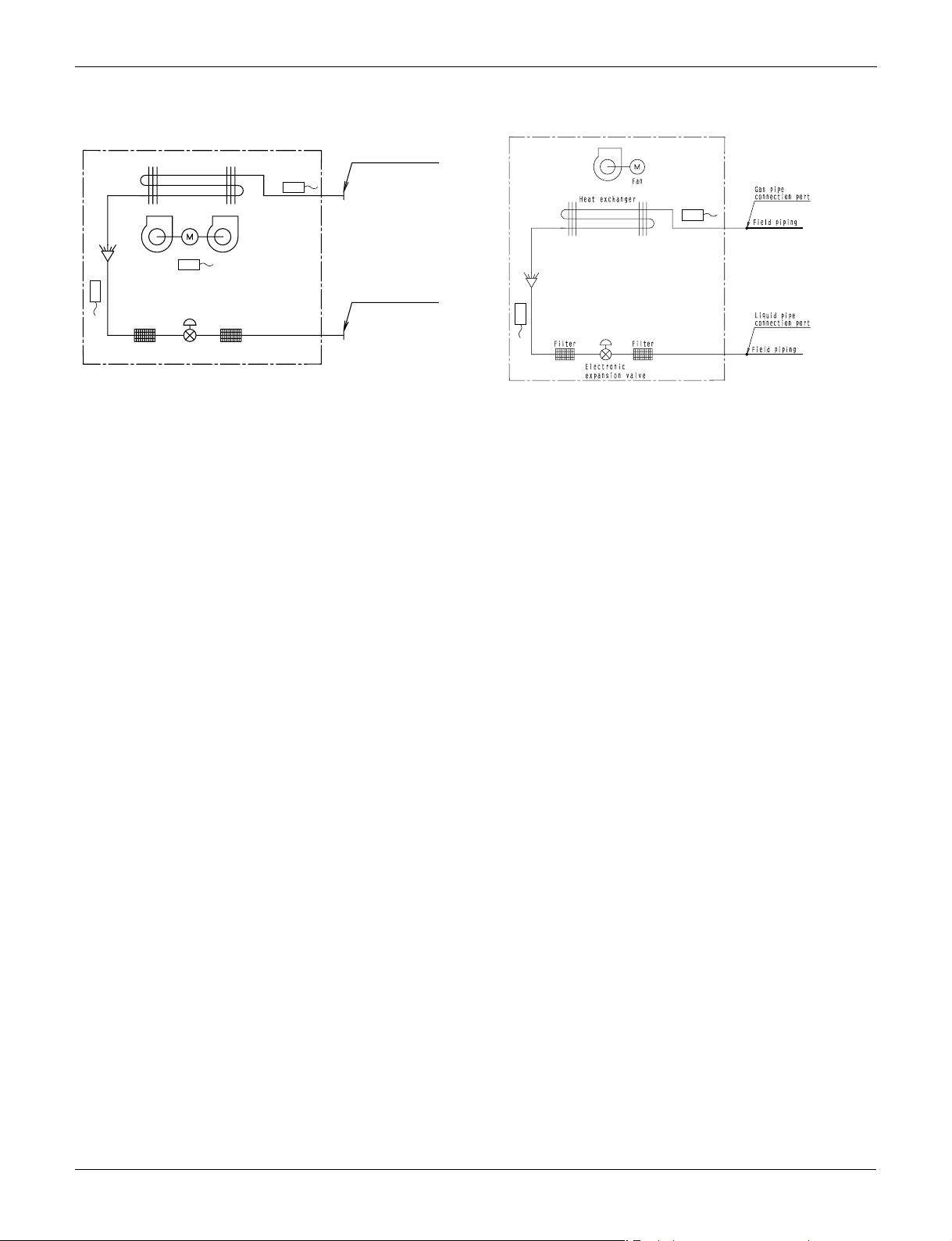
Refrigerant Circuit SiUS371614E
FXMQ-PB FXTQ-TA
Gas piping
connection port
(4)
Indoor heat exchanger
(3)
Filter Filter
Fan
(2)
(1)
Liquid piping
connection port
C: 4D034245P
(4)
(3)
(1)
C: 4D068194
17 Refrigerant Circuit
 Loading...