

Daikin RPS, RFS, RPE, RDT, RDE User Manual
...
Installation and Maintenance Manual IM-790
Group: Applied Systems
Part Number: IM790
Date: June 2004
Ultraviolet Lights on
Daikin Applied Rooftop Systems and Rooftop Air Handlers
Models RPS/RDT/RFS/RPE/RDE/RDS/RAH
© 2004 Daikin Applied
IM-790 Page 1
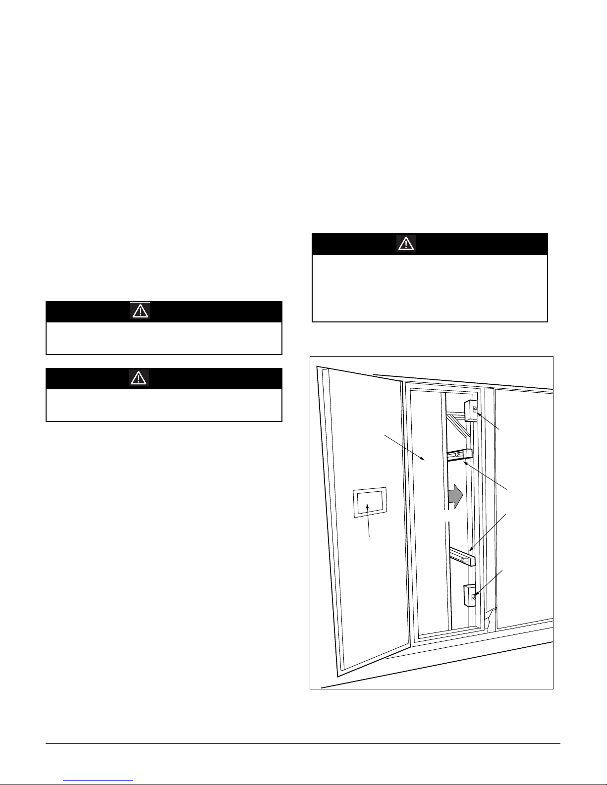
Table of Contents
Introduction........................................................................................................................................................................................... 2
Description ...................................................................................................................................................................
Operation......................................................................................................................................................................
Maintenance........................................................................................................................
.................................................................. 4
Bulb Replacement........................................................................................................................................................
Typical Parts List ................................................................................................................
.................................................................. 4
Introduction
This manual provides general information about the Ultraviolet Lig
models RPS/RDT/RFS/RPE/RDE/RDS and RAH. In addition to an overall description of the unit, it includes removal
and installation procedures, maintenance instructions and
parts identification.
Hazard Identification Information
ht option for Daikin RoofPak® applied rooftop
WARNING
Warnings indicate hazardous situations which, if not
avoided, can result in severe personal injury or property
damage.
WARNIN G
UVC exposure is harmful to the skin and eyes.
Looking at an illuminated bulb can cause
permanent blindness. Skin exposure can cause
Cancer.
Always disconnect power to unit before servicing. Do
not operate if disconnect switch has been disabled.
Figure 1. Typical Ultraviolet Light Installation
................. 2
................. 3
................. 4
CCAUTION
Cautions indicate hazardous situations which, if not
avoided, can result in personal injury or equipment
damage.
Description
Ultraviolet C light bathes the moist surfaces on the coil and
drain pan, killing most microorganisms that can grow there.
Ultraviolet lights are typically installed on the leaving side of
the cool
rail and is removable for convenient bulb replacement.
UV Light Power Disconnect switches (
tory installed on every door that allows a direct line of sight to
the
prevent UV exposure when cabinet doors are opened and must
not be disabled.
A viewing window near the UV lights allows viewing to determine if the lights are energized. The v
cially designed glass that blocks harmful UV light.
ing coils in the unit. Each light module is mounted on a
two per door) are fac-
UV lamps when opened. These switches are designed to
iewing windows use spe-
Cooling
Coil
View
Window
AIRFLOW
Light Power
Disconnect
Switch
Ultraviolet
Light
Units
Light Power
Disconnect
Switch
Page 2 IM-790
 Loading...