

Daikin FT20FV1M, R20FV1M, FT25FV1M, R25FV1M, FT35FV1M Installation Manual
...
14
WALL MOUNTED
SPLIT TYPE AIR CONDITIONER
WALL MOUNTED
INSTALLATION MANUAL
Part No.: R08019028786
IM-WMG-0906-DAIKIN

1
English
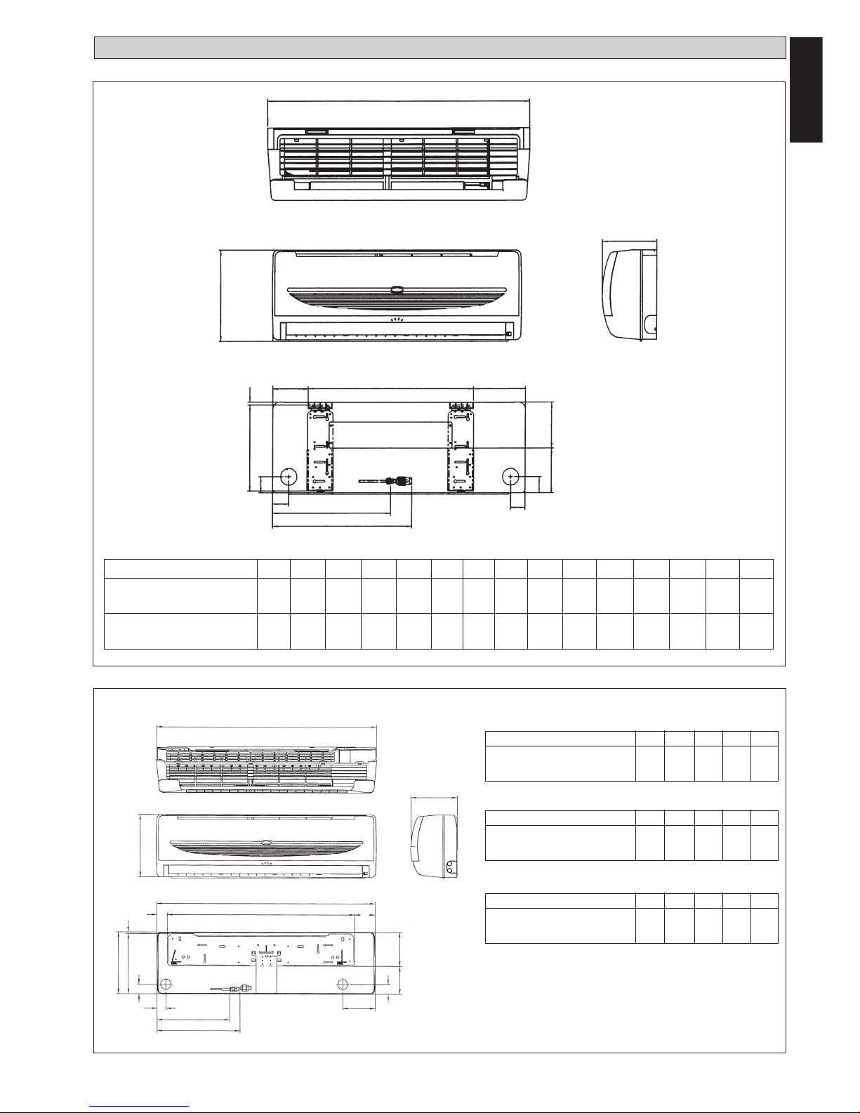
OUTLINE AND DIMENSIONS
All dimensions are in mm/ (in)
FRONT VIEW
TOP VIEW
A
C
DG
F
SIDE VIEW
INSTALLATION
PLATE
O
N
I
M
B
E
H
I
J
K
L
Dimension A B C D E F G H I J K L M N O
FT20FV1M/FT25FV1M 799 260 198 379 246 185 124 8 56 50 319 379 50 128 132
(31.5) (10.2) (7.8) (15.0) (9.7) (7.3) (4.9) (0.3) (2.2) (2.0) (12.6) (15.0) (2.0) (5.1) (5.2)
FT28FV1M/FT35FV1M 899 260 198 590 246 185 124 8 56 50 419 495 50 128 132
(35.4) (10.2) (7.8) (23.2) (9.7) (7.3) (4.9) (0.3) (2.2) (2.0) (16.5) (19.5) (2.0) (5.1) (5.2)
Dimension A B C D E
FT50FV1M / FT60FV1M9 1060 310 220 912 294
(41.7) (12.2) (8.6) (35.9) (11.6)
FRONT VIEW
TOP VIEW
INSTALLATION
PLATE
I
O
N
SIDE VIEW
C
A
D
CENTER LINE
F
B
G
H
B
M
I
K
L
J
A
Indoor Unit
All dimensions are in mm/ (in)
Dimension K L M N O
FT50FV1M / FT60FV1M9 354 403 160 138 160
(13.9) (15.9) (6.3) (5.4) (6.3)
Dimension F G H I J
FT50FV1M / FT60FV1M9 99 51 8 48 43
(3.9) (2.0) (0.3) (1.9) (1.7)
M

2
All dimensions are in mm/ (in)
30
(1.2)
19
(0.7)
65
(2.6)
80
(3.1)
L
K
L
NC
M
N
D
A
O
B
E
F
C
GH
I
J
Dimension A B C
R20FV1M/R25FV1M 600 475 245
(23.6) (18.7) (9.6)
R35FV1M 700 521 250
(27.5) (20.5) (9.8)
Dimension G H I
R20FV1M/R25FV1M 93 81 83
(3.6) (3.1) (3.2)
R35FV1M 95 93 86
(3.7) (3.6) (3.3)
Dimension J K L
R20FV1M/R25FV1M 55 398 101
(2.2) (15.6) (3.9)
R35FV1M 68 441 130
(2.6) (17.3) (5.1)
Dimension M N O
R20FV1M/R25FV1M 97 17 22
(3.8) (0.6) (0.8)
R35FV1M 111 15 18
(4.3) (0.5) (0.7)
Dimension D E F
R20FV1M/R25FV1M 418 177 35
(16.4) (6.9) (1.3)
R35FV1M 485 175 36
(19.1) (6.8) (1.4)
3
(0.1)
Outdoor Unit
Dimension A B C D E F G H I J K L M N O
R50FV1M 855 628 328 513 182 44 93 149 101 113 603 126 164 17 49
(33.7) (24.7) (12.9) (20.0) (7.1) (1.7) (3.7) (5.9) (4.0) (4.4) (23.7) (5.0) (6.4) (0.7) (1.9)
R60FV1M9 855 730 328 513 182 44 93 149 101 113 603 126 164 17 47
(33.7) (28.7) (12.9) (20.2) (7.2) (1.7) (3.7) (5.9) (4.0) (4.4) (23.7) (5.0) (6.4) (0.7) (1.9)
KL
C
M
N
A
D
N
P
FE
C
GH
B
Q
R
O
L
ST
IJ
Dimension P Q R S T
R50FV1M 32 3 23 73 75
(1.3) (0.1) (0.9) (2.9) (3.0)
R60FV1M9 32 3 23 73 75
(1.3) (0.1) (0.9) (2.9) (3.0)
All dimensions are in mm/ (in)
FOR R71FV1M
ONLY
3
English
MODEL
Indoor Outdoor
FT20FV1M R20FV1M
FT25FV1M R25FV1M
FT35FV1M R35FV1M
FT50FV1M R50FY1M
FT60FV1M9 R60FV1M9
This manual provides the procedures of installation to ensure a safe and good standard of operation for the air conditioner unit.
Special adjustment may be necessary to suit local requirements.
Before using your air conditioner, please read this instruction manual carefully and keep it for future reference.
INSTALLATION MANUAL
SAFETY PRECAUTIONS
! CAUTION
Please take note of the following important points when installing.
• Do not install the unit where leakage of flammable gas may occur.
If gas leaks and accumulates around the unit. it may cause fire
ignition.
• Ensure that the drainage piping is connected properly.
If the drainage piping is not connected properly. it may cause
water leakage which will dampen the furniture.
• Do not overcharge the unit.
This unit is factory pre-charged. Overcharge will cause overcurrent or damage to the compressor.
• Ensure that the units panel is closed after service or installation.
Unsecured panels will cause the unit to operate noisily.
• Sharp edges and coil surfaces are potential locations which may
cause injury hazards. Avoid from being in contact with these
places.
• Before turning off the power supply. set the remote controller’s
ON/OFF switch to the “OFF” position to prevent the nuisance
tripping of the unit. If this is not done. the unit’s fans will start turning
automatically when power resumes. posing a hazard to service
personnel or the user.
• Do not operate any heating apparatus too close to the air
conditioner unit. This may cause the plastic panel to melt or deform
as a result of the excessive heat.
• Ensure the color of wires of the outdoor unit and the terminal
markings are same to the indoors respectively.
• IMPORTANT : DO NOT INSTALL OR USE THE AIR
CONDITIONER UNIT IN A LAUNDRY ROOM.
! WARNING
• Installation and maintenance should be performed by
qualified persons who are familiar with local code and
regulation. and experienced with this type of
appliance.
• All field wiring must be installed in accordance with
the national wiring regulation.
• Ensure that the rated voltage of the unit corresponds
to that of the name plate before commencing wiring
work according to the wiring diagram.
• The unit must be GROUNDED to prevent possible
hazard due to insulation failure.
• All electrical wiring must not touch the refrigerant
piping or any moving parts of the fan motors.
• Confirm that the unit has been switched OFF before
installing or servicing the unit.
• Disconnect from the main power supply before
servicing the air conditioner unit.
• DO NOT pull out the power cord when the power is
ON. This may cause serious electrical shocks which
may result in the fire hazards.
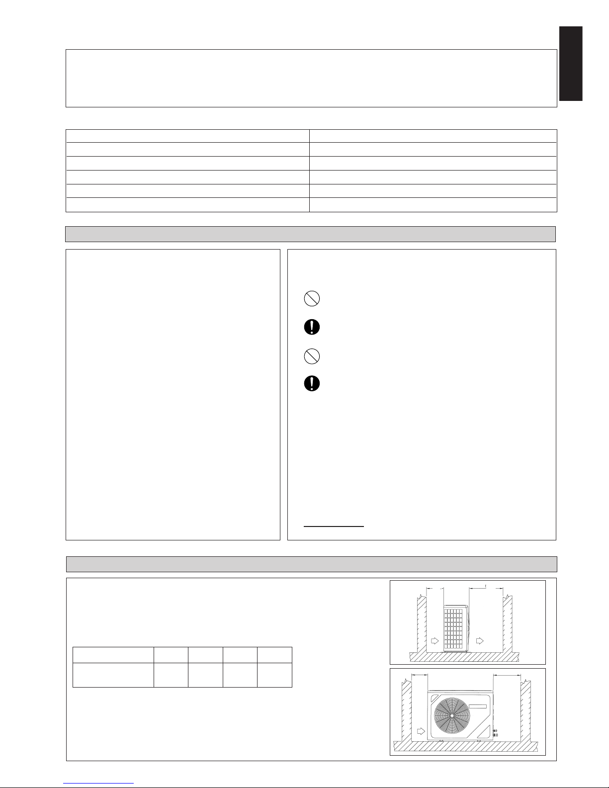
INSTALLATION OF THE OUTDOOR UNIT
The outdoor unit must be installed in such a way, so as to prevent short circuit of the hot
discharged air or obstruction to the smooth air flow. Please follow the installation clearances
shown in the figure. Select the coolest possible place where intake air temperature is not
greater than the outside air temperature (maximum 45°C).
Dimension A B C D
Minimum Distance, 300 1000 300 500
mm (in) (11.8) (39.4) (11.8) (19.7)
Installation Clearances
Note: If there is any obstacle higher than 2m, or if there is any obstruction at
the upper part of the unit, please allow more space than the figure indicated in
the above table.
Obstacle
Return Air
Discharge Air
Obstacle
AB
C
D
Obstacle
Return Air
Service
Access
Obstacle
 Loading...