

Daikin FXFQ20BVEB, FXFQ25BVEB, FXFQ32BVEB, FXFQ40BVEB, FXFQ50BVEB Installer reference guide
...Page 1

Installer and user
reference guide
VRV system air conditioner
FXFQ20BVEB
FXFQ25BVEB
FXFQ32BVEB
FXFQ40BVEB
FXFQ50BVEB
FXFQ63BVEB
FXFQ80BVEB
FXFQ100BVEB
FXFQ125BVEB
Installer and user reference guide
VRV system air conditioner
English
Page 2

Table of contents
Table of contents
1 General safety precautions 3
1.1 About the documentation .......................................................... 3
1.1.1 Meaning of warnings and symbols.............................. 3
1.2 For the user ............................................................................... 3
1.3 For the installer.......................................................................... 3
1.3.1 General ....................................................................... 3
1.3.2 Installation site ............................................................ 4
1.3.3 Refrigerant .................................................................. 5
1.3.4 Brine............................................................................ 6
1.3.5 Water .......................................................................... 6
1.3.6 Electrical ..................................................................... 6
2 About the documentation 7
2.1 About this document.................................................................. 7
For the installer 8
3 About the box 8
3.1 Overview: About the box ........................................................... 8
3.2 Indoor unit ................................................................................. 8
3.2.1 To unpack and handle the unit.................................... 8
3.2.2 To remove the accessories from the indoor unit......... 8
4 About the units and options 8
4.1 Overview: About the units and options...................................... 8
4.2 Identification .............................................................................. 8
4.2.1 Identification label: Indoor unit .................................... 9
4.3 System layout............................................................................ 9
4.4 Combining units and options ..................................................... 9
4.4.1 Possible options for the indoor unit............................. 9
5 Preparation 9
5.1 Overview: Preparation............................................................... 9
5.2 Preparing the installation site .................................................... 9
5.2.1 Installation site requirements of the indoor unit .......... 9
5.3 Preparing refrigerant piping....................................................... 10
5.3.1 Refrigerant piping requirements.................................. 10
5.3.2 Refrigerant piping insulation ....................................... 11
5.4 Preparing electrical wiring ......................................................... 11
5.4.1 About preparing electrical wiring................................. 11
6 Installation 11
6.1 Overview: Installation ................................................................ 11
6.2 Mounting the indoor unit............................................................ 11
6.2.1 Precautions when mounting the indoor unit................ 11
6.2.2 Guidelines when installing the indoor unit................... 11
6.2.3 Guidelines when installing the drain piping................. 12
6.3 Connecting the refrigerant piping .............................................. 14
6.3.1 About connecting the refrigerant piping ...................... 14
6.3.2 Precautions when connecting the refrigerant piping... 14
6.3.3 Guidelines when connecting the refrigerant piping..... 14
6.3.4 Pipe bending guidelines.............................................. 15
6.3.5 To flare the pipe end................................................... 15
6.3.6 To connect the refrigerant piping to the indoor unit .... 15
6.4 Connecting the electrical wiring................................................. 15
6.4.1 About connecting the electrical wiring......................... 15
6.4.2 Precautions when connecting the electrical wiring ..... 16
6.4.3 Guidelines when connecting the electrical wiring ....... 16
6.4.4 Specifications of standard wiring components............ 16
6.4.5 To connect the electrical wiring on the indoor unit...... 16
7 Configuration 17
7.1 Field settings ............................................................................. 17
8 Commissioning 18
8.1 Overview: Commissioning......................................................... 18
8.2 Precautions when commissioning .............................................. 19
8.3 Checklist before commissioning................................................. 19
8.4 To perform a test run.................................................................. 19
8.5 Error codes when performing a test run ..................................... 20
9 Hand-over to the user 20
10 Disposal 20
11 Technical data 20
11.1 Piping diagram: Indoor unit ........................................................ 21
11.2 Wiring diagram ........................................................................... 21
11.2.1 Unified wiring diagram legend...................................... 21
For the user 22
12 About the system 22
12.1 System layout ............................................................................. 22
12.2 Information requirements for fan coil units ................................. 22
13 User interface 22
14 Before operation 22
15 Operation 23
15.1 Operating the system ................................................................. 23
15.1.1 About operating the system ......................................... 23
15.1.2 About cooling, heating, fan only, and automatic
operation ...................................................................... 23
15.1.3 About the heating operation ......................................... 23
15.1.4 To operate the system ................................................. 23
15.2 Using the dry program ................................................................ 23
15.2.1 About the dry program ................................................. 23
15.2.2 To use the dry program................................................ 23
15.3 Adjusting the air flow direction.................................................... 24
15.3.1 About the air flow flap .................................................. 24
15.4 Active circulation airflow ............................................................. 24
15.4.1 To start the active circulation airflow ............................ 24
16 Energy saving and optimum operation 24
17 Maintenance and service 25
17.1 Precautions for maintenance and service .................................. 25
17.2 Cleaning the air filter, suction grille, air outlet and outside
panels......................................................................................... 25
17.2.1 To clean the air filter .................................................... 25
17.2.2 To clean the suction grille ............................................ 26
17.2.3 To clean the air outlet and outside panels ................... 26
17.3 Maintenance after a long stop period ......................................... 26
17.4 Maintenance before a long stop period ...................................... 26
17.5 About the refrigerant................................................................... 26
17.6 After-sales service and warranty ................................................ 27
17.6.1 Warranty period ........................................................... 27
17.6.2 Recommended maintenance and inspection ............... 27
17.6.3 Recommended maintenance and inspection cycles .... 27
17.6.4 Shortened maintenance and replacement cycles ........ 27
18 Troubleshooting 27
18.1 Symptoms that are NOT system malfunctions ........................... 28
18.1.1 Symptom: The system does not operate ..................... 28
18.1.2 Symptom: The fan speed does not correspond to the
setting .......................................................................... 28
18.1.3 Symptom: The fan direction does not correspond to
the setting .................................................................... 28
18.1.4 Symptom: White mist comes out of a unit (Indoor
unit) .............................................................................. 28
18.1.5 Symptom: White mist comes out of a unit (Indoor
unit, outdoor unit) ......................................................... 28
18.1.6 Symptom: The user interface display reads "U4" or
"U5" and stops, but then restarts after a few minutes.. 28
18.1.7 Symptom: Noise of air conditioners (Indoor unit) ......... 28
Installer and user reference guide
2
FXFQ20~125BVEB
VRV system air conditioner
4P561452-1 – 2018.12
Page 3
1 General safety precautions
18.1.8 Symptom: Noise of air conditioners (Indoor unit,
outdoor unit)................................................................ 29
18.1.9 Symptom: Noise of air conditioners (Outdoor unit) ..... 29
18.1.10 Symptom: Dust comes out of the unit ......................... 29
18.1.11 Symptom: The units can give off odours..................... 29
18.1.12 Symptom: The outdoor unit fan does not spin ............ 29
18.1.13 Symptom: The display shows "88".............................. 29
18.1.14 Symptom: The compressor in the outdoor unit does
not stop after a short heating operation ...................... 29
19 Relocation 29
20 Disposal 29
21 Glossary 29
1 General safety precautions
1.1 About the documentation
▪ The original documentation is written in English. All other
languages are translations.
▪ The precautions described in this document cover very important
topics, follow them carefully.
▪ The installation of the system, and all activities described in the
installation manual and the installer reference guide MUST be
performed by an authorised installer.
1.1.1 Meaning of warnings and symbols
Symbol Explanation
For more information, see the installer and user
reference guide.
1.2 For the user
▪ If you are NOT sure how to operate the unit, contact your installer.
▪ This appliance can be used by children aged from 8 years and
above and persons with reduced physical, sensory or mental
capabilities or lack of experience and knowledge if they have been
given supervision or instruction concerning use of the appliance in
a safe way and understand the hazards involved. Children shall
NOT play with the appliance. Cleaning and user maintenance
shall NOT be made by children without supervision.
WARNING
To prevent electric shocks or fire:
▪ Do NOT rinse the unit.
▪ Do NOT operate the unit with wet hands.
▪ Do NOT place any objects containing water on the unit.
NOTICE
▪ Do NOT place any objects or equipment on top of the
unit.
▪ Do NOT sit, climb or stand on the unit.
▪ Units are marked with the following symbol:
DANGER
Indicates a situation that results in death or serious injury.
DANGER: RISK OF ELECTROCUTION
Indicates a situation that could result in electrocution.
DANGER: RISK OF BURNING
Indicates a situation that could result in burning because of
extreme hot or cold temperatures.
DANGER: RISK OF EXPLOSION
Indicates a situation that could result in explosion.
WARNING
Indicates a situation that could result in death or serious
injury.
WARNING: FLAMMABLE MATERIAL
CAUTION
Indicates a situation that could result in minor or moderate
injury.
NOTICE
Indicates a situation that could result in equipment or
property damage.
This means that electrical and electronic products may NOT be
mixed with unsorted household waste. Do NOT try to dismantle
the system yourself: the dismantling of the system, treatment of
the refrigerant, of oil and of other parts must be done by an
authorized installer and must comply with applicable legislation.
Units must be treated at a specialized treatment facility for reuse,
recycling and recovery. By ensuring this product is disposed of
correctly, you will help to prevent potential negative consequences
for the environment and human health. For more information,
contact your installer or local authority.
▪ Batteries are marked with the following symbol:
This means that the batteries may NOT be mixed with unsorted
household waste. If a chemical symbol is printed beneath the
symbol, this chemical symbol means that the battery contains a
heavy metal above a certain concentration.
Possible chemical symbols are: Pb: lead (>0.004%).
Waste batteries must be treated at a specialized treatment facility
for reuse. By ensuring waste batteries are disposed of correctly,
you will help to prevent potential negative consequences for the
environment and human health.
1.3 For the installer
INFORMATION
Indicates useful tips or additional information.
Symbol Explanation
Before installation, read the installation and
operation manual, and the wiring instruction sheet.
Before performing maintenance and service tasks,
read the service manual.
FXFQ20~125BVEB
VRV system air conditioner
4P561452-1 – 2018.12
1.3.1 General
If you are NOT sure how to install or operate the unit, contact your
dealer.
Installer and user reference guide
3
Page 4
1 General safety precautions
NOTICE
Improper installation or attachment of equipment or
accessories could result in electric shock, short-circuit,
leaks, fire or other damage to the equipment. Only use
accessories, optional equipment and spare parts made or
approved by Daikin.
WARNING
Make sure installation, testing and applied materials
comply with applicable legislation (on top of the
instructions described in the Daikin documentation).
CAUTION
Wear adequate personal protective equipment (protective
gloves, safety glasses,…) when installing, maintaining or
servicing the system.
WARNING
Tear apart and throw away plastic packaging bags so that
nobody, especially children, can play with them. Possible
risk: suffocation.
DANGER: RISK OF BURNING
▪ Do NOT touch the refrigerant piping, water piping or
internal parts during and immediately after operation. It
could be too hot or too cold. Give it time to return to
normal temperature. If you must touch it, wear
protective gloves.
▪ Do NOT touch any accidental leaking refrigerant.
WARNING
Provide adequate measures to prevent that the unit can be
used as a shelter by small animals. Small animals that
make contact with electrical parts can cause malfunctions,
smoke or fire.
CAUTION
Do NOT touch the air inlet or aluminium fins of the unit.
NOTICE
▪ Do NOT place any objects or equipment on top of the
unit.
▪ Do NOT sit, climb or stand on the unit.
NOTICE
Works executed on the outdoor unit are best done under
dry weather conditions to avoid water ingress.
In accordance with the applicable legislation, it might be necessary
to provide a logbook with the product containing at least: information
on maintenance, repair work, results of tests, stand-by periods,…
Also, at least, following information MUST be provided at an
accessible place at the product:
▪ Instructions for shutting down the system in case of an emergency
▪ Name and address of fire department, police and hospital
▪ Name, address and day and night telephone numbers for
obtaining service
In Europe, EN378 provides the necessary guidance for this logbook.
1.3.2 Installation site
▪ Provide sufficient space around the unit for servicing and air
circulation.
▪ Make sure the installation site withstands the weight and vibration
of the unit.
▪ Make sure the area is well ventilated. Do NOT block any
ventilation openings.
▪ Make sure the unit is level.
Do NOT install the unit in the following places:
▪ In potentially explosive atmospheres.
▪ In places where there is machinery that emits electromagnetic
waves. Electromagnetic waves may disturb the control system,
and cause malfunction of the equipment.
▪ In places where there is a risk of fire due to the leakage of
flammable gases (example: thinner or gasoline), carbon fibre,
ignitable dust.
▪ In places where corrosive gas (example: sulphurous acid gas) is
produced. Corrosion of copper pipes or soldered parts may cause
the refrigerant to leak.
Instructions for equipment using R32 refrigerant
If applicable.
WARNING
▪ Do NOT pierce or burn.
▪ Do NOT use means to accelerate the defrosting
process or to clean the equipment, other than those
recommended by the manufacturer.
▪ Be aware that R32 refrigerant does NOT contain an
odour.
WARNING
The appliance shall be stored so as to prevent mechanical
damage and in a well-ventilated room without continuously
operating ignition sources (example: open flames, an
operating gas appliance or an operating electric heater)
and have a room size as specified below.
NOTICE
▪ Do NOT re-use joints which have been used already.
▪ Joints made in installation between parts of refrigerant
system shall be accessible for maintenance purposes.
WARNING
Make sure installation, servicing, maintenance and repair
comply with instructions from Daikin and with applicable
legislation (for example national gas regulation) and are
executed only by authorised persons.
Installation space requirements
NOTICE
▪ Pipework shall be protected from physical damage.
▪ Installation of pipework shall be kept to a minimum.
WARNING
If appliances contain R32 refrigerant, the floor area of the
room in which the appliances are installed, operated and
stored MUST be larger than the minimum floor area
defined in table below A (m2). This applies to:
▪ Indoor units without a refrigerant leakage sensor; in
case of indoor units with refrigerant leakage sensor,
consult the installation manual
▪ Outdoor units installed or stored indoors (e.g. winter
garden, garage, machinery room)
▪ Pipework in unventilated spaces
Installer and user reference guide
4
FXFQ20~125BVEB
VRV system air conditioner
4P561452-1 – 2018.12
Page 5
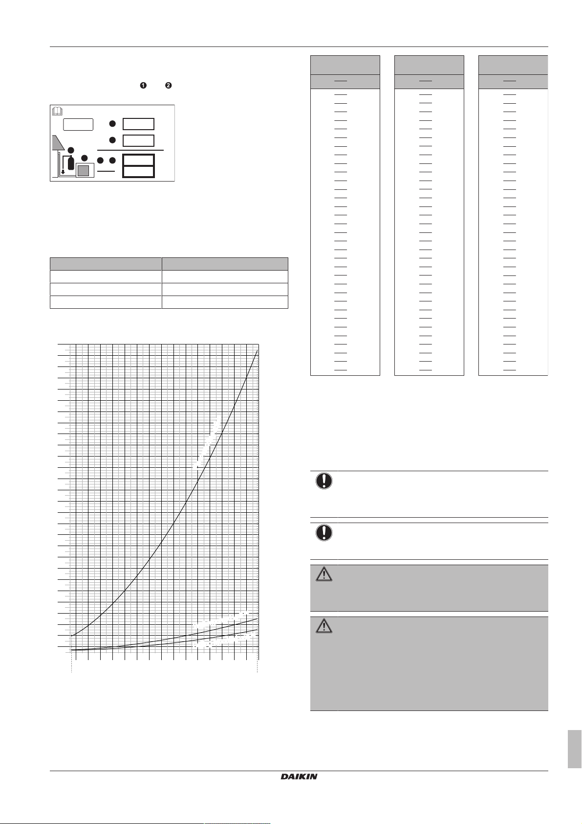
To determine the minimum floor area
Contains fluorinated greenhouse gases
2
1
1
1
2
2
kg
tCO2eq
1000
GWP × kg
=
=
+
kg
=
kg
=
GWP: xxx
R32
0
10
20
30
40
50
60
70
80
90
100
110
120
130
140
150
160
170
180
190
200
210
220
230
240
250
260
270
280
290
300
310
320
330
340
350
360
370
380
390
400
410
420
430
440
450
460
470
480
490
500
510
520
530
540
550
1.822.2
2.4
2.6
2.833.2
3.4
3.6
3.844.2
4.4
4.6
4.855.2
5.4
5.6
5.866.2
6.4
6.6
6.877.2
7.4
7.6
7.8
1.843 7.956
8.0
A
min
(m2)
Floor-standing unit
(c)
Wall-mounted unit
(b)
Ceiling-mounted unit
(a)
m (kg)
Ceiling-mounted
unit
(a)
4.6 13.4
4.6 180
4.8 14.6
4.8 196
5.0 15.8
5.0 213
≤1.842 —
5.2 17.1
≤1.842 —
5.2 230
1.843 3.64
5.4 18.5
1.843 28.9
5.4 248
2.0 3.95
5.6 19.9
2.0 34.0
5.6 267
2.2 4.34
5.8 21.3
2.2 41.2
5.8 286
2.4 4.74
6.0 22.8
2.4 49.0
6.0 306
2.6 5.13
6.2 24.3
2.6 57.5
6.2 327
2.8 5.53
6.4 25.9
2.8 66.7
6.4 349
3.0 5.92
6.6 27.6
3.0 76.6
6.6 371
3.2 6.48
6.8 29.3
3.2 87.2
6.8 394
3.4 7.32
7.0 31.0
3.4 98.4
7.0 417
3.6 8.20
7.2 32.8
3.6 110
7.2 441
3.8 9.14
7.4 34.7
3.8 123
7.4 466
4.0 10.1
7.6 36.6
4.0 136
7.6 492
4.2 11.2
7.8 38.5
4.2 150
7.8 518
4.4 12.3
7.956 40.1
4.4 165
7.956 539
m (kg)
A
min
(m2)
4.6 20.0
4.8 21.8
5.0 23.6
≤1.842 —
5.2 25.6
1.843 4.45
5.4 27.6
2.0 4.83
5.6 29.7
2.2 5.31
5.8 31.8
2.4 5.79
6.0 34.0
2.6 6.39
6.2 36.4
2.8 7.41
6.4 38.7
3.0 8.51
6.6 41.2
3.2 9.68
6.8 43.7
3.4 10.9
7.0 46.3
3.6 12.3
7.2 49.0
3.8 13.7
7.4 51.8
4.0 15.1
7.6 54.6
4.2 16.7
7.8 57.5
4.4 18.3
7.956 59.9
Wall-mounted
unit
(b)
m (kg)
A
min
(m2)
Floor-standing
unit
(c)
m (kg)
A
min
(m2)
1 Determine the total refrigerant charge in the system (=factory
refrigerant charge + additional refrigerant amount
charged).
2 Determine which graph or table to use.
▪ For indoor units: Is the unit ceiling-mounted, wall-mounted or
floor-standing?
▪ For outdoor units installed or stored indoors, and field piping
in unventilated spaces, this depends on the installation
height:
If the installation height is… Then use the graph or table for…
<1.8m Floor-standing units
1.8≤x<2.2m Wall-mounted units
≥2.2m Ceiling-mounted units
3 Use the graph or table to determine the minimum floor area.
1 General safety precautions
FXFQ20~125BVEB
VRV system air conditioner
4P561452-1 – 2018.12
m Total refrigerant charge in the system
A
Minimum floor area
min
(a) Ceiling-mounted unit (= Ceiling-mounted unit)
(b) Wall-mounted unit (= Wall-mounted unit)
(c) Floor-standing unit (= Floor-standing unit)
1.3.3 Refrigerant
If applicable. See the installation manual or installer reference guide
of your application for more information.
NOTICE
Make sure refrigerant piping installation complies with
applicable legislation. In Europe, EN378 is the applicable
standard.
NOTICE
Make sure the field piping and connections are NOT
subjected to stress.
WARNING
During tests, NEVER pressurize the product with a
pressure higher than the maximum allowable pressure (as
indicated on the nameplate of the unit).
WARNING
Take sufficient precautions in case of refrigerant leakage. If
refrigerant gas leaks, ventilate the area immediately.
Possible risks:
▪ Excessive refrigerant concentrations in a closed room
can lead to oxygen deficiency.
▪ Toxic gas may be produced if refrigerant gas comes
into contact with fire.
Installer and user reference guide
5
Page 6
1 General safety precautions
DANGER: RISK OF EXPLOSION
Pump down – Refrigerant leakage. If you want to pump
down the system, and there is a leak in the refrigerant
circuit:
▪ Do NOT use the unit's automatic pump down function,
with which you can collect all refrigerant from the
system into the outdoor unit. Possible consequence:
Self-combustion and explosion of the compressor
because of air going into the operating compressor.
▪ Use a separate recovery system so that the unit's
compressor does NOT have to operate.
WARNING
ALWAYS recover the refrigerant. Do NOT release them
directly into the environment. Use a vacuum pump to
evacuate the installation.
NOTICE
After all the piping has been connected, make sure there is
no gas leak. Use nitrogen to perform a gas leak detection.
NOTICE
▪ To avoid compressor breakdown, do NOT charge more
than the specified amount of refrigerant.
▪ When the refrigerant system is to be opened,
refrigerant MUST be treated according to the applicable
legislation.
WARNING
Make sure there is no oxygen in the system. Refrigerant
may only be charged after performing the leak test and the
vacuum drying.
▪ In case re-charge is required, refer to the nameplate of the unit. It
states the type of refrigerant and necessary amount.
▪ The unit is factory charged with refrigerant and depending on pipe
sizes and pipe lengths some systems require additional charging
of refrigerant.
▪ Only use tools exclusively for the refrigerant type used in the
system, this to ensure pressure resistance and prevent foreign
materials from entering into the system.
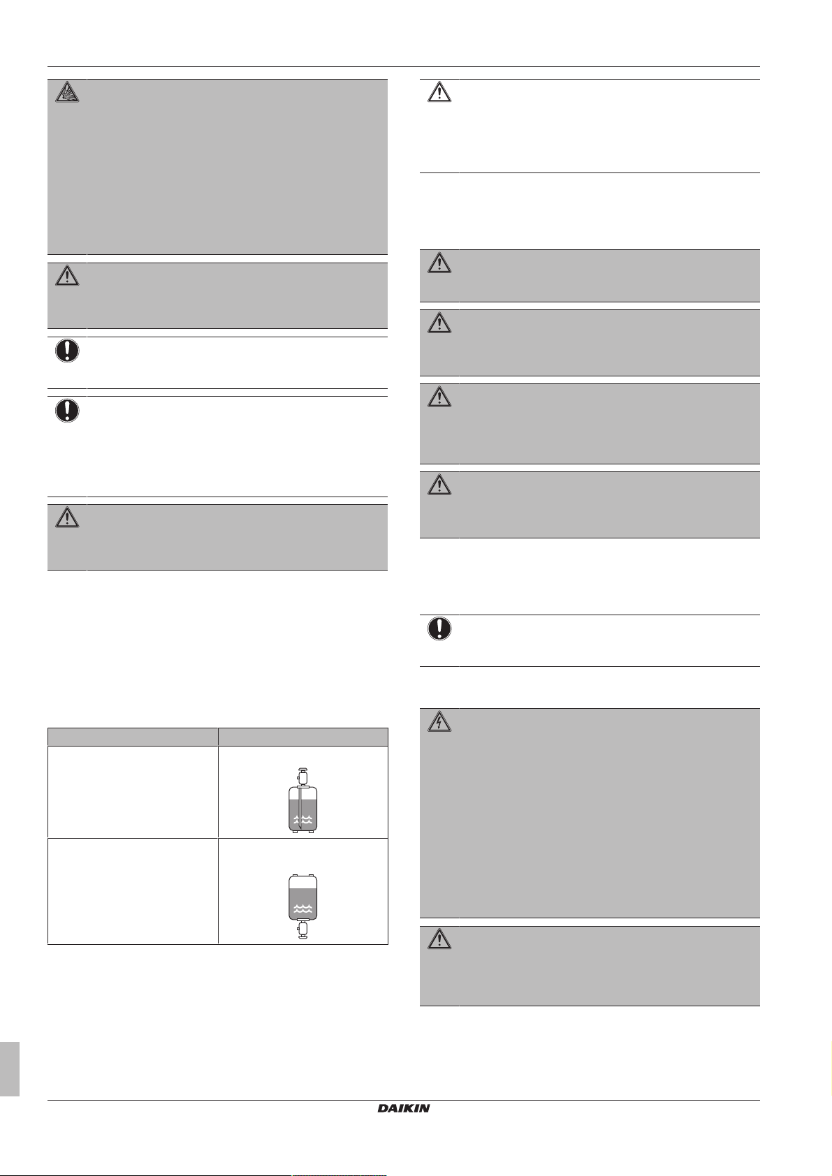
▪ Charge the liquid refrigerant as follows:
If Then
A siphon tube is present
(i.e., the cylinder is marked with
"Liquid filling siphon attached")
A siphon tube is NOT present Charge with the cylinder upside
Charge with the cylinder upright.
down.
CAUTION
When the refrigerant charging procedure is done or when
pausing, close the valve of the refrigerant tank
immediately. If the valve is NOT closed immediately,
remaining pressure might charge additional refrigerant.
Possible consequence: Incorrect refrigerant amount.
1.3.4 Brine
If applicable. See the installation manual or installer reference guide
of your application for more information.
WARNING
The selection of the brine MUST be in accordance with the
applicable legislation.
WARNING
Take sufficient precautions in case of brine leakage. If
brine leaks, ventilate the area immediately and contact
your local dealer.
WARNING
The ambient temperature inside the unit can get much
higher than that of the room, e.g. 70°C. In case of a brine
leak, hot parts inside the unit can create a hazardous
situation.
WARNING
The use and installation of the application MUST comply
with the safety and environmental precautions specified in
the applicable legislation.
1.3.5 Water
If applicable. See the installation manual or installer reference guide
of your application for more information.
NOTICE
Make sure water quality complies with EU directive
98/83EC.
1.3.6 Electrical
DANGER: RISK OF ELECTROCUTION
▪ Turn OFF all power supply before removing the
switch box cover, connecting electrical wiring or
touching electrical parts.
▪ Disconnect the power supply for more than 1 minute,
and measure the voltage at the terminals of main circuit
capacitors or electrical components before servicing.
The voltage MUST be less than 50 V DC before you
can touch electrical components. For the location of the
terminals, see the wiring diagram.
▪ Do NOT touch electrical components with wet hands.
▪ Do NOT leave the unit unattended when the service
cover is removed.
▪ Open refrigerant cylinders slowly.
▪ Charge the refrigerant in liquid form. Adding it in gas form may
prevent normal operation.
Installer and user reference guide
6
WARNING
If NOT factory installed, a main switch or other means for
disconnection, having a contact separation in all poles
providing full disconnection under overvoltage category III
condition, MUST be installed in the fixed wiring.
FXFQ20~125BVEB
VRV system air conditioner
4P561452-1 – 2018.12
Page 7
2 About the documentation
WARNING
▪ ONLY use copper wires.
▪ Make sure the field wiring complies with the applicable
legislation.
▪ All field wiring MUST be performed in accordance with
the wiring diagram supplied with the product.
▪ NEVER squeeze bundled cables and make sure they
do NOT come in contact with the piping and sharp
edges. Make sure no external pressure is applied to the
terminal connections.
▪ Make sure to install earth wiring. Do NOT earth the unit
to a utility pipe, surge absorber, or telephone earth.
Incomplete earth may cause electrical shock.
▪ Make sure to use a dedicated power circuit. NEVER
use a power supply shared by another appliance.
▪ Make sure to install the required fuses or circuit
breakers.
▪ Make sure to install an earth leakage protector. Failure
to do so may cause electric shock or fire.
▪ When installing the earth leakage protector, make sure
it is compatible with the inverter (resistant to high
frequency electric noise) to avoid unnecessary opening
of the earth leakage protector.
CAUTION
When connecting the power supply, the earth connection
must be made before the current-carrying connections are
established. When disconnecting the power supply, the
current-carrying connections must be separated before the
earth connection is. The length of the conductors between
the power supply stress relief and the terminal block itself
must be as such that the current-carrying wires are
tautened before the earth wire is in case the power supply
is pulled loose from the stress relief.
NOTICE
Precautions when laying power wiring:
▪ Do NOT connect wiring of different thicknesses to the
power terminal block (slack in the power wiring may
cause abnormal heat).
▪ When connecting wiring which is the same thickness,
do as shown in the figure above.
▪ For wiring, use the designated power wire and connect
firmly, then secure to prevent outside pressure being
exerted on the terminal board.
▪ Use an appropriate screwdriver for tightening the
terminal screws. A screwdriver with a small head will
damage the head and make proper tightening
impossible.
▪ Over-tightening the terminal screws may break them.
WARNING
▪ After finishing the electrical work, confirm that each
electrical component and terminal inside the electrical
components box is connected securely.
▪ Make sure all covers are closed before starting up the
unit.
NOTICE
Only applicable if the power supply is three‑phase, and the
compressor has an ON/OFF starting method.
If there exists the possibility of reversed phase after a
momentary black out and the power goes on and off while
the product is operating, attach a reversed phase
protection circuit locally. Running the product in reversed
phase can break the compressor and other parts.
2 About the documentation
2.1 About this document
Target audience
Authorised installers + end users
INFORMATION
This appliance is intended to be used by expert or trained
users in shops, in light industry and on farms, or for
commercial use by lay persons.
Documentation set
This document is part of a documentation set. The complete set
consists of:
▪ General safety precautions:
▪ Safety instructions that you must read before installing
▪ Format: Paper (in the box of the indoor unit)
▪ Indoor unit installation and operation manual:
▪ Installation and operation instructions
▪ Format: Paper (in the box of the indoor unit)
▪ Installer and user reference guide:
▪ Preparation of the installation, good practices, reference data,…
▪ Detailed step-by-step instructions and background information
for basic and advanced usage
▪ Format: Digital files on http://www.daikineurope.com/support-
and-manuals/product-information/
Latest revisions of the supplied documentation may be available on
the regional Daikin website or via your dealer.
The original documentation is written in English. All other languages
are translations.
Technical engineering data
▪ A subset of the latest technical data is available on the regional
Daikin website (publicly accessible).
▪ The full set of latest technical data is available on the Daikin
extranet (authentication required).
FXFQ20~125BVEB
VRV system air conditioner
4P561452-1 – 2018.12
Installer and user reference guide
7
Page 8
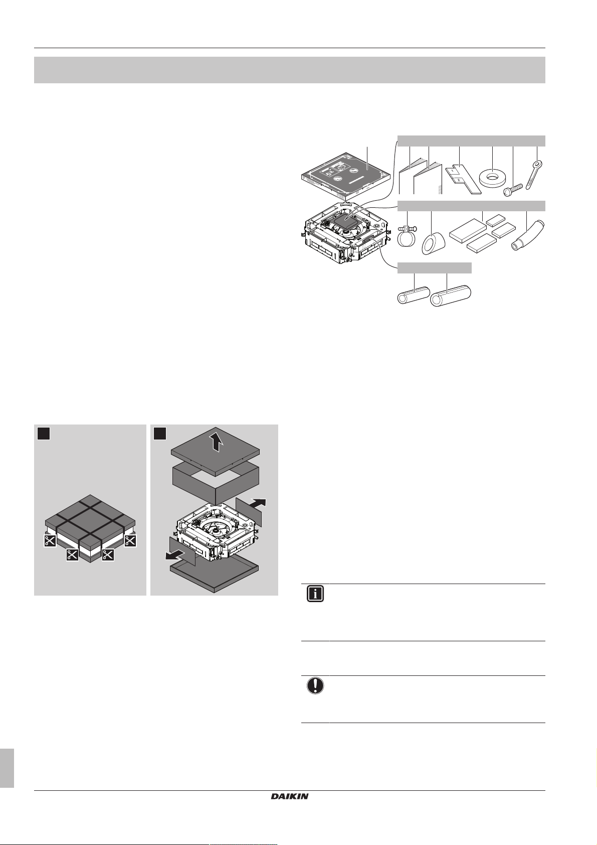
3 About the box
1 2
8× 4×1×1× 1×
a
4×1×
1×
1×
1×
7×
1×
e fdcb
h ji
g
k
l m
For the installer
3 About the box
3.1 Overview: About the box
This chapter describes what you have to do after the box with the
indoor unit is delivered on-site.
It contains information about:
▪ Unpacking and handling the unit
▪ Removing the accessories from the unit
Keep the following in mind:
▪ At delivery, the unit MUST be checked for damage. Any damage
MUST be reported immediately to the carrier's claims agent.
▪ Bring the packed unit as close as possible to its final installation
position to prevent damage during transport.
▪ Prepare the path along which you want to bring the unit inside in
advance.
3.2 Indoor unit
3.2.1 To unpack and handle the unit
Use a sling of soft material or protective plates together with a rope
when lifting the unit. This to avoid damage or scratches to the unit.
Lift the unit by holding on to the hanger brackets without exerting
any pressure on other parts, especially on refrigerant piping, drain
piping and other resin parts.
3.2.2 To remove the accessories from the indoor unit
a Paper pattern for installation (upper part of packing)
b General safety precautions
c Indoor unit installation and operation manual
d Installation guide
e Washers for hanger brackets
f Screws (to temporarily attach the paper pattern for
installation to the indoor unit)
g Cable ties
h Metal clamp
i Insulation piece (drain pipe)
j Sealing pads: Large (drain pipe), medium 1 (gas pipe),
medium 2 (liquid pipe), small (electrical wiring)
k Drain hose
l Insulation piece: Small (liquid pipe)
m Insulation piece: Large (gas pipe)
4 About the units and options
4.1 Overview: About the units and options
This chapter contains information about:
▪ Identifying the indoor unit
▪ Combining outdoor and indoor units
▪ Combining the indoor unit with options
INFORMATION
For year‑round cooling applications with low indoor
humidity conditions, such as Electronic Data Processing
rooms, contact your dealer or see the engineering
databook or the service manual.
4.2 Identification
NOTICE
When installing or servicing several units at the same time,
make sure NOT to switch the service panels between
different models.
Installer and user reference guide
8
FXFQ20~125BVEB
VRV system air conditioner
4P561452-1 – 2018.12
Page 9
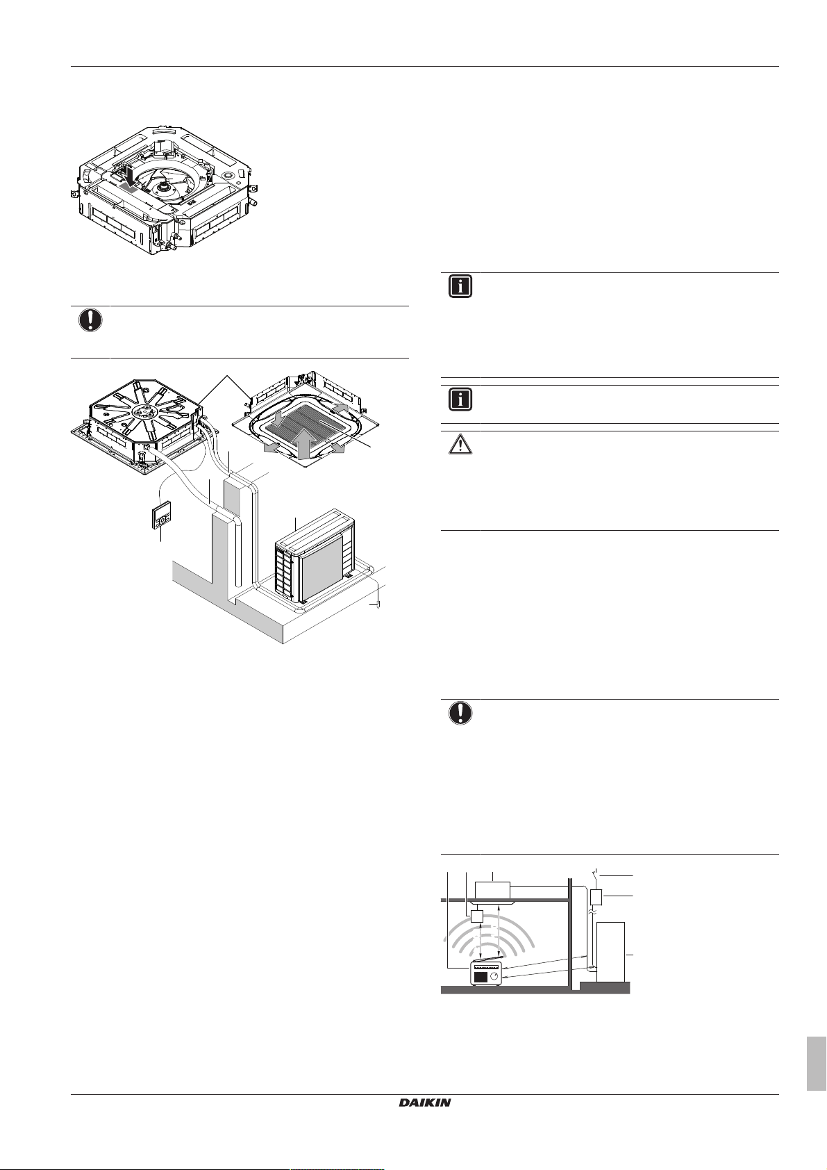
5 Preparation
a
b
c
d
e
i
f
g
h
b
a
c
df e
(mm)
≥
1500
≥
1500
≥
1000≥1000
≥
1000≥1000
4.2.1 Identification label: Indoor unit
Location
4.3 System layout
NOTICE
Design of the system must not be done at temperatures
below –15°C.
a Indoor unit
b Outdoor unit
c User interface
d Suction air
e Discharge air
f Refrigerant piping + interconnection cable
g Drain pipe
h Earth wiring
i Suction grille and air filter
4.4 Combining units and options
4.4.1 Possible options for the indoor unit
Make sure you have the following mandatory options:
▪ User interface: Wired or wireless
▪ Decoration panel: Standard, self-cleaning or design
▪ Preparing the electrical wiring
5.2 Preparing the installation site
Do NOT install the unit in places often used as work place. In case
of construction works (e.g. grinding works) where a lot of dust is
created, the unit MUST be covered.
Choose an installation location with sufficient space for carrying the
unit in and out of the site.
5.2.1 Installation site requirements of the indoor unit
INFORMATION
Also read the following requirements:
▪ General installation site requirements. See the
"General safety precautions" chapter.
▪ Refrigerant piping requirements (length, height
difference). See further in this "Preparation" chapter.
INFORMATION
The sound pressure level is less than 70dBA.
CAUTION
Appliance not accessible to the general public, install it in a
secured area, protected from easy access.
This unit, both indoor and outdoor, is suitable for
installation in a commercial and light industrial
environment.
Do NOT install the unit in the following places:
▪ In places where a mineral oil mist, spray or vapour may be
present in the atmosphere. Plastic parts may deteriorate and fall
off or cause water leakage.
It is NOT recommended to install the unit in the following places
because it may shorten the life of the unit:
▪ Where the voltage fluctuates a lot
▪ In vehicles or vessels
▪ Where acidic or alkaline vapour is present
NOTICE
The equipment described in this manual may cause
electronic noise generated from radio-frequency energy.
The equipment complies to specifications that are
designed to provide reasonable protection against such
interference. However, there is no guarantee that
interference will not occur in a particular installation.
It is therefore recommended to install the equipment and
electric wires keeping proper distances away from stereo
equipment, personal computers, etc.
5 Preparation
5.1 Overview: Preparation
This chapter describes what you have to do and know before going
on-site.
It contains information about:
▪ Preparing the installation site
▪ Preparing the refrigerant piping
FXFQ20~125BVEB
VRV system air conditioner
4P561452-1 – 2018.12
a Earth leakage protector
b Fuse
c Outdoor unit
d Indoor unit
e User interface
f Personal computer or radio
Installer and user reference guide
9
Page 10
5 Preparation
1
2
3
4
1
2
3
4
1
2
3
a b c
(mm)
≥1500
≥
2000
≥
4000
≥1500
A
B
C
ba dac
≥1500 ≥500 ≥200
a
A A A
b c
t
Ø
In places with weak reception, keep distances of 3 m or more to
avoid electromagnetic disturbance of other equipment and use
conduit tubes for power and transmission lines.
▪ Fluorescent lights. When installing a wireless user interface in a
room with fluorescent lights, mind the following to avoid
interference:
▪ Install the wireless user interface as close as possible to the
indoor unit.
▪ Install the indoor unit as far as possible from the fluorescent
lights.
▪ Take care that in the event of a water leak, water cannot cause
any damage to the installation space and surroundings.
▪ Choose a location where the hot/cold air discharged from the unit
or the operation noise, will NOT disturb anyone.
▪ Air flow. Make sure nothing blocks the air flow.
▪ Drainage. Make sure condensation water can be evacuated
properly.
▪ Paper pattern for installation (upper part of packing)
(accessory). When selecting the installation location, use the
paper pattern. It contains the dimensions of the unit and the
required ceiling opening.
▪ Air flow directions. You can select different air flow directions.
Choose the one best suited for the room. Also make sure the "Air
flow direction" field setting corresponds with the actual situation
(see "7.1Field settings"on page17).
Example:
≥298mm: In case of installation with standard decoration
panel
≥340mm: In case of installation with design decoration
panel
≥348mm: In case of installation with fresh air intake kit
≥378mm: In case of installation with self-cleaning
decoration panel
a Indoor unit
b Lighting (the figure shows ceiling-mounted lighting, but
recessed lighting is also allowed)
c Air fan
d Static volume (example: table)
▪ A: Minimum distance to the wall. Depends on the air flow
directions towards the wall.
a Air outlet and corners open
b Air outlet closed, corners open (optional blocking pad kit
required)
c Air outlet and corners closed (optional blocking pad kit
required)
▪ B: Minimum and maximum distance to the floor:
▪ Minimum: 2.7m to avoid accidental touching.
▪ Maximum: Depends on the air flow directions and the capacity
class. Also make sure the "Ceiling height" field setting
corresponds with the actual situation. See "7.1 Field
settings"on page17.
a All-round air flow
b 4-way air flow (with closed corners) (optional blocking pad
kit required)
c 3-way air flow (optional blocking pad kit required)
▪ Ceiling insulation. When conditions in the ceiling exceed 30°C
and a relative humidity of 80%, or when fresh air is inducted into
the ceiling, then additional insulation is required (minimum 10mm
thickness, polyethylene foam).
▪ Spacing. Mind the following requirements:
A Minimum distance to the wall (see below)
B Minimum and maximum distance to the floor (see below)
C 20~63 class:
≥214mm: In case of installation with standard decoration
panel
≥256mm: In case of installation with design decoration
panel
≥294mm: In case of installation with self-cleaning
decoration panel
≥263mm: In case of installation with fresh air intake kit
80~100 class:
≥256mm: In case of installation with standard decoration
panel
≥298mm: In case of installation with design decoration
panel
≥306mm: In case of installation with fresh air intake kit
≥316mm: In case of installation with self-cleaning
decoration panel
125 class:
If air flow direction… Then B
FXFQ20~100 FXFQ125
All-round ≤3.5m ≤4.2m
(a)
4-way
3-way
(a)
(a) Optional blocking kit required
≤4.0m ≤4.5m
≤3.5m ≤4.2m
5.3 Preparing refrigerant piping
5.3.1 Refrigerant piping requirements
INFORMATION
Also read the precautions and requirements in the
"General safety precautions" chapter.
Refrigerant piping diameter
Use the same diameters as the connections on the outdoor units:
Class L1 liquid piping L1 gas piping
20~50 Ø6.4mm Ø12.7mm
63~125 Ø9.5mm Ø15.9mm
Refrigerant piping material
▪ Piping material: Phosphoric acid deoxidised seamless copper.
▪ Flare connections: Only use annealed material.
▪ Piping temper grade and thickness:
Outer diameter
Temper grade Thickness (t)
(Ø)
6.4mm (1/4") Annealed (O) ≥0.8mm
9.5mm (3/8")
12.7mm (1/2")
15.9mm (5/8")
(a)
Installer and user reference guide
10
FXFQ20~125BVEB
VRV system air conditioner
4P561452-1 – 2018.12
Page 11

6 Installation
A
c
b
d
e
a
(a) Depending on the applicable legislation and the unit's
maximum working pressure (see "PS High" on the unit
name plate), larger piping thickness might be required.
5.3.2 Refrigerant piping insulation
▪ Use polyethylene foam as insulation material:
▪ with a heat transfer rate between 0.041 and 0.052W/mK (0.035
and 0.045kcal/mh°C)
▪ with a heat resistance of at least 120°C
▪ Insulation thickness
Ambient
temperature
≤30°C 75% to 80% RH 15mm
>30°C ≥80% RH 20mm
Humidity Minimum thickness
5.4 Preparing electrical wiring
5.4.1 About preparing electrical wiring
INFORMATION
Also read the precautions and requirements in the
"General safety precautions" chapter.
WARNING
▪ If the power supply has a missing or wrong N-phase,
equipment might break down.
▪ Establish proper earthing. Do NOT earth the unit to a
utility pipe, surge absorber, or telephone earth.
Incomplete earthing may cause electrical shock.
▪ Install the required fuses or circuit breakers.
▪ Secure the electrical wiring with cable ties so that the
cables do NOT come in contact with sharp edges or
piping, particularly on the high-pressure side.
▪ Do NOT use taped wires, stranded conductor wires,
extension cords, or connections from a star system.
They can cause overheating, electrical shock or fire.
▪ Do NOT install a phase advancing capacitor, because
this unit is equipped with an inverter. A phase
advancing capacitor will reduce performance and may
cause accidents.
WARNING
▪ All wiring MUST be performed by an authorised
electrician and MUST comply with the applicable
legislation.
▪ Make electrical connections to the fixed wiring.
▪ All components procured on-site and all electrical
construction MUST comply with the applicable
legislation.
WARNING
ALWAYS use multicore cable for power supply cables.
6 Installation
Typical workflow
Installation typically consists of the following stages:
1 Mounting the outdoor unit.
2 Mounting the indoor unit (+ decoration panel).
3 Connecting the refrigerant piping.
4 Checking the refrigerant piping.
5 Charging refrigerant.
6 Connecting the electrical wiring.
7 Finishing the outdoor installation.
8 Finishing the indoor installation.
INFORMATION
This chapter only describes installation instructions specific
to the indoor unit. For the other instructions, see:
▪ The installation manual of the outdoor unit
▪ The installation manual of the user interface
▪ The installation manual of the decoration panel
NOTICE
After installing the decoration panel:
▪ Make sure there is no gap between the unit body and
the decoration panel. Possible consequence: Air
might leak and cause dew drop.
▪ Make sure no oil remains on the plastic parts of the
decoration panel. Possible consequence:
Degradation and damage of plastic parts.
6.2 Mounting the indoor unit
6.2.1 Precautions when mounting the indoor unit
INFORMATION
Also read the precautions and requirements in the
following chapters:
▪ General safety precautions
▪ Preparation
6.2.2 Guidelines when installing the indoor unit
INFORMATION
Optional equipment. When installing optional equipment,
also read the installation manual of the optional equipment.
Depending on the field conditions, it might be easier to
install the optional equipment first.
▪ In case of installation with a fresh air intake kit. Install the
fresh air intake kit always before installing the unit.
▪ Decoration panel. Install the decoration panel always after
installing the unit.
▪ Ceiling strength. Check whether the ceiling is strong enough to
support the weight of the unit. If there is a risk, reinforce the ceiling
before installing the unit.
▪ For existing ceilings, use anchors.
▪ For new ceilings, use sunken inserts, sunken anchors or other
field supplied parts.
6.1 Overview: Installation
This chapter describes what you have to do and know on-site to
install the system.
FXFQ20~125BVEB
VRV system air conditioner
4P561452-1 – 2018.12
A 50~100mm: In case of installation with standard panel
Installer and user reference guide
11
Page 12

6 Installation
(mm)
780
710
a1
b
b
a2
c
4×
a cb d
(mm)
710
840
860~910
950
c
d
e
f
780
840
860~910
950
cde
f
a
b
A
C
B
2
1
2
1
2
1
2
1
A B
1
1
2
C
a
b c
2
1
2
D
c
bba
100~150mm: In case of installation with fresh air intake kit
or design panel
130~180mm: In case of installation with self-cleaning
decoration panel
a Ceiling slab
b Anchor
c Long nut or turnbuckle
d Suspension bolt
e Suspended ceiling
▪ Suspension bolts. Use M8~M10 suspension bolts for installation.
Attach the hanger bracket to the suspension bolt. Fix it securely
using a nut and washer from the upper and lower sides of the
hanger bracket.
a1 Nut (field supply)
a2 Double nut (field supply)
b Washer (accessories)
c Hanger bracket (attached to the unit)
▪ Paper pattern for installation (upper part of the packing). Use
the paper pattern to determine the correct horizontal positioning. It
contains the necessary dimensions and centers. You can attach
the paper pattern to the unit.
d Unit
e Ceiling opening
f Decoration panel
If A Then
B C
≥860mm 10mm 45mm
≤910mm 35mm 20mm
A Ceiling opening
B Distance between the unit and the ceiling opening
C Overlap between the decoration panel and the suspended
ceiling
▪ Installation guide. Use the installation guide to determine the
correct vertical position.
a Centre of the unit
b Centre of the ceiling opening
c Paper pattern for installation (upper part of the packing)
d Screws (accessories)
▪ Ceiling opening and unit:
▪ Make sure the ceiling opening is within the following limits:
Minimum: 860mm to be able to fit the unit.
Maximum: 910 mm to ensure enough overlap between the
decoration panel and the suspended ceiling. If the ceiling
opening is larger, add extra ceiling material.
▪ Make sure the unit and its hanger brackets (suspension) are
centered within the ceiling opening.
Installer and user reference guide
12
a Drain piping
b Refrigerant piping
c Hanger bracket pitch (suspension)
A In case of installation with standard decoration panel
B In case of installation with fresh air intake kit
C In case of installation with self-cleaning decoration panel
D In case of installation with design decoration panel
a Suspended ceiling
b Installation guide (accessory)
c Unit
▪ Level. Make sure the unit is level at all 4 corners using a level or a
water-filled vinyl tube.
a Level
b Vinyl tube
c Water level
NOTICE
Do NOT install the unit tilted. Possible consequence: If
the unit is tilted against the direction of the condensate flow
(the drain piping side is raised), the float switch might
malfunction and cause water to drip.
6.2.3 Guidelines when installing the drain piping
Make sure condensation water can be evacuated properly. This
involves:
▪ General guidelines
▪ Connecting the drain piping to the indoor unit
▪ Checking for water leaks
FXFQ20~125BVEB
VRV system air conditioner
4P561452-1 – 2018.12
Page 13

6 Installation
1~1.5 m
a
≤675
≤300
0~75
1000~1500
(mm)
ba
b c
a
dd
≥100
≤675
(mm)
a
≤4 mm
A
A'
A-A'
A
A'
f
652
ce
4
ba
d
b
a
d
c
3
1
2~61
b
a
c
N L
General guidelines
▪ Pipe length. Keep drain piping as short as possible.
▪ Pipe size. Keep the pipe size equal to or greater than that of the
connecting pipe (vinyl pipe of 25 mm nominal diameter and
32mm outer diameter).
▪ Slope. Make sure the drain piping slopes down (at least 1/100) to
prevent air from being trapped in the piping. Use hanging bars as
shown.
a Hanging bar
O Allowed
X Not allowed
▪ Rising piping. If necessary to make the slope possible, you can
install rising piping.
▪ Drain hose inclination: 0~75mm to avoid stress on the piping
and to avoid air bubbles.
▪ Rising piping: ≤300mm from the unit, ≤675mm perpendicular
to the unit.
a Metal clamp (accessory)
b Drain hose (accessory)
c Rising drain piping (vinyl pipe of 25mm nominal diameter
and 32mm outer diameter) (field supply)
d Hanging bars (field supply)
▪ Condensation. Take measures against condensation. Insulate
the complete drain piping in the building.
▪ Combining drain pipes. You can combine drain pipes. Make
sure to use drain pipes and T-joints with a correct gauge for the
operating capacity of the units.
4 Install the insulation piece (drain pipe).
5 Wind the large sealing pad (= insulation) around the metal
clamp and drain hose, and fix it with cable ties.
6 Connect the drain piping to the drain hose.
a Drain pipe connection (attached to the unit)
b Drain hose (accessory)
c Metal clamp (accessory)
d Large sealing pad (accessory)
e Insulation piece (drain pipe) (accessory)
f Drain piping (field supply)
To check for water leaks
The procedure differs depending on whether electrical wiring is
already finished. When electrical wiring is not finished yet, you need
to temporarily connect the user interface and power supply to the
unit.
When electrical wiring is not finished yet
1 Temporarily connect electrical wiring.
▪ Remove the switch box cover (a).
▪ Connect the user interface and transmission wiring (b).
▪ Connect the power supply (1~ 220-240 V 50/60 Hz) and
earth (c).
▪ Reattach the switch box cover (a).
a T-joint
To connect the drain piping to the indoor unit
NOTICE
Incorrect connection of the drain hose might cause leaks,
and damage the installation space and surroundings.
1 Push the drain hose as far as possible over the drain pipe
connection.
2 Tighten the metal clamp until the screw head is less than 4mm
from the metal clamp part.
3 Check for water leaks (see "To check for water leaks" on
page13).
FXFQ20~125BVEB
VRV system air conditioner
4P561452-1 – 2018.12
2 Turn ON the power.
3 Start cooling operation (see "8.4 To perform a test run" on
page19).
4 Gradually pour approximately 1 l of water through the air
discharge outlet, and check for leaks.
Installer and user reference guide
13
Page 14

6 Installation
≥100 mm
e
d
c
b
a
a Plastic watering can
b Service drain outlet (with rubber plug). Use this outlet to
drain water from the drain pan.
c Drain pump location
d Drain pipe connection
e Drain pipe
5 Turn OFF the power.
6 Disconnect the electrical wiring.
▪ Remove the switch box cover.
▪ Disconnect the power supply and earth.
▪ Disconnect the user interface.
▪ Reattach the switch box cover.
When electrical wiring is finished already
1 Start cooling operation (see "8.4 To perform a test run" on
page19).
2 Gradually pour approximately 1 l of water through the air
discharge outlet, and check for leaks (see "When electrical
wiring is not finished yet"on page13).
CAUTION
▪ Do NOT use mineral oil on flared part.
▪ Do NOT reuse piping from previous installations.
▪ NEVER install a drier to this R410A unit to guarantee
its lifetime. The drying material may dissolve and
damage the system.
NOTICE
Take the following precautions on refrigerant piping into
account:
▪ Avoid anything but the designated refrigerant to get
mixed into the refrigerant cycle (e.g. air).
▪ Only use R410A when adding refrigerant.
▪ Only use installation tools (e.g. manifold gauge set) that
are exclusively used for R410A installations to
withstand the pressure and to prevent foreign materials
(e.g. mineral oils and moisture) from mixing into the
system.
▪ Install the piping so that the flare is NOT subjected to
mechanical stress
▪ Protect the piping as described in the following table to
prevent dirt, liquid or dust from entering the piping.
▪ Use caution when passing copper tubes through walls
(see figure below).
6.3 Connecting the refrigerant piping
6.3.1 About connecting the refrigerant piping
Before connecting the refrigerant piping
Make sure the outdoor and indoor unit are mounted.
Typical workflow
Connecting the refrigerant piping involves:
▪ Connecting the refrigerant piping to the indoor unit
▪ Connecting the refrigerant piping to the outdoor unit
▪ Insulating the refrigerant piping
▪ Keeping in mind the guidelines for:
▪ Pipe bending
▪ Flaring pipe ends
▪ Using the stop valves
6.3.2 Precautions when connecting the refrigerant piping
INFORMATION
Also read the precautions and requirements in the
following chapters:
▪ General safety precautions
▪ Preparation
DANGER: RISK OF BURNING
Unit Installation period Protection method
Outdoor unit >1month Pinch the pipe
<1month Pinch or tape the pipe
Indoor unit Regardless of the
period
INFORMATION
Do NOT open the refrigerant stop valve before checking
the refrigerant piping. When you need to charge additional
refrigerant it is recommended to open the refrigerant stop
valve after charging.
6.3.3 Guidelines when connecting the refrigerant piping
Take the following guidelines into account when connecting pipes:
▪ Coat the flare inner surface with ether oil or ester oil when
connecting a flare nut. Tighten 3 or 4 turns by hand, before
tightening firmly.
▪ ALWAYS use 2 wrenches together when loosening a flare nut.
▪ ALWAYS use a spanner and torque wrench together to tighten the
flare nut when connecting the piping. This to prevent nut cracking
and leaks.
Installer and user reference guide
14
FXFQ20~125BVEB
VRV system air conditioner
4P561452-1 – 2018.12
Page 15

a
b
c
d
a Torque wrench
R=0.4~0.8
45°
±2
90°
±2
A
a b
A
a b
c
A B
a dc e fb b
a dc e fb b
2
4
3
g
1
23
4
g
AB
1
b Spanner
c Piping union
d Flare nut
Piping size
(mm)
Tightening
torque (N•m)
Flare
dimensions (A)
Flare shape
(mm)
(mm)
Ø6.4 15~17 8.7~9.1
Ø9.5 33~39 12.8~13.2
Ø12.7 50~60 16.2~16.6
Ø15.9 63~75 19.3~19.7
6.3.4 Pipe bending guidelines
Use a pipe bender for bending. All pipe bends should be as gentle
as possible (bending radius should be 30~40mm or larger).
6.3.5 To flare the pipe end
6 Installation
6.3.6 To connect the refrigerant piping to the indoor unit
CAUTION
Install the refrigerating piping or components in a position
where they are unlikely to be exposed to any substance
which may corrode components containing refrigerant,
unless the components are constructed of materials that
are inherently resistant to corrosion or are suitably
protected against corrosion.
▪ Pipe length. Keep refrigerant piping as short as possible.
▪ Flare connections. Connect refrigerant piping to the unit using
flare connections.
▪ Insulation. Insulate the refrigerant piping on the indoor unit as
follows:
CAUTION
▪ Incomplete flaring may cause refrigerant gas leakage.
▪ Do NOT re-use flares. Use new flares to prevent
refrigerant gas leakage.
▪ Use flare nuts that are included with the unit. Using
different flare nuts may cause refrigerant gas leakage.
1 Cut the pipe end with a pipe cutter.
2 Remove burrs with the cut surface facing down so that the
chips do NOT enter the pipe.
a Cut exactly at right angles.
b Remove burrs.
3 Remove the flare nut from the stop valve and put the flare nut
on the pipe.
4 Flare the pipe. Set exactly at the position as shown in the
following figure.
Flare tool for
R410A (clutch
type)
Conventional flare tool
Clutch type
(Ridgid-type)
Wing nut type
(Imperial-type)
A 0~0.5mm 1.0~1.5mm 1.5~2.0mm
5 Check that the flaring is properly made.
A Gas piping
B Liquid piping
a Insulation material (field supply)
b Cable tie (accessory)
c Insulation pieces: Large (gas pipe), small (liquid pipe)
(accessories)
d Flare nut (attached to the unit)
e Refrigerant pipe connection (attached to the unit)
f Unit
g Sealing pads: Medium 1 (gas pipe), medium 2 (liquid pipe)
(accessories)
1 Turn up the seams of the insulation pieces.
2 Attach to the base of the unit.
3 Tighten the cable ties on the insulation pieces.
4 Wrap the sealing pad from the base of the unit to the top of
the flare nut.
NOTICE
Make sure to insulate all refrigerant piping. Any exposed
piping might cause condensation.
6.4 Connecting the electrical wiring
6.4.1 About connecting the electrical wiring
Typical workflow
Connecting the electrical wiring typically consists of the following
stages:
1 Making sure the power supply system complies with the
electrical specifications of the units.
2 Connecting the electrical wiring to the outdoor unit.
3 Connecting the electrical wiring to the indoor unit.
4 Connecting the main power supply.
a Flare’s inner surface MUST be flawless.
b The pipe end MUST be evenly flared in a perfect circle.
c Make sure the flare nut is fitted.
FXFQ20~125BVEB
VRV system air conditioner
4P561452-1 – 2018.12
Installer and user reference guide
15
Page 16

6 Installation
b a
c b
c
aa
A
AA´
A´
c b ba c
a
B
B
6.4.2 Precautions when connecting the electrical wiring
INFORMATION
Also read the precautions and requirements in the
following chapters:
▪ General safety precautions
▪ Preparation
DANGER: RISK OF ELECTROCUTION
WARNING
ALWAYS use multicore cable for power supply cables.
WARNING
Use an all-pole disconnection type breaker with at least
3 mm between the contact point gaps that provide full
disconnection under overvoltage category III.
WARNING
If the supply cord is damaged, it MUST be replaced by the
manufacturer, its service agent or similarly qualified
persons in order to avoid a hazard.
6.4.3 Guidelines when connecting the electrical wiring
Keep the following in mind:
▪ If stranded conductor wires are used, install a round crimp-style
terminal on the end of the wire. Place the round crimp-style
terminal on the wire up to the covered part and fasten the terminal
with the appropriate tool.
Tightening torques
Wiring Screw size Tightening torque
(N•m)
Interconnection cable
(indoor↔outdoor)
User interface cable M3.5 0.79~0.97
M4 1.18~1.44
6.4.4 Specifications of standard wiring components
Component Class
20~40 50 63 80 100 125
Power
supply cable
Interconnection cable 4-core cable 1.5mm2~2.5mm2 and
User interface cable Vinyl cords with 0.75 to 1.25mm² sheath
Recommended field fuse 16A
Earth leakage circuit
breaker
(a)
MCA
Voltage 220~240V
Phase 1~
Frequency 50/60Hz
Wire sizes Must comply with applicable legislation
(a) MCA=Minimum circuit ampacity. Stated values are
maximum values (see electrical data of combination with
indoor units for exact values).
0.5A 0.6A 0.7A 1.2A1.3A 1.4A
applicable for 220~240V
H05RN-F (60245 IEC 57)
or cables (2‑core wires)
Maximum 500m
H03VV-F (60227 IEC 52)
Must comply with applicable legislation
a Stranded conductor wire
b Round crimp-style terminal
▪ Use the following methods for installing wires:
Wire type Installation method
Single-core wire
a Curled single-core wire
b Screw
c Flat washer
Stranded conductor
wire with round
crimp-style terminal
a Terminal
b Screw
c Flat washer
O Allowed
X NOT allowed
6.4.5 To connect the electrical wiring on the indoor unit
NOTICE
▪ Follow the wiring diagram (delivered with the unit,
located at the inside of the service cover).
▪ For instructions on how to connect the decoration panel
and the sensor kit, see the installation manual delivered
with the panel or the kit.
▪ Make sure the electrical wiring does NOT obstruct
proper reattachment of the service cover.
It is important to keep the power supply and the transmission wiring
separated from each other. In order to avoid any electrical
interference the distance between both wirings should ALWAYS be
at least 50mm.
NOTICE
Be sure to keep the power line and transmission line apart
from each other. Transmission wiring and power supply
wiring may cross, but may NOT run parallel.
1 Remove the service cover.
2 User interface cable: Route the cable through the frame,
connect the cable to the terminal block, and fix the cable with a
cable tie.
3 Interconnection cable (indoor↔outdoor): Route the cable
through the frame, connect the cable to the terminal block
(make sure the numbers match with the numbers on the
outdoor unit, and connect the earth wire), and fix the cable with
a cable tie.
Installer and user reference guide
16
FXFQ20~125BVEB
VRV system air conditioner
4P561452-1 – 2018.12
Page 17

4 Divide the small sealing (accessory) and wrap it around the
a
b
c
d
e
f
h
g
i
IN/D OUT/D
F
1 F2
Control box
F1 F2
LN
P1P
2
P1P
2
F1F2T1T
2
P1P
2
P1P
2
LN
F1F2T1T
2
P1P
2
P1P
2
LN
F1F2T1T
2 LNP1P2
P1P
2
F1F2T1T
2
LN
L N L N L N
d
b
c
a
a
IN/D OUT/D
F
1 F2 F1 F2
Control box
LN
P1P
2
P1P
2
F1F2T1T
2 LNP1P2F1F2T1T2 LNP1P2F1F2T1T2
P1P
2
LN
P1P2F1F2T1T
2
P1P
2
d
b
c
e
L N
IN/D OUT/D
F
1 F2 F1 F2
Control box
IN/DOUT/D
F
1 F2 F1 F2
Control box
P1P
2
LN
P1P2F1F2T1T
2
a
f
b
c
L
N
a
(mm)
e
e
b
c
10~15
70~90
10~20
d
c
b
10~15
d
70~90
7
N L
cables to prevent water from entering the unit. Seal all gaps to
prevent small animals from entering the system.
WARNING
Provide adequate measures to prevent that the unit can be
used as a shelter by small animals. Small animals that
make contact with electrical parts can cause malfunctions,
smoke or fire.
5 Reattach the service cover.
NOTICE
When closing the service cover, make sure that the
tightening torque for screws is ≤1.5N•m.
Wiring example
7 Configuration
▪ When including BS unit (only REYQ).
a Outdoor unit
b Indoor unit
c User interface
d Most downstream indoor unit
e For use with 2 user interfaces
f BS unit
a Power supply
b Main switch
c Power supply wiring
d Unit interconnection wiring
e Switch
f Fuse
g BS unit (only REYQ)
h Indoor unit
i User interface
Complete system example
▪ When 1 user interface controls 1 indoor unit.
a Service cover (with wiring diagram on the back)
b Opening for cables
c Connection of power supply (including earth)
d Cable tie
e Connection of user interface and interconnection cable
▪ Group control or use with 2 user interfaces.
FXFQ20~125BVEB
VRV system air conditioner
4P561452-1 – 2018.12
7 Configuration
7.1 Field settings
Make the following field settings so that they correspond with the
actual installation setup and with the needs of the user:
▪ Ceiling height
▪ Design decoration panel (if applicable)
▪ Air flow direction
Installer and user reference guide
17
Page 18

8 Commissioning
1
2
3
4
1
2
3
4
1
2
3
a b c
▪ Air volume when thermostat control is OFF
▪ Time to clean air filter
Setting: Ceiling height
This setting must correspond with the actual distance to the floor,
capacity class and air flow directions.
▪ For 3-way and 4-way air flows (which require an optional blocking
pad kit), see the installation manual of the optional blocking pad
kit.
▪ For all-round air flow, use the table below.
If the distance to the floor is (m) Then
FXFQ20~100 FXFQ125 M C1 C2
≤2.7 ≤3.2 13 (23) 0 01
2.7<x≤3.0 3.2<x≤3.6 02
3.0<x≤3.5 3.6<x≤4.2 03
Setting: Decoration panel type
When installing or changing the decoration panel type, ALWAYS
check if the correct values are set.
If the … decoration panel is used Then
M C1 C2
Standard or self-cleaning 13
Design 02
(23)
Setting: Air flow direction
This setting must correspond with the actual used air flow directions.
See the installation manual of the optional blocking pad kit and the
manual of the user interface.
Default: 01 (= all-round air flow)
Example:
a All-round air flow
b 4-way air flow (all air outlets open, 2 corners closed)
(optional blocking pad kit required)
c 3-way air flow (1 air outlet closed, all corners open)
(optional blocking pad kit required)
Setting: Air volume when thermostat control is OFF
This setting must correspond with the needs of the user. It
determines the fan speed of the indoor unit during thermostat OFF
condition.
1 If you have set the fan to operate, set the air volume speed:
If you want Then
Outdoor unit M C1 C2
During cooling
operation
(1)
2
LL
Setup volume
2
Field settings are defined as follows:
▪ M: Mode number – First number: for group of units – Number between brackets: for individual unit
▪ C1: First code number
▪ C2: Second code number
▪ : Default
(2)
Fan speed:
▪ LL: Low fan speed
▪ Setup volume: The fan speed corresponds to the speed the user has set (low, medium, high) using the fan speed button
on the user interface.
Installer and user reference guide
18
12
(22)
1
1
15 01
1
6 01
02
If you want Then
1
Outdoor unit M C1 C2
During heating
operation
2
LL
Setup volume
12
2
(22)
3 01
02
Setting: Time to clean air filter
This setting must correspond with the air contamination in the room.
It determines the interval at which the TIME TO CLEAN AIR FILTER
notification is displayed on the user interface. When using a wireless
user interface, you must also set the address (see the installation
manual of the user interface).
If you want an interval of…
(air contamination)
M C1 C2
Then
1
±2500h (light) 10 (20) 0 01
±1250h (heavy) 02
No notification 3 02
Individual setting in a simultaneous operation system
We recommend using the optional user interface to set the slave
unit.
Perform the following steps:
2 Change the second code number to 02 to perform individual
setting on the slave unit.
If you want to set the slave unit as… Then
1
M C1 C2
Unified setting 21(11) 01 01
Individual setting 02
3 Perform field setting for the master unit.
4 Turn off the main power supply switch.
5 Disconnect the remote controller from the master unit and
connect it to the slave unit.
6 Change to individual setting.
7 Perform field setting for the slave unit.
8 Turn off the main power supply or, in case of more slave units,
repeat the previous steps for all slave units.
9 Disconnect the user interface from the slave unit and reconnect
it to the master unit.
It is not necessary to rewire the remote controller from the master
unit if the optional user interface is used. (However, remove the
wires attached to the user interface terminal board of the master
unit)
8 Commissioning
8.1 Overview: Commissioning
This chapter describes what you have to do and know to
commission the system after it is installed.
FXFQ20~125BVEB
VRV system air conditioner
4P561452-1 – 2018.12
Page 19

8 Commissioning
A B
Cool
Set to
28°C
Typical workflow
Commissioning typically consists of the following stages:
1 Checking the "Checklist before commissioning".
2 Performing a test run for the system.
8.2 Precautions when commissioning
INFORMATION
During the first running period of the unit, the required
power may be higher than stated on the nameplate of the
unit. This phenomenon is caused by the compressor, that
needs a continuous run time of 50hours before reaching
smooth operation and stable power consumption.
NOTICE
Before starting up the system, the unit MUST be energised
for at least 6hours to avoid compressor breakdown during
startup.
NOTICE
NEVER operate the unit without thermistors and/or
pressure sensors/switches. Burning of the compressor
might result.
NOTICE
Do NOT operate the unit until the refrigerant piping is
complete (when operated this way, the compressor will
break).
NOTICE
Cooling operation mode. Perform the test run in cooling
operation mode so that stop valves failing to open can be
detected. Even if the user interface was set to heating
operation mode, the unit will run in cooling operation mode
during 2‑3 minutes (although the user interface will display
the heating icon), and then automatically switch to heating
operation mode.
NOTICE
If you cannot operate the unit in test run, see "8.5 Error
codes when performing a test run"on page20.
The fuses or locally installed protection devices are
installed according to this document, and have NOT been
bypassed.
The power supply voltage matches the voltage on the
identification label of the unit.
There are NO loose connections or damaged electrical
components in the switchbox.
The insulation resistance of the compressor is OK.
There are NO damaged components or squeezed
pipes on the inside of the indoor and outdoor units.
There are NO refrigerant leaks.
The correct pipe size is installed and the pipes are
properly insulated.
The stop valves (gas and liquid) on the outdoor unit are
fully open.
8.4 To perform a test run
This task is only applicable when using the BRC1E52 or BRC1E53
user interface. When using any other user interface, see the
installation manual or service manual of the user interface.
NOTICE
Do not interrupt the test run.
INFORMATION
Backlight. To perform an ON/OFF action on the user
interface, the backlight does not need to be lit. For any
other action, it needs to be lit first. The backlight is lit for
±30seconds when you press a button.
1 Perform introductory steps.
# Action
1 Open the liquid stop valve (A) and gas stop valve (B)
by removing the stem cap and turning
counterclockwise with a hex wrench until it stops.
WARNING
If the panels on the indoor units are not installed yet, make
sure to power OFF the system after finishing the test run.
To do so, turn OFF operation via the user interface. Do
NOT stop operation by turning OFF the circuit breakers.
8.3 Checklist before commissioning
After the installation of the unit, first check the following items. Once
all below checks are fulfilled, the unit MUST be closed, ONLY then
can the unit be powered up.
You read the complete installation instructions, as
described in the installer reference guide.
The indoor units are properly mounted.
In case a wireless user interface is used: The indoor unit
decoration panel with infrared receiver is installed.
The outdoor unit is properly mounted.
There are NO missing phases or reversed phases.
The system is properly earthed and the earth terminals
are tightened.
FXFQ20~125BVEB
VRV system air conditioner
4P561452-1 – 2018.12
2 Close the service cover to prevent electric shocks.
3 Turn ON power for at least 6hours before starting
operation to protect the compressor.
4 On the user interface, set the unit to cooling operation
mode.
2 Start the test run
# Action Result
1 Go to the home menu.
2 Press at least 4seconds. The Service Settings menu
is displayed.
Installer and user reference guide
19
Page 20

9 Hand-over to the user
Return Setting
Service Settings 1/3
Test Operation
Maintenance Contact
Field Settings
Demand
Min Setpoints Differential
Group Address
Cool
Return Setting
Test Operation
Return Setting
Return Setting
Air Volume/direction
Air Volume Direction
Position 0
Low
Return Setting
Return Setting
Air Volume/direction
Air Volume Direction
Low
Position 0
Return Setting
Service Settings 1/3
Test Operation
Maintenance Contact
Field Settings
Demand
Min Setpoints Differential
Group Address
# Action Result
3 Select Test Operation.
4 Press. Test Operation is
displayed on the home
menu.
5 Press within 10seconds. Test run starts.
3 Check operation for 3minutes.
4 Check operation of the airflow direction.
# Action Result
1 Press.
Error code Possible cause
Nothing displayed
(the currently set
temperature is not
displayed)
▪ The wiring is disconnected or there is a
wiring error (between power supply and
outdoor unit, between outdoor unit and
indoor units, between indoor unit and
user interface).
▪ The fuse on the outdoor or indoor unit
PCB has blown.
E3, E4 or L8 ▪ The stop valves are closed.
▪ The air inlet or air outlet is blocked.
E7 There is a missing phase in case of three-
phase power supply units.
Note: Operation will be impossible. Turn
OFF the power, recheck the wiring, and
switch two of the three electrical wires.
L4 The air inlet or air outlet is blocked.
U0 The stop valves are closed.
U2 ▪ There is a voltage imbalance.
▪ There is a missing phase in case of
three-phase power supply units. Note:
Operation will be impossible. Turn OFF
the power, recheck the wiring, and switch
two of the three electrical wires.
U4 or UF The inter-unit branch wiring is not correct.
UA The outdoor and indoor unit are
incompatible.
2 Select Position 0.
3 Change the position. If the airflow flap of the
indoor unit moves,
operation is OK.
If not, operation is not OK.
4 Press. The home menu is
displayed.
5 Stop the test run.
# Action Result
1 Press at least 4seconds. The Service Settings menu
is displayed.
2 Select Test Operation.
3 Press. The unit returns to normal
operation, and the home
menu is displayed.
9 Hand-over to the user
Once the test run is finished and the unit operates properly, please
make sure the following is clear for the user:
▪ Make sure that the user has the printed documentation and ask
him/her to keep it for future reference. Inform the user that he can
find the complete documentation at the URL mentioned earlier in
this manual.
▪ Explain the user how to properly operate the system and what to
do in case of problems.
▪ Show the user what to do for the maintenance of the unit.
10 Disposal
NOTICE
Do NOT try to dismantle the system yourself: dismantling
of the system, treatment of the refrigerant, oil and other
parts MUST comply with applicable legislation. Units
MUST be treated at a specialised treatment facility for
reuse, recycling and recovery.
11 Technical data
▪ A subset of the latest technical data is available on the regional
Daikin website (publicly accessible).
▪ The full set of latest technical data is available on the Daikin
extranet (authentication required).
8.5 Error codes when performing a test run
If the installation of the outdoor unit has NOT been done correctly,
the following error codes may be displayed on the user interface:
Installer and user reference guide
20
FXFQ20~125BVEB
VRV system air conditioner
4P561452-1 – 2018.12
Page 21

11 Technical data
b
a
c
,
A
INDOOR
OUTDOOR
11.1 Piping diagram: Indoor unit
11.2 Wiring diagram
11.2.1 Unified wiring diagram legend
For applied parts and numbering, refer to the wiring diagram on the
unit. Part numbering is by Arabic numbers in ascending order for
each part and is represented in the overview below symbol "*" in the
part code.
Symbols:
Circuit breaker Protective earth
Connection Protective earth (screw)
Connector
Earth Relay connector
Field wiring Short-circuit connector
Fuse Terminal
Indoor unit Terminal strip
Outdoor unit Wire clamp
Colors:
BLK Black ORG Orange
BLU Blue PNK Pink
BRN Brown PRP, PPL Purple
GRN Green RED Red
GRY Grey WHT White
YLW Yellow
Legends:
A*P Printed circuit board
BS* Pushbutton ON/OFF, operation
switch
BZ, H*C Buzzer
C* Capacitor
AC*, CN*, E*, HA*, HE*, HL*,
HN*, HR*, MR*_A, MR*_B, S*,
U, V, W, X*A, K*R_*
D*, V*D Diode
DB* Diode bridge
DS* Dip switch
E*H Heater
FU*, F*U, (for characteristics,
refer to PCB inside your unit)
FG* Connector (frame ground)
H* Harness
H*P, LED*, V*L Pilot lamp, light emitting diode
Connection, connector
Fuse
Rectifier
a Liquid pipe connection
b Gas pipe connection
c Heat exchanger
HAP Light emitting diode (service
monitor green)
HIGH VOLTAGE High voltage
IES Intelligent eye sensor
IPM* Intelligent power module
K*R, KCR, KFR, KHuR, K*M Magnetic relay
L Live
L* Coil
L*R Reactor
M* Stepper motor
M*C Compressor motor
M*F Fan motor
M*P Drain pump motor
M*S Swing motor
MR*, MRCW*, MRM*, MRN* Magnetic relay
N Neutral
n=*, N=* Number of passes through ferrite
core
PAM Pulse-amplitude modulation
PCB* Printed circuit board
PM* Power module
PS Switching power supply
PTC* Thermistor PTC
Q* Insulated gate bipolar transistor
(IGBT)
Q*DI Earth leak circuit breaker
Q*L Overload protector
Q*M Thermo switch
R* Resistor
R*T Thermistor
RC Receiver
S*C Limit switch
S*L Float switch
S*NPH Pressure sensor (high)
S*NPL Pressure sensor (low)
S*PH, HPS* Pressure switch (high)
S*PL Pressure switch (low)
S*T Thermostat
S*RH Humidity sensor
S*W, SW* Operation switch
SA*, F1S Surge arrestor
SR*, WLU Signal receiver
SS* Selector switch
FXFQ20~125BVEB
VRV system air conditioner
4P561452-1 – 2018.12
Installer and user reference guide
21
Page 22

12 About the system
a
b
c
d
e
i
f
g
h
SHEET METAL Terminal strip fixed plate
T*R Transformer
TC, TRC Transmitter
V*, R*V Varistor
V*R Diode bridge
WRC Wireless remote controller
For the user
12 About the system
The indoor unit of this split system air conditioner can be used for
heating/cooling applications.
NOTICE
Do NOT use the system for other purposes. In order to
avoid any quality deterioration, do NOT use the unit for
cooling precision instruments, food, plants, animals, or
works of art.
NOTICE
For future modifications or expansions of your system:
A full overview of allowable combinations (for future
system extensions) is available in technical engineering
data and should be consulted. Contact your installer to
receive more information and professional advice.
12.1 System layout
X* Terminal
X*M Terminal strip (block)
Y*E Electronic expansion valve coil
Y*R, Y*S Reversing solenoid valve coil
Z*C Ferrite core
ZF, Z*F Noise filter
Item Symbol Value Unit
Cooling capacity (latent) P
Heating capacity P
Total electric power input P
Sound power level (per speed
setting, if applicable)
Contact details:
DAIKIN INDUSTRIES CZECH REPUBLIC s.r.o. U Nové Hospody
1/1155, 301 00 Plzeň Skvrňany, Czech Republic
A B C D E
FXFQ20 1.8 0.4 2.5 0.038 49
FXFQ25 2.1 0.7 3.2 0.038 49
FXFQ32 2.8 0.8 4 0.038 49
FXFQ40 3.4 1.1 5 0.038 51
FXFQ50 4.1 1.5 6.3 0.053 51
FXFQ63 5.2 1.9 8 0.061 53
FXFQ80 6.5 2.5 10 0.092 55
FXFQ100 7.8 3.4 12.5 0.115 60
FXFQ125 9.8 4.2 16 0.186 61
L
rated,c
rated,h
elec
WA
B kW
C kW
D kW
E dB
a Indoor unit
b Outdoor unit
c User interface
d Suction air
e Discharge air
g Drain pipe
h Earth wiring
12.2 Information requirements for fan
f Refrigerant piping + interconnection cable
i Suction grille and air filter
coil units
Item Symbol Value Unit
Cooling capacity (sensible) P
rated,c
A kW
13 User interface
CAUTION
▪ NEVER touch the internal parts of the controller.
▪ Do NOT remove the front panel. Some parts inside are
dangerous to touch and appliance problems may
happen. For checking and adjusting the internal parts,
contact your dealer.
This operation manual will give a non-exhaustive overview of the
main functions of the system.
For more information about the user interface, see the operation
manual of the installed user interface.
14 Before operation
WARNING
This unit contains electrical and hot parts.
WARNING
Before operating the unit, be sure the installation has been
carried out correctly by an installer.
CAUTION
It is not good for your health to expose your body to the air
flow for a long time.
Installer and user reference guide
22
FXFQ20~125BVEB
VRV system air conditioner
4P561452-1 – 2018.12
Page 23

15 Operation
CAUTION
To avoid oxygen deficiency, ventilate the room sufficiently
if equipment with burner is used together with the system.
CAUTION
Do NOT operate the system when using a room
fumigation-type insecticide. Chemicals could collect in the
unit, and endanger the health of people who are
hypersensitive to chemicals.
NOTICE
Be sure to turn on the power 6 hours before operation in
order to have power running to the crankcase heater and
to protect the compressor.
This operation manual is for the following systems with standard
control. Before initiating operation, contact your dealer for the
operation that corresponds to your system type and mark. If your
installation has a customised control system, ask your dealer for the
operation that corresponds to your system.
Operation modes:
▪ Heating and cooling (air to air).
▪ Fan only operation (air to air).
15 Operation
15.1 Operating the system
Hot start
In order to prevent cold air from blowing out of an indoor unit at the
start of heating operation, the indoor fan is automatically stopped.
The display of the user interface shows . It may take some
time before the fan starts. This is not a malfunction.
INFORMATION
▪ The heating capacity drops when the outside
temperature falls. If this happens, use another heating
device together with the unit. (When using together with
appliances that produce open fire, ventilate the room
constantly). Do not place appliances that produce open
fire in places exposed to the air flow from the unit or
under the unit.
▪ It takes some time to heat up the room from the time
the unit is started since the unit uses a hot-air
circulating system to heat the entire room.
▪ If the hot air rises to the ceiling, leaving the area above
the floor cold, we recommend that you use the
circulator (the indoor fan for circulating air). Contact
your dealer for details.
15.1.4 To operate the system
1 Press the operation mode selector button on the user interface
several times and select the operation mode of your choice.
Cooling operation
Heating operation
Fan only operation
15.1.1 About operating the system
▪ To protect the unit, turn on the main power switch 6 hours before
operation.
▪ If the main power supply is turned off during operation, operation
will restart automatically after the power turns back on again.
15.1.2 About cooling, heating, fan only, and automatic operation
▪ The air flow rate may adjust itself depending on the room
temperature or the fan may stop immediately. This is not a
malfunction.
15.1.3 About the heating operation
It may take longer to reach the set temperature for general heating
operation than for cooling operation.
The following operation is performed in order to prevent the heating
capacity from dropping or cold air from blowing.
Defrost operation
In heating operation, freezing of the outdoor unit's air cooled coil
increases over time, restricting the energy transfer to the outdoor
unit's coil. Heating capability decreases and the system needs to go
into defrost operation to be able to remove frost from the outdoor
unit’s coil. During defrost operation the heating capacity on the
indoor unit side will temporarily drop until defrosting is completed.
After defrosting, the unit will regain its full heating capacity.
The indoor unit will stop fan operation, the refrigerant cycle will
reverse and energy from inside the building will be used to defrost
the outdoor unit coil.
The indoor unit will indicate defrost operation on the display .
2 Press the ON/OFF button on the user interface.
Result: The operation lamp lights up and the system starts
operating.
15.2 Using the dry program
15.2.1 About the dry program
▪ The function of this program is to decrease the humidity in your
room with minimal temperature decrease (minimal room cooling).
▪ The micro computer automatically determines temperature and
fan speed (cannot be set by the user interface).
▪ The system does not go into operation if the room temperature is
low (<20°C).
15.2.2 To use the dry program
To start
1 Press the operation mode selector button on the user interface
several times and select (program dry operation).
2 Press the ON/OFF button of the user interface.
Result: The operation lamp lights up and the system starts
operating.
To stop
3 Press the ON/OFF button on the user interface once again.
Result: The operation lamp goes out and the system stops
operating.
NOTICE
Do not turn off power immediately after the unit stops, but
wait for at least 5 minutes.
FXFQ20~125BVEB
VRV system air conditioner
4P561452-1 – 2018.12
Installer and user reference guide
23
Page 24

16 Energy saving and optimum operation
Cool
Set to
28°C
Return Setting
Main Menu 1/2
Circulation Airflow
Individual Air Direction
Energy Saving Options
Schedule
Maintenance Information
Configuration
Return Setting
Main Menu 1/2
Circulation Airflow
Individual Air Direction
Energy Saving Options
Schedule
Maintenance Information
Configuration
Return Setting
Return Setting
Circulation Airow
Enable/Disable
Enable
Return Setting
Return Setting
Circulation Airow
Save the settings?
Yes No
Cool
Set to
28°C
Return Setting
Return Setting
Air Volume/direction
Air Volume Direction
Auto
Auto
15.3 Adjusting the air flow direction
Refer to the operation manual of the user interface.
15.3.1 About the air flow flap
Double flow+multi-flow units
For the following conditions, a micro computer controls the air flow
direction which may be different from the display.
Cooling Heating
▪ When the room temperature is
lower than the set
temperature.
▪ When operating continuously at horizontal air flow direction.
▪ When continuous operation with downward air flow is performed
at the time of cooling with a ceiling-suspended or a wall-mounted
unit, the micro computer may control the flow direction, and then
the user interface indication will also change.
The air flow direction can be adjusted in one of the following ways:
▪ The air flow flap itself adjusts its position.
▪ The air flow direction can be fixed by the user.
▪ Automatic and desired position .
WARNING
Never touch the air outlet or the horizontal blades while the
swing flap is in operation. Fingers may become caught or
the unit may break down.
NOTICE
▪ The movable limit of the flap is changeable. Contact
your dealer for details. (only for double-flow, multi-flow,
corner, ceiling-suspended and wall-mounted).
▪ Avoid operating in the horizontal direction . It may
cause dew or dust to settle on the ceiling or flap.
▪ When starting operation.
▪ When the room temperature is
higher than the set
temperature.
▪ At defrost operation.
15.4 Active circulation airflow
Use active circulation airflow to heat or cool the room more quickly.
15.4.1 To start the active circulation airflow
1 Set the active circulation airflow
1 Go to the home screen.
2 Press.
3 Select Circulation airflow
4 Choose enable and confirm.
5 Confirm setting.
6 Go to the home screen.
7 Check if Air Volume/direction
is set to automatic. If not set
to automatic.
2 Turn on the unit by the user interface.
16 Energy saving and optimum
operation
Observe the following precautions to ensure the system operates
properly.
▪ Adjust the air outlet properly and avoid direct air flow to room
inhabitants.
▪ Adjust the room temperature properly for a comfortable
environment. Avoid excessive heating or cooling.
▪ Prevent direct sunlight from entering a room during cooling
operation by using curtains or blinds.
▪ Ventilate often. Extended use requires special attention to
ventilation.
▪ Keep doors and windows closed. If the doors and windows remain
open, air will flow out of your room causing a decrease in the
cooling or heating effect.
▪ Be careful NOT to cool or heat too much. To save energy, keep
the temperature setting at a moderate level.
▪ NEVER place objects near the air inlet or the air outlet of the unit.
Doing so may cause a reduced heating/cooling effect or stop
operation.
▪ Turn off the main power supply switch to the unit when the unit is
NOT used for longer periods of time. If the main power supply
switch is on, the unit consumes electricity. Before restarting the
unit, turn on the main power supply switch 6 hours before
operation to ensure smooth running.
▪ When the display shows (time to clean the air filter), clean the
filters (see "17.2.1To clean the air filter"on page25).
▪ Keep the indoor unit and user interface at least 1 m away from
televisions, radios, stereos, and other similar equipment. Failing to
do so may cause static or distorted pictures.
▪ Do NOT place items under the indoor unit, as they may be
damaged by water.
▪ Condensation may form if the humidity is above 80% or if the
drain outlet gets blocked.
Installer and user reference guide
24
FXFQ20~125BVEB
VRV system air conditioner
4P561452-1 – 2018.12
Page 25

17 Maintenance and service
1
1
1
2
2
1
2
3
1
2
3
17 Maintenance and service
17.1 Precautions for maintenance and service
CAUTION: Pay attention to the fan!
It is dangerous to inspect the unit while the fan is running.
Be sure to turn off the main switch before executing any
maintenance task.
CAUTION
Do NOT insert fingers, rods or other objects into the air
inlet or outlet. When the fan is rotating at high speed, it will
cause injury.
NOTICE
Never inspect or service the unit by yourself. Ask a
qualified service person to perform this work. However, as
end user, you may clean the air filter, suction grille, air
outlet and outside panels.
WARNING
Never replace a fuse with a fuse of a wrong ampere ratings
or other wires when a fuse blows out. Use of wire or
copper wire may cause the unit to break down or cause a
fire.
▪ If the dirt becomes impossible to clean, change the air filter
(=optional equipment).
How to clean the air filter:
NOTICE
Do NOT use water of 50°C or higher. Possible
consequence: Discoloration and deformation.
1 Open the suction grille.
Standard panel:
Design panel:
CAUTION
After a long use, check the unit stand and fitting for
damage. If damaged, the unit may fall and result in injury.
NOTICE
Do NOT wipe the controller operation panel with benzine,
thinner, chemical dust cloth, etc. The panel may get
discoloured or the coating peeled off. If it is heavily dirty,
soak a cloth in water-diluted neutral detergent, squeeze it
well and wipe the panel clean. Wipe it with another dry
cloth.
CAUTION
Before accessing terminal devices, make sure to interrupt
all power supply.
NOTICE
When cleaning the heat exchanger, make sure to remove
the switch box, fan motor, drain pump and float switch.
Water or detergent might deteriorate the insulation of
electronic components and result in burnout of these
components.
17.2 Cleaning the air filter, suction grille, air outlet and outside panels
CAUTION
Turn off the unit before cleaning the air filter, suction grille,
air outlet and outside panels.
17.2.1 To clean the air filter
When to clean the air filter:
▪ Rule of thumb: Clean every 6 months. If the air in the room is
extremely contaminated, increase the cleaning frequency.
▪ Depending on the settings, the user interface can display the
TIME TO CLEAN AIR FILTER notification. Clean the air filter
when the notification is displayed.
FXFQ20~125BVEB
VRV system air conditioner
4P561452-1 – 2018.12
2 Remove the air filter.
Standard panel:
Design panel:
3 Clean the air filter. Use a vacuum cleaner or wash with water. If
the air filter is very dirty, use a soft brush and neutral detergent.
4 Dry the air filter in the shadow.
5 Reattach the air filter and close the suction grille.
6 Turn ON the power.
7 Press the FILTER SIGN RESET button.
Result: The TIME TO CLEAN AIR FILTER notification
disappears from the user interface.
Installer and user reference guide
25
Page 26

17 Maintenance and service
1
1
1
2
2
45°
1
2
1
2
1
2
3
17.2.2 To clean the suction grille
NOTICE
Do NOT use water of 50°C or higher. Possible
consequence: Discoloration and deformation.
1 Open the suction grille.
Standard panel:
Design panel:
2 Remove the suction grille.
Standard panel:
Design panel:
NOTICE
▪ Do NOT use gasoline, benzene, thinner polishing
powder or liquid insecticide. Possible consequence:
Discoloration and deformation.
▪ Do NOT use water or air of 50°C or higher. Possible
consequence: Discoloration and deformation.
▪ Do NOT scrub firmly when washing the blade with
water. Possible consequence: The surface sealing
peels off.
Clean with a soft cloth. If it is difficult to remove stains, use water or
neutral detergent.
17.3 Maintenance after a long stop period
E.g., at the beginning of the season.
▪ Check and remove everything that might be blocking inlet and
outlet vents of indoor units and outdoor units.
▪ Clean air filters and casings of indoor units (see "17.2.1To clean
the air filter"on page25 and "17.2.3 To clean the air outlet and
outside panels"on page26).
▪ Turn on the power at least 6 hours before operating the unit in
order to ensure smoother operation. As soon as the power is
turned on, the user interface display appears.
17.4 Maintenance before a long stop period
E.g., at the end of the season.
▪ Let the indoor units run in fan only operation for about half a day in
order to dry the interior of the units. Refer to "15.1.2 About
cooling, heating, fan only, and automatic operation" on page 23
for details on fan only operation.
▪ Turn off the power. The user interface display disappears.
▪ Clean air filters and casings of indoor units (see "17.2.1To clean
the air filter"on page25 and "17.2.3 To clean the air outlet and
outside panels"on page26).
3 Remove the air filter.
4 Clean the suction grille. Wash with a soft bristle brush, and
water or neutral detergent. If the suction grille is very dirty, use
a typical kitchen cleaner, leave it on for 10min, then wash it
with water.
5 Reattach the air filter and suction grille, and close the suction
grille.
17.2.3 To clean the air outlet and outside panels
WARNING
Do NOT let the indoor unit get wet. Possible
consequence: Electric shock or fire.
Installer and user reference guide
26
17.5 About the refrigerant
This product contains fluorinated greenhouse gases. Do NOT vent
gases into the atmosphere.
Refrigerant type: R410A
Global warming potential (GWP) value: 2087.5
NOTICE
Applicable legislation on fluorinated greenhouse gases
requires that the refrigerant charge of the unit is indicated
both in weight and CO2 equivalent.
Formula to calculate the quantity in CO2 equivalent
tonnes: GWP value of the refrigerant × total refrigerant
charge [in kg] / 1000
Please contact your installer for more information.
WARNING
The refrigerant in the system is safe and normally does not
leak. If the refrigerant leaks in the room, contact with a fire
of a burner, a heater or a cooker may result in a harmful
gas.
Turn off any combustible heating devices, ventilate the
room and contact the dealer where you purchased the unit.
Do not use the system until a service person confirms that
the portion where the refrigerant leaks is repaired.
FXFQ20~125BVEB
VRV system air conditioner
4P561452-1 – 2018.12
Page 27

18 Troubleshooting
17.6 After-sales service and warranty
17.6.1 Warranty period
▪ This product includes a warranty card that was filled in by the
dealer at the time of installation. The completed card has to be
checked by the customer and stored carefully.
▪ If repairs to the product are necessary within the warranty period,
contact your dealer and keep the warranty card at hand.
17.6.2 Recommended maintenance and inspection
Since dust collects when using the unit for several years,
performance of the unit will deteriorate to some extent. As taking
apart and cleaning interiors of units requires technical expertise and
in order to ensure the best possible maintenance of your units, we
recommend to enter into a maintenance and inspection contract on
top of normal maintenance activities. Our network of dealers has
access to a permanent stock of essential components in order to
keep your unit in operation as long as possible. Contact your dealer
for more information.
When asking your dealer for an intervention, always state:
▪ The complete model name of the unit.
▪ The manufacturing number (stated on the nameplate of the unit).
▪ The installation date.
▪ The symptoms or malfunction, and details of the defect.
WARNING
▪ Do not modify, disassemble, remove, reinstall or repair
the unit yourself as incorrect dismantling or installation
may cause an electric shock or fire. Contact your
dealer.
▪ In case of accidental refrigerant leaks, make sure there
are no naked flames. The refrigerant itself is entirely
safe, non-toxic and non-combustible, but it will
generate toxic gas when it accidentally leaks into a
room where combustible air from fan heaters, gas
cookers, etc. is present. Always have qualified service
personnel confirm that the point of leakage has been
repaired or corrected before resuming operation.
17.6.3 Recommended maintenance and inspection cycles
Be aware that the mentioned maintenance and replacement cycles
do not relate to the warranty period of the components.
Component Inspection
cycle
Electric motor 1 year 20,000 hours
PCB 25,000 hours
Heat exchanger 5 years
Sensor (thermistor, etc.) 5 years
User interface and switches 25,000 hours
Drain pan 8 years
Expansion valve 20,000 hours
Solenoid valve 20,000 hours
The table assumes the following conditions of use:
▪ Normal use without frequent starting and stopping of the unit.
Depending on the model, we recommend not starting and
stopping the machine more than 6 times/hour.
Maintenance cycle
(replacements and/or
repairs)
▪ Operation of the unit is assumed to be 10 hours/day and
2,500hours/year.
NOTICE
▪ The table indicates main components. Refer to your
maintenance and inspection contract for more details.
▪ The table indicates recommended intervals of
maintenance cycles. However, in order to keep the unit
operational as long as possible, maintenance work may
be required sooner. Recommended intervals can be
used for appropriate maintenance design in terms of
budgeting maintenance and inspection fees.
Depending on the content of the maintenance and
inspection contract, inspection and maintenance cycles
may in reality be shorter than listed.
17.6.4 Shortened maintenance and replacement cycles
Shortening of "maintenance cycle" and "replacement cycle" needs to
be considered in following situations:
The unit is used in locations where:
▪ Heat and humidity fluctuate out of the ordinary.
▪ Power fluctuation is high (voltage, frequency, wave distortion, etc.)
(the unit cannot be used if power fluctuation is outside the
allowable range).
▪ Bumps and vibrations are frequent.
▪ Dust, salt, harmful gas or oil mist such as sulphurous acid and
hydrogen sulfide may be present in the air.
▪ The machine is started and stopped frequently or operation time is
long (sites with 24 hour air-conditioning).
Recommended replacement cycle of wear parts
Component Inspection
cycle
Air filter 1 year 5 years
High efficiency filter 1 year
Fuse 10 years
Pressure containing parts In case of corrosion,
NOTICE
▪ The table indicates main components. Refer to your
maintenance and inspection contract for more details.
▪ The table indicates recommended intervals of
replacement cycles. However, in order to keep the unit
operational as long as possible, maintenance work may
be required sooner. Recommended intervals can be
used for appropriate maintenance design in terms of
budgeting maintenance and inspection fees. Contact
your dealer for details.
INFORMATION
Damage due to taking apart or cleaning interiors of units by
anyone other than our authorised dealers may not be
included in the warranty.
Maintenance cycle
(replacements and/or
repairs)
contact your local dealer.
18 Troubleshooting
If one of the following malfunctions occur, take the measures shown
below and contact your dealer.
FXFQ20~125BVEB
VRV system air conditioner
4P561452-1 – 2018.12
Installer and user reference guide
27
Page 28

18 Troubleshooting
WARNING
Stop operation and shut off the power if anything
unusual occurs (burning smells etc.).
Leaving the unit running under such circumstances may
cause breakage, electric shock or fire. Contact your dealer.
The system MUST be repaired by a qualified service person.
Malfunction Measure
If a safety device such as a fuse, a
breaker or an earth leakage breaker
frequently actuates or the ON/OFF
switch does NOT properly work.
If water leaks from the unit. Stop the operation.
The operation switch does NOT work
well.
If the user interface display indicates the
unit number, the operation lamp flashes
and the malfunction code appears.
If the system does NOT properly operate except for the above
mentioned cases and none of the above mentioned malfunctions is
evident, investigate the system according to the following
procedures.
Malfunction Measure
If the system does not
operate at all.
The system operates
but cooling or heating
is insufficient.
If after checking all above items, it is impossible to fix the problem
yourself, contact your installer and state the symptoms, the complete
model name of the unit (with manufacturing number if possible) and
the installation date (possibly listed on the warranty card).
▪ Check if there is no power failure. Wait
until power is restored. If power failure
occurs during operation, the system
automatically restarts immediately after
power is restored.
▪ Check if no fuse has blown or breaker is
activated. Change the fuse or reset the
breaker if necessary.
▪ Check if air inlet or outlet of outdoor or
indoor unit is not blocked by obstacles.
Remove any obstacles and make sure
the air can flow freely.
▪ Check if the air filter is not clogged (see
"17.2.1 To clean the air filter" on
page25).
▪ Check the temperature setting.
▪ Check the fan speed setting on your user
interface.
▪ Check for open doors or windows. Close
doors and windows to prevent wind from
coming in.
▪ Check if there are too many occupants in
the room during cooling operation. Check
if the heat source of the room is
excessive.
▪ Check if direct sunlight enters the room.
Use curtains or blinds.
▪ Check if the air flow angle is proper.
Turn OFF the main power
switch.
Turn OFF the power
supply.
Notify your installer and
report the malfunction
code.
18.1.1 Symptom: The system does not operate
▪ The air conditioner does not start immediately after the ON/OFF
button on the user interface is pressed. If the operation lamp
lights, the system is in normal condition. To prevent overloading of
the compressor motor, the air conditioner starts 5 minutes after it
is turned ON again in case it was turned OFF just before. The
same starting delay occurs after the operation mode selector
button was used.
▪ If "Under Centralized Control" is displayed on the user interface,
pressing the operation button causes the display to blink for a few
seconds. The blinking display indicates that the user interface
cannot be used.
▪ The system does not start immediately after the power supply is
turned on. Wait one minute until the micro computer is prepared
for operation.
18.1.2 Symptom: The fan speed does not correspond to the setting
The fan speed does not change even if the fan speed adjustment
button in pressed. During heating operation, when the room
temperature reaches the set temperature, the outdoor unit goes off
and the indoor unit changes to whisper fan speed. This is to prevent
cold air blowing directly on occupants of the room. The fan speed
will not change if the button is pressed.
18.1.3 Symptom: The fan direction does not correspond to the setting
The fan direction does not correspond with the user interface
display. The fan direction does not swing. This is because the unit is
being controlled by the micro computer.
18.1.4 Symptom: White mist comes out of a unit (Indoor unit)
▪ When humidity is high during cooling operation. If the interior of an
indoor unit is extremely contaminated, the temperature distribution
inside a room becomes uneven. It is necessary to clean the
interior of the indoor unit. Ask your dealer for details on cleaning
the unit. This operation requires a qualified service person.
▪ Immediately after the cooling operation stops and if the room
temperature and humidity are low. This is because warm
refrigerant gas flows back into the indoor unit and generates
steam.
18.1.5 Symptom: White mist comes out of a unit (Indoor unit, outdoor unit)
When the system is changed over to heating operation after defrost
operation. Moisture generated by defrost becomes steam and is
exhausted.
18.1.6 Symptom: The user interface display reads "U4" or "U5" and stops, but then restarts after a few minutes
This is because the user interface is intercepting noise from electric
appliances other than the air conditioner. The noise prevents
communication between the units, causing them to stop. Operation
automatically restarts when the noise ceases.
18.1 Symptoms that are NOT system malfunctions
The following symptoms are NOT system malfunctions:
Installer and user reference guide
28
18.1.7 Symptom: Noise of air conditioners (Indoor unit)
▪ A "zeen" sound is heard immediately after the power supply is
turned on. The electronic expansion valve inside an indoor unit
starts working and makes the noise. Its volume will reduce in
about one minute.
FXFQ20~125BVEB
VRV system air conditioner
4P561452-1 – 2018.12
Page 29

19 Relocation
▪ A continuous low "shah" sound is heard when the system is in
cooling operation or at a stop. When the drain pump is in
operation, this noise is heard.
▪ A "pishi-pishi" squeaking sound is heard when the system stops
after heating operation. Expansion and contraction of plastic parts
caused by temperature change make this noise.
18.1.8 Symptom: Noise of air conditioners (Indoor unit, outdoor unit)
▪ A continuous low hissing sound is heard when the system is in
cooling or defrost operation. This is the sound of refrigerant gas
flowing through both indoor and outdoor units.
▪ A hissing sound which is heard at the start or immediately after
stopping operation or defrost operation. This is the noise of
refrigerant caused by flow stop or flow change.
18.1.9 Symptom: Noise of air conditioners (Outdoor unit)
When the tone of operating noise changes. This noise is caused by
the change of frequency.
18.1.10 Symptom: Dust comes out of the unit
When the unit is used for the first time in a long time. This is
because dust has gotten into the unit.
18.1.11 Symptom: The units can give off odours
The unit can absorb the smell of rooms, furniture, cigarettes, etc.,
and then emit it again.
18.1.12 Symptom: The outdoor unit fan does not spin
During operation. The speed of the fan is controlled in order to
optimise product operation.
18.1.13 Symptom: The display shows "88"
This is the case immediately after the main power supply switch is
turned on and means that the user interface is in normal condition.
This continues for 1minute.
18.1.14 Symptom: The compressor in the outdoor unit does not stop after a short heating operation
This is to prevent refrigerant from remaining in the compressor. The
unit will stop after 5 to 10 minutes.
21 Glossary
Dealer
Sales distributor for the product.
Authorized installer
Technical skilled person who is qualified to install the
product.
User
Person who is owner of the product and/or operates the
product.
Applicable legislation
All international, European, national and local directives,
laws, regulations and/or codes that are relevant and
applicable for a certain product or domain.
Service company
Qualified company which can perform or coordinate the
required service to the product.
Installation manual
Instruction manual specified for a certain product or
application, explaining how to install, configure and maintain
it.
Operation manual
Instruction manual specified for a certain product or
application, explaining how to operate it.
Maintenance instructions
Instruction manual specified for a certain product or
application, which explains (if relevant) how to install,
configure, operate and/or maintain the product or
application.
Accessories
Labels, manuals, information sheets and equipment that are
delivered with the product and that need to be installed
according to the instructions in the accompanying
documentation.
Optional equipment
Equipment made or approved by Daikin that can be
combined with the product according to the instructions in
the accompanying documentation.
Field supply
Equipment NOT made by Daikin that can be combined with
the product according to the instructions in the
accompanying documentation.
19 Relocation
Contact your dealer for removing and reinstalling the total unit.
Moving units requires technical expertise.
20 Disposal
NOTICE
Do NOT try to dismantle the system yourself: dismantling
of the system, treatment of the refrigerant, oil and other
parts MUST comply with applicable legislation. Units
MUST be treated at a specialised treatment facility for
reuse, recycling and recovery.
FXFQ20~125BVEB
VRV system air conditioner
4P561452-1 – 2018.12
Installer and user reference guide
29
Page 30

Page 31

Page 32

4P561452-1 2018.12
Copyright 2018 Daikin
 Loading...