

Daikin FTKN25KEVM, FTK15KVM4, FTKN35KEVM, FTK20KEVM, FTX25KEVM Service Manual
...
REMOVAL
PROCEDURE
SERVICE MANUAL
Indoor Unit
Inverter
Wall Mounted Type
1.5/2.0/2.5/3.2/3.5 kW Class
9000/12000 Btu/h Class
Si041139

Service Manual
Removal Procedure
Indoor Unit
Applicable Models
zCooling Only
FTXN09KEVJU FTK15KVM4 FTK15KEVM FTKN25KEVM
FTXN12KEVJU FTK20KVM4 FTK20KEVM FTKN35KEVM
zHeat Pump
FTXN09KEVJU
FTXN12KEVJU
FTX25KEVM FTXN25KEV1B
FTX35KEVM FTXN35KEV1B
FTXS225KC-P FTXS225KCSW FTXS225KCGW FTXB325KC-W
FTXS225KC-W FTXS225KCSR FTXS225KCGR FTXB325KC-R
FTXS225KC-S FTXS225KCSS FTXS225KCGN FTXB335KC-W
FTXS232KC-P FTXS225KCSX FTXS225KCGX FTXB335KC-R
FTXS232KC-W FTXS232KCSW FTXS232KCGW FTXN425KC-W
FTXS232KC-S FTXS232KCSR FTXS232KCGR FTXN425KC
FTXS235KC-P FTXS232KCSS FTXS232KCGN FTXN435KC-W
FTXS235KC-W FTXS232KCSX FTXS232KCGX FTXN435KC
FTXS235KC-S FTXS235KCSW FTXS235KCGW
FTZS235KC-W FTXS235KCSR FTXS235KCGR
FTZS235KC-S FTXS235KCSS FTXS235KCGN
FTXS225KCPW FTXS235KCSX FTXS235KCGX
FTXS225KCPC FTZS235KCSW FTZS235KCGW
FTXS232KCPW FTZS235KCSR FTZS235KCGR
FTXS232KCPC FTZS235KCSS FTZS235KCGN
FTXS235KCPW FTZS235KCSX FTZS235KCGX
FTXS235KCPC
FTZS235KC-P
FTZS235KCPW
FTZS235KCPC

Si041139
Removal Procedure 1
Table of Contents
1. Removal of Air Filters..............................................................................2
2. Removal of Horizontal Blade...................................................................4
3. Removal of Front Panel ..........................................................................6
4. Removal of Front Grille ...........................................................................7
5. Removal of Electrical Box / Vertical Blades (Pattern 1) ..........................8
6. Removal of Electrical Box / Vertical Blades (Pattern 2) ........................12
7. Removal of Swing Motor / PCBs...........................................................17
8. Removal of Indoor Heat Exchanger ......................................................21
9. Removal of Fan Rotor / Fan Motor (Pattern 1)......................................24
10.Removal of Fan Rotor / Fan Motor (Pattern 2)......................................27
11.Exchange of Piping Direction (Drain Hose)...........................................30
Note:
The illustrations may be slightly different depending on the model.

Removal of Air Filters Si041139
2 Removal Procedure
1. Removal of Air Filters
Procedure Warning Be sure to wait for 10 minutes or more after turning off all power
supplies before disassembling work.
Step Procedure Points
1. Appearance features
Warning
Dangerous: High voltage
A high voltage is applied to
all the electric circuits of this
product including
thermistors.
When a signal from the
remote controller is
received, the receiving tone
sounds and the operation
lamp flickers immediately to
confirm the signal reception.
When the [ON/OFF] button
is kept pressed for 5
seconds, the forced cooling
operation is performed for
about 15 minutes.
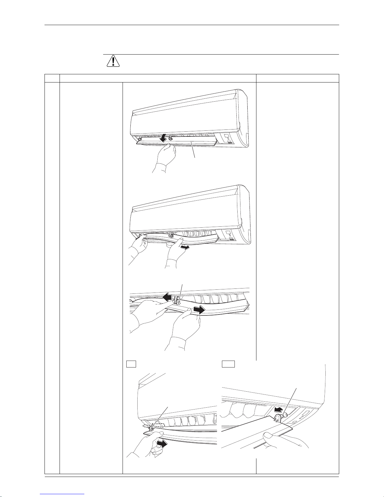
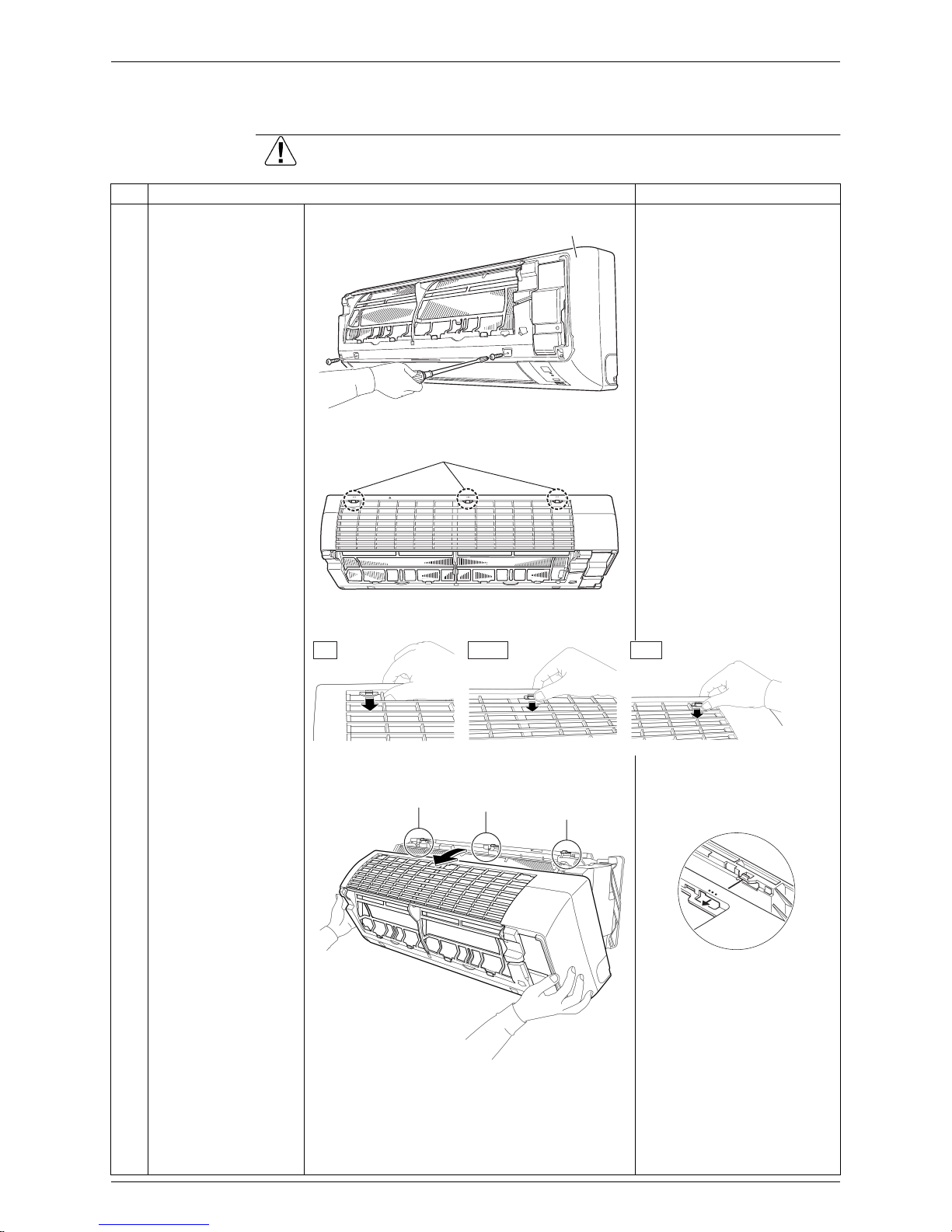
2. Remove the air filters.
The air filter is not marked
for difference between the
right and left sides.
The air filter can be set
easily by inserting it along
the guides.
Insert the air filter with the
“FRONT” mark faced up.
Be sure to insert the hooks
(at 2 lower positions) when
mounting the air filter.
1
Open the front panel to
the position where it
stops.
2
Slightly push up the
center of the air filter to
unfasten the 2 hooks.
Room temperature thermistor
(R11616)
Signal receiver
(R17276)
Operation
lamp
TIMER
lamp
[ON/OFF] button
(Forced operation [ON/OFF] button)
Front panel
(R11618)
Hook
(R14598)
Air filter

Si041139 Removal of Air Filters
Removal Procedure 3
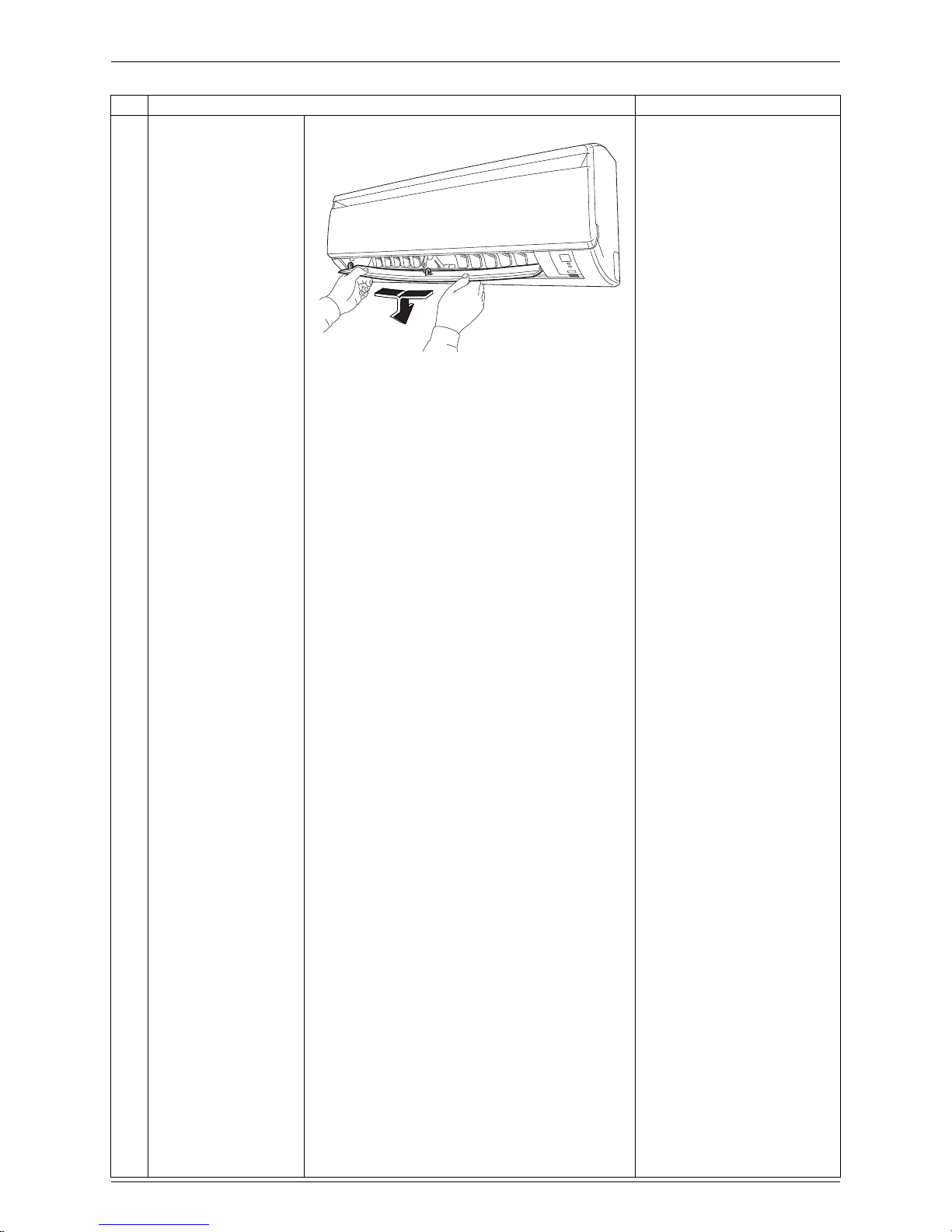
3
Pull out the air filter
downward and remove
it.
3. Remove the Titanium
apatite photocatalytic
air-purifying filters.
1
The Titanium apatite
photocatalytic airpurifying filter is
attached to the back of
the air filter.
2
Remove the Titanium
apatite photocatalytic
air-purifying filter frame
by bending the air filter
and unfastening the
projections from the air
filter frame.
3
Remove the Titanium
apatite photocatalytic
air-purifying filter from
its frame (at 5 positions)
by bending it.
To prevent the damage, do
not remove the Titanium
apatite photocatalytic airpurifying filter from the frame
when cleaning it.
The Titanium apatite
photocatalytic air-purifying
filter is not marked for
difference between the right
and left sides.
Step Procedure Points
(R11620)
Air filter
(R8025)
Titanium apatite
photocatalytic
air-purifying filter
Projection
(R14599)
Hook
(R8027)
Removal of Horizontal Blade Si041139
4 Removal Procedure
2. Removal of Horizontal Blade
Procedure Warning Be sure to wait for 10 minutes or more after turning off all power
supplies before disassembling work.
Step Procedure Points
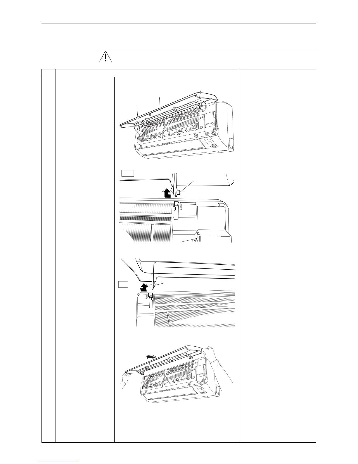
1
Open the horizontal
blade.
2
Unfasten the center
shaft while bending the
horizontal blade
slightly.
The center shaft can be
released easily by bending
the blade.
Cautions for reassembling
1. Since the key pattern hook
is provided, rotate the
horizontal blade and fit it to
the right shaft first.
2. Fit the horizontal blade to
the center and left shafts.
3
Unfasten the left shaft
of the horizontal blade.
4
Unfasten the right shaft
of the horizontal blade.
(R17293)
Horizontal blade
(R17294)
(R17331)
Shaft
(R17332)
Key pattern hook
Left
Right
Shaft
Si041139 Removal of Horizontal Blade
Removal Procedure 5
5
Remove the horizontal
blade.
Step Procedure Points
(R17333)
Removal of Front Panel Si041139
6 Removal Procedure
3. Removal of Front Panel
Procedure Warning Be sure to wait for 10 minutes or more after turning off all power
supplies before disassembling work.
Step Procedure Points
1
Open the front panel
over the position where
it stops.
2
Release the right rotary
shaft.
The rotary shaft on each
side can be released easily
by sliding each shaft inward.
3
Release the left rotary
shaft.
4
Remove the front panel.
When reassembling the
front panel, fit the right and
left rotary shafts one by one
into the grooves and fully
push them in position.
Left side
Front panel
Right side
(R11627)
Right
Rotary shaft
(R11628)
Left
Rotary shaft
(R11629)
(R11630)
Si041139 Removal of Front Grille
Removal Procedure 7
4. Removal of Front Grille
Procedure Warning Be sure to wait for 10 minutes or more after turning off all power
supplies before disassembling work.
Step Procedure Points
1
Remove the 2 screws,
which fix the front grille
to the main body.
Preparation
Remove the front panel
according to the “Removal
of Front Panel”.
2
The front grille has 3
hooks on the upper
part.
Refer to the removal
procedure in a reverse way
when reassembling.
3
Press each hook, and
also lift the grille up to
unfasten the hooks.
4
Pull the upper part of
the front grille out and
lift the lower part up,
and then remove the
front grille.
The convex marks (...) on
the front panel indicate the
position of the hooks.
When reassembling, make
sure that all the 3 hooks are
fastened as they were.
(R11631)
Front grille
(R14618)
Hook
Left Center Right
(R8030)
(R11633)
Left
Center
Right
(R12715)
Removal of Electrical Box / Vertical Blades (Pattern 1) Si041139
8 Removal Procedure
5. Removal of Electrical Box / Vertical Blades
(Pattern 1)
Procedure Warning Be sure to wait for 10 minutes or more after turning off all power
supplies before disassembling work.
Step Procedure Points
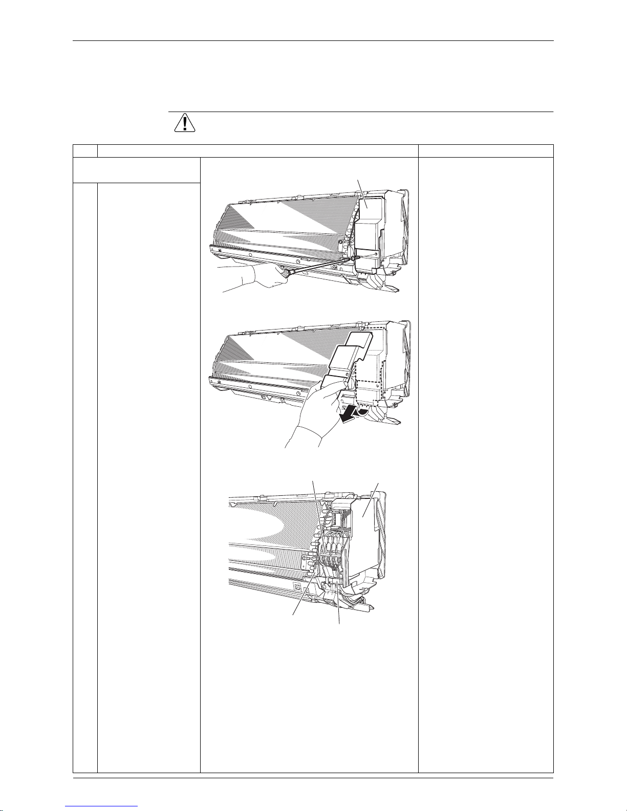
1. Disconnect the connecting
wires.
Preparation
Remove the front grille
according to the “Removal
of Front Grille”.
1
Remove the screw of
the service cover.
2
Pull out the service
cover down in the
direction of the arrow.
3
The figure shows the
connections of wire
harnesses.
(R14600)
Service cover
(R12042)
Terminal board
Electrical box
Wire retaining plate
Indoor heat exchanger thermistor
(R14586)
Si041139 Removal of Electrical Box / Vertical Blades (Pattern 1)
Removal Procedure 9
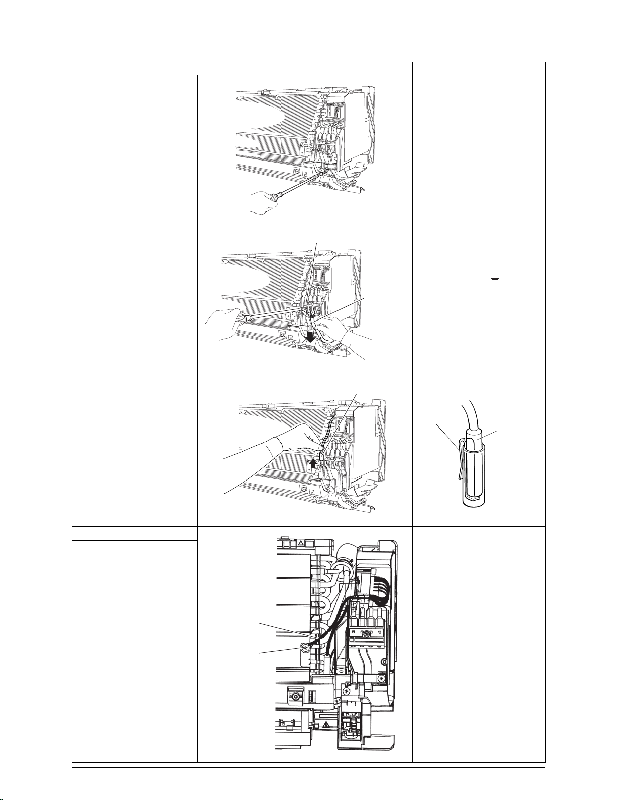
4
Remove the screw of
the wire retaining plate.
5
Remove the screws of
the terminal board and
disconnect the
connecting wires.
Connecting wires
black (1) ----- power supply
white (2) ----- power supply
red (3) ----- transmission
yellow / green ( )
----- earth / ground
6
Pull out the indoor heat
exchanger thermistor.
Take care not to lose the clip
of thermistor.
2. Remove the electrical box.
1
Remove the screw and
release the earth /
ground wire.
Step Procedure Points
(R12044)
Terminal board
(R11639)
Connecting
wires
(R12045)
Indoor heat exchanger thermistor
Clip
(R11268)
Thermistor
(R17334)
Earth / ground
wire
Screw
 Loading...