

Page 1
INSTALLATION
MANUAL
R22 SPLIT SERIES
MODELS
FHC20JEVLK RD20JEVLK
FHC25JEVLK RD25JEVLK
FHC30JEVLK RD30JEVLK
FHC40JEVLK RD40JEVLK
FHC50JEVLK RD50JETLK
FHYC20JEVLK RYD20JEVLK
FHYC25JEVLK RYD25JEVLK
FHYC30JEVLK RYD30JEVLK
Installation Manual
R22 Split Series
English
FHYC40JEVLK RYD40JEVLK
FHYC50JEVLK RYD50JETLK
IM-CKE-0911(0)-DAIKIN(SASO)
Part No.: R08019037002
Page 2

Page 3
Indoor Unit
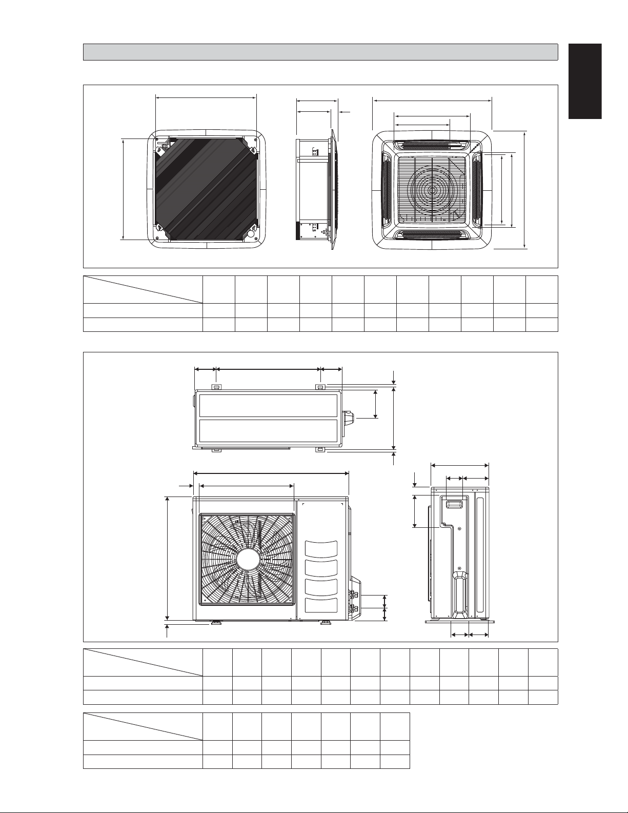
OUTLINE AND DIMENSIONS
B
C
D
E
F
H
K
English
J
A
I
G
All dimensions are in mm
Dimension
Model
ABCDE FGHI J K
FH(Y)C20/25/30JEVLK 820 820 340 300 40 990 990 627 627 607 430
FH(Y)C40/50JEVLK 820 820 375 335 40 990 990 627 627 607 430
Outdoor Unit
L
O
KL
A
D
N
All dimensions are in mm
M
QN
C
F
HG
Original Instruction
E
BP
RS
IJ
Dimension
Model
ABCDE FGHI J KL
R(Y)D20JEVLK 855 628 328 520 179 46 93 149 101 113 603 126
R(Y)D25/30JEVLK 855 730 328 520 179 46 93 149 101 113 603 126
Dimension
Model
MNO P Q R S
R(Y)D20JEVLK 164 15 34 23 362 73 75
R(Y)D25/30JEVLK 164 15 34 23 362 73 75
1-1
Page 4
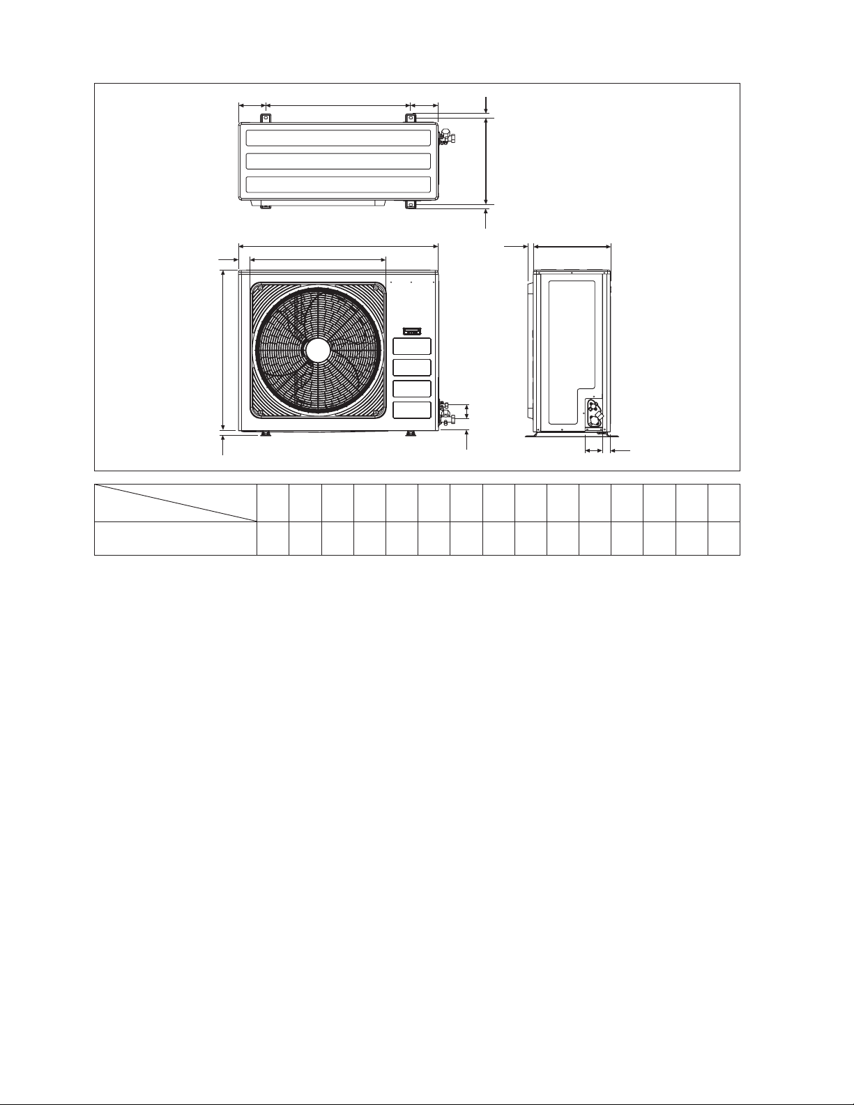
Outdoor Unit
Model
R(Y)D40JEVLK
R(Y)D50JETLK
K
B
L
Dimension
IJJ
M
NN
A
D
E
EF
O
All dimensions are in mm
C
G
H
ABCDE FGHI J KLMNO
1030 826 400 410 57 72 90 40 746 142 60 26 448 22 28
1-2
Page 5
INSTALLATION MANUAL
This manual provides the procedures of installation to ensure a safe and good standard of operation for the air
conditioner unit.
Special adjustment may be necessary to suit local requirements.
Before using your air conditioner, please read this instruction manual carefully and keep it for future reference.
This appliance is intended to be used by expert or trained users in shops, in light industry and on farms, or for
commercial use by lay persons.
This appliance is not intended for use by persons, including children, with reduced physical, sensory or mental
capabilities, or lack of experience and knowledge, unless they have been given supervision or instruction concerning
use of the appliance by a person responsible for their safety. Children should be supervised to ensure that they do
not play with the appliance.
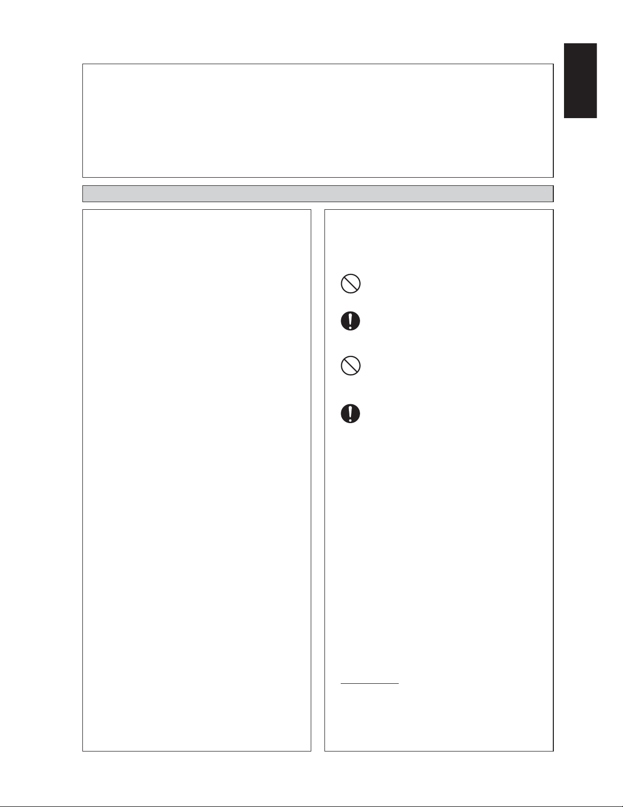
SAFETY PRECAUTIONS
! WARNING ! CAUTION
•
Installation and maintenance should be performed by
qualified persons who are familiar with local code
and regulation, and experienced with this type of
appliance.
•
All field wiring must be installed in accordance with
the national wiring regulation.
Ensure that the rated voltage of the unit corresponds to
•
that of the name plate before commencing wiring work
according to the wiring diagram.
The unit must be GROUNDED to prevent possible
•
hazard due to insulation failure.
All electrical wiring must not touch the refrigerant
•
piping, or any moving parts of the fan motors.
Confirm that the unit has been switched OFF before
•
installing or servicing the unit.
Disconnect from the main power supply before servicing
•
the air conditioner unit.
DO NOT pull out the power cord when the power is
•
ON. This may cause serious electrical shocks which
may result in fire hazards.
Keep the indoor and outdoor units, power cable and
•
transmission wiring, at least 1m from TVs and radios,
to prevent distorted pictures and static. {Depending on
the type and source of the electrical waves, static may
be heard even when more than 1m away}.
Please take note of the following important points when
installing.
•
Do not install the unit where leakage of flammable
gas may occur.
If gas leaks and accumulates around the unit, it
may cause fire ignition.
•
Ensure that the drainage piping is connected properly.
If the drainage piping is not connected properly,
it may cause water leakage which will dampen
the furniture.
•
Do not overcharge the unit.
This unit is factory pre-charged. Overcharge
will cause over-current or damage to the
compressor.
•
Ensure that the unit’s panel is closed after service
or installation.
Unsecured panels will cause the unit to operate
noisily.
•
Sharp edges and coil surfaces are potential locations
which may cause injury hazards. Avoid from being
in contact with these places.
•
Before turning off the power supply, set the remote
controller’s ON/OFF switch to the “OFF” position
to prevent the nuisance tripping of the unit. If this is
not done, the unit’s fans will start turning automatically
when power resumes, posing a hazard to service
personnel or the user.
•
Do not install the units at or near doorway.
•
Do not operate any heating apparatus too close to the
air conditioner unit or use in room where mineral oil,
oil vapour or oil steam exist, this may cause plastic
part to melt or deform as a result of excessive heat or
chemical reaction.
•
When the unit is used in kitchen, keep flour away from
going into suction of the unit.
•
This unit is not suitable for factory used where cutting oil
mist or iron powder exist or voltage fluctuates greatly.
•
Do not install the units at area like hot spring or oil
refinery plant where sulphide gas exists.
•
Ensure the color of wires of the outdoor unit and
the terminal markings are same to the indoors
respectively.
•
IMPORTANT : DO NOT INSTALL OR USE THE
AIR CONDITIONER UNIT IN A LAUNDRY
ROOM.
•
Don’t use joined and twisted wires for incoming power
supply.
•
The equipment is not intended for use in a potentially
explosive atmosphere.
English
1-3
Page 6
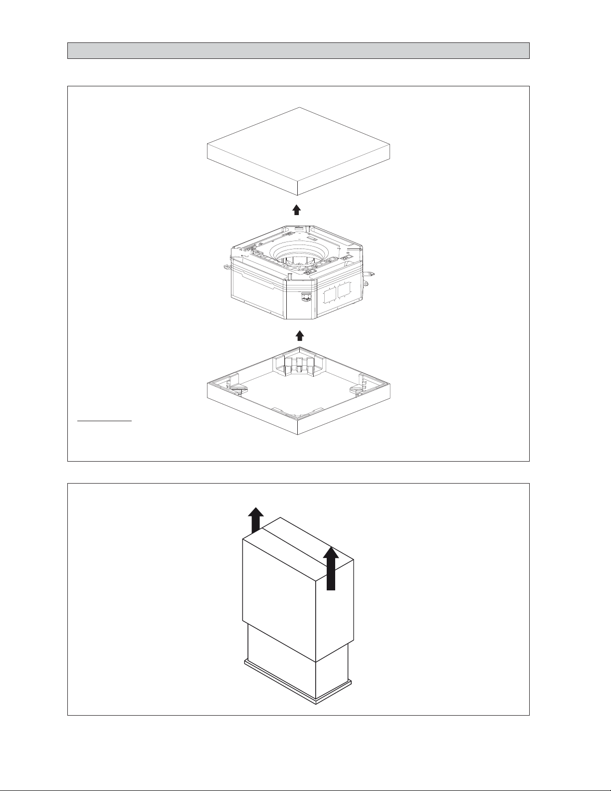
For model FH(Y)C20/25/30/40/50JEVLK:
Carton Box Top1)
IMPORTANT
Indoor Unit2)
R
BA
P
E
E
K
K UN
C
Carton Box Bottom3)
UNPACKING
After take off the bands, lift the carton box
1)
Lift the unit and remove the bottom carton.
2)
For model R(Y)D20JEVLK, R(Y)D25JEVLK, R(Y)D30JEVLK, R(Y)D40JEVLK & R(Y)D50JETLK:
1. After take off the bands, pull out the carton box from the top side of the unit.
* This product is not designed for re-packing. In case of re-packing, contact to Daikin Dealer.
1-4
Page 7
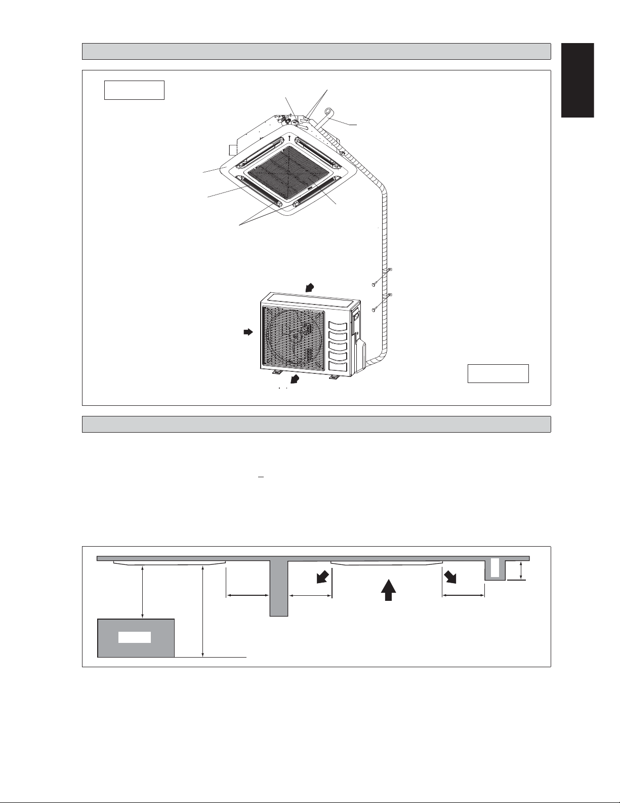
INSTALLATION DIAGRAM
Indoor Unit
Front Panel
Air Filter
(behind the grille)
Air Discharge Louver
Air Intake
Drain Piping
Air Discharge
Thermal Insulation
English
Wrap the insulated pipe with the
À nishing tape from bottom to top
Air Intake Grille
Air Intake
Outdoor Unit
INSTALLATION OF THE INDOOR UNIT
Preliminary Site Survey
Be sure to read this manual before installing the air-conditioner indoor unit.
•
Voltage supply Á uctuation must not exceed +10% of rated voltage. Electricity supply lines must be independent of
welding transformers which can cause high supply Á uctuation.
•
Ensure that the location is convenient for wiring, piping and drainage.
•
Do not exert pressure on the resin parts when opening the unit or when moving it after opening.
•
Do not move the unit from packaging while moving, until it reaches the installation site. Use safe material or protection
plates when unpacking it or lifting it to avoid damage or scratches to the unit.
Beam
1m or more
Obstacle
0.5m or more 0.5m or more 0.5m or more
3m or more
Floor
0.3m or less
1-5
Page 8
•
Ensure a location where:
a)
Drainage can be done easily.
b)
Convenient for wiring and piping.
c)
Which have enough space for installation and service work.
d)
Where no risk of Á ammable gas leakage.
e)
When free from any obstacles in path of cool air discharge and warm air return and must allow spreading of air
throughout the room (near the center of the room).
f)
Must be provided clearance for indoor unit from the wall and obstacles as shown in À gure below.
g)
The installation place must be strong enough to support a load 4 times the indoor unit weight to avoid amplifying
noise and vibration.
h)
The installation place (hanging ceiling surface) must be assuring levelness and the height in the ceiling is 350mm or
more.
i)
The indoor unit must be away from heat and steam sources (avoid installing it near an entrance).
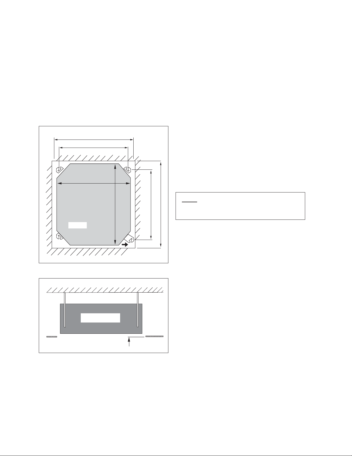
Unit Installation
Measure and mark the position for the hanging rod.
•
Ceiling Opening Site = 890mm
Hanging Rod Site = 790mm
Unit size 820mm
Drill the hole for the angle nut on the ceiling and fix the
hanging rod.
The installation template is extended according to
•
temperature and humidity. Check on dimensions in use.
The dimensions of the installation template are the same
•
as those of the ceiling opening dimensions.
Before ceiling laminating work is completed, be sure to
•
fit the installation template to the indoor unit.
Unit Hanging
Unit
Indoor Unit
Unit size 820mm
30 mm
Hanging rod size = 621mm
Ceiling Opening Site = 890mm
Piping Direction
Ceiling
Board
NOTE
Be sure to discuss the ceiling drilling work with the
installers concerned.
•
Confirm the pitch of the hanging rod is 770mm x 622mm
sharp.
•
Hold the unit and hang it on the hanging rod with the nut
and washer.
•
Adjust the unit height to 30mm between the indoor unit
bottom surface and the ceiling surface.
•
Confirm with a level gauge that the unit is installed
horizontally and tighten the nut and bolt to prevent unit
falling and vibration.
•
Open the ceiling board along the outer edge of the paper
installation template.
1-6
Page 9
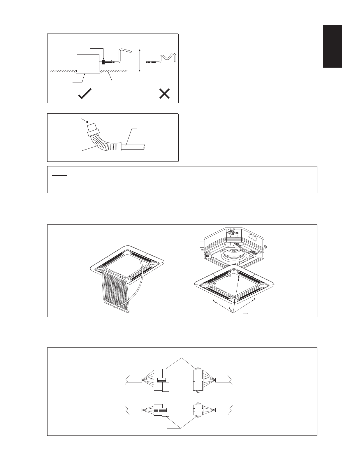
•
Drain Piping Work
Flexible Hose
Pipe Clamp
Avoid installing the drain pipe in upward gradient after
the drain connection.
•
Ensure the height of drain pipe from ceiling is 700mm or
less if it is necessary to increase the height of drain pipe
to prevent water leak.
Avoid installing the drain pipe in up and down slope to
•
prevent reversed water flow.
•
During the drain pipe connection, be careful not to exert
extra force on the drain connector at indoor unit.
•
The outside diameter of the drain connection at the
Panel
Indoor
Unit
700.0mm or less
Ceiling
flexible drain hose is 20mm.
•
Be sure to execute heat insulation (polyethylene foam
with thickness more than 8mm) on the drain piping to
Drain Test
Feed Water
Main Drain Pipe
avoid the condensed water dripping inside the room.
•
Connect the main drain pipe to the flexible drain hose.
•
Feed water from flexible drain hose to check the piping
for leakage.
•
Flexible Drain Hose
When the test is completed, connect the flexible drain
hose to the drain connector on the indoor unit.
NOTE
This Indoor Unit uses a drain pump for condensed water drainage. Install the unit horizontally to prevent water leakage
or condensation around the air outlet.
English
Panel Installation
The front panel can only be fitted in one direction, follow the piping direction. (Follow piping arrow sticker on front
•
panel)
Be sure to remove the installation template before installing the front panel.
•
Open
Screw
•
Open the air intake grille by pulling back the catchers and removing it together with filter from panel.
•
Install the front frame panel onto the indoor unit by 4 screws and tighten it completely to prevent cool air leakage.
•
Connect the LED wire and air swing wire to the indoor unit.
•
The air swing connector must put inside the control box after connected.
LED Wire
From
Front
Panel
From
Unit
Control
Box
Air Swing Wire
1-7
Page 10
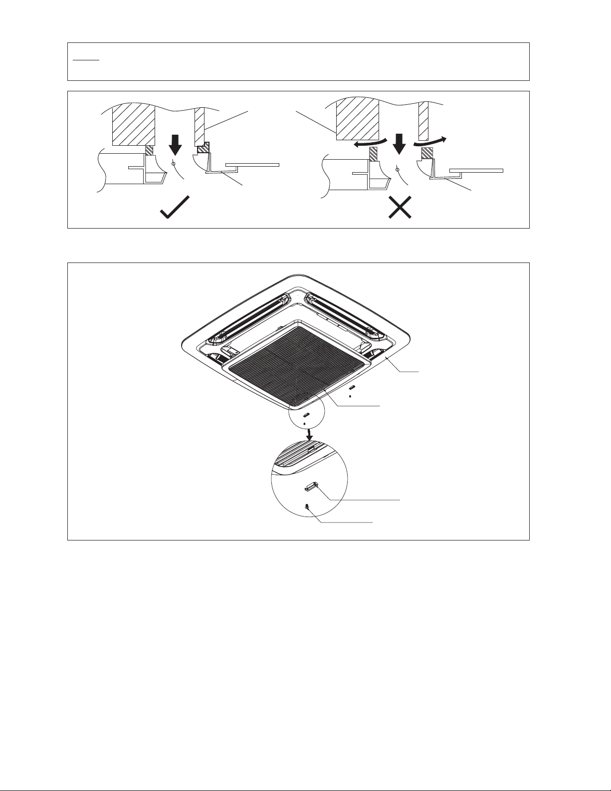
NOTE
Install the front frame panel À rmly to prevent cool air leakage which will cause condensation and water dripping.
Indoor Unit
Cool
Air
Air Leak
Ceiling Board
Panel
Grille Lock Cover (The moving part protection for user direct touching)
Grille lock cover must be installed as the À gure below.
Cool
Air
Frame
Air Leak
Ceiling Board
Panel
Intake Grille
Grille Lock Cover
(2pcs)
Screw 4 x 6
(2pcs)
If the unit need to be service, steps below shall be followed:
1.
ConÀ rm that the unit had been switched off before servicing the unit.
2.
Use screwdriver to unlock the screw on the grille lock cover.
3.
Remove the grille lock cover and open the intake grille for the service purpose.
4.
Install the intake grille and screw the grille lock cover after service and make sure the unit is proper install.
1-8
Page 11

Wires Installation
Figure A
Figure A and Figure B shows the location of cover wire in FH(Y)C unit.
Steps to install power supply wires and wires from outdoor unit.
Remove wire cover by removing 2 screws as shown in Figure C.
1.
Wires will go through the hole as shown in Figure D and E respectively without crossing the height of the hole.
2.
After that, wire cover will be assembled back to close the wire.
3.
English
Figure B Figure C
Figure D Figure E
1-9
Page 12

INSTALLATION OF THE OUTDOOR UNIT
As condensing temperature rises, evaporating temperature rises and cooling capacity drops. In order to achieve maximum
cooling capacity, the location selected for outdoor unit should fulfill the following requirements:
Install the condensing (outdoor) unit in a way such that the hot air distributed by the outdoor condensing unit cannot be drawn
•
in again (as in the case of short circuit of hot discharge air). Allow sufficient space for maintenance around the unit.
Ensure that there is no obstruction of air Á ow into or out of the unit. Remove obstacles which block air intake or
•
discharge.
The location must be well ventilated, so that the unit can draw in and distribute plenty of air thus lowering the condensing
•
temperature.
A place capable of bearing the weight of the outdoor unit and isolating noise and vibration.
•
A place protected from the direct sunlight. Otherwise use an awning for protection, if necessary.
•
The location must not be susceptible to dust or oil mist.•
! CAUTION
Do not install the unit at altitude over 2000m for both indoor and outdoor.•
1-10
Page 13

INSTALLATION CLEARANCE
Outdoor units must be installed such that there is no short circuit of the hot discharge air or obstruction to smooth air Á ow.
•
Select the coolest possible place where intake air should not be hotter than the outside temperature (refer to operating
range).
English
AB
Air
Inlet
Obstacle
All Model
Minimum Distance (mm)
Air
Discharge
Obstacle
ABCD
300 1000 300 500
Condensed Water Disposal Of Outdoor Unit
(Heat Pump Unit Only)
There are 2 holes on the base of Outdoor Unit for condensed
•
water to Á ow out. Insert the drain elbow to one of the
holes.
To install the drain elbow, À rst insert one portion of the
•
hook to the base (portion A), then pull the drain elbow in
the direction shown by the arrow while inserting the other
portion to the base. After installation, check to ensure that
the drain elbow clings to base À rmly.
If the unit is installed in a snowy and chilly area, condensed
•
water may freeze in the base. In such case, please remove
plug at the bottom of unit to smooth the drainage.
BASE
C
Obstacle
A
PLUG
DRAIN ELBOW
DRAIN ELBOW
D
Service
Space
Please remove side
plate when connecting
the piping and
connecting cord
Not applicable to
R(Y)D40JEVLK & R(Y)D50JETLK
Obstacle
PUSH & PULL UP
REFRIGERANT PIPING
Maximum Allowable Pipe Length and Elevation
If the piping is too long, both the capacity and reliability of unit will drop. As the number of bends increase, resistance to
Á ow of refrigerant system increases, thus lowering cooling capacity and as a result the compressor may become defective.
Always choose the shortest path and follow the recommendation as tabulated below.
Model
Indoor
Outdoor
Max. allowable length, m
Max. allowable elevation, m
Liquid pipe size, mm/(in)
Gas pipe size, mm/(in)
NOTE
Be sure to add the proper amount of additional refrigerant, failure to do so may result in reduced performance.
Remark: The refrigerant pre-charged in the outdoor unit is for the piping length up to 7.5m.
FH(Y)C20JEVLK FH(Y)C25JEVLK FH(Y)C30JEVLK FH(Y)C40JEVLK FH(Y)C50JEVLK
R(Y)D20JEVLK R(Y)D25JEVLK R(Y)D30JEVLK R(Y)D40JEVLK R(Y)D50JETLK
30 30 40 40 45
15 15 25 25 25
6.35(1/4") 9.52(3/8") 9.52(3/8") 9.52(3/8") 9.52(3/8")
15.88(5/8") 15.88(5/8") 15.88(5/8") 19.05(3/4") 19.05(3/4")
1-11
Page 14

Piping Works And Flaring Technique
Do not use contaminated or damaged copper tubing. If any pipings, evaporator or condenser had been exposed or had been
•
opened for 15 seconds or more, the system must be vacuumed. Generally, do not remove plastic, rubber plugs and brass
nuts from the valves, fittings, tubings and coils until it is ready to connect suction or liquid line into valves or fittings.
If any brazing work is required, ensure that the nitrogen gas is passed through coil and joints while the brazing work is
•
being done. This will eliminate soot formation on the inside walls of the copper tubings.
Cut the pipe stage by stage, advancing the blade of the pipe cutter slowly. Extra force and deep cut will cause more distortion
•
on the pipe and thus extra burr. See Figure I.
Remove burrs from cut edges of the pipes with remover
•
as shown in Figure II. This will avoid unevenness on the
flare faces which will cause gas leak. Hold the pipe on
top position and burr remover at lower position to prevent
metal chips from entering the pipe.
Insert the flare nuts, mounted on the connection parts
•
of both the indoor unit and outdoor unit, into the copper
pipes.
The exact length of pipe protruding from the top surface
•
of the swaging block is determined by the flaring tool.
Refer Figure III.
Fix the pipe firmly on the flare die. Match the centers of
•
both the flare die and the flaring punch, and then tighten
the flaring punch fully.
Piping Connection To The Units
Align the center of the piping and tighten the flare nut
•
sufficiently with fingers. Refer Figure IV.
Finally, tighten the flare nut with the torque wrench until
•
the wrench clicks.
When tightening the flare nut with the torque wrench,
•
ensure that the tightening direction follows the arrow
indicated on the wrench.
The refrigerant pipe connection are insulated by closed
•
cell polyurethane.
Figure I
1/4t
Figure II
Figure III
Swaging Block
Cutting Copper Tube
Remove Burr
Copper Tube
D
A
Pipe Size (mm/in) Torque (Nm/ft-lb)
6.35 (1/4") 18 (13.3)
9.52 (3/8") 42 (31.0)
12.70 (1/2") 55 (40.6)
15.88 (5/8") 65 (48.0)
19.05 (3/4") 78 (57.6)
Ø Tube, D A (mm)
Inch mm
Imperial
(Wing-nut Type)
1/4" 6.35 1.3 0.7
3/8" 9.52 1.6 1.0
1/2" 12.70 1.9 1.3
5/8" 15.88 2.2 1.7
3/4" 19.05 2.5 2.0
Rigid
(Clutch Type)
1-12
Figure IV
Flare Joint
Indoor Piping
Spanar
Flared Tube
Flare Nut
Torque Wrench
Page 15

ELECTRICAL WIRING CONNECTION
IMPORTANT :
* These values are for information only. They should be checked and selected to comply with local and/or
national codes and regulations. They are also subject to the type of installation and size of conductors.
** The appropriate voltage range should be checked with data label on the unit.
FHC20JEVLK - RD20JEVLK
FHC25JEVLK - RD25JEVLK
COMP
L1
N1
L
N
Outdoor Unit
Terminal Block
There must be an all pole
disconnection in the supply
mains with a contact separation
of at least 3mm.
Indoor Unit
Terminal Block
COMP
Interconnection Cable
L
N
Power Supply
Cable
Model Indoor FHC20JEVLK FHC25JEVLK
Outdoor RD20JEVLK RD25JEVLK
Voltage range** Indoor
Outdoor
Power supply cable size* mm
Number of conductors
Interconnection cable size* mm
Number of conductors
2
2
220V/1Ph/60Hz +
220V/1Ph/60Hz +
2.5
3
1.0
4
!
!
2.5
3
1.0
4
Recommended time delay fuse* A 20 25
English
FHC30JEVLK - RD30JEVLK
COMP
Indoor Unit
Terminal Block
Interconnection Cable
L
N
COMP
L
N
Outdoor Unit
Terminal Block
L
Power Supply Cable
N
There must be an all pole
disconnection in the supply
mains with a contact separation
of at least 3mm.
Model Indoor FHC30JEVLK
Outdoor RD30JEVLK
Voltage range** Indoor
Outdoor
Power supply cable size* mm
Number of conductors
Interconnection cable size* mm
Number of conductors
2
2
220V/1Ph/60Hz +
220V/1Ph/60Hz +
4.0
3
2.5
4
Recommended time delay fuse* A 30
!
!
1-13
Page 16

FHC40JEVLK - RD40JEVLK
COMP
L
Outdoor Unit
Terminal Block
N
L
N
There must be an all pole
disconnection in the supply
mains with a contact separation
of at least 3mm.
Indoor Unit
Terminal Block
COMP
Interconnection Cable
L
N
Power Supply Cable
Model Indoor FHC40JEVLK
Outdoor RD40JEVLK
Voltage range** Indoor
Outdoor
Power supply cable size* mm
Number of conductors
Interconnection cable size* mm
Number of conductors
2
2
220V/1Ph/60Hz +
220V/1Ph/60Hz +
6.0
3
2.5
4
Recommended time delay fuse* A 35
!
!
FHC50JEVLK - RD50JETLK
COMP
Indoor Unit
Terminal Block
Interconnection Cable
L
N
COMP
L
N
Outdoor Unit
Terminal Block
R
S
Power Supply Cable
T
There must be an all pole
disconnection in the supply
mains with a contact separation
of at least 3mm.
Model Indoor FHC50JEVLK
Outdoor RD50JETLK
Voltage range** Indoor
Outdoor
Power supply cable size* mm
Number of conductors
Interconnection cable size* mm
Number of conductors
2
2
220V/1Ph/60Hz +
220V/3N~/60Hz +
6.0
3
2.5
4
Recommended time delay fuse* A 35
!
!
1-14
Page 17

FHYC20JEVLK - RYD20JEVLK
FHYC25JEVLK - RYD25JEVLK
Outdoor Coil Sensor
4WV
OF
COMP
Outdoor Unit
L1
Terminal Block
N1
L
Indoor Unit
Terminal Block
4WV
OF
COMP
L
N
Interconnection Cable
Power Supply
Cable
N
There must be an all pole
disconnection in the supply
mains with a contact separation
of at least 3mm.
Model Indoor FHYC20JEVLK FHYC25JEVLK
Outdoor RYD20JEVLK RYD25JEVLK
Voltage range** Indoor
Outdoor
Power supply cable size* mm
Number of conductors
Interconnection cable size* mm
Number of conductors
2
2
220V/1Ph/60Hz +
220V/1Ph/60Hz +
2.5
3
1.0
6
!
!
2.5
3
1.0
6
Recommended time delay fuse* A 20 25
English
FHYC30JEVLK - RYD30JEVLK
Outdoor Coil Sensor
Indoor Unit
Terminal Block
4WV
OF
COMP
L
N
Interconnection Cable
Power Supply Cable
4WV
OF
Outdoor Unit
COMP
Terminal Block
L
N
L
N
There must be an all pole
disconnection in the supply
mains with a contact separation
of at least 3mm.
Model Indoor FHYC30JEVLK
Outdoor RYD30JEVLK
Voltage range** Indoor
Outdoor
Power supply cable size* mm
Number of conductors
Interconnection cable size* mm
Number of conductors
2
2
220V/1Ph/60Hz +
220V/1Ph/60Hz +
4.0
3
2.5
3 & 3
Recommended time delay fuse* A 30
!
!
1-15
Page 18

FHYC40JEVLK - RYD40JEVLK
Outdoor Coil Sensor
A
4WV
OF
Outdoor Unit
Terminal Block
COMP
L
N
L
N
There must be an all pole
disconnection in the supply
mains with a contact separation
of at least 3mm.
Indoor Unit
Terminal Block
A
4WV
OF
COMP
L
N
Interconnection Cable
Power Supply Cable
Model Indoor FHYC40JEVLK
Outdoor RYD40JEVLK
Voltage range** Indoor
Outdoor
Power supply cable size* mm
Number of conductors
Interconnection cable size* mm
Number of conductors
2
2
220V/1Ph/60Hz +
220V/1Ph/60Hz +
6.0
3
2.5
4 & 3
Recommended time delay fuse* A 35
!
!
FHYC50JEVLK - RYD50JETLK
Outdoor Coil Sensor
A
4WV
Outdoor Unit
Terminal Block
OF
COMP
L
N
R
Indoor Unit
Terminal Block
A
4WV
OF
COMP
L
N
Interconnection Cable
Power Supply Cable
S
T
There must be an all pole
disconnection in the supply
mains with a contact separation
of at least 3mm.
Model Indoor FHYC50JEVLK
Outdoor RYD50JETLK
Voltage range** Indoor
Outdoor
Power supply cable size* mm
Number of conductors
Interconnection cable size* mm
Number of conductors
2
2
220V/1Ph/60Hz +
220V/3N~/60Hz +
6.0
3
2.5
4 & 3
Recommended time delay fuse* A 35
!
!
1-16
Page 19

All wires must be firmly connected.
•
Make sure all the wire do not touch the refrigerant pipings, compressor or any moving parts.
•
The connecting wire between the indoor unit and the outdoor unit must be clamped on the wire clamps.
•
The power supply cord must be equivalent to H07RN-F which is the minimum requirement.
•
Make sure no external pressure is applied to the terminal connectors and wires.
•
Make sure all the covers are properly fixed to avoid any gap.
•
Use round crimp-style terminal for connecting wires to the power supply terminal block. Connect the wires by matching
•
to the indication on terminal block. (Refer to the wiring diagram attached on the unit).
Attach insulation sleeve
Electric wire
Round crimp-style terminal
Use the correct screwdriver for terminal screws tightening. Unsuitable screwdrivers can damage the screw head.
•
Over tightening can damage the terminal screw.
•
Do not connect wire of different gauge to same terminal.
•
Keep wiring in an orderly manner. Prevent the wiring from obstructing other parts and the terminal box cover.
•
English
Connect wires of the
same gauge to both side.
Do not connect wires of the
same gauge to one side.
Do not connect wires
of different gauges.
1-17
Page 20

VACUUMING AND CHARGING
Vacuuming is necessary to eliminate all moisture and air from the system. The series II Outdoor Unit is provided with flare
valve fittings.
Vacuuming The Piping And The Indoor Unit
Except for the outdoor unit which is pre-charged with refrigerant,
Allen key
Flare nut
Refrigerant Piping
the indoor unit and the refrigerant connection pipes must be airpurged because the air containing moisture that remains in the
refrigerant cycle may cause malfunction of the compressor.
Remove the caps from the valve and the service port.
•
Connect the center of the charging gauge to the vacuum
•
pump.
Connect the charging gauge to the service port of the 3-way
•
Service Port
Outdoor Unit 3 Ways Valve
valve.
Start the vacuum pump. Evacuate for approximately 30
•
minutes. The evacuation time varies with different vacuum
pump capacity. Confirm that the charging gauge needle has
moved towards -760mmHg.
Caution
If the gauge needle does not move to -760mmHg, be sure to
•
check for gas leaks (using the refrigerant detector) at flare type
connection of the indoor and outdoor unit and repair the leak
before proceeding to the next step.
Close the valve of the changing gauge and stop the vacuum
•
pump.
On the outdoor unit, open the suction valve (3 way) and liquid
•
valve (2 way) (in anti-clockwise direction) with 4mm key for
LOW PRESSURE GAUGE
-760mmHg
HANDLE LO
CHARGE HOSE
LIQUID VALVE
GAS VALVE
(3-WAY)
HIGH PRESSURE GAUGE
GAUGE MANIFOLD
HANDLE HI (ALWAYS CLOSED)
CHARGE HOSE
CONFIGURATION OF AIR
PURGE BY CHARGING
VACUUM PUMP
ADAPTER FOR
COUNTER FLOW
PREVENTION
CHECK VALVE
hexagon sacked screw.
Charge Operation
This operation must be done by using a gas cylinder and a precise
weighing machine. The additional charge is topped-up into the
outdoor unit using the suction valve via the service port.
•
Remove the service port cap.
•
Connect the low pressure side of the charging gauge to the
suction service port center of the cylinder tank and close the
high pressure side of the gauge. Purge the air from the service
hose.
•
Start the air conditioner unit.
•
Open the gas cylinder and low pressure charging valve.
•
When the required refrigerant quantity is pumped into the unit,
close the low pressure side and the gas cylinder valve.
•
Disconnect the service hose from service port. Put back the
service port cap.
LOW PRESSURE GAUGE
-760mmHg
HANDLE LO
CHARGE HOSE
LIQUID VALVE
GAS VALVE
(3-WAY)
HIGH PRESSURE GAUGE
GAUGE MANIFOLD
HANDLE HI (ALWAYS CLOSED)
CHARGE HOSE
CHECK VALVE
CONFIGURATION OF AIR
PURGE BY CHARGING
1-18
Page 21

ADDITIONAL CHARGE
The refrigerant is pre-charge in the outdoor unit. If the piping length is less than 7.5m, then additional charge after
vacuuming is not necessary. If the piping length is more than 7.5m then use the additional charge value as indicated in the
table.
Additional refrigerant charge [g] per additional 1m length as tabulated (for R22 models)
Cooling only
Model
Additional charge [g/m] 22 55
Indoor FHC20JEVLK FHC25JEVLK
Outdoor RD20JEVLK RD25JEVLK*
English
Model
Additional charge [g/m] 57 40
Model
Additional charge [g/m] 58
Heat Pump Unit
Model
Additional charge [g/m] 22 55
Model
Additional charge [g/m] 57 40
Model
Additional charge [g/m] 58
Example:
FHC20JEVLK & RD20JEVLK with 13m piping length, additional piping length is 5.5m. Thus,
Additional charge = 5.5[m] x 22[g/m]
= 121[g]
Indoor FHC30JEVLK FHC40JEVLK
Outdoor RD30JEVLK RD40JEVLK
Indoor FHC50JEVLK
Outdoor RD50JETLK
Indoor FHYC20JEVLK FHYC25JEVLK
Outdoor RYD20JEVLK RYD25JEVLK*
Indoor FHYC30JEVLK FHYC40JEVLK
Outdoor RYD30JEVLK RYD40JEVLK
Indoor FHYC50JEVLK
Outdoor RYD50JETLK
! CAUTION
* When connect with FHC25JEVLK and FHYC25JEVLK, additional 0.2kg refrigerant charge is needed for 3.0m to
7.5m piping length.
1-19
Page 22

SPECIAL PRECAUTIONS WHEN CHARGING UNIT WITH SCROLL COMPRESSORS
These precautions are intended for use with Scroll compressors only with R22 refrigerants but are not applied to others
competitive Scroll compressors.
Scroll compressors have a very high volumetric efficiency and quickly pump a deep vacuum if there is insufficient refrigerant
in the system or if refrigerant is added too slowly. Operation with low suction pressure will quickly lead to very high discharge
temperatures. While this process is happening, the scrolls are not being well lubricated – scrolls depend on the oil mist in the
refrigerant for lubrication. A lack of lubrication leads to high friction between the scroll flanks and tips and generates additional
heat. The combination of heat of compression and heat from increased friction is concentrated in a small localized discharge
area where temperatures can quickly rise to more than 300ÝC. These extreme temperatures damage the Scroll spirals and the
orbiting Scroll bearing. This damage can occur in less than one minute especially on larger compressors. Failure may occur
in the first few hours or the damage done during field charging may show up some time later.
Other typical field charging problems include undercharging, overcharging, moisture or air in the system etc. In time each
one of these problems can cause compressor failure.
Minimal equipment is required for field charging. The minimum equipment required to do a satisfactory job is:-
Set of service gauges1. Vacuum gauge4.
Hoses2. Scales5.
Vacuum pump3. Thermometer
The proper refrigerant charge should follow the volume as recommended by manufacturer and recommendation should be
followed by the installer.
Charging procedures – Single phase compressors
1.
Evacuate the system to -760mmHg. To reduce evacuation time, use short, large diameter hoses and connect to unrestricted
service ports on the system. Quality of vacuum cannot be determined by time – a reliable vacuum gauge must be used.
(etc. electronic vacuum gauge)
Turn the refrigerant cylinder upside down, purge the charging hose and charge liquid through the liquid line charging port
until refrigerant no longer flows or until the correct charge has been weighed in. If additional charge is required start the
system and slowly bleed liquid into the suction side until the system is full.
It recommends charging liquid in a CONTROLLED manner into the suction side until the system is full.
This recommendation does not hold true for reciprocating compressors where liquid charging into the suction side could
cause severe damage.
Carefully monitor the suction and discharge pressures – ensure that the suction pressure does not fall below 25 psig (1.7 bar)
at any time during the charging process.
6.
Dip-pipe
Invert cylinder
without dip-pipe
Liquid withdrawal
! CAUTION
Manifold Gauge will show cylinder pressure rather than suction pressure if the cylinder valve and Manifold
•
valve “A” are both open.
1-20
Page 23

There are many ways of charging liquid in a “controlled manner” into the
suction side:-
1.
Use valve A on the manifold gauge set
2.
Use the valve on the refrigerant cylinder
3.
Charge through a Shredder valve
4.
Use a hose with a Shredder valve depressor
5.
A
2.
Charging procedures – Three phase compressors
Charge into the suction side at some distance from the compressor
6.
All of the above
The fundamental procedure is the same as for single phase models but the compressor can run in the wrong direction on
starting.
If this happens reverse any two phases and start again. Short term reverse rotation will not damage the compressor.
All Specter compressors have internal discharge temperature protectors which are very effective in preventing dangerously
high discharge temperatures during charging. The protection module will trip and lock the compressor out for 30 minutes.
It is not normally necessary to wait 30 minutes for the module to reset. When the compressor has cooled down the module
can be reset by breaking the power supply to the control circuit. Very often the serviceman does not understand why the
module tripped and uses a jumper wire to bypass it. He continues to charge the system and removes the jumper when
charging is complete. The compressor may or may not run with the protector back in the circuit but it is certain that the
compressor has been damaged and premature failure is inevitable.
OPTIONAL FUNCTIONS
Short Duct SpeciÀ cation
•
The indoor unit is provided with air discharge and air intake “knock-out” hole for duct connection. However the connection
of the short duct for air discharge is possible on only one side.
The use of short duct for air discharge will improve airflow distribution if there is an obstruction (such as a lighting fixture)
•
or in a long, narrow room or an L-shaped room. It also use for air conditioning of two rooms simultaneously.
Possible Direction For Air Discharge And Air Intake
Possible Opening Dimension For Duct Connection
English
Air DischargeAir Discharge
PCD Ø140
Ø100
Air Intake Knock
Out Hole
Air Discharge Air Discharge
Air Intake
50 50 50 50 50 10
10
90
115 2 0 11 5
Air Discharge Knock Out Hole
207020
NOTE
Avoid using the short duct on which the air discharge grille can be completely closed, to prevent evaporator
•
freezing.
In order to prevent condensation forming, be sure that there is sufficient thermal insulation and no leakage of cool air
•
when installing the short duct.
Keep the introduction of fresh air intake within 20% of total air Á ow. Also provide a chamber and use a booster fan.
•
Sealing Material
It is possible to seal one of the four air discharge outlet. (sealing two or more air discharge outlet could cause a
•
malfunction)
Remove the front panel and insert the sealing material into the air discharge outlet on the indoor unit to seal the air
•
outlet.
•
The sealing material is the same length as the longer air discharge outlet. If it is desired to seal the shorter air discharge
outlet, cut the sealing material to shorten it.
Push the sealing material in about 10mm beyond the bottom surface of the indoor unit so that it does not touch the air
•
louver. Be sure not to push the sealing material in any farther than about 10mm.
1-21
Page 24

INDICATOR LIGHTS
FAULT DIAGNOSIS
Wireless Controller
When there is infrared remote control operating signal, the signal receiver on indoor unit will make a <beep> for signal
acceptance conÀ rmation.
Wired Controller
If there is any abnormal condition detected, wired controller will blink the error code.
Event Power LED Timer LED Other LEDs Error Code
1. Room Sensor Open or Short Blink 1 time - Blink Fan Blink E1
2. Indoor Coil Sensor Open Blink 2 times - Blink Sleep Blink E2
3. Outdoor Coil Sensor Open Blink 3 times - Blink Dry Blink E3
4. Compressor Overload /
Indoor Coil Sensor Short /
Outdoor Coil Sensor Short
5. Low Refrigerant Charge/Gas Leak/Outdoor
Abnormal
6. Water Pump Fault - Blink 2 times Blink Cool & Fan Blink E6
7. Outdoor Coil Sensor Exist (MS model) - Blink 5 times Blink Cool & Heat Blink E7
8. Hardware Error (tact switch pin short) - Blink 6 times Blink Heat, Cool,
- Blink 1 time Blink Cool Blink E4
- Blink 3 times Blink Cool & Dry Blink E5
Blink E8
follow by Fan, Dry
NOTE
Power LED = Cool/Dry/Fan LED, turns on in these modes
The unit will not detect sensor missing when the compressor is ON
Call your dealer immediately when this error happen
OPERATING RANGE
COOLING HEATING
Outdoor
DB (°C)
54
52
19
Outdoor
WB (°C)
18
10
-9
14 19 23
Indoor WB (°C)
1-22
15
20 27
Indoor DB (°C)
DB = Dry Bulb WB = Wet Bulb
Page 25

OVERALL CHECKING
Ensure that:
•
The unit has been mounted solidly and rigid in
1)
position.
The piping and connections are leak-proof after the
2)
charging.
3)
Proper wiring has been installed.
•
Drainage check
– pour some water into the left side of the drain pan (the
drainage is at the right side of the unit).
•
Test run:
1)
Conduct a test run on the unit after having perform
the water drainage test and the gas leakage test.
2)
Check the following items:
a)
Is the electrical plug inserted firmly into the socket?
•
Is
b)
there any abnormal sounds from the unit?
c)
Is there any abnormal vibrations on the unit or the
piping?
he drainage of water smooth?
d)
Is t
Confirm that:
The condenser fan is running. Check the warm air
1)
blowing from the condensing unit.
The evaporator blower is running and discharge cool
2)
air.
The suction (low side) pressure is as recommended.
3)
The remote controller incorporates a 3-minute
4)
delay protection in the circuit, whereby the outdoor
condensing unit requires about 3 minutes delay before
it can start operating.
PHASE PROTECTOR (OPTIONAL)
The unit with Scroll Compressor can only rotate in one direction. For this reason, a protective device (phase protector) is fitted
to prevent incorrect wiring of the electrical phases. When the three phases are not connected correctly, the phase protector
operates, and the unit will not start. This device is located in the control box of the outdoor unit.
The following table shows the LED indicator light for phase protector under normal operation and fault conditions.
English
Description
Normal operation
Reverse phase
T phase missing
S phase missing
R phase missing
S &T phase missing
Overload
+
Sensor missing
ON
LED
+
PW
(Red)
P_R
(Yellow)
P_S
(Yellow)
P_T
(Yellow)
Actions
-
Switch off the unit. Check the 3 phase wiring.
Switch off the unit. Check the 3 phase wiring.
Switch off the unit. Check the 3 phase wiring.
Switch off the unit. Check the 3 phase wiring.
+
Switch off the unit. Check the 3 phase wiring.
High discharge temperature. Check the refrigerant system.
Switch off the unit. Plug in sensor.
OFF
Fast Blink
NOTE
1. “+” indicates additional functions for PP01 phase protector.
2. When R phase missing, no LED or buzzer will indicate the error, but relay 71 and relay 81 will cut off.
SERVICE AND MAINTENANCE
Service Parts Maintenance Procedures Period
Indoor Air Filter Remove any dust adhering to the À lter by using a vacuum cleaner
1.
or wash in lukewarm water (below 40°C) with a neutral cleaning
detergent.
Rinse the À lter well and dry before placing it back onto the unit.
2.
Do not use gasoline, volatile substances or chemicals to clean the À lter.
3.
At least every
2 week.
More frequently
if necessary.
Indoor Unit Clean any dirt or dust on the grille or panel by wiping it with a soft
1.
cloth soaked in lukewarm water (below 40°C) and a neutral detergent
solution.
Do not use gasoline, volatile substances or chemicals to clean the indoor
2.
unit.
At least every
2 week.
More frequently
if necessary.
Indoor Fan Check for any abnormal noise.1. When necessary
! CAUTION
Avoid direct contact of any coil treatment cleaners on plastic part. This may cause plastic part to deform
•
as a result of chemical reaction.
1-23
Page 26

TROUBLESHOOTING
For any enquiries on spare parts, please contact your authorized dealer. If any malfunction of the air
conditioner unit is noted, immediately switch off the power supply to the unit. Check the following fault
conditions and causes for some simple troubleshooting tips.
Fault Causes / Action
The compressor does not start operate after 3 minutes
1. Protection against frequent starting. Wait for 3 to 4
from starting the air conditioner unit.
–
minutes for the compressor to start operating.
The air conditioner unit does not operate.2. Power failure, or the fuse need to be replaced.
The air flow is too low.3. The air filter is dirty.
Discharge air flow has bad odor.4. Odors may be caused by cigarettes, smoke particles,
Condensation on the front air grille of the indoor unit.5. This is caused by air humidity after an extended long
Water flowing out from the air conditioner unit.6. Switch off unit and call local dealer/serviceman.–
–
The power plug is disconnected.
–
It is possible that your delay timer has been set
–
incorrectly.
–
The air suction and discharge are clogged.
–
The regulated temperature is not high enough (applicable
–
for auto fan mode only).
–
perfume etc. which might have adhered onto the coil.
–
period of operation.
The set temperature is too low, increase the temperature
–
setting and operate the unit at high fan speed.
If the fault persists, please call your local dealer / serviceman.
1-24
Page 27

SPECIFICATIONS
MODEL INDOOR UNIT FHC20JEVLK FHC25JEVLK
OUTDOOR UNIT RD20JEVLK RD25JEVLK
RATED VOLTAGE V 220 220
RATED FREQUENCY Hz 60 60
COOLING (T1)
INDOOR
27DBºC/19WBºC
OUTDOOR
35DBºC/24WBºC
COOLING (T3)
INDOOR
29DBºC/19WBºC
OUTDOOR
46DBºC/24WBºC
NET WEIGHT INDOOR UNIT
REFRIGERANT R22
COUNTRY OF ORIGIN INDOOR UNIT
RATED CURRENT A 9.41 11.8
RATED POWER INPUT kW 2.06 2.59
CAPACITY Btu/h 19500 23300
kW 5.72 6.83
EER (Btu/h)/W 9.46 9.00
RATED CURRENT A 10.7 13.4
RATED POWER INPUT kW 2.33 2.96
CAPACITY Btu/h 17100 21600
kW 5.01 6.33
EER (Btu/h)/W 7.33 7.29
OUTDOOR UNIT
kg
kg
kg
OUTDOOR UNIT
26 28
49 57
1.60 1.80**
Malaysia
Malaysia
English
MODEL INDOOR UNIT
OUTDOOR UNIT RYD20JEVLK RYD25JEVLK
RATED VOLTAGE V 220 220
RATED FREQUENCY Hz 60 60
COOLING (T1)
INDOOR
27DBºC/19WBºC
OUTDOOR
35DBºC/24WBºC
COOLING (T3)
INDOOR
29DBºC/19WBºC
OUTDOOR
46DBºC/24WBºC
HEATING
INDOOR
20DBºC/--WBºC
OUTDOOR
7DBºC/6WBºC
NET WEIGHT INDOOR UNIT
REFRIGERANT R22
COUNTRY OF ORIGIN INDOOR UNIT
RATED CURRENT A 9.41 11.8
RATED POWER INPUT kW 2.06 2.59
CAPACITY Btu/h 19500 23300
kW 5.72 6.83
EER (Btu/h)/W 9.46 9.00
RATED CURRENT A 10.7 13.4
RATED POWER INPUT kW 2.33 2.96
CAPACITY Btu/h 17100 21600
kW 5.01 6.33
EER (Btu/h)/W 7.33 7.29
RATED CURRENT A 8.22 10.5
RATED POWER INPUT kW 1.80 2.30
CAPACITY Btu/h 20000 24500
W 5.86 7.18
COP W/W 3.26 3.12
kg
OUTDOOR UNIT
OUTDOOR UNIT
kg
kg
FHYC20JEVLK FHYC25JEVLK
26 28
49 57
1.60 1.80**
Malaysia
Malaysia
NOTE:
This product is not designed for repacking. In case of re-packing, contact to Daikin Dealer.
** Additional refrigerant charge of 0.2kg is needed in order to achieve the stated performance data.
1-25
Page 28

SPECIFICATIONS
MODEL INDOOR UNIT FHC30JEVLK FHC40JEVLK
OUTDOOR UNIT RD30JEVLK RD40JEVLK
RATED VOLTAGE V 220 220
RATED FREQUENCY Hz 60 60
COOLING (T1)
INDOOR
27DBºC/19WBºC
OUTDOOR
35DBºC/24WBºC
COOLING (T3)
INDOOR
29DBºC/19WBºC
OUTDOOR
46DBºC/24WBºC
NET WEIGHT INDOOR UNIT kg 31 39
REFRIGERANT R22 kg 1.75 2.20
COUNTRY OF ORIGIN INDOOR UNIT
RATED CURRENT A 15.0 18.6
RATED POWER INPUT kW 3.11 4.01
CAPACITY Btu/h 28000 36000
kW 8.21 10.55
EER (Btu/h)/W 9.00 8.97
RATED CURRENT A 16.9 21.1
RATED POWER INPUT kW 3.54 4.55
CAPACITY Btu/h 24800 32500
kW 7.27 9.53
EER (Btu/h)/W 7.00 7.14
OUTDOOR UNIT kg 61 81
Malaysia
OUTDOOR UNIT
Malaysia
MODEL INDOOR UNIT
OUTDOOR UNIT RYD30JEVLK RYD40JEVLK
RATED VOLTAGE V 220 220
RATED FREQUENCY Hz 60 60
COOLING (T1)
INDOOR
27DBºC/19WBºC
OUTDOOR
35DBºC/24WBºC
COOLING (T3)
INDOOR
29DBºC/19WBºC
OUTDOOR
46DBºC/24WBºC
HEATING
INDOOR
20DBºC/--WBºC
OUTDOOR
7DBºC/6WBºC
NET WEIGHT INDOOR UNIT kg 31 39
REFRIGERANT R22 kg 1.75 2.20
COUNTRY OF ORIGIN INDOOR UNIT
RATED CURRENT A 15.0 18.6
RATED POWER INPUT kW 3.11 4.01
CAPACITY Btu/h 28000 36000
kW 8.21 10.55
EER (Btu/h)/W 9.00 8.97
RATED CURRENT A 16.9 21.1
RATED POWER INPUT kW 3.54 4.55
CAPACITY Btu/h 24800 32500
kW 7.27 9.53
EER (Btu/h)/W 7.00 7.14
RATED CURRENT A 12.8 17.2
RATED POWER INPUT kW 2.58 3.65
CAPACITY Btu/h 30000 38400
W 8.79 11.25
COP W/W 3.40 3.08
OUTDOOR UNIT kg 61 81
OUTDOOR UNIT
FHYC30JEVLK FHYC40JEVLK
Malaysia
Malaysia
NOTE:
This product is not designed for repacking. In case of re-packing, contact to Daikin Dealer.
1-26
Page 29

SPECIFICATIONS
MODEL INDOOR UNIT FHC50JEVLK
OUTDOOR UNIT RD50JETLK
RATED VOLTAGE V 220
RATED FREQUENCY Hz 60
COOLING (T1)
INDOOR
27DBºC/19WBºC
OUTDOOR
35DBºC/24WBºC
COOLING (T3)
INDOOR
29DBºC/19WBºC
OUTDOOR
46DBºC/24WBºC
NET WEIGHT INDOOR UNIT
REFRIGERANT R22
COUNTRY OF ORIGIN INDOOR UNIT
MODEL INDOOR UNIT FHYC50JEVLK
RATED VOLTAGE V 220
RATED FREQUENCY Hz 60
COOLING (T1)
INDOOR
27DBºC/19WBºC
OUTDOOR
35DBºC/24WBºC
COOLING (T3)
INDOOR
29DBºC/19WBºC
OUTDOOR
46DBºC/24WBºC
HEATING
INDOOR
º
20DB
C/--WBºC
OUTDOOR
7DBºC/6WBºC
NET WEIGHT INDOOR UNIT
REFRIGERANT R22
COUNTRY OF ORIGIN INDOOR UNIT
RATED CURRENT A 16.2
RATED POWER INPUT kW 5.38
CAPACITY Btu/h 47500
kW 13.92
EER
RATED CURRENT A 18.4
RATED POWER INPUT kW 6.30
CAPACITY Btu/h 42500
EER
OUTDOOR UNIT
OUTDOOR UNIT RYD50JETLK
RATED CURRENT A 16.2
RATED POWER INPUT kW 5.38
CAPACITY Btu/h 47500
EER
RATED CURRENT A 18.4
RATED POWER INPUT kW 6.30
CAPACITY Btu/h 42500
EER (Btu/h)/W
RATED CURRENT A 15.4
RATED POWER INPUT kW 5.02
CAPACITY Btu/h 50000
COP W/W
OUTDOOR UNIT
(Btu/h)/W 8.82
kW 12.46
(Btu/h)/W 6.74
kg
kg
kg
OUTDOOR UNIT
kW 13.92
(Btu/h)/W 8.82
kW 12.46
W 14.65
kg
kg
kg
OUTDOOR UNIT
41
95
2.60
Malaysia
Malaysia
6.74
2.92
41
95
2.60
Malaysia
Malaysia
English
NOTE:
This product is not designed for repacking. In case of re-packing, contact to Daikin Dealer.
1-27
Page 30

MEMO
Page 31

Page 32

In the event that there is any confl ict in the interpretation of this manual and any translation of the same in any
•
language, the English version of this manual shall prevail.
The manufacturer reserves the right to revise any of the specifi cation and design contain herein at any time
•
without prior notifi cation.
Lot 60334, Persiaran Bukit Rahman Putra 3,
Taman Perindustrian Bukit Rahman Putra,
47000 Sungai Buloh,
Selangor Darul Ehsan,
Malaysia.
Head offi ce:
Umeda Center Bldg., 2-4-12, Nakazaki-Nishi, Kita-ku,
Osaka, 530-8323 Japan
Tokyo offi ce:
JR Shinagawa East Bldg., 2-18-1, Konan, Minato-ku,
Tokyo, 108-0075 Japan
http://www.daikin.com/global_ac/
 Loading...