

Installation and operation
manual
Split system air conditioners
FFA25A2VEB
FFA35A2VEB
FFA50A2VEB
FFA60A2VEB
Installation and operation manual
Split system air conditioners
English
Directivelor, cu amendamentele respective.
<A>
<B>
<C>
DEKRA (NB0344)
2178265.0551-EMC
DAIKIN.TCF.033A3/03-2017
Direktive z vsemi spremembami.
Direktiivid koos muudatustega.
Директиви, с техните изменения.
Direktyvose su papildymais.
Direktīvās un to papildinājumos.
Smernice, v platnom znení.
18192021222324
Direktiver, med senere ændringer.
Direktiv, med företagna ändringar.
Direktiver, med foretatte endringer.
10111213141516
deklaruje na własną i wyłączną odpowiedzialność, że modele klimatyzatorów, których dotyczy niniejsza deklaracja:
declară pe proprie răspundere că aparatele de aer condiţionat la care se referă această declaraţie:
z vso odgovornostjo izjavlja, da so modeli klimatskih naprav, na katere se izjava nanaša:
kinnitab oma täielikul vastutusel, et käesoleva deklaratsiooni alla kuuluvad kliimaseadmete mudelid:
декларира на своя отговорност, че моделите климатична инсталация, за които се отнася тази декларация:
visiška savo atsakomybe skelbia, kad oro kondicionavimo prietaisų modeliai, kuriems yra taikoma ši deklaracija:
ar pilnu atbildību apliecina, ka tālāk uzskaitīto modeļu gaisa kondicionētāji, uz kuriem attiecas šī deklarācija:
vyhlasuje na vlastnú zodpovednosť, že tieto klimatizačné modely, na ktoré sa vzťahuje toto vyhlásenie:
tamamen kendi sorumluluǧunda olmak üzere bu bildirinin ilgili olduǧu klima modellerinin aşaǧıdaki gibi olduǧunu beyan eder:
17
18
19
20
21
22
23
24
25
megfelelnek az alábbi szabvány(ok)nak vagy egyéb irányadó dokumentum(ok)nak, ha azokat előírás szerint használják:
spełniają wymogi następujących norm i innych dokumentów normalizacyjnych, pod warunkiem że używane są zgodnie z naszymi instrukcjami:
sunt în conformitate cu următorul (următoarele) standard(e) sau alt(e) document(e) normativ(e), cu condiţia ca acestea să fie utilizate în conformitate cu
instrucţiunile noastre:
skladni z naslednjimi standardi in drugimi normativi, pod pogojem, da se uporabljajo v skladu z našimi navodili:
on vastavuses järgmis(t)e standardi(te)ga või teiste normatiivsete dokumentidega, kui neid kasutatakse vastavalt meie juhenditele:
съответстват на следните стандарти или други нормативни документи, при условие, че се използват съгласно нашите инструкции:
atitinka žemiau nurodytus standartus ir (arba) kitus norminius dokumentus su sąlyga, kad yra naudojami pagal mūsų nurodymus:
tad, ja lietoti atbilstoši ražotāja norādījumiem, atbilst sekojošiem standartiem un citiem normatīviem dokumentiem:
sú v zhode s nasledovnou(ými) normou(ami) alebo iným(i) normatívnym(i) dokumentom(ami), za predpokladu, že sa používajú v súlade snašim
161718192021222324
návodom:
Directives, as amended.
Direktiven, gemäß Änderung.
ürünün, talimatlarımıza göre kullanılması koşuluyla aşağıdaki standartlar ve norm belirten belgelerle uyumludur:
25
Directives, telles que modifiées.
010203040506070809
Değiştirilmiş halleriyle Yönetmelikler.
25
Direktiivejä, sellaisina kuin ne ovat muutettuina.
v platném znění.
Smjernice, kako je izmijenjeno.
irányelv(ek) és módosításaik rendelkezéseit.
z późniejszymi poprawkami.
17
както е изложено в <A> и оценено положително от <B>
съгласно Сертификата<C>.
kaip nustatyta <A> ir kaip teigiamai nuspręsta <B> pagal
Sertifikatą<C>.
kā norādīts <A> un atbilstoši <B> pozitīvajam vērtējumam
saskaņā ar sertifikātu<C>.
Richtlijnen, zoals geamendeerd.
Directivas, según lo enmendado.
Direttive, come da modifica.
Οδηγιών, όπως έχουν τροποποιηθεί.
Directivas, conforme alteração em.
Директив со всеми поправками.
21Забележка*
22Pastaba*
23Piezīmes*
*
**
DICz*** je pooblaščen za sestavo datoteke s tehnično mapo.
DICz*** on volitatud koostama tehnilist dokumentatsiooni.
DICz*** е оторизирана да състави Акта за техническа конструкция.
DICz*** yra įgaliota sudaryti šį techninės konstrukcijos failą.
DICz*** ir autorizēts sastādīt tehnisko dokumentāciju.
Spoločnosť DICz*** je oprávnená vytvoriť súbor technickej konštrukcie.
DICz*** Teknik Yapı Dosyasını derlemeye yetkilidir.
19**
20**
21**
22**
23**
24**
25**
ako bolo uvedené v <A> a pozitívne zistené <B> vsúlade
s osvedčením<C>.
<A>’da belirtildiği gibi ve <C>Sertifikasına göre <B>
tarafından olumlu olarak değerlendirildiği gibi.
24Poznámka*
25Not*
a(z) <A> alapján, a(z) <B> igazolta a megfelelést, a(z)
<C>tanúsítvány szerint.
zgodnie z dokumentacją <A>, pozytywną
opinią <B> i Świadectwem<C>.
aşa cum este stabilit în <A> şi apreciat pozitiv de<B>
în conformitate cu Certificatul<C>.
kot je določeno v <A> in odobreno s strani <B>
vskladu scertifikatom<C>.
nagu on näidatud dokumendis <A> ja heaks kiidetud
<B> järgi vastavalt sertifikaadile<C>.
DICz*** on valtuutettu laatimaan Teknisen asiakirjan.
Společnost DICz*** má oprávnění ke kompilaci souboru technické konstrukce.
DICz*** je ovlašten za izradu Datoteke o tehničkoj konstrukciji.
A DICz*** jogosult a műszaki konstrukciós dokumentáció összeállítására.
DICz*** ma upoważnienie do zbierania i opracowywania dokumentacji konstrukcyjnej.
13**
14**
15**
16**
17**
16Megjegyzés*
17Uwaga*
18Notă*
19Opomba*
20Märkus*
Machinery 2006/42/EC
Low Voltage 2014/35/EU
enligt <A> och godkänts av <B> enligt
Certifikatet<C>.
som det fremkommer i <A> og gjennom positiv
bedømmelse av <B> ifølge Sertifikat<C>.
jotka on esitetty asiakirjassa <A> ja jotka <B>
on hyväksynyt Sertifikaatin<C> mukaisesti.
jak bylo uvedeno v <A> a pozitivně zjištěno
<B> vsouladu sosvědčením<C>.
kako je izloženo u <A> i pozitivno ocijenjeno odstrane
Electromagnetic Compatibility 2014/30/EU
заявляет, исключительно под свою ответственность, что модели кондиционеров воздуха, к которым относится настоящее заявление:
erklærer under eneansvar, at klimaanlægmodellerne, som denne deklaration vedrører:
deklarerar i egenskap av huvudansvarig, att luftkonditioneringsmodellerna som berörs av denna deklaration innebär att:
erklærer et fullstendig ansvar for at de luftkondisjoneringsmodeller som berøres av denne deklarasjon, innebærer at:
ilmoittaa yksinomaan omalla vastuullaan, että tämän ilmoituksen tarkoittamat ilmastointilaitteiden mallit:
prohlašuje ve své plné odpovědnosti, že modely klimatizace, k nimž se toto prohlášení vztahuje:
izjavljuje pod isključivo vlastitom odgovornošću da su modeli klima uređaja na koje se ova izjava odnosi:
teljes felelőssége tudatában kijelenti, hogy a klímaberendezés modellek, melyekre e nyilatkozat vonatkozik:
09
10
11
12
13
14
15
16
estão em conformidade com a(s) seguinte(s) norma(s) ou outro(s) documento(s) normativo(s), desde que estes sejam utilizados de
acordo com as nossas instruções:
соответствуют следующим стандартам или другим нормативным документам, при условии их использования согласно нашим инструкциям:
overholder følgende standard(er) eller andet/andre retningsgivende dokument(er), forudsat at disse anvendes i henhold til vore instrukser:
respektive utrustning är utförd i överensstämmelse med och följer följande standard(er) eller andra normgivande dokument, under förutsättning att
användning sker i överensstämmelse med våra instruktioner:
respektive utstyr er i overensstemmelse med følgende standard(er) eller andre normgivende dokument(er), under forutssetning av at disse brukes i
henhold til våre instrukser:
vastaavat seuraavien standardien ja muiden ohjeellisten dokumenttien vaatimuksia edellyttäen, että niitä käytetään ohjeidemme mukaisesti:
za předpokladu, že jsou využívány v souladu s našimi pokyny, odpovídají následujícím normám nebo normativním dokumentům:
08091011121314
u skladu sa slijedećim standardom(ima) ili drugim normativnim dokumentom(ima), uz uvjet da se oni koriste u skladu s našim uputama:
15
ob upoštevanju določb:
vastavalt nõuetele:
следвайки клаузите на:
laikantis nuostatų, pateikiamų:
ievērojot prasības, kas noteiktas:
19202122232425
održiavajúc ustanovenia:
11Information*
12Merk*
13Huom*
bunun koşullarına uygun olarak:
delineato nel <A> e giudicato positivamente da<B>
secondo il Certificato<C>.
όπως καθορίζεται στο <A> και κρίνεται θετικά
από το <B> σύμφωνα με το Πιστοποιητικό<C>.
tal como estabelecido em <A> e com o parecer positivo
<B> prema Certifikatu<C>.
14Poznámka*
15Napomena*
Η DICz*** είναι εξουσιοδοτημένη να συντάξει τον Τεχνικό φάκελο κατασκευής.
A DICz*** está autorizada a compilar a documentação técnica de fabrico.
Компания DICz*** уполномочена составить Комплект технической документации.
DICz*** er autoriseret til at udarbejde de tekniske konstruktionsdata.
DICz*** är bemyndigade att sammanställa den tekniska konstruktionsfilen.
07**
08**
09**
10**
11**
de <B> de acordo com o Certificado<C>.
как указано в <A> и в соответствии сположительным
решением <B> согласно Свидетельству<C>.
som anført i <A> og positivt vurderet af <B> ihenhold til
Certifikat<C>.
DICz*** este autorizat să compileze Dosarul tehnic de construcţie.
18**
Tetsuya Baba
Managing Director
Plzen, 2nd of May 2017
DICz*** har tillatelse til å kompilere den Tekniske konstruksjonsfilen.
12**
declares under its sole responsibility that the air conditioning models to which this declaration relates:
erklärt auf seine alleinige Verantwortung daß die Modelle der Klimageräte für die diese Erklärung bestimmt ist:
CE - DECLARATION-OF-CONFORMITY CE - DECLARACION-DE-CONFORMIDAD CE - DECLARAÇÃO-DE-CONFORMIDADE CE - ERKLÆRING OM-SAMSVAR CE - IZJAVA-O-USKLAĐENOSTI CE - IZJAVA O SKLADNOSTI CE - ATITIKTIES-DEKLARACIJA
CE - KONFORMITÄTSERKLÄRUNG CE - DICHIARAZIONE-DI-CONFORMITA CE - ЗАЯВЛЕНИЕ-О-СООТВЕТСТВИИ CE - ILMOITUS-YHDENMUKAISUUDESTA CE - MEGFELELŐSÉGI-NYILATKOZAT CE - VASTAVUSDEKLARATSIOON CE - ATBILSTĪBAS-DEKLARĀCIJA
CE - DECLARATION-DE-CONFORMITE CE - ΔHΛΩΣΗ ΣΥΜΜΟΡΦΩΣΗΣ CE - OVERENSSTEMMELSESERKLÆRING CE - PROHLÁŠENÍ-O-SHODĚ CE - DEKLARACJA-ZGODNOŚCI CE - ДЕКЛАРАЦИЯ-ЗА-СЪОТВЕТСТВИЕ CE - VYHLÁSENIE-ZHODY
CE - CONFORMITEITSVERKLARING CE - FÖRSÄKRAN-OM-ÖVERENSTÄMMELSE CE - DECLARAŢIE-DE-CONFORMITATE CE - UYGUNLUK-BEYANI
déclare sous sa seule responsabilité que les appareils d'air conditionné visés par la présente déclaration:
Daikin Industries Czech Republic s.r.o.
01
02
03
06Nota*
07Σημείωση*
08Nota*
09Примечание*
10Bemærk*
under iagttagelse af bestemmelserne i:
enligt villkoren i:
gitt i henhold til bestemmelsene i:
noudattaen määräyksiä:
za dodržení ustanovení předpisu:
prema odredbama:
követi a(z):
zgodnie z postanowieniami Dyrektyw:
101112131415161718
verklaart hierbij op eigen exclusieve verantwoordelijkheid dat de airconditioning units waarop deze verklaring betrekking heeft:
declara baja su única responsabilidad que los modelos de aire acondicionado a los cuales hace referencia la declaración:
dichiara sotto sua responsabilità che i condizionatori modello a cui è riferita questa dichiarazione:
δηλώνει με αποκλειστική της ευθύνη ότι τα μοντέλα των κλιματιστικών συσκευών στα οποία αναφέρεται η παρούσα δήλωση:
declara sob sua exclusiva responsabilidade que os modelos de ar condicionado a que esta declaração se refere:
04
05
06
FFA25A2VEB, FFA35A2VEB, FFA50A2VEB, FFA60A2VEB,
07
08
are in conformity with the following standard(s) or other normative document(s), provided that these are used in accordance with our instructions:
der/den folgenden Norm(en) oder einem anderen Normdokument oder -dokumenten entspricht/entsprechen, unter der Voraussetzung, daß sie gemäß
unseren Anweisungen eingesetzt werden:
sont conformes à la/aux norme(s) ou autre(s) document(s) normatif(s), pour autant qu'ils soient utilisés conformément à nos instructions:
conform de volgende norm(en) of één of meer andere bindende documenten zijn, op voorwaarde dat ze worden gebruikt overeenkomstig onze
instructies:
están en conformidad con la(s) siguiente(s) norma(s) u otro(s) documento(s) normativo(s), siempre que sean utilizados de acuerdo con nuestras
instrucciones:
sono conformi al(i) seguente(i) standard(s) o altro(i) documento(i) a carattere normativo, a patto che vengano usati in conformità alle nostre istruzioni:
είναι σύμφωνα με το(α) ακόλουθο(α) πρότυπο(α) ή άλλο έγγραφο(α) κανονισμών, υπό την προϋπόθεση ότι χρησιμοποιούνται
01020304050607
σύμφωνα με τις οδηγίες μας:
following the provisions of:
gemäß den Vorschriften der:
conformément aux stipulations des:
EN60335-2-40,
overeenkomstig de bepalingen van:
010203040506070809
în urma prevederilor:
as set out in <A> and judged positively by <B>
according to the Certificate<C>.
wie in <A> aufgeführt und von <B> positiv
beurteilt gemäß Zertifikat<C>.
tel que défini dans <A> et évalué positivement par <B>
conformément au Certificat<C>.
zoals vermeld in <A> en positief beoordeeld door <B>
siguiendo las disposiciones de:
secondo le prescrizioni per:
με τήρηση των διατάξεων των:
de acordo com o previsto em:
в соответствии с положениями:
01Note*
02Hinweis*
03Remarque*
04Bemerk*
overeenkomstig Certificaat<C>.
como se establece en <A> y es valorado
positivamente por <B> de acuerdo con el
Certificado<C>.
05Nota*
DICz*** is authorised to compile the Technical Construction File.
01**
DICz*** hat die Berechtigung die Technische Konstruktionsakte zusammenzustellen.
DICz*** est autorisé à compiler le Dossier de Construction Technique.
DICz*** is bevoegd om het Technisch Constructiedossier samen te stellen.
DICz*** está autorizado a compilar el Archivo de Construcción Técnica.
DICz*** è autorizzata a redigere il File Tecnico di Costruzione.
02**
03**
04**
05**
06**
***DICz = Daikin Industries Czech Republic s.r.o.
3P480520-1A

Table of contents
Table of contents
1 About the documentation 3
1.1 About this document.................................................................. 3
For the installer 4
2 About the box 4
2.1 Indoor unit ................................................................................. 4
2.1.1 To remove the accessories from the indoor unit......... 4
3 About the units and options 4
3.1 About the indoor unit ................................................................. 4
3.2 System layout............................................................................ 5
4 Preparation 5
4.1 Preparing installation site .......................................................... 5
4.1.1 Installation site requirements of the indoor unit .......... 5
5 Installation 5
5.1 Mounting the indoor unit............................................................ 5
5.1.1 Precautions when mounting the indoor unit................ 5
5.1.2 Guidelines when installing the indoor unit................... 5
5.1.3 Guidelines when installing the drain piping................. 6
5.2 Connecting the refrigerant piping .............................................. 8
5.2.1 About connecting the refrigerant piping ...................... 8
5.2.2 Precautions when connecting the refrigerant piping... 8
5.2.3 Guidelines when connecting the refrigerant piping..... 8
5.2.4 Pipe bending guidelines.............................................. 9
5.2.5 To flare the pipe end................................................... 9
5.2.6 To braze the pipe end................................................. 9
5.2.7 To connect the refrigerant piping to the indoor unit .... 9
5.3 Connecting the electrical wiring................................................. 9
5.3.1 About connecting the electrical wiring......................... 10
5.3.2 Precautions when connecting the electrical wiring ..... 10
5.3.3 Guidelines when connecting the electrical wiring ....... 10
5.3.4 Specifications of standard wiring components............ 10
5.3.5 To connect the electrical wiring on the indoor unit...... 10
6 Configuration 11
6.1 Field settings ............................................................................. 11
7 Commissioning 11
7.1 Overview: Commissioning......................................................... 11
7.2 Precautions when commissioning ............................................. 11
7.3 Checklist before commissioning................................................ 12
7.4 To perform a test run................................................................. 12
7.5 Error codes when performing a test run .................................... 13
8 Disposal 13
12.2.3 About the heating operation......................................... 16
12.2.4 To operate the system ................................................. 16
12.3 Using the dry program................................................................ 16
12.3.1 About the dry program ................................................. 16
12.3.2 To use the dry program................................................ 16
12.4 Adjusting the air flow direction.................................................... 16
12.4.1 About the air flow flap .................................................. 16
13 Maintenance and service 17
13.1 Cleaning the air filter, suction grille, air outlet and outside
panels ........................................................................................ 17
13.1.1 To clean the air filter .................................................... 17
13.1.2 To clean the suction grille ............................................ 17
13.1.3 To clean the air outlet and outside panels ................... 18
13.2 Maintenance after a long stop period ......................................... 18
13.3 Maintenance before a long stop period ...................................... 18
13.4 About the refrigerant................................................................... 18
13.5 After-sales service and warranty ................................................ 19
13.5.1 Warranty period ........................................................... 19
13.5.2 Recommended maintenance and inspection............... 19
13.5.3 Recommended maintenance and inspection cycles.... 19
13.5.4 Shortened maintenance and replacement cycles........ 19
14 Troubleshooting 20
14.1 Symptoms that are NOT system malfunctions ........................... 20
14.1.1 Symptom: The system does not operate ..................... 20
14.1.2 Symptom: The fan strength does not correspond to
the setting .................................................................... 20
14.1.3 Symptom: The fan direction does not correspond to
the setting .................................................................... 20
14.1.4 Symptom: White mist comes out of a unit (Indoor
unit) .............................................................................. 21
14.1.5 Symptom: White mist comes out of a unit (Indoor
unit, outdoor unit) ......................................................... 21
14.1.6 Symptom: The user interface display reads "U4" or
"U5" and stops, but then restarts after a few minutes.. 21
14.1.7 Symptom: Noise of air conditioners (Indoor unit)......... 21
14.1.8 Symptom: Noise of air conditioners (Indoor unit,
outdoor unit)................................................................. 21
14.1.9 Symptom: Noise of air conditioners (Outdoor unit)...... 21
14.1.10 Symptom: Dust comes out of the unit .......................... 21
14.1.11 Symptom: The units can give off odours...................... 21
14.1.12 Symptom: The outdoor unit fan does not spin ............. 21
14.1.13 Symptom: The display shows "88"............................... 21
14.1.14 Symptom: The compressor in the outdoor unit does
not stop after a short heating operation ....................... 21
15 Relocation 21
16 Disposal 21
1 About the documentation
9 Technical data 13
9.1 Piping diagram: Indoor unit ....................................................... 13
9.2 Wiring diagram .......................................................................... 14
For the user 15
10 About the system 15
10.1 System layout............................................................................ 15
11 User interface 15
12 Operation 15
12.1 Operation range ........................................................................ 15
12.2 Operating the system ................................................................ 16
12.2.1 About operating the system ........................................ 16
12.2.2 About cooling, heating, fan only, and automatic
operation ..................................................................... 16
FFA25~60A2VEB
Split system air conditioners
4P456960-1 – 2017.03
1.1 About this document
Target audience
Authorised installers + end users
INFORMATION
This appliance is intended to be used by expert or trained
users in shops, in light industry, and on farms, or for
commercial and household use by lay persons.
Documentation set
This document is part of a documentation set. The complete set
consists of:
Installation and operation manual
3
2 About the box
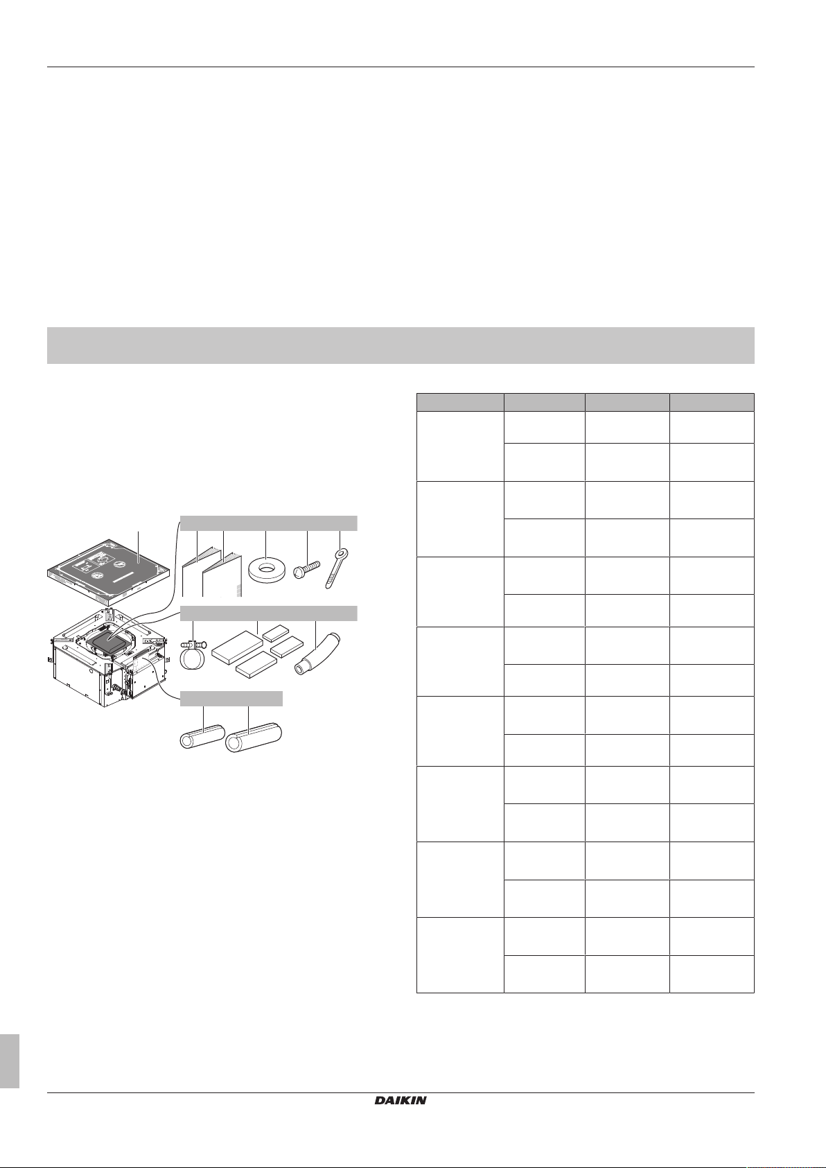
4× 7×8×1× 1×
a
4×
1×
1×
1×
1×
e fdcb
g h
i
j k
▪ General safety precautions:
▪ Safety instructions that you must read before installing
▪ Format: Paper (in the box of the indoor unit)
▪ Indoor unit installation and operation manual:
▪ Installation and operation instructions
▪ Format: Paper (in the box of the indoor unit)
▪ Installer and user reference guide:
▪ Preparation of the installation, good practices, reference data,…
▪ Detailed step-by-step instructions and background information
for basic and advanced usage
▪ Format: Digital files on http://www.daikineurope.com/support-
and-manuals/product-information/
For the installer
2 About the box
2.1 Indoor unit
2.1.1 To remove the accessories from the indoor unit
a Paper pattern for installation (upper part of packing)
b General safety precautions
c Indoor unit installation and operation manual
d Washers for hanger bracket
e Screws
f Cable ties
g Metal clamp
h Sealing pads: Large (drain pipe), medium 1 (gas pipe),
medium 2 (liquid pipe), small (electrical wiring)
i Drain hose
j Insulation piece: Small (liquid pipe)
k Insulation piece: Large (gas pipe)
3 About the units and options
3.1 About the indoor unit
Use the system in the following temperature and humidity ranges for
safe and effective operation.
For combination with R410A outdoor unit, refer to the following table:
Latest revisions of the supplied documentation may be available on
the regional Daikin website or via your dealer.
The original documentation is written in English. All other languages
are translations.
Technical engineering data
▪ A subset of the latest technical data is available on the regional
Daikin website (publicly accessible).
▪ The full set of latest technical data is available on the Daikin
extranet (authentication required).
Outdoor units Cooling Heating
RR71~125 Outdoor
temperature
Indoor
temperature
RQ71~125 Outdoor
temperature
Indoor
temperature
RXS25~60 Outdoor
temperature
Indoor
temperature
2MXS50 Outdoor
temperature
Indoor
temperature
3MXS40~68
4MXS68~80
5MXS90
RZQG71~140 Outdoor
RZQSG71~140 Outdoor
RZQ200~250 Outdoor
For combination with R32 outdoor unit, refer to the following table:
Outdoor
temperature
Indoor
temperature
temperature
Indoor
temperature
temperature
Indoor
temperature
temperature
Indoor
temperature
–15~46°CDB —
18~37°CDB
12~28°CWB
–5~46°CDB –9~21°CDB
18~37°CDB
12~28°CWB
–10~46°CDB –15~24°CDB
18~32°CDB 10~30°CDB
10~46°CDB –15~24°CDB
18~32°CDB 10~30°CDB
–10~46°CDB –15~24°CDB
18~32°CDB 10~30°CDB
–15~50°CDB –19~21°CDB
18~37°CDB
12~28°CWB
–15~46°CDB –14~21°CDB
20~37°CDB
14~28°CWB
–5~46°CDB –14~21°CDB
20~37°CDB
14~28°CWB
—
–10~15°CWB
10~27°CDB
–16~18°CWB
–16~18°CWB
–16~18°CWB
–20~15.5°CWB
10~27°CDB
–15~15.5°CWB
10~27°CDB
–15~15°CWB
10~27°CDB
Installation and operation manual
4
Split system air conditioners
FFA25~60A2VEB
4P456960-1 – 2017.03
4 Preparation
a
b
c
d
e
i
f
g
h
(mm)
≥1500
≥1500
≥
2000
≥
4000
≥1500
A
B
C
ba dac
Outdoor units Cooling Heating
RXM25~60 Outdoor
temperature
Indoor
–10~46°CDB –15~24°CDB
–16~18°CWB
18~32°CDB 10~30°CDB
temperature
2MXM50
3MXM40~68
4MXM68~80
5MXM90
RZAG71~140 Outdoor
RZASG71~140 Outdoor
Indoor humidity ≤80%
Outdoor
temperature
Indoor
–10~46°CDB –15~24°CDB
–16~18°CWB
18~32°CDB 10~30°CDB
temperature
–20~52°CDB –19.5~21°CDB
temperature
Indoor
temperature
18~37°CDB
12~28°CWB
–20~15.5°CWB
10~27°CDB
–15~46°CDB –14~21°CDB
temperature
Indoor
temperature
(a) To avoid condensation and water dripping out of the unit. If
the temperature or the humidity is beyond these conditions,
safety devices may be put in action and the air conditioner
may not operate.
20~37°CDB
14~28°CWB
–15~15.5°CWB
10~27°CDB
(a)
4 Preparation
4.1 Preparing installation site
4.1.1 Installation site requirements of the indoor unit
INFORMATION
The sound pressure level is less than 70dBA.
CAUTION
Appliance not accessible to the general public, install it in a
secured area, protected from easy access.
This unit, both indoor and outdoor, is suitable for
installation in a commercial and light industrial
environment.
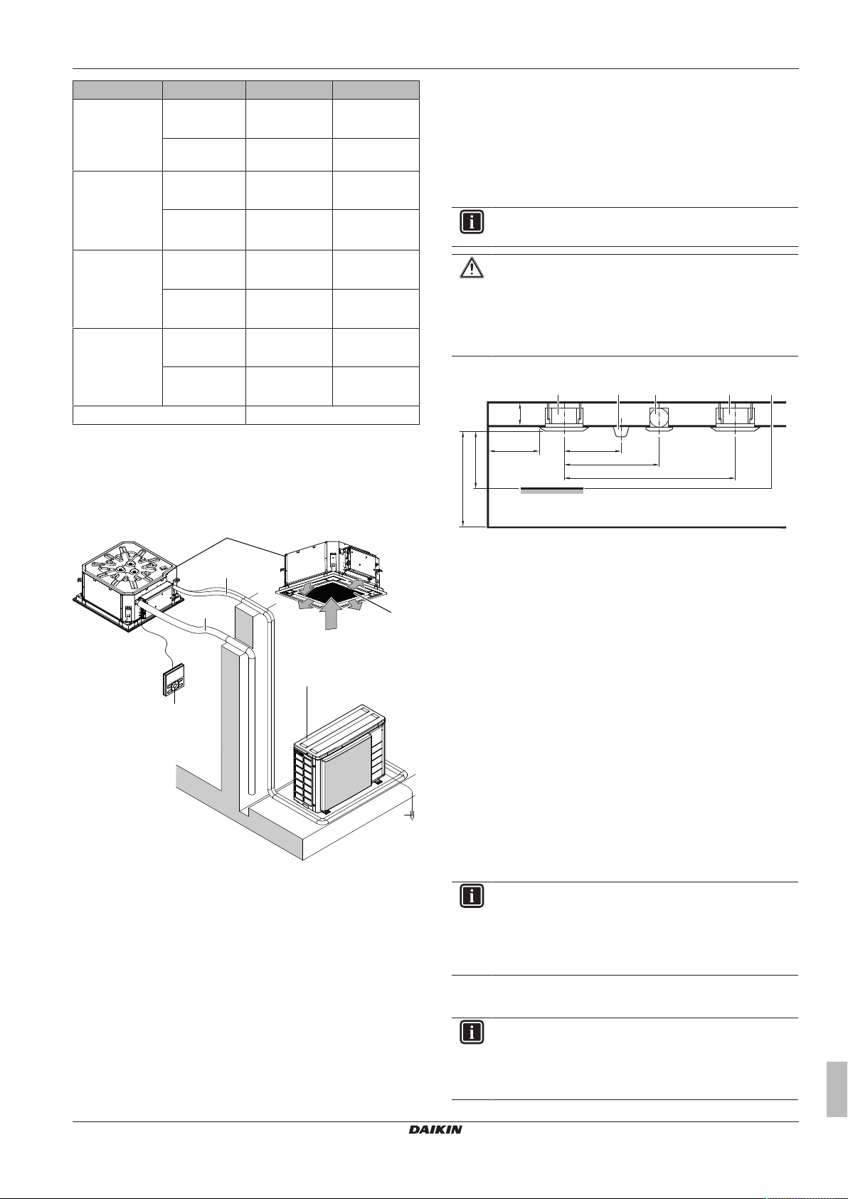
▪ Spacing. Mind the following requirements:
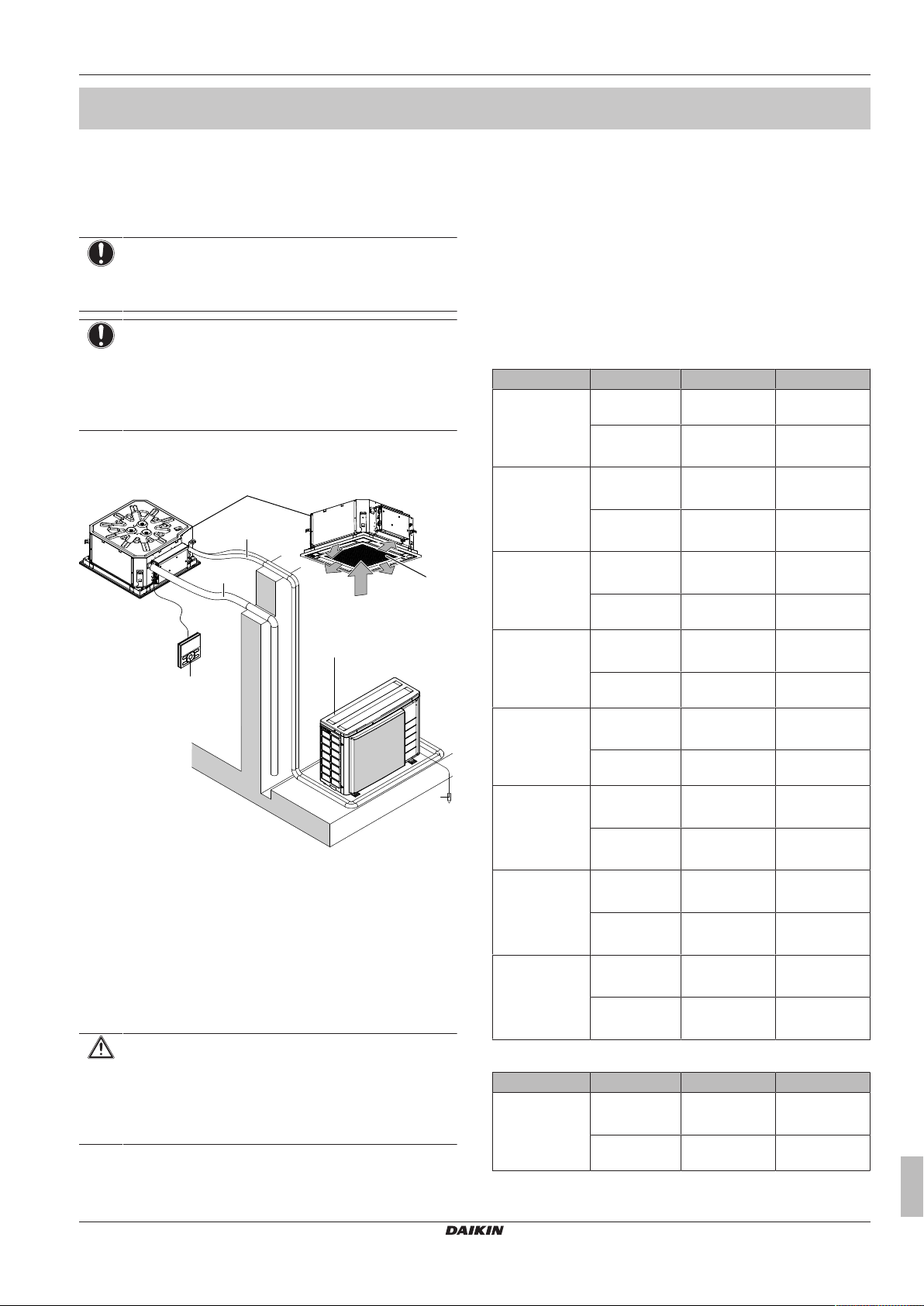
3.2 System layout
a Indoor unit
b Outdoor unit
c User interface
d Suction air
e Discharge air
f Refrigerant piping + interconnection cable
g Drain pipe
h Earth wiring
i Suction grille and air filter
A Minimum distance to the wall
B Minimum and maximum distance to the floor (see below)
C ≥295mm: In case of installation with BYFQ60B
≥300mm: In case of installation with BYFQ60C
a Indoor unit
b Lighting (the figure shows ceiling-mounted lighting, but
recessed lighting is also allowed)
c Air fan
d Static volume (example: table)
▪ Minimum and maximum distance to the floor:
▪ Minimum: 2.5m to avoid accidental touching.
▪ Maximum: Depends on the air flow directions and the capacity
class. Also make sure the "Ceiling height" field setting
corresponds with the actual situation. See Field settings.
5 Installation
5.1 Mounting the indoor unit
5.1.1 Precautions when mounting the indoor unit
INFORMATION
Also read the precautions and requirements in the
following chapters:
▪ General safety precautions
▪ Preparation
5.1.2 Guidelines when installing the indoor unit
FFA25~60A2VEB
Split system air conditioners
4P456960-1 – 2017.03
INFORMATION
Optional equipment. When installing optional equipment,
also read the installation manual of the optional equipment.
Depending on the field conditions, it might be easier to
install the optional equipment first.
Installation and operation manual
5
5 Installation
A
c
b
d
e
a
(mm)
a1
b
b
a2
c
4×
533
533
a cb d
(mm)
c
d
A
B
A
B
533
350
575
c
d
533
575
b
a
A
C
B
c
bba
▪ Decoration panel. Install the decoration panel always after
installing the unit.
▪ Ceiling strength. Check whether the ceiling is strong enough to
support the weight of the unit. If there is a risk, reinforce the ceiling
before installing the unit.
▪ For existing ceilings, use anchors.
▪ For new ceilings, use sunken inserts, sunken anchors or other
field supplied parts.
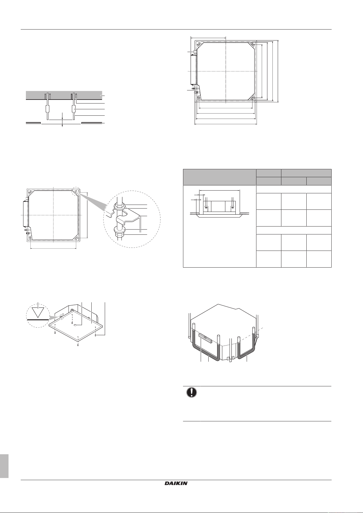
A 50~100mm
a Ceiling slab
b Anchor
c Long nut or turnbuckle
d Suspension bolt
e Suspended ceiling
▪ Suspension bolts. Use M8~M10 suspension bolts for installation.
Attach the hanger bracket to the suspension bolt. Fix it securely
using a nut and washer from the upper and lower sides of the
hanger bracket.
a1 Nut (field supply)
a2 Double nut (field supply)
b Washer (accessories)
c Hanger bracket (attached to the unit)
▪ Paper pattern for installation (upper part of the packing). Use
the paper pattern to determine the correct horizontal positioning. It
contains the necessary dimensions and centers. You can attach
the paper pattern to the unit.
A 585~660mm: In case of installation with BYFQ60B
585~595 mm: In case of installation with BYFQ60C
B 700mm: In case of installation with BYFQ60B
620 mm: In case of installation with BYFQ60C
a Drain piping
b Refrigerant piping
c Hanger bracket pitch (suspension)
d Unit
Then
If A B C
BYFQ60B
585mm
5mm 57.5mm
(= min.)
660mm
42.5mm 20mm
(= max.)
BYFQ60C
585mm
5mm 17.5mm
(= min.)
595mm
10mm 12.5mm
(= max.)
A Ceiling opening
B Distance between the unit and the ceiling opening
C Overlap between the decoration panel and the suspended
ceiling
▪ Level. Make sure the unit is level at all 4 corners using a level or a
water-filled vinyl tube.
a Centre of the unit
b Centre of the ceiling opening
c Paper pattern for installation (upper part of the packing)
d Screws (accessories)
▪ Ceiling opening and unit:
▪ Make sure the ceiling opening is within the following limits:
Minimum: 585mm to be able to fit the unit.
Maximum: 660 mm in case of installation with BYFQ60B and
595 mm in case of installation with BYFQ60C ensure enough
overlapping between the decoration panel and the suspended
ceiling. If the ceiling opening is larger, add extra ceiling
material.
▪ Make sure the unit and its hanger brackets (suspension) are
centered within the ceiling opening.
Installation and operation manual
6
a Level
b Vinyl tube
c Water level
NOTICE
Do NOT install the unit tilted. Possible consequence: If
the unit is tilted against the direction of the condensate flow
(the drain piping side is raised), the float switch might
malfunction and cause water to drip.
5.1.3 Guidelines when installing the drain piping
Make sure condensation water can be evacuated properly. This
involves:
▪ General guidelines
▪ Connecting the drain piping to the indoor unit
FFA25~60A2VEB
Split system air conditioners
4P456960-1 – 2017.03
5 Installation
1~1.5 m
a
A
B
≤300
0~75
1000~1500
(mm)
ba
b c
a
dd
≥100
A
(mm)
a
≤4 mm
A
A'
A-A'
A
A'
f
652
ce
4
ba
d
b
a
d
c
3
1
2~61
▪ Checking for water leaks
General guidelines
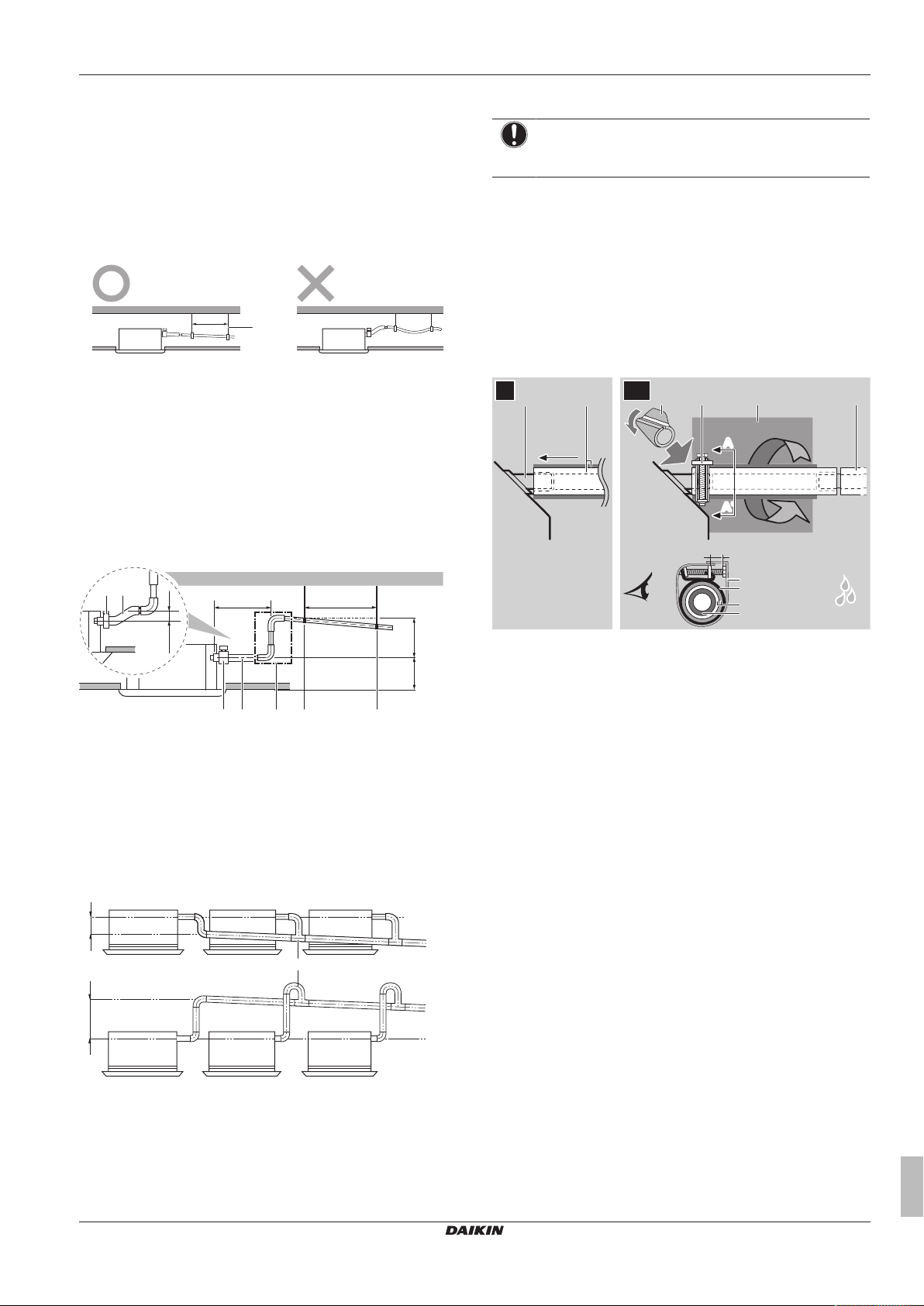
▪ Pipe length. Keep drain piping as short as possible.
▪ Pipe size. Keep the pipe size equal to or greater than that of the
connecting pipe (vinyl pipe of 25 mm nominal diameter and
32mm outer diameter).
▪ Slope. Make sure the drain piping slopes down (at least 1/100) to
prevent air from being trapped in the piping. Use hanging bars as
shown.
a Hanging bar
O Allowed
X Not allowed
▪ Condensation. Take measures against condensation. Insulate
the complete drain piping in the building.
▪ Rising piping. If necessary to make the slope possible, you can
install rising piping.
▪ Drain hose inclination: 0~75mm to avoid stress on the piping
and to avoid air bubbles.
▪ Rising piping: ≤300 mm from the unit, ≤630~675 mm
(depending on the decoration panel used) perpendicular to the
unit.
To connect the drain piping to the indoor unit
NOTICE
Incorrect connection of the drain hose might cause leaks,
and damage the installation space and surroundings.
1 Push the drain hose as far as possible over the drain pipe
connection.
2 Tighten the metal clamp until the screw head is less than 4mm
from the metal clamp part.
3 Check for water leaks (see "To check for water leaks" on
page7).
4 Install the insulation piece (drain pipe).
5 Wind the large sealing pad (= insulation) around the metal
clamp and drain hose, and fix it with cable ties.
6 Connect the drain piping to the drain hose.
A ≤645mm: In case of installation with BYFQ60B
≤630mm: In case of installation with BYFQ60C
B 205mm: In case of installation with BYFQ60B
220mm: In case of installation with BYFQ60C
a Metal clamp (accessory)
b Drain hose (accessory)
c Rising drain piping (vinyl pipe of 25mm nominal diameter
and 32mm outer diameter) (field supply)
d Hanging bars (field supply)
▪ Combining drain pipes. You can combine drain pipes. Make
sure to use drain pipes and T-joints with the correct gauge for the
operating capacity of the units.
A ≤645mm: In case of installation with BYFQ60B
a T-joint
≤630mm: In case of installation with BYFQ60C
a Drain pipe connection (attached to the unit)
b Drain hose (accessory)
c Metal clamp (accessory)
d Large sealing pad (accessory)
e Insulation piece (drain pipe) (accessory)
f Drain piping (field supply)
To check for water leaks
The procedure differs depending on whether electrical wiring is
already finished. When electrical wiring is not finished yet, you need
to temporarily connect the user interface and power supply to the
unit.
When electrical wiring is not finished yet
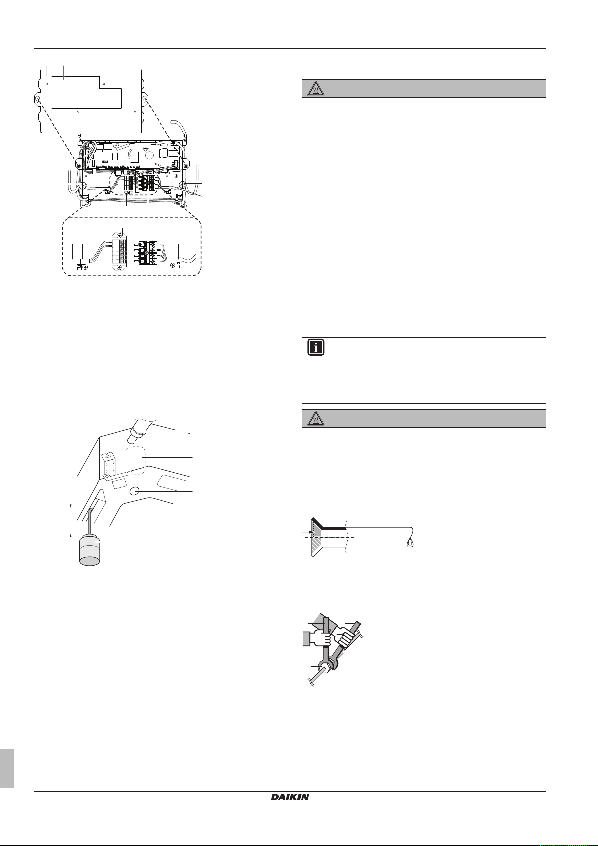
1 Temporarily connect electrical wiring.
▪ Remove the control box cover (a).
▪ Connect the single-phase power supply (50Hz, 230V) to
connections No. 1 and No. 2 on the terminal block for power
supply (d) and earth (c).
▪ Reattach the control box cover (a).
FFA25~60A2VEB
Split system air conditioners
4P456960-1 – 2017.03
Installation and operation manual
7
5 Installation
g
g
b
d
f
a h
i e
e
b
f
d
c
P1P2
TRANSM.
WIRING
F1 F2
OFF
FORCED
T1 T2
RC
≥100 mm
e
d
c
b
a
a
b
c
d
a Control box cover
b Inter-unit wiring
c Earth cable
d Terminal block for power supply
e Clamp
f Terminal board for transmission wiring
g Opening for cables
h Wiring diagram label (on the back of the control box lid)
i Remote controller wiring
2 Turn ON the power.
3 Start cooling operation (see "7.4 To perform a test run" on
page12).
4 Gradually pour approximately 1 l of water through the air
discharge outlet, and check for leaks.
5.2 Connecting the refrigerant piping
DANGER: RISK OF BURNING
5.2.1 About connecting the refrigerant piping
Before connecting the refrigerant piping
Make sure the outdoor and indoor unit are mounted.
Typical workflow
Connecting the refrigerant piping involves:
▪ Connecting the refrigerant piping to the outdoor unit
▪ Connecting the refrigerant piping to the indoor unit
▪ Insulating the refrigerant piping
▪ Keeping in mind the guidelines for:
▪ Pipe bending
▪ Flaring pipe ends
▪ Brazing
▪ Using the stop valves
5.2.2 Precautions when connecting the refrigerant piping
INFORMATION
Also read the precautions and requirements in the
following chapters:
▪ General safety precautions
▪ Preparation
DANGER: RISK OF BURNING
a Plastic watering can
b Service drain outlet (with rubber plug). Use this outlet to
drain water from the drain pan.
c Drain pump location
d Drain pipe connection
e Drain pipe
5 Turn OFF the power.
6 Disconnect the electrical wiring.
▪ Remove the control box cover.
▪ Disconnect the power supply and earth.
▪ Reattach the control box cover.
When electrical wiring is finished already
1 Start cooling operation (see "7.4 To perform a test run" on
page12).
2 Gradually pour approximately 1 l of water through the air
discharge outlet, and check for leaks (see When electrical
wiring is not finished yet).
Installation and operation manual
8
5.2.3 Guidelines when connecting the refrigerant piping
Take the following guidelines into account when connecting pipes:
▪ Coat the flare inner surface with ether oil or ester oil when
connecting a flare nut. Tighten 3 or 4 turns by hand, before
tightening firmly.
▪ Always use 2 wrenches together when loosening a flare nut.
▪ Always use a spanner and torque wrench together to tighten the
flare nut when connecting the piping. This to prevent nut cracking
and leaks.
a Torque wrench
b Spanner
c Piping union
d Flare nut
FFA25~60A2VEB
Split system air conditioners
4P456960-1 – 2017.03

5 Installation
R=0.4~0.8
45°
±2
90°
±2
A
a b
A
a b
c
a b c d e
f
f
A B
a dc e fb b
a dc e fb b
2
4
3
g
1
23
4
g
AB
1
Piping size
(mm)
Tightening
torque (N•m)
Flare
dimensions (A)
Flare shape
(mm)
(mm)
Ø6.4 15~17 8.7~9.1
Ø9.5 33~39 12.8~13.2
Ø12.7 50~60 16.2~16.6
5.2.4 Pipe bending guidelines
Use a pipe bender for bending. All pipe bends should be as gentle
as possible (bending radius should be 30~40mm or larger).
5.2.5 To flare the pipe end
CAUTION
▪ Incomplete flaring may cause refrigerant gas leakage.
▪ Do NOT re-use flares. Use new flares to prevent
refrigerant gas leakage.
▪ Use flare nuts that are included with the unit. Using
different flare nuts may cause refrigerant gas leakage.
1 Cut the pipe end with a pipe cutter.
2 Remove burrs with the cut surface facing down so that the
chips do not enter the pipe.
a Cut exactly at right angles.
b Remove burrs.
3 Remove the flare nut from the stop valve and put the flare nut
on the pipe.
4 Flare the pipe. Set exactly at the position as shown in the
following illustration.
a Refrigerant piping
b Part to be brazed
c Taping
d Manual valve
e Pressure-reducing valve
f Nitrogen
▪ Do NOT use anti-oxidants when brazing pipe joints.
Residue can clog pipes and break equipment.
▪ Do NOT use flux when brazing copper-to-copper refrigerant
piping. Use phosphor copper brazing filler alloy (BCuP), which
does not require flux.
Flux has an extremely harmful influence on refrigerant piping
systems. For instance, if chlorine based flux is used, it will cause
pipe corrosion or, in particular, if the flux contains fluorine, it will
deteriorate the refrigerant oil.
5.2.7 To connect the refrigerant piping to the indoor unit
WARNING: FLAMMABLE MATERIAL
The R32 refrigerant (if applicable) in this unit is mildly
flammable.
▪ Pipe length. Keep refrigerant piping as short as possible.
▪ Flare connections. Connect refrigerant piping to the unit using
flare connections.
▪ Insulation. Insulate the refrigerant piping on the indoor unit as
follows:
(a)
(a) Refer to the outdoor unit specifications for the type of
refrigerant to be used.
Flare tool for
R410A or R32
(clutch type)
Conventional flare tool
Clutch type
(Ridgid-type)
Wing nut type
(Imperial-type)
A 0~0.5mm 1.0~1.5mm 1.5~2.0mm
5 Check that the flaring is properly made.
a Flare’s inner surface must be flawless.
b The pipe end must be evenly flared in a perfect circle.
c Make sure the flare nut is fitted.
5.2.6 To braze the pipe end
The indoor unit and outdoor unit have flare connections. Connect
both ends without brazing. If brazing should be needed, take the
following into account:
▪ When brazing, blow through with nitrogen to prevent creation of
large quantities of oxidised film on the inside of the piping. This
film adversely affects valves and compressors in the refrigerating
system and prevents proper operation.
▪ Set the nitrogen pressure to 20 kPa (0.2 bar) (just enough so it
can be felt on the skin) with a pressure-reducing valve.
A Gas piping
B Liquid piping
a Insulation material (field supply)
b Cable tie (accessory)
c Insulation pieces: Large (gas pipe), small (liquid pipe)
(accessories)
d Flare nut (attached to the unit)
e Refrigerant pipe connection (attached to the unit)
f Unit
g Sealing pads: Medium 1 (gas pipe), medium 2 (liquid pipe)
(accessories)
1 Turn up the seams of the insulation pieces.
2 Attach to the base of the unit.
3 Tighten the cable ties on the insulation pieces.
4 Wrap the sealing pad from the base of the unit to the top of
the flare nut.
NOTICE
Make sure to insulate all refrigerant piping. Any exposed
piping might cause condensation.
5.3 Connecting the electrical wiring
DANGER: RISK OF ELECTROCUTION
FFA25~60A2VEB
Split system air conditioners
4P456960-1 – 2017.03
Installation and operation manual
9

5 Installation
1~ 50 Hz
220-240 V
b
a
e1
c
d
WARNING
ALWAYS use multicore cable for power supply cables.
WARNING
If the supply cord is damaged, it must be replaced by the
manufacturer, its service agent or similarly qualified
persons in order to avoid a hazard.
5.3.1 About connecting the electrical wiring
Typical workflow
Connecting the electrical wiring typically consists of the following
stages:
1 Making sure the power supply system complies with the
electrical specifications of the units.
2 Connecting the electrical wiring to the outdoor unit.
3 Connecting the electrical wiring to the indoor unit.
4 Connecting the main power supply.
5.3.2 Precautions when connecting the
electrical wiring
INFORMATION
Also read the precautions and requirements in the
following chapters:
▪ General safety precautions
▪ Preparation
DANGER: RISK OF ELECTROCUTION
WARNING
ALWAYS use multicore cable for power supply cables.
WARNING
If the supply cord is damaged, it must be replaced by the
manufacturer, its service agent or similarly qualified
persons in order to avoid a hazard.
5.3.3 Guidelines when connecting the electrical
wiring
Tightening torques
Wiring Screw size Tightening torque
(N•m)
Interconnection
cable
(indoor↔outdoor)
User interface cable M3.5 0.79~0.97
M4 1.18~1.44
5.3.5 To connect the electrical wiring on the indoor unit
NOTICE
▪ Follow the wiring diagram (delivered with the unit,
located at the inside of the service cover).
▪ For instructions on how to connect the decoration panel
and the sensor kit, see the wiring instruction sheet
(delivered with the unit, inside the accessory bag).
▪ Make sure the electrical wiring does NOT obstruct
proper reattachment of the service cover.
It is important to keep the power supply and the transmission wiring
separated from each other. In order to avoid any electrical
interference the distance between both wiring should always be at
least 50mm.
NOTICE
Be sure to keep the power line and transmission line apart
from each other. Transmission wiring and power supply
wiring may cross, but may not run parallel.
1 Remove the service cover.
2 User interface cable: Route the cable through the frame,
connect the cable to the terminal block, and fix the cable with a
cable tie.
3 Interconnection cable (indoor↔outdoor): Route the cable
through the frame, connect the cable to the terminal block
(make sure the numbers match with the numbers on the
outdoor unit, and connect the earth wire), and fix the cable with
a cable tie.
4 Divide the small sealing (accessory) and wrap it around the
cables to prevent water from entering the unit. Seal all gaps to
prevent small animals from entering the system.
WARNING
Provide adequate measures to prevent that the unit can be
used as a shelter by small animals. Small animals that
make contact with electrical parts can cause malfunctions,
smoke or fire.
5 Reattach the service cover.
▪ Following installation is for pair type or multi-system. For more
installation options, see the Installer reference guide of the indoor
unit.
5.3.4 Specifications of standard wiring components
Component Specification
Interconnection cable
(indoor↔outdoor)
User interface cable Vinyl cords with 0.75 to
Installation and operation manual
Minimum cable section of
2.5mm² and applicable for
1.25mm² sheath or cables
(2‑core wires)
Maximum 500m
10
230V
a Interconnection cable
b Power supply cable
c Earth leakage circuit breaker
d Fuse
e1 Main user interface
FFA25~60A2VEB
Split system air conditioners
4P456960-1 – 2017.03
6 Configuration
a b c
6 Configuration
6.1 Field settings
Make the following field settings so that they correspond with the
actual installation setup and with the needs of the user:
▪ Ceiling height
▪ Air flow direction
▪ Air volume when thermostat control is OFF
▪ Time to clean air filter
Setting: Ceiling height
This setting must correspond with the actual distance to the floor,
capacity class and air flow directions.
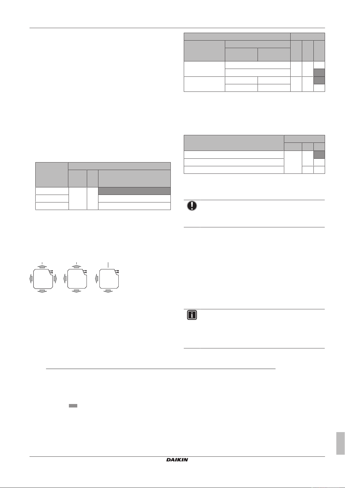
▪ For 3-way and 4-way air flows (which require an optional blocking
pad kit), see the installation manual of the optional blocking pad
kit.
▪ For all-round air flow, use the table below.
If the
distance to
the floor is
M C1 C2
(m)
≤2.7 13 (23) 0 01
2.7<x≤3.0 02
3.0<x≤3.5 03
Setting: Air flow direction
This setting must correspond with the actual used air flow directions.
See the installation manual of the optional blocking pad kit and the
manual of the user interface.
Default: 01 (= all-round air flow)
Example:
a All-round air flow
b 3-way air flow (1 air outlet closed) (optional blocking pad kit
required)
c 2-way air flow (2 air outlets closed) (optional blocking pad
kit required)
Setting: Air volume when thermostat control is OFF
This setting must correspond with the needs of the user. It
determines the fan speed of the indoor unit during thermostat OFF
condition.
1 If you have set the fan to operate, set the air volume speed:
Then
1
If you want Then
1
Outdoor unit M C1 C2
General 2MX+3MX
+4MX+5MX
During cooling
operation
During heating
operation
2
LL
Setup volume
2
LL
2
Monitoring 1212
Setup volume2Monitoring 2
12
6 01
(22)
02
3 01
2
(22)
02
Setting: Time to clean air filter
This setting must correspond with the air contamination in the room.
It determines the interval at which the TIME TO CLEAN AIR FILTER
notification is displayed on the user interface. When using a wireless
user interface, you must also set the address (see the installation
manual of the user interface).
If you want an interval of…
(air contamination)
M C1 C2
Then
1
±2500h (light) 10 (20) 0 01
±1250h (heavy) 02
No notification 3 02
7 Commissioning
NOTICE
NEVER operate the unit without thermistors and/or
pressure sensors/switches. Burning of the compressor
might result.
7.1 Overview: Commissioning
This chapter describes what you have to do and know to
commission the system after it is installed.
Typical workflow
Commissioning typically consists of the following stages:
1 Checking the "Checklist before commissioning".
2 Performing a test run for the system.
7.2 Precautions when commissioning
INFORMATION
During the first running period of the unit, the required
power may be higher than stated on the nameplate of the
unit. This phenomenon is caused by the compressor, that
needs a continuous run time of 50 hours before reaching
smooth operation and stable power consumption.
(1)
Field settings are defined as follows:
▪ M: Mode number – First number: for group of units – Number between brackets: for individual unit
▪ C1: First code number
▪ C2: Second code number
▪ : Default
(2)
Fan speed:
▪ LL: Low fan speed
▪ Setup volume: The fan speed corresponds to the speed the user has set (low, medium, high) using the fan speed button
on the user interface.
▪ Monitoring 1, 2: The fan is OFF, but runs for a short time every 6minutes to detect the room temperature by Low fan
speed (1) or by Setup volume (2).
FFA25~60A2VEB
Split system air conditioners
4P456960-1 – 2017.03
Installation and operation manual
11

7 Commissioning
A B
Cool
Set to
28°C
Return Setting
Service Settings 1/3
Test Operation
Maintenance Contact
Field Settings
Demand
Min Setpoints Differential
Group Address
Cool
Return Setting
Test Operation
NOTICE
Before starting up the system, the unit MUST be energised
for at least 6 hours. The crankcase heater needs to heat
up the compressor oil to avoid oil shortage and
compressor breakdown during startup.
NOTICE
NEVER operate the unit without thermistors and/or
pressure sensors/switches. Burning of the compressor
might result.
NOTICE
Do NOT operate the unit until the refrigerant piping is
complete (when operated this way, the compressor will
break).
NOTICE
Cooling operation mode. Perform the test run in cooling
operation mode so that stop valves failing to open can be
detected. Even if the user interface was set to heating
operation mode, the unit will run in cooling operation mode
during 2‑3 minutes (although the user interface will display
the heating icon), and then automatically switch to heating
operation mode.
NOTICE
If you cannot operate the unit in test run, see "7.5 Error
codes when performing a test run"on page13.
The stop valves (gas and liquid) on the outdoor unit are
fully open.
7.4 To perform a test run
This task is only applicable when using the BRC1E52 or BRC1E53
user interface. When using any other user interface, see the
installation manual or service manual of the user interface.
NOTICE
Do not interrupt the test run.
INFORMATION
Backlight. To perform an ON/OFF action on the user
interface, the backlight does not need to be lit. For any
other action, it needs to be lit first. The backlight is lit for
±30seconds when you press a button.
1 Perform introductory steps.
# Action
1 Open the liquid stop valve (A) and gas stop valve (B)
by removing the stem cap and turning
counterclockwise with a hex wrench until it stops.
WARNING
If the panels on the indoor units are not installed yet, make
sure to power OFF the system after finishing the test run.
To do so, turn OFF operation via the user interface. Do
NOT stop operation by turning OFF the circuit breakers.
7.3 Checklist before commissioning
Do NOT operate the system before the following checks are OK:
You read the complete installation instructions, as
described in the installer reference guide.
The indoor units are properly mounted.
In case a wireless user interface is used: The indoor unit
decoration panel with infrared receiver is installed.
The outdoor unit is properly mounted.
There are NO missing phases or reversed phases.
The system is properly earthed and the earth terminals
are tightened.
The fuses or locally installed protection devices are
installed according to this document, and have not been
bypassed.
The power supply voltage matches the voltage on the
identification label of the unit.
There are NO loose connections or damaged electrical
components in the switchbox.
The insulation resistance of the compressor is OK.
2 Close the service cover to prevent electric shocks.
3 Turn ON power for at least 6hours before starting
operation to protect the compressor.
4 On the user interface, set the unit to cooling operation
mode.
2 Start the test run
# Action Result
1 Go to the home menu.
2 Press at least 4seconds. The Service Settings menu
is displayed.
3 Select Test Operation.
4 Press. Test Operation is
displayed on the home
menu.
There are NO damaged components or squeezed
pipes on the inside of the indoor and outdoor units.
There are NO refrigerant leaks.
The correct pipe size is installed and the pipes are
properly insulated.
Installation and operation manual
12
5 Press within 10seconds. Test run starts.
FFA25~60A2VEB
Split system air conditioners
4P456960-1 – 2017.03

8 Disposal
Return Setting
Return Setting
Air Volume/direction
Air Volume Direction
Position 0
Low
Return Setting
Return Setting
Air Volume/direction
Air Volume Direction
Low
Position 0
Return Setting
Service Settings 1/3
Test Operation
Maintenance Contact
Field Settings
Demand
Min Setpoints Differential
Group Address
b
a
c
3 Check operation for 3minutes.
4 Check operation of the airflow direction.
# Action Result
1 Press.
2 Select Position 0.
3 Change the position. If the airflow flap of the
indoor unit moves,
operation is OK.
If not, operation is not OK.
4 Press. The home menu is
displayed.
5 Stop the test run.
# Action Result
1 Press at least 4seconds. The Service Settings menu
is displayed.
Error code Possible cause
U2 ▪ There is a voltage imbalance.
▪ There is a missing phase in case of
three-phase power supply units. Note:
Operation will be impossible. Turn OFF
the power, recheck the wiring, and switch
two of the three electrical wires.
U4 or UF The inter-unit branch wiring is not correct.
UA The outdoor and indoor unit are
incompatible.
8 Disposal
NOTICE
Do not try to dismantle the system yourself: the dismantling
of the system, treatment of the refrigerant, oil and other
parts must comply with applicable legislation. Units must
be treated at a specialized treatment facility for reuse,
recycling and recovery.
9 Technical data
▪ A subset of the latest technical data is available on the regional
Daikin website (publicly accessible).
▪ The full set of latest technical data is available on the Daikin
extranet (authentication required).
2 Select Test Operation.
3 Press. The unit returns to normal
operation, and the home
menu is displayed.
7.5 Error codes when performing a test run
If the installation of the outdoor unit has NOT been done correctly,
the following error codes may be displayed on the user interface:
Error code Possible cause
Nothing displayed
(the currently set
temperature is not
displayed)
E3, E4 or L8 ▪ The stop valves are closed.
E7 There is a missing phase in case of three-
L4 The air inlet or air outlet is blocked.
U0 The stop valves are closed.
▪ The wiring is disconnected or there is a
wiring error (between power supply and
outdoor unit, between outdoor unit and
indoor units, between indoor unit and
user interface).
▪ The fuse on the outdoor or indoor unit
PCB has blown.
▪ The air inlet or air outlet is blocked.
phase power supply units.
Note: Operation will be impossible. Turn
OFF the power, recheck the wiring, and
switch two of the three electrical wires.
9.1 Piping diagram: Indoor unit
a Liquid pipe connection
b Gas pipe connection
c Heat exchanger
FFA25~60A2VEB
Split system air conditioners
4P456960-1 – 2017.03
Installation and operation manual
13

9 Technical data
Unified Wiring Diagram Legend
For applied parts and numbering refer to the wiring diagram sticker supplied on the unit. Part numbering is realized by Arabic numbers in ascending order for each part and
is represented in the overview below by symbol “*” in the part code.
: CIRCUIT BREAKER : PROTECTIVE EARTH
: CONNECTION : PROTECTIVE EARTH (SCREW)
,
: CONNECTOR
A
: RECTIFIER
: EARTH : RELAY CONNECTOR
: FIELD WIRING : SHORT CIRCUIT CONNECTOR
: FUSE : TERMINAL
INDOOR
: INDOOR UNIT : TERMINAL STRIP
OUTDOOR
: OUTDOOR UNIT : WIRE CLAMP
BLK : BLACK GRN : GREEN PNK : PINK WHT : WHITE
BLU : BLUE GRY : GREY PRP, PPL : PURPLE YLW : YELLOW
BRN : BROWN ORG : ORANGE RED : RED
A*P : PRINTED CIRCUIT BOARD PS : SWITCHING POWER SUPPLY
BS* : PUSH BUTTON ON / OFF, OPERATION SWITCH PTC* : THERMISTOR PTC
BZ, H*O : BUZZER Q* : INSULATED GATE BIPOLAR TRANSISTOR (IGBT)
C* : CAPACITOR Q*DI : EARTH LEAK CIRCUIT BREAKER
AC*, CN*, E*, HA*, HE, HL*, HN*,
HR*, MR*_A, MR*_B, S*, U, V,
W, X*A
: CONNECTION, CONNECTOR Q*L : OVERLOAD PROTECTOR
D*, V*D : DIODE Q*M : THERM
O SWITCH
DB* : DIODE BRIDGE R* : RESISTOR
DS* : DIP SWITCH R*T : THERMISTOR
E*H : HEATER RC : RECEIVER
F*U, FU*
(FOR CHARACTERISTICS
REFER TO PCB INSIDE YOUR UNIT)
: FUSE S*C : LIMIT SWITCH
FG* : CONNECTOR (FRAME GROUND) S*L : FLOAT SWITCH
H* : HARNESS S*NPH : PRESSURE SENSOR (HIGH)
H*P, LED*, V*L : PILOT LAMP, LIGHT EMITTING DIODE S*NPL : PRESSURE SENSOR (LOW)
HAP : LIGHT EMITTING DIODE (SERVICE MONITOR GREEN) S*PH, HPS* : PRESSURE SWITCH (HIGH)
HIGH VOLTAGE : HIGH VOLTAGE S*PL : PRESSURE SWITCH (L
OW)
IES : INTELLIGENT EYE SENSOR S*T : THERMOSTAT
IPM* : INTELLIGENT POWER MODULE S*W, SW* : OPERATION SWITCH
K*R, KCR, KFR, KHuR : MAGNETIC RELAY SA* : SURGE ARRESTOR
L : LIVE SR*, WLU : SIGNAL RECEIVER
L* : COIL SS* : SELECTOR SWITCH
L*R : REACTOR SHEET METAL : TERMINAL STRIP FIXED PLATE
M* : STEPPER MOTOR T*R : TRANSFORMER
M*C : COMPRESSOR MOTOR TC, TRC : TRANSMITTER
M*F : FAN MOTOR V*, R*V : VARISTOR
M*P : DRAIN PUMP MOTOR V*R : DIODE BRIDGE
M*S : SWING MOTOR WRC : WIRELESS REMOTE CONTROLLER
MR*, MRCW*, MRM*, MR
N* : MAGNETIC RELAY X* : TERMINAL
N : NEUTRAL X*M : TERMINAL STRIP (BLOCK)
n = * NUMBER OF PASSES THROUGH FERRITE CORE Y*E : ELECTRONIC EXPANSION VALVE COIL
PAM : PULSE-AMPLITUDE MODULATION Y*R, Y*S : REVERSING SOLENOID VALVE COIL
PCB* : PRINTED CIRCUIT BOARD Z*C : FERRITE CORE
PM* : POWER MODULE ZF, Z*F : NOISE FILTER
9.2 Wiring diagram
Installation and operation manual
14
Split system air conditioners
FFA25~60A2VEB
4P456960-1 – 2017.03
For the user
a
b
c
d
e
i
f
g
h
10 About the system
10 About the system
The indoor unit of this split system air conditioner can be used for
heating/cooling applications.
NOTICE
Do not use the system for other purposes. In order to avoid
any quality deterioration, do not use the unit for cooling
precision instruments, food, plants, animals or works of art.
NOTICE
For future modifications or expansions of your system:
A full overview of allowable combinations (for future
system extensions) is available in technical engineering
data and should be consulted. Contact your installer to
receive more information and professional advice.
10.1 System layout
a Indoor unit
b Outdoor unit
c User interface
d Suction air
e Discharge air
f Refrigerant piping + interconnection cable
g Drain pipe
h Earth wiring
i Suction grille and air filter
11 User interface
CAUTION
Never touch the internal parts of the controller.
Do not remove the front panel. Some parts inside are
dangerous to touch and appliance problems may happen.
For checking and adjusting the internal parts, contact your
dealer.
This operation manual will give a non-exhaustive overview of the
main functions of the system.
For more information about the user interface, see the operation
manual of the installed user interface.
12 Operation
12.1 Operation range
Use the system in the following temperature and humidity ranges for
safe and effective operation.
For combination with R410A outdoor unit, refer to the following table:
Outdoor units Cooling Heating
RR71~125 Outdoor
temperature
Indoor
temperature
RQ71~125 Outdoor
temperature
Indoor
temperature
RXS25~60 Outdoor
temperature
Indoor
temperature
2MXS50 Outdoor
temperature
Indoor
temperature
3MXS40~68
4MXS68~80
5MXS90
RZQG71~140 Outdoor
RZQSG71~140 Outdoor
RZQ200~250 Outdoor
For combination with R32 outdoor unit, refer to the following table:
Outdoor units Cooling Heating
RXM25~60 Outdoor
Outdoor
temperature
Indoor
temperature
temperature
Indoor
temperature
temperature
Indoor
temperature
temperature
Indoor
temperature
temperature
Indoor
temperature
–15~46°CDB —
18~37°CDB
12~28°CWB
–5~46°CDB –9~21°CDB
18~37°CDB
12~28°CWB
–10~46°CDB –15~24°CDB
18~32°CDB 10~30°CDB
10~46°CDB –15~24°CDB
18~32°CDB 10~30°CDB
–10~46°CDB –15~24°CDB
18~32°CDB 10~30°CDB
–15~50°CDB –19~21°CDB
18~37°CDB
12~28°CWB
–15~46°CDB –14~21°CDB
20~37°CDB
14~28°CWB
–5~46°CDB –14~21°CDB
20~37°CDB
14~28°CWB
–10~46°CDB –15~24°CDB
18~32°CDB 10~30°CDB
—
–10~15°CWB
10~27°CDB
–16~18°CWB
–16~18°CWB
–16~18°CWB
–20~15.5°CWB
10~27°CDB
–15~15.5°CWB
10~27°CDB
–15~15°CWB
10~27°CDB
–16~18°CWB
FFA25~60A2VEB
Split system air conditioners
4P456960-1 – 2017.03
Installation and operation manual
15
12 Operation
Outdoor units Cooling Heating
2MXM50
3MXM40~68
4MXM68~80
5MXM90
RZAG71~140 Outdoor
RZASG71~140 Outdoor
Indoor humidity ≤80%
Outdoor
temperature
Indoor
temperature
temperature
Indoor
temperature
temperature
Indoor
temperature
(a) To avoid condensation and water dripping out of the unit. If
the temperature or the humidity is beyond these conditions,
safety devices may be put in action and the air conditioner
may not operate.
–10~46°CDB –15~24°CDB
–16~18°CWB
18~32°CDB 10~30°CDB
–20~52°CDB –19.5~21°CDB
–20~15.5°CWB
18~37°CDB
12~28°CWB
–15~46°CDB –14~21°CDB
20~37°CDB
14~28°CWB
10~27°CDB
–15~15.5°CWB
10~27°CDB
(a)
12.2 Operating the system
12.2.1 About operating the system
▪ To protect the unit, turn on the main power switch 6 hours before
operation.
▪ If the main power supply is turned off during operation, operation
will restart automatically after the power turns back on again.
12.2.2 About cooling, heating, fan only, and automatic operation
▪ The air flow rate may adjust itself depending on the room
temperature or the fan may stop immediately. This is not a
malfunction.
12.2.3 About the heating operation
It may take longer to reach the set temperature for general heating
operation than for cooling operation.
The following operation is performed in order to prevent the heating
capacity from dropping or cold air from blowing.
Defrost operation
In heating operation, freezing of the outdoor unit's air cooled coil
increases over time, restricting the energy transfer to the outdoor
unit's coil. Heating capability decreases and the system needs to go
into defrost operation to be able to deliver enough heat to the indoor
units.
The indoor unit will stop fan operation, the refrigerant cycle will
reverse and energy from inside the building will be used to defrost
the outdoor unit coil.
The indoor unit will indicate defrost operation on the display .
Hot start
In order to prevent cold air from blowing out of an indoor unit at the
start of heating operation, the indoor fan is automatically stopped.
The display of the user interface shows . It may take some
time before the fan starts. This is not a malfunction.
12.2.4 To operate the system
1 Press the operation mode selector button on the user interface
several times and select the operation mode of your choice.
Cooling operation
Heating operation
Fan only operation
2 Press the ON/OFF button on the user interface.
Result: The operation lamp lights up and the system starts
operating.
12.3 Using the dry program
12.3.1 About the dry program
▪ The function of this program is to decrease the humidity in your
room with minimal temperature decrease (minimal room cooling).
▪ The micro computer automatically determines temperature and
fan speed (cannot be set by the user interface).
▪ The system does not go into operation if the room temperature is
low (<20°C).
12.3.2 To use the dry program
To start
1 Press the operation mode selector button on the user interface
several times and select (program dry operation).
2 Press the ON/OFF button of the user interface.
Result: The operation lamp lights up and the system starts
operating.
To stop
3 Press the ON/OFF button on the user interface once again.
Result: The operation lamp goes out and the system stops
operating.
NOTICE
Do not turn off power immediately after the unit stops, but
wait for at least 5 minutes.
12.4 Adjusting the air flow direction
Refer to the operation manual of the user interface.
12.4.1 About the air flow flap
Double flow+multi-flow units
For the following conditions, a micro computer controls the air flow
direction which may be different from the display.
Cooling Heating
▪ When the room temperature is
lower than the set
temperature.
▪ When operating continuously at horizontal air flow direction.
▪ When continuous operation with downward air flow is performed
at the time of cooling with a ceiling-suspended or a wall-mounted
unit, the micro computer may control the flow direction, and then
the user interface indication will also change.
The air flow direction can be adjusted in one of the following ways:
▪ The air flow flap itself adjusts its position.
▪ The air flow direction can be fixed by the user.
▪ Automatic and desired position .
▪ When starting operation.
▪ When the room temperature is
higher than the set
temperature.
▪ At defrost operation.
Installation and operation manual
16
Split system air conditioners
FFA25~60A2VEB
4P456960-1 – 2017.03
13 Maintenance and service
1
1
3
3
2
3
3
1
2
WARNING
Never touch the air outlet or the horizontal blades while the
swing flap is in operation. Fingers may become caught or
the unit may break down.
NOTICE
▪ The movable limit of the flap is changeable. Contact
your dealer for details. (only for double-flow, multi-flow,
corner, ceiling-suspended and wall-mounted).
▪ Avoid operating in the horizontal direction . It may
cause dew or dust to settle on the ceiling or flap.
13 Maintenance and service
NOTICE
Never inspect or service the unit by yourself. Ask a
qualified service person to perform this work. However, as
end user, you may clean the air filter, suction grille, air
outlet and outside panels.
WARNING
Never replace a fuse with a fuse of a wrong ampere ratings
or other wires when a fuse blows out. Use of wire or
copper wire may cause the unit to break down or cause a
fire.
▪ Depending on the settings, the user interface can display the
TIME TO CLEAN AIR FILTER notification. Clean the air filter
when the notification is displayed.
▪ If the dirt becomes impossible to clean, change the air filter
(=optional equipment).
How to clean the air filter:
NOTICE
Do NOT use water of 50°C or higher. Possible
consequence: Discoloration and deformation.
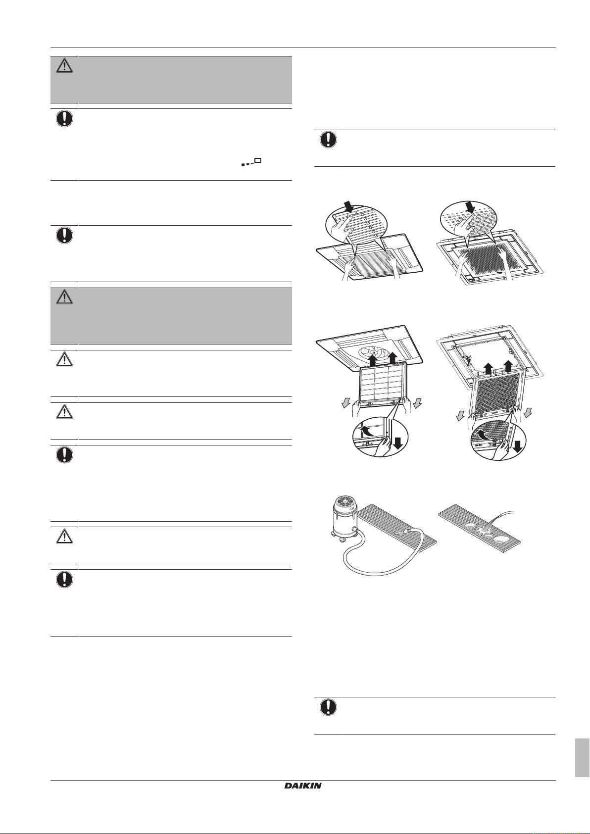
1 Open the suction grille.
BYFQ60B BYFQ60C
2 Remove the air filter.
BYFQ60B BYFQ60C
CAUTION
Do not insert fingers, rods or other objects into the air inlet
or outlet. Do not remove the fan guard. When the fan is
rotating at high speed, it will cause injury.
CAUTION
After a long use, check the unit stand and fitting for
damage. If damaged, the unit may fall and result in injury.
NOTICE
Do not wipe the controller operation panel with benzine,
thinner, chemical dust cloth, etc. The panel may get
discoloured or the coating peeled off. If it is heavily dirty,
soak a cloth in water-diluted neutral detergent, squeeze it
well and wipe the panel clean. Wipe it with another dry
cloth.
CAUTION
Before accessing terminal devices, make sure to interrupt
all power supply.
NOTICE
When cleaning the heat exchanger, make sure to remove
the switch box, fan motor, drain pump and float switch.
Water or detergent might deteriorate the insulation of
electronic components and result in burnout of these
components.
13.1 Cleaning the air filter, suction grille, air outlet and outside panels
13.1.1 To clean the air filter
When to clean the air filter:
▪ Rule of thumb: Clean every 6 months. If the air in the room is
extremely contaminated, increase the cleaning frequency.
3 Clean the air filter. Use a vacuum cleaner or wash with water. If
the air filter is very dirty, use a soft brush and neutral detergent.
4 Dry the air filter in the shadow.
5 Reattach the air filter and close the suction grille (steps 2 and 1
in reverse order).
6 Turn ON the power.
7 Press the FILTER SIGN RESET button.
Result: The TIME TO CLEAN AIR FILTER notification
disappears from the user interface.
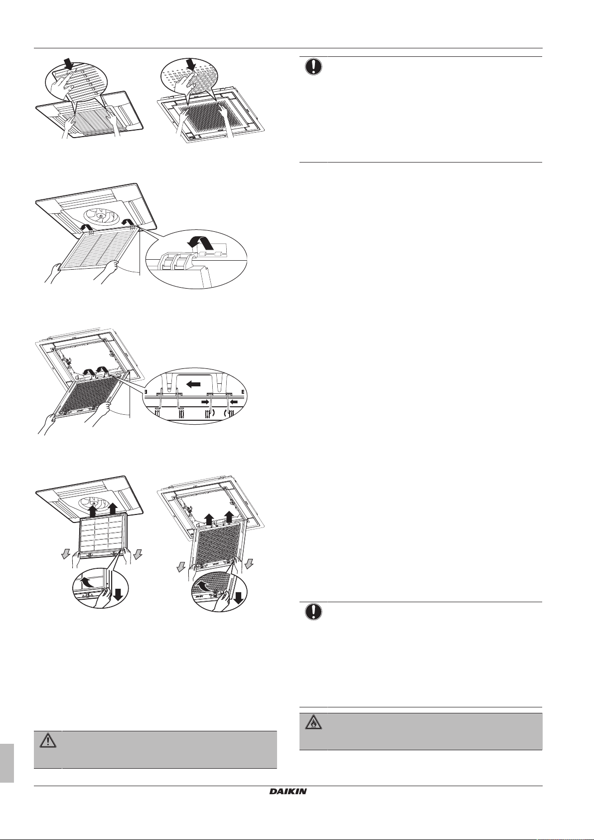
13.1.2 To clean the suction grille
NOTICE
Do NOT use water of 50°C or higher. Possible
consequence: Discoloration and deformation.
1 Open the suction grille.
FFA25~60A2VEB
Split system air conditioners
4P456960-1 – 2017.03
BYFQ60B BYFQ60C
Installation and operation manual
17
13 Maintenance and service
1
45°
1
90°
1
3
3
2
3
3
1
2
2 Remove the suction grille.
BYFQ60B
BYFQ60C
NOTICE
▪ Do NOT use gasoline, benzene, thinner polishing
powder or liquid insecticide. Possible consequence:
Discoloration and deformation.
▪ Do NOT use water or air of 50°C or higher. Possible
consequence: Discoloration and deformation.
▪ Do NOT scrub firmly when washing the blade with
water. Possible consequence: The surface sealing
peels off.
Clean with a soft cloth. If it is difficult to remove stains, use water or
neutral detergent.
13.2 Maintenance after a long stop period
E.g., at the beginning of the season.
▪ Check and remove everything that might be blocking inlet and
outlet vents of indoor units and outdoor units.
▪ Clean air filters and casings of indoor units (see "13.1.1 To clean
the air filter" on page 17 and "13.1.3 To clean the air outlet and
outside panels"on page18).
▪ Turn on the power at least 6 hours before operating the unit in
order to ensure smoother operation. As soon as the power is
turned on, the user interface display appears.
3 Remove the air filter.
BYFQ60B BYFQ60C
4 Clean the suction grille. Wash with a soft bristle brush and
water or neutral detergent. If the suction grille is very dirty, use
a typical kitchen cleaner, leave it on for 10 min, then wash it
with water.
5 Reattach the air filter (step 3 in reverse order).
6 Reattach the suction grille and close it. (step 2 and 1 in reverse
order)
13.3 Maintenance before a long stop period
E.g., at the end of the season.
▪ Let the indoor units run in fan only operation for about half a day in
order to dry the interior of the units. Refer to "12.2.2 About
cooling, heating, fan only, and automatic operation"on page 16
for details on fan only operation.
▪ Turn off the power. The user interface display disappears.
▪ Clean air filters and casings of indoor units (see "13.1.1 To clean
the air filter" on page 17 and "13.1.3 To clean the air outlet and
outside panels"on page18).
13.4 About the refrigerant
This product contains fluorinated greenhouse gases. Do NOT vent
gases into the atmosphere.
Refrigerant type: R32
Global warming potential (GWP) value: 675
Refrigerant type: R410A
Global warming potential (GWP) value: 2087.5
NOTICE
In Europe, the greenhouse gas emissions of the total
refrigerant charge in the system (expressed as tonnes
CO2-equivalent) is used to determine the maintenance
intervals. Follow the applicable legislation.
Formula to calculate the greenhouse gas emissions:
GWP value of the refrigerant × Total refrigerant charge [in
kg] / 1000
Please contact your installer for more information.
13.1.3 To clean the air outlet and outside panels
WARNING
Do NOT let the indoor unit get wet. Possible
consequence: Electric shock or fire.
Installation and operation manual
18
WARNING: FLAMMABLE MATERIAL
The R32 refrigerant (if applicable) in this unit is mildly
flammable.
(a)
(a) Refer to the outdoor unit specifications for the type of
refrigerant to be used.
FFA25~60A2VEB
Split system air conditioners
4P456960-1 – 2017.03

13 Maintenance and service
WARNING
▪ Do NOT pierce or burn refrigerant cycle parts.
▪ Do NOT use cleaning materials or means to accelerate
the defrosting process other than those recommended
by the manufacturer.
▪ Be aware that the refrigerant inside the system is
odourless.
WARNING
R410A is a non-combustible refrigerant, and R32 is a
mildly flammable refrigerant; they normally don’t leak. If the
refrigerant leaks in the room and comes in contact with fire
from a burner, a heater, or a cooker, this may result in a
fire (in case of R32), or the formation of a harmful gas.
Turn off any combustible heating devices, ventilate the
room, and contact the dealer from where you purchased
the unit.
Do not use the unit until a service person confirms that the
part from which the refrigerant leaked has been repaired.
13.5 After-sales service and warranty
13.5.1 Warranty period
▪ This product includes a warranty card that was filled in by the
dealer at the time of installation. The completed card has to be
checked by the customer and stored carefully.
▪ If repairs to the product are necessary within the warranty period,
contact your dealer and keep the warranty card at hand.
13.5.2 Recommended maintenance and inspection
Since dust collects when using the unit for several years,
performance of the unit will deteriorate to some extent. As taking
apart and cleaning interiors of units requires technical expertise and
in order to ensure the best possible maintenance of your units, we
recommend to enter into a maintenance and inspection contract on
top of normal maintenance activities. Our network of dealers has
access to a permanent stock of essential components in order to
keep your unit in operation as long as possible. Contact your dealer
for more information.
When asking your dealer for an intervention, always state:
▪ The complete model name of the unit.
▪ The manufacturing number (stated on the nameplate of the unit).
▪ The installation date.
▪ The symptoms or malfunction, and details of the defect.
WARNING
▪ Do not modify, disassemble, remove, reinstall or repair
the unit yourself as incorrect dismantling or installation
may cause an electric shock or fire. Contact your
dealer.
▪ In case of accidental refrigerant leaks, make sure there
are no naked flames. The refrigerant itself is entirely
safe and non-toxic. R410A is a non-combustible
refrigerant, and R32 is a mildly flammable refrigerant,
but they will generate a toxic gas when they
accidentally leak into a room where combustible air
from fan heaters, gas cookers, etc. is present. Always
have qualified service personnel confirm that the point
of leakage has been repaired or corrected before
resuming operation.
13.5.3 Recommended maintenance and inspection cycles
Be aware that the mentioned maintenance and replacement cycles
do not relate to the warranty period of the components.
Component Inspection
cycle
Electric motor 1 year 20,000 hours
PCB 25,000 hours
Heat exchanger 5 years
Sensor (thermistor, etc.) 5 years
User interface and switches 25,000 hours
Drain pan 8 years
Expansion valve 20,000 hours
Solenoid valve 20,000 hours
The table assumes the following conditions of use:
▪ Normal use without frequent starting and stopping of the unit.
Depending on the model, we recommend not starting and
stopping the machine more than 6 times/hour.
▪ Operation of the unit is assumed to be 10 hours/day and
2,500hours/year.
NOTICE
▪ The table indicates main components. Refer to your
maintenance and inspection contract for more details.
▪ The table indicates recommended intervals of
maintenance cycles. However, in order to keep the unit
operational as long as possible, maintenance work may
be required sooner. Recommended intervals can be
used for appropriate maintenance design in terms of
budgeting maintenance and inspection fees.
Depending on the content of the maintenance and
inspection contract, inspection and maintenance cycles
may in reality be shorter than listed.
Maintenance cycle
(replacements and/or
repairs)
13.5.4 Shortened maintenance and replacement cycles
Shortening of "maintenance cycle" and "replacement cycle" needs to
be considered in following situations:
The unit is used in locations where:
▪ Heat and humidity fluctuate out of the ordinary.
▪ Power fluctuation is high (voltage, frequency, wave distortion, etc.)
(the unit cannot be used if power fluctuation is outside the
allowable range).
▪ Bumps and vibrations are frequent.
▪ Dust, salt, harmful gas or oil mist such as sulphurous acid and
hydrogen sulfide may be present in the air.
▪ The machine is started and stopped frequently or operation time is
long (sites with 24 hour air-conditioning).
Recommended replacement cycle of wear parts
Component Inspection
cycle
Air filter 1 year 5 years
High efficiency filter 1 year
Fuse 10 years
Pressure containing parts In case of corrosion,
Maintenance cycle
(replacements and/or
repairs)
contact your local dealer.
FFA25~60A2VEB
Split system air conditioners
4P456960-1 – 2017.03
Installation and operation manual
19

14 Troubleshooting
NOTICE
▪ The table indicates main components. Refer to your
maintenance and inspection contract for more details.
▪ The table indicates recommended intervals of
replacement cycles. However, in order to keep the unit
operational as long as possible, maintenance work may
be required sooner. Recommended intervals can be
used for appropriate maintenance design in terms of
budgeting maintenance and inspection fees. Contact
your dealer for details.
INFORMATION
Damage due to taking apart or cleaning interiors of units by
anyone other than our authorised dealers may not be
included in the warranty.
14 Troubleshooting
If one of the following malfunctions occur, take the measures shown
below and contact your dealer.
WARNING
Stop operation and shut off the power if anything
unusual occurs (burning smells etc.).
Leaving the unit running under such circumstances may
cause breakage, electric shock or fire. Contact your dealer.
The system must be repaired by a qualified service person:
Malfunction Measure
If a safety device such as a fuse, a
breaker or an earth leakage breaker
frequently actuates or the ON/OFF
switch does not properly work.
If water leaks from the unit. Stop the operation.
The operation switch does not work
well.
If the user interface display indicates the
unit number, the operation lamp flashes
and the malfunction code appears.
If the system does not properly operate except for the above
mentioned cases and none of the above mentioned malfunctions is
evident, investigate the system according to the following
procedures.
Malfunction Measure
If the system does not
operate at all.
▪ Check if there is no power failure. Wait
until power is restored. If power failure
occurs during operation, the system
automatically restarts immediately after
power is restored.
▪ Check if no fuse has blown or breaker is
activated. Change the fuse or reset the
breaker if necessary.
Turn off the main power
switch.
Turn off the power.
Notify your installer and
report the malfunction
code.
Malfunction Measure
The system operates
but cooling or heating
is insufficient.
If after checking all above items, it is impossible to fix the problem
yourself, contact your installer and state the symptoms, the complete
model name of the unit (with manufacturing number if possible) and
the installation date (possibly listed on the warranty card).
▪ Check if air inlet or outlet of outdoor or
indoor unit is not blocked by obstacles.
Remove any obstacles and make sure
the air can flow freely.
▪ Check if the air filter is not clogged (see
"13.1.1 To clean the air filter" on
page17).
▪ Check the temperature setting.
▪ Check the fan speed setting on your user
interface.
▪ Check for open doors or windows. Close
doors and windows to prevent wind from
coming in.
▪ Check if there are too many occupants in
the room during cooling operation. Check
if the heat source of the room is
excessive.
▪ Check if direct sunlight enters the room.
Use curtains or blinds.
▪ Check if the air flow angle is proper.
14.1 Symptoms that are NOT system malfunctions
The following symptoms are NOT system malfunctions:
14.1.1 Symptom: The system does not operate
▪ The air conditioner does not start immediately after the ON/OFF
button on the user interface is pressed. If the operation lamp
lights, the system is in normal condition. To prevent overloading of
the compressor motor, the air conditioner starts 5 minutes after it
is turned ON again in case it was turned OFF just before. The
same starting delay occurs after the operation mode selector
button was used.
▪ If "Under Centralized Control" is displayed on the user interface,
pressing the operation button causes the display to blink for a few
seconds. The blinking display indicates that the user interface
cannot be used.
▪ The system does not start immediately after the power supply is
turned on. Wait one minute until the micro computer is prepared
for operation.
14.1.2 Symptom: The fan strength does not correspond to the setting
The fan speed does not change even if the fan speed adjustment
button in pressed. During heating operation, when the room
temperature reaches the set temperature, the outdoor unit goes off
and the indoor unit changes to whisper fan speed. This is to prevent
cold air blowing directly on occupants of the room. The fan speed
will not change if the button is pressed.
Installation and operation manual
20
14.1.3 Symptom: The fan direction does not correspond to the setting
The fan direction does not correspond with the user interface
display. The fan direction does not swing. This is because the unit is
being controlled by the micro computer.
FFA25~60A2VEB
Split system air conditioners
4P456960-1 – 2017.03

15 Relocation
14.1.4 Symptom: White mist comes out of a unit (Indoor unit)
▪ When humidity is high during cooling operation. If the interior of an
indoor unit is extremely contaminated, the temperature distribution
inside a room becomes uneven. It is necessary to clean the
interior of the indoor unit. Ask your dealer for details on cleaning
the unit. This operation requires a qualified service person.
▪ Immediately after the cooling operation stops and if the room
temperature and humidity are low. This is because warm
refrigerant gas flows back into the indoor unit and generates
steam.
14.1.5 Symptom: White mist comes out of a unit (Indoor unit, outdoor unit)
When the system is changed over to heating operation after defrost
operation. Moisture generated by defrost becomes steam and is
exhausted.
14.1.6 Symptom: The user interface display reads "U4" or "U5" and stops, but then restarts after a few minutes
This is because the user interface is intercepting noise from electric
appliances other than the air conditioner. The noise prevents
communication between the units, causing them to stop. Operation
automatically restarts when the noise ceases.
14.1.7 Symptom: Noise of air conditioners (Indoor unit)
▪ A "zeen" sound is heard immediately after the power supply is
turned on. The electronic expansion valve inside an indoor unit
starts working and makes the noise. Its volume will reduce in
about one minute.
▪ A continuous low "shah" sound is heard when the system is in
cooling operation or at a stop. When the drain pump is in
operation, this noise is heard.
▪ A "pishi-pishi" squeaking sound is heard when the system stops
after heating operation. Expansion and contraction of plastic parts
caused by temperature change make this noise.
14.1.12 Symptom: The outdoor unit fan does not spin
During operation. The speed of the fan is controlled in order to
optimise product operation.
14.1.13 Symptom: The display shows "88"
This is the case immediately after the main power supply switch is
turned on and means that the user interface is in normal condition.
This continues for 1minute.
14.1.14 Symptom: The compressor in the outdoor unit does not stop after a short heating operation
This is to prevent refrigerant from remaining in the compressor. The
unit will stop after 5 to 10 minutes.
15 Relocation
Contact your dealer for removing and reinstalling the total unit.
Moving units requires technical expertise.
16 Disposal
This unit uses hydrofluorocarbon. Contact your dealer when
discarding this unit.
NOTICE
Do not try to dismantle the system yourself: the dismantling
of the system, treatment of the refrigerant, oil and other
parts must comply with applicable legislation. Units must
be treated at a specialized treatment facility for reuse,
recycling and recovery.
14.1.8 Symptom: Noise of air conditioners (Indoor unit, outdoor unit)
▪ A continuous low hissing sound is heard when the system is in
cooling or defrost operation. This is the sound of refrigerant gas
flowing through both indoor and outdoor units.
▪ A hissing sound which is heard at the start or immediately after
stopping operation or defrost operation. This is the noise of
refrigerant caused by flow stop or flow change.
14.1.9 Symptom: Noise of air conditioners (Outdoor unit)
When the tone of operating noise changes. This noise is caused by
the change of frequency.
14.1.10 Symptom: Dust comes out of the unit
When the unit is used for the first time in a long time. This is
because dust has gotten into the unit.
14.1.11 Symptom: The units can give off odours
The unit can absorb the smell of rooms, furniture, cigarettes, etc.,
and then emit it again.
FFA25~60A2VEB
Split system air conditioners
4P456960-1 – 2017.03
Installation and operation manual
21


4P456960-1 2017.03
Copyright 2017 Daikin
 Loading...