

Daikin FCQ71KVLT, FCQ100KVLT, FCQ140KVLT, FCQ125KVLT Removal Manual
REMOVAL
PROCEDURE
SERVICE MANUAL
Indoor Unit
Inverter
Pair Type
3/4/5/6 HP Class
Si281312E

Service Manual
Removal Procedure
Outdoor Unit
Applicable Models
zHeat Pump
FCQ71KVLT
FCQ100KVLT
FCQ125KVLT
FCQ140KVLT

Si281312E
Removal Procedure 1
Table of Contents
1. Procedure to Remove Air Filter and Suction Grille .................................2
2. Procedure to Remove Decoration Panel.................................................3
3. Procedure to Remove Horizontal Blade..................................................4
4. Procedure to Remove Swing Motor ........................................................6
5. Procedure to Remove Switch Box ..........................................................7
6. Procedure to Remove PCB.....................................................................8
7. Procedure to Remove Bell Mouth and Drain Pan ...................................9
8. Procedure to Remove Fan Motor..........................................................10
9. Procedure to Remove Drain Pump, Float Switch..................................11
10.Procedure to Remove Humidity Thermistor and
Air Temperature Thermistor..................................................................12
11.Procedure to Remove Heat Exchanger Temperature Thermistor.........13
Procedure to Remove Air Filter and Suction Grille Si281312E
2 Removal Procedure
1. Procedure to Remove Air Filter and Suction Grille
Procedure Warning Be sure to wait for 10 minutes or more after turning off all power
supplies before disassembling work.
Step
Procedure Points
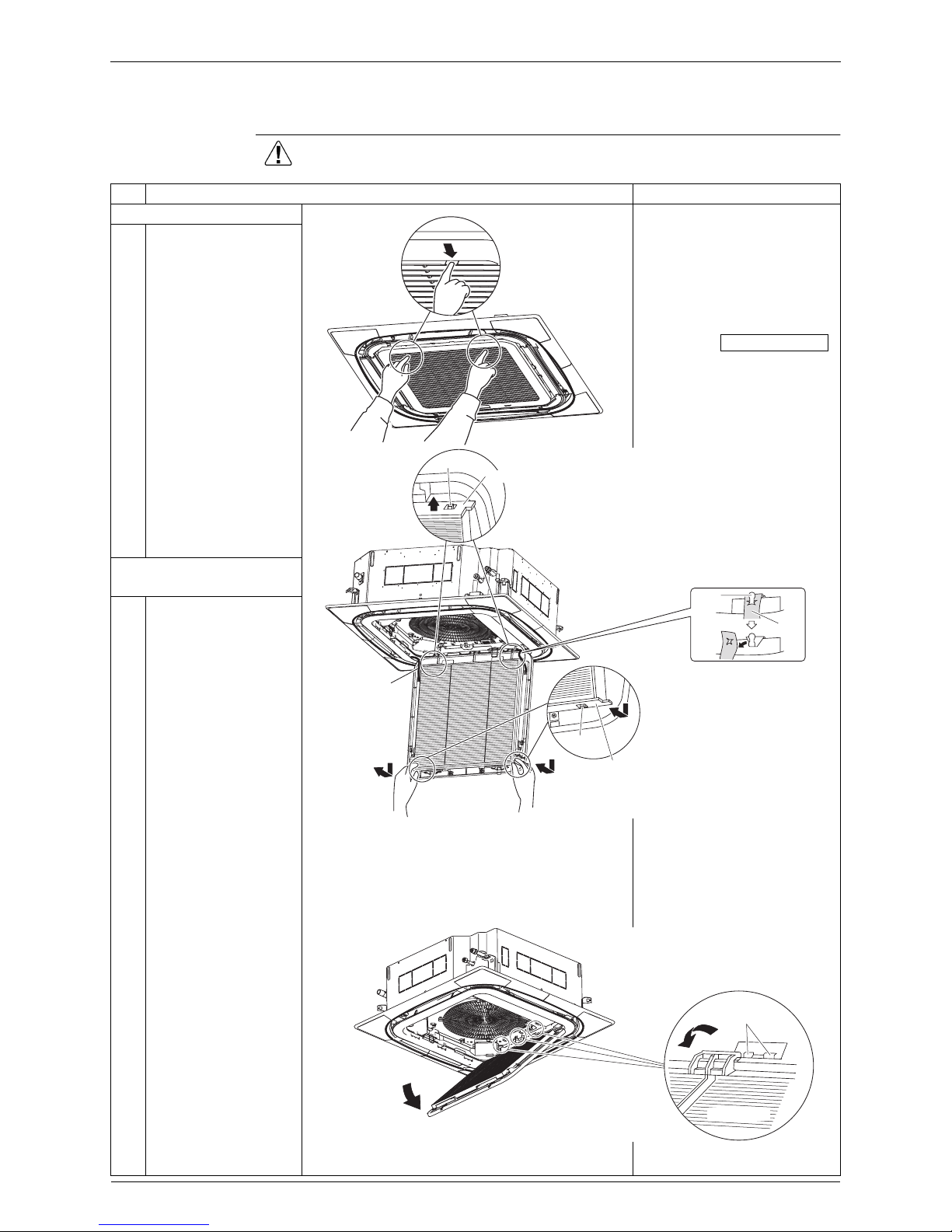
1. Removing the air filter
Clean stains off the air filter
with a vacuum cleaner or
wash them off with water.
(Do not use hot water of
50°C or more temperature
for this purpose.)
After cleaning the air filter,
press the
button on the remote
controller.
(The message “Clean Filter”
will disappear from the
remote controller display.)
1
Press the 2 buttons
simultaneously and pull
the suction grille down
slowly.
2
Pull down the bottom
part of the air filter
once, and then
disengage the hole (2
places) for latch from
the protrusion
respectively.
3
Hold up the air filter,
and then disengage the
hole (2 places) for latch
from the protrusion
located at the top end
respectively.
2. Removing the suction
grille
1
Disengage the strings
(2 places) located at the
top of the suction grille
from the panel.
2
Open the suction grille
to an angle of 45
degrees, and then hold
it up to unlatch the
latches located in 3
places.
Clean stains off the suction
grill using a soft brush with
water or mild detergent.
(Do not use hot water of
50°C or more temperature
for this purpose.)
Protrusion
Top of air filter
String
Protrusion
Bottom of
air filter
Bracket
String
Latches located in 3 places
Panel latches
Suction grille
Filter Sign Reset
Si281312E Procedure to Remove Decoration Panel
Removal Procedure 3
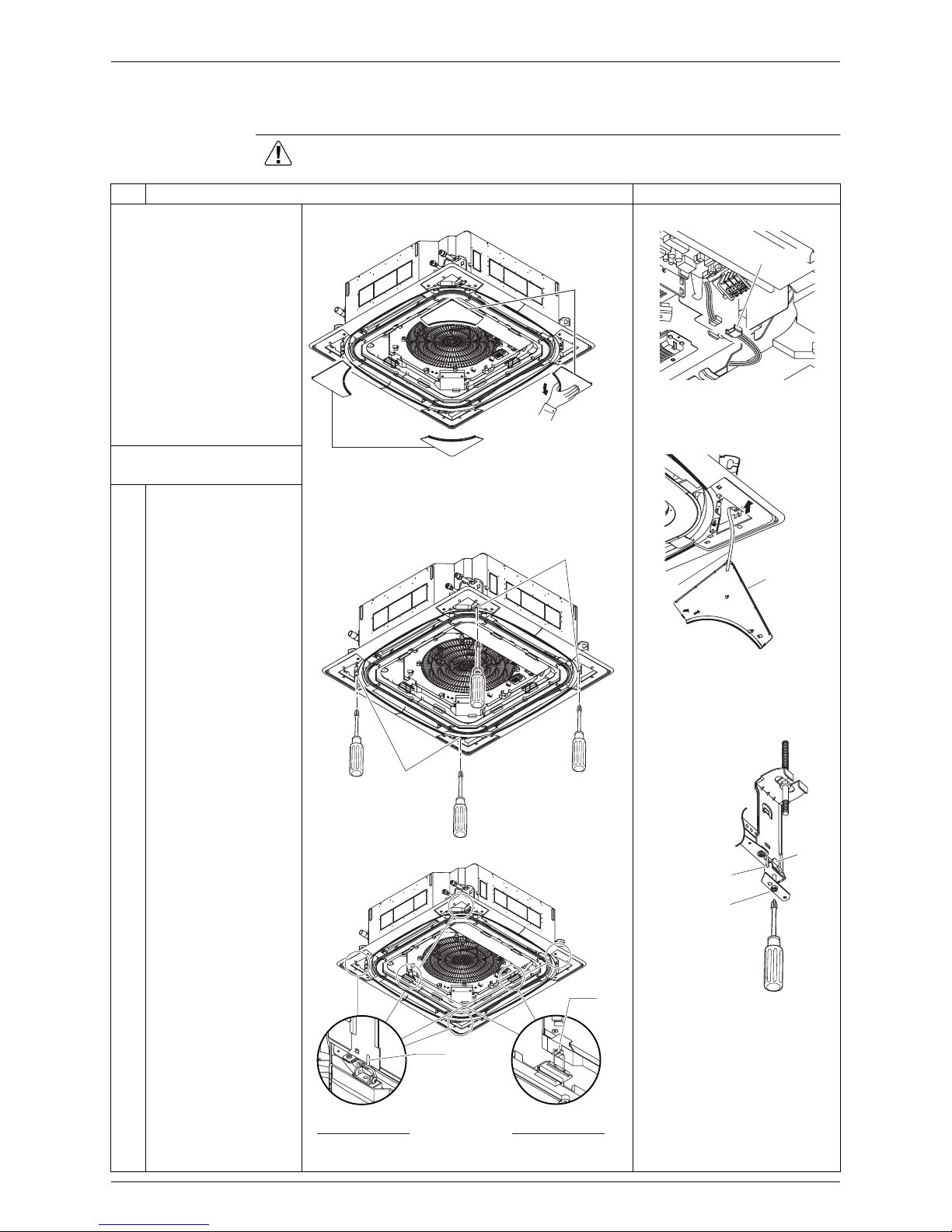
2. Procedure to Remove Decoration Panel
Procedure Warning Be sure to wait for 10 minutes or more after turning off all power
supplies before disassembling work.
Step
Procedure Points
Removing the suction
grille according to
procedure for removing
the suction grille.
Relay connector
Corner cover string
Screw fixing the decoration
panel
According to the
procedure for the removal
of PCB, remove the lid
from the switch box and
disconnect the relay
connector for the swing
motor.
1. Removing the decoration
panel
1
Pull down the corner
covers on the inner side
(i.e., the suction grille
side) to remove them.
2
Remove the corner
cover strings.
3
Unfasten the 4 screws
that fix the decoration
panel to the extent that
the panel is loosely
fixed.
4
Unlatch the 4 outer
latches (A).
(At this time, make sure
the 2 inner latches (B)
are latched.)
5
While holding the
decoration panel with
both hands, unlatch the
2 inner latches (B), and
then remove the
decoration panel.
Corner cover
Corner cover
Mounting screws
Mounting
screws
Hook
Outer latch (A)
(located in 4 places)
Hook
Inner latch (B)
(located in 2 places)
Relay connector
String
Corner cover
Latch
Mounting screws
Hook

Procedure to Remove Horizontal Blade Si281312E
4 Removal Procedure
3. Procedure to Remove Horizontal Blade
Procedure Warning Be sure to wait for 10 minutes or more after turning off all power
supplies before disassembling work.
Step
Procedure Points
Removing the decoration
panel according to
procedure for removing
the decoration panel.
1. Remove the inner frame
from the decoration panel
1
Unscrew the 4 screws
from the back of the
decoration panel.
2
Remove the 4 seal
parts (A) from the back
of the decoration panel.
3
Unscrew the 4 screws
from the front of the
decoration panel.
4
Pull out the inner frame
straight from the
decoration panel.
2. Remove parts related to
heat insulation
1
Remove heat insulation
from the 4 inner frames.
2
Remove heat insulation
from the 4 corners.
3
Remove a total of 8
bearing mounting
plates by unscrewing
1
screw, respectively.
Screw on the back side
(located in 4 places)
Seal part (A)
(located in 4 places)
Inner frame of
decoration panel
Screw on the front side
(located in 4 places)
Heat insulation of corner
(located in 4 places)
Bearing mounting plates
(located in 8 places)
Heat insulation of inner frame
(located in 4 places)
 Loading...