


INSTALLATION AND
OPERATION MANUAL
Packaged air-cooled water chillers
EUWAC5FBZW1
EUWAC8FBZW1
EUWAC10FBZW1
1
R
Q
D
M
N
15
G
F
E
H
12
O
P
J
K
I
L
L
27
B
A
C
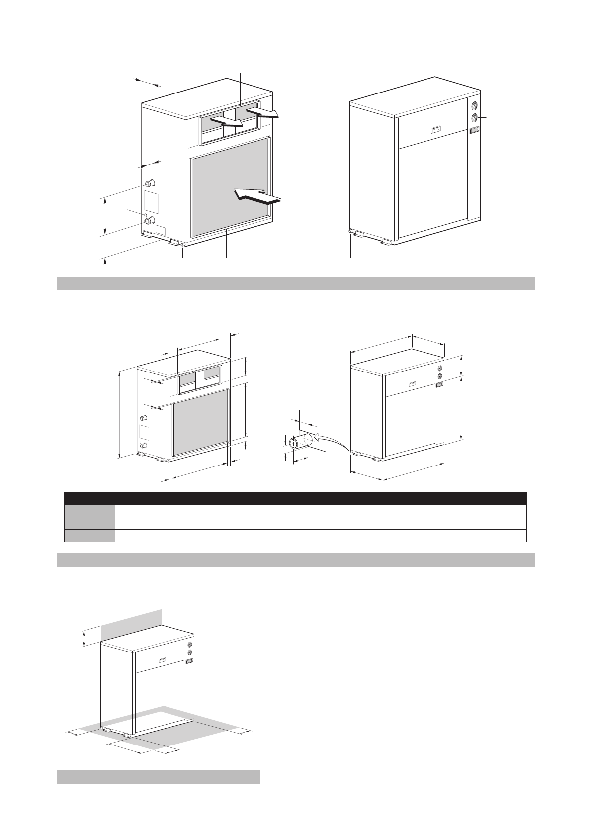
A B C D E F G H I J K L M N O P Q R
EUWAC5FZ (mm) 243 311 243 1345 343 125 765 71 58 629 108 25 796 605 735 578 600 795
133
11
1
9
8
6
52
3
5
466
4
110
10712
7 2
1
2
EUWAC8FZ (mm) 163 800 162 1290 267 98 815 71 60 951 111 25 1125 605 288 975 600 1122
EUWAC10FZ (mm) 170 936 169 1395 292 127 857 71 60 1101 111 25 1275 605 286 1083 600 1272
2
3
500
800
200
250
3
200
CE - ATITIKTIES-DEKLARACIJA
CE - ATBILSTĪBAS-DEKLARĀCIJA
CE - VYHLÁSENIE-ZHODY
CE - UYUMLULUK-BİLDİRİSİ
CE - IZJAVA O SKLADNOSTI
CE - VASTAVUSDEKLARATSIOON
CE - ДЕКЛАРАЦИЯ-ЗА-СЪОТВЕТСТВИЕ
19 Direktive z vsemi spremembami.
20 Direktiivid koos muudatustega.
21 Директиви, с техните изменения.
22 Direktyvose su papildymais.
23 Direktīvās un to papildinājumos.
24 Smernice, v platnom znení.
25 Değiştirilmiş halleriyle Yönetmelikler.
Direktiivejä, sellaisina kuin ne ovat muutettuina.
10 Direktiver, med senere ændringer.
11 Direktiv, med företagna ändringar.
irányelv(ek) és módosításaik rendelkezéseit.
12 Direktiver, med foretatte endringer.
13
14 v platném znění.
15 Smjernice, kako je izmijenjeno.
16
17 z późniejszymi poprawkami.
18 Directivelor, cu amendamentele respective.
положително от <B> съгласно
<A> DAIKIN.TCF.003E1/04-2010
<B> KEMA (NB0344)
<C> 59276-KRQ/ECM95-4230
Daikin Europe N.V. je pooblaščen za sestavo datoteke s tehnično mapo.
Daikin Europe N.V. on volitatud koostama tehnilist dokumentatsiooni.
Daikin Europe N.V. е оторизирана да състави Акта за техническа конструкция.
Daikin Europe N.V. yra įgaliota sudaryti šį techninės konstrukcijos failą.
Daikin Europe N.V. ir autorizēts sastādīt tehnisko dokumentāciju.
Spoločnosť Daikin Europe N.V. je oprávnená vytvoriť súbor technickej konštrukcie.
**
21
**
22
**
23
**
24
Daikin Europe N.V. Teknik Yapı Dosyasını derlemeye yetkilidir.
**
25
**
**
20
19
súlade s osvedčením <C>.
<A>‘da belirtildiği gibi ve <C> Sertifikasına
göre <B> tarafından olumlu olarak
vērtējumam saskaņā ar sertifikātu <C>.
pagal Sertifikatą <C>.
Cертификата <C>.
değerlendirildiği gibi.
deklaruje na własną i wyłączną odpowiedzialność, że modele klimatyzatorów, których dotyczy niniejsza deklaracja:
declară pe proprie răspundere că aparatele de aer condiţionat la care se referă această declaraţie:
z vso odgovornostjo izjavlja, da so modeli klimatskih naprav, na katere se izjava nanaša:
kinnitab oma täielikul vastutusel, et käesoleva deklaratsiooni alla kuuluvad kliimaseadmete mudelid:
m
r
o
x
18
19
20
17
CE - IZJAVA-O-USKLAĐENOSTI
CE - MEGFELELŐSÉGI-NYILATKOZAT
CE - DEKLARACJA-ZGODNOŚCI
CE - DECLARAŢIE-DE-CONFORMITATE
CE - ERKLÆRING OM-SAMSVAR
CE - ILMOITUS-YHDENMUKAISUUDESTA
CE - PROHLÁŠENÍ-O-SHODĚ
заявляет, исключительно под свою ответственность, что модели кондиционеров воздуха, к которым относится настоящее заявление:
erklærer under eneansvar, at klimaanlægmodellerne, som denne deklaration vedrører:
deklarerar i egenskap av huvudansvarig, att luftkonditioneringsmodellerna som berörs av denna deklaration innebär att:
erklærer et fullstendig ansvar for at de luftkondisjoneringsmodeller som berøres av denne deklarasjon innebærer at:
u
q
s
n
11
12
09
10
декларира на своя отговорност, че моделите климатична инсталация, за които се отнася тази декларация:
b
21
tamamen kendi sorumluluğunda olmak üzere bu bildirinin ilgili olduğu klima modellerinin aşağıdaki gibi olduğunu beyan eder:
visiška savo atsakomybe skelbia, kad oro kondicionavimo prietaisų modeliai, kuriems yra taikoma ši deklaracija:
ar pilnu atbildību apliecina, ka tālāk uzskaitīto modeĮu gaisa kondicionētāji, uz kuriem attiecas šī deklarācija:
vyhlasuje na vlastnú zodpovednosť, že tieto klimatizačné modely, na ktoré sa vzťahuje toto vyhlásenie:
w
t
v
k
22
23
24
25
instrukcjami:
conformitate cu instrucţiunile noastre
инструкции:
16 megfelelnek az alábbi szabvány(ok)nak vagy egyéb irányadó dokumentum(ok)nak, ha azokat előírás szerint használják:
17 spełniają wymogi następujących norm i innych dokumentów normalizacyjnych, pod warunkiem że używane są zgodnie z naszymi
18 sunt în conformitate cu următorul (următoarele) standard(e) sau alt(e) document(e) normativ(e), cu condiţia ca acestea să fie utilizate în
19 skladni z naslednjimi standardi in drugimi normativi, pod pogojem, da se uporabljajo v skladu z našimi navodili:
20 on vastavuses järgmis(t)e standardi(te)ga või teiste normatiivsete dokumentidega, kui neid kasutatakse vastavalt meie juhenditele:
21 съответстват на следните стандарти или други нормативни документи, при условие, че се използват съгласно нашите
s našim návodom:
22 atitinka žemiau nurodytus standartus ir (arba) kitus norminius dokumentus su sąlyga, kad yra naudojami pagal mūsų nurodymus:
23 tad, ja lietoti atbilstoši ražotāja norādījumiem, atbilst sekojošiem standartiem un citiem normatīviem dokumentiem:
24 sú v zhode s nasledovnou(ými) normou(ami) alebo iným(i) normatívnym(i) dokumentom(ami), za predpokladu, že sa používajú v súlade
25 ürünün, talimatlarımıza göre kullanılması koşuluyla aşağıdaki standartlar ve norm belirten belgelerle uyumludur:
01 Directives, as amended.
02 Direktiven, gemäß Änderung.
03 Directives, telles que modifiées.
04 Richtlijnen, zoals geamendeerd.
05 Directivas, según lo enmendado.
06 Direttive, come da modifica.
*
**
21 Забележка * както е изложено в <A> и оценено
07 √‰ËÁÈÒv, fiˆ˜ ¤¯Ô˘Ó ÙÚÔÔÔÈËı›.
08 Directivas, conforme alteração em.
09 Директив со всеми поправками.
a(z) <C> tanúsítvány szerint.
16 Megjegyzés * a(z) <A> alapján, a(z) <B> igazolta a megfelelést,
Machinery 2006/42/EC
Electromagnetic Compatibility 2004/108/EC
Certifikatet <C>.
ilmoittaa yksinomaan omalla vastuullaan, että tämän ilmoituksen tarkoittamat ilmastointilaitteiden mallit:
prohlašuje ve své plné odpovědnosti, že modely klimatizace, k nimž se toto prohlášení vztahuje:
izjavljuje pod isključivo vlastitom odgovornošću da su modeli klima uređaja na koje se ova izjava odnosi:
teljes felelőssége tudatában kijelenti, hogy a klímaberendezés modellek, melyekre e nyilatkozat vonatkozik:
j
c
y
h
13
14
15
16
acordo com as nossas instruções:
инструкциям:
instrukser:
förutsättning att användning sker i överensstämmelse med våra instruktioner:
disse brukes i henhold til våre instrukser:
08 estão em conformidade com a(s) seguinte(s) norma(s) ou outro(s) documento(s) nor mativo(s), desde que estes sejam utilizados de
09 соответствуют следующим стандартам или другим нормативным документам, при условии их использования согласно нашим
10 overholder følgende standard(er) eller andet/andre retningsgivende dokument(er), forudsat at disse anvendes i henhold til vore
11 respektive utrustning är utförd i överensstämmelse med och följer följande standard(er) eller andra normgivande dokument, under
mukaisesti:
12 respektive utstyr er i overensstemmelse med følgende standard(er) eller andre normgivende dokument(er), under forutssetning av at
13 vastaavat seuraavien standardien ja muiden ohjeellisten dokumenttien vaatimuksia edellyttäen, että niitä käytetään ohjeidemme
14 za předpokladu, že jsou využívány v souladu s našimi pokyny, odpovídají následujícím normám nebo normativním dokumentům:
15 u skladu sa slijedećim standardom(ima) ili drugim normativnim dokumentom(ima), uz uvjet da se oni koriste u skladu s našim uputama:
11 Information * enligt <A> och godkänts av <B> enligt
24 Poznámka * ako bolo uvedené v <A> a pozitívne zistené <B> v
23 Piezīmes * kā norādīts <A> un atbilstoši <B> pozitīvajam
22 Pastaba * kaip nustatyta <A> ir kaip teigiamai nuspręsta <B>
<B> i Świadectwem <C>.
de <B> în conformitate cu Certificatul <C>.
skladu s certifikatom <C>.
17 Uwaga * zgodnie z dokumentacją <A>, pozytywną opinią
18 Notă * aşa cum este stabilit în <A> şi apreciat pozitiv
19 Opomba * kot je določeno v <A> in odobreno s strani <B> v
20 Märkus * nagu on näidatud dokumendis <A> ja heaks
bedømmelse av <B> ifølge Sertifikat <C>.
hyväksynyt Sertifikaatin <C> mukaisesti.
souladu s osvědčením <C>.
12 Merk * som det fremkommer i <A> og gjennom positiv
13 Huom * jotka on esitetty asiakirjassa <A> ja jotka <B> on
14 Poznámka * jak bylo uvedeno v <A> a pozitivně zjištěno <B> v
15 Napomena * kako je izloženo u <A> i pozitivno ocijenjeno od
*
Not
25
kiidetud <B> järgi vastavalt sertifikaadile <C>.
strane <B> prema Certifikatu <C>.
Daikin Europe N.V. on valtuutettu laatimaan Teknisen asiakirjan.
Společnost Daikin Europe N.V. má oprávnění ke kompilaci souboru technické konstrukce.
Daikin Europe N.V. je ovlašten za izradu Datoteke o tehničkoj konstrukciji.
A Daikin Europe N.V. jogosult a műszaki konstrukciós dokumentáció összeállítására.
Daikin Europe N.V. ma upoważnienie do zbierania i opracowywania dokumentacji konstrukcyjnej.
**
13
Daikin Europe N.V. este autorizat să compileze Dosarul tehnic de construcţie.
**
**
**
**
**
14
15
16
17
18
Jean-Pierre Beuselinck
General Manager
Ostend, 1st of July 2010
CE - FÖRSÄKRAN-OM-ÖVERENSTÄMMELSE
CE - DECLARAÇÃO-DE-CONFORMIDADE
СЕ - ЗАЯВЛЕНИЕ-О-СООТВЕТСТВИИ
CE - OPFYLDELSESERKLÆRING
CE - DECLARACION-DE-CONFORMIDAD
CE - DICHIARAZIONE-DI-CONFORMITA
CE - ¢H§ø™H ™YMMOPºø™H™
declares under its sole responsibility that the air conditioning models to which this declaration relates:
CE - DECLARATION-OF-CONFORMITY
CE - KONFORMITÄTSERKLÄRUNG
a
CE - DECLARATION-DE-CONFORMITE
CE - CONFORMITEITSVERKLARING
Daikin Europe N.V.
01
declaración:
referencia la
erklärt auf seine alleinige Verantwortung daß die Modelle der Klimageräte für die diese Erklärung bestimmt ist:
déclare sous sa seule responsabilité que les appareils d'air conditionné visés par la présente déclaration:
verklaart hierbij op eigen exclusieve verantwoordelijkheid dat de airconditioning units waarop deze verklaring betrekking heeft:
declara baja su única responsabilidad que los modelos de aire acondicionado a los cuales hace
dichiara sotto sua responsabilità che i condizionatori modello a cui è r iferita questa dichiarazione:
‰ЛПТУВИ МВ ·ФОПВИЫЩИО‹ ЩЛ˜ В˘ı‡УЛ fiЩИ Щ· МФУЩ¤П· ЩˆУ ОПИМ·ЩИЫЩИОТУ Ы˘ЫОВ˘ТУ ЫЩ· ФФ›· ·У·К¤ЪВЩ·И Л ·ЪФ‡Ы· ‰‹ПˆЫЛ:
declara sob sua exclusiva responsabilidade que os modelos de ar condicionado a que esta declaração se refere:
e
05
i
06
g
07
p
08
EUWAC5FBZW1***, EUWAC8FBZW1***, EUWAC10FBZW1***,
d
02
f
03
l
04
* = , , -, 1, 2, 3, ..., 9, A, B, C, ..., Z
01 are in conformity with the following standard(s) or other normative document(s), provided that these are used in accordance with our
instructions:
daß sie gemäß unseren Anweisungen eingesetzt werden:
02 der/den folgenden Norm(en) oder einem anderen Normdokument oder -dokumenten entspr icht/entsprechen, unter der Voraussetzung,
03 sont conformes à la/aux norme(s) ou autre(s) document(s) normatif(s), pour autant qu'ils soient utilisés conformément à nos instructions:
04 conform de volgende norm(en) of één of meer andere bindende documenten zijn, op voorwaarde dat ze worden gebruikt overeenkomstig
onze instructies:
05 están en conformidad con la(s) siguiente(s) norma(s) u otro(s) documento(s) nor mativo(s), siempre que sean utilizados de acuerdo con
∏ Daikin Europe N.V. Â›Ó·È ÂÍÔ˘ÛÈÔ‰ÔÙË̤ÓË Ó· Û˘ÓÙ¿ÍÂÈ ÙÔÓ ∆¯ÓÈÎfi Ê¿ÎÂÏÔ Î·Ù·Û΢‹˜.
A Daikin Europe N.V. está autorizada a compilar a documentação técnica de fabrico.
Компания Daikin Europe N.V. уполномочена составить Комплект технической документации.
Daikin Europe N.V. er autoriseret til at udarbejde de tekniske konstruktionsdata.
Daikin Europe N.V. är bemyndigade att sammanställa den tekniska konstruktionsfilen.
**
07
19 ob upoštevanju določb:
20 vastavalt nõuetele:
21 следвайки клаузите на:
22 laikantis nuostatų, pateikiamų:
23 ievērojot prasības, kas noteiktas:
24 održiavajúc ustanovenia:
25 bunun koşullarına uygun olarak:
10 under iagttagelse af bestemmelserne i:
11 enligt villkoren i:
12 gitt i henhold til bestemmelsene i:
13 noudattaen määräyksiä:
14 za dodržení ustanovení předpisu:
15 prema odredbama:
16 követi a(z):
nostre istruzioni:
Û‡Ìʈӷ Ì ÙȘ Ô‰ËÁ›Â˜ Ì·˜:
nuestras instrucciones:
06 sono conformi al(i) seguente(i) standard(s) o altro(i) documento(i) a carattere normativo, a patto che vengano usati in conformità alle
07 В›У·И Ы‡МКˆУ· МВ ЩФ(·) ·ОfiПФ˘ıФ(·) ЪfiЩ˘Ф(·) ‹ ¿ППФ ¤ББЪ·КФ(·) О·УФУИЫМТУ, ˘fi ЩЛУ ЪФ¸fiıВЫЛ fiЩИ ¯ЪЛЫИМФФИФ‡УЩ·И
01 following the provisions of:
02 gemäß den Vorschriften der:
03 conformément aux stipulations des:
04 overeenkomstig de bepalingen van:
EN60335-2-40,
05 siguiendo las disposiciones de:
06 secondo le prescrizioni per:
07 Ì ًÚËÛË Ùˆv ‰È·Ù¿Íˆv Ùˆv:
da <B> secondo il Certificato <C>.
positivo de <B> de acordo com o Certificado <C>.
·fi ÙÔ <B> Û‡Ìʈӷ Ì ÙÔ ¶ИЫЩФФИЛЩИОfi <C>.
положительным решением <B> согласно
Свидетельству <C>.
henhold til Certifikat <C>.
06 Nota * delineato nel <A> e giudicato positivamente
07 ™ËÌ›ˆÛË * fiˆ˜ ηıÔÚ›˙ÂÙ·È ÛÙÔ <A> Î·È ÎÚ›ÓÂÙ·È ıÂÙÈο
08 Nota * tal como estabelecido em <A> e com o parecer
09 Примечание * как указано в <A> и в соответствии с
10 Bemærk * som anført i <A> og positivt vurderet af <B> i
17 zgodnie z postanowieniami Dyrektyw:
18 în urma prevederilor:
according to the Certificate <C>.
beurteilt gemäß Zertifikat <C>.
<B> conformément au Certificat <C>.
<B> overeenkomstig Certificaat <C>.
positivamente por <B> de acuerdo con el
Certificado <C>.
08 de acordo com o previsto em:
09 в соответствии с положениями:
01 Note * as set out in <A> and judged positively by <B>
02 Hinweis * wie in der <A> aufgeführ t und von <B> positiv
03 Remarque * tel que défini dans <A> et évalué positivement par
04 Bemerk * zoals vermeld in <A> en positief beoordeeld door
05 Nota * como se establece en <A> y es valorado
Daikin Europe N.V. is authorised to compile the Technical Construction File.
**
01
Daikin Europe N.V. har tillatelse til å kompilere den Tekniske konstruksjonsfilen.
**
**
**
**
**
08
11
12
09
10
Daikin Europe N.V. hat die Berechtigung die Technische Konstruktionsakte zusammenzustellen.
Daikin Europe N.V. est autorisé à compiler le Dossier de Construction Technique.
Daikin Europe N.V. is bevoegd om het Technisch Constructiedossier samen te stellen.
Daikin Europe N.V. está autorizado a compilar el Archivo de Construcción Técnica.
Daikin Europe N.V. è autorizzata a redigere il File Tecnico di Costruzione.
**
**
**
**
**
05
06
3PW61842-6
02
03
04
EUWAC5FBZW1
EUWAC8FBZW1
EUWAC10FBZW1
Packaged air-cooled water chillers
Installation and
operation manual
CONTENTS Page
Installing the unit ............................................................................ 1
Introduction ....................................................................................... 1
Options and features......................................................................... 2
Options ...................................................................................................... 2
Features..................................................................................................... 2
Technical specifications ............................................................................. 2
Electrical specifications ............................................................................. 2
Options and features ................................................................................. 2
Standard operation range.......................................................................... 2
Main components.............................................................................. 2
Selection of location .......................................................................... 3
Inspecting and handling the unit ....................................................... 3
Unpacking and placing the unit ......................................................... 3
Important information regarding the refrigerant used........................ 3
Checking the water circuit ................................................................. 4
Connecting the water circuit.............................................................. 4
Water charge, flow and quality.......................................................... 4
Piping insulation ................................................................................ 4
Field wiring ........................................................................................ 5
Parts table.................................................................................................. 5
Power circuit and cable requirements ........................................................ 5
Connection of the packaged air-cooled water chiller power supply........... 5
Point for attention regarding quality of the public electric power supply .... 5
Cable for flow switch.................................................................................. 5
How to continue................................................................................. 5
Operating the unit ........................................................................... 6
Introduction ....................................................................................... 6
Description ........................................................................................6
Function of the main components.............................................................. 6
Safety devices............................................................................................ 7
Measuring devices..................................................................................... 7
Internal wiring - Parts table........................................................................ 7
Before operation................................................................................ 8
Checks before initial start-up ..................................................................... 8
Water supply.............................................................................................. 8
Power supply connection and crankcase heating ...................................... 8
General recommendations ........................................................................ 8
Operation .......................................................................................... 8
Digital controller......................................................................................... 9
Working with the units.............................................................................. 10
Advanced features of the digital controller............................................... 13
BMS connection modbus ................................................................15
General description of Modbus................................................................ 15
Implemented error code........................................................................... 16
Defining the BMS setting ......................................................................... 16
Var iables database.................................................................................. 16
Troubleshooting ............................................................................... 17
Maintenance.................................................................................... 18
Important information regarding the refrigerant used .............................. 18
Maintenance activities ............................................................................. 18
Disposal requirements............................................................................. 19
Menu overview ................................................................................ 20
Annex I ............................................................................................21
Saturated temperature............................................................................. 21
Annex II ...........................................................................................21
Calculation of external pressure drop...................................................... 21
Annex III ..........................................................................................22
Fan characteristics................................................................................... 22
Thank you for purchasing this Daikin air conditioner.
The English text is the original instruction. Other languages are
translations of the original instructions.
This appliance is not intended for use by persons, including children,
with reduced physical, sensory or mental capabilities, or lack of
experience and knowledge, unless they have been given supervision
or instruction concerning use of the appliance by a person
responsible for their safety.
Children should be supervised to ensure that they do not play with
the appliance.
INSTALLING THE UNIT
READ THIS MANUAL ATTENTIVELY BEFORE STARTING
UP THE UNIT. DO NOT THROW THIS MANUAL AWAY.
KEEP IT IN YOUR FILES FOR FUTURE REFERENCE.
IMPROPER INSTALLATION OR ATTACHMENT OF
EQUIPMENT OR ACCESSORIES COULD RESULT IN
ELECTRIC SHOCK, SHORT-CIRCUIT, LEAKS, FIRE OR
OTHER DAMAGE TO THE EQUIPMENT. BE SURE ONLY
TO USE ACCESSORIES MADE BY DAIKIN WHICH ARE
SPECIFICALLY DESIGNED FOR USE WITH THE EQUIPMENT AND HAVE THEM INSTALLED BY A PROFESSIONAL.
IF UNSURE OF INSTALLATION PROCEDURES OR USE,
ALWAYS CONTACT YOUR DAIKIN DEALER FOR
ADVICE AND INFORMATION.
INTRODUCTION
The Daikin EUWAC-FBZW1 packaged air-cooled water chillers are
designed for indoor installation and used for cooling applications only.
The units are available in 3 standard sizes with nominal cooling
capacities ranging from 11.2 to 22.6 kW.
The EUWAC packaged air-cooled water chillers can be combined
with Daikin fan coil units or air handling units for air conditioning purposes.They can also be used for supplying water for process cooling.
The present installation chapter describes the procedures for
unpacking, installing and connecting the EUWAC units.
Installation and operation manual
1
Packaged air-cooled water chillers
EUWAC5~10FBZW1
4PW61657-1 – 07.2010
OPTIONS AND FEATURES
–
–
Options and features
(3)
Refer to the engineering data book for the complete list of
specifications, options and features.
Options
■ Glycol application for chilled water temperature down to –10°C
or –5°C.
■ BMS-connection MODBUS (optional kit address card
EKAC10C)
■ Remote user interface (optional kit EKRUMCA). (Necessary to
additionally install kit address card EKAC10C.)
(1)
(1)
Features
■ Voltage free contacts
- general operation
- alarm
- operation compressor 1
■ Changeable remote inputs
Following functions can be assigned to a total of 1 digital input.
- remote start/stop
- dual setpoint
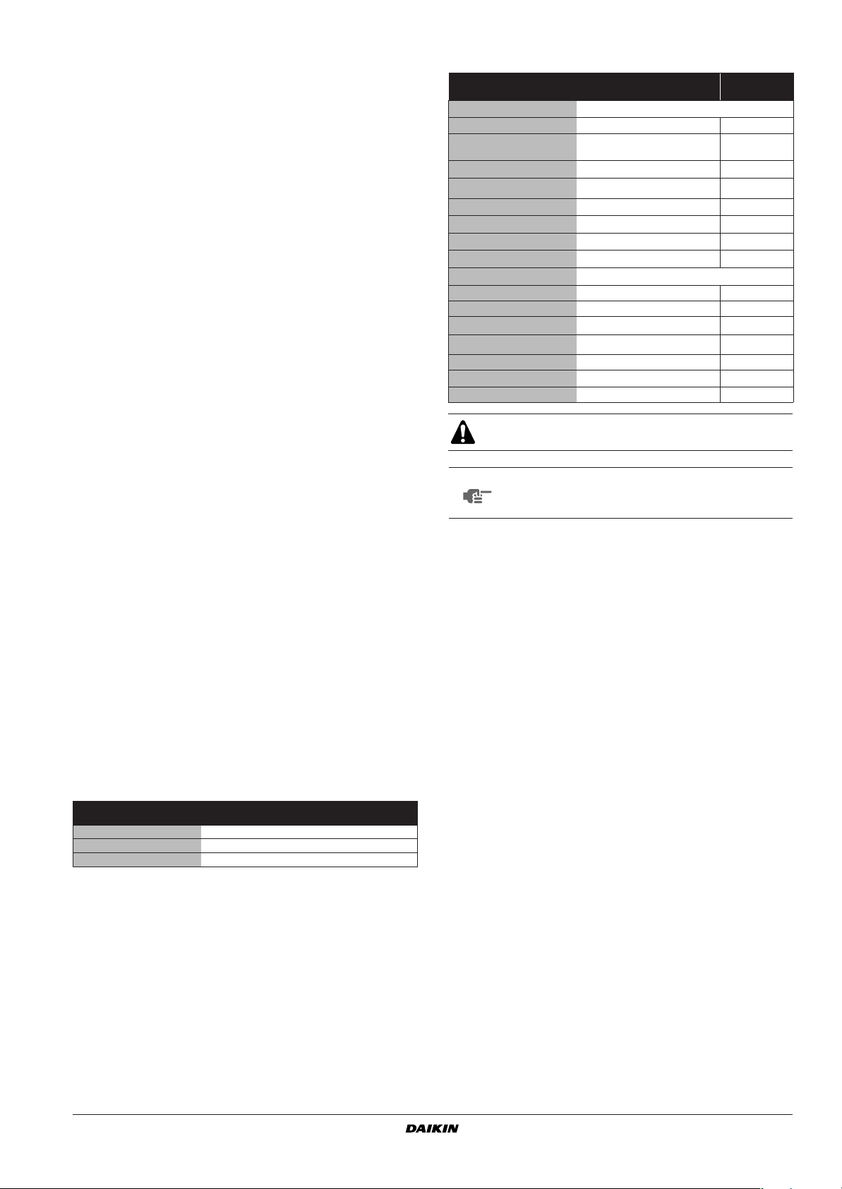
Technical specifications
Model EUWAC 5 8 10
Dimensions HxWxD
Weight
• Machine weight
• Operation weight
Connections
•Water inlet
•Water outlet FBSP 1”
•Water drain
Maximal E.S.P.
(*) E.S.P.=External Static Pressure
(*)
Electrical specifications
Model EUWAC 5 8 10
Power circuit
• Phase 3N~
•Frequency
•Voltage
•Voltage tolerance
(2)
1345x
(mm)
795x605
(kg)
164 224 261
(kg)
166 228 266
FBSP 1” FBSP 1” FBSP 1”
(mm)
(Pa)
25 25 25
100 150 150
1290x
1125x605
FBSP 1” FBSP 1”
(2)
(Hz)
(V)
(%)
50
400
±10
1395x
1275x605
Options
■ Glycol application for chilled water temperature down to –10°C
or –5°C. (**)
(**) Do not use internally Zinc-coated or galvanized steel pipes
for the additional waterpiping.
■ BMS-connection (MODBUS/J-BUS, BACNET)
■ Remote user controller (optional kit EKRUMCA)
Features
■ Lower ambient temperature operation (–10°C DB) due to
integrated head pressure control.
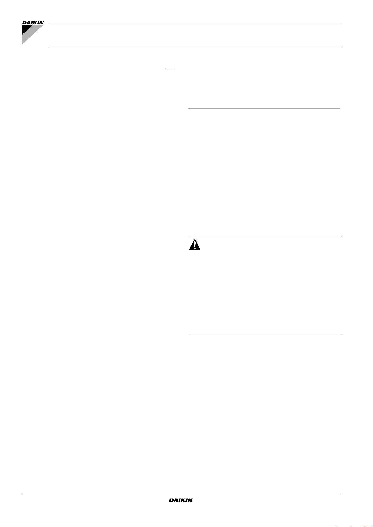
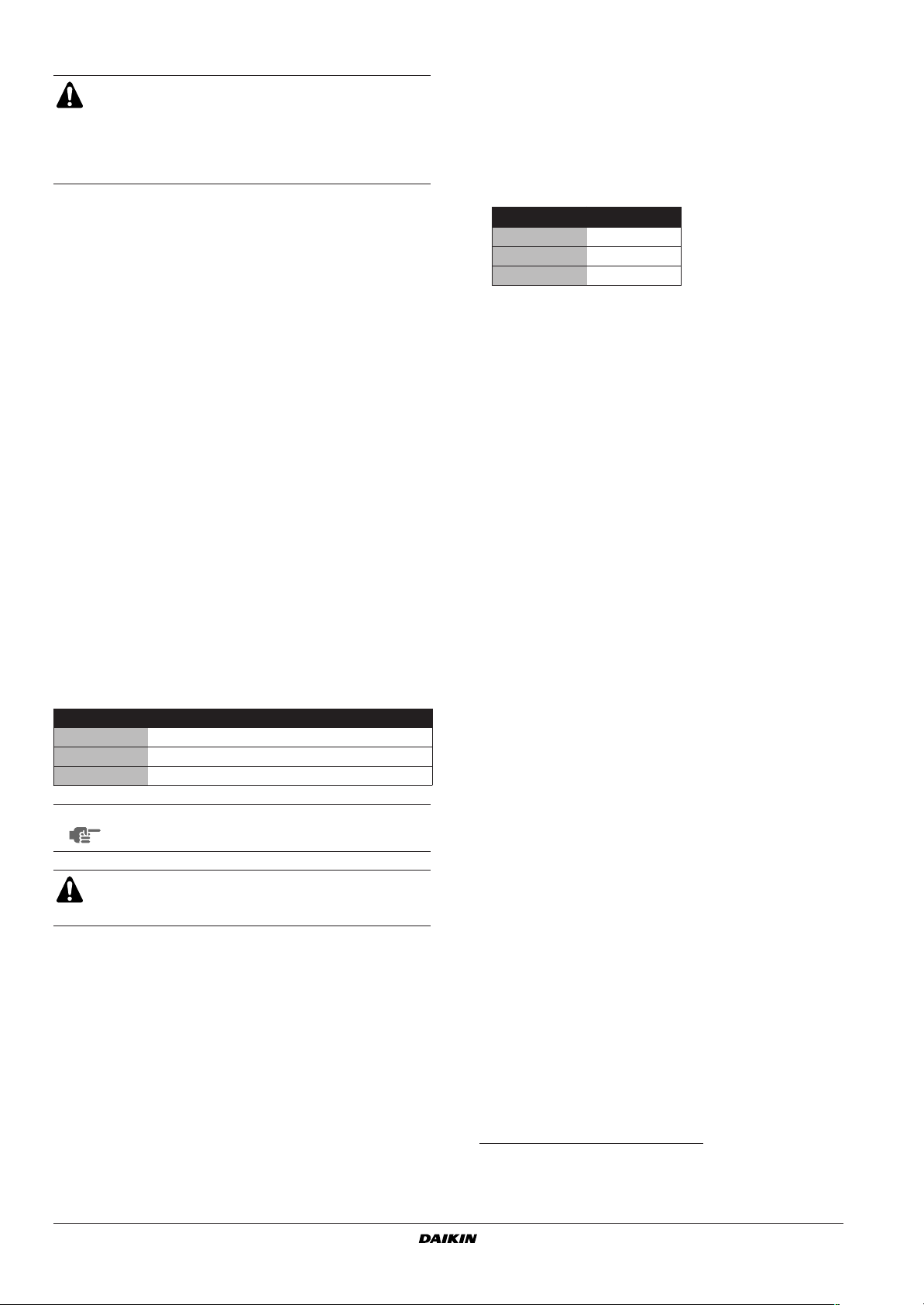
Standard operation range
A
50
43
40
40
36
0
10
20
A
B
C
D
E
F
C
ZL
ZH
–5–10–15–20 11 15
0
Standard operation range
Protect the water piping against water freezing during winter
period
Outdoor ambient temperature (°C DB)
Leaving water temperature evaporator (°C)
Glycol
Water
For nominal E.S.P. of 60 Pa (8 Hp) and of 72 Pa (10 Hp)
For E.S.P. of 150 Pa (8+10 Hp only)
EEFE
F
D
42125
B
MAIN COMPONENTS (See figure 1)
1 Upper service plate
2 Lower service plate
3 Water inlet connection
4 Water outlet connection
5 Power supply intake
6 Digital controller
7 Drain outlet
8 Low pressure gauge (suction pressure)
9 High pressure gauge (discharge pressure)
10 Air inlet ducting flanges
11 Air outlet ducting flanges
12 Identification plate
(1) When EKAC10C is used in combination with remote user controller
EKRUMCA then it is not possible to use the BMS-connection MODBUS.
(2) Refer to the chapter “Operating the unit“ or engineering data book for the
complete list of specifications and options.
EUWAC5~10FBZW1
Packaged air-cooled water chillers
4PW61657-1 – 07.2010
(3) Refer to the chapter “Operating the unit” or engineering data book for the
complete list of specifications and options.
Installation and operation manual
2
SELECTION OF LOCATION
UNPACKING AND PLACING THE UNIT
The EUWAC unit should be installed in a location that meets the
following requirements:
1 The foundation is strong enough to support the weight of the unit
and the floor is flat to prevent vibration and noise generation.
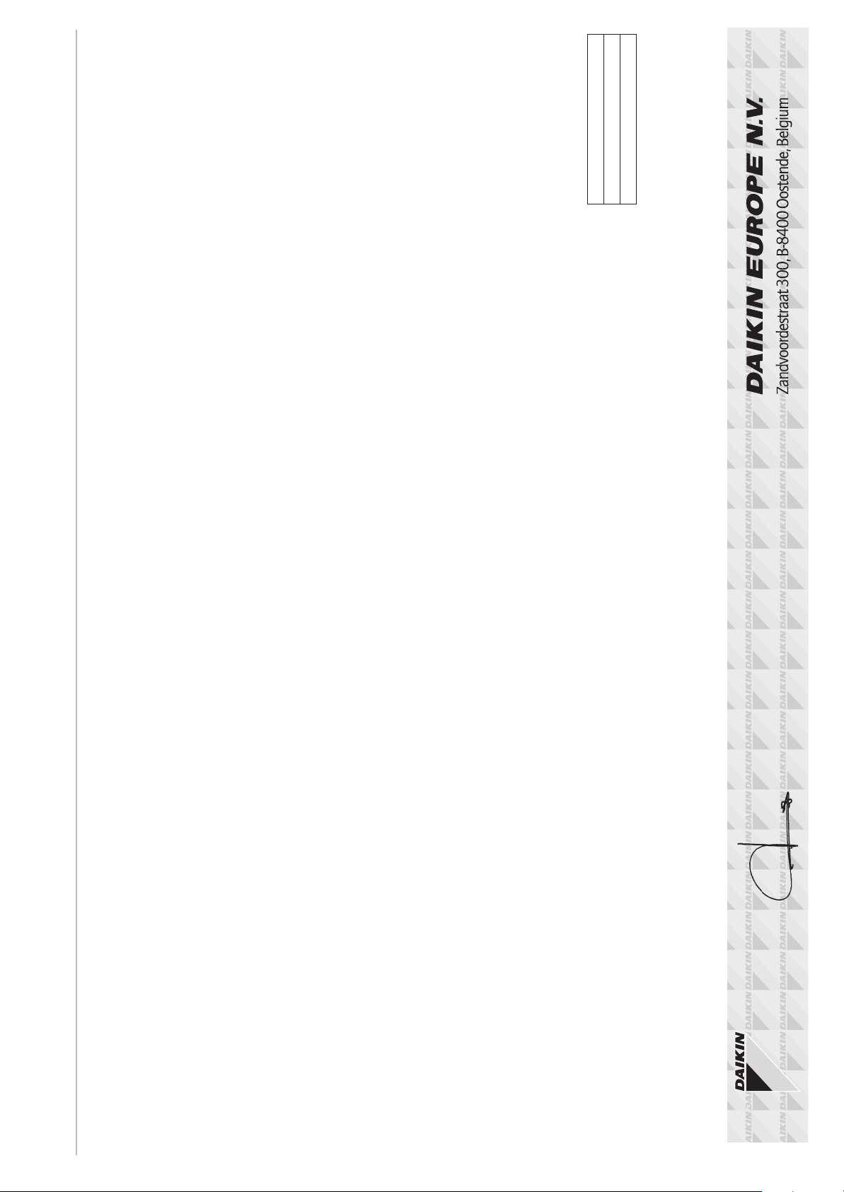
2 The space around the unit is adequate for servicing and the
minimum space for air inlet and air outlet is available. (See
figure 2 and figure 3.)
If several units are being installed side by side in parallel, the
minimum service space between them must be taken into
account.
3 There is no danger of fire due to leakage of inflammable gas.
4 Select the location of the unit in such a way that neither the
discharged air nor the sound generated by the unit disturb
anyone.
5 Make sure that the air inlet and outlet of the unit are not
positioned towards the main wind direction. Frontal wind will
disturb the operation of the unit. If necessary, use a windscreen
to block the wind.
6 Ensure that water cannot cause any damage to the location in
case it drips out of the unit (e.g. in case of a blocked drain pipe).
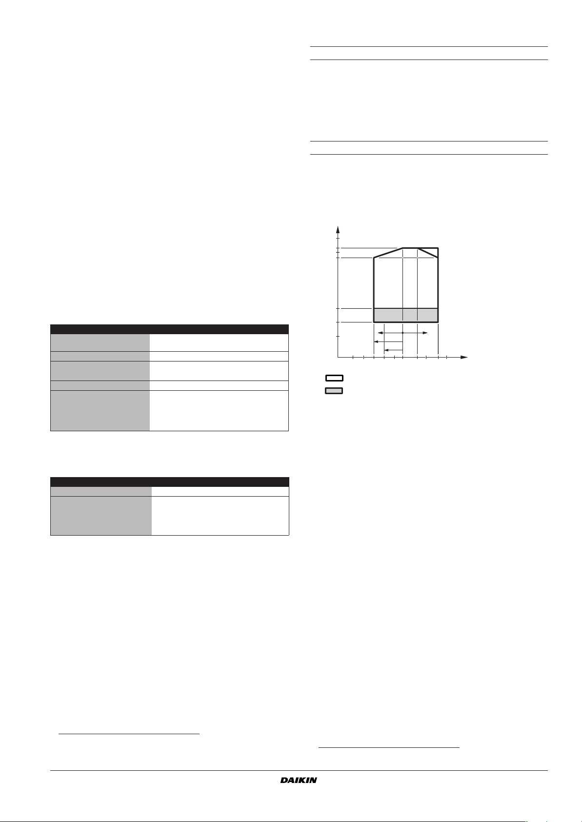
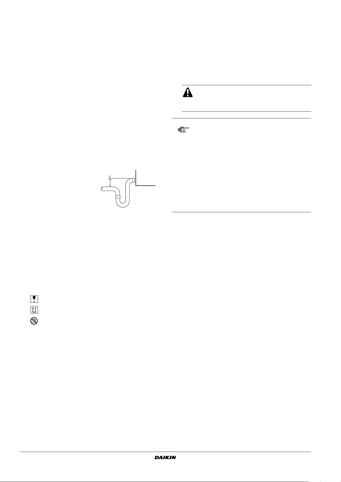
7 A drain is provided and there is
enough space to install a trap
75 mm
with a minimum fall of 75 mm
between the drain outlets of the
unit and the drain.
The equipment is not intended for use in a potentially explosive
atmosphere.
INSPECTING AND HANDLING THE UNIT
The EUWAC units are packed in a cardboard box and attached on a
wooden pallet.
At delivery, the package should be checked and any damage should
be reported immediately to the carrier claims agent.
When handling the unit, take into account the following:
1. Follow the instructions marked by the symbols on the package:
Fragile, handle the unit with care.
Keep the unit upright in order to avoid compressor damage.
Do not use straps to move the unit.
2. Lift the unit preferably with a fork-lift, a manual pallet mover or a
crane and belts.
3. When lifting the unit with a crane, always use protectors to prevent
belt damage and pay attention to the position of the unit’s centre of
gravity.
4. Bring the unit as close to its final installation position in its original
package to prevent damage during transport.
1 Cut the straps and remove the cardboard box from the unit.
2 Remove the four screws fixing the unit to the pallet.
3 Lift the unit from the pallet and place it on its installation position.
4 Connect the air inlet (lower part of the unit) to the air inlet
ducting and the air outlet (upper part of the unit) to the air outlet
ducting. Always provide a flexible connection between the
ducting flanges of the unit and the ducts to prevent vibrations
and noise generation.
Ensure that a protective guard is installed in front of
the air outlet to prevent that the fan blades be
touched. The protection must comply with relevant
European and national regulations.
NOTE
When connecting the unit to the ducting, a pressure
drop will be created and the air flow will be reduced.
The total external pressure drop may not exceed
100 Pa for the EUWAC5 and 150 Pa for the
EUWAC8+10. (For external pressure drop calculation,
refer to "Annex II" on page 21)
The fan pulley has been factory set to work with an
external static pressure of 0 to 150 Pa for the 8 and
10 Hp models. Other pulley settings are possible for
lowering the airflow and thus reducing the sound level
of the unit. But lowering the airflow may lead to
reduced performance (refer to "Troubleshooting" on
page 17).
Also refer to "Annex III" on page 22 for the fan
characteristics.
5 Fasten the unit in place using four anchor bolts.
6 Remove the upper and lower service plate.
7 Connect the drain outlet at one side to the drain. Provide a trap
with a minimum fall of 75 mm in the drain pipe to prevent that the
negative pressure, produced by the fan, disturbs the drain (refer
to figure in chapter "Selection of location" on page 3).
IMPORTANT INFORMATION REGARDING THE
REFRIGERANT USED
This product contains fluorinated greenhouse gases covered by the
Kyoto Protocol. Do not vent gases into the atmosphere.
Refrigerant type: R407C
(1)
GWP
value: 1652.5
(1)
GWP = global warming potential
The refrigerant quantity is indicated on the unit name plate.
Installation and operation manual
3
Packaged air-cooled water chillers
EUWAC5~10FBZW1
4PW61657-1 – 07.2010
CHECKING THE WATER CIRCUIT
The EUWAC units are equipped with a water inlet and water outlet for
connection to a chilled water circuit. This circuit must be provided by
a licensed technician and must comply with all relevant European
and national regulations.
Before continuing the installation of the EUWAC, check the following
points:
1 A circulation pump must be provided in such a way that it
discharges the water directly into the evaporator. A voltage-free
contact is provided in the switch box to steer the pump.
2 A flow switch must be installed in the water outlet pipe to prevent
the unit from operating at a water flow which is too low. A
terminal is provided in the switch box for the electrical
connection of the flow switch.
3 A wire mesh strainer must be installed at the pump suction to
protect the pump and the heat exchanger from foreign matter.
The mesh size has to be between 0.5 and 1.5 mm.
4 Drain taps must be provided at all low points of the system to
permit complete drainage of the circuit during maintenance or in
case of shut down.
5 Air vents must be provided at all high points of the system. The
vents should be located at points which are easily accessible for
servicing. The water inlet pipe is specially designed to obtain a
complete air purge of the evaporator.
6 Provide adequate safeguards in the water circuit to make sure
that the water pressure will never exceed the maximum
allowable working pressure.
CONNECTING THE WATER CIRCUIT
The water quality must be in accordance with the specifications listed
in the table below.
circulating
water
Items to be controlled
pH at 25°C 6.8~8.0 6.8~8.0 corrosion + scale
Electrical conductivity [mS/m]
Chloride ion
Sulphate ion
M-alkalinity (pH4.8)
Total hardness
Calcium hardness
Silica ion
Items to be referred to
Iron [mg Fe/l] <1.0 <0.3 corrosion + scale
Copper [mg Cu/l] <1.0 <0.1 corrosion
Sulphide ion
Ammonium ion
Remaining chloride [mg Cl/l] <0.3 <0.3 corrosion
Free carbide
Stability index ——corrosion + scale
at 25°C
[mg Cl-/l]
2-
[mg SO
4
[mg CaCO3/l]
[mg CaCO3/l]
[mg CaCO3/l]
[mg SiO2/l]
[mg S2-/l]
[mg NH
[mg CO2/l]
+
4
<40 <30 corrosion + scale
<50 <50 corrosion
<50 <50 corrosion
/l]
<50 <50 scale
<70 <70 scale
<50 <50 scale
<30 <30 scale
not detectable not detectable corrosion
<1.0 <0.1 corrosion
/l]
<4.0 <4.0 corrosion
supply water
tendency if out
of criteria
The water pressure should not exceed the maximum working pressure of 10 bar.
NOTE
Provide adequate safeguards in the water circuit to
make sure that the water pressure will never exceed
the maximum allowable working pressure.
Piping connections (water inlet and outlet) must be made from the
right side of the water chiller. (See figure 1)
If air, moisture or dust get in the water circuit, problems may occur.
Therefore, always take into account the following when connecting
the water circuit:
1. Use clean pipes only.
2. Hold the pipe end downwards when removing burrs.
3. Cover the pipe end when inserting it through a wall so that no dust
and dirt enter.
WATER CHARGE, FLOW AND QUALITY
To assure proper operation of the unit, a minimum water volume is
required in the system and the water flow through the evaporator
must be within the operation range, specified in the table below.
Minimum
EUWAC5 16 l/min 64 l/min
EUWAC8 23 l/min 92 l/min
EUWAC10 28 l/min 112 l/min
water flow
The minimum water volume v [kg] in the system should moreover full
fill the criteria below:
v > (Q / 2) x t / (C x y)
Q highest cooling capacity of the unit within the range of
application (kW)
t antirecycling timer of unit (AREC)/2(s)=120 s
C specific heat capacity of the fluidum (kJ/kg°C)=4.186 kJ/kg°C for
water
y steplength (°C)
standard setting=3°C
(refer to the chapter “Operating the unit” for adjustments)
Maximum
water flow
PIPING INSULATION
The complete water circuit, inclusive all piping, must be insulated to
prevent condensation and reduction of the cooling capacity. Take into
account the following points when insulating the piping:
1 Provide a separate insulation for the water inlet and the water
outlet piping.
2 Thoroughly insulate around the pipe connections.
3 Use Armaflex material with thickness of 9 mm.
Protect the water piping against water freezing during winter period
(e.g. by using a glycol solution).
EUWAC5~10FBZW1
Packaged air-cooled water chillers
4PW61657-1 – 07.2010
Installation and operation manual
4
FIELD WIRING
All field wiring and components must be installed by a
licensed electrician and must comply with relevant European
and national regulations.
The field wiring must be carried out in accordance with the
wiring diagram supplied with the unit and the instructions
given below.
Parts table
L1,2,3 .................Live line
N.........................Neutral
F1,2,3U ..............Field fuses
H1P ....................Indication lamp alarm
H3P ....................Indication lamp operation compressor
KP ......................Pumpcontactor
PE ......................Main earth terminal
S9S ....................Switch for remote start/stop or dual setpoint
S10L...................Flowswitch
S11L...................Contact that closes if the pump is working
S12S ..................Main isolator switch
- - -......................Field wiring
Point for attention regarding quality of the public electric power supply
(2)
(1)
provided
max
at
max
■ This equipment complies with EN/IEC 61000-3-11
that the system impedance Z
is less than or equal to Z
sys
the interface point between the user's supply and the public system. It is the responsibility of the installer or user of the equipment to ensure, by consultation with the distribution network
operator if necessary, that the equipment is connected only to a
supply with a system impedance Z
Z
(Ω)
max
EUWAC5 0.15
EUWAC8 0.06
EUWAC10 0.04
less than or equal to Z
sys
■ Equipment complying with EN/IEC 61000-3-12
Cable for flow switch
Be sure to interlock so that the compressor will not come into
operation unless the water pump is operated. For this purpose 2
spare terminals are provided in the switch box (refer to the wiring
diagram supplied with the unit).
HOW TO CONTINUE
.
Power circuit and cable requirements
1 The electrical power supply to the unit should be arranged so
that it can be switched on or off independently of the electrical
supply to other items of the plant and equipment in general.
2 A power circuit (see table below) must be provided for
connection of the packaged air-cooled water chiller. This circuit
must be protected with the required safety devices, i.e. a circuit
breaker, a slow blow fuse on each phase and an earth leak
detector.
Recommended fuses are mentioned on the wiring diagram
supplied with the unit.
Phase and frequency Voltage
EUWAC5 3N~ 50 Hz 400 V
EUWAC8 3N~ 50 Hz 400 V
EUWAC10 3N~ 50 Hz 400 V
NOTE
Select the power cable in accordance with relevant
local and national regulations.
Switch off the main isolator switch before making any
connections (switch off the circuit breaker and remove or
switch off the fuses).
Connection of the packaged air-cooled water chiller power supply
After installation and connection of the packaged air-cooled water
chiller, the unit should be checked and tested as described in
"Checks before initial start-up" on page 8 in the chapter "Before
operation".
1 Using the appropriate cable, connect the power circuit to the (N),
L1, L2 and L3 terminals of the unit as shown on the wiring
diagram.
2 Connect the earth conductor (yellow/green) to the earthing
terminal PE.
Installation and operation manual
5
(1) European/International Technical Standard setting the limits for voltage
changes, voltage fluctuations and flicker in public low-voltage supply
systems for equipment with rated current ≤75 A.
(2) European/International Technical Standard setting the limits for harmonic
currents produced by equipment connected to public low-voltage systems
with input current >16 A and ≤75 A per phase.
Packaged air-cooled water chillers
EUWAC5~10FBZW1
4PW61657-1 – 07.2010
OPERATING THE UNIT
INTRODUCTION
This manual has been prepared to ensure adequate operation and
maintenance of the unit. It will tell you how to use the unit properly
and will provide help if problems occur. The unit is equipped with
safety devices, but they will not necessarily prevent all problems
caused by improper operation or inadequate maintenance.
In case of persisting problems contact your local Daikin dealer.
Before starting up the unit for the first time, make sure that
it has been properly installed. It is therefore necessary to
carefully read the chapter "Installing the unit" on page 1
and the recommendations listed in "Checks before initial
start-up" on page 8.
DESCRIPTION
The EUWAC packaged air-cooled water chillers are available in 3
standard sizes with nominal cooling capacities ranging from 11.2 to
22.6 kW. Each size is available in three phase 400 V+N 50 Hz.
(See figure 4)
1 Compressor (M1C)
2 Condenser coil
3 Condenser fan with motor (M11F) (only for EUWAC5)
4 Condenser fan (only for EUWAC8+10)
5 Condenser motor (M11F) (only for EUWAC8+10)
6 High pressure gauge
7 Low pressure gauge
8 Drier/filter
9 Thermostatic expansion valve
10 Evaporator
11 Water inlet connection
12 Water outlet connection
13 Switch box
14 Low-pressure switch (S4LP)
15 High-pressure switch (S1HP)
16 Digital controller
As the refrigerant circulates through the unit, changes in its state or
condition occur. These changes are caused by the following main
components:
■ Compressor
The compressor (M1C) acts as a pump and circulates the
refrigerant in the refrigeration circuit. It compresses the
refrigerant vapour coming from the evaporator at the pressure at
which it can easily be liquefied in the condenser.
■ Condenser
The function of the condenser is to change the state of the
refrigerant from gaseous to liquid. The heat gained by the gas in
the evaporator is discharged through the condenser to the
ambient air, and the vapour condenses to liquid. One fan
(EUWAC5) or two fans (EUWAC8+10) are used to accelerate
this process.
■ Filter
The filter installed behind the condenser removes small particles
from the refrigerant to prevent blockage of the expansion valve
and tubes.
■ Thermostatic expansion valve
The liquid refrigerant coming from the condenser enters the
evaporator via a thermostatic expansion valve. The valve
maintains a constant degree of suction superheat at the
evaporator outlet in order to ensure a maximum liquid refrigerant
has turned into gas.
■ Evaporator
The main function of the evaporator is to take heat from the
water that flows through it. This is done by turning the liquid
refrigerant, coming from the condenser, into gaseous
refrigerant.
■ Water in/outlet connection
The water inlet and outlet connections allow an easy connection
of the packaged air-cooled water chiller to the water circuit of the
air handling unit or industrial equipment.
Function of the main components (See figure 5)
1 Compressor
2 Condenser
3 Evaporator
4 Expansion valve
5 Filter
6 Low pressure switch
7 High pressure switch
8 Water inlet temperature sensor
9 Water outlet temperature sensor
10 Condenser fan motor
EUWAC5~10FBZW1
Packaged air-cooled water chillers
4PW61657-1 – 07.2010
Installation and operation manual
6

Safety devices
Internal wiring - Parts table
In its standard version, the unit is equipped with the following safety
devices:
■ Overcurrent relay (general safety device)
The overcurrent relay (K4S) is located in the switch box of the
unit and protects the compressor motor in case of overload,
phase failure or too low tension. The relay is factory-set and may
not be adjusted. When activated, it must be reset manually.
■ High-pressure switch (general safety device)
The high-pressure switch (S1HP) is installed on the discharge
pipe of the unit and measures the condenser pressure (pressure
at the outlet of the compressor). When the pressure is too high,
the pressure switch is activated and the unit stops.
The switch is factory-set and may not be adjusted. The switch
resets automatically, but the controller needs to be reset
manually.
■ Low pressure switch (general safety device)
The low-pressure switch (S4LP) is installed on the suction pipe
of the unit and measures the suction pressure (pressure at the
inlet of the compressor). When the pressure is too low, the
pressure switch is activated and the unit stops.
The switch is factory set and may not be adjusted. The switch
resets automatically, but the controller needs to be reset
manually.
■ Reverse phase protector (general safety device)
The reverse phase protector (R1P) is installed in the switch box
of the unit. It prevents the compressor from running in the wrong
direction. If the unit does not start, two phases of the power
supply must be inverted.
■ Discharge thermal protector (general safety device)
The discharge thermal protector (Q*D) is activated when the
temperature of the refrigerant leaving the compressor becomes
too high. When the temperature returns to normal, the protector
resets automatically, but the controller needs to be reset
manually.
■ Fan motor thermal protector (part safety device)
The fan motor is equipped with a thermal protector (Q11F). The
protector is activated when the fan motor temperature becomes
too high.
When the temperature returns to normal, the protector resets
automatically.
■ Outlet water temperature sensor (general safety device)
The outlet water temperature sensor (R4T) measures the
temperature of the water at the water heat exchanger outlet. The
protection device shuts down the circuit when the temperature of
the chilled water becomes too low in order to prevent freezing of
the water during operation.
When the outlet water temperature returns to normal, the
protector resets automatically, but the controller needs to be
reset manually.
■ Additional interlock contact (general safety device)
To avoid that the unit could be started or run without water
circulating through the evaporator, an interlock contact (S10L) of
e.g. a flow switch must be switched in the start-up circuit of the unit.
Measuring devices
Checking the high and low pressure of the refrigerant circuit is necessary to ensure the proper operation of the unit and to guarantee that
the rated output will be obtained. The unit has therefore been
equipped with a high and low pressure gauge. Refer to the checklist
in the chapter "Switching the unit on" on page 10.
■ High pressure gauge
The high pressure gauge indicates the discharge pressure
(pressure at the outlet of the compressor).
■ Low pressure gauge
The low pressure gauge indicates the suction pressure
(pressure at the inlet of the compressor).
Refer to the internal wiring diagram sticker on the unit.
The abbreviations used are listed below:
A1P.................... PCB: Terminal unit
A2P............. ** ... PCB: Adress card (for optional BMS)
A3P.................... PCB: Fanspeed controller (5 Hp only)
A71P.................. PCB: power supply card
A72P.................. PCB: remote user interface
C1...................... Capacitor for fanmotor
E1H.................... Crankcase heater
F1,2,3U....... # .... Fuses
F5 ...............## .. Surge proof fuse
F5B.................... Fuse for control circuit
F7B.................... Fuse for fan circuit
F9B.................... Fuse for secondary of TR1
F8U.................... Surge-proof fuse
F9U............. ## .. Surge-proof fuse (for optional BMS)
H1P.............*..... Indication lamp alarm
H3P.............*..... Indication lamp operation compressor
K1M ................... Compressor contactor
K4S.................... Over current relay
K1A.................... Auxiliary relay for high pressure
K1F,K3F ............. Contactor for high speed selection of the fan motor
(8+10 Hp only)
K2F.................... Contactor for low speed selection of the fan motor
(8+10 Hp only)
KP............... *..... Pumpcontactor
M11F ................. Fan motor
M1C................... Compressor motor
PE...................... Main earth terminal
Q1D ................... Discharge thermal protector
Q11F.................. Fan thermal protector
R1P.................... Reverse phase protector
R3T.................... Inlet water temperature sensor
R4T.................... Outlet water temperature sensor
S1HP ................. High pressure switch
S4LP.................. Low pressure switch
S4PC ................. Head pressure switch for fanspeed control
(8+10 Hp only)
S9S............. *..... Switch for remote start/stop or dual setpoint
S10L ........... # .... Flowswitch
S11L ........... # .... Contact that closes if the pump is working
S12S........... # .... Main isolator switch
TR1.................... Transfo 230 V ➞ 24 V (30 VA) for power supply of
controllers
X1 ...................... Connector in terminal unit for digital inputs, analog
inputs, analog outputs and for power supply
controller
X2 ...................... Connector in terminal unit for digital outputs
Not included with standard unit
Not possible as option Possible as option
Obligatory # ##
Not obligatory * **
Installation and operation manual
7
Packaged air-cooled water chillers
EUWAC5~10FBZW1
4PW61657-1 – 07.2010

BEFORE OPERATION
Checks before initial start-up
Make sure that the circuit breaker on the power supply
panel of the water chiller is switched off.
After the installation of the water chiller, check the following before
switching on the circuit breaker:
1 Field wiring
Make sure that the field wiring between the local supply panel
and the water chiller has been carried out according to the
instructions described in the chapter “Installing the unit”,
according to the wiring diagram and according to European and
national regulations.
2 Additional interlock contact
An additional interlock contact S11L should be provided (e.g.
flow switch or contact of pump motor contactor). Make sure that
it has been installed between the appropriate terminals (refer to
the wiring diagram supplied with the unit). S11L should be a
normal open contact.
3 Fuses or protection devices
Check that the fuses or the locally installed protection devices
are of the size and type specified in the chapter “Installing the
unit”. Make sure that neither a fuse nor a protection device has
been bypassed.
4 Earth wiring
Make sure that the earth wires have been connected properly
and that the earth terminals are tightened.
5 Internal wiring
Visually check the switch box on loose connections or damaged
electrical components.
6 Fixation
Check that the unit is properly fixed, to avoid abnormal noises
and vibrations when starting up the unit.
7 Damaged equipment
Check the inside of the unit on damaged components or
squeezed pipes.
8 Refrigerant leak
Check the inside of the unit on refrigerant leakage. If there is a
refrigerant leak, call your local Daikin dealer.
9 Oil leak
Check the compressor on oil leakage. If there is an oil leak, call
your local Daikin dealer.
10 Air inlet/outlet
Check that the air inlet and outlet of the unit is not obstructed by
paper sheets, cardboard, or any other material. Clean the inside
of the ducts and make sure that the air ducts are properly
installed.
11 Protective guard
Check that the protective guard(s) is (are) properly installed in
front of the air outlet(s).
12 Drain disposal
Check the proper operation of the drain. Pour some water into
the drain pan and check whether the water evacuates freely
through the drain.
Water supply
Fill the water piping, taking into account the minimum water volume
required by the unit. Refer to the chapter “Installing the unit”.
Make sure that the water is of the quality as mentioned in the chapter
“Installing the unit”.
Purge the air at the high points of the system and check the operation
of the circulation pump and the flow switch.
Power supply connection and crankcase heating
In order to avoid compressor damage, it is necessary to
switch on the crankcase heater for at least six hours
before starting the compressor after a long period of standstill.
To switch on the crankcase heater proceed as follows:
1 Switch on the circuit breaker on the local supply panel. Make
sure that the unit is “OFF”.
2 The crankcase heater is switched on automatically.
3 Check the supply voltage on the supply terminals L1, L2, L3, (N)
by means of a voltmeter. The voltage should correspond to the
voltage indicated on the identification label of the unit. If the
voltmeter reads values which are not within the ranges specified
in the technical data, check the field wiring and replace the
supply cables if necessary.
4 Check the LED on the reverse phase protector. If it lights up, the
phase order is correct. If not, switch off the circuit breaker and
call a licensed electrician to connect the wires of the power
supply cable in the correct phase order.
After six hours, the unit is ready for operation.
General recommendations
Before switching on the unit, read following recommendations:
1 When the complete installation and all necessary settings have
been carried out, close all front panels of the unit.
2 The service panel of the switch box may only be opened by a
licensed electrician for maintenance purposes.
OPERATION
The EUWAC units are equipped with a digital controller offering a
user-friendly way to set up, use and maintain the unit.
This part of the manual has a task-oriented, modular structure. Apart
from the first section, which gives a brief description of the controller
itself, each section or subsection deals with a specific task you can
perform with the unit.
EUWAC5~10FBZW1
Packaged air-cooled water chillers
4PW61657-1 – 07.2010
Installation and operation manual
8

Digital controller
User interface
The digital controller consists of a numeric display, four labelled keys
which you can press and LEDs providing extra user information.
Figure - Digital controller
Figure - Remote user interface (optional kit)
Keys provided on the controller:
The function carried out when the user presses one or a combination
of these keys depends on the status of the controller and the unit at
that specific moment.
Keys digital
controller
AT
BU
A + BS
CC
DD
C + DR
Keys remote
interface
Main display Sensor readout menu Parameter selection menu Parameter setting menu
— Press once:
Press for 5 seconds:
To be able to access
DIRECT parameters
Press for 5 seconds:
A + B OR
Press once:
S
To be able to access USER
parameters (after entering
USER password)
Press for 5 seconds:
No effect on these units
Press once: Direct access to
readout menu sensor
(b01/b02/b03)
Press for 5 seconds:
Switch unit on/off in cooling
mode
Press once: Direct access to
readout menu sensor
(b01/b02/b03)
Press for 5 seconds:
Manually alarm reset in the
event of alarm
Select previous sensor
Return
—
Press once:
parameter
Press once:
Select next sensor
parameter
Press once:
Return
Press once:
Select parameter group or
parameter
—
Press once:
Select previous parameter
group or parameter
Press once:
Select next parameter group
or parameter
—
Press once:
Cancel and return
Press once:
Confirm and return
Press once:
Increase value
Press once:
Decrease value
Installation and operation manual
9
Packaged air-cooled water chillers
EUWAC5~10FBZW1
4PW61657-1 – 07.2010

LEDs provided on the controller and remote interface:
Function during main display (not inside menu)
Remote
Leds digital controller
Led (green) Z Inlet water temperature.
P
Led (amber)
F
Led (amber)
G
H
L
M
&
é
Led (red) Y
Led (amber)
Led (amber)
Led (amber)
Led (amber)
interface
F
G
L
M
&
é
Main display
Not active.
Indicates that cooling mode is
active.
Indicates that the alarm is
active.
Indicates the status of the
pump
LED, indicates that at least
one compressor is active.
LED is on, indicates that
compressor 1 is active.
LED is flashing, indicates
compressor 1 startup request.
Not active.
When selecting a parameter group or parameter, different LEDs
related to the parameter group or parameter are displayed.
Example: The LEDs F and G are displayed when accessing a
parameter group or when accessing parameters directly.
NOTE
Temperature readout tolerance: ±1°C.
Legibility of the numeric display may decrease in direct
sunlight.
Direct and user parameters
The digital controller provides direct and user parameters. The direct
parameters are important for the everyday usage of the unit, e.g. to
adjust the temperature setpoint or to consult actual operational
information. The user parameters on the contrary provide advanced
features such as adjusting time delays.
Each parameter is defined by a code and a value. For example: the
parameter used to select local or remote on/off control has code
h07 and value 1 or 0.
For an overview of the parameters, refer to "Overview of the direct
and user parameters" on page 13.
Working with the units
This chapter deals with the everyday usage of the units. Here, you
will learn how to perform routine tasks, such as:
■ "Switching the unit on" on page 10 and "Switching the unit off"
on page 11,
■ "Adjusting the cooling temperature setpoint" on page 11,
■ "Consulting actual operational information" on page 11,
■ "Resetting alarms" on page 11,
■ "Resetting warnings" on page 12.
Switching the unit on
To switch the unit on in cooling mode, proceed as follows:
1 Press the D key for approximately 5 seconds, the G LED will
be displayed.
Then an initialization cycle is started, the L LED, the M LED, the &
LED will light up depending on the programmed thermostat function.
In case the & LED is flashing, it indicates that there is a
compressor 1 startup request. The compressor will start after the
timer has reached zero.
NOTE
2 When the unit is started up for the first time, or when the unit has
Cooling mode Minimum Nominal Maximum
Low pressure 3 bar 4 bar 6.5 bar
High pressure 7 bar 21 bar 24 bar
outdoor temperature
LW leaving water temperature
NOTE
If remote on/off control is enabled, refer to "Selecting
local or remote on/off control" on page 14.
been out of operation for a longer period, it is recommended to
go through the following checklist.
Condenser fan rotation
This check applies to the EUWAC8+10 units only.
As soon as the compressor and the condenser fan have started,
switch off the unit to stop them (refer to "Switching the unit off"
on page 11). Check if the fans turn in the right direction while
they are running out. The direction is indicated by an arrow on
the fan housing. If they run in the wrong direction, call your local
Daikin dealer.
Abnormal noise and vibrations
Make sure the unit does not produce any abnormal noises or
vibrations: check the fixations and piping. If the compressor
makes any abnormal noises, this may also be caused by an
overcharge of refrigerant.
Working pressure
It is important to check the high and low pressure of the
refrigerant circuit to ensure the proper operation of the unit and
to guarantee that the rated output will be obtained.
For reference, the average saturated temperature of R407C in
relation to the pressure readout can be found in "Annex I" on
page 21.
The pressures measured will vary between a maximum
and minimum value, depending on the water and outdoor
temperatures (at the moment of measurement).
( –5°C) ( 35°C) ( 38°C)
(LW 4°C) (LW 7°C) (LW 20°C)
Make sure that the lower service plate is in place when
carrying out the pressure measurements. If not, the
refrigerant will be cooled less in the condenser, which
results in an increase of the low and high pressure.
EUWAC5~10FBZW1
Packaged air-cooled water chillers
4PW61657-1 – 07.2010
Installation and operation manual
10

Water leaks
Check the evaporator and the external water circuit on water
leaks.
Drain disposal
Put the service covers in place so that the unit is completely
closed, and start up the unit. After a few hours of operation,
check if the condensing water is evacuated properly through the
drain and that it does not flow over from the drain pan on the
floor.
It may happen that the drain pan outlet is obstructed or that the
condenser fans create a vacuum so that the condensing water
remains in the drain pan and flows over. In this case, the drain
disposal should be lowered. The level difference of 75 mm
indicated in the chapter “Installing the unit” is a minimum.
3 If the unit does not start after a few minutes, consult the actual
operational information available in the list of direct parameters.
Also refer to the chapter "Troubleshooting" on page 17.
NOTE
In case of remote on/off control (h07=1), it is recommended to install an on/off switch near the unit in
series with the remote switch. The unit can then be
switched off from either place.
Switching the unit off
To switch the unit off and cooling mode is active, proceed as follows:
1 Press the D key for approximately 5 seconds, the G LED will
be extinguished.
NOTE
If remote on/off control is enabled, refer to "Selecting
local or remote on/off control" on page 14.
How to consult and modify the direct parameters
For an overview of the menu structure, refer to "Menu overview" on
page 20.
1 Press B for 5 seconds in the main display.
The -/- parameter group is displayed.
2 Press the C or D key to select the required parameter
group.
3 Press the B key to enter the selected parameter group.
4 Press the C or D key to select the required parameter.
5 Press the B key to consult the selected parameter.
6 Press the C or D key to raise, respectively lower the
setting of the selected parameter. (Only valid for read/write
parameters.)
7 Press the B key to confirm the modified setting.
OR
Press the A key to cancel the modified setting.
8 Press the A key to return to the parameter group.
9 Press 2 times the A key to return to the main display.
If during the procedure no buttons are pressed for 30 seconds, the
displayed parameter code or value will start flashing. After another
30 seconds without pressing any buttons, the controller automatically
returns to the main display without saving any modified parameter.
How to consult the "sensor readout menu" parameters
For an overview of the menu structure, refer to "Menu overview" on
page 20.
The b01/b02/b03 parameters are part of the "sensor readout
menu".
1 Press the C or D key in the main display.
The b01 parameter is displayed.
In case no buttons are pressed, the value of the b01 sensor will
be displayed until C or D is pressed again to select
another parameter (b02 or b03).
2 Press the A key to return to the main display.
If during the procedure no buttons are pressed for 30 seconds, the
displayed parameter code or value will start flashing. After another
30 seconds without pressing any buttons, the controller automatically
returns to the main display.
Adjusting the cooling temperature setpoint
1 Modify the r1 cooling setpoint parameter.
This is a direct parameter, refer to "How to consult and modify the
direct parameters" on page 11.
NOTE
When dual setpoint is enabled (refer to "Selecting dual
setpoint control" on page 14).
Consulting actual operational information
The actual operational information that can be consulted in the list of
direct parameters consists of:
■ b01:Evaporator inlet water temperature,
■ b02:Evaporator outlet water temperature,
■ b03: Not used,
■ c10:Total running hours of the compressor 1,
■ c15:Total running hours of the pump.
NOTE
■ The parameters b01, b02 and b03 can also be
consulted by the "sensor readout menu". Refer to
"How to consult the "sensor readout menu"
parameters" on page 11.
■ To reset the timers of parameters c10, c11 and
c15 refer to "Resetting warnings" on page 12.
These are direct parameters, refer to "How to consult and modify the
direct parameters" on page 11.
Resetting alarms
When an alarm is detected, the following happens:
■ the alarm relay is energized,
■ the H LED is displayed
■ the display starts flashing, alternately showing the alarm code
and the inlet water temperature.
The following alarm codes may appear on the screen:
■ a1: indicates an anti-freeze alarm.
■ e1: indicates that the NTC probe used to measure the
■ e2: indicates that the NTC probe used to measure the
■ e3: indicates that the fuse for the evaporator heatertape (F4)
evaporator inlet water temperature is defective.
evaporator outlet water temperature is defective.
is blown or that there is a reverse phase error or that there
is a problem with the I/O PCB (A2P).
Installation and operation manual
11
Packaged air-cooled water chillers
EUWAC5~10FBZW1
4PW61657-1 – 07.2010

In case the unit is equipped with freeze protection, it is
highly recommended to install the remote indicator
lamp alarm (H3P) (see wiring diagram supplied with
the unit). By doing so, breakdown of the fuse for the
evaporator heatertape (F4) will be detected sooner
and freezing of the circuit will be avoided during cold
weather.
■ ehs: indicates that the supply voltage is exceedingly high. In
this case contact a licensed electrician.
■ el1: indicates that there is a power supply error (example:
noise). In this case contact a licensed electrician.
■ el2: indicates that there is a power supply error (example:
noise). In this case contact a licensed electrician.
■ els: indicates that the supply voltage is exceedingly low. In this
case contact a licensed electrician.
■ epb: indicates that the EEPROM on the controller PCB inside
the unit is defective.
■ epr: indicates that the EEPROM on the controller PCB inside
the unit is defective.
■ fl: indicates that there was no sufficient water flow either
during the period of 15 seconds after the pump was
started or for 5 seconds while the compressor is active or
that the overcurrent protection of the pump is activated.
■ hp1: indicates that a high pressure switch, the discharge
thermal protection or the overcurrent protection of the
compressor motor is activated or that the NTC probe used
to measure the ambient temperature is defective.
fl + hp1
■
: indicates that there is most likely an RPP error or that the
F4 fuse is blown.
■ lp1: indicates that the low pressure switch is activated.
■ ter: indicates that there is a remote user interface
communication error.
■
:
communication failure between the digital controller of the
unit and the remote user interface. Confirm the correct
selection of parameter code h23. This should be default
setting 0 and confirm the correction installation according
to the installation manual of the remote user interface
EKRUMCA.
Resetting warnings
During normal operation, the display of the controller may start
flashing, alternately showing the inlet water temperature and the
following warning code:
■ hc1: indicates that the compressor 1 requires maintenance:
the total running hours of the compressor 1 (direct
parameter c10) has exceeded the setting of the timer
threshold for maintenance warning (user parameter
c14).
To reset the maintenance warning hc1, proceed as follows:
1 Consult c10 running hours of compressor 1.
This is a direct parameter, refer to "How to consult and modify
the direct parameters" on page 11.
2 When c10 parameter value is displayed, press the C and
D key simultaneously for 5 seconds. The value of the timer
becomes 0 and the warning is reset.
NOTE
Do not forget to carry out the required maintenance
activities after resetting the timers.
Besides resetting timer c10, it is also possible to reset
timer c15 (running hours of pump) in the same way.
NOTE
If the alarm codes fl and h1 are flashing alternately,
the alarm is most probably caused by the reverse
phase protector or by the fuse for evaporator heatertape (F4) that was blown.
To reset an alarm, proceed as follows:
1 Find the cause of shutdown and correct.
Refer to the chapter "Troubleshooting" on page 17.
2 If the alarm codes a1, fl, hp1 or lp1 appear on the display,
reset the alarm manually by pressing the E combination keys
C and D simultaneously for approximately 5 seconds.
In all other cases the alarm is reset automatically.
Once the alarm is reset, the error code and the H LED no longer
appears on the display. The controller continues its normal
operation, displaying the inlet water temperature.
EUWAC5~10FBZW1
Packaged air-cooled water chillers
4PW61657-1 – 07.2010
Installation and operation manual
12

Advanced features of the digital controller
This chapter gives an overview of the direct parameters and user
parameters provided by the controller. In the following chapter, you
will learn how you can set up and configure the unit using these
parameters.
Overview of the direct and user parameters
The list of direct parameters is accessible by pressing the B key
for approximately 5 seconds. Refer also to "How to consult and
modify the direct parameters" on page 11.
Parameter
group
-/- /23
Parameter
code
Description
Measurement unit
0=°C 1=°F
Default
value
Min Max Units
Read/
Write
User/
Direct
Modbus
Address
001 R/W U 5 D
-a- No user or direct parameters accessible
b01 Evaporator inlet water temperature 0.1°C R D 102 A
-b-
b02 Evaporator outlet water temperature 0.1°C R D 103 A
b03 Not used 0.1°C R D 104 A
Time delay between pump startup and
compressor startup
Time threshold between the unit
shutdown and the pump shutdown
Maintenance threshold for
maintenance warning (c10)
15 0 999 1 sec R/W U 238 I
00150 1 min R/W U 239 I
00100 x100 hours R/W U 241 I
-c-
c07
c08
c10 Total running hours of compressor 1 x100 hours R D 122 A
c14
c15 Total running hours of pump x100 hours R D 126 A
-d- No user or direct parameters accessible
-f- No user or direct parameters accessible
To activate remote on/off control
h07
0=not active
1=active
001 R/W U 15 D
(only in case p34=23)
To lock the controller keyboard
-h-
h09
0=lock
1=unlock
101 R/W U 16 D
h10 Serial address for BMS connection 1 1 200 R/W U 256 I
To select address card connection
h23
0=remote user interface connection
001 R/W U 11 D
1=MODBUS connection
Changeable digital input selection
S9S
-p- p34
0=no function
13=remote dual setpoint
23=remote on/off (only active in
23 0 27 R/W U 329 I
combination with h07)
DO NOT SELECT OTHER VALUES
7.0
7.0
(†)
25.0 0.1°C R/W D 41 A
(†)
25.0 0.1°C R/W D 55 A
-r-
r01
Cooling setpoint
12.0
r02 Cooling difference 3.0 0.3 19.9 0.1°C R/W D 42 A
r21
Cooling setpoint 2
(‡)
12.0
-t- No user or direct parameters accessible
f-r h99 Software release version R D 208 I
(*) D=digital, A=analog, I=integer.
(†) –2.0 and –7.0 only applicable for units with glycol applications.
(‡) Used in case dual setpoint is enabled in p09 or p34 and dual setpoint digital input is closed.
Parameter
(*)
type
Installation and operation manual
13
Packaged air-cooled water chillers
EUWAC5~10FBZW1
4PW61657-1 – 07.2010

How to consult and modify the user parameters
NOTE
For an overview of the menu structure, refer "Menu overview" on
page 20.
1 In case of digital controller, press the A and B keys for
2 Enter the correct password by using the C and D keys.
3 Press the B key to confirm the password and to enter the
4 Press the B key to consult the parameter settings (=s-p).
5 Press the C or D key to select the required parameter
6 Press the B key to enter the selected parameter group.
7 Press the C or D key to select the required parameter.
8 Press the B key to consult the selected parameter.
9 Press the C or D key to increase, respectively decrease
10 Press the B key to confirm the modified setting.
11 Press the A key to return to the parameter group.
12 Press 2 times the A key to return to the main display.
If during the procedure no buttons are pressed for 30 seconds, the
displayed parameter code or value will start flashing. After another
30 seconds without pressing any buttons, the controller automatically
returns to the main display without saving any modified parameter.
When user parameters are consulted, the direct
parameters are displayed as well.
approximately 5 seconds until O is displayed.
In case of remote user interface, push S once.
The password’s value is 22.
menu, s-p is displayed.
(l-p means consulting the parameter level, but this function is
not used).
The -/- parameter group is displayed.
group.
the setting. (Only valid for read/write parameters.)
OR
Press the A key to cancel the modified setting.
Defining the cooling temperature differential
Modify the r02 cooling differential parameter.
This is a direct parameter, refer to "How to consult and modify the
direct parameters" on page 11.
for 1 compressor
compressor
ON
OFF
12 15
r02
r01/
temperature of
°C
inlet water
evaporator
r21
Tasks carried out using user parameters
Defining the measurement unit
Depending on the setting of user parameter /23 (measurement
unit), all temperature values are displayed in °C (=0) or in °F (=1).
This is a user parameter, refer to "How to consult and modify the user
parameters" on page 14.
Defining the time delay between pump and compressor
startup
User parameter c07 allows you to define the time delay between the
pump startup and the compressor startup.
This is a user parameter, refer to "How to consult and modify the user
parameters" on page 14.
Defining the time delay between unit and pump shutdown
User parameter c08 allows you to define the time delay between the
unit shutdown and the pump shutdown, more specifically the period
during which the pump will still be active after the unit has been shut
down.
This is a user parameter, refer to "How to consult and modify the user
parameters" on page 14.
Defining the timer threshold for maintenance warning
User parameter c14 allows you to define a timer threshold (running
hours of the compressor) after which the controller will generate a
maintenance warning or request.
This is a user parameter, refer to "How to consult and modify the user
parameters" on page 14.
Selecting local or remote on/off control
User parameter h07 in combination with the remote on/off switch
(installed by the customer) allows the user to switch the unit on
without using the D or C key on the controller.
■ When user parameter h07 is set to 0 (=not active), the unit can
only be switched on by means of the D and C key on the
controller.
■ When user parameter h07 is set to 1 (=active), the unit can be
switched on or off as follows:
■ When remote on/off switch is opened, then the unit is
switched off and it is not possible to switch the unit on/off
while pressing the D or C key on the controller (5 sec).
■ When remote on/off switch is closed, then the unit is
switched on and it is possible to switch the unit on/off while
pressing the D or C key on the controller (5 sec).
This is a user parameter, refer to "How to consult and modify the user
parameters" on page 14.
NOTE
■ This is only in case p34 (changeable digital input
selection S9S) has value 23 (default value).
■ In case dual setpoint function is selected for this
function (p34=13) then the remote on/off control
is not activated.
Selecting dual setpoint control
User parameters p09 (changeable digital selection S7S) and p34
(changeable digital selection S9S) can be used to assign the dual
setpoint control to S7S or S9S.
There are 2 different controls available for 1 digital input (S9S):
■ p34: changeable digital input selection S9S
■ 0=no function
■ 13=remote dual setpoint
■ 23=remote on/off
When dual setpoint switch is open, the first setpoint is activated (r01
cooling setpoint).
When dual setpoint switch is closed, the second setpoint is activated
(r21 cooling setpoint 2).
This is a user parameter, refer to "How to consult and modify the user
parameters" on page 14.
EUWAC5~10FBZW1
Packaged air-cooled water chillers
4PW61657-1 – 07.2010
Installation and operation manual
14

Locking the controller keyboard
General information about the Modbus protocol
Once user parameter h09 is set to 0, the following advanced
features can no longer be carried out by means of the controller:
■ modifying direct and user parameters (parameters can be
displayed but not modified),
■ resetting the timers.
■ switching the unit on/off in cooling or heating
When user parameter h09 is set to 1, the above-described
advanced features can be carried out using the controller.
To modify user parameter h09 value from 1 to 0, the standard user
parameter modification procedure can be used with the standard
password "22". Refer to "How to consult and modify the user
parameters" on page 14.
To modify user parameter h09 value from 0 to 1, the user
parameter modification procedure can be used with dedicated
password "11". Refer to "How to consult and modify the user
parameters" on page 14.
BMS CONNECTION MODBUS
By installing the optional kit address card EKAC10C, you will be able
to communicate with your chiller through a Building Management
System or supervisory system via the Modbus protocol.
General description of Modbus
The address card communicates using the Modbus protocol.
Different parts of the communication network
■ The communication network consists of two major players:
■ The Building Management System (BMS) or supervisory
system.
■ The chiller or multiple chillers.
■ The BMS or other supervisory system is able to communicate
with the chillers through the address card.
The management of the communication occurs in accordance
with a master-slave structure in polling, where the supervising
BMS is the master and the address cards are the slaves.
■ The chiller unit can be identified by the supervisor through the
assignment of an address within the Modbus network. The
address of the chiller unit can be programmed during the
configuration of the BMS settings.
■ The variables database of every chiller with installed address
card is the point of reference for the supplier of the supervisory
system in Modbus to assign a suitable meaning to the variables.
The variables can be read and/or written by the supervisory
system. Whether the variables are read-only or read/write
depends on the connected chiller and/or the application program
being used.
- If the supervisory system assigns a value to a variable with
read-only status, the command will not be executed at all.
-Variables requested by the supervisory system that are not
available in a chiller with an address card are sent from the
address card to the supervisory system with zero value. The
supervisory system will have to manage these properly.
- In case the supervisory system tries to write a value of a
parameter that is out of range, the writing will be ignored.
The Modicon Modbus protocol implemented in the address card
complies with the content of the following document:
Modicon Modbus Protocol
Reference Guide
June 1996, PI-MBUS-300 Rev. J
The Modbus protocol implemented is of the RTU (Remote Terminal
Unit) type based on character tranmission times. The configuration
uses the multi-drop feature of RS485. The address sent within the
Modbus packet addresses the chiller unit.
Implemented RS485 communication settings for the Modbus
protocol
The RS485 communication settings are implemented as follows:
■ Baud-rate: 9600
■ Stop bit: 2
■ Parity: none
Implemented commands for the Modbus protocol
The implemented commands in the program are as listed:
Modbus command Meaning Notes
01 read coil status Read digital
02 read input
status
03 read holding
registers
04 read input
registers
05 force single coil Write individual
06 preset single
register
15 force multiple
coils
16 preset multiple
registers
variable(s)
Read digital
variable(s)
Read analogue
variable(s)
Read analogue
variable(s)
digital variable(s)
Write individual
analogue variable(s)
Write series of
digital variables
Write series of
analogue variables
Note that:
■ Due to the variety of chillers with installed address cards, no
distinction is made between input variables (with read-only
status) and output variables (with read/write status) so that the
knowledge of the database and its management depends on the
part present on the supervisory system.
■ Due to the general nature of the system, the address card
answers in the same way to various Modbus commands.
obtains current status (ON/
OFF) of a group of logic coils
or discrete input
obtains current status (ON/
OFF) of a group of logic coils
or discrete input
obtains current binary value
in one or more holding
registers
obtains current binary value
in one or more holding
registers
forces single coil to ON or
OFF status
places a specific binary
value into a holding register
forces a series of
consecutive logic coils to be
defined to ON or OFF status
places specific binary values
into a series of consecutive
holding registers
Installation and operation manual
15
Packaged air-cooled water chillers
EUWAC5~10FBZW1
4PW61657-1 – 07.2010

Data representation of the Modbus protocol
■ Digital
All digital data is coded by a single bit:
■ "0" for OFF
■ "1" for ON.
All digital variables are assigned to bits of consecutive registers,
each one having:
■ the lower-address variable assigned to the less significant bit
■ the higher-address variable assigned to the most significant
bit.
■ Analogue and integer data
An analogue and integer value is represented by a 16-bit WORD
register in binary notation. For each register, the first byte
contains the high order bits and the second byte contains the
low order bits.
■ The analogue variables are represented in tenths:
for example, the value 10.0 is transmitted as 0064h=100d
for example, the value –10.0 is transmitted as FF9Ch=–100d
■ The integer variables are transferred using the effective
value:
for example, the value 100 is transmitted as 0064h=100d
The address card operates on registers where one register must
be considered at 16-bit.
In case the BMS or supervisory system tries to write a value of a
parameter that is out of range, the writing will be ignored.
Implemented error code
Code Modbus interpretation Condition
1 Illegal function Message is not supported or the
number of variables required is greater
than the allowed limit (length ≤20)
Defining the BMS setting
Activating the Modbus protocol
The Modbus protocol is activated by setting the h23 parameter to 1.
This is a user parameter, refer to "How to consult and modify the user
parameters" on page 14.
Variables database
The BMS or supervisory system and the chiller unit communicate
through a fixed set of variables, also called address numbers.
Hereafter, you will find the information you need about the digital,
integer and analogue variables that the BMS or supervisory system
can read from or write to the address card of the chiller.
For addresses of all the direct and user parameters refer to
"Overview of the direct and user parameters" on page 13.
Overview of all variables which are not direct or user
parameters
Description
Circuit alarm
General alarm
NTC Probe alarm
Input of flowswitch
alarm
Input of high
pressure or
discharge protector
or overcurrent
alarm
Input of low
pressure switch
alarm
Input of
changeable digital
S9S input
Output of
compressor 1
Output of pump
Output of reversing
valve
Output of alarm
On or off
(*) D=digital.
1=A1, HP1, or LP1
alarm codes active
0=no alarm code active
1=FL alarm code
0=no alarm code active
1=E1, E2, or E3 alarm
codes
0=no alarm code active
1=closed
0=open
1=closed
0=open
1=closed
0=open
1=closed
0=open
1=on
0=off
1=on
0=off
1=on
0=off
1=on
0=off
1=on
0=off
Read
only
Read
only
Read
only
Read
only
Read
only
Read
only
Read
only
Read
only
Read
only
Read
only
Read
only
Read/
write
Modbus
address
Parameter
type
41 D
45 D
46 D
53 D
55 D
56 D
57 D
59 D
61 D
62 D
63 D
64 D
(*)
Defining the unit’s serial address
To define each unit’s unique serial address required for
communication with the supervisionary system, set parameter h10.
This is a user parameter, refer to "How to consult and modify the user
parameters" on page 14.
EUWAC5~10FBZW1
Packaged air-cooled water chillers
4PW61657-1 – 07.2010
Installation and operation manual
16

TROUBLESHOOTING
This section provides useful information for diagnosing and correcting certain troubles which may occur in the water chiller.
Before starting the trouble shooting procedure, carry out a thorough
visual inspection of the unit and look for obvious defects such as
loose connections or defective wiring.
Before contacting your local Daikin dealer, read this chapter carefully,
it will save you time and money.
When carrying out an inspection on the supply panel or on
the switch box of the water chiller, always make sure that
the circuit breaker of the water chiller is switched off.
When a safety device was activated, stop the unit and find out why
the safety device was activated before resetting it. Under no circumstances safety devices may be bridged or changed to a value other
than the factory setting. If the cause of the problem cannot be found,
call your local Daikin dealer.
Symptom 1: The unit does not start, but the L LED lights up
POSSIBLE CAUSES CORRECTIVE ACTION
The temperature setting is not
correct.
Power supply failure. Check the voltage on the supply
Blown fuse or interrupted protection
device.
Loose connections. Inspect connections of the field
Shorted or broken wires. Test circuits using a tester and repair
Symptom 2: The unit does not start, but the
POSSIBLE CAUSES CORRECTIVE ACTION
The flowstart timer is still running The unit will start after approx. 15
The anti-recycling timer is still active. The cicuit can only start up after
The guard timer is still active. The circuit can only start up after
Symptom 3: The unit does not start and the
POSSIBLE CAUSES CORRECTIVE ACTION
One of the following safety devices is
activated:
•Reverse phase protector (R1P)
•Overcurrent relay (K*S)
• Discharge thermal protector (Q*D)
•Evaporating temperature
thermostat (S*T)
• Flow switch (S10L)
• High pressure switch (S*HP)
The unit is in anti-freeze alarm. Check on the controller and refer to
The remote ON/OFF input is
enabled and the remote switch is off.
The keyboard is locked. The user
parameter h09 is set to 0.
Check the controller setpoint.
panel.
Inspect fuses and protection
devices. Replace by fuses of the
same size and type. (Refer to the
wiring diagram delivered with the
unit.)
wiring and the internal wiring of the
unit. Tighten all loose connections.
if necessary.
L LED is flashing
seconds. Make sure that the water is
flowing through the evaporator.
approximately 4 minutes.
approximately 1 minute.
L LED does not light up
Check on the controller and refer to
symptom 4 "One of the following
safety devices is activated" on
page 17. Refer to the explanation of
the digital controller in the chapter
"Resetting alarms" on page 11.
symptom 4 "One of the following
safety devices is activated" on
page 17. Refer to the explanation of
the digital controller in the chapter
"Resetting alarms" on page 11.
Put the remote switch on or disable
the remote ON/OFF input.
Unlock the controller keyboard.
Symptom 4: One of the following safety devices is activated
Symptom 4.1: Overcurrent relay of compressor
POSSIBLE CAUSES CORRECTIVE ACTION
Failure of one of the phases. Check fuses on the supply panel or
Voltage too low. Measure the supply voltage.
Overload of motor. Reset. If the failure persists, call your
RESET Push the red button on the over-
Symptom 4.2: Low pressure switch or anti-freeze alarm
POSSIBLE CAUSES CORRECTIVE ACTION
Water flow to water heat exchanger
too low.
Shortage of refrigerant. Check for leaks and refill refrigerant,
Unit is working out of its operation
range.
Inlet temperature to the water heat
exchanger is too low.
Flow switch is not working or no
water flow.
RESET After pressure rise, the low pressure
Symptom 4.3: High-pressure switch
POSSIBLE CAUSES CORRECTIVE ACTION
Condenser fan does not operate
properly.
In case the factory pulley setting has
been changed, it is possible that the
used pulley setting with lower airflow
does not allow optimal working.
Dirty or partially blocked condenser. Remove any obstacle and clean
Inlet air temperature of the
condenser is too high.
RESET After pressure decrease, the high
Symptom 4.4: Fan thermal protector is activated
POSSIBLE CAUSES CORRECTIVE ACTION
Mechanical failure (fan is blocked). Check that the fan rotates freely.
Air flow in the unit too low or outdoor
temperature too high.
RESET After temperature decrease, the
Symptom 4.5: Reverse phase protector is activated
POSSIBLE CAUSES CORRECTIVE ACTION
Tw o phases of the power supply are
connected in the wrong phase
position.
One phase is not connected
properly.
RESET After inverting two phases or fixing
measure the supply voltage.
local Daikin dealer.
current relay inside the switch box.
The controller still needs to be reset.
Increase the water flow.
if necessary.
Check the operation conditions of
the unit.
Increase the inlet water temperature.
Check the flow switch and the water
pump.
switch resets automatically, but the
controller still needs to be reset.
Check that the fans turn freely. Clean
if necessary.
Reduce the pulley setting back gradually towards the factory setting until
the problem is solved.
condenser coil using brush and
blower.
The air temperature measured at the
inlet of the condenser should not
exceed 43°C.
pressure switch resets automatically,
but the controller still needs to be
reset.
Clean the air heat exchanger
properly.
thermal protector is reset
automatically.
If the protector is activated
frequently, replace the motor or call
your local Daikin dealer.
Invert two phases of the power
supply (by licensed electrician).
Check the connection of all phases.
the power supply cables properly,
the protector is reset automatically,
but the controller still needs to be
reset.
Installation and operation manual
17
Packaged air-cooled water chillers
EUWAC5~10FBZW1
4PW61657-1 – 07.2010

Symptom 4.6: Discharge thermal protector is activated
POSSIBLE CAUSES CORRECTIVE ACTION
Unit is working outside the operation
range.
RESET After temperature decrease, the
Symptom 4.7: Flow switch is activated
POSSIBLE CAUSES CORRECTIVE ACTION
No water flow. Check the water pump.
RESET After finding the cause, the flow
Symptom 5: Unit stops soon after operation
Check the operation condition of the
unit.
thermal protector resets
automatically but the controller still
needs to be reset.
switch is reset automatically, but the
controller still needs to be reset.
MAINTENANCE
In order to ensure optimal availability of the unit, a number of checks
and inspections on the unit and the field wiring have to be carried out
at regular intervals.
If the unit is used for air conditioning application, the described
checks should be executed at least once a year. In case the unit is
used for other applications, the checks should be executed every 4
months.
Before carrying out any maintenance or repair activity,
always switch off the circuit breaker on the supply panel,
remove the fuses or open the protection devices of the
unit.
Do never clean the unit with water under pressure.
POSSIBLE CAUSES CORRECTIVE ACTION
One of the safety devices is
activated.
Voltage is too low. Test the voltage in the supply panel
Symptom 6: Unit runs continuously and the water temperature remains
higher, respectively lower than the temperature set on the controller
POSSIBLE CAUSES CORRECTIVE ACTION
The temperature setting on the
controller is too low.
The heat production in the water
circuit is too high.
Water flow is too high. Recalculate the water flow.
Symptom 7: Excessive noises and vibrations of the unit
POSSIBLE CAUSES CORRECTIVE ACTION
Unit has not been fixed properly. Fix the unit as described in the
The flexible connections between
the ducting flanges of the unit and
the ducts are not installed or are
worn out.
Symptom 8: Water drips out of the unit
POSSIBLE CAUSES CORRECTIVE ACTION
Blocked drain pipe. Check the drain outlet and clean it, if
Symptom 9: Continuous switching between high and low fanspeed
POSSIBLE CAUSES CORRECTIVE ACTION
In case the factory pulley setting has
been changed, it is possible that the
used pulley setting with lower airflow
does not allow optimal working.
Check safety devices (refer to "One
of the following safety devices is
activated" on page 17).
and, if necessary, in the electrical
compartment of the unit (voltage
drop due to supply cables is too
high).
Check and adjust the temperature
setting.
The cooling capacity of the unit is too
low. Call your local Daikin dealer.
chapter “Installing the unit”.
Check the air ducts and fix them
properly as described in the chapter
“Installing the unit”, or install flexible
ducts.
necessary.
Reduce the pulley setting back gradually towards the factory setting until
the problem is solved.
Important information regarding the refrigerant used
This product contains fluorinated greenhouse gases covered by the
Kyoto Protocol.
Refrigerant type: R407C
(1)
GWP
value: 1652.5
(1)
GWP = global warming potential
Periodical inspections for refrigerant leaks may be required
depending on European or local legislation. Please contact your local
dealer for more information.
Maintenance activities
The wiring and power supply must be checked by a
licensed electrician.
1 Condenser coil
Remove dust and any other contaminant from the coil fins using
a brush and a blower. Blow from the inside of the unit. Take care
not to bend or damage the fins.
2 Field wiring and power supply
■ Check the power supply voltage on the local supply panel.
The voltage should correspond to the voltage marked on the
identification label of the unit.
■ Check the connections and make sure they are properly
fixed.
■ Check the proper operation of the circuit breaker and the
earth leak detector provided on the local supply panel.
3 Internal wiring of the unit
Visually check the switch box on loose connections (terminals
and components). Make sure that the electrical components are
not damaged or loose.
4 Earth connection
Make sure that the earth wires are still connected properly and
that the earth terminals are tightened.
5 Refrigerant circuit
■ Check for leaks inside the unit. In case a leak is detected, call
your local Daikin dealer.
■ Check the working pressure of the unit. Refer to paragraph
"Working pressure" on page 10.
6 Compressor
■ Check on oil leaks. If there is an oil leak, call your local Daikin
dealer.
■ Check for abnormal noises and vibrations. If the compressor
is damaged, call your local Daikin dealer.
EUWAC5~10FBZW1
Packaged air-cooled water chillers
4PW61657-1 – 07.2010
Installation and operation manual
18

7 Condenser fan motor
■ Clean the cooling ribs and the cooling grid of the motor.
■ Check on abnormal noises. If the fan or motor are damaged,
call your local Daikin dealer.
8 Air in/outlet ducts of unit
■ Clean the inside of the ducting (use a vacuum cleaner, avoid
dirt and dust from entering the condenser coil).
■ Check if the ducts are properly fixed and do not make contact
with the unit (may cause abnormal noises or vibrations).
■ Make sure that the flexible connection between the ducts and
the unit is not damaged or perforated. Replace it if
necessary.
9 V-belt transmission of condenser fan motor
(for EUWAC8+10 units only)
■ Check that the V-belt is not worn
out. Replace if necessary.
■ Check the tension of the V-belt.
When the belt is slightly
pressed with the fingers, the
relaxation of the belt may not
exceed 10 mm.
NOTES
10 Water supply
■ Check if the water connection is still well fixed.
■ Check the water quality (refer to the chapter "Installing the
unit" for specifications of the water quality).
11 Drain disposal
■ Check the proper functioning of the drain. Make sure that
water evacuates freely. Clean the drain pan and piping
thoroughly.
Disposal requirements
Dismantling of the unit and treatment of the refrigerant, oil and eventual other parts, should be done in accordance with the relevant local
and national regulations.
Installation and operation manual
19
Packaged air-cooled water chillers
EUWAC5~10FBZW1
4PW61657-1 – 07.2010

MENU OVERVIEW
DC
2"
DC
2"
2"
C
B
A
A
C/
D
B
C D
C
D
C
DC D
C
D
C
D
C
D
C
D
C
D
C
D
C
D
C D
C
D
C
D
C
D
C
D
B
A
B
B
=
A
=
A
D
C
D
B
5"
A+B
/
S
5"
CD
Select and read parameter
Sensor readout menu
(
b01
/b02/b03)
confirm
cancel
Main display
(*) l-p function is not used.
EUWAC5~10FBZW1
Packaged air-cooled water chillers
4PW61657-1 – 07.2010
Enter
password
Select
parameter
setting
values s-p
or levels
l-p
(*)
Select
parameter
group
Select
parameter
Read and
modify
parameter
Installation and operation manual
20

ANNEX I
5
10
9
8
7
6
4
3
2
1
bar
–10 0–5 105–15 2015 3025 4035 50 °C45
90
80
0
60
0
0
30
0
0
0
0
)
)
0
0
30
0
0
0A053
)
v (m/s)
ANNEX II
Saturated temperature
The figures below represent the average saturated temperature of
R407C in relation to the pressure readout.
High pressure side
bar
35
30
25
20
15
10
5
10 2015 30255
Low pressure side
4035 5045 6055 70 °C
65
Calculation of external pressure drop
5 Hp 8 Hp 10 Hp
General specifications IN OUT IN OUT IN OUT
Nominal air flow (m
long side W
short side P
velocity
Friction loss
1m
Bent parts
R/W=1
R/W=0.5
Filter
v>2m/s
v<2m/s
v<2m/s
A Initial resistance
B Recommended final resistance
v Velocity
Louver
3
/min) 70 70 100 100 125 125
(mm) 763 341 952 802 1102 938
(mm) 622 314 814 266 865 291
(m/s) 2.6 11.5 2.5 9.1 2.5 8.7
Pa
0.1 4.6 0.1 2.4 0.1 2.0
Pa
2202152 8
Pa
10 70 10 55 10 35
P(Pa
7
5
4
2
1
B
v(m/s
P(Pa
5
Installation and operation manual
21
v
eff
A Condenser air flow
v
Effective velocity
eff
4
2
1
Packaged air-cooled water chillers
EUWAC5~10FBZW1
4PW61657-1 – 07.2010

ANNEX III
160
150
140
130
120
110
100
90
80
70
60
50
40
30
20
10
0
ESP
(Pa)
1.0 1.1 1.2 1.3 1.4 1.5 1.6 1.7 1.8 1.9 2.0
AF
(m3/sec)
12345
Fan characteristics
The figures below represent the external static pressure of the unit (ESP) in function of the air flow of the fans (AF).
EUWAC5FBZW1
Values are applicable only in case the fanspeed controller is not
actived.
ESP
(Pa)
110
100
90
80
70
60
50
40
30
20
10
0
1.00 1.05 1.10 1.15 1.20 1.25 1.30
ESP External static pressure
AF Air flow
AF
(m3/sec)
EUWAC8FBZW1
Values are applicable only in case the head pressure switch for
fanspeed control is not actived.
EUWAC10FBZW1
Values are applicable only in case the head pressure switch for
fanspeed control is not actived.
ESP
(Pa)
160
150
140
130
120
110
100
90
80
70
60
50
40
30
20
10
0
1.0 1.1 1.2 1.3 1.4 1.5 1.6 1.7 1.8 1.9 2.0 2.1 2.2 2.3 2.4 2.5
ESP External static pressure
AF Air flow
1 ESP with pulley closed (factory setting)
2 ESP with pulley 1 turn open
3 ESP with pulley 2 turns open
4 ESP with pulley 3 turns open
5 ESP with pulley 4 turns open
12345
AF
(m3/sec)
ESP External static pressure
AF Air flow
1 ESP with pulley closed (factory setting)
2 ESP with pulley 1 turn open
3 ESP with pulley 2 turns open
4 ESP with pulley 3 turns open
5 ESP with pulley 4 turns open
EUWAC5~10FBZW1
Packaged air-cooled water chillers
4PW61657-1 – 07.2010
Installation and operation manual
22

NOTES NOTES

4
13
6
7
16
11
15
6
3
4
7
16
52
13
2
11
15
10
10
12
12
98114981 14
4
5
7
S1HP
P>
2
1
M1C
10 10
M11F
M11F
EUWAC5 EUWAC8+10
5
6
S4LP
P<
4
3985
R3T
θ >
θ <
R4T

4PW61657-1 07.2010
Copyright 2010 Daikin
 Loading...