

Daikin ERYQ006ABV3, ERYQ005ABV3, ERYQ007ABV3, ERYQ005A, ERYQ006A Service Manual
...
ESIE06-03
434
5
What is in this part? This part contains the following chapters:
Chapter See page
1–General Outline: Altherma 1–3
2–Specifications 1–15
1
Part 1
System Outline
3–Functional Diagrams 1–21
4–Piping Diagrams 1–27
5–Switch Box Layout 1–33
6–Wiring Diagrams 1–39
7–PCB Layout 1–51
Part 1 – System Outline 1–1

1
ESIE06-03
1–2 Part 1 – System Outline

ESIE06-03 General Outline: Altherma
314
5
Part 1
1 General Outline: Altherma
1.1 What Is in This Chapter?
Introduction This chapter contains the following information on the Altherma:
P Outlook and dimensions
P Installation and service space
P Componentss
P Physical limitations and limits of operation
General outline This chapter contains the following general outlines:
General outline See page
1.2–ERYQ005~007AAV3N: Outlook and Dimensions 1–4
1.3–EKHBH007A***: Outlook and Dimensions 1–6
1.4–EKHBX007A***: Outlook and Dimensions 1–8
1.5–EKSWW150~300V3: Outlook and Dimensions - Service Space 1–10
1.6–ERYQ005~007AAV3N: Installation and Service Space 1–12
1.7–EKHBH(X)007A: Installation and Service Space 1–12
1.8–Physical Limitations and Limits of Operation 1–14
Part 1 – System Outline 1–3
1
General Outline: Altherma ESIE06-03
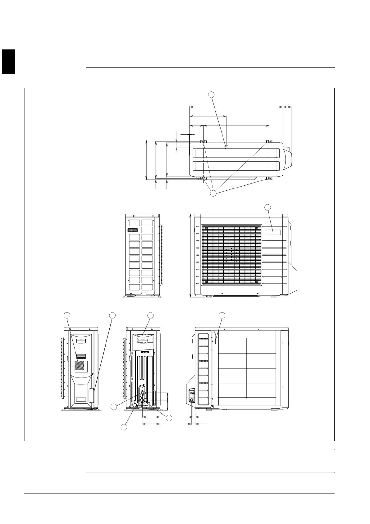
1.2 ERYQ005~007AAV3N: Outlook and Dimensions
Outlook and
dimensions
The illustration below shows the outlook and the dimensions of the unit (mm).
9
825 78
325
124
2
36
300
330
350
25
10
10
580
1
Installation and
service space
In case of removing stop
valve cover
2 3 4 5
8
7
89 64
155 18
160
6
30
See page 1–12.
1–4 Part 1 – System Outline

ESIE06-03 General Outline: Altherma
314
5
Components The table below contains the different components of the unit.
No. Component
1 Brand name label
2 Name plate
3 Wiring inlet
4 Terminal strip with earth terminal
5 Outdoor air temperature thermistor
6 Gas stop valve (φ15.9CuT)
7 Service port
8 Liquid stop valve (φ6.4CuT)
9 Drain outlet (I.D. φ15.9 hose for connection)
10 4-holes for anchor bolts (M8 or M10)
Part 1 – System Outline 1–5
1
General Outline: Altherma ESIE06-03
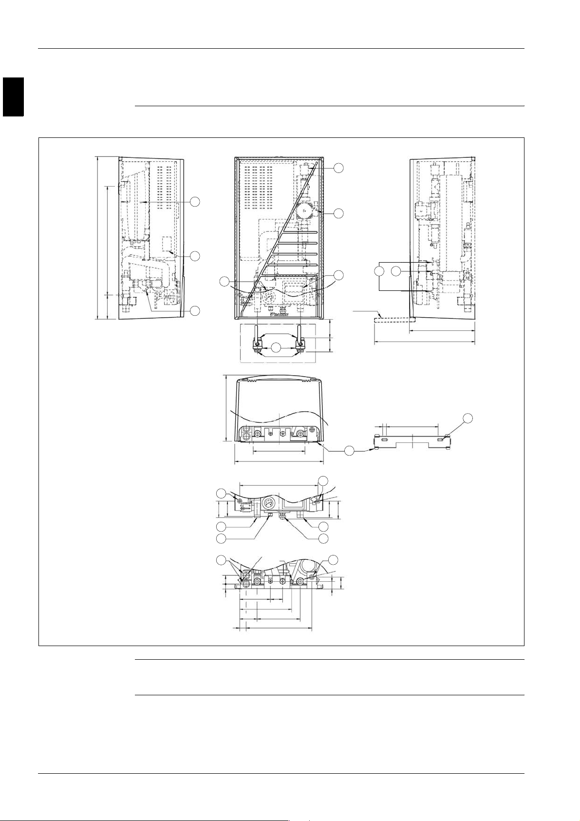
1.3 EKHBH007A***: Outlook and Dimensions
Outlook and
dimensions
The illustration below shows the outlook and the dimensions of the unit (mm).
7
8
1
895
600133
18
9
10
11
1’ Female BSP
14
1’ Male BSP
2
80 ≥100
6
Service door
(CLOSED) 361
(OPEN) 553
Installation and
service space
See page 1–13.
361
20
286
487
431
16
3
13
5
2xØ 30
46
28
170 67
287
23697
36036
16
12
2xØ 12
4
93
Ø 16
19
100
15
65
42
286
16
12
Ø
2x
1–6 Part 1 – System Outline

ESIE06-03 General Outline: Altherma
314
5
Components The table below contains the different components of the unit.
No. Component
1 Pump + switch for speed setting
2 Remocon
3 Water IN connection 1e M BSP
4 Water OUT connection 1e M BSP
5 Power supply intake (+ sanitary warm water tank)
6 Drain/fill valve
7 Air purge
8 Expansion vessel + nipple
9 Blow off valve
10 Pressure gauge
11 Wa terfilte r
12 Suction pipe connection φ15.9 flare connection
13 Liquid pipe connection φ9.52 flare connection
14 Shut off valves (delivered with unit)
15 Thermistor connection (+ sanitary warm water tank)
16 Holes for fixation
17 Blow off drain
18 Switchbox connection terminals
19 Wallbracket
Part 1 – System Outline 1–7
1
General Outline: Altherma ESIE06-03
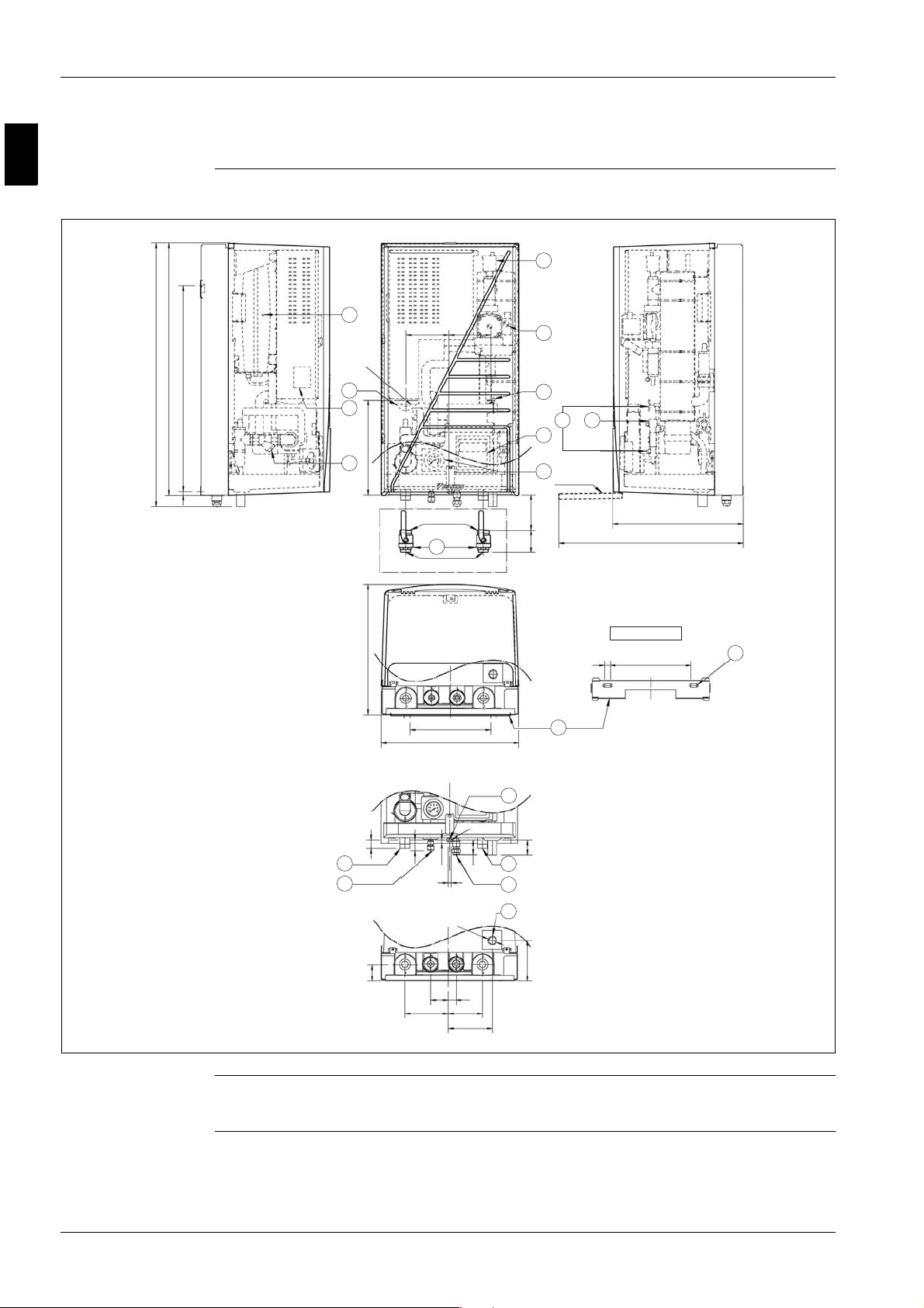
1.4 EKHBX007A***: Outlook and Dimensions
Outlook and
dimensions
The illustration below shows the outlook and the dimensions of the unit (mm).
7
8
895
936
731
Ø 46
5
18
337
11
13
461
152 148
1' Female BSP
14
1' Male BSP
286
487
286
487
1
15
9
6
2
10
Service door
≥125
80
20
(CLOSED) 461
(OPEN) 653
Dimensions wallbracket
286
16
2xØ 12
19
Installation and
service space
See page 1–13.
16
40
62
153 122
Ø 12
12
53
10
Ø
32
28
156
54
4
12
17
144
31
3
13
58
1–8 Part 1 – System Outline

ESIE06-03 General Outline: Altherma
314
5
Components The table below contains the different components of the unit.
No. Component
1 Pump + switch for speed setting
2 Remocon
3 Water IN connection 1e M BSP
4 Water OUT connection 1e M BSP
5 Power supply intake (+ sanitary warm water tank)
6 Drain/fill valve
7 Air purge
8 Expansion vessel + nipple
9 Blow off valve
10 Pressure gauge
11 Wa terfilte r
12 Suction pipe connection φ15.9 flare connection
13 Liquid pipe connection φ9.52 flare connection
14 Shut off valves (delivered with unit)
15 Thermistor connection (+ sanitary warm water tank)
16 Holes for fixation
17 Blow off drain
18 Switchbox connection terminals
19 Wallbracket
Part 1 – System Outline 1–9
1
General Outline: Altherma ESIE06-03
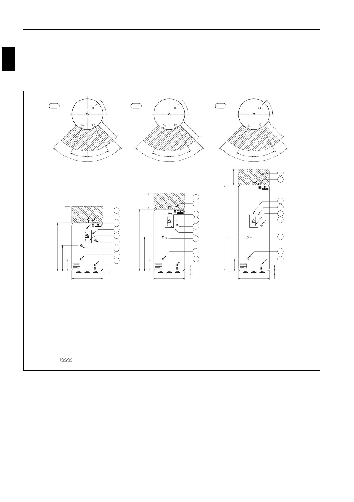
1.5 EKSWW150~300V3: Outlook and Dimensions - Service Space
Outlook and
dimensions Service space
150 L 200 L 300 L
The illustration below shows the outlook and the dimensions of the unit (mm).
47°
400
°
23
30
°
90°
23
°
90°
300
8
300
2
9
6
7
3
900
4
5
475
220
1
1150
630
220
47°
400
30°
23
°
90°
300
8
2
9
6
3
1600
7
4
5
1
630
220
47°
400
30°
8
2
9
6
7
3
4
5
1
580
Required service space
around the tank
0-40 110
580
0-40 110
580
0-40 110
1–10 Part 1 – System Outline

ESIE06-03 General Outline: Altherma
314
5
Components The table below contains the different components of the unit.
No. Component
1 Water mains IN female 3/4’ BSP
2 Water mains OUT female 3/4’ BSP
3 Thermistor connection female 1/2’ BSP
4 Flow (from Hydro-box) female 3/4’ BSP
5 Return (to Hydro-box) female 3/4’ BSP
6 Switchbox
7Clixon
8 Connection female 1/2’ BSP
9 Power entrance
Part 1 – System Outline 1–11
1
General Outline: Altherma ESIE06-03
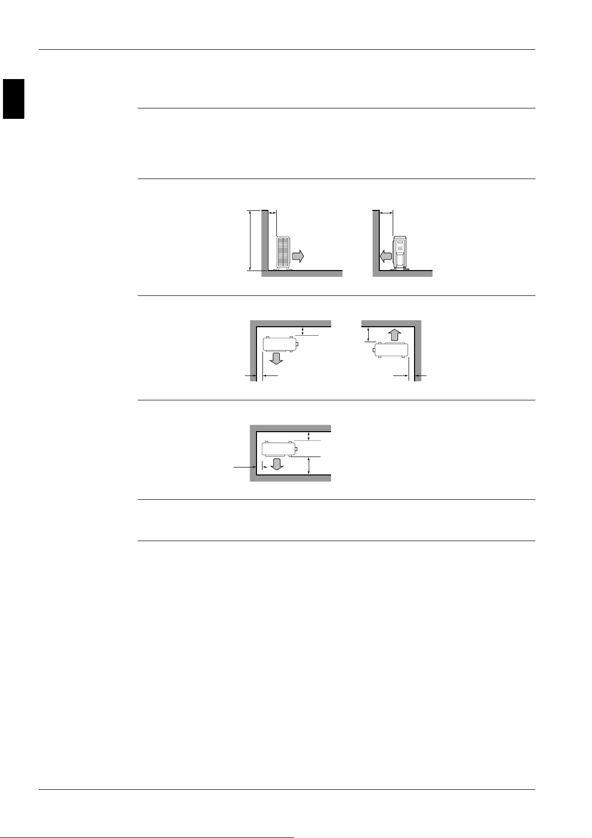
1.6 ERYQ005~007AAV3N: Installation and Service Space
Installing near a
wall or obstacle
Wall facing one side
(unit: mm)
Walls facing two
sides (unit: mm)
P Where a wall or other obstacle is in the path of the outdoor unit air intake or exhaust airflow, follow
the installation guidelines below.
P For any of the installation patterns below, the wall height on the exhaust side should be 1200 mm
or less.
<1200
>100
>100
>50
>350
>350
>50
Walls facing three
sides (unit: mm)
Remark:
P Back to back: 300 mm
P Front to front: 5000 mm
>50
>100
>350
1–12 Part 1 – System Outline
ESIE06-03 General Outline: Altherma
314
5
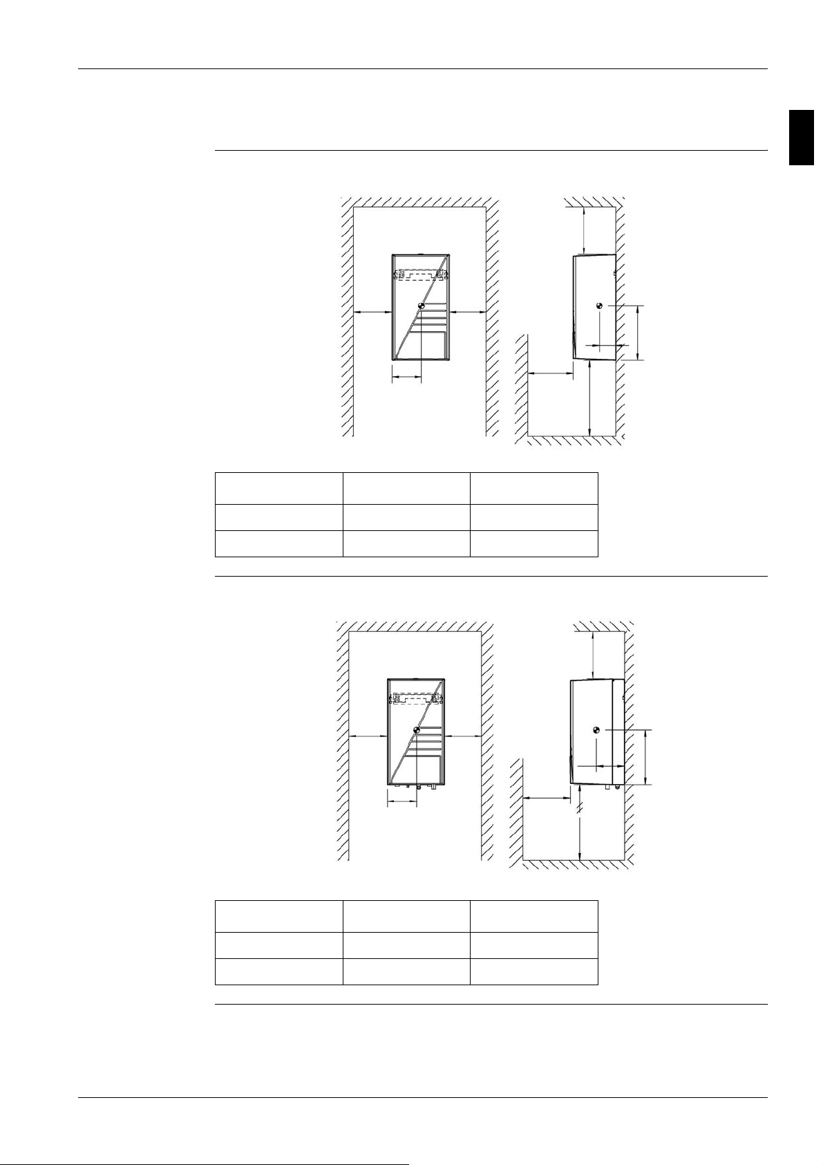
1.7 EKHBH(X)007A: Installation and Service Space
EKHBH The illustration below shows the minimum service space for service and ventilation.
B
A
250
≥ 200
500
≥ 400
172
460
AB
Setup 1 ≥ 200 ≥ 400
Setup 2 ≥ 350 ≥ 200
EKHBX The illustration below shows the minimum service space for service and ventilation.
B
A
250
≥ 200
500
≥ 400
235
460
AB
Setup 1 ≥ 200 ≥ 400
Setup 2 ≥ 350 ≥ 200
Part 1 – System Outline 1–13
1
General Outline: Altherma ESIE06-03
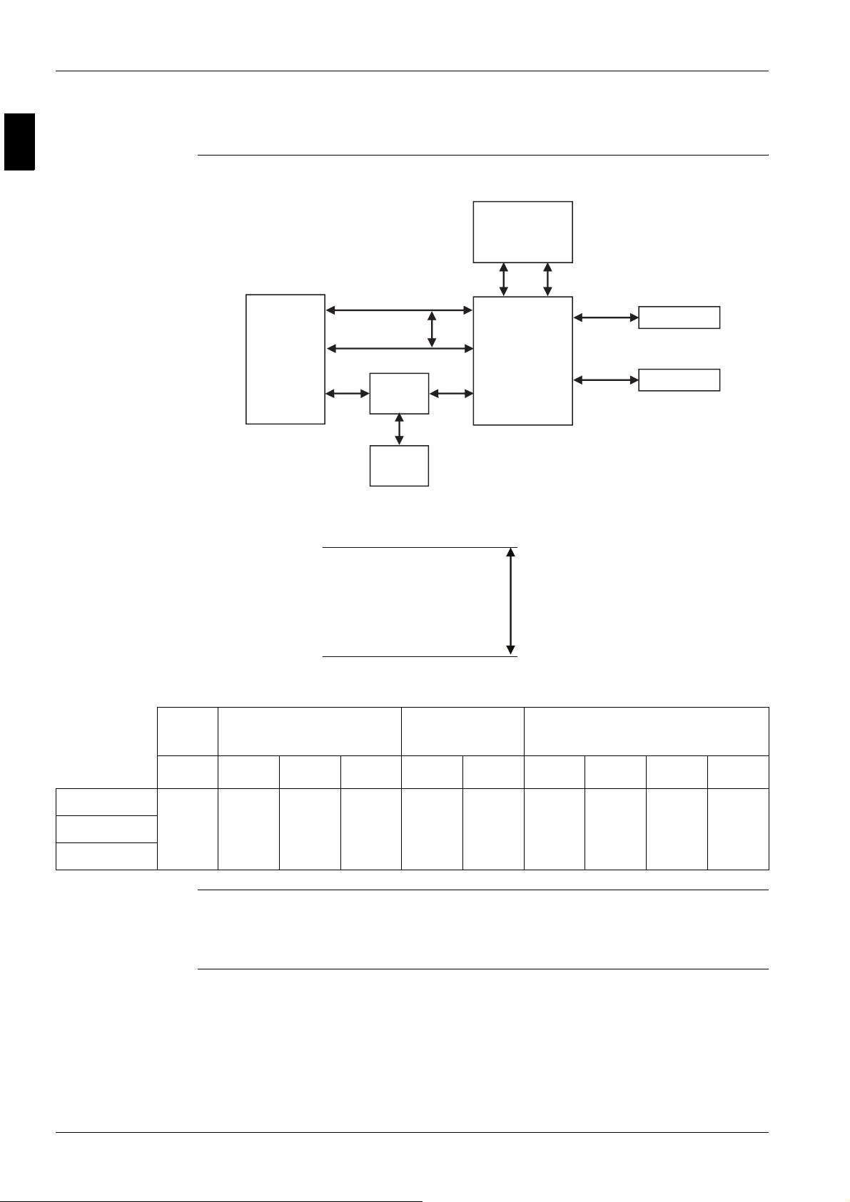
1.8 Physical Limitations and Limits of Operation
Distance between
components
The illustrations and table below show the limitations.
A
G
H
Sanitary
tank
Allowable heigth:
indoor
F
3 way
valve
D
Heat
emitters
BC
OUTDOOR
E
INDOOR
Total system : ≤ 20 m
I
Thermostat
J
2 way valve
outdoor
Piping
R410A
ABCDE FGH I J
ERYQ005ABV3
ERYQ006ABV3
ERYQ007ABV3
Remark E: 123-wiring in/outdoor
3 < A ≤
30m
F: Power supply booster + Q2L safety
G: Thermistor cable supplied with the sanitary tanks is 12 m in length. May not be changed!
Piping water Power supply Communication
≤ 3 m ≤ 10 m
depend
on instal-
lation
depend
on instal-
lation
depend
on instal-
lation
(outdoor unit can be above
or below the hydro-box)
depend
12 m > 0.05 m
on instal-
lation
depend
on instal-
lation
1–14 Part 1 – System Outline

ESIE06-03 Specifications
314
5
Part 1
2 Specifications
2.1 What Is in This Chapter?
Introduction This chapter contains the following information:
P Technical specifications
P Electrical specifications
Altherma This chapter contains the following specifications:
Specifications See page
2.2–ERYQ005~007 1–16
2.3–EKHBH and EKHBX 1–18
2.4–EKSWW150~300V3/Z2 1–20
Part 1 – System Outline 1–15
1
Specifications ESIE06-03
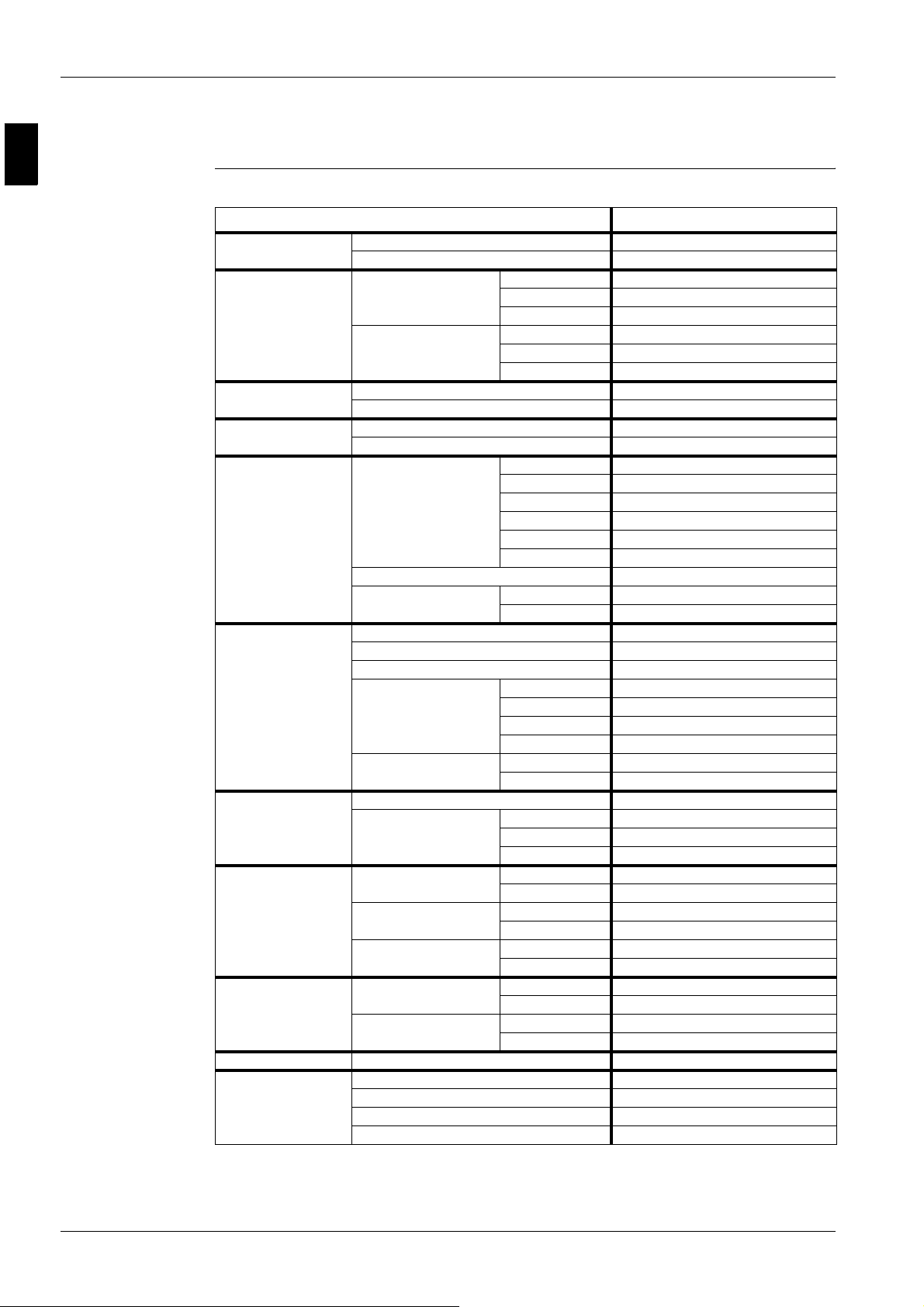
2.2 ERYQ005~007
Technical
specifications
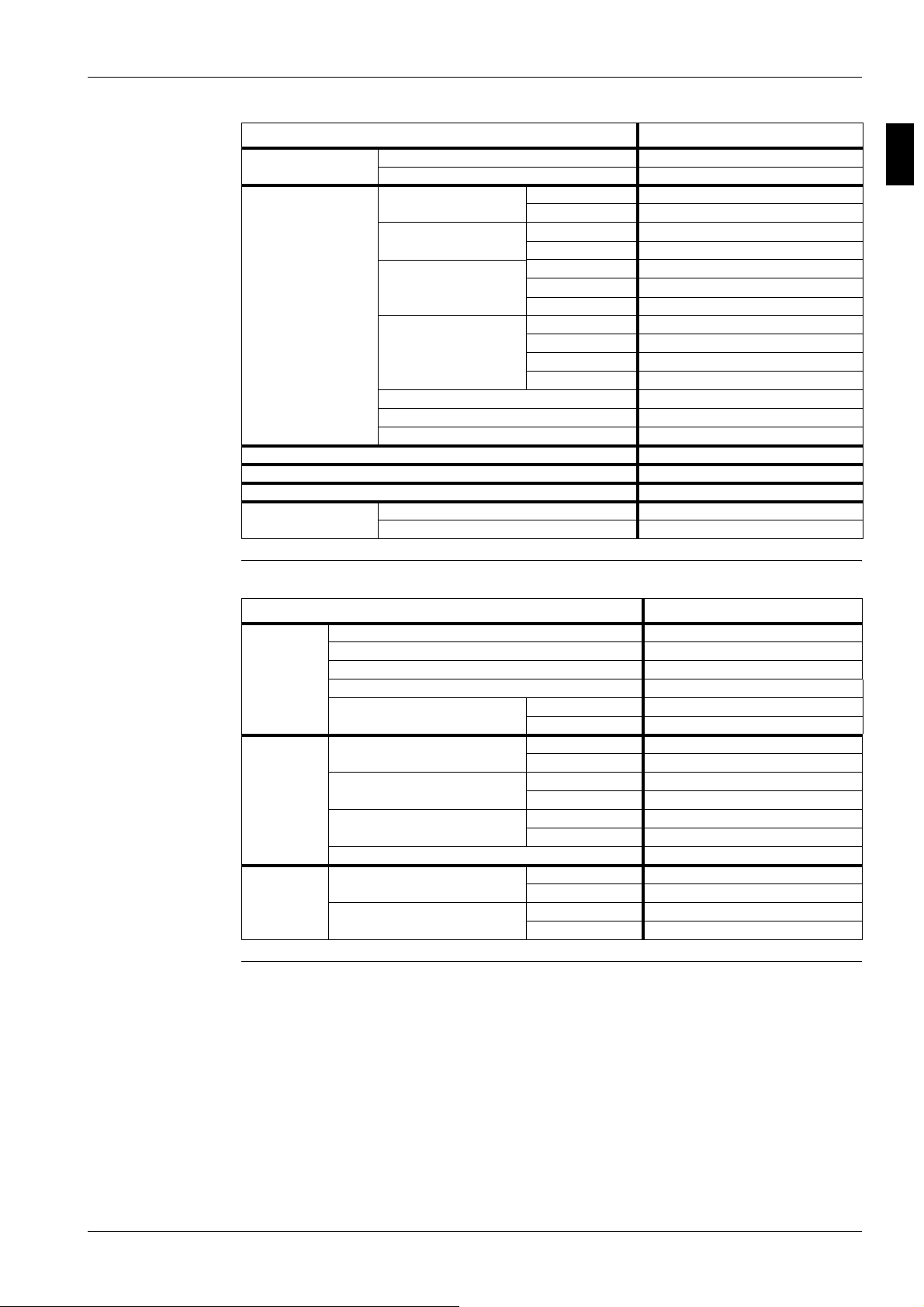
The table below contains the technical specifications.
Specification ERYQ005~007
Casing
Dimensions
Weight
Packing Material EPS, CARTON
Heat exchanger Specifications Length 845 mm
Fan Type Propeller
Compressor Quantity 1
Operation range (see Altherma
operation manual)
Sound level (nominal) Heating Sound power (5/6/7) 64/64/66 dBA
Sound level (night quiet) Sound pressure —
Refrigerant Type R410A
Colour Ivory white
Material Polyester painted galvanised steel
Packing Height 797 mm
Width 960 mm
Depth 390 mm
Unit Height 735 mm
Width 825 mm
Depth 300 mm
Machine weight 56 kg
Gross weight 61 kg
Weight 5 kg
Nr. of rows 2
Fin pitch 1.8 mm
Nr. of passes —
Face area —
Nr. of stages 32 m²
Tube type Hi-Xa(8)
Fin Type WF fin
Treatment Anti-corrosion treatment (PE)
Discharge direction Horizontal
Quantity 1
Air flow rate (nominal at 230 V) Heating high —
Heating low —
Cooling high —
Cooling low —
Motor Quantity 1
Output 53 W
Motor Model 2YC63BXD#C
Type Hermetically sealed swing compressor
Output 1920 W
Heating Min. -20°C DB
Max. 25°C DB
Cooling Min. 7°C WB
Max. 20°C WB
Sanitary water Min. -20°C DB
Max. 43°C DB
Sound pressure (5/6/7) 48/48/52 dBA
Cooling Sound power 63/64/66 dBA
Sound pressure (5/6/7) 47/47/53 dBA
Charge 1.7 kg
Control Expansion valve (electronic type)
Nr. of circui ts 1
1–16 Part 1 – System Outline
ESIE06-03 Specifications
314
5
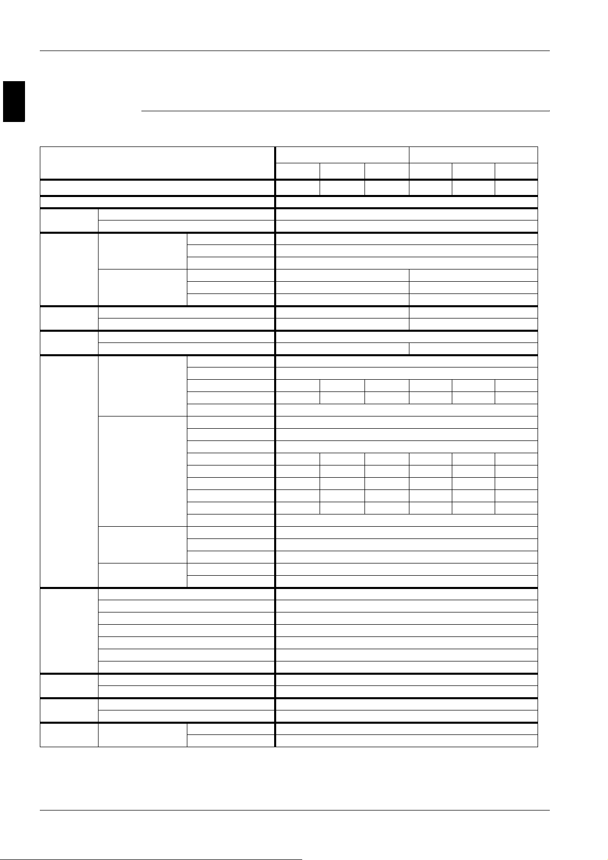
Specification ERYQ005~007
Refrigerant oil Type FVC50K
Charged volume 0.75 l
Piping connections Liquid Type Flare connection
Diameter (OD) 6.35 mm
Gas
Drain Quantity 1
Piping length Min. 3 m
Additional refrigerant charge 0.02 IF > 10 m
Installation height difference max. 15 m
Max. interunit level difference 20 m
Defrost method Reverse cycle
Defrost control Sensor for outdoor heat exchanger temperature
Capacity control method Inverter controlled
Standard accessories Item Installation manual, drain plug
Quanti ty 1
Type Flare connection
Diameter (OD) 15.9 mm
Type Socket
Diameter (OD) 18 mm
Max. 30 m
Equivalent —
Chargeless —
Electrical
specifications
The table below contains the electrical specifications.
Specification ERYQ00
Power supply Name V1
Phase 1
Frequency 50 Hz
Volt age 220 V-240 V
Voltage range Minimum -10% (V)
Maximum +10% (V)
Current Nominal running current Cooling —
Heating —
Starting current Cooling 11 A
Heating 11 A
Maximum running current Cooling 16.25 A
Heating 18 A
Recommended fuses 20 A
Wire connections For power supply Quantity 3
Remark —
For connection with hydro-box Quantity 4
Remark Included earth wiring
Part 1 – System Outline 1–17
1
Specifications ESIE06-03
2.3 EKHBH and EKHBX
Technical
The table below contains the technical specifications.
specifications
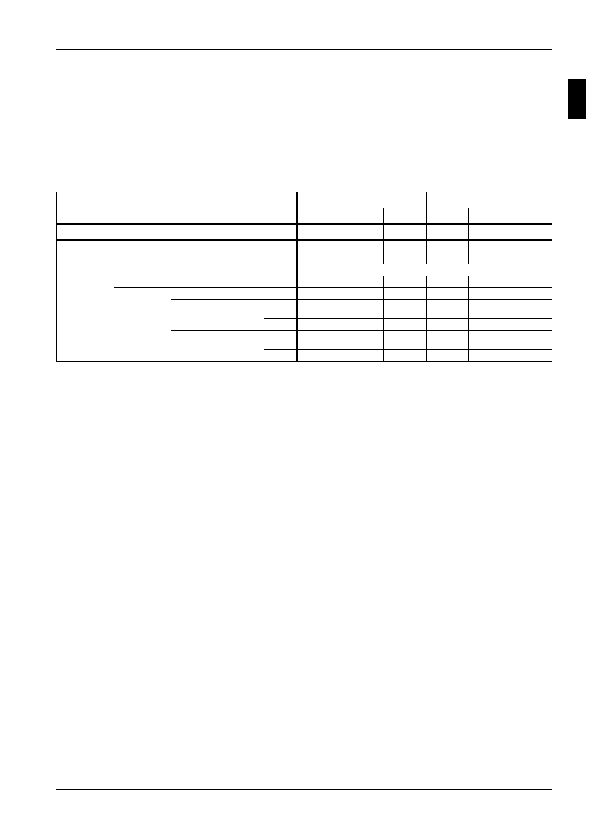
Specification EKHBH* EKHBX*
EKHBH007A* EKHBH007A* EKHBH007A* EKHBX007* EKHBX007* EKHBX007*
Outdoor units ERYQ005A ERYQ006A ERYQ007A ERYQ005A ERYQ006A ERYQ007A
Nominal input (indoor only without electric heater) 230 W
Casing Colour RAL9010
Material E poxy polyester painted galvanised steel
Dimensions Packing Height 1225 mm
Width 660 mm
Depth 595 mm
Unit Height 895 mm 936 mm
Width 487 mm 487 mm
Depth 361 mm 461 mm
Weight Machine weigth 55 kg 65 kg
Gross weight 65 kg 75 kg
Packing Material EPS/Wood/Carton/PS (straps)
Weight 10 kg 10 kg
Main components Pump Type Water cooled
Nr. of speed 3
Nominal ESP unit Cooling — — — 49.9 kPa 46.5 kPa 44.4 kPa
Nominal ESP unit Heating 46.5 kPa 40.1 kPa 29.0 kPa 46.5 kPa 40.1 kPa 29.0 kPa
Power input 130 W
Water side Heat exchanger Type Brazed plate
Quantity 1
Water volume 0.67 l
Water flow rate Min. 12 l/min 12 l/min 12 l/min 12 l/min 12 l/min 12 l/min
Water flow rate Nom. Cooling — — — 14.7 l/min 16.5 l/min 17.6 l/min
Water flow rate Nom. Heating 16.5 l/min 19.6 l/min 24.2 l/min 16.5 l/min 19.6 l/min 24.2 l/min
Water flow rate Max. Cooling — — — — — —
Water flow rate Max. Heating — — — — — —
Insulation material Polyurethane foam
Expansion vessel Volume 10 l
Max. water pressure 3 bar
Pre-pressure 1 bar
Water filter Diameter perforations 1 mm
Material Brass
Water circuit Piping connections diameter 1” MBSP
Piping 1” MBSP
Safety valve 3
Manometer Yes
Drain valve/Fill valve Yes
Shut off valve Yes
Air purge valve Yes
Refrigerant ciruit Gas side diameter 15.9 mm
Liquid side diameter (2)
Sound level Sound pressure 27 dBA
Sound power —
Operation range Waterside Cooling 7~20°C
Heating 30~55°C
1–18 Part 1 – System Outline
ESIE06-03 Specifications
314
5
Notes: 1 The sound pressure level is measured via a microphone at a certain distance from the unit. It is a relative value, depending on
the distance and acoustic environment:
2 (2):
P ERYQ-models: 6.35 mm
P EKHB-models: 9.52 mm (flare connection)
Electrical
The table below contains the electrical specifications.
specifications
Specification EKHBH* EKHBX*
EKHBH007A* EKHBH007A* EKHBH007A* EKHBX007* EKHBX007* EKHBX007*
Outdoor units ERYQ005A ERYQ006A ERYQ007A ERYQ005A ERYQ006A ERYQ007A
Electric heater Type 3V3 6V3 6W1 6T1 9W1 9T1
Power supply Phase 1~ 1~ 3N~ 3~ 3N~ 3~
Frequency 50 Hz
Voltage 230 V 230 V 400 V 230 V 400 V 230 V
Current Running current 13 A 26 A 8.6 A 15 A 13 A 23 A
Zmax. List No
Text — 0.25 + j0.15 — — — —
Zmax. electric heater + booster
heater (EKSWW* models)
List — — No
Text 0.25 + j0.15 0.17 + j0.10 — — — —
requirements
—No
requirements
requirements
Out of scoop No
Out of scoop No
requirements
requirements
Out of scoop
Out of scoop
Notes: 1
Electric heater has 2 capacity steps except for the 3V3 model which has only 1 capacity step.
Part 1 – System Outline 1–19
1
Specifications ESIE06-03
2.4 EKSWW150~300V3/Z2
Technical
The table below contains the technical specifications.
specifications
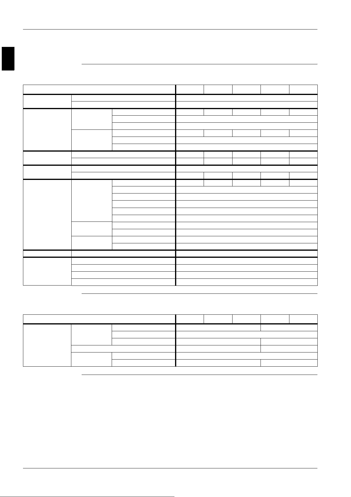
Specification EKSWW150V3 EKSWW200V3 EKSWW300V3 EKSWW200Z2 EKSWW300Z2
Casing Colour Neutral white
Material Epoxy-coated mild steel
Dimensions Packing Height 950 mm 1200 mm 1650 mm 1200 mm 1650 mm
Width 600 mm
Depth 600 mm
Unit Height 900 mm 1150 mm 1600 mm 1150 mm 1600 mm
Width 580 mm
Depth 580 mm
Weight Machine weigth 37 kg 45 kg 59 kg 45 kg 59 kg
Gross weight 40 kg 49 kg 64 kg 49 kg 64 kg
Packing Material EPS/Carton
Weight 3 kg 4 kg 5 kg 4 kg 5 kg
Main components Tank Water volume 150 l 200 l 300 l 200 l 300 l
Material Stainless steel (DIN 1.4521)
Max. temperature 85°C
Max. water pressure 10 bar
Insulation Material Polyurethane foam
Insulation Min. thickness 40 mm
Heat exchanger Quantity 1
Material Stainless steel (DIN 1.4401)
Booster heater Quantity 1
Capacity 3 kW
Temperature sensor Cable length 12 m
Piping connections Water inlet H/E Diameter 3/4” FBSP (inch)
Water outlet H/E Diameter 3/4” FBSP (inch)
Cold water in Diameter 3/4” FBSP (inch)
Hot water out Diameter 3/4” FBSP (inch)
Electrical
The table below contains the electrical specifications.
specifications
Specification EKSWW150V3 EKSWW200V3 EKSWW300V3 EKSWW200Z2 EKSWW300Z2
Unit Power supply Phase 1~ 2~
Frequency 50 Hz
Voltage 230 V 400 V
Nominal running current 13 A 7.5 A
Fuse Size 20 A
Phase 1~ 2~
1–20 Part 1 – System Outline
ESIE06-03 Functional Diagrams
314
5
Part 1
3 Functional Diagrams
3.1 What Is in This Chapter?
Introduction This chapter contains the following information:
P Overview complete system
P Electrical connection diagram
P Pipe connection diameters.
Functional
diagrams
This chapter contains the following functional diagrams:
Functional diagram See page
3.2–Complete System 1–22
3.3–Electrical Connection Diagram 1–24
3.4–Pipe Connection Diameters 1–25
Part 1 – System Outline 1–21
1
Functional Diagrams ESIE06-03
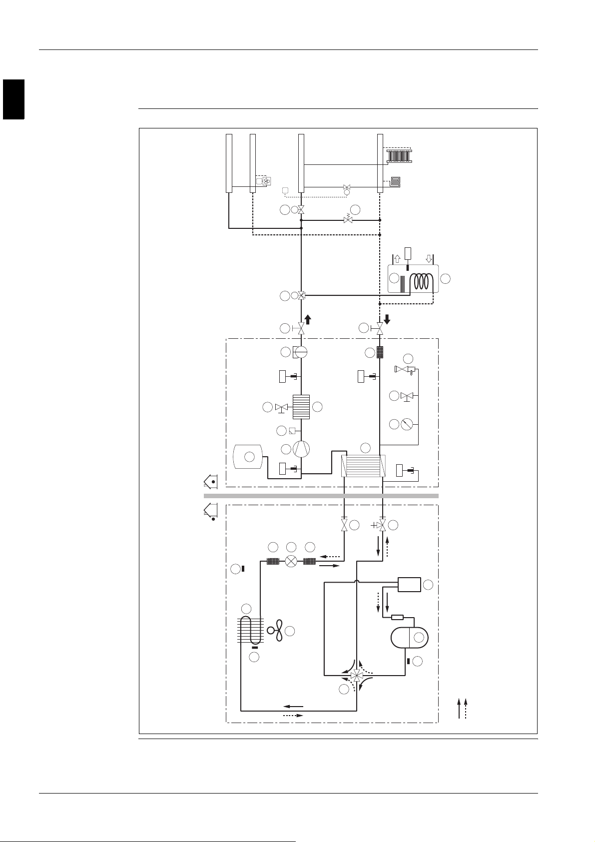
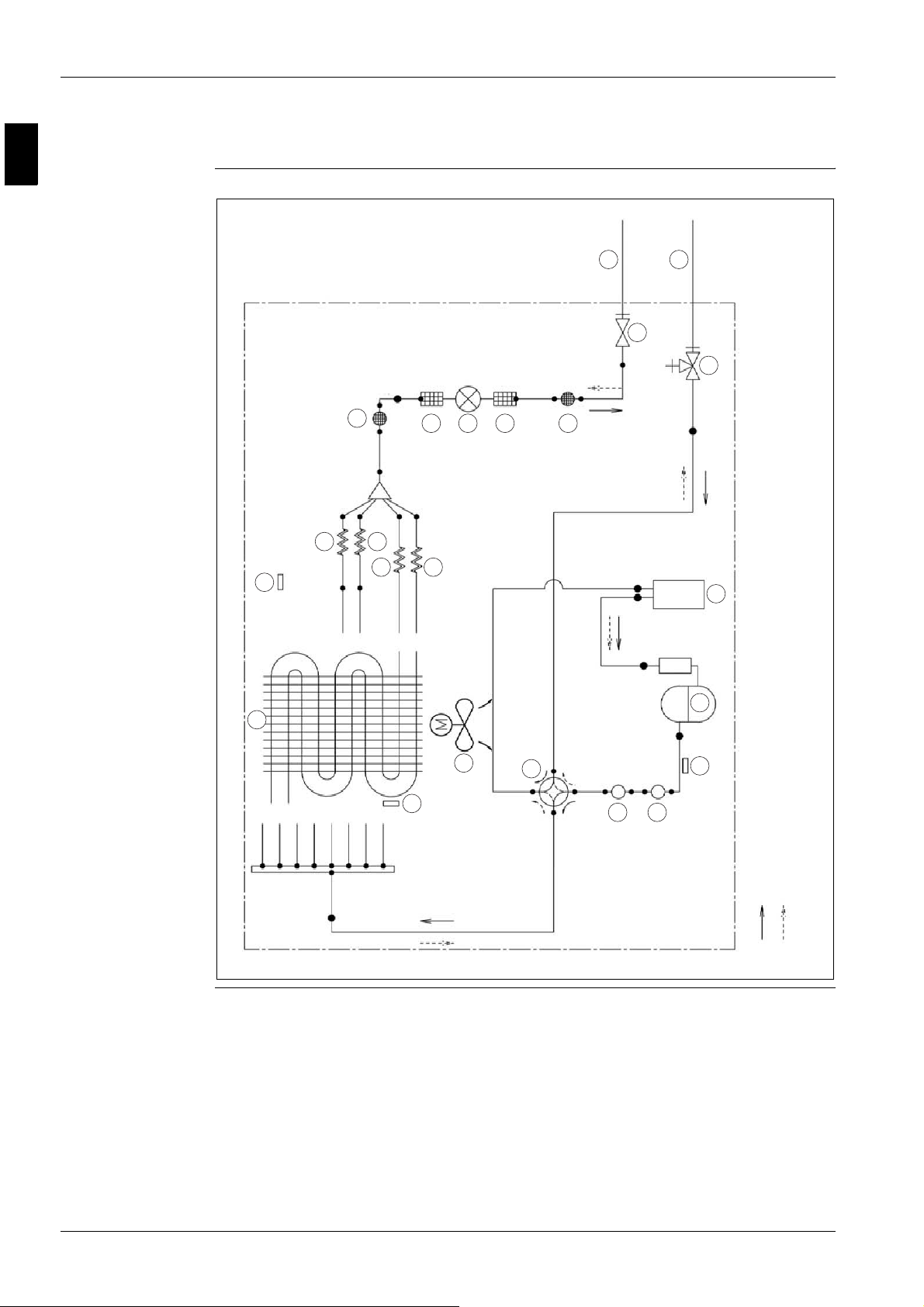
3.2 Complete System
T1
FCU1
T1
M1
M
M
19 24 27
17
t >
R2T
16
15
R1T
14
t >
13
18
28
t >
R5T
25
20
5
t >
R4T
O
2
2
H
2221
R3T
23
t >
26
7
5
6
5
1
2
M
4
3
12
8
9
10
11
cooling
heating
refrigerant flow
1–22 Part 1 – System Outline

ESIE06-03 Functional Diagrams
314
5
Components The table below contains the different components of the functional diagrams.
No. Name
1 Outdoor air temperature thermistor
2 Heat exchanger
3 Heat exchanger thermistor
4 Propeller fan
5Filter
6 Expansion valve
7 Liquid stop valve
8
Gas stop valve with service port
9 Accumulator
10 Compressor
11 Discharge pipe thermistor
12 4-way valve ON: heating
13 Expansion vessel
14 Pump
15 Air purge valve
16 Drain valve
17
Flow switch
18 Backup heater
19 Outlet
20 Inlet
21 Manometer
22 Fill and drain valve
23 Pressure relief valve
24 3-way valve for sanitary water tank
25 Booster heater
26 SWW tank
27 2-way valve for cooling mode
28 By-pass valve
R1T Outlet water Heatexchanger thermistor
R2T Outlet water Backup heater thermistor
R3T Refrigerant water thermistor
R4T Inlet water thermistor
R5T Sanitary water tank thermistor
Part 1 – System Outline 1–23

1
Functional Diagrams ESIE06-03
3.3 Electrical Connection Diagram
Standard parts
Power Supply
unit power supply: 230V + earth
backup heater power supply (3/6/9kW): 400V or 230V + earth
Optional power supply:
booster heater power supply(3kW): 400V or 230V + earth
3 core
3 core
Optional parts
SANITARY
TANK
Power supply
booster heater
Q2L - Clixon
booster heater
R5T - Thermistor
water temperature
5 core
5Gx2.5
230V or 400V
2 core
signal
Thermistor cable
NOTE: min. distance
to power cable = 3cm
3 or 4 core
OUTDOOR UNIT
X1M:L-N-earth
X2M:1-2-3-earth
<10m:4Gx1.5
<10m:4Gx2.5
F1B
F2B
X1M:7-8-earth X1M:13-15-17-23
X1M:21-22
X9A (PCB A1P)
4 core
X1M:9-10-11-earth
NO valve: X1M:16-18
NO valve: X1M:14-18
X1M:19-20
HYDRO-BOX
user
interface
For more details
please check unit wiring diagram
Field supply
4 core
230V
2 core
230V
Room thermostat
A3P (optional)
2way valve
M2S (EKHBX units)
for cooling mode
3way valve
M3S (when EKSWW is installed)
1–24 Part 1 – System Outline
ESIE06-03 Functional Diagrams
314
5
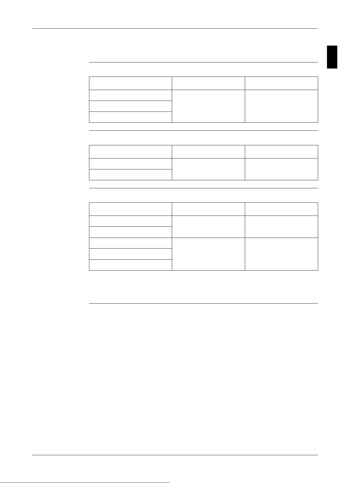
3.4 Pipe Connection Diameters
Outdoor units The table below contains the refrigerant pipe connection diameters.
Model ∅ Gas pipe (flare) ∅ Liquid pipe (flare)
ERYQ005ABV3 15.9 mm 6.4 mm
ERYQ006ABV3
ERYQ007ABV3
Hydro-box The table below contains the refrigerant pipe connection diameters.
Model ∅ Gas pipe (flare) ∅ Liquid pipe (flare)
EKHBH007A 15.9 mm 6.4 mm
EKHBX007A
Hydro-box + water
side
The table below contains the water inlet/outlet connection diameters.
Model ∅ Gas pipe (flare) ∅ Liquid pipe (flare)
EKHBH007A 1 inch
EKHBX007A
EKSWW150 3/4 inch
EKSWW200
EKSWW300
1: MBSP = male British standard pipe
2: FBSP = female British standard pipe
(MBSP)
(FBSP)
1
2
1 inch
(MBSP)
3/4 inch
(FBSP)
Part 1 – System Outline 1–25

1
Functional Diagrams ESIE06-03
1–26 Part 1 – System Outline
ESIE06-03 Piping Diagrams
314
5
Part 1
4Piping Diagrams
4.1 What Is in This Chapter?
Introduction This chapter contains the following information:
P Piping diagrams
Piping diagrams This chapter contains the following piping diagrams:
Functional diagram See page
4.2–ERYQ005~007 1–28
4.3–EKHBH(X) 1–30
Part 1 – System Outline 1–27
1
Piping Diagrams ESIE06-03
4.2 ERYQ005~007
11
(6.4 CuT)
11
(15.9 CuT)
10
12
6.4 CuT
6.4 CuT
4
5
6.4 CuT
8
9
6
7
3
19
7.9 CuT 4.0 CuT
7.9 CuT 4.0 CuT
4.0 CuT
4.0 CuT
12.7 CuT
6.4 CuT
8
7
6.4 CuT
12.7 CuT
13
12.7 CuT
1
7.9 CuT
7.9 CuT
7.9 CuT
7.9 CuT
7.9 CuT12.7 CuT
7.9 CuT
7.9 CuT
18
2
7.9 CuT
17
7.9 CuT
7.9 CuT
16
12.7 CuT 12.7 CuT
Outdoor Unit
15 14
16
cooling
heating
refrigerant flow
1–28 Part 1 – System Outline

ESIE06-03 Piping Diagrams
314
5
Components The table below contains the different components of the functional diagrams.
No. Name
1 Heat exchanger
2 Heat exchanger thermistor
3 Capillary Tube 1
4 Capillary Tube 2
5 Capillary Tube 3
6 Capillary Tube 4
7 Muffler with filter
8Filter
9 Motor operated valve
10 Liquid stop valve
11 Field piping
12 Gas stop valve with service port
13 Accumulator
14 Compressor
15 Discharge pipe thermistor
16 Muffler
17 4-way valve on: heating
18 Propeller fan
19 Outdoor air temperature thermistor
Part 1 – System Outline 1–29

1
Piping Diagrams ESIE06-03
4.3 EKHBH(X)
WATER SIDE
R4T
FIELD INSTALLATION
t >
INLET
2
OUTLET
2
FIELD INSTALLATION
5
1
43
OPTION
BACKUP HEATER
4
10
R2T
t >
9
8
7
R1T
t >
6
REFRIGERANT SIDE
WATER INLET
EVAPORATOR
CONDENSOR
t >
R3T
: COOLING (EKHBX)
: HEATING (EKHBX + EKHBH)
REFR. OUT
OVERVIEW
WATER
REFR.
REFR. IN
WATER OUTLET
SIDE
SIDE
REFR. IN
OUTDOOR UNIT
REFR. OUT
1–30 Part 1 – System Outline
 Loading...